Greenlee Textron 1990 Crimping ToolGreenlee Textron / Subsidiary of Textron Inc. 4 1990 Dieless...
26
999 8517.9 © 2000 Greenlee Textron SB 226 REV 5 4/00 SERVICE MANUAL Read and understand all of the instructions and safety information in this manual before operating or servicing this tool. 1990 Dieless Hydraulic Crimping Tool Serial Codes WH and YM
Transcript of Greenlee Textron 1990 Crimping ToolGreenlee Textron / Subsidiary of Textron Inc. 4 1990 Dieless...
999 8517.9 © 2000 Greenlee Textron SB 226 REV 5 4/00
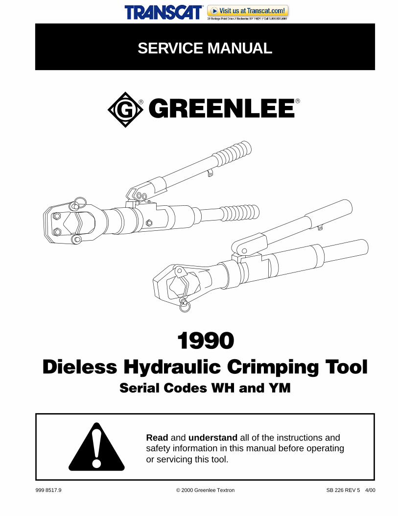
SERVICE MANUAL
Read and understand all of the instructions andsafety information in this manual before operatingor servicing this tool.
1990Dieless Hydraulic Crimping Tool
Serial Codes WH and YM
Greenlee Textron / Subsidiary of Textron Inc. 2 4455 Boeing Dr., Rockford, IL 61109-2988 815/397-7070
1990 Dieless Hydraulic Crimping Tool
KEEP THIS MANUAL
Table of Contents
Description ................................................................... 2
Safety ........................................................................... 2
Purpose ........................................................................ 2
Other Publications ........................................................ 2
Important Safety Information ........................................ 3
Identification ................................................................. 4
Tools and Supplies ....................................................... 5
Pressure Check Procedure .......................................... 5
Pressure Adjustment Procedure .................................. 6
Pressure Calibration Check ......................................... 7
Air Purging and Oil Filling Procedure ........................... 8
Die Replacement .......................................................... 9
Disassembly ......................................................... 10–11
Assembly .............................................................. 12–15
Service Tips ............................................................... 15
Retrofit Kits ................................................................. 16
Troubleshooting ......................................................... 17
Illustrations and Parts Lists .................................. 18–25
Description
The Greenlee 1990 Dieless Hydraulic Crimping Tool is aself-contained tool intended to crimp copper andaluminum compression connectors. A single set ofintegral dies provides a wide crimping range.
The Greenlee 1990 is protected by U.S. Patent No.4,796,461.
Safety
Safety is essential in the use and maintenance ofGreenlee tools and equipment. This manual and anymarkings on the tool provide information for avoidinghazards and unsafe practices related to the use andmaintenance of this tool. Observe all of the safetyinformation provided.
Purpose
This manual is intended to familiarize authorizedGreenlee service center personnel with the safeoperation and maintenance procedures for the followingGreenlee tools:
• 1990 Serial Code WH
• 1990 Serial Code YM
Keep this manual available to all personnel.
Replacement manuals are available upon request at nocharge.
Greenlee and are registered trademarks of
Greenlee Textron.
Dow Corning, Silastic and 732 are registered trade-marks of Dow Corning Corporation.
Loctite is a registered trademark of Loctite Corporation.
Univis is a registered trademark of Exxon Corporation.
Other Publications
Instruction Manuals:
• Serial Code WH: Publication 999 8425.3 (IM-1006)
• Serial Code YM: Publication 999 9994.3 (IM-1093)
Greenlee Textron / Subsidiary of Textron Inc. 3
1990 Dieless Hydraulic Crimping Tool
IMPORTANT SAFETY INFORMATION
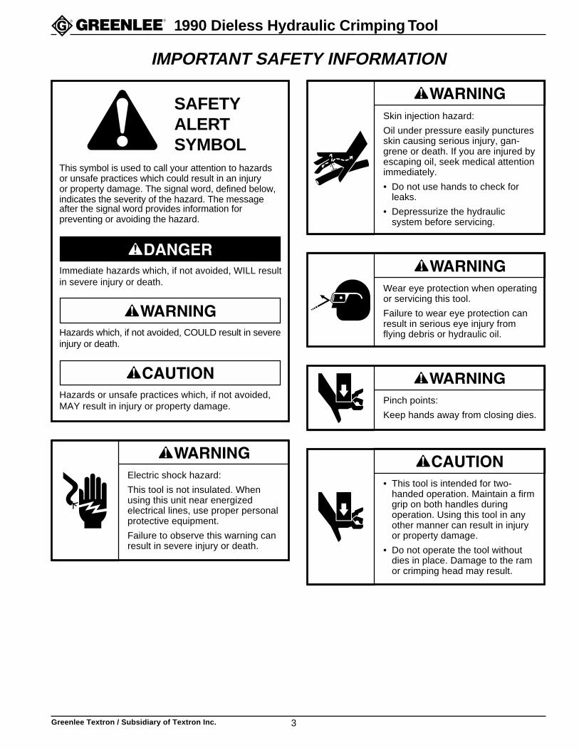
Electric shock hazard:
This tool is not insulated. Whenusing this unit near energizedelectrical lines, use proper personalprotective equipment.
Failure to observe this warning canresult in severe injury or death.
Skin injection hazard:
Oil under pressure easily puncturesskin causing serious injury, gan-grene or death. If you are injured byescaping oil, seek medical attentionimmediately.
• Do not use hands to check forleaks.
• Depressurize the hydraulicsystem before servicing.
Wear eye protection when operatingor servicing this tool.
Failure to wear eye protection canresult in serious eye injury fromflying debris or hydraulic oil.
Pinch points:
Keep hands away from closing dies.
• This tool is intended for two-handed operation. Maintain a firmgrip on both handles duringoperation. Using this tool in anyother manner can result in injuryor property damage.
• Do not operate the tool withoutdies in place. Damage to the ramor crimping head may result.
This symbol is used to call your attention to hazardsor unsafe practices which could result in an injuryor property damage. The signal word, defined below,indicates the severity of the hazard. The messageafter the signal word provides information forpreventing or avoiding the hazard.
Hazards or unsafe practices which, if not avoided,MAY result in injury or property damage.
Hazards which, if not avoided, COULD result in severeinjury or death.
Immediate hazards which, if not avoided, WILL resultin severe injury or death.
SAFETYALERTSYMBOL
Greenlee Textron / Subsidiary of Textron Inc. 4
1990 Dieless Hydraulic Crimping Tool
Identification
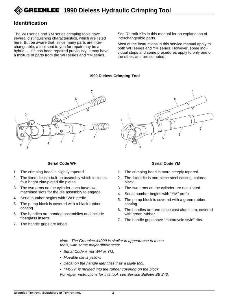
Serial Code WH
1. The crimping head is slightly tapered.
2. The fixed die is a bolt-on assembly which includesfour bright zinc-plated die plates.
3. The two arms on the cylinder each have twomachined slots for the die assembly to engage.
4. Serial number begins with “WH” prefix.
5. The pump block is covered with a black rubbercoating.
6. The handles are bonded assemblies and includefiberglass inserts.
7. The handle grips are lobed.
Note: The Greenlee 44999 is similar in appearance to thesetools, with some major differences:
• Serial Code is not WH or YM.
• Movable die is yellow.
• Decal on the handle identifies it as a utility tool.
• “44999” is molded into the rubber covering on the block.For repair instructions for this tool, see Service Bulletin SB 243.
Serial Code YM
1. The crimping head is more steeply tapered.
2. The fixed die is one-piece steel casting, coloredblack.
3. The two arms on the cylinder are not slotted.
4. Serial number begins with “YM” prefix.
5. The pump block is covered with a green rubbercoating.
6. The handles are one-piece cast aluminum, coveredwith green rubber.
7. The handle grips have “motorcycle style” ribs.
The WH series and YM series crimping tools haveseveral distinguishing characteristics, which are listedhere. But be aware that, since many parts are inter-changeable, a tool sent to you for repair may be ahybrid — if it has been repaired previously, it may havea mixture of parts from the WH series and YM series.
See Retrofit Kits in this manual for an explanation ofinterchangeable parts.
Most of the instructions in this service manual apply toboth WH series and YM series. However, some indi-vidual steps and some procedures apply to only one orthe other, and are so noted.
1990 Dieless Crimping Tool
13
6
7
32 4 5
76
13
6
7
3
45
7
6
2
Greenlee Textron / Subsidiary of Textron Inc. 5
1990 Dieless Hydraulic Crimping Tool
Tools and Supplies
Before beginning any repair procedure in this manual,read the entire section to be sure all of the necessarytools and supplies are available.
Tools and supplies for most procedures include:
• Bench vise with jaw protectors to secure the tool
• Quality pressure gauge with 1/2% accuracy and arange of 0 to 700 Bar (0 to 10,000 psi)
• Gauge adapter:
Serial Code WH: 1/16" NPT male pipe adapter
Serial Code YM: 1/8" SAE straight thread adapter(Greenlee 36246)
• 32 mm (1-1/4") diameter aluminum rod, at least76 mm (3") long
• RTV (room-temperature vulcanizing) silicone rubberadhesive/sealant, such as Dow Corning® Silastic®
732® Multipurpose Sealant
• Pressure Test Kit (Greenlee 32891)
• Exxon Univis® J26 hydraulic oil
• Serial Code WH only: dry white lubricant(silicone or talcum)
Tools and supplies for some specific proceduresinclude:
• C-clamp, arbor press, or other means of retaining theram spring when disassembling and assembling thecylinder
• Spanner wrench for removing the pressure-adjustingvalve body from the pump block
Pressure Check Procedure
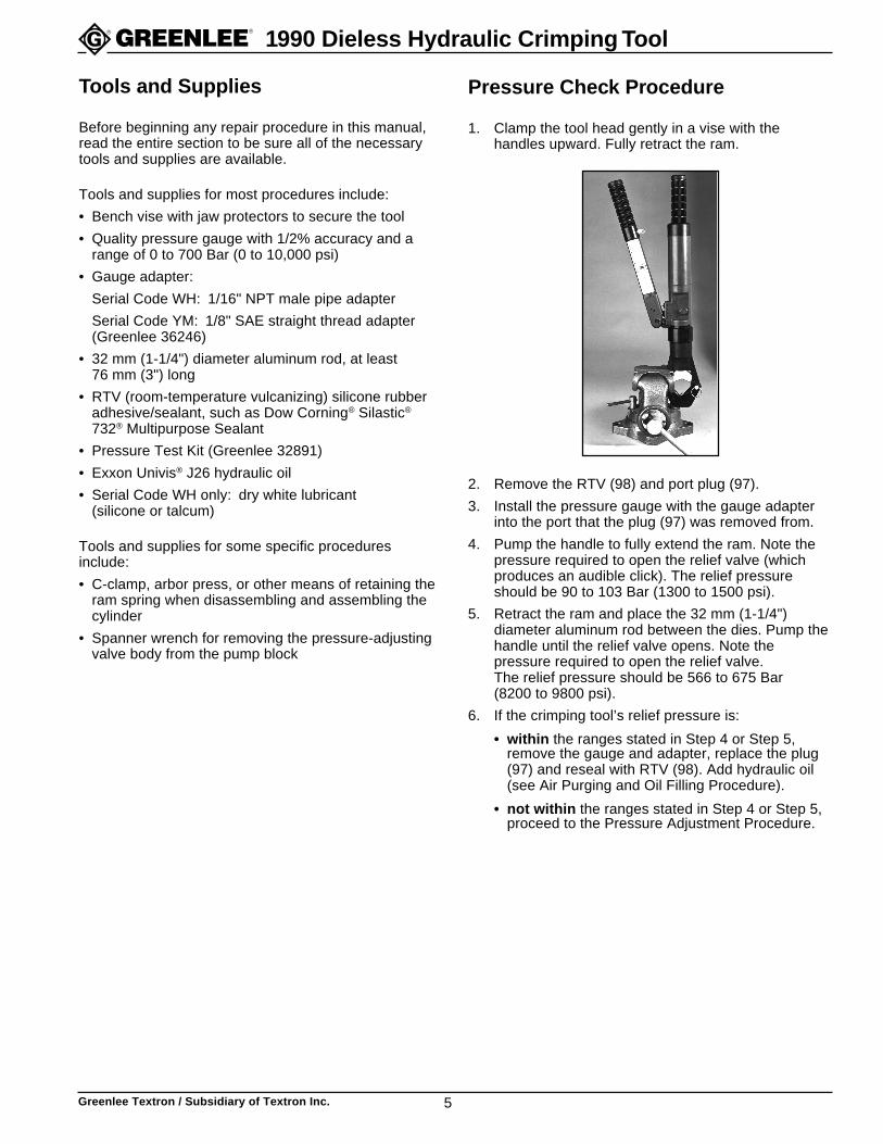
1. Clamp the tool head gently in a vise with thehandles upward. Fully retract the ram.
2. Remove the RTV (98) and port plug (97).
3. Install the pressure gauge with the gauge adapterinto the port that the plug (97) was removed from.
4. Pump the handle to fully extend the ram. Note thepressure required to open the relief valve (whichproduces an audible click). The relief pressureshould be 90 to 103 Bar (1300 to 1500 psi).
5. Retract the ram and place the 32 mm (1-1/4")diameter aluminum rod between the dies. Pump thehandle until the relief valve opens. Note thepressure required to open the relief valve.The relief pressure should be 566 to 675 Bar(8200 to 9800 psi).
6. If the crimping tool’s relief pressure is:
• within the ranges stated in Step 4 or Step 5,remove the gauge and adapter, replace the plug(97) and reseal with RTV (98). Add hydraulic oil(see Air Purging and Oil Filling Procedure).
• not within the ranges stated in Step 4 or Step 5,proceed to the Pressure Adjustment Procedure.
Greenlee Textron / Subsidiary of Textron Inc. 6
1990 Dieless Hydraulic Crimping Tool
Pressure Adjustment Procedure
1. Fully retract the ram, then pump the handle onestroke.
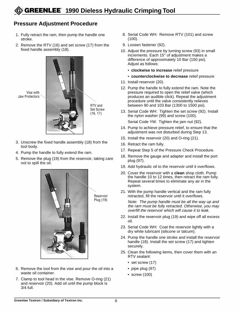
2. Remove the RTV (16) and set screw (17) from thefixed handle assembly (18).
3. Unscrew the fixed handle assembly (18) from thetool body.
4. Pump the handle to fully extend the ram.
5. Remove the plug (19) from the reservoir, taking carenot to spill the oil.
6. Remove the tool from the vise and pour the oil into awaste oil container.
7. Clamp to tool head in the vise. Remove O-ring (21)and reservoir (20). Add oil until the pump block is3/4 full.
8. Serial Code WH: Remove RTV (101) and screw(100).
9. Loosen fastener (92).
10. Adjust the pressure by turning screw (93) in smallincrements. Each 15° of adjustment makes adifference of approximately 10 Bar (150 psi).Adjust as follows:
• clockwise to increase relief pressure
• counterclockwise to decrease relief pressure11. Install reservoir (20).
12. Pump the handle to fully extend the ram. Note thepressure required to open the relief valve (whichproduces an audible click). Repeat the adjustmentprocedure until the valve consistently relievesbetween 90 and 103 Bar (1300 to 1500 psi).
13. Serial Code WH: Tighten the set screw (92). Installthe nylon washer (99) and screw (100).
Serial Code YM: Tighten the jam nut (92).
14. Pump to achieve pressure relief, to ensure that theadjustment was not disturbed during Step 13.
15. Install the reservoir (20) and O-ring (21).
16. Retract the ram fully.
17. Repeat Step 5 of the Pressure Check Procedure.
18. Remove the gauge and adapter and install the portplug (97).
19. Add hydraulic oil to the reservoir until it overflows.
20. Cover the reservoir with a clean shop cloth. Pumpthe handle 10 to 12 times, then retract the ram fully.Repeat several times to eliminate any air in thesystem.
21. With the pump handle vertical and the ram fullyretracted, fill the reservoir until it overflows.
Note: The pump handle must be all the way up andthe ram must be fully retracted. Otherwise, you mayoverfill the reservoir which will cause it to leak.
22. Install the reservoir plug (19) and wipe off all excessoil.
23. Serial Code WH: Coat the reservoir lightly with adry white lubricant (silicone or talcum).
24. Pump the handle one stroke and install the reservoirhandle (18). Install the set screw (17) and tightensecurely.
25. Clean the following items, then cover them with anRTV sealant:
• set screw (17)
• pipe plug (97)
• screw (100)
Vise withJaw Protectors
RTV andSet Screw(16, 17)
ReservoirPlug (19)
Greenlee Textron / Subsidiary of Textron Inc. 7
1990 Dieless Hydraulic Crimping Tool
Pressure Calibration Check
To perform this procedure, use Pressure Test Kit 32891.
1. Rotate the swivel head fully counterclockwise.
2. Clamp the tool head gently in a vise with thehandles upward.
3. Remove the RTV (98) and port plug (97).
4. Install the pressure gauge with the gauge adapterinto the port that the plug (97) was removed from.
5. Center a new test slug in the dies and pump thehandle. Note the pressure required to open the reliefvalve (which produces an audible click).
6. Repeat Step 5 twice, for a total of three slugs.The relief pressure for every slug should be214 to 289 Bar (3100 to 4200 psi).
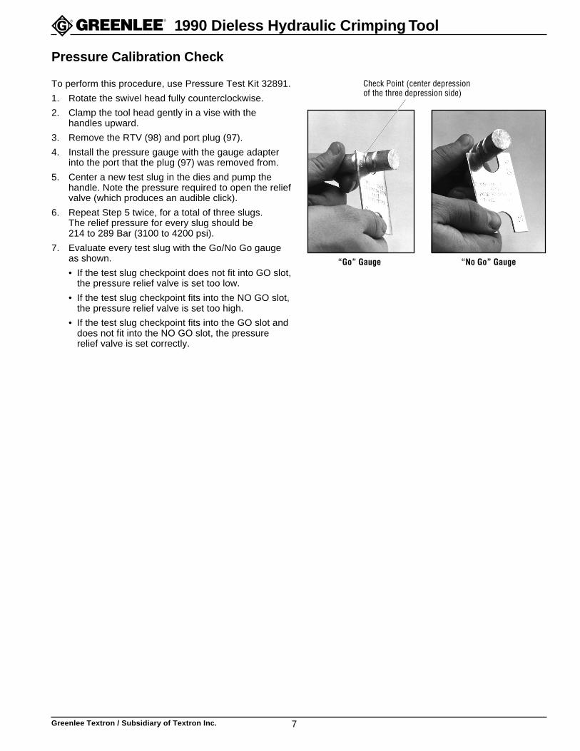
7. Evaluate every test slug with the Go/No Go gaugeas shown.
• If the test slug checkpoint does not fit into GO slot,the pressure relief valve is set too low.
• If the test slug checkpoint fits into the NO GO slot,the pressure relief valve is set too high.
• If the test slug checkpoint fits into the GO slot anddoes not fit into the NO GO slot, the pressurerelief valve is set correctly.
“Go” Gauge “No Go” Gauge
Check Point (center depressionof the three depression side)
Greenlee Textron / Subsidiary of Textron Inc. 8
1990 Dieless Hydraulic Crimping Tool
Air Purging and Oil Filling Procedure
Fill the reservoir with Exxon Univis® J26 all temperaturehydraulic oil only.
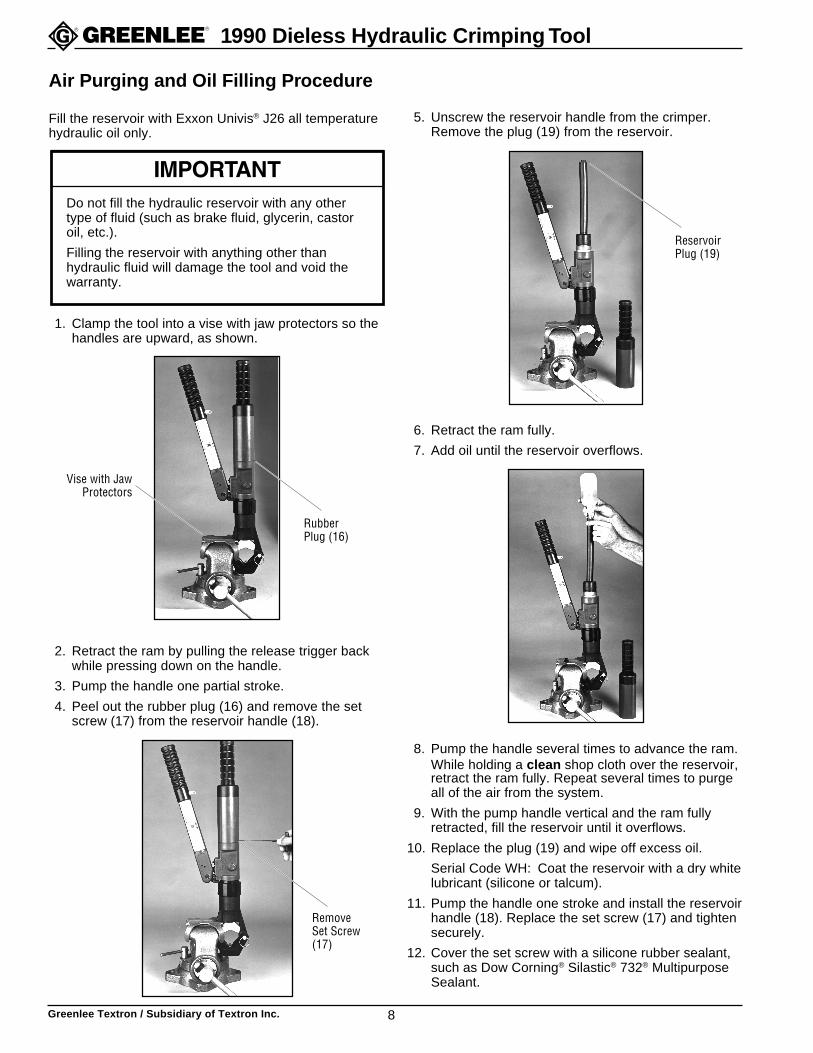
1. Clamp the tool into a vise with jaw protectors so thehandles are upward, as shown.
2. Retract the ram by pulling the release trigger backwhile pressing down on the handle.
3. Pump the handle one partial stroke.
4. Peel out the rubber plug (16) and remove the setscrew (17) from the reservoir handle (18).
Vise with JawProtectors
RubberPlug (16)
RemoveSet Screw(17)
ReservoirPlug (19)
Do not fill the hydraulic reservoir with any othertype of fluid (such as brake fluid, glycerin, castoroil, etc.).
Filling the reservoir with anything other thanhydraulic fluid will damage the tool and void thewarranty.
5. Unscrew the reservoir handle from the crimper.Remove the plug (19) from the reservoir.
6. Retract the ram fully.
7. Add oil until the reservoir overflows.
8. Pump the handle several times to advance the ram.While holding a clean shop cloth over the reservoir,retract the ram fully. Repeat several times to purgeall of the air from the system.
9. With the pump handle vertical and the ram fullyretracted, fill the reservoir until it overflows.
10. Replace the plug (19) and wipe off excess oil.
Serial Code WH: Coat the reservoir with a dry whitelubricant (silicone or talcum).
11. Pump the handle one stroke and install the reservoirhandle (18). Replace the set screw (17) and tightensecurely.
12. Cover the set screw with a silicone rubber sealant,such as Dow Corning® Silastic® 732® MultipurposeSealant.
Greenlee Textron / Subsidiary of Textron Inc. 9
1990 Dieless Hydraulic Crimping Tool
Die Replacement
This procedure is divided into two sections — one forthe fixed die (which has some steps that are particularto the serial code) and one for the movable die (whichincludes both serial codes).
Fixed Die
1. Pull the pin (23). Remove one retaining ring (27),pin (24) and fixed die assembly.
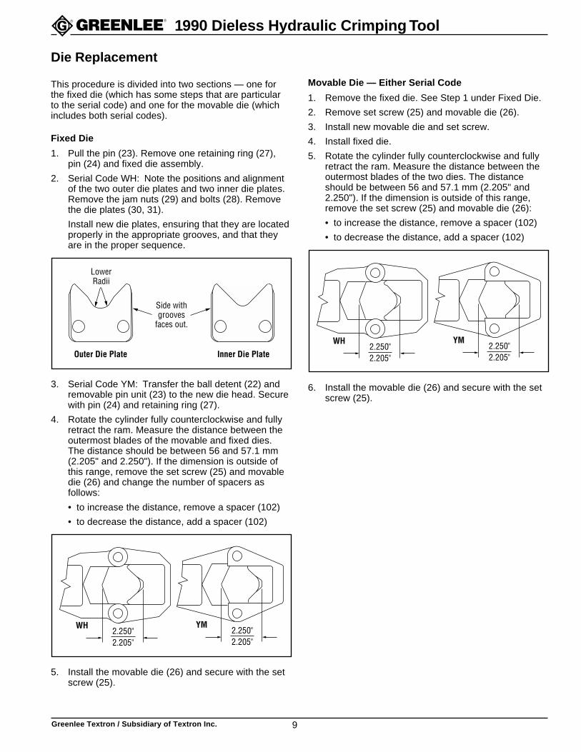
2. Serial Code WH: Note the positions and alignmentof the two outer die plates and two inner die plates.Remove the jam nuts (29) and bolts (28). Removethe die plates (30, 31).
Install new die plates, ensuring that they are locatedproperly in the appropriate grooves, and that theyare in the proper sequence.
Outer Die Plate Inner Die Plate
LowerRadii
Side withgrooves
faces out.
3. Serial Code YM: Transfer the ball detent (22) andremovable pin unit (23) to the new die head. Securewith pin (24) and retaining ring (27).
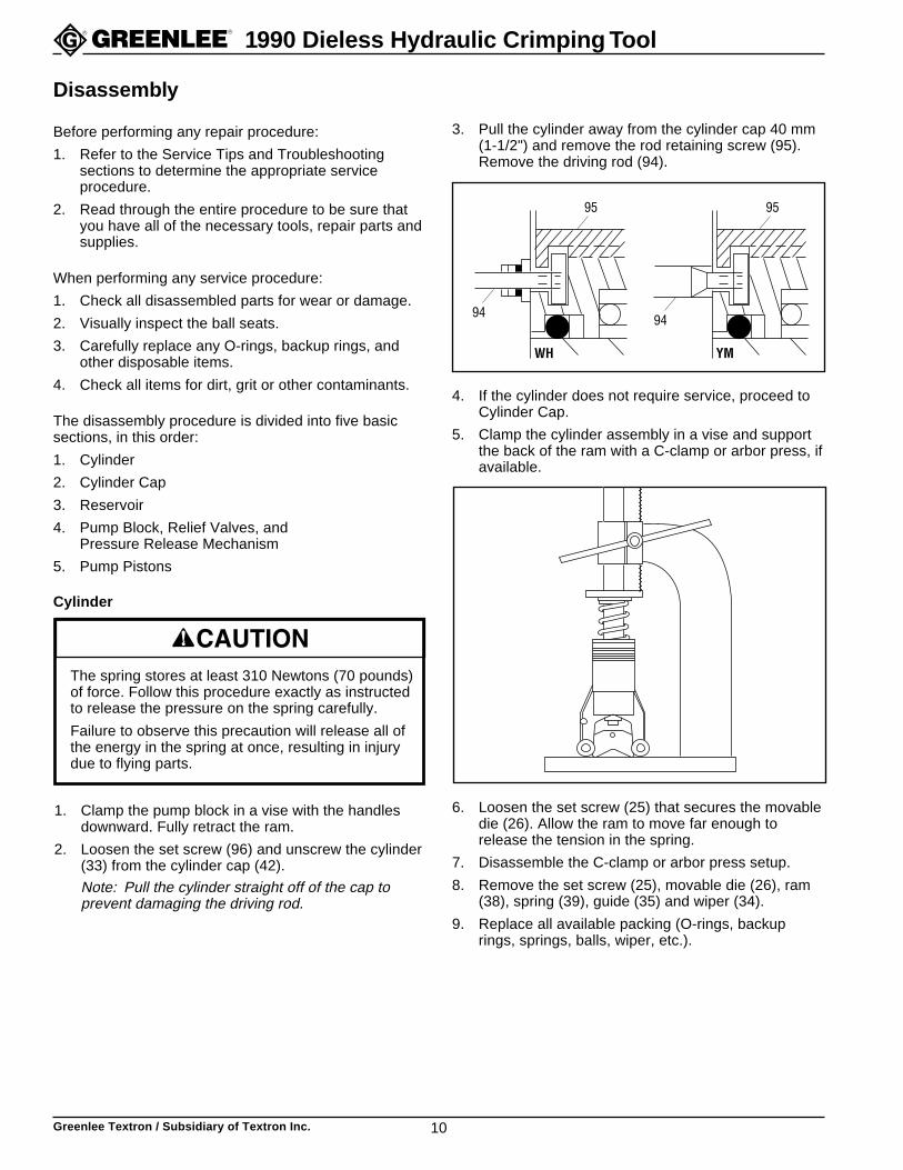
4. Rotate the cylinder fully counterclockwise and fullyretract the ram. Measure the distance between theoutermost blades of the movable and fixed dies.The distance should be between 56 and 57.1 mm(2.205" and 2.250"). If the dimension is outside ofthis range, remove the set screw (25) and movabledie (26) and change the number of spacers asfollows:
• to increase the distance, remove a spacer (102)
• to decrease the distance, add a spacer (102)
2.250"2.205"
YM2.250"2.205"
WH
5. Install the movable die (26) and secure with the setscrew (25).
Movable Die — Either Serial Code
1. Remove the fixed die. See Step 1 under Fixed Die.
2. Remove set screw (25) and movable die (26).
3. Install new movable die and set screw.
4. Install fixed die.
5. Rotate the cylinder fully counterclockwise and fullyretract the ram. Measure the distance between theoutermost blades of the two dies. The distanceshould be between 56 and 57.1 mm (2.205" and2.250"). If the dimension is outside of this range,remove the set screw (25) and movable die (26):
• to increase the distance, remove a spacer (102)
• to decrease the distance, add a spacer (102)
2.250"2.205"
YM2.250"2.205"
WH
6. Install the movable die (26) and secure with the setscrew (25).
Greenlee Textron / Subsidiary of Textron Inc. 10
1990 Dieless Hydraulic Crimping Tool
1. Clamp the pump block in a vise with the handlesdownward. Fully retract the ram.
2. Loosen the set screw (96) and unscrew the cylinder(33) from the cylinder cap (42).
Note: Pull the cylinder straight off of the cap toprevent damaging the driving rod.
Disassembly
Before performing any repair procedure:
1. Refer to the Service Tips and Troubleshootingsections to determine the appropriate serviceprocedure.
2. Read through the entire procedure to be sure thatyou have all of the necessary tools, repair parts andsupplies.
When performing any service procedure:
1. Check all disassembled parts for wear or damage.
2. Visually inspect the ball seats.
3. Carefully replace any O-rings, backup rings, andother disposable items.
4. Check all items for dirt, grit or other contaminants.
The disassembly procedure is divided into five basicsections, in this order:
1. Cylinder
2. Cylinder Cap
3. Reservoir
4. Pump Block, Relief Valves, andPressure Release Mechanism
5. Pump Pistons
Cylinder
The spring stores at least 310 Newtons (70 pounds)of force. Follow this procedure exactly as instructedto release the pressure on the spring carefully.
Failure to observe this precaution will release all ofthe energy in the spring at once, resulting in injurydue to flying parts.
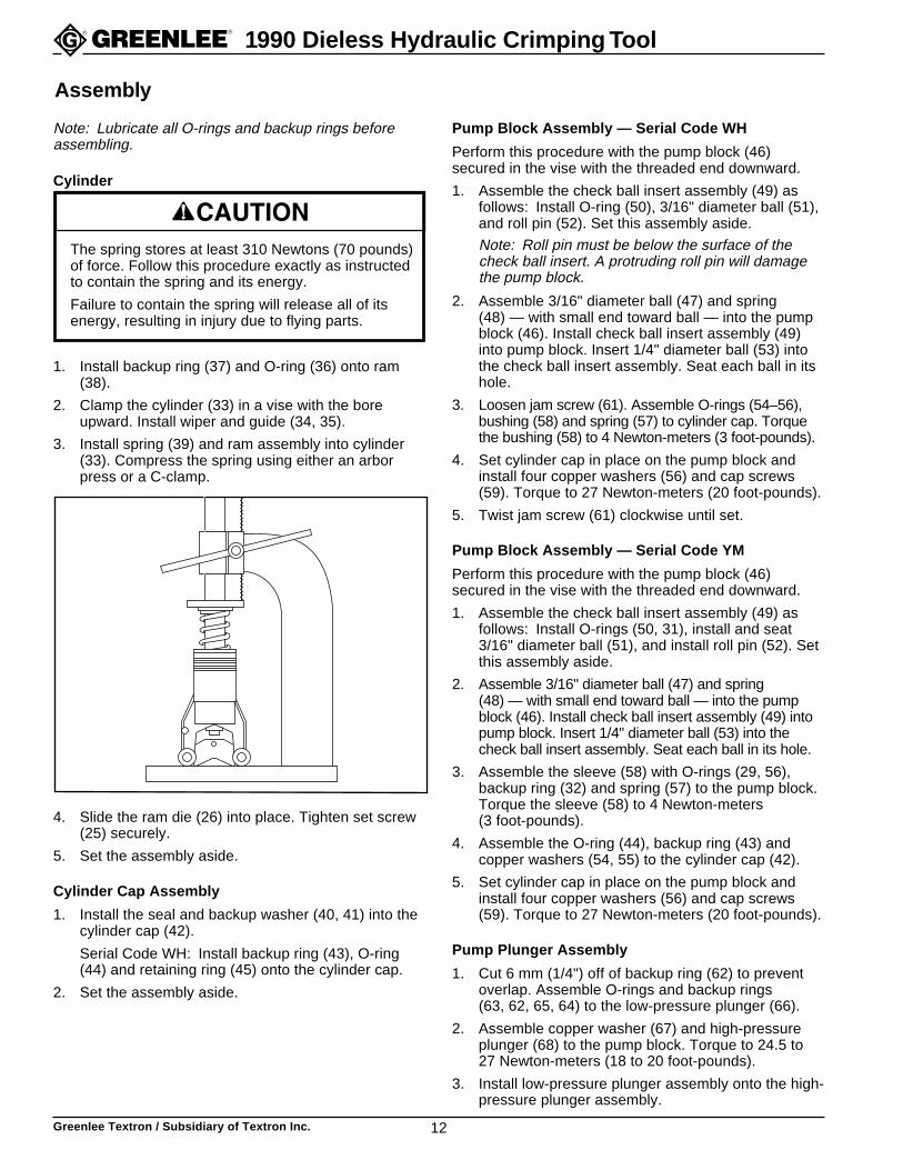
3. Pull the cylinder away from the cylinder cap 40 mm(1-1/2") and remove the rod retaining screw (95).Remove the driving rod (94).
YMWH
95
94
95
94
4. If the cylinder does not require service, proceed toCylinder Cap.
5. Clamp the cylinder assembly in a vise and supportthe back of the ram with a C-clamp or arbor press, ifavailable.
6. Loosen the set screw (25) that secures the movabledie (26). Allow the ram to move far enough torelease the tension in the spring.
7. Disassemble the C-clamp or arbor press setup.
8. Remove the set screw (25), movable die (26), ram(38), spring (39), guide (35) and wiper (34).
9. Replace all available packing (O-rings, backuprings, springs, balls, wiper, etc.).

Greenlee Textron / Subsidiary of Textron Inc. 11
1990 Dieless Hydraulic Crimping Tool
Cylinder Cap — Serial Code WH
1. Unscrew the driving rod (94) from the stepped rod(84).
2. Remove four cap screws and copper washers(59, 60). Remove the cylinder cap (42).
3. Inspect various components (43–45, 54, 55).Replace if worn or damaged.
4. Remove the check ball bushing (58), ball (53) andspring (57). Inspect the O-ring (56).
Cylinder Cap — Serial Code YM
1. Unscrew the driving rod (94) from the stepped rod(84).
Note: To service the check valves (49, 58) only,proceed to Step 4.
2. Remove four cap screws and copper washers(59, 60). Remove the cylinder cap (42).
Note: The cylinder cap must come straight off.
3. Inspect various components (43, 44, 54, 55).Replace if worn or damaged.
4. Remove the check ball sleeve (58), ball (53), spring(57), O-rings (29, 56) and backup ring (32).
Reservoir
1. Reposition the tool in the vise so that the handlesare upward. Retract the ram by pulling the releasetrigger back while pressing down the handle.
2. Peel out the RTV (16) and remove the set screw(17) from the reservoir handle (18).
3. Unscrew the reservoir handle from the pump block(46).
4. Remove the plug (19) from the reservoir (20).
5. Remove the tool from the vise and pour the oil intoa waste oil container.
6. Remove O-ring (21) and reservoir (20) from thepump block.
Pump Block, Relief Valves, andPressure Release Mechanism
1. Serial Code WH: Remove RTV (101), screw (100)and nylon washer (99). Turn set screw (93) clock-wise until it is flush with the relief valve cap (87).
2. Remove the two machine screws (91) and reliefvalve cover (90).
3. Slide out the relief valve cap (87) and remove thefollowing parts: stepped rod (84), roller guide (83),adjusting roller (88), two slides (89), valve springcap (86), valve spring (85) and relief valve plunger(81).
4. Use a spanner wrench to remove the pressure-adjusting valve body (80) and copper washer (82).
5. Disassemble the low pressure relief.
Serial Code WH: Remove the jam screw, spring,and ball (79, 78, 77).
Serial Code YM: Remove RTV, plug, spring, andball (101, 79, 78, 77).
6. Remove one retaining ring (15) and pin (14) fromhandle (5). Remove handle assembly.
7. Unscrew the pressure release body (72). Removethe ball (74) and spring (73). Remove the shaft (70)from the body (72). Inspect the O-rings (69, 71) andreplace if worn or damaged.
Serial Code YM: Also remove copper washer (30).
8. Use a T-handle Allen wrench or similar tool to pushthe check ball insert (49) out.
• Remove ball and spring (47, 48) from the pumpblock (46).
• Serial Code WH: Remove roll pin and ball(52, 51) from the insert (49).
• Serial Code YM: Remove roll pin and ball (52, 51)from the body (49).
• Inspect the O-ring (50).
Pump Piston
1. Remove one retaining ring (15) and pin (14) fromhandle (5). Remove handle assembly.
2. Remove cap screws (13) and pivot block (12).
3. Pull the low pressure plunger (66) upward and outof the pump block. Check O-rings, quad ring (SerialCode YM only) and backup rings (62–65), andreplace if worn or damaged.
4. Use an Allen wrench to unscrew the high-pressureplunger (68).
5. Remove the copper washer (67).
6. Use a T-handle Allen wrench or similar tool to pushthe check ball insert (49) out.
• Remove ball and spring (47, 48) from the pumpblock (46).
• Remove roll pin and ball (52, 51) from the insert(49).
• Inspect the O-rings (31, 50).
Disassembly (cont’d)
Greenlee Textron / Subsidiary of Textron Inc. 12
1990 Dieless Hydraulic Crimping Tool
1. Install backup ring (37) and O-ring (36) onto ram(38).
2. Clamp the cylinder (33) in a vise with the boreupward. Install wiper and guide (34, 35).
3. Install spring (39) and ram assembly into cylinder(33). Compress the spring using either an arborpress or a C-clamp.
4. Slide the ram die (26) into place. Tighten set screw(25) securely.
5. Set the assembly aside.
Cylinder Cap Assembly
1. Install the seal and backup washer (40, 41) into thecylinder cap (42).
Serial Code WH: Install backup ring (43), O-ring(44) and retaining ring (45) onto the cylinder cap.
2. Set the assembly aside.
Assembly
The spring stores at least 310 Newtons (70 pounds)of force. Follow this procedure exactly as instructedto contain the spring and its energy.
Failure to contain the spring will release all of itsenergy, resulting in injury due to flying parts.
Pump Block Assembly — Serial Code WH
Perform this procedure with the pump block (46)secured in the vise with the threaded end downward.
1. Assemble the check ball insert assembly (49) asfollows: Install O-ring (50), 3/16" diameter ball (51),and roll pin (52). Set this assembly aside.
Note: Roll pin must be below the surface of thecheck ball insert. A protruding roll pin will damagethe pump block.
2. Assemble 3/16" diameter ball (47) and spring(48) — with small end toward ball — into the pumpblock (46). Install check ball insert assembly (49)into pump block. Insert 1/4" diameter ball (53) intothe check ball insert assembly. Seat each ball in itshole.
3. Loosen jam screw (61). Assemble O-rings (54–56),bushing (58) and spring (57) to cylinder cap. Torquethe bushing (58) to 4 Newton-meters (3 foot-pounds).
4. Set cylinder cap in place on the pump block andinstall four copper washers (56) and cap screws(59). Torque to 27 Newton-meters (20 foot-pounds).
5. Twist jam screw (61) clockwise until set.
Pump Block Assembly — Serial Code YM
Perform this procedure with the pump block (46)secured in the vise with the threaded end downward.
1. Assemble the check ball insert assembly (49) asfollows: Install O-rings (50, 31), install and seat3/16" diameter ball (51), and install roll pin (52). Setthis assembly aside.
2. Assemble 3/16" diameter ball (47) and spring(48) — with small end toward ball — into the pumpblock (46). Install check ball insert assembly (49) intopump block. Insert 1/4" diameter ball (53) into thecheck ball insert assembly. Seat each ball in its hole.
3. Assemble the sleeve (58) with O-rings (29, 56),backup ring (32) and spring (57) to the pump block.Torque the sleeve (58) to 4 Newton-meters(3 foot-pounds).
4. Assemble the O-ring (44), backup ring (43) andcopper washers (54, 55) to the cylinder cap (42).
5. Set cylinder cap in place on the pump block andinstall four copper washers (56) and cap screws(59). Torque to 27 Newton-meters (20 foot-pounds).
Pump Plunger Assembly
1. Cut 6 mm (1/4") off of backup ring (62) to preventoverlap. Assemble O-rings and backup rings(63, 62, 65, 64) to the low-pressure plunger (66).
2. Assemble copper washer (67) and high-pressureplunger (68) to the pump block. Torque to 24.5 to27 Newton-meters (18 to 20 foot-pounds).
3. Install low-pressure plunger assembly onto the high-pressure plunger assembly.
Note: Lubricate all O-rings and backup rings beforeassembling.
Cylinder
Greenlee Textron / Subsidiary of Textron Inc. 13
1990 Dieless Hydraulic Crimping Tool
Pressure Release Assembly
1. Assemble O-ring (69) to pressure release shaft (70).Assemble O-ring (71) to pressure release body (72).
2. Slide shaft assembly into body assembly.
Serial Code YM: Set washer (30) into recess inpump block.
3. Install spring (73) and 9/32" ball (74) into the pumpblock.
4. Assemble pressure release assembly to pumpblock. Torque to 8 to 9.25 Newton-meters(6 to 7 foot-pounds).
Relief Valve/Pressure Control Assembly
1. Assemble low-pressure relief components:
Serial Code WH: Clamp the pump block in the visewith the threaded end upward. Install ball (77),spring (78) and jam screw (79). Turn jam screwclockwise until it is flush with the surface.
Serial Code YM: Install ball (77), spring (78) andplug (79) to the side of the pump block.
2. Set the pressure-adjusting valve body (80) on ahard surface. Insert the valve plunger (81) into thebody. Using a punch and hammer, tap the plungerwith a moderate amount of force to seat it in thebody.
Note: Using excessive force will damage the body.
3. Install the copper washer (82) and relief valve body(80) to the pump block. Torque to 27.25 to 32.5Newton-meters (20 to 24 foot-pounds).
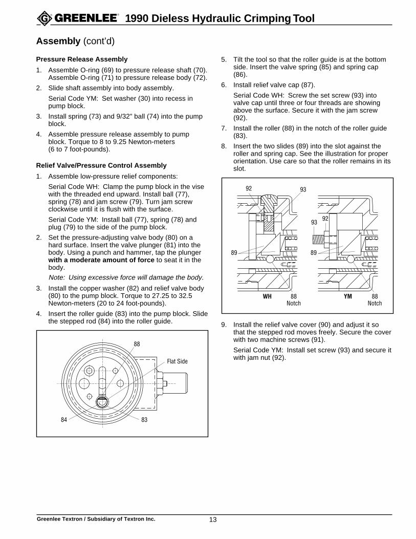
4. Insert the roller guide (83) into the pump block. Slidethe stepped rod (84) into the roller guide.
88
84 83
Flat Side
5. Tilt the tool so that the roller guide is at the bottomside. Insert the valve spring (85) and spring cap(86).
6. Install relief valve cap (87).
Serial Code WH: Screw the set screw (93) intovalve cap until three or four threads are showingabove the surface. Secure it with the jam screw(92).
7. Install the roller (88) in the notch of the roller guide(83).
8. Insert the two slides (89) into the slot against theroller and spring cap. See the illustration for properorientation. Use care so that the roller remains in itsslot.
WH
9392
88Notch
YM
9293
88Notch
8989
9. Install the relief valve cover (90) and adjust it sothat the stepped rod moves freely. Secure the coverwith two machine screws (91).
Serial Code YM: Install set screw (93) and secure itwith jam nut (92).
Assembly (cont’d)
Greenlee Textron / Subsidiary of Textron Inc. 14
1990 Dieless Hydraulic Crimping Tool
Assembly of Cylinder to Cylinder Cap
1. Push the stepped rod (84) out until the adjustmentroller (88) drops into the notch in the guide roller(88), which will produce an audible “click”.
2. Apply a threadlocking compound, such as Loctite®
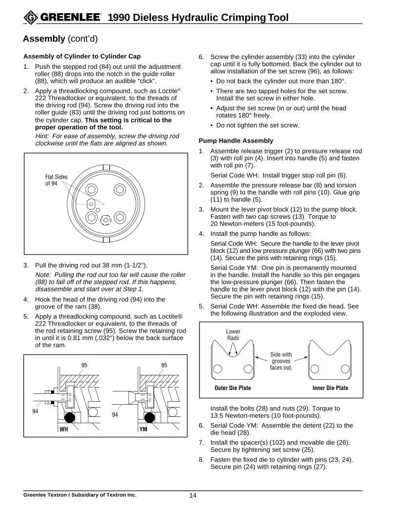
222 Threadlocker or equivalent, to the threads ofthe driving rod (94). Screw the driving rod into theroller guide (83) until the driving rod just bottoms onthe cylinder cap. This setting is critical to theproper operation of the tool.Hint: For ease of assembly, screw the driving rodclockwise until the flats are aligned as shown.
Flat Sidesof 94
3. Pull the driving rod out 38 mm (1-1/2").
Note: Pulling the rod out too far will cause the roller(88) to fall off of the stepped rod. If this happens,disassemble and start over at Step 1.
4. Hook the head of the driving rod (94) into thegroove of the ram (38).
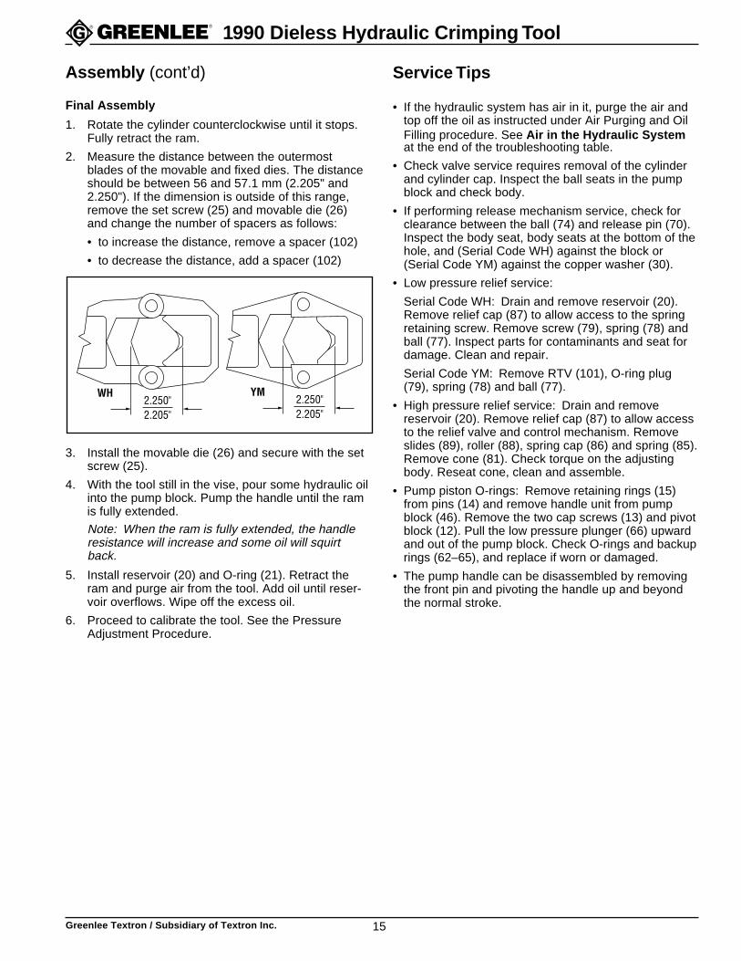
5. Apply a threadlocking compound, such as Loctite®222 Threadlocker or equivalent, to the threads ofthe rod retaining screw (95). Screw the retaining rodin until it is 0.81 mm (.032") below the back surfaceof the ram.
YMWH
95
94
95
94
6. Screw the cylinder assembly (33) into the cylindercap until it is fully bottomed. Back the cylinder out toallow installation of the set screw (96), as follows:
• Do not back the cylinder out more than 180°.• There are two tapped holes for the set screw.
Install the set screw in either hole.
• Adjust the set screw (in or out) until the headrotates 180° freely.
• Do not tighten the set screw.
Pump Handle Assembly
1. Assemble release trigger (2) to pressure release rod(3) with roll pin (4). Insert into handle (5) and fastenwith roll pin (7).
Serial Code WH: Install trigger stop roll pin (6).
2. Assemble the pressure release bar (8) and torsionspring (9) to the handle with roll pins (10). Glue grip(11) to handle (5).
3. Mount the lever pivot block (12) to the pump block.Fasten with two cap screws (13). Torque to20 Newton-meters (15 foot-pounds).
4. Install the pump handle as follows:
Serial Code WH: Secure the handle to the lever pivotblock (12) and low pressure plunger (66) with two pins(14). Secure the pins with retaining rings (15).
Serial Code YM: One pin is permanently mountedin the handle. Install the handle so this pin engagesthe low-pressure plunger (66). Then fasten thehandle to the lever pivot block (12) with the pin (14).Secure the pin with retaining rings (15).
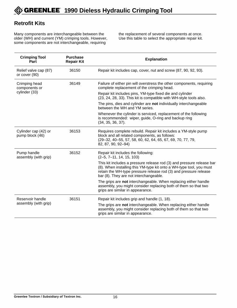
5. Serial Code WH: Assemble the fixed die head. Seethe following illustration and the exploded view.
Outer Die Plate Inner Die Plate
LowerRadii
Side withgrooves
faces out.
Install the bolts (28) and nuts (29). Torque to13.5 Newton-meters (10 foot-pounds).
6. Serial Code YM: Assemble the detent (22) to thedie head (28).
7. Install the spacer(s) (102) and movable die (26).Secure by tightening set screw (25).
8. Fasten the fixed die to cylinder with pins (23, 24).Secure pin (24) with retaining rings (27).
Assembly (cont’d)
Greenlee Textron / Subsidiary of Textron Inc. 15
1990 Dieless Hydraulic Crimping Tool
Service Tips
• If the hydraulic system has air in it, purge the air andtop off the oil as instructed under Air Purging and OilFilling procedure. See Air in the Hydraulic Systemat the end of the troubleshooting table.
• Check valve service requires removal of the cylinderand cylinder cap. Inspect the ball seats in the pumpblock and check body.
• If performing release mechanism service, check forclearance between the ball (74) and release pin (70).Inspect the body seat, body seats at the bottom of thehole, and (Serial Code WH) against the block or(Serial Code YM) against the copper washer (30).
• Low pressure relief service:
Serial Code WH: Drain and remove reservoir (20).Remove relief cap (87) to allow access to the springretaining screw. Remove screw (79), spring (78) andball (77). Inspect parts for contaminants and seat fordamage. Clean and repair.
Serial Code YM: Remove RTV (101), O-ring plug(79), spring (78) and ball (77).
• High pressure relief service: Drain and removereservoir (20). Remove relief cap (87) to allow accessto the relief valve and control mechanism. Removeslides (89), roller (88), spring cap (86) and spring (85).Remove cone (81). Check torque on the adjustingbody. Reseat cone, clean and assemble.
• Pump piston O-rings: Remove retaining rings (15)from pins (14) and remove handle unit from pumpblock (46). Remove the two cap screws (13) and pivotblock (12). Pull the low pressure plunger (66) upwardand out of the pump block. Check O-rings and backuprings (62–65), and replace if worn or damaged.
• The pump handle can be disassembled by removingthe front pin and pivoting the handle up and beyondthe normal stroke.
Assembly (cont’d)
Final Assembly
1. Rotate the cylinder counterclockwise until it stops.Fully retract the ram.
2. Measure the distance between the outermostblades of the movable and fixed dies. The distanceshould be between 56 and 57.1 mm (2.205" and2.250"). If the dimension is outside of this range,remove the set screw (25) and movable die (26)and change the number of spacers as follows:
• to increase the distance, remove a spacer (102)
• to decrease the distance, add a spacer (102)
2.250"2.205"
YM2.250"2.205"
WH
3. Install the movable die (26) and secure with the setscrew (25).
4. With the tool still in the vise, pour some hydraulic oilinto the pump block. Pump the handle until the ramis fully extended.
Note: When the ram is fully extended, the handleresistance will increase and some oil will squirtback.
5. Install reservoir (20) and O-ring (21). Retract theram and purge air from the tool. Add oil until reser-voir overflows. Wipe off the excess oil.
6. Proceed to calibrate the tool. See the PressureAdjustment Procedure.
Greenlee Textron / Subsidiary of Textron Inc. 16
1990 Dieless Hydraulic Crimping Tool
Retrofit Kits
Crimping Tool Purchase ExplanationPart Repair Kit
Relief valve cap (87) 36150 Repair kit includes cap, cover, nut and screw (87, 90, 92, 93).or cover (90)
36149 Failure of either pin will overstress the other components, requiringcomplete replacement of the crimping head.
Repair kit includes pins, YM-type fixed die and cylinder(23, 24, 28, 33). This kit is compatible with WH-style tools also.
The pins, dies and cylinder are not individually interchangeablebetween the WH and YM series.
Whenever the cylinder is serviced, replacement of the followingis recommended: wiper, guide, O-ring and backup ring(34, 35, 36, 37).
Cylinder cap (42) or 36153 Requires complete rebuild. Repair kit includes a YM-style pumppump block (46) block and all related components, as follows:
(29–32, 40–55, 57, 58, 60, 62, 64, 65, 67, 69, 70, 77, 79,82, 87, 90, 92–94)
Pump handle 36152 Repair kit includes the following:assembly (with grip) (2–5, 7–11, 14, 15, 103)
This kit includes a pressure release rod (3) and pressure release bar(8). When installing this YM-type kit onto a WH-type tool, you mustretain the WH-type pressure release rod (3) and pressure releasebar (8). They are not interchangeable.
The grips are not interchangeable. When replacing either handleassembly, you might consider replacing both of them so that twogrips are similar in appearance.
Reservoir handle 36151 Repair kit includes grip and handle (1, 18).assembly (with grip) The grips are not interchangeable. When replacing either handle
assembly, you might consider replacing both of them so that twogrips are similar in appearance.
Many components are interchangeable between theolder (WH) and current (YM) crimping tools. However,some components are not interchangeable, requiring
the replacement of several components at once.Use this table to select the appropriate repair kit.
Crimping headcomponents orcylinder (33)
Greenlee Textron / Subsidiary of Textron Inc. 17
1990 Dieless Hydraulic Crimping Tool
Problem Probable Trouble Area Recommended Service
Ram advance:1. no advance A. Air in hydraulic system {1, 2, 3, 4} A. See Air in the Hydraulic System at the end2. slow advance of this troubleshooting table.3. partial retract with each stroke B. Check valve/body {1, 2, 3} B. Reseat balls; tighten lock screw.4. erratic advance C. Release mechanism {1, 2} C. Replace O-rings, check ball/pin clearance and
reseat (69–73).D. Low pressure relief {1, 2} D. Reseat ball (77).E. High pressure relief {1, 2} E. Reseat cone (81).F. Plunger O-rings {4} F. Replace O-rings (62–68).
Slow pressure buildup:1. Handle springs back A. Discharge check ball {1} A. Reseat ball.2. No handle response B. Check balls/body {1, 2} B. Reseat balls.
C. High pressure relief {1} C. Reseat and reassemble.D. Release mechanism {1, 2} D. Check clearance and seat body.
Tool does not achieve high pressure A. Check valves/body A. Replace O-ring, reseat check balls.B. High pressure relief is not seated B. Reseat relief.C. Pressure control mechanism is C. Check the assembly of roller, slides, stepped
improperly assembled rod and adjusting screw (80–86, 88, 89).
Ram does not retract A. Wedged connector A. Free and remove connector.B. Die jammed due to misuse B. Free die. Inspect tool and replace any
damaged parts.C. Release mechanism C. Make sure ball is not over-traveling.D. Bent driving rod D. Replace rod (94).
Ram retracts partially A. Too much hydraulic fluid A. Bleed off excess oil.B. Air in hydraulic system B. See Air in the Hydraulic System at the end
of this troubleshooting table.C. Internal parts bind C. Check stepped rod and driving rod for a bind
point (84, 94).D. Dies bind D. Replace dies.
Pressure setting:1. does not change as ram advances A. Pressure adjusting screw is loose {1, 3} A. Adjust pressure and tighten screw (92, 93).2. does not change when adjusting B. Improper assembly {1, 2} B. Check the assembly of stepped rod and
screw setting is changed roller slides (84, 89).3. does not hold adjustment C. Stepped rod turned {1}. C. Turn to position. Adjust pressure.
D. Spring cap missing {1, 2} D. Replace cap (86) and adjust pressure.E. Valve cap not tight {1, 2, 3} E. Tighten cap (87) and adjust pressure.F. Driving rod disconnected {1, 3} F. Assemble. Fasten with threadlocking compound.
Internal leak at:1. low pressure relief A. Ball/cone seat damage {1, 2} A. Reseat or replace.2. high pressure relief B. Dirt or grit in the hydraulic system {1, 2} B. Drain oil; clean parts. Fill with fresh oil.3. stepped rod seals C. Missing or damaged components C. Rebuild tool.
D. Damaged O-ring {3} D. Replace O-ring and backup ring.
External leak at:1. base of reservoir handle A. Damaged reservoir {1, 2, 3} A. Replace reservoir (20).2. grip B. Damaged or missing O-ring at reservoir {1, 2, 3} B. Replace O-ring (21).3. inside reservoir handle C. Reservoir plug damaged or missing {1, 2, 3} C. Replace reservoir plug (19).4. around release plunger D. O-ring on plunger damaged or missing {4} D. Replace O-ring and backup ring (64, 65).5. between pump block and E. Loose cylinder cap {5} E. Tighten screws (59) to proper torque.
cylinder cap F. O-rings (WH) or copper washers (YM) damaged {5} F. Replace components (43, 44, 45) or (60).6. around cylinder near cap G. Damaged cylinder seal in cap {6} G. Replace O-ring and backup ring (40, 41)7. movable die H. Damaged O-rings and backup ring on ram {7} H. Replace O-ring and backup ring (36, 37).
I. Damaged ram {7} I. Replace ram. Check cylinder bore for damage.
Air in the Hydraulic System A. Improper fill and purge procedure A. Fill reservoir and purge air.B. Loose or missing reservoir plug B. Replace plug, or install plug properly.C. Damaged O-ring on low pressure plunger C. Replace O-ring and backup ring.D. Damaged reservoir D. Replace reservoir.E. Damaged or missing O-ring on reservoir E. Replace O-ring.F. Reservoir is underfilled F. Fill reservoir and purge air.
Troubleshooting
This table lists some of the most common problems(first column). The probable trouble areas (secondcolumn) contain numbers in brackets { } relating to the
problems listed in the first column. Recommendedservice procedures are provided (third column).
Greenlee Textron / Subsidiary of Textron Inc. 18
1990 Dieless Hydraulic Crimping Tool
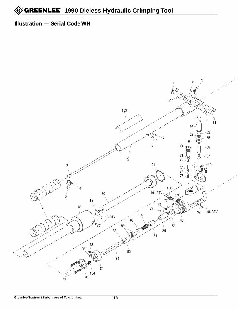
8
10
1410
66
72
7
6
70
12
5
3
2
4
19
20
18
17 16 RTV
8889
84
83
46
13
68
64
62
99
100
7778
79
21
82
85
9392
91
915
8081
86
697473
71
6563
67
101 RTV
98 RTV97
103
1
87104
90
Illustration — Serial Code WH
Greenlee Textron / Subsidiary of Textron Inc. 19
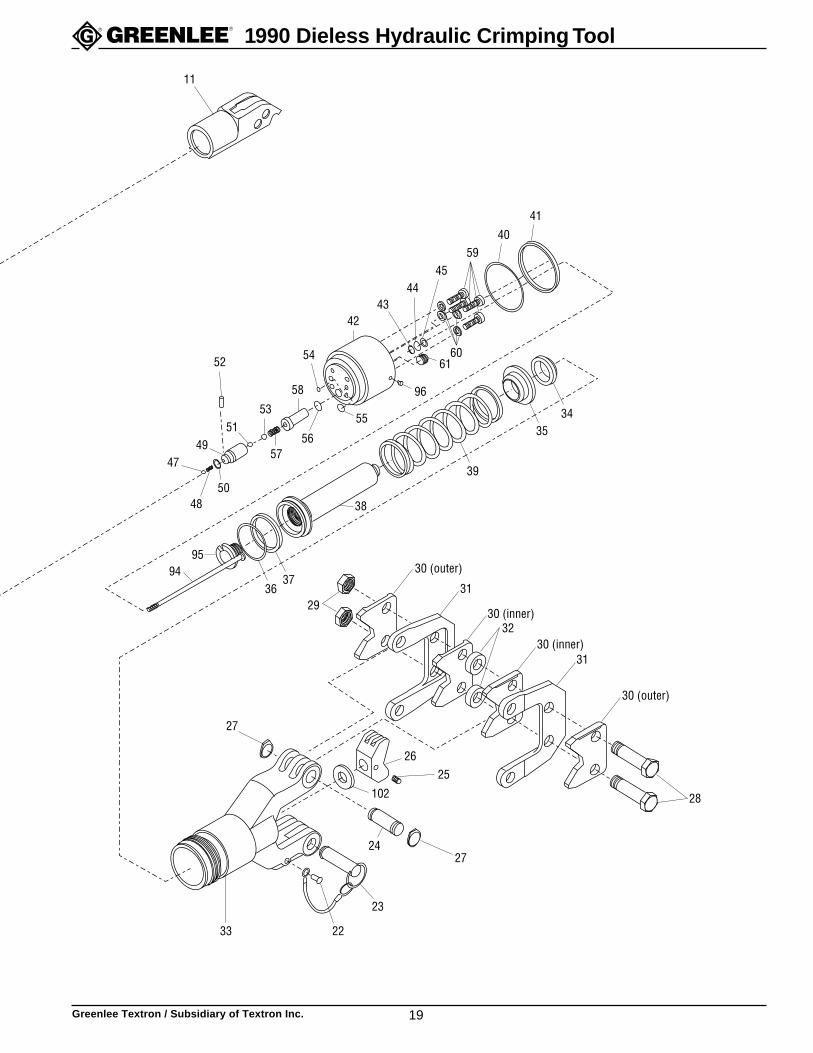
1990 Dieless Hydraulic Crimping Tool
11
95
49
29
58
38
31
42
59
32
31
28
24
26
23
2233
27
27
25
37
6061
4443
45
40
41
54
5657
5351
52
5048
47
30 (outer)
30 (inner)
30 (inner)
30 (outer)
9436
55
96
39
3534
102
Greenlee Textron / Subsidiary of Textron Inc. 20
1990 Dieless Hydraulic Crimping Tool
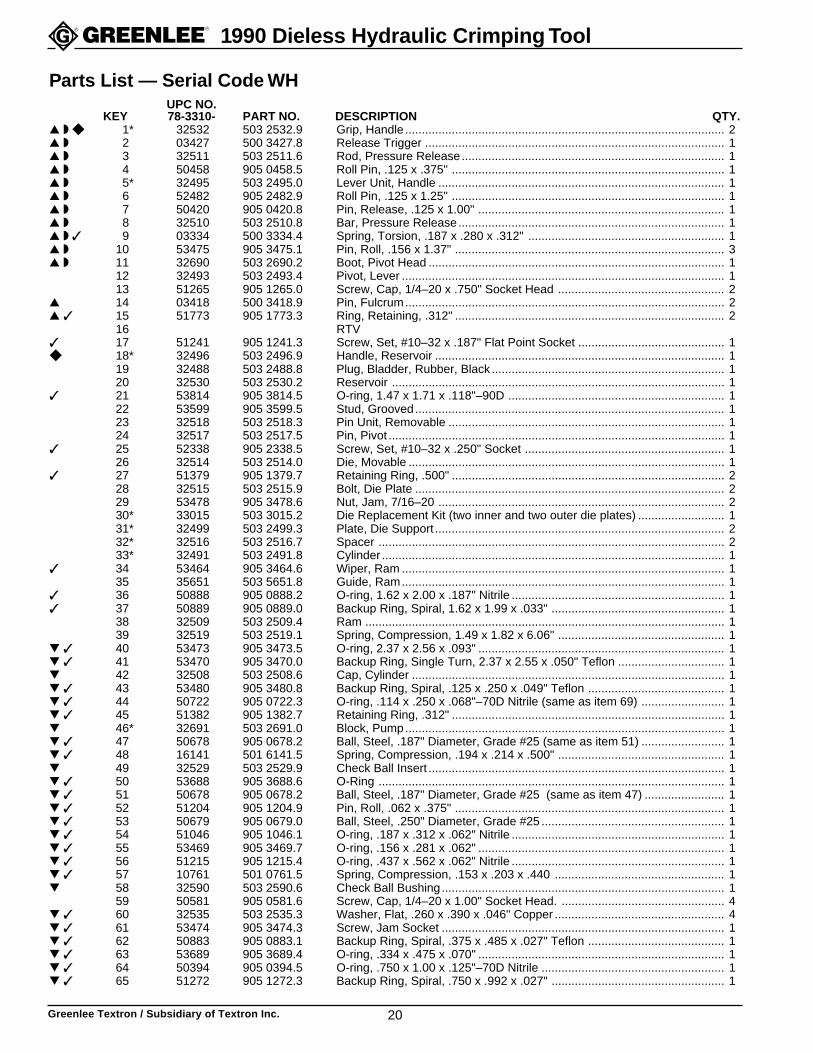
Parts List — Serial Code WHUPC NO.
KEY 78-3310- PART NO. DESCRIPTION QTY.▲ ◗ ◆ 1* 32532 503 2532.9 Grip, Handle ................................................................................................ 2▲ ◗ 2 03427 500 3427.8 Release Trigger .......................................................................................... 1▲ ◗ 3 32511 503 2511.6 Rod, Pressure Release............................................................................... 1▲ ◗ 4 50458 905 0458.5 Roll Pin, .125 x .375" .................................................................................. 1▲ ◗ 5* 32495 503 2495.0 Lever Unit, Handle ...................................................................................... 1▲ ◗ 6 52482 905 2482.9 Roll Pin, .125 x 1.25" .................................................................................. 1▲ ◗ 7 50420 905 0420.8 Pin, Release, .125 x 1.00" .......................................................................... 1▲ ◗ 8 32510 503 2510.8 Bar, Pressure Release................................................................................ 1▲ ◗ ✓ 9 03334 500 3334.4 Spring, Torsion, .187 x .280 x .312" ........................................................... 1▲ ◗ 10 53475 905 3475.1 Pin, Roll, .156 x 1.37" ................................................................................. 3▲ ◗ 11 32690 503 2690.2 Boot, Pivot Head ......................................................................................... 1
12 32493 503 2493.4 Pivot, Lever ................................................................................................. 113 51265 905 1265.0 Screw, Cap, 1/4–20 x .750" Socket Head .................................................. 2
▲ 14 03418 500 3418.9 Pin, Fulcrum................................................................................................ 2▲ ✓ 15 51773 905 1773.3 Ring, Retaining, .312" ................................................................................. 2
16 RTV✓ 17 51241 905 1241.3 Screw, Set, #10–32 x .187" Flat Point Socket ............................................ 1◆ 18* 32496 503 2496.9 Handle, Reservoir ....................................................................................... 1
19 32488 503 2488.8 Plug, Bladder, Rubber, Black ...................................................................... 120 32530 503 2530.2 Reservoir .................................................................................................... 1
✓ 21 53814 905 3814.5 O-ring, 1.47 x 1.71 x .118"–90D ................................................................. 122 53599 905 3599.5 Stud, Grooved............................................................................................. 123 32518 503 2518.3 Pin Unit, Removable ................................................................................... 124 32517 503 2517.5 Pin, Pivot ..................................................................................................... 1
✓ 25 52338 905 2338.5 Screw, Set, #10–32 x .250" Socket ............................................................ 126 32514 503 2514.0 Die, Movable ............................................................................................... 1
✓ 27 51379 905 1379.7 Retaining Ring, .500" .................................................................................. 228 32515 503 2515.9 Bolt, Die Plate ............................................................................................. 229 53478 905 3478.6 Nut, Jam, 7/16–20 ...................................................................................... 230* 33015 503 3015.2 Die Replacement Kit (two inner and two outer die plates) .......................... 131* 32499 503 2499.3 Plate, Die Support ....................................................................................... 232* 32516 503 2516.7 Spacer ........................................................................................................ 233* 32491 503 2491.8 Cylinder ....................................................................................................... 1
✓ 34 53464 905 3464.6 Wiper, Ram ................................................................................................. 135 35651 503 5651.8 Guide, Ram................................................................................................. 1
✓ 36 50888 905 0888.2 O-ring, 1.62 x 2.00 x .187" Nitrile ................................................................ 1✓ 37 50889 905 0889.0 Backup Ring, Spiral, 1.62 x 1.99 x .033" .................................................... 1
38 32509 503 2509.4 Ram ............................................................................................................ 139 32519 503 2519.1 Spring, Compression, 1.49 x 1.82 x 6.06" .................................................. 1
▼ ✓ 40 53473 905 3473.5 O-ring, 2.37 x 2.56 x .093" .......................................................................... 1▼ ✓ 41 53470 905 3470.0 Backup Ring, Single Turn, 2.37 x 2.55 x .050" Teflon ................................ 1▼ 42 32508 503 2508.6 Cap, Cylinder .............................................................................................. 1▼ ✓ 43 53480 905 3480.8 Backup Ring, Spiral, .125 x .250 x .049" Teflon ......................................... 1▼ ✓ 44 50722 905 0722.3 O-ring, .114 x .250 x .068"–70D Nitrile (same as item 69) ......................... 1▼ ✓ 45 51382 905 1382.7 Retaining Ring, .312" .................................................................................. 1▼ 46* 32691 503 2691.0 Block, Pump................................................................................................ 1▼ ✓ 47 50678 905 0678.2 Ball, Steel, .187" Diameter, Grade #25 (same as item 51) ......................... 1▼ ✓ 48 16141 501 6141.5 Spring, Compression, .194 x .214 x .500" .................................................. 1▼ 49 32529 503 2529.9 Check Ball Insert ......................................................................................... 1▼ ✓ 50 53688 905 3688.6 O-Ring ........................................................................................................ 1▼ ✓ 51 50678 905 0678.2 Ball, Steel, .187" Diameter, Grade #25 (same as item 47) ........................ 1▼ ✓ 52 51204 905 1204.9 Pin, Roll, .062 x .375" ................................................................................. 1▼ ✓ 53 50679 905 0679.0 Ball, Steel, .250" Diameter, Grade #25 ....................................................... 1▼ ✓ 54 51046 905 1046.1 O-ring, .187 x .312 x .062" Nitrile ................................................................ 1▼ ✓ 55 53469 905 3469.7 O-ring, .156 x .281 x .062" .......................................................................... 1▼ ✓ 56 51215 905 1215.4 O-ring, .437 x .562 x .062" Nitrile ................................................................ 1▼ ✓ 57 10761 501 0761.5 Spring, Compression, .153 x .203 x .440 ................................................... 1▼ 58 32590 503 2590.6 Check Ball Bushing..................................................................................... 1
59 50581 905 0581.6 Screw, Cap, 1/4–20 x 1.00" Socket Head. ................................................. 4▼ ✓ 60 32535 503 2535.3 Washer, Flat, .260 x .390 x .046" Copper ................................................... 4▼ ✓ 61 53474 905 3474.3 Screw, Jam Socket ..................................................................................... 1▼ ✓ 62 50883 905 0883.1 Backup Ring, Spiral, .375 x .485 x .027" Teflon ......................................... 1▼ ✓ 63 53689 905 3689.4 O-ring, .334 x .475 x .070" .......................................................................... 1▼ ✓ 64 50394 905 0394.5 O-ring, .750 x 1.00 x .125"–70D Nitrile ....................................................... 1▼ ✓ 65 51272 905 1272.3 Backup Ring, Spiral, .750 x .992 x .027" .................................................... 1
Greenlee Textron / Subsidiary of Textron Inc. 21
1990 Dieless Hydraulic Crimping Tool
Parts List — Serial Code WH (cont’d)
66 32503 503 2503.5 Plunger, Lo Pressure .................................................................................. 1▼ ✓ 67 53477 905 3477.8 Washer, Flat, .156 x .250 x .046" Copper ................................................... 1
68 32504 503 2504.3 Plunger, Hi Pressure................................................................................... 1▼ ✓ 69 50722 905 0722.3 O-ring, .114 x .250 x .068"–70D Nitrile (same as item 44) ......................... 1
70 32507 503 2507.8 Shaft, Pressure Release ............................................................................. 1▼ ✓ 71 50168 905 0168.3 O-ring, .364 x .500 x .068"–90D Nitrile ....................................................... 1
72 32506 503 2506.0 Body, Pressure Release ............................................................................. 1✓ 73 32534 503 2534.5 Spring, Compression, .164 x .240 x .750" .................................................. 1✓ 74 50436 905 0436.4 Ball, Steel, .281 Diameter, Grade #25 ........................................................ 1▼ ✓ 77 50452 905 0452.6 Ball, Steel, .218 Diameter, Grade #25 ........................................................ 1✓ 78 13263 501 3263.6 Spring, Compression, .184 x .242 x .815" .................................................. 1▼ ✓ 79 51337 905 1337.1 Screw, Jam, 5/16–24 x .156 Socket ........................................................... 1✖ 80 32523 503 2523.0 Body, Pressure-Adjusting Valve ................................................................. 1✖ 81 32789 503 2789.5 Plunger, Valve ............................................................................................ 1✖ ▼ ✓ 82 03421 500 3421.9 Washer, Flat, .440 x .687 x .064" Copper ................................................... 1
83 32558 503 2558.2 Guide, Roller ............................................................................................... 184 32562 503 2562.0 Rod, Stepped .............................................................................................. 1
✖ ✓ 85 32572 503 2572.8 Spring, Compression, .178 x .322 x .875" .................................................. 1✖ 86 32561 503 2561.2 Cap, Valve Spring ....................................................................................... 1● ▼ 87* 32556 503 2556.6 Cap, Relief Valve ........................................................................................ 1
88 32564 503 2564.7 Roller, Valve Adjustment, .197 x .247" ....................................................... 189 32559 503 2559.0 Slide, Moving .............................................................................................. 2
● ▼ 90* 32591 503 2591.4 Cover, Relief Valve ..................................................................................... 1✓ 91 51462 905 1462.9 Screw, Machine, #10–32 x 1.25" Round Head ........................................... 2● ▼ ✓ 92 51286 905 1286.3 Screw, Jam, #8–32 x .109 Socket .............................................................. 1● ▼ ✓ 93 53600 905 3600.2 Screw, Set, 1/4–20 x .437 Flat Point Socket .............................................. 1▼ 94 32563 503 2563.9 Rod Unit, Driving......................................................................................... 1
95 32557 503 2557.4 Screw, Rod Retaining ................................................................................. 1✓ 96 51245 905 1245.6 Screw, Set, 1/4-20 x .250" Flat Point Socket .............................................. 1▼ 97 50824 905 0824.6 Plug, Pipe, 1/16" ......................................................................................... 1
98 RTV✓ 99 53482 905 3482.4 Washer, Flat, .259 x .393 x .062" Nylon ..................................................... 1✓ 100 53481 905 3481.6 Screw, Cap, 1/4–20 x .250 Fillister Head ................................................... 1
101 RTV102 33730 503 3730.0 Spacer, .549 x .997 x .025" Stainless Steel ................................................ **
▲ 103 35462 503 5462.0 Decal, Warning ........................................................................................... 1✓ 104 22726 502 2726.2 Filter, Oil ..................................................................................................... 1*No longer available. See the list of kits at the end of this parts list to retrofit the tool.
**Quantity of one or two, if necessary. To determine if this item is necessary, see Die Replacement procedure.
Decals 32792 503 2792.5 Decal, Identification35463 503 5463.9 Decal, Connector Chart35757 503 5757.3 Decal, Instruction35758 503 5758.1 Decal, Pressure Check Procedure35759 503 5759.0 Decal, Safety06233 500 6233.6 Decal, Safety Lid Liner06243 500 6243.3 Decal, Operating Instructions
Accessory 32791 503 2791.7 Case, Carrying
Repair Kits, Retrofit Kits, and SuppliesReplace worn or broken items with newer YM-style components. Some WH-style components are no longer available;corresponding retrofit kits are marked “Required”.
32891 503 2891.3 Slug Test Kit (includes one Go/No Go Gauge and 30 test slugs)✓ 33013 503 3013.6 Hydraulic Repair Kit✖ 33737 503 3737.8 Relief Valve Repair Kit (Recommended)◗ 35671 503 5671.2 Pump Handle Unit (Required)
● 36150 503 6150.3 Valve Cap and Cover Repair/Retrofit Kit (Required)◆ 36151 503 6151.1 Reservoir Handle Repair/Retrofit Kit (Required)▲ 36152 503 6152.0 Pump Handle Repair/Retrofit Kit (Required)▼ 36153 503 6153.8 Pump Block Repair/Retrofit Kit (Required)
Replace worn or broken components with identical WH-style components:✓ 33013 503 3013.6 Hydraulic Repair Kit
33015 503 3015.2 Die Replacement Kit (includes two inner dies and two outer dies)
UPC NO.KEY 78-3310- PART NO. DESCRIPTION QTY.

Greenlee Textron / Subsidiary of Textron Inc. 22
1990 Dieless Hydraulic Crimping Tool
98 RTV46
8988
8384
87
90
16 RTV
18
1
20
19
5
7
103
8
10
66
101 RTV72 68
7013
97
30
73
74
69
82
85
104
91
9392
17
21 777879
71
64
62 63
65
67
15
9
8081
86
Glue grip (11) to handle (5).
11
12
Illustration — Serial Code YM
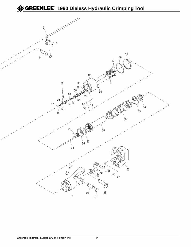
Greenlee Textron / Subsidiary of Textron Inc. 23
1990 Dieless Hydraulic Crimping Tool
59
42
58
49
3
42
14 4140
60
444355
56
54
3252
5351
5731
5048
47
15
3324 23
102
26
22
2827
27
25
95
34
41
29
96
35
39
38
3736
94
Greenlee Textron / Subsidiary of Textron Inc. 24
1990 Dieless Hydraulic Crimping Tool
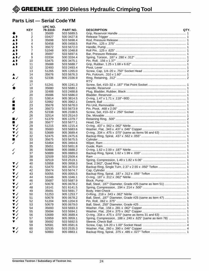
Parts List — Serial Code YMUPC NO.
KEY 78-3310- PART NO. DESCRIPTION QTY.◆ 1 35689 503 5689.5 Grip, Reservoir Handle ............................................................................... 1▲ ◗ 2 03427 500 3427.8 Release Trigger .......................................................................................... 1▲ ◗ 3 35698 503 5698.4 Rod, Pressure Release............................................................................... 1▲ ◗ 4 50458 905 0458.5 Roll Pin, .125 x .375" .................................................................................. 1▲ ◗ 5 35672 503 5672.0 Handle, Pump ............................................................................................. 1▲ ◗ 7 51048 905 1048.8 Roll Pin, .125 x .625" .................................................................................. 1▲ ◗ 8 35697 503 5697.6 Bar, Pressure Release................................................................................ 1▲ ◗ ✓ 9 03334 500 3334.4 Spring, Torsion, .187 x .280 x .312" ........................................................... 1▲ ◗ 10 53475 905 3475.1 Pin, Roll, .156 x 1.37" ................................................................................. 2▲ ◗ 11 35688 503 5688.7 Grip, Rubber, 1.25 x 1.68 x 6.62" ............................................................... 1
12 32493 503 2493.4 Pivot, Lever ................................................................................................. 113 51265 905 1265.0 Screw, Cap, 1/4–20 x .750" Socket Head .................................................. 2
▲ 14 35676 503 5676.3 Pin, Fulcrum, .310 x 1.60" .......................................................................... 1▲ ✓ 15 52336 905 2336.9 Ring, Retaining, .312" ................................................................................. 2
16 RTV✓ 17 51241 905 1241.3 Screw, Set, #10–32 x .187" Flat Point Socket ............................................ 1◆ 18 35680 503 5680.1 Handle, Reservoir ....................................................................................... 1
19 32488 503 2488.8 Plug, Bladder, Rubber, Black...................................................................... 120 35686 503 5686.0 Bladder, Reservoir ...................................................................................... 1
✓ 21 53814 905 3814.5 O-ring, 1.47 x 1.71 x .118"–90D ................................................................. 1■ 22 53962 905 3962.1 Detent, Ball ................................................................................................. 1■ 23 35678 503 5678.0 Pin Unit, Removable ................................................................................... 1■ 24 35673 503 5673.9 Pin, Pivot, .468 x 2.05" ............................................................................... 1✓ 25 52338 905 2338.5 Screw, Set, #10–32 x .250" Socket ............................................................ 1
26 32514 503 2514.0 Die, Movable ............................................................................................... 1■ ✓ 27 51379 905 1379.7 Retaining Ring, .500" .................................................................................. 2■ 28 35677 503 5677.1 Head, Die .................................................................................................... 1▼ ✓ 29 51215 905 1215.4 O-ring, .437 x .562 x .062" Nitrile ................................................................ 1▼ ✓ 30 35683 503 5683.6 Washer, Flat, .343 x .437 x .046" Copper ................................................... 1▼ ✓ 31 53689 905 3689.4 O-ring, .334 x .475 x .070" (same as items 56 and 63) .............................. 1▼ ✓ 32 52475 905 2475.6 Backup Ring, Spiral, .437 x .562 x .055" .................................................... 1■ 33 35675 503 5675.5 Cylinder ....................................................................................................... 1✓ 34 53464 905 3464.6 Wiper, Ram ................................................................................................. 1
35 35651 503 5651.8 Guide, Ram................................................................................................. 1✓ 36 50888 905 0888.2 O-ring, 1.62 x 2.00 x .187" Nitrile ................................................................ 1✓ 37 50889 905 0889.0 Backup Ring, Spiral, 1.62 x 1.99 x .033" .................................................... 1
38 32509 503 2509.4 Ram ............................................................................................................ 139 32519 503 2519.1 Spring, Compression, 1.49 x 1.82 x 6.06" .................................................. 1
▼ ✓ 40 53958 905 3958.3 Seal, 2.562", Quad Ring ............................................................................. 1▼ ✓ 41 53470 905 3470.0 Backup Ring, Single Turn, 2.37 x 2.55 x .050" Teflon ................................ 1▼ 42 35674 503 5674.7 Cap, Cylinder .............................................................................................. 1▼ ✓ 43 50055 905 0055.5 Backup Ring, Spiral, .187 x .312 x .055" Teflon ......................................... 1▼ ✓ 44 51046 905 1046.1 O-ring, .187 x .312 x .062" Nitrile ................................................................ 1▼ 46 35687 503 5687.9 Block, Pump................................................................................................ 1▼ ✓ 47 50678 905 0678.2 Ball, Steel, .187" Diameter, Grade #25 (same as item 51) ......................... 1▼ ✓ 48 16141 501 6141.5 Spring, Compression, .194 x .214 x .500" .................................................. 1▼ 49 35691 503 5691.7 Body, Inlet Check........................................................................................ 1▼ ✓ 50 51253 905 1253.7 O-Ring, .218 x .343 x .062" Nitrile .............................................................. 1▼ ✓ 51 50678 905 0678.2 Ball, Steel, .187" Diameter, Grade #25 (same as item 47) ......................... 1▼ ✓ 52 51204 905 1204.9 Pin, Roll, .062 x .375" ................................................................................. 1▼ ✓ 53 50679 905 0679.0 Ball, Steel, .250" Diameter, Grade #25 ....................................................... 1▼ ✓ 54 35693 503 5693.3 Washer, Flat, .156 x .281 x .062" Copper ................................................... 1▼ ✓ 55 35694 503 5694.1 Washer, Flat, .204 x .375 x .062" Copper ................................................... 1▼ ✓ 56 53689 905 3689.4 O-ring, .334 x .475 x .070" (same as items 31 and 63) .............................. 1▼ ✓ 57 53959 905 3959.1 Spring, Compression, .188 x .240 x .625" (same as item 78) .................... 1▼ 58 35692 503 5692.5 Sleeve, Check Ball ...................................................................................... 1
59 50581 905 0581.6 Screw, Cap, 1/4-20 x 1.00" Socket Head. .................................................. 4▼ ✓ 60 32535 503 2535.3 Washer, Flat, .260 x .390 x .046" Copper ................................................... 4▼ ✓ 62 50883 905 0883.1 Backup Ring, Spiral, .375 x .485 x .027" Teflon ......................................... 1
Greenlee Textron / Subsidiary of Textron Inc. 25
1990 Dieless Hydraulic Crimping Tool
Parts List — Serial Code YM (cont’d)UPC NO.
KEY 78-3310- PART NO. DESCRIPTION QTY.▼ ✓ 63 53689 905 3689.4 O-ring, .334 x .475 x .070" (same as items 31 and 56) .............................. 1▼ ✓ 64 53957 905 3957.5 Seal, 1.00", Quad Ring ............................................................................... 1▼ ✓ 65 51272 905 1272.3 Backup Ring, Spiral, .750 x .992 x .027" .................................................... 1
66 32503 503 2503.5 Plunger, Lo Pressure .................................................................................. 1▼ ✓ 67 53477 905 3477.8 Washer, Flat, .156 x .250 x .046" Copper ................................................... 1
68 32504 503 2504.3 Plunger, Hi Pressure................................................................................... 1▼ ✓ 69 50722 905 0722.3 O-ring, .114 x .250 x .068"–70D Nitrile ....................................................... 1
70 35690 503 5690.9 Shaft, Pressure Release ............................................................................. 1▼ ✓ 71 50168 905 0168.3 O-ring, .364 x .500 x .068"–90D Nitrile ....................................................... 1
72 35696 503 5696.8 Body, Pressure Release ............................................................................. 1✓ 73 32534 503 2534.5 Spring, Compression, .164 x .240 x .750" .................................................. 1✓ 74 50436 905 0436.4 Ball, Steel, .281 Diameter, Grade #25 ........................................................ 1▼ ✓ 77 50452 905 0452.6 Ball, Steel, .218 Diameter, Grade #25 ........................................................ 1✓ 78 53959 905 3959.1 Spring, Compression, .188 x .240 x .625" (same as item 57) .................... 1▼ ✓ 79 53960 905 3960.5 Plug, O-Ring, 5/16-24 x .380" ..................................................................... 1✖ 80 32523 503 2523.0 Body, Pressure-Adjusting Valve ................................................................. 1✖ 81 32789 503 2789.5 Plunger, Valve ............................................................................................ 1✖ ▼ ✓ 82 03421 500 3421.9 Washer, Flat, .440 x .687 x .064" Copper ................................................... 1
83 35699 503 5699.2 Guide, Roller ............................................................................................... 184 32562 503 2562.0 Rod, Stepped .............................................................................................. 1
✖ ✓ 85 32572 503 2572.8 Spring, Compression, .178 x .322 x .875" .................................................. 1✖ 86 35695 503 5695.0 Cap, Valve Spring, .343 x .432 x .435" ....................................................... 1● ▼ 87 35682 503 5682.8 Cap, Relief Valve ........................................................................................ 1
88 32564 503 2564.7 Roller, Valve Adjustment, .197 x .247" ....................................................... 189 32559 503 2559.0 Slide, Moving .............................................................................................. 2
● ▼ 90 35681 503 5681.0 Plate, Valve................................................................................................. 1✓ 91 51462 905 1462.9 Screw, Machine, #10–32 x 1.25" Round Head ........................................... 2● ▼ ✓ 92 51686 905 1686.9 Nut, Hex, #10–32 Full ................................................................................. 1● ▼ ✓ 93 53961 905 3961.3 Screw, #10–32, Socket Set ........................................................................ 1▼ 94 35684 503 5684.4 Rod Unit, Driving......................................................................................... 1
95 32557 503 2557.4 Screw, Rod Retaining ................................................................................. 1✓ 96 51245 905 1245.6 Screw, Set, 1/4-20 x .250" Flat Point Socket .............................................. 1▼ ✓ 97 53960 905 3960.5 Plug, O-Ring, 5/16-24 x .380" ..................................................................... 1
98 RTV101 RTV102 33730 503 3730.0 Spacer, .549 x .997 x .025" Stainless Steel ................................................. *
▲ 103 35462 503 5462.0 Decal, Warning ........................................................................................... 1✓ 104 22726 502 2726.2 Filter, Oil ..................................................................................................... 1*Quantity of one or two, if necessary. To determine if this item is necessary, see Die Replacement procedure.
Decals 32792 503 2792.5 Decal, Identification .................................................................................... 135463 503 5463.9 Decal, Connector Chart .............................................................................. 106233 500 6233.6 Decal, Safety Lid Liner ................................................................................ 106243 500 6243.3 Decal, Operating Inst. ................................................................................. 1
Accessory 32791 503 2791.7 Case, Carrying ............................................................................................ 1
Repair Kits and Supplies32891 503 2891.3 Slug Test Kit (includes one Go/No Go Gauge and 30 test slugs)
✓ 33013 503 3013.6 Hydraulic Repair Kit✖ 33737 503 3737.8 Relief Valve Repair Kit◗ 35671 503 5671.2 Pump Handle Unit
■ 36149 503 6149.0 Cylinder and Die Head Repair Kit● 36150 503 6150.3 Valve Cap and Cover Repair Kit◆ 36151 503 6151.1 Reservoir Handle Repair Kit▲ 36152 503 6152.0 Pump Handle Repair Kit▼ 36153 503 6153.8 Pump Block Repair Kit

Greenlee Textron / Subsidiary of Textron Inc.4455 Boeing Drive, Rockford, IL 61109-2988 USA
Customer Service (International): 815/397-7070 • Fax: 815/397-9247Customer Service (North America): 800/435-0786 • Fax: 800/451-2632, 815/397-1865
Canada Fax: 800/524-2853Printed in the U.S.A.
Administrator
Rectangle


![RIWKHIXOOH PDJD]LQH 9LVLWWKHZHEVLWHWRUHTXHVW … Jul18_C6... · Beechcraft, Cessna, Kautex, Jacobsen, Textron Airborne Solutions, Textron Aviation Defense, Textron Financial, Textron](https://static.fdocuments.net/doc/165x107/5ead87980101867d772b7b4c/riwkhixooh-pdjdlqh-9lvlwwkhzhevlwhwruhtxhvw-jul18c6-beechcraft-cessna-kautex.jpg)