Greenhouse Heating with Low Temperature …bamboodirect.com/bamboo/info/LakeCoGeo_Ag.pdf ·...
9
r ' r GREENHOUSE HEATING WITH LOW TEMPERATURE GEOTHERMAL RESOURCES IN LAKE COUNTY, CALIFORNIA by Mark Dellinger and Gib Cooper Lake County Planning Department, Resource Management Division ABSTRACT The County of Lake recently completed the first phase of a geothermally heated "agricultural park" located southeast of Kelseyville, California. This cooperative effort with the Mendocino-Lake Community College District has been largely funded by the California Energy Commission and includes a 7000 square foot greenhouse, irrigation system, geothermal production and inj ection wells, transmission piping. heat exchangers, pumps, and valves. The initial phase of development includes the College's program in greenhouse management, plant propagation and other vocational activities. The 500 foot deep geothermal production well yields 100 gallons per minute (GPM) of 153"F water. This volume is capable of supply heat for about 20,000 - 40,000 square feet of greenhouses in addition to the College's existing facility. A second production well is capable of producing 150 GPM of 145"F water which could heat another 40,000 - 50,000 INTRODUCTION Lake County has long been known for its substantial geotbennal steam resource in the Geysers for power generation. However, the County has few examples of direct use applications of its low temperature resources. In 1989, tbe County completed the first phase of a geothermally heated agricultural park, located 6 miles southeast of Kelseyville, California (Figure I). In an attempt to diversify the economy, demons trate the low temperature potential and provide vocational training, the County and the Mendocino-Lake Community College joined together in this California Energy Commission (CEC) funded project. Table I shows the project budget summary. BACKGROUND square feet of greenhouse space. The second phase of Initial site evaluation and resource assessment was conducted in 1984, in a previous study (also funded by CEC) entitled "Utilization of Geothermal Resources in Lake County: development will include expanding the irrigation system, bring the second geothennal well into production, reservoir analysis, and conducting an intensive marketing effort for the Agricultural Park's facilities. Figure I. r--, , . \ '--. "'\ I -- Por16on1 d SKtioN 28, 29. 8. ll, R8W, M. O. B. a w. Geothermal Agricultural Park Site Plan. GHC BULLETIN, SPRING 1990 I 1 1 I 1 1 1 I . I -"'I \1 r Phase I" (Nolte, 1984). The S-Bar-S Quarry area, 2 miles south of Mt. Konocti, was selected because of its geothermal potential and negotiations were entered into with the private land/resource owners. .... uu , ...... ,,,. ]
-
Upload
trinhxuyen -
Category
Documents
-
view
223 -
download
0
Transcript of Greenhouse Heating with Low Temperature …bamboodirect.com/bamboo/info/LakeCoGeo_Ag.pdf ·...
r '
r
GREENHOUSE HEATING WITH LOW TEMPERATURE GEOTHERMAL RESOURCES
IN LAKE COUNTY, CALIFORNIA
by
Mark Dellinger and Gib Cooper Lake County Planning Department, Resource Management Division
ABSTRACT The County of Lake recently completed the first phase of
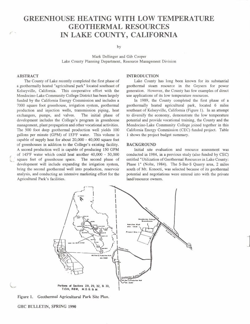
a geothermally heated "agricultural park" located southeast of Kelseyville, California. This cooperative effort with the Mendocino-Lake Community College District has been largely funded by the California Energy Commission and includes a 7000 square foot greenhouse, irrigation system, geothermal production and injection wells, transmission piping. heat exchangers, pumps, and valves. The initial phase of development includes the College's program in greenhouse management, plant propagation and other vocational activities. The 500 foot deep geothermal production well yields 100 gallons per minute (GPM) of 153"F water. This volume is capable of supply heat for about 20,000 - 40,000 square feet of greenhouses in addition to the College's existing facility. A second production well is capable of producing 150 GPM of 145"F water which could heat another 40,000 - 50,000
INTRODUCTION Lake County has long been known for its substantial
geotbennal steam resource in the Geysers for power generation. However, the County has few examples of direct use applications of its low temperature resources.
In 1989, tbe County completed the first phase of a geothermally heated agricultural park, located 6 miles southeast of Kelseyville, California (Figure I). In an attempt to diversify the economy, demonstrate the low temperature potential and provide vocational training, the County and the Mendocino-Lake Community College joined together in this California Energy Commission (CEC) funded project. Table I shows the project budget summary.
BACKGROUND
~ . square feet of greenhouse space. The second phase of
Initial site evaluation and resource assessment was conducted in 1984, in a previous study (also funded by CEC) entitled "Utilization of Geothermal Resources in Lake County:
development will include expanding the irrigation system, bring the second geothennal well into production, reservoir analysis, and conducting an intensive marketing effort for the Agricultural Park's facilities.
Figure I.
r--, , . -~
~ ~ \
'--. "'\
I
A5''''I',~_.,. --
Por16on1 d SKtioN 28, 29. ~2, 8. ll, TI~H, R8W, M.O.B. a w.
Geothermal Agricultural Park Site Plan.
GHC BULLETIN, SPRING 1990
I 1 1 I 1 1 1 I
. I -"'I \1 r
Phase I" (Nolte, 1984). The S-Bar-S Quarry area, 2 miles south of Mt. Konocti, was selected because of its geothermal potential and negotiations were entered into with the private land/resource owners.
.... uu
, ...... ,,,.
]
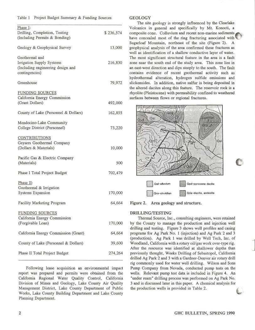
Table I Project Budget Summary & Funding Sources
Phase I: Drilling, Completion, Testing (Including Permits & Bonding)
Geology & Geophysical SUlVey
Geothermal and Irrigation Supply Systems (Including engineering design and contingencies)
Greenhouse
FUNDING SOURCES Cali fornia Energy Commission (Grant Dollars)
County of Lake (Personnel & Dollars)
Mendocino-Lake Community College District (Personnel)
CONTRIBUTIONS Geysers Geothermal Company (Dollars & Materials)
Pacific Gas & Electric Company (Materials)
Phase I Total Project Budget
Phase II: Geothermal & Irrigation Systems Expansion
Facility Marketing Program
FUNDING SOURCES California Energy Commission (Forgivable Loan)
California Energy Commission (Grant)
County of Lake (Personnel & Dollars)
Phase II Total Project Budget
$ 236,574
13,000
216,830
79,972
492,000
162,855
73,220
10,000
500
702,479
170,000
64,664
170,000
64,664
39,600
274,264
Following lease acqulsltion an environmental impact report was prepared and permits were obtained from the California Regional Water Quality Control, California Division of Mines and Geology, Lake County Air Quality Management District, Lake County Department of Public Works, Lake County Building Department and Lake County Planning Department.
2
GEOLOGY The site geology is strongly influenced by the Clearlake
Volcanics in general and specifically by Mt. Konocti, a com}X>site cone. Colluvium and recent non-marine sediments ""'." have concealed most of the ring fracturing associated with~.J
Sugarloaf Mountain, northeast of the site (Figure 2). A geophysical analysis of the area confirmed these fractures as well as identification of a shallow conductive layer of water. The most significant structural feature in the area is a fault wne near the south end of the study area. This wne lies in an east-west direction and dips steeply to the south. The fault contains evidence of recent geothermal activity such as hydrothermal alteration. hydrogen sulfide ernissions and slickensides. In addition. native sulfur is being deposited in the altered dacites along this feature. The reselVoir rock is a rhyolite (Pleistocene) with permeability confmed to weathered surfaces between flows or regional fractures.
III Qpd-pyroxene dacite
Iii ada-dacite, andesite
Figure 2. Area geology and structure.
DRILLINGrrESTING Thermal Source. Inc .• consulting engineers. were retained
by the County to manage the production and injection well drilling and testing. Figure 3 shows well profiles and casing programs for Ag Park No. I (injection) and Ag Park 2 and 3 (production). Ag Park I was drilled by Well Tech. Inc. of Woodland, California with a rotary oil/gas work over-type rig. After the resource was identified at shallower depths than previously thought. Weeks Drilling of Sebastopol, California drilled Ag Park 2 and 3 with a Gardner-Denver air rotary drill rig commonly used for water well drilling. Wilson and Sons Pump Company from Nevada. conducted pump tests on the wells. Relevant pump test data is included in Figure 4. An "under ream" drilling process was performed on Ag Park No. 3 and is discussed later in this paper. A chemical analysis for the production wells is provided in Table 2.
GHC BULLETIN, SPRING 1990
-I
]
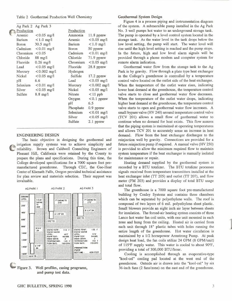
Table 2 Geothermal Production Well Chemistry
Ag Park 2 Ag Park 3 p Produ~tion Production
Arseruc <0.05 mg/l Ammonia 1l.8 ppmw Barium < 1.0 mg/l Arsenic <0.05 mg/l Boron 30.5 mgn Barium < 1.0 mg/l Cadmium <0.01 mg/l Boron 50 ppmw Chromium <0.05 Cadmium <0.01 mg/l Chloride 88 mg/l Chloride 71.9 ppmw Fluoride 0.26 mg/l Chromium <0.05 mg/l Lead <0.05 mg/l Fluoride 28.8 ppmw Mercury <0.002 mg/l Hydrogen Nickel <0.05 mg/l Sulfide 17.2 ppmw pH 6.6 Lead <0.05 mg/l Selenium <0.01 mg/l Mercury <0.002 mg/l Silver <0.05 mg/l Nickel <0.05 mg/l Sulfate 8.8 mg/l Nitrate < 11 ppb
Oxygen <0.1 ppmw pH 6.5 Phosphate 0.9 ppmw Selenium <0.01 mg/l Silver <0.05 mg/l Sulfate 2.1 ppmw
ENGINEERING DESIGN The basic objective in designing the geothermal and
n irrigation supply systems was to achieve simplicity and ~' reliability . Brown and Caldwell Consulting Engineers of
Pleasant Hill, California were retained by the County to prepare the plans and specifications. During this time, the College developed specifications for a 7000 square foot premanufactured greenhouse. Through CEC, the Geo-Heat Center of Klamath Falls, Oregon provided technical assistance for plan review and materials selection. Their support was invaluable.
AG PARK I AG PARK 2 AGPARK 3
.... :600'
.... , ....
c · ... "*" Figure 3. Well profiles, casing programs, and pump test data.
GHC BULLETIN, SPRING 1990
H4'
B."" ,. lS1 f
15S(;PM
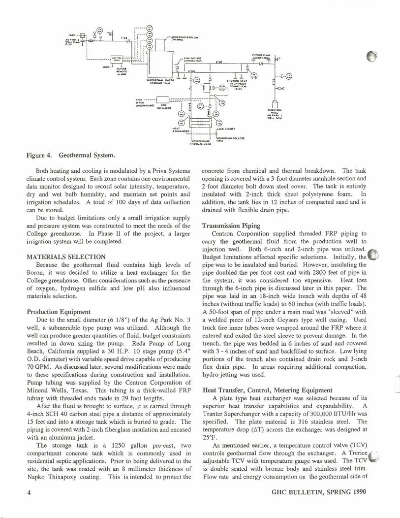
Geothennal System Design Figure 4 is a process piping and instrumentation diagram
of the system. A submersible pump installed in the Ag Park No.3 well pumps hot water to an underground storage tank. The pump is operated by a level control system located in the storage tank. As the water level in the tank drops below the low level setting, the pump will start. The water level will rise until the high level setting is reached and the pump stops. In the future, high and low level alarm signals will be provided through a phone modem and computer system for remote alarm indication.
Geothermal water flow from the storage tank to the Ag Park is by gravity. Flow through a plate type heat exchanger in the College's greenhouse is controlled by a temperature control valve located on the outlet side of the heat exchanger. When the temperature of the outlet water rises, indicating lower heat demand at the greenhouse, the temperature control valve starts to close and geothermal water flow decreases. When the temperature of the outlet water drops, indicating higher heat demand at the greenhouse, the temperature control valve starts to open and geothermal water flow increases. A small bypass valve (HV 240) around temperature control valve (TCV 201) allows a small flow of geothermal water to continue when no demand for heat exists. This flow assures that the piping system is maintained at operating temperatures and allows TCV 201 to accurately sense an increase in heat demand. Flow from the heat exchanger discharges to the reinjection well by gravity. Connections are provided for a future reinjection pump if required. A manual valve (HV 250) is provided to allow the minimum required flow to maintain system temperature if the heat exchanger is manually isolated for maintenance or repair.
Heating demand supplied by the geothermal system is recorded by a BTU totalizer. The BTU totalizer processes signals received from temperature transmitters installed at the heat exchanger inlet (TT 205) and outlet (IT 207), and flow meter (FM 203) and provides a display of total BTU usage and total flow.
The greenhouse is a 7000 square foot pre-manufactured building by Conley Systems and contains three chambers which can be separated by polyethylene walls. The roof is composed of two layers of 6 mil. polyethylene sheet plastic. Small blowers provide an eight inch air layer between sheets for insulation. The forced-air heating system consists of three Lanco hot water fan coil units, with one unit mounted in each zone and hung from the ceiling. Heated air is carried from each unit through 18" plastic tubes with holes running the entire length of the greenhouse. Hot water circulation is maintained by a 112 horsepower Armstrong Pump. At peak design heat load, the fan coils utilize 24 GPM (8 GPM/unit) of 115'F supply water. This water is cooled to about 90'F, providing a total of 300,000 BTU/hour.
Cooling is accomplished through an evaporative-type "kool-cel' cooling pad located at the west end of the greenhouse. Outside air is drawn into the "kool-ce1" by six 36-inch fans (2 fans/wne) on the east end of the greenhouse.
3
1
_CTIQOI
~" "Q,..- •
~~,g~(.l. ~ .. ~~~gr-[·~l"'l co.ooo,y
..oocooQ ""UQOI ".U...ouat 1_.
""l Ill'
ltC ....... lOAQ
Figure 4. Geothennal System.
Both heating and cooling is modulated by a Priva Systems climate control system. Each zone contains one environmental data monitor designed to record solar intensity, temperature, dry and wet bulb humidity, and maintain set points and irrigation schedules. A total of 100 days of data collection can be stored.
Due to budget limitations only a small irrigation supply and pressure system was constructed to meet the needs of the College greenhouse. In Phase II of the project, a larger irrigation system will be completed.
MATERIALS SELECTION Because the geothermal fluid contains high levels of
Boron, it was decided to utilize a heat exchanger for the College greenhouse. Other considerations such as the presence of oxygen, hydrogen sulfide and low pH also influenced materials selection.
Production Equipment Due to the small diameter (6 li8") of the Ag Park No.3
well, a submersible type pump was utilized. Although the well can produce greater quantities of fluid, budget constraints resulted in down sizing the pump. Reda Pump of Long Beach, California supplied a 30 H.P. 10 stage pump (5.4" 0.0. diameter) with variable speed drive capable of producing 70 GPM. As discussed later, several modifications were made to these specifications during construction and installation. Pump tubing was supplied by the Centron Corporation of Mineral Wells, Texas. This tubing is a thick-walled FRP tubing with threaded ends made in 29 foot lengths.
After the fluid is brought to surface, it is carried through 4-inch SCH 40 carbon steel pipe a distance of approximately 15 feet and into a storage tank which is buried to grade. The piping is covered with 2-inch fiberglass insulation and encased with an aluminum jacket.
The storage tank is a 1250 gallon pre-cast, two compartment concrete tank which is commonly used in residential septic applications. Prior to being delivered to the site, the tank was coated with an 8 millimeter thickness of Napko Thixapoxy coating. This is intended to protect the
4
concrete from chemical and thermal breakdown. The tank opening is covered with a 3-foot diameter manhole section and 2-foot diameter bolt down steel cover. The tank is entirely insulated with 2-inch thick sheet polystyrene foam. In addition, the tank lies in 12 inches of compacted sand and is drained with flexible drain pipe.
Transmission Piping Centron Corporation supplied threaded FRP plplllg to
carry the geothermal fluid from the production well to injection well. Both 6-inch and 2-inch pipe was utilized. A Budget limitations affected specific selections. Initially, the"-' pipe was to be insulated and buried. However. insulating the pipe doubled the per foot cost and with 2800 feet of pipe in the system, it was considered too expensive. Heat loss through the 6-inch pipe is discussed later in this paper. The pipe was laid in an 18-inch wide trench with depths of 48 inches (without traffic loads) to 60 inches (with traffic loads). A 50-foot span of pipe under a main road was "sleeved" with a welded piece of 12-inch Geysers type well casing. Used truck tire inner tubes were wrapped around the FRP where it entered and exited the steel sleeve to prevent damage. In the trench, the pipe was bedded in 6 inches of sand and covered with 3 - 4 inches of sand and backfilled to surface. Low lying portions of the trench also contained drain rock and 3-inch flex drain pipe. In areas requiring additional compaction, hydro-jetting was used.
Heat Transfer, Control, Metering Equipment A plate type heat exchanger was selected because of its
superior heat transfer capabilities and expandability. A Tranter Superchanger with a capacity of 300,000 BTu/Hr was specified. The plate material is 316 stainless steel. The temperature drop (t> T) across the exchanger was designed at 25'F.
As mentioned earlier, a temperature control valve (TCY) controls geothermal flow through the ~xchanger. A Trerice I adjustable TCY with temperature gauge was used. The TCY~ is double seated with bronze body and stainless steel trim. Flow rate and energy consumption on the geothermal side of
GHC BULLETIN, SPRING 1990
]
the exchanger are monitored by a Hersey model 7003 BTU measurement system. Temperature sensors, 50 GPM turbine flow meter and a control/display instrument are included. The display unit shows instantaneous flow rate, temperature difference and BTUIhr. In addition,S digit BTU and gallons totalizers are provided.
Disposal Equipment After heat is extracted geothermal fluid continues to flow
by gravity to the injection well. Blind flanges are located along this portion of piping for future connections. Pipe rises above ground and is the same SCH 40 carbon steel pipe with insulation as at the production well. The injection well is capable of accepting approximately 400 GPM by gravity, but currently the maximum is 70 GPM. Injection pressure (gravity head) is approximately 50 - 60 PSI.
Greenhouse Distribution System Service loop piping for greenhouse fan coil units is high
temperature SCH 40 CPVC in sizes from 2 inch down to 3/4 inch diameter. A 5 gallon pressure tank and 112 h.p. Armstrong pump and motor pressurize the supply system. Supply and return temperature and pressure gauges are also provided.
CONSTRUCTION Greenhouse
Mendocino College originally planned to have the greenhouse supplied and constructed by one contractor. e However, all bids received were much higher than budgeted. Innovative solutions were required to make this portion of the project a reality. The College hired a construction manager with greenhouse experience to oversee purchase of materials and construction. A service contract was signed with Konocti Industries of Lakeport, California, a nonprofit organization employing developmentally disabled residents, to build the greenhouse. This arrangement allowed construction to be completed within the limited budget and time schedule.
Geothennal System While the College was building the greenhouse, the
County went to bid for construction of the geothermal system. Only one bid was received and a contract was negotiated with Richelieu-Wemer Construction Services of Redding, California. The project was originally designed to have two production wells connected to the system along with a large irrigation system which included a 21,000 gallon storage tank and pressure booster package. As mentioned earlier, the budget limited the existing system to a small irrigation system and connection of only one production well to the system. Table 3 shows construction costs for various system components.
The first stage of construction included installation of the geothermal piping. The contract was signed in October 1988,
.. and the pipe was on site within 6 weeks. The mechanical C subcontractor installed approximately 2600 feet of pipe within
8 working days. This was completed by two laborers and I
GHC BULLETIN, SPRING 1990
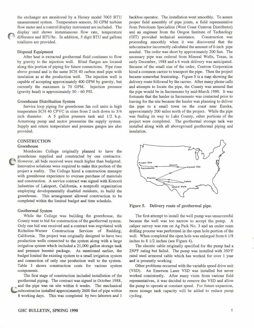
backhoe operator. The installation went smoothly. To assure proper field assembly of pipe joints, a field representative from Petroleum Specialties (West Coast Centron Distributor) and an engineer from the Oregon Institute of Technology (OlD provided technical assistance. Construction was proceeding smoothly when it was discovered that the subcontractor incorrectly calculated the amount of 6-inch pipe needed. The order was short by approximately 200 feet. The necessary pipe was ordered from Mineral Wells, Texas, in early December, 1988 and a 6 week delivery was anticipated. Because of the small size of the order, Centron Corporation hired a common carrier to transport the pipe. Then the project became somewhat frustrating. Figure 5 is a map showing the delivery route followed by the carrier. After many phone calls and attempts to locate the pipe, the County was assured that the pipe would be in Sacramento by mid-March 1989. It was fortunate that the hauler in Sacramento was contacted prior to leaving for the site because the hauler was planning to deliver the pipe to a small town on the coast near Eureka, approximately 200 miles north of the project. While the pipe was finding its way to Lake County, other portions of the project were completed. The geothermal storage tank was installed along with all aboveground geothermal piping and insulation.
Figure 5. Delivery route of geothennal pipe.
The first attempt to install the well pump was unsuccessful because the well was too narrow to accept the pump. A caliper survey was run on Ag Park No. 3 and an under ream drilling process was performed in the open hole portion of the well. When completed the open hole was enlarged from 6 1/8 inches to 8 112 inches (see Figure 4).
The electric cable originally specified for the pump had a 25O"F rating but failed. The pump was installed with 350"F rated steel armored cable which bas worked for over 1 year and is presently working.
Other problems occurred with the variable speed drive unit (VSD). An Emerson Laser VSD was installed but never worked consistently. After many visits from various field representatives, it was decided to remove the VSD and allow the pump to operate at constant speed. For future expansion. more storage tank capacity will be added to reduce pump cycling.
5
]
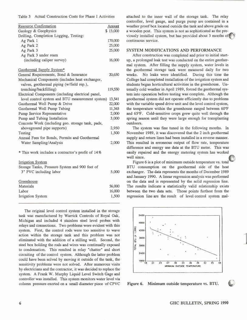
Table 3 Actual Construction Costs for Phase I Activities
Resource Confirmation Geology & Geophysics Drilling, Completion Logging, Testing:
Ag Park I Ag Park 2 Ag Park 3 Ag Park 3 under ream
(including caliper survey)
Geothermal Supply System* General Requirements, Bond & Insurance Mechanical Components (includes heat exchanger,
valves, geothermal piping (w/field rep.), trenchinglbackfilling)
Electrical Components (including electrical panel,
Annn $ 13,(0)
170,<XXl 25,(0) 25,(0)
16,(0)
2lJ,650
119,550
level control system and BTU measurement system) Geothermal Well Pump & Drive
13,541 22,(0) 11,345 2,(0) 3,(0)
Geothermal Well I'Ilmp Tubing Pump Service Representative Pump and Tubing Installation Concrete Work (including geo. storage tank, pads,
aboveground pipe supports) Testing Annual Fees for Bonds, Permits and Geothermal
Water Sampling/Analysis
* This work includes a contractor's profit of 14%
Irrigation System Storage Tanks, Pressure System and 900 feet of
3" PVC including labor
Greenhouse Materials Labor Irrigation System
2,950 1,500
2,(0)
5,(0)
56,(0) 16,(0) 1,500
The original level control system installed in the storage tank was manufactured by Warrick Controls of Royal Oak, Michigan and included 4 stainless steel level probes with relays and connections. Two problems were evident with this system. First, the control rods were too sensitive to wave action within the storage tank and this problem was not eliminated with the addition of a stilling well. Second, the steel box holding the rods and wires was continually exposed to condensation. This resulted in relay "chatter" and short circuiting of the control system. Although the latter problem could have been solved by moving it outside of the tank, the sensitivity problems were not solved. After numerous visits by electricians and the contractor, it was decided to replace the system. A Frank W. Murphy Liquid Level Switch Gage and controller was installed. This system monitors water level via column pressure exerted on a small diameter piece of CPVC
6
attached to the inner wall of the storage tank. The relay controller, level gauge, and purge pump are contained in a weather proof box located outside the tank and above grade on a wooden post. This system is not as sophisticated as the previously installed system, but has provided about 3 months ofO' contmuous service.
SYSTEM MODIFICATIONS AND PERFORMANCE After construction was completed and prior to initial start
up, a prolonged leak test was conducted on the entire geothermal system. After filling the supply system, water levels in the geothermal storage tank were measured daily for two weeks. No leaks were identified. During this time the COllege had completed installation of the irrigation system and students began horticultural activities in the greenhouse. Unusually cold weather in April 1989, forced the geothermal system into operation before testing was complete. Although the geothermal system did not operate efficient! y due to problems with the variable speed drive unit and the level control system, the temperature within the greenhouse ranged between 6O"F and 65°F. Cold-sensitive crops grew quite well through the spring season until they were large enough for transplanting outdoors.
The system was fine tuned in the following months. In November 1989, it was discovered that the 2 inch geothermal supply and return lines had been installed in a reverse manner. This resulted in erroneous output of flow rate, temperature difference and energy use data at the BTU meter. This was easily repaired and the energy metering system has worked well since. C
Figure 6 is a plot of minimum outside temperature vs. total . BTU consumption on the geothermal side of the heat exchanger. The data represents the months of December 1989 and January 1990. A linear regression analysis was performed on the data and is represented by the solid regression line. The results indicate a statistically valid relationship exists between the two data sets. Those points furthest from the regression line are the result of level control system mal-
''''0 .... -~ '200
:
'" : ~
J6O()
~ JOOO
"00
I~
" 21 " 27 '" "
,. " ., ., ..
""""""'" OUTSIOC l'[Mf>[RATUft(
Figure 6. Minimwn outside temperature vs. BTU.
GHC BULLETIN, SPRING 1990
]
functions and/or electrical power failures. The supply system then requires several hours to fill the pipeline and come into thenna! equilibrium. For December 1989, approximately 104.9 million BTU were consumed to meet a
("·set point of 65°F. In January 1990, 115.2 million BTU were consumed to meet the same set point conditions.
.90
,eo
17. ........... .,
~ 16.
.'" , , ~ 14.
"" : ,
12" 11. •• 21 ,.
" 30 JJ ,. J. " ., .. ............. J(IrIPERATlJF«:
Figure 7. Minimum outside temperature vs. BTU/gal.
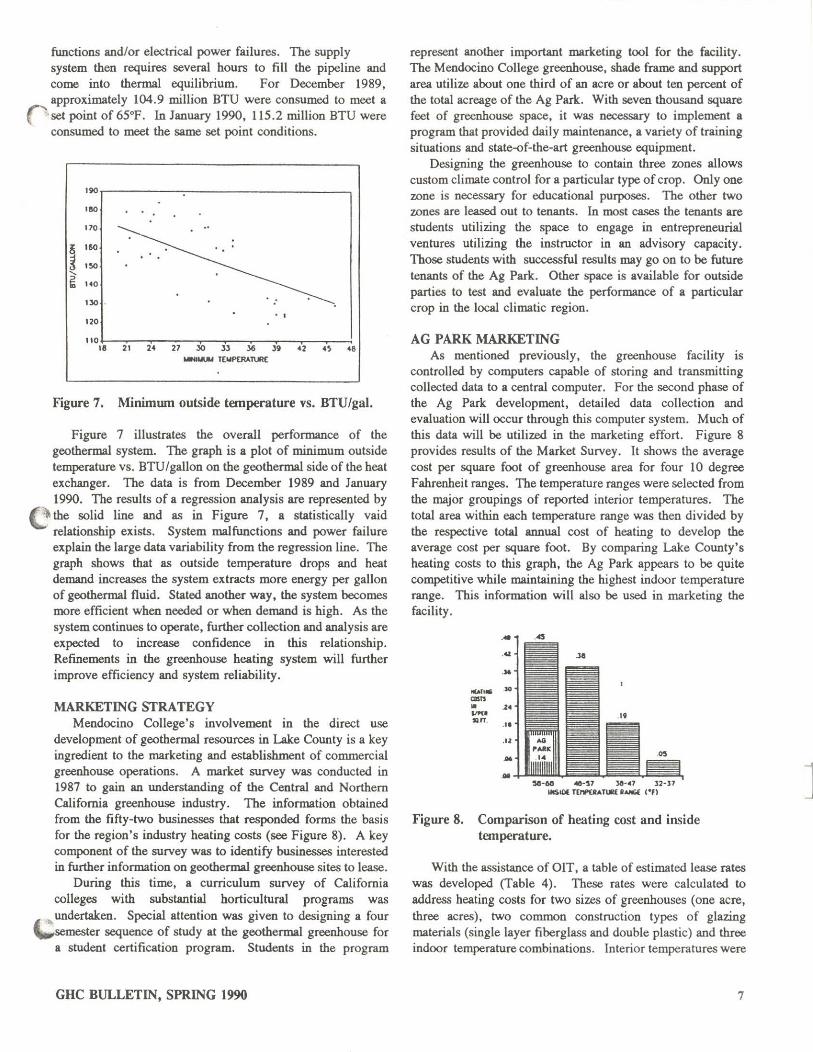
Figure 7 illustrates the overall performance of the geothermal system. The graph is a plot of minimum outside temperature vs. BTU/gallon on the geothenna! side of the heat exchanger. The data is from December 1989 and January 1990. The results of a regression analysis are represented by
C the solid line and as in Figure 7, a statistically vaid relationship exists. System malfunctions and power failure explain the large data variability from the regression line. The graph shows that as outside temperature drops and heat demand increases the system extracts more energy per gallon of geothenna! fluid. Stated another way, the system becomes more efficient when needed or when demand is high. As the system continues to operate, further collection and analysis are expected to increase confidence in this relationship. Refinements in the greenhouse heating system will further improve efficiency and system reliability.
MARKETING SfRA TEGY Mendocino College's involvement in the direct use
development of geothenna! resources in Lake County is a key ingredient to the marketing and establishment of commercial greenhouse operations. A market survey was conducted in 1987 to gain an understanding of the Central and Northern Califorrua greenhouse industry. The information obtained from the fifty-two businesses that responded foffiJS the basis for the region'S industry heating costs (see Figure 8). A key component of the survey was to identify businesses interested in further information on geothenna! greenhouse sites to lease.
During this time, a curriculum survey of California colleges with substantial horticultural programs was
• ~ undertaken. Special attention was given to designing a four -.-semester sequence of study at the geothermal greenhouse for
a student certification program. Students in the program
GHC BULLETIN, SPRING 1990
represent another important marketing tool for the facility. The Mendocino College greenhouse, shade frame and support area utilize about one third of an acre or about ten percent of the total acreage of the Ag Park. With seven thousand square feet of greenhouse space, it was necessary to implement a program that provided daily maintenance, a variety of training situations and state-of-the-art greenhouse equipment.
Designing the greenhouse to contain three zones allows custom climate control for a particular type of crop. Onlyone zone is necessary for educational purposes. The other two zones are leased out to tenants . In most cases the tenants are students utilizing the space to engage in entrepreneurial ventures utilizing the instructor in an advisory capacity. Those students with successful results may go on to be future tenants of the Ag Park. Other space is available for outside parties to test and evaluate the performance of a particular crop in the local climatic region.
AG PARK MARKETING As mentioned previously. the greenhouse facility is
controlled by computers capable of storing and transmitting collected data to a central computer. For the second phase of the Ag Park development, detailed data collection and evaluation will occur through this computer system. Much of this data will be utilized in the marketing effort. Figure 8 provides results of the Market Survey. It shows the average cost per square foot of greenhouse area for four 10 degree Fahrenheit ranges. The temperature ranges were selected from the major groupings of reported interior temperatures. The total area within each temperature range was then divided by the respective total annual cost of heating to develop the average cost per square foot. By comparing Lake County's heating costs to this graph, the Ag Park appears to be quite competitive while maintaining the highest indoor temperature range. This information will also be used in marketing the facility.
...., .. """ • "". son
50~60 .a-'1 )0-"1 12-n ~lO( TEI'V"UATW RAIIGf: ,en
Figure 8. Comparison of heating cost and inside temperature.
With the assistance of OIT, a table of estimated lease rates was developed (Table 4). These rates were calculated to address heating costs for two sizes of greenhouses (one acre, three acres), two common construction types of glazing materials (single layer fiberglass and double plastic) and three indoor temperature combinations. Interior temperatures were
7
]
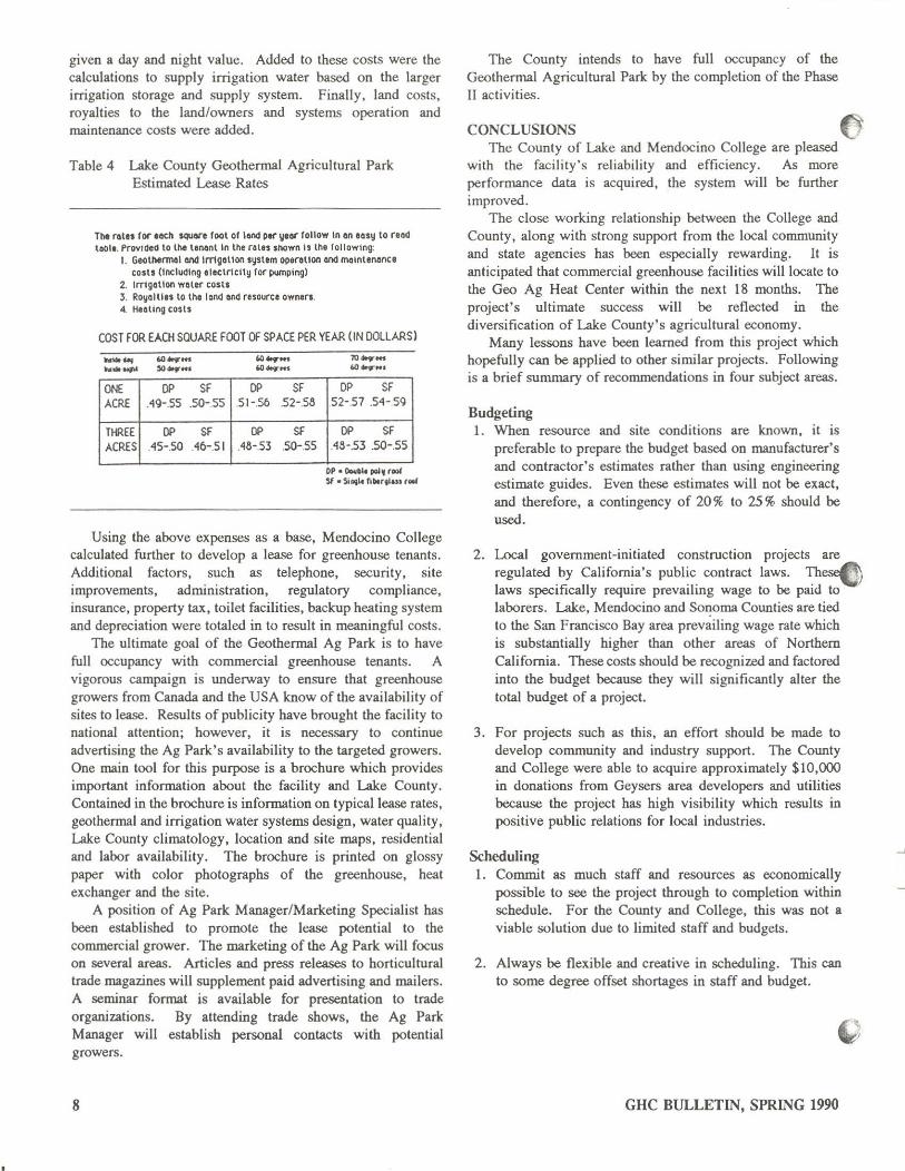
given a day and night value. Added to these costs were the calculations to supply irrigation water based on the larger irrigation storage and supply system. Finally , land costs, royalties to the land/owners and systems operation and maintenance costs were added.
Table 4 Lake County Geothermal Agricultural Park Estimated Lease Rates
Tht roln for eech SQUMt fool of IQI'Id per ~or follow In on ICity to reod loot • . Provided to 11'11 tenonlln the ral.,shown is the follOWIng:
I. G,othtrmol Md ImgGtlon systtm opecouon end mainlerltlnce costs (inclUding electricity for pumping)
2. Irrlgatioo WOler costs 3. l1:oyaltilS to the lond and ruource owners. 4. Heating costs
COST fOR EACH SOUARE fOOT Of SPACE PER YEAR (IN DOLLARS)
ONE DP Sf DP ACRE .49-.5S 50-5S 5t-56
THREE DP Sf DP ACRES A5-.50 A6-5 I A8-53
Sf 52-5a
Sf .SO-55
DP Sf S2-57 54-59
DP Sf .48-.53 .SO-.55
OP • DIMI ... pol, (101 Sf. Silllil. fiMrtl.u ,Ottl
Using the above expenses as a base, Mendocino College calculated further to develop a lease for greenhouse tenants. Additional factors, such as telephone, security, site improvements, administration, regulatory compliance. insurance, property tax, toilet facilities, backup heating system and depreciation were totaled in to result in meaningful costs.
The ultimate goal of the Geothermal Ag Park is to have full occupancy with commercial greenhouse tenants. A vigorous campaign is underway to ensure that greenhouse growers from Canada and the USA know of the availability of sites to lease. Results of publicity have brought the facility to national attention; however, it is necessary to continue advertising the Ag Park's availability to the targeted growers. One main tool for this purpose is a brochure which provides important information about the facility and Lake County. Contained in the brochure is information on typical lease rates, geothermal and irrigation water systems design, water quality, Lake County climatology, location and site maps, residential and labor availability. The brochure is printed on glossy paper with color photographs of the greenhouse, heat exchanger and the site.
A position of Ag Park ManagerlMarketing Specialist has been established to promote the lease potential to the commercial grower. The marketing of the Ag Park will focus on several areas. Articles and press releases to horticultural trade magazines will supplement paid advertising and mailers. A seminar format is available for presentation to trade organizations. By attending trade shows, the Ag Park Manager will establish personal contacts with potential growers.
8
The County intends to have full occupancy of the Geothermal Agricultural Park by the completion of the Phase II activities.
CONCLUSIONS (1 The County of Lake and Mendocino College are pleased
with the facility's reliability and efficiency. As more performance data is acquired, the system will be further improved.
The close working relationship between the College and County, along with strong support from the local community and state agencies has been especially rewarding. It is anticipated that commercial greenhouse facilities will locate to the Geo Ag Heat Center within the next 18 months. The project's ultimate success will be reflected in the diversification of Lake County's agricultural economy.
Many lessons have been learned from this project which hopefully can be applied to other similar projects. Following is a brief summary of recommendations in four subject areas.
Budgeting 1. When resource and site conditions are known, it is
preferable to prepare the budget based on manufacturer's and contractor's estimates rather than using engineering estimate guides. Even these estimates will not be exact, and therefore, a contingency of 20 % to 25 % should be used.
2. Local government-initiated construction projects are regulated by California's public contract laws. TheseC laws specifically require prevailing wage to be paid to laborers. Lake, Mendocino and Sot:oma Counties are tied to the San Francisco Bay area prevailing wage rate which is substantially higher than other areas of Northern California. These costs should be recognized and factored into the budget because they will significantly alter the total budget of a project.
3. For projects such as this, an effort should be made to develop community and industry support. The County and College were able to acquire approximately $lO,OOO in donations from Geysers area developers and utilities because the project has high visibility which results in positive public relations for local industries.
Scheduling 1. Commit as much staff and resources as economically
possible to see the project through to completion within schedule. For the County and College, this was not a viable solution due to limited staff and budgets.
2. Always be flexible and creative in scheduling. This can to some degree offset shortages in staff and budget.
GHC BULLETIN, SPRING 1990
]
Drilling 1. Use a geophysical analysis to support existing geological,
geochemical and related data. In areas where the geothermal resource is believed to be shallow « 800 feet) , an electrical resistivity survey (i.e., PseudoSchlumberger) may be useful.
2. When constructing geothermal wells, allow for a diameter which can easily accommodate the anticipated production well pump. However, remember that the cost of drilling a well increases dramatically as diameter increases.
3. Conduct a caliper survey after completing and testing each well. This data is useful for future pump installation and production formation lithology.
4. Use geologists and drillers with knowledge of local geologic and hydrologic conditions.
Construction I. Be sure to have sound engineering plans and specifications
prepared because the project will be no better than these plans. Utilize competent engineering firms with specific experience in geothermal applications, well pumps, heat transfer, and corrosion/scaling engineering.
2. When available, utilize specialized consultants such as the California Energy Commissions' Technical Assistance subcontractors from OIT. This provides the necessary quality control during design and construction. In addition, valuable infonnation on materials selection and types of problematic components can be acquired from these experts.
3. Where possible, simplicity of the system design should be a major consideration when preparing plans and specifications. In this context simplicity is defined as systems or components: I) with fewer moving parts; 2) that can be repaired or replaced locally and quickly, and 3) which have field representatives located near the project. This will allow for easier operation and maintenance by technical people who may not be familiar with the system.
4. Staff should be on site during all phases of construction to insure proper installation and quality control. When materials are lost during shipment, time must be committed to tracking the location and delivery schedule of materials.
5. When projects lend themselves to a phased development approach, the design should be equally flexible to allow for phasing. For example, the Geothermal Agricultural Heat Center is ultimately designed to have two production wells, and a much larger irrigation system. One well has been brought into production earlier and a small irrigation "module" installed to supply the greenhouse. This phasing allows for the system expansion at a later date.
GHC BULLETIN, SPRING 1990
ACKNOWLEDGEMENTS Numerous individuals and organizations contributed to
this project. The authors wish to thank Alex Hinds (Lake County) and Terry Parker (Mendocino College) who wrote the original grant, the various agencies, especially Mike Smith of California Energy Commission, Lake County Board of Supervisors, Mendocino College Board of Trustees, Ruth Lincoln (Lake County Center of Mendocino-Lake Community College), Oregon Institute of Technology (Goo-Heat Center), Chuck Werner (Richelieu-Werner Construction), Dick Dunlap (Therma Source, Inc.) and Bob Reynolds (Lake County Air Quality Management District). Many people assisted in the preparation of this paper. Dinah Sullivan and Cindy Phillips of the Lake County Planning Department diligently prepared the text. Steve Zalusky of the Lake County Planning Department conducted the statistical analysis. Lon Sharp of the Lake County Planning Department produced the graphic illustrations. In addition, Alex Hinds of the Lake County Planning Department, and Kevin Rafferty and Gene Culver of orr reviewed the paper.
REFERENCES 1. Brown and Caldwell Engineers, 1988, "Agricultural Park
Geothermal Project Plans and Specifications," W. Fleming and J. Bartlett, principal engineers.
2. Cooper, Gib, 1987, "Greenhouse Growers Market Survey Report," funded through the Phase I Grant from the California Energy Commission.
3. Dunlap, Richard, 1990, oral communication.
4. Hearn, B., Julie Donnelly-Nolan and Fraser Goff, 1981, "The Clear Lake Volcanics: Tectonic Setting and Magma Sources, " in Research in the Geysers-Clear Lake Geothermal Area. Northern California, U.S. Geological Survey Professional Paper 1141, pp. 25-45.
5. McNitt, James R., 1968, "Geology of the Kelseyville Quadrangle, Sonoma, Lake and Mendocino Counties, California," Map Sheet No.9, California Division of Mines and Geology.
6. Nolte, George S., et aI., 1984, "Development and Utilization of Geothermal Resources in Lake County, California," funded through a grant from the California Energy Commission.
7. Thompson, J. Michael, 1984, "The Konocti Bay Fault rone, Lake County, California: ARe-Evaluation," in Geothermal Resources Council Transactions, Vol. 8, pp. 383-389, Davis, California.
9
J