GRAVITY Template Manual · This manual is valid for observations with GRAVITY during ESO Period...
23
EUROPEAN SOUTHERN OBSERVATORY Organisation Europ´ eene pour des Recherches Astronomiques dans l’H´ emisph` ere Austral Europ¨ aische Organisation f¨ ur astronomische Forschung in der s¨ udlichen Hemisph¨ are ESO - European Southern Observatory Karl-Schwarzschild Str. 2, D-85748 Garching bei M¨ unchen Very Large Telescope Paranal Science Operations GRAVITY Template Manual Doc. No. VLT-MAN-ESO-15830-3523 Issue 100, Date 2017-08-01 Gravity consortium & IOT 2017-08-01 Prepared .......................................... Date Signature S. Mieske Approved .......................................... Date Signature A. Kaufer Released .......................................... Date Signature
-
Upload
nguyennguyet -
Category
Documents
-
view
214 -
download
0
Transcript of GRAVITY Template Manual · This manual is valid for observations with GRAVITY during ESO Period...

EUROPEAN SOUTHERN OBSERVATORY
Organisation Europeene pour des Recherches Astronomiques dans l’Hemisphere AustralEuropaische Organisation fur astronomische Forschung in der sudlichen Hemisphare
ESO - European Southern ObservatoryKarl-Schwarzschild Str. 2, D-85748 Garching bei Munchen
Very Large Telescope
Paranal Science Operations
GRAVITY Template Manual
Doc. No. VLT-MAN-ESO-15830-3523
Issue 100, Date 2017-08-01
Gravity consortium & IOT 2017-08-01Prepared . . . . . . . . . . . . . . . . . . . . . . . . . . . . . . . . . . . . . . . . . .
Date Signature
S. MieskeApproved . . . . . . . . . . . . . . . . . . . . . . . . . . . . . . . . . . . . . . . . . .
Date Signature
A. KauferReleased . . . . . . . . . . . . . . . . . . . . . . . . . . . . . . . . . . . . . . . . . .
Date Signature

GRAVITY Template Manual VLT-MAN-ESO-15830-3523 ii
This page was intentionally left blank

GRAVITY Template Manual VLT-MAN-ESO-15830-3523 iii
Change Record
Issue/Rev. Date Section/Parag. affected Remarks
98 30/04/16 Document created99 01/12/16 all Acquisition template split for SF and DF
99.1 31/01/17 Tables 1 and 2100 12/07/17 all Complete revision of the document
100.1 01/08/17 all Correction of typos and outdated information

GRAVITY Template Manual VLT-MAN-ESO-15830-3523 iv
This page was intentionally left blank

GRAVITY Template Manual VLT-MAN-ESO-15830-3523 v
Contents
1 INTRODUCTION 1
1.1 Scope . . . . . . . . . . . . . . . . . . . . . . . . . . . . . . . . . . . . . . . . 1
1.2 Contact information . . . . . . . . . . . . . . . . . . . . . . . . . . . . . . . . 1
1.3 Period of validity of this manual . . . . . . . . . . . . . . . . . . . . . . . . . . 1
1.4 Glossary . . . . . . . . . . . . . . . . . . . . . . . . . . . . . . . . . . . . . . . 1
1.5 Modifications for P100 . . . . . . . . . . . . . . . . . . . . . . . . . . . . . . . 3
2 GRAVITY TEMPLATES 3
2.1 Observing modes . . . . . . . . . . . . . . . . . . . . . . . . . . . . . . . . . . 3
2.2 The acquisition template . . . . . . . . . . . . . . . . . . . . . . . . . . . . . . 4
2.2.1 Which star is which in single-field mode? . . . . . . . . . . . . . . . . . 5
2.2.2 Which star is which in dual-field mode? . . . . . . . . . . . . . . . . . . 5
2.2.3 Proper motion and parallax . . . . . . . . . . . . . . . . . . . . . . . . 5
2.2.4 MACAO guiding with the UTs . . . . . . . . . . . . . . . . . . . . . . 5
2.2.5 STRAP guiding with the ATs . . . . . . . . . . . . . . . . . . . . . . . 6
2.2.6 Science and fringe-tracking K magnitudes . . . . . . . . . . . . . . . . 6
2.2.7 Field guiding H-band magnitude . . . . . . . . . . . . . . . . . . . . . 7
2.2.8 Selecting the polarisation mode . . . . . . . . . . . . . . . . . . . . . . 7
2.2.9 Selecting the resolution mode . . . . . . . . . . . . . . . . . . . . . . . 7
2.2.10 Fringe-tracker . . . . . . . . . . . . . . . . . . . . . . . . . . . . . . . . 7
2.2.11 Dual-field mode . . . . . . . . . . . . . . . . . . . . . . . . . . . . . . . 8
2.3 The observation template . . . . . . . . . . . . . . . . . . . . . . . . . . . . . 9
2.3.1 Integration time . . . . . . . . . . . . . . . . . . . . . . . . . . . . . . . 9
2.3.2 Execution time . . . . . . . . . . . . . . . . . . . . . . . . . . . . . . . 11
2.3.3 Acquisition camera frames . . . . . . . . . . . . . . . . . . . . . . . . . 11
3 TEMPLATE KEYWORDS 13
3.1 Acquisition templates . . . . . . . . . . . . . . . . . . . . . . . . . . . . . . . . 13
3.1.1 GRAVITY dual acq.tsf . . . . . . . . . . . . . . . . . . . . . . . . . . . 13
3.1.2 GRAVITY single acq.tsf . . . . . . . . . . . . . . . . . . . . . . . . . . 14
3.1.3 Acquisition keywords . . . . . . . . . . . . . . . . . . . . . . . . . . . . 14
3.2 Observing templates . . . . . . . . . . . . . . . . . . . . . . . . . . . . . . . . 16
3.2.1 GRAVITY dual obs exp.tsf . . . . . . . . . . . . . . . . . . . . . . . . 16
3.2.2 GRAVITY dual obs calibrator.tsf and GRAVITY single obs *.tsf . . . 16
3.2.3 Observing keywords . . . . . . . . . . . . . . . . . . . . . . . . . . . . . 16

GRAVITY Template Manual VLT-MAN-ESO-15830-3523 1
1 INTRODUCTION
1.1 Scope
This document describes the observing templates for the 2nd generation VLTI instrumentGRAVITY. This document should be used for preparing GRAVITY observations startingwith period P100. Like with other VLT instruments, observations with GRAVITY are carriedout making use of observation blocks (OBs). The OBs must be created by the user duringPhase 2 preparation with the P2PP tool or the p2 application on the web. An OB is a setof observing templates that describe and detail the target acquisition and the data recording.The user has to define the values of the template keywords (parameters).
The Template Manual requires the user to have some basic understanding of the GRAVITYinstrument. If you are a first time user, we recommend to read the GRAVITY User Manualfor P100, which can be found at:
http://www.eso.org/sci/facilities/paranal/instruments/gravity/doc
The OBs are prepared with the P2PP tool. Installation instructions and documentationfor this tool can be found at: http://www.eso.org/observing/p2pp. GRAVITY specifictemplates will be downloaded by the P2PP tool itself. If help is needed, we kindly point thereader towards the step by step tutorial for using P2PP with the GRAVITY templates.
Starting with period P99, ESO has implemented the new web application p2 in support of thepreparation of Phase 2 material. The web interface is available at: http://www.eso.org/p2.Visitors at Paranal are asked to prepare their observations with this web-based application.OBs created or changed through p2 will be directly recorded in ESO’s database and directlybecome available at the telescope on Paranal. It is foreseen that in the near future also servicemode OBs will have to be prepared using the p2 web application. Furthermore it is plannedthat ASPRO1 provides direct access to ESO’s database. This will allow to prepare OBs anddirectly send them to ESO using this tool.
Finally, the VLTI manual needs to be consulted for a description of those parts of the interfer-ometer which are not instrument specific (e.g. AT configurations, limited magnitudes for fieldguiding, etc.) that one needs for preparing VLTI observations: link to VLTI User Manual
1.2 Contact information
In case of questions or suggestions related to Phase-2 preparation, please contact the ESOUser Support Department ([email protected]).
1.3 Period of validity of this manual
This manual is valid for observations with GRAVITY during ESO Period 100, starting October1st, 2017 and ending March 31st, 2018.
1.4 Glossary
• Constraint Set (CS)List of requirements for the conditions of the observation that is given inside an OB.
1See http://www.jmmc.fr/aspro.

GRAVITY Template Manual VLT-MAN-ESO-15830-3523 2
OBs are only executed under this set of minimum conditions.
• Observation Block (OB)An Observation Block is the smallest schedulable entity for the VLT. It consists of asequence of Templates. Usually, one Observation Block includes one target acquisitionand up to three exposure templates.
• Observation Description (OD)A sequence of templates used to specify the observing sequences within one or moreOBs.
• Observation Toolkit (OT)A tool used to create queues of OBs for scheduling and possible execution in servicemode taking the constraint set (CS) into account.
• Proposal Preparation and Submission (Phase 1)The Phase 1 begins right after the CfP (Call-for-Proposals) and ends at the deadline forCfP. During this period the potential users are invited to prepare and submit scientificproposals. For more information, see:
http://www.eso.org/observing/proposals.index.html
• Phase-2 Proposal Preparation (P2PP)Once proposals have been approved by the ESO Observation Program Committee (OPC),users are notified and the Phase 2 begins. In this phase, users are requested to preparetheir accepted proposals in the form of OBs, and to submit them by Internet (in case ofservice mode). To build OBs, either the P2PP tool, or the p2 web application have tobe used. See:
https://www.eso.org/sci/observing/phase2.html.
• Service Mode (SM)In service mode (in contrast to “Visitor-Mode”), the observations are carried out by theESO Paranal Science-Operation staff (PSO) alone. Observations can be done at anytime during the period, depending on the CS given by the user. OBs are put into aqueue schedule in OT which later sends OBs to the instrument.
• TemplateA template is a sequence of operations to be executed by the instrument. The observa-tion software of an instrument dispatches commands written in templates not only toinstrument modules that control its motors and the detector, but also to the telescopesand VLTI sub-systems.
• Template signature file (TSF)File which contains template input parameters.
• Visitor Mode (VM)The classic observation mode. The user is on-site to supervise his/her program execution,to directly analyse the data and to take real-time decisions if necessary.

GRAVITY Template Manual VLT-MAN-ESO-15830-3523 3
1.5 Modifications for P100
For P100, several template changes are implemented with respect to the templates from thepast period:
• The single-field acquisition template now requires the user to specify the total K-bandmagnitude, FT.ROBJ.MAG, and the expected visibility, FT.ROBJ.VIS, of the source. Thisinformation is used to set up the correct fringe tracker mode.
• Similarly, the dual-field acquisition template now requires the user to specify the to-tal K-band magnitudes, FT.ROBJ.MAG and INS.SOBJ.MAG, and the expected visibilities,FT.ROBJ.VIS and INS.SOBJ.VIS, of both the fringe tracker and science targets.
• A new keyword, the fringe tracker mode, FT.MODE, is introduced, allowing to force thefringe tracker into a certain mode. Normally, this should not be necessary and the fringetracker should be configured automatically according to the magnitude and visibility ofthe fringe tracking target (see Sect. 2.2.10).
• Two further keywords, SEQ.RELOFF.X/Y, are introduced, allowing to specify relativeoffsets of the science fibre while keeping the fringe tracking object fixed (see Sect. 3.2.3).
2 GRAVITY TEMPLATES
The number of GRAVITY OB templates for P100 is minimal and grouped according to themode, i.e. either single-field (SF, on-axis fringe-tracking using the science star) or dual field(DF, off-axis fringe tracking using a reference star). Thus there are a SF and DF templatefor (1) preset, acquisition and fringe search and for (2) fringe observation each. Furthermorethere are different templates for fringe observation for either science or calibrator. Hence thereare six templates in total. The templates need user-provided input for a limited number ofkeywords.
2.1 Observing modes
A description of the GRAVITY observing modes can be found on the public GRAVITYweb pages for the science users. In summary, the instrument consists of two independentinterferometers, the so-called fringe-tracker (FT) and the science spectrometer (SC). Thefringe-tracker stabilizes the fringes on the science target (in single-field mode) or a nearbyfringe-tracking reference star (in dual-field mode). This observing strategy allows exposuresof up to 30 s on the science spectrometer without losing significant fringe contrast. Theobserving wavelength is for both channels the K-band (2.0 − 2.45µm). In P100 (as in thepast period) only the imaging mode is offered. The astrometric mode will be offered at a laterstage. The following setups of GRAVITY can be currently used:
• Two distinct field modes: the dual-field (DF) and the single-field (SF). In single-fieldmode the light of the science target is split 50/50 between fringe-tracker and the sciencechannel. In dual-field mode a nearby object (separation with the science target 1.5′′ ≤d ≤ 4′′ for the ATs and 0.4” ≤ d ≤ 2” for the UTs) is used for fringe-tracking. All thelight of the science target is injected into the science channel.

GRAVITY Template Manual VLT-MAN-ESO-15830-3523 4
• Three spectral setups for the science spectrometer :
1. Low Resolution R ∼ 20
2. Medium Resolution R ∼ 500
3. High Resolution R ∼ 4000
Note, the resolution of the fringe-tracker is fixed at R ∼ 20 and its data are alwaysdelivered in the FITS files. Hence low resolution for the SC spectrometer is normallyonly used in dual field.
• Two polarisation modes for the fringe-tracker & science spectrometer:
1. Split polarisation (only linear polarisation).
2. Combined polarisation.
For the best visibility accuracy “split polarisation” is recommended. In case of faintobjects and SNR limitations “combined polarisation” is recommended. The polarisationmode has to be the same for fringe-tracker and science spectrometer.
• Telescope configurations of four ATs or four UTs.
Table 1 in Sect. 2.3.2 gives guidelines for DIT values for the science spectrometer. Normally, thefringe-tracker DIT is set automatically based on the object’s correlated K-band magnitude,as determined from the total K-band magnitude and visibility. It should be noted that theSTRAP tip-tilt units on the ATs (see Sect. 2.2.5) or the AO units MACAO on the UTs (seeSect. 2.2.4) are a prerequisite for observations with GRAVITY2. For proper MACAO/STRAPoperations the Coude guide star must be suitably bright for guiding. See VLTI user manualfor the limiting brightness.
2.2 The acquisition template
The first template in an OB must be an acquisition template, which points the telescope ata source and sets up the VLTI and instrument for observations. For GRAVITY, the nameof this template is either GRAVITY single acq or GRAVITY dual acq. The sequence of thesetwo templates are very similar. They start by a “preset”: the target coordinates (α, δ) aresent to the telescopes and the delay lines, so they can slew to the position corresponding tothe target coordinates at preset time. Once the VLTI is tracking and Coude-guiding, thetarget(s) should be seen on the Acquisition Camera of GRAVITY. Internal actuators takecare of the field rotation and ensure that the target(s) is/are injected into the fringe-trackerand science channel fibers. In dual-field mode the internal differential delay lines are presetsuch that they compensate the differential optical path between the two objects. To ensurea correct compensation of the differential delay, it is advisable to use as accurate offsets fromthe fringe tracker source to the science source as possible, ideally using coordinates from thesame catalogue (e.g. 2MASS). The final step in the acquisition template is to search and trackfringes. The search uses a saw tooth pattern around the nominal fringe position (i.e. zeroOPD) with increasing amplitude. As soon as the fringes are found and the control loop islocked the acquisition template is finished and the science exposures defined in the observationtemplate is executed.
2Adaptive optics in the infrared using CIAO on the UTs is not yet offered.

GRAVITY Template Manual VLT-MAN-ESO-15830-3523 5
What follows is a detailed description of some important definitions and parameters of theacquisition templates. The user is advised to read through these subsections in order to createthe acquisition template correctly.
2.2.1 Which star is which in single-field mode?
As GRAVITY observations may need up to three different objects (telescope Coude guidestar, instrument fringe-track object and instrument science object), the user can find in thesetwo subsections details on how the different objects are defined in the acquisition template.
In GRAVITY SF mode, the science object and the FT object are the same object. Thereforethe SF acquisition template only lists the keywords related to the science object. In standardobserving, one can either chose telescope on-axis or off-axis Coude guiding for the telescopeadaptive optics correction (using STRAP or MACAO). In telescope on-axis guiding, the ob-servation uses only one object to perform the adaptive optics corrections, to track the fringesand to record the science data. If the science target is not bright enough for the adaptiveoptics system of the telescope, another, off-axis star can be chosen to guide the telescope.This is explained in detail in the VLTI user manual.
2.2.2 Which star is which in dual-field mode?
In order to make efficient use of the VLTI field of view of 4” (ATs) and 2” (UTs), GRAVITYDF observations are preset at the telescope to coordinates that correspond to a position inbetween the FT and SC source. The system does this automatically based on the coordinatesand the separation provided in the acquisition template. (The coordinates in the target fieldare those of the FT object.) This implementation means that Coude guiding in dual-field isby definition always off-axis. Therefore, the user has to set COU.AG.GSSOURCE = SETUPFILE
in dual-field model and provide the properties of the Coude guide star. In most cases, theCoude guide star is the same as the FT object as it is usually brighter than the science objectboth in the optical (for STRAP/MACAO) and in the near-IR (for fringe tracking). Howeverthe guide star can also be a third object (distance restrictions apply, see VLTI user manual)when both the FT and SC objects are too faint for the adaptive optics of the telescope. It isalso possible that the target of scientific interest is the Coude guide star, e.g. when it is muchbluer than the FT object and therefore the brighter object in V for adaptive optics correction.
2.2.3 Proper motion and parallax
The knowledge of the current object coordinates (α, δ) determines the ability to predict thefringe position. For targets with a proper motion larger than 50 mas/year or a parallax greaterthan 100 mas it is important to provide both values in the acquisition template. If not provided,the fringe search can take significantly longer than normal. For an effective use of the allocatedtime we request that the known proper motions are incorporated into the OBs.
2.2.4 MACAO guiding with the UTs
On the Unit Telescopes, adaptive optics correction is provided by the MACAO units in theCoude focus. Details on MACAO can be found in the VLTI user manual. Here only the mainrequirements are listed:

GRAVITY Template Manual VLT-MAN-ESO-15830-3523 6
• The guide star must be brighter than V = 17m. Note that the Strehl drops significantlyin K with a Coude guide star fainter than the 13-14th magnitude.
• The guide star must be within a radius of 57.5 arcsec from the science target. Becausethe Strehl drops with distance from the science target, it is recommended to choose aCoude guide star as close as possible.
• The guide star must be fainter than V = 1.
• It is requested that the faintest (if variable) V magnitude of the Coude guide star isgiven in the keyword COU.GS.MAG.
2.2.5 STRAP guiding with the ATs
The Auxiliary Telescopes guide by means of the STRAP tip-tilt sensor. The VLTI user manualgives details on STRAP which we summarize here. It is not possible under any weatherconditions to perform GRAVITY observations without the telescopes properly guiding. Therequirements for successful STRAP guiding are:
• The guide star must be brighter than V = 13m. Note however that the tip-tilt correctiondrops significantly in K with a STRAP guide star fainter than 11th magnitude and thatby Coude guiding on a star of V = 13m, the K-band limit for the SC object drops by 1magnitude.
• The guide star must be within a radius of <15” from the science target, implementingthe limits for fringe-tracking at the VLTI. The effective tip-tilt correction drops withdistance from the science target, so it is recommended that the user chooses a guidestar as close as possible. A rule of thumb is that the magnitude limit of GRAVITY isbrighter by 1 magnitude for every 15” from the science object.
• It is requested that the faintest (if variable) V magnitude of the guide star is given inthe keyword COU.GS.MAG.
2.2.6 Science and fringe-tracking K magnitudes
In dual-field mode, the SEQ.FT.ROBJ.MAG keyword must be used to specify the total K-band magnitude, Ktot, of the fringe-tracking object. From this the correlated magnitudeKcor = Ktot − 2.5 × log10(V ) is calculated using the expected visibility V on the longestbaseline of an ”open telescope triplet” (or non-closed triangle for example AT1-AT2, AT2-AT3 and AT3-AT4). This baseline does not have to be the longest baseline of the quadrupletas fringe tracking will make use of so-called bootstrapping: if one knows the zero-OPD ontwo of the baselines of a closed triangle then the remaining one can be deduced (e.g. if ZOPDon baseline 12 and 23 are known then the ZOPD on 13 can be deduced). The correlatedmagnitude Kcor is used to set up the fringe tracker (see Sect. 2.2.10). The total K magnitudeof the science target should be independently provided using the keyword SEQ.INS.SOBJ.MAG.
In single-field mode the total K-band fringe tracking magnitude is equivalent to the sciencetarget K-band magnitude. Hence only the keyword SEQ.INS.SOBJ.MAG is available in thetemplate GRAVITY single acq.

GRAVITY Template Manual VLT-MAN-ESO-15830-3523 7
2.2.7 Field guiding H-band magnitude
The SEQ.FI.HMAG keyword should be used to specify the uncorrelated H-band magnitude ofthe science source (in single field) or the H-band brightest of the two objects (SC or FT) indual field. The Acquisition Camera uses the H-band light for the object acquisition and slowfield guiding.
2.2.8 Selecting the polarisation mode
Observations can be done in polarisation split or combined mode. In split mode a Wollastonprism is introduced in the beam. It splits the two linear polarisations on the detector. Thisincreases the visibility accuracy as polarisation phase shifts originating from the optical trainare separated. The disadvantage however is that the light is spread over twice as many pixels,i.e. the read noise is increased. In case of bright targets (where read noise can be neglected)the split mode is to be preferred. The combined mode should be used in case of faint objects,where read noise dominates the signal to noise. Currently FT and SC have to be in the samepolarisation mode. Polarisation split mode can be chosen by setting the keywords INS.FT.POLand INS.SPEC.POL to IN: Wallaston prism insterted. The combined mode is chosen with OUT:Wollaston prism out.
2.2.9 Selecting the resolution mode
In P100 in SF two spectral resolutions are offered (medium and high), whereas in DF all threecan be chosen. The spectral mode can be selected by setting the keyword INS.SPEC.RES toLOW, MED or HIGH. The choice of resolution mode depends on whether it is SF or DF, thetarget brightness, science goals, desired visibility accuracy (SNR) and available observing time.As a ”rule-of-thumb” the user should consider high resolution (and combined polarisation)only for targets brighter than K < 5.5m. Otherwise the necessary on-source integration timeexceeds 1 h for any reasonable SNR. Fainter targets should be observed in medium or lowresolution. The reason why low resolution is offered in DF only is that the FT resolution isthe same as SC and those SC low resolution in SF would imply duplication of data (as thesame polarization is imposed).
2.2.10 Fringe-tracker
GRAVITY always operates with the internal fringe-tracker. It is not possible to use GRAVITYwithout this system. Normally, the DIT of the fringe-tracker is automatically selected basedon the correlated K-band magnitude, Kcor, calculated from both the total K-band magnitude,Ktot, and expected visibility V specified by the user according to: Kcor = Ktot−2.5× log10(V ).
Currently, fringe-tracking is feasible under the following conditions:
• Seeing below 1.5”.
• The transparency should be CLR or better.
• τ0 above 1.5 ms.
• Altitude above 40 degrees.
GRAVITY Template Manual VLT-MAN-ESO-15830-3523 8
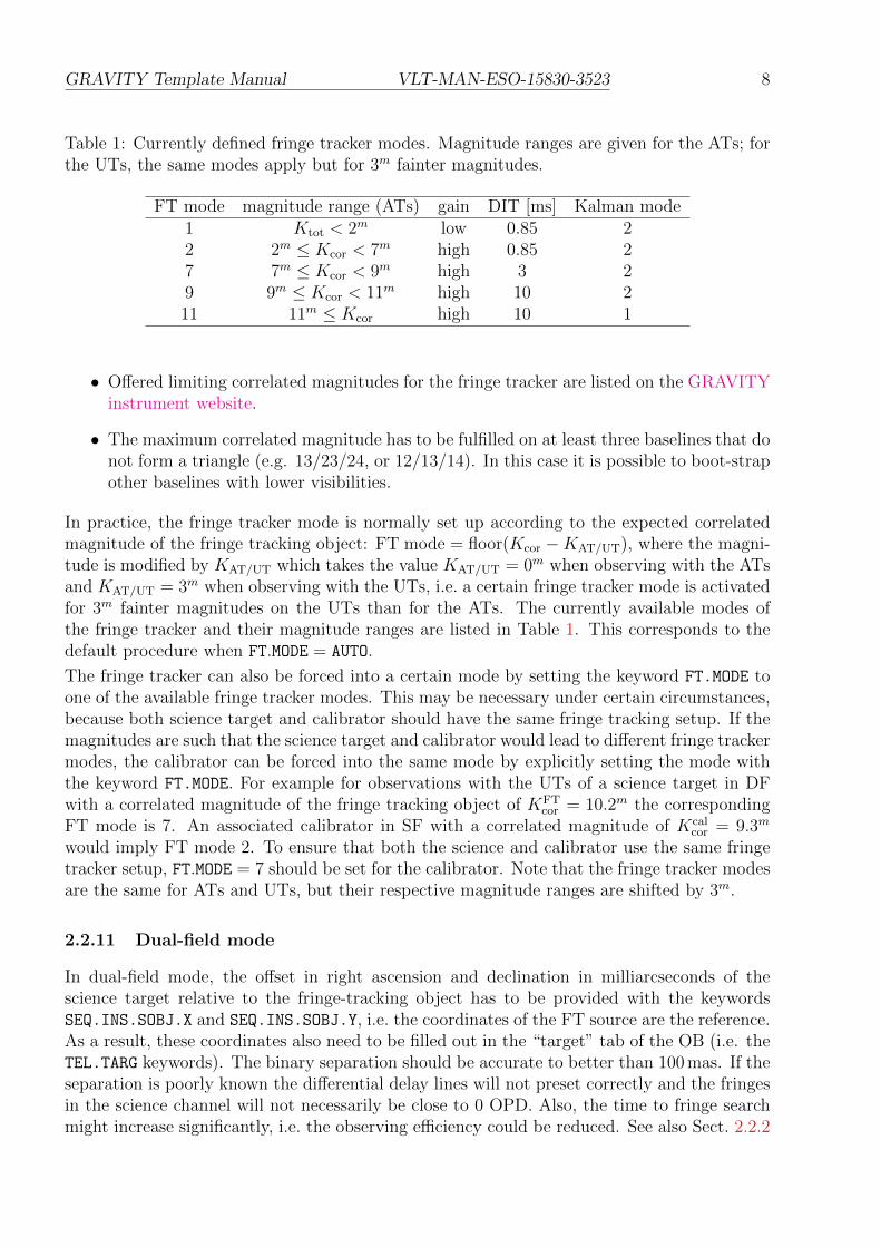
Table 1: Currently defined fringe tracker modes. Magnitude ranges are given for the ATs; forthe UTs, the same modes apply but for 3m fainter magnitudes.
FT mode magnitude range (ATs) gain DIT [ms] Kalman mode1 Ktot < 2m low 0.85 22 2m ≤ Kcor < 7m high 0.85 27 7m ≤ Kcor < 9m high 3 29 9m ≤ Kcor < 11m high 10 211 11m ≤ Kcor high 10 1
• Offered limiting correlated magnitudes for the fringe tracker are listed on the GRAVITYinstrument website.
• The maximum correlated magnitude has to be fulfilled on at least three baselines that donot form a triangle (e.g. 13/23/24, or 12/13/14). In this case it is possible to boot-strapother baselines with lower visibilities.
In practice, the fringe tracker mode is normally set up according to the expected correlatedmagnitude of the fringe tracking object: FT mode = floor(Kcor −KAT/UT), where the magni-tude is modified by KAT/UT which takes the value KAT/UT = 0m when observing with the ATsand KAT/UT = 3m when observing with the UTs, i.e. a certain fringe tracker mode is activatedfor 3m fainter magnitudes on the UTs than for the ATs. The currently available modes ofthe fringe tracker and their magnitude ranges are listed in Table 1. This corresponds to thedefault procedure when FT.MODE = AUTO.
The fringe tracker can also be forced into a certain mode by setting the keyword FT.MODE toone of the available fringe tracker modes. This may be necessary under certain circumstances,because both science target and calibrator should have the same fringe tracking setup. If themagnitudes are such that the science target and calibrator would lead to different fringe trackermodes, the calibrator can be forced into the same mode by explicitly setting the mode withthe keyword FT.MODE. For example for observations with the UTs of a science target in DFwith a correlated magnitude of the fringe tracking object of KFT
cor = 10.2m the correspondingFT mode is 7. An associated calibrator in SF with a correlated magnitude of Kcal
cor = 9.3m
would imply FT mode 2. To ensure that both the science and calibrator use the same fringetracker setup, FT.MODE = 7 should be set for the calibrator. Note that the fringe tracker modesare the same for ATs and UTs, but their respective magnitude ranges are shifted by 3m.
2.2.11 Dual-field mode
In dual-field mode, the offset in right ascension and declination in milliarcseconds of thescience target relative to the fringe-tracking object has to be provided with the keywordsSEQ.INS.SOBJ.X and SEQ.INS.SOBJ.Y, i.e. the coordinates of the FT source are the reference.As a result, these coordinates also need to be filled out in the “target” tab of the OB (i.e. theTEL.TARG keywords). The binary separation should be accurate to better than 100 mas. If theseparation is poorly known the differential delay lines will not preset correctly and the fringesin the science channel will not necessarily be close to 0 OPD. Also, the time to fringe searchmight increase significantly, i.e. the observing efficiency could be reduced. See also Sect. 2.2.2

GRAVITY Template Manual VLT-MAN-ESO-15830-3523 9
for the definition of the FT, SC and Coude guide objects.The requirements for the dual-field mode are:
• Science target correlated K magnitude must not differ more than 3m from the fringe-tracker source.
• The separation between fringe-tracker source and science target must be within the range[0.4′′, 2′.0′] for the UTs and [1.5′′, 4.0′′] for the ATs.
2.3 The observation template
Following the acquistion template, the user has to chose a science observation template. Thistemplate is the second and the last one in any GRAVITY OB. It is used to record the fringeand sky data. There are currently only four templates:
1. single-field science target, GRAVITY single obs exp
2. single-field calibrator, GRAVITY single obs calibrator
3. dual-field science target, GRAVITY dual obs exp
4. dual-field calibrator, GRAVITY dual obs calibrator
The templates use identical keywords. The appropriate template should be chosen accord-ing to the mode (single/dual) and the target (science/calibrator). Each template allows asequence of exposures. The sequence consists of science target exposures (OBJECT) and off-source exposures (SKY). The observing sequence can be defined by the user with the keywordSEQ.OBSSEQ. The sequence can contain any combination of object (O) and sky (S) exposures.The SEQ.SKY.X and SEQ.SKY.Y are used to select the offset of the sky exposure. These off-sets will move the GRAVITY internal actuators in the directions given. Make sure that indual-field the sky offset will not position the SC star on the FT fibre or vice versa. Safest isto offset perpendicular to the binary separation vector.
2.3.1 Integration time
The exposure time for the science spectrometer should be chosen according to the modeand uncorrelated K-band magnitude of the science target. It is specified by the keywordDET2.DIT. Table 2 lists the suggested DITs for the various modes and magnitudes. Thenumber of frames (NDIT) per exposure can be specified with DET2.NDIT.OBJECT for thescience exposure and DET2.NDIT.SKY for the sky exposure.The following requirements apply:
1. The total exposure time (DIT×NDIT) must not exceed 300 s.
2. The number of science frames (NDIT) must not exceed 300 and be more than 10.
Note: Stability of the instrument assessed during the commissioning shows that the DITof the Science and Calibrator targets need not be the same, contrary to VLTI practice andexperience with the other instruments.

GRAVITY Template Manual VLT-MAN-ESO-15830-3523 10
Table 2: Summary of available modes, spectral and polarisation configurations, telescopes(Tel), uncorrelated K magnitudes (K) and suggested DITs for the science spectrometer. In DFthe same DITs are adopted as in single-field except that the appropriate DF DIT correspondsto that of a star 0.7m brighter (Kdf = K − 0.7m). This reflects that in dual-field the light isnot split 50/50 between FT and SC. Likewise for UT observations, one choses a AT SF DITthat corresponds to a star 3 (or 3.7) magnitudes brighter than the UT science target. Notethat the DIT for the calibrator can be different from the one used for the science object.Performances are strongly seeing dependent.
Mode Spec Pol Tel K DIT [s]Single-field MR Comb AT -1.0<K≤1.0 0.3Single-field MR Comb AT 1.0<K≤2.5 1.0Single-field MR Comb AT 2.5<K≤3.0 3.0Single-field MR Comb AT 3.0<K≤3.5 5.0Single-field MR Comb AT 3.5<K≤4.5 10.0Single-field MR Comb AT 5.0<K≤9.0 30.0Single-field MR Split AT -2.0<K≤0.0 0.3Single-field MR Split AT 0.0<K≤1.5 1.0Single-field MR Split AT 1.5<K≤2.5 3.0Single-field MR Split AT 2.5<K≤3.0 5.0Single-field MR Split AT 3.0<K≤4.0 10.0Single-field MR Split AT 4.0<K≤9.0 30.0Single-field HR Comb AT -2.0<K≤-0.5 1.0Single-field HR Comb AT -0.5<K≤0.5 5.0Single-field HR Comb AT 0.5<K≤2.0 10.0Single-field HR Comb AT 2.0<K≤9.0 30.0Single-field HR Split AT -2.0<K≤-0.5 3.0Single-field HR Split AT -0.5<K≤0.0 5.0Single-field HR Split AT 0.0<K≤ 1.0 10.0Single-field HR Split AT 1.0<K≤ 4.5 30.0Dual-field all all AT K − 0.7 -Single-field all all UT K − 3.0 -Dual-field all all UT K − 3.7 -

GRAVITY Template Manual VLT-MAN-ESO-15830-3523 11
2.3.2 Execution time
A conservative estimate of a CAL/SCI sequence is one hour. Each acquisition takes roughly10 min (it can take longer on faint targets). About 20 min have to be spent for object and skyexposures. Note: The calibrator has to be observed with the same configuration and thusthe total execution time for one calibrated visibility spectrum is 60 minutes (SCI-CAL).
The following model for the calculation of the execution time is applied for SF:
exectime = 600 sec + DIT × NDIT × NEXP + 40 sec × NEXP (1)
and for DF:
exectime = 900 sec + DIT × NDIT × NEXP + 40 sec × NEXP, (2)
where NEXP is the number of exposure entered in the observing template keyword SEQ.OBSSEQ.For background limited data, the default is to use the same number of NDIT for S(ky) andO(bject).
A typical example on how to fill the 30 minutes would be the following:
In single-field: If we have a OSO sequence, we have to subtract 600 min offset and 3*40 secoffset, leaving 1080 sec, or 360 seconds for each exposure, which is too much.
So, we typically need to use OSOS, leaving 1040 sec, or 260 sec per exposure. So, for magnitude1 in MR, this would typically be DIT=1s and NDIT=260. Or, for magnitude 1 in HR, thiswould typically be DIT=30s and NDIT=8.
2.3.3 Acquisition camera frames
The internal Acquisition Camera is used for the object acquisition as well as slow pupil andtilt guiding. By default each science exposure contains one acquisition frame (NDIT=1) withan integration time DIT=0.7 s. This means the user obtains an H-band image of the sciencetarget with roughly 4” field-of-view.

GRAVITY Template Manual VLT-MAN-ESO-15830-3523 12
Table 3: Overview of DIT and recommended NDIT values for different number of exposuresfor SF and DF mode. The value DIT×NDIT should be less than 300 seconds, while the totalexecution time of the OB is <=1800 seconds. The number of science frames (NDIT) must notexceed 300.
DIT Nexp NDIT Execution time NDIT Execution time(s) (O S ..) SF SF DF DF1.0 2 300 1280 300 1580
3 300 1620 260 18004 260 1800 185 18005 200 1800 140 1800
3.0 2 100 1280 100 15803 100 1620 85 17854 85 1780 60 17805 65 1775 45 1775
5.0 2 60 1280 60 15803 60 1620 50 17704 50 1760 35 17605 40 1800 25 1725
10.0 2 30 1280 30 15803 30 1620 25 17704 25 1760 18 17805 20 1800 14 1800
30.0 2 10 1280 10 15803 10 1620 - -
GRAVITY Template Manual VLT-MAN-ESO-15830-3523 13
3 TEMPLATE KEYWORDS
In the following tables, we give for each template the keywords that have to be set by the userduring Phase 2 preparation.
3.1 Acquisition templates
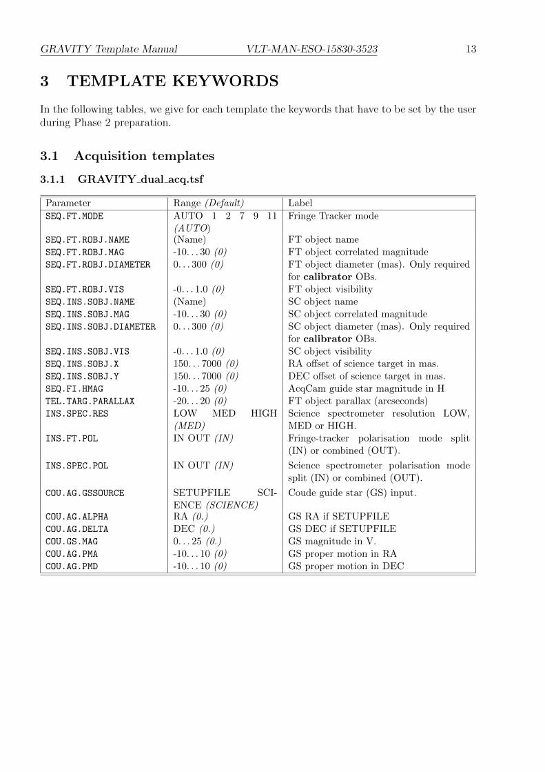
3.1.1 GRAVITY dual acq.tsf
Parameter Range (Default) Label
SEQ.FT.MODE AUTO 1 2 7 9 11(AUTO)
Fringe Tracker mode
SEQ.FT.ROBJ.NAME (Name) FT object nameSEQ.FT.ROBJ.MAG -10. . . 30 (0) FT object correlated magnitudeSEQ.FT.ROBJ.DIAMETER 0. . . 300 (0) FT object diameter (mas). Only required
for calibrator OBs.SEQ.FT.ROBJ.VIS -0. . . 1.0 (0) FT object visibilitySEQ.INS.SOBJ.NAME (Name) SC object nameSEQ.INS.SOBJ.MAG -10. . . 30 (0) SC object correlated magnitudeSEQ.INS.SOBJ.DIAMETER 0. . . 300 (0) SC object diameter (mas). Only required
for calibrator OBs.SEQ.INS.SOBJ.VIS -0. . . 1.0 (0) SC object visibilitySEQ.INS.SOBJ.X 150. . . 7000 (0) RA offset of science target in mas.SEQ.INS.SOBJ.Y 150. . . 7000 (0) DEC offset of science target in mas.SEQ.FI.HMAG -10. . . 25 (0) AcqCam guide star magnitude in HTEL.TARG.PARALLAX -20. . . 20 (0) FT object parallax (arcseconds)INS.SPEC.RES LOW MED HIGH
(MED)Science spectrometer resolution LOW,MED or HIGH.
INS.FT.POL IN OUT (IN) Fringe-tracker polarisation mode split(IN) or combined (OUT).
INS.SPEC.POL IN OUT (IN) Science spectrometer polarisation modesplit (IN) or combined (OUT).
COU.AG.GSSOURCE SETUPFILE SCI-ENCE (SCIENCE)
Coude guide star (GS) input.
COU.AG.ALPHA RA (0.) GS RA if SETUPFILECOU.AG.DELTA DEC (0.) GS DEC if SETUPFILECOU.GS.MAG 0. . . 25 (0.) GS magnitude in V.COU.AG.PMA -10. . . 10 (0) GS proper motion in RACOU.AG.PMD -10. . . 10 (0) GS proper motion in DEC

GRAVITY Template Manual VLT-MAN-ESO-15830-3523 14
3.1.2 GRAVITY single acq.tsf
Parameter Range (Default) Label
SEQ.FT.MODE AUTO 1 2 7 9 11(AUTO)
Fringe Tracker mode
SEQ.INS.SOBJ.NAME (Name) SC object nameSEQ.INS.SOBJ.MAG -10. . . 30 (0) SC object total magnitudeSEQ.INS.SOBJ.DIAMETER 0. . . 300 (0) SC object diameter (mas). Only required
for calibrator OBs.SEQ.INS.SOBJ.VIS -0. . . 1.0 (0) SC object visibilitySEQ.FI.HMAG -10. . . 25 (0) AcqCam guide star magnitude in HTEL.TARG.PARALLAX -20. . . 20 (0) SC object parallax (arcseconds)INS.SPEC.RES LOW MED HIGH
(MED)Science spectrometer resolution LOW,MED or HIGH.
INS.FT.POL IN OUT (IN) Fringe-tracker polarisation mode split(IN) or combined (OUT).
INS.SPEC.POL IN OUT (IN) Science spectrometer polarisation modesplit (IN) or combined (OUT).
COU.AG.GSSOURCE SETUPFILE SCIENCE(SCIENCE)
Coude guide star (GS) input.
COU.AG.ALPHA RA (0.) GS RA if SETUPFILECOU.AG.DELTA DEC (0.) GS DEC if SETUPFILECOU.GS.MAG 0. . . 25 (0.) GS magnitude in V.COU.AG.PMA -10. . . 10 (0) GS proper motion in RACOU.AG.PMD -10. . . 10 (0) GS proper motion in DEC
3.1.3 Acquisition keywords
Below follows a more detailed description of the keywords in the acquisition templates:
• SEQ.FT.MODE: Set the fringe tracker mode automatically depending on the magnitudeof the fringe tracking object (for SEQ.FT.MODE = AUTO), or manually set the mode (seeSect. 2.2.10).
• SEQ.FT.ROBJ.MAG: is the total K magnitude of the fringe-tracking object in dual-fieldmode. This parameter is required to automatically set the mode of the fringe tracker.
• SEQ.FT.ROBJ.DIAMETER: This keyword is only required for calibrator observed in dual-field mode. It is used by the pipeline to correct for the calibrator intrinsic size andvisibility. It is however suggested to observe calibrators in single-field mode (also if usedfor dual-field science targets). Therefore this keyword is normally not required.
• SEQ.FT.ROBJ.VIS: is the expected visibility of the fringe tracking object in dual-fieldmode. In single-field mode, this parameter is required when automatically setting themode of the fringe tracker.
• SEQ.INS.SOBJ.MAG: is the correlated K magnitude of the science target. In single-fieldmode, this parameter is required to automatically set the mode of the fringe tracker.In dual-field mode, this parameter is required to set the parameters for the sciencespectrometer fringe guiding.

GRAVITY Template Manual VLT-MAN-ESO-15830-3523 15
• SEQ.INS.SOBJ.DIAMETER: This keyword is only required for a calibrator (if available).It is used by the pipeline to correct for the calibrator intrinsic size and visibility.
• SEQ.INS.SOBJ.VIS: is the expected visibility of the science target. It is required insingle-field mode when automatically setting the mode of the fringe tracker and in dual-field mode to set the parameters for the science spectrometer fringe guiding.
• SEQ.INS.SOBJ.X/Y: RA/DEC offsets in milli-arcseond of the science target relative tofringe-tracking object. The offsets have to be known to better than 100 mas in order toavoid delays in the fringe search. If this value is calculated from the positions of eachcomponent, the distance in RA (in mas) should include the cos(DEC) term. The offsetshave to be provided for the epoch of the observation. For binaries with high differentialproper motion this offset can change significantly within one period.
• SEQ.FI.HMAG: is the H-band magnitudes of the brightest target in the field (usually thefringe-tracking target). This target will be used for slow field guiding with the AcquisitionCamera.
• TEL.TARG.PARALLAX: This keyword specifies the parallax of the fringe-tracking target.It is required for accurate fringe positioning if the parallax exceeds 100 mas.
• INS.SPEC.RES: This keyword sets the desired SC spectral configuration. It can be:
– LOW: The medium resolution grism is used (R ∼ 20).
– MED: The medium resolution grism is used (R ∼ 500).
– HIGH: The high resolution grism is used (R ∼ 4000).
• INS.FT.POL and INS.SPEC.POL: These keywords set the desired FT and SC polarisationconfiguration. It can be:
– IN: Wollaston prism is moved in. The s and p polarisation are split on the detector.This mode offers the highest visibility accuracy at the cost of higher read noise sincethe light is split over twice as many pixels. This mode is suggested for brightertargets.
– OUT: Wollaston prism is moved out. Both polarisations are combined on the detec-tor. This mode is suggested for very faint targets.
Note: Currently the polarisation setting for FT and SC have to be the same.
• COU.AG.GSSOURCE: This keyword is used to tell the system which source shall be usedfor Coude guiding (see Sect. 2.2.2).
– In single-field mode the keyword can have the following values:
∗ SCIENCE: Coude guiding on the science object. The coordinates are those givenby the RA/DEC fields of the target.
∗ SETUPFILE: Coude guiding on a chosen guide star different from the scienceobject. The coordinates are those given in the COU.AG.ALPHA/DELTA fields inthe acquisition template. Please note the constraints for STRAP/MACAOguide star in Sect. 2.2.4 and 2.2.5 and that these constraints are also pertinentif Coude guiding are attempted on the SCIENCE object.

GRAVITY Template Manual VLT-MAN-ESO-15830-3523 16
– In dual-field mode it must always be SETUPFILE. The coordinates given in COU.AG.
ALPHA/DELTA can either be the fringe-tracking target coordinates or the coordinatesof a different guide star (Sect. 2.2.2).
• COU.AG.ALPHA/DELTA: Coordinates of the Coude guide star. These keywords shouldonly be specified if the keyword COU.AG.GSSOURCE is set to SETUPFILE. Otherwise theyshould be 0.0 as the Coude Guiding will use the science target to guide on.
• COU.GS.MAG: Coude guide star Visual magnitude. This should always be specified. Inthe case of a variable star the faintest magnitude should be given.
• COU.AG.PMA/PMD: RA/DEC proper motion of the Coude guide star in arcsec/year. Thesekeywords should only be specified if the keyword COU.AG.GSSOURCE is set to SETUPFILE.Otherwise they should be 0.0 as the Coude Guiding will use the science target to guideon.
3.2 Observing templates
3.2.1 GRAVITY dual obs exp.tsf
Parameter Range (Default) Label
DET2.DIT 0.3 1 3 5 10 30 60 100 300 (0.3) SC frame integration time (DIT in s)DET2.NDIT.OBJECT 10. . . 300 (25) Number of science target frames (NDIT)DET2.NDIT.SKY 10. . . 300 (25) Number of sky frames (NDIT)SEQ.RELOFF.X -1000..1000 (0.0) Sequence of SC relative RA offsets (mas)SEQ.RELOFF.Y -1000..1000 (0.0) Sequence of SC relative DEC offsets
(mas)SEQ.SKY.X -2000. . . 2000 (2000) Sky offset in RA (mas).SEQ.SKY.Y -2000. . . 2000 (2000) Sky offset in DEC (mas).SEQ.OBSSEQ O S (O S) Observing sequence of science (O) and
sky (S) exposures.
3.2.2 GRAVITY dual obs calibrator.tsf and GRAVITY single obs *.tsf
All remaining observing templates, GRAVITY dual obs calibrator.tsf, GRAVITY single obs-exp.tsf and GRAVITY single obs calibrator.tsf, use the same set of keywords.
Parameter Range (Default) Label
DET2.DIT 0.3 1 3 5 10 30 60 100 300 (0.3) SC frame integration time (DIT in s)DET2.NDIT.OBJECT 10. . . 300 (25) Number of science target frames (NDIT)DET2.NDIT.SKY 10. . . 300 (25) Number of sky frames (NDIT)SEQ.SKY.X -2000. . . 2000 (1000) Sky offset in RA (mas).SEQ.SKY.Y -2000. . . 2000 (1000) Sky offset in DEC (mas).SEQ.OBSSEQ O S (O S) Observing sequence of science (O) and
sky (S) exposures.
3.2.3 Observing keywords
A detailed explanation of the keywords in the observing template follows:
GRAVITY Template Manual VLT-MAN-ESO-15830-3523 17
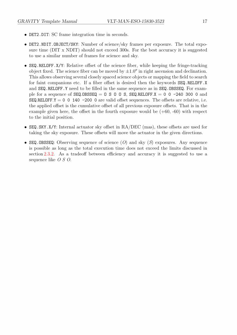
• DET2.DIT: SC frame integration time in seconds.
• DET2.NDIT.OBJECT/SKY: Number of science/sky frames per exposure. The total expo-sure time (DIT x NDIT) should not exceed 300s. For the best accuracy it is suggestedto use a similar number of frames for science and sky.
• SEQ.RELOFF.X/Y: Relative offset of the science fiber, while keeping the fringe-trackingobject fixed. The science fiber can be moved by ±1.0′′ in right ascension and declination.This allows observing several closely spaced science objects or mapping the field to searchfor faint companions etc. If a fiber offset is desired then the keywords SEQ.RELOFF.X
and SEQ.RELOFF.Y need to be filled in the same sequence as in SEQ.OBSSEQ. For exam-ple for a sequence of SEQ.OBSSEQ = O S O O S, SEQ.RELOFF.X = 0 0 -240 300 0 andSEQ.RELOFF.Y = 0 0 140 -200 0 are valid offset sequences. The offsets are relative, i.e.the applied offset is the cumulative offset of all previous exposure offsets. That is in theexample given here, the offset in the fourth exposure would be (+60, -60) with respectto the initial position.
• SEQ.SKY.X/Y: Internal actuator sky offset in RA/DEC (mas), these offsets are used fortaking the sky exposure. These offsets will move the actuator in the given directions.
• SEQ.OBSSEQ: Observing sequence of science (O) and sky (S) exposures. Any sequenceis possible as long as the total execution time does not exceed the limits discussed insection 2.3.2. As a tradeoff between efficiency and accuracy it is suggested to use asequence like O S O.

GRAVITY Template Manual VLT-MAN-ESO-15830-3523 18
oOo