GRAVITY CONVEYOR · SPEC SHEET CATALOG Ultimation Industries LLC 15935 Sturgeon St. Roseville, MI...
19
SPEC SHEET CATALOG Ultimation Industries LLC 15935 Sturgeon St. Roseville, MI 48066 Ph. +1-586-771-1881 ultimationinc.com GRAVITY CONVEYOR
Transcript of GRAVITY CONVEYOR · SPEC SHEET CATALOG Ultimation Industries LLC 15935 Sturgeon St. Roseville, MI...
SPEC SHEET CATALOG
Ul t imat ion Indust r ies LLC
15935 Stu rgeon St.Rosev i l le, MI 48066
Ph. +1-586-771-1881
ul t imat ion inc.com
GRAVITY CONVEYOR
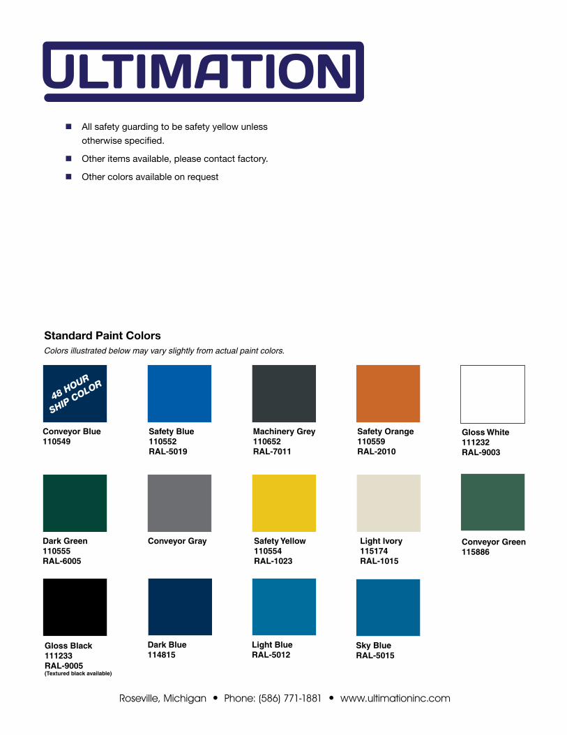
Safety Orange110559RAL-2010
Machinery Grey 110652RAL-7011
Safety Blue110552RAL-5019
Conveyor Blue110549
Dark Green110555RAL-6005
Conveyor Gray Safety Yellow110554RAL-1023
Light Ivory 115174RAL-1015
Gloss Black111233RAL-9005(Textured black available)
Gloss White111232RAL-9003
Colors illustrated below may vary slightly from actual paint colors.
Standard Paint Colors
Conveyor Green115886
nAll safety guarding to be safety yellow unless
otherwise specified.
nOther items available, please contact factory.
nOther colors available on request
Dark Blue 114815
Light BlueRAL-5012
Sky BlueRAL-5015
48 HOUR
SHIP COLOR
Roseville, Michigan • Phone: (586) 771-1881 • www.ultimationinc.com

TABLE OF CONTENTSBELT CONVEYORS
Horizontal belt conveyor ............................................................... 1-8
Belt curve .........................................................................................9
Incline belt conveyor ..................................................................10-13
Incline dimensional chart ................................................................14
Bed and undertrussing information .................................................15
Troughed belt conveyor..............................................................16-19
LIVE ROLLER CONVEYORS
Belt driven live roller conveyor (transportation) ..........................20-21
Belt driven live roller conveyor (minimum pressure) ...................22-23
Belt driven live roller conveyor (zero pressure) ...................... 23A-23B
Flat motor conveyor (transportation) ..................................... 23C-23E
Flat motor conveyor (zero pressure) ...................................... 23F-23H
V-belt driven live roller conveyor (minimum pressure) ................24-39
Lineshaft conveyor .....................................................................40-43
Chain driven live roller conveyor (transportation) .......................44-54
CHAIN CONVEYORS
Drag chain conveyor (transportation) .........................................55-58
GRAVITY CONVEYOR
Skatewheel conveyor .................................................................59-61
Gravity roller conveyor ...............................................................62-72
Ball transfer table ...........................................................................73
Conveyor rail...................................................................................74
ACCESSORIES
Supports ....................................................................................75-78
Guide rails ......................................................................................79
Stops .........................................................................................80-82
Gates .........................................................................................83-84
ELECTRICAL CONTROLS
ProLogic Accumulation System ..................................................85-86
Roseville, Michigan • Phone: (586) 771-1881 • www.ultimationinc.com

59Roseville, Michigan • Phone: (586) 771-1881 • www.ultimationinc.com
WSS/WASGravity skatewheel conveyor is ideal for conveying light packages or for applications where conveyor portability is desired. They are useful for temporary conveyor lines in assembly and delivery operations.
STEEL FRAMES12" OAW 15" OAW 18" OAW 24" OAW
MODEL NO. WPFWT. (LBS.)
MODEL NO. WPFWT. (LBS.)
MODEL NO. WPFWT. (LBS.)
MODEL NO. WPFWT. (LBS.)
5' 10' 5' 10' 5' 10' 5' 10'
WSS3-12-10 10 37 70 WSS3-15-10 10 40 73 WSS3-18-16 16 46 87 WSS3-24-20 20 57 103
WSS3-12-12 12 39 74 WSS3-15-12 12 43 78 WSS3-18-18 18 49 92 WSS3-24-24 24 62 112
WSS3-12-16 16 42 81 WSS3-15-16 16 48 87 WSS3-18-20 20 54 98 WSS3-24-28 28 65 118
n 4 widths n Powder coated steel or aluminum frames n Portable or permanent installation
STANDARD SPECIFICATIONSFRAME - 2 1/2 in. deep x 1 in. flange x 12 ga. powder coated steel or 1/8 in. aluminum channel with bolt-in cross members
WIDTHS - 12 in., 15 in., 18 in., and 24 in. overall width
LENGTHS - 5 ft. and 10 ft. straight sections
COUPLINGS - Bolts one end, hooks on opposite end
WHEELS - 1 15/16 in. dia. ball bearings run in hardened raceway with life time lubrication. Corrosion-resistant aluminum or zinc plated steel.
AXLES - 1/4 in. dia. threaded one end with locknut on 3 in. centers
LOAD CAPACITY (LBS.)
FRAME MATERIAL
SUPPORT CENTERS
FRAME CAPACITY WHEEL CAPACITY
MAX. DISTRIBUTED LIVE LOAD PER FOOT
MAX. STATIC LOAD PER WHEEL
STEEL5' 260
6510' 35
ALUMINUM5' 142
5010' 16
GRAVITY SKATEWHEEL CONVEYOR
OPTIONAL EQUIPMENTSUPPORTS - Portable Tripod Supports, portable T-stand carriages and stationary floor supports are available in a wide range of adjust-ments
LENGTHS - Other lengths from 2 ft. to 10 ft.
WIDTHS - Other in-between widths from 12 in. to 30 in. overall width
WHEELS / COVERS - Black or white plastic wheels are available in place of steel or aluminum wheels. Black neoprene covers are also available.
BUTT COUPLINGS - In place of hooks and bolts, these brackets allow a more permanent connection with adjacent conveyor
GUIDE RAILS - Adjustable channel guide rails, fixed angle and channel guide rails
BETWEEN FRAME WIDTH
OVERALL WIDTH
1"
2-1/2"
3/8"
CROSS MEMBERAXLE AND SPACERS CENTER SUPPORT BARS
ALUMINUM FRAMES12" OAW 15" OAW 18" OAW 24" OAW
MODEL NO. WPFWT. (LBS.)
MODEL NO. WPFWT. (LBS.)
MODEL NO. WPFWT. (LBS.)
MODEL NO. WPFWT. (LBS.)
5' 10' 5' 10' 5' 10' 5' 10'
WAS3-12-10 10 20 36 WAS3-15-10 10 22 39 WAS3-18-16 16 25 46 WAS3-24-20 20 30 55
WAS3-12-12 12 21 39 WAS3-15-12 12 23 41 WAS3-18-18 18 27 49 WAS3-24-24 24 32 59
WAS3-12-16 16 23 43 WAS3-15-16 16 26 43 WAS3-18-20 20 28 52 WAS3-24-28 28 34 63
OVERALL LENGTH 1-9/16"
COUPLING BOLT GRAVITY HOOKCROSS MEMBER

60Roseville, Michigan • Phone: (586) 771-1881 • www.ultimationinc.com
2-1/2"
3/8"
WSC/WACGravity skatewheel curves are compatible with straight section providing flexibility to your conveyor line. The differential action of wheels assures proper orientation of packages.
STEEL FRAMES12" OAW 15" OAW 18" OAW 24" OAW
MODEL NO. DEGREE WPC WT. (LBS.) MODEL NO. DEGREE WPC WT. (LBS.) MODEL NO. DEGREE WPC WT. (LBS.) MODEL NO. DEGREE WPC WT. (LBS.)
WSC-12-30 30 30 14 WSC-15-30 30 40 16 WSC-18-30 30 45 18 WSC-24-30 30 60 23
WSC-12-45 45 30 21 WSC-15-45 45 40 23 WSC-18-45 45 45 25 WSC-24-45 45 78 37
WSC-12-60 60 42 30 WSC-15-60 60 56 35 WSC-18-60 60 63 37 WSC-24-60 60 102 54
WSC-12-90 90 63 40 WSC-15-90 90 84 46 WSC-18-90 90 94 49 WSC-24-90 90 156 72
n 4 widths n Powder coated steel or aluminum frames n 30, 45, 60 and 90 degree curves
STANDARD SPECIFICATIONSFRAME - 2 1/2 in. deep x 1 in. flange x 12 ga. powder coated steel or 1/8 in. aluminum channel with bolt-in cross members
WIDTHS - 12 in., 15 in., 18 in., and 24 in. overall width
CURVES - 30, 45, 60 and 90 degree curves. See radius chart
COUPLINGS - Hooks and bolts on both ends of curve
WHEELS - 1 15/16 in. dia., ball bearings run in hardened raceway with life time lubrication. Corrosion-resistant aluminum or zinc plated steel.
AXLES - 1/4 in. dia. threaded one end with locknut on 3 in. equivalent centers
RADIUSOVERALL WIDTH INSIDE RADIUS OUTSIDE RADIUS
12" 36" 48"
15" 33" 48"
18" 30" 48"
24" 36" 60"
GRAVITY SKATEWHEEL CURVE CONVEYOR
ALUMINUM FRAMES12" OAW 15" OAW 18" OAW 24" OAW
MODEL NO. DEGREE WPC WT. (LBS.) MODEL NO. DEGREE WPC WT. (LBS.) MODEL NO. DEGREE WPC WT. (LBS.) MODEL NO. DEGREE WPC WT. (LBS.)
WAC-12-30 30 30 8 WAC-15-30 30 40 9 WAC-18-30 30 45 10 WAC-24-30 30 60 14
WAC-12-45 45 30 12 WAC-15-45 45 40 14 WAC-18-45 45 45 15 WAC-24-45 45 78 23
WAC-12-60 60 42 17 WAC-15-60 60 56 20 WAC-18-60 60 63 21 WAC-24-60 60 102 33
WAC-12-90 90 63 22 WAC-15-90 90 84 26 WAC-18-90 90 94 28 WAC-24-90 90 156 43
OPTIONAL EQUIPMENTSUPPORTS - Tripod Supports, portable T-stand carriages and sta-tionary floor supports are available in a wide range of adjustments
SPECIAL DEGREE CURVES - Contact factory
WIDTHS - Other in-between widths from 12 in. to 30 in. overall width
WHEELS/COVERS - Black or white plastic wheels are available in place of steel or aluminum wheels. Black neoprene covers are also available.
BUTT COUPLINGS - In place of hooks and bolts, these brackets allow a more permanent connection with adjacent conveyor
GUIDE RAILS - Adjustable channel guide rails, fixed angle and channel guide rails
INSIDE RADIUS
OUTSIDE RADIUS
BETWEEN FRAME WIDTH
OVERALL WIDTH
1"
CROSS MEMBERAXLE AND SPACERS CENTER SUPPORT BARS

61Roseville, Michigan • Phone: (586) 771-1881 • www.ultimationinc.com
WSL/WSR WAL/WARGravity skatewheel spurs are used to transfer product from one conveying line onto another. They are suitable for merging or diverging applications.
STEEL FRAMES
OAW30° SPUR 45° SPUR 90° SPUR
MODEL NO. "A" WPS WT. (LBS.) MODEL NO. "A" WPS WT. (LBS.) MODEL NO. "A" "B" "R" WPS WT. (LBS.)
12" WS(L/R)-12-30 24 3/8" 51 39 WS(L/R)-12-45 21" 54 39 WS(L/R)-12-90 30" 39 1/8" 36" 46 67
15" WS(L/R)-15-30 30 3/8" 67 43 WS(L/R)-15-45 30" 70 43 WS(L/R)-15-90 39" 35 5/8" 33" 56 72
18" WS(L/R)-18-30 36 3/8" 71 47 WS(L/R)-18-45 30" 77 47 WS(L/R)-18-90 39" 32 11/16" 30" 60 77
24" WS(L/R)-24-30 48 3/8" 83 57 WS(L/R)-24-45 39" 97 57 WS(L/R)-24-90 51" 39 1/2" 36" 94 107
n 4 widths
n Powder coated steel or aluminum frames
n 30, 45 and 90 degree spurs
STANDARD SPECIFICATIONSFRAME – 2 1/2 in. deep x 1 in. flange x 12 ga. powder coated steel or 1/8 in. aluminum channel with bolt-in cross members
WIDTHS – 12 in., 15 in., 18 in., and 24 in. overall width
SPUR ANGLES - 30, 45 and 90 degree. Specify right hand or left hand.
COUPLINGS – Hooks and bolts one end. Shelf angle on the opposite end. Specify shelf angle mounting bracket.
WHEELS – 1 15/16 in. dia., ball bearings run in hardened raceway with life time lubrication. Corrosion-resistant aluminum or zinc plated steel.
AXLES – 1/4 in. dia. threaded one end with locknut on 3 in. centers
GRAVITY SKATEWHEEL SPUR CONVEYOR
OPTIONAL EQUIPMENTSUPPORTS – Tripod stands and stationary floor supports are avail-able in a wide range of adjustments
WIDTHS – Other in-between widths from 12 in. to 30 in. overall width
WHEELS/COVERS – Black or white plastic wheels are available in place of steel or aluminum wheels. Black neoprene covers are also available.
BUTT COUPLINGS – In place of hooks and bolts, these brackets allow a more permanent connection with adjacent conveyor
GUIDE RAILS – Adjustable channel guide rails, fixed angle and channel guide rails
ALUMINUM FRAMES
OAW30° SPUR 45° SPUR 90° SPUR
MODEL NO. "A" WPS WT. (LBS.) MODEL NO. "A" WPS WT. (LBS.) MODEL NO. "A" "B" "R" WPS WT. (LBS.)
12" WA(L/R)-12-30 24 3/8" 51 26 WA(L/R)-12-45 21" 54 26 WA(L/R)-12-90 30" 39 1/8" 36" 46 45
15" WA(L/R)-15-30 30 3/8" 67 29 WA(L/R)-15-45 30" 70 29 WA(L/R)-15-90 39" 35 5/8" 33" 56 47
18" WA(L/R)-18-30 36 3/8" 71 32 WA(L/R)-18-45 30" 77 32 WA(L/R)-18-90 39" 32 11/16" 30" 60 51
24" WA(L/R)-24-30 48 3/8" 83 38 WA(L/R)-24-45 39" 97 38 WA(L/R)-24-90 51" 39 1/2" 36" 94 71
30°/45° 90°
RIGHT HAND LEFT HANDRIGHT HAND LEFT HAND
SECTION VIEW X-X
CONVEYOR CHANNEL SIZE "H"
ORDER BY MOUNTING BRACKET NO.
2 1/2 x 12 ga. Steel ATL-10313
3 1/2 x 10 ga. Steel ATL-11745
6 1/2 x 12 ga. Steel ATL-13082
H
MOUNTING BRACKET
X
90°
"R""B"
"A"
43-3/8" 60"
60"
31-5/32"
45°30°
"A" "A"
X
SHELF ANGLE

62Roseville, Michigan • Phone: (586) 771-1881 • www.ultimationinc.com
Gravity roller conveyor is ideal for conveying light packages or for applications where conveyor portability is desired. They are useful for temporary or permanent conveyor lines in assembly and warehouse operations.
STEEL FRAMES12" OAW 15" OAW 18" OAW 24" OAW
MODEL NO.ROLL
CENTERSWT. (LBS.)
MODEL NO.ROLL
CENTERSWT. (LBS.)
MODEL NO.ROLL
CENTERSWT. (LBS.)
MODEL NO.ROLL
CENTERSWT. (LBS.)
5' 10' 5' 10' 5' 10' 5' 10'
RS14G-12-1.5 1 1/2" 55 101 RS14G-15-1.5 1 1/2" 62 112 RS14G-18-1.5 1 1/2" 72 135 RS14G-24-1.5 1 1/2" 91 168
RS14G-12-3 3" 37 68 RS14G-15-3 3" 42 78 RS14G-18-3 3" 47 97 RS14G-24-3 3" 58 108
RS14G-12-4.5 4 1/2" 32 58 RS14G-15-4.5 4 1/2" 33 61 RS14G-18-4.5 4 1/2" 40 73 RS14G-24-4.5 4 1/2" 47 88
RS14G-12-6 6" 29 52 RS14G-15-16 6" 30 55 RS14G-18-6 6" 32 63 RS14G-24-6 6" 42 78
n 4 widths n Powder coated steel or aluminum frames n Portable or permanent installation
STANDARD SPECIFICATIONSFRAME - 2 1/2 in. deep x 1 in. flange x 12 ga. powder coated steel or 1/8 in. aluminum channel with bolt-in cross members
WIDTHS - 12 in., 15 in., 18 in., and 24 in. overall width
LENGTHS - 5 ft. and 10 ft. straight sections
COUPLINGS - Bolts one end, hooks on opposite end
ROLLERS - 1 3/8 in. dia. x 18 ga. galvanized steel or heat treated aluminum tube, 1/4 in. dia. spring retained axle, oiled ball bearings both ends
ROLLER CENTERS - 1 1/2 in., 3 in., 4 1/2 in., or 6 in. centers
GRAVITY ROLLER CONVEYOR (1 3/8 in. dia. x 18 ga. rollers)
OPTIONAL EQUIPMENTSUPPORTS - Tripod supports, portable T-stand carriages and station-ary floor supports are available in a wide range of adjustments
LENGTHS - Other lengths from 2 ft. to 10 ft.
WIDTHS - Other in-between widths from 12 in. to 30 in. overall width
BUTT COUPLINGS - In place of hooks and bolts, these brackets allow a more permanent connection with adjacent conveyor
GUIDE RAILS - Adjustable channel guide rails, fixed angle and channel guide rails
BETWEEN FRAME WIDTH
OVERALL WIDTH
1"
2-1/2"
3/32"
CROSS MEMBER1-3/8" DIA. ROLLER
ALUMINUM FRAMES12" OAW 15" OAW 18" OAW 24" OAW
MODEL NO.ROLL
CENTERSWT. (LBS.)
MODEL NO.ROLL
CENTERSWT. (LBS.)
MODEL NO.ROLL
CENTERSWT. (LBS.)
MODEL NO.ROLL
CENTERSWT. (LBS.)
5' 10' 5' 10' 5' 10' 5' 10'
RS14A-12-1.5 1 1/2" 29 53 RS14A-15-1.5 1 1/2" 33 56 RS14A-18-1.5 1 1/2" 38 70 RS14A-24-1.5 1 1/2" 48 88
RS14A-12-3 3" 20 36 RS14A-15-3 3" 23 41 RS14A-18-3 3" 27 51 RS14A-24-3 3" 30 56
RS14A-12-4.5 4 1/2" 17 30 RS14A-15-4.5 4 1/2" 18 32 RS14A-18-4.5 4 1/2" 20 38 RS14A-24-4.5 4 1/2" 25 46
RS14A-12-6 6" 15 27 RS14A-15-16 6" 16 29 RS14A-18-6 6" 18 33 RS14A-24-6 6" 22 41
OVERALL LENGTH 1-9/16"
COUPLING BOLT GRAVITY HOOKCROSS MEMBER
RS14
FRAME CAPACITY
FRAMEMATERIAL
SUPPORTCENTERS
MAX. DISTRIBUTEDLIVE LOAD PER FOOT
Steel5' 260
10' 35
Aluminum5' 142
10' 16
ROLLER CAPACITY
BETWEEN FRAMES
MAX. STATIC LOAD PER ROLLER (LBS.)
10" 85
13" 65
16" 50
22" 35
28" 25

63Roseville, Michigan • Phone: (586) 771-1881 • www.ultimationinc.com
2-1/2"
3/32"
Gravity roller curves are compatible with straight sections providing flexibility to your conveyor line. Curves will convey product with a minimum amount of pitch based on weight and size.
STEEL FRAMES12" OAW 15" OAW 18" OAW 24" OAW
MODEL NO. DEGREE WT. (LBS.) MODEL NO. DEGREE WT. (LBS.) MODEL NO. DEGREE WT. (LBS.) MODEL NO. DEGREE WT. (LBS.)
RC14G-12-3-30 30 18 RC14G-15-3-30 30 22 RC14G-18-3-30 30 26 RC14G-24-3-30 30 42
RC14G-12-3-45 45 35 RC14G-15-3-45 45 40 RC14G-18-3-45 45 44 RC14G-24-3-45 45 66
RC14G-12-3-60 60 52 RC14G-15-3-60 60 53 RC14G-18-3-60 60 62 RC14G-24-3-60 60 108
RC14G-12-3-90 90 70 RC14G-15-3-90 90 75 RC14G-18-3-90 90 80 RC14G-24-3-90 90 141
n 4 widths n Powder coated steel or aluminum frames n 30, 45, 60 and 90 degree curves
STANDARD SPECIFICATIONSFRAME - 2 1/2 in. deep x 1 in. flange x 12 ga. powder coated steel or 1/8 in. aluminum channel with bolt-in cross members.
WIDTHS - 12 in., 15 in., 18 in. and 24 in. overall width
CURVES - 30, 45, 60 and 90 degree curves. See radius chart
COUPLINGS - Hooks and bolts on both ends of curve
ROLLERS - Straight or tapered, oiled ball bearings both ends • Straight rollers - 1 3/8 in. dia. x 18 ga. galvanized steel or heat treated aluminum tube, 1/4 in. dia. spring retained axle • Tapered rollers - 1 1/2 in. dia. large end, galvanized steel tapered tube, 5/16 in. spring retained hex axle
ROLLER CENTERS - 3 in. equivalent centers
RADIUSSTRAIGHT ROLLERS TAPERED ROLLERS
OVERALL WIDTH INSIDE RADIUS OUTSIDE RADIUS INSIDE RADIUS OUTSIDE RADIUS
12" 24" 36" 24" 36"
15" 24" 39" 24" 39"
18" 24" 42" 24" 42"
24" 24" 48" 31 1/2" 55 1/2"
ALUMINUM FRAMES12" OAW 15" OAW 18" OAW 24" OAW
MODEL NO. DEGREE WT. (LBS.) MODEL NO. DEGREE WT. (LBS.) MODEL NO. DEGREE WT. (LBS.) MODEL NO. DEGREE WT. (LBS.)
RC14A-12-3-30 30 8 RC14A-15-3-30 30 10 RC14A-18-3-30 30 12 RC14A-24-3-30 30 14
RC14A-12-3-45 45 14 RC14A-15-3-45 45 17 RC14A-18-3-45 45 18 RC14A-24-3-45 45 26
RC14A-12-3-60 60 21 RC14A-15-3-60 60 24 RC14A-18-3-60 60 27 RC14A-24-3-60 60 38
RC14A-12-3-90 90 28 RC14A-15-3-90 90 31 RC14A-18-3-90 90 35 RC14A-24-3-90 90 50
OPTIONAL EQUIPMENTSUPPORTS - Tripod supports, portable T-stand carriages and station-ary floor supports are available in a wide range of adjustments
SPECIAL DEGREE CURVES - Contact factory
WIDTHS - Other in-between widths from 12 in. to 30 in. overall width
ROLLER CENTERS - 1 1/2 in. equivalent centers
BUTT COUPLINGS - In place of hooks and bolts, these brackets allow a more permanent connection with adjacent conveyor
GUIDE RAILS - Adjustable channel guide rails, fixed angle and channel guide rails
INSIDE RADIUS
OUTSIDE RADIUS
RC14
STEEL FRAMES - TAPERED ROLLERS12" OAW 15" OAW 18" OAW 24" OAW
MODEL NO. DEGREE WT. (LBS.) MODEL NO. DEGREE WT. (LBS.) MODEL NO. DEGREE WT. (LBS.) MODEL NO. DEGREE WT. (LBS.)
RC14G-12-3-30T 30 18 RC14G-15-3-30T 30 22 RC14G-18-3-30T 30 26 RC14G-24-3-30T 30 42
RC14G-12-3-45T 45 35 RC14G-15-3-45T 45 40 RC14G-18-3-45T 45 44 RC14G-24-3-45T 45 66
RC14G-12-3-60T 60 52 RC14G-15-3-60T 60 53 RC14G-18-3-60T 60 62 RC14G-24-3-60T 60 108
RC14G-12-3-90T 90 70 RC14G-15-3-90T 90 75 RC14G-18-3-90T 90 80 RC14G-24-3-90T 90 141
BETWEEN FRAME WIDTH
OVERALL WIDTH
1"
CROSS MEMBER1-3/8" DIA. ROLLER
GRAVITY ROLLER CURVE CONVEYOR (1 3/8 in. dia. x 18 ga. rollers)
64Roseville, Michigan • Phone: (586) 771-1881 • www.ultimationinc.com
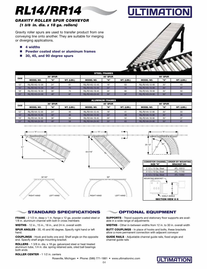
Gravity roller spurs are used to transfer product from one conveying line onto another. They are suitable for merging or diverging applications.
STEEL FRAMES
OAW30° SPUR 45° SPUR 90° SPUR
MODEL NO. "A" WT. (LBS.) MODEL NO. "A" WT. (LBS.) MODEL NO. "A" WT. (LBS.)
12" R(L/R)14G-12-30 24" 61 R(L/R)14G-12-45 18" 63 R(L/R)14G-12-90 35" 43
15" R(L/R)14G-15-30 30" 70 R(L/R)14G-15-45 22" 73 R(L/R)14G-15-90 35" 47
18" R(L/R)14G-18-30 36" 75 R(L/R)14G-18-45 26" 80 R(L/R)14G-18-90 35" 50
24" R(L/R)14G-24-30 48" 87 R(L/R)14G-24-45 35" 97 R(L/R)14G-24-90 50" 58
n 4 widths n Powder coated steel or aluminum frames n 30, 45, and 90 degree spurs
STANDARD SPECIFICATIONSFRAME - 2 1/2 in. deep x 1 in. flange x 12 ga. powder coated steel or 1/8 in. aluminum channel with bolt-in cross members
WIDTHS - 12 in., 15 in., 18 in., and 24 in. overall width
SPUR ANGLES - 30, 45 and 90 degree. Specify right hand or left hand.
COUPLINGS - Hook and bolts one end. Shelf angle on the opposite end. Specify shelf angle mounting bracket.
ROLLERS - 1 3/8 in. dia. x 18 ga. galvanized steel or heat treated aluminum tube, 1/4 in. dia. spring retained axle, oiled ball bearings both ends
ROLLER CENTER - 1 1/2 in. centers
OPTIONAL EQUIPMENTSUPPORTS - Tripod supports and stationary floor supports are avail-able in a wide range of adjustments
WIDTHS - Other in-between widths from 12 in. to 30 in. overall width
BUTT COUPLINGS - In place of hooks and bolts, these brackets allow a more permanent connection with adjacent conveyor
GUIDE RAILS - Adjustable channel guide rails, fixed angle and channel guide rails
ALUMINUM FRAMES
OAW30° SPUR 45° SPUR 90° SPUR
MODEL NO. "A" WT. (LBS.) MODEL NO. "A" WT. (LBS.) MODEL NO. "A" WT. (LBS.)
12" R(L/R)14A-12-30 24" 40 R(L/R)14A-12-45 18" 41 R(L/R)14A-12-90 35" 33
15" R(L/R)14A-15-30 30" 46 R(L/R)14A-15-45 22" 48 R(L/R)14A-15-90 35" 35
18" R(L/R)14A-18-30 36" 50 R(L/R)14A-18-45 26" 52 R(L/R)14A-18-90 35" 37
24" R(L/R)14A-24-30 48" 58 R(L/R)14A-24-45 35" 63 R(L/R)14A-24-90 50" 41
30°/45° 90°
RIGHT HAND LEFT HANDRIGHT HAND LEFT HAND
SECTION VIEW X-X
CONVEYOR CHANNEL SIZE "H"
ORDER BY MOUNTING BRACKET NO.
2 1/2 x 12 Ga. Steel ATL-10313
3 1/2 x 10 Ga. Steel ATL-11745
6 1/2 x 12 Ga. Steel ATL-13082
H
MOUNTING BRACKET
X
90°
24"25-1/2"
"A"
43-3/16" 60"
60"
31"
"A" "A"
X
SHELF ANGLE
RL14/RR14GRAVITY ROLLER SPUR CONVEYOR (1 3/8 in. dia. x 18 ga. rollers)
65Roseville, Michigan • Phone: (586) 771-1881 • www.ultimationinc.com
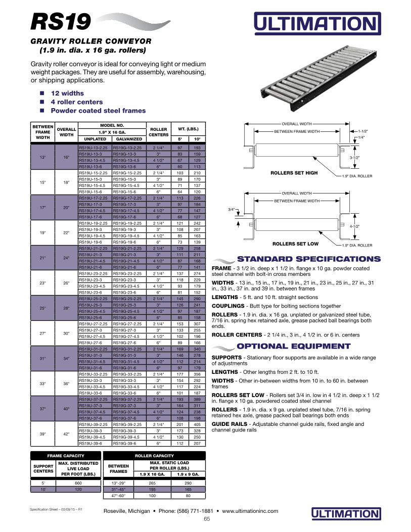
Gravity roller conveyor is ideal for conveying light or medium weight packages. They are useful for assembly, warehousing, or shipping applications.
BETWEENFRAMEWIDTH
OVERALLWIDTH
MODEL NO.ROLLER
CENTERSWT. (LBS.)
1.9" X 16 GA.
UNPLATED GALVANIZED 5' 10'
13" 16"
RS19U-13-2.25 RS19G-13-2.25 2 1/4" 97 193
RS19U-13-3 RS19G-13-3 3" 83 159
RS19U-13-4.5 RS19G-13-4.5 4 1/2" 67 129
RS19U-13-6 RS19G-13-6 6" 60 113
15" 18"
RS19U-15-2.25 RS19G-15-2.25 2 1/4" 103 210
RS19U-15-3 RS19G-15-3 3" 89 170
RS19U-15-4.5 RS19G-15-4.5 4 1/2" 71 137
RS19U-15-6 RS19G-15-6 6" 64 120
17" 20"
RS19U-17-2.25 RS19G-17-2.25 2 1/4" 113 226
RS19U-17-3 RS19G-17-3 3" 97 184
RS19U-17-4.5 RS19G-17-4.5 4 1/2" 77 147
RS19U-17-6 RS19G-17-6 6" 68 127
19" 22"
RS19U-19-2.25 RS19G-19-2.25 2 1/4" 121 242
RS19U-19-3 RS19G-19-3 3" 108 207
RS19U-19-4.5 RS19G-19-4.5 4 1/2" 85 163
RS19U-19-6 RS19G-19-6 6" 73 139
21" 24"
RS19U-21-2.25 RS19G-21-2.25 2 1/4" 129 258
RS19U-21-3 RS19G-21-3 3" 111 211
RS19U-21-4.5 RS19G-21-4.5 4 1/2" 87 168
RS19U-21-6 RS19G-21-6 6" 77 141
23" 26"
RS19U-23-2.25 RS19G-23-2.25 2 1/4" 137 274
RS19U-23-3 RS19G-23-3 3" 118 229
RS19U-23-4.5 RS19G-23-4.5 4 1/2" 93 179
RS19U-23-6 RS19G-23-6 6" 81 152
25" 28"
RS19U-25-2.25 RS19G-25-2.25 2 1/4" 145 290
RS19U-25-3 RS19G-25-3 3" 126 241
RS19U-25-4.5 RS19G-25-4.5 4 1/2" 97 187
RS19U-25-6 RS19G-25-6 6" 85 158
27" 30"
RS19U-27-2.25 RS19G-27-2.25 2 1/4" 153 307
RS19U-27-3 RS19G-27-3 3" 133 255
RS19U-27-4.5 RS19G-27-4.5 4 1/2" 102 196
RS19U-27-6 RS19G-27-6 6" 89 166
31" 34"
RS19U-31-2.25 RS19G-31-2.25 2 1/4" 169 340
RS19U-31-3 RS19G-31-3 3" 146 278
RS19U-31-4.5 RS19G-31-4.5 4 1/2" 112 214
RS19U-31-6 RS19G-31-6 6" 97 179
33" 36"
RS19U-33-2.25 RS19G-33-2.25 2 1/4" 177 356
RS19U-33-3 RS19G-33-3 3" 154 292
RS19U-33-4.5 RS19G-33-4.5 4 1/2" 117 224
RS19U-33-6 RS19G-33-6 6" 101 187
37" 40"
RS19U-37-2.25 RS19G-37-2.25 2 1/4" 193 389
RS19U-37-3 RS19G-37-3 3" 164 311
RS19U-37-4.5 RS19G-37-4.5 4 1/2" 124 238
RS19U-37-6 RS19G-37-6 6" 108 198
39" 42"
RS19U-39-2.25 RS19G-39-2.25 2 1/4" 201 405
RS19U-39-3 RS19G-39-3 3" 173 328
RS19U-39-4.5 RS19G-39-4.5 4 1/2" 130 250
RS19U-39-6 RS19G-39-6 6" 112 207
n 12 widths n 4 roller centers n Powder coated steel frames
STANDARD SPECIFICATIONSFRAME - 3 1/2 in. deep x 1 1/2 in. flange x 10 ga. powder coated steel channel with bolt-in cross members
WIDTHS - 13 in., 15 in., 17 in., 19 in., 21 in., 23 in., 25 in., 27 in., 31 in., 33 in., 37 in. and 39 in. between frames
LENGTHS - 5 ft. and 10 ft. straight sections
COUPLINGS - Butt type for bolting sections together
ROLLERS - 1.9 in. dia. x 16 ga. unplated or galvanized steel tube, 7/16 in. spring hex retained axle, grease packed ball bearings both ends.
ROLLER CENTERS - 2 1/4 in., 3 in., 4 1/2 in. or 6 in. centers
OPTIONAL EQUIPMENTSUPPORTS - Stationary floor supports are available in a wide range of adjustments
LENGTHS - Other lengths from 2 ft. to 10 ft.
WIDTHS - Other in-between widths from 10 in. to 60 in. between frames
ROLLERS SET LOW - Rollers set 3/4 in. low in 4 1/2 in. deep x 1 1/2 in. flange x 10 ga. powdered coated steel channel
ROLLERS - 1.9 in. dia. x 9 ga. unplated steel tube, 7/16 in. spring retained hex axle, grease packed ball bearings both ends
GUIDE RAILS - Adjustable channel guide rails, fixed angle and channel guide rails
RS19GRAVITY ROLLER CONVEYOR (1.9 in. dia. x 16 ga. rollers)
BETWEEN FRAME WIDTH
OVERALL WIDTH
3-1/2"
1/4"
1.9" DIA. ROLLER
1-1/2"
BETWEEN FRAME WIDTH
OVERALL WIDTH
4-1/2"
3/4"
1.9" DIA. ROLLER
ROLLERS SET HIGH
ROLLERS SET LOW
Specification Sheet – 03/09/15 – R1
FRAME CAPACITY
SUPPORTCENTERS
MAX. DISTRIBUTEDLIVE LOAD
PER FOOT (LBS.)
5' 660
10' 120
ROLLER CAPACITY
BETWEEN FRAMES
MAX. STATIC LOAD PER ROLLER (LBS.)
1.9 X 16 GA. 1.9 x 9 GA.
13"-29" 265 290
31"-45" 195 165
47"-60" 100 80

66Roseville, Michigan • Phone: (586) 771-1881 • www.ultimationinc.com
Gravity roller curves are compatible with straight section providing flexibility to your conveyor line. Curves will convey product with a minimum amount of pitch based on weight and size. n 12 widths n Powder coated steel frames n 30, 45, 60 and 90 degree curves
STANDARD SPECIFICATIONSFRAME - 3 1/2 in. deep x 1 1/2 in. flange x 10 ga. powder coated steel channel with bolt-in cross members
WIDTHS - 13 in., 15 in., 17 in., 19 in., 21 in., 23 in., 25 in., 27 in., 31 in., 33 in., 37 in. and 39 in. between frame width
CURVES - 30, 45, 60 and 90 degree curves. 32 1/2 in. or 48 in. radius dependent upon between frame width
COUPLINGS - Butt type for bolting sections together
ROLLERS - 1.9 in. dia. x 16 ga. unplated or galvanized steel tube, 7/16 in. spring retained hex axle, grease packed ball bearings both ends. Note: When between frame width exceeds 21 in., dual lane rollers are supplied.
ROLLER CENTERS - 3 in. equivalent centers
OPTIONAL EQUIPMENTSUPPORTS - Stationary floor supports are available in a wide range of adjustments
SPECIAL DEGREE CURVES - Contact factory
WIDTHS - Other in-between widths from 10 in. to 63 in. between frames. Does not apply to tapered rollers.
ROLLERS SET LOW - Rollers set 3/4 in. low in 4 1/2 in. deep x 1 1/2 in. flange x 10 ga. powdered coated steel channel
ROLLERS - Straight or tapered, 7/16 in. spring retained hex axle, grease packed ball bearings both ends. • 1.9 in. dia. x 9 ga. unplated steel tube • 2 1/2 in. to 1 11/16 in. dia. unplated steel tapered tube
GUIDE RAILS - Adjustable channel guide rails, fixed angle and channel guide rails
INSIDE RADIUS
RC19GRAVITY ROLLER CURVE CONVEYOR (1.9 in. dia. x 16 ga. rollers)
30° CURVE
BETWEENFRAMEWIDTH
OVERALLWIDTH
MODEL NO.INSIDERADIUS
ROLLERSPER
CURVE
WT. (LBS.)1.9" X 16 GA.
UNPLATED GALVANIZED
13" 16" RC19U-13-30 RC19G-13-30
32 1/2"
7 32
15" 18" RC19U-15-30 RC19G-15-30 7 35
17" 20" RC19U-17-30 RC19G-17-30 7 38
19" 22" RC19U-19-30 RC19G-19-30 7 40
21" 24" RC19U-21-30 RC19G-21-30 7 43
23" 26" RC19U-23-30D RC19G-23-30D 12 53
25" 28" RC19U-25-30D RC19G-25-30D 12 56
27" 30" RC19U-27-30D RC19G-27-30D 12 58
31" 34" RC19U-31-30D RC19G-31-30D
48"
12 70
33" 36" RC19U-33-30D RC19G-33-30D 12 73
37" 40" RC19U-37-30D RC19G-37-30D 12 79
39" 42" RC19U-39-30D RC19G-39-30D 12 82
45° CURVE
BETWEENFRAMEWIDTH
OVERALLWIDTH
MODEL NO.INSIDERADIUS
ROLLERSPER
CURVE
WT. (LBS.)1.9" X 16 GA.
UNPLATED GALVANIZED
13" 16" RC19U-13-45 RC19G-13-45
32 1/2"
11 50
15" 18" RC19U-15-45 RC19G-15-45 11 53
17" 20" RC19U-17-45 RC19G-17-45 11 58
19" 22" RC19U-19-45 RC19G-19-45 11 63
21" 24" RC19U-21-45 RC19G-21-45 11 67
23" 26" RC19U-23-45D RC19G-23-45D 22 82
25" 28" RC19U-25-45D RC19G-25-45D 22 85
27" 30" RC19U-27-45D RC19G-27-45D 22 89
31" 34" RC19U-31-45D RC19G-31-45D
48"
22 108
33" 36" RC19U-33-45D RC19G-33-45D 22 112
37" 40" RC19U-37-45D RC19G-37-45D 22 120
39" 42" RC19U-39-45D RC19G-39-45D 22 124
60° CURVE
BETWEENFRAMEWIDTH
OVERALLWIDTH
MODEL NO.INSIDERADIUS
ROLLERSPER
CURVE
WT. (LBS.)1.9" X 16 GA.
UNPLATED GALVANIZED
13" 16" RC19U-13-60 RC19G-13-60
32 1/2"
14 65
15" 18" RC19U-15-60 RC19G-15-60 14 70
17" 20" RC19U-17-60 RC19G-17-60 14 76
19" 22" RC19U-19-60 RC19G-19-60 14 81
21" 24" RC19U-21-60 RC19G-21-60 14 87
23" 26" RC19U-23-60D RC19G-23-60D 32 107
25" 28" RC19U-25-60D RC19G-25-60D 32 113
27" 30" RC19U-27-60D RC19G-27-60D 32 118
31" 34" RC19U-31-60D RC19G-31-60D
48"
32 141
33" 36" RC19U-33-60D RC19G-33-60D 32 147
37" 40" RC19U-37-60D RC19G-37-60D 32 159
39" 42" RC19U-39-60D RC19G-39-60D 32 165
90° CURVE
BETWEENFRAMEWIDTH
OVERALLWIDTH
MODEL NO.INSIDERADIUS
ROLLERSPER
CURVE
WT. (LBS.)1.9" X 16 GA.
UNPLATED GALVANIZED
13" 16" RC19U-13-90 RC19G-13-90
32 1/2"
22 97
15" 18" RC19U-15-90 RC19G-15-90 22 105
17" 20" RC19U-17-90 RC19G-17-90 22 114
19" 22" RC19U-19-90 RC19G-19-90 22 122
21" 24" RC19U-21-90 RC19G-21-90 22 131
23" 26" RC19U-23-90D RC19G-23-90D 42 161
25" 28" RC19U-25-90D RC19G-25-90D 42 169
27" 30" RC19U-27-90D RC19G-27-90D 42 177
31" 34" RC19U-31-90D RC19G-31-90D
48"
42 211
33" 36" RC19U-33-90D RC19G-33-90D 42 220
37" 40" RC19U-37-90D RC19G-37-90D 42 238
39" 42" RC19U-39-90D RC19G-39-90D 42 247
BETWEEN FRAME WIDTH
OVERALL WIDTH
3-1/2"
1/4"
1.9" DIA. ROLLER
1-1/2"
4-1/2"
3/4"
1.9" DIA. ROLLER
Dual lane rollers shown. Standard on conveyors having a between width greater than 21 inches.
ROLLERS SET HIGH ROLLERS SET LOW
BETWEEN FRAME WIDTH
OVERALL WIDTH
OUTSIDE RADIUS
Specification Sheet – 05/22/15 - R2
67Roseville, Michigan • Phone: (586) 771-1881 • www.ultimationinc.com
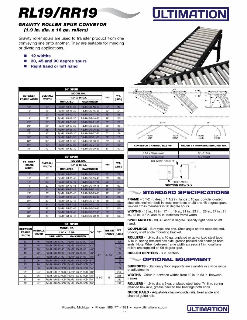
CONVEYOR CHANNEL SIZE "H" ORDER BY MOUNTING BRACKET NO.
3 1/2 x 10 ga. steel ATL-11745
6 1/2 x 12 ga. steel ATL-13082
Gravity roller spurs are used to transfer product from one conveying line onto another. They are suitable for merging or diverging applications.
n 12 widths n 30, 45 and 90 degree spurs n Right hand or left hand
STANDARD SPECIFICATIONSFRAME - 3 1/2 in. deep x 1 1/2 in. flange x 10 ga. powder coated steel channel with bolt-in cross members on 30 and 45 degree spurs; welded cross members in 90 degree spurs
WIDTHS - 13 in., 15 in., 17 in., 19 in., 21 in., 23 in., 25 in., 27 in., 31 in., 33 in., 37 in. and 39 in. between frame width
SPUR ANGLES - 30, 45 and 90 degree. Specify right hand or left hand.
COUPLINGS - Butt type one end. Shelf angle on the opposite end. Specify shelf angle mounting bracket.
ROLLERS - 1.9 in. dia. x 16 ga. unplated or galvanized steel tube, 7/16 in. spring retained hex axle, grease packed ball bearings both ends. Note: When between frame width exceeds 21 in., dual lane rollers are supplied on 90 degree spur.
ROLLER CENTERS - 3 in. centers
OPTIONAL EQUIPMENTSUPPORTS - Stationary floor supports are available in a wide range of adjustments
WIDTHS - Other in-between widths from 10 in. to 63 in. between frames
ROLLERS - 1.9 in. dia. x 9 ga. unplated steel tube, 7/16 in. spring retained hex axle, grease packed ball bearings both ends
GUIDE RAILS - Adjustable channel guide rails, fixed angle and channel guide rails
SECTION VIEW X-X
H
MOUNTING BRACKET
SHELF ANGLE
RL19/RR19
30° SPUR
BETWEENFRAME WIDTH
OVERALLWIDTH
MODEL NO.
"A"WT.
(LBS.)1.9" X 16 GA.
UNPLATED GALVANIZED
13" 16" R(L/R)19U-13-30 R(L/R)19G-13-30 37" 113
15" 18" R(L/R)19U-15-30 R(L/R)19G-15-30 39" 121
17" 20" R(L/R)19U-17-30 R(L/R)19G-17-30 45" 128
19" 22" R(L/R)19U-19-30 R(L/R)19G-19-30 48" 135
21" 24" R(L/R)19U-21-30 R(L/R)19G-21-30 51" 137
23" 26" R(L/R)19U-23-30 R(L/R)19G-23-30 56" 143
25" 28" R(L/R)19U-25-30 R(L/R)19G-25-30 60" 150
27" 30" R(L/R)19U-27-30 R(L/R)19G-27-30 63" 156
31" 34" R(L/R)19U-31-30 R(L/R)19G-31-30 72" 159
33" 36" R(L/R)19U-33-30 R(L/R)19G-33-30 75" 162
37" 40" R(L/R)19U-37-30 R(L/R)19G-37-30 84" 169
39" 42" R(L/R)19U-39-30 R(L/R)19G-39-30 87" 172
GRAVITY ROLLER SPUR CONVEYOR (1.9 in. dia. x 16 ga. rollers)
45° SPUR
BETWEENFRAMEWIDTH
OVERALLWIDTH
MODEL NO.
"A"WT.
(LBS.)1.9" X 16 GA.
UNPLATED GALVANIZED
13" 16" R(L/R)19U-13-45 R(L/R)19G-13-45 27" 108
15" 18" R(L/R)19U-15-45 R(L/R)19G-15-45 30" 116
17" 20" R(L/R)19U-17-45 R(L/R)19G-17-45 33" 124
19" 22" R(L/R)19U-19-45 R(L/R)19G-19-45 36" 132
21" 24" R(L/R)19U-21-45 R(L/R)19G-21-45 39" 140
23" 26" R(L/R)19U-23-45 R(L/R)19G-23-45 42" 147
25" 28" R(L/R)19U-25-45 R(L/R)19G-25-45 45" 156
27" 30" R(L/R)19U-27-45 R(L/R)19G-27-45 48" 163
31" 34" R(L/R)19U-31-45 R(L/R)19G-31-45 54" 170
33" 36" R(L/R)19U-33-45 R(L/R)19G-33-45 57" 175
37" 40" R(L/R)19U-37-45 R(L/R)19G-37-45 63" 185
39" 42" R(L/R)19U-39-45 R(L/R)19G-39-45 66" 193
90° SPUR
BETWEENFRAMEWIDTH
OVERALLWIDTH
MODEL NO.
"A" "B"INSIDE RADIUS
WT.
(LBS.)1.9" X 16 GA.
UNPLATED GALVANIZED
13" 16" R(L/R)19U-13-90 R(L/R)19G-13-90 42"
33" 32 1/2"
92
15" 18" R(L/R)19U-15-90 R(L/R)19G-15-90 42" 100
17" 20" R(L/R)19U-17-90 R(L/R)19G-17-90 48" 109
19" 22" R(L/R)19U-19-90 R(L/R)19G-19-90 48" 117
21" 24" R(L/R)19U-21-90 R(L/R)19G-21-90 48" 126
23" 26" R(L/R)19U-23-90D R(L/R)19G-23-90D 54" 156
25" 28" R(L/R)19U-25-90D R(L/R)19G-25-90D 54" 164
27" 30" R(L/R)19U-27-90D R(L/R)19G-27-90D 54" 172
31" 34" R(L/R)19U-31-90D R(L/R)19G-31-90D 68"
48 1/2" 48"
206
33" 36" R(L/R)19U-33-90D R(L/R)19G-33-90D 78" 215
37" 40" R(L/R)19U-37-90D R(L/R)19G-37-90D 78" 233
39" 42" R(L/R)19U-39-90D R(L/R)19G-39-90D 78" 242
30°/45° 90°
RIGHT HAND
LEFT HAND
RIGHT HAND
LEFT HAND
"R""B"
"A"
60"81"
45°30°
90°
"A" "A"
x
x

68Roseville, Michigan • Phone: (586) 771-1881 • www.ultimationinc.com
The RS25 gravity roller conveyor is ideal for conveying medium or heavy weight packages. They are useful for assembly, warehousing, or shipping applications.
BETWEENFRAMEWIDTH
OVERALLWIDTH
MODEL NO.ROLLER
CENTERSWT. (LBS.)
2.5" X 11 GA.UNPLATED 5' 10'
13" 16 1/4"
RS25U-13-3 3" 185 364
RS25U-13-4 4" 155 303
RS25U-13-6 6" 125 242
15" 18 1/4"
RS25U-15-3 3" 200 390
RS25U-15-4 4" 170 330
RS25U-15-6 6" 135 260
17" 20 1/4"
RS25U-17-3 3" 215 420
RS25U-17-4 4" 180 350
RS25U-17-6 6" 145 280
19" 22 1/4"
RS25U-19-3 3" 234 458
RS25U-19-4 4" 192 375
RS25U-19-6 6" 151 292
21" 24 1/4"
RS25U-21-3 3" 245 480
RS25U-21-4 4" 200 390
RS25U-21-6 6" 160 310
23" 26 1/4"
RS25U-23-3 3" 260 510
RS25U-23-4 4" 210 410
RS25U-23-6 6" 165 320
25" 28 1/4"
RS25U-25-3 3" 282 552
RS25U-25-4 4" 230 447
RS25U-25-6 6" 177 342
27" 30 1/4"
RS25U-27-3 3" 297 594
RS25U-27-4 4" 235 460
RS25U-27-6 6" 180 350
31" 34 1/4"
RS25U-31-3 3" 312 636
RS25U-31-4 4" 267 519
RS25U-31-6 6" 203 391
33" 36 1/4"
RS25U-33-3 3" 345 678
RS25U-33-4 4" 265 520
RS25U-33-6 6" 200 390
37" 40 1/4"
RS25U-37-3 3" 355 700
RS25U-37-4 4" 285 560
RS25U-37-6 6" 215 420
39" 42 1/4"
RS25U-39-3 3" 375 740
RS25U-39-4 4" 285 580
RS25U-39-6 6" 220 430
43" 46 1/4"
RS25U-43-3 3" 415 820
RS25U-43-4 4" 305 620
RS25U-43-6 6" 225 450
47" 50 1/4"
RS25U-47-3 3" 455 900
RS25U-47-4 4" 325 660
RS25U-47-6 6" 235 470
51" 54 1/4"
RS25U-51-3 3" 495 980
RS25U-51-4 4" 345 700
RS25U-51-6 6" 245 490
55" 58 1/4"
RS25U-55-3 3" 535 1,060
RS25U-55-4 4" 365 740
RS25U-55-6 6" 255 550
n 3 roller centers
n Powder coated steel frames
STANDARD SPECIFICATIONSFRAME – 4 in. deep x 1 5/8 in. flange x 4 ga. powder coated steel channel with bolt-in cross members. Roller set high.
WIDTHS – 13 in., 15 in., 17 in., 19 in., 21 in., 23 in., 25 in., 27 in., 31 in., 33 in., 37 in., 39 in., 43 in., 47 in., 51 in. and 55 in. between frames
LENGTH—5 ft. and 10 ft. standard
COUPLINGS – Butt type for bolting sections together
ROLLERS – 2 1/2 in. x 11 ga. unplated steel tube, 11/16 in. spring hex retained axle, grease packed ball bearings both ends.
ROLLER CENTERS – 3 in., 4 in. or 6 in. centers
OPTIONAL EQUIPMENTSUPPORTS– Floor supports are available in a wide range of adjustments
LENGTHS - Other lengths from 2 ft. to 10 ft.
WIDTHS – Other in-between widths from 7 in. to 67 in. between frames
ROLLERS SET LOW - Rollers set 3/4 in. low in 4 in. deep x 1 5/8 in. flange x 4 ga. steel channel with welded cross members
STRUCTURAL STEEL FRAMES – 4 in. x 5.4 lb., 5 in. x 6.7 lb. or 6 in. x 8.2 lb. powder coated structural steel channel. Rollers set high only
GUIDE RAILS - Fixed angle guide rails
END STOP – 6 in. x 8.2 lb. structural channel end stop
RS25GRAVITY ROLLER CONVEYOR (2 1/2 in. dia. x 11 ga. rollers)
BETWEEN FRAME WIDTH
OVERALL WIDTH
4"
3/8"
2-1/2" DIA. ROLLER
BETWEEN FRAME WIDTH
OVERALL WIDTH
4"
3/4"
2-1/2" DIA. ROLLER
ROLLERS SET HIGH
ROLLERS SET LOW
FRAME CAPACITY
SUPPORTCENTERS
MAX. DISTRIBUTEDLIVE LOAD
PER FOOT (LBS.)
5' 1620
10' 288
ROLLER CAPACITY
BETWEEN FRAMES
MAX. STATIC LOAD PER ROLLER (LBS.)
13"-41" 700
43"-55" 485
57"-67" 345

69Roseville, Michigan • Phone: (586) 771-1881 • www.ultimationinc.com
Gravity roller curves are compatible with straight section providing flexibility to your conveyor line. Curves will convey product with a minimum amount of pitch based on weight and size.
n 15 widths n Powder coated steel frames n 30, 45, 60 and 90 degree curves
STANDARD SPECIFICATIONSFRAME – 4 in. deep x 1 5/8 in. flange x 4 ga. powder coated steel channel with bolt-in cross members. Roller set high.
WIDTHS – 13 in., 15 in., 17 in., 19 in., 21 in., 23 in., 25 in., 27 in., 31 in., 33 in., 37 in., 39 in., 43 in., 47 in. and 51 in. between frames
CURVES – 30, 45, 60 and 90 degree curves. 32 1/2 in. or 48 in. inside radius dependent upon between width.
COUPLINGS – Butt type for bolting sections together
ROLLERS – 2 1/2 in. x 11 ga. unplated steel tube, 11/16 in. spring hex retained axle, grease packed ball bearings both ends
SUPPORTS - Floor supports are available in a wide range of adjust-ments
SPECIAL DEGREE CURVES - Contact factory
WIDTHS - Other in-between widths from 10 in. to 51 in. between frames
ROLLERS SET LOW - Rollers set 3/4 in. low in 4 in. deep x 1 5/8 in. flange x 4 ga. powdered coated steel channel with welded cross members
FRAMES – 4 in. x 5.4 lb. powder coated structural steel channel
GUIDE RAILS – Fixed angle guide rails
INSIDE RADIUS
RC25GRAVITY ROLLER CURVE CONVEYOR (2 1/2 in. dia. x 11 ga. rollers)
30° CURVE
BETWEENFRAMEWIDTH
OVERALLWIDTH
MODEL NO.INSIDERADIUS
ROLLERSPER
CURVEWT. (LBS.)2.5" X 11 GA.
UNPLATED
13" 16 1/4" RC25U-13-30
32 1/2"5
Single
5715" 18 1/4" RC25U-15-30 6117" 20 1/4" RC25U-17-30 6619" 22 1/4" RC25U-19-30 7021" 24 1/4" RC25U-21-30 7523" 26 1/4" RC25U-23-30 8125" 28 1/4" RC25U-25-30 8627" 30 1/4" RC25U-27-30 9131" 34 1/4" RC25U-31-30D
48"13
Double
14333" 36 1/4" RC25U-33-30D 14837" 40 1/4" RC25U-37-30D 16139" 42 1/4" RC25U-39-30D 16743" 46 1/4" RC25U-43-30D 18147" 50 1/4" RC25U-47-30D 19251" 54 1/4" RC25U-51-30D 205
60° CURVE
BETWEENFRAMEWIDTH
OVERALLWIDTH
MODEL NO.INSIDERADIUS
ROLLERSPER
CURVEWT. (LBS.)2.5" X 11 GA.
UNPLATED
13" 16 1/4" RC25U-13-60
32 1/2"10
Single
12815" 18 1/4" RC25U-15-60 13817" 20 1/4" RC25U-17-60 15019" 22 1/4" RC25U-25-60 15921" 24 1/4" RC25U-21-60 17323" 26 1/4" RC25U-23-60 18325" 28 1/4" RC25U-25-60 19527" 30 1/4" RC25U-27-60 20731" 34 1/4" RC25U-31-60D
48"23
Double
32433" 36 1/4" RC25U-33-60D 33937" 40 1/4" RC25U-37-60D 36639" 42 1/4" RC25U-39-60D 38143" 46 1/4" RC25U-43-60D 41047" 50 1/4" RC25U-47-60D 43851" 54 1/4" RC25U-51-60D 467
BETWEEN FRAME WIDTH
OVERALL WIDTH
4"
1/4"
2-1/2" DIA. ROLLER
1-1/2"
4"
3/4"
2-1/2" DIA. ROLLERROLLERS SET HIGH ROLLERS SET LOW
BETWEEN FRAME WIDTH
OVERALL WIDTH
OUTSIDE RADIUS
45° CURVE
BETWEENFRAMEWIDTH
OVERALLWIDTH
MODEL NO.INSIDERADIUS
ROLLERSPER
CURVEWT. (LBS.)2.5" X 11 GA.
UNPLATED
13" 16 1/4" RC25U-13-45
32 1/2"8
Single
9115" 18 1/4" RC25U-15-45 9817" 20 1/4" RC25U-17-45 10619" 22 1/4" RC25U-19-45 11321" 24 1/4" RC25U-21-45 12123" 26 1/4" RC25U-23-45 12825" 28 1/4" RC25U-25-45 13627" 30 1/4" RC25U-27-45 14331" 34 1/4" RC25U-31-45D
48"19
Double
31133" 36 1/4" RC25U-33-45D 32337" 40 1/4" RC25U-37-45D 34839" 42 1/4" RC25U-39-45D 36043" 46 1/4" RC25U-43-45D 38547" 50 1/4" RC25U-47-45D 40851" 54 1/4" RC25U-51-45D 434
90° CURVE
BETWEENFRAMEWIDTH
OVERALLWIDTH
MODEL NO.INSIDERADIUS
ROLLERSPER
CURVEWT. (LBS.)2.5" X 11 GA.
UNPLATED
13" 16 1/4" RC25U-13-90
32 1/2"16
Single
17015" 18 1/4" RC25U-15-90 18517" 20 1/4" RC25U-17-90 20019" 22 1/4" RC25U-25-90 21221" 24 1/4" RC25U-21-90 23023" 26 1/4" RC25U-23-90 24525" 28 1/4" RC25U-25-90 26027" 30 1/4" RC25U-27-90 27631" 34 1/4" RC25U-31-90D
48"37
Double
43233" 36 1/4" RC25U-33-90D 45137" 40 1/4" RC25U-37-90D 48939" 42 1/4" RC25U-39-90D 50843" 46 1/4" RC25U-43-90D 45647" 50 1/4" RC25U-47-90D 48351" 54 1/4" RC25U-51-90D 622
Note: Dual lane rollers from 31" BF through 51" BF
OPTIONAL EQUIPMENT
70Roseville, Michigan • Phone: (586) 771-1881 • www.ultimationinc.com
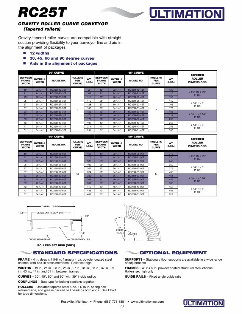
Gravity tapered roller curves are compatible with straight section providing flexibility to your conveyor line and aid in the alignment of packages.
n 12 widths n 30, 45, 60 and 90 degree curves n Aids in the alignment of packages
STANDARD SPECIFICATIONSFRAME – 4 in. deep x 1 5/8 in. flange x 4 ga. powder coated steel channel with bolt-in cross members. Roller set high.
WIDTHS – 19 in., 21 in., 23 in., 25 in., 27 in., 31 in., 33 in., 37 in., 39 in., 43 in., 47 in. and 51 in. between frames
CURVES – 30°, 45°, 60° and 90° with 39" inside radius
COUPLINGS – Butt type for bolting sections together
ROLLERS – Unplated tapered steel tube, 11/16 in. spring hex retained axle, and grease packed ball bearings both ends. See Chart for tube dimensions.
OPTIONAL EQUIPMENTSUPPORTS – Stationary floor supports are available in a wide range of adjustments
FRAMES – 4" x 4.5 lb. powder coated structural steel channel. Rollers set high only
GUIDE RAILS – Fixed angle guide rails
RC25TGRAVITY ROLLER CURVE CONVEYOR (Tapered rollers)
30° CURVE 45° CURVETAPERED ROLLER
DIMENSIONS
BETWEENFRAMEWIDTH
OVERALLWIDTH
MODEL NO.ROLLERS
PERCURVE
WT. (LBS.)
BETWEENFRAMEWIDTH
OVERALLWIDTH
MODEL NO.ROLLERS
PERCURVE
WT. (LBS.)
19" 22 1/4" RC25U-19-30T
5
93 19" 22 1/4" RC25U-19-45T
7
1222 1/2" TO 3 1/2"
11 Ga.21" 24 1/4" RC25U-21-30T 102 21" 24 1/4" RC25U-21-45T 126
23" 26 1/4" RC25U-23-30T 110 23" 26 1/4" RC25U-23-45T 155
25" 28 1/4" RC25U-25-30T 119 25" 28 1/4" RC25U-25-45T 140 2 1/2" TO 4"
11 GA.27" 30 1/4" RC25U-27-30T 128 27" 30 1/4" RC25U-27-45T 162
31" 34 1/4" RC25U-31-30T 145 31" 34 1/4" RC25U-31-45T 173
33" 36 1/4" RC25U-33-30T 153 33" 36 1/4" RC25U-33-45T 183 2 1/2" TO 4 1/2"
11 GA.37" 40 1/4" RC25U-37-30T 171 37" 40 1/4" RC25U-37-45T 219
39" 42 1/4" RC25U-39-30T 179 39" 42 1/4" RC25U-39-45T 233
43" 46 1/4" RC25U-43-30T 197 43" 46 1/4" RC25U-43-45T 258 2 1/2" TO 5"
11 GA.47" 50 1/4" RC25U-47-30T 214 47" 50 1/4" RC25U-47-45T 282
51" 54 1/4" RC25U-51-30T 231 51" 54 1/4" RC25U-51-45T 306
ROLLERS SET HIGH (ONLY)
60° CURVE 90° CURVETAPERED ROLLER
DIMENSIONS
BETWEENFRAMEWIDTH
OVERALLWIDTH
MODEL NO.ROLLERS
PERCURVE
WT. (LBS.)
BETWEENFRAMEWIDTH
OVERALLWIDTH
MODEL NO.ROLLERS
PERCURVE
WT. (LBS.)
19" 22 1/4" RC25U-25-60T
10
159 19" 22 1/4" RC25U-25-90T
14
2122 1/2" TO 3 1/2"
11 Ga.21" 24 1/4" RC25U-21-60T 173 21" 24 1/4" RC25U-21-90T 230
23" 26 1/4" RC25U-23-60T 183 23" 26 1/4" RC25U-23-90T 245
25" 28 1/4" RC25U-25-60T 195 25" 28 1/4" RC25U-25-90T 260 2 1/2" TO 4"
11 GA.27" 30 1/4" RC25U-27-60T 207 27" 30 1/4" RC25U-27-90T 276
31" 34 1/4" RC25U-31-60T 324 31" 34 1/4" RC25U-31-90T 432
33" 36 1/4" RC25U-33-60T 339 33" 36 1/4" RC25U-33-90T 451 2 1/2" TO 4 1/2"
11 GA.37" 40 1/4" RC25U-37-60T 366 37" 40 1/4" RC25U-37-90T 489
39" 42 1/4" RC25U-39-60T 381 39" 42 1/4" RC25U-39-90T 508
43" 46 1/4" RC25U-43-60T 410 43" 46 1/4" RC25U-43-90T 456 2 1/2" TO 5"
11 GA.47" 50 1/4" RC25U-47-60T 438 47" 50 1/4" RC25U-47-90T 483
51" 54 1/4" RC25U-51-60T 467 51" 54 1/4" RC25U-51-90T 622
39"INSIDERADIUS DEGREE

71Roseville, Michigan • Phone: (586) 771-1881 • www.ultimationinc.com
90°
"C" "B" "A"
60"
81" "R"
"D"
45° 30° X
X
CONVEYOR CHANNEL SIZE "H" ORDER BY MOUNTING BRACKET NO.
4" x 4 ga. steel ATL-13609
Gravity roller spurs are used to transfer product from one conveying line onto another. They are suitable for merging or diverging applications.
n 15 widths n 30, 45 and 90 degree spurs n Right hand or left hand
STANDARD SPECIFICATIONSFRAME – 4 in. deep x 1 5/8 in. flange x 4 ga. powder coated steel channel with bolt-in cross members. Rollers set high.
WIDTHS – 13 in., 15 in., 17 in., 19 in., 21 in., 23 in., 25 in., 27 in., 31 in., 33 in., 37 in., 39 in., 43 in., 47 in. and 51 in. between frames
SPUR ANGLES – 30, 45 and 90 degree spurs. Specify right hand or left hand.
COUPLINGS – Butt type one end. Shelf angle on the opposed end. Specify shelf angle mounting bracket.
ROLLERS – 2 1/2 in. x 11 ga. unplated steel tube, 11/16 in. spring hex retained axle, grease packed ball bearings both ends
ROLLER CENTERS - 3 in. centers
OPTIONAL EQUIPMENTSUPPORTS - Floor supports are available in a wide range of adjustments
WIDTHS - Other in-between widths from 10 in. to 51 in. between frames
FRAMES – 4" x 4.5 lb. powder coated structural steel channel. Rollers set high only.
GUIDE RAILS – Fixed angle guide rails
RL25/RR25
30° SPUR
BETWEENFRAME WIDTH
OVERALLWIDTH
MODEL NO.
"A" WT. (LBS.)2.5" X 11 GA.UNPLATED
13" 16-1/4" R(L/R)25U-13-30 39" 28415" 18-1/4" R(L/R)25U-15-30
54"
30217" 20-1/4" R(L/R)25U-17-30 32019" 22-1/4" R(L/R)25U-19-30 33821" 24-1/4" R(L/R)25U-21-30 35523" 26-1/4" R(L/R)25U-23-30
77"
37425" 28-1/4" R(L/R)25U-25-30 38927" 30-1/4" R(L/R)25U-27-30 40331" 34-1/4" R(L/R)25U-31-30 43633" 36-1/4" R(L/R)25U-33-30
96"445
37" 40-1/4" R(L/R)25U-37-30 46639" 42-1/4" R(L/R)25U-39-30 46543" 46-1/4" R(L/R)25U-43-30
114"477
47" 50-1/4" R(L/R)25U-47-30 48451" 54-1/4" R(L/R)25U-51-30 503
GRAVITY ROLLER SPUR CONVEYOR (2 1/2 in. dia. x 11 ga. rollers)
90° SPUR
BETWEENFRAMEWIDTH
OVERALLWIDTH
MODEL NO.
"C" "D"INSIDE RADIUS
"R"WT. (LBS.)2.5" X 11 GA.
UNPLATED
13" 16-1/4" R(L/R)25U-13-90
39"
33" 32 1/2"
133
15" 18-1/4" R(L/R)25U-15-90 139
17" 20-1/4" R(L/R)25U-17-90 152
19" 22-1/4" R(L/R)25U-19-90 158
21" 24-1/4" R(L/R)25U-21-90
54"
164
23" 26-1/4" R(L/R)25U-23-90 170
25" 28-1/4" R(L/R)25U-25-90 175
27" 30-1/4" R(L/R)25U-27-90 180
31" 34-1/4" R(L/R)25U-31-90
77"
48 1/2" 48"
263
33" 36-1/4" R(L/R)25U-33-90 267
37" 40-1/4" R(L/R)25U-37-90 281
39" 42-1/4" R(L/R)25U-39-90 295
43" 46-1/4" R(L/R)25U-43-90 307
47" 50-1/4" R(L/R)25U-47-9096"
315
51" 54-1/4" R(L/R)25U-51-90 326
45° SPUR
BETWEENFRAME WIDTH
OVERALLWIDTH
MODEL NO.
"B" WT. (LBS.)2.5" X 11 GA.UNPLATED
13" 16-1/4" R(L/R)25U-13-45
39"
28215" 18-1/4" R(L/R)25U-15-45 31917" 20-1/4" R(L/R)25U-17-45 32319" 22-1/4" R(L/R)25U-19-45 35421" 24-1/4" R(L/R)25U-21-45
54"
38023" 26-1/4" R(L/R)25U-23-45 38825" 28-1/4" R(L/R)25U-25-45 41727" 30-1/4" R(L/R)25U-27-45 43331" 34-1/4" R(L/R)25U-31-45
77"
47233" 36-1/4" R(L/R)25U-33-45 48337" 40-1/4" R(L/R)25U-37-45 52739" 42-1/4" R(L/R)25U-39-45 53143" 46-1/4" R(L/R)25U-43-45 57747" 50-1/4" R(L/R)25U-47-45
96"559
51" 54-1/4" R(L/R)25U-51-45 568
30°/45°
RIGHT HAND
LEFTHAND
RIGHT HAND
LEFTHAND
90°
SECTION VIEW X-X
H
MOUNTING BRACKET
SHELF ANGLE
Specification Sheet – 09/16/15 R1

72Roseville, Michigan • Phone: (586) 771-1881 • www.ultimationinc.com
The RS35 gravity roller conveyor is ideal for conveying heavy loads. They are useful for assembly, warehousing, or shipping applications.
BETWEENFRAMEWIDTH
MODEL NO.ROLLER
CENTERSWT. (LBS.)
3.5" X .300 WALLUNPLATED 5' 10'
7"
RS35U-7-4 4" 228 453
RS35U-7-6 6" 177 351
RS35U-7-8 8" 152 300
RS35U-7-12 12" 126 249
11"
RS35U-11-4 4" 300 596
RS35U-11-6 6" 226 449
RS35U-11-8 8" 189 375
RS35U-11-12 12" 153 302
15"
RS35U-15-4 4" 372 740
RS35U-15-6 6" 276 548
RS35U-15-8 8" 227 451
RS35U-15-12 12" 179 355
19"
RS35U-19-4 4" 446 884
RS35U-19-6 6" 325 646
RS35U-19-8 8" 265 527
RS35U-19-12 12" 206 408
23"
RS35U-23-4 4" 515 1,027
RS35U-23-6 6" 375 744
RS35U-23-8 8" 303 602
RS35U-23-12 12" 232 461
27"
RS35U-27-4 4" 587 1,170
RS35U-27-6 6" 423 842
RS35U-27-8 8" 341 678
RS35U-27-12 12" 259 514
31"
RS35U-31-4 4" 659 1,314
RS35U-31-6 6" 472 941
RS35U-31-8 8" 379 754
RS35U-31-12 12" 285 567
35"
RS35U-35-4 4" 728 1,457
RS35U-35-6 6" 521 1,038
RS35U-35-8 8" 416 829
RS35U-35-12 12" 311 619
39"
RS35U-39-4 4" 802 1,600
RS35U-39-6 6" 570 1,136
RS35U-39-8 8" 454 904
RS35U-39-12 12" 338 672
43"
RS35U-43-4 4" 874 1744
RS35U-43-6 6" 619 1235
RS35U-43-8 8" 492 980
RS35U-43-12 12" 365 726
47"
RS35U-47-4 4" 946 1,888
RS35U-47-6 6" 668 1,333
RS35U-47-8 8" 530 1,056
RS35U-47-12 12" 391 779
51"
RS35U-51-4 4" 1,017 2,030
RS35U-51-6 6" 719 1,431
RS35U-51-8 8" 567 1,131
RS35U-51-12 12" 417 831
n 12 widths n 4 roller centers n Powder coated steel frames
STANDARD SPECIFICATIONSFRAME – 5 in. x 6.7 lb. powder coated structural steel channel with welded cross members. Rollers set high
WIDTHS – 7 in., 11 in., 15 in., 19 in., 23 in., 27 in., 31 in., 35 in., 39 in., 43 in., 47 in. and 51 in. between frames
LENGTH – 5 ft. and 10 ft. straight sections
COUPLINGS – Butt type for bolting sections together
ROLLERS – 3 1/2 in. x .300 wall unplated steel tube, 1 1/16 in. hex axle, pin retained, grease packed ball bearings both ends
ROLLER CENTERS – 4 in., 6 in., 8 in. or 12 in. centers
OPTIONAL EQUIPMENTSUPPORTS – Stationary floor supports are available in a wide range of adjustments
LENGTHS – Other lengths from 2 ft. to 10 ft.
WIDTHS – Other in-between widths from 7 in. to 67 in. between frames
ROLLERS SET LOW – Rollers set 3/4 in. low in 5 in. x 6.7 lb. structural steel channel
RS35GRAVITY ROLLER CONVEYOR (3 1/2 in. dia. x .300 rollers)
ROLLERS SET HIGH
ROLLERS SET LOW
SUPPORT CENTERS
FRAME CAPACITY ROLLER CAPACITY
MAX. DISTRIBUTED LIVE LOAD PER FOOT
MAXIMUM LOAD PER ROLLER
5' 16201145
10' 288
3/8"
5"
BETWEEN FRAME WIDTH
COTTER PIN3 1/2" DIA ROLLER
5"
BETWEEN FRAME WIDTH
3/4"
COTTER PIN
3 1/2" DIA ROLLER

73Roseville, Michigan • Phone: (586) 771-1881 • www.ultimationinc.com
Ball transfer tables are ideal where products need to be manually rotated or repositioned at a work station. They are also used when manually transferring products from one conveyor line to another.
n 1 in. ball casters n 4 ball centers n Powder coated steel frames
STANDARD SPECIFICATIONS
FRAME – 2 1/2 in. deep x 1 in. flange x 12 ga. powder coated steel for bolting up to 1 3/8 in. dia. gravity roller conveyor or skatewheel conveyor (specify). 3 1/2 in. deep x 1 1/2 in. flange x 10 ga. powder coated steel for bolting up to 1.9 dia. gravity roller conveyor or other select powered conveyors.
WIDTHS • 2 1/2" frames: 10 in., 13 in., 16 in. and 22 in. between frames
• 3 1/2" frames: 13 in., 15 in., 17 in., 19 in., 21 in., 23 in., 25 in., 27 in., 31 in., 33 in., 37 in. and 39 in. between frames
LENGTHS – 1 ft. through 10 ft. in 1 ft. increments
COUPLINGS – Butt type for bolting sections together
BALL TRANSFERS – 1 in. dia. ball transfers
BALL CENTERS – 2 in., 3 in., 4 in. or 6 in. centers
BTT25/BTT35BALL TRANSFER TABLE
BTT35 (3 1/2 IN. FRAMES)
BETWEEN FRAME WIDTH
OVERALL WIDTH
MODEL NO.WEIGHT
PER FOOT
13" 16"
BTT35-13-2 25.86
BTT35-13-3 18.06
BTT35-13-4 15.33
BTT35-13-6 -
15" 18"
BTT35-15-2 29.15
BTT35-15-3 20.57
BTT35-15-4 17.45
BTT35-15-6 -
17" 20"
BTT35-17-2 32.45
BTT35-17-3 21.53
BTT35-17-4 18.41
BTT35-17-6 16.07
19" 22"
BTT35-19-2 35.72
BTT35-19-3 23.99
BTT35-19-4 20.48
BTT35-19-6 16.97
21" 24"
BTT35-21-2 39.28
BTT35-21-3 25.50
BTT35-21-4 21.43
BTT35-21-6 18.70
23" 26"
BTT35-23-2 42.27
BTT35-23-3 27.45
BTT35-23-4 23.55
BTT35-23-6 19.66
25" 28"
BTT35-25-2 45.52
BTT35-25-3 29.92
BTT35-25-4 24.45
BTT35-25-6 20.56
27" 30"
BTT35-27-2 48.81
BTT35-27-3 32.43
BTT35-27-4 26.58
BTT35-27-6 22.90
31" 34"
BTT35-31-2 55.35
BTT35-31-3 35.85
BTT35-31-4 29.61
BTT35-31-6 24.15
33" 36"
BTT35-33-2 58.65
BTT35-33-3 38.37
BTT35-33-4 30.57
BTT35-33-6 25.86
37" 40"
BTT35-37-2 65.19
BTT35-37-3 41.79
BTT35-37-4 33.60
BTT35-37-6 27.75
39" 42"
BTT35-39-2 68.48
BTT35-39-3 44.30
BTT35-39-4 35.72
BTT35-39-6 29.48
BTT25 (2 1/2 IN. FRAMES)
BETWEEN FRAME WIDTH
OVERALL WIDTH
MODEL NO.WEIGHT
PER FOOT
10" 12"
BTT25-12-2 19.77
BTT25-12-3 15.09
BTT25-12-4 12.75
BTT25-12-6 -
13" 15"
BTT25-13-2 25.86
BTT25-13-3 18.06
BTT25-13-4 15.33
BTT25-13-6 -
16" 18"
BTT25-16-2 29.60
BTT25-16-3 21.02
BTT25-16-4 17.90
BTT25-16-6 15.56
22" 24"
BTT25-22-2 42.27
BTT25-22-3 27.45
BTT25-22-4 23.55
BTT25-22-6 19.66
LOAD CAPACITY (LBS.)
FRAME SIZE SUPPORT CENTERS
MAXIMUM DISTRIBUTED
LIVE LOAD PER FOOT
MAX. STATIC LOAD
PER BALL
2 1/2" X 1" X 12 ga.5' 270
6510' 38
3 1/2" x 1 1/2" x 10 ga.5' 620
10' 135
3/8" FOR SKATEWHEEL3/32" FOR 1-3/8" GRAVITY ROLLER
OPTIONAL EQUIPMENTSUPPORTS – Stationary floor supports are available in a wide range of adjustments
GUIDE RAILS – Adjustable channel guide rails, fixed angle and channel guide rails
LESS FRAME – Pans with ball transfers only
Specification Sheet – 05/22/15 - R3
1.837
2.40
1.531

74Roseville, Michigan • Phone: (586) 771-1881 • www.ultimationinc.com
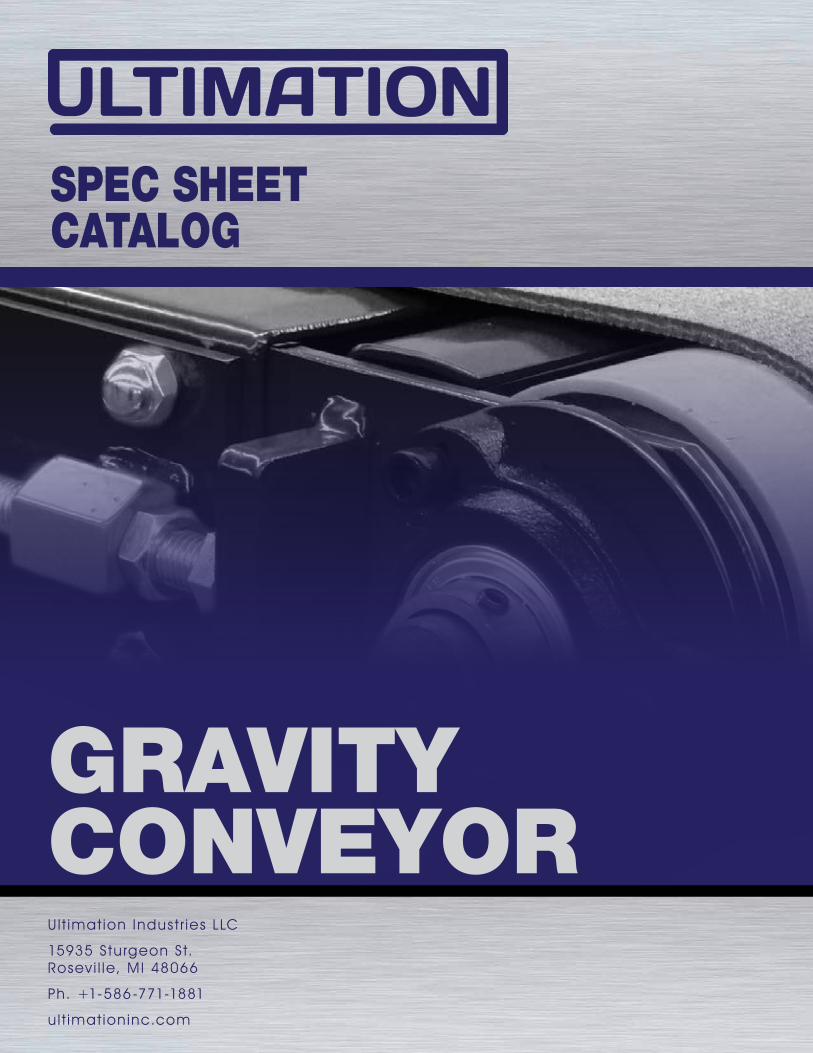
Conveyor rails utilize standard skatewheels mounted to various frame configurations. They are ideal for gravity storage flow racks.
CRCONVEYOR RAILS
CONVEYOR RAIL LOAD CAPACITY
SUPPORT CENTERS
MAXIMUM LOAD PER FOOT (LBS.)
TYPE 1 TYPE 2 TYPE 3S TYPE 3P TYPE 4 TYPE 5
3' 260 223 260 260 260 260
4' 260 92 233 233 260 210
5' 146 50 125 125 198 113
6' 83 28 71 71 112 64
7' 51 17 44 44 69 40
8' 35 12 38 38 49 27
10' 18 6 15 15 24 14
Wheel capacity = 65 lbs. each
2-1/2"
1"
2 7/8"
3"
2"
1"
2-3/8"
2-3/16"
2"
1-3/4"
3-3/4"
1" 1"
6"
3"
3"3 3/4"
2-3/16"
1" 1"
2"
1-3/4"
n 5 frame configurations
n 12 ga. powder coated steel frames
n Ideal for gravity storage flow racks
TYPE 4 – Rail weight: 3.5 lbs./ft.
TYPE 1 – Rail weight: 2.5 lbs./ft.
TYPE 2 – Rail weight: 2.1 lbs./ft.
TYPE 3S (Wheels staggered) – Rail weight: 3.5 lbs./ft.
TYPE 3P (Wheels paired) – Rail weight: 4.2 lbs./ft.
TYPE 5 – Rail weight: 3.0 lbs./ft.