Gravitational Reference Sensor: progress for LTP and LISA
44
Gravitational Reference Sensor: progress for LTP and LISA Rita Dolesi Università degli studi di Trento
Transcript of Gravitational Reference Sensor: progress for LTP and LISA

Gravitational Reference Sensor: progress for LTP and LISA
Rita DolesiUniversità degli studi di Trento

OUTLINE
Introduction
GRS IMPLEMENTATION
Engineering Model for LTP: fabrication status
Back-up/upgrading alternativesInvestigation ongoing in Trento
GRS ON GROUND TESTING
Verification of the noise model:status and prospective
On ground test facilities

Performances of a single axis
“drag free” control loop
The residual acceleration of the test mass will be
noisex
2parasiticmw
fb2Mw
mass S / CX -
extF
Requirements for max PSD of Fext, fparasitic/m, xnoise and for wint and wfb
parasiticf
mf
MFxa parasitic
fbCS
extnoiseparasiticresidual
2/
2
ww
S/C displacement wrt to test mass
Contribution from: S/C, LTP, Gravitational Sensor (CM, CMS, GSC)

Requirements of GRS for LISA
mf
MFxa parasitic
fbCS
extnoiseparasiticresidual
2/
2
ww
Force noise
Stiffness
Displacement noise

Noise Model as Design driver for the GRS
Identifies main sources of displacement noise
force noisestiffness
Several required functionalities are also design driver
and introduce additional noise sources
Measurement and Management of the TM chargeActuation of some TM DOF (LTPand LISA are different)
Caging mechanism of the TM upon launch
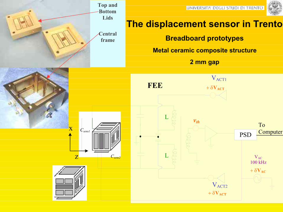
Design of position sensor bread-board prototypes Design of the Engineering Model for LTP
VACT2
Csens1
Csens2
VACT
VACT
vth
PSD
L
L
x
FEEE
VAC 100 kHz VAC
z
To Computer
VACT1
Top and Bottom
Lids
Central frame
The displacement sensor in TrentoBreadboard prototypes
Metal ceramic composite structure
2 mm gap

Baseline Electrode ConfigurationX face
y
z
Y face
x
z
Z face
x
y
• All gap sensing, with relatively large gaps
• Injection on two axes
• 46 mm test mass
• Space for caging, split injection electrodes
4 mm along x, 4 mm injection Baseline: YZ-Injection 2.9 y, 3.5 z
Reducing off-axis stiffness to reduce force cross talking
~ 2 kilosSensor properties improve with size and mass
1-2 mm buffer between plunger / indentation and injection electrodes
Engineering model prototype for LTP
Gap sensing4 mm gaps
Molibdenum+SHAPAL (sapphire)

• GRAVITATIONAL SENSOR CORE (CGS)– A free floating cubic, 27% Pt-73% Gold TM,2 kg– 6-DOF capacitive motion sensor– An electric field based TM actuation system
• VACUUM ENCLOSURE (CGS)
• CHARGE MANAGEMENT SYSTEM (ICL):– TM charge management control– UV light, photo electron extraction based,
• CAGING MECHANISM (RAL)– cages the mass via the action of a plunger that pushes it against end-stops – prevents both translation and rotation– allows multiple operation including re-caging– releases the TM form the centre of the housing
• FEE: sensing and actuation
Engineering Model for LTP
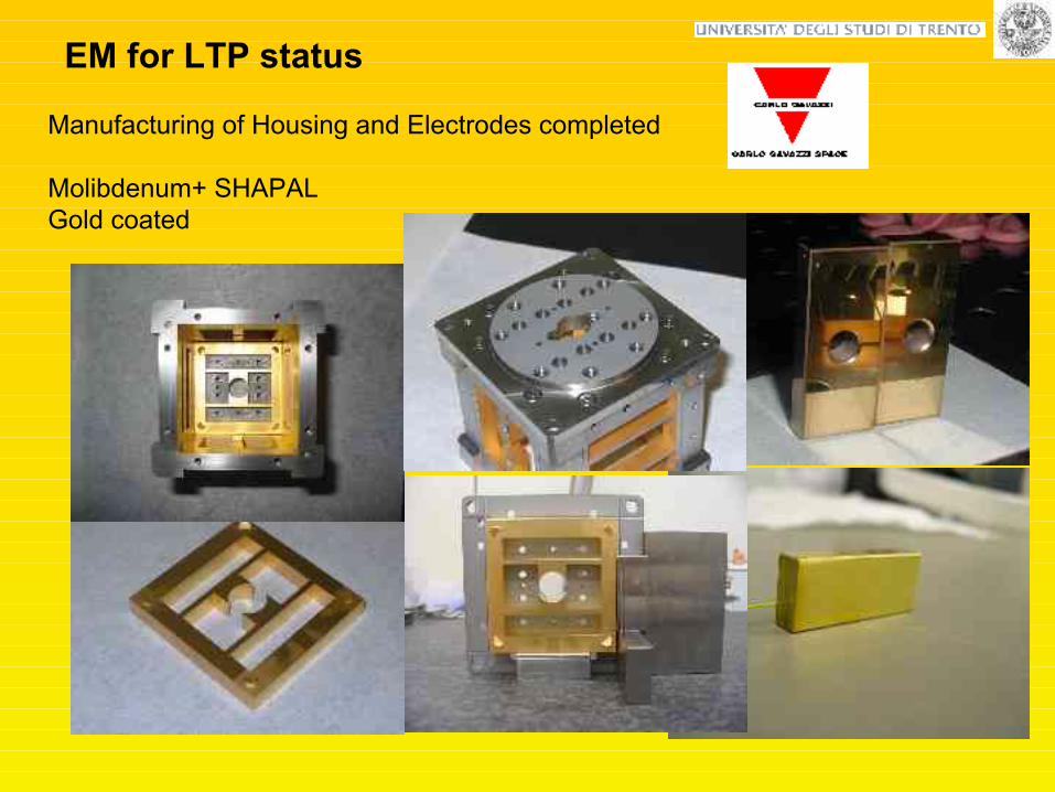
Manufacturing of Housing and Electrodes completed
Molibdenum+ SHAPALGold coated
EM for LTP status

Assembly of the EH on going
EM for LTP status

Test Mass: machining and characterisation completed
EM for LTP status

Talk of Sam Tobin
EM for LTP statusCaging Mechanism

UVLA Testing: funct/perf. testing completed
EMC testing on-going
EM for LTP status

FEE EM: unit tested june03 Testing at UTN TP facility
is underway
EM for LTP status

EM for LTP status
Vacuum Enclosure: integration and testing
on going
Testing Started at S/S level:
Intermediate vibration tests

GRS EM for LTP TestingEnvironmentalFunctionalities….
Noise model verificationOf the EM
GRS Flight Model for LTP
GRS for LISA
LISA PathfinderLTP+ DRS
Upgraded/backup solutions are developed in parallel
EM for LTP FM for LTP LISA
2005
2008
Gravitational compensationMichele Armano
talk

OPTICAL WINDOW alternative design: indium sealing/ glued
Gerhard Heinzel talk
By P. Bosetti, Matteo Benedetti, Vigilio Fontanari

ELECTRODES ALTERNATIVE DESIGN
SAPPHIRE
no brazing
By I. Cristofolini and P. Bosetti

Implementation of the capacitive sensor with an optical read-out
Risk reductionHigher sensitivities ,reduced cross talk
Talk of Luciano Di Fiore
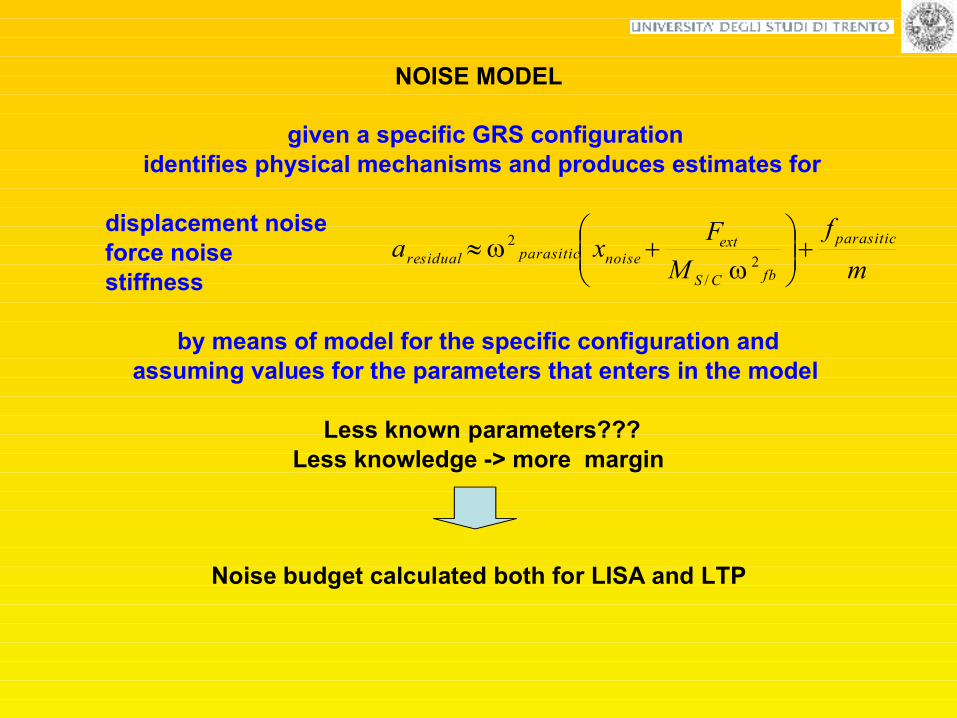
NOISE MODEL
given a specific GRS configuration identifies physical mechanisms and produces estimates for
displacement noiseforce noisestiffness
by means of model for the specific configuration and assuming values for the parameters that enters in the model
Less known parameters???Less knowledge -> more margin
Noise budget calculated both for LISA and LTP
mf
MFxa parasitic
fbCS
extnoiseparasiticresidual
2/
2
ww

Noise source Value (m/s^2/vHz) Noise source Value (m/s^2/vHz)
Thermal effects 5,1E-15 Thermal effects 4.20E-16Brownian noise 1E-15 Brownian noise 1.20E-15Cross-Talk, M3, TM1 2,7E-15 Cross-Talk 6.40E-16Cross-Talk, M3, TM2 4,7E-15Magnetics S/C 1,5E-14 Magnetics S/C 6.00E-16Magnetics, Interplanetary 4,3E-15 Magnetics, Interplanetary 6.90E-17Random charging 2,6E-15 Random charging 9.40E-16Various 4,3E-15 Various 1.00E-15Actuation 5,2E-15Total 1,8E-14 Total 2.10E-15Margin 2,1E-14 Margin 1.90E-15Requirement 2,8E-14 Requirement 2.80E-15
LTP @ 1e-3 Hz LISA @ 1e-4 Hz
NOISE BUDGET FROM NOISE MODEL OF GRS
for LISALess hostile environment
Lower frequencyNo actuation along sensitive axis

Verification of physical mechanism models and parameters measurement
NOISE MODEL VERIFICATION
Key instrument of this testing effort has been a torsion pendulum bench:
torsion pendulum with a hollow replica of the TM inside the GRScharacterizes disturbances generated inside the GRS core
Sensing electrodes
Test Mass inside
Sensor Housing
Torsion Fiber
Mirror for
Optical Readout
•Place upper limit on force disturbances related with GRS and TM surface properties
(no disturbances related to volume effect)
•Characterization of individual disturbance source
The source is modulated
The torque exerted on the test mass is measuredby coherent demodulation of the pendulum twist angle

Pendulum suspension and axis of rotation
One mass configuration Four mass configuration
separation s
gap d
Sensing electrodes 1 2


Phys
. Rev
. Let
t. 20
03

Trans-twist coupling: understood and (nearly) eliminated
after shield!
before shield!
• inclination dependent trans-twist coupling caused by ~mm size exposed dielectric ~ .5 mm from pendulum axis• effect removed by addition of thin electrostatic shield
Good news ... coupling originated in pendulum mount, not intrinsic to sensor... shielding removed the coupling (and the resulting noise)
Bad news ... any bare dielectric in vicinity of sensor is a disaster! (F ~ 100 nN)

insulator
No effect
Suppressed


Upper limit on sensor force noise contributions4E-4 5E-3 Hz torque noise below 10 fN m/sqrt(Hz)
acceleration noise for a bulk LISA test Mass of the same size 1e-12 m/s^2/sqrt(Hz)
@ 3e-3 mHz -> 4e-13 m/s^2/sqrt(Hz) (factor 10 over the LTP flight test goal)
2×10-1610
8×10-175
5×10-171
4×10-160.1
Resolution (Nm)
(3 hours integration
time)
Frequency of applied
disturbance(mHz)
Coherent torque measurement
CURRENT 1 MASS PENDULUM PERFORMANCES
22/1
)(
)()()(
w
www
F
SSS readNthN
Verify the model by measuringthe “transfer fuction” of that effect
and measure the parameters!!

Stray dc voltage + Random arrival of charge
( ) 1 21 21
1dc5
2o
S m 4 mm eventrate 0.1mHz0.8 10m gap 300 s fs 10 mVHz
V--
w ´
Vdc
Random force acting on the test mass

Vdc
+++++++++++++
+++++++++++++
+++++++++++++
+++++++++++++
Simulating a varying charge on the test-mass ac-torque induced
----------------------
----------------------
+++++++++++++
+++++++++++++
+++++++++++++
+++++++++++++
~
Vcomp.
Vdc may be compensated Vdc+Vcomp.=0

Typical Vdc 30 mV
Compensated to 1 mV
Compensation voltage on electrodes (mV)
Torq
ue o
n te
st-m
ass (
fN m
)

DC Bias measurements: stability28 Hour measurement of residual with VCOMP = 20 mV
2 mV/Hz1/2 measurement limit
DC bias stabilityS1/2 < 2 mV /Hz for f ~ mHz
preliminary

UV light fibre

Charge management: demonstration of charge transportin a representative configuration
• currently using a single UV fiber to illuminate both TM and an x-sensing electrode
• apply DC voltage VBIAS to electrodes to bias charge transport (bipolar)
Charge measurement technique3000 e
Relevant LISA discharge threshold 107 charges

δ=1e-6δ=1e-5Sensing capacitive loss
angleDielectric losses
Brownian noise
Compensated @ mV level
100 mV (LTP)10 mV (LISA)
Stray dc biasRandom charging
@ 295 K<0.3 x radiation pressure
fluctuation effect
(preliminary)
@ 293 K1.4 x radiation pressure
fluctuation effect
Temperature dependent outgassing
Outgassing rate and its activation energy
Thermal effects
Measured(torsion pendulum in
Trento)
Assumed in the noise model
Less known effect/parameter
Noise source type
Coherent measurement technique resultsWith a 2 mm gap breadboard prototype (will be repeated with the EM for LTP)
(Talk of Ludovico Carbone)
Moreover
Measurement of full sensor-test mass coupling at 5 % levelSensing electrostatic stiffness in agreement with finite element calculation

1 mass torsion pendulum is limited:Sensitive to torque rather than translational force
Performances close to the thermal noiseIt has only a single DOF
On going facilities upgrading
Improve representativeness:Testing directly the translational degree of freedom
Facilities with more than one force sensitive degree of freedom
Improve sensitivities: high Q fiber!
Bulk magnetic properties measurements
Additional functionalities: implement the identified actuation scheme
and test the low frequency suspension
Test of in flight TM release

4 mass pendulum: testing directly the translational degree of freedom •Translational force measurements• total translational stiffness search• cross-coupling into
•Upgrading: higher Q
Pendulum suspensionand axis of rotation
separationR
1 2

Facilities with more than one “soft” force sensitive degree of freedomAllows for:
Measuring forces and stiffness simultaneously along different degrees of freedom
More effective in identifying and debugging spurious effects
Allows for testing of actuation cross talk with closed feedback loops: in particular, it allows to measure the residual disturbance
along the sensitive translational axis when we close the control loop along the rotation (because is the control loop that will be used also in LISA)
Allows for measuring the stiffness and cross-stiffness simultaneously along different DOF
Verification of the compatibility of the charge measurement by means of a dithering voltage applied in terms of noise induced in x.
Tradeoff is ongoing to identify otherConfigurations
LISA PF INFN collaborationat LNGS
suspension point close to CM: 3 soft DOF

• Measuring LISA TM magnetic properties (residual moment and susceptibility)• Torsion pendulum technique
( ) ( ) ( )tBtmtN
Holder and mirror for
optical readout
Twist angle
Torsion fiber
Applied B field
Measurement of magnetic moment: ( ) ( )tBVmtm
00
28
0 mA10 -m
510-
Magnetic Testing
• Measurement of susceptility () requires non-zero second derivative of B (in progress)
• Residual moment detection with homogeneous field

LISA Test Mass magnetic moment : full sized TM
At 3 mHz:Hz
rad10 6-S
Assuming integration time: s104T and field T10 4-B
Considering full sized TM:
• L = 46mm, weigh ≈2kg
• ≈230 g Al sample holder
• 110 m W fiber, loaded to ≈65%
• (f 2·10-6 Nm/rad)
• Quality factor Q=1000
• Readout limited noise:
Coil features:
• R = 45 cm
• I 1 A, current in phase on both coils
I2
2R
R
I1running Helmholtz coils to
obtain uniform field
2100 mA102
-
BTS
m f

Importance of on ground testing techniques development
•Verification of GRS performances
• Unique test procedures relevant to precision measurement science
• Techniques will be implemented in flight with LTP
•In principle,the “subtraction tecnique” would allow with the LTP
to detect residual acceleration below the expected limit

Team in Trento
Michele ArmanoMatteo Benedetti
Daniele BortoluzziPaolo Bosetti
Ludovico CarboneAntonella Cavalleri
Ilaria Cristofolini
Mauro Da Lio Rita Dolesi
VigilioFontanari C.D. Hoyle
Mauro Hueller Stefano Vitale
W.J. Weber