Grasping of Unknown Objects from a Table Top
12
HAL Id: inria-00325794 https://hal.inria.fr/inria-00325794 Submitted on 30 Sep 2008 HAL is a multi-disciplinary open access archive for the deposit and dissemination of sci- entific research documents, whether they are pub- lished or not. The documents may come from teaching and research institutions in France or abroad, or from public or private research centers. L’archive ouverte pluridisciplinaire HAL, est destinée au dépôt et à la diffusion de documents scientifiques de niveau recherche, publiés ou non, émanant des établissements d’enseignement et de recherche français ou étrangers, des laboratoires publics ou privés. Grasping of Unknown Objects from a Table Top Mario Richtsfeld, Markus Vincze To cite this version: Mario Richtsfeld, Markus Vincze. Grasping of Unknown Objects from a Table Top. Workshop on Vision in Action: Effcient strategies for cognitive agents in complex environments, Markus Vincze and Danica Kragic and Darius Burschka and Antonis Argyros, Oct 2008, Marseille, France. inria- 00325794
Transcript of Grasping of Unknown Objects from a Table Top

HAL Id: inria-00325794https://hal.inria.fr/inria-00325794
Submitted on 30 Sep 2008
HAL is a multi-disciplinary open accessarchive for the deposit and dissemination of sci-entific research documents, whether they are pub-lished or not. The documents may come fromteaching and research institutions in France orabroad, or from public or private research centers.
L’archive ouverte pluridisciplinaire HAL, estdestinée au dépôt et à la diffusion de documentsscientifiques de niveau recherche, publiés ou non,émanant des établissements d’enseignement et derecherche français ou étrangers, des laboratoirespublics ou privés.
Grasping of Unknown Objects from a Table TopMario Richtsfeld, Markus Vincze
To cite this version:Mario Richtsfeld, Markus Vincze. Grasping of Unknown Objects from a Table Top. Workshop onVision in Action: Efficient strategies for cognitive agents in complex environments, Markus Vinczeand Danica Kragic and Darius Burschka and Antonis Argyros, Oct 2008, Marseille, France. �inria-00325794�

Grasping of Unknown Objects from a Table Top?
Mario Richtsfeld and Markus VinczeInstitute of Automation and Control
Vienna University of TechnologyGusshausstr. 27-29, Vienna, Austria
[rm, vm]@acin.tuwien.ac.at
Paper ID 11
Abstract. This paper describes the development of a novel vision-basedgrasping system for unknown objects based on range images. We realizea synthesis of the calculated grasp points with a 3D model of a handprosthesis, which we are using as gripper. We locally find grasp pointcandidates based on the shape of the object and validate the globallyby checking collisions between the gripper and surrounding objects andthe table top. Our approach integrates a robust object segmentation andgrasp point detection for every object on a table in front of a 7-DOF robotarm. The algorithm analyzes the top surface of every object and outputsthe generated grasp points and the required gripper pose to grasp thedesired object. Additionally we can calculate the optimal opening angleof the gripper. The first experimental results show that the presentedautomated grasping system is able to generate successful grasp pointsfor a wide range of different objects.
1 Introduction
“People have always been fascinated by the exquisite precision and flexibility ofthe human hand. When hand meets object, we confront the overlapping worlds ofsensorimotor and cognitive functions [1].” The grasping task was studied froma psychological, biological and engineering focus but still remains unresolved.There exist partial solutions for certain cases, however there is still no generalvalid solution. This paper presents an approach that detects potential grasppoints to realize the task of grasping arbitrary objects in arbitrary poses. Ourvision is to find a fully autonomous way to detect, grasp and manipulate anykind of object. The human has a sophisticated system, which allows him tograsp a wide range of different objects in different cases. Human hands arecharacterized by five soft fingers with high dexterity and the humans know theshape, dimension and properties of their hands. Additionally humans have as yetunmatched visual capabilities. In this work we try to realize this combinationof the human abilities with a laser range scanner and a 3D model of the used
? This work was supported by the EU-Project ”GRASP” with the grant agreementnumber 215821.
2 ECCV-08 submission ID 11
gripper, which is a prosthetic hand from the company Otto Bock1. Humans arealso able to grasp unknown objects. They learn different shapes from early onand people are able to generalize to new objects. We present an algorithm thatautomatically segments a 2.5D point cloud, calculates practical grasp points andchecks the validity of the grasp points with a 3D model of the hand prosthesis.Thereby the algorithm finds the best gripper pose for the used hand prosthesisto grasp the desired object without any collision.
1.1 Problem Statement and Contribution
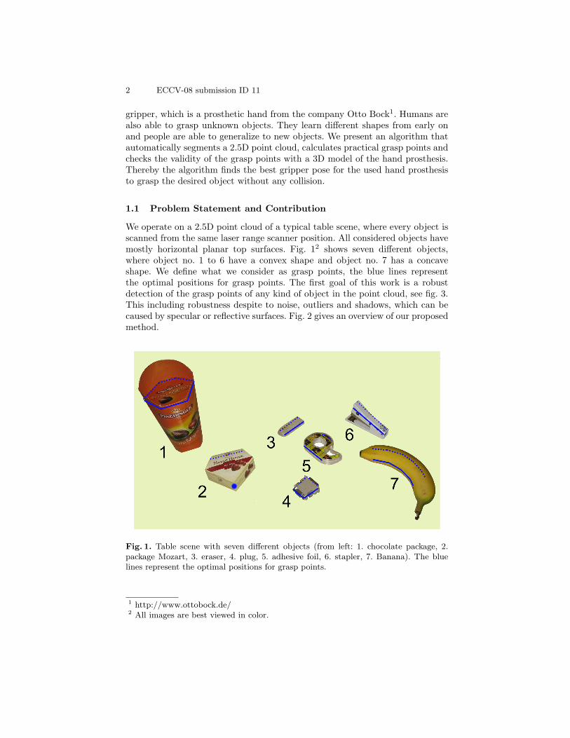
We operate on a 2.5D point cloud of a typical table scene, where every object isscanned from the same laser range scanner position. All considered objects havemostly horizontal planar top surfaces. Fig. 12 shows seven different objects,where object no. 1 to 6 have a convex shape and object no. 7 has a concaveshape. We define what we consider as grasp points, the blue lines representthe optimal positions for grasp points. The first goal of this work is a robustdetection of the grasp points of any kind of object in the point cloud, see fig. 3.This including robustness despite to noise, outliers and shadows, which can becaused by specular or reflective surfaces. Fig. 2 gives an overview of our proposedmethod.
Fig. 1. Table scene with seven different objects (from left: 1. chocolate package, 2.package Mozart, 3. eraser, 4. plug, 5. adhesive foil, 6. stapler, 7. Banana). The bluelines represent the optimal positions for grasp points.
1 http://www.ottobock.de/2 All images are best viewed in color.

ECCV-08 submission ID 11 3
Fig. 2. Overview of our grasp point detection and synthesis algorithm.
The algorithm consists of five main steps:
– Raw Data Preprocessing: The raw data points are preprocessed with a geo-metrical filter to reduce noise and outliers.
– Range Image Segmentation: This step identifies different objects based on a3D DeLaunay triangulation.
– Grasp Point Detection: Calculation of possible grasp points based on the topsurfaces of the objects.
– Validity Check of the Grasp Points: Considering surrounding objects andthe table surface as obstacles, find optimal gripper pose, which maximizesdistances to obstacles.
– Path Planning Tool: Transmission of the calculated object pose and handpose to the path planning tool.
Fig. 3. The figure shows the generated meshes with 12.437 object points and 81.691plane points from originally 100.843 points. The two shadows from laser and cameraand the grasp points (green colored) and the rim line (red colored) are clearly visible.The red points represent the calculated center of mass of the different top surfaces.
The second goal of our work is to analyze the calculated grasp points withthe help of a 3D model of the hand prosthesis, which we are using as gripper,

4 ECCV-08 submission ID 11
see fig. 4. It has three active fingers, the thumb, the index finger and the mid-dle finger. The last two fingers are just for cosmetic reasons. So the proposedalgorithm is based on two grasping points between the thumb and index finger.The 3D model of the gripper is realized with a Minolta VIVID 700 range scan-ner3. This 3D model enables it to calculate the optimal position and orientationof the gripper to successfully grasp the desired object. Furthermore it affordsto consider all surrounding objects to identify potential obstacles. As well theopening angle can be observed to detect a possible collision with the table. Allthese information is important for the path planner to calculated a successfullypath to grasp the desired object.
Fig. 4. This figure shows on the left side three different hand configurations to graspthe stapler. The left 3D model of the hand (red colored) shows the maximum positivehand orientation by 90◦, the right hand (black colored) shows the maximum negativehand orientation by −30◦ and the hand model in the middle (orange colored) showsthe optimum orientation by 60◦.
We simulate the complete grasping process with a commercial path planningtool from AMROSE4. The input is the detected object pose, the gripper pose,the environment model, the grasp points and a transformation between the robotcoordinate system and the laser range scanner coordinate system. The output isa collision free robot trajectory to the desired object. Before the robot executesthe trajectory, the user can check a simulation of the calculated trajectory.
The outline of the paper is as follows: The next Section 2 details the analysisof the objects and describes the calculation of possible grasp points. Section 3describes the implementation of a 3D model of the gripper. Section 4 shows ourresults and Section 5 finally concludes the paper.
3 http://www.konicaminolta.com/sensingusa/products/3d4 http://www.amrose.dk/

ECCV-08 submission ID 11 5
1.2 Related Work
Fagg and Arbib [2] developed the FARS model, which focuses especially onthe action-execution step. Nevertheless, no robotic application has been yet de-veloped following this path. Saxena et al. [3] developed a supervised learningalgorithm that is able to predict the grasp position of novel objects as a functionof 2D images. The work focuses on the task of identifying grasp positions. In ourwork we do not use learning, but we believe a priori that we consider possiblegrasp points. Saxena also defines for every object only one grasp point, in somecases objects can be grasped slanted. In our approach we calculate two grasppoints to realize a more stable grasp. Stansfield [4] developed a system for grasp-ing objects with unknown geometry. At the beginning every object was placedon a rotary disc. Then the object was rotated and translated under a laser rangescanner to generate a 3D model of the object. The scanned 3D model formed theinput to an expert system that planned the grasping process. This system wastested for several objects. Miller et al. [5] specify an automatic grasp planningsystem “GraspIt!” for hand configurations using shape primitives, by modelingan object as a sphere, cylinder, cone or box. They use a set of rules to gener-ate possible grasp positions. In our case the vision task is to detect edges andsurfaces of objects that are analyzed to calculate grasping points. We use a 3Dmodel of the hand prosthesis, which we are using as gripper to find an opti-mal grasping angle to grasp the object. Wang et al. [6] developed a frameworkof automatic grasping of unknown objects by using a laser scanner and a sim-ulation environment. Boughorbel et al. [7] aid industrial bin picking tasks anddeveloped a system that provides accurate 3D models of parts and objects in thebin to realize precise grasping operations, but their superquadrics based objectmodeling approach can only be used for rotationally symmetric objects. Bone etal. [8] presented an interesting approach, which combines online silhouette andstructured-light 3D object modeling with online grasp planning and executionwith parallel-jaw grippers. Their algorithm analyzes the solid model, generatesa robust force closure grasp and outputs the required gripper pose for graspingthe object. We analyze the validity of the calculated grasping points with a 3Dmodel of the hand, thereby our algorithm also outputs the required gripper poseto grasp the object. Borst et al. [9] show that it is not necessary in every caseto generate optimal grasp positions, however they reduce the number of candi-date grasps by randomly generating hand configuration dependent on the objectsurface. Their approach works well if the goal is to find a fairly good grasp asfast as possible and suitable. Kragic and Bjrkman [10] developed another vision-guided grasping system. Their approach was based on integrated monocular andbinocular cues from five cameras to provide robust 3D object information. Thesystem was applicable to well-textured, unknown objects. A three fingered handequipped with tactile sensors was used to grasp the object in an interactive man-ner. Recatala et. al. [11] developed a framework for the development of roboticapplications on the synthesis and execution of grasps. Li et al. [12] presenteda data-driven approach to grasp synthesis. Their algorithm uses a database of

6 ECCV-08 submission ID 11
captured human grasps to find the best grasp by matching hand shape to objectshape.
2 Grasp Point Detection
At the beginning the recorded point cloud from the laser range scanner shouldbe filtered with a low pass filter to reduce any noise and outliers. The range datasegmentation starts by detecting the surface of the table with a RANSAC [13]based plane fit. The segmentation of the remaining points is achieved with a 3Dmesh generation, based on the triangles calculated by a 3D DeLaunay triangu-lation [14].
The algorithm for grasp point detection finds the top surface of all objectswith a defined threshold of 3mm and generates a 2D DeLaunay triangulation,with this 2D surface information the rim points and feature edges of every objectcan be detected, see fig. 5. Then we calculate the center of mass for every objectstop surface (red colored points in fig. 5). For convex shapes the center of massis inside the surface, but for concave shapes the center of mass may be outsideas illustrated in fig. 5 by object no. 7.
Fig. 5. Top surfaces of the seven objects from fig. 1. The red lines represent the formof the top surfaces, the red point represents the center of mass. The green points arethe calculated grasp points, GP1 is the first grasp point with the shortest distance tothe center of mass and GP2 is the second grasp point.

ECCV-08 submission ID 11 7
The first grasp point (GP1) is that point along the rim line (red line), whichhas the shortest euclidian distance to the center of mass (red point). The secondgrasp point (GP2) is on the opposite rim line. Thereby, the first grasp point(GP1) should have with the second grasp (GP2) and the center of mass shouldlie on a line. To grasp an object on the top rim line can create a possible slippingthrough the fingers of the hand prosthesis. To avoid that, the height of thetop surface is calculated and both grasp points are shifted down. The shiftingdistance in our case is maximal 30mm, this distance is pretended through thegripper. Additionally we check that at least one of the shifted grasp points lieson a visible surface, i.e. is not shifted into thin air.
3 Feasibility of Objects Grasp Points
In order to successfully grasp an object it is not sufficient to find locally thebest grasp points, the algorithm must also decide like humans from which an-gle it is possible to grasp it. Moreover the algorithm checks the validity of thegrasp points. For that approach we rotate the 3D model of the hand prosthesisaround the rotation axis, which is defined through the grasp points. The rotationaxis of the hand is defined by the thumb and the index finger of the hand asillustrated in fig. 6 with the cyan colored points. At the beginning the hand isplaced accurately over the grasping object. This start position is defined witha grasping angle of 0◦. Furthermore the opening angle of the hand is set to itsmaximum. The algorithm checks for a collision of the hand with the table orother objects. If there is no collision our approach calculates the maximum andminimum possible rotation angles. We find the best gripper position and orien-tation by an averaging of the maximum and minimum possible rotation angles.Through that, the algorithm calculates the best gripper pose to grasp the desiredobject for the path planning tool. If there is a collision the grasp point detectionalgorithm calculates new grasp points for the desired object. Then the algorithmtakes for the first grasp point (GP1) the second shortest euclidian distance be-tween the center of mass and the rim line and all other calculations are repeated.
We decide to use the power crust algorithm for the surface reconstruction [15]of the 3D model of the hand prosthesis, because this algorithm delivers very goodresults and is quite fast. It realizes a construction which takes a sample of pointsfrom the surface of a 3D object and produces a surface mesh and an approxi-mate medial surface axis. The approach approximates the medial axis transform(MAT) of the object. Then it uses an inverse transform to produce the surfacerepresentation from the MAT.
This approach allows it to change the start position and orientation of thegripper online depending on the grasping object. The grasping pose depends onthe grasping object itself, surrounding objects and the calculated grasp points.The advantage of this novel implementation is that it realizes a alleviation forthe path planner to grasp an object fast and successfully, as illustrated in fig. 6.

8 ECCV-08 submission ID 11
Fig. 6. The rotation axis of the hand is defined through the thumb and the index fingerof the hand with the cyan colored points. This rotation axis must be aligned with theaxis defined by the grasp points.
4 Experiments and Results
In our work, we demonstrate that our grasp point detection algorithm for ob-jects with flat top surfaces shows promising results, see tab. 1. We evaluated thedetected grasp points by comparing them to the optimal grasp points as definedin fig. 1. The object segmentation and grasp point detection is performed by aPC with 3.2GHz dual-core processor and it takes about 30sec. to compute thegrasp points and to syntheses the calculated grasp points takes about 51sec., thiscalculation depends on the number of the surrounding objects and their shape.The algorithm is implemented in C++ using the Visualization Tool Kit (VTK)5.In testing of 10 different point clouds with the seven objects, the algorithm showsvery good results, see tab. 1. For the objects no. 1, 2 and 7 in some cases thealgorithm can not detect the pre-defined grasp points, because of shadows of thelaser range scanner. The difference of object no. 7 to all other considered objectsis that it has a concave and not a convex shape, which represents a problem formany published methods.
Tab. 2 shows the maximum positive grasping angle of every object and tab. 3shows the maximum negative grasping angle. These tables show also the reasonof the collision, which can be caused by the table, other surrounding objects orthe grasping object itself. Using these values we calculate the optimal 3D handpose to grasp the desired object, see tab. 4. The final grasping angle results asaverage from the maximum positive and negative grasps, where minimum andmaximum angles are +/-90◦. The first object illustrates that it is not ideal inevery case use a vertical gripper orientation as starting position to grasp anobject. The second object can be grasped with a reduced opening angle. In this
5 Open source software, http://public.kitware.com/vtk.

ECCV-08 submission ID 11 9
Table 1. Grasping rate of different objects.
No. Objects Grasp-Rate [%]1 chocolate package 70%2 package mozart 70%3 eraser 100%4 plug 100%5 adhesive foil 80%6 stapler 100%7 banana 80%
Overall 85.71%
case the distance between the grasp points is about 75mm, so the opening anglemust reduced to 75mm with a safety distance of 5mm to avoid a possible collisionwith the object itself at the beginning. After that step the optimal hand posecan be calculated again.
Table 2. Maximal positive grasping angle.
No. Objects Maximal positive Grasping Angle [◦]1 chocolate package 0◦ (object collision itself)2 package mozart 23◦ (object collision itself)3 eraser 35◦ (object collision with obj. no. 2)4 plug 90◦
5 adhesive foil 90◦ (table collision)6 stapler 90◦
7 banana 80◦ (object collision with obj. no. 6)
Fig. 7 shows the positive influence of the angle adjustment. Through thecalculation of the optimized grasping angle we realize a safer grasp. There is ahigher distance to the all surrounding objects. Thereby it realizes a faster andsafer calculation of the needed robot path with the path planning tool to graspthe desired object.
5 Conclusion and Future Work
In this paper we present a framework to successfully calculate grasp points of un-known objects in 2.5D point clouds from laser range data. The presented methodshows high reliability. We calculate the grasp points from the top surfaces. Thegrasp point detection approach can be applied to a reasonable set of objects.This idea can be applied to every gripper type with a suitable 3D model of theused gripper.

10 ECCV-08 submission ID 11
Table 3. Maximal negative grasping angle.
No. Objects Maximal negative Grasping Angle [◦]1 chocolate package −2◦ (object collision itself)2 package mozart −10◦ (table collision)3 eraser −10◦ (table collision)4 plug −5◦ (table collision)5 adhesive foil −15◦ (table collision)6 stapler −30◦ (table collision and object collision itself)7 banana −5◦ (object collision itself)
Table 4. Optimized grasping angle.
No. Objects Optimized Grasping Angle [◦]1 chocolate package −1◦
2 package mozart 16.5◦
3 eraser 22.5◦
4 plug 47.5◦
5 adhesive foil 52.5◦
6 stapler 60◦
7 banana 42.5◦
In the near future we will check the quality of the calculated grasp pointsdirectly on the robot, this time we simulate the total grasping process with acommercial path planning tool from AMROSE. We plan to use a deformablehand model to reduce the opening angle of the hand so we can model the closingof a gripper in the collision detection step. Also the rest of the robot arm willbe used in the collision detection step. Furthermore most experiments are insimulation and will be carried out to the real robot later.
References
1. Castiello, U.: The neurosience of grasping. Nature Reviews Neurosience 6 (2005)726–736
2. Fagg, A.H., Arbib, M.A.: Modeling parietal-premotor interactions in primate con-trol of grasping. Neural Networks 11 (1998) 1277–1303
3. Saxena, A., Driemeyer, J., Kearns, J., Osondu, C., Ng, A.Y.: Learning to graspnovel objects using vision. RSS Workshop on Manipulation for Human Environ-ments (2006)
4. Stansfield, S.A.: Robotic grasping of unknown objects: a knowledge-based ap-proach. The International Journal of Robotics Research 10 (1991) 314–326
5. Miller, A.T., Knoop, S.: Automatic grasp planning using shape primitives. Inter-national Conference on Robotics and Automation / ICRA 2 (2003) 1824–1829
6. Wang, B., Jiang, L.: Grasping unknown objects based on 3d model reconstruction.Proceedings of International Conference on Advanced Intelligent Mechatronics /ASME (2005) 461–466

ECCV-08 submission ID 11 11
Fig. 7. The left figure shows the calculated grasping angle without an angle adjustment.It shows a higher collision risk with object no. 1 as the right figure with an angleadjustment of 22.5◦, as illustrated in tab. 4.
7. Boughorbel, F., Zhang, Y.: Laser ranging and video imaging for bin picking.Assembly Automation 23 (2007) 53–59
8. Bone, G.M., Lambert, A., Edwards, M.: Automated modelling and robotic graspingof unknown three-dimensional objects. International Conference on Robotics andAutomation / ICRA (2008) 292–298
9. Borst, C., Fischer, M., Hirzinger, G.: Grasping the dice by dicing the grasp. Pro-ceedings of the IEEE/RSJ International Conference on Robotics and Systems /IROS 4 (2003) 3692–3697
10. Kragic, D., Bjorkman, M.: Strategies for object manipulation using foveal andperipheral vision. International Conference on Computer Vision Systems (2006)50–55
11. Recatala, G., Chinellato, E., A. P. Del Pobil, Mezouar, Y., Martinet, P.:Biologically-inspired 3d grasp synthesis based on visual exploration. AutonomousRobots 25 (2008) 59–70
12. Li, Y., Fu, J.L., Pollard, N.S.: Data-driven grasp synthesis using shape match-ing and task-based pruning. IEEE Transactions on Visulaization and ComputerGrasphics 13 (2007) 732–747
13. Fischler, M.A., Bolles, R.C.: Random sample consensus: A paradigm for modelfitting with applications to image analysis and automated cartography. Commu-nications of the ACM 24 (1981) 381–395
14. O’Rourke, J.: Computational geometry in c. Univ. Press (1998)15. Amenta, N., Choi, S., Kolluri, R.: The power crust. Sixth ACM Symposium on
Solid Modeling and Applications (2001) 249–260