Graphical User Interface for Simplified Neutron Transport ... · PDF fileGraphical User...
69
Graphical User Interface for Simplified Neutron Transport Calculations Phase 1 Final Report Instrument No: DE-SC0002321 July 20, 2009, through April 19, 2010 Recipient: Randolph Schwarz, Visual Editor Consultants Principal Investigator: Randolph Schwarz Teaming Members Randolph Schwarz of Visual Editor Consultants Leland L. Carter of Carter Monte Carlo Analysis, Inc. Alysia Schwarz of Visual Editor Consultants
Transcript of Graphical User Interface for Simplified Neutron Transport ... · PDF fileGraphical User...
Graphical User Interface for Simplified Neutron Transport Calculations
Phase 1 Final Report Instrument No: DE-SC0002321
July 20, 2009, through April 19, 2010
Recipient: Randolph Schwarz, Visual Editor Consultants
Principal Investigator: Randolph Schwarz
Teaming Members Randolph Schwarz of Visual Editor Consultants
Leland L. Carter of Carter Monte Carlo Analysis, Inc. Alysia Schwarz of Visual Editor Consultants
Table of Contents
LIST OF FIGURES ...........................................................................................................3
1.0 EXECUTIVE SUMMARY ......................................................................................4
2.0 SIGNIFICANT ACCOMPLISHMENTS ...............................................................4
2.1 OVERVIEW OF THE NUCWIZ PROGRAM.............................................................4 2.2 SUPPORTED SHIELDING CONFIGURATIONS .......................................................6 2.3 SUPPORTED SOURCE CONFIGURATIONS.............................................................9 2.4 SUPPORTED TALLY CONFIGURATIONS.............................................................12 2.5 SUPPORTED DATA .............................................................................................16 2.6 RUNNING FILES CREATED IN NUCWIZ.............................................................17 2.7 NUCWIZ PLOT OPTIONS ...................................................................................18
3.0 PROJECT ACTIVITIES .......................................................................................23
4.0 PRODUCTS DEVELOPED...................................................................................24
5.0 DETAILS OF THE NUCWIZ SOFTWARE PROGRAM .................................24
6.0 REFERENCES........................................................................................................24
APPENDIX A NUCWIZ USER’S MANUAL.............................................................26
Phase 1 Final Report Graphical User Interface for Simplified Neutron Transport Calculations
Page 3
List of Figures
FIGURE 2.1 THE NUCWIZ MAIN WINDOW........................................................................................................................6 FIGURE 2.2 SPHERICAL SHIELD GEOMETRY.....................................................................................................................7 FIGURE 2.3 CYLINDRICAL SHIELD GEOMETRY ................................................................................................................8 FIGURE 2.4 RECTANGULAR PARALLELEPIPED SHIELD GEOMETRY....................................................................................9 FIGURE 2.5 SPHERICAL SOURCE CONFIGURATION.........................................................................................................10 FIGURE 2.6 CYLINDRICAL SOURCE CONFIGURATION .....................................................................................................11 FIGURE 2.7 RECTANGULAR PARALLELEPIPED SOURCE CONFIGURATION ........................................................................12 FIGURE 2.8 CREATING A SURFACE TALLY ......................................................................................................................13 FIGURE 2.9 SPHERICAL TALLIES....................................................................................................................................14 FIGURE 2.10 CYLINDRICAL TALLIES ..............................................................................................................................15 FIGURE 2.11 RECTANGULAR PARALLELEPIPED TALLIES.................................................................................................16 FIGURE 2.12 MATERIAL LIBRARY WINDOW ....................................................................................................................17 FIGURE 2.13 RUNNING THE NUCWIZ INPUT FILE ..........................................................................................................18 FIGURE 2.14 THREE-DIMENSIONAL GEOMETRY WINDOW ..............................................................................................19 FIGURE 2.15 OBJECT LIST ............................................................................................................................................20 FIGURE 2.16 WIRE FRAME GEOMETRY DISPLAY ............................................................................................................21 FIGURE 2.17 CROSS-SECTIONAL VIEW OF THE GEOMETRY.............................................................................................22
Phase 1 Final Report Graphical User Interface for Simplified Neutron Transport Calculations
Page 4
1.0 Executive Summary
A number of codes perform simple photon physics calculations. The nuclear industry is lacking in similar tools to perform simplified neutron physics shielding calculations. With the increased importance of performing neutron calculations for homeland security applications and defense nuclear nonproliferation tasks, having an efficient method for performing simple neutron transport calculations becomes increasingly important.
Codes such as Monte Carlo N-particle (MCNP, reference 1) can perform the transport calculations; however, the technical details in setting up, running, and interpreting the required simulations are quite complex and typically go beyond the abilities of most users who need a simple answer to a neutron transport calculation. The work documented in this report resulted in the development of the NucWiz program, which can create an MCNP input file for a set of simple geometries, source, and detector configurations. The user selects source, shield, and tally configurations from a set of pre-defined lists, and the software creates a complete MCNP input file that can be optionally run and the results viewed inside NucWiz.
2.0 Significant Accomplishments The following sections list accomplishments for this grant, each based on the background and capabilities of the NucWiz program as outlined in the proposal. 2.1 Overview of the NucWiz Program
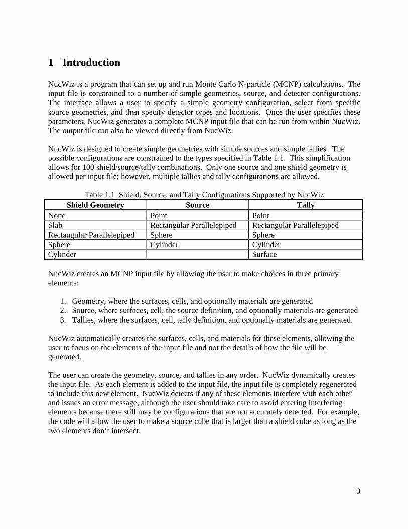
NucWiz is a program that can set up and run MCNP calculations. The input file is constrained to a number of simple geometry, source, and tally configurations. The interface allows a user to specify a simple geometry configuration, select from specific source geometries, and then specify tally types and locations. Once the user specifies these parameters, NucWiz generates a complete MCNP input file that can be run from within NucWiz. The output file can also be viewed directly from NucWiz. NucWiz is designed to create simple geometries with simple sources and simple tallies. The possible configurations are constrained to the types specified in Table 2.1. This simplification allows for 100 shield/source/tally combinations. Only one source and one shield geometry is allowed per input file; however, multiple tallies and tally configurations are allowed.
Phase 1 Final Report Graphical User Interface for Simplified Neutron Transport Calculations
Page 5
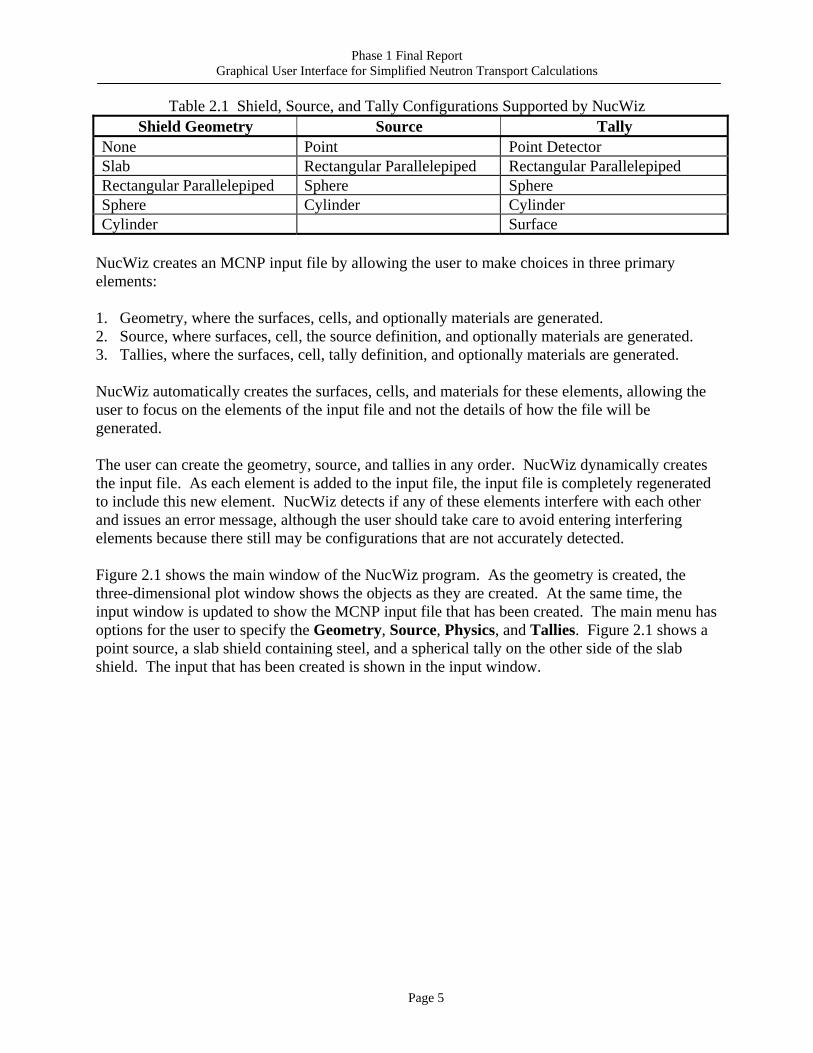
Table 2.1 Shield, Source, and Tally Configurations Supported by NucWiz Shield Geometry Source Tally
None Point Point Detector Slab Rectangular Parallelepiped Rectangular Parallelepiped Rectangular Parallelepiped Sphere Sphere Sphere Cylinder Cylinder Cylinder Surface
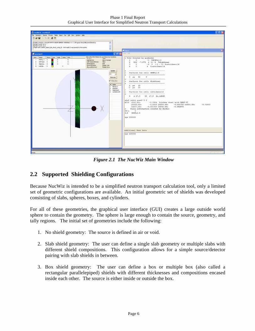
NucWiz creates an MCNP input file by allowing the user to make choices in three primary elements: 1. Geometry, where the surfaces, cells, and optionally materials are generated. 2. Source, where surfaces, cell, the source definition, and optionally materials are generated. 3. Tallies, where the surfaces, cell, tally definition, and optionally materials are generated. NucWiz automatically creates the surfaces, cells, and materials for these elements, allowing the user to focus on the elements of the input file and not the details of how the file will be generated. The user can create the geometry, source, and tallies in any order. NucWiz dynamically creates the input file. As each element is added to the input file, the input file is completely regenerated to include this new element. NucWiz detects if any of these elements interfere with each other and issues an error message, although the user should take care to avoid entering interfering elements because there still may be configurations that are not accurately detected. Figure 2.1 shows the main window of the NucWiz program. As the geometry is created, the three-dimensional plot window shows the objects as they are created. At the same time, the input window is updated to show the MCNP input file that has been created. The main menu has options for the user to specify the Geometry, Source, Physics, and Tallies. Figure 2.1 shows a point source, a slab shield containing steel, and a spherical tally on the other side of the slab shield. The input that has been created is shown in the input window.
Phase 1 Final Report Graphical User Interface for Simplified Neutron Transport Calculations
Page 6
Figure 2.1 The NucWiz Main Window
2.2 Supported Shielding Configurations
Because NucWiz is intended to be a simplified neutron transport calculation tool, only a limited set of geometric configurations are available. An initial geometric set of shields was developed consisting of slabs, spheres, boxes, and cylinders. For all of these geometries, the graphical user interface (GUI) creates a large outside world sphere to contain the geometry. The sphere is large enough to contain the source, geometry, and tally regions. The initial set of geometries include the following:
1. No shield geometry: The source is defined in air or void.
2. Slab shield geometry: The user can define a single slab geometry or multiple slabs with different shield compositions. This configuration allows for a simple source/detector pairing with slab shields in between.
3. Box shield geometry: The user can define a box or multiple box (also called a
rectangular parallelepiped) shields with different thicknesses and compositions encased inside each other. The source is either inside or outside the box.
Phase 1 Final Report Graphical User Interface for Simplified Neutron Transport Calculations
Page 7
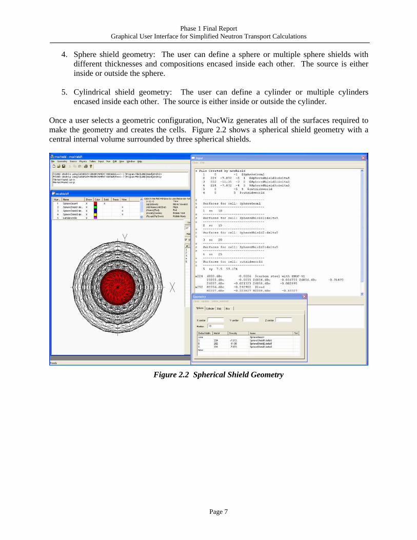
4. Sphere shield geometry: The user can define a sphere or multiple sphere shields with different thicknesses and compositions encased inside each other. The source is either inside or outside the sphere.
5. Cylindrical shield geometry: The user can define a cylinder or multiple cylinders encased inside each other. The source is either inside or outside the cylinder.
Once a user selects a geometric configuration, NucWiz generates all of the surfaces required to make the geometry and creates the cells. Figure 2.2 shows a spherical shield geometry with a central internal volume surrounded by three spherical shields.
Figure 2.2 Spherical Shield Geometry
Phase 1 Final Report Graphical User Interface for Simplified Neutron Transport Calculations
Page 8
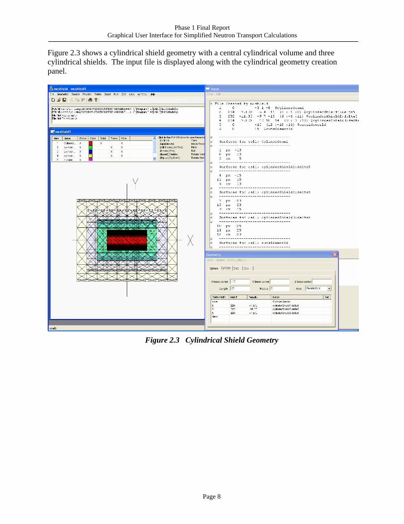
Figure 2.3 shows a cylindrical shield geometry with a central cylindrical volume and three cylindrical shields. The input file is displayed along with the cylindrical geometry creation panel.
Figure 2.3 Cylindrical Shield Geometry
Phase 1 Final Report Graphical User Interface for Simplified Neutron Transport Calculations
Page 9
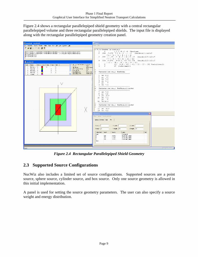
Figure 2.4 shows a rectangular parallelepiped shield geometry with a central rectangular parallelepiped volume and three rectangular parallelepiped shields. The input file is displayed along with the rectangular parallelepiped geometry creation panel.
Figure 2.4 Rectangular Parallelepiped Shield Geometry
2.3 Supported Source Configurations NucWiz also includes a limited set of source configurations. Supported sources are a point source, sphere source, cylinder source, and box source. Only one source geometry is allowed in this initial implementation. A panel is used for setting the source geometry parameters. The user can also specify a source weight and energy distribution.
Phase 1 Final Report Graphical User Interface for Simplified Neutron Transport Calculations
Page 10
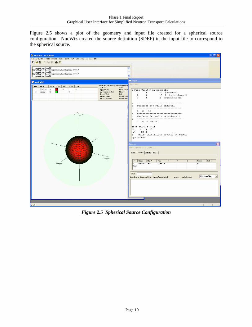
Figure 2.5 shows a plot of the geometry and input file created for a spherical source configuration. NucWiz created the source definition (SDEF) in the input file to correspond to the spherical source.
Figure 2.5 Spherical Source Configuration
Phase 1 Final Report Graphical User Interface for Simplified Neutron Transport Calculations
Page 11
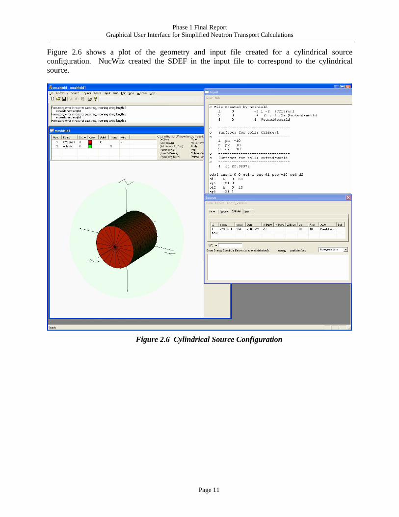
Figure 2.6 shows a plot of the geometry and input file created for a cylindrical source configuration. NucWiz created the SDEF in the input file to correspond to the cylindrical source.
Figure 2.6 Cylindrical Source Configuration
Phase 1 Final Report Graphical User Interface for Simplified Neutron Transport Calculations
Page 12
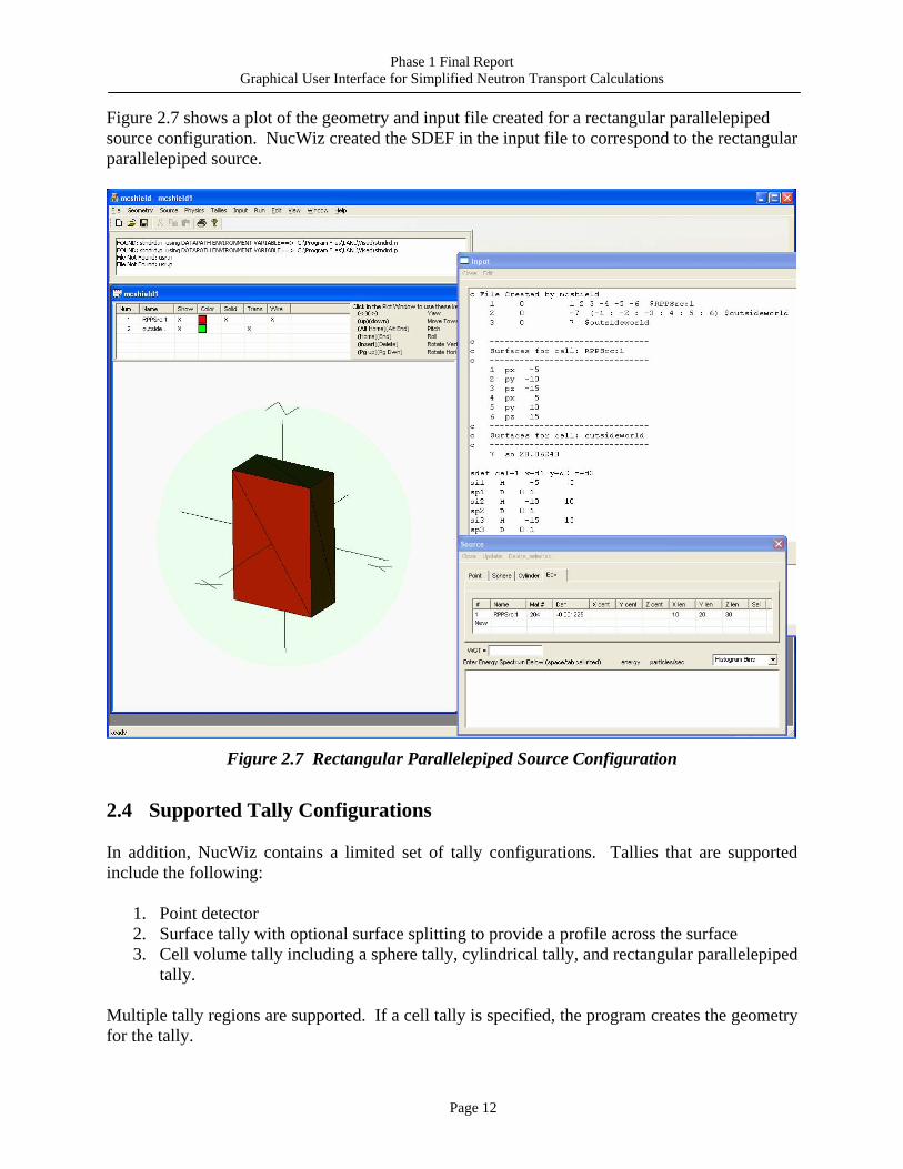
Figure 2.7 shows a plot of the geometry and input file created for a rectangular parallelepiped source configuration. NucWiz created the SDEF in the input file to correspond to the rectangular parallelepiped source.
Figure 2.7 Rectangular Parallelepiped Source Configuration
2.4 Supported Tally Configurations
In addition, NucWiz contains a limited set of tally configurations. Tallies that are supported include the following:
1. Point detector 2. Surface tally with optional surface splitting to provide a profile across the surface 3. Cell volume tally including a sphere tally, cylindrical tally, and rectangular parallelepiped
tally. Multiple tally regions are supported. If a cell tally is specified, the program creates the geometry for the tally.
Phase 1 Final Report Graphical User Interface for Simplified Neutron Transport Calculations
Page 13
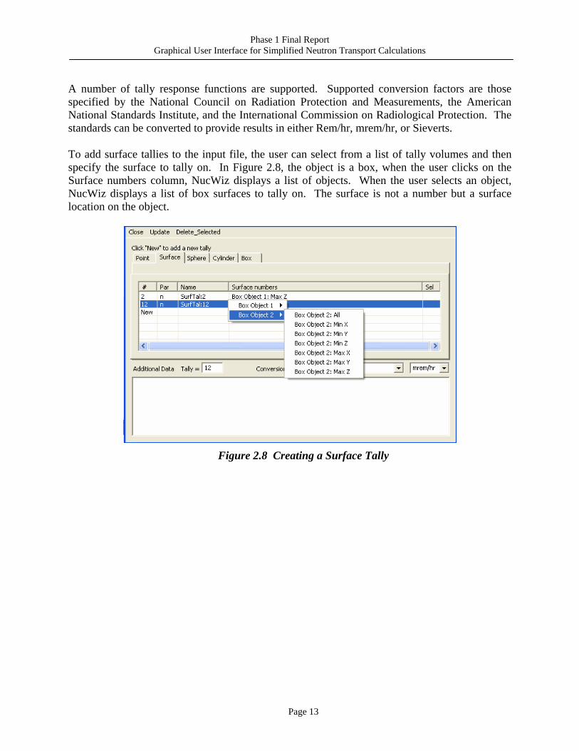
A number of tally response functions are supported. Supported conversion factors are those specified by the National Council on Radiation Protection and Measurements, the American National Standards Institute, and the International Commission on Radiological Protection. The standards can be converted to provide results in either Rem/hr, mrem/hr, or Sieverts. To add surface tallies to the input file, the user can select from a list of tally volumes and then specify the surface to tally on. In Figure 2.8, the object is a box, when the user clicks on the Surface numbers column, NucWiz displays a list of objects. When the user selects an object, NucWiz displays a list of box surfaces to tally on. The surface is not a number but a surface location on the object.
Figure 2.8 Creating a Surface Tally
Phase 1 Final Report Graphical User Interface for Simplified Neutron Transport Calculations
Page 14
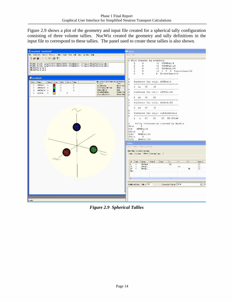
Figure 2.9 shows a plot of the geometry and input file created for a spherical tally configuration consisting of three volume tallies. NucWiz created the geometry and tally definitions in the input file to correspond to these tallies. The panel used to create these tallies is also shown.
Figure 2.9 Spherical Tallies
Phase 1 Final Report Graphical User Interface for Simplified Neutron Transport Calculations
Page 15
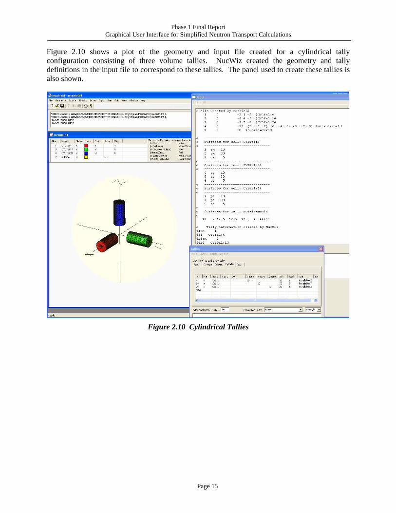
Figure 2.10 shows a plot of the geometry and input file created for a cylindrical tally configuration consisting of three volume tallies. NucWiz created the geometry and tally definitions in the input file to correspond to these tallies. The panel used to create these tallies is also shown.
Figure 2.10 Cylindrical Tallies
Phase 1 Final Report Graphical User Interface for Simplified Neutron Transport Calculations
Page 16
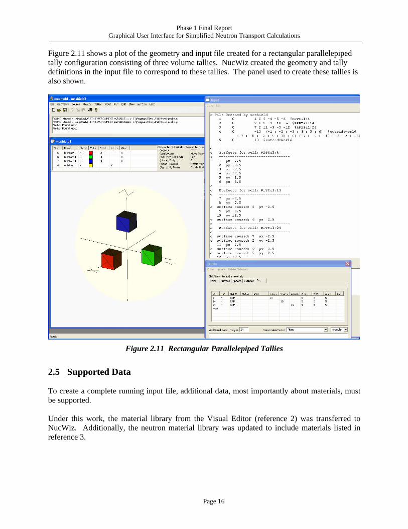
Figure 2.11 shows a plot of the geometry and input file created for a rectangular parallelepiped tally configuration consisting of three volume tallies. NucWiz created the geometry and tally definitions in the input file to correspond to these tallies. The panel used to create these tallies is also shown.
Figure 2.11 Rectangular Parallelepiped Tallies
2.5 Supported Data
To create a complete running input file, additional data, most importantly about materials, must be supported. Under this work, the material library from the Visual Editor (reference 2) was transferred to NucWiz. Additionally, the neutron material library was updated to include materials listed in reference 3.
Phase 1 Final Report Graphical User Interface for Simplified Neutron Transport Calculations
Page 17
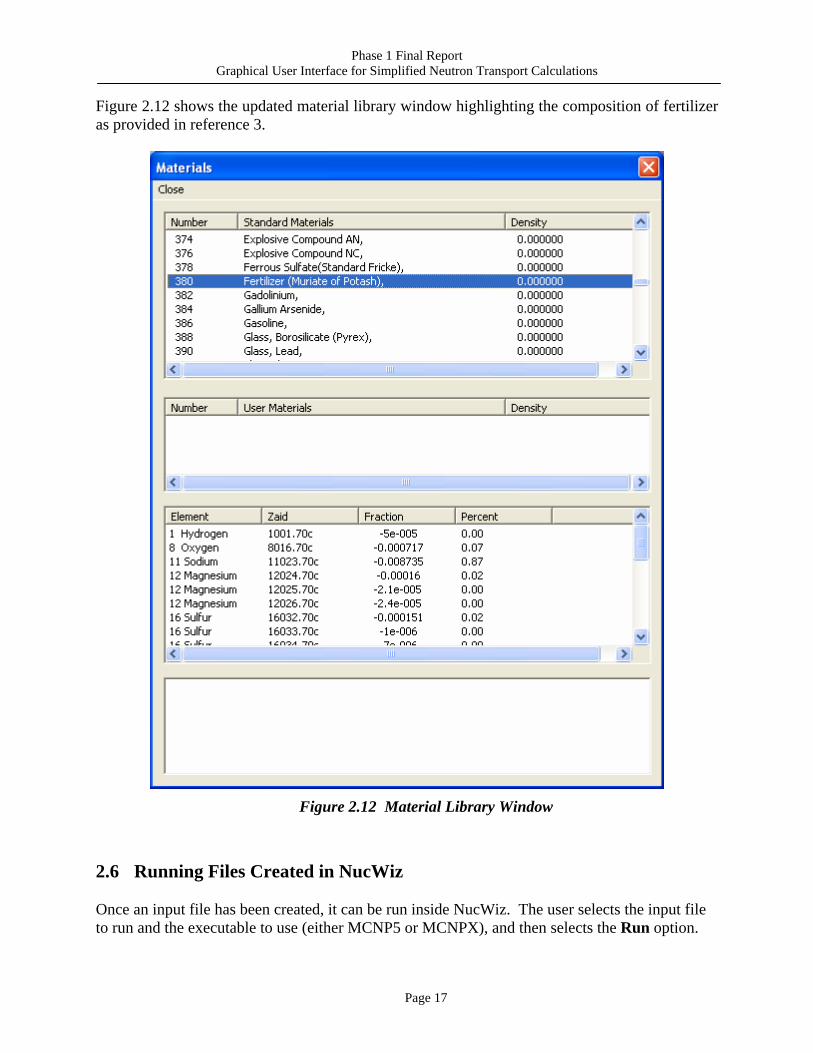
Figure 2.12 shows the updated material library window highlighting the composition of fertilizer as provided in reference 3.
Figure 2.12 Material Library Window
2.6 Running Files Created in NucWiz
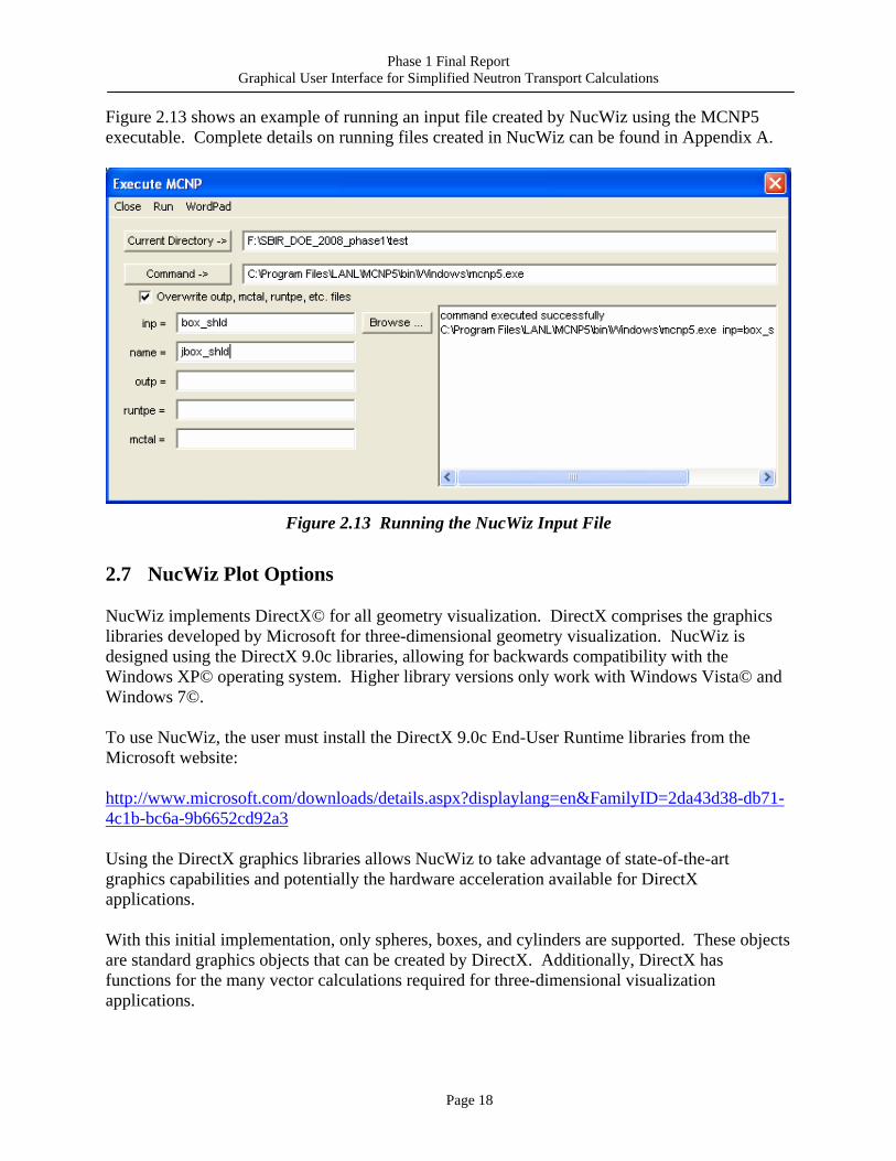
Once an input file has been created, it can be run inside NucWiz. The user selects the input file to run and the executable to use (either MCNP5 or MCNPX), and then selects the Run option.
Phase 1 Final Report Graphical User Interface for Simplified Neutron Transport Calculations
Page 18
Figure 2.13 shows an example of running an input file created by NucWiz using the MCNP5 executable. Complete details on running files created in NucWiz can be found in Appendix A.
Figure 2.13 Running the NucWiz Input File
2.7 NucWiz Plot Options
NucWiz implements DirectX© for all geometry visualization. DirectX comprises the graphics libraries developed by Microsoft for three-dimensional geometry visualization. NucWiz is designed using the DirectX 9.0c libraries, allowing for backwards compatibility with the Windows XP© operating system. Higher library versions only work with Windows Vista© and Windows 7©. To use NucWiz, the user must install the DirectX 9.0c End-User Runtime libraries from the Microsoft website: http://www.microsoft.com/downloads/details.aspx?displaylang=en&FamilyID=2da43d38-db71-4c1b-bc6a-9b6652cd92a3 Using the DirectX graphics libraries allows NucWiz to take advantage of state-of-the-art graphics capabilities and potentially the hardware acceleration available for DirectX applications. With this initial implementation, only spheres, boxes, and cylinders are supported. These objects are standard graphics objects that can be created by DirectX. Additionally, DirectX has functions for the many vector calculations required for three-dimensional visualization applications.
Phase 1 Final Report Graphical User Interface for Simplified Neutron Transport Calculations
Page 19
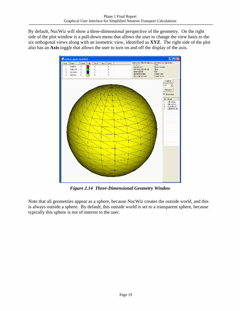
By default, NucWiz will show a three-dimensional perspective of the geometry. On the right side of the plot window is a pull-down menu that allows the user to change the view basis to the six orthogonal views along with an isometric view, identified as XYZ. The right side of the plot also has an Axis toggle that allows the user to turn on and off the display of the axis.
Figure 2.14 Three-Dimensional Geometry Window
Note that all geometries appear as a sphere, because NucWiz creates the outside world, and this is always outside a sphere. By default, this outside world is set to a transparent sphere, because typically this sphere is not of interest to the user.
Phase 1 Final Report Graphical User Interface for Simplified Neutron Transport Calculations
Page 20
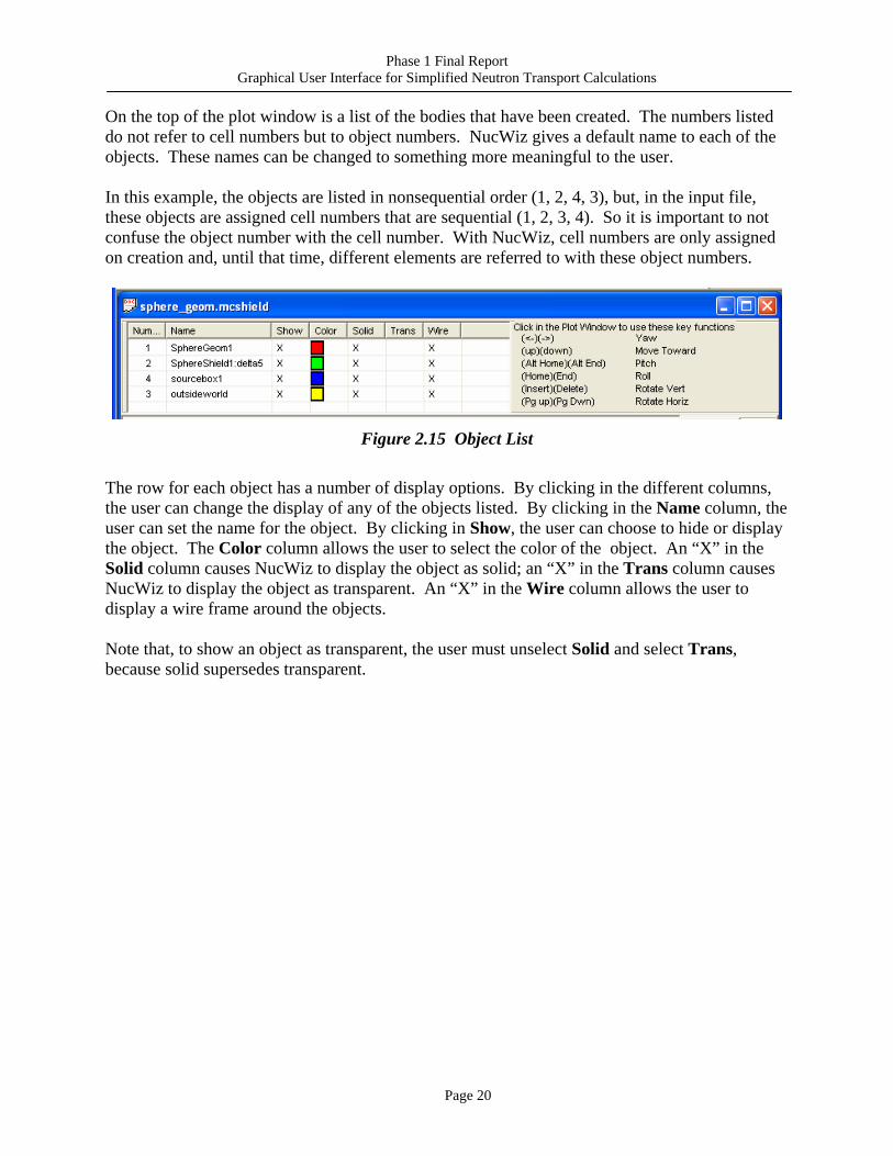
On the top of the plot window is a list of the bodies that have been created. The numbers listed do not refer to cell numbers but to object numbers. NucWiz gives a default name to each of the objects. These names can be changed to something more meaningful to the user. In this example, the objects are listed in nonsequential order (1, 2, 4, 3), but, in the input file, these objects are assigned cell numbers that are sequential (1, 2, 3, 4). So it is important to not confuse the object number with the cell number. With NucWiz, cell numbers are only assigned on creation and, until that time, different elements are referred to with these object numbers.
Figure 2.15 Object List
The row for each object has a number of display options. By clicking in the different columns, the user can change the display of any of the objects listed. By clicking in the Name column, the user can set the name for the object. By clicking in Show, the user can choose to hide or display the object. The Color column allows the user to select the color of the object. An “X” in the Solid column causes NucWiz to display the object as solid; an “X” in the Trans column causes NucWiz to display the object as transparent. An “X” in the Wire column allows the user to display a wire frame around the objects. Note that, to show an object as transparent, the user must unselect Solid and select Trans, because solid supersedes transparent.
Phase 1 Final Report Graphical User Interface for Simplified Neutron Transport Calculations
Page 21
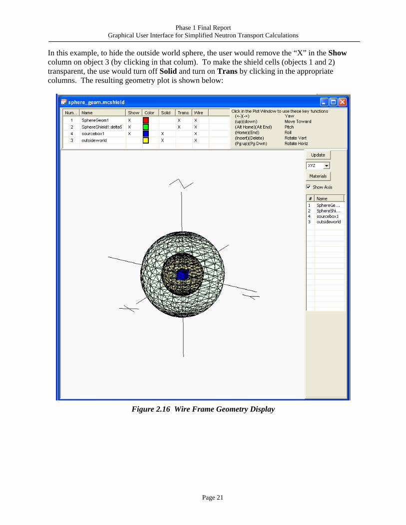
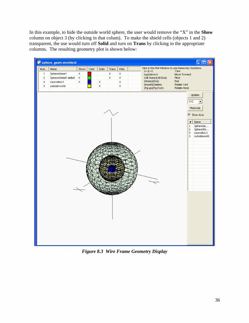
In this example, to hide the outside world sphere, the user would remove the “X” in the Show column on object 3 (by clicking in that colum). To make the shield cells (objects 1 and 2) transparent, the use would turn off Solid and turn on Trans by clicking in the appropriate columns. The resulting geometry plot is shown below:
Figure 2.16 Wire Frame Geometry Display
Phase 1 Final Report Graphical User Interface for Simplified Neutron Transport Calculations
Page 22
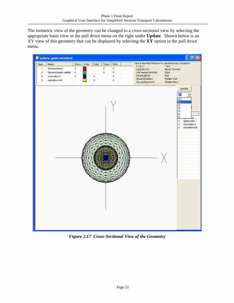
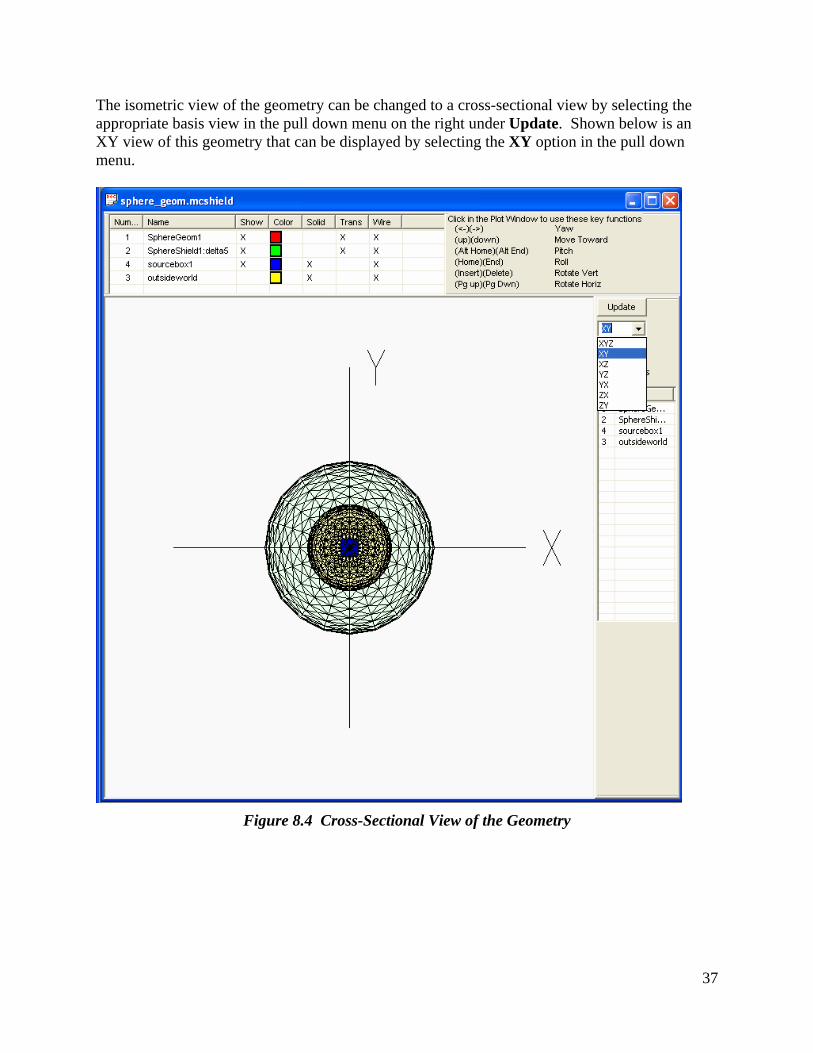
The isometric view of the geometry can be changed to a cross-sectional view by selecting the appropriate basis view in the pull down menu on the right under Update. Shown below is an XY view of this geometry that can be displayed by selecting the XY option in the pull down menu.
Figure 2.17 Cross-Sectional View of the Geometry
Phase 1 Final Report Graphical User Interface for Simplified Neutron Transport Calculations
Page 23
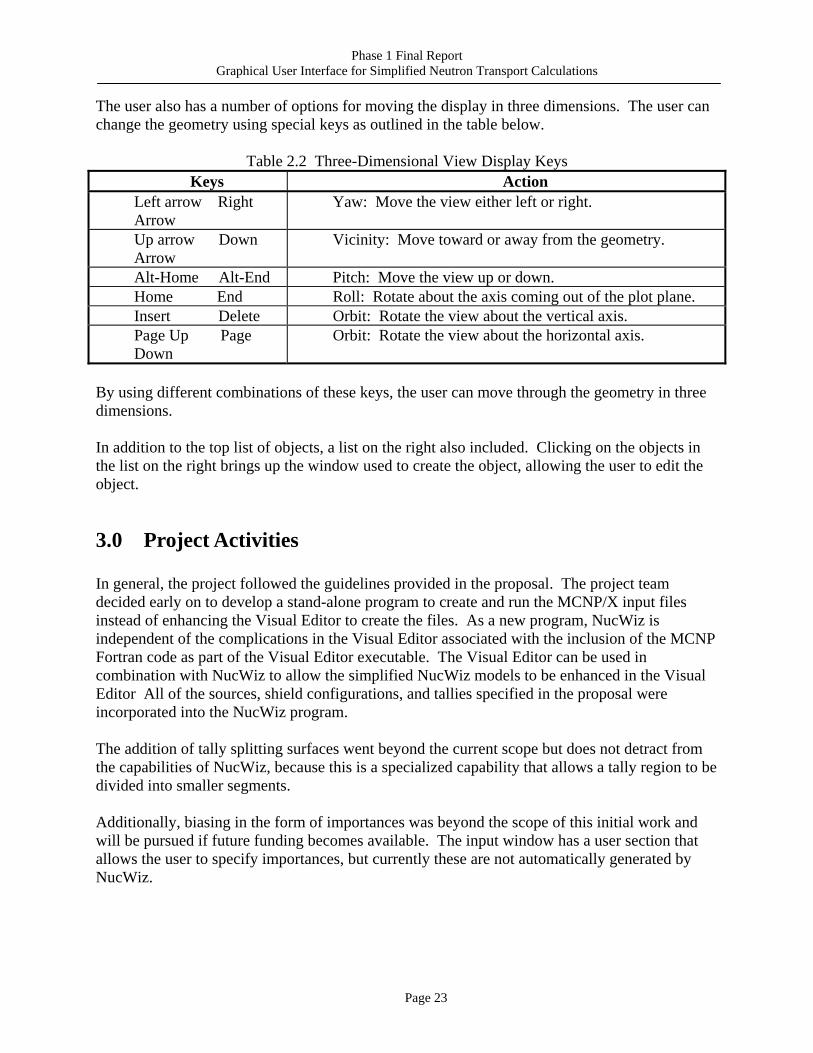
The user also has a number of options for moving the display in three dimensions. The user can change the geometry using special keys as outlined in the table below.
Table 2.2 Three-Dimensional View Display Keys Keys Action
Left arrow Right Arrow
Yaw: Move the view either left or right.
Up arrow Down Arrow
Vicinity: Move toward or away from the geometry.
Alt-Home Alt-End Pitch: Move the view up or down. Home End Roll: Rotate about the axis coming out of the plot plane. Insert Delete Orbit: Rotate the view about the vertical axis. Page Up Page Down
Orbit: Rotate the view about the horizontal axis.
By using different combinations of these keys, the user can move through the geometry in three dimensions. In addition to the top list of objects, a list on the right also included. Clicking on the objects in the list on the right brings up the window used to create the object, allowing the user to edit the object.
3.0 Project Activities
In general, the project followed the guidelines provided in the proposal. The project team decided early on to develop a stand-alone program to create and run the MCNP/X input files instead of enhancing the Visual Editor to create the files. As a new program, NucWiz is independent of the complications in the Visual Editor associated with the inclusion of the MCNP Fortran code as part of the Visual Editor executable. The Visual Editor can be used in combination with NucWiz to allow the simplified NucWiz models to be enhanced in the Visual Editor All of the sources, shield configurations, and tallies specified in the proposal were incorporated into the NucWiz program. The addition of tally splitting surfaces went beyond the current scope but does not detract from the capabilities of NucWiz, because this is a specialized capability that allows a tally region to be divided into smaller segments. Additionally, biasing in the form of importances was beyond the scope of this initial work and will be pursued if future funding becomes available. The input window has a user section that allows the user to specify importances, but currently these are not automatically generated by NucWiz.
Phase 1 Final Report Graphical User Interface for Simplified Neutron Transport Calculations
Page 24
4.0 Products Developed
The primary product developed from this Phase 1 project is the initial release of the NucWiz program. This initial release will be demonstrated in the Visual Editor workshops and may be distributed as a beta release through these workshops to get user input on its capabilities.
5.0 Details of the NucWiz Software Program The NucWiz program was written in C++ using Microsoft Visual Studio© 2008. The current version of NucWiz is 2S, released in May 2010. In this new approach to developing a GUI for creating MCNP input files, the project team decided to use the DirectX© libraries instead of the OpenGL© libraries. DirectX is recognized as the industry standard for gaming engines and gaming software. By using DirectX, advanced software and hardware support can be accessed to create and manipulate the graphics. The project team also decided to use the DirectX 9 libraries to be compatible with older operating systems. The current release of DirectX 11 will only run on Vista© and Windows 7©. Nucwiz is compiled using the following DirectX library: C:\Program Files\Microsoft DirectX SDK (August 2009)\Lib\x86 The following library files must be included when linking: d3dxof.lib, dxguid.lib, d3dx9d.lib, d3d9.lib. To run the NucWiz program, users must download the DirectX 9.0c runtime libraries or they will receive an error message indicating that the libraries cannot be found. This library can be downloaded from the Microsoft website. As of this writing, the library can be downloaded at this link: http://www.microsoft.com/downloads/details.aspx?displaylang=en&FamilyID=2da43d38-db71-4c1b-bc6a-9b6652cd92a3 NucWiz was tested by verifying that the files it created could be run in MCNP/X both from within NucWiz and also at the command prompt. The NucWiz user’s manual can be found in Appendix A with complete details on how to run the program.
6.0 References
1. MCNPX User’s Manual, version 2.6.0, April 2008. LA-CP-07-1473, D. B. Pelowitz, editor. Los Alamos National Laboratory, New Mexico.

Phase 1 Final Report Graphical User Interface for Simplified Neutron Transport Calculations
Page 25
2. MCNP Visual Editor Computer Code Manual, November 2005. L.L. Carter and R.A. Schwarz. Visual Editor Consultants, Richland, Washington.
3. Compendium of Material Composition Data for Radiation Transport Modeling, PNNL-
15870, April 2006. R.G. Williams III, C.J. Gesh, and R.T. Pagh. Pacific Northwest National Laboratory, Richland, Washington.

Phase 1 Final Report Graphical User Interface for Simplified Neutron Transport Calculations
Page 26
Appendix A NucWiz User’s Manual
NucWiz User’s Manual Nucwiz Version 2S
May 2010 Randolph Schwarz of Visual Editor Consultants
Leland L. Carter of Carter Monte Carlo Analysis, Inc.
Table of Contents
1 Introduction............................................................................................................................. 3 2 Creating the Geometry............................................................................................................ 4
2.1 Spherical Shields............................................................................................................. 4 2.2 Cylindrical Shields.......................................................................................................... 5 2.3 Slab Shields..................................................................................................................... 6 2.4 Box Shields ..................................................................................................................... 7
3 Adding Materials to the Geometry ......................................................................................... 8 4 Setting the Problem Mode .................................................................................................... 13 5 Creating the Source............................................................................................................... 15
5.1 Point Source .................................................................................................................. 18 5.2 Sphere Source ............................................................................................................... 19 5.3 Cylinder Source ............................................................................................................ 20 5.4 Box Source.................................................................................................................... 21
6 Creating Tallies..................................................................................................................... 22 6.1 Point Detector Tallies ................................................................................................... 22 6.2 Surface Tallies .............................................................................................................. 26 6.3 Cell Tallies .................................................................................................................... 29
7 The Input File and Inserting Additional User Data .............................................................. 31 8 NucWiz Plot Options ............................................................................................................ 33 9 Saving and Loading NucWiz Files ....................................................................................... 38 10 Running MCNP from Inside NucWiz............................................................................... 39 11 Viewing Output Files from Inside NucWiz ...................................................................... 42
2
List of Figures
Figure 2.1 Geometry Creation Window......................................................................................... 4 Figure 2.2 Spherical shield geometry ............................................................................................ 5 Figure 2.3 Cylindrical Shield Geometry....................................................................................... 6 Figure 2.4 Slab Shield Geometry................................................................................................... 7 Figure 2.5 Rectangular Parallelepiped Shield Geometry ............................................................. 8 Figure 3.1 Material Library Selection Window............................................................................. 9 Figure 3.2 Adding Materials to the Geometry Shields ................................................................ 10 Figure 3.3 DATAPATH Variable in Command Window ............................................................. 11 Figure 3.4 Creating the Geometry and Updating the Input File ................................................. 12 Figure 4.1 Setting the Problem Mode.......................................................................................... 13 Figure 4.2 Changing the Problem Mode ..................................................................................... 14 Figure 5.1 Example Source Window ........................................................................................... 15 Figure 5.2 Creating a Rectangular Source.................................................................................. 16 Figure 5.3 Adding the Source to the Input File ........................................................................... 17 Figure 5.4 Point Source Configuration ....................................................................................... 18 Figure 5.5 Spherical Source Configuration................................................................................. 19 Figure 5.6 Cylindrical Source Configuration.............................................................................. 20 Figure 5.7 Rectangular Parallelepiped Source Configuration ................................................... 21 Figure 6.1 Tallies Window........................................................................................................... 22 Figure 6.2 Creating Point Detector Tallies ................................................................................. 23 Figure 6.3 Specifying Additional Point Detector Tallies............................................................. 24 Figure 6.4 Point Detector Tallies Added to the Input File .......................................................... 25 Figure 6.5 Selecting the Surface of a Sphere to Tally On ........................................................... 26 Figure 6.66 Selecting a Surface of a Box to Tally On ................................................................. 27 Figure 6.7 Creating Box Cell Tallies........................................................................................... 30 Figure 7.1 Appending Additional User Data to the Input File.................................................... 32 Figure 8.1 Three-Dimensional Geometry Window...................................................................... 34 Figure 8.2 Object List .................................................................................................................. 35 Figure 8.3 Wire Frame Geometry Display .................................................................................. 36 Figure 8.4 Cross-Sectional View of the Geometry ...................................................................... 37 Figure 10.1 Run Window ............................................................................................................. 39 Figure 10.2 Specifying the Input and Output File Names ........................................................... 40 Figure 10.3 Selecting the Executable to Run............................................................................... 41 Figure 10.4 Executing the NucWiz Input File ............................................................................. 42 Figure 11.1 Displaying the Output File....................................................................................... 43
3
1 Introduction NucWiz is a program that can set up and run Monte Carlo N-particle (MCNP) calculations. The input file is constrained to a number of simple geometries, source, and detector configurations. The interface allows a user to specify a simple geometry configuration, select from specific source geometries, and then specify detector types and locations. Once the user specifies these parameters, NucWiz generates a complete MCNP input file that can be run from within NucWiz. The output file can also be viewed directly from NucWiz. NucWiz is designed to create simple geometries with simple sources and simple tallies. The possible configurations are constrained to the types specified in Table 1.1. This simplification allows for 100 shield/source/tally combinations. Only one source and one shield geometry is allowed per input file; however, multiple tallies and tally configurations are allowed.
Table 1.1 Shield, Source, and Tally Configurations Supported by NucWiz Shield Geometry Source Tally
None Point Point Slab Rectangular Parallelepiped Rectangular Parallelepiped Rectangular Parallelepiped Sphere Sphere Sphere Cylinder Cylinder Cylinder Surface NucWiz creates an MCNP input file by allowing the user to make choices in three primary elements:
1. Geometry, where the surfaces, cells, and optionally materials are generated 2. Source, where surfaces, cell, the source definition, and optionally materials are generated 3. Tallies, where the surfaces, cell, tally definition, and optionally materials are generated.
NucWiz automatically creates the surfaces, cells, and materials for these elements, allowing the user to focus on the elements of the input file and not the details of how the file will be generated. The user can create the geometry, source, and tallies in any order. NucWiz dynamically creates the input file. As each element is added to the input file, the input file is completely regenerated to include this new element. NucWiz detects if any of these elements interfere with each other and issues an error message, although the user should take care to avoid entering interfering elements because there still may be configurations that are not accurately detected. For example, the code will allow the user to make a source cube that is larger than a shield cube as long as the two elements don’t intersect.
4
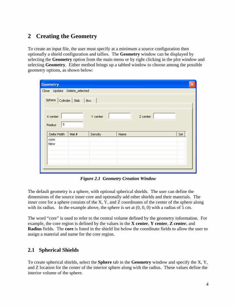
2 Creating the Geometry To create an input file, the user must specify at a minimum a source configuration then optionally a shield configuration and tallies. The Geometry window can be displayed by selecting the Geometry option from the main menu or by right clicking in the plot window and selecting Geometry. Either method brings up a tabbed window to choose among the possible geometry options, as shown below:
Figure 2.1 Geometry Creation Window
The default geometry is a sphere, with optional spherical shields. The user can define the dimensions of the source inner core and optionally add other shields and their materials. The inner core for a sphere consists of the X, Y, and Z coordinates of the center of the sphere along with its radius. In the example above, the sphere is set at (0, 0, 0) with a radius of 5 cm. The word “core” is used to refer to the central volume defined by the geometry information. For example, the core region is defined by the values in the X center, Y center, Z center, and Radius fields. The core is listed in the shield list below the coordinate fields to allow the user to assign a material and name for the core region.
2.1 Spherical Shields To create spherical shields, select the Sphere tab in the Geometry window and specify the X, Y, and Z location for the center of the interior sphere along with the radius. These values define the interior volume of the sphere.
5
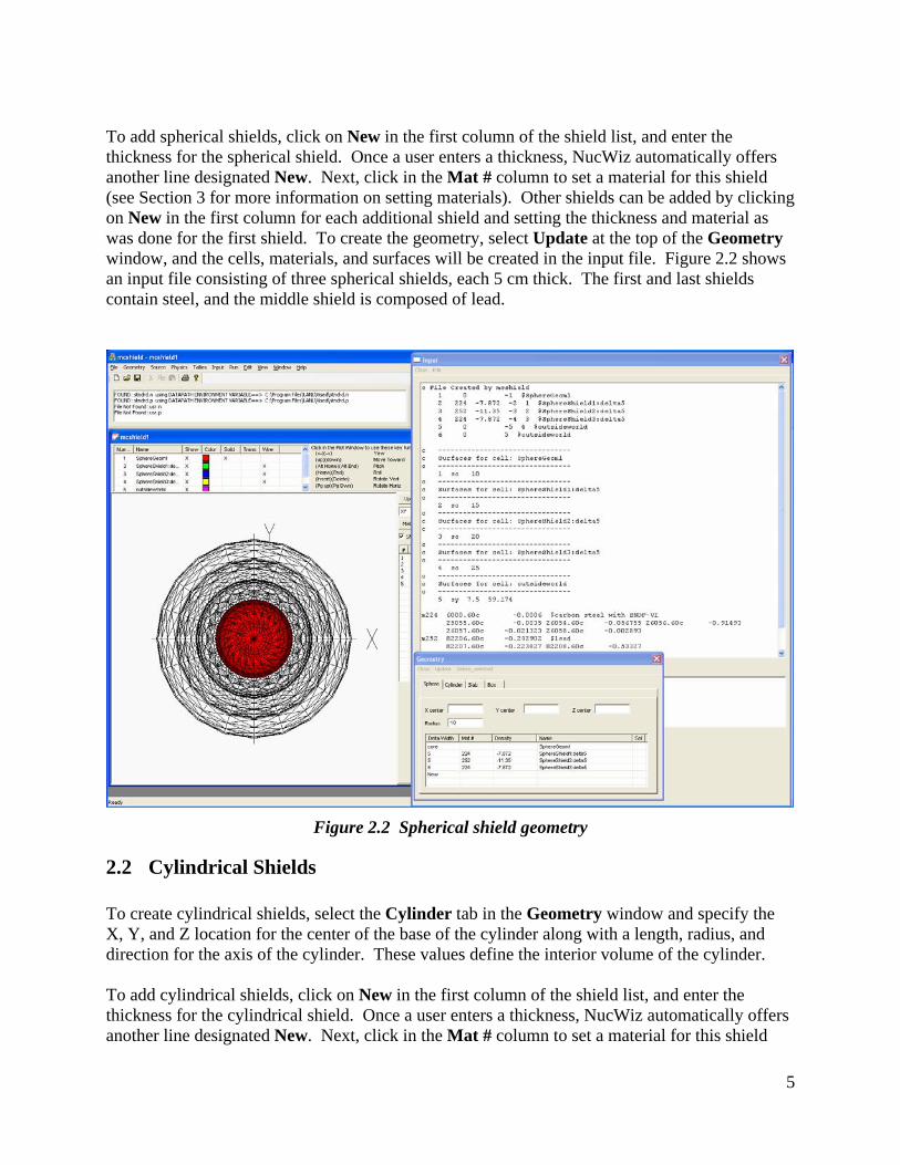
To add spherical shields, click on New in the first column of the shield list, and enter the thickness for the spherical shield. Once a user enters a thickness, NucWiz automatically offers another line designated New. Next, click in the Mat # column to set a material for this shield (see Section 3 for more information on setting materials). Other shields can be added by clicking on New in the first column for each additional shield and setting the thickness and material as was done for the first shield. To create the geometry, select Update at the top of the Geometry window, and the cells, materials, and surfaces will be created in the input file. Figure 2.2 shows an input file consisting of three spherical shields, each 5 cm thick. The first and last shields contain steel, and the middle shield is composed of lead.
Figure 2.2 Spherical shield geometry
2.2 Cylindrical Shields To create cylindrical shields, select the Cylinder tab in the Geometry window and specify the X, Y, and Z location for the center of the base of the cylinder along with a length, radius, and direction for the axis of the cylinder. These values define the interior volume of the cylinder. To add cylindrical shields, click on New in the first column of the shield list, and enter the thickness for the cylindrical shield. Once a user enters a thickness, NucWiz automatically offers another line designated New. Next, click in the Mat # column to set a material for this shield
6
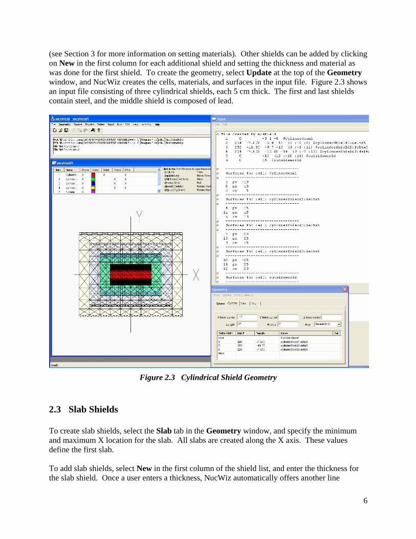
(see Section 3 for more information on setting materials). Other shields can be added by clicking on New in the first column for each additional shield and setting the thickness and material as was done for the first shield. To create the geometry, select Update at the top of the Geometry window, and NucWiz creates the cells, materials, and surfaces in the input file. Figure 2.3 shows an input file consisting of three cylindrical shields, each 5 cm thick. The first and last shields contain steel, and the middle shield is composed of lead.
Figure 2.3 Cylindrical Shield Geometry
2.3 Slab Shields To create slab shields, select the Slab tab in the Geometry window, and specify the minimum and maximum X location for the slab. All slabs are created along the X axis. These values define the first slab. To add slab shields, select New in the first column of the shield list, and enter the thickness for the slab shield. Once a user enters a thickness, NucWiz automatically offers another line
7
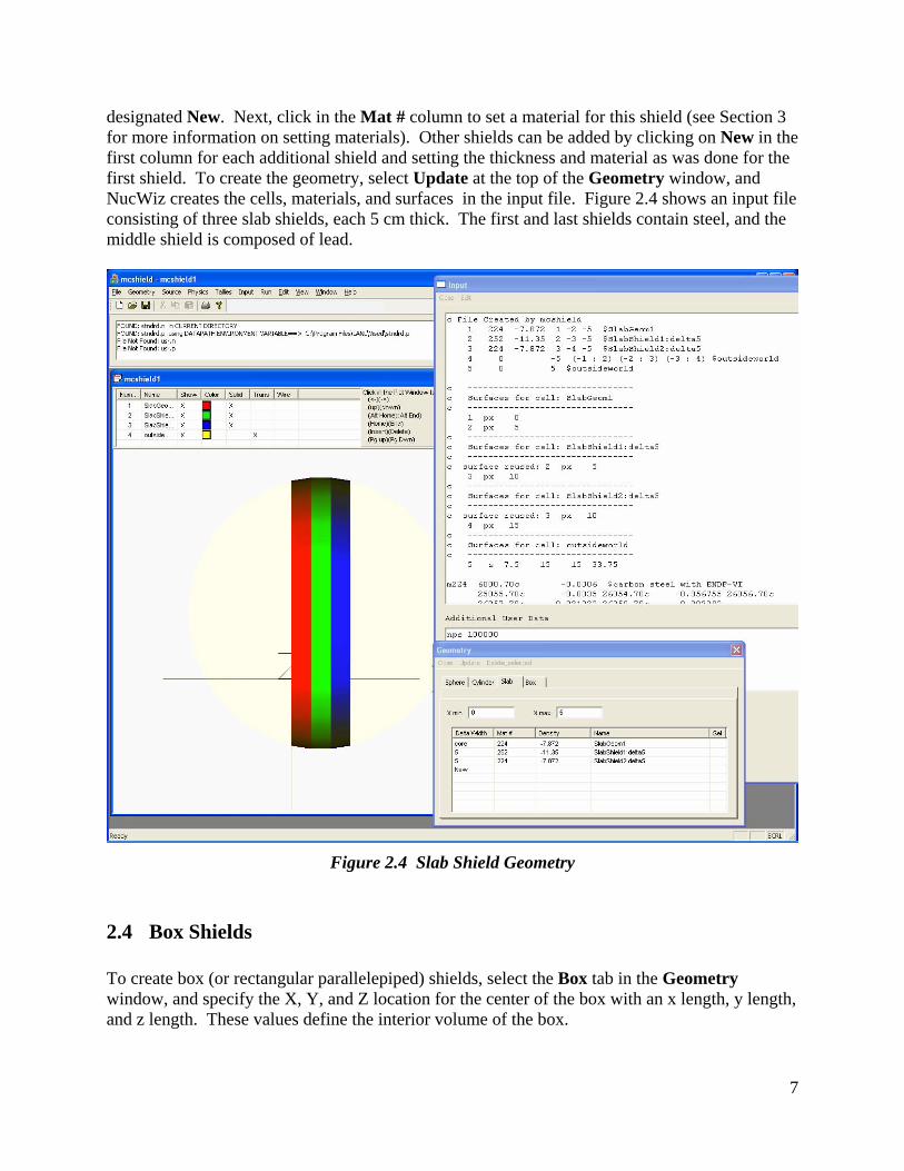
designated New. Next, click in the Mat # column to set a material for this shield (see Section 3 for more information on setting materials). Other shields can be added by clicking on New in the first column for each additional shield and setting the thickness and material as was done for the first shield. To create the geometry, select Update at the top of the Geometry window, and NucWiz creates the cells, materials, and surfaces in the input file. Figure 2.4 shows an input file consisting of three slab shields, each 5 cm thick. The first and last shields contain steel, and the middle shield is composed of lead.
Figure 2.4 Slab Shield Geometry
2.4 Box Shields To create box (or rectangular parallelepiped) shields, select the Box tab in the Geometry window, and specify the X, Y, and Z location for the center of the box with an x length, y length, and z length. These values define the interior volume of the box.
8
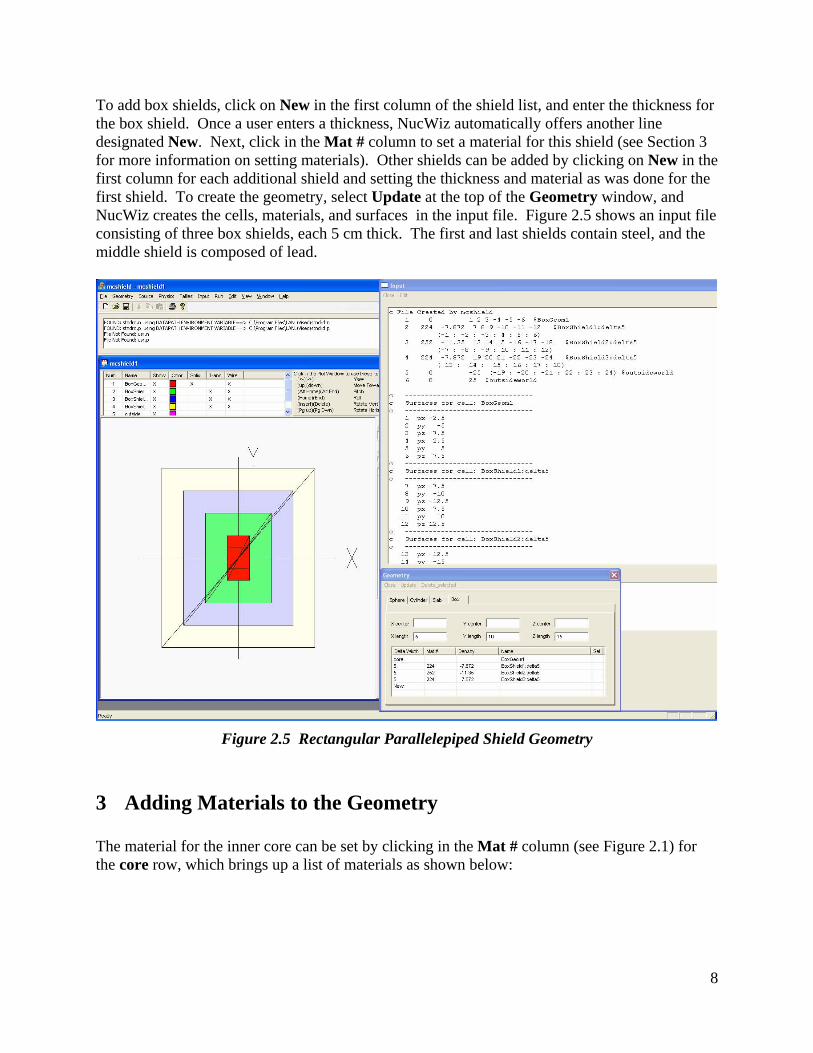
To add box shields, click on New in the first column of the shield list, and enter the thickness for the box shield. Once a user enters a thickness, NucWiz automatically offers another line designated New. Next, click in the Mat # column to set a material for this shield (see Section 3 for more information on setting materials). Other shields can be added by clicking on New in the first column for each additional shield and setting the thickness and material as was done for the first shield. To create the geometry, select Update at the top of the Geometry window, and NucWiz creates the cells, materials, and surfaces in the input file. Figure 2.5 shows an input file consisting of three box shields, each 5 cm thick. The first and last shields contain steel, and the middle shield is composed of lead.
Figure 2.5 Rectangular Parallelepiped Shield Geometry
3 Adding Materials to the Geometry The material for the inner core can be set by clicking in the Mat # column (see Figure 2.1) for the core row, which brings up a list of materials as shown below:
9
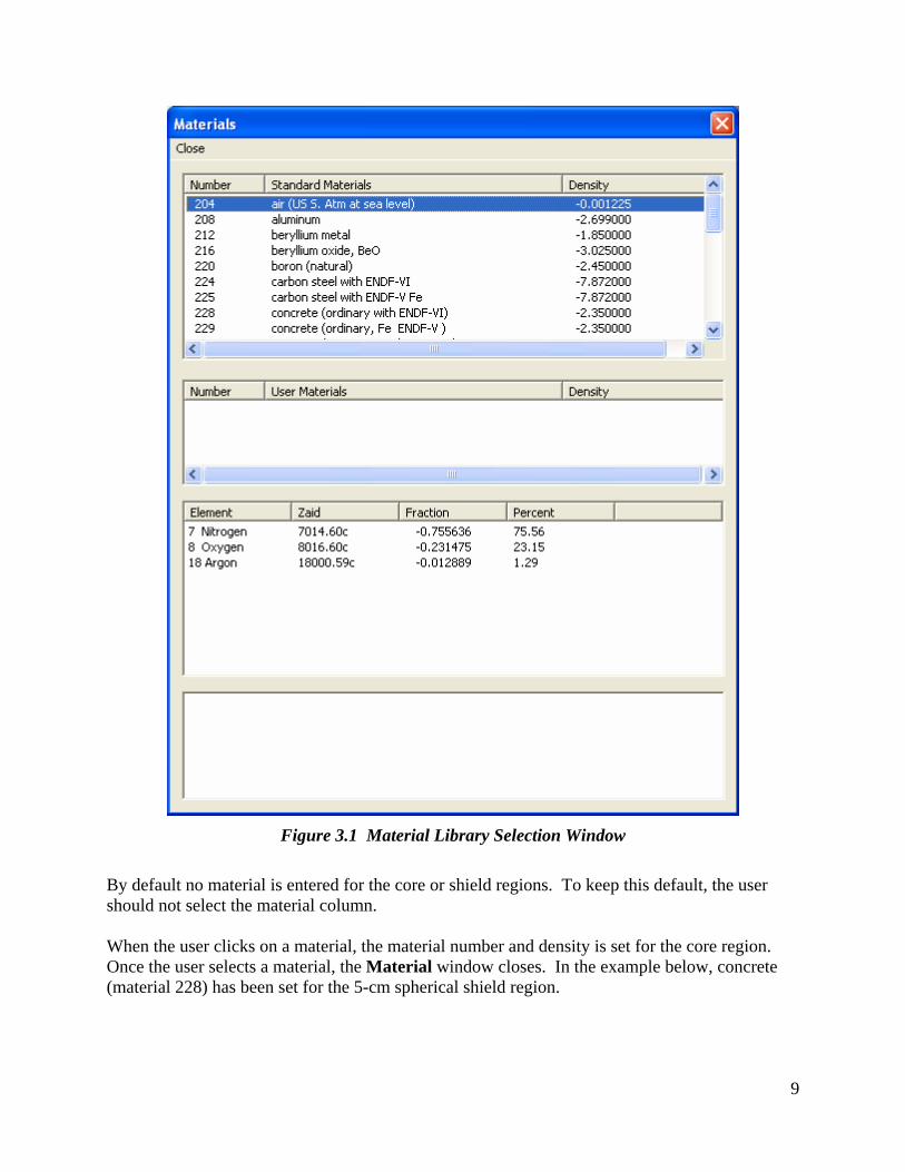
Figure 3.1 Material Library Selection Window
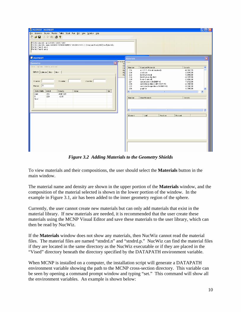
By default no material is entered for the core or shield regions. To keep this default, the user should not select the material column. When the user clicks on a material, the material number and density is set for the core region. Once the user selects a material, the Material window closes. In the example below, concrete (material 228) has been set for the 5-cm spherical shield region.
10
Figure 3.2 Adding Materials to the Geometry Shields
To view materials and their compositions, the user should select the Materials button in the main window. The material name and density are shown in the upper portion of the Materials window, and the composition of the material selected is shown in the lower portion of the window. In the example in Figure 3.1, air has been added to the inner geometry region of the sphere. Currently, the user cannot create new materials but can only add materials that exist in the material library. If new materials are needed, it is recommended that the user create these materials using the MCNP Visual Editor and save these materials to the user library, which can then be read by NucWiz. If the Materials window does not show any materials, then NucWiz cannot read the material files. The material files are named “stndrd.n” and “stndrd.p.” NucWiz can find the material files if they are located in the same directory as the NucWiz executable or if they are placed in the “Vised” directory beneath the directory specified by the DATAPATH environment variable. When MCNP is installed on a computer, the installation script will generate a DATAPATH environment variable showing the path to the MCNP cross-section directory. This variable can be seen by opening a command prompt window and typing “set.” This command will show all the environment variables. An example is shown below:

11
Figure 3.3 DATAPATH Variable in Command Window
NucWiz uses this DATAPATH to find the material libraries. It looks for a “Vised” directory that is at the same level as the MCNPXDATA directory. In the example above, the user would need to create a “C:\Program Files\LANL\Vised” directory and put the material libraries in this directory. If this directory exists, NucWiz will be able to read the material libraries without having the material libraries in the same directory as the NucWiz executable. If the DATAPATH variable was never set by the MCNP installation, the user can set this variable manually by right clicking on My Computer, then selecting the Advanced tab. Click on the Environment Variables button on the bottom of this tab. In the Environment Variables window, select New under System Variables.
12
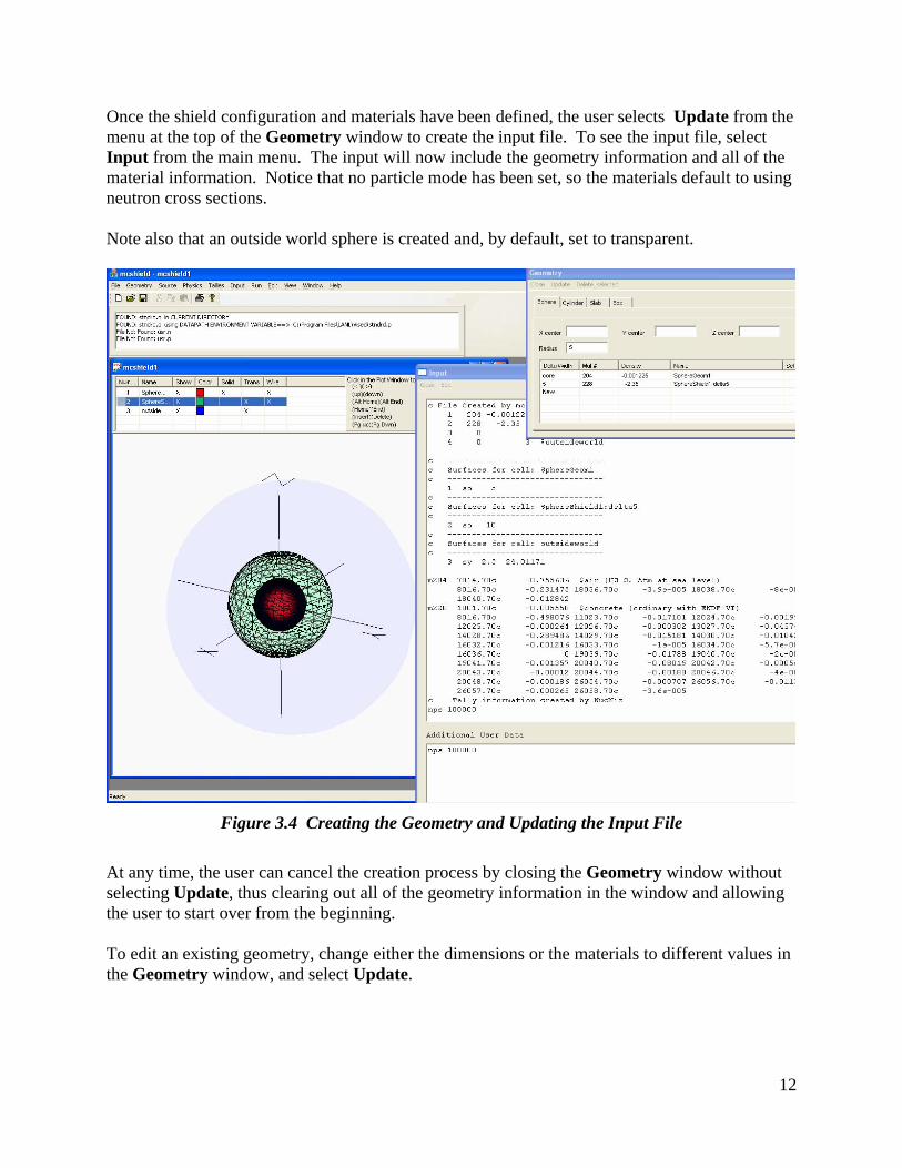
Once the shield configuration and materials have been defined, the user selects Update from the menu at the top of the Geometry window to create the input file. To see the input file, select Input from the main menu. The input will now include the geometry information and all of the material information. Notice that no particle mode has been set, so the materials default to using neutron cross sections. Note also that an outside world sphere is created and, by default, set to transparent.
Figure 3.4 Creating the Geometry and Updating the Input File
At any time, the user can cancel the creation process by closing the Geometry window without selecting Update, thus clearing out all of the geometry information in the window and allowing the user to start over from the beginning. To edit an existing geometry, change either the dimensions or the materials to different values in the Geometry window, and select Update.
13
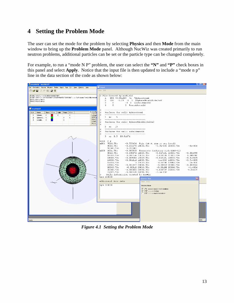
4 Setting the Problem Mode The user can set the mode for the problem by selecting Physics and then Mode from the main window to bring up the Problem Mode panel. Although NucWiz was created primarily to run neutron problems, additional particles can be set or the particle type can be changed completely. For example, to run a “mode N P” problem, the user can select the “N” and “P” check boxes in this panel and select Apply. Notice that the input file is then updated to include a “mode n p” line in the data section of the code as shown below:
Figure 4.1 Setting the Problem Mode
14
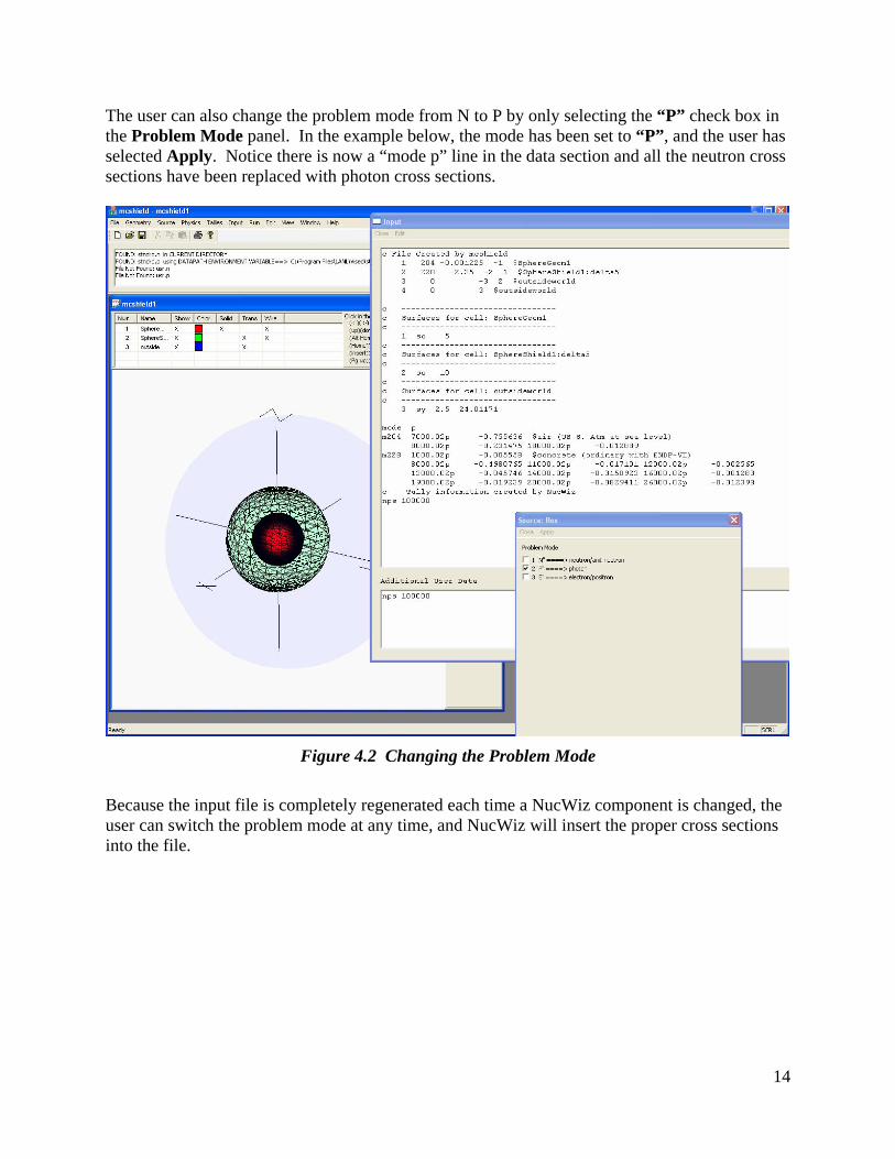
The user can also change the problem mode from N to P by only selecting the “P” check box in the Problem Mode panel. In the example below, the mode has been set to “P”, and the user has selected Apply. Notice there is now a “mode p” line in the data section and all the neutron cross sections have been replaced with photon cross sections.
Figure 4.2 Changing the Problem Mode
Because the input file is completely regenerated each time a NucWiz component is changed, the user can switch the problem mode at any time, and NucWiz will insert the proper cross sections into the file.

15
5 Creating the Source Once a geometry has been defined, the user can define the source. The Source window can be displayed by selecting the Source option from the main menu or by right clicking in the plot window and selecting Source. Either method brings up a tabbed window showing the possible source options as shown below. In this case, the Box tab has been selected.
Figure 5.1 Example Source Window
Notice that even though there are additional rows for more than one source description, only one source geometry is supported in this release of NucWiz. When the source configuration is defined, in this case by specifying the center and extent of the rectangular parallelepiped, a new cell is created to contain the source description and the source is placed in this cell. The user must take care to make sure the source description does not conflict with the geometry description. NucWiz will check to see if the source geometry conflicts with the shield geometry. If NucWiz detects a conflict, an error message will be displayed and the source will not be generated. The user will then need to modify the source description to eliminate the conflict with the existing geometry. To enter source information, click on New to add a new source. In the example below, a box source is created inside the existing sphere geometry, which has a length of 2 in X, Y, and Z.
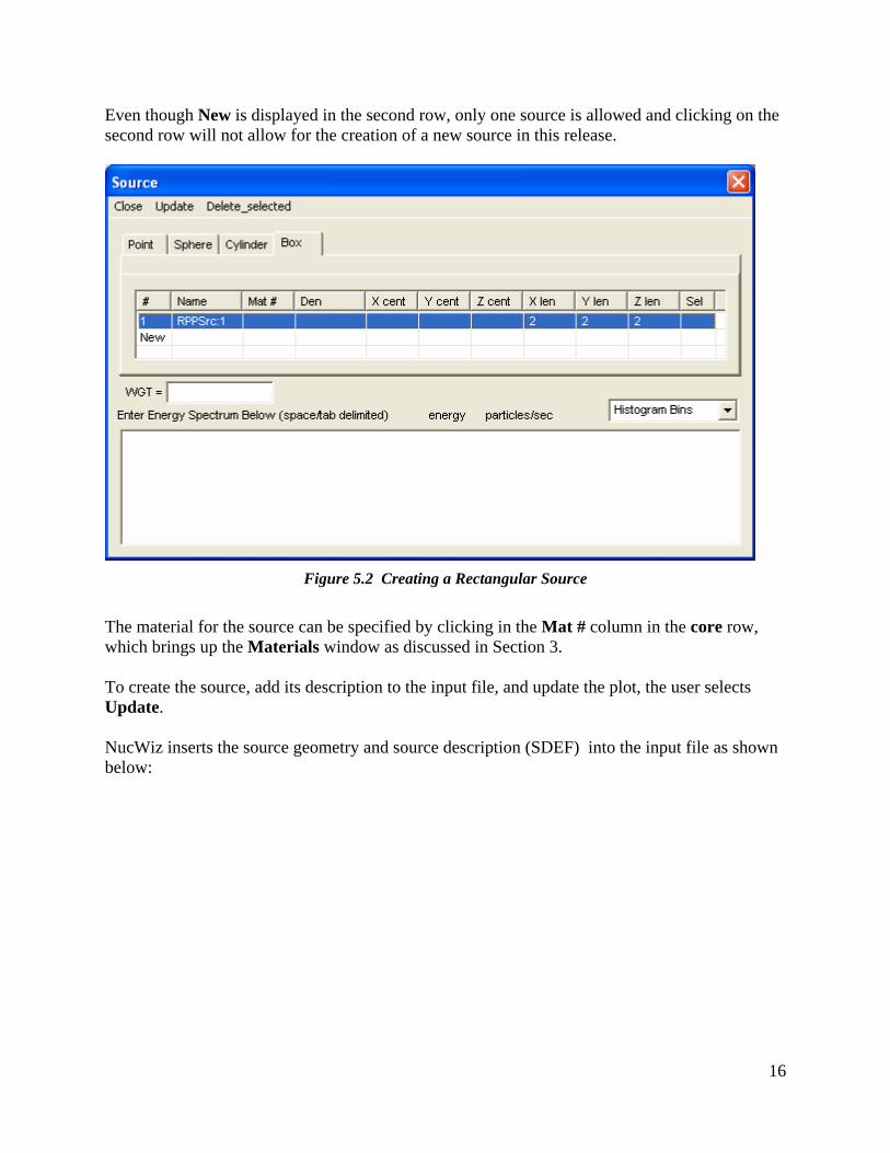
16
Even though New is displayed in the second row, only one source is allowed and clicking on the second row will not allow for the creation of a new source in this release.
Figure 5.2 Creating a Rectangular Source
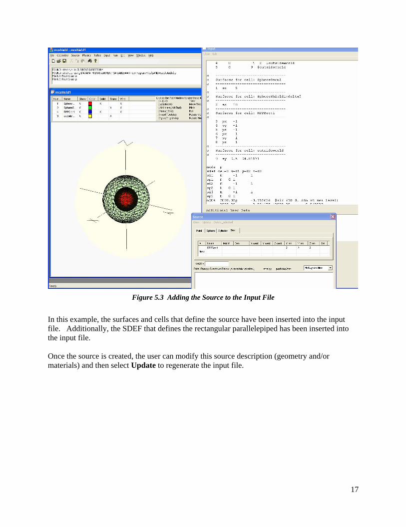
The material for the source can be specified by clicking in the Mat # column in the core row, which brings up the Materials window as discussed in Section 3. To create the source, add its description to the input file, and update the plot, the user selects Update. NucWiz inserts the source geometry and source description (SDEF) into the input file as shown below:
17
Figure 5.3 Adding the Source to the Input File
In this example, the surfaces and cells that define the source have been inserted into the input file. Additionally, the SDEF that defines the rectangular parallelepiped has been inserted into the input file. Once the source is created, the user can modify this source description (geometry and/or materials) and then select Update to regenerate the input file.
18
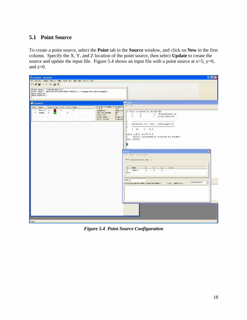
5.1 Point Source To create a point source, select the Point tab in the Source window, and click on New in the first column. Specify the X, Y, and Z location of the point source, then select Update to create the source and update the input file. Figure 5.4 shows an input file with a point source at x=5, y=0, and z=0.
Figure 5.4 Point Source Configuration
19
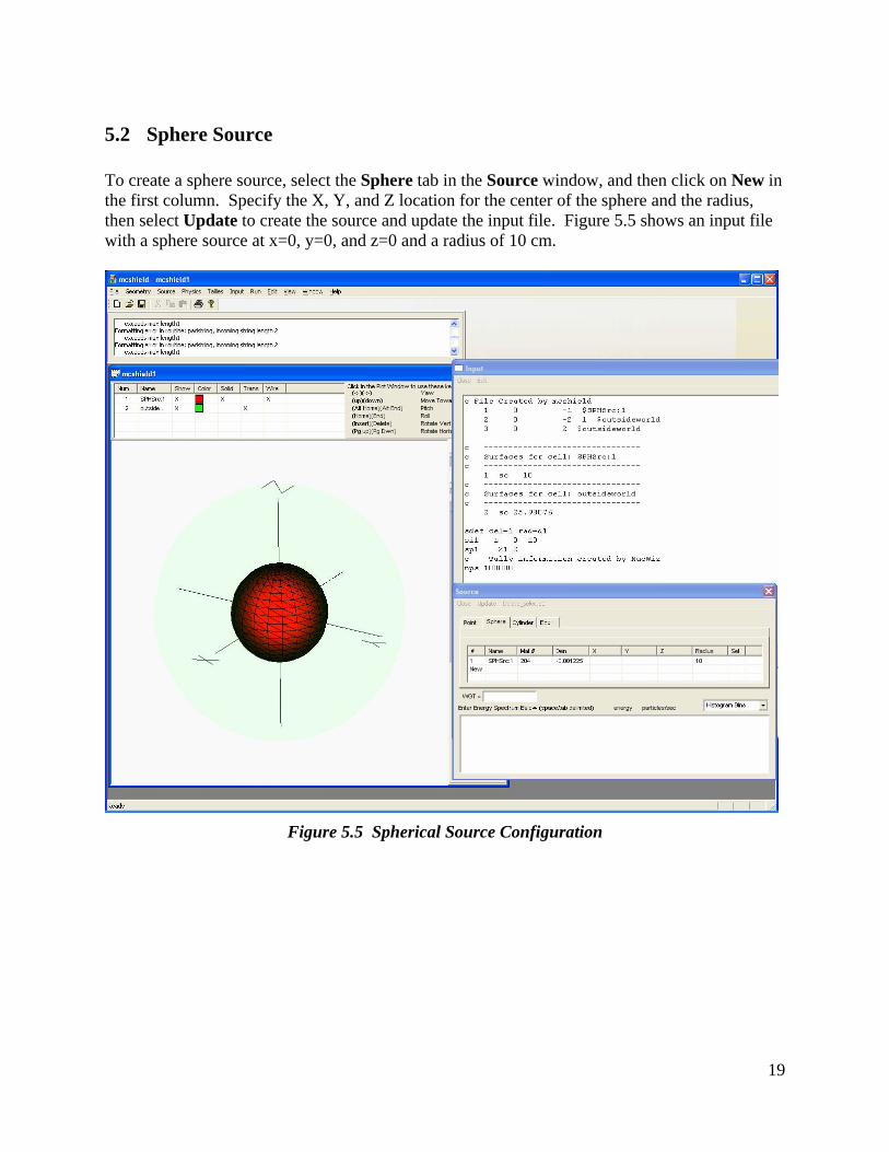
5.2 Sphere Source To create a sphere source, select the Sphere tab in the Source window, and then click on New in the first column. Specify the X, Y, and Z location for the center of the sphere and the radius, then select Update to create the source and update the input file. Figure 5.5 shows an input file with a sphere source at x=0, y=0, and z=0 and a radius of 10 cm.
Figure 5.5 Spherical Source Configuration
20
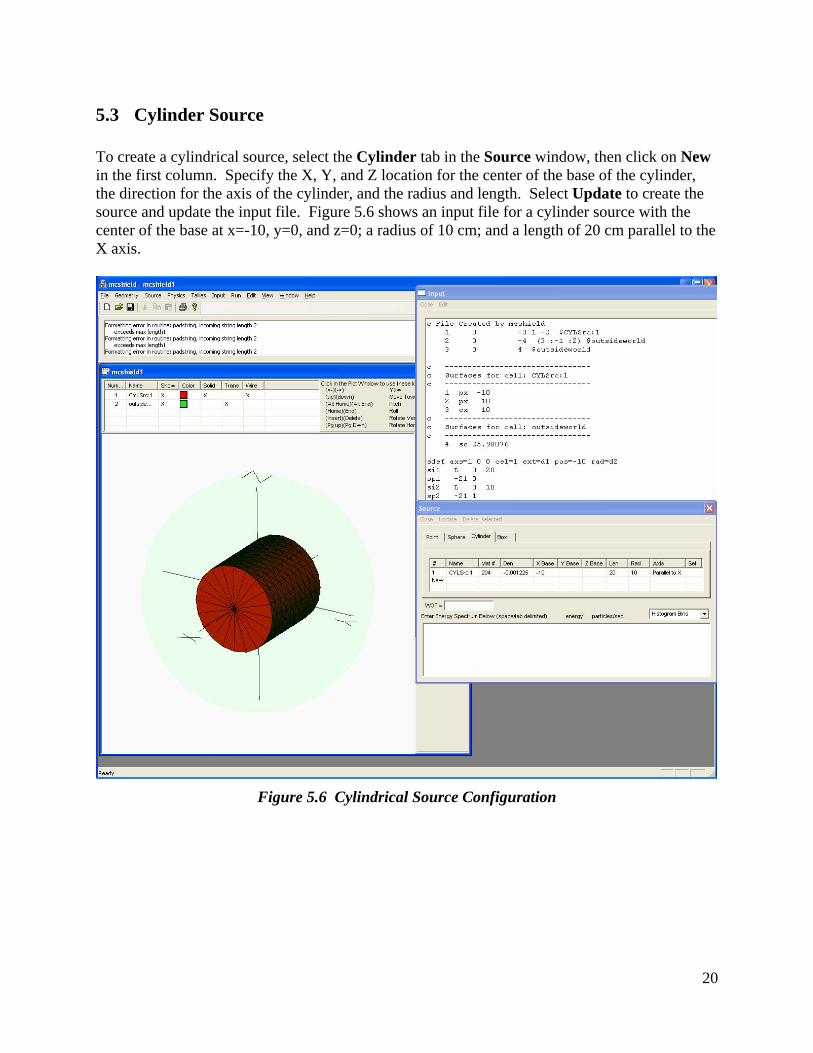
5.3 Cylinder Source To create a cylindrical source, select the Cylinder tab in the Source window, then click on New in the first column. Specify the X, Y, and Z location for the center of the base of the cylinder, the direction for the axis of the cylinder, and the radius and length. Select Update to create the source and update the input file. Figure 5.6 shows an input file for a cylinder source with the center of the base at x=-10, y=0, and z=0; a radius of 10 cm; and a length of 20 cm parallel to the X axis.
Figure 5.6 Cylindrical Source Configuration
21
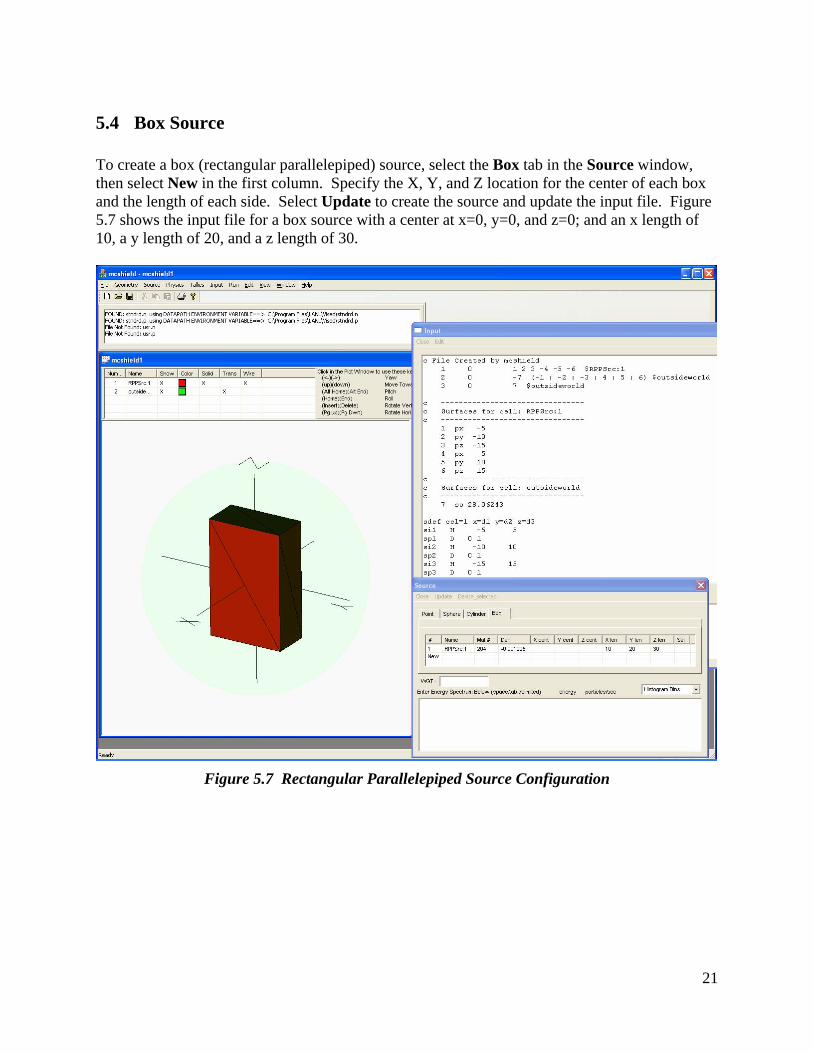
5.4 Box Source To create a box (rectangular parallelepiped) source, select the Box tab in the Source window, then select New in the first column. Specify the X, Y, and Z location for the center of each box and the length of each side. Select Update to create the source and update the input file. Figure 5.7 shows the input file for a box source with a center at x=0, y=0, and z=0; and an x length of 10, a y length of 20, and a z length of 30.
Figure 5.7 Rectangular Parallelepiped Source Configuration
22
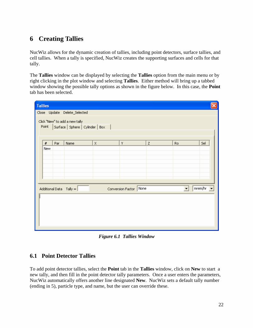
6 Creating Tallies NucWiz allows for the dynamic creation of tallies, including point detectors, surface tallies, and cell tallies. When a tally is specified, NucWiz creates the supporting surfaces and cells for that tally. The Tallies window can be displayed by selecting the Tallies option from the main menu or by right clicking in the plot window and selecting Tallies. Either method will bring up a tabbed window showing the possible tally options as shown in the figure below. In this case, the Point tab has been selected.
Figure 6.1 Tallies Window
6.1 Point Detector Tallies To add point detector tallies, select the Point tab in the Tallies window, click on New to start a new tally, and then fill in the point detector tally parameters. Once a user enters the parameters, NucWiz automatically offers another line designated New. NucWiz sets a default tally number (ending in 5), particle type, and name, but the user can override these.
23
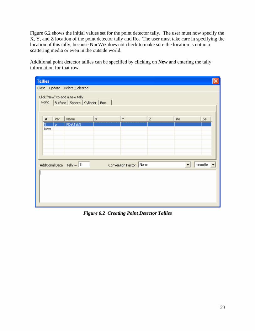
Figure 6.2 shows the initial values set for the point detector tally. The user must now specify the X, Y, and Z location of the point detector tally and Ro. The user must take care in specifying the location of this tally, because NucWiz does not check to make sure the location is not in a scattering media or even in the outside world. Additional point detector tallies can be specified by clicking on New and entering the tally information for that row.
Figure 6.2 Creating Point Detector Tallies
24
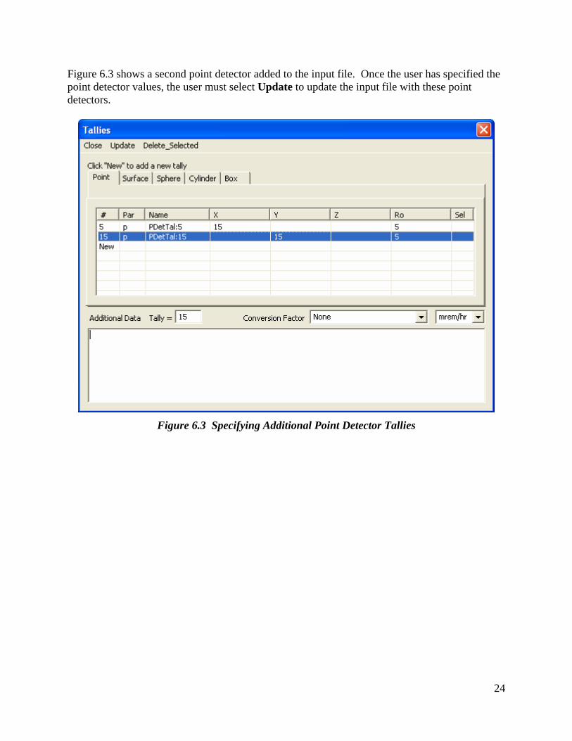
Figure 6.3 shows a second point detector added to the input file. Once the user has specified the point detector values, the user must select Update to update the input file with these point detectors.
Figure 6.3 Specifying Additional Point Detector Tallies
25
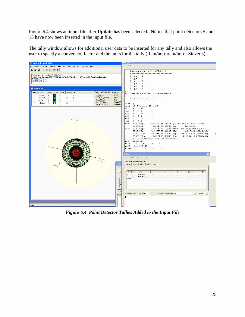
Figure 6.4 shows an input file after Update has been selected. Notice that point detectors 5 and 15 have now been inserted in the input file. The tally window allows for additional user data to be inserted for any tally and also allows the user to specify a conversion factor and the units for the tally (Rem/hr, mrem/hr, or Sieverts).
Figure 6.4 Point Detector Tallies Added to the Input File
26
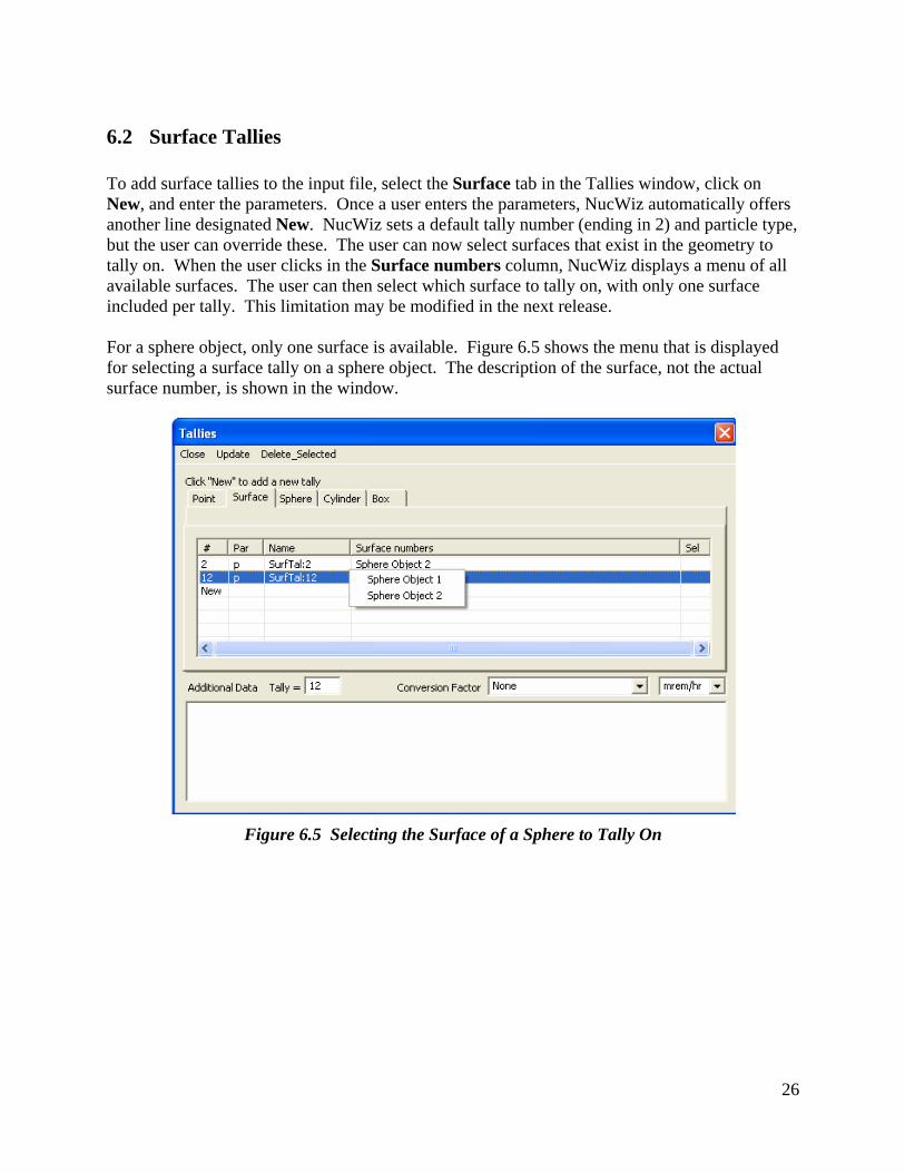
6.2 Surface Tallies To add surface tallies to the input file, select the Surface tab in the Tallies window, click on New, and enter the parameters. Once a user enters the parameters, NucWiz automatically offers another line designated New. NucWiz sets a default tally number (ending in 2) and particle type, but the user can override these. The user can now select surfaces that exist in the geometry to tally on. When the user clicks in the Surface numbers column, NucWiz displays a menu of all available surfaces. The user can then select which surface to tally on, with only one surface included per tally. This limitation may be modified in the next release. For a sphere object, only one surface is available. Figure 6.5 shows the menu that is displayed for selecting a surface tally on a sphere object. The description of the surface, not the actual surface number, is shown in the window.
Figure 6.5 Selecting the Surface of a Sphere to Tally On
27
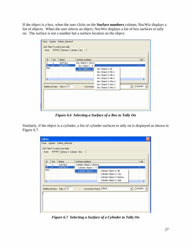
If the object is a box, when the user clicks on the Surface numbers column, NucWiz displays a list of objects. When the user selects an object, NucWiz displays a list of box surfaces to tally on. The surface is not a number but a surface location on the object.
Figure 6.6 Selecting a Surface of a Box to Tally On
Similarly, if the object is a cylinder, a list of cylinder surfaces to tally on is displayed as shown in Figure 6.7.
Figure 6.7 Selecting a Surface of a Cylinder to Tally On
28
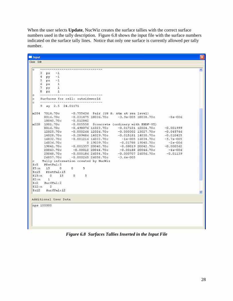
When the user selects Update, NucWiz creates the surface tallies with the correct surface numbers used in the tally description. Figure 6.8 shows the input file with the surface numbers indicated on the surface tally lines. Notice that only one surface is currently allowed per tally number.
Figure 6.8 Surfaces Tallies Inserted in the Input File
29
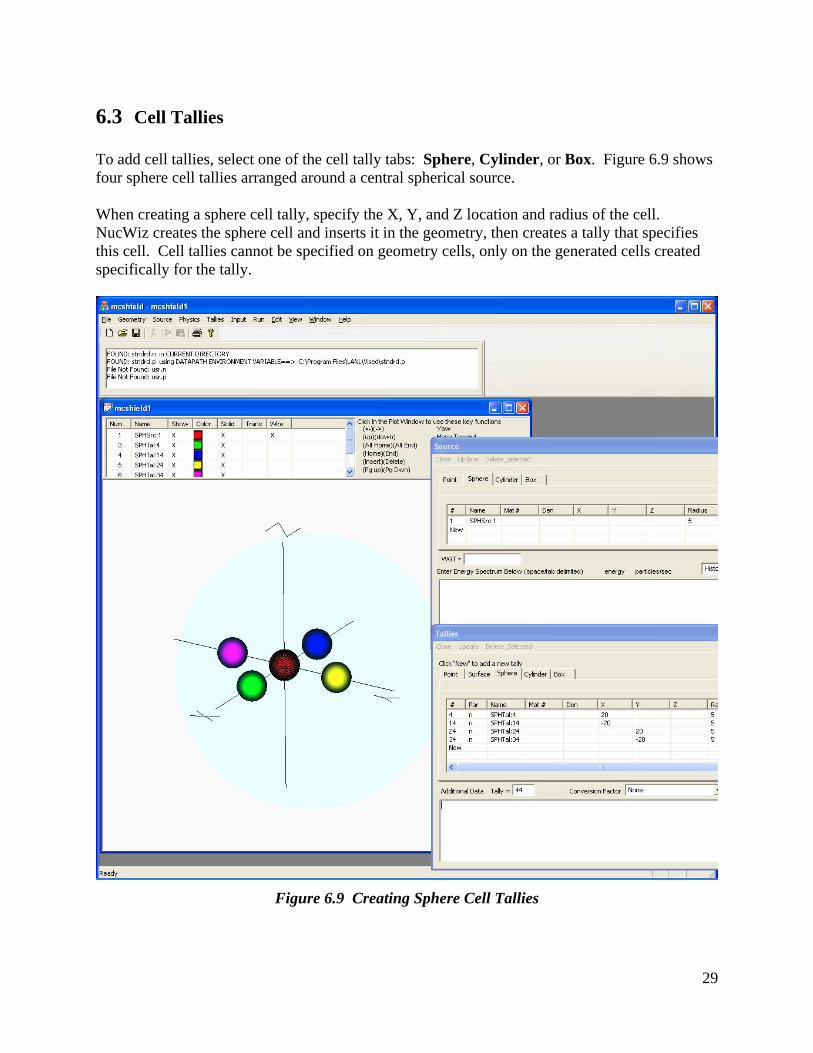
6.3 Cell Tallies To add cell tallies, select one of the cell tally tabs: Sphere, Cylinder, or Box. Figure 6.9 shows four sphere cell tallies arranged around a central spherical source. When creating a sphere cell tally, specify the X, Y, and Z location and radius of the cell. NucWiz creates the sphere cell and inserts it in the geometry, then creates a tally that specifies this cell. Cell tallies cannot be specified on geometry cells, only on the generated cells created specifically for the tally.
Figure 6.9 Creating Sphere Cell Tallies
30
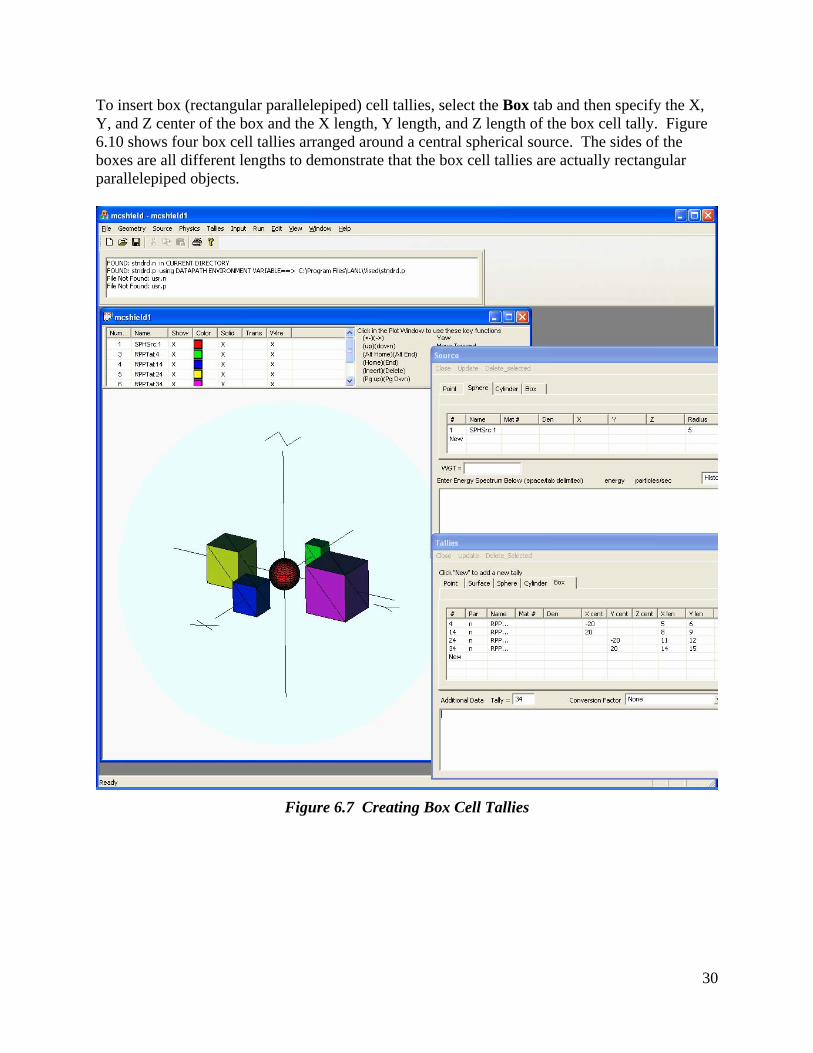
To insert box (rectangular parallelepiped) cell tallies, select the Box tab and then specify the X, Y, and Z center of the box and the X length, Y length, and Z length of the box cell tally. Figure 6.10 shows four box cell tallies arranged around a central spherical source. The sides of the boxes are all different lengths to demonstrate that the box cell tallies are actually rectangular parallelepiped objects.
Figure 6.7 Creating Box Cell Tallies
31
7 The Input File and Inserting Additional User Data The NucWiz input file can be displayed by selecting Input from the main menu. The generated input file includes all elements that have been created. Because NucWiz completely controls the creation of the input file, the user is not allowed to modify the input file. Instead, the user must bring up the appropriate NucWiz window to modify the element and then select Update to change the input file. NucWiz will not support all of the user data options. To accommodate user data not supported by NucWiz, the user can enter additional data information in the Additional User Data portion at the bottom of the Input window. Any valid MCNP text can be typed in this window. The current release of NucWiz does not check to see if the data entered contains valid MCNP input commands, so the user must be careful in validating the information that is entered in this window. Anything typed in this window will automatically be appended to the user input file in the upper portion of the Input window. Additional user data that should be entered here include at least a “ctme” or “nps” line to terminate the run. Additional data might include “print” statements or “phys” control cards. When the user saves a file in NucWiz, all of this supporting text is also written to the NucWiz file that can be read in and modified at a later date. This file is not an MCNP file but a list of NucWiz objects.
32
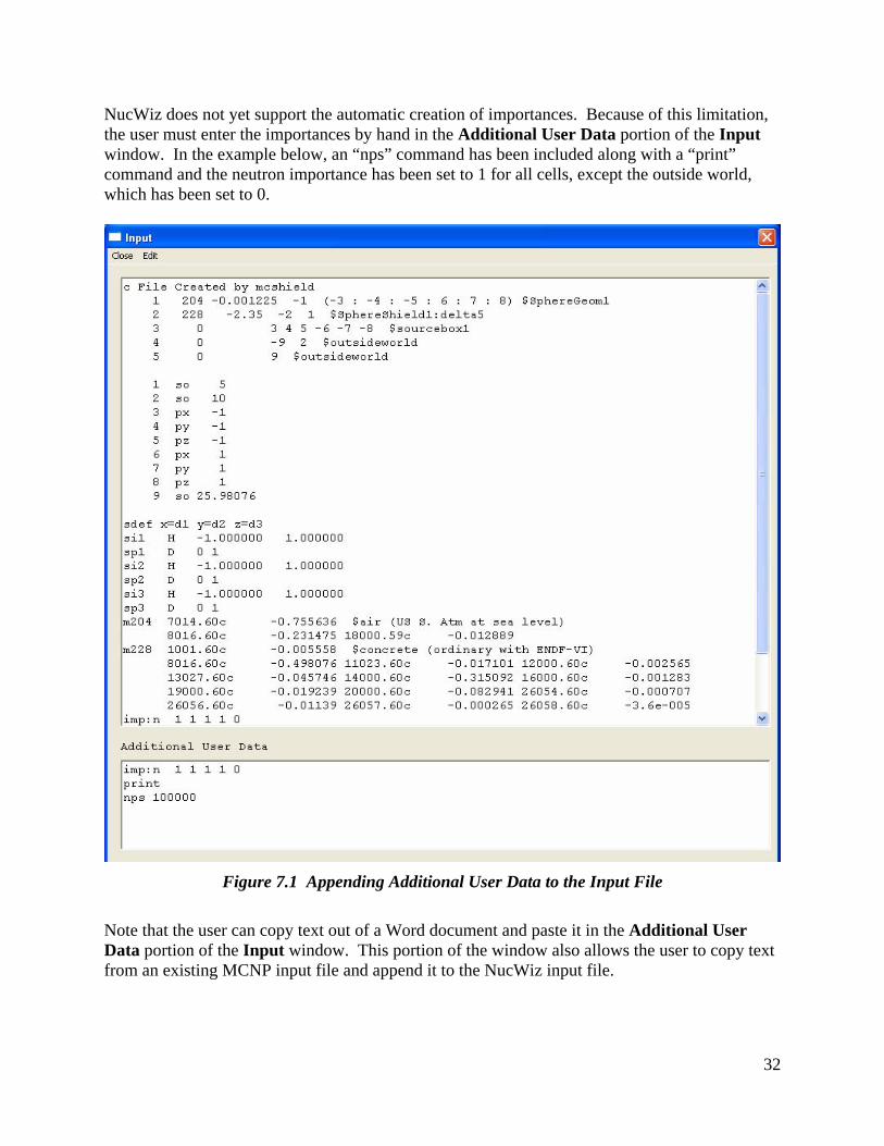
NucWiz does not yet support the automatic creation of importances. Because of this limitation, the user must enter the importances by hand in the Additional User Data portion of the Input window. In the example below, an “nps” command has been included along with a “print” command and the neutron importance has been set to 1 for all cells, except the outside world, which has been set to 0.
Figure 7.1 Appending Additional User Data to the Input File
Note that the user can copy text out of a Word document and paste it in the Additional User Data portion of the Input window. This portion of the window also allows the user to copy text from an existing MCNP input file and append it to the NucWiz input file.
33
8 NucWiz Plot Options NucWiz implements DirectX© for all geometry visualization. DirectX comprises the graphics libraries developed by Microsoft for three-dimensional geometry visualization. NucWiz is designed using the DirectX 9.0c libraries, allowing for backwards compatibility with the Windows XP© operating system. Higher library versions only work with Windows Vista© and Windows 7©. To use NucWiz, the user must install the DirectX 9.0c End-User Runtime libraries from the Microsoft website: http://www.microsoft.com/downloads/details.aspx?displaylang=en&FamilyID=2da43d38-db71-4c1b-bc6a-9b6652cd92a3 Using the DirectX graphics libraries allows NucWiz to take advantage of state-of-the-art graphics capabilities and potentially the hardware acceleration available for DirectX applications. With this initial implementation, only spheres, boxes, and cylinders are supported. These objects are standard graphics objects that can be created by DirectX. Additionally, DirectX has functions for the many vector calculations required for three-dimensional visualization applications. By default, NucWiz will show a three-dimensional perspective of the geometry. On the right side of the plot window is a pull-down menu that allows the user to change the view basis to the six orthogonal views along with an isometric view, identified as XYZ. The right side of the plot also has an Axis toggle that allows the user to turn on and off the display of the axis.
34
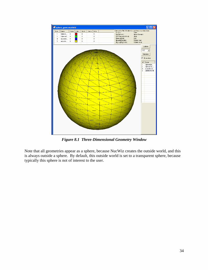
Figure 8.1 Three-Dimensional Geometry Window
Note that all geometries appear as a sphere, because NucWiz creates the outside world, and this is always outside a sphere. By default, this outside world is set to a transparent sphere, because typically this sphere is not of interest to the user.
35
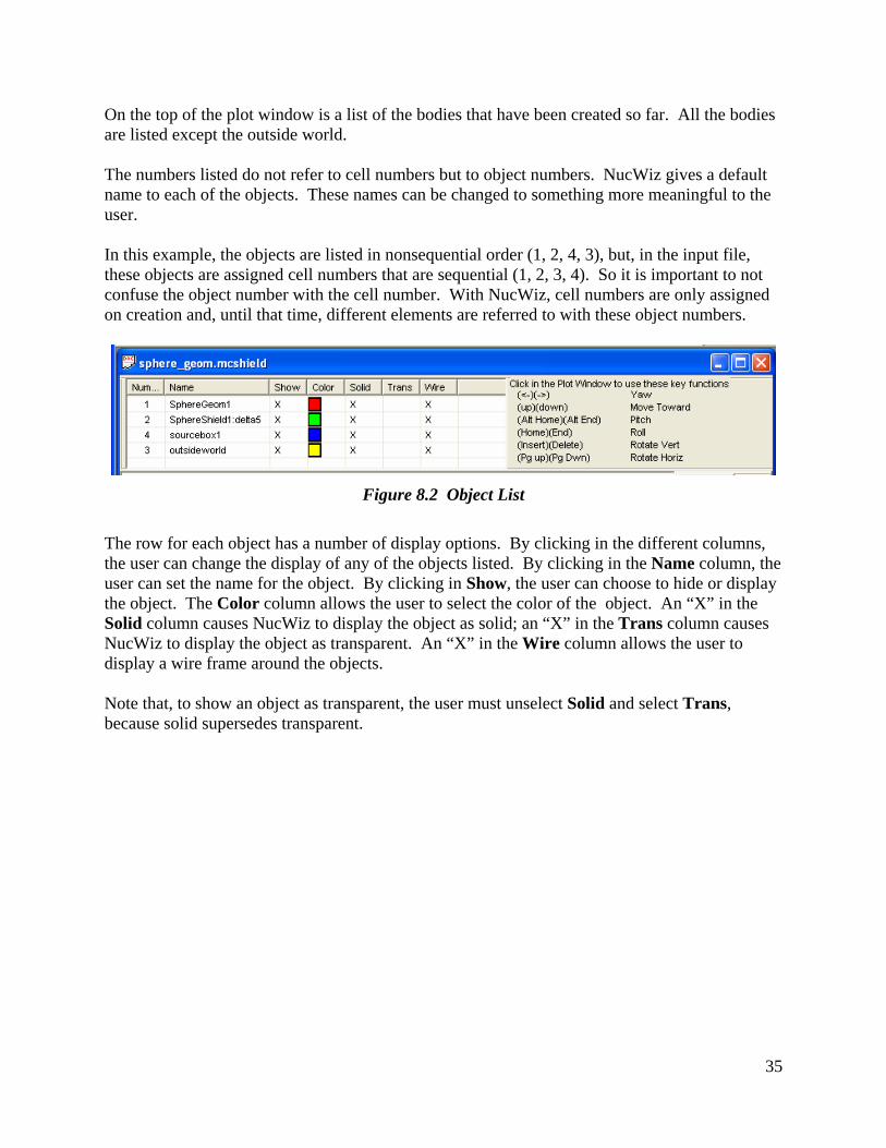
On the top of the plot window is a list of the bodies that have been created so far. All the bodies are listed except the outside world. The numbers listed do not refer to cell numbers but to object numbers. NucWiz gives a default name to each of the objects. These names can be changed to something more meaningful to the user. In this example, the objects are listed in nonsequential order (1, 2, 4, 3), but, in the input file, these objects are assigned cell numbers that are sequential (1, 2, 3, 4). So it is important to not confuse the object number with the cell number. With NucWiz, cell numbers are only assigned on creation and, until that time, different elements are referred to with these object numbers.
Figure 8.2 Object List
The row for each object has a number of display options. By clicking in the different columns, the user can change the display of any of the objects listed. By clicking in the Name column, the user can set the name for the object. By clicking in Show, the user can choose to hide or display the object. The Color column allows the user to select the color of the object. An “X” in the Solid column causes NucWiz to display the object as solid; an “X” in the Trans column causes NucWiz to display the object as transparent. An “X” in the Wire column allows the user to display a wire frame around the objects. Note that, to show an object as transparent, the user must unselect Solid and select Trans, because solid supersedes transparent.
36
In this example, to hide the outside world sphere, the user would remove the “X” in the Show column on object 3 (by clicking in that colum). To make the shield cells (objects 1 and 2) transparent, the use would turn off Solid and turn on Trans by clicking in the appropriate columns. The resulting geometry plot is shown below:
Figure 8.3 Wire Frame Geometry Display
37
The isometric view of the geometry can be changed to a cross-sectional view by selecting the appropriate basis view in the pull down menu on the right under Update. Shown below is an XY view of this geometry that can be displayed by selecting the XY option in the pull down menu.
Figure 8.4 Cross-Sectional View of the Geometry
38
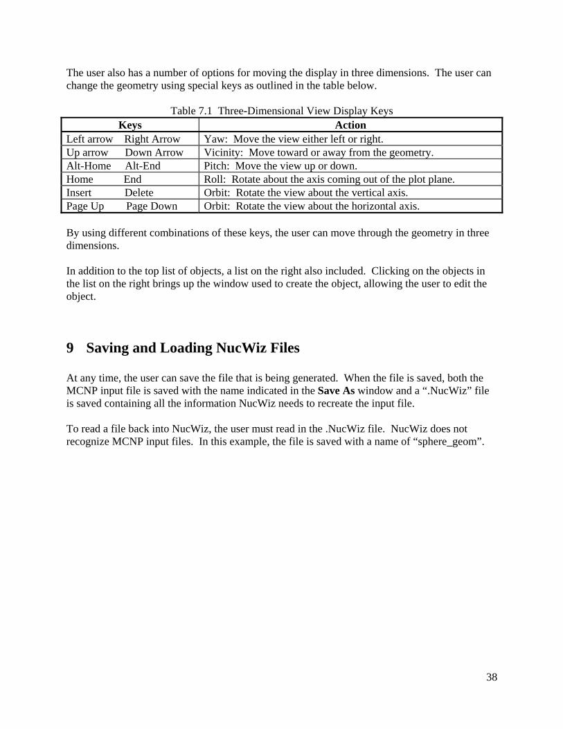
The user also has a number of options for moving the display in three dimensions. The user can change the geometry using special keys as outlined in the table below.
Table 7.1 Three-Dimensional View Display Keys Keys Action
Left arrow Right Arrow Yaw: Move the view either left or right. Up arrow Down Arrow Vicinity: Move toward or away from the geometry. Alt-Home Alt-End Pitch: Move the view up or down. Home End Roll: Rotate about the axis coming out of the plot plane. Insert Delete Orbit: Rotate the view about the vertical axis. Page Up Page Down Orbit: Rotate the view about the horizontal axis. By using different combinations of these keys, the user can move through the geometry in three dimensions. In addition to the top list of objects, a list on the right also included. Clicking on the objects in the list on the right brings up the window used to create the object, allowing the user to edit the object.
9 Saving and Loading NucWiz Files At any time, the user can save the file that is being generated. When the file is saved, both the MCNP input file is saved with the name indicated in the Save As window and a “.NucWiz” file is saved containing all the information NucWiz needs to recreate the input file. To read a file back into NucWiz, the user must read in the .NucWiz file. NucWiz does not recognize MCNP input files. In this example, the file is saved with a name of “sphere_geom”.
39
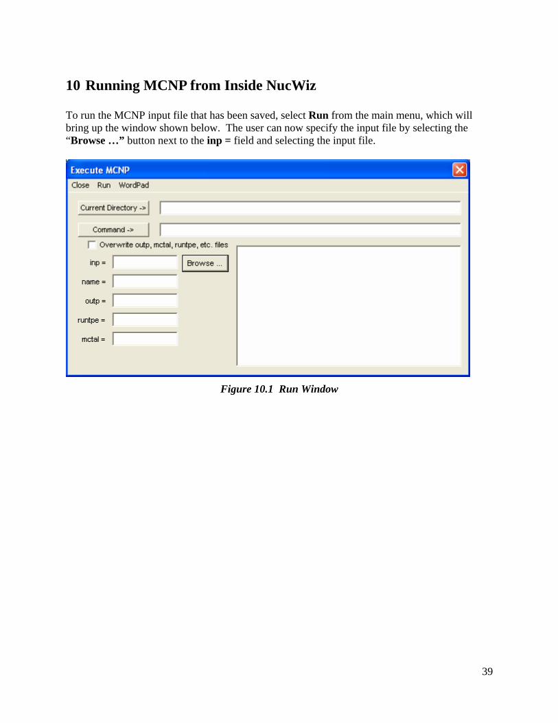
10 Running MCNP from Inside NucWiz To run the MCNP input file that has been saved, select Run from the main menu, which will bring up the window shown below. The user can now specify the input file by selecting the “Browse …” button next to the inp = field and selecting the input file.
Figure 10.1 Run Window
40
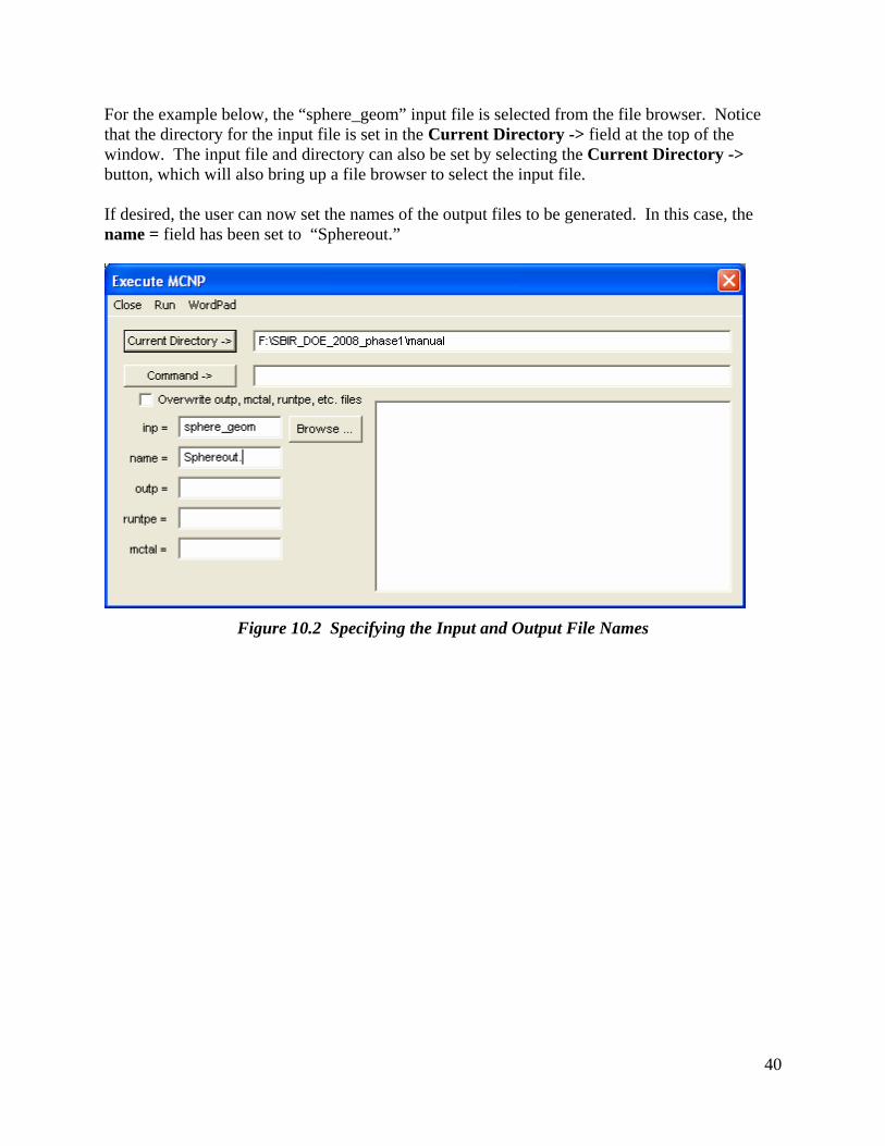
For the example below, the “sphere_geom” input file is selected from the file browser. Notice that the directory for the input file is set in the Current Directory -> field at the top of the window. The input file and directory can also be set by selecting the Current Directory -> button, which will also bring up a file browser to select the input file. If desired, the user can now set the names of the output files to be generated. In this case, the name = field has been set to “Sphereout.”
Figure 10.2 Specifying the Input and Output File Names
41
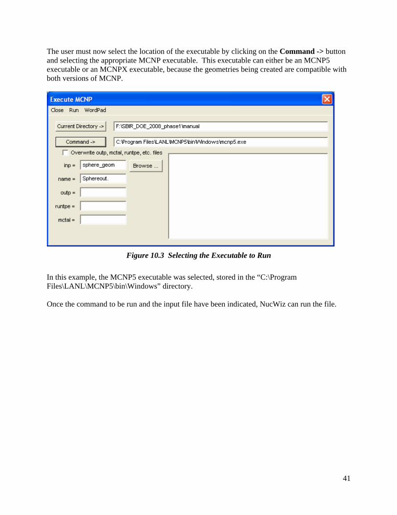
The user must now select the location of the executable by clicking on the Command -> button and selecting the appropriate MCNP executable. This executable can either be an MCNP5 executable or an MCNPX executable, because the geometries being created are compatible with both versions of MCNP.
Figure 10.3 Selecting the Executable to Run
In this example, the MCNP5 executable was selected, stored in the “C:\Program Files\LANL\MCNP5\bin\Windows” directory. Once the command to be run and the input file have been indicated, NucWiz can run the file.
42
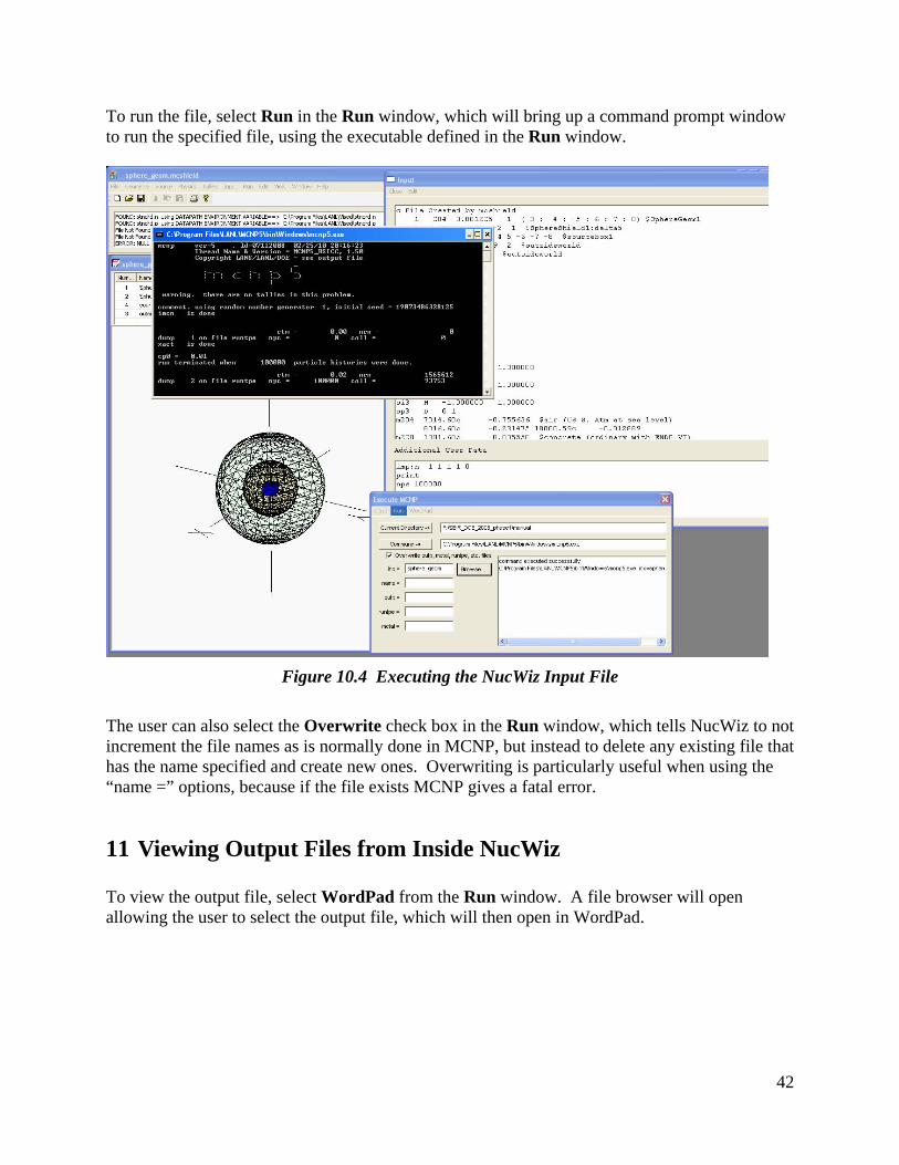
To run the file, select Run in the Run window, which will bring up a command prompt window to run the specified file, using the executable defined in the Run window.
Figure 10.4 Executing the NucWiz Input File
The user can also select the Overwrite check box in the Run window, which tells NucWiz to not increment the file names as is normally done in MCNP, but instead to delete any existing file that has the name specified and create new ones. Overwriting is particularly useful when using the “name =” options, because if the file exists MCNP gives a fatal error.
11 Viewing Output Files from Inside NucWiz To view the output file, select WordPad from the Run window. A file browser will open allowing the user to select the output file, which will then open in WordPad.
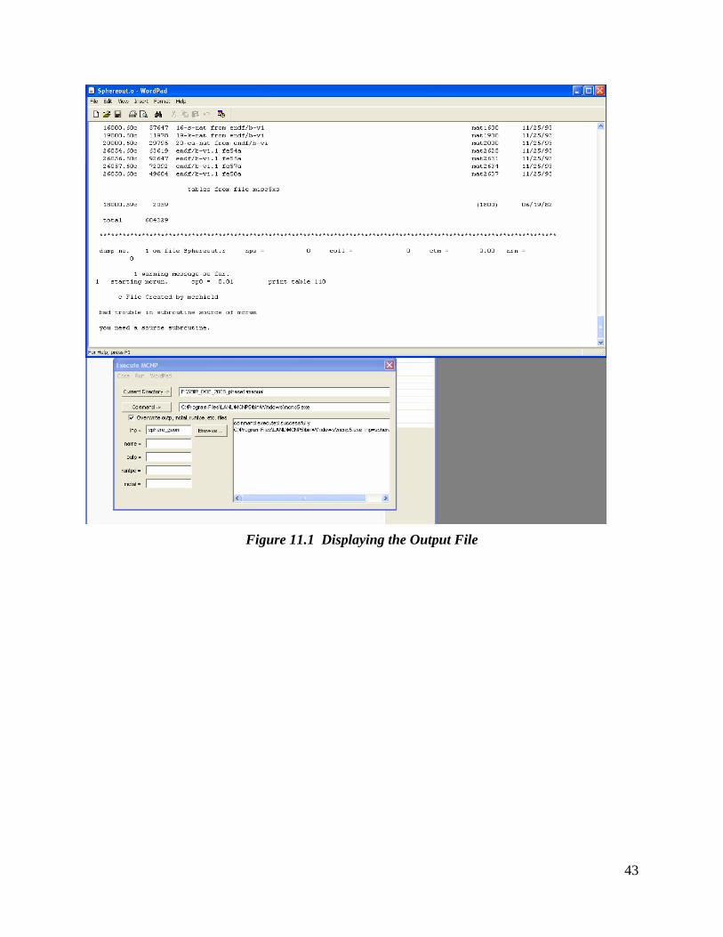
43
Figure 11.1 Displaying the Output File