Graphene Composite Fin (GCFTM)Technology Advanced Energy ...
19
WORLD CLASS ENGINEERING AND PROTOTYPING SOLUTIONS Graphene Composite Fin (GCF TM )Technology – Advanced Energy Storage Thermal Management General Information James Piñón President [email protected] September 6, 2016 - P_v6.0 Hybrid Design Services, Inc. 2479 Elliott Drive Troy, MI 48083 248-298-3400
Transcript of Graphene Composite Fin (GCFTM)Technology Advanced Energy ...

WORLD CLASS ENGINEERING AND PROTOTYPING SOLUTIONS
Graphene Composite Fin (GCFTM)Technology –Advanced Energy Storage Thermal Management
General Information
James Piñó[email protected]
September 6, 2016 - P_v6.0
Hybrid Design Services, Inc.2479 Elliott Drive
Troy, MI 48083248-298-3400

WORLD CLASS ENGINEERING AND PROTOTYPING SOLUTIONS
HDS Graphene Composite Fin (GCFTM)Tech Summary
– Patent-pending Technology
– Outperforms thermal performance of passive Al or Cu plates
– Offers thermal performance similar to complex liquid cooling systems
– Reduced Size, Weight, and Power Consumption (SWaP)
– Is lightweight and non-corrosive
– Is easy to manufacture and assemble
2

WORLD CLASS ENGINEERING AND PROTOTYPING SOLUTIONS
Graphene Nanoplatelets
HDS designs use a domestically-sourced, low-cost graphene nanoplatelet material,manufactured via a non-oxidizing process to produce an exceptionally pure materialwhose size, shape & edge chemistry can be controlled to customize properties.
The graphene nanoplatelet materials are laminated, bonded, or mixed with otherbase materials to provide the required thermal and structural performance.
3
Graphene and Nano Carbon Materials

WORLD CLASS ENGINEERING AND PROTOTYPING SOLUTIONS
Graphene Composite Fin (GCFTM) - Competitive Positioning - I
GCFTM vs graphite foil:
– Better electrical or thermal properties
– Tailored compositions consisting of graphene nanoplatelets
– Can include selected additives or coatings designed for specific properties
– Better two-dimensional anisotropic properties
GCFTM vs metal foil:
– Lighter
– Does not corrode
– Better thermal properties
– Much better two-dimensional anisotropic properties
– Tailored wettability and chemical resistance
4
Product DescriptionIn-plane Thermal
Conductivity (W/mK)
Graphene used in GCFTM
Anisotropic – controlled heat transfer in 2DTailored wettability and chemical resistance
> 500
GCFTM
Anisotropic – controlled heat transfer in 3DTailored thickness, strength, physical, thermal, and electrical properties
300-475
Natural Graphite Limited thermal conductivity 150 – 400
Copper Lower thermal conductivity, heavy < 400
Aluminum Much lower thermal conductivity, corrosive < 240

WORLD CLASS ENGINEERING AND PROTOTYPING SOLUTIONS
HDS GCFTM – Competitive Positioning - II
HOPG
Pri
ce
In-Plane Thermal Conductivity, W/mK
200 400 600 800 1,000 1,200
Al, Cu
PG
GraphiteGCF
Price vs.Performance
Thickness vs.Performance
5
HOPGTh
ickn
ess
(mm
)Al, Cu
GCF
100
200
400
500 +
Graphite
300
In-Plane Thermal Conductivity, W/mK
200 400 600 800 1,000 1,200
HOPG has high conductivity, but is also brittle
WORLD CLASS ENGINEERING AND PROTOTYPING SOLUTIONS
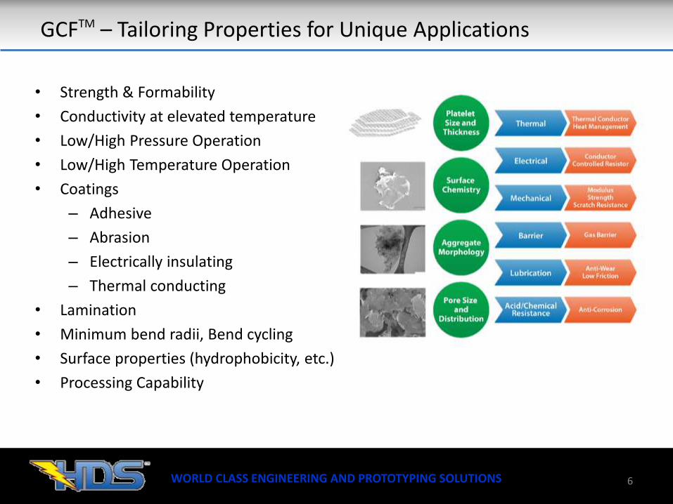
GCFTM – Tailoring Properties for Unique Applications
• Strength & Formability
• Conductivity at elevated temperature
• Low/High Pressure Operation
• Low/High Temperature Operation
• Coatings
– Adhesive
– Abrasion
– Electrically insulating
– Thermal conducting
• Lamination
• Minimum bend radii, Bend cycling
• Surface properties (hydrophobicity, etc.)
• Processing Capability
6

WORLD CLASS ENGINEERING AND PROTOTYPING SOLUTIONS 7
GCFTM Energy Storage Example

WORLD CLASS ENGINEERING AND PROTOTYPING SOLUTIONS
Energy Storage Thermal Management Overview (transportation)
8
Active Thermal Management Solutions
Liquid
Air
Cooling Tube
Flow thru Fin
Cold Plate
External
Cabin
External w/ AC
Performance Cost
HDS Graphene Composite Fin (HDS GCFTM)
Typical HEV
Typical PHEV / EV

WORLD CLASS ENGINEERING AND PROTOTYPING SOLUTIONS
HDS Graphene Composite Fin* (GCFTM)
9
Al Cooling Tube
HDS Graphene Composite Fin (GCFTM)
Compression Foam
Cell Frame
Pouch Cell
Module
Graphene Composite Fin* Advantages
Reduced parasitic energy consumption
Fewer Fluid leak points
Lower Complexity & parts count
Lower System Cost
* Patent-pending
Current industry designs utilize circulating liquid which passes through a series of internal heat exchangers in the battery modules. Each ‘fin’ requires multiple seals/gaskets.
FROM: TO:

WORLD CLASS ENGINEERING AND PROTOTYPING SOLUTIONS 10
Cell Temp Rise ~ 2.6°C (spot) / 2.3°C (area)*
* Source: Variable Fidelity Methodology For Thermal Battery Modeling H.Lewis, B.Zandi, G.Lewis, & S.Ketkar 3.7W/cell 10L/min 30° C Inlet Temp
Gen II GCF Comparison to Flow through Fin
Comparable cooling performance (less than 3 deg. C rise) while improving:
Manufacturing part count Complexity Leak paths (>500 O-rings ~ 12),
Pressure drop/ pumping losses on the 12Vdc system
Cell Temp Rise ~ 2.0°C
GCFTM – Gen II Simulation Results

WORLD CLASS ENGINEERING AND PROTOTYPING SOLUTIONS 11
Gen II and Gen III GCF testing Underway
Gen II GCF Testing shows very good correlation with simulation results.
GCFTM – Gen II Test Results
Test Results = 476 W/m-K

WORLD CLASS ENGINEERING AND PROTOTYPING SOLUTIONS
HDS GCFTM – Gen III Designs: Pouch, Prismatic, & Cylindrical Cells
12
Source: Siemens, NASA, FIA Formula E, FedEx, Airbus

WORLD CLASS ENGINEERING AND PROTOTYPING SOLUTIONS
HDS GCFTM Summary
HDS Graphene Composite Fin Technology
– Outperforms thermal performance of passive Al or Cu plates
– Offers thermal performance similar to complex liquid cooling systems
– Reduced Size, Weight, and Power Consumption (SWaP)
– Provides superior heat spreading/distribution performance
– Is lightweight and non-corrosive
– Offers adjustable thicknesses and structural performance
– Offers reduced coolant pumping power, leak paths, and parts count
– Offers new design flexibility for thermal management system optimization
– Is easy to manufacture and assemble
13

WORLD CLASS ENGINEERING AND PROTOTYPING SOLUTIONS 14
About HDS

WORLD CLASS ENGINEERING AND PROTOTYPING SOLUTIONS
HDS Corporate Introduction
15

WORLD CLASS ENGINEERING AND PROTOTYPING SOLUTIONS
HDS Design, Engineering, Prototyping, & Testing Services
16
• Complete Vehicle xEV Drive Design, Development, Vehicle Integration, and Testing• Heavy-duty, Off-road, Marine, & Military Systems• Renewable Energy & Stationary Systems
Passenger & Cargo Vehicle Drive Systems Heavy-duty Systems Renewable Energy & Stationary Systems
Testing and Simulation Services

WORLD CLASS ENGINEERING AND PROTOTYPING SOLUTIONS
HDS Energy Storage Design & Engineering Expertise
17
Module Design and Optimization• Cell Selection
• Module Packaging
• Cell carrier and Interconnect strategy
• Module V/T sense
• Thermal System Integration
Thermal and Structural Analyses• Cell Thermal Model Correlation
• Module model development and correlation
• Module and Pack Thermal strategy development
• Module and Pack Structural System Design
Development, Design, and Prototyping
Prototype Development• Module Builds
• Pack Builds
• Incoming and End-of-line testing
• Supplier Management
Pack Design and Optimization• Module Size and configuration optimization
• Pack Electrical, Mechanical and Thermal Interface
• Vehicle Packaging & Environmental Protection
• BMS Development and Integration

WORLD CLASS ENGINEERING AND PROTOTYPING SOLUTIONS
OTS Battery Management Systems
HV Sense Boards
‘Smart’ Power Distribution Systems
HDS Products & IP
EV and HEV Conversion Systems
Graphene Composite Fins

WORLD CLASS ENGINEERING AND PROTOTYPING SOLUTIONS 19
James PiñónPresident [email protected]
(313) 673-6917
Please contact HDS to learn more!
Hybrid Design Services, Inc.2479 Elliott Dr.Troy, MI 48083 – USA(248) 298-3400
www.HybridDesignServices.com