GRAITEC ADVANCED TUTORIALS · GRAITEC ADVANCED TUTORIALS 5 GRAITEC Tutorial – Design Groups The...
20
TUTORIALS 2018 Design Groups
Transcript of GRAITEC ADVANCED TUTORIALS · GRAITEC ADVANCED TUTORIALS 5 GRAITEC Tutorial – Design Groups The...

TUTORIALS 2018
Design Groups
About GRAITEC Tutorials GRAITEC technology evolution is driven by years of practical experience and combined with user feedback to provide the most intelligent and effective structural, BIM and design workflows possible.
GRAITEC Tutorials are provided as a free resource designed to guide users in the best practice methods of applying GRAITEC software, add-ons and industry solutions to speed up, enhance or automate everyday process.
GRAITEC Tutorials are written as illustrated step by step walk-throughs and assume a certain level of industry experience in the given subject matter or know-how with the related Autodesk software.
GRAITEC ADVANCED TUTORIALS
3
TABLE OF CONTENTS
GRAITEC TUTORIAL – DESIGN GROUPS ................................................................................................... 5
DESIGN GROUPS ............................................................................................................................................................ 5 Purpose .............................................................................................................................................................. 5
REVIT ............................................................................................................................................................................. 6 Workflow ............................................................................................................................................................. 6 Calculation .......................................................................................................................................................... 8 Output ............................................................................................................................................................... 11 Management ..................................................................................................................................................... 12
ADVANCE DESIGN ......................................................................................................................................................... 14 Concept ............................................................................................................................................................ 14 Workflow ........................................................................................................................................................... 14 Additional settings ............................................................................................................................................ 16
INTEROPERABILITY ........................................................................................................................................................ 17
USEFUL LINKS AND INFORMATION ................................................................................................................................... 18
PRODUCTS FEATURED IN GRAITEC TUTORIALS ............................................................................................................. 18 Add-ons ............................................................................................................................................................ 18 Industry Solutions ............................................................................................................................................. 18 Products ........................................................................................................................................................... 18

GRAITEC ADVANCED TUTORIALS
5
GRAITEC Tutorial – Design Groups The aim of this tutorial is to introduce users to the concept of design groups, used in Advance BIM Designers in Revit, as well as in Advance Design.
Design Groups
Construction engineers often deal with large project sites, where they need to calculate and reinforce hundreds of structural elements. In these situations, to simplify the process slightly, both from the site engineer and the material and bar schedules management point of view, elements are built with the same section properties, as part of a group.
By taking into account the state of efforts for all the group elements, a single reinforcement cage type is obtained and placed in the formwork. This makes it possible to deal with less reinforcement bar lengths and bar shapes.
In the design process, this result can be achieved using the “Design Group” concept in the Reinforced Concrete BIM Designers working on the Autodesk Revit or Advance Design platform.
Purpose • Easy management of columns / foundations and their reinforcement details in groups, which saves time when
updating a project model.
• Producing identical 3D rebar cages for all grouped elements (hence, a single drawing sheet, but with a rebar schedule that takes into account all elements in the group).
• Defining the same geometry properties or material for all elements in a group, more precisely, having the possibility to assign the same parameters for a selection of elements;
• Detecting the Theoretical Reinforcement Envelope for a group of elements and generating a real reinforcement cage.
The concept applies to foundations and columns.
• Detecting the Theoretical Reinforcement Envelope for a group of elements and generating a real reinforcement cage
GRAITEC ADVANCED TUTORIALS
6
Revit
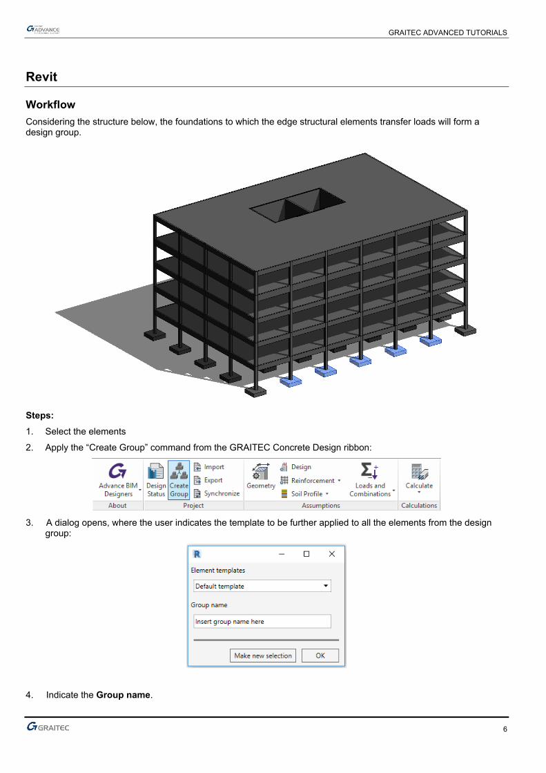
Workflow Considering the structure below, the foundations to which the edge structural elements transfer loads will form a design group.
Steps: 1. Select the elements
2. Apply the “Create Group” command from the GRAITEC Concrete Design ribbon:
3. A dialog opens, where the user indicates the template to be further applied to all the elements from the design
group:
4. Indicate the Group name.
GRAITEC ADVANCED TUTORIALS
7
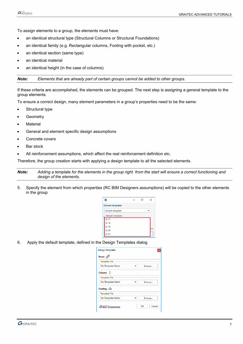
To assign elements to a group, the elements must have:
• an identical structural type (Structural Columns or Structural Foundations)
• an identical family (e.g. Rectangular columns, Footing with pocket, etc.)
• an identical section (same type)
• an identical material
• an identical height (in the case of columns)
Note: Elements that are already part of certain groups cannot be added to other groups.
If these criteria are accomplished, the elements can be grouped. The next step is assigning a general template to the group elements.
To ensure a correct design, many element parameters in a group’s properties need to be the same:
• Structural type
• Geometry
• Material
• General and element specific design assumptions
• Concrete covers
• Bar stock
• All reinforcement assumptions, which affect the real reinforcement definition etc.
Therefore, the group creation starts with applying a design template to all the selected elements.
Note: Adding a template for the elements in the group right from the start will ensure a correct functioning and design of the elements.
5. Specify the element from which properties (RC BIM Designers assumptions) will be copied to the other elements in the group
6. Apply the default template, defined in the Design Templates dialog
GRAITEC ADVANCED TUTORIALS
8
Calculation In this stage, a group is already created. Calculation is performed by selecting one of the elements in a group. If a single group element is selected and calculated, this action triggers the calculation process for the entire group (all the elements belonging to the group).
a) For Columns:
• Design calculation is done individually for each group element (internally, based on any existing FEM results imported from a third party software, or any efforts that were manually added by the user);
• After the calculation, the Theoretical Reinforcement Envelope (for longitudinal reinforcement) is obtained. The Theoretical Transverse Reinforcement Envelope is also obtained;
• The longitudinal reinforcement cage, based on the Theoretical Reinforcement Envelope, is obtained;
• Based on the Theoretical Transverse Reinforcement Envelope, the 3D longitudinal rebar cage and the conditions for transverse reinforcement according to the norm (the transverse reinforcement cage) is obtained;
• All elements in the group are reinforced in the same way (longitudinal reinforcement and transverse reinforcement).
b) For Foundations:
• The design is done internally for all group elements. The elements are reinforced with the biggest Theoretical Reinforcement Area found;
• In addition, the worst-case scenario Work Ratio for the geotechnical checks is retained as Group results. Based on these results, additional element adjustments are made to the elements in the group.
With the obtained Theoretical Reinforcement Envelope (based on any existing FEM results imported from a third party software, or any efforts that were manually added by the user), one of the elements is reinforced and further, this reinforcement cage is copied to all the other elements from the group
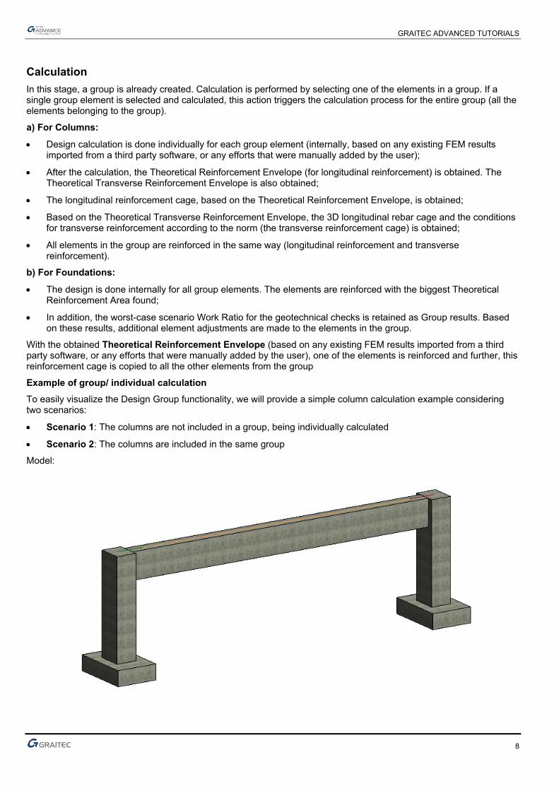
Example of group/ individual calculation To easily visualize the Design Group functionality, we will provide a simple column calculation example considering two scenarios:
• Scenario 1: The columns are not included in a group, being individually calculated
• Scenario 2: The columns are included in the same group
Model:
GRAITEC ADVANCED TUTORIALS
9
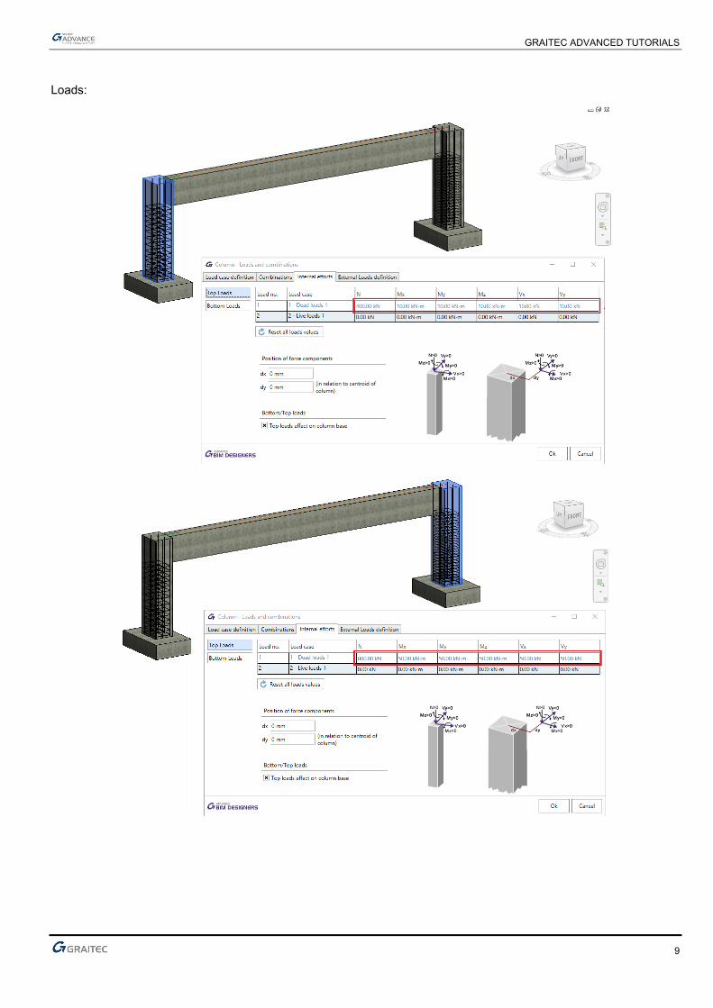
Loads:
GRAITEC ADVANCED TUTORIALS
10
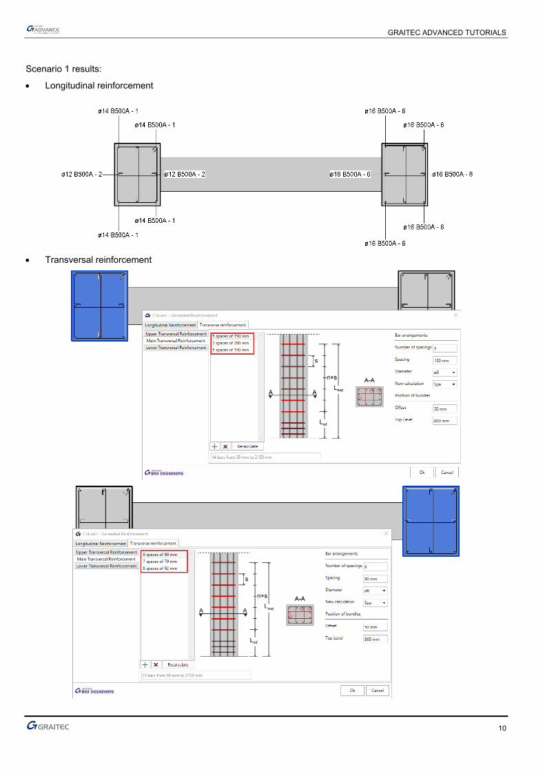
Scenario 1 results:
• Longitudinal reinforcement
• Transversal reinforcement
GRAITEC ADVANCED TUTORIALS
11
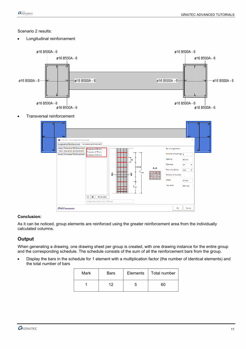
Scenario 2 results:
• Longitudinal reinforcement
• Transversal reinforcement
Conclusion: As it can be noticed, group elements are reinforced using the greater reinforcement area from the individually calculated columns.
Output When generating a drawing, one drawing sheet per group is created, with one drawing instance for the entire group and the corresponding schedule. The schedule consists of the sum of all the reinforcement bars from the group.
• Display the bars in the schedule for 1 element with a multiplication factor (the number of identical elements) and the total number of bars
Mark Bars Elements Total number
1 12 5 60
GRAITEC ADVANCED TUTORIALS
12
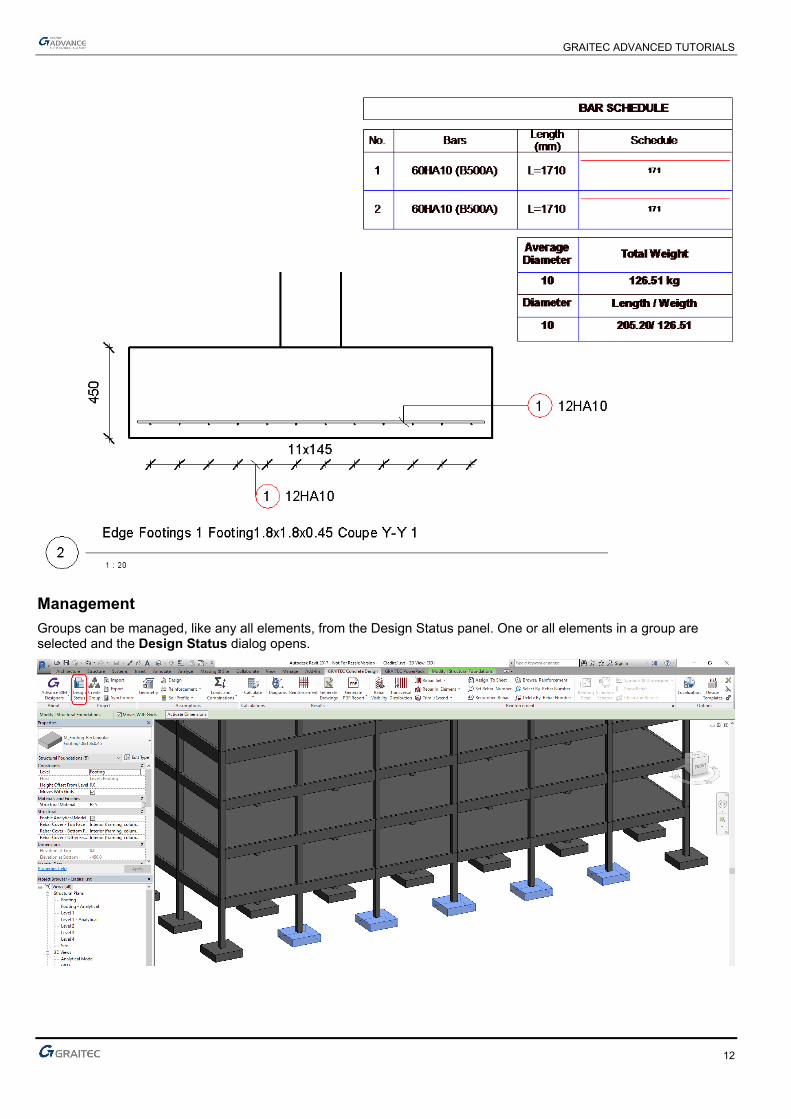
Management Groups can be managed, like any all elements, from the Design Status panel. One or all elements in a group are selected and the Design Status dialog opens.

GRAITEC ADVANCED TUTORIALS
13
1. The group can be recognized by the specific icon.
2. The type indicates the model category (Structural Columns or Structural Foundations) to which the group belongs.
3. The mark is actually the group name defined by the user.
4. The collapse button displays or hides the elements that are part of the group.
5. Add elements in group – includes additional elements in the already created group; when adding an element, the same verifications are made as when creating the group from scratch. Of course that all checks must be fulfilled for the footing/column to be included in the group.
Note: If the element does not observe the grouping criteria, a message is displayed to inform the user. If the criteria are observed, the group template will be applied to the new element added to the group.
6. Explode group – discards any group information and breaks a group object into its component objects, in order to design the element separately.
When modifying a geometric or design assumption for one of the group components, the change is applied to all elements in the design group.
GRAITEC ADVANCED TUTORIALS
14
Advance Design
Concept In Advance Design, the element design grouping is done using the Pilot Systems concept, which covers the current advantages of systems behavior: element drag and drop, selection of entire group, hide, isolate, etc.
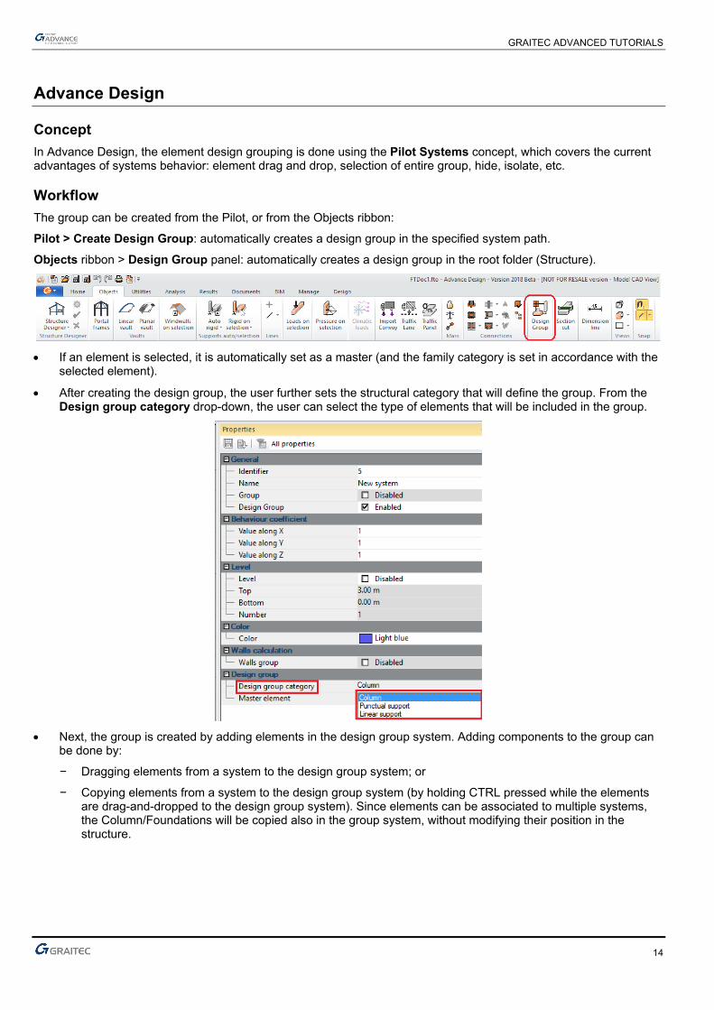
Workflow The group can be created from the Pilot, or from the Objects ribbon:
Pilot > Create Design Group: automatically creates a design group in the specified system path.
Objects ribbon > Design Group panel: automatically creates a design group in the root folder (Structure).
• If an element is selected, it is automatically set as a master (and the family category is set in accordance with the
selected element).
• After creating the design group, the user further sets the structural category that will define the group. From the Design group category drop-down, the user can select the type of elements that will be included in the group.
• Next, the group is created by adding elements in the design group system. Adding components to the group can
be done by:
− Dragging elements from a system to the design group system; or
− Copying elements from a system to the design group system (by holding CTRL pressed while the elements are drag-and-dropped to the design group system). Since elements can be associated to multiple systems, the Column/Foundations will be copied also in the group system, without modifying their position in the structure.
GRAITEC ADVANCED TUTORIALS
15
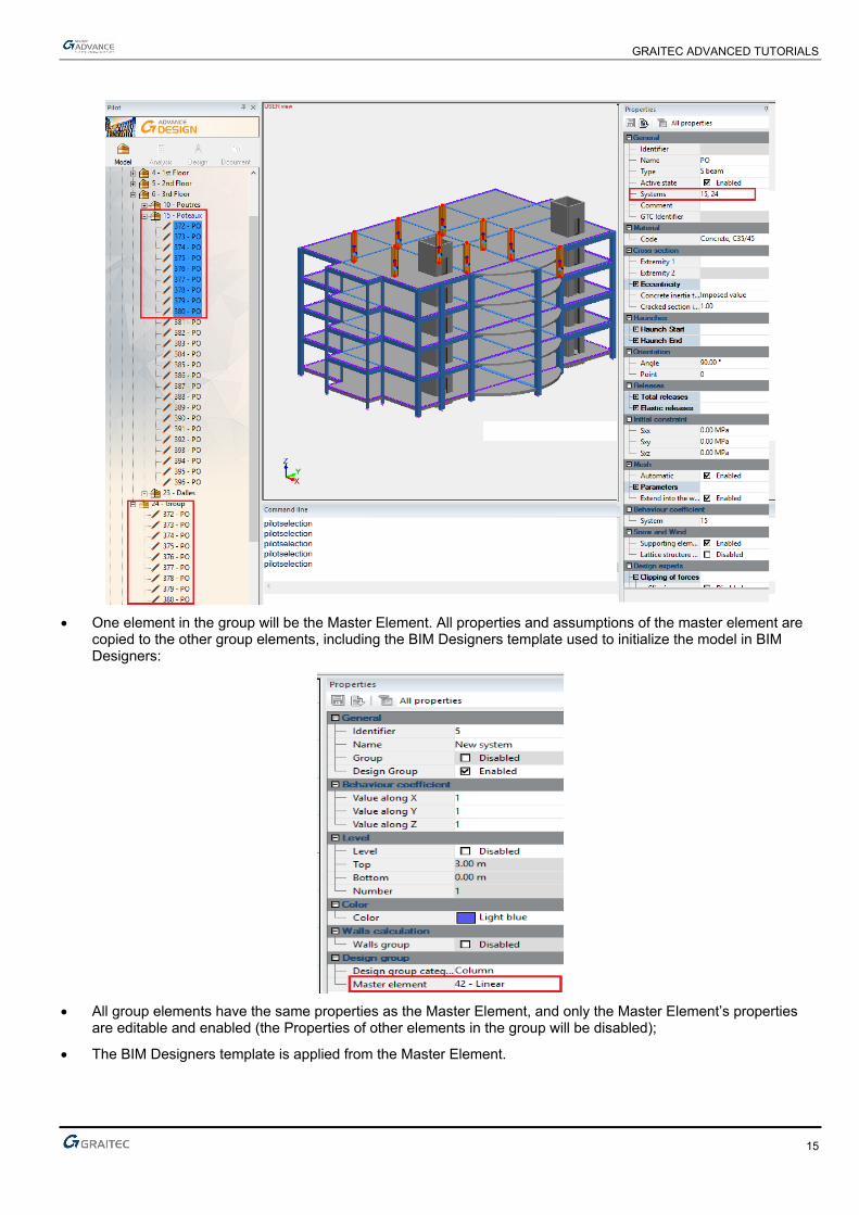
• One element in the group will be the Master Element. All properties and assumptions of the master element are
copied to the other group elements, including the BIM Designers template used to initialize the model in BIM Designers:
• All group elements have the same properties as the Master Element, and only the Master Element’s properties
are editable and enabled (the Properties of other elements in the group will be disabled);
• The BIM Designers template is applied from the Master Element.

GRAITEC ADVANCED TUTORIALS
16
Additional settings Adding elements in a group system can be performed:
• By using the system behavior (drag and drop from one system to another);
• By using the option in the Design group panel > Add elements in group: the selection is made directly in model (by window selection or pick point). After selection, the element IDs are listed in the edit field.
From the CAD point of view, the columns and linear supports (continuous foundations) will be available for modification (e.g., the user will be able to modify their height/length), but after the “Verify” calculation step, an error message will be displayed in the command bar, warning the user that the group is not homogenous.
GRAITEC ADVANCED TUTORIALS
17
Interoperability
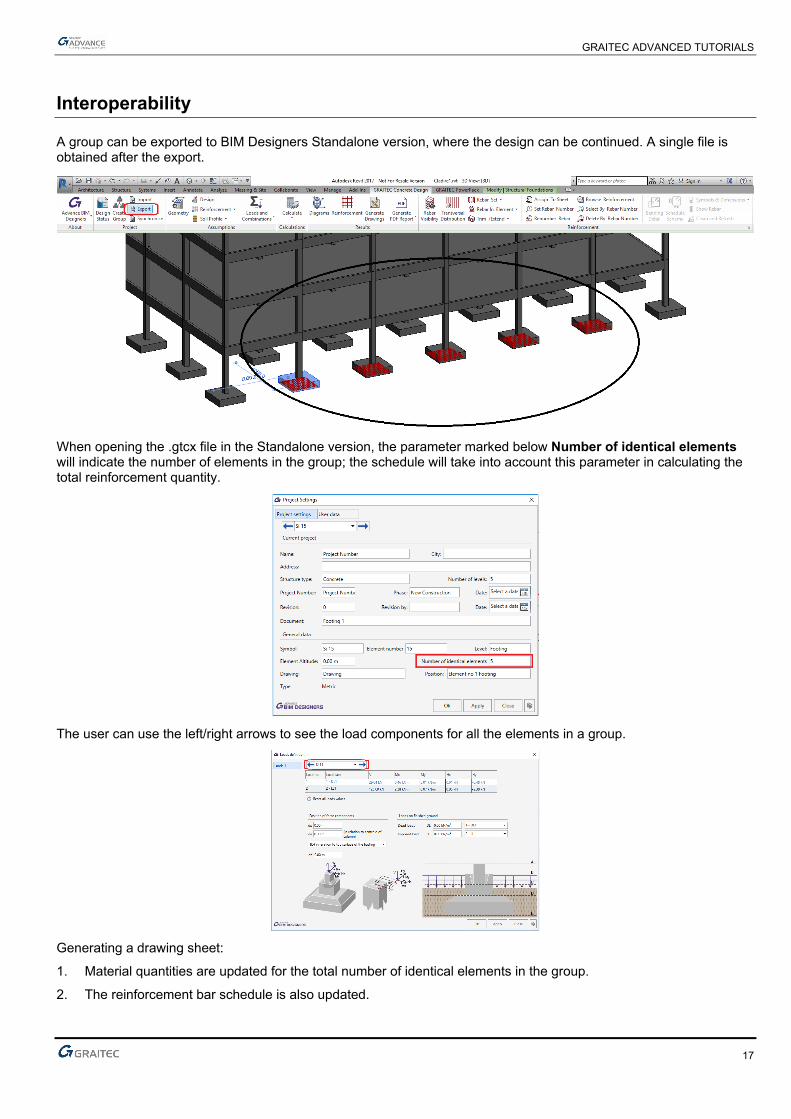
A group can be exported to BIM Designers Standalone version, where the design can be continued. A single file is obtained after the export.
When opening the .gtcx file in the Standalone version, the parameter marked below Number of identical elements will indicate the number of elements in the group; the schedule will take into account this parameter in calculating the total reinforcement quantity.
The user can use the left/right arrows to see the load components for all the elements in a group.
Generating a drawing sheet:
1. Material quantities are updated for the total number of identical elements in the group.
2. The reinforcement bar schedule is also updated.
GRAITEC ADVANCED TUTORIALS
18
Useful links and information
We hoped you enjoyed this tutorial. We welcome all feedback and new/improvement suggestions. To contact your nearest GRAITEC office or Partner, click here.
To download a free trial, read more information or purchase any product mentioned in this tutorial please visit Graitec Store.
Products featured in GRAITEC Tutorials
Add-ons PowerPack for Revit
Productivity add-on pack for Revit® with tools for Architectural, Structural and MEP Designers. PowerPack for Advance Steel
Productivity add-on pack for Autodesk® Advance Steel with a range of specific tools to boost capability, productivity and efficiency. BIM Connect for Revit Connected BIM workflows supporting advanced model and information synchronization and typical industry standards.
Industry Solutions Advance BIM Designers
A broad collection of advanced industry solutions for automating structural steel and concrete BIM and design-to-detail workflows. Stair & Railing Designer (Part of the Advance BIM Designers - Steel Series)
Fast and flexible stair and railing modelling ranges for Autodesk® Advance Steel. Steel Connection Designer (Part of the Advance BIM Designers - Steel Series)
Design steel connections to Euro Codes, US codes and Canadian codes directly in Advance Design or as a standalone solution. Reinforced Concrete BIM Designers (Part of the Advance BIM Designers - Concrete Series)
Design-driven reinforcement calculation and automated 3D modeling and documentation production for concrete columns, beams and footings.
Products Advance Design
Advanced finite element meshing and analysis for AEC projects delivering intelligent BIM connectivity and bi-directional links with Autodesk® Revit®.
Advance Workshop Advanced steel production management solution for steel fabricators needing to control, manage and automate project routing, tracking and production in mixed CNC machine, HMI and general workforce environments.
Advance Workshop DSTV Viewer Dedicated viewer for DSTV NC fabrication files with export capabilities.