Grain Refinement of Magnesium Alloy by Multiaxial Alternative
22
11 Grain Refinement of Magnesium Alloy by Multiaxial Alternative Forging and Hydrogenation Treatment Kunio Funami and Masafumi Noda Department of Mechanical Science and Engineering, Chiba Institute of Technology Japan 1. Introduction Owing to their high specific strength, magnesium alloys are promising materials for use in various structural products whose weight is to be minimized. These alloys are drawing attention as materials with reduced environmental load since they save both resources and energy. However, these alloys have low strength and a small number of slip systems and are more difficult to work forming. Therefore, it is necessary to modify them, e.g., improve the mechanical properties and fatigue strength of the alloys, and reduce processing costs, which would help increase their industrial applications. To overcome the above-mentioned drawbacks, the formation of a fine-grained structure would be useful. For magnesium materials, the effect of fine-grained structure on the static mechanical properties, fatigue, and fracture toughness has been investigated to study their practical applicability(Nagata et al,2007). Such investigations are very important for increasing the use of magnesium alloys as industrial materials (Noda et al, 2009). Microstructure control has been achieved through grain refinement by employing several strain work processes such as MA (Mechanical Alloying:Ameyama et al.,1998), ECAP (Equal Channel Angular Pressing:Berbon et al.,1999), ARB (Accumulative Roll-Bonding:Tsuji et al.,1999), and MAF (Multiaxial Alternative Forging:Noda et al.,2005 and Xing et al,2005). These methods were found to enhance strain energy in materials without changing their geometrical shapes. This means that under external deformation, it is necessary to produce in materials, as much as possible, a nonhomogeneous microstructure containing such as micro bands, shear bands, and lamellar boundaries. In the early stages of deformation, even a small increase in the number of dislocation pile-up sources influences the formation of dense dislocation walls and cells. Examples of such sources are static and dynamic recrystallization sources. Magnesium alloys have high hydrogen absorbing capacity, similar titanium alloys, and readily form hydrides under suitable temperature and pressure (Yoshimura et al, 1994). Hydride precipitates of MgH 2 obtained in this treatment were useful for developing high-density dislocation pile-up sources. This refinement treatment, which involves the use of hydrogen, titanium alloy, and titanium composite alloy with dispersed TiC particles, resulted in a homogeneous, fine, and equi-axial structure(Machida et al,2004). It appears that the combination of a plastic deformation process and hydrogenation treatment has considerable potential to induce a fine-grained structure in a magnesium alloy (Ishida et al, 2007). www.intechopen.com
Transcript of Grain Refinement of Magnesium Alloy by Multiaxial Alternative

11
Grain Refinement of Magnesium Alloy by Multiaxial Alternative Forging and
Hydrogenation Treatment
Kunio Funami and Masafumi Noda Department of Mechanical Science and Engineering, Chiba Institute of Technology
Japan
1. Introduction
Owing to their high specific strength, magnesium alloys are promising materials for use in
various structural products whose weight is to be minimized. These alloys are drawing
attention as materials with reduced environmental load since they save both resources and
energy. However, these alloys have low strength and a small number of slip systems and are
more difficult to work forming. Therefore, it is necessary to modify them, e.g., improve the
mechanical properties and fatigue strength of the alloys, and reduce processing costs, which
would help increase their industrial applications. To overcome the above-mentioned
drawbacks, the formation of a fine-grained structure would be useful. For magnesium
materials, the effect of fine-grained structure on the static mechanical properties, fatigue,
and fracture toughness has been investigated to study their practical applicability(Nagata et
al,2007). Such investigations are very important for increasing the use of magnesium alloys
as industrial materials (Noda et al, 2009).
Microstructure control has been achieved through grain refinement by employing several strain work processes such as MA (Mechanical Alloying:Ameyama et al.,1998), ECAP (Equal Channel Angular Pressing:Berbon et al.,1999), ARB (Accumulative Roll-Bonding:Tsuji et al.,1999), and MAF (Multiaxial Alternative Forging:Noda et al.,2005 and Xing et al,2005). These methods were found to enhance strain energy in materials without changing their geometrical shapes. This means that under external deformation, it is necessary to produce in materials, as much as possible, a nonhomogeneous microstructure containing such as micro bands, shear bands, and lamellar boundaries. In the early stages of deformation, even a small increase in the number of dislocation pile-up sources influences the formation of dense dislocation walls and cells. Examples of such sources are static and dynamic recrystallization sources. Magnesium alloys have high hydrogen absorbing capacity, similar titanium alloys, and readily form hydrides under suitable temperature and pressure (Yoshimura et al, 1994). Hydride precipitates of MgH2 obtained in this treatment were useful for developing high-density dislocation pile-up sources. This refinement treatment, which involves the use of hydrogen, titanium alloy, and titanium composite alloy with dispersed TiC particles, resulted in a homogeneous, fine, and equi-axial structure(Machida et al,2004). It appears that the combination of a plastic deformation process and hydrogenation treatment has considerable potential to induce a fine-grained structure in a magnesium alloy (Ishida et al, 2007).
www.intechopen.com
Magnesium Alloys - Design, Processing and Properties
246
In this study, we combined the hydrogen absorption method and the MAF process for grain refinement of a material surface. Hydrogenation treatment involves producing the hydride compound MgH2 in the magnesium alloy through hydrogen absorption, making use of magnesium’s ability to absorb hydrogen, and using the resultant hydrogen compounds to trap defects; these defects are induced by severe strain working such as shot peening on a material surface subjected to recrystallization and heat treatment for grain refinement. We study the effectiveness of hydrogenation treatment and the MAF process for grain refinement; we attempt to improve the strength of magnesium alloys by carrying out grain refining by the MAF process, investigate the mechanical properties of the grains, and improve the workability of these fine-grained materials. When hydrogenation-dehydrogenation and shot peening techniques are used, the surface structure of fine-grained magnesium materials obtained by MAF becomes finer. This study investigates the following: 1. effect of MAF on grain refinement in a magnesium alloy together with the
microstructure formation process of MAFed magnesium alloy and its mechanism 2. effect of hydrogenation treatment using rolling working and shot peening working for
plastic formation on the surface microstructure of the MAFed magnesium alloy 3. mechanical properties of a fine-grained magnesium alloy, that is, fatigue strength,
fracture toughness, and crack propagation behavior, and the influence of grain size on the properties.
2. Effect of grain refinement by multiaxial forging
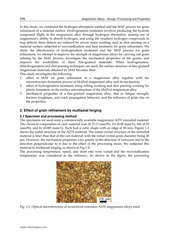
2.1 Specimen and processing method The specimens we used were a commercially available magnesium AZ31 extruded material. The chemical composition of each material was Al (3.13 mass%), Zn (0.90 mass%), Mn (0.55 mass%), and Fe (0.003 mass%). Each had a cubic shape with an edge of 30 mm. Figure 1-1 shows the initial structure of the AZ31 material. The initial crystal structure of the extruded material is finer than that of the cast material, with the initial crystal grain diameter being 20 μm. However, the mechanical properties vary greatly in the direction of extrusion and in the direction perpendicular to it due to the effect of the processing strain. We subjected this material to multiaxial forging, as shown in Fig.1-2. The processing temperature, speed, and draft rate were varied and the recrystallization temperature was considered as the reference. As shown in the figure, the processing
Fig. 1-1. Optical microstructure of as-received extrusion AZ31 magnesium alloys used.
www.intechopen.com

Grain Refinement of Magnesium Alloy by Multiaxial Alternative Forging and Hydrogenation Treatment
247
P
Rotation
90゜S.T.
L.T.L.
1
23
523 K
0.6 ks
523 K
0.6 ks3
1
2
21
3
P P
L.
L.T.S.T.
L.T.
L.S.T.
Rotation
90゜
P
Rotation
90゜S.T.
L.T.L.
1
23
523 K
0.6 ks
523 K
0.6 ks3
1
2
21
3
P P
L.
L.T.S.T.
L.T.
L.S.T.
Rotation
90゜
Fig. 1-2. Schematic illustration of the working process of the multi-axial alternative forging.
procedures comprised forging by alternately turning faces 1–3 by 90°. The execution of the forging process once for each of the faces was defined as one cycle. In any given cycle, forging was performed at a constant processing temperature, and the temperature was partially varied between cycles. For forging codition as shown in Fig.1-2, forging of the specimens was started after maintaining the specimens at 523 K for 3.6 ks. They were again maintained at the same temperature for 0.6 ks again before proceeding to process the next face. The temperature at which the specimens were maintained was 523 K for cycles 1 and 2, 473 K for cycles 3–5, and 443 K for cycles 6–8. The specimens were cooled in water after processing. The draft rate for each face was controlled at 20% and the displacement rate at 1 mm/min. The specimens were processed for eight cycles, which corresponded to an equivalent strain of 4.8. Direction S.T. was the direction of extrusion for the extruded material. The structures observation was made of the cast and extruded materials were observed after MAF processing, and the specimens were then subjected to the hardness test and tensile test. The dimensions of a specimen used for the tensile test were 1 mm (thickness), 3 mm (width), and 5 mm (length). The tensile test was conducted at room temperature and the initial strain rate was 8.3 × 10⁻³ s-1. The hardness test was conducted using the micro-Vickers method, with an indentation load of 2.94 N and a period of 30 s. The crystal grain diameter was observed using optical microscopy and SEM and calculated by the section method. The internal structure of the specimens was observed using TEM.
2.2 Structural changes and grain refinement by multiaxial forging 2.2.1 Multicycle forging of magnesium alloy The structure of a specimen forged for 6 cycles for the processing conditions shown in
Fig.1-2 is shown in Fig.1-3; the structure was observed using optical microscopy. Although
some coarse grains remain for both processing conditions, fine grains are found to be
dominant overall. While the average grain diameter for processing condition was about 1 μm.
Large plastic strain is accumulated internally in the specimen due to free forging. However,
strain distribution and accumulation in the material sides and section in contact with the
compression plate, as well as the internal strain distribution and accumulation were not
uniform.
Thus, the temperature of the material was not uniform when at which recrystallization
began was not uniform, leading to difference in the formation of fine crystal grains with
different sizes which are generated by dynamic recrystallization depending on the location
and the formation of different substructures resulting in different substructures at different
locations. However, uniform refinement became possible when the number of MAF
processing cycles was increased.
www.intechopen.com

Magnesium Alloys - Design, Processing and Properties
248
L.S
.T.
40 µmL.S
.T.
L.S
.T.
40 µm40 µm
Fig. 1-3. Optical microstructure of 6 cycles MAFed AZ31 magunesium alloys by working condition as shown in Fig.1-2.
20 µ m
(a ) (b )
(c ) (d )
20 µ m
(a ) (b )
(c ) (d )
Fig. 1-4. Optical microstructure of MAFed AZ31Mg alloys under various forging process, (a) : 1cycle,(b) : 2cycle,(c) :5cycle and (d) : 8cycle.
The number of cycles in forging processing condition and the changes in the specimen structure are shown in Fig.1-4. The initial grain diameter at the beginning of the processing cycle was 20 μm; the grain diameters at the end of the first, second, fifth, and eighth MAF processing cycles were 15, 9, 4, and 1 μm. Deformation bands and twin crystals were formed by one-pass processing, in which forging was conducted in the extruding direction and fine grains were formed by dynamic recrystallization, and the crystal grains that were elongated in the extruding direction were deformed in a perpendicular direction, which makes the crystal grains larger in the extrusion plane and smaller in the perpendicular plane. At the same time, a kink band is formed within the crystal grain in the perpendicular plane, which refines the grains even further. Similarly, in two-pass processing, twin crystals, deformation bands, and kink bands were formed on the three planes of extrusion planes and perpendicular plane, and they tended to be the cores that triggered dynamic recrystallization. That is, the effects of refinement by segmentation of crystal grains were small in both the extrusion plane and perpendicular plane for one-pass processing, highlighting the formation of fine grains around the ground boundary.
www.intechopen.com

Grain Refinement of Magnesium Alloy by Multiaxial Alternative Forging and Hydrogenation Treatment
249
Nu
mb
er o
f fr
acti
on
Nu
mb
er o
f fr
acti
on
Misorientation angle, θ /deg. Misorientation angle, θ /deg.
(a) (b)
Nu
mb
er o
f fr
acti
on
Nu
mb
er o
f fr
acti
on
Misorientation angle, θ /deg. Misorientation angle, θ /deg.
(a) (b)
Fig. 1-5. Misorientation angle distribution of MAFed AZ31Mg alloys by working condition as shown in Fig.1-2, (a):1cycle and (b):5cycle.
(a) (b) (c)
100 µm 20 µm 20 µm0001 2110
1010
(a) (b) (c)
100 µm100 µm 20 µm20 µm 20 µm20 µm0001 2110
1010
Fig. 1-6. IPF map of MAFed AZ31Mg alloys, (a):as-received extrusion material, (b): 1 cycle MAFed material, (c): 5 cycle MAFed material by forging working.
Further, crystal grains formed by refinement by segmentation were larger than fine grains formed around the grain boundary both in the extrusion plane and perpendicular plane in two-pass processing. Therefore, repeating this process in different directions, along the three axes, accelerates crystal grain refinement. The misorientation angle distribution diagram, and IPF map (Figs.1-5 and Fig.1-6) obtained from EBSP analysis support the above-mentioned facts. Figure 1-5 shows the frequency of orientation difference of the adjacent crystal. It is evident that the crystal grains become more uniform and refined as the number of MAF processing cycles is increased. Since the low-angle grain boundary with an orientation difference of 5° or less is formed by almost segmenting the coarse grains, it is assumed that it increases the grain boundary orientation difference after dynamic recrystallization and advances the refinement with an increase in the number of processing cycles.
2.2.2 Single-cycle forging of magnesium alloy While the structure is increasingly refined as the number of MAF process cycles increases, it is desirable for the structural refinement to be conducted efficiently in a short period at the processing site. Therefore, we examined by to what extent refinement accelerated in one cycle by controlling the process temperature, speed, and process rate. The process conditions we used are provided in Table 1-1. To minimize the forging count and obtain material with a refined structure, we processed the material only for one cycle and varied the temperature for each pass. The material we used had a larger size (dimension of one side: 100 mm). Figure 1-7 shows an IPF map of the AZ31Mg alloy processed for one cycle under the forging conditions E. While the average grain diameter is 5 μm, there are island-like large crystal
www.intechopen.com

Magnesium Alloys - Design, Processing and Properties
250
1pa s s 2 pa s s 3 pa s s
5 4 3 K 4 9 3 K 4 5 3 K
5 4 3 K 5 1 3 K 4 3 3 K
3 2 2
F 3 0 % W o r k in g s p e e d (m m / m in )
F o r g in g te m p e r a tu r e: ( W o r k in g te m p e r a tu r e
c h a n g e s o n e a c h p a s s s ta g e in c y c le s )
P r e s s r a t io
E 2 0 % W o r k in g s p e e d (m m / m in )
2
Table 1-1. MFA working condition in 1 cycle.
10 µm10 µm10 µm
Fig. 1-7. Optical microstructure and IPF map by EBSP analysis of MAFed AZ31 Mg alloys by working condition E.
grains among fine crystal grains, showing a typical duplex grain size structure. EBSP analysis shows that these island-like large grains had many twin crystal/deformation bands. Figure 1-8 shows the IPF map and texture of the material forged for one cycle, which was further 50% hot-rolled under process conditions F. The axial direction of the bottom part of the rolled material is inclined in the plate thickness direction, which may imply large ductility. The initial structures of the cast material and extruded material differ greatly, and the average crystal grain diameter for the materials after three cycles is 10 μm and less than or equal to 2 μm, respectively. The crystal grain diameter for both materials becomes equal
20 µm20 µm20 µm
Fig. 1-8. IPF map and texture of MAFed AZ31 which carried out rolling processing 50% after forging process by working condition F.
www.intechopen.com

Grain Refinement of Magnesium Alloy by Multiaxial Alternative Forging and Hydrogenation Treatment
251
after five cycles. However, the extruded material has a uniform, fine structure while the cast material has a duplex grain size structure that includes large crystals. Since refinement is accelerated quickly as a result of the MAF process facilitating the segmentation of the cell structure, forging of material with a unidirectional elongated structure by an extruding process occurs effectively.
2.3 Mechanical properties To study the effects of an increase in the process count on the difference in the degree of work hardening acceleration, we checked the hardness of the cast material and extruded material processed under forging conditions as shown in Fig.1-2. Although the process temperature is decreased in every few cycles, both materials hardened as the number of forging cycles increased, and the internal strain increased and saturated; these observations indicateding that any further increase in the number of process cycles would generate cracks. To form a fine structure by recrystallization thermal treatment, it is necessary that the increase in internal strain and uniformity of the strain distribution be controlled. While both the cast material and extruded material increase in strength and elongation as the number of forging count increases, the deformation behavior varies depending on the degree of change in the internal structure due with increasing in cycle count; this variation is because their initial material conditions are different for the two materials. However, this increase reaches saturation after about five cycles for both materials.
Nom
inal
str
ess
, σ
/MP
a
0 5 10 15 200
50
100
150
200
250
300(a) Extrusion direction
HV55
Transverse direction HV57
Extrusion direction
HV 67
Extrusion direction
HV 73
Transverse direction
HV 74
Transverse direction
HV 71
(b) (c)350
300
250
200
150
100
50
00 5 10 15 20 25 30
Nom
inal
str
ess
, σ
/MP
a
Nominal strain, ε (%)
0 5 10 15 20 25 30
Nominal strain, ε (%)
Nom
inal
str
ess
, σ
/MP
a
0 5 10 15 200
50
100
150
200
250
300(a) Extrusion direction
HV55
Transverse direction HV57
Extrusion direction
HV 67
Extrusion direction
HV 73
Transverse direction
HV 74
Transverse direction
HV 71
(b) (c)350
300
250
200
150
100
50
00 5 10 15 20 25 30
Nom
inal
str
ess
, σ
/MP
a
Nominal strain, ε (%)
0 5 10 15 20 25 30
Nominal strain, ε (%)
Fig. 1-9. Effect of MAF working process on nominal stress-strain curves of extrusion AZ31 Mg alloys, (a) : as-received extrusion material , (b) : 1cycle MAF working and ( c ) : 4cycle MAF working.
www.intechopen.com

Magnesium Alloys - Design, Processing and Properties
252
Figure 1-9 shows the change in the deformation behavior of the extruded material in the tensile direction when the number of forging cycles is increased. As shown in Fig.1-9(a), the received material had a proof stress that was three times greater and a tensile strength about 20% higher, while the total extension in the longitudinal direction was lesser than that in the vertical direction; the material properties in the longitudinal direction were improved by the extrusion process. Upon forging these materials repeatedly, improvements in the tensile strength and proof stress reach saturation after several cycles, as shown in Subfigures (b) and (c). Although changes are not observed in the growth in the vertical direction compared to the initial material, anisotropy of the deformation strength decreases while the growth in the extruding direction increases by a factor of more than 2. This observation indicates the significant effect of forging. The growth in the vertical direction remains small because the distribution of fine structure is not uniform. That is, selection of the process load path and the process conditions is important for advancing refinement.
3. Surface structure refinement by hydrogenation treatment and its effects
From studies on hydrogenated materials, it has been confirmed that hydrogenation of magnesium materials yields magnesium hydride. The possibility of structural refinement has previously been shown for Ti materials by combining hydride formation and a strengthening process, and the hydride formation process in Mg alloys is similar to that in Ti materials. This section reports the results of using the recrystallization process for the structural refinement of Mg alloys; the variation of the dislocation density of the hydride relative to that of the subgrain is examined.
3.1 Materials and methods We used a commercially available Mg alloy (AZ31B) extruded material as the specimens, similar to the investigation discussed in the previous section. We performed MAF processing on a cube with an edge of 90 mm under condition as shown in Fig.1-2. This pre-MAF processing increases the grain boundary area through crystal refinement and causes structural refinement of the entire base material.
MAF (Pre-working)
Hydrogenation treatment
Severe strain working
Recrystallization
Dehydrogenation treatment
MAF (Pre-working)
Hydrogenation treatment
Severe strain working
Recrystallization
Dehydrogenation treatment
Fig. 2-1. Grain refinement working process by Hydrogenation process.
www.intechopen.com

Grain Refinement of Magnesium Alloy by Multiaxial Alternative Forging and Hydrogenation Treatment
253
The processing also facilitates the entry and diffusion of hydrogen in the material at a low pressure during hydrogenation. The average crystal grain diameter is 6 μm after one cycle of MAF processing and about 2.5 μm after two cycles (forging temperature: 473 K), and the material continues to show a duplex grain size structure. Figure 2-1 shows the structural refinement process that occurs during hydrogenation treatment. To introduce large surface strain, we performed shot peening, recrystallization thermal treatment, and dehydrogenation after the hydrogenation treatment. During the hydrogenation treatment, the temperature and pressure were maintained at 593 K and 0.4 MPa under a hydrogen gas atmosphere for 6 h; subsequently, the hydrogen atmosphere was replaced with an Ar gas atmosphere, and the specimen was cool ding in water.
Depth direction, d/µm Depth direction, d/µm
Inte
nsi
ty
Inte
nsi
ty
(a) (b)
Depth direction, d/µm Depth direction, d/µm
Inte
nsi
ty
Inte
nsi
ty
(a) (b)
Fig. 2-2. Hydrogen content versus distance from surface of hydrogenated (a) :as-received sample and (b) :MAF worked sample by GDS measurement.
We used a dehumidified compressed air shooting system on a test piece that had been diffusion hydrogenated on the surface to shoot φ=0.5 mm in diameter steel balls from a height of 100 mm under 0.6 MPa compression. The shooting period was 120 s, and the average coarseness of the material surface at this point was Rc ≤ 60 μm. After shooting, recrystallization thermal treatment was performed at a recrystallization temperature of 433 K, which was calculated on the basis of the hardness measurement, and the maintenance period was 10 min; this was followed by dehydrogenation at a temperature of 453 K and a pressure of 0.8 Pa for 6 h.
3.2 Depth of hydride formation Figure 2-2 shows the GDS analysis results, which indicate the residual hydrogen concentration in the depth direction after the hydrogenation of the specimen and the MAF test piece. Evidently, the material processed by MAF has hydrogen permeating deeper into it and has a larger total residual hydrogen than the specimen has. We measured the hydrogen storage amount using the inert gas fusion-thermal conductivity method and found that the value for the MAF-processed material reached 0.22 x 10⁻² mass%. When compared to the value for the specimen 0.16 x 10⁻² mass%, the value indicates that the hydrogen storage amount increases upon refining the structure. To study the relationship between the amount of hydrogen after hydrogenation following MAF processing and the crystal grain diameter for an Al-Mg alloy, we examined the results of a published study,
www.intechopen.com

Magnesium Alloys - Design, Processing and Properties
254
which involved tritium, on the separation rate and the relationship between the residual hydrogen amount and the grain diameter for certain rates of temperature increase. According to the results, a primary peak of free diffusion dehydrogenation is observed at 353–373 K, and the separation largely depended on the grain diameter. A secondary separation peak for the separation of hydrogen trapped in dislocations or precipitation near the recrystallization temperature, and the amount of hydrogen separation in this secondary separation process also increase, as the processing strain in the material is high. Mg and hydrogen react and form MgH2, a stable hydride with strong ion-binding property, during the hydrogenation treatment process of Al-Mg alloys. To identify where the hydride is located, we used a method to convert MgH2 to AgH2. The results show that MgH2 was amply present near the grain boundary, especially at the triple point, but its distribution was not uniform. The hydrogen separation tendency and conditions of hydride formation are expected to be similar for Mg alloys. Therefore, the depth and amount of hydrogen entering the specimen and MAF material differ depending on the extent of the difference between their structures. Furthermore, the presence of hydride in the depth direction was examined using X-ray analysis. Hydride was not observed in sections deeper than 0.5 mm from the surface of the MAF-processed material. Compared to this, the penetration was only up to a depth of 0.3 mm from the surface in the case of the specimen.
3.3 Relationship between shot-peening process and structural refinement The changes in the hardness in the depth direction in the test piece of the MAF material processed by shot peening were examined. The hardness decreased rapidly for the section from the surface to 0.3-mm depth, indicating the effect of the shot-peening process.
(c) (d)
(b)(a)
5 µm
(a) (b)
(c) (d)(c)(c)(c) (d)(d)(d)
(b)(b)(b)(a)(a)(a)
5 µm5 µm
(a) (b)
(c) (d)
Fig. 2-3. Optical micrographs of MAF worked sample with various working treatment. (a) : Initial structure of MAF worked sample, (b) :Sample subjected to hydrogenation treatment, shot peening work and recrystallization heat treatment,(c) :Dehydrogenated sample and (d) : Sample subjected to nonhydrogenation treatment, shot peening work and recrystallization heat treatment.
www.intechopen.com

Grain Refinement of Magnesium Alloy by Multiaxial Alternative Forging and Hydrogenation Treatment
255
The changes in the structure of the MAF material after the shot peening process and the recrystallization thermal process with or without hydrogenation treatment are shown in Figure 2-3. Subfigure (a) shows the initial structure of the MAF material. Subfigure (b) shows the structure after hydrogenation treatment, which was followed by the shot-peening process and recrystallization thermal process, and the lower photograph shows the surface of the sample for all subfigures. Subfigure (d) shows the structure after the same treatment as that in the case of Subfigure (b) without hydrogenation. While changes in the crystal grain diameter due to the shot peeing, in the direction inward from the surface of the sample are significant regardless of hydrogenation treatment, the changes are greater in Subfigure (b) with hydrogenation, indicating that hydrogenation treatment is effective for structural refinement. The effects of shot-peening process are also clearly observed. In addition, structural refinement is further accelerated near the surface of the hydrogenated material, and the recrystallized structure of the MAF material after hydrogen treatment shows gradient changes from the surface to a depth of about 0.2 mm. Subfigure (c) shows the structure of the recrystallized sample of Subfigure (b) after dehydrogenation.
5μ m
d = 1.0 to 2.0 µm d = 2.0 to 3.0 µmd = 0.5 to
1.0 µm
Sample inside5 µm
5μ m5μ m5μ m
d = 1.0 to 2.0 µm d = 2.0 to 3.0 µmd = 0.5 to
1.0 µm
Sample inside5 µm
Fig. 2-4. Microstructure of MAFed sample surface beneath with hydrogenation,shot peening working, recrystallized heat treatment and dehydrogenation.
While ductility increased after dehydrogenation treatment, the structure showed grain growth since a temperature higher than the recrystallization temperature was used in the treatment to reduce the treatment period.However, grain growth was smaller than that observed in the specimen. The dehydrogenation conditions can be improved by adjusting the temperature and time. The grain diameter distribution in the gradient structure area after dehydrogenation treatment is shown in Fig.2-4. Although we can observe grain growth caused by dehydrogenation, which is the final process, the process does not induce significant changes in the hydrogenated material. Figure 2-5 shows the TEM structure near the surface of the specimen subjected to hydrogenation treatment and shot peening; an MAF material subjected to similar treatments is also shown. Figure 2-6 shows the inverse figure map of before and after hydrogenated treatment of MAF worked sample. Comparison of the structures evidently shows that the dislocation density for the MAF material after hydrogenation and shot peening (panel b) is higher, and it is also clear from the analysis pattern that the strain is higher for this material. It also shows that there are many small-gradient grain boundaries with orientation differences of 5° or lesser. This fact indicates that there are many subgrains with a high dislocation density that are formed in the shot-peening process. Furthermore, the peak on the large-gradient side is caused by the generation of twin crystals, and it was confirmed by
www.intechopen.com

Magnesium Alloys - Design, Processing and Properties
256
(a) (b)
1 µm
(a) (b)
1 µm
Fig. 2-5. TEM micrographs of as-received sample:(a) and MAF worked sample :(b)subjected to shot peening working following hydrogenation treatment.
20 µm
(a) (b)
0001 2110
1010
20 µm20 µm
(a) (b)
0001 2110
1010
Fig. 2-6. Inverse pole figure maps of (a) : MAF worked sample and (b) : sample with hydrogenated treatment, shot peening working ,and before and after recrystallization heat treatment, respectively.
grain boundary orientation analysis (Fig.2-6(a)). This indicates that there is a high tendency for recrystallization cores to appear, and a finer structure is obtained after the subsequent recrystallization thermal process, as shown in Subfigure (b).
3.5 Mechanical properties of refined structure The changes in Vickers hardness on the surface of the test pieces of the specimen and MAF-processed material after each treatment up to the dehydrogenation treatment were examined. Although the hardness increases dramatically after the shot-peening process, it decreases after the subsequent recrystallization and dehydrogenation. Since the recrystallization temperature for the material is determined uniquely by considering the material processing history up to the point, it is impossible to change the recrystallization temperature conditions. However, the decrease in the hardness after dehydrogenation treatment can be controlled by improving the process conditions. The hardness of the MAF-processed material was greater than that of the specimen in all processes after hydrogenation treatment. Changes in the hardness are not caused by a change in the state of crystal orientation, but by a change in the internal strain; this fact was inferred from the TEM structure observations made after the shot-peening process (Fig.2-5 (b)).
www.intechopen.com

Grain Refinement of Magnesium Alloy by Multiaxial Alternative Forging and Hydrogenation Treatment
257
0
50
100
150
200
250
300
350
400
1
Ben
din
g s
tren
gth
σ
/MP
a
MAFAs-receive As-receive All
working
process
MAF, All
working
process
MAF,All
working process
without
hydrogenation
0
50
100
150
200
250
300
350
400
1
Ben
din
g s
tren
gth
σ
/MP
a
MAFAs-receive As-receive All
working
process
MAF, All
working
process
MAF,All
working process
without
hydrogenation
Fig. 2-7. Relationship of Bending strength and working process.
As described in the section on forging, the MAF process conditions we used may degrade the mechanical properties in the extrusion direction and the direction orthogonal to it, as well as the degree of anisotropy in the structure after MAF processing; however, the conditions do not increase the strength. In comparison, the tensile test results obtained after dehydrogenation of the specimen and MAF-processed material show a significant change in strength after hydrogenation treatment. However, the strength of the MAF-processed material is only slightly larger than that of the specimen. This is because the thickness of the surface layer affected by hydrogenation treatment and the shot-peening process is about 10% of the sample thickness, and changes in the crystal grain diameter are not uniform. We therefore conducted a transverse bending test after each surface treatment to observe the improvement in the mechanical properties of the surface layer more clearly. The results are presented in Fig.2-7. A comparison between the combination of the shot-peening process and recrystallization process and the combination of the shot-peening process, hydrogenation treatment, and recrystallization thermal processing shows that the bending strength of the test piece subjected to the processes in the latter combination is higher by about 50 MPa. In addition, the bending strength doubles after the shot-peening process. These results indicate that the combination of MAF processing and the shot-peening process can endow a material with a large bending strength by changing the degree of structural refinement in the region from the surface to a finite depth and enhancing the fine structure on the surface. Improvement in fatigue strength may be expected in addition to heterogeneity of surface by utilizing these properties.
4. Effects of refined structure on toughness and fatigue strength
In this section, we study the crack growth behavior in fatigue characteristics from measurements of the fracture toughness of the AZ31Mg alloy material, which has a duplex grain size and refined structure, and examine the effects of surface treatment on fatigue limit improvement in order to study the dynamic mechanical properties of the materials considered in the previous two sections.
www.intechopen.com
Magnesium Alloys - Design, Processing and Properties
258
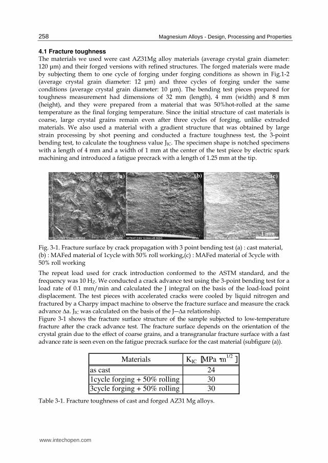
4.1 Fracture toughness The materials we used were cast AZ31Mg alloy materials (average crystal grain diameter: 120 μm) and their forged versions with refined structures. The forged materials were made by subjecting them to one cycle of forging under forging conditions as shown in Fig.1-2 (average crystal grain diameter: 12 μm) and three cycles of forging under the same conditions (average crystal grain diameter: 10 μm). The bending test pieces prepared for toughness measurement had dimensions of 32 mm (length), 4 mm (width) and 8 mm (height), and they were prepared from a material that was 50%hot-rolled at the same temperature as the final forging temperature. Since the initial structure of cast materials is coarse, large crystal grains remain even after three cycles of forging, unlike extruded materials. We also used a material with a gradient structure that was obtained by large strain processing by shot peening and conducted a fracture toughness test, the 3-point bending test, to calculate the toughness value JIC. The specimen shape is notched specimens with a length of 4 mm and a width of 1 mm at the center of the test piece by electric spark machining and introduced a fatigue precrack with a length of 1.25 mm at the tip.
(a) (b) (c)
1 mm
(a) (b) (c)
1 mm
Fig. 3-1. Fracture surface by crack propagation with 3 point bending test (a) : cast material, (b) : MAFed material of 1cycle with 50% roll working,(c) : MAFed material of 3cycle with 50% roll working
The repeat load used for crack introduction conformed to the ASTM standard, and the frequency was 10 HZ. We conducted a crack advance test using the 3-point bending test for a load rate of 0.1 mm/min and calculated the J integral on the basis of the load-load point displacement. The test pieces with accelerated cracks were cooled by liquid nitrogen and fractured by a Charpy impact machine to observe the fracture surface and measure the crack advance ∆a. JIC was calculated on the basis of the J―∆a relationship. Figure 3-1 shows the fracture surface structure of the sample subjected to low-temperature fracture after the crack advance test. The fracture surface depends on the orientation of the crystal grain due to the effect of coarse grains, and a transgranular fracture surface with a fast advance rate is seen even on the fatigue precrack surface for the cast material (subfigure (a)).
Materials KIC [MPa・m1/2]
as cast 24
1cycle forging + 50% rolling 30
3cycle forging + 50% rolling 30
Table 3-1. Fracture toughness of cast and forged AZ31 Mg alloys.
www.intechopen.com
Grain Refinement of Magnesium Alloy by Multiaxial Alternative Forging and Hydrogenation Treatment
259
Compared to this, subfigures (b) and (c) show similar crack advances with a relatively smooth fracture surface, and the differences in the fatigue precrack fracture surface and static crack advance range is evident. KIC values calculated from KIC are shown in Table 3-1. Forged materials show higher toughness values than cast materials. The KIC values were identical for the one-cycle and 3-cycle materials. The toughness values obtained by us were similar to the fracture toughness of commercial materials that is given in a published report (28 MPa m1/2). Therefore, the structural refinement to crystal grains with a diameter of about 10 μm has little effect on the toughness value for the AZ31 in the cast material.
4.2 Refined structure and fatigue characteristics The materials we used in the fatigue test were the AZ31 extruded material and the same material that was forged for one cycle under forging conditions B. The fatigue test was conducted using a tensile-compression round bar test piece with a diameter of 6 mm and a gage length of 15 mm along with a controlled load and 10 Hz frequency. We also used a 50 x 50 mm CT test piece with a plate thickness of 5 mm to observe the crack generation process.
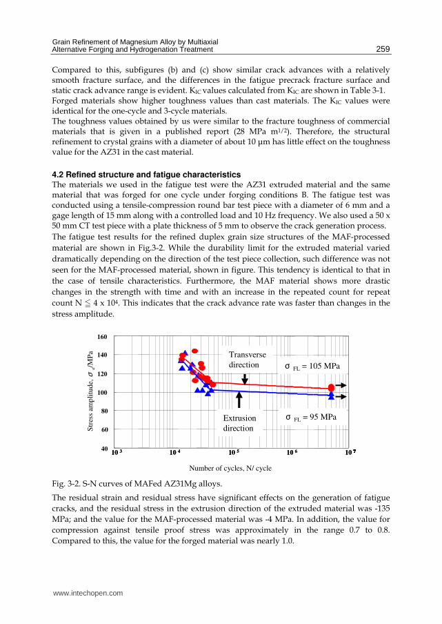
The fatigue test results for the refined duplex grain size structures of the MAF-processed
material are shown in Fig.3-2. While the durability limit for the extruded material varied
dramatically depending on the direction of the test piece collection, such difference was not
seen for the MAF-processed material, shown in figure. This tendency is identical to that in
the case of tensile characteristics. Furthermore, the MAF material shows more drastic
changes in the strength with time and with an increase in the repeated count for repeat
count N N 4 x 10⁴. This indicates that the crack advance rate was faster than changes in the
stress amplitude.
40
60
80
100
120
140
160
140
120
100
80
60
40
160
10 3 10 4 10 5 10 6 10 7
Str
ess
am
pli
tud
eσ
a/M
Pa
Number of cycles N
Extrusion direction
Transverse direction
σ FL = 105 MPa
σ FL = 95MPa
40
60
80
100
120
140
160
140
120
100
80
60
40
160
10 3 10 4 10 5 10 6 10 7
Str
ess
am
pli
tud
eσ
a/M
Pa
Number of cycles
Extrusion direction
Transverse direction
40
60
80
100
120
140
160
40
60
80
100
120
140
160
140
120
100
80
60
40
160
10 3 10 4 10 5 10 6 10 7
Str
ess
am
pli
tud
eσ
a/M
Pa 140
120
100
80
60
40
160
10 3 10 4 10 5 10 6 10 7
Str
ess
am
pli
tud
eσ
a/M
Pa Transverse
direction
Extrusion
direction
σ FL = 105 MPa
σ FL = 95 MPa
Number of cycles, N/ cycle
Str
ess
amp
litu
de,
σa/M
Pa
40
60
80
100
120
140
160
140
120
100
80
60
40
160
10 3 10 4 10 5 10 6 10 7
Str
ess
am
pli
tud
eσ
a/M
Pa
Number of cycles N
Extrusion direction
Transverse direction
40
60
80
100
120
140
160
140
120
100
80
60
40
160
10 3 10 4 10 5 10 6 10 7
Str
ess
am
pli
tud
eσ
a/M
Pa
Number of cycles N
Extrusion direction
Transverse direction
40
60
80
100
120
140
160
40
60
80
100
120
140
160
140
120
100
80
60
40
160
10 3 10 4 10 5 10 6 10 7
Str
ess
am
pli
tud
eσ
a/M
Pa
Number of cycles N
Extrusion direction
Transverse direction
140
120
100
80
60
40
160
10 3 10 4 10 5 10 6 10 7
Str
ess
am
pli
tud
eσ
a/M
Pa
Number of cycles N
Extrusion direction
Transverse direction
Extrusion direction
Transverse direction
σ FL = 105 MPa
σ FL = 95MPa
σ FL = 105 MPaσ FL = 105 MPa
σ FL = 95MPaσ FL = 95MPa
40
60
80
100
120
140
160
140
120
100
80
60
40
160
10 3 10 4 10 5 10 6 10 7
Str
ess
am
pli
tud
eσ
a/M
Pa
Number of cycles
Extrusion direction
Transverse direction
40
60
80
100
120
140
160
40
60
80
100
120
140
160
140
120
100
80
60
40
160
10 3 10 4 10 5 10 6 10 7
Str
ess
am
pli
tud
eσ
a/M
Pa
Number of cycles
Extrusion direction
Transverse direction
140
120
100
80
60
40
160
10 3 10 4 10 5 10 6 10 7
Str
ess
am
pli
tud
eσ
a/M
Pa
Number of cycles
Extrusion direction
Transverse direction
Extrusion direction
Transverse direction
40
60
80
100
120
140
160
40
60
80
100
120
140
160
40
60
80
100
120
140
160
40
60
80
100
120
140
160
140
120
100
80
60
40
160
10 3 10 4 10 5 10 6 10 7
Str
ess
am
pli
tud
eσ
a/M
Pa 140
120
100
80
60
40
160
10 3 10 4 10 5 10 6 10 7
Str
ess
am
pli
tud
eσ
a/M
Pa Transverse
direction
Extrusion
direction
σ FL = 105 MPa
σ FL = 95 MPa
Number of cycles, N/ cycle
Str
ess
amp
litu
de,
σa/M
Pa
Fig. 3-2. S-N curves of MAFed AZ31Mg alloys.
The residual strain and residual stress have significant effects on the generation of fatigue
cracks, and the residual stress in the extrusion direction of the extruded material was -135
MPa; and the value for the MAF-processed material was -4 MPa. In addition, the value for
compression against tensile proof stress was approximately in the range 0.7 to 0.8.
Compared to this, the value for the forged material was nearly 1.0.
www.intechopen.com

Magnesium Alloys - Design, Processing and Properties
260
When we studied the state of the fracture surface in the fatigue test, the state of fracture
varied between the material loaded with stress amplitude near the durability limit under
which fracture occurs for a repeat count of N O 105 and the material fractured under large
stress amplitude under which fracture occurs for a repeat count of N N 104, The fracture
surface was coarse in both materials when the load stress amplitude was large, and the
crack accelerated vertically in the direction of the load, regardless of the
uniformity/nonuniformity of the grain diameter. Compared to this, the results varied
between the extruded material and the MAF-processed material when the stress amplitude
was near the durability limit. The fracture mainly occurred as a transgranular fracture in the
extruded material and the fracture surface was smooth due to the effect of the grain
diameter.
50 µm
N = 4.1 × 10⁴
σ a = 118 MPa
N = 1.7 × 10⁴
σ a = 140 MPa
(a) (b)
50 µm
N = 4.1 × 10⁴
σ a = 118 MPa
N = 1.7 × 10⁴
σ a = 140 MPa
(a) (b)
Fig. 3-3. Fatigue crack initiation behavior (a) : as-received ,(b) :MAF worked material .
However, fracture occurred with branching of cracks in concurrence with boundary fracture in the initial stages of fracture in the MAF-processed material. The effects of fine grains and coarse grains were clearly observed, and a twin crystal fracture was also seen in the case of coarse grains. Although it is expected that these effects would manifest in fatigue life as well, both the tensile strength and the ratio of fatigue strength did not show large changes in our experiment results, showing no significant difference in the crack advance rate between the materials. This coincides with the test results for the rolled material. It is surmised that the durability limit is different for the two materials due to the timing of crack generation. Figure 3-3 shows the status near the crack generation in the specimen and the MAF material. As shown in the figure, the crack propagates through the coarse crystal grain in the specimen. On the other hand, the crack propagates on the fine crystal boundaries in the MAF material. These cracks continue to advance for more than 90% of their total lifetime, and it is surmised that the initial crack generation and propagation timing greatly affect the total lifetime. However, this point needs to be examined in detail through further study.
www.intechopen.com

Grain Refinement of Magnesium Alloy by Multiaxial Alternative Forging and Hydrogenation Treatment
261
Although the fatigue durability limit for the extruded material shows large differences between the extrusion direction and the direction perpendicular to it, this difference almost completely disappears in the MAF-processed material, showing a tendency similar to that for tensile proof stress. Furthermore, there is little difference in the state of fatigue crack propagation between the extruded material and MAF-processed material under high-amplitude loads, and the fracture surface conditions mainly give rise to transgranular fractures. However, the effect of crystal orientation appears locally in the low-amplitude range and grain boundary fracture is significant in the MAF-processed material. There was no significant difference between the materials with regard to the rate of the macroscopic crack propagation process during the total lifetime, and a large difference was observed until rapid crack advance. It is this crack generation and propagation process that the no uniform structure affects during the fatigue lifetime.
40
60
80
100
120
140
160
1.0E+03 1.0E+04 1.0E+05 1.0E+06 1.0E+07 1.0E+08
Number of cycles
Stress amplitude σ/MPa
MAF*B
MAF*E
MAF*F
MAF+SP
1.0 × 10³ 1.0 × 10⁴ 1.0 × 10⁵ 1.0 × 10⁶ 1.0 × 10⁷ 1.0 × 10⁸
40
60
80
100
120
140
160
Number of cycle, N/cycle
Str
ess
amp
litu
de,
σ/M
Pa
40
60
80
100
120
140
160
1.0E+03 1.0E+04 1.0E+05 1.0E+06 1.0E+07 1.0E+08
Number of cycles
Stress amplitude σ/MPa
MAF*B
MAF*E
MAF*F
MAF+SP
40
60
80
100
120
140
160
1.0E+03 1.0E+04 1.0E+05 1.0E+06 1.0E+07 1.0E+08
Number of cycles
Stress amplitude σ/MPa
MAF*B
MAF*E
MAF*F
MAF+SP
1.0 × 10³ 1.0 × 10⁴ 1.0 × 10⁵ 1.0 × 10⁶ 1.0 × 10⁷ 1.0 × 10⁸
40
60
80
100
120
140
160
Number of cycle, N/cycle
Str
ess
amp
litu
de,
σ/M
Pa
Fig. 3-4. S-N curves of MAFed AZ31 alloy by various forging condition working and fracture surfaces.
On the basis of these results, we conducted a fatigue test using a cube with an edge of 100 mm prepared from forged material processed by performing shot peening under forging conditions F. The test conditions were identical to those previously described. The fatigue test results are shown in Fig.3-4. The sample under forging conditions F was not processed thermally after forging. The crystal structure comprised mainly structural changes resulting from dynamic recrystallization, as described in Section 2, and it had a duplex grain size structure because it was processed only for one cycle. However, traces of large deformation, such as twin crystals and sliding, remained in the coarse grains with diameters of 10–20 μm that remained as islands, indicating that the accumulation of strain. Fine crystals with diameters of several micrometers or smaller exist among the coarse grains, but the durability limit is improved to 120 MPa or greater. Furthermore, the gradient structure shown in Fig.3-5 is formed when the surface treatment attempted in the previous section is carried out under forging conditions F. It is surmised that proof stress improvement and the generation of twin crystals were somewhat
www.intechopen.com

Magnesium Alloys - Design, Processing and Properties
262
Fig. 3-5. Sub micron size microstructure at surface of AZ31 Mg alloy by MAF work, hydrogen treatment and shot penning with recrystallization treatment.
suppressed on the compressed side. It is possible to extend the lifetime by controlling the
delay in crack generation timing by structural refinement and by controlling the delay in the
crack advance rate by randomization of structural orientation based on our observation of
crack generation behavior
5. Summary
We used commercially available materials, AZ31 and AZ61 magnesium alloys, and tried to
refine their structure and improve their mechanical properties. Our findings are outlined
below:
1. It was possible to obtain a fine structure with a crystal grain diameter of about 2–3 μm
by properly selecting the process temperature for MAF processing, which is a type of
large strain process. Although the degree of structural fineness and refinement
advances with the number of repeated forging processes, they reach saturation in 4–5
cycles due to the limit in the tolerable work strain that can be introduced.
2. A structure with an average grain diameter of 5–6 μm can be obtained in one cycle of
forging; however, such a structure is a duplex grain size structure. The degree of duplex
grain size can be reduced by performing a recrystallization thermal process.
3. The method involving the use of hydrogenation requires a high-pressure hydrogen
environment and it is of limited use. However, it is possible to refine the surface
structure to the submicron level by using only shot peening for surface reinforcement
and by performing a thermal process. Although the tensile strength improvement at
room temperature resulting from structural refinement remained around 25%, the
extension was improved by 30%.
4. Although the fracture toughness of a material with a crystal grain diameter of 10 μm
improved only slightly relative to that of a commercially available material, it is still a
dramatic improvement relative to the cast material. The durability limit in the fatigue
test improved by 30% compared to the commercially available material when fine grain
material was subjected to crystal refinement, and the anisotropy of strength in the
material direction decreased upon forging. Its main effect is the increase in time until
initial crack generation.
www.intechopen.com

Grain Refinement of Magnesium Alloy by Multiaxial Alternative Forging and Hydrogenation Treatment
263
6. Future reserch
In this present study, it was clear that improvement mechanical properties and formability of magnesium alloys by Multi-axial alternative forging was effective thermo-mechanical and microstructure-controlled process. To make the surface layer with the more fine structure, the sever strain forming was combined with hydrogen adsorption processing and the way to make the structure of the material surface with the inclination organization has been developed. Our research topic in the future for practical applications is as follows. 1. To improve duplex microstructures formed by sever plastic deformation, optimized of
heat treatment, plastic deformation process and microstructure controlled. 2. Evaluation of mechanical properties and formability of functional materials under
several conditions. 3. Fabrication of bulk materials that has uniform microstructure and mechanical
properties. Mechanical properties of the multi-scale under various stress condition for design of practical goods application are investigated to reach the objective, and it aims at the optimization of microstructure, worked process, forming process and mechanical properties.
7. References
Ameyama,K.(1998). Low Temperature Recrystallization and Formation of an Ultra Fine
(γ +σ) Micro- duplex Structure in a SUS316 Stainless Steel, Scripta MaterVol.38:517-
522
Berbon,P.,Komura,S.,Utsunomiya,A.,Z.horita,Z.,Furukawa,M.,N.Nemoto,N.&Langdon,T.(19
99).An Evaluation of Superplasticity in Aluminum-Scandium Alloys Processed by
Equal-Channel Angular Pressing, Mater.TransVol.40:772-778
Ishida,S.,Noda,M.,Funami,K.&Mori.H(2007).Grain Refinement and Mechanical Properties of
Magune- sium Alloy by Hydrogenation Treatment, Materials Science Forum
Vol.558-559:757-762
Machida,N.,Noda,M.,Funami,K.&Kobayashi,M.(2004).Effect of Hydrogenation Treatment
on Grain Refinement of Reaction Sintered Ti-6Al-4V Alloy
Composites,Mater.TransVol.45:2288-2294
Nagata,Y.,Noda,M.,Shimizu,H.,Funami,K.&Mori,H.(2007)Improvement of the Fatigue
Characteristic of AZ31 Magunesium Alloy by Microstructure Control,Materials
Science ForumVol.558-559 :781 -786
Noda,M.,Funami,K.& Suwahara,Y.(2005).Effect of Constraint and Strain Path on Evolution
of Ultra fine Grained Microstructure by Multi-axial Alternative Forging Materials,
Materials Science Forum Vol.475 -479:3471-3474
Noda,M.&Funami,K.(2006).Deformation Behavior of Fine Grained Al-Mg Alloy under
Biaxial Stress, Materials Science Forum Vol.503- 504:475-480
Tsuji,N.,Shiotsuki,K.&Saito,Y.(1999). Superplasticity of Ultra-Fine Grained Al-Mg Alloy
Produced by Accumulative Roll-Bonding, Mater.TransVol.40:765-771
Yoshimura,H.,Kimura,K.,Hayashi,M.,Ishii,M.,Hanamura,T.&Takamura,J.(1994). Ultra-fine
Equiaxed Grain Refinement and Improvement of Mechanical Properties of ┙+┚
www.intechopen.com

Magnesium Alloys - Design, Processing and Properties
264
Type Titanium Alloys by Hydrogenation, Hot Working, Heat Treatment and
Dehydrogenation, Mater.Trans.JIM Vol.35: 266-272
Xing,J.,Soda,H.,Yang,X.,Miura,H.&Sakai,T.(2005).Ultra-Fine Grain Development in an AZ31
Magnesium Alloy during Multi-Directional Forging under Decreasing
Temperature Conditions, Mater.Trans. Vol.46: 1646-1650
www.intechopen.com

Magnesium Alloys - Design, Processing and PropertiesEdited by Frank Czerwinski
ISBN 978-953-307-520-4Hard cover, 526 pagesPublisher InTechPublished online 14, January, 2011Published in print edition January, 2011
InTech EuropeUniversity Campus STeP Ri Slavka Krautzeka 83/A 51000 Rijeka, Croatia Phone: +385 (51) 770 447 Fax: +385 (51) 686 166www.intechopen.com
InTech ChinaUnit 405, Office Block, Hotel Equatorial Shanghai No.65, Yan An Road (West), Shanghai, 200040, China
Phone: +86-21-62489820 Fax: +86-21-62489821
Scientists and engineers for decades searched to utilize magnesium, known of its low density, for light-weighting in many industrial sectors. This book provides a broad review of recent global developments intheory and practice of modern magnesium alloys. It covers fundamental aspects of alloy strengthening,recrystallization, details of microstructure and a unique role of grain refinement. The theory is linked withelements of alloy design and specific properties, including fatigue and creep resistance. Also technologies ofalloy formation and processing, such as sheet rolling, semi-solid forming, welding and joining are considered.An opportunity of creation the metal matrix composite based on magnesium matrix is described along withcarbon nanotubes as an effective reinforcement. A mixture of science and technology makes this book veryuseful for professionals from academia and industry.
How to referenceIn order to correctly reference this scholarly work, feel free to copy and paste the following:
Masafuni Noda and Kunio Funami (2011). Grain Refinement of Magnesium Alloy by Multiaxial AlternativeForging and Hydrogenation Treatment, Magnesium Alloys - Design, Processing and Properties, FrankCzerwinski (Ed.), ISBN: 978-953-307-520-4, InTech, Available from:http://www.intechopen.com/books/magnesium-alloys-design-processing-and-properties/grain-refinement-of-magnesium-alloy-by-multiaxial-alternative-forging-and-hydrogenation-treatment

© 2011 The Author(s). Licensee IntechOpen. This chapter is distributedunder the terms of the Creative Commons Attribution-NonCommercial-ShareAlike-3.0 License, which permits use, distribution and reproduction fornon-commercial purposes, provided the original is properly cited andderivative works building on this content are distributed under the samelicense.