Grafica e Stampa SERIART - Fabriano (AN) - ...
80
USER AND MAINTENANCE MANUAL USER AND MAINTENANCE MANUAL TM RACING USES and ADVICES TM RACING USES and ADVICES TM 4 STROKE 2009
Transcript of Grafica e Stampa SERIART - Fabriano (AN) - ...

Grafica e Stampa SERIART - Fabriano (AN) - www.seriart.com
ENGLISH
USER AND
MAINTENANCE
MANUAL
USER AND
MAINTENANCE
MANUAL
TM RACING
USES and ADVICES
TM RACING
USES and ADVICES
TM 4 STROKE 2009Pu
bli
sh
ed
an
d p
rin
ted
by
- F
ab
ria
no
(A
N)
- w
ww
.se
ria
rt.c
om
SE
RIA
RT
SER
IART
TM-02 (ed. 12/08)

ENGLISHENGLISH 2

ENGLISHENGLISHENGLISH3
ENGINE NUMBERENGINE NUMBERENGINE NUMBERENGINE NUMBERENGINE NUMBER
KEY NUMBERKEY NUMBERKEY NUMBERKEY NUMBERKEY NUMBER
STSTSTSTSTAMP OF AMP OF AMP OF AMP OF AMP OF THE THE THE THE THE AAAAAUTHORISED DEALERUTHORISED DEALERUTHORISED DEALERUTHORISED DEALERUTHORISED DEALER
TM reserves the right to carry out changes without forewarning. The specifications can change from country to country.All indications are valid subject to spelling and printing errors.
FRAME NUMBERFRAME NUMBERFRAME NUMBERFRAME NUMBERFRAME NUMBER
Please make note of your motorcycle’s serial numbers in the boxes below.When you must contact TM for spare parts, updating requests or to signal problems, indicate the model, cylinder capacity, year
of manufacture and most of all the frame number and the engine serial number.
IMPORIMPORIMPORIMPORIMPORTTTTTANTANTANTANTANTYOU ARE ADVISED TO READ THIS MANUAL CAREFULLY BEFORE USING YOUR MOTO TM.IT CONTAINS A LOT OF INFORMATION AND ADVICE THAT WILL MAKE THE USE AND MAINTENANCE OF THEMOTORCYCLE MUCH EASIER AND SAFER.
IT IS IN YOUR SPECIFIC INTEREST TO PAY PARTICULAR ATTENTION TO THE WARNINGS INDICATED IN THEFOLLOWING WAY:
DDDDDANGERANGERANGERANGERANGERFAILURE TO COMPLY WITH THESE WARNINGS RISKS LIVES!
WARNINGWARNINGWARNINGWARNINGWARNINGFAILURE TO COMPLY WITH THESE WARNINGS COULD CAUSE DAMAGE TO PARTS OF THE MOTORCYCLEOR MAKE IT UNSAFE FOR USE.

ENGLISHENGLISH 4
Dear Dear Dear Dear Dear TM customerTM customerTM customerTM customerTM customer,,,,,
We would like to congratulate you for having chosen a TM motorcycle.
Your TM is a competitive and modern motorcycle that will surely give you a lot of satisfaction if you treat itaccording to the provisions contained in this manual. Before starting up your TM motorcycle for the first time,you must read this manual carefully so as to understand the regulations for use and the features of yournew motorcycle.Only in this way will you know how to adjust the motor cycle, and to adapt it in the best way possible toyour personal characteristics and how to protect yourself from injury. This manual also contains importantinformation regarding the maintenance of your new motorcycle.This manual is based on the most recent information concerning the product that was available on going to print.Further variations owing to succesive constructive developments of the motorcycle are however possible.This manual is an integral part of the motorcycle, it must be given to the customer at the time of purchase and mustremain with the motor cycle whenever it is re-sold.
Please note that the operations marked with (A) in the “Frame and Engine Maintenance” chapter must be carriedout by a TM.specialised workshop. If these maintenance operations should be necessary during competitions,they must be carried out by a qualified mechanic.
For your safety, only use TM original spare parts and accessories.TM does not assume any responsibility for the use of other products and for damage deriving from them.
We advise you to respect the running in period, inspection periods and established maintenance periods scrupulously.Only full compliance with these regulations will lengthen the life of your motorcycle. Overhauls and repairs mustonly be carried out by a specialised TM workshop.For any information or requests contact a specialised TM workshop, which is backed by the TM importer.Please remember that a lot of technical data and information regarding TM motorcycles is available at: www.tmracing.it.
Motorcycling is a marvellous sport that you will be able to enjoy with your TM motorcycle.Always remember to respect the environment and other people. Always use the motorcycle with caution, it is ineverybodys interest to safeguard the future of our sport.
Enjoy yourself with your TM motorcycle!
TM RACING S.p.A.Via Fano 6 - 61100 PESARO
ITALY
TM RESERVES THE RIGHT TO CHANGE OR TO EXECUTE MODIFICATIONS AS IT DEEMS NECESSARY .
ENGLISHENGLISHENGLISH5
IMPORIMPORIMPORIMPORIMPORTTTTTANT ANT ANT ANT ANT ADADADADADVICE REGARDINGVICE REGARDINGVICE REGARDINGVICE REGARDINGVICE REGARDINGTHE LEGAL WARRANTY AND THETHE LEGAL WARRANTY AND THETHE LEGAL WARRANTY AND THETHE LEGAL WARRANTY AND THETHE LEGAL WARRANTY AND THE
COMMERCOMMERCOMMERCOMMERCOMMERCIAL CIAL CIAL CIAL CIAL WWWWWARRANTYARRANTYARRANTYARRANTYARRANTYTM sport motorcycles are designed and constructed in a manner to support the stress that may beverified in normal road and competition use.Competition motorcycles are in compliance with the regulations of the categories actually in force atthe most important international motorcycling federations.
The scrupulous compliance with the established inspections, maintenance and tuning of the engineand chassis part of the motorcycle, indicated in the user manual, is indispensable for correct functioningand to prevent premature wear of the parts of the motorcycle itself.Incorrect tuning of the engine or of the chassis can also jeopardise one’s own safety and that ofothers.
The maintenance operations established in the “Maintenance and Lubrication” table must be carriedout by a specialised TM workshop at the envisioned dates, otherwise any warranty rights will beforfeited.When you must contact your TM Dealer for spare parts, updating requests or to signal problems, indicatethe model, cylinder capacity, year of manufacture and most of all the frame number and the engine serialnumber.
Fuels and lubricants must be those established in the user and maintenance manual and must beused as per maintenance programme. Products of other brands can be used as long as they have theequivalent specifications.
In cases of direct and consequent damage caused by tampering or modifications to the motorcycle,no legal warranty claim can be asserted.
The use of the motorcycle in extreme conditions, for example on muddy and very wet ground, maylead to greater than average wear of components, such as transmission components or the brakes. Itis therefore possible that maintenance or replacement of some parts is necessary before the limitnormally envisioned by the maintenance programme.
MX AND SMX MODELS CANNOT BE USED ON PUBLIC ROADS.The 250, 450 and 530 models in the END, SMR and SMM versions can be used on roads only in theunvaried type-approved version (reduced). Without this power limitation (i.e. reduced) thesemodels can only be used off-the-road, but not on public roads.The END models have been designed for off-the-road resistance competitions (Enduro) and are notsuitable for Motocross.

ENGLISHENGLISH 6
INDEXINDEXINDEXINDEXINDEXINDEXINDEXINDEXINDEXINDEX
PagePOSITION OF SERIAL NUMBER ................................................... 7Frame number ................................................................................ 8Engine number ............................................................................... 8OPERATING CONTROLS............................................................... 9Clutch lever AJP pump.................................................................... 10Clutch lever BREMBO pump ........................................................... 10Manual decompressor lever .......................................................... 10Front brake lever NISSIN pump ...................................................... 10Front brake lever BREMBO radial pump ......................................... 11Electronic digital backlit display tachometer ...................................... 11Engine stop switch (MX/SMX) ....................................................... 11Combination switch (END/SMR/SMM) ............................................. 12Start command and emergency stop(END/MXE.S./SMXE.S./SMR/SMM) .................................................. 12Fuel filler cap...................................................................................13Fuel tap .......................................................................................... 13Choke command (cold starter) ....................................................... 13“By-Pass” command (hot starter) All models with electric starter .... 13“By-Pass” command (hot starter) All models with kickstart ........... 14Idle speed adjustment command .................................................... 14Gear shift pedal ............................................................................. 14Kickstart pedal................................................................................ 14Brake pedal ................................................................................... 15Side stand ...................................................................................... 15Side stand fixing for off-road routes...............................................15Ignition switch ............................................................................... 15Fork adjustment in compression .................................................... 16Fork adjustment in rebound .......................................................... 16Shock absorber adjustment in compression ................................. 17Shock absorber adjustment in rebound ......................................... 18Steering lock .................................................................................. 18ADVICE AND GENERAL RECOMMENDATIONS FORCOMMISSIONING THE MOTORCYCLE......................................... 19Indications for first start-up .......................................................... 20Running in instructions ................................................................... 20INSTRUCTIONS FOR USE ..............................................................21Check before every start-up ........................................................ 22Cold engine start ........................................................................... 23Warm engine start .......................................................................... 23If the engine is “flooded” ................................................................ 24Bike starting.....................................................................................24Shifting gear, accelerating, slowing down .................................... 24Braking ........................................................................................... 26Stopping and parking ..................................................................... 26Fuel ................................................................................................ 27MAINTENANCE AND LUBRICATION TABLE................................. 29FRAME AND ENGINE MAINTENANCE ........................................... 35Check steering bearings and play adjustment .............................. 36Telescopic fork vent screws ......................................................... 37Cleaning telescopic fork dust scraper.............................................37Basic calibration of the chassis on the basis of pilot weight ........... 38Shock absorber calibration and spring check ................................ 38Establishing rear shock lowering in running order ........................ 38Establishing rear shock static lowering ........................................ 39Check telescopic fork basic calibration ......................................... 39Variation of telescopic fork preload .............................................. 39Replacement of fork springs .......................................................... 40Variation of rear shock spring preload .......................................... 40Rear suspension mechanical linkage ............................................. 40
PageCheck chain tension ...................................................................... 41Adjustment of chain tension (all models except SMM) ................... 41Adjustment of chain tension (SMM) ............................................... 42Chain maintenance ........................................................................ 42Chain wear..................................................................................... 43Basic indications for TM disc brakes ............................................. 43Front brake NISSIN pump (END/MX) ................................................ 44Front brake BREMBO radial pump (SMR/SMM/SMX) ....................... 45Check front brake pads ................................................................. 45Replacement of front brake pads ................................................... 46Modification of rear brake pedal base position ............................... 47Check rear brake fluid level .......................................................... 47Top-up rear brake fluid .................................................................. 47Check rear brake pads ................................................................. 48Replacement of rear brake pads .................................................... 48Disassembly and assembly of the front wheel ............................. 48Disassembly and assembly of the rear wheel (all except SMM) .... 49Disassembly and assembly of rear wheel (SMM).......................... 50Check spoke tension ..................................................................... 50Tyres, tyre pressure ...................................................................... 51Check adjustment of magnetic sensor for tachometer .................. 51Battery (all models with E.S.) ......................................................... 51Battery charge ............................................................................. 52Recharge fuse (all models with E.S.) ............................................ 53Standard headlightd (END/SMR/SMM) ............................................ 53Halogen light (END/SMR/SMM) ....................................................... 53“Ciclops” optional headlight (END/SMR/SMM) ................................ 54Standard rear light ......................................................................... 55LED rear light ................................................................................ 55Direction indicator lamp (END/SMR/SMM) ....................................... 55Cooling ........................................................................................... 56Check coolant level ...................................................................... 56Emptying, filling and bleeding of the cooling system........................57Replacement of exhaust silencer packing material..........................57Cleaning the air filter ...................................................................... 58Check hand decompressor adjustment ......................................... 58Throttle cable command adjustment .............................................. 58Hydraulic clutch AJP pump ........................................................... 59Hydraulic clutch BREMBO pump .................................................... 59Bleeding hydraulic clutch ............................................................. 60Carburetor - Idle speed adjustment ................................................ 60Basic indications regarding carburetor wear................................. 61Check fuel level (float height) ....................................................... 61Emptying the carburetor float bowl..................................................62Oil circuit ........................................................................................ 62Check engine oil level ................................................................... 63Engine oil ....................................................................................... 63Change engine oil ...........................................................................63TROUBLESHOOTING ................................................................. 66CLEANING ................................................................................. 68PRECAUTIONS FOR WINTER USE .............................................. 68STORAGE ................................................................................. 68Start-up after seasonal pause........................................................... 68TECHNICAL DATA - ENGINE.................................................... 69/70CARBURETOR SETTINGS ............................................................ 71ENGINE TIGHTENING TORQUES .................................................. 72TECHNICAL DATA-CYCLE PART ............................................ 73-74ALPHABETIC INDEX ................................................................... 75WIRING DIAGRAM .......................................................... appendix

ENGLISHENGLISHENGLISH7

ENGLISHENGLISH 8
POSITION OF SERIAL NUMBERPOSITION OF SERIAL NUMBERPOSITION OF SERIAL NUMBERPOSITION OF SERIAL NUMBERPOSITION OF SERIAL NUMBER
FRAME NUMBERFRAME NUMBERFRAME NUMBERFRAME NUMBERFRAME NUMBER
The frame number is embossed on the right side of the steering metaltube. Make note of this number in the appropriate space on page 3. Inthe END, SMR, SMM models, the serial number is also stated on aplate positioned on the left hand side. See photo.
ENGINE NUMBERENGINE NUMBERENGINE NUMBERENGINE NUMBERENGINE NUMBER
The engine number is engraved on the left side of the engineunderneath the chain pinion. Make note of this number in theappropriate space on page 3.
POSITION OF SERIAL NUMBERPOSITION OF SERIAL NUMBERPOSITION OF SERIAL NUMBERPOSITION OF SERIAL NUMBERPOSITION OF SERIAL NUMBER

ENGLISHENGLISHENGLISH9
ENGLISHENGLISH 10
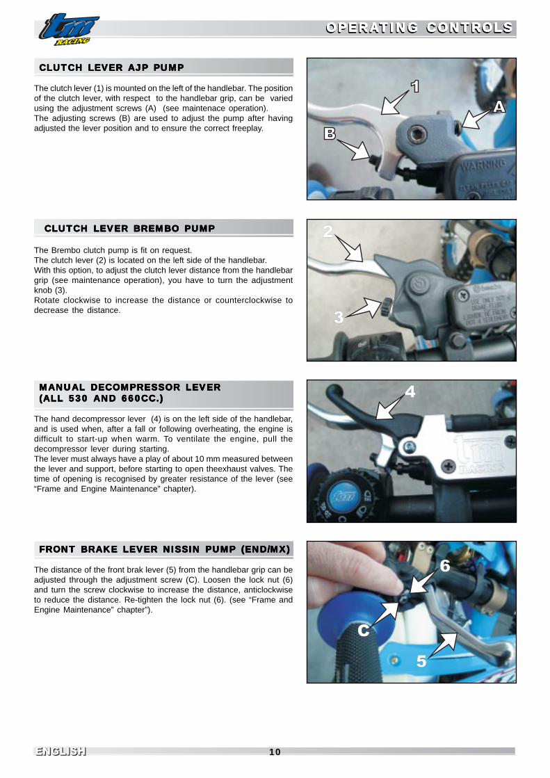
CLUTCH LEVER AJP PUMPCLUTCH LEVER AJP PUMPCLUTCH LEVER AJP PUMPCLUTCH LEVER AJP PUMPCLUTCH LEVER AJP PUMP
The clutch lever (1) is mounted on the left of the handlebar. The positionof the clutch lever, with respect to the handlebar grip, can be variedusing the adjustment screws (A) (see maintenace operation).The adjusting screws (B) are used to adjust the pump after havingadjusted the lever position and to ensure the correct freeplay.
CLUTCH LEVER BREMBO PUMPCLUTCH LEVER BREMBO PUMPCLUTCH LEVER BREMBO PUMPCLUTCH LEVER BREMBO PUMPCLUTCH LEVER BREMBO PUMP
The Brembo clutch pump is fit on request.The clutch lever (2) is located on the left side of the handlebar.With this option, to adjust the clutch lever distance from the handlebargrip (see maintenance operation), you have to turn the adjustmentknob (3).Rotate clockwise to increase the distance or counterclockwise todecrease the distance.
MANUAL DECOMPRESSOR LEVERMANUAL DECOMPRESSOR LEVERMANUAL DECOMPRESSOR LEVERMANUAL DECOMPRESSOR LEVERMANUAL DECOMPRESSOR LEVER(ALL 530 AND 660CC.)(ALL 530 AND 660CC.)(ALL 530 AND 660CC.)(ALL 530 AND 660CC.)(ALL 530 AND 660CC.)
The hand decompressor lever (4) is on the left side of the handlebar,and is used when, after a fall or following overheating, the engine isdifficult to start-up when warm. To ventilate the engine, pull thedecompressor lever during starting.The lever must always have a play of about 10 mm measured betweenthe lever and support, before starting to open theexhaust valves. Thetime of opening is recognised by greater resistance of the lever (see“Frame and Engine Maintenance” chapter).
FRONT BRAKE LEVER NISSIN PUMP (END/MX)FRONT BRAKE LEVER NISSIN PUMP (END/MX)FRONT BRAKE LEVER NISSIN PUMP (END/MX)FRONT BRAKE LEVER NISSIN PUMP (END/MX)FRONT BRAKE LEVER NISSIN PUMP (END/MX)
The distance of the front brak lever (5) from the handlebar grip can beadjusted through the adjustment screw (C). Loosen the lock nut (6)and turn the screw clockwise to increase the distance, anticlockwiseto reduce the distance. Re-tighten the lock nut (6). (see “Frame andEngine Maintenance” chapter”).
OPERAOPERAOPERAOPERAOPERATING CONTRTING CONTRTING CONTRTING CONTRTING CONTROLSOLSOLSOLSOLSOPERAOPERAOPERAOPERAOPERATING CONTRTING CONTRTING CONTRTING CONTRTING CONTROLSOLSOLSOLSOLS
2
3
C
6
5
4

ENGLISHENGLISHENGLISH11
OPERAOPERAOPERAOPERAOPERATING CONTRTING CONTRTING CONTRTING CONTRTING CONTROLSOLSOLSOLSOLSOPERAOPERAOPERAOPERAOPERATING CONTRTING CONTRTING CONTRTING CONTRTING CONTROLSOLSOLSOLSOLS
1
A 1FRONT BRAKE LEVER BREMBO RADIAL PUMPFRONT BRAKE LEVER BREMBO RADIAL PUMPFRONT BRAKE LEVER BREMBO RADIAL PUMPFRONT BRAKE LEVER BREMBO RADIAL PUMPFRONT BRAKE LEVER BREMBO RADIAL PUMP(SMR/SMM/SMX)(SMR/SMM/SMX)(SMR/SMM/SMX)(SMR/SMM/SMX)(SMR/SMM/SMX)
The front brake pump lever (1) is located on the right side of thehandlebar and activates the front wheel brake. The distance of thebrake lever from the handlebar grip can be adjusted through theadjustment knob (A) (see “Frame and Engine Maintenance” chapter)
ELECTRELECTRELECTRELECTRELECTRONIC DIGITONIC DIGITONIC DIGITONIC DIGITONIC DIGITAL BAL BAL BAL BAL BAAAAACKLIT DISPLACKLIT DISPLACKLIT DISPLACKLIT DISPLACKLIT DISPLAYYYYYTTTTTAAAAACHOMETERCHOMETERCHOMETERCHOMETERCHOMETER
See picture (1). It is used on the END/SMR/SMM models. t has a widebacklit display and four pilot lights.In the top there are the left indicator pilot light (2) , the low beam pilotlight (3), the high beam pilot light (4) and the right indicator pilot light(5).Inside the display you find the tachometer (6), the trip odometer (7) andthe total kilometers odometer (8).In the bottom there are two buttons, “SET” (9) and “MODE” (10).
The instrument unit is the Kmh but it can be easily changed in Mph inthe following way: press and hold the “SET” button, while holding itpress once the “MODE” button.Repeat the same operation to switch back to Kmh.
The trip odometer can be reset by holding pressed the “SET” buttononce for at least 4 seconds.The total kilometres odometer resets automatically when reaching thelimit of 99999 Km or Miles.
The instrument switches on automatically when pressing and posi-tioning outwards the red button located near the throttle command andswitches off when pressing and positioning inwards the red buttonitself.
ENGINE STOP SWITCH (MX/SMX)ENGINE STOP SWITCH (MX/SMX)ENGINE STOP SWITCH (MX/SMX)ENGINE STOP SWITCH (MX/SMX)ENGINE STOP SWITCH (MX/SMX)
The engine stop switch is found near to the left handlebar grip.The engine is shutdown using the engine stop switch (1): when it isactivated a shortcircuit is caused in the ignition, which no longer suppliesvoltage to the spark plug.Press the button until the engine switches off and then release.

ENGLISHENGLISH 12
COMBINCOMBINCOMBINCOMBINCOMBINAAAAATION SWITTION SWITTION SWITTION SWITTION SWITCHCHCHCHCH(END/SMR/SMM)(END/SMR/SMM)(END/SMR/SMM)(END/SMR/SMM)(END/SMR/SMM)
This command (1) is located near the handlebar left grip.The use of the switch is very easy.When the symbol (3) on the rotating ring is aligned with the symbol (4)on the switch body, lights are switched off.To switch the lights on, turn the ring (2) counterclockwise until thesymbol (5) is aligned with the symbol (4).Operate in the same way to switch on the low beam (7) and the highbeam (6).Press the button (8) to activate the horn.Press the rocker switch (9) on the left to activate the left hand indicatorand on the right to activate the right hand indicator.
STSTSTSTSTARARARARART COMMAND T COMMAND T COMMAND T COMMAND T COMMAND AND EMERAND EMERAND EMERAND EMERAND EMERGENCY STGENCY STGENCY STGENCY STGENCY STOPOPOPOPOP(END/MXE.S./SMXE.S./SMR/SMM)(END/MXE.S./SMXE.S./SMR/SMM)(END/MXE.S./SMXE.S./SMR/SMM)(END/MXE.S./SMXE.S./SMR/SMM)(END/MXE.S./SMXE.S./SMR/SMM)
In the models with battery and electric ignition, a two-button commandis found at the side of the throttle command, one button is red, the otherblack.The red button (1) has two positions. Positioned inwards, it interruptscontact with the battery, removing the current from all servicesconsumers/ancilleries. The engine will not start even with the pedal.
On these models, position it like this to switch theengine off.
It is advised to leave it like this until the engine is started-up again,otherwise the battery will go flat.
Positioned outwards, it closes the contact with the battery,enables the use of all services, including electric starter.For this reason, never leave it like this with the engineswitched off, otherwise the ignition control unit, whichabsorbs current even when the engine is switched off,can make the battery flat.The black button (2) activates the starter. Press to start-up the engine and release once running.Activate this command for a maximum of 8/10 sec. at atime and wait a few seconds before re-trying.Do not insist for more than 3/4 times: look for the probablefault.Never press this button when the engine is running.
OPERAOPERAOPERAOPERAOPERATING CONTRTING CONTRTING CONTRTING CONTRTING CONTROLSOLSOLSOLSOLSOPERAOPERAOPERAOPERAOPERATING CONTRTING CONTRTING CONTRTING CONTRTING CONTROLSOLSOLSOLSOLS
2
1

ENGLISHENGLISHENGLISH13
FUEL FILLER CAPFUEL FILLER CAPFUEL FILLER CAPFUEL FILLER CAPFUEL FILLER CAP
The fuel fill cap is found on top of the tank.Open: turn the cap in an anti-clockwise directionClose: place the cap on the inlet well and tighten it in a clockwisedirection.
Position the tank’s open vent pipe (1) preventing bends or crushingand making sure that it is inserted correctly.
FUEL FUEL FUEL FUEL FUEL TTTTTAPAPAPAPAP
The tap is located on the left hand side of the tank base.OFF On the OFF position, the fuel tap is closed.ON On the ON position, the fuel tap is open.
When the motorcycle is used, turn the tap to the ON position. Inthis way the fuel flows to the carburetor and the tank empties upto reserve.
RES On the RES position, the reserve is used. After having filled upthe tank, do not forget to move the tap back to the ON position.
Tank capacity (all models)............ 8 Lt. + reserve 1 Lt.
CHOKE COMMAND (COLD STCHOKE COMMAND (COLD STCHOKE COMMAND (COLD STCHOKE COMMAND (COLD STCHOKE COMMAND (COLD STARARARARARTER)TER)TER)TER)TER)
This command is located on the left side of the motorcycle.For MIKUNI carburetorsBy extracting the choke knob (1) as far as possible, a passage isopened in the carburetor, through which the engine can suck additionalfuel. In this way, a “rich” air-fuel mix is obtained. This is necessary forstarting the engine when it is cold.To disconnect the command, push the choke knob inwards to its originalposition.For KEIHIN carburetorsExtract the knob and turn it clockwise to block it. To disconnect it, turnanticlockwise.
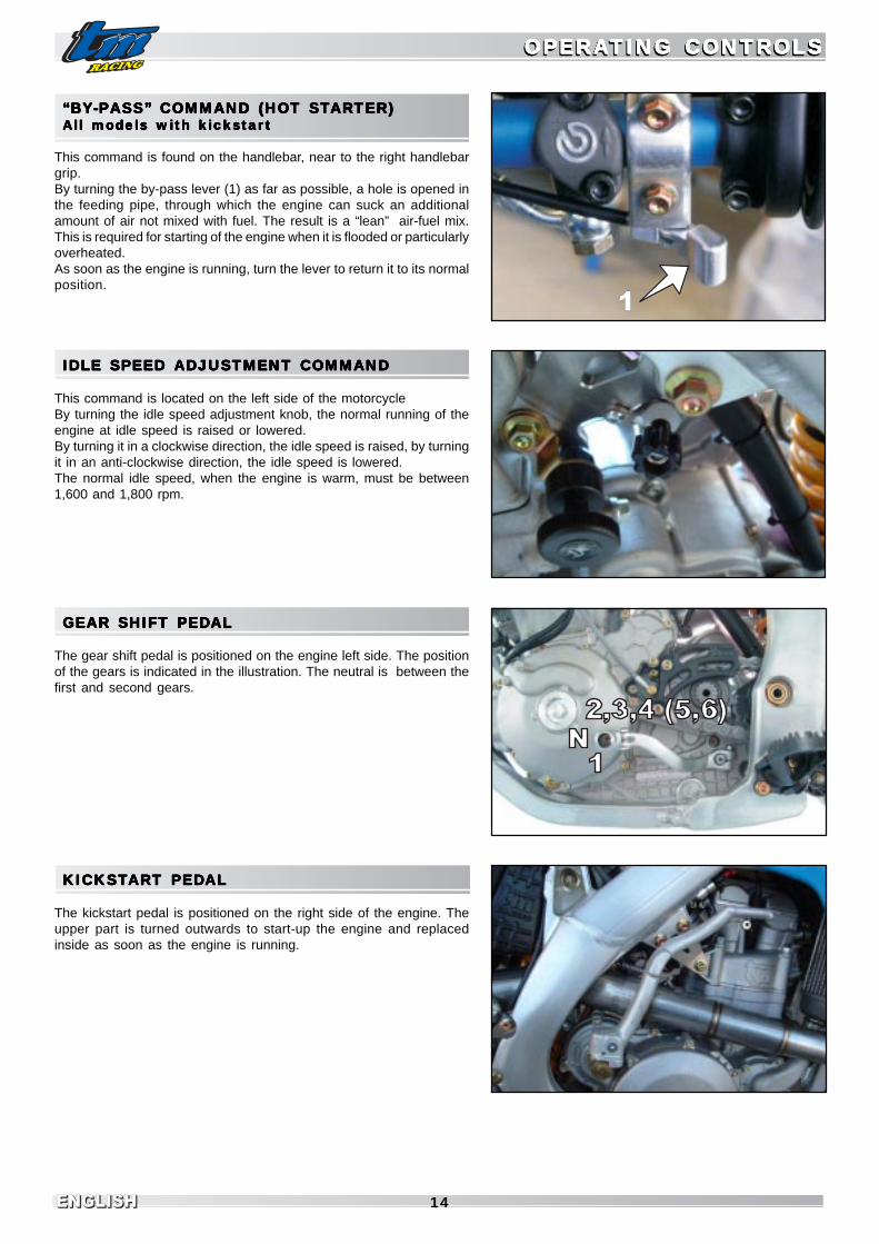
“BY“BY“BY“BY“BY-PASS”-PASS”-PASS”-PASS”-PASS” COMMAND (HO COMMAND (HO COMMAND (HO COMMAND (HO COMMAND (HOT STT STT STT STT STARARARARARTER)TER)TER)TER)TER)All models with electric starAll models with electric starAll models with electric starAll models with electric starAll models with electric starterterterterter
This command is found on the right side of the motor cycle..By pulling the by-pass knob (1) forward as far as possible, a hole isopened in the feeding pipe, through which the engine can suck anadditional amount of air not mixed with fuel. The result is a “lean” air-fuel mix. This is required for starting the engine when it is flooded orparticularly overheated.As soon as the engine is running, push the knob to return it to itsnormal position.
OPERAOPERAOPERAOPERAOPERATING CONTRTING CONTRTING CONTRTING CONTRTING CONTROLSOLSOLSOLSOLSOPERAOPERAOPERAOPERAOPERATING CONTRTING CONTRTING CONTRTING CONTRTING CONTROLSOLSOLSOLSOLS
ENGLISHENGLISH 14
“BY“BY“BY“BY“BY-PASS”-PASS”-PASS”-PASS”-PASS” COMMAND (HO COMMAND (HO COMMAND (HO COMMAND (HO COMMAND (HOT STT STT STT STT STARARARARARTER)TER)TER)TER)TER)All models with kicAll models with kicAll models with kicAll models with kicAll models with kickstarkstarkstarkstarkstarttttt
This command is found on the handlebar, near to the right handlebargrip.By turning the by-pass lever (1) as far as possible, a hole is opened inthe feeding pipe, through which the engine can suck an additionalamount of air not mixed with fuel. The result is a “lean” air-fuel mix.This is required for starting of the engine when it is flooded or particularlyoverheated.As soon as the engine is running, turn the lever to return it to its normalposition.
IDLE SPEED ADJUSTMENT COMMANDIDLE SPEED ADJUSTMENT COMMANDIDLE SPEED ADJUSTMENT COMMANDIDLE SPEED ADJUSTMENT COMMANDIDLE SPEED ADJUSTMENT COMMAND
This command is located on the left side of the motorcycleBy turning the idle speed adjustment knob, the normal running of theengine at idle speed is raised or lowered.By turning it in a clockwise direction, the idle speed is raised, by turningit in an anti-clockwise direction, the idle speed is lowered.The normal idle speed, when the engine is warm, must be between1,600 and 1,800 rpm.
GEAR SHIFT PEDGEAR SHIFT PEDGEAR SHIFT PEDGEAR SHIFT PEDGEAR SHIFT PEDALALALALAL
The gear shift pedal is positioned on the engine left side. The positionof the gears is indicated in the illustration. The neutral is between thefirst and second gears.
KICKSTKICKSTKICKSTKICKSTKICKSTARARARARART PEDT PEDT PEDT PEDT PEDALALALALAL
The kickstart pedal is positioned on the right side of the engine. Theupper part is turned outwards to start-up the engine and replacedinside as soon as the engine is running.
OPERAOPERAOPERAOPERAOPERATING CONTRTING CONTRTING CONTRTING CONTRTING CONTROLSOLSOLSOLSOLSOPERAOPERAOPERAOPERAOPERATING CONTRTING CONTRTING CONTRTING CONTRTING CONTROLSOLSOLSOLSOLS
1

ENGLISHENGLISHENGLISH15
7
BRAKE PEDBRAKE PEDBRAKE PEDBRAKE PEDBRAKE PEDALALALALAL
The brake pedal is positioned in front of the right foot rest. The basicposition can be adjusted on the basis of the position of the saddle(see maintenance operations).
SIDE STSIDE STSIDE STSIDE STSIDE STANDANDANDANDAND
Push the side stand to the floor using the foot and rest the motorcycleon it. Pay attention that the ground is solid and the position stable.
SIDE STSIDE STSIDE STSIDE STSIDE STAND FIXING FOR OFFRAND FIXING FOR OFFRAND FIXING FOR OFFRAND FIXING FOR OFFRAND FIXING FOR OFFROOOOOAD RAD RAD RAD RAD ROUTESOUTESOUTESOUTESOUTES
If you drive the motorcycle off-road, the closed side stand can beadditionally fixed using a rubber band (2).
IGNITION SWITCHIGNITION SWITCHIGNITION SWITCHIGNITION SWITCHIGNITION SWITCH
In the SMR and SMM models an ignition key is added on the left side ofthe dashboard.By turning the key clockwise , the electric circuit is closed and, after thestarter button has been pushed so as to close the contact with thebattery, it is possible to operate the electric starter.To switch the engine off, remember to position the red starter button tointerrupt the battery connection circuit and turn the key anticlockwise.
OPERAOPERAOPERAOPERAOPERATING CONTRTING CONTRTING CONTRTING CONTRTING CONTROLSOLSOLSOLSOLSOPERAOPERAOPERAOPERAOPERATING CONTRTING CONTRTING CONTRTING CONTRTING CONTROLSOLSOLSOLSOLS

ENGLISHENGLISH 16
OPERAOPERAOPERAOPERAOPERATING CONTRTING CONTRTING CONTRTING CONTRTING CONTROLSOLSOLSOLSOLSOPERAOPERAOPERAOPERAOPERATING CONTRTING CONTRTING CONTRTING CONTRTING CONTROLSOLSOLSOLSOLS
54
8
3
1
2
5
4
FORK ADJUSTMENT IN COMPRESSIONFORK ADJUSTMENT IN COMPRESSIONFORK ADJUSTMENT IN COMPRESSIONFORK ADJUSTMENT IN COMPRESSIONFORK ADJUSTMENT IN COMPRESSION
The hydraulic brake system determines the behaviour of the fork in thein compression stroke. The degree of hydraulic dampening incompression can be adjusted on the basis of pilot preferences and/orhardness of the spring installed.
MARZOCCHI USD FORKThe adjustment screw is located in the upper side of the fork cap (4).For this operation, use a screwdriver. By turning the screw clockwise,dampening increases, while turning it anticlockwise, dampeningdecreases. A total of 28 clicks is available.Never turn the side screw (5).PAIOLI USD FORKRemove the rubber hood (1) situated in the lower part of the fork legand turn the adjustment screw (2) using a screwdriver. By turning thescrew clockwise, dampening increases, turning it anticlockwise thedampening decreases. A total of 26 clicks are available.OHLINS USD FORKThe adjustment screw (3) is located in the bottom of the fork leg.Operate using a screwdriver. Turning the screw clockwise thedampening increases, turning it anticlockwise the dampeningdecreases. A total of 20 clicks are available.
WARNINGBEFORE STARTING IT IS ADVISED TO TIGHTEN THE ADJUSTER FROM THESTANDARD POSITION TO THE “TOTALLY CLOSED” POSITION AND COUNT THENOTCHES DETECTED SO THAT THE STANDARD POSITION CAN BE RESTORED.FOR CONVENTION, THE NOTCHES ARE INDICATED FROM THE “TOTALLYCLOSED” POSITION.BOTH RODS MUST HAVE THE SAME ADJUSTMENT.
FORK ADJUSTMENT IN REBOUNDFORK ADJUSTMENT IN REBOUNDFORK ADJUSTMENT IN REBOUNDFORK ADJUSTMENT IN REBOUNDFORK ADJUSTMENT IN REBOUND
The hydraulic dampening in extension determines the behaviour ofthe fork in the rebound stroke.The degree of dampening in rebound can be adjusted on the basis ofpilot preferences and/or hardness of the spring installed.
MARZOCCHI USD FORKThe adjustment screw is located in the lower part of the fork leg (8). For thisoperation, use a screwdriver. By turning the screw clockwise, dampening in-creases, while turning it anticlockwise, dampening decreases. A total of 28clicks are available.PAIOLI USD FORKThe adjustment screw is located in the top side of the fork cap (4).Turning the screw clockwise, dampening increases, turning itanticlockwise dampening decreases. A total of 28 clicks are available.OHLINS USD FORKThe adjustment knob (5) is located in the top side of the fork cap.Operate by hand. Turning the knob clockwise, dampening increases,turning it anticlockwise dampening decreases. A total of 20 clicks areavailable.
WARNINGBEFORE STARTING IT IS ADVISED TO TIGHTEN THE ADJUSTER FROM THESTANDARD POSITION TO THE “TOTALLY CLOSED” POSITION AND COUNT THECLICKS DETECTED SO THAT THE STANDARD POSITION CAN BE RESTORED.FOR CONVENTION, THE NUMBER OF CLICKS IS INDICATED FROM THE “TOTALLYCLOSED” POSITION.BOTH LEGS MUST HAVE THE SAME ADJUSTMENT.
WARNINGFOR FURTHER AND MORE DETAILED INFORMATION REGARDING THE FORK,BOTH STANDARD AND OPTIONAL, REFER TO THE “OWNERS MANUAL”SUPPLIED BY THE MANUFACTURER OF THE FORK SUPPLIED BY TMACCOMPANYING THE MOTORCYCLE.

ENGLISHENGLISHENGLISH17
SHOCK SHOCK SHOCK SHOCK SHOCK ABSORBER ABSORBER ABSORBER ABSORBER ABSORBER ADJUSTADJUSTADJUSTADJUSTADJUST..... IN COMPRESSION IN COMPRESSION IN COMPRESSION IN COMPRESSION IN COMPRESSION
The hydraulic dampening in compression determines the behaviourof the shock absorber in the compression stroke.The degree ofdampening in compression can be adjusted on the basis of pilotpreferences and/or hardness of the spring installed.Both standard and optional shock absorbers mounted on the TM offerthe possibility of double adjustment in compression for low and highspeeds.Low and high speeds mean the movement speed of the damper incompression and not the speed of the motorcycle.
SACHS SHOCK ABSORBER (STANDARD)Low speeds- The adjustment screw (6) is located on the top of thedamper gas tank. Use a screwdriver. By turning the screw clockwise,dampening increases, anticlockwise dampening decreases. A total of24 clicks are available.High speeds - The adjuster is a knob (7) and is concentric to the lowspeed adjustment screw. Operate manually. By turning the knobclockwise, dampening increases, anticlockwise dampeningdecreases. A total of 20 clicks are available.
OHLINS SHOCK ABSORBER (OPTIONAL)Low speeds- The adjustment screw (1) is on the top of the dampergas tank. Use a screwdriver. By turning the screw clockwise,dampening increases, anticlockwise dampening decreases. A total of25 clicks are available.High speeds- The adjuster is a hexagonal ring nut (2) and is concentricto the low speeds adjustment screw. Use a 17mm hexagonal spanner.By turning the nut clockwise, dampening increases, anticlockwisedampening decreases. A total of 4 clicks are available.
WARNINGBEFORE STARTING IT IS ADVISED TO TIGHTEN THE ADJUSTER FROM THESTANDARD POSITION TO THE “TOTALLY CLOSED” POSITION AND COUNT THECLICKS/TURNS DETECTED SO THAT THE STANDARD POSITION CAN BERESTORED.FOR CONVENTION, THE NUMBER OF CLICKS/TURNS ARE INDICATED FROMTHE “TOTALLY CLOSED” POSITION.
OPERAOPERAOPERAOPERAOPERATING CONTRTING CONTRTING CONTRTING CONTRTING CONTROLSOLSOLSOLSOLSOPERAOPERAOPERAOPERAOPERATING CONTRTING CONTRTING CONTRTING CONTRTING CONTROLSOLSOLSOLSOLS

ENGLISHENGLISH 18
SHOCK ABSORBER ADJUSTMENT IN REBOUNDSHOCK ABSORBER ADJUSTMENT IN REBOUNDSHOCK ABSORBER ADJUSTMENT IN REBOUNDSHOCK ABSORBER ADJUSTMENT IN REBOUNDSHOCK ABSORBER ADJUSTMENT IN REBOUND
The hydraulic brake system in rebound determines the behaviour ofthe shock absorber in rebound stroke.The degree of hydraulic brakingin rebound can be adjusted on the basis of pilot preferences and/orhardness of the spring installed.
SACHS SHOCK ABSORBER (STANDARD)The adjustment screw (3) is situated on the fork of the shock absorber(side of mechanical linkage). Use a screwdriver. By turning clockwise,braking increases, anticlockwise it decreases. A total of 40 clicks areavailable.
OHLINS SHOCK ABSORBER (OPTIONAL)The adjustment knob (4) is situated low at the end of the damper rod.Act manually. By turning clockwise (looking from the bottom upwards)braking increases, anticlockwise, it decreases. A total of 40 clicks areavailable.
WARNINGBEFORE STARTING IT IS ADVISED TO TIGHTEN THE ADJUSTER FROM THESTANDARD POSITION TO THE “TOTALLY CLOSED” POSITION AND COUNT THECLICKS DETECTED SO THAT THE STANDARD POSITION CAN BE RESTORED.FOR CONVENTION, THE NUMBER OF CLICKS IS INDICATED FROM THE “TOTALLYCLOSED” POSITION.
THE DAMPER GAS TANK IS FILLED WITH PRESSURISED NITROGEN . NEVERTRY TO DISASSEMBLE THE DAMPER OR CARRY OUT MAINTENANCEOPERATIONS WITHOUT THE HELP OF TECHNICIANS, OTHERWISE PARTSCOULD BE DAMAGED AND PERSONS INJURED
STEERING LOCKSTEERING LOCKSTEERING LOCKSTEERING LOCKSTEERING LOCK
This lock is situated on the left side of the frame steering tube.This lock stops rotation of the handlebar, preventing the motorcyclebeing driven.To lock the steering, turn the handlebar completely to the right, insertthe key, turn it to the left, press, turn to the right and extract.
WARNINGNEVER LEAVE THE KEY IN THE LOCK. BY TURNING THE HANDLEBAR TO THELEFT, THE KEY COULD BE DAMAGED.
OPERAOPERAOPERAOPERAOPERATING CONTRTING CONTRTING CONTRTING CONTRTING CONTROLSOLSOLSOLSOLSOPERAOPERAOPERAOPERAOPERATING CONTRTING CONTRTING CONTRTING CONTRTING CONTROLSOLSOLSOLSOLS
PERICOLO

ENGLISHENGLISHENGLISH19

ENGLISHENGLISH 20
INDICATIONS FOR FIRST STINDICATIONS FOR FIRST STINDICATIONS FOR FIRST STINDICATIONS FOR FIRST STINDICATIONS FOR FIRST STARARARARARTTTTT-UP-UP-UP-UP-UP
- Ensure that the “PRE-DELIVERY OPERATIONS” of yourmotorcycle have been carried out by your TM dealer.
- Carefully read all user instructions before making the firstjourney.
- Become familiar with all operating controls.- Adjust the clutch lever, the front brake lever and the brake
pedal so that they are in the most comfortable position.- Get used to driving in an empty carpark or on land where it is
easy to handle the motorcycle before making a long journey.Also try to move at a slow pace on foot to get used to themotorcycle.
- Do not take routes that are too difficult for your driving abilityand experience.
- On the road, hold the handlebar with both hands and leaveyour feet on the footrests.
- Be careful not to push the brake pedal if you do not wish tobrake. If the brake pedal is not released, the brake pads rubcontinuously and the brake overheats
- Do not modify the motorcycle and always use ORIGINAL TMSPARE PARTS. Spare parts made by other manufacturerscan jeopardise the safety of the motorcycle.
- Motorcycles are sensitive to the movement of weight. Whencarrying luggage, fix it as near as possible to the centre of themotorcycle and distribute the weight equally between the frontand rear wheel.
- Follow running in instructions.
RUNNING IN INSTRUCTIONSRUNNING IN INSTRUCTIONSRUNNING IN INSTRUCTIONSRUNNING IN INSTRUCTIONSRUNNING IN INSTRUCTIONS
The surfaces of components of a new motorcycle, even if theyundergo precision workings, are however less smooth than thesame components in a motorcycle that have been driven for atime: this explains the necessity for running in the new engine.To obtain an optimal bedding of the moving parts of a new engine,it must be taken to produce maximum performance gradually.For this reason, during the first 3 hours of use (1 hour forcompetition use) the engine must only be used up to max. 50%of its power. Moreover, the number of revs. must not exceed7000/min.In the following 5 hours of use (1 hour for competition use) theengine can be used up to max. 75% of its power. Drive themotorcycle in different conditions (road, easy off-road tracts).Do not make long journeys without ever closing the throttle.By following these regulations, you will obtain maximum perfor-mance and longer duration of the motorcycle through time.
WARNINGTHE 250/450/530 END/MX/SMX MODELS HAVE BEEN DEVELOPED WITHNO COMPROMISE FOR OFF-ROAD COMPETITIONS. EVEN IF THE ENDUROMODELS ARE TYPE-APPROVED, PAY ATTENTION WHEN USING ON THEROAD . MOST OF ALL AVOID SUSTAINED ACCELERATION CONSTANTTHROTTLE ON LONG ROADS, ROLL THE THROTTLE ON AND BACKSLIGHTLY.
- ALWAYS WEAR SUITABLE CLOTHING WHEN USING THEMOTORCYCLE. ASTUTE MOTORCYCLISTS THAT DRIVE A TMALWAYS WEAR THE TYPE-APPROVED HELMET, BOOTS, GLOVESAND A JACKET, WHETHER IT IS A LONG OR SHORT JOURNEY. THEPROTECTIVE CLOTHING SHOULD BE BRIGHT SO THAT THEMOTORCYCLIST CAN BE EASILY SEEN BY OTHER ROAD USERS.
- ALWAYS SWITCH THE HEADLIGHT ON DURING THE JOURNEY, SOTHAT OTHER ROAD-USERS CAN SEE YOU IN TIME.
- DO NOT DRINK AND DRIVE.- ONLY USE ORIGINAL TM ACCESSORIES. FRONT COVERINGS, FOR
EXAMPLE, CAN NEGATIVELY AFFETCT THE BEHAVIOUR OF THEMOTORCYCLE ON THE ROAD AT HIGH SPEEDS, OR HAVE NEGA-TIVE INFLUENCE OF THE BEHAVIOUR OF THE MOTORCYCLE DUETO DIFFERENT WEIGHT DISTRIBUTION.
- THE FRONT AND REAR TYRES MUST HAVE THE SAME TYPE OFPROFILE.
- AFTER THE FIRST 30 MINS, OF DRIVING, THE WHEEL SPOKETENSION MUST BE CHECKED. SPOKE TENSION DECREASESQUICKLY ON NEW WHEELS. IF YOU DRIVE WITH LOOSE SPOKES,THE SPOKES MAY BREAK, CAUSING UNSTABLE DRIVINGCONDITIONS (SEE CHECK SPOKE TENSION).
- THE RACING MODELS HAVE BEEN DESIGNED AND PREPARED ONLYFOR ONE PERSON. IT IS PROHIBITED TO TAKE ON PASSENGERS.
- FOLLOW THE HIGHWAY CODE, DRIVE CAREFULLY SO AS TORECOGNISE DANGERS AS SOON AS POSSIBLE.
- ADAPT SPEED TO THE CONDITIONS OF THE ROAD AND YOURDRIVING CAPABILITY.
- DRIVE CAREFULLY ON UNKNOWN ROADS OR LAND.- WHEN OFF-ROAD YOU SHOULD ALWAYS BE ACCOMPANIED BY A
FRIEND WITH A SECOND MOTORCYCLE, SO THAT YOU CAN HELPEACH OTHER IF DIFFICULTIES OCCUR.
- IN DUE TIME, REPLACE THE VISOR OR LENSES OF THE GOGGLES.YOU WILL BE BLINDED AGAINST SUNLIGHT IF THE VISOR ORGOGGLES ARE SCRATCHED.
- DO NOT LEAVE THE MOTORCYCLE UNSUPERVISED IF THE ENGINEIS RUNNING.
- MX AND SMX MODELS ARE NOT TYPE-APPROVED FOR USE ONPUBLIC ROADS OR MOTORWAYS.
- WHEN USING YOUR MOTORCYCLE, ALWAYS KEEP IN MIND THATEXCESSIVE NOISE DISTURBS OTHERS.
DANGER
DANGER
ADADADADADVICE VICE VICE VICE VICE AND GENERAL RECCOMANDAND GENERAL RECCOMANDAND GENERAL RECCOMANDAND GENERAL RECCOMANDAND GENERAL RECCOMANDAAAAATIONS FORTIONS FORTIONS FORTIONS FORTIONS FORCOMMISSIONING COMMISSIONING COMMISSIONING COMMISSIONING COMMISSIONING THE MOTHE MOTHE MOTHE MOTHE MOTTTTTORORORORORCYCYCYCYCYCLECLECLECLECLE
ADADADADADVICE VICE VICE VICE VICE AND GENERAL RECCOMANDAND GENERAL RECCOMANDAND GENERAL RECCOMANDAND GENERAL RECCOMANDAND GENERAL RECCOMANDAAAAATIONS FORTIONS FORTIONS FORTIONS FORTIONS FORCOMMISSIONING COMMISSIONING COMMISSIONING COMMISSIONING COMMISSIONING THE MOTHE MOTHE MOTHE MOTHE MOTTTTTORORORORORCYCYCYCYCYCLECLECLECLECLE

ENGLISHENGLISHENGLISH21

ENGLISHENGLISH 22
CHECK BEFORE EVERCHECK BEFORE EVERCHECK BEFORE EVERCHECK BEFORE EVERCHECK BEFORE EVERY STY STY STY STY STARARARARARTTTTT-UP-UP-UP-UP-UP
To use the motorcycle safely, it must be in a good shape. It is a goodidea to carry out a general check-up of the motorcycle before everystart-up.This check must include the following operations:1 LEVEL OF ENGINE OIL
To ensure adequate lubrication, the level of the oil in the enginemust be kept within the envisioned limits. Using the engine with theoil level below minimum leads to premature wear and successively,to damage and risks to the driver.
2 FUELIf the motorcycle does not have a transparent tank, open the tank capand visually check the quantity of fuel contained in the tank. Re-close the tank, making sure that the open vent pipe is not bent andso impeding the flow of air.
3 CHAINThe drive chain must always be tensioned corretly and well lubricated.
A loose chain knocks and may escape from the sprockets.A too tight chain wears early and may cause wear and breakage ofsome important transmission components.
4 TYRESCheck for any damage. Tyres with cuts or swellings must be replacedimmediately.
Check the depth of the tread which must correspond to the law.Finally, check the air pressure and take it to the values envisioned inthe table, if necessary.Worn tread and unsuitable air pressure worsen driving of themotorcycle and may cause loss of control and serious accidents.
5 BRAKESVerify correct working.Check the level of brake fluid. The reservoir on the pumps aredimensioned in a way that in case of normally worn brake pads thefluid does not need to be topped-up. If the level of brake fluid fallsbelow the minimum level, this indicates a leak in the brake systemor complete consumption of the brake pads. Have the brake systemchecked by a specialised TM workshop, given that in this case thebrakes could fail.
The state of the brake’s flexible pipes and the thickness of the padsmust also be checked.Check the free play and the smoothness of the front brake lever andthe rear brake pedal.
6 FLEXIBLE CABLE COMMANDSCheck the adjustment and correct working of all flexible cablecommands .
7 COOLANTCheck the level of coolant with cold engine. Top-up with the liquidstated in the table, if necessary.
8 ELECTRICAL PLANTWith the engine running, check for the front headlight, the front andrear position lights, the rear stopping light, the direction indicatorlights, the control lights and the horn.
9 LUGGAGECheck that any luggage is well fixed.
INSTRUCTIONS FOR USEINSTRUCTIONS FOR USEINSTRUCTIONS FOR USEINSTRUCTIONS FOR USEINSTRUCTIONS FOR USEINSTRUCTIONS FOR USEINSTRUCTIONS FOR USEINSTRUCTIONS FOR USEINSTRUCTIONS FOR USEINSTRUCTIONS FOR USE

ENGLISHENGLISHENGLISH23
COLD ENGINE STCOLD ENGINE STCOLD ENGINE STCOLD ENGINE STCOLD ENGINE STARARARARARTTTTT
1 Open the fuel tap (1).2 Remove the motorcycle from the stand.3 Put the gears in neutral.4 Activate the choke command (2), which is located on the left side of
the motorcycle.5 WITHOUT opening the throttle, press hardly the kickstarter DOWN
TO THE BOTTOM once or twice, or operate the electric starter.6 Start to warm the engine by accelerating slightly for about 30 secs.
Disconnect the choke (2), which is situated on the left side of themotorcycle.
- ALWAYS WEAR STRONG MOTORCYCLE BOOTS WHEN STARTING UPTHE MOTORCYCLE TO PREVENT INJURY. YOU COULD SLIP OFF OF THEPEDAL OR THE ENGINE COULD KICKBACK AND MAKE YOU KNOCK YOURFOOT VIOLENTLY.
- ALWAYS PRESS THE KICKSTARTER DOWN HARD WITHOUTACCELERATING. KICKSTARTING WITH LITTLE FORCE OR WITH OPENEDTHROTTLE, INCREASES THE RISK OF ENGINE KICK BACK.
- DO NOT START THE ENGINE IN A CLOSED SPACE AND NEVER LEAVE ITRUNNING IN CLOSED SPACES. THE EXHAUST FUMES ARE POISONOUSAND MAY LEAD TO RISK OF UNCONSCIOUSNESS AND DEATH. WHEN THEENGINE IS RUNNING, ALWAYS ENSURE THERE IS SUFFICIENT VENTILATION.
- ALWAYS CHECK THAT THE GEAR IS IN NEUTRAL BEFORE OPERATINGTHE STARTER BUTTON. IF A GEAR IS INSERTED WHEN STARTING THEENGINE, THE MOTORCYCLE WILL JUMP FORWARDS.
WARNING- OPERATE THE STARTER FOR MAX. 5 SECONDS AT A TIME. WAIT ANOTHER
5 SECONDS BEFORE TRYING AGAIN.- DO NOT ALLOW THE ENGINE REVS. TO INCREASE TOO MUCH WHILE THE
ENGINE IS COLD. THIS COULD DAMAGE THE ENGINE BECAUSE THE PISTONHEATS UP AND CONSEQUENTLY, IT EXPANDS QUICKER THAN THE CYLINDER,WHICH IS WATER-COOLED. ALWAYS WARM THE ENGINE AT A STANDSTILLOR MOVE AT LOW REVS.
WWWWWARM ENGINE STARM ENGINE STARM ENGINE STARM ENGINE STARM ENGINE STARARARARARTTTTT
1 Open the fuel tap (1).2 Remove the motorcycle from the stand3 Insert the neutral gear.4 WITHOUT opening the throttle, press hardly the kickstarter DOWN
TO THE BOTTOM once or twice, or operate the electric starter.
WARNING- OPERATE THE STARTER MOTOR FOR MAX. 5 SECONDS AT A TIME. WAIT
ANOTHER 5 SECONDS BEFORE TRYING AGAIN.
DANGER
INSTRUCTIONS FOR USEINSTRUCTIONS FOR USEINSTRUCTIONS FOR USEINSTRUCTIONS FOR USEINSTRUCTIONS FOR USEINSTRUCTIONS FOR USEINSTRUCTIONS FOR USEINSTRUCTIONS FOR USEINSTRUCTIONS FOR USEINSTRUCTIONS FOR USE

ENGLISHENGLISH 24
IF THE ENGINE IS “FLOODED”IF THE ENGINE IS “FLOODED”IF THE ENGINE IS “FLOODED”IF THE ENGINE IS “FLOODED”IF THE ENGINE IS “FLOODED”
In the event of a fall, a certain amount of fuel can flow out of the caburetorand enter the head, “flooding” the engine.To start the engine, pull the “hot start” knob or turn the “hot start” lever(1).WITHOUT opening the throttle push hardly the kickstart pedal DOWNTO THE BOTTOM once or twice or operate the electric starter.On models with a manual decompressor, to eliminate the excess fuelfrom the engine, pull the manual decompressor lever and operate thekickstart pedal 5 -10 times or the electric starter button respectivelytwice for 5 seconds. Start the engine as previously described. Ifnecessary, remove the spark plug and dry it.
WARNING: The carburetor has an accelerator pump. Every time thatyou open the throttle,with the engine running or switched off, a quantityof fuel is sprayed into the inlet tract. If this operation is carried out withthe engine switched off, it causes flooding of the engine, with theconsequent starting difficulties and a dangerous distribution of fuel.NEVER TURN THE THROTTLE WHEN THE ENGINE IS NOT RUNNINGIF NOT STRICTLY NECESSARY. IN ANY CASE DO IT ONLY ONCE ANDNEVER REPEATEDLY!
BIKE STBIKE STBIKE STBIKE STBIKE STARARARARARTINGTINGTINGTINGTING
Pull the clutch lever, insert the first gear, release the clutch lever slowly,accelerating at the same time.
BEFORE STARTING, ALWAYS CHECK THAT THE SIDE STAND HAS BEENLIFTED. IF THE STAND SLIDES ALONG THE GROUND YOU COULD LOOSETHE CONTROL OF THE MOTORCYCLE.
SHIFTING GEAR,SHIFTING GEAR,SHIFTING GEAR,SHIFTING GEAR,SHIFTING GEAR, AAAAACCELERACCELERACCELERACCELERACCELERATINGTINGTINGTINGTING,,,,,SLOWING DOWNSLOWING DOWNSLOWING DOWNSLOWING DOWNSLOWING DOWN
1st gear, which should be selected, is the pulling away and ascentgear. If the circumstances permit (speed limits, traffic, slopes), toincrease speed, insert higher gears. To do this, close the throttle, pullthe clutch lever at the same time, insert the successive gear, releasethe clutch and accelerate up to 1/2 turn of the throttle. Then insert thefollowing gear and repeat this operation until the desired speed isreached and however, permitted by the limits in force.Gradual opening of the accelerator favours careful driving and limitsconsumption. Learn the correct opening of the throttle on the basis ofthe pace at which you want the motorcycle to move. To reduce speed, the throttle must be closed. Brake and shift downthe gears, pulling the clutch lever and inserting a lower gear. Releasethe clutch slowly and accelerate or change gear again . Always increaseor change down the gears one at a time!
DANGER
INSTRUCTIONS FOR USEINSTRUCTIONS FOR USEINSTRUCTIONS FOR USEINSTRUCTIONS FOR USEINSTRUCTIONS FOR USEINSTRUCTIONS FOR USEINSTRUCTIONS FOR USEINSTRUCTIONS FOR USEINSTRUCTIONS FOR USEINSTRUCTIONS FOR USE
1

ENGLISHENGLISHENGLISH25
INDICATION:All TM models do not have a radiator cooling fan and the radiatordimensions have been studied to optimise compactness and weight.The cooling system is sufficient for touristic or sports use.If you want to use an additional cooling fan contact a TM authoriseddealer.
- TM MODELS CAN BE RE-STARTED AT ANY TIME BY KICK OR WITHTHE ELECTRIC STARTER. SWITCH THE ENGINE OFF WHEN YOUINTEND TO KEEP THE MOTORCYCLE AT A STANDSTILL FOR MORETHAN 2 MINUTES.
- AFTER EVERY FALL, THE MOTORCYCLE MUST BE CONTROLLED IN THESAME WAY AS BEFORE EVERY START-UP .
- A DEFORMED HANDLEBAR MUST ALWAYS BE REPLACED. NEVERSTRAIGHTEN THE HANDLEBAR AS IT COULD LOOSE ITS STRENGTH.
WARNING
- USE OF THE ENGINE AT A HIGH NUMBER OF REVS WHEN IT IS COLD,NEGATIVELY AFFECTS THE DURATION OF THE ENGINE. BEFORE USING THEMOTORCYCLE AT FULL WORKING CONDITIONS, IT IS BETTER TO WARM ITADEQUATELY BY DRIVING AT AN AVERAGE SPEED. THE ENGINE HASREACHED ITS WORKING TEMPERATURE AS SOON AS THE RADIATORSBECOME HOT.
- NEVER SHIFT DOWN A GEAR WITHOUT HAVING FIRST SLOWED DOWN. THEENGINE WOULD BE TAKEN TO AN EXCESSIVE NUMBER OF REVS AND THEVALVES AND OTHER ENGINE COMPONENTS WOULD BE DAMAGED. THEREAR WHEEL COULD ALSO LOCK, LEADING TO LOSS OF CONTROL OF THEVEHICLE.
- IF THERE ARE ABNORMAL VIBRATIONS DURING FUNCTIONING, CHECK THATTHE SCREW FASTENERS ARE TIGHTENED WELL.
- IF STRANGE NOISES ARE HEARD DURING DRIVING, STOP IMMEDIATELY,SWITCH THE ENGINE OFF AND CONTACT A TM AUTHORISED DEALER.
DANGER
INSTRUCTIONS FOR USEINSTRUCTIONS FOR USEINSTRUCTIONS FOR USEINSTRUCTIONS FOR USEINSTRUCTIONS FOR USEINSTRUCTIONS FOR USEINSTRUCTIONS FOR USEINSTRUCTIONS FOR USEINSTRUCTIONS FOR USEINSTRUCTIONS FOR USE

ENGLISHENGLISH 26
BRAKINGBRAKINGBRAKINGBRAKINGBRAKING
Close the throttle and brake at the same time progressively with thefront and rear brakes. Insert a lower gear depending on speed. Ondusty, wet or slippery surfaces, operate the brakes and change downthe gears gently without locking the wheels. Locking the wheels leadsto swerving or a fall.When following long descending roads, make use of the engine’sbraking effect. To do this, insert the 1st or 2nd gear, without howeverincreasing the revs. excessively. In this way you will have to brakemuch less and the brakes will not overheat.
- IN CASE OF RAIN, AFTER WASHING THE MOTORCYCLE, AFTERIMMERSION IN WATER OR TRAVELLING OVER WET GROUND, THEBRAKING ACTION COULD BE DELAYED BECAUSE OF WET OR DIRTYBRAKE DISCS.THE BRAKES MUST THEREFORE BE OPERATEDREPEATEDLY UNTIL THE DISCS ARE DRY AND CLEAN.
- THE BRAKING ACTION CAN ALSO BE DELAYED WHEN TRAVELLING ONDIRTY ROADS OR ROADS COVERED WITH SALT. THE BRAKES MUST BEOPERATED UNTIL THE DISCS ARE CLEAN.
- WHEN THE BRAKE DISCS ARE DIRTY THERE IS GREATER WEAR OF THEPADS AND THE BRAKE DISCS THEMSELVES.
- AFTER USING THE BRAKES, THE DISC, THE PADS, THE CALIPERS ANDTHE BRAKE FLUID HEAT UP. THE HOTTER THESE PARTS, THE LESS THEBRAKING EFFECT. IN CASE OF OVERHEATING THE ENTIRE BRAKINGSYSTEM MAY NOT WORK.
- IF THE FORCE AT THE FRONT BRAKE LEVER OR BRAKE PEDAL IS MINIMAL,THERE COULD BE A FAULT IN THE BRAKING SYSTEM. IN THIS CASE IT ISA GOOD IDEA TO HAVE THE MOTORCYCLE CHECKED BY AN AUTHORISEDTM DEALER.
STSTSTSTSTOPPING OPPING OPPING OPPING OPPING AND PAND PAND PAND PAND PARKINGARKINGARKINGARKINGARKING
Stop the motorcycle and shift into neutral. To switch the motorcycle off,press, at normal minimum revs, the engine stop switch until the enginehas stopped, or the red emergency shutdown button. In this case, it isadvised to leave the red button in this way until the engine is startedagain.Close the fuel tap, park on solid ground and lock the motorcycleusing the steering lock..
MOTORCYCLES PRODUCE A LOT OF HEAT DURING WORKING. THE ENGINE,RADIATORS, EXHAUST SYSTEM, BRAKE DISCS AS WELL AS SHOCKABSORBERS CAN ALL BECOME VERY HOT. NEVER TOUCH THESE PARTSWHEN DRIVING AND AFTER HAVING SWITCHED THE ENGINE OFF, PARK THEMOTORCYCLE IN A WAY THAT PEDESTRIANS CANNOT TOUCH THEM ANDBE BURNED.
WARNING- NEVER SWITCH THE ENGINE OFF USING THE DECOMPRESSOR LEVER, BUT
USE THE ENGINE STOP SWITCH OR THE EMERGENCY SHUTDOWN BUTTON.- THE FUEL TAP MUST ALWAYS BE CLOSED WHEN THE MOTORCYCLE IS
PARKED. IF IT IS NOT CLOSED, THE FUEL COULD RUN OUT INTO THECARBURETOR AND PENETRATE THE ENGINE, FLOODING IT.
- NEVER PARK WITH THE ENGINE RUNNING OR PARK THE MOTORCYLE INPLACES WHERE THERE IS THE RISK OF FIRE DUE TO DRY GRASS OR OTHEREASILY INFLAMMABLE MATERIALS.
DANGER
DANGER
INSTRUCTIONS FOR USEINSTRUCTIONS FOR USEINSTRUCTIONS FOR USEINSTRUCTIONS FOR USEINSTRUCTIONS FOR USEINSTRUCTIONS FOR USEINSTRUCTIONS FOR USEINSTRUCTIONS FOR USEINSTRUCTIONS FOR USEINSTRUCTIONS FOR USE

ENGLISHENGLISHENGLISH27
INDICATIONS REGARDING THE SIDE STAND:Push the stand forward until it stops and lean the motorcycle on it.Ensure that the ground is solid and the parking position is stable. Forgreater safety insert the 1st gear.
WARNINGTHE SIDE STAND IS DESIGNED ONLY FOR THE WEIGHT OF THE MOTORCYCLE.NEVER SIT ON THE MOTORCYCLE WHEN IT IS RESTING ON THE SIDE STAND,OTHERWISE THE STAND MAY BE DAMAGED AND THE MOTORCYCLE CANFALL.
FUELFUELFUELFUELFUEL
TM engines require super unleaded fuel with at least 95 RON.
WARNINGFILL THE TANK WITH UNLEADED FUEL WITH A MINIMUM OCTANE NUMBER OF95. NEVER USE FUEL WITH AN OCTANE NUMBER LOWER THAN 95, BECAUSETHIS WOULD DAMAGE THE ENGINE.
FUEL IS HIGHLY INFLAMMABLE AND TOXIC. HANDLE FUEL WITH GREATCARE. DO NOT FILL-UP WITH FUEL NEAR TO FLAMES OR CIGARETTES.ALWAYS SWITCH THE ENGINE OFF WHEN FILLING UP WITH FUEL. NEVERPOUR FUEL ONTO THE ENGINE OR ONTO THE EXHAUST PIPE. IF ANY FUELIS ACCIDENTLY POURED ONTO THESE PARTS, DRY IT IMMEDIATELY USINGA CLOTH. IF FUEL IS SWALLOWED OR SPRAYED INTO THE EYES, SEEKMEDICAL HELP IMMEDIATELY.
Fuel expands when heated. Therefore, never fill the tank completelywith high environmental temperatures.
DANGER
INSTRUCTIONS FOR USEINSTRUCTIONS FOR USEINSTRUCTIONS FOR USEINSTRUCTIONS FOR USEINSTRUCTIONS FOR USEINSTRUCTIONS FOR USEINSTRUCTIONS FOR USEINSTRUCTIONS FOR USEINSTRUCTIONS FOR USEINSTRUCTIONS FOR USE

ENGLISHENGLISH 28

ENGLISHENGLISHENGLISH29

ENGLISHENGLISH 30
OTHER IMPORTANT MAINTENANCE OPERATIONS RECCOMMENDED EVERY YEAROTHER IMPORTANT MAINTENANCE OPERATIONS RECCOMMENDED EVERY YEAR
The distance between maintenance intervals should not be exceeded by more than 2hours or 15 litres.THE MAINTENANCE CARRIED OUT BY THE AUTHORISED TM DEALER DOES NOT REPLACE THE CHECKS AND MAINTENANCECARRIED OUT BY THE RIDER .
MAINTENMAINTENMAINTENMAINTENMAINTENANCE ANCE ANCE ANCE ANCE AND LAND LAND LAND LAND LUBRICAUBRICAUBRICAUBRICAUBRICATION TION TION TION TION TTTTTABLEABLEABLEABLEABLE
Complete fork maintenance
Complete shock absorber maintenance
Cleaning and greasing of steering bearings and related sealing elements
Cleaning and tuning of the carburetor
Replacement of silencer packing material
Treatment of electric contacts and switches with contact spray
Treatment of battery connections with contact grease
Replacement of hydraulic clutch fluid
Replacement of brake fluid
EVERY YEAREVERY YEAREVERY YEAREVERY YEAREVERY YEAR
•••••••••
MAINTENANCE AND LUBRICATION TABLE 250/450/530 END/SMR/SMM R250/450/530 END/SMR/SMM R250/450/530 END/SMR/SMM R250/450/530 END/SMR/SMM R250/450/530 END/SMR/SMM ROOOOOAD/HOBBY USEAD/HOBBY USEAD/HOBBY USEAD/HOBBY USEAD/HOBBY USE
Replacement of engine oil, cartridge oil filter
Clean of drain bolt
Check conditions and and unbent positioning of rubber pipes
Check of the timing chain
Check tightness of engine fastening screws
Check fixing for carburetor to engine and filter case
Check idle speed adjustment
Check conditions and unbent positioning of vent pipes
Check for leaks of the cooling system and coolant level
Check for leaks and tightness of all oil drain screws
Check conditions, smoothness and unbent positioning, of all pipes and cables
adjustment and lubrication of throttle and decompressor cables
Check fluid level in the hydraulic brake and clutch reservoirs
Clean filter case and air filter
Check conditions and unbent positioning of cables
Check headlamp orientation
Check electric system (head light, high-beam, stop, indicators,
lights, horn, safety button/switch)
Check brake fluid level, pad thickness, brake discs
Check conditions of brake hoses
Check functionality, adjustment, smoothness and free play of front brake lever and brake pedal
Check brake hoses screws tightness
Check for leaks and working of shock absorber and forks
Clean dust screen
Bleed fork leg
Check rear suspension mechanical linkage screw tightness
Check and adjustment of steering bearings
Check tightness of chassis screws (fork clamps, fork legs, wheels axles nuts and screws, rear
fork axle, shock absorber)
Check spoke tension and trueness of rims
Check tyre conditions and pressure
Check chain wear, chain link, sprockets, chain tension
Chain lubrication
Check wheel bearing play
EVERY 30 HOURSOR
150 LT. OF FUEL
1ST SERVICEAFTER 3 HOURS
OR15 LT. OF FUEL
••••••••••
••••••
••••••••••
•••••
•••
•
•••
••
•
•••••
••
••••
A CLEAN VEHICLE PERMITS QUICKER AND THEREFORE CHEAPER INSPECTIONSA CLEAN VEHICLE PERMITS QUICKER AND THEREFORE CHEAPER INSPECTIONSA CLEAN VEHICLE PERMITS QUICKER AND THEREFORE CHEAPER INSPECTIONSA CLEAN VEHICLE PERMITS QUICKER AND THEREFORE CHEAPER INSPECTIONSA CLEAN VEHICLE PERMITS QUICKER AND THEREFORE CHEAPER INSPECTIONS
EN
GIN
ECA
RBUR
ETOR
SE
RV
ICE
SB
RA
KE
SC
YC
LE P
AR
TW
HE
ELS
A CLEAN VEHICLE PERMITS QUICKER AND THEREFORE CHEAPER INSPECTIONSA CLEAN VEHICLE PERMITS QUICKER AND THEREFORE CHEAPER INSPECTIONSA CLEAN VEHICLE PERMITS QUICKER AND THEREFORE CHEAPER INSPECTIONSA CLEAN VEHICLE PERMITS QUICKER AND THEREFORE CHEAPER INSPECTIONSA CLEAN VEHICLE PERMITS QUICKER AND THEREFORE CHEAPER INSPECTIONS
MAINTENANCE AND LUBRICATION TABLE 250/450/530 END/SMR/SMM R250/450/530 END/SMR/SMM R250/450/530 END/SMR/SMM R250/450/530 END/SMR/SMM R250/450/530 END/SMR/SMM ROOOOOAD/HOBBY USEAD/HOBBY USEAD/HOBBY USEAD/HOBBY USEAD/HOBBY USE
MAINTENMAINTENMAINTENMAINTENMAINTENANCE ANCE ANCE ANCE ANCE AND LAND LAND LAND LAND LUBRICAUBRICAUBRICAUBRICAUBRICATION TION TION TION TION TTTTTABLEABLEABLEABLEABLE

ENGLISHENGLISHENGLISH31
MAINTENANCE AND LUBRICATION TABLE 250/450/530 END/MX250/450/530 END/MX250/450/530 END/MX250/450/530 END/MX250/450/530 END/MX/SMX 660 SMX COMPETITION USE/SMX 660 SMX COMPETITION USE/SMX 660 SMX COMPETITION USE/SMX 660 SMX COMPETITION USE/SMX 660 SMX COMPETITION USEMAINTENANCE AND LUBRICATION TABLE 250/450/530 END/MX250/450/530 END/MX250/450/530 END/MX250/450/530 END/MX250/450/530 END/MX/SMX 660 SMX COMPETITION USE/SMX 660 SMX COMPETITION USE/SMX 660 SMX COMPETITION USE/SMX 660 SMX COMPETITION USE/SMX 660 SMX COMPETITION USE
EVERYCOMPETITION
1ST SERVICEAFTER 2 HOURS
OR12 LT. OF FUEL
••••••••••••••••••
••••••••••
•••••
•••
•
•••
•
•
•
•••••
••
••••
EN
GIN
ECA
RBUR
ETOR
SE
RV
ICE
SB
RA
KE
SC
YC
LE P
AR
TW
HE
ELS
Replacement of engine oil, cartridge oil filter
Clean of drain bolt
Check condition and unbent positioning of rubber pipes
Check of timing chain
Check and adjustment of valve clearance
Check tightness of engine fastening screws
Check fasteners for carburetor to engine and filter case
Check idle speed adjustment
Check conditions and unbent positioning of vent pipes
Check for leaks of the cooling system and coolant level
Check for leaks and screws tightness of the all exhaust system
Check conditions, smoothness and unbent positioning, adjustment and lub. of command cables
Replacement of silencer packing material
Check fluid level in the hydraulic clutch reservoir
Cleaning of filter case and air filter
Check conditions and unbent positioning of cables
Check head light orientation (END)
Check electric system (head light, high beam, stop, indicators, lights, horn - END version), safety
button/switch
Check brake fluid level, pad thickness, brake discs
Check conditions of brake hoses
Check functionality, adjustment, smoothness and free play of front brake lever and brake pedal
Check brake hoses screws tightness
Check for leaks and working of shock absorber and forks
Clean dust screen
Bleed fork legs
Check rear suspension mechanical linkage screw tightness
Check and adjustment of steering bearings
Check tightness of chassis screws and bolts (fork clamps, fork legs, wheel axles nuts and screws,
rear fork axle, shock absorber)
Check spoke tension and trueness of rims
Check tyre condition and pressure
Check chain wear, chain link, sprockets and guides, chain tension
Chain lubrication
Check wheel bearing play
The distance between maintenance intervals should not be exceeded by more than 2hours or 15 litres.THE MAINTENANCE CARRIED OUT BY THE AUTHORISED TM DEALER DOES NOT REPLACE THE CHECKS AND MAINTENANCECARRIED OUT BY THE RIDER .
Complete fork maintenance
Complete shock absorber maintenance
Cleaning and greasing of steering bearings and related sealing elements
Cleaning and tuning of the carburetor
Treatment of electric contacts and switches with contact spray
Treatment of battery connections with contact grease
Replacement of hydraulic clutch fluid
Replacement of brake fluid
EVERY 3EVERY 3EVERY 3EVERY 3EVERY 3RACESRACESRACESRACESRACES
••••••••
OTHER IMPORTANT MAINTENANCE OPERATIONS RECOMMENDED EVERY 3 RACESOTHER IMPORTANT MAINTENANCE OPERATIONS RECOMMENDED EVERY 3 RACES
MAINTENMAINTENMAINTENMAINTENMAINTENANCE ANCE ANCE ANCE ANCE AND LAND LAND LAND LAND LUBRICAUBRICAUBRICAUBRICAUBRICATION TION TION TION TION TTTTTABLEABLEABLEABLEABLEMAINTENMAINTENMAINTENMAINTENMAINTENANCE ANCE ANCE ANCE ANCE AND LAND LAND LAND LAND LUBRICAUBRICAUBRICAUBRICAUBRICATION TION TION TION TION TTTTTABLEABLEABLEABLEABLE
A CLEAN VEHICLE PERMITS QUICKER AND THEREFORE CHEAPER INSPECTIONSA CLEAN VEHICLE PERMITS QUICKER AND THEREFORE CHEAPER INSPECTIONSA CLEAN VEHICLE PERMITS QUICKER AND THEREFORE CHEAPER INSPECTIONSA CLEAN VEHICLE PERMITS QUICKER AND THEREFORE CHEAPER INSPECTIONSA CLEAN VEHICLE PERMITS QUICKER AND THEREFORE CHEAPER INSPECTIONSA CLEAN VEHICLE PERMITS QUICKER AND THEREFORE CHEAPER INSPECTIONSA CLEAN VEHICLE PERMITS QUICKER AND THEREFORE CHEAPER INSPECTIONSA CLEAN VEHICLE PERMITS QUICKER AND THEREFORE CHEAPER INSPECTIONSA CLEAN VEHICLE PERMITS QUICKER AND THEREFORE CHEAPER INSPECTIONSA CLEAN VEHICLE PERMITS QUICKER AND THEREFORE CHEAPER INSPECTIONS

ENGLISHENGLISH 32
Check engine oil level
Check brake fluid level
Check brake pad wear
Check light system (if present)
Check horn (if present)
Lubrication and adjustment of command cables
Bleed fork legs
Disassembly and cleaning of the dust shields
Cleaning, lubrication and tension check of final transmission chain
Cleaning filter case and air filter
Check tyre pressure and wear
Check coolant level
Check fuel pipe for leaks
Cleaning of caburetor and jets for dirt and water removal
Check smoothness of all command elements
Check braking effect
Treatment of bright metal parts (apart from brake and exhaust system ) with anti-corrosives
Treatment of ignition switch/steering lock with contact spray
Check correct tightness of all screws, nuts and clamps
BEFORE EVERYBEFORE EVERYBEFORE EVERYBEFORE EVERYBEFORE EVERYSTSTSTSTSTARARARARART UPT UPT UPT UPT UP
AFTERAFTERAFTERAFTERAFTEROFF-THE-ROADOFF-THE-ROADOFF-THE-ROADOFF-THE-ROADOFF-THE-ROAD
U S EU S EU S EU S EU S E
AFTER EVERYAFTER EVERYAFTER EVERYAFTER EVERYAFTER EVERYW A S HW A S HW A S HW A S HW A S H
•••••
•••
••
••••
•
•
•
•
•••
BRIEF CHECK BRIEF CHECK BRIEF CHECK BRIEF CHECK BRIEF CHECK AND MAINTENAND MAINTENAND MAINTENAND MAINTENAND MAINTENANCE OPERAANCE OPERAANCE OPERAANCE OPERAANCE OPERATIONS TIONS TIONS TIONS TIONS TTTTTO BE PERFORMED BY O BE PERFORMED BY O BE PERFORMED BY O BE PERFORMED BY O BE PERFORMED BY THE RIDER/PILTHE RIDER/PILTHE RIDER/PILTHE RIDER/PILTHE RIDER/PILOOOOOTTTTTBRIEF CHECK BRIEF CHECK BRIEF CHECK BRIEF CHECK BRIEF CHECK AND MAINTENAND MAINTENAND MAINTENAND MAINTENAND MAINTENANCE OPERAANCE OPERAANCE OPERAANCE OPERAANCE OPERATIONS TIONS TIONS TIONS TIONS TTTTTO BE PERFORMED BY O BE PERFORMED BY O BE PERFORMED BY O BE PERFORMED BY O BE PERFORMED BY THE RIDER/PILTHE RIDER/PILTHE RIDER/PILTHE RIDER/PILTHE RIDER/PILOOOOOTTTTT
MAINTENMAINTENMAINTENMAINTENMAINTENANCE ANCE ANCE ANCE ANCE AND LAND LAND LAND LAND LUBRICAUBRICAUBRICAUBRICAUBRICATION TION TION TION TION TTTTTABLEABLEABLEABLEABLEMAINTENMAINTENMAINTENMAINTENMAINTENANCE ANCE ANCE ANCE ANCE AND LAND LAND LAND LAND LUBRICAUBRICAUBRICAUBRICAUBRICATION TION TION TION TION TTTTTABLEABLEABLEABLEABLE

ENGLISHENGLISHENGLISH33
Check cylinder and piston wear
Check piston pin (visual check)
Check camshaft and valve lifters wear (visual check)
Check camshaft supports
Check timing chain (besides the one to be done in every race)
Check and adjust valve clearance
Check valve spring length
Check upper and lower spring retainers wear
Check valve cotters and valve stems
Check valve guide wear
Check valve sealing
Check automatic decompressor working
Check head and cylinder surfaces
Check engine crankshaft for trueness
Replace conrod, axle and roller cage
Check small end for marking/damage to plating
Check oil pump and lubrication circuit
Replacement of main bearings
Check complete gearbox including drum and forks
Check clutch plate wear
Check length of clutch springs
•
•
•
•••••••••••••••••••••
15 HOURS OF SER15 HOURS OF SER15 HOURS OF SER15 HOURS OF SER15 HOURS OF SERVICE EQVICE EQVICE EQVICE EQVICE EQUUUUUAL AL AL AL AL ABOUT 100 LABOUT 100 LABOUT 100 LABOUT 100 LABOUT 100 LTTTTT.....OF FUEL CONSUMPTIONOF FUEL CONSUMPTIONOF FUEL CONSUMPTIONOF FUEL CONSUMPTIONOF FUEL CONSUMPTION
•
•
•
•••••••••••••••••••••
•
•
•
•••••
••••••••••••
30HOURS200 LT.
45HOURS300 LT.
60HOURS400 LT.
90HOURS600 LT.
120HOURS800 LT.
135HOURS900 LT.
WARNINGWARNINGWARNINGWARNINGWARNINGIF, AFTER CHECKING, IT IS DETECTED THAT THE WEAR LIMITS OF A SINGLE COMPONENT HAVE BEEN EXCEEDED, THE COMPONENT MUST BEREPLACED.THE INSTALLATION OF AN HOUR-COUNTER INSTRUMENT IS ADVISED.THE ABOVE-MENTIONED OPERATIONS MUST BE CARRIED OUT BY AN AUTHORISED TM WORKSHOP.
CHECKS TO BE CARRIED OUT ON ENGINE 250/450/530 END/MX/SMX 660 SMXCHECKS TO BE CARRIED OUT ON ENGINE 250/450/530 END/MX/SMX 660 SMXCHECKS TO BE CARRIED OUT ON ENGINE 250/450/530 END/MX/SMX 660 SMXCHECKS TO BE CARRIED OUT ON ENGINE 250/450/530 END/MX/SMX 660 SMXCHECKS TO BE CARRIED OUT ON ENGINE 250/450/530 END/MX/SMX 660 SMXCOMPETITION USECOMPETITION USECOMPETITION USECOMPETITION USECOMPETITION USE
CHECKS TO BE CARRIED OUT ON ENGINE 250/450/530 END/MX/SMX 660 SMXCHECKS TO BE CARRIED OUT ON ENGINE 250/450/530 END/MX/SMX 660 SMXCHECKS TO BE CARRIED OUT ON ENGINE 250/450/530 END/MX/SMX 660 SMXCHECKS TO BE CARRIED OUT ON ENGINE 250/450/530 END/MX/SMX 660 SMXCHECKS TO BE CARRIED OUT ON ENGINE 250/450/530 END/MX/SMX 660 SMXCOMPETITION USECOMPETITION USECOMPETITION USECOMPETITION USECOMPETITION USE
MAINTENMAINTENMAINTENMAINTENMAINTENANCE ANCE ANCE ANCE ANCE AND LAND LAND LAND LAND LUBRICAUBRICAUBRICAUBRICAUBRICATION TION TION TION TION TTTTTABLEABLEABLEABLEABLEMAINTENMAINTENMAINTENMAINTENMAINTENANCE ANCE ANCE ANCE ANCE AND LAND LAND LAND LAND LUBRICAUBRICAUBRICAUBRICAUBRICATION TION TION TION TION TTTTTABLEABLEABLEABLEABLE

ENGLISHENGLISH 34
Check cylinder and piston wear
Check piston pin (visual check)
Check camshaft and valve lifters wear (visual check)
Check camshaft supports
Check timing chain (after a 30-hour check)
Check and adjust valve clearance
Check spring valve length
Check upper and lower spring retainers wear
Check valve cotters and valve stem
Check valve guide wear
Check valve sealing
Check automatic decompressor working
Check head and cylinder surfaces
Check engine cranshaft for trueness
Replace conrod, axle and roller cage
Check small end for marking/damage to plating
Check oil pump and lubrication circuit
Replacement of main bearings
Check complete gearbox including drum and forks
Check clutch plate wear
Check length of clutch springs
••
••
•
•
•••••••••••••••••••••
••
••
•••••••••••••••••••••
•
•
60HOURS300 LT.
90HOURS450 LT.
120HOURS600 LT.
180HOURS900 LT.
240HOURS1200 LT.
270HOURS
1350 LT.
WARNINGWARNINGWARNINGWARNINGWARNINGIF, AFTER CHECKING, IT IS DETECTED THAT THE WEAR LIMITS OF A SINGLE COMPONENT HAVE BEEN EXCEEDED, THE COMPONENT MUST BEREPLACED.THE ISTALLATION OF AN HOUR-COUNTER INSTRUMENT IS ADVISED.THE ABOVE-MENTIONED OPERATIONS MUST BE CARRIED OUT BY AN AUTHORISED TM WORKSHOP.
CHECKS TO BE CARRIED OUT ON ENGINE 250/450/530 END/SMR/SMMCHECKS TO BE CARRIED OUT ON ENGINE 250/450/530 END/SMR/SMMCHECKS TO BE CARRIED OUT ON ENGINE 250/450/530 END/SMR/SMMCHECKS TO BE CARRIED OUT ON ENGINE 250/450/530 END/SMR/SMMCHECKS TO BE CARRIED OUT ON ENGINE 250/450/530 END/SMR/SMMROAD/HOBBY USEROAD/HOBBY USEROAD/HOBBY USEROAD/HOBBY USEROAD/HOBBY USE
CHECKS TO BE CARRIED OUT ON ENGINE 250/450/530 END/SMR/SMMCHECKS TO BE CARRIED OUT ON ENGINE 250/450/530 END/SMR/SMMCHECKS TO BE CARRIED OUT ON ENGINE 250/450/530 END/SMR/SMMCHECKS TO BE CARRIED OUT ON ENGINE 250/450/530 END/SMR/SMMCHECKS TO BE CARRIED OUT ON ENGINE 250/450/530 END/SMR/SMMROAD/HOBBY USEROAD/HOBBY USEROAD/HOBBY USEROAD/HOBBY USEROAD/HOBBY USE
20 HOURS OF SER20 HOURS OF SER20 HOURS OF SER20 HOURS OF SER20 HOURS OF SERVICE EQVICE EQVICE EQVICE EQVICE EQUUUUUAL AL AL AL AL ABOUT 100 LABOUT 100 LABOUT 100 LABOUT 100 LABOUT 100 LTTTTT.....OF FUEL CONSUMPTIONOF FUEL CONSUMPTIONOF FUEL CONSUMPTIONOF FUEL CONSUMPTIONOF FUEL CONSUMPTION
MAINTENMAINTENMAINTENMAINTENMAINTENANCE ANCE ANCE ANCE ANCE AND LAND LAND LAND LAND LUBRICAUBRICAUBRICAUBRICAUBRICATION TION TION TION TION TTTTTABLEABLEABLEABLEABLEMAINTENMAINTENMAINTENMAINTENMAINTENANCE ANCE ANCE ANCE ANCE AND LAND LAND LAND LAND LUBRICAUBRICAUBRICAUBRICAUBRICATION TION TION TION TION TTTTTABLEABLEABLEABLEABLE

ENGLISHENGLISHENGLISH35

ENGLISHENGLISH 36
DANGER
ALL MAINTENANCE AND ADJUSTMENT OPERATIONS THAT ARE MARKED WITH (A) REQUIRE TECHNICAL MASTERY. FOR THIS REASON ITIS IN THE INTEREST OF YOUR SAFETY TO HAVE THESE OPERATIONS CARRIED OUT EXCLUSIVELEY BY A SPECIALISED TM WORKSHOPWHERE YOUR MOTORCYCLE WILL BE MAINTAINED IN AN OPTIMAL MANNER BY SPECIFICALLY TRAINED STAFF.
WARNING- IF POSSIBLE, DO NOT USE HIGH PRESSURE JETS WHEN WASHING THE MOTORCYCLE BECAUSE THE WATER COULD PENETRATE INTO THE
BEARINGS, THE CARBURETOR, ELECTRIC CONNECTORS, ETC.- WHEN TRANSPORTING YOUR TM, ENSURE THAT IT IS WELL-HELD IN A VERTICAL POSITION USING BELTS OR OTHER MECHANICAL FIXING
DEVICES AND ENSURE THAT THE FUEL TAP IS SWITCHED OFF. IF THE MOTORCYCLE SHOULD FALL, FUEL COULD ESCAPE FROM THECABURETOR OR TANK.
- TO FIX THE SHROUDS TO THE TANK ONLY USE THE SPECIAL SCREWS WITH THE CORRECT LENGTH OF THREAD FOR TM BIKES. IF YOU USEDIFFERENT SCREWS OR LONGER SCREWS, THE TANK COULD BE DAMAGED WITH CONSEQUENT FUEL LEAK.
- DO NOT USE NOTCHED WASHERS OR SPRING WASHERS FOR THE ENGINE FASTENING SCREWS , BECAUSE THEY COULD PENETRATE INTOPARTS OF THE FRAME AND LOOSEN CONTINUALLY. USE SELF-LOCKING NUTS.
- LEAVE THE MOTORCYCLE TO COOL BEFORE STARTING ANY MAINTENANCE. THIS WILL PREVENT BURNS.- DISPOSE OF OILS, GREASES , FILTERS, FUELS, DETERGENTS, ETC. IN A REGULAR MANNER. COMPLY WITH THE RESPECTIVE REGULATIONS OF
YOUR COUNTRY.- DISPOSE OF WASTE OIL IN A REGULAR MANNER ! NEVER POUR OLD OIL INTO DRAINS OR RIVERS.
CHECK OF STEERING BEARINGSCHECK OF STEERING BEARINGSCHECK OF STEERING BEARINGSCHECK OF STEERING BEARINGSCHECK OF STEERING BEARINGSAND PLAAND PLAAND PLAAND PLAAND PLAY Y Y Y Y ADJUSTMENT (A)ADJUSTMENT (A)ADJUSTMENT (A)ADJUSTMENT (A)ADJUSTMENT (A)
Periodically check the play of the steering bearings. For the check, liftthe front wheel and shake the fork forward and backwards. Foradjustment, loosen the four M8 screws (1) and nut (2) of the head ofthe fork and act on the ring nut (3), tightening it until there is no moreplay. Do not tighten the ring nut further to prevent damage to thebearings. Tighten the fork head nut and successively the four M8 screwsto20 Nm.Check for a smooth steering.
DANGER
IF THE STEERING BEARINGS DO NOT HAVE THE CORRECT CLEARANCE,THE BEHAVIOUR ON THE ROAD WILL BE IRREGULAR AND YOU COULDLOOSE CONTROL OF THE MOTORCYCLE.
WARNINGMAKING LONG JOURNEYS WITH INCORRECT STEERING BEARINGSADJUSTMENT, YOU RISK TO DAMAGE THE BEARINGS AND THEIR SEATS INTHE FRAME.
The steering bearings should be re-greased at least once a year.
FRAME AND ENGINE MAINTENANCEFRAME AND ENGINE MAINTENANCEFRAME AND ENGINE MAINTENANCEFRAME AND ENGINE MAINTENANCEFRAME AND ENGINE MAINTENANCEFRAME AND ENGINE MAINTENANCEFRAME AND ENGINE MAINTENANCEFRAME AND ENGINE MAINTENANCEFRAME AND ENGINE MAINTENANCEFRAME AND ENGINE MAINTENANCE

ENGLISHENGLISHENGLISH37
TELESCOPIC FORK VENT SCREWSTELESCOPIC FORK VENT SCREWSTELESCOPIC FORK VENT SCREWSTELESCOPIC FORK VENT SCREWSTELESCOPIC FORK VENT SCREWS
Every 5 hours of use in competitions loosen the vent screws (1) by afew turns, so allowing the release of any air-pressure from inside thefork. Instead of a screw, Marzocchi fork features a tyre valve (3), which isprotected by a rubber bulb (4). Remove the rubber bulb and pressgently the valve stem.Before operating on the screws or on the valve, lift the motorcycle ontothe stand in a way that the front wheel does not touch the ground. If themotorcycle is used mainly on roads, it is sufficient only to carry out thisoperation during periodical maintenance.
WARNINGVERY HIGH PRESSURE INSIDE THE FORK CAN CAUSE THE FORK TO LEAK. IFYOUR FORK PRESENTS A LEAK, LOOSEN THE VENT SCREWS BEFORE HAVINGTHE SEALING ELEMENTS REPLACED.
CLEANING OF TELESCOPIC FORK DUSTCLEANING OF TELESCOPIC FORK DUSTCLEANING OF TELESCOPIC FORK DUSTCLEANING OF TELESCOPIC FORK DUSTCLEANING OF TELESCOPIC FORK DUSTSCRAPERSCRAPERSCRAPERSCRAPERSCRAPER
The dust scraper (2) must scrape the dust and dirt from the fork rods.However, after some time, dirt may also reach behind the dust scrapers.If the dirt is not removed, the oil seal units, which are found behind,may leak.Use a screwdriver to lever the dust scraper from the outside legs andpush it downwards.
Clean the dust scraper, the outside legs and the rods carefully. Oilthem well with silicone spray or with engine oil. Finally, push the dustscraper manually into the outside legs.
FRAME AND ENGINE MAINTENANCEFRAME AND ENGINE MAINTENANCEFRAME AND ENGINE MAINTENANCEFRAME AND ENGINE MAINTENANCEFRAME AND ENGINE MAINTENANCEFRAME AND ENGINE MAINTENANCEFRAME AND ENGINE MAINTENANCEFRAME AND ENGINE MAINTENANCEFRAME AND ENGINE MAINTENANCEFRAME AND ENGINE MAINTENANCE
2
1
1
34

ENGLISHENGLISH 38
BBBBBASIC CALIBRAASIC CALIBRAASIC CALIBRAASIC CALIBRAASIC CALIBRATION OF TION OF TION OF TION OF TION OF THE CYTHE CYTHE CYTHE CYTHE CYCLE PCLE PCLE PCLE PCLE PARARARARART ONT ONT ONT ONT ONTHE BASIS OF THE PILOT’S WEIGHTTHE BASIS OF THE PILOT’S WEIGHTTHE BASIS OF THE PILOT’S WEIGHTTHE BASIS OF THE PILOT’S WEIGHTTHE BASIS OF THE PILOT’S WEIGHT
To obtain optimal driving features of the motorcycle and to preventdamage to the fork, rear shock, rear swing arm and frame, it isnecessary that the basic calibration of the suspension is adapted toyour body weight. In the delivery status, the off-road TM motorcycles arecalibrated on a pilot weight (with complete protective clothing) of 70 –80 kg. If your weight is not within these values, you must adequatelyadapt the basic calibration of the suspensions. Minor weight changescan be compensated by varying the spring pre-load. For greatervariations, suitable springs rates must be used.
SHOCK CALIBRASHOCK CALIBRASHOCK CALIBRASHOCK CALIBRASHOCK CALIBRATION TION TION TION TION AND SPRING CHECKAND SPRING CHECKAND SPRING CHECKAND SPRING CHECKAND SPRING CHECK
If the rear shock spring is suitable for your weight, it can be seen bylowering in running order. However, before establishing the loweringin running order, static lowerIng must be adjusted correctly.
ESTESTESTESTESTABLISHING REAR SHOCK STABLISHING REAR SHOCK STABLISHING REAR SHOCK STABLISHING REAR SHOCK STABLISHING REAR SHOCK STAAAAATIC LTIC LTIC LTIC LTIC LOOOOOWERINGWERINGWERINGWERINGWERING
The static lowering should be35 mm. Variations of more than 2 mm cannotably influence driving of the motorcycle.Procedure:- Position the motorcycle on a stand so that the rear wheel does not
touch the ground.- Measure the distance between the rear wheel axle and a fixed point
(e.g.. a mark on the side panel) paying attention that the straight linethat joins the axle and the fixed point is as perpendicular as possibleto the ground and make note of the value as A.
- Rest the motorcycle back on the ground.- Ask a helper to hold the motorcycle in a vertical position.- Measure the distance between the rear wheel axle and the fixed
point again. Make note of this measurement as B.- The static lowering is the difference between measurement A and B.
EXAMPLE:Motorcycle on stand (measurement A)………………........... 600 m mMotorcycle on the ground, not loaded (measurement B) .. - 565 m mStatic lowering ……………………………................................. 35 m m
If thestatic lowering is smaller, the rear shock spring pre-load must bedecreased. If the static lowering is greater, the spring pre-load mustbe increased. See variation of rear shock spring pre-load chapter.
FRAME AND ENGINE MAINTENANCEFRAME AND ENGINE MAINTENANCEFRAME AND ENGINE MAINTENANCEFRAME AND ENGINE MAINTENANCEFRAME AND ENGINE MAINTENANCEFRAME AND ENGINE MAINTENANCEFRAME AND ENGINE MAINTENANCEFRAME AND ENGINE MAINTENANCEFRAME AND ENGINE MAINTENANCEFRAME AND ENGINE MAINTENANCE

ENGLISHENGLISHENGLISH39
ESTESTESTESTESTABLISHING REAR SHOCK LABLISHING REAR SHOCK LABLISHING REAR SHOCK LABLISHING REAR SHOCK LABLISHING REAR SHOCK LOOOOOWERING INWERING INWERING INWERING INWERING INRUNNING ORDERRUNNING ORDERRUNNING ORDERRUNNING ORDERRUNNING ORDER
- Now, with the help of a person who holds the motorcycle, sit on themotorcycle wearing all protective clothing (with feet on the footrests)and rock up and down a few times to normalise the set-up of therear suspension.
- A third person must then measure the distance between the samepoints, with the motorcycle loaded and note this measurement as C.
- Lowering in running order is the difference between measurementsA and C.
EXAMPLE:Motorcycle on stand (measurement A). …………...…….... 600 m mMotorcycle on the ground loaded with the pilot’s weight(measurement C) ......................................................................... - 510 mmLowering in running order................ …………………........... 90 m m
Lowering in running order should be 90÷105 mm.If lowering in running order is less than 90 mm, the spring is too hard(spring rate too high).If the lowering exceeds 105 mm, the spring is too soft (spring rate toolow).The spring rate is indicated on the outside of the spring wire.After mounting a different spring,static lowering must be adjusted againto 35 mm (± 2 mm).According to our experience, the dampening grade in compressioncan remain unvaried. With a softer spring, the dampening grade inrebound can be reduced by some clicks, with an harder spring,increased by some clicks.
CHECK TELESCOPIC FORK BASICCHECK TELESCOPIC FORK BASICCHECK TELESCOPIC FORK BASICCHECK TELESCOPIC FORK BASICCHECK TELESCOPIC FORK BASICCALIBRACALIBRACALIBRACALIBRACALIBRATIONTIONTIONTIONTION
For several reasons, the exact lowering in running order of the telescopicfork can not be established. Small variations in body weight can becompensated, as for the rear shock, through the spring pre-load. Ifyour telescopic fork, however, lowers completely, it is necessary to usean higher rate fork spring to prevent damage to the telescopic fork andframe.
VVVVVARIAARIAARIAARIAARIATION OF TION OF TION OF TION OF TION OF TELESCOPIC FORK PRE-LTELESCOPIC FORK PRE-LTELESCOPIC FORK PRE-LTELESCOPIC FORK PRE-LTELESCOPIC FORK PRE-LOOOOOADADADADAD
To vary the spring pre-load on these telescopic forks, it is necessary todisassemble them partially (see specific manual of the fork mountedon the motorcycle). It is possible to add pre-load spacers. The forksprings however, can be pre-loaded to a max. of 20 mm.
FRAME AND ENGINE MAINTENANCEFRAME AND ENGINE MAINTENANCEFRAME AND ENGINE MAINTENANCEFRAME AND ENGINE MAINTENANCEFRAME AND ENGINE MAINTENANCEFRAME AND ENGINE MAINTENANCEFRAME AND ENGINE MAINTENANCEFRAME AND ENGINE MAINTENANCEFRAME AND ENGINE MAINTENANCEFRAME AND ENGINE MAINTENANCE
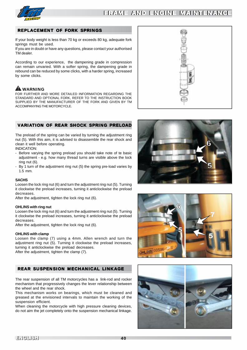
ENGLISHENGLISH 40
REPLACEMENT OF FORK SPRINGSREPLACEMENT OF FORK SPRINGSREPLACEMENT OF FORK SPRINGSREPLACEMENT OF FORK SPRINGSREPLACEMENT OF FORK SPRINGS
If your body weight is less than 70 kg or exceeds 80 kg, adequate forksprings must be used.If you are in doubt or have any questions, please contact your authorisedTM dealer.
According to our experience, the dampening grade in compressioncan remain unvaried. With a softer spring, the dampening grade inrebound can be reduced by some clicks, with a harder spring, increasedby some clicks.
WARNINGFOR FURTHER AND MORE DETAILED INFORMATION REGARDING THESTANDARD AND OPTIONAL FORK, REFER TO THE INSTRUCTION BOOKSUPPLIED BY THE MANUFACTURER OF THE FORK AND GIVEN BY TMACCOMPANYING THE MOTORCYCLE.
VVVVVARIAARIAARIAARIAARIATION OF REAR SHOCK SPRING PRELTION OF REAR SHOCK SPRING PRELTION OF REAR SHOCK SPRING PRELTION OF REAR SHOCK SPRING PRELTION OF REAR SHOCK SPRING PRELOOOOOADADADADAD
The preload of the spring can be varied by turning the adjustment ringnut (5). With this aim, it is advised to disassemble the rear shock andclean it well before operating.INDICATION:- Before varying the spring preload you should take note of te basic
adjustment - e.g. how many thread turns are visible above the lockring nut (6).
- By 1 turn of the adjustment ring nut (5) the spring pre-load varies by1.5 mm.
SACHSLoosen the lock ring nut (6) and turn the adjustment ring nut (5). Turningit clockwise the preload increases, turning it anticlockwise the preloaddecreases.After the adjustment, tighten the lock ring nut (6).
OHLINS with ring nutLoosen the lock ring nut (6) and turn the adjustment ring nut (5). Turningit clockwise the preload increases, turning it anticlockwise the preloaddecreases.After the adjustment, tighten the lock ring nut (6).
OHLINS with clampLoosen the clamp (7) using a 4mm. Allen wrench and turn theadjustment ring nut (5). Turning it clockwise the preload increases,turning it anticlockwise the preload decreases.After the adjustment, tighten the clamp (7).
REAR SUSPENSION MECHANICAL LINKAGEREAR SUSPENSION MECHANICAL LINKAGEREAR SUSPENSION MECHANICAL LINKAGEREAR SUSPENSION MECHANICAL LINKAGEREAR SUSPENSION MECHANICAL LINKAGE
The rear suspension of all TM motorcycles has a link-rod and rockermechanism that progressively changes the lever relationship betweenthe wheel and the rear shock.This mechanism works on bearings, which must be cleaned andgreased at the envisioned intervals to maintain the working of thesuspension efficient.When cleaning the motorcycle with high pressure cleaning devices,do not aim the jet completely onto the suspension mechanical linkage.
FRAME AND ENGINE MAINTENANCEFRAME AND ENGINE MAINTENANCEFRAME AND ENGINE MAINTENANCEFRAME AND ENGINE MAINTENANCEFRAME AND ENGINE MAINTENANCEFRAME AND ENGINE MAINTENANCEFRAME AND ENGINE MAINTENANCEFRAME AND ENGINE MAINTENANCEFRAME AND ENGINE MAINTENANCEFRAME AND ENGINE MAINTENANCE
7
5

ENGLISHENGLISHENGLISH41
3
2
14
5
6
CHECK CHAIN TENSIONCHECK CHAIN TENSIONCHECK CHAIN TENSIONCHECK CHAIN TENSIONCHECK CHAIN TENSION
Put the motorcycle onto the central stand to control chain tension.Push the chain upwards to the end of the drive chain slider.The upper part of the chain (A) must be taught (see photo). The distancebetween the chain and rear fork must be about. 10-15 mm. Adjust thetension, if necessary.
- IF THE CHAIN IS TOO TIGHT , THE FINAL TANSMISSION COMPONENTS(CHAIN, GEARBOX AND REAR WHEEL BEARINGS) ARE GREATLYSTRESSED. AS WELL AS A PREMATURE WEAR, IN EXTREME SITUATIONSTHE CHAIN OR GEARBOX DRIVEN SHAFT MAY BREAK.
- IF, HOWEVER, CHAIN TENSION IS INSUFFICIENT, IT CAN EXIT FROM THESPROCKET AND LOCK THE REAR WHEEL OR DAMAGE THE ENGINE.
- IN BOTH CASES IT IS EASY TO LOOSE CONTROL OF THE MOTORCYCLE.
ADJUSTMENT OF CHAIN TENSIONADJUSTMENT OF CHAIN TENSIONADJUSTMENT OF CHAIN TENSIONADJUSTMENT OF CHAIN TENSIONADJUSTMENT OF CHAIN TENSION(ALL MODELS EXCEPT SMM)(ALL MODELS EXCEPT SMM)(ALL MODELS EXCEPT SMM)(ALL MODELS EXCEPT SMM)(ALL MODELS EXCEPT SMM)
Loosen the wheel axle nut (1), loosen the counter-nuts (2) and turn theadjustment bolts (3) to the left and to the right by the same amount. Toincrease chain tension, unscrew the adjustment bolts. To decreasechain tension, screw the adjustment bolts. Reach correct chain tension.For correct alignment of the rear wheel, the marks (4) on the right andleft chain-tensioner must aligned with respect to the reference markings(5). Tighten the adjustment screw counter-nuts. Before locking thewheel axle nut, check that the chain-tensioners (6) are laying on theheads of the adjustment bolts and that the rear wheel is aligned withthe front wheel.Tighten the wheel axle nut to 80 Nm.
ATTENTION- IF YOU DO NOT HAVE A DYNAMOMETRIC WRENCH FOR ASSEMBLING, HAVE
THE TIGHTENING TORQUE CHECKED BY A SPECIALISED TM WORKSHOP ASSOON AS POSSIBLE.A LOOSE WHEEL AXLE MAY CAUSE UNSTABLE DRIVING OF THEMOTORCYCLE.
DANGER
FRAME AND ENGINE MAINTENANCEFRAME AND ENGINE MAINTENANCEFRAME AND ENGINE MAINTENANCEFRAME AND ENGINE MAINTENANCEFRAME AND ENGINE MAINTENANCEFRAME AND ENGINE MAINTENANCEFRAME AND ENGINE MAINTENANCEFRAME AND ENGINE MAINTENANCEFRAME AND ENGINE MAINTENANCEFRAME AND ENGINE MAINTENANCE

ENGLISHENGLISH 42
8
7
ADJUSTMENT OF CHAIN TENSION (SMM)ADJUSTMENT OF CHAIN TENSION (SMM)ADJUSTMENT OF CHAIN TENSION (SMM)ADJUSTMENT OF CHAIN TENSION (SMM)ADJUSTMENT OF CHAIN TENSION (SMM)
Loosen both the locking screws(7) of the rear eccentric hub in a waythat the hub itself can turn around its axis.Using the relevant TM tool, code F50806 (8), turn the hub until correctchain tension is reached. Tighten the two locking screws to 30 Nm.Since the movement is an eccentric system, alignment of the rearwheel is unvaried and no further adjustment is required.At the same time, by turning the hub a slight variation in the height ofthe rear wheel axle may be verified and consequently of the rear part ofthe motorcycle. It is possible to compensate this, by varying theprojection of the fork legs from the upper clamp.For example, if the motorcycle, by effect of chain adjustment, has liftedby 5mm. at the rear, it is advised to decrease the projection of the forkrods by about 5mm. to also raise the front and restore the originallevelling of the motorcycle.It is advised to use the TM tool, code F50806, pairing with two M8screws and two nuts to turn the hub inserting the two screws into thetwo holes in the hub itself.
AAAAATTENTIONTTENTIONTTENTIONTTENTIONTTENTION- IF YOU DO NOT HAVE SUITABLE EXPERIENCE, IT IS ADVISED TO HAVE THE
OPERATION CARRIED OUT BY A SPECIALISED TM WORKSHOP.
CHAIN MAINTENANCECHAIN MAINTENANCECHAIN MAINTENANCECHAIN MAINTENANCECHAIN MAINTENANCE
Chain duration depends most of all on maintenance. Chains withoutO-rings must be regularly cleaned with petroleum and then immersedin warm chain oil or treated with chain spray. Maintenance of chainswith O-rings is reduced to a minimum. The best cleaning method isusing lots of water. Never use brushes or solvents to clean the chain.When the chain is dry, use a chain spray that is especially suitable forchains with O-rings.
DO NOT ALLOW THE LUBRICANT TO REACH THE REAR TYRE OR THE BRAKEDISC, OTHERWISE ADHERENCE TO THE GROUND OF THE REAR WHEEL ANDREAR BRAKE ACTION COULD BE NOTABLY REDUCED AND IT COULD BEEASY TO LOOSE CONTROL OF THE MOTORCYCLE.
WARNINGON MOUNTING THE CHAIN SPLIT LINK, THE CLOSED PART MUST BE IN THEDIRECTION OF MOVEMENT.
Always check both engine and rear wheel sprockets and drive sliderfor wear. If necessary, replace these parts.
DANGER
FRAME AND ENGINE MAINTENANCEFRAME AND ENGINE MAINTENANCEFRAME AND ENGINE MAINTENANCEFRAME AND ENGINE MAINTENANCEFRAME AND ENGINE MAINTENANCEFRAME AND ENGINE MAINTENANCEFRAME AND ENGINE MAINTENANCEFRAME AND ENGINE MAINTENANCEFRAME AND ENGINE MAINTENANCEFRAME AND ENGINE MAINTENANCE

ENGLISHENGLISHENGLISH43
CHAIN WEARCHAIN WEARCHAIN WEARCHAIN WEARCHAIN WEAR
To check chain wear follow carefully the instructions given below :put the gear into neutral, pull the upper part of the chain in an upwarddirection with a force of 10 - 15 kilogrammes (see figure). Now, measurethe distance of 18 links on the lower part of the chain. If the distanceexceeds 272 mm it is advised to replace the chain. The chains are notalways worn in a even way. For this reason the measurement must betaken in different points on the chain.
INDICATION:When a new chain is mounted, also replace the sprockets. A newchain wears more quickly on old and worn sprockets.
WARNINGWHEN THE CHAIN SPROCKETS ARE REPLACED, IT IS ADVISED TO MOUNT NEWSELF-LOCKING NUTS AND TO TIGHTEN WITH CROSS SEQUENCE.TIGHTENING TORQUE AT NUTS 35 NM.
BBBBBASIC INDICAASIC INDICAASIC INDICAASIC INDICAASIC INDICATIONS FOR TIONS FOR TIONS FOR TIONS FOR TIONS FOR TM DISC BRAKESTM DISC BRAKESTM DISC BRAKESTM DISC BRAKESTM DISC BRAKES
CALIPERS :The mounting system of the calipers of these models is “floating”, i.ethey are not rigidly joined to their support. The lateral compensationalways allows the pads to work in the best way on the discs. The brakecaliper fastening screws must be assembled using Loctite 243 andtightened at 25 Nm.The front calipers of the SMR/SMM/SMX models are an exception asthey are fixed-type.
PADS:The minimum thickness of the friction material cannot go under thelimit of 1mm.In case of replacement, it is advised always to use TM original spareparts for your motorcycle.
BRAKE DISCS:With wear the thickness of the brake disc is reduced in the contact areaof the pads (1). In the thinnest point (A) the brake disc may presentmax. wear of 0.4 mm with respect to original thickness. The originalthickness can be measured in point (B) outside of the contact area.Check wear in different points.
- BRAKE DISCS WITH WEAR EXCEEDING 0.4 MM ARE A RISK FOR SAFETY.WHEN THE LIMIT OF WEAR HAS BEEN REACHED, HAVE THE BRAKE DISCSREPLACED IMMEDIATELY.
- IT IS COMPULSORY TO HAVE THE BRAKE UNIT REPAIRED BY A TMAUTHORISED WORKSHOP.
DANGER
FRAME AND ENGINE MAINTENANCEFRAME AND ENGINE MAINTENANCEFRAME AND ENGINE MAINTENANCEFRAME AND ENGINE MAINTENANCEFRAME AND ENGINE MAINTENANCEFRAME AND ENGINE MAINTENANCEFRAME AND ENGINE MAINTENANCEFRAME AND ENGINE MAINTENANCEFRAME AND ENGINE MAINTENANCEFRAME AND ENGINE MAINTENANCE
A
B
1

ENGLISHENGLISH 44
BRAKE FLUID RESERVOIRS:The front and rear brake liquid reservoirs are dimensioned in a way thattopping-up is not necessary even if the brake pads are worn. In fact, whenthe pads are worn, the fluid in the hoses tends to occupy the space left by thesmall pistons, which have moved so that the pads always lay on the disc. Ifthe level of brake fluid falls below the minimum value, it indicates that thereis a leak in the braking system or brake pad wear is beyond accepted limits.
BRAKE FLUID:The braking system is filled by TM with top-quality DOT 4 brake fluid.We recommend that top-ups and complete replacement are carriedout using the same type of fluid (DOT 4).
HAVE THE BRAKE FLUID REPLACED AT LEAST ONCE A YEAR. IF YOU WASHTHE MOTORCYCLE FREQUENTLY, IT SHOULD BE REPLACED MORE OFTEN.THE BRAKE FLUID SOAKS WATER. IN OLD FLUID THEREFORE IT IS POSSIBLETHAT STEAM BUBBLES FORM EVEN AT LOW TEMPERATURES AND THEBRAKING SYSTEM DOES NOT WORK CORRECTLY.
FRONT BRAKE NISSIN PUMP (END/MX)FRONT BRAKE NISSIN PUMP (END/MX)FRONT BRAKE NISSIN PUMP (END/MX)FRONT BRAKE NISSIN PUMP (END/MX)FRONT BRAKE NISSIN PUMP (END/MX)
FRONT BRAKE LEVER ADJUSTMENTFRONT BRAKE LEVER ADJUSTMENTFRONT BRAKE LEVER ADJUSTMENTFRONT BRAKE LEVER ADJUSTMENTFRONT BRAKE LEVER ADJUSTMENTThe distance of thefront brak lever from the handlebar grip can be adjusted through theadjustment screw (1). Loosen the lock nut (2) and turn the screwclockwise to increase the distance, anticlockwise to reduce thedistance. Re-tighten the lock nut (2).
WARNINGAT THE END OF THE OPERATION VERIFY THAT THE FRONT BRAKE LEVER HASA FREE STROKE BEFORE THE BRAKE STARTS TO LOCK THE WHEEL AND THATTHE FRONT WHEEL CAN ROTATE FREELY WITH THE BRAKE LEVER AT REST. IFTHE FREE STROKE IS MISSING, PRESSURE IS FORMED IN THE BRAKING SYSTEMAND THE CONSEQUENCE CAN BE LACK OF FUNCTIONING OF THE FRONTWHEEL BRAKE DUE TO OVERHEATING OR BLOCKING OF THE WHEEL ITSELF.
CHECK FLUID LEVELCHECK FLUID LEVELCHECK FLUID LEVELCHECK FLUID LEVELCHECK FLUID LEVELThe reservoir is part of the front brake pump positioned on thehandlebar and has an inspection window (3): with the tank in thehorizontal position, the fluid level must never fall below the centrelineon the inspection window.
IF THE LEVEL OF BRAKE LIQUID FALLS BELOW THE MINIMUM VALUE, ITINDICATES A LEAK IN THE BRAKING SYSTEM OR CONSUMPTION OF BRAKEPADS BEYOND THE ACCEPTED LIMITS.
TOP-UP FRONT BRAKE FLUID (A)TOP-UP FRONT BRAKE FLUID (A)TOP-UP FRONT BRAKE FLUID (A)TOP-UP FRONT BRAKE FLUID (A)TOP-UP FRONT BRAKE FLUID (A)Remove the screws (4) and remove the lid (5) and the membrane (6).Place the front brake pump in a horizontal position and top-up thebrake fluid to 5 mm below the upper edge of the container. Re-mountmembrane, lid and screws. Wash any spilled brake fluid away withwater.Wash any spilled brake fluid away with water.
- KEEP BRAKE FLUID OUT OF THE REACH OF CHILDREN.- BRAKE FLUID MAY IRRITATE THE SKIN. DO NOT ALLOW IT TO TOUCH
SKIN OR EYES. IF THE BRAKE FLUID SHOULD ACCIDENTLY SPRAY INTOTHE EYES, RINSE WELL WITH WATER AND SEEK MEDICAL ASSISTANCE.
WARNING- DO NOT ALLOW BRAKE FLUID TO COME INTO CONTACT WITH PAINTED
PARTS, THE BRAKE FLUID CORRODES PAINT.- USE ONLY CLEAN BRAKE FLUID OUT OF A HERMETICALLY SEALED
CONTAINER.
DANGER
FRAME AND ENGINE MAINTENANCEFRAME AND ENGINE MAINTENANCEFRAME AND ENGINE MAINTENANCEFRAME AND ENGINE MAINTENANCEFRAME AND ENGINE MAINTENANCEFRAME AND ENGINE MAINTENANCEFRAME AND ENGINE MAINTENANCEFRAME AND ENGINE MAINTENANCEFRAME AND ENGINE MAINTENANCEFRAME AND ENGINE MAINTENANCE
2
1
3
5
6
4
DOT4
DANGER
DANGER

ENGLISHENGLISHENGLISH45
FRONT BRAKE BREMBO RADIAL PUMPFRONT BRAKE BREMBO RADIAL PUMPFRONT BRAKE BREMBO RADIAL PUMPFRONT BRAKE BREMBO RADIAL PUMPFRONT BRAKE BREMBO RADIAL PUMP (SMR/SMM/SMX) (SMR/SMM/SMX) (SMR/SMM/SMX) (SMR/SMM/SMX) (SMR/SMM/SMX)
FRONT BRAKE LEVER ADJUSTMENTFRONT BRAKE LEVER ADJUSTMENTFRONT BRAKE LEVER ADJUSTMENTFRONT BRAKE LEVER ADJUSTMENTFRONT BRAKE LEVER ADJUSTMENTThe distance of the front brake lever from the handlebar grip can beadjusted through the adjustment knob (1). Turning it clockwise thedistance increases, turning it anticlockwise the distance decreases.
WARNINGAT THE END OF THE OPERATION VERIFY THAT THE FRONT BRAKE LEVER HASA FREE STROKE BEFORE THE BRAKE STARTS TO LOCK THE WHEEL AND THATTHE FRONT WHEEL CAN ROTATE FREELY WITH THE BRAKE LEVER AT REST. IFTHE FREE STROKE IS MISSING, PRESSURE IS FORMED IN THE BRAKING SYSTEMAND THE CONSEQUENCE CAN BE LACK OF FUNCTIONING OF THE FRONTWHEEL BRAKE DUE TO OVERHEATING OR BLOCKING OF THE WHEEL ITSELF.
CHECK FLUID LEVELCHECK FLUID LEVELCHECK FLUID LEVELCHECK FLUID LEVELCHECK FLUID LEVELThe reservoir (2) is transparent and allows you to check for the fluidlevel: with the reservoir standing up, the fluid level must be alwaysbetween MAX and MIN remarks.
IF THE BRAKE FLUID LEVEL FALLS BELOW THE MINIMUM VALUE, ITINDICATES A LEAKING IN THE BREAKING SYSTEM OR CONSUMPTION OFBRAKE PADS BEYOND THE ACCEPTABLE LIMIT.
TOP-UP FRONT BRAKE FLUID (A)TOP-UP FRONT BRAKE FLUID (A)TOP-UP FRONT BRAKE FLUID (A)TOP-UP FRONT BRAKE FLUID (A)TOP-UP FRONT BRAKE FLUID (A)Unscrew and remove the cap (3) and the membrane (4). Keep thereservoir standing up and top-up the brake fluid to the MAX remark onthe reservoir. Reassemble the membrane, the cap and tighten.Washany spilled brake fluid away with water.
- KEEP BRAKE FLUID OUT OF THE REACH OF CHILDREN.- BRAKE FLUID MAY IRRITATE THE SKIN. DO NOT ALLOW IT TO TOUCH
SKIN OR EYES. IF THE BRAKE FLUID SHOULD ACCIDENTLY SPRAY INTOTHE EYES, RINSE WELL WITH WATER AND SEEK MEDICAL ASSISTANCE.
WARNING- DO NOT ALLOW BRAKE FLUID TO COME INTO CONTACT WITH PAINTED
PARTS, THE BRAKE FLUID CORRODES PAINT.- USE ONLY CLEAN BRAKE FLUID OUT OF A HERMETICALLY SEALED
CONTAINER.
CHECK FRCHECK FRCHECK FRCHECK FRCHECK FRONT BRAKE PONT BRAKE PONT BRAKE PONT BRAKE PONT BRAKE PADSADSADSADSADS
The brake pads can be checked from below. The thickness of the padfriction material must not be less than1 mm.
THE THICKNESS OF THE BRAKE PAD THICKNESS MATERIAL MUST NOT BELESS THAN 1 MM, OTHERWISE THERE COULD BE A FAULT IN THE BRAKES.IN THE INTEREST OF YOUR SAFETY HAVE THE THE PADS REPLACED INTIME.
WARNINGIF THE BRAKE PADS ARE REPLACED TOO LATE AND ARE COMPLETELY WORN,THE STEELPARTS OF THE PADS RUB ON THE DISC. THIS LEADS TO A NOTABLEDECREASE IN THE BRAKING EFFECT AND DAMAGE OF THE BRAKE DISC.
DANGER
FRAME AND ENGINE MAINTENANCEFRAME AND ENGINE MAINTENANCEFRAME AND ENGINE MAINTENANCEFRAME AND ENGINE MAINTENANCEFRAME AND ENGINE MAINTENANCEFRAME AND ENGINE MAINTENANCEFRAME AND ENGINE MAINTENANCEFRAME AND ENGINE MAINTENANCEFRAME AND ENGINE MAINTENANCEFRAME AND ENGINE MAINTENANCE
2
3
4
1
min 1 mm
DANGER

ENGLISHENGLISH 46
REPLAREPLAREPLAREPLAREPLACEMENT OF FRCEMENT OF FRCEMENT OF FRCEMENT OF FRCEMENT OF FRONT BRAKE PONT BRAKE PONT BRAKE PONT BRAKE PONT BRAKE PADS ADS ADS ADS ADS (A)(A)(A)(A)(A)
FOR ALL MODELS WITH FLOATING CALIPER (END/MX)Push the brake caliper towards the disc, in a way that the brake pistonsreach their base position. Remove the safety devices (1), extract thepin (2) and remove the pads from the caliper. Use compressed air toclean the brake caliper and the caliper support, check that the drivingpin seals are not damaged and, if necessary, grease them.Mount the right brake pad and fix it with the pin. Mount the left brake padand insert the pin until it stops. Mount the safety devices. Duringmounting of the pads, ensure that the protection sheet-steel in thecaliper support and the leaf spring are correctly positioned.
FOR ALL MODELS WITH FIXED CALIPER (SMR/SMM/SMX)RADIAL COUPLING - Unscrew the two screws M10 (3) and remove thecaliper from the fork shoe. Press the two hooks (4) one at a time torelease and slide the retainer pins (5) out. Lever on each pair of padsto allow the pistons to go back to their seat. Extract the worn pads andinsert the new ones. Repeat the operation for the other pair of pads.Press the two hooks down and re-insert the pins: be sure that they arefully inserted, have their play and are correctly attached. Reassemblethe caliper and tighten the M10 screws at 40Nm.
AXIAL COUPLING - Unscrew the two M8 screws (6) and remove thecaliper. Lever the pads to allow the pistons to go back into their seat,then remove the safety pin (7), slide the pin (8) out and then extract thepads, paying attention to the laminated spring (9). Remount the newpads, the laminate, the pin and the safety retainer, then reassemblethe caliper and tighten the M8 screws at 25 Nm.
WARNING- FOR ALL MODELS: WHEN THE CALIPER PISTONS ARE PUSHED BACK TO
THEIR SEAT TO PROVIDE ROOM FOR THE NEW PADS, PAY ATTENTION THATTHE FLUID CONTAINED IN THE RESERVOIR HAS THE SPACE TO EXPAND. DONOT WORK WITHOUT THE CAP MOUNTED, OTHERWISE THE FLUID COULDOVERFLOW AND DAMAGE PARTS OF THE MOTORCYCLE.
- THE BRAKE DISC MUST ALWAYS BE KEPT FREE FROM OIL AND GREASE.OTHERWISE THE BRAKING EFFECT WOULD BE GREATLY REDUCED.
- AFTER MOUNTING, CHECK THAT THE SAFETY DEVICES ARE CORRECTLYPOSITIONED . AFTER EVERY INTERVENTION ON THE BRAKING SYSTEMACTIVATE THE FRONT BRAKE LEVER AND THE REAR BRAKE PEDAL TOMAKE THE PADS ADHERE TO THE DISC AND TO RESTORE THE CORRECTADJUSTMENT OF PLAY.
DANGER
FRAME AND ENGINE MAINTENANCEFRAME AND ENGINE MAINTENANCEFRAME AND ENGINE MAINTENANCEFRAME AND ENGINE MAINTENANCEFRAME AND ENGINE MAINTENANCEFRAME AND ENGINE MAINTENANCEFRAME AND ENGINE MAINTENANCEFRAME AND ENGINE MAINTENANCEFRAME AND ENGINE MAINTENANCEFRAME AND ENGINE MAINTENANCE
3
45
6 7
8
9
2
1

ENGLISHENGLISHENGLISH47
MODIFICATION OF REAR BRAKE PEDMODIFICATION OF REAR BRAKE PEDMODIFICATION OF REAR BRAKE PEDMODIFICATION OF REAR BRAKE PEDMODIFICATION OF REAR BRAKE PEDALALALALAL BASE POSITION (A) BASE POSITION (A) BASE POSITION (A) BASE POSITION (A) BASE POSITION (A)
The base position of the rear brake pedal can be modified in thefollowing way: loosen counter-nut M6 (1) fork side, turn the adjustmentscrews by acting on the hexagonal head (2). Once the ideal positionhas been found, tighten the counter-nut.The pedal free play is given by the stroke of the pump piston; check thatthe pedal has a free play of about 1.5cm before starting to brake.
WARNINGIF THERE IS NO FREE PLAY, PRESSURE DEVELOPS IN THE BRAKING SYSTEMAND CONSEQUENTLY THE REAR WHEEL IS BRAKED. THE BRAKING SYSTEMOVERHEATS AND IN EXTREME CASE IT WILL NOT WORK.
CHECK REAR BRAKE FLUID LEVELCHECK REAR BRAKE FLUID LEVELCHECK REAR BRAKE FLUID LEVELCHECK REAR BRAKE FLUID LEVELCHECK REAR BRAKE FLUID LEVEL
ALL THE MODELSThe reservoir for the rear disc brake fluid is incorporated into the rearbrake pump. When the motorcycle is in a vertical position, the levelmust always be over half way on the window (3) positioned on the bodyof the pump.
IF THE LEVEL OF THE BRAKE FLUID FALLS BELOW THE MINIMUM LEVEL,IT INDICATES A LEAK IN THE BRAKING SYSTEM OR COMPLETECONSUMPTION OF THE BRAKE PADS.
TOP-UP REAR BRAKE FLUID (A)TOP-UP REAR BRAKE FLUID (A)TOP-UP REAR BRAKE FLUID (A)TOP-UP REAR BRAKE FLUID (A)TOP-UP REAR BRAKE FLUID (A)
ALL THE MODELSAs soon as the level of rear brake fluid reaches the centreline on thewindow situated on the pump, it must be topped-up. Unscrew the twoscrews (4) and remove the lid. Top-up with DOT4 brake fluid to the topof the window. Remount the lid and tighten the screws.Wash any spilled brake fluid away with water
- NEVER USE DOT5 BRAKE FLUID! IT IS A PURPLE SILICONE OIL-BASEDBRAKE FLUID. IT REQUIRES THE USE OF SPECIAL SEALS AND HOSES
- KEEP THE BRAKE FLUID OUT OF CHIDREN’S REACH.- THE BRAKE FLUID CAN IRRITATE THE SKIN. DO NOT ALLOW IT TO TOUCH
THE SKIN OR EYES. IF THE BRAKE FLUID SHOULD SPRAY INTO THE EYESRINSE WELL WITH WATER AND SEEK MEDICAL ATTENTION
WARNINGWARNINGWARNINGWARNINGWARNING- DO NOT ALLOW BRAKE FLUID TO COME INTO CONTACT WITH PAINTED
PARTS. BRAKE FLUID CORRODES PAINT !- USE ONLY CLEAN BRAKE FLUID FROM A HERMETICALLY SEALED
CONTAINER.
DANGER
DANGER
FRAME AND ENGINE MAINTENANCEFRAME AND ENGINE MAINTENANCEFRAME AND ENGINE MAINTENANCEFRAME AND ENGINE MAINTENANCEFRAME AND ENGINE MAINTENANCEFRAME AND ENGINE MAINTENANCEFRAME AND ENGINE MAINTENANCEFRAME AND ENGINE MAINTENANCEFRAME AND ENGINE MAINTENANCEFRAME AND ENGINE MAINTENANCE

ENGLISHENGLISH 48
CHECK REAR BRAKE PCHECK REAR BRAKE PCHECK REAR BRAKE PCHECK REAR BRAKE PCHECK REAR BRAKE PADSADSADSADSADS
The brake pads must be controlled from the rear side. The thicknessof the pad friction material must not be less than 1 mm.
AT THE THINNEST POINT, THE THICKNESS OF THE BRAKE PAD FRICTIONMATERIAL MUST NOT BE LESS THAN 1 MM, OTHERWISE A FAULT COULDOCCUR IN THE BRAKES. IN THE INTEREST OF YOUR SAFETY HAVE THE PADSREPLACED IN TIME.
WARNINGIF THE BRAKE PADS ARE REPLACED TOO LATE SO THAT THE FRICTIONMATERIAL IS COMPLETELY CONSUMED, THE STEEL PARTS OF THE PADS RUBON THE DISC. THIS LEADS TO A NOTEWORTHY DECREASE OF THE BRAKINGEFFECT AND DAMAGE OF THE BRAKE DISC.
REPLAREPLAREPLAREPLAREPLACEMENT OF REAR BRAKE PCEMENT OF REAR BRAKE PCEMENT OF REAR BRAKE PCEMENT OF REAR BRAKE PCEMENT OF REAR BRAKE PADS ADS ADS ADS ADS (A) (A) (A) (A) (A)
FOR ALL MODELS WITH FLOATING CALIPER (END/MX/SMR/SMX)Push the brake caliper (1) towards the disc, until the piston reaches itsbase position. Remove the cap (2) using a screwdriver, unscrew thepin (3) and slide the brake pad out. Pay attention to the plates (4)placed between the pads: these must be remounted accurately. Cleanthe brake caliper with compressed air and check that the drive pinsheaths are not damaged.Remount the new pads, paying attention to the positioning of the plates,insert the pin, re-screw it and tighten. Remount the tap using ascrewdriver. Tighten well.
FOR ALL MODELS WITH FIXED CALIPER (SMM)Remove the safety ring (5) and slide the pin out (6) hitting with apin-puller with 4mm. diameter on the same side where the safetyring is found.
- THE BRAKE DISC MUST ALWAYS BE PERFECTLY CLEAN FROM OIL ANDGREASE. OTHERWISE THE BRAKING EFFECT WOULD BE GREATLYREDUCED.
- AFTER MOUNTING, CHECK THAT THE SAFETY DEVICES ARE POSITIONEDCORRECTLY.
- AFTER EVERY INTERVENTION ON THE BRAKING SYSTEM, ACTIVATE THEFRONT BRAKE LEVER AND THE REAR BRAKE PEDAL TO MAKE THE PADSADHERE TO THE DISC AND TO RESTORE THE CORRECT ADJUSTMENTOF PLAY.
DISASSEMBLDISASSEMBLDISASSEMBLDISASSEMBLDISASSEMBLY Y Y Y Y AND AND AND AND AND ASSEMBLASSEMBLASSEMBLASSEMBLASSEMBLY OF Y OF Y OF Y OF Y OF THE FRTHE FRTHE FRTHE FRTHE FRONTONTONTONTONTWHEELWHEELWHEELWHEELWHEEL
Position the motorcycle with the frame cradle on a stand in a way thatthe front wheel does not touch the ground.Loosen the flanged nut (7), loosen the fastening screws (8) on the leftand right fork shoes, finish unscrewing the flanged nut.Holding the front wheel still, slide the wheel axle out.If necessary, to help the wheel axle to exit, strike lightly with a mallet(hammer with plastic ends) on the threaded end of the axle itself.Alternatively, use a normal hammer and place a piece of wood between.NEVER USE THE HAMMER DIRECTLY ON THE AXLE, YOU RISK TODAMAGE THE AXLE IRREVERSIBLY.Slide the front wheel carefully out of the fork.
DANGER
DANGER
FRAME AND ENGINE MAINTENANCEFRAME AND ENGINE MAINTENANCEFRAME AND ENGINE MAINTENANCEFRAME AND ENGINE MAINTENANCEFRAME AND ENGINE MAINTENANCEFRAME AND ENGINE MAINTENANCEFRAME AND ENGINE MAINTENANCEFRAME AND ENGINE MAINTENANCEFRAME AND ENGINE MAINTENANCEFRAME AND ENGINE MAINTENANCE
6 5
87
4
23
1
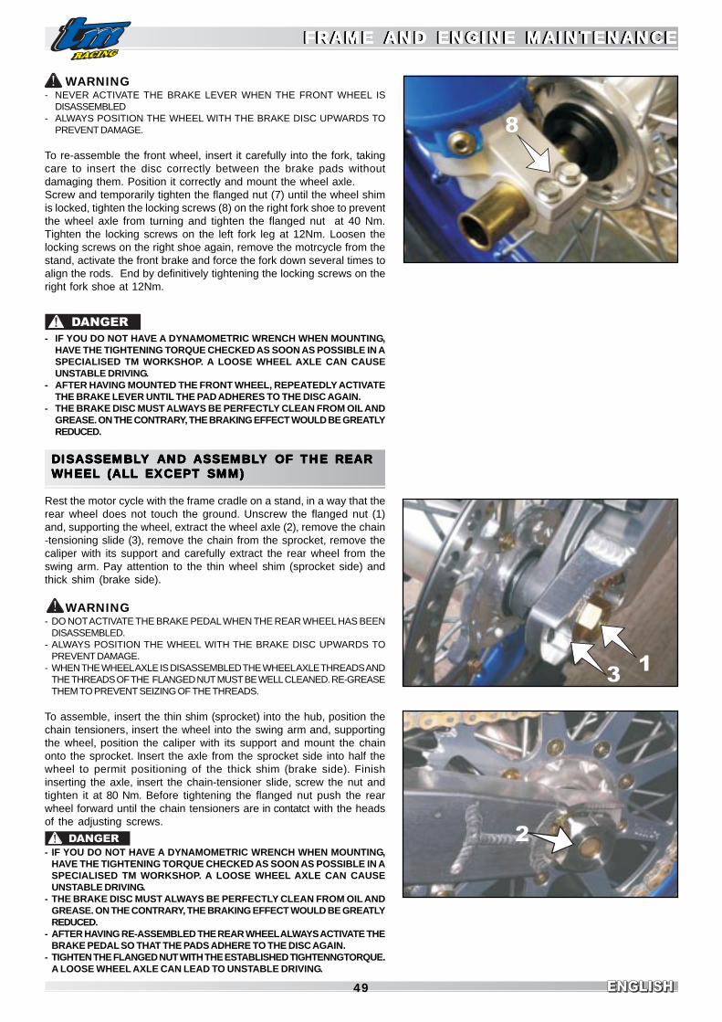
ENGLISHENGLISHENGLISH49
WARNING- NEVER ACTIVATE THE BRAKE LEVER WHEN THE FRONT WHEEL IS
DISASSEMBLED- ALWAYS POSITION THE WHEEL WITH THE BRAKE DISC UPWARDS TO
PREVENT DAMAGE.
To re-assemble the front wheel, insert it carefully into the fork, takingcare to insert the disc correctly between the brake pads withoutdamaging them. Position it correctly and mount the wheel axle.Screw and temporarily tighten the flanged nut (7) until the wheel shimis locked, tighten the locking screws (8) on the right fork shoe to preventthe wheel axle from turning and tighten the flanged nut at 40 Nm.Tighten the locking screws on the left fork leg at 12Nm. Loosen thelocking screws on the right shoe again, remove the motrcycle from thestand, activate the front brake and force the fork down several times toalign the rods. End by definitively tightening the locking screws on theright fork shoe at 12Nm.
- IF YOU DO NOT HAVE A DYNAMOMETRIC WRENCH WHEN MOUNTING,HAVE THE TIGHTENING TORQUE CHECKED AS SOON AS POSSIBLE IN ASPECIALISED TM WORKSHOP. A LOOSE WHEEL AXLE CAN CAUSEUNSTABLE DRIVING.
- AFTER HAVING MOUNTED THE FRONT WHEEL, REPEATEDLY ACTIVATETHE BRAKE LEVER UNTIL THE PAD ADHERES TO THE DISC AGAIN.
- THE BRAKE DISC MUST ALWAYS BE PERFECTLY CLEAN FROM OIL ANDGREASE. ON THE CONTRARY, THE BRAKING EFFECT WOULD BE GREATLYREDUCED.
DISASSEMBLDISASSEMBLDISASSEMBLDISASSEMBLDISASSEMBLY Y Y Y Y AND AND AND AND AND ASSEMBLASSEMBLASSEMBLASSEMBLASSEMBLY OF Y OF Y OF Y OF Y OF THE REARTHE REARTHE REARTHE REARTHE REARWHEEL (ALL EXCEPT SMM)WHEEL (ALL EXCEPT SMM)WHEEL (ALL EXCEPT SMM)WHEEL (ALL EXCEPT SMM)WHEEL (ALL EXCEPT SMM)
Rest the motor cycle with the frame cradle on a stand, in a way that therear wheel does not touch the ground. Unscrew the flanged nut (1)and, supporting the wheel, extract the wheel axle (2), remove the chain-tensioning slide (3), remove the chain from the sprocket, remove thecaliper with its support and carefully extract the rear wheel from theswing arm. Pay attention to the thin wheel shim (sprocket side) andthick shim (brake side).
WARNING- DO NOT ACTIVATE THE BRAKE PEDAL WHEN THE REAR WHEEL HAS BEEN
DISASSEMBLED.- ALWAYS POSITION THE WHEEL WITH THE BRAKE DISC UPWARDS TO
PREVENT DAMAGE.- WHEN THE WHEEL AXLE IS DISASSEMBLED THE WHEEL AXLE THREADS AND
THE THREADS OF THE FLANGED NUT MUST BE WELL CLEANED. RE-GREASETHEM TO PREVENT SEIZING OF THE THREADS.
To assemble, insert the thin shim (sprocket) into the hub, position thechain tensioners, insert the wheel into the swing arm and, supportingthe wheel, position the caliper with its support and mount the chainonto the sprocket. Insert the axle from the sprocket side into half thewheel to permit positioning of the thick shim (brake side). Finishinserting the axle, insert the chain-tensioner slide, screw the nut andtighten it at 80 Nm. Before tightening the flanged nut push the rearwheel forward until the chain tensioners are in contatct with the headsof the adjusting screws.
DANGER
- IF YOU DO NOT HAVE A DYNAMOMETRIC WRENCH WHEN MOUNTING,HAVE THE TIGHTENING TORQUE CHECKED AS SOON AS POSSIBLE IN ASPECIALISED TM WORKSHOP. A LOOSE WHEEL AXLE CAN CAUSEUNSTABLE DRIVING.
- THE BRAKE DISC MUST ALWAYS BE PERFECTLY CLEAN FROM OIL ANDGREASE. ON THE CONTRARY, THE BRAKING EFFECT WOULD BE GREATLYREDUCED.
- AFTER HAVING RE-ASSEMBLED THE REAR WHEEL ALWAYS ACTIVATE THEBRAKE PEDAL SO THAT THE PADS ADHERE TO THE DISC AGAIN.
- TIGHTEN THE FLANGED NUT WITH THE ESTABLISHED TIGHTENNGTORQUE.A LOOSE WHEEL AXLE CAN LEAD TO UNSTABLE DRIVING.
DANGER
FRAME AND ENGINE MAINTENANCEFRAME AND ENGINE MAINTENANCEFRAME AND ENGINE MAINTENANCEFRAME AND ENGINE MAINTENANCEFRAME AND ENGINE MAINTENANCEFRAME AND ENGINE MAINTENANCEFRAME AND ENGINE MAINTENANCEFRAME AND ENGINE MAINTENANCEFRAME AND ENGINE MAINTENANCEFRAME AND ENGINE MAINTENANCE
2
13
7
8

ENGLISHENGLISH 50
DISASSEMBLDISASSEMBLDISASSEMBLDISASSEMBLDISASSEMBLY Y Y Y Y AND AND AND AND AND ASSEMBLASSEMBLASSEMBLASSEMBLASSEMBLY OF REARY OF REARY OF REARY OF REARY OF REAR WHEEL (SMM) WHEEL (SMM) WHEEL (SMM) WHEEL (SMM) WHEEL (SMM)
Rest the motorcycle with the frame cradle on a stand, in a way that therear wheel does not touch the ground. Cut the safety binding (6), slideout the clasp (7) and unscrew the wheel nut M50x1.5(8). Pay attentionto the conical shim (9) placed between the nut and ring. Extract thewheel carefully.
WARNING- WHEN THE WHEEL NUT IS DISASSEMBLED, THE SHAFT AND NUT THREADS
MUST BE CLEANED CAREFULLY. RE-GREASE THEM TO PREVENT SEIZINGOF THE THREADS.
To assemble, proceed in the opposite direction, tightening the M50x1.5wheel nut at 185 Nm. Remount the clasp and re-make the safetybinding.
- DO NOT FORGET TO CARRY OUT THE SAFETY BINDING AT THE ENDS OFTHE CLASP
- IF YOU DO NOT HAVE A DYNAMOMETRIC WRENCH WHEN MOUNTING,HAVE THE TIGHTENING TORQUE CHECKED AS SOON AS POSSIBLE IN ASPECIALISED TM WORKSHOP. A LOOSE WHEEL AXLE CAN CAUSEUNSTABLE DRIVING.
- THE BRAKE DISC MUST ALWAYS BE PERFECTLY CLEAN FROM OIL ANDGREASE. ON THE CONTRARY, THE BRAKING EFFECT WOULD BE GREATLYREDUCED.
- AFTER HAVING RE-ASSEMBLED THE REAR WHEEL ALWAYS ACTIVATETHE BRAKE PEDAL SO THAT THE PADS ADHERE TO THE DISC AGAIN.
CHECK SPOKE TENSIONCHECK SPOKE TENSIONCHECK SPOKE TENSIONCHECK SPOKE TENSIONCHECK SPOKE TENSION
Correct tension of the spokes is very important for the stability of thewheel and therefore safety on the road. An insufficiently taught spokeleads to unbalancing of the wheel and in brief time loosening of otherspokes. Regularly check the tension of the spokes, particularly on newmotorcycles. Briefly hit every spoke with the end of a screwdriver (seephoto): the spoke should produce a clear sound. Hollow sounds meanloose spokes. In this case you must have the spokes adjusted in aspecialised workshop. The wheel must also be centred.
- IF YOU CONTINUE TRAVELLING WITH INSUFFICIENTLY TIGHT SPOKES,THEY MAY TEAR CAUSING PROBLEMS OF INSTABILITY.
- EXCESSIVELY TIGHT SPOKES MAY TEAR DUE TO LOCAL OVERLOADING.
DANGER
DANGER
FRAME AND ENGINE MAINTENANCEFRAME AND ENGINE MAINTENANCEFRAME AND ENGINE MAINTENANCEFRAME AND ENGINE MAINTENANCEFRAME AND ENGINE MAINTENANCEFRAME AND ENGINE MAINTENANCEFRAME AND ENGINE MAINTENANCEFRAME AND ENGINE MAINTENANCEFRAME AND ENGINE MAINTENANCEFRAME AND ENGINE MAINTENANCE
9
6 7
8

ENGLISHENGLISHENGLISH51
TYRES, TYRE PRESSURETYRES, TYRE PRESSURETYRES, TYRE PRESSURETYRES, TYRE PRESSURETYRES, TYRE PRESSURE
The type, the state and the pressure of the tyres condition themotorcycle’s behaviour on the road and they must be checked beforeevery journey.- The dimension of the tyres is indicated in the technical data and in
the registration paper.- The state of the tyres must be controlled before every journey.
Check the tyres by verifying that they are not cut, have nails or othersharp objects pushed into them.Regarding the minimum depth of the profile, respect the regulationsin force in your country. We recommend that the tyres are changed atthe latest, when the profile has reached a depth of 2 mm.
- The tyre air pressure must be checked regularly when the tyres are“cold”. Correct adjustment of the pressure guarantees optimalcomfort when travelling and maximum duration of the tyre.
- HAVE EXCLUSIVELY TYRES OF APPROVED TYPE AND DIMENSIONSMOUNTED ON YOUR VEHICLE AND HOWEVER ESTABLISHED BY TM.DIFFERENT TYRES CAN NEGATIVELY CONDITION THE BEHAVIOUR OFTHE MOTORCYCLE ON THE ROAD AND BE THE CAUSE OF FINESENVISIONED BY THE REGULATIONS IN FORCE IN YOUR COUNTRY .
- TO GUARANTEE YOUR SAFETY AND THAT OF OTHERS, DAMAGED TYRESMUST BE REPLACED IMMEDIATELY.
- EXCESSIVELY WORN TYRES NEGATIVELY CONDITION THE BEHAVIOUROF THE MOTORCYCLE, MOST OF ALL ON WET SURFACES.
- INCORRECT PRESSURE LEADS TO ANOMALOUS WEAR ANDOVERHEATING OF THE TYRE.
CHECK ADJUSTMENT OF MAGNETIC SENSORCHECK ADJUSTMENT OF MAGNETIC SENSORCHECK ADJUSTMENT OF MAGNETIC SENSORCHECK ADJUSTMENT OF MAGNETIC SENSORCHECK ADJUSTMENT OF MAGNETIC SENSORFOR FOR FOR FOR FOR TTTTTAAAAACHOMETER (A)CHOMETER (A)CHOMETER (A)CHOMETER (A)CHOMETER (A)
In all the versions the magnetic sensor is located on the rear wheel.
END/SMR - The distance between the head of the screws (2) and thesensor (1) must be 2-4mm. If not, the tachometer may not workproperly. The distance of the sensor is adjusted by the shim (3). Do notremove it, otherwise the sensor may hit the screws and get damaged.
SMM - The distance between the brake disc side face (4) and thesensor (1) must be 2-4mm. If not, the tachometer may not work properly.The distance is adjusted by the shim (3). Do not remove it, otherwisethe sensor may hit the disc side face (4) and get damaged.
BABABABABATTERY (END/MX/SMR/SMM/SMX)TTERY (END/MX/SMR/SMM/SMX)TTERY (END/MX/SMR/SMM/SMX)TTERY (END/MX/SMR/SMM/SMX)TTERY (END/MX/SMR/SMM/SMX)(ALL MODELS WITH E.S.)(ALL MODELS WITH E.S.)(ALL MODELS WITH E.S.)(ALL MODELS WITH E.S.)(ALL MODELS WITH E.S.)
The saddle must be removed to access the battery.The battery does not require maintenance.It is not necessary to check the level of the electrolyte or top-up withwater.The battery poles only must be cleaned and, if necessary, slightlygreased using grease that does not contain acids.Battery disassembly:First remove the negative pole and then the positive pole from thebattery.Disconnect the elastic stripes (5).Remove the battery.When assembling the battery, place it with the poles pointing back-wards (see figure), first connect the positive pole and then the nega-tive pole to the battery.
DANGER
FRAME AND ENGINE MAINTENANCEFRAME AND ENGINE MAINTENANCEFRAME AND ENGINE MAINTENANCEFRAME AND ENGINE MAINTENANCEFRAME AND ENGINE MAINTENANCEFRAME AND ENGINE MAINTENANCEFRAME AND ENGINE MAINTENANCEFRAME AND ENGINE MAINTENANCEFRAME AND ENGINE MAINTENANCEFRAME AND ENGINE MAINTENANCE
TYRE PRESSURETYRE PRESSURETYRE PRESSURETYRE PRESSURETYRE PRESSURETYRE PRESSURETYRE PRESSURETYRE PRESSURETYRE PRESSURETYRE PRESSURE
FRONTFRONTFRONTFRONTFRONT REARREARREARREARREAR
Off-road
Road, rider only
1.1 bar
1.7 bar
1.1 bar
1.7 bar
1
3
4
1
2
3
5
END/SMR
SMM

ENGLISHENGLISH 52
2
DANGER
- IF FOR SOME REASON THE ELECTROLYTE (SULPHURIC ACID) SHOULDESCAPE FROM THE BATTERY, BE VERY CAREFUL.THE ELECTROLYTE CAN CAUSE SERIOUS BURNS.
- ON CONTACT WITH THE SKIN, RINSE WELL WITH WATER- IF DROPS OF THE ELECTROLYTE ENTER INTO THE EYES, RINSE FOR AT
LEAST 15 MINUTES WITH WATER AND CONSULT A DOCTORIMMEDIATELY.
- EVEN IF THE BATTERY IS SEALED, IT IS POSSIBLE THAT EXPLOSIVEGASES MAY COME OUT. KEEP THE BATTERY AWAY FROM SPARKS ORFLAMES.
- KEEP FAULTY BATTERIES AWAY FROM CHILDREN AND DISPOSE OF THEMIN THE CORRECT MANNER.
WARNING- THE CLOSURE STRIP (2) MUST NOT BE REMOVED, AS OTHERWISE THE
REGULATOR-RECTIFIER WOULD BE DESTROYED.- THE BATTERY MUST BE MOUNTED WITH THE POLES IN FRONT (AS IN THE
FIGURE), IF IT IS MOUNTED IN THE OPPOSITE DIRECTION, THE ELECTROLYTEMAY COME OUT!
PRESERVATION:If the motorcycle is kept at a standstill for a long time, remove thebattery and charge it. Keep it at at temperature of 0-35°C away fromdirect sunlight.
BBBBBAAAAATTERTTERTTERTTERTTERY CHARY CHARY CHARY CHARY CHARGEGEGEGEGE
Remove the battery and determine if it is charged or not. To do thischeck the voltage between the poles using a voltmetre (rest voltage).To obtain a correct measurement, the battery must not be charged ordischarged for at least 30 minutes before the measurement is taken.
If it is not possible to determine the charge, the battery can be chargedfor a maximum of 10 hours with 0.5 ampere and max. 14.4 volt.
WARNING- THE CLOSURE STRIP MUST NOT BE REMOVED, AS IT WOULD BE DAMAGED.- TO RECHARGE, FIRST CONNECT THE BATTERY TO THE BATTERY CHARGER,
THEN SWITCH THE BATTERY CHARGER ON.- WHEN RECHARGING IN CLOSED SPACES, ENSURE GOOD VENTILATION.
THE BATTERY PRODUCES EXPLOSIVE GASES DURING CHARGING.- IF THE BATTERY IS CHARGED TOO LONG OR AT A TOO HIGH VOLTAGE, THE
ELECTROLYTE WILL COME OUT THROUGH THE SAFETY VALVES. THEBATTERY THEREFORE LOOSES CAPACITY.
- AVOID FAST RECHARGING.
RESTVOLTAGE
VOLT
>12.7
~12.5
~12.2
~12.0
~11.8
STATE OFCHARGING
%
100
75
50
25
0
DUR. OFCHARGING
AT 0.5 A
-
4 hours
7 hours
11 hours
14 hours
CHARGINGVOLTAGE
Max.
14.4 V
VOLT
FRAME AND ENGINE MAINTENANCEFRAME AND ENGINE MAINTENANCEFRAME AND ENGINE MAINTENANCEFRAME AND ENGINE MAINTENANCEFRAME AND ENGINE MAINTENANCEFRAME AND ENGINE MAINTENANCEFRAME AND ENGINE MAINTENANCEFRAME AND ENGINE MAINTENANCEFRAME AND ENGINE MAINTENANCEFRAME AND ENGINE MAINTENANCE

ENGLISHENGLISHENGLISH53
11
RECHARGE FUSERECHARGE FUSERECHARGE FUSERECHARGE FUSERECHARGE FUSE ( ( ( ( (ALL MODELS WITHALL MODELS WITHALL MODELS WITHALL MODELS WITHALL MODELS WITH E.S.) E.S.) E.S.) E.S.) E.S.)
The fuse (1) is located in the electric starter relay (2) under the remov-able battery holder.After having removed seat and battery holder, it is possible to accessthe fuse.The fuse has a capacity of 30 amperes.This fuse protects the following:- recharging system- batteryA spare 30 ampere fuse is also found in the starter relay (3).
SERVICES FUSE (ALL MODELS WITH LIGHTS)SERVICES FUSE (ALL MODELS WITH LIGHTS)SERVICES FUSE (ALL MODELS WITH LIGHTS)SERVICES FUSE (ALL MODELS WITH LIGHTS)SERVICES FUSE (ALL MODELS WITH LIGHTS)
The fuse is found in the relevant rubber fuse-holder (4) situated sun-der the removable battery holder. After having removed seat and batteryholder and opened the fuse-holder, it is possible to access the fuse.The fuse has a capacity of 7.5 ampere.This fuse protects the following:- lighting system- direction indicator- acoustic warning deviceA burned out fuse must be replaced exclusively with an equivalent one. If the newfuse should also burn out once mounted, contact a specialised TM workshop.
WARNINGNEVER MOUNT FUSES WITH GREATER POWER OR TRY TO “REPAIR” THE SAMEFUSE. UNAPPROPRIATE TREATMENTS COULD CAUSE FAULTS TO THE ENTIREELECTRIC EQUIPMENT.
ST ST ST ST STANDANDANDANDANDARD HEADLIGHTD (END/SMR/SMM)ARD HEADLIGHTD (END/SMR/SMM)ARD HEADLIGHTD (END/SMR/SMM)ARD HEADLIGHTD (END/SMR/SMM)ARD HEADLIGHTD (END/SMR/SMM)
REPLACEMENT OF HEADLIGHT/POSITION LIGHT BULBRelease both elastic stripes and move the light-holder mask forward.
HEADLIGHT TWO-LIGHT BULBDisconnect the blue, black and white cables and remove the rubberprotection (7). Release the retainer and carefully extract the bulb-holder(8). Replace the bulb (9). Remount the bulb holder, the rubber protectionand the cables, respecting the position indicated.
POSITION BULBExtract the bulb-holder (10) from the parabola, replace the bulb. Remount thebulb-holder. Reposition the light-holder mask and fix it using the elastic stripes.
WARNINGNEVER TOUCH THE GLASS BULB, TO PREVENT LEAVING TRACES OF GREASE.TO BE SURE OF INSERTING THE ESTABLISHED BULBS, CONSULT THE “CYCLEPART TECHNICAL DATA” TABLE
HALOGEN LIGHT (END/SMR/SMM)HALOGEN LIGHT (END/SMR/SMM)HALOGEN LIGHT (END/SMR/SMM)HALOGEN LIGHT (END/SMR/SMM)HALOGEN LIGHT (END/SMR/SMM)
LIGHT HEIGHT ADJUSTMENTThe front light height can be adjusted. First you need to move therubber stripes on the fork legs so as the light body sits horizontally,then you can rotate the front screw (11) to adjust the light height.Turn the screw clockiwise to lift the light, anticlockwise to lower it.
FRAME AND ENGINE MAINTENANCEFRAME AND ENGINE MAINTENANCEFRAME AND ENGINE MAINTENANCEFRAME AND ENGINE MAINTENANCEFRAME AND ENGINE MAINTENANCEFRAME AND ENGINE MAINTENANCEFRAME AND ENGINE MAINTENANCEFRAME AND ENGINE MAINTENANCEFRAME AND ENGINE MAINTENANCEFRAME AND ENGINE MAINTENANCE
BLACKBLACK7
WHITEBLUEBLUE
8
10
9

ENGLISHENGLISH 54
FRAME AND ENGINE MAINTENANCEFRAME AND ENGINE MAINTENANCEFRAME AND ENGINE MAINTENANCEFRAME AND ENGINE MAINTENANCEFRAME AND ENGINE MAINTENANCEFRAME AND ENGINE MAINTENANCEFRAME AND ENGINE MAINTENANCEFRAME AND ENGINE MAINTENANCEFRAME AND ENGINE MAINTENANCEFRAME AND ENGINE MAINTENANCE
7
8
6
HALOGEN LIGHT (END/SMR/SMM)HALOGEN LIGHT (END/SMR/SMM)HALOGEN LIGHT (END/SMR/SMM)HALOGEN LIGHT (END/SMR/SMM)HALOGEN LIGHT (END/SMR/SMM)
REPLACEMENT OF HEADLIGHT/POSITION LIGHT BULBRelease both rubber stripes and move the light-holder mask forward.
HEADLIGHT TWO-LIGHT BULBDisconnect the cables connector and remove the rubber protection(1).Release the retainer and carefully extract the halogen bulb (2).Reassemble the new bulb, the rubber protection and the connector.
POSITION BULBDisconnect the side connector, extract the bulb-holder (3) from thelight body and change the bulb. Reassemble the bulb-holder.Reposition the light-holder mask and secure it with rubberstripes.
WARNINGNEVER TOUCH THE GLASS BULB, TO PREVENT LEAVING TRACES OF GREASE.TO BE SURE OF INSERTING THE ESTABLISHED BULBS, CONSULT THE “CYCLEPART TECHNICAL DATA” TABLEs
“CICLOPS” OPTIONAL HEADLIGHT (END/SMR/SMM)“CICLOPS” OPTIONAL HEADLIGHT (END/SMR/SMM)“CICLOPS” OPTIONAL HEADLIGHT (END/SMR/SMM)“CICLOPS” OPTIONAL HEADLIGHT (END/SMR/SMM)“CICLOPS” OPTIONAL HEADLIGHT (END/SMR/SMM)
REPLACEMENT OF HEADLIGHT/POSITION LIGHT BULBRelease both of the elastic stripes and move the light-holder maskforward.
HEADLIGHT BULBDisconnect the terminal, remove the cover (4) and the seal (5). Unscrewthe screws (6) and remove the retainer (7). Loosen the Allen screw (8)and carefully extract the bulb (9).Replace with an equivalent one, tighten the Allen screw again,remount the retainer in the correct position and lock with the screw,taking care to insert the engine stop eyelet terminal under the headof the screw.Remount the cover with the seal and connect the terminal.
HIGH BEAM BULBRemove the rubber protection (10), unscrew the screw (11) and carefullyextract the bulb (12). Replace the bulb with an equivalent one.Remount the retainer in the correct position and lock with the screw,taking care to insert the engine stop eyelet terminal under the head ofthe screw.Reposition the rubber protection.
12
3
9
1012
1113
4
5

ENGLISHENGLISHENGLISH55
FRAME AND ENGINE MAINTENANCEFRAME AND ENGINE MAINTENANCEFRAME AND ENGINE MAINTENANCEFRAME AND ENGINE MAINTENANCEFRAME AND ENGINE MAINTENANCEFRAME AND ENGINE MAINTENANCEFRAME AND ENGINE MAINTENANCEFRAME AND ENGINE MAINTENANCEFRAME AND ENGINE MAINTENANCEFRAME AND ENGINE MAINTENANCE
2
1
5
34
6
7
STSTSTSTSTANDANDANDANDANDARD REAR LIGHTARD REAR LIGHTARD REAR LIGHTARD REAR LIGHTARD REAR LIGHT
REPLACEMENT OF REAR POSITION /STOP / NUMBERPLATE LIGHT BULB (END/SMR/SMM)
Unscrew the screws (3) and remove the cover (4).Replace the bulb with an equivalent one. Remount the cover and tightenthe screws.The bulb is two-light and carries out all above-mentioned functions.
LED REAR LIGHTLED REAR LIGHTLED REAR LIGHTLED REAR LIGHTLED REAR LIGHT
REPLACEMENT LED POSITION / STOP / NUMBER PLATE(END/SMR/SMM)
Unscrew the screws (5) and remove the rear light body afterdisconnecting the wires from the bike harness. Since the led light is asingle part, you have to change it completely. Ask for the original sparepart to an official TM Dealer.
DIRECTION INDICADIRECTION INDICADIRECTION INDICADIRECTION INDICADIRECTION INDICATTTTTOR LAMP (END/SMR/SMM)OR LAMP (END/SMR/SMM)OR LAMP (END/SMR/SMM)OR LAMP (END/SMR/SMM)OR LAMP (END/SMR/SMM)
REPLACEMENT OF BULBUnscrew the screws (6) and remove the cover (7).Replace the bulb with an equivalent one. Remount the cover and tightenthe screws.
POSITION LIGHT BULBExtract the bulb-holder (1) from the parabola, replace the bulb (2).Remount the bulb-holder.Repositon the light-holder mask and fix it with the elastic stripes
WARNINGNEVER TOUCH THE GLASS BULB, TO PREVENT LEAVING TRACES OF GREASE.TO BE SURE OF INSERTING THE ESTABLISHED BULBS, CONSULT THE “CYCLEPART TECHNICAL DATA” TABLE

ENGLISHENGLISH 56
COOLINGCOOLINGCOOLINGCOOLINGCOOLING
The water pump (1) housed in the engine induces forced circulation ofthe coolant liquid.There is no thermostat in the system, therefore, when the engine iscold, it is important to moderate the number of revs. of the engine andspeed. Proceed for at least 5 minutes at half throttle and at reducedpace to allow the engine to reach an adequate working temperature.Cooling takes place thanks to the passage of air through the fins of theradiator, the lower the speed, the less the cooling effect. Dirty radiatorfins also decrease the cooling effect.The pressure caused by the high liquid temperature is adjusted by avalve on the radiator cap (2); it is possible to reach temperatures of120°C without problems.
- CHECK THE LEVEL OF THE COOLANT LIQUID WHEN THE ENGINE IS COLD.IF YOU MUST REMOVE THE RADIATOR CAP WHEN THE ENGINE IS HOT,COVER IT WITH A CLOTH AND OPEN SLOWLY TO RELEASE THEPRESSURE. ATTENTION, BURNS HAZARD!
- DO NOT DISCONNECT THE RADIATOR HOSES WHEN THE ENGINE IS HOT.THE COOLANT LIQUID AND THE HOT STEAM THAT ESCAPE, MAY CAU-SE SERIOUS BURNS.
- IF YOU ARE BURNED, PUT THE INTERESTED PART UNDER COLD RUNNINGWATER.
- THE COOLANT IS TOXIC! THEREFORE PRESERVE IT OUT OF THE REACHOF CHILDREN.
- IF YOU SWALLOW COOLANT, SEEK MEDICAL ADVICE IMMEDIATELY.- IF THE COOLANT HITS THE EYES, RINSE IMMEDITAELY WITH COLD WATER
AND SEEK MEDICAL ADVICE.
The coolant liquid is a mixture of antifreeze at 40% and water at 60%.Theantifreeze protection limit must however be at least -25°C. This mixtureoffers protection against freezing as well as a good protection againstcorrosion and therefore should not be replaced by pure water.
WARNING- AFTER THE COOLANT LIQUID HAS BEEN EMPTIED, WHEN RE-FILLING IT IS
NECEESARY TO BLEED THE COOLING SYSTEM (SEE NEXT PAGE).- ALWAYS USE GOOD QUALITY PRODUCTS TO PREVENT CORROSION OR
FOAM.- IN EXTREME WEATHER CONDITIONS OR IN STOP-AND-GO TRAFFIC,
OVERHEATING MAY OCCUR. TO SOLVE THIS PROBLEM, ANELECTROVENTILATOR KIT IS AVAILABLE FOR ALL MODELS WITH ELECTRICSTARTER (ASK AT YOUR TM AUTHORISED DEALER).
CHECK COOLANT LEVELCHECK COOLANT LEVELCHECK COOLANT LEVELCHECK COOLANT LEVELCHECK COOLANT LEVEL
When the engine is cold, the liquid must cover the radiator channels byat least 10 mm. If the circuit is emptied, fill it immediately and bleed.
WARNINGWHEN THE COOLANT LIQUID HAS BEEN EMPTIED, WHEN RE-FILLING IT IS NEC-ESSARY TO BLEED THE COOLING SYSTEM (SEE BELOW).
DANGER

ENGLISHENGLISHENGLISH57
FRAME AND ENGINE MAINTENANCEFRAME AND ENGINE MAINTENANCEFRAME AND ENGINE MAINTENANCEFRAME AND ENGINE MAINTENANCEFRAME AND ENGINE MAINTENANCEFRAME AND ENGINE MAINTENANCEFRAME AND ENGINE MAINTENANCEFRAME AND ENGINE MAINTENANCEFRAME AND ENGINE MAINTENANCEFRAME AND ENGINE MAINTENANCE
EMPTYING, FILLING AND BLEEDING OF THEEMPTYING, FILLING AND BLEEDING OF THEEMPTYING, FILLING AND BLEEDING OF THEEMPTYING, FILLING AND BLEEDING OF THEEMPTYING, FILLING AND BLEEDING OF THECOOLING SYCOOLING SYCOOLING SYCOOLING SYCOOLING SYSTEMSTEMSTEMSTEMSTEM
The coolant liquid may be emptied by removing the screw (5) from thewater pump cover on the right side of the engine. Prepare an adequatecontainer to collect the liquid when it comes out. To empty the liquid,the filling cap must be opened. At the end, screw the emptying screwand tighten to 12 Nm.To fill the cooling system, pour the amount of coolant liquid indicatedin the “Engine Technical Data” Table, through the inlet. Close the radia-tor cap and start-up the engine for a few seconds. Re-open the capand check the level: add more liquid if necessary.After a brief journey, check the level of coolant liquid again.
REPLACEMENT OF EXHAUST SILENCERREPLACEMENT OF EXHAUST SILENCERREPLACEMENT OF EXHAUST SILENCERREPLACEMENT OF EXHAUST SILENCERREPLACEMENT OF EXHAUST SILENCERPPPPPAAAAACKING MACKING MACKING MACKING MACKING MATERIALTERIALTERIALTERIALTERIAL
The aluminium silencers are filled with acoustic insulating material(fibreglass) to limit motorcycle noise. Because of high temperaturesreached by the exhaust gases, the fibreglass tends to burn, leading toa decrease in the effect of noise absorbtion and also causing a de-crease in power.To replace the fibreglass, disassemble the silencer from the motorcy-cle frame, remove the rivets (1) that support the front cap (2) and slidethe cap and the wool to be replaced out.In END/SMM/SMR models, the fibreglass cartridge (3) must be cut to alength of about 35 cm (weight 350 grammes) while in the other mod-els it is inserted whole.Slide the fiberglass cartridge on the punched pipe (4) and push it allinto the silencer. Hold the clamp and fasten with rivets.Never disassemble the rear cap (5), it is not necessary and yourun the risk of damaging the silencer.
WHEN THE ENGINE IS RUNNING THE EXHAUST SYSTEM BECOMES VERYHOT. ONLY START TO WORK ON THE EXHAUST SYSTEM WHEN IT HASCOOLED DOWN, TO PREVENT BURNS.
To ease mounting of the silencer, grease the ends of the pipes.Also fix the retaining spring between the pipe and the silencer.When the engine is started-up it might generate some smoke from thepreviously greased parts. This is caused by the high temperature thatmelts the grease.
WARNINGREPLACE THE FIBREGLASS CARTRIDGE WITH A NEW ONE OF THE SAME WEIGHTOR BOUGHT AT A TM AUTHORISED DEALER.
DANGER
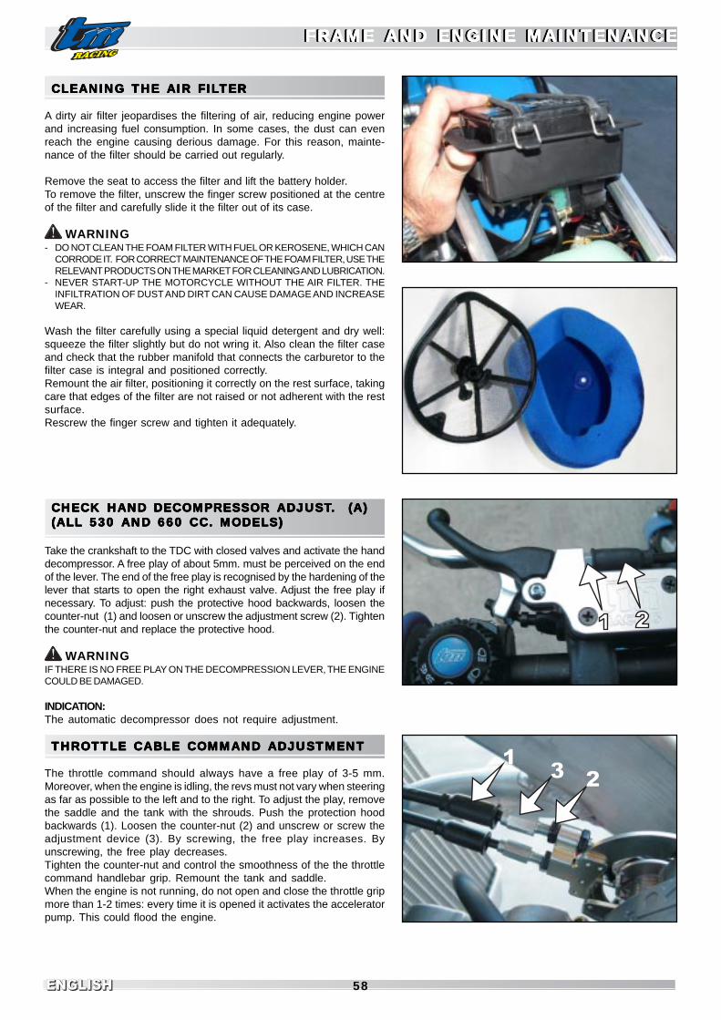
ENGLISHENGLISH 58
13 2
CLEANING CLEANING CLEANING CLEANING CLEANING THE THE THE THE THE AIR FILAIR FILAIR FILAIR FILAIR FILTERTERTERTERTER
A dirty air filter jeopardises the filtering of air, reducing engine powerand increasing fuel consumption. In some cases, the dust can evenreach the engine causing derious damage. For this reason, mainte-nance of the filter should be carried out regularly.
Remove the seat to access the filter and lift the battery holder.To remove the filter, unscrew the finger screw positioned at the centreof the filter and carefully slide it the filter out of its case.
WARNING- DO NOT CLEAN THE FOAM FILTER WITH FUEL OR KEROSENE, WHICH CAN
CORRODE IT. FOR CORRECT MAINTENANCE OF THE FOAM FILTER, USE THERELEVANT PRODUCTS ON THE MARKET FOR CLEANING AND LUBRICATION.
- NEVER START-UP THE MOTORCYCLE WITHOUT THE AIR FILTER. THEINFILTRATION OF DUST AND DIRT CAN CAUSE DAMAGE AND INCREASEWEAR.
Wash the filter carefully using a special liquid detergent and dry well:squeeze the filter slightly but do not wring it. Also clean the filter caseand check that the rubber manifold that connects the carburetor to thefilter case is integral and positioned correctly.Remount the air filter, positioning it correctly on the rest surface, takingcare that edges of the filter are not raised or not adherent with the restsurface.Rescrew the finger screw and tighten it adequately.
CHECK HAND DECOMPRESSOR CHECK HAND DECOMPRESSOR CHECK HAND DECOMPRESSOR CHECK HAND DECOMPRESSOR CHECK HAND DECOMPRESSOR ADJUSTADJUSTADJUSTADJUSTADJUST..... (A) (A) (A) (A) (A)(ALL 530 AND 660 CC. MODELS)(ALL 530 AND 660 CC. MODELS)(ALL 530 AND 660 CC. MODELS)(ALL 530 AND 660 CC. MODELS)(ALL 530 AND 660 CC. MODELS)
Take the crankshaft to the TDC with closed valves and activate the handdecompressor. A free play of about 5mm. must be perceived on the endof the lever. The end of the free play is recognised by the hardening of thelever that starts to open the right exhaust valve. Adjust the free play ifnecessary. To adjust: push the protective hood backwards, loosen thecounter-nut (1) and loosen or unscrew the adjustment screw (2). Tightenthe counter-nut and replace the protective hood.
WARNINGIF THERE IS NO FREE PLAY ON THE DECOMPRESSION LEVER, THE ENGINECOULD BE DAMAGED.
INDICATION:The automatic decompressor does not require adjustment.
THROTTLE CABLE COMMAND ADJUSTMENTTHROTTLE CABLE COMMAND ADJUSTMENTTHROTTLE CABLE COMMAND ADJUSTMENTTHROTTLE CABLE COMMAND ADJUSTMENTTHROTTLE CABLE COMMAND ADJUSTMENT
The throttle command should always have a free play of 3-5 mm.Moreover, when the engine is idling, the revs must not vary when steeringas far as possible to the left and to the right. To adjust the play, removethe saddle and the tank with the shrouds. Push the protection hoodbackwards (1). Loosen the counter-nut (2) and unscrew or screw theadjustment device (3). By screwing, the free play increases. Byunscrewing, the free play decreases.Tighten the counter-nut and control the smoothness of the the throttlecommand handlebar grip. Remount the tank and saddle.When the engine is not running, do not open and close the throttle gripmore than 1-2 times: every time it is opened it activates the acceleratorpump. This could flood the engine.
FRAME AND ENGINE MAINTENANCEFRAME AND ENGINE MAINTENANCEFRAME AND ENGINE MAINTENANCEFRAME AND ENGINE MAINTENANCEFRAME AND ENGINE MAINTENANCEFRAME AND ENGINE MAINTENANCEFRAME AND ENGINE MAINTENANCEFRAME AND ENGINE MAINTENANCEFRAME AND ENGINE MAINTENANCEFRAME AND ENGINE MAINTENANCE

ENGLISHENGLISHENGLISH59
HYDRAULIC CLUTCH AJP PUMPHYDRAULIC CLUTCH AJP PUMPHYDRAULIC CLUTCH AJP PUMPHYDRAULIC CLUTCH AJP PUMPHYDRAULIC CLUTCH AJP PUMP
ADJUSTMENT OF CLUTCH LEVER BASIC POSITIONUse the adjustment screw (4) to adjust the basic position of the clutchlever. In this way the optimal position for the clutch lever can be foundfor any hand size. If the adjustment screw is turned clockwise, theclutch lever approaches the handlebar. If the adjustment screw is turnedanticlockwise, the clutch lever moves away form the handle bar.The adjustment screw (5) is used to adjust the pump run after havingadjusted the position of the lever.
WARNINGTHE RANGE OF ADJUSTMENT IS LIMITED. ONLY TURN THE ADJUSTMENTSCREW MANUALLY WITHOUT FORCE.
CHECK HYDRAULIC CLUTCH FLUID LEVELThe reservoir is part of the clutch pump positioned on the handlebarand has an inspection window: with the reservoir in a horizontal position,the level of the fluid must never fall below the centreline of the window,nor be above the upper margin. If it is necessary to top-up the oil,remove the screws (6) and then the cover (7) together with the rubberseal (8). Keeping the reservoir in a horizontal position,top-up with DOT4brake fluid.
WARNING- FOR THE HYDRAULIC COMMAND OF THE CLUTCH, TM USES DOT4 BRAKE
FLUID, NEVER USE DOT5 OR OTHER.- DO NOT ALLOW BRAKE FLUID TO COME INTO CONTACT WITH PAINTED
PARTS. THE BRAKE FLUID CORRODES THE PAINT !- ONLY USE CLEAN BRAKE FLUID OUT OF HERMETICALLY-SEALED
CONTAINERS.
HYDRAULIC CLUTCH BREMBO PUMPHYDRAULIC CLUTCH BREMBO PUMPHYDRAULIC CLUTCH BREMBO PUMPHYDRAULIC CLUTCH BREMBO PUMPHYDRAULIC CLUTCH BREMBO PUMP
ADJUSTMENT OF CLUTCH LEVER BASIC POSITION
With this option, to adjust the clutch lever distance from the handlebargrip (see maintenance operation), you have to turn the adjustmentknob (1).Rotate clockwise to increase the distance or counterclockwise todecrease the distance.
CHECK HYDRAULIC CLUTCH FLUID LEVELThe reservoir is part of the clutch pump positioned on the handlebar.To check the fluid level remove the screws (2) and the cap (3) togetherwith the rubber seal (4). With the reservoir in a horizontal position, thefluid level must be aligned with the mark visible inside the reservoir. Ifnecessary, top up with brake fluid DOT4.
WARNING- FOR THE HYDRAULIC COMMAND OF THE CLUTCH, TM USES DOT4 BRAKE
FLUID, NEVER USE DOT5 OR OTHER.- DO NOT ALLOW BRAKE FLUID TO COME INTO CONTACT WITH PAINTED
PARTS. THE BRAKE FLUID CORRODES THE PAINT !- ONLY USE CLEAN BRAKE FLUID OUT OF HERMETICALLY-SEALED
CONTAINERS.
FRAME AND ENGINE MAINTENANCEFRAME AND ENGINE MAINTENANCEFRAME AND ENGINE MAINTENANCEFRAME AND ENGINE MAINTENANCEFRAME AND ENGINE MAINTENANCEFRAME AND ENGINE MAINTENANCEFRAME AND ENGINE MAINTENANCEFRAME AND ENGINE MAINTENANCEFRAME AND ENGINE MAINTENANCEFRAME AND ENGINE MAINTENANCE
4 2
3
1
8
7
6
5
4
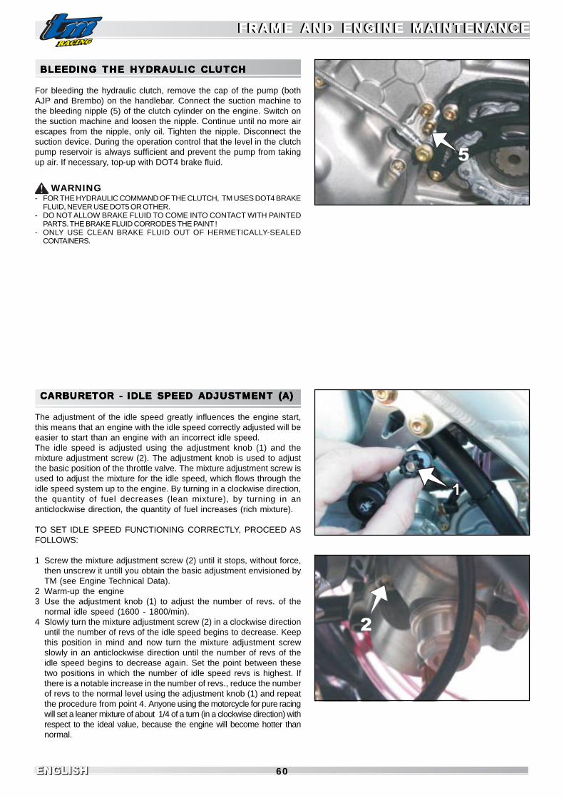
ENGLISHENGLISH 60
5
FRAME AND ENGINE MAINTENANCEFRAME AND ENGINE MAINTENANCEFRAME AND ENGINE MAINTENANCEFRAME AND ENGINE MAINTENANCEFRAME AND ENGINE MAINTENANCEFRAME AND ENGINE MAINTENANCEFRAME AND ENGINE MAINTENANCEFRAME AND ENGINE MAINTENANCEFRAME AND ENGINE MAINTENANCEFRAME AND ENGINE MAINTENANCE
2
BLEEDING THE HYDRAULIC CLUTCHBLEEDING THE HYDRAULIC CLUTCHBLEEDING THE HYDRAULIC CLUTCHBLEEDING THE HYDRAULIC CLUTCHBLEEDING THE HYDRAULIC CLUTCH
For bleeding the hydraulic clutch, remove the cap of the pump (bothAJP and Brembo) on the handlebar. Connect the suction machine tothe bleeding nipple (5) of the clutch cylinder on the engine. Switch onthe suction machine and loosen the nipple. Continue until no more airescapes from the nipple, only oil. Tighten the nipple. Disconnect thesuction device. During the operation control that the level in the clutchpump reservoir is always sufficient and prevent the pump from takingup air. If necessary, top-up with DOT4 brake fluid.
WARNING- FOR THE HYDRAULIC COMMAND OF THE CLUTCH, TM USES DOT4 BRAKE
FLUID, NEVER USE DOT5 OR OTHER.- DO NOT ALLOW BRAKE FLUID TO COME INTO CONTACT WITH PAINTED
PARTS. THE BRAKE FLUID CORRODES THE PAINT !- ONLY USE CLEAN BRAKE FLUID OUT OF HERMETICALLY-SEALED
CONTAINERS.
CARBURETOR - CARBURETOR - CARBURETOR - CARBURETOR - CARBURETOR - IDLE SPEED ADJUSTMENTIDLE SPEED ADJUSTMENTIDLE SPEED ADJUSTMENTIDLE SPEED ADJUSTMENTIDLE SPEED ADJUSTMENT (A) (A) (A) (A) (A)
The adjustment of the idle speed greatly influences the engine start,this means that an engine with the idle speed correctly adjusted will beeasier to start than an engine with an incorrect idle speed.The idle speed is adjusted using the adjustment knob (1) and themixture adjustment screw (2). The adjustment knob is used to adjustthe basic position of the throttle valve. The mixture adjustment screw isused to adjust the mixture for the idle speed, which flows through theidle speed system up to the engine. By turning in a clockwise direction,the quantity of fuel decreases (lean mixture), by turning in ananticlockwise direction, the quantity of fuel increases (rich mixture).
TO SET IDLE SPEED FUNCTIONING CORRECTLY, PROCEED ASFOLLOWS:
1 Screw the mixture adjustment screw (2) until it stops, without force,then unscrew it untill you obtain the basic adjustment envisioned byTM (see Engine Technical Data).
2 Warm-up the engine3 Use the adjustment knob (1) to adjust the number of revs. of the
normal idle speed (1600 - 1800/min).4 Slowly turn the mixture adjustment screw (2) in a clockwise direction
until the number of revs of the idle speed begins to decrease. Keepthis position in mind and now turn the mixture adjustment screwslowly in an anticlockwise direction until the number of revs of theidle speed begins to decrease again. Set the point between thesetwo positions in which the number of idle speed revs is highest. Ifthere is a notable increase in the number of revs., reduce the numberof revs to the normal level using the adjustment knob (1) and repeatthe procedure from point 4. Anyone using the motorcycle for pure racingwill set a leaner mixture of about 1/4 of a turn (in a clockwise direction) withrespect to the ideal value, because the engine will become hotter thannormal.

ENGLISHENGLISHENGLISH61
4
NOTE: If the described methods are followed and satisfying resultsare not obtained, the cause could be a Pilot jet with unsuitabledimensions.a) If the mix adjustment screw is screwed right down without variationof the number of revs of the idle speed, a smaller Pilot jet must beinstalled.b) If the engine switches off with the mix adjustment screw still openby two turns, a larger Pilot jet must be installed. Obviously, after thejet has been replaced, adjustment must be carried out again fromthe beginning.
5 Now, adjust the number of revs. of the idle speed desired using theadjustment knob.
6 In presence of large variations of external temperature and altitude,the idle speed must be set again.
To adjust the idle speed mixture screw, a very short screwdrivermay be required. Notches may be useful on the handgrip.
BBBBBASIC INDICAASIC INDICAASIC INDICAASIC INDICAASIC INDICATIONS REGARDING CARBTIONS REGARDING CARBTIONS REGARDING CARBTIONS REGARDING CARBTIONS REGARDING CARBURETURETURETURETURETORORORORORWEARWEARWEARWEARWEAR
The throttle valve, jet needle, needle jet (when present) and the floatneedle valve are subject to great wear caused by engine vibration. As aconsequence the carburetor may malfunction (e.g. enrichening of themixture). These parts must therefore be controlled after 200 hours.
CHECK FUEL LEVELCHECK FUEL LEVELCHECK FUEL LEVELCHECK FUEL LEVELCHECK FUEL LEVEL(FL(FL(FL(FL(FLOOOOOAAAAAT HEIGHT) (A)T HEIGHT) (A)T HEIGHT) (A)T HEIGHT) (A)T HEIGHT) (A)
Disassemble the carburetor and remove the float bowl. Turn thecarburetor upside-down and keep it inclined so that the float rests onthe needle valve but does not compress the spring with its weight.In this position, use a gauge to measure the distance between theapex of the float body and the float bowl surface on the carburetor body(see image).Refer to the technical data for the correct value for your motorcycle.If necessary, adjust the height by slightly bending the float adjustmentplate (4).If possible, also check the tightness and the state of wear of the needlevalve cone: if in doubt replace the valve and brass seat.Mount the float bowl, mount the carburetor and adjust the idle speed.

ENGLISHENGLISH 62
34
5
6
7
8
10
9
11
EMPTYING EMPTYING EMPTYING EMPTYING EMPTYING THE CARBTHE CARBTHE CARBTHE CARBTHE CARBURETURETURETURETURETOR FLOR FLOR FLOR FLOR FLOOOOOAAAAAT BOT BOT BOT BOT BOWLWLWLWLWL
After washing or driving in wet environments (watercourses, etc.) thecarburetor float bowl should be emptied to remove any water that mayhave entered. Water in the float bowl causes working problems. Carrythis operation out when the engine is cold. Close the fuel tap and placea container underneath the carburetor to collect the fuel coming out.Now open the screw (1) to empty the fuel and water. Re-close thescrew, open the fuel tap and control tightness of the system.
- THE FUEL IS HIGHLY INFLAMMABLE AND TOXIC. HANDLE THE FUELWITH CARE. NEVER CARRY OUT OPERATIONS ON THE FUEL SYSTEMNEAR TO FLAMES OR CIGARETTES.
- ALWAYS ALLOW THE ENGINE TO COOL. USE A CLOTH TO REMOVE ANYOVERFLOWING FUEL. MATERIALS IMPREGNATED WITH FUEL ARE ALSOHIGHLY INFLAMMABLE. IF YOU SWALLOW FUEL OR IT COMES INTOCONTACT WITH THE EYES, CONSULT A DOCTOR IMMEDIATELY.
- DISPOSE OF FUEL ACCORDING TO THE REGULATIONS ENVISIONED INYOUR COUNTRY.
OIL CIRCUITOIL CIRCUITOIL CIRCUITOIL CIRCUITOIL CIRCUIT
The delivery pump (3) sucks the oil through the net filter (4) from thesump. The oil is delivered pressurised through a pipe (5) to the filtercartridge where it is purified from all particles and delivered partly tothe crankshaft and partly to the distribution and gearbox.The oil delivered to the crankshaft enters through a co-axial pipe intothe shaft and finally lubricating the big end bearing (6).The oil delivered to the distribution and gears is made to ascend to thetop of the crankcases and, before entering the cylinder, it divides again.A part is channeled towards the gearbox, of which it lubricates, througha distributor (7), the gear toothing.Another part passes through a spray nozzle towards the small end (8)for lubrication of the piston pin.Finally, another part is channeld along the cylinder and through arelevant hole and arrives at the camshafts bearings and to the contactarea between the cam lobes and valve lifters (9-10).All pressurised oil delivered to the main parts of the engine is returnedby fall and depression to the point in which the drainage pump is found(11) which collects the oil and send it back to the oil sump.Note that the oil sump is separate from the rotating parts of the engine(dry sump) but integrated in the casting of the crankcases.The oil circulation is made only by channels machined inside the engine,without using external hoses.
DANGER
FRAME AND ENGINE MAINTENANCEFRAME AND ENGINE MAINTENANCEFRAME AND ENGINE MAINTENANCEFRAME AND ENGINE MAINTENANCEFRAME AND ENGINE MAINTENANCEFRAME AND ENGINE MAINTENANCEFRAME AND ENGINE MAINTENANCEFRAME AND ENGINE MAINTENANCEFRAME AND ENGINE MAINTENANCEFRAME AND ENGINE MAINTENANCE

ENGLISHENGLISHENGLISH63
CHECK ENGINE OIL LEVELCHECK ENGINE OIL LEVELCHECK ENGINE OIL LEVELCHECK ENGINE OIL LEVELCHECK ENGINE OIL LEVEL
The engine oil level must be checked when the engine is running.Start-up the motorcycle on flat ground and keep it in a vertical position(not on the side stand). The oil window is located on the right side ofthe engine of all the models but the the 660 SMX in which the oilwindow is located on the left side (see picture).Start-up the engine and keep it at a constant speed, a little above theidle speed: the oil level must be visible from 1/2 to 3/4 of the windowpositioned on the right side of the motorcycle. If it is too low or cannotbe seen at all, top-up immediately with engine oil. Use the same typethat has already been introduced into the engine.
WARNINGLOW OIL LEVEL, LOW QUALITY OIL, MAINTENANCE INTERVALS LONGER THANTHOSE ESTABLISHED, CAUSE SERIOUS DAMAGE TO THE ENGINE .
ENGINE OILENGINE OILENGINE OILENGINE OILENGINE OIL
Use only high grade motor oil SAE 10W-50 or 20W-50 which corre-sponds to or exceeds the quality standards of the API SG, JASO MAclasses.Bel-Ray Thumper 20W-50 and EXS 10W-50 are the only approved,used and recommended by TM.
WARNINGLOW OIL LEVEL, LOW QUALITY OIL MAINTENANCE INTERVALS LONGER THANTHOSE ESTABLISHED, CAUSE SERIOUS DAMAGE TO THE ENGINE .
CHANGE ENGINE OIL (A)CHANGE ENGINE OIL (A)CHANGE ENGINE OIL (A)CHANGE ENGINE OIL (A)CHANGE ENGINE OIL (A)
WARNING: WHEN CHANGING THE OIL, CLEAN THE MAGNET OF THE OILDRAIN BOLT AND REPLACE THE FILTER CARTRIDGE.
The oil must be changed with the engine at working temperature.
THE ENGINE AT WORKING TEMPERATURE AND THE OIL INSIDE ARE VERYHOT - PAY ATTENTION, BURNS HAZARD.
Position the motorcycle on a flat surface, loosen and unscrew the cap(1) positioned on the lower face of the engine and allow the oil to flowinto a container.BEWARE OF HOT OIL!Clean the cap and incorporated magnet well.After the oil has flowed out completely, clean the sealing face, remountthe cap together with the seal and tighten at 20 Nm. Replace the sealif it is damaged.
DANGER
FRAME AND ENGINE MAINTENANCEFRAME AND ENGINE MAINTENANCEFRAME AND ENGINE MAINTENANCEFRAME AND ENGINE MAINTENANCEFRAME AND ENGINE MAINTENANCEFRAME AND ENGINE MAINTENANCEFRAME AND ENGINE MAINTENANCEFRAME AND ENGINE MAINTENANCEFRAME AND ENGINE MAINTENANCEFRAME AND ENGINE MAINTENANCE
Uses and recommends
4-Stroke
Bel-Ray Thumper
20W-50
Engine Trans Brake Chassis Filter
www.belray.com
USE ONLY HI OCTANE (98) UNLEADEAD FUEL
Bel-Ray EXS synt.
10W-50

ENGLISHENGLISH 64
REPLACEMENT OF OIL FILTER CARTRIDGE(after having emptied the oil from the engine)The cartridge oil filter is situated on the right side of the motorcycleunderneath the cover(1). Place a container under the engine to collectthe oil that escapes from the filter compartment. Loosen the two screws(2), remove the cover and extract the filter cartridge.
Wait until the oil has drained completely, then clean the sealing surfacesof the transmission cover and filter cover, check the O-Ring and replaceit if necessary.Insert a new filter cartridge, making sure that the open side is towardsthe outside of the engine. The filter must slide into the transmissioncover as far as possible in its seat.
FRAME AND ENGINE MAINTENANCEFRAME AND ENGINE MAINTENANCEFRAME AND ENGINE MAINTENANCEFRAME AND ENGINE MAINTENANCEFRAME AND ENGINE MAINTENANCEFRAME AND ENGINE MAINTENANCEFRAME AND ENGINE MAINTENANCEFRAME AND ENGINE MAINTENANCEFRAME AND ENGINE MAINTENANCEFRAME AND ENGINE MAINTENANCE

ENGLISHENGLISHENGLISH65
Remount the cover, being careful to the O-Ring and to insert the filtercover nose correctly into the hole of the filter cartridge. Greasing the O-Ring with a small amount of grease helps to keep it in its seat whenassembling.Tighten the screws at 10Nm.
REMEMBER THAT THE FILTER CARTRIDGE CANNOT BE CLEANED,IT MUST BE REPLACED AT THE ENVISIONED INTERVALS.
Prepare a measuring beaker with 1.4 (1.0 for 660 SMX) Litres of fullysynthetic engine oil of the established type (see engine data). Unscrewthe oil load cap and fill with about 0.8 Litres.Close the cap temporarily, start-up the engine and allow it to run forabout 5 seconds. DO NOT ALLOW IT TO RUN LONGER TO PREVENTDAMAGE.
Re-open the cap and finish filling with the oil remaining in the measuringbeaker.A total of 1.4 (1.0 for 660 SMX) Litres of oil has been introduced.Tighten the cap at 20Nm.Start the engine and check tightness of the filling and emptying caps,the net filter cap and the filter cartridge cover.Finally, check the engine oil level and correct it if necessary.
FRAME AND ENGINE MAINTENANCEFRAME AND ENGINE MAINTENANCEFRAME AND ENGINE MAINTENANCEFRAME AND ENGINE MAINTENANCEFRAME AND ENGINE MAINTENANCEFRAME AND ENGINE MAINTENANCEFRAME AND ENGINE MAINTENANCEFRAME AND ENGINE MAINTENANCEFRAME AND ENGINE MAINTENANCEFRAME AND ENGINE MAINTENANCE

ENGLISHENGLISH 66
TRTRTRTRTROUBLESHOOOUBLESHOOOUBLESHOOOUBLESHOOOUBLESHOOTINGTINGTINGTINGTINGIf you have the envisioned maintenance operations carried out on your motorcycle, you will have very few problems. If, however, aproblem does occur, please look for it in the following table and try to solve it. Please note that a lot of the operations cannot becarried out without the help of technicians . If in doubt, please contact an authorised TM dealer.
CAUSE SOLUTIONPROBLEM
Incorrect command
Burned fuse
Key not inserted or not turned
Battery flat
Low external temperature
Switch “ON” the emergency shutdown button and where
present, turn the key to enable start-up.
Remove the right side panel and replace the 30 A fuse in the
starter relay
Insert the key and turn it in a clockwise direction
Charge the battery and identify the cause of discharging, contact
a specialised workshop.
Start the engine using the kickstarter pedal.
THE STARTER MOTOR
CANNOT TURN THE
ENGINE
Lack of fuel in the engine Open the fuel tap, fill-up with fuel,
observe the indications for start-up (see “Instructions for use”
chapter)
THE STARTER MOTORTURNS THE ENGINE BUTTHE ENGINE DOES NOT
START(MODELS WITH ELECTRIC
STARTER)
The motorcycle hasn’t been used for a while,
therefore the old fuel has remained in thecarburetor
bowl
Fuel supply interrupted
Engine flooded
Spark plug blackened or wet
Incorrect spark plug electrodes gap
Spark plug cover or spark plug damaged
Engine stop button cable damaged, engine stop
button or emergency shutdown damaged
Oxidised CDI unit, pickup orcoil connectors
Water in the carburetor or clogged jets
The volatile fuel components evaporate easily. If the motorcycle
has not been used for more than 1 week, the old fuel should
be emptied from the carburetor bowl. When the bowl has been
filled with fresh fuel, the engine will start immediately.
Disconnect the fuel hose from the carburetor, place it in a
container and open the fuel tap,
- if fuel escapes, clean the carburetor
- if fuel does not escape, control the tank vent pipe or clean the
fuel tap
Use the “by-pass” command as explained in the “Operating
controls” chapter.
Clean and dry the spark plug or replace it.
Adjust the gap between the electrodes to 0.8 mm
Slide off the spark plug cover, unscrew the spark plug, put the
cover back onto the spark plug and, gripping the cover, keep
the threaded part of the spark plug in contact with the head of
the engine.
Turn the engine with the electric starter or pedal, a spark should
appear between the electrodes of the spark plug
- if the spark plug does not produce a spark, it must be replaced
- if there is still no spark, remove the spark plug cover from the
H.T. cable coming from the coil, hold it at a distance of about 5
mm from the head and operate the starting system
- if there is a spark, replace the spark plug cover
- if there is still no spark, check the ignition system
- Replace the spark plug
Remove the saddle and fuel tank, disconnect the emergency
shutdown button cable or the engine stop button cable and
check the spark. If there is a spark, look for the fault along the
emergency shutdown button cable or the engine stop cable.
Remove the saddle, the left side panel and the fuel tank, clean
the connectors and treat them with a contact spray.
Disassemble and clean the carburetor
THE ENGINE DOES NOT
START
(MODELS WITH
KICKSTARTER PEDAL)
TRTRTRTRTROUBLESHOOOUBLESHOOOUBLESHOOOUBLESHOOOUBLESHOOTINGTINGTINGTINGTING
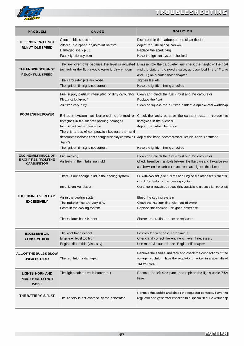
ENGLISHENGLISHENGLISH67
TROUBLESHOOTINGTROUBLESHOOTINGTROUBLESHOOTINGTROUBLESHOOTINGTROUBLESHOOTING
EXCESSIVE OIL
CONSUMPTION
CAUSE SOLUTIONPROBLEM
THE ENGINE WILL NOT
RUN AT IDLE SPEED
Clogged idle speed jet
Altered idle speed adjustment screws
Damaged spark plug
Faulty Ignition system
Disassemble the carburetor and clean the jet
Adjust the idle speed screws
Replace the spark plug
Have the ignition system checked
THE ENGINE DOES NOT
REACH FULL SPEED
The fuel overflows because the level is adjusted
too high or the float needle valve is dirty or worn
The carburetor jets are loose
The ignition timing is not correct
Disassemble the carburetor and check the height of the float
and the state of the needle valve, as described in the “Frame
and Engine Maintenance” chapter
Tighten the jets
Have the ignition timing checked
POOR ENGINE POWER
Fuel supply partially interrupted or dirty carburetor
Float not leakproof
Air filter very dirty
Exhaust system not leakproof, deformed or
fibreglass in the silencer packing damaged
Insufficient valve clearance
There is a loss of compression because the hand
decompressor hasn’t got enough free play (it remains
“tight”)
The ignition timing is not correct
Clean and check the fuel circuit and the carburetor
Replace the float
Clean or replace the air filter, contact a specialised workshop
Check the faulty parts on the exhaust system, replace the
fibreglass in the silencer
Adjust the valve clearance
Adjust the hand decompressor flexible cable command
Have the ignition timing checked
Fuel missing
Air leaks in the intake manifold
Clean and check the fuel circuit and the carburetor
Check the rubber manifolds between the filter case and the carburetor
and between the carburetor and head and tighten the clamps
THE ENGINE OVERHEATS
EXCESSIVELY
There is not enough fluid in the cooling system
Insufficient ventilation
Air in the cooling system
The radiator fins are very dirty
Foam in the cooling system
The radiator hose is bent
Fill with coolant (see “Frame and Engine Maintenance”) chapter,
check for leaks of the cooling system
Continue at sustained speed (it is possible to mount a fan optional)
Bleed the cooling system
Clean the radiator fins with jets of water
Replace the coolant, use good antifreeze
Shorten the radiator hose or replace it
The vent hose is bent
Engine oil level too high
Engine oil too thin (viscosity)
Position the vent hose or replace it
Check and correct the engine oil level if necessary
Use more viscous oil, see “Engine oil” chapter
ALL OF THE BULBS BLOW
UNEXPECTEDLY The regulator is damaged
Remove the saddle and tank and check the connections of the
voltage regulator. Have the regulator checked in a specialised
TM workshop
LIGHTS, HORN AND
INDICATORS DO NOT
WORK
The lights cable fuse is burned out Remove the left side panel and replace the lights cable 7.5A
fuse
THE BATTERY IS FLATThe battery is not charged by the generator
Remove the saddle and check the regulator contacts. Have the
regulator and generator checked in a specialised TM workshop
TROUBLESHOOTINGTROUBLESHOOTINGTROUBLESHOOTINGTROUBLESHOOTINGTROUBLESHOOTING
ENGINE MISFIRINGS ORBACKFIRES FROM THE
CARBURETOR

ENGLISHENGLISH 68
STSTSTSTSTORAORAORAORAORAGEGEGEGEGE
CLEANINGCLEANINGCLEANINGCLEANINGCLEANINGClean the motorcycle regularly in a way to maintain the surface of the plastic parts in good condition.To do this, it is advised to use hot water with a detergent and sponge. Most of the dirt can be removed using weak water jets.
WARNINGNEVER CLEAN THE MOTORCYCLE WITH HIGH PRESSURE CLEANING DEVICES OR WITH STRONG JETS OF WATER! BECAUSE OF THE HIGHPRESSURE THE WATER COULD REACH THE ELECTRICAL PARTS, CONNECTORS, FLEXIBLE CABLE COMMANDS, BEARINGS, THE CARBURETORETC... AND CAUSE FAULTS OR PREMATURE BREAKAGE OF THESE PARTS.
- Before washing, close the exhaust pipe rear end to prevent water from entering.- Normal soaps, found on the market, should be used to clean the motorcycle. Particularly dirty parts should be cleaned using a
brush.- After having rinsed the motorcycle well, using a weak jet of water, dry using compressed air and a cloth. Empty the carburetor
bowl. Immediately after, make a brief journey until the engine has reached the normal working temperature and at this pointactivate the brakes. Because of the heat, the water that is left in the unreachable points and on the brakes will evaporate.
- After the motorcycle has cooled down, oil and grease all motion parts and bearings. Treat the chain with an appropriate spray.Also oil the fuel tap.
- To prevent faults in the electric system, treat the emergency shutdown button, the engine stop button, the light switch and theconnectors with contact spray.
PRECAPRECAPRECAPRECAPRECAUTION FOR UTION FOR UTION FOR UTION FOR UTION FOR WINTER USEWINTER USEWINTER USEWINTER USEWINTER USE
DANGER
If the motorcycle is not to be used for a long time, take the following measures:- Clean the motorcycle well (see CLEANING chapter)- Change the engine oil and oil filter cartridge, clean the net filter (old oil contains dangerous impurities).- Check the antifreeze and the quantity of the coolant.- Warm the engine up again, close the fuel tap and wait until the engine stops.
Successively open the carburetor bowl empty screw to empty the remaining fuel.- Disassemble the spark plug and pour into the plug hole 5 cc of oil. Activate the kickstart pedal 10 times to distribute the engine
oil onto the walls of the cylinder and then remount the spark plug.- Bring the piston in compression to induce valve closure- Empty the fuel tank, collecting the fuel in an appropriate container.- Adjust tyre pressure.- Grease bearings or command lever supports, footrests, etc. and also the chain. Disassemble the battery and charge it (see
BATTERY chapter). Store it disassembled from the motorcycle.- The place of storage should be dry and not subject to large temperature changes.- Cover the motorcycle with a sheet or cover that allows air to pass. Do not use materials that do not allow the passage of air, as
humidity would not be able to escape and could cause oxidation.
WARNINGIT IS NOT ADVISED TO START THE ENGINE FOR SHORT TIMES. THE ENGINE WOULD NOT HEAT UP SUFFICIENTLY, AND THEREFORE THE STEAMCREATED DURING THE COMBUSTION PROCESS WOULD CONDENSE CAUSING THE OXIDATION OF THE EXHAUST VALVES.
START-UP AFTER SEASONAL PAUSE- Mount the charged battery (pay attention to polarity)- Fill the tank with new fuel- Control the motorcycle as before any start-up (see “Instructions for use” chapter) - Make a short inspection trip.
WARNING: Before storing the motorcycle for the season, check functioning and wear of all components. If maintenance operations,repairs or modifications are necessary, it is a good idea to have them carried out during the winter time (less busy workshops). Inthis way it is possible to avoid long waits in the workshop at the beginning of the spring season.
CLEANINGCLEANINGCLEANINGCLEANINGCLEANING
PRECAPRECAPRECAPRECAPRECAUTION FOR UTION FOR UTION FOR UTION FOR UTION FOR WINTER USEWINTER USEWINTER USEWINTER USEWINTER USE
STSTSTSTSTORAORAORAORAORAGEGEGEGEGE
If the motorcycle is also used in winter it is necessary to consider the salt on the roads and appropriate countermeasures must betaken against the salt aggressiveness.- The motorcycle must be cleaned well after use and left to dry.- Treat engine, carburetor, swing arm and all other bright or galvanised components (except brake disc) with wax-based anti-
corrosives.
PREVENT CONTACT OF THE ANTICORROSIVE WITH BRAKE DISCS. THIS CAUSES GREAT REDUCTION IN THE BRAKING EFFECT.
WARNINGAFTER TRAVELLING ON ROADS WHERE SALT HAS BEEN SPREAD, WASH THE MOTORCYCLE WELL WITH COLD WATER AND LEAVE IT TO DRY.

ENGLISHENGLISHENGLISH69
TECHNICAL DTECHNICAL DTECHNICAL DTECHNICAL DTECHNICAL DAAAAATTTTTA - ENGINEA - ENGINEA - ENGINEA - ENGINEA - ENGINE
LEGEND: E.S. = Electric start K.S. = Kick start
450450450450450SMM/SMRSMM/SMRSMM/SMRSMM/SMRSMM/SMR
TECHNICAL DTECHNICAL DTECHNICAL DTECHNICAL DTECHNICAL DAAAAATTTTTA - ENGINE 250 END/MX/SMX/SMR/SMM - 450 END/MX/SMX/SMR/SMM 200A - ENGINE 250 END/MX/SMX/SMR/SMM - 450 END/MX/SMX/SMR/SMM 200A - ENGINE 250 END/MX/SMX/SMR/SMM - 450 END/MX/SMX/SMR/SMM 200A - ENGINE 250 END/MX/SMX/SMR/SMM - 450 END/MX/SMX/SMR/SMM 200A - ENGINE 250 END/MX/SMX/SMR/SMM - 450 END/MX/SMX/SMR/SMM 20099999450450450450450SMXSMXSMXSMXSMX
450450450450450MXMXMXMXMX
450450450450450ENDENDENDENDEND
250250250250250SMM/SMRSMM/SMRSMM/SMRSMM/SMRSMM/SMR
250250250250250MX/SMXMX/SMXMX/SMXMX/SMXMX/SMX
250250250250250ENDENDENDENDENDENGINEENGINEENGINEENGINEENGINE
4 stroke single-cylinder DOHC , liquid cooled
250 cm3 449 cm3
77x53.6 mm 95x63.4 mm
13.5 : 1 11.5 : 1 12.2 : 1 12.2 : 1 11.5 : 1
unleaded fuel with min. 95 RON
DOHC 4 valves driven by silent chain
A2 / N2 N2 / N3 N1/S1 SM4 / S4 N2 / N3
30 mm 30 mm Ti 30 mm 36 mm 36 mm Ti 36 mm
24.5 mm 24.5 mmTi 24.5 mm 31 mm 31 mm Ti 31 mm
mm. 0.20 mm. 0.20 mm. 0.20 mm. 0.25 mm. 0.20
mm. 0.25 mm. 0.25 mm. 0.25 mm. 0.25 mm. 0.25
2 ball bearings
silver-plated needle cage
coppering
forged light alloy
2 rings + 1 oil scraper 1 ring+1 oil scraper 2rings+1scraper
double oil pump ( delivery+ drainage)
fully synthetic premium quality oil SAE 10W-50 API SG-SH
1.4 litres
18 / 67 20 / 57 19 / 57 20 / 57 20 / 57
multiple discs in oil bath
5 speed 5 speed 5 speed 5 speed 5 speed 5 speed
1st 14:28 1st 15:27 1st 14:28 1st14:28 1st 16:27 1st 14:28
2nd 17:25 2nd 17:25 2nd 17:25 2nd 17:25 2nd 17:24 2nd17:25
3rd 19:23 3rd 19:23 3rd 19:23 3rd 19:23 3rd 16:19 3rd 19:23
4th 21:21 4th 21:21 4th 21:21 4th 21:21 4th 21:21 4th 21:21
5th 24:19 5th 23:20 5th 23:20 5th 24:19 5th 23:20 5th 23:20
Kokusan digital CDI with variable timing
12V 180W ----- 12 V 180W 12V 180W ----- 12V 180W
12V180W 12V180W
NGK CR 8E
0.8 mm
liquid cooled 40 % antifreeze, 60 % water(up to -25°C),
forced circulation with pump
1 litre 1.3 litres 1 litre
E.S.+K.S. K.S. E.S.+K.S. E.S.+K.S. K.S. E.S.+K.S.
(E.S.opt.) (E.S.opt.)
Type
Displacement
Cylinder bore and stroke
Compression
Fuel
Distribution
I / E camshafts
Inlet valve diameter
Exhaust valve diameter
Inlet valve cold clearance
Exhaust valve cold clearance
Crankshaft supports
Conrod bearing
Small end plating
Piston
Rings
Lubrication
Engine oil
Oil capacity
Primary transmission straight teeth gears
Clutch
Gearbox (with front engagement)
Gear ratios
Ignition
Generator
Generator with E.S. optional
Spark plug
Electrode gap
Cooling
Coolant fluid capacity
Start-up
TECHNICAL DTECHNICAL DTECHNICAL DTECHNICAL DTECHNICAL DAAAAATTTTTA - ENGINEA - ENGINEA - ENGINEA - ENGINEA - ENGINETECHNICAL DTECHNICAL DTECHNICAL DTECHNICAL DTECHNICAL DAAAAATTTTTA - ENGINE 250 END/MX/SMX/SMR/SMM - 450 END/MX/SMX/SMR/SMM 200A - ENGINE 250 END/MX/SMX/SMR/SMM - 450 END/MX/SMX/SMR/SMM 200A - ENGINE 250 END/MX/SMX/SMR/SMM - 450 END/MX/SMX/SMR/SMM 200A - ENGINE 250 END/MX/SMX/SMR/SMM - 450 END/MX/SMX/SMR/SMM 200A - ENGINE 250 END/MX/SMX/SMR/SMM - 450 END/MX/SMX/SMR/SMM 20099999
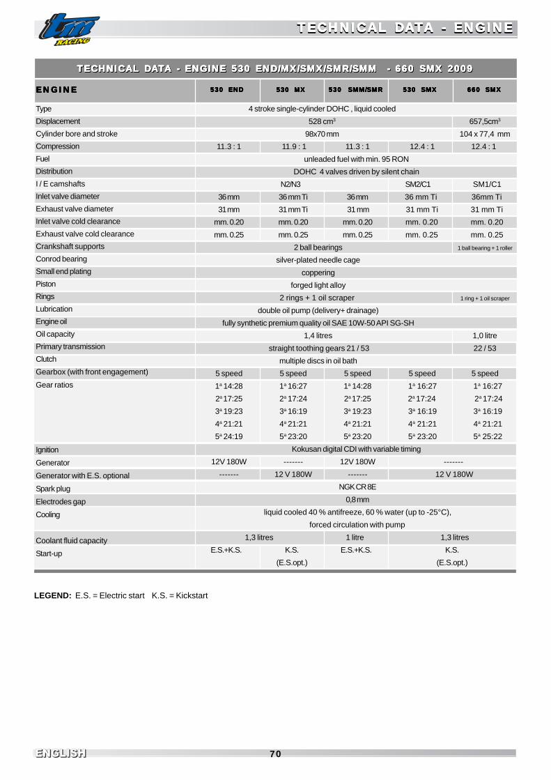
ENGLISHENGLISH 70
TECHNICAL DTECHNICAL DTECHNICAL DTECHNICAL DTECHNICAL DAAAAATTTTTA - ENGINEA - ENGINEA - ENGINEA - ENGINEA - ENGINE
LEGEND: E.S. = Electric start K.S. = Kickstart
TECHNICAL DTECHNICAL DTECHNICAL DTECHNICAL DTECHNICAL DAAAAATTTTTA - ENGINEA - ENGINEA - ENGINEA - ENGINEA - ENGINE
530 SMM/SMR530 SMM/SMR530 SMM/SMR530 SMM/SMR530 SMM/SMR
TECHNICAL DTECHNICAL DTECHNICAL DTECHNICAL DTECHNICAL DAAAAATTTTTA - ENGINE 530 END/MX/SMX/SMR/SMM - 660 SMX 2009A - ENGINE 530 END/MX/SMX/SMR/SMM - 660 SMX 2009A - ENGINE 530 END/MX/SMX/SMR/SMM - 660 SMX 2009A - ENGINE 530 END/MX/SMX/SMR/SMM - 660 SMX 2009A - ENGINE 530 END/MX/SMX/SMR/SMM - 660 SMX 2009TECHNICAL DTECHNICAL DTECHNICAL DTECHNICAL DTECHNICAL DAAAAATTTTTA - ENGINE 530 END/MX/SMX/SMR/SMM - 660 SMX 2009A - ENGINE 530 END/MX/SMX/SMR/SMM - 660 SMX 2009A - ENGINE 530 END/MX/SMX/SMR/SMM - 660 SMX 2009A - ENGINE 530 END/MX/SMX/SMR/SMM - 660 SMX 2009A - ENGINE 530 END/MX/SMX/SMR/SMM - 660 SMX 2009
530 SMX530 SMX530 SMX530 SMX530 SMX530 MX530 MX530 MX530 MX530 MXENGINEENGINEENGINEENGINEENGINE 660 SMX660 SMX660 SMX660 SMX660 SMX530 END530 END530 END530 END530 END
Type
Displacement
Cylinder bore and stroke
Compression
Fuel
Distribution
I / E camshafts
Inlet valve diameter
Exhaust valve diameter
Inlet valve cold clearance
Exhaust valve cold clearance
Crankshaft supports
Conrod bearing
Small end plating
Piston
Rings
Lubrication
Engine oil
Oil capacity
Primary transmission
Clutch
Gearbox (with front engagement)
Gear ratios
Ignition
Generator
Generator with E.S. optional
Spark plug
Electrodes gap
Cooling
Coolant fluid capacity
Start-up
4 stroke single-cylinder DOHC , liquid cooled
528 cm3 657,5cm3
98x70 mm 104 x 77,4 mm
11.3 : 1 11.9 : 1 11.3 : 1 12.4 : 1 12.4 : 1
unleaded fuel with min. 95 RON
DOHC 4 valves driven by silent chain
N2/N3 SM2/C1 SM1/C1
36 mm 36 mm Ti 36 mm 36 mm Ti 36mm Ti
31 mm 31 mm Ti 31 mm 31 mm Ti 31 mm Ti
mm. 0.20 mm. 0.20 mm. 0.20 mm. 0.20 mm. 0.20
mm. 0.25 mm. 0.25 mm. 0.25 mm. 0.25 mm. 0.25
2 ball bearings 1 ball bearing + 1 roller
silver-plated needle cage
coppering
forged light alloy
2 rings + 1 oil scraper 1 ring + 1 oil scraper
double oil pump (delivery+ drainage)
fully synthetic premium quality oil SAE 10W-50 API SG-SH
1,4 litres 1,0 litre
straight toothing gears 21 / 53 22 / 53
multiple discs in oil bath
5 speed 5 speed 5 speed 5 speed 5 speed
1a 14:28 1a 16:27 1a 14:28 1a 16:27 1a 16:27
2a 17:25 2a 17:24 2a 17:25 2a 17:24 2a 17:24
3a 19:23 3a 16:19 3a 19:23 3a 16:19 3a 16:19
4a 21:21 4a 21:21 4a 21:21 4a 21:21 4a 21:21
5a 24:19 5a 23:20 5a 23:20 5a 23:20 5a 25:22
Kokusan digital CDI with variable timing
12V 180W ------- 12V 180W -------
------- 12 V 180W ------- 12 V 180W
NGK CR 8E
0,8 mm
liquid cooled 40 % antifreeze, 60 % water (up to -25°C),
forced circulation with pump
1,3 litres 1 litre 1,3 litres
E.S.+K.S. K.S. E.S.+K.S. K.S.
(E.S.opt.) (E.S.opt.)

ENGLISHENGLISHENGLISH71
CARBCARBCARBCARBCARBURETURETURETURETURETOR SETTINGSOR SETTINGSOR SETTINGSOR SETTINGSOR SETTINGSCARBCARBCARBCARBCARBURETURETURETURETURETOR SETTINGSOR SETTINGSOR SETTINGSOR SETTINGSOR SETTINGS
NNNNN.B
:.B
:.B
:.B
:.B
: IN
FO
RM
A I
NF
OR
MA
IN
FO
RM
A I
NF
OR
MA
IN
FO
RM
AT
ION
S C
HA
NG
ED
FR
TIO
NS
CH
AN
GE
D F
RT
ION
S C
HA
NG
ED
FR
TIO
NS
CH
AN
GE
D F
RT
ION
S C
HA
NG
ED
FR
OM
O
M
OM
O
M
OM
TH
E P
RE
VIO
US
RE
LE
AS
E
TH
E P
RE
VIO
US
RE
LE
AS
E
TH
E P
RE
VIO
US
RE
LE
AS
E
TH
E P
RE
VIO
US
RE
LE
AS
E
TH
E P
RE
VIO
US
RE
LE
AS
E A
RE
IN
BO
LD
A
RE
IN
BO
LD
A
RE
IN
BO
LD
A
RE
IN
BO
LD
A
RE
IN
BO
LD
TY
PE
ST
YP
ES
TY
PE
ST
YP
ES
TY
PE
S
KE
IHIN
KE
IHIN
KE
IHIN
KE
IHIN
KE
IHIN
Type
Mai
n Je
t
Slo
w J
et
Jet N
eedl
e
Clip
pos
ition
Thr
ottle
val
ve
Slo
w a
ir sc
rew
Flo
at h
eigh
t
Fue
l val
ve
Acc
eler
ator
pum
p op
enin
g
Acc
eler
ator
pum
p cl
osin
g
FCR
D39
165
50
NC
YP
3rd fr
om to
p
1,5
1.25
turn
s
7.0
mm
3,8
0% th
rottle
stro
ke
100%
thro
ttle s
troke
FCR
D39
180
45
NC
YP
3rd fr
om to
p
1,5
1.25
turn
s
7.0
mm
3,8
0% th
rottle
stro
ke
100%
thro
ttle s
troke
11/0
925
0cc.
MX
12/0
925
0cc.
SM
X
FCR
D39
165
45
OC
EM
P
3rd fr
om
to
p
1,5
1.5
turn
s
7.0
mm
3,8
0% th
rottl
e stro
ke
80%
thro
ttle st
roke
13/0
845
0cc.
EN
D14
/09
450c
c.M
X53
0cc.
MX
15/0
945
0cc.
SM
X53
0cc.
SM
X
16/0
966
0cc.
SM
X17
/08
18/0
820
/08
FCR
D39
165
50
OC
EMP
3rd fr
om to
p
1,5
1.5
turn
s
7.0
mm
3,8
0% th
rottl
e st
roke
80%
thro
ttle s
troke
FCR
D41
190
45
OC
EMP
3rd fr
om to
p
1,5
1.0
turn
s
7.0
mm
3,8
0% th
rottle
stro
ke
100%
thro
ttle s
troke
19/0
8
FCR
D41
190
45
NC
YP
3rd fr
om to
p
1,5
1.0
turn
s
7.0
mm
3,8
0% th
rottle
stro
ke
100%
thro
ttle s
troke
TM
RA
TM
RA
TM
RA
TM
RA
TM
RA
CIN
G 4
T C
AR
BC
ING
4T
CA
RB
CIN
G 4
T C
AR
BC
ING
4T
CA
RB
CIN
G 4
T C
AR
BU
RE
TU
RE
TU
RE
TU
RE
TU
RE
TO
RS
SE
TT
ING
O
RS
SE
TT
ING
O
RS
SE
TT
ING
O
RS
SE
TT
ING
O
RS
SE
TT
ING
TTTT TA
BLE
4T
2
009
MO
DE
LS
0
3/11
/08
R
EV
AB
LE 4
T
200
9 M
OD
ELS
03/
11/0
8
RE
VA
BLE
4T
2
009
MO
DE
LS
0
3/11
/08
R
EV
AB
LE 4
T
200
9 M
OD
ELS
03/
11/0
8
RE
VA
BLE
4T
2
009
MO
DE
LS
0
3/11
/08
R
EV .... .
02
02
02
02
02
TM
RA
TM
RA
TM
RA
TM
RA
TM
RA
CIN
G 4
T C
AR
BC
ING
4T
CA
RB
CIN
G 4
T C
AR
BC
ING
4T
CA
RB
CIN
G 4
T C
AR
BU
RE
TU
RE
TU
RE
TU
RE
TU
RE
TO
RS
SE
TT
ING
O
RS
SE
TT
ING
O
RS
SE
TT
ING
O
RS
SE
TT
ING
O
RS
SE
TT
ING
TTTT TA
BLE
4T
2
009
MO
DE
LS
0
3/11
/08
R
EV
AB
LE 4
T
200
9 M
OD
ELS
03/
11/0
8
RE
VA
BLE
4T
2
009
MO
DE
LS
0
3/11
/08
R
EV
AB
LE 4
T
200
9 M
OD
ELS
03/
11/0
8
RE
VA
BLE
4T
2
009
MO
DE
LS
0
3/11
/08
R
EV .... .
02
02
02
02
02
MIK
UN
IM
IKU
NI
MIK
UN
IM
IKU
NI
MIK
UN
I
Type
Mai
n Je
t
Slo
w J
et
Nee
dle
Jet
Jet N
eedl
e
Clip
pos
ition
Thr
ottle
val
ve
Slo
w a
ir S
crew
Slo
w a
ir A
ir Je
t
Flo
at h
eigh
t
Fue
l val
ve
Acc
. Pum
p R
od L
engt
h
Sto
pper
Scr
ew O
uts.
Len
gth
Acc
eler
ator
Pum
p Je
t
TDM
R 3
8
170
45 P-6
10E
1-52
3rd fr
om to
p
2.0
no h
oles
1.5
turn
120
11.0
mm
.
3.8
81.0
mm
.
13.0
mm
.
35
TDM
R 4
1
170
50 P-6
10E
1-52
3rd fr
om to
p
2.0
no h
oles
1.0
turn
120
11.0
mm
.
3.8
85.0
mm
.
11.5
mm
.
40
01/0
825
0cc.
EN
D/S
MM
/SM
R
02/0
845
0cc.
SM
R7S
MM
530c
c.E
ND
/SM
M/
SM
R
03/0
804
/08
07/0
808
/08
09/0
805
/08
06/0
810
/08

ENGLISHENGLISH 72
ENGINE OIL
Only use premium quality fully synthetic oils SAE10W-50 that correspondto or exceed the quality standards of the API - SG or SH classes(indication on container).
WARNINGA LEVEL THAT IS TOO LOW, LOW QUALITY OIL OR MAINTENANCE INTERVALSLONGER THAN ESTABLISHED, CAUSE SERIOUS DAMAGE TO THE ENGINE.
ENGINE TIGHTENING TORQUESENGINE TIGHTENING TORQUESENGINE TIGHTENING TORQUESENGINE TIGHTENING TORQUESENGINE TIGHTENING TORQUES
Crankase Allen screws, transmission cover, clutch cover, ignition cover
Oil drain screw cap
Oil filler screw cap
Oil net filter screw cap
Oil cartridge filter cover Allen screws
Engine oil pump body screws
Head-cylinder nuts
Head-cylinder flanged nuts
Head-cylinder flanged nuts
Head-cylinder fastenening screws
Camshaft bearing cap Allen screw
Camshaft cap Allen screws
Distribution chain tensioner Allen screws
Water pump cover Allen screws
Water pump rotor
Head cover Allen screws
Primary transmission pinion nut
Clutch hub nut
Clutch springs Allen screws
Starter motor bush csk head Allen screw
Starter motor fastening Allen screws
Mobile chain guide fastening flanged screws
Ignition stator Allen screws
Ignition pickup fastening Allen screws
Allen screws for gear drum lock lever
Ignition flywheel flanged nut
Kickstart pedal screw
Gear pedal Allen screw
Exhaust manifold flanged nuts
General screws/nuts
General screws/nuts
General screws/nuts
10 Nm
20 Nm
20 Nm
15 Nm
10 Nm
10 Nm
45 Nm
20 Nm
12 Nm
20 Nm
12 Nm
12 Nm
10 Nm
10 Nm
Loctite 243 + 15 Nm
10 Nm
Loctite 270 + 100 Nm
Loctite 270 + 80 Nm
8 Nm
Loctite 243 + 6 Nm
12 Nm
12 Nm
Loctite 243 + 8 Nm
8 Nm
Loctite 243 + 10 Nm
60 Nm
Loctite 243 + 25 Nm
Loctite 243 + 10 Nm
Loctite 243 + 12 Nm
8 Nm
10 Nm
20 Nm
M6
M16x1.5
M20x1.5
M28x1.5
M6
M6
M10
M8
M6
M8
M6
M6
M6
M6
M8
M6
M20x1.25
M18x1.5
M6
M5
M6
M6
M5
M5
M6
M12x1
M8
M6
M6
M5
M6
M8
ENGINE ENGINE ENGINE ENGINE ENGINE TIGHTENING TIGHTENING TIGHTENING TIGHTENING TIGHTENING TTTTTORORORORORQQQQQUESUESUESUESUESENGINE ENGINE ENGINE ENGINE ENGINE TIGHTENING TIGHTENING TIGHTENING TIGHTENING TIGHTENING TTTTTORORORORORQQQQQUESUESUESUESUES

ENGLISHENGLISHENGLISH73
TECHNICAL DTECHNICAL DTECHNICAL DTECHNICAL DTECHNICAL DAAAAATTTTTA - CYA - CYA - CYA - CYA - CYCLE PCLE PCLE PCLE PCLE PARARARARARTTTTTTECHNICAL DTECHNICAL DTECHNICAL DTECHNICAL DTECHNICAL DAAAAATTTTTA - CYA - CYA - CYA - CYA - CYCLE PCLE PCLE PCLE PCLE PARARARARART 250/450/530 END - 250/450/530 MX 2009T 250/450/530 END - 250/450/530 MX 2009T 250/450/530 END - 250/450/530 MX 2009T 250/450/530 END - 250/450/530 MX 2009T 250/450/530 END - 250/450/530 MX 2009
Frame
Front suspension
Rear/front suspension travel
Rear suspension
Front disc brake
Rear disc brake
Brake disc wear limit
Front tyre
Off-road air pressure
Rear tyre
Off-road air pressure
Tank capacity
Final transmission
Chain
Optional rear sprockets
Bulbs (only END)
Battery
Twin-spar high resistance aluminium alloy frame
Marzocchi USD fork / Paioli USD fork / Ohlins USD fork
300/315 mm
Aluminium swing arm, Progressive mechanical linkage, Sachs rear shock (optional Ohlins)
Ø 270 mm floating caliper
Ø 245 mm floating caliper
mm. 0.4 below original thickness
90/90 - 21”
1.1 bar
120/90 - 18” 140/80 - 18” 100/90 - 19” 110/90 - 19”
1.1 bar
9 litres
13/51 13/50 13/50 13/51 14/51 14/51
O-Ring 5/8 x 1/4” 5/8 x 1/4”
48, 49, 50, 51, 52, 53
Headlight/full beam S212V 45/40W BA20d / HS112V 35/35W (Opt.Cyclops H3 12V 55W PK22s)
Front position light T4W 12V 4W BA9s / W5W12V 5W (Opt. Cyclops T10 12V 5W)
Position/stop/number plate light P21/5W 12V 21/5W BAY15d / LED 12V 0.9W / 0.06W
Indicator R10W 12V 10W BA15S
12V 6Ah 12V 6Ah (only with E.S. opt.)
530 MX530 MX530 MX530 MX530 MX250 END250 END250 END250 END250 END 450 END450 END450 END450 END450 END 530 END530 END530 END530 END530 END 250 MX250 MX250 MX250 MX250 MX 450 MX450 MX450 MX450 MX450 MX
TIGHTENING TORQUES 250/450/530 END - 250/450/530 MXTIGHTENING TORQUES 250/450/530 END - 250/450/530 MXTIGHTENING TORQUES 250/450/530 END - 250/450/530 MXTIGHTENING TORQUES 250/450/530 END - 250/450/530 MXTIGHTENING TORQUES 250/450/530 END - 250/450/530 MX
Front wheel axle flanged nut
Front brake caliper fastening screws (END,MX)
Front brake disc fastening screws
Rear brake disc fastening screws
Upper fork head fastening screws
Lower fork head fastening screws
Paioli fork leg fastening screws
Ohlins fork leg fastening screws
Rear wheel axle flanged nut
Swing arm axle flanged nut
Handlebar caps fastening screws
Handlebar elastic support nut
Upper end shock nut
Lower end shock nut
Rear sprocket nuts
Rear brake pedal adjustment nut
Engine fastening screws
General frame screws
General frame nuts
M20x1.5
M8
M6 cl. 10.9
M6 cl. 10.9
M8
M8
M6
M8
M22x1.5
M16x1.5
M8
M10
M10x1.25
M10x1.25
M8
M6
M10
M6
M8
M10
M6
M8
M10
40 Nm
25 Nm
15 Nm
15 Nm
20 Nm
20 Nm
12 Nm
12 Nm
80 Nm
80 Nm
20 Nm
35 Nm
40 Nm
35 Nm
35 Nm
15 Nm
45 Nm
10 Nm
25 Nm
45 Nm
15 Nm
30 Nm
50 Nm
TECHNICAL DTECHNICAL DTECHNICAL DTECHNICAL DTECHNICAL DAAAAATTTTTA - CYA - CYA - CYA - CYA - CYCLE PCLE PCLE PCLE PCLE PARARARARARTTTTTTECHNICAL DTECHNICAL DTECHNICAL DTECHNICAL DTECHNICAL DAAAAATTTTTA - CYA - CYA - CYA - CYA - CYCLE PCLE PCLE PCLE PCLE PARARARARART 250/450/530 END - 250/450/530 MX 2009T 250/450/530 END - 250/450/530 MX 2009T 250/450/530 END - 250/450/530 MX 2009T 250/450/530 END - 250/450/530 MX 2009T 250/450/530 END - 250/450/530 MX 2009

ENGLISHENGLISH 74
TIGHTENING TORQUES 250/450/530 SMR/SMM - 250/450/530/660 SMXTIGHTENING TORQUES 250/450/530 SMR/SMM - 250/450/530/660 SMXTIGHTENING TORQUES 250/450/530 SMR/SMM - 250/450/530/660 SMXTIGHTENING TORQUES 250/450/530 SMR/SMM - 250/450/530/660 SMXTIGHTENING TORQUES 250/450/530 SMR/SMM - 250/450/530/660 SMX
Front wheel axle flanged nut
Front brake caliper fastening screws (SMR,SMM,SMX)
Rear brake caliper fastening screws (SMM)
Front brake disc fastening screws
Rear brake disc fastening screws(SMR,SMX)
Rear brake disc fastening nut (SMM)
Upper fork head fastening screws
Lower fork head fastening screws
Paioli fork leg fastening screws
Ohlins fork leg fastening screws
Rear wheel axle flanged nut
Swing arm axle flanged nut
Handlebar caps fastening screws
Handlebar elastic support nut
Upper end shock nut
Lower end shock screws
Rear sprocket nuts
Rear brake pedal adjustment nut
Engine fastening screws
Rear wheel nut(SMM)
Rear hub locking screws (SMM)
General frame screw
General frame nuts
40 Nm
40 Nm
25 Nm
15 Nm
15 Nm
25 Nm
20 Nm
20 Nm
12 Nm
12 Nm
80 Nm
80 Nm
20 Nm
35 Nm
40 Nm
35 Nm
35 Nm
15 Nm
45 Nm
185 Nm
31 Nm
10 Nm
25 Nm
45 Nm
15 Nm
30 Nm
50 Nm
M20x1,5
M10
M8
M6 cl. 10.9
M6 cl. 10.9
M8
M8
M8
M6
M8
M22x1,5
M16x1.5
M8
M10
M10x1.25
M10x1.25
M8
M6
M10
M50
M12x1.25
M6
M8
M10
M6
M8
M10
TECHNICAL DTECHNICAL DTECHNICAL DTECHNICAL DTECHNICAL DAAAAATTTTTA - CYA - CYA - CYA - CYA - CYCLE PCLE PCLE PCLE PCLE PARARARARARTTTTTTECHNICAL DTECHNICAL DTECHNICAL DTECHNICAL DTECHNICAL DAAAAATTTTTA - CYA - CYA - CYA - CYA - CYCLE PCLE PCLE PCLE PCLE PARARARARARTTTTT
250/450/530 SMX250/450/530 SMX250/450/530 SMX250/450/530 SMX250/450/530 SMX
TECHNICAL DTECHNICAL DTECHNICAL DTECHNICAL DTECHNICAL DAAAAATTTTTA 250/450/530 SMR/SMM - 250/450/530/660 SMX 2009A 250/450/530 SMR/SMM - 250/450/530/660 SMX 2009A 250/450/530 SMR/SMM - 250/450/530/660 SMX 2009A 250/450/530 SMR/SMM - 250/450/530/660 SMX 2009A 250/450/530 SMR/SMM - 250/450/530/660 SMX 2009TECHNICAL DTECHNICAL DTECHNICAL DTECHNICAL DTECHNICAL DAAAAATTTTTA 250/450/530 SMR/SMM - 250/450/530/660 SMX 2009A 250/450/530 SMR/SMM - 250/450/530/660 SMX 2009A 250/450/530 SMR/SMM - 250/450/530/660 SMX 2009A 250/450/530 SMR/SMM - 250/450/530/660 SMX 2009A 250/450/530 SMR/SMM - 250/450/530/660 SMX 2009
660 SMX660 SMX660 SMX660 SMX660 SMX250/450/530 SMM250/450/530 SMM250/450/530 SMM250/450/530 SMM250/450/530 SMM250/450/530 SMR250/450/530 SMR250/450/530 SMR250/450/530 SMR250/450/530 SMR
Frame
Front suspension
Rear/front suspension travel
Rear suspension
Front disc brake
Rear disc brake
Brake disc wear limit
Front tyre
“Rider only” air pressure
Rear tyre
“Rider only” air pressure
Tank capacity
Final transmission
Chain
Optional rear sprockets
Bulbs (only SMR/SMM)
Battery
Twin-spar high resistance aluminium alloy frame
Marzocchi USD fork / Paioli USD fork (optional Ohlins USD)
270/280 mm
Aluminium swing arm (Single-arm on SMM), Progressive mechanical linkage, Sachs shock (Ohlins optional)
Ø 320 mm 4-pistons caliper
Ø 240 mm floating caliper Ø 220 mm rigid caliper Ø 245 mm floating caliper
mm. 0.4 below original thickness
120/70 - 17”
1.7 bar
150/60 - 17” 165/55 - 17”
1.7 bar
9 litres
13/40 14/46 (15/46 SMX450) 15/47
5/8 x 1/4”
39, 40, 41, 42, 43, 44, 45, 46, 47, 48, 49
Headlight/full beam S212V 45/40W BA20d / HS112V 35/35W (Opt.Cyclops H3 12V 55W PK22s)
Front position light T4W 12V 4W BA9s / W5W12V 5W (Opt. Cyclops T10 12V 5W)
Position/stop/number plate light P21/5W 12V 21/5W BAY15d / LED 12V 0.9W / 0.06W
Indicator R10W 12V 10W BA15S
12V 6Ah 12V 6Ah (only with E.S. opt.)

ENGLISHENGLISHENGLISH75
ALPHABETIC INDEXALPHABETIC INDEXALPHABETIC INDEXALPHABETIC INDEXALPHABETIC INDEXALPHABETIC INDEXALPHABETIC INDEXALPHABETIC INDEXALPHABETIC INDEXALPHABETIC INDEX PageAdjustment of chain tension (all models except SMM) ..................... 41Adjustment of chain tension (SMM) .................................................. 42ADVICE AND GENERAL RECOMMENDATIONSFOR COMMISSIONING THE MOTORCYCLE ...................................... 19ALPHABETIC INDEX ................................................................... 75Basic calibration of the chassis on the basis of pilot weight ........... 38Basic indications for TM disc brakes ................................................ 43Basic indications regarding carburetor wear ................................... 61Battery (all models with E.S.) ........................................................... 51Battery charge .................................................................................. 52Bike starting ..................................................................................... 24Bleeding hydraulic clutch .................................................................. 60Brake pedal ...................................................................................... 15Braking .............................................................................................. 26“By-Pass” command (hot starter) All models with electric starter .... 13“By-Pass” command (hot starter) All models with kickstart ............. 14Carburetor - Idle speed adjustment .................................................. 60CARBURETOR SETTINGS ................................................................. 71Chain maintenance ............................................................................ 42Chain wear ........................................................................................ 43Change engine oil ............................................................................. 63Check adjustment of magnetic sensor for tachometer ..................... 51Check before every start-up ............................................................ 22Check chain tension .......................................................................... 41Check coolant level ........................................................................... 56Check engine oil level ....................................................................... 63Check front brake pads .................................................................... 45Check fuel level (float height) ............................................................ 61Check hand decompressor adjustment ............................................ 58Check rear brake fluid level .............................................................. 47Check rear brake pads ...................................................................... 48Check spoke tension ......................................................................... 50Check steering bearings and play adjustment .................................. 36Check telescopic fork basic calibration ............................................ 39Choke command (cold starter) ....................................................... 13“Ciclops” optional headlight (END/SMR/SMM) .................................... 54CLEANING ........................................................................................ 68Cleaning telescopic fork dust scraper .............................................. 37Cleaning the air filter ......................................................................... 58Clutch lever AJP pump ...................................................................... 10Clutch lever BREMBO pump .............................................................. 10Cold engine start ............................................................................... 23Combination switch (END/SMR/SMM) ............................................... 12Cooling .............................................................................................. 56Direction indicator lamp (END/SMR/SMM) ......................................... 55Disassembly and assembly of rear wheel (SMM) ............................ 50Disassembly and assembly of the front wheel ............................... 48Disassembly and assembly of the rear wheel (all except SMM) ..... 49Electronic digital backlit display tachometer ...................................... 11Emptying the carburetor float bowl .................................................. 62Emptying, filling and bleeding of the cooling system ........................ 57Engine number .................................................................................. 8Engine oil ........................................................................................... 63Engine stop switch (MX/SMX) .......................................................... 11ENGINE TIGHTENING TORQUES ........................................................ 72Establishing rear shock lowering in running order ...........................38Establishing rear shock static lowering ........................................ 39Fork adjustment in compression ....................................................... 16Fork adjustment in rebound ............................................................... 16
PageFRAME AND ENGINE MAINTENANCE................................................. 35Frame number ................................................................................ 8Front brake BREMBO radial pump (SMR/SMM/SMX) ......................... 45Front brake lever BREMBO radial pump ............................................ 11Front brake lever NISSIN pump.......................................................... 10Front brake NISSIN pump (END/MX) .................................................. 44Fuel .................................................................................................... 27Fuel filler cap ..................................................................................... 13Fuel tap .............................................................................................. 13Gear shift pedal ................................................................................ 14Halogen light (END/SMR/SMM) .......................................................... 53Hydraulic clutch AJP pump ................................................................ 59Hydraulic clutch BREMBO pump ....................................................... 59Idle speed adjustment command ....................................................... 14If the engine is “flooded”.................................................................... 24Ignition switch ................................................................................... 15Indications for first start-up .............................................................. 20INSTRUCTIONS FOR USE ................................................................. 21Kickstart pedal .................................................................................. 14LED rear light ..................................................................................... 55MAINTENANCE AND LUBRICATION TABLE........................................ 29Manual decompressor lever ............................................................. 10Modification of rear brake pedal base position ................................. 47Oil circuit ........................................................................................... 62OPERATING CONTROLS.................................................................... 9POSITION OF SERIAL NUMBER ......................................................... 7PRECAUTIONS FOR WINTER USE ..................................................... 68Rear suspension mechanical linkage ................................................ 40Recharge fuse (all models with E.S.) ................................................ 53Replacement of exhaust silencer packing material ........................... 57Replacement of fork springs ............................................................. 40Replacement of front brake pads ..................................................... 46Replacement of rear brake pads....................................................... 48Running in instructions ...................................................................... 20Shifting gear, accelerating, slowing down ....................................... 24Shock absorber adjustment in compression ..................................... 17Shock absorber adjustment in rebound ............................................ 18Shock absorber calibration and spring check .................................. 38Side stand ........................................................................................ 15Side stand fixing for off-road routes ................................................ 15Standard headlightd (END/SMR/SMM) ............................................... 53Standard rear light ............................................................................ 55Start command and emergency stop(END/MXE.S./SMXE.S./SMR/SMM) ..................................................... 12Start-up after seasonal pause .......................................................... 68Steering lock ...................................................................................... 18Stopping and parking ......................................................................... 26STORAGE.......................................................................................... 68TECHNICAL DATA - ENGINE .......................................................... 69/70TECHNICAL DATA-CYCLE PART ................................................. 73-74Telescopic fork vent screws ............................................................ 37Throttle cable command adjustment .................................................. 58Top-up rear brake fluid ...................................................................... 47TROUBLESHOOTING ........................................................................ 66Tyres, tyre pressure ......................................................................... 51Variation of rear shock spring preload ............................................. 40Variation of telescopic fork preload ................................................. 39Warm engine start ............................................................................. 23WIRING DIAGRAM .................................................................. appendix

ENGLISHENGLISH 76
WIRING DIAWIRING DIAWIRING DIAWIRING DIAWIRING DIAGRAMSGRAMSGRAMSGRAMSGRAMSWIRING DIAWIRING DIAWIRING DIAWIRING DIAWIRING DIAGRAMSGRAMSGRAMSGRAMSGRAMS

ENGLISHENGLISHENGLISH77
WIRING DIAGRAMSWIRING DIAGRAMSWIRING DIAGRAMSWIRING DIAGRAMSWIRING DIAGRAMSWIRING DIAGRAMSWIRING DIAGRAMSWIRING DIAGRAMSWIRING DIAGRAMSWIRING DIAGRAMS

ENGLISHENGLISH 78

ENGLISHENGLISHENGLISH79

Grafica e Stampa SERIART - Fabriano (AN) - www.seriart.com
ENGLISH
USER AND
MAINTENANCE
MANUAL
USER AND
MAINTENANCE
MANUAL
TM RACING
USES and ADVICES
TM RACING
USES and ADVICES
TM 4 STROKE 2009Pu
bli
sh
ed
an
d p
rin
ted
by
- F
ab
ria
no
(A
N)
- w
ww
.se
ria
rt.c
om
SE
RIA
RT
SER
IART
TM-02 (ed. 12/08)