gradeup ELECRIAL MACHINES (Formula Notes)€¦ · TRANSFORMERS: → Gross cross sectional area =...
27
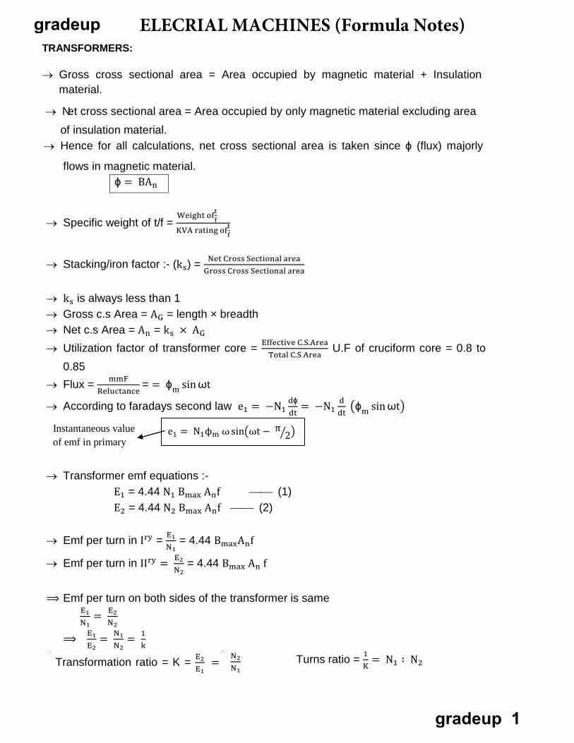
TRANSFORMERS: → Gross cross sectional area = Area occupied by magnetic material + Insulation material. → Net cross sectional area = Area occupied by only magnetic material excluding area of insulation material. → Hence for all calculations, net cross sectional area is taken since ϕ (flux) majorly flows in magnetic material. ϕ = BA n t f → Specific weight of t/f = K We VA ig ra ht ti of n f g of t → Stacking/iron factor :- (k s ) = Net Cross Sectional area Gross Cross Sectional area Total C.S Area → k s is always less than 1 → Gross c.s Area = A G = length × breadth → Net c.s Area = A n = k s × A G → Utilization factor of transformer core = Effective C.S.Area U.F of cruciform core = 0.8 to 0.85 → Flux = mmF Reluctance = = ϕ m sin ωt → According to faradays second law e 1 = −N 1 dϕ dt = −N 1 d dt �ϕ m sin ωt� → Transformer emf equations :- E 1 = 4.44 N 1 B max A n f (1) E 2 = 4.44 N 2 B max A n f (2) N 1 → Emf per turn in I ry = E 1 = 4.44 B max A n f N 2 → Emf per turn in II ry = E 2 = 4.44 B max A n f ⟹ Emf per turn on both sides of the transformer is same E 1 N 1 N 2 = E 2 ⟹ E 1 E 2 = N 1 N 2 = 1 k Transformation ratio = K = E 2 E 1 = Instantaneous value of emf in primary e 1 = N 1 ϕ m ω sin�ωt − π � 2 � N 2 N 1 Turns ratio = 1 K = N 1 ∶ N 2 ELECRIAL MACHINES (Formula Notes) gradeup gradeup 1
Transcript of gradeup ELECRIAL MACHINES (Formula Notes)€¦ · TRANSFORMERS: → Gross cross sectional area =...
TRANSFORMERS:
→ Gross cross sectional area = Area occupied by magnetic material + Insulation material.
→ Net cross sectional area = Area occupied by only magnetic material excluding area of insulation material.
→ Hence for all calculations, net cross sectional area is taken since ϕ (flux) majorly
flows in magnetic material. ϕ = BAn
tf→ Specific weight of t/f =
K
We
VA
i
g
ra
ht
t
i
of
n fg oft
→ Stacking/iron factor :- (ks) = Net Cross Sectional areaGross Cross Sectional area
Total C.S Area
→ ks is always less than 1 → Gross c.s Area = AG = length × breadth → Net c.s Area = An = ks × AG → Utilization factor of transformer core = Effective C.S.Area U.F of cruciform core = 0.8 to
0.85 → Flux = mmF
Reluctance = = ϕm sin ωt
→ According to faradays second law e1 = −N1dϕdt
= −N1ddt
�ϕm sin ωt�
→ Transformer emf equations :- E1 = 4.44 N1 Bmax Anf (1) E2 = 4.44 N2 Bmax Anf (2)
N1→ Emf per turn in Iry = E1 = 4.44 BmaxAnf
N2→ Emf per turn in IIry = E2 = 4.44 Bmax An f
⟹ Emf per turn on both sides of the transformer is same E1N1 N2
= E2
⟹ E1E2
= N1N2
= 1k
Transformation ratio = K = E2E1
=
Instantaneous value of emf in primary
e1 = N1ϕm ω sin�ωt − π�2�
N2N1
Turns ratio = 1K
= N1 ∶ N2
ELECRIAL MACHINES (Formula Notes)gradeup
gradeup 1
→ For an ideal two-winding transformer with primary voltage V1 applied across N1 primary turns and secondary voltage V2 appearing across N2 secondary turns: V1 / V2 = N1 / N2
→ The primary current I1 and secondary current I2 are related by: I1 / I2 = N2 / N1 = V2 / V1
→ For an ideal step-down auto-transformer with primary voltage V1 applied across (N1 + N2) primary turns and secondary voltage V2 appearing across N2 secondary turns: V1 / V2 = (N1 + N2) / N2
→ The primary (input) current I1 and secondary (output) current I2 are related by: I1 / I2 = N2 / (N1 + N2) = V2 / V1.
→ For a single-phase transformer with rated primary voltage V1, rated primary current I1, rated secondary voltage V2 and rated secondary current I2, the voltampere rating S is: S = V1I1 = V2I2
→ For a balanced m-phase transformer with rated primary phase voltage V1, rated primary current I1, rated secondary phase voltage V2 and rated secondary current I2, the voltampere rating S is: S = mV1I1 = mV2I2
→ The primary circuit impedance Z1 referred to the secondary circuit for an ideal transformer with N1 primary turns and N2 secondary turns is: Z12 = Z1(N2 / N1)2
→ During operation of transformer :-
Bm ∝ E1f f
∝ V1
Bmax = constant ⟹ V1f
= constant
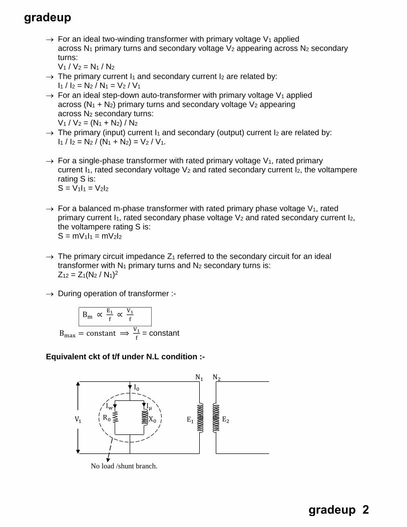
Equivalent ckt of t/f under N.L condition :-
No load /shunt branch.
N1 N2
E2 E1 V1
I0
Iw R0 X0
Iµ
gradeup
gradeup 2
→ No load current = I0 = Iµ + Iw = I0 �−ϕ0
Iw = I0 cos ϕ0 Iµ = I0 sin ϕ0 → No load power = v1I0 cos ϕ0 = v1Iw = Iron losses.
R0 = v1Iw1
; X0 = v1Iµ
⟹ Iw = No load powerV1
Transferring from 𝐈𝐈𝐈𝐈𝐫𝐫𝐫𝐫 to 𝐈𝐈𝐫𝐫𝐫𝐫:-
I 2 2 R2 = I
12 R
21
R 21 = R2 �I2�
2
K2
I1
= R2
∴ R 21 =
KR2
2
From 𝐈𝐈𝐫𝐫𝐫𝐫 to 𝐈𝐈𝐈𝐈𝐫𝐫𝐫𝐫 :- I 1 2R1 = I
2 2. R
11
R 11 = I
1 2
I 2 2 . R1
R 1 1 = R1. K2
→ Total resistance ref to primary = R1 + R 21
R01 = R1 + R2/k2 → Total resistance ref to secondary = R2 + R
1 1
R02 = R2 + k2R1 → Total Cu loss = I
12R01
Or I
2 2 R02
R R21
1
Per unit resistance drops :-
E1→ P.U primary resistance drop = I1R1
E2→ P.U secondary resistance drop = I2 R2
E1→ Total P.U resistance drop ref to Iry = I1R01
E2→ Total P.U resistance drop ref to IIry = I2 R02
→ The P.U resistance drops on both sides of the t/f is same I1 R01 = I2R02
E1 E2
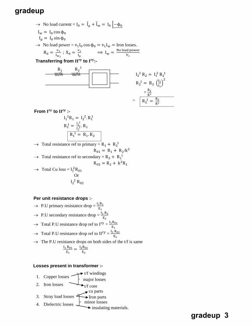
Losses present in transformer :-
1. Copper losses
2. Iron losses
3. Stray load losses
4. Dielectric losses
major losses
Iron parts minor losses
t/f windings
t/f core cu parts
insulating materials.
gradeup
gradeup 3
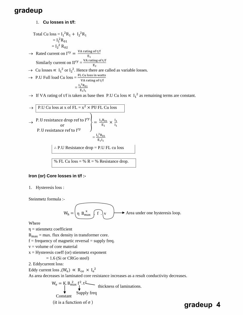
1. Cu losses in t/f:
Total Cu loss = I 1 2R1 + I
2 2R1
= I 12R01
E1
= I 2 2 R02
→ Rated current on Iry = VA rating of t/f
E2Similarly current on IIry = VA rating of t/f
VA rating of t/f
→ Cu losses ∝ I 1 2 or I
2 2. Hence there are called as variable losses.
→ P.U Full load Cu loss = FL Cu loss in watts
= I 1 2R01E1I1
→ If VA rating of t/f is taken as base then P.U Cu loss ∝ I 1 2 as remaining terms are constant.
→ P.U Cu loss at x of FL = x2 × PU FL Cu loss
→ P. U resistance drop ref to Iry
or P. U resistance ref to Iry
� = I1R01E1 I1
× I1
= I 1 2R01E1I1
∴ P.U Resistance drop = P.U FL cu loss
% FL Cu loss = % R = % Resistance drop.
Iron (or) Core losses in t/f :-
1. Hysteresis loss :
Steinmetz formula :-
Where η = stienmetz coefficient Bmax = max. flux density in transformer core. f = frequency of magnetic reversal = supply freq. v = volume of core material x = Hysteresis coeff (or) stienmetz exponent
= 1.6 (Si or CRGo steel) 2. Eddycurrent loss:Eddy current loss ,(We) ∝ Rce × I
e 2
As area decreases in laminated core resistance increases as a result conductivity decreases.
We = K. B ma
2x f 2. t2
Constant Supply freq
thickness of laminations.
Area under one hysteresis loop. xη B max . f . v Wh =
(it is a function of σ )
gradeup
gradeup 4
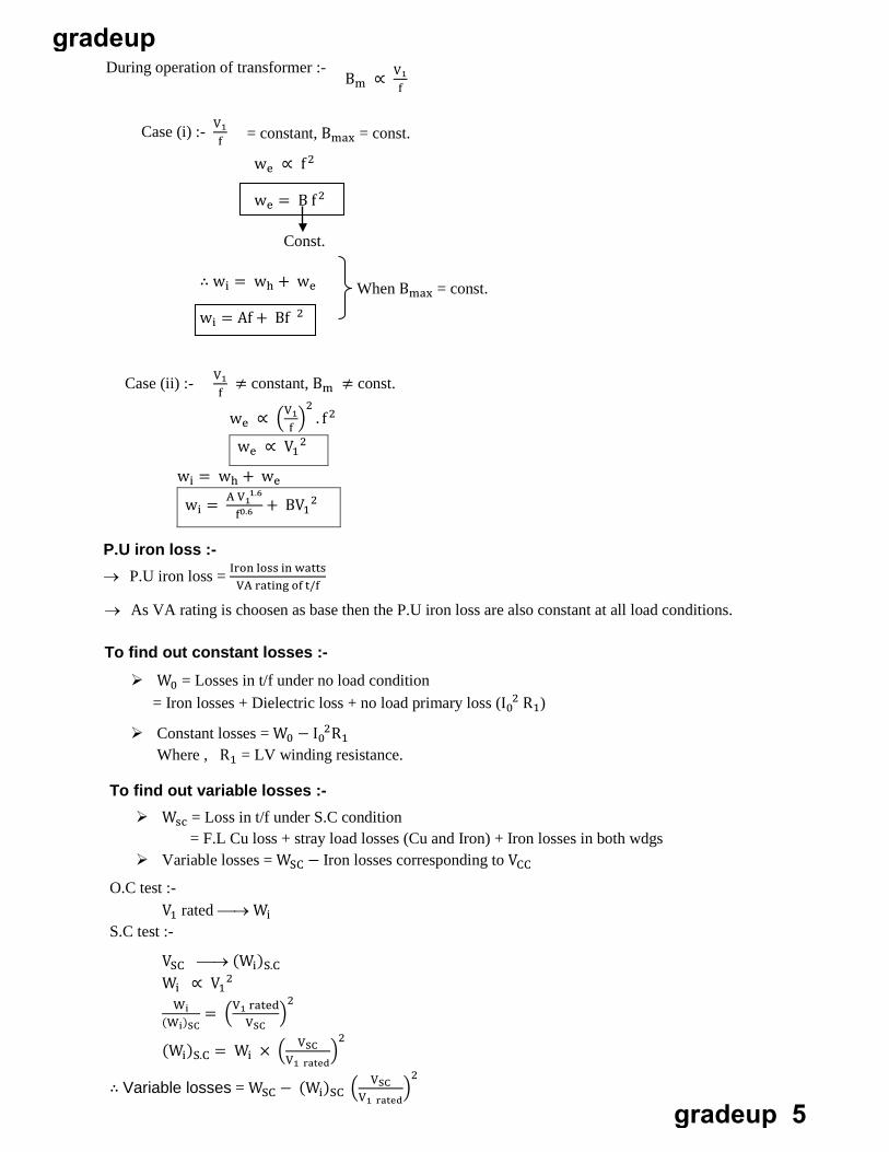
During operation of transformer :- Bm ∝ V1
f
fCase (i) :- V1 = constant, Bmax = const.
we ∝ f 2
we = B f 2
Const.
∴ wi = wh + we
wi = Af + Bf 2
When Bmax = const.
Case (ii) :- V1f
≠ constant, Bm ≠ const.
we ∝ �V1f
�2
. f 2
we ∝ V1 2
wi = wh + we
wi = A V0
.1
6
1.6
f+ BV1
2
VA rating of t/f
P.U iron loss :- → P.U iron loss = Iron loss in watts
→ As VA rating is choosen as base then the P.U iron loss are also constant at all load conditions.
To find out constant losses :- W0 = Losses in t/f under no load condition
= Iron losses + Dielectric loss + no load primary loss (I 0 2 R1)
Constant losses = W0 − I 0 2R1
Where , R1 = LV winding resistance.
To find out variable losses :- Wsc = Loss in t/f under S.C condition
= F.L Cu loss + stray load losses (Cu and Iron) + Iron losses in both wdgs Variable losses = WSC − Iron losses corresponding to VCC
O.C test :- V1 rated → Wi
S.C test :-
VSC → (Wi)S.C Wi ∝ V1
2 Wi
(Wi)SC= �V1 rated
VSC�
2
(Wi)S.C = Wi × � VSCV1 rated
�2
∴ Variable losses = WSC − (Wi)SC � VSCV1 rated
�2
gradeup
gradeup 5
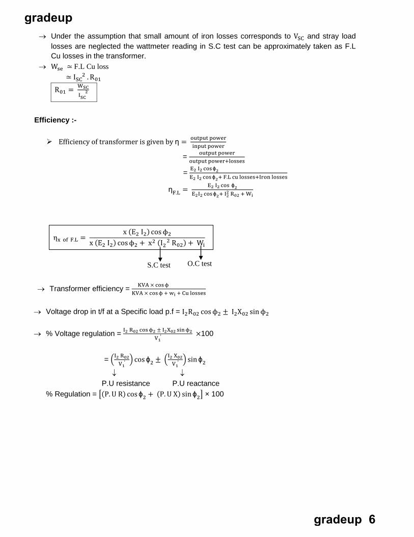
→ Under the assumption that small amount of iron losses corresponds to VSC and stray load losses are neglected the wattmeter reading in S.C test can be approximately taken as F.L Cu losses in the transformer.
→ Wse ≃ F.L Cu loss ≃ I
S C 2 . R01
R01 = I
W
SC2
SC
Efficiency :-
Efficiency of transformer is given by η = output powerinput power
= output poweroutput power+losses
= E2 I2 cos ϕ2E2 I2 cos ϕ2+ F.L cu losses+Iron losses
ηF.L = E2 I2 cos ϕ22E2I2 cos ϕ2+ I2 R02 + Wi
→ Transformer efficiency = KVA × cos ϕ KVA × cos ϕ + wi + Cu losses
ηx of F.L = x (E2 I2) cos ϕ2
x (E2 I2) cos ϕ2 + x2 (I 2 2 R02) + Wi
O.C test S.C test
V 1 ′
→ Voltage drop in t/f at a Specific load p.f = I2R02 cos ϕ2 ± I2X02 sin ϕ2
→ % Voltage regulation = I2 R02 cos ϕ2 ± I2X02 sin ϕ2 ×100
= �I2 VR
′02
1� cos ϕ2 ± �I2 X02
V 1 ′ � sin ϕ2
↓ P.U resistance
↓ P.U reactance
% Regulation = �(P. U R) cos ϕ2 + (P. U X) sin ϕ2� × 100
gradeup
gradeup 6
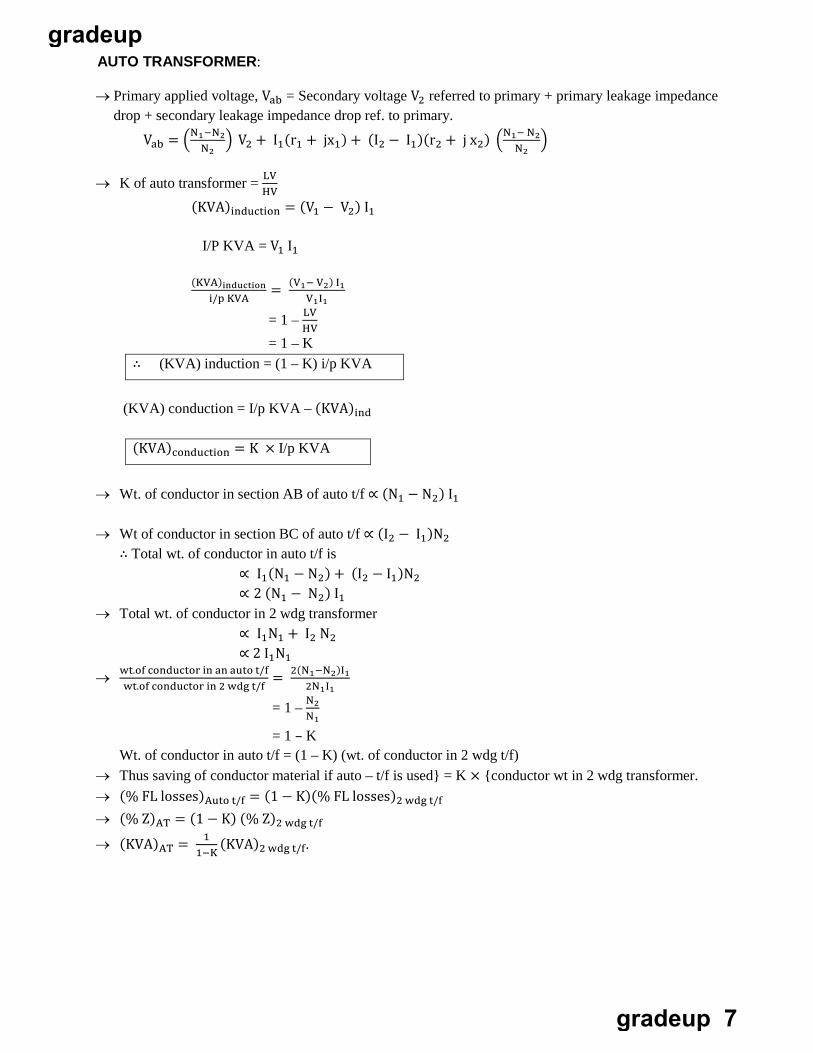
AUTO TRANSFORMER:
→ Primary applied voltage, Vab = Secondary voltage V2 referred to primary + primary leakage impedance drop + secondary leakage impedance drop ref. to primary.
Vab = �N1−N2N2
� V2 + I1(r1 + jx1) + (I2 − I1)(r2 + j x2) �N1− N2N2
�
→ K of auto transformer = LV HV
(KVA)induction = (V1 − V2) I1
I/P KVA = V1 I1
(KVA)inductioni/p KVA V1I1
= (V1− V2) I1
HV = 1 – LV = 1 – K
∴ (KVA) induction = (1 – K) i/p KVA
(KVA) conduction = I/p KVA – (KVA)ind
(KVA)conduction = K × I/p KVA
→ Wt. of conductor in section AB of auto t/f ∝ (N1 − N2) I1
→ Wt of conductor in section BC of auto t/f ∝ (I2 − I1)N2 ∴ Total wt. of conductor in auto t/f is
∝ I1(N1 − N2) + (I2 − I1)N2 ∝ 2 (N1 − N2) I1
→ Total wt. of conductor in 2 wdg transformer ∝ I1N1 + I2 N2 ∝ 2 I1N1
→ wt.of conductor in an auto t/fwt.of conductor in 2 wdg t/f 2N1I1
= 2(N1−N2)I1
N1 = 1 – N2
= 1 – K Wt. of conductor in auto t/f = (1 – K) (wt. of conductor in 2 wdg t/f)
→ Thus saving of conductor material if auto – t/f is used} = K × {conductor wt in 2 wdg transformer. → (% FL losses)Auto t/f = (1 − K)(% FL losses)2 wdg t/f → (% Z)AT = (1 − K) (% Z)2 wdg t/f
→ (KVA)AT = 11−K
(KVA)2 wdg t/f.
gradeup
gradeup 7
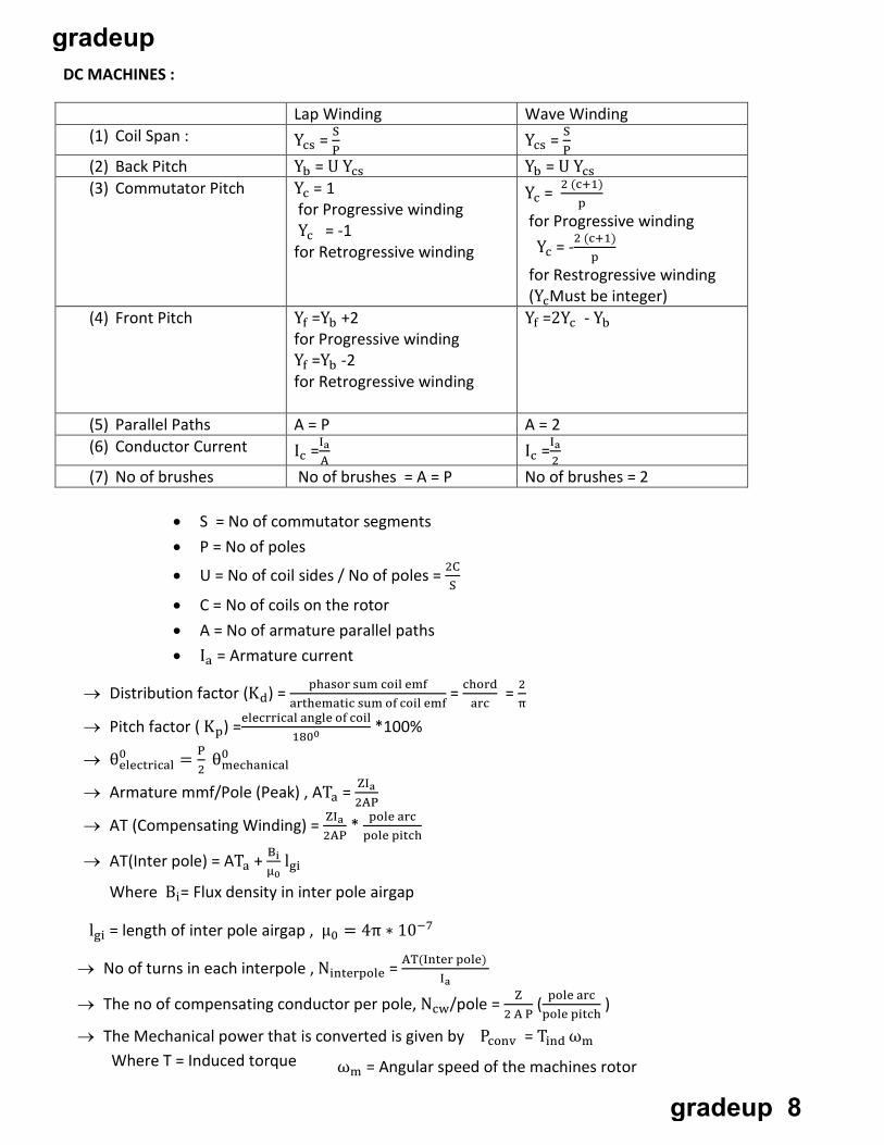
DC MACHINES :
Lap Winding Wave Winding (1) Coil Span : Ycs = S
PYcs = S
P(2) Back Pitch Yb = U Ycs Yb = U Ycs (3) Commutator Pitch Yc = 1
for Progressive winding Yc = -1 for Retrogressive winding
Yc = 2 (c+1)p
for Progressive winding Yc = -2 (c+1)
p for Restrogressive winding (YcMust be integer)
(4) Front Pitch Yf =Yb +2 for Progressive winding Yf =Yb -2 for Retrogressive winding
Yf =2Yc - Yb
(5) Parallel Paths A = P A = 2 (6) Conductor Current Ic =Ia
AIc =Ia
2(7) No of brushes No of brushes = A = P No of brushes = 2
• S = No of commutator segments• P = No of poles
• U = No of coil sides / No of poles = 2CS
• C = No of coils on the rotor• A = No of armature parallel paths• Ia = Armature current
→ Distribution factor (Kd) = phasor sum coil emfarthematic sum of coil emf
= chordarc
= 2π
→ Pitch factor ( Kp) =elecrrical angle of coil1800 *100%
→ θ0electrical 2
= P θ0mechanical
→ Armature mmf/Pole (Peak) , ATa = ZIa2AP
2AP→ AT (Compensating Winding) = ZIa * pole arc
pole pitch
→ AT(Inter pole) = ATa + Bi lgiµ0
Where Bi= Flux density in inter pole airgap
lgi = length of inter pole airgap , µ0 = 4π ∗ 10−7
→ No of turns in each interpole , Ninterpole = AT(Inter pole) Ia
→ The no of compensating conductor per pole, Ncw/pole = Z2 A P
( pole arcpole pitch
)
→ The Mechanical power that is converted is given by Pconv = Tind ωm Where T = Induced torque ωm = Angular speed of the machines rotor
gradeup
gradeup 8
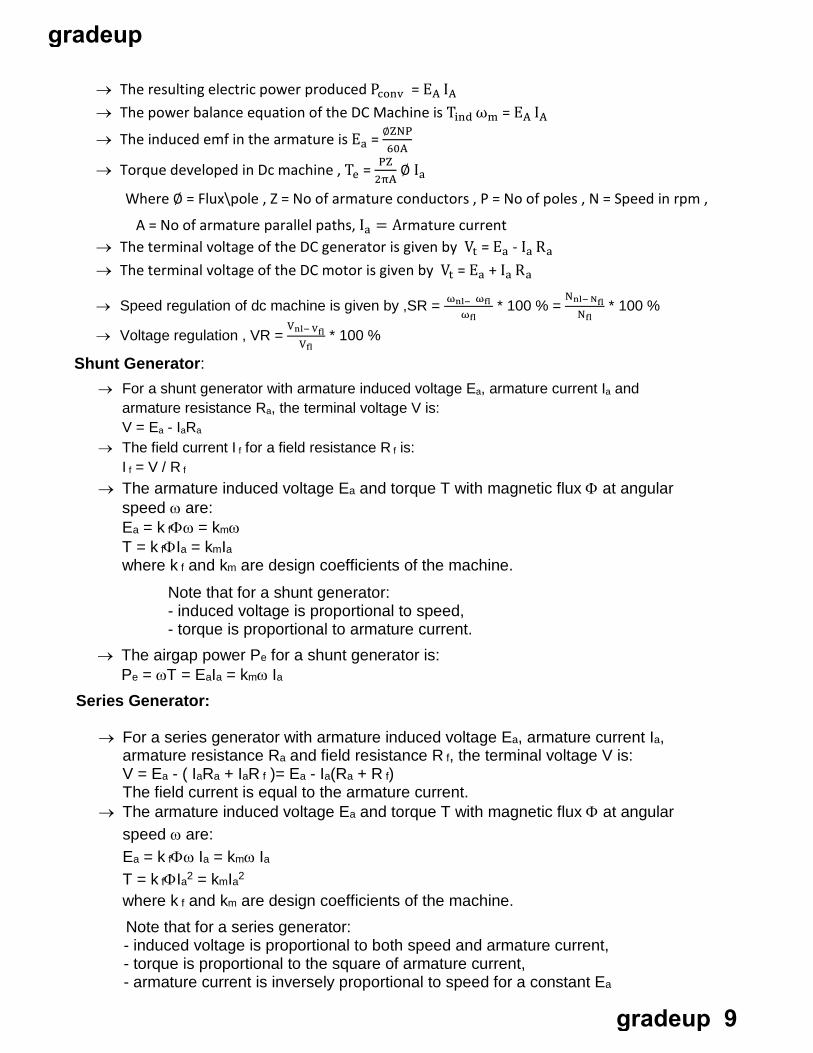
→ The resulting electric power produced Pconv = EA IA → The power balance equation of the DC Machine is Tind ωm = EA IA
→ The induced emf in the armature is Ea = ∅ZNP60A
→ Torque developed in Dc machine , Te = PZ2πA
∅ Ia
Where ∅ = Flux\pole , Z = No of armature conductors , P = No of poles , N = Speed in rpm ,
A = No of armature parallel paths, Ia = Armature current → The terminal voltage of the DC generator is given by Vt = Ea - Ia Ra → The terminal voltage of the DC motor is given by Vt = Ea + Ia Ra
ωfl → Speed regulation of dc machine is given by ,SR = ωn
l− ωfl * 100 % =
Nnl− NflNfl
* 100 %
→ Voltage regulation , VR = Vnl− Vfl
Vfl* 100 %
Shunt Generator: → For a shunt generator with armature induced voltage Ea, armature current Ia and
armature resistance Ra, the terminal voltage V is: V = Ea - IaRa
→ The field current I f for a field resistance R f is: I f = V / R f
→ The armature induced voltage Ea and torque T with magnetic flux Φ at angular speed ω are: Ea = k fΦω = kmω T = k fΦIa = kmIa where k f and km are design coefficients of the machine.
Note that for a shunt generator: - induced voltage is proportional to speed, - torque is proportional to armature current.
→ The airgap power Pe for a shunt generator is: Pe = ωT = EaIa = kmω Ia
Series Generator:
→ For a series generator with armature induced voltage Ea, armature current Ia, armature resistance Ra and field resistance R f, the terminal voltage V is: V = Ea - ( IaRa + IaR f )= Ea - Ia(Ra + R f) The field current is equal to the armature current.
→ The armature induced voltage Ea and torque T with magnetic flux Φ at angular speed ω are: Ea = k fΦω Ia = kmω Ia T = k fΦIa2 = kmIa2 where k f and km are design coefficients of the machine.
Note that for a series generator: - induced voltage is proportional to both speed and armature current, - torque is proportional to the square of armature current, - armature current is inversely proportional to speed for a constant Ea
gradeup
gradeup 9
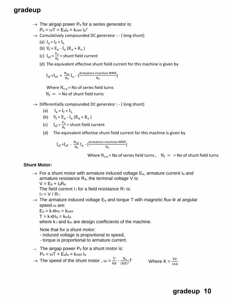
→ The airgap power Pe for a series generator is: Pe = ωT = EaIa = kmω Ia2
→ Cumulatively compounded DC generator : - ( long shunt) (a) Ia = If + IL (b) Vt = Ea - Ia (Ra + Rs )
(c) Isf = VxRf
= shunt field current
(d) The equivalent effective shunt field current for this machine is given by
Isf =Isf + Nse I - (Armature reaction MMFNf
a Nf)
Where Ns e = No of series field turns Nf = = No of shunt field turns
→ Differentially compounded DC generator : - ( long shunt) (a) Ia = If + IL (b) Vt = Ea - Ia (Ra + Rs )
(c) Isf = VxRf
= shunt field current
(d) The equivalent effective shunt field current for this machine is given by
Isf =Isf - NseNf
Ia - (Armature reaction MMFNf
)
Where Ns e = No of series field turns , Nf = = No of shunt field turns
Shunt Motor:
→ For a shunt motor with armature induced voltage Ea, armature current Ia and armature resistance Ra, the terminal voltage V is: V = Ea + IaRa The field current I f for a field resistance R f is: I f = V / R f
→ The armature induced voltage Ea and torque T with magnetic flux Φ at angular speed ω are: Ea = k fΦω = kmω T = k fΦIa = kmIa where k f and km are design coefficients of the machine.
Note that for a shunt motor: - induced voltage is proportional to speed, - torque is proportional to armature current.
→ The airgap power Pe for a shunt motor is: Pe = ωT = EaIa = kmω Ia
→ The speed of the shunt motor , ω = VK∅
- Ra(K∅)2T Where K = PZ
2πA
gradeup
gradeup 10
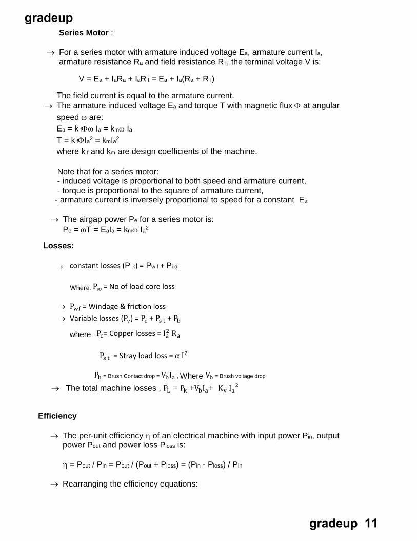
Series Motor :
→ For a series motor with armature induced voltage Ea, armature current Ia, armature resistance Ra and field resistance R f, the terminal voltage V is:
V = Ea + IaRa + IaR f = Ea + Ia(Ra + R f)
The field current is equal to the armature current. → The armature induced voltage Ea and torque T with magnetic flux Φ at angular
speed ω are: Ea = k fΦω Ia = kmω Ia T = k fΦIa2 = kmIa2 where k f and km are design coefficients of the machine.
Note that for a series motor: - induced voltage is proportional to both speed and armature current, - torque is proportional to the square of armature current, - armature current is inversely proportional to speed for a constant Ea
→ The airgap power Pe for a series motor is: Pe = ωT = EaIa = kmω Ia2
Losses:
→ constant losses (P k) = Pw f + Pi o
Where, Pio = No of load core loss
→ Pwf = Windage & friction loss → Variable losses (Pv) = Pc + Ps t + Pb
where Pc= Copper losses = Ia2 Ra
Ps t = Stray load loss = α I2
Pb = Brush Contact drop = VbIa , Where Vb = Brush voltage drop
→ The total machine losses , PL = Pk +VbIa+ Kv Ia2
Efficiency
→ The per-unit efficiency η of an electrical machine with input power Pin, output power Pout and power loss Ploss is:
η = Pout / Pin = Pout / (Pout + Ploss) = (Pin - Ploss) / Pin
→ Rearranging the efficiency equations:
gradeup
gradeup 11
Pin = Pout + Ploss = Pout / η = Ploss / (1 - η)
Pout = Pin - Ploss = ηPin = ηPloss / (1 - η)
Ploss = Pin - Pout = (1 - η)Pin = (1 - η)Pout / η
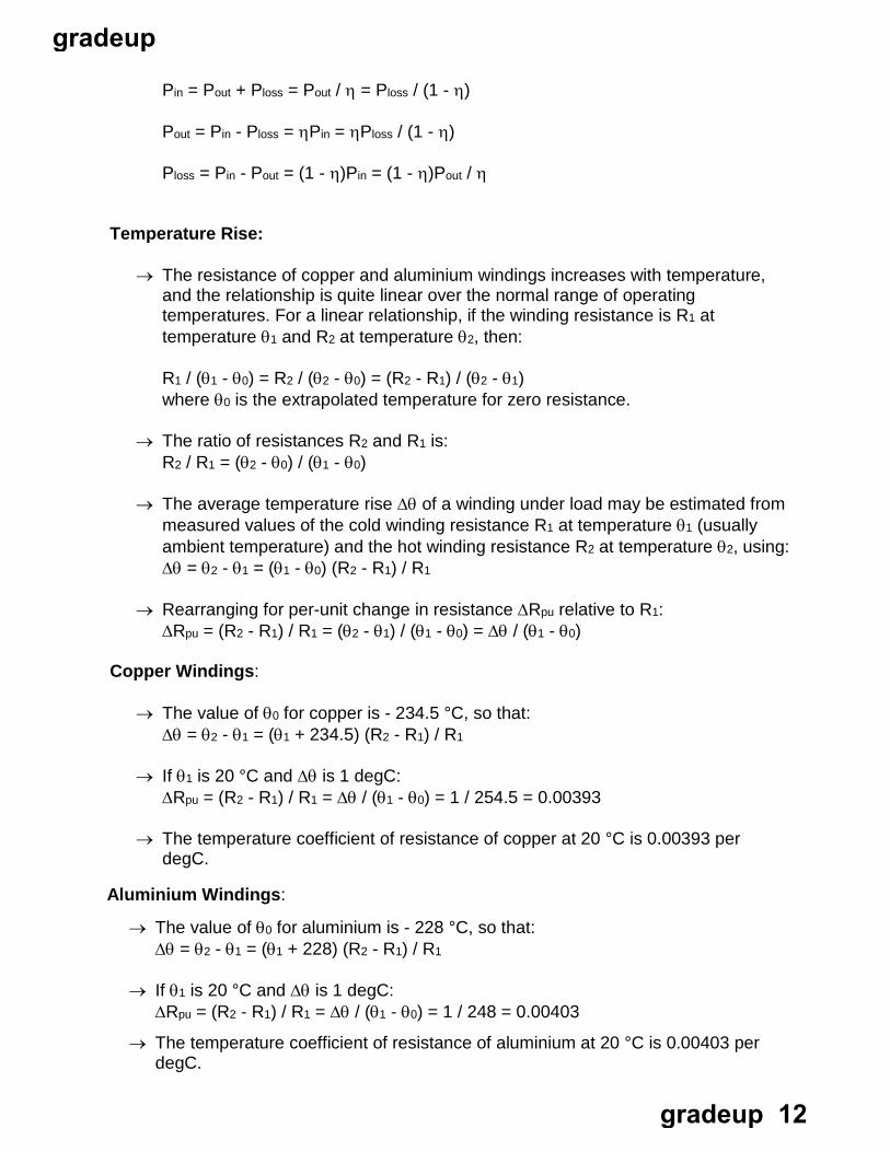
Temperature Rise:
→ The resistance of copper and aluminium windings increases with temperature, and the relationship is quite linear over the normal range of operating temperatures. For a linear relationship, if the winding resistance is R1 at temperature θ1 and R2 at temperature θ2, then:
R1 / (θ1 - θ0) = R2 / (θ2 - θ0) = (R2 - R1) / (θ2 - θ1) where θ0 is the extrapolated temperature for zero resistance.
→ The ratio of resistances R2 and R1 is: R2 / R1 = (θ2 - θ0) / (θ1 - θ0)
→ The average temperature rise ∆θ of a winding under load may be estimated from measured values of the cold winding resistance R1 at temperature θ1 (usually ambient temperature) and the hot winding resistance R2 at temperature θ2, using: ∆θ = θ2 - θ1 = (θ1 - θ0) (R2 - R1) / R1
→ Rearranging for per-unit change in resistance ∆Rpu relative to R1: ∆Rpu = (R2 - R1) / R1 = (θ2 - θ1) / (θ1 - θ0) = ∆θ / (θ1 - θ0)
Copper Windings:
→ The value of θ0 for copper is - 234.5 °C, so that: ∆θ = θ2 - θ1 = (θ1 + 234.5) (R2 - R1) / R1
→ If θ1 is 20 °C and ∆θ is 1 degC: ∆Rpu = (R2 - R1) / R1 = ∆θ / (θ1 - θ0) = 1 / 254.5 = 0.00393
→ The temperature coefficient of resistance of copper at 20 °C is 0.00393 per degC.
Aluminium Windings:
→ The value of θ0 for aluminium is - 228 °C, so that: ∆θ = θ2 - θ1 = (θ1 + 228) (R2 - R1) / R1
→ If θ1 is 20 °C and ∆θ is 1 degC: ∆Rpu = (R2 - R1) / R1 = ∆θ / (θ1 - θ0) = 1 / 248 = 0.00403
→ The temperature coefficient of resistance of aluminium at 20 °C is 0.00403 per degC.
gradeup
gradeup 12
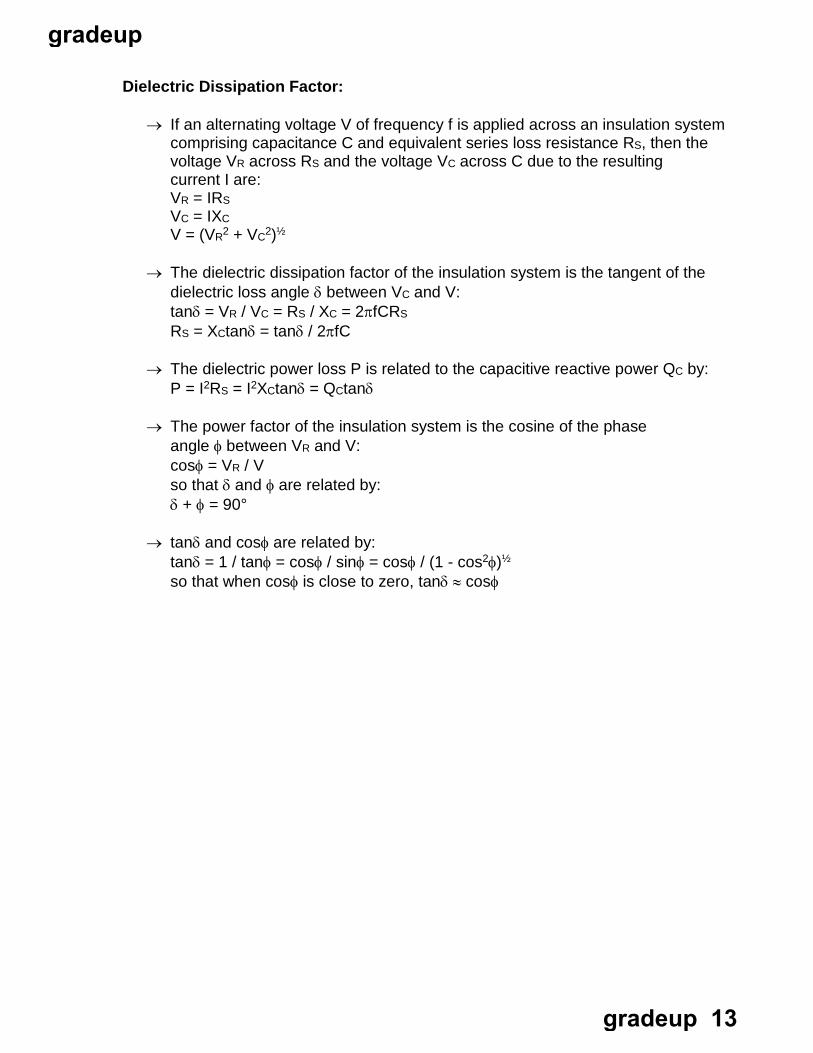
Dielectric Dissipation Factor:
→ If an alternating voltage V of frequency f is applied across an insulation system comprising capacitance C and equivalent series loss resistance RS, then the voltage VR across RS and the voltage VC across C due to the resulting current I are: VR = IRS VC = IXC V = (VR2 + VC2)½
→ The dielectric dissipation factor of the insulation system is the tangent of the dielectric loss angle δ between VC and V: tanδ = VR / VC = RS / XC = 2πfCRS RS = XCtanδ = tanδ / 2πfC
→ The dielectric power loss P is related to the capacitive reactive power QC by: P = I2RS = I2XCtanδ = QCtanδ
→ The power factor of the insulation system is the cosine of the phase angle φ between VR and V: cosφ = VR / V so that δ and φ are related by: δ + φ = 90°
→ tanδ and cosφ are related by: tanδ = 1 / tanφ = cosφ / sinφ = cosφ / (1 - cos2φ)½ so that when cosφ is close to zero, tanδ ≈ cosφ
gradeup
gradeup 13
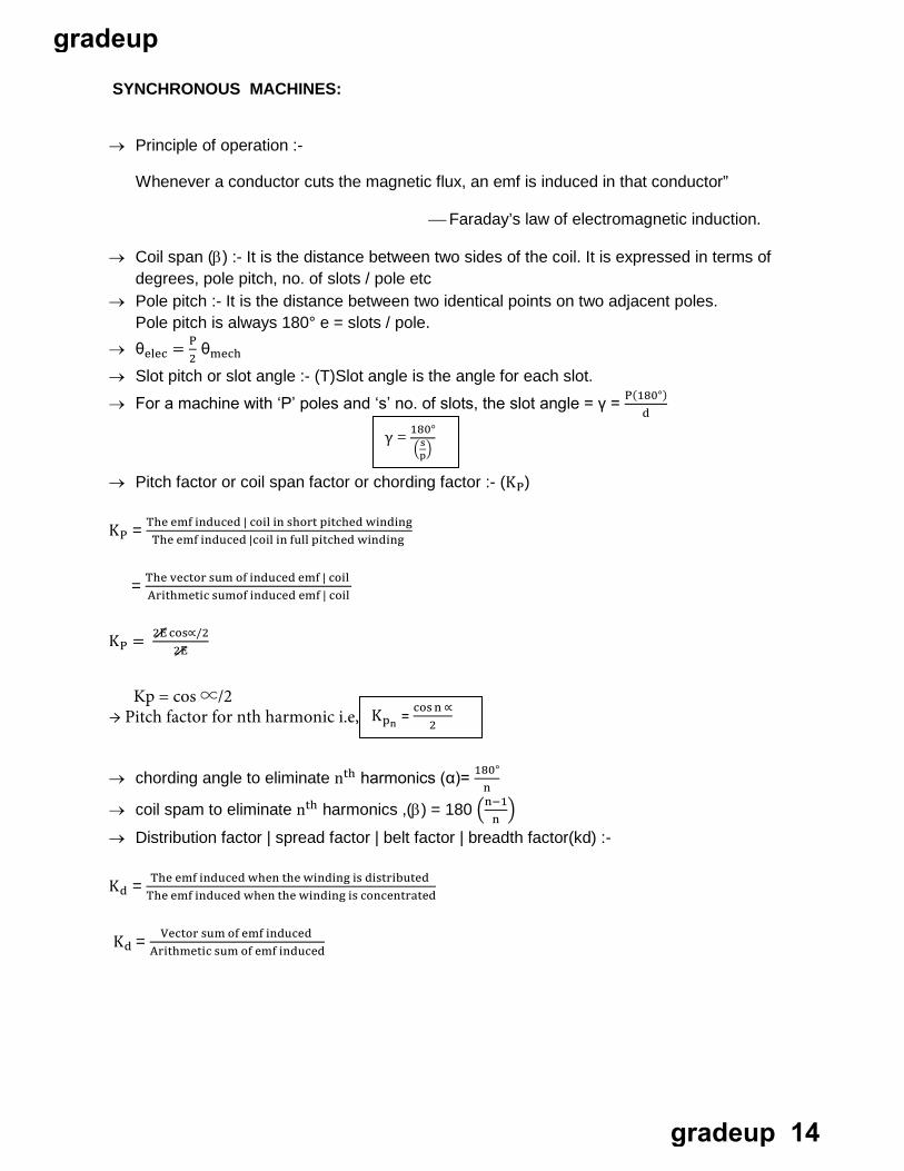
SYNCHRONOUS MACHINES:
→ Principle of operation :-
Whenever a conductor cuts the magnetic flux, an emf is induced in that conductor”
Faraday’s law of electromagnetic induction.
→ Coil span (β) :- It is the distance between two sides of the coil. It is expressed in terms of degrees, pole pitch, no. of slots / pole etc
→ Pole pitch :- It is the distance between two identical points on two adjacent poles. Pole pitch is always 180° e = slots / pole.
→ θelec = P2 θmech
→ Slot pitch or slot angle :- (T)Slot angle is the angle for each slot.
→ For a machine with ‘P’ poles and ‘s’ no. of slots, the slot angle = γ = P(180°)d
→ Pitch factor or coil span factor or chording factor :- (KP)
KP = The emf induced | coil in short pitched windingThe emf induced |coil in full pitched winding
Arithmetic sumof induced emf | coil = The vector sum of induced emf | coil
KP = 2E cos∝/22E
→ chording angle to eliminate nth harmonics (α)= 180° n
→ coil spam to eliminate nth harmonics ,(β) = 180 �n−1� n
→ Distribution factor | spread factor | belt factor | breadth factor(kd) :-
Kd = The emf induced when the winding is distributedThe emf induced when the winding is concentrated
Kd = Vector sum of emf induced Arithmetic sum of emf induced
p� �γ = 18
s0°
K pn = cos n ∝2
Kp = cos ∝/2 → Pitch factor for nth harmonic i.e,
gradeup
gradeup 14
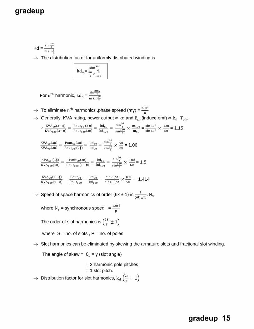
Kd = sinmγ
2m sinγ
2
→ The distribution factor for uniformly distributed winding is
mnγ2For nth harmonic, kdn =
s
m
in
s 2innγ
→ To eliminate nth harmonics ,phase spread (mγ) = 360° n
→ Generally, KVA rating, power output ∝ kd and Eph(induce emf) ∝ kd . Tph.
∴ KVA60(3− ϕ)KVA120(3− ϕ) = Pout60 (3 ϕ)
Pout120(3ϕ) = kd60kd120
= sin60
2
2sin120 m60
× m120 = sin 30°sin 60° 60
× 120 = 1.15
KVA60(3ϕ)KVA90(2ϕ) = Pout60(3ϕ)
Pout90°(2ϕ) = kd60kd90
= sin60
2
2sin90 60
× 90 = 1.06
KVA60 (3ϕ)KVA180(1ϕ)
= Pout60(3ϕ)Pout180 (1− ϕ) = kd60
kd180=
sin602
2sin180 60
× 180 = 1.5
KVA90(2− ϕ)KVA180(1− ϕ) = Pout90
Pout180= kd90
kd180= sin90⁄2
sin180⁄2× 180
90= 1.414
→ Speed of space harmonics of order (6k ± 1) is 1(6k ±1) . Ns
where Ns = synchronous speed = 120 fp
The order of slot harmonics is �2SP
± 1�
where S = no. of slots , P = no. of poles
→ Slot harmonics can be eliminated by skewing the armature slots and fractional slot winding.
The angle of skew = θs = γ (slot angle)
= 2 harmonic pole pitches = 1 slot pitch.
→ Distribution factor for slot harmonics, kd �2sp
± 1�
kd4 = s
im mr2
mr2 × π
180
gradeup
gradeup 15
m γ2Is kd1 =
s
m
in
sinγ2 i.e., same that of fundamental
→ Pith factor for slot harmonics, kp �2sp
± 1� = kp1 = cos ∝�2
→ The synchronous speed Ns and synchronous angular speed of a machine with p pole pairs running on a supply of frequency fs are:
ωs = 2πfs / p
NS→ Slip S = NS− N
Where NS = 120 f = synchronous speed p
→ The magnitude of voltage induced in a given stator phase is Ea= √2 π Nc ∅ f = K∅ω Where K = constant
→ The output power Pm for a load torque Tm is:
Pm = ωsTm
→ The rated load torque TM for a rated output power PM is:
TM = PM / ωs = PM p/ 2πfs = 120PM / 2πNs
Synchronous Generator:
→ For a synchronous generator with stator induced voltage Es, stator current Is and synchronous impedance Zs, the terminal voltage V is:
V = E - IsZs = Es - Is(Rs + jXs)
where Rs is the stator resistance and Xs is the synchronous reactance
E = �(V cos ϕ + Ia Ra)2 + (V sin ϕ ± Ia Xs)2 + ⇒ lag p.f − ⇒ leading p.f.
gradeup
gradeup 16
Synchronous Motor:
→ For a synchronous motor with stator induced voltage Es, stator current Is and synchronous impedance Zs, the terminal voltage V is:
V = Es + IsZs = Es + Is(Rs + jXs) where Rs is the stator resistance and Xs is the synchronous reactance
Voltage regulation :
→ % regulation = |E|− |V||V| ×100
V
E – V = IaZs ∴ % regulation = E − V
= Ia Zs × 100 V
∴ regulation ∝ Zs ∴ As Zs increases, voltages regulation increases.
→ Condition for zero | min. voltage regulation is, Cos (θ + ϕ) = − Ia Zs 2V
→ Condition for max. Voltage regulation is, ϕ = θ
→ Short circuit ratio (SCR) = IfmIfa
= 1Zs(adjusted)|unit
= 1Xs(adjusted)|unit
SCR ∝ 1Xa
∝ 1Armature reaction
Voltage regulation ∝ Armature reaction
∴ SCR ∝ 1Voltage regulation
∴ Small value of SCR represent poor regulation.
ϕa = armature mmfreluctance
But reluctance ∝ Air gap
∴ ϕa = armature mmfairgap
ϕa ∝ 1Air gap length
Armature reaction ∝ ϕa ∝ 1Airgap length
gradeup
gradeup 17
∴ SCR ∝ 1Armature reaction
∝ Airgap length
Air gap length ∝ SCR
∴ machine size ∝ SCR. Cost ∝ SCR
Power = EVXs
sin δ
⇒ P ∝ 1Xs
∝ SCR
∴ Large value of SCR represent more power output. → Synchronizing power coefficient or stability factor Psy is given as
dδd
dδ�EV
XsPsy = dp = sin δ�
= EVXs
cos δ
Psy is a measure of stability ∴ stability ∝ Psy
But Psy ∝ 1Xs
∝ SCR
Stability ∝ SCR ∝ Air gap length
→ When the stator mmf is aligned with the d – axis of field poles then flux ϕd perpole is set up
minimum current √3 Ia(min )
and the effective reactance offered by the alternator is Xd.
Xd = maximum Voltage = (Vt)line (at min. Ia ) = Direct axis reactance
→ When the stator mmf is aligned with the q – axis of field poles then flux ϕq per pole is set up and the effective reactance offered by the alternator is Xq.
Xq = minimum voltge maximum voltage √3 Ia(max )
= Vt line (at maximum Ia ) = Quadrature axis reactance
Power ∝ SCR
∴ Stability ∝ SCR
∴ Stability ∝ Air gap length
gradeup
gradeup 18
→ Cylindrical rotor Synchronous machine ,
The per phase power delivered to the infinite bus is given by P = Ef VtXs
sin δ
→ Salient pole synchronous machine ,
The per phase power delivered to the infinite bus is given by
Xd 2 Xq
1Xd
P = Ef Vt sin δ + V t 2
� 1 − � sin 2δ
Condition for max. power:- → For cylindrical rotor machine :-
At constant Vt and Ef, the condition for max. power is obtained by putting dpdδ
= 0
dδ∴ dp = Ef Vt
Xscos δ = 0
Cos δ = 0 δ = 90°
Hence maximum power occurs at δ = 90°
→ For salient – pole synchronous machine :- dpdδ
= 0
⇒ Vt Ef cos δ + Vt 2 � 1
Xq− 1
Xd� cos 2δ = 0
Xd
Cos δ = − Ef Xq
4Vt �Xd− Xq�± �1
2+ � Ef Xq
4Vt�Xd− Xq��
2
∴ max. power occurs at δ < 90° → Synchronizing power = Psy. ∆ δ.
= EVXs
cos 𝛿𝛿 . ∆ 𝛿𝛿 .
→ Synchronizing torque = Synchronizing powerω
.
Power flow in Alternator :-
→ Complex power = S = P + jQ = VI a∗ Where Active power flow (P) = EV
Zscos(θ − δ) − V2
Zscos θ ;
The value of load angle is seed to be less than 90°.
Reactive power flow (Q) = EVZ2
sin(θ − δ) − V2
Zs
sin θ ;
→ Condition for max. power output :-
P = EVZs
cos(θ − δ) − V2
Z2cos θ
dpdδ
= 0 for max power condition
If Ra = 0; θ = δ = 90° ; then max power is given by ie θ – δ = 0
θ = δ
P ma x = EVZs
− V2
Zs cos θ
gradeup
gradeup 19
INDUCTION MACHINES:
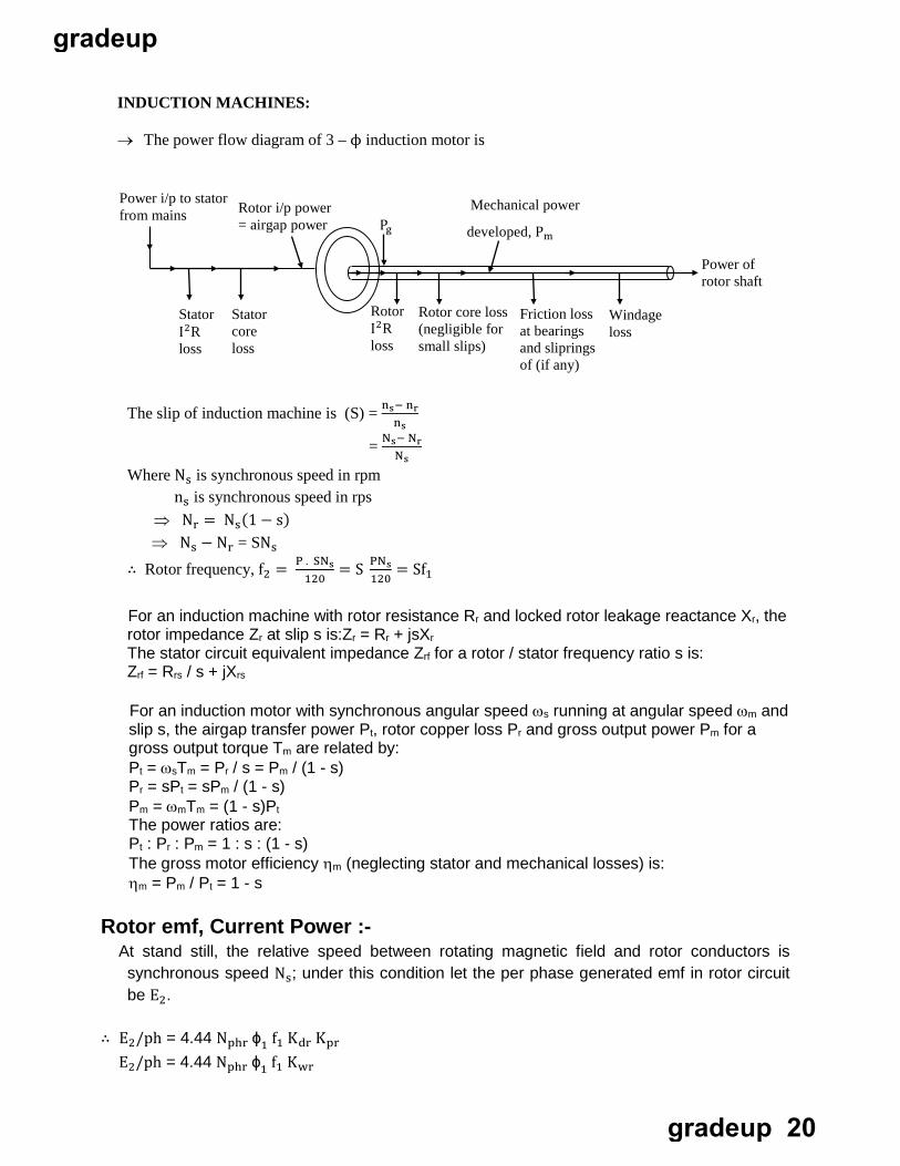
→ The power flow diagram of 3 – ϕ induction motor is
nsThe slip of induction machine is (S) = ns− nr
= Ns− Nr Ns
Where Ns is synchronous speed in rpm ns is synchronous speed in rps ⇒ Nr = Ns(1 − s)⇒ Ns − Nr = SNs
∴ Rotor frequency, f2 = P . SNs120
= S PNs120
= Sf1
For an induction machine with rotor resistance Rr and locked rotor leakage reactance Xr, the rotor impedance Zr at slip s is:Zr = Rr + jsXr The stator circuit equivalent impedance Zrf for a rotor / stator frequency ratio s is: Zrf = Rrs / s + jXrs
Rotor emf, Current Power :- At stand still, the relative speed between rotating magnetic field and rotor conductors is
synchronous speed Ns; under this condition let the per phase generated emf in rotor circuit be E2.
∴ E2/ph = 4.44 Nphr ϕ1 f1 Kdr Kpr E2/ph = 4.44 Nphr ϕ1 f1 Kwr
Mechanical power
developed, Pm Pg Rotor i/p power = airgap power
Power i/p to stator from mains
Power of rotor shaft
Windage loss
Friction loss at bearings and sliprings of (if any)
Rotor core loss (negligible for small slips)
Rotor I2R loss
Stator core loss
Stator I2R loss
For an induction motor with synchronous angular speed ωs running at angular speed ωm and slip s, the airgap transfer power Pt, rotor copper loss Pr and gross output power Pm for a gross output torque Tm are related by: Pt = ωsTm = Pr / s = Pm / (1 - s) Pr = sPt = sPm / (1 - s) Pm = ωmTm = (1 - s)Pt The power ratios are: Pt : Pr : Pm = 1 : s : (1 - s) The gross motor efficiency ηm (neglecting stator and mechanical losses) is: ηm = Pm / Pt = 1 - s
gradeup
gradeup 20
Kwr = Rotor winding factor
→ But during running conditions the frequency of the rotor becomes, running with speed Nr
P(Ns− Nr)120
= P SNs120
= Sf1 ∴ fr = Sf1 ∴ Emf under running conditions is
E = √2 π fr Kw2 Nphr ϕ1 = SE2
→ Rotor leakage reactance = 2π (Rotor frequency) (Rotor leakage Inductance)
∴ Rotor leakage reactance at stand still = 2π f1𝑙𝑙2 = x2 Ω
→ Rotor leakage reactance at any slips = 2π f2𝑙𝑙2
→ Rotor leakage impedance at stand still
= �r 2 2 + x2
2
→ At any slip s, rotor
= �r
2 2+ x2
2
→ Per phase rotor current at any slip s is given by
I2 =SE
�r 2 2 +
2
(sx2)2=
E2
�(r1/s)2 + x 2 2
→ The rotor current I2 lags the rotor voltage E2 by rotor power factor angle θ2 given by θ2 = tan−1 sx2
r2
= sx2 Ω
= �r
2 2 + (sx2)2
→ Per phase rotor current at stand still
E
gradeup
gradeup 21
→ Perr phase power input to rotor is
Pg = F2 I2 cos θ2
cos θ2 = Per phase rotor resistancePer phase rotor impedance
= r2/s�(r2/s)2+ (x2)2
r2/s�(r2/s)2+ (x2)2∴ Pg = E2 I2 ×
` = E2
�(r2/s)2+ (x2)2 × I2 r2s
= I 2 2 r2
s→ Pg is the power transferred from stator to rotor across the air gap. There fore Pg is called air
gap power Pg = I
2 2 r2
s
= I 2 2 r2 + I
2 2 r2 �1−S
S�
Pg = (Rotor ohmic loss) + Internal mechanical power developed in rotor (Pm) = S Pg + (1 − S)Pg
∴ Pm = (1 − S) Pg = I 2 2 r2 �1−S
S�
Rotor ohmic loss = � S1−S
� Pm = SPg
→ Internal (or gross) torque developed per phase is given by
Te = Internal mechanical power developed inrotorRotor speed in mechanical radian per sec
→ Electromagnetic torque Te can also be expressed as
ωs
1ωs
Te = Pg = × I 2 2 r2S (ωs) slip
= Rotor ohmic loss
∴ Te = Rotor ohmic loss(ωs) slip
Te = Pmωr
= (1−S)Pg(1−S)ωs ωs
= Pg
gradeup
gradeup 22
→ Power available at the shaft can be obtained from Pg as follows. Output or shaft power, Psh = Pm − Mechanical losses
→ Mechanical losses implies frication and windage losses
Psh = Pg − Rotor ohmic loss – Friction and windage losses = Net mechanical power output or net power output Output or shaft torque Tsh = Psh = Psh
Rotor speed (1−s) ωs
→ If the stator input is known. Then air gap power Pg is given by Pg = stator power input – stator I2 R loss – stator core loss.
→ Ratio of Rotor input power, rotor copper losses and gross mechanical output is
SRotor copper losses = (Gross Mechanical output) × 1−S
Efficiency of the rotor is approximately Equal to ηrotor = Gross mechanical power output
Rotor input
= (1−S) Rotor input
NS
Rotor input
= 1 – S = 1 − NS− N
Ns = N
Total torque is
Te = mωs
× V e 2
�Re+ rs2�
2+ (x2+ Xe)2
× r2s
Nm
m is the number of stator phases. Torque equation can be written as
Te = mωs
× I 2 2 × r2
s
Te = mωs
× rotor input per phase.
ηrotor ≃ NNs
I r 2 R2/s : Ir
2 R2 : I r 2R2 �1
s− 1�
⇒ 1 : S : (1 – S) ∴ Rotor copper losses = S × Rotor input Gross mechanical output =(1 – S) × Rotor input.
gradeup
gradeup 23
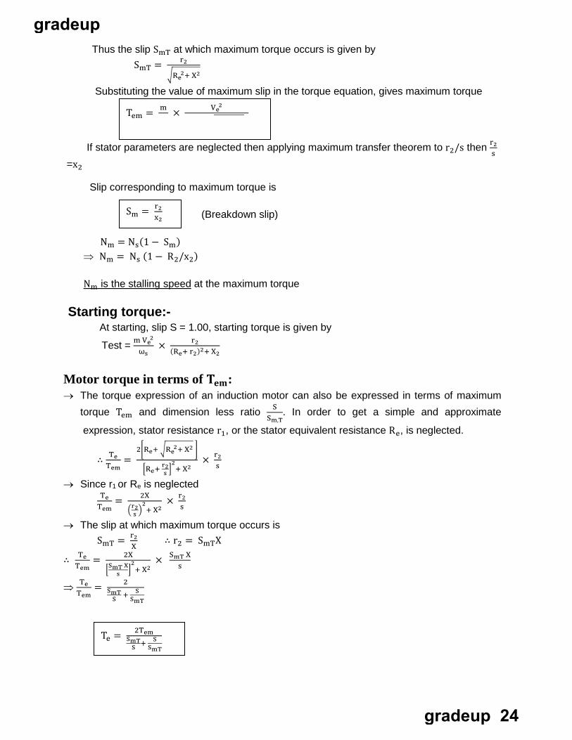
Thus the slip SmT at which maximum torque occurs is given by SmT = r2
�R e 2+ X2
Substituting the value of maximum slip in the torque equation, gives maximum torque
ωs 2�Re+ �R e 2+ X
2 2 �
If stator parameters are neglected then applying maximum transfer theorem to r2/s then r2s
=x2
Slip corresponding to maximum torque is
(Breakdown slip)
Nm = Ns(1 − Sm) ⇒ Nm = Ns (1 − R2/x2)
Nm is the stalling speed at the maximum torque
Tem = m × V e 2
Sm = r2x2
Starting torque:- At starting, slip S = 1.00, starting torque is given by
ωsTest = m V
e 2
× r2(Re+ r2)2+ X2
Motor torque in terms of 𝐓𝐓𝐞𝐞𝐞𝐞: → The torque expression of an induction motor can also be expressed in terms of maximum
torque Tem and dimension less ratio SSm,T
. In order to get a simple and approximate
∴ TeTem
= 2�Re+ �R
e 2+ X2 �
�Re+ rs2�
2+ X2 s
× r2
→ Since r1 or Re is neglected
Tem
2X
�r2s �
2+ X2 s
Te = × r2
→ The slip at which maximum torque occurs is SmT = r2
X
∴ TeTem
= 2X
�SmT Xs �
2+ X2
s
∴ r2 = SmTX
× SmT X
⇒ TeTem
= 2SmT
S + SSmT
expression, stator resistance r1, or the stator equivalent resistance Re, is neglected.
Te = 2TemSmT
S + SSmT
gradeup
gradeup 24
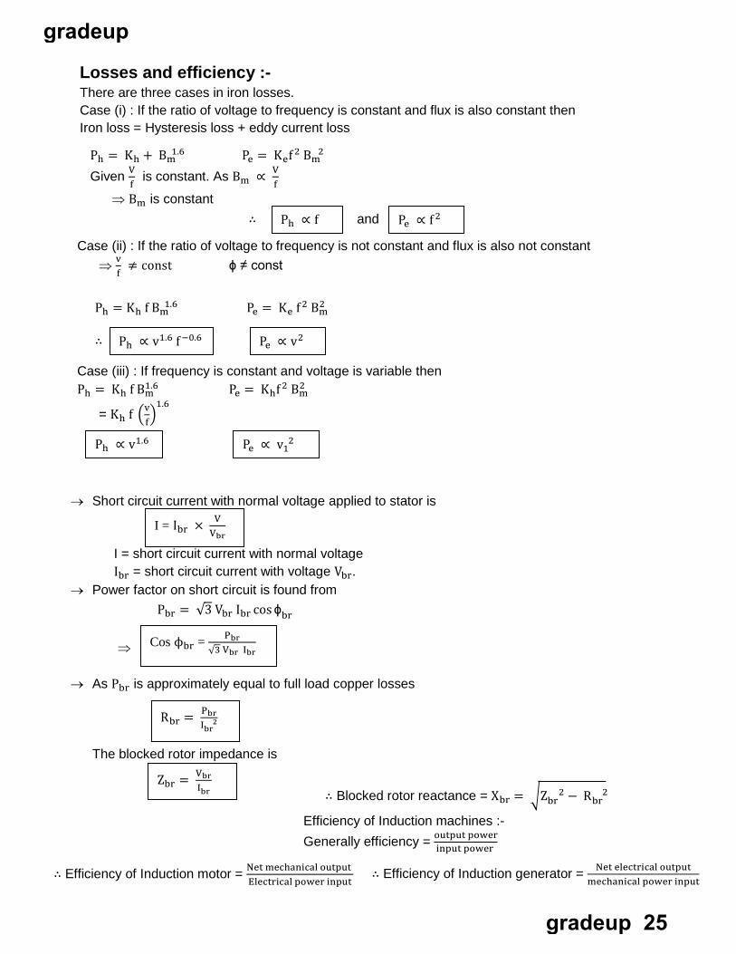
Ph = Kh + B m
1.6 Pe = Kef 2 B m
2
fGiven V is constant. As Bm ∝ V
f⇒ Bm is constant
∴ and
Case (ii) : If the ratio of voltage to frequency is not constant and flux is also not constant
fv⇒ ≠ const ϕ ≠ const
Ph ∝ f Pe ∝ f 2
Ph = Kh f B m
1.6 2Pe = Ke f 2 Bm
1 2Case (iii) : If frequency is constant and voltage is variable then Ph = Kh f Bm
.6 Pe = Khf 2 Bm
f= Kh f �v�
1.6
∴ Ph ∝ v1.6 f −0.6 Pe ∝ v2
Ph ∝ v1.6 Pe ∝ v 1 2
→ Short circuit current with normal voltage applied to stator is
I = short circuit current with normal voltage Ibr = short circuit current with voltage Vbr.
→ Power factor on short circuit is found from Pbr = √3 Vbr Ibr cos ϕbr
⇒
→ As Pbr is approximately equal to full load copper losses
input power
Electrical power input∴ Efficiency of Induction motor = Net mechanical output ∴ Efficiency of Induction generator = Net electrical output
mechanical power input
VI = Ibr × Vbr
Cos ϕbr = Pbr
√3 Vbr Ibr
Rbr = PbrI
b r 2
The blocked rotor impedance is
Zbr = VbrI
br
Losses and efficiency :- There are three cases in iron losses. Case (i) : If the ratio of voltage to frequency is constant and flux is also constant then Iron loss = Hysteresis loss + eddy current loss
∴ Blocked rotor reactance = Xbr = �Z br
2 − R br
2
Efficiency of Induction machines :- Generally efficiency = output power
gradeup
gradeup 25
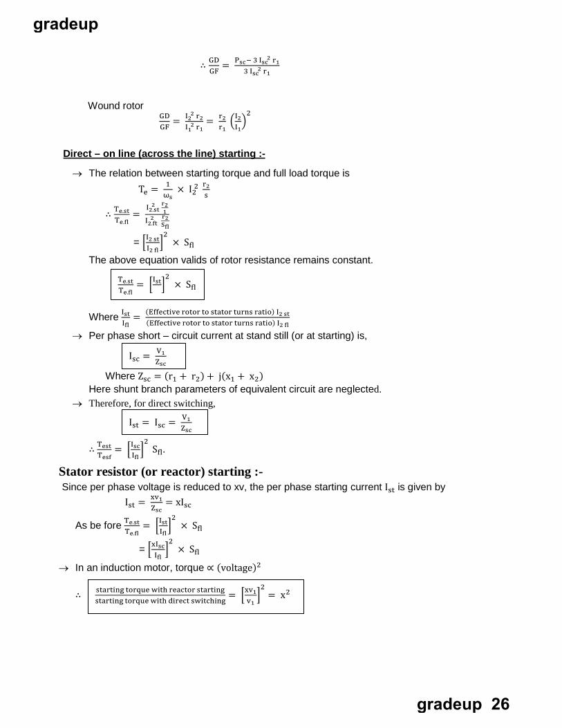
GF∴ GD = Psc− 3 I
sc 2 r1
3 I sc
2 r1
Wound rotor
GFGD = I
2 2 r2
I 1 2 r1
= r2r1
�I2I1
�2
Direct – on line (across the line) starting :-
→ The relation between starting torque and full load torque is Te = 1
ωs× I
22 r2
s
∴ Te.stTe.fl
= I
2 .st2 r2
1I
2 .ft2 r2
Sfl
= �I2 stI2 fl
�2
× Sfl
The above equation valids of rotor resistance remains constant.
Where IstIfl (Effective rotor to stator turns ratio) I2 fl
Ifl
= (Effective rotor to stator turns ratio) I2 st
→ Per phase short – circuit current at stand still (or at starting) is,
Where Zsc = (r1 + r2) + j(x1 + x2) Here shunt branch parameters of equivalent circuit are neglected.
→ Therefore, for direct switching,
∴ TestTesf
= �IscIfl
�2
Sfl.
Stator resistor (or reactor) starting :- Since per phase voltage is reduced to xv, the per phase starting current Ist is given by
Ist = xv1Zsc
= xIsc
As be fore Te.stTe.fl
= �IstIfl
�2
× Sfl
= �xIscIfl
�2
× Sfl
→ In an induction motor, torque ∝ (voltage)2
∴
Te.stTe.fl
= �Ist�2
× Sfl
Isc = V1Zsc
Ist = Isc = V1Zsc
starting torque with reactor startingstarting torque with direct switching
= �xv1v1
�2
= x2
gradeup
gradeup 26
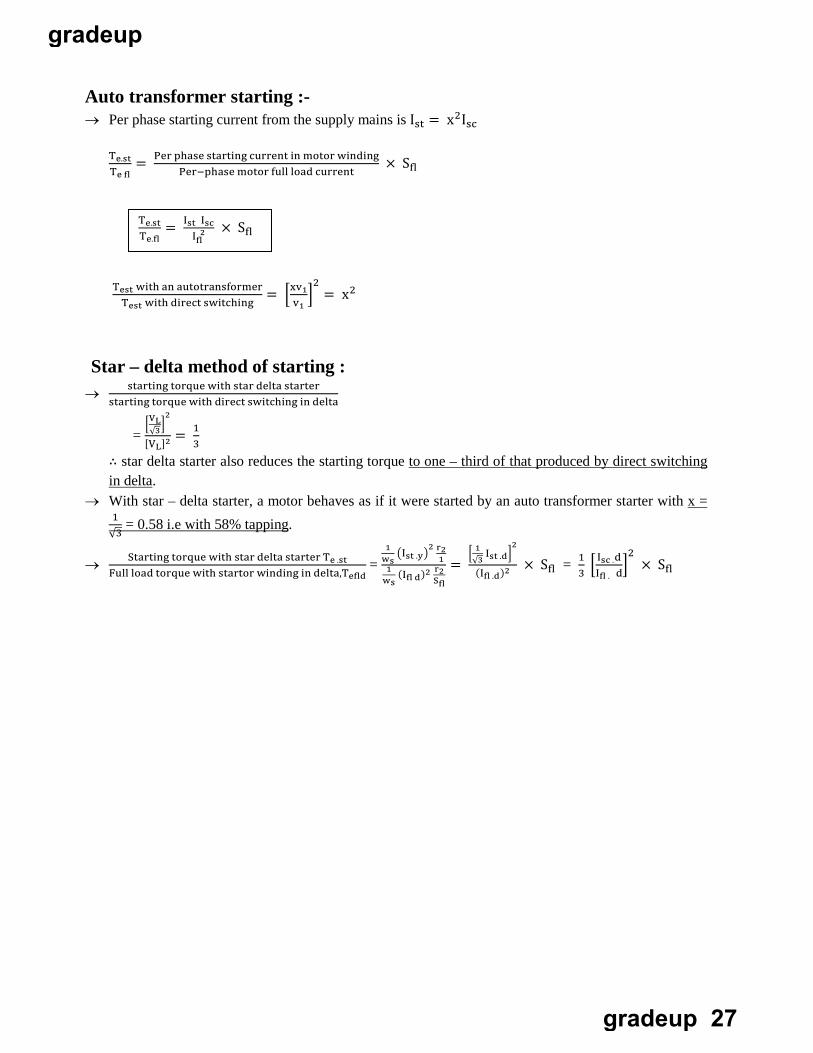
Auto transformer starting :- → Per phase starting current from the supply mains is Ist = x2Isc
Te.stTe fl
= Per phase starting current in motor windingPer−phase motor full load current
× Sfl
Test with an autotransformerTest with direct switching
= �xv1v1
�2
= x2
Star – delta method of starting : → starting torque with star delta starter
starting torque with direct switching in delta
= �VL
√3�2
[VL]2 3= 1
∴ star delta starter also reduces the starting torque to one – third of that produced by direct switching in delta.
→ With star – delta starter, a motor behaves as if it were started by an auto transformer starter with x = 1
√3 = 0.58 i.e with 58% tapping.
→ Starting torque with star delta starter Te .stFull load torque with startor winding in delta,Tefld
= 1
ws�Ist .y�
2 r21
1ws
(Ifl d)2 Sr2
fl
= � 1
√3 Ist .d�2
(Ifl .d)2 × Sfl = 13
� Isc .dIfl . d
�2
× Sfl
Te.stTe.fl
= IstI 2Isc
fl × Sfl
gradeup
gradeup 27