Graded Dielectric Inhomogeneous Planar Layer Radome for ... · Graded Dielectric Inhomogeneous...
14
Copyright © 2014 Tech Science Press CMC, vol.40, no.2, pp.131-143, 2014 Graded Dielectric Inhomogeneous Planar Layer Radome for Aerospace Applications Raveendranath U. Nair, Preethi D.S, and R. M. Jha Abstract: Controllable artificial dielectrics are used in the design of radomes to enhance their electromagnetic (EM) performance. The fabrication of such radome wall structures with controllable dielectric parameters seems to be an arduous task. Further even minor fluctuations of dielectric properties of radome wall due to fab- rication uncertainties tend to result in drastic degradation of radome performance parameters. In the present work, a novel inhomogeneous radome with graded varia- tion of dielectric parameters is proposed which limits the constraints on fabrication and facilitates excellent EM performance characteristics. This radome wall consists of five dielectric layers cascaded such that the middle layer has maximum dielectric constant and electric loss tangent. The dielectric parameters of the layers on both sides of the middle layer decrease in a graded (or step-wise) manner. The EM per- formance characteristics of the IPL radome with graded dielectric parameters are superior to that of conventional monolithic half-wave radome. Keywords: Inhomogeneous planar dielectric radome, Equivalent transmission line model, EM performance parameters. 1 Introduction Several techniques for broadbanding of radomes based on metallic wire grids/ meshes, resonant/ semi-resonant inclusions, anisotropic materials are reported in the open literature [Walton (1966); Bodnar and Basset (1975); Cary (1983); Koza- koff (2010)]. Due to superior filter (band-pass/ band-stop) characteristics, both conventional and metamaterial based frequency selective surfaces are widely used in the design of radomes [Cory et al. (2007); Basiry et al. (2011); Costa and Monorchio (2012), Narayan et al. (2012); Nair et al. (2013)]. Further, materi- als/ structures with controllable dielectric properties have been used in the design of radome wall configurations to meet the high-end electromagnetic (EM) perfor- mance requirements of modern radar antenna systems [Chen et al. (2010); Pei et al. (2012)]. The practical realization of radome wall configurations with control-
Transcript of Graded Dielectric Inhomogeneous Planar Layer Radome for ... · Graded Dielectric Inhomogeneous...

Copyright © 2014 Tech Science Press CMC, vol.40, no.2, pp.131-143, 2014
Graded Dielectric Inhomogeneous Planar Layer Radomefor Aerospace Applications
Raveendranath U. Nair, Preethi D.S, and R. M. Jha
Abstract: Controllable artificial dielectrics are used in the design of radomes toenhance their electromagnetic (EM) performance. The fabrication of such radomewall structures with controllable dielectric parameters seems to be an arduous task.Further even minor fluctuations of dielectric properties of radome wall due to fab-rication uncertainties tend to result in drastic degradation of radome performanceparameters. In the present work, a novel inhomogeneous radome with graded varia-tion of dielectric parameters is proposed which limits the constraints on fabricationand facilitates excellent EM performance characteristics. This radome wall consistsof five dielectric layers cascaded such that the middle layer has maximum dielectricconstant and electric loss tangent. The dielectric parameters of the layers on bothsides of the middle layer decrease in a graded (or step-wise) manner. The EM per-formance characteristics of the IPL radome with graded dielectric parameters aresuperior to that of conventional monolithic half-wave radome.
Keywords: Inhomogeneous planar dielectric radome, Equivalent transmissionline model, EM performance parameters.
1 Introduction
Several techniques for broadbanding of radomes based on metallic wire grids/meshes, resonant/ semi-resonant inclusions, anisotropic materials are reported inthe open literature [Walton (1966); Bodnar and Basset (1975); Cary (1983); Koza-koff (2010)]. Due to superior filter (band-pass/ band-stop) characteristics, bothconventional and metamaterial based frequency selective surfaces are widely usedin the design of radomes [Cory et al. (2007); Basiry et al. (2011); Costa andMonorchio (2012), Narayan et al. (2012); Nair et al. (2013)]. Further, materi-als/ structures with controllable dielectric properties have been used in the designof radome wall configurations to meet the high-end electromagnetic (EM) perfor-mance requirements of modern radar antenna systems [Chen et al. (2010); Pei etal. (2012)]. The practical realization of radome wall configurations with control-

132 Copyright © 2014 Tech Science Press CMC, vol.40, no.2, pp.131-143, 2014
lable dielectric characteristics is often a challenging problem [Nair et al. (2012)].In the present work, inhomogeneous planar layer (IPL) radome wall configurationwith graded dielectric parameters is proposed, which can be easily fabricated bycascading different dielectric layers (Fig.1). Here the dielectric parameters are in-creased from the outer wall to the middle layer in a graded manner (or step-wisevariation). The EM performance analysis indicates that the graded dielectric IPLradome wall configuration has superior EM performance parameters as comparedto that of conventional monolithic half-wave radome of identical thickness.
(a)
(b)
0 d
2d
Graded IPL Radome
(Mid-plane)
rm = 4.0
r = 1.15
r = 1.04
tan em = 0.015
tan e = 0.0008
tan e = 0.002
Glass epoxy (layer 3)
Honeycomb (layer 1)
Foam (layer 2)
Foam (layer 4)
Honeycomb (layer 5)
Figure 1: (a) Schematic of graded dielectric IPL radome and (b) Graded variationof dielectric parameters across the radome wall.
2 Graded Dielectric IPL Radome: EM Design Aspects
The radome wall consists of five cascaded dielectric layers with different dielec-tric properties (Fig. 1a). The total thickness of the entire radome wall is 7.44 m-

Graded Dielectric Inhomogeneous Planar Layer Radome 133
m, which is the optimized thickness of conventional monolithic half-wave radome(design frequency of 10 GHz). Both Layer 1 and Layer 5 are made of quartz hon-eycomb (dielectric constant, εr = 1.04; and loss tangent, tan δ e = 0.0008). Layer 2and Layer 4 are made of polyurethane foam (εr = 1.15 and tan δ e = 0.002). Layer3 (central layer) is made of glass epoxy having the highest dielectric parameters(εrm = 4.0 and tan δ em = 0.015). Thus graded (or step-like) variation of dielectricparameters is incorporated in the radome wall (Fig. 1b).
Table 1: Optimized design parameters of graded IPL radome (Polarization: per-pendicular).
Layer Material Thickness(mm)
DielectricConstant
Loss tangent
Layer 1 Quartz Honeycomb 2 1.04 0.0008Layer 2 PU Foam 1.57 1.15 0.002Layer 3 Glass Epoxy 0.3 4.0 0.015Layer 4 PU Faom 1.57 1.15 0.002Layer 5 Quartz Honeycomb 2 1.04 0.0008
Z1 Z2 Z4
Z0
Z4 Z2 Z1
Source
Z3
Z3 Z5
Z5
Figure 2: Equivalent transmission line model of graded dielectric IPL radome.
The graded dielectric IPL radome is modeled as an equivalent transmission linewith different sections corresponding to respective dielectric layers (Fig. 2). Theradome performance parameters are computed using equivalent transmission linemodel [Nair et al. (2012)]. The voltage-current transmission matrix of the entiregraded dielectric IPL radome wall is obtained as,

134 Copyright © 2014 Tech Science Press CMC, vol.40, no.2, pp.131-143, 2014
[A BC D
]=
[cosϕ1 j Z1
Z0sinϕ1
j Z1Z0
sinϕ1 cosϕ1
][cosϕ2 j Z2
Z0sinϕ2
j Z2Z0
sinϕ2 cosϕ2
] [cosϕ3 j Z3
Z0sinϕ3
j Z3Z0
sinϕ3 cosϕ3
][
cosϕ4 j Z4Z0
sinϕ4
j Z4Z0
sinϕ4 cosϕ4
][cosϕ5 j Z5
Z0sinϕ5
j Z5Z0
sinϕ5 cosϕ5
](1)
Here Z1, Z2, Z3, Z4, and Z5 are the intrinsic impedances of the layers. Z0 is thefreespace impedance. The electrical length φ of each layer is a function of thethickness, complex permittivity, angle of incidence, and wavelength of incidentwave.
The power transmission is expressed as
Ptr =
∣∣∣∣( 2A+B+C+D
)∣∣∣∣2 (2)
Similarly, the power reflection is given by
Pr f =
∣∣∣∣(A+B−C−DA+B+C+D
)∣∣∣∣2 (3)
The insertion phase delay (IPD) of the graded dielectric IPL radome is given by
IPD =− (∠T1 +∠T2 +∠T3 +∠T4 +∠T5)
− 2π
λ(d1 cosθ1 +d2 cosθ2 +d3 cosθ3 +d4 cosθ4 +d5 cosθ5)
(4)
Here ∠T1, . . . , ∠T5 are the phase angles associated with the voltage transmis-sion coefficients of the dielectric layers with thicknesses d1, . . . ,d5 respectively.θ 1,. . . ,θ 5 are the corresponding incidence angles at the interfaces of the dielectriclayers.
3 EM Performance Analysis
The EM performance envelopes corresponding to power transmission, power re-flection, and IPD characteristics of graded dielectric IPL radome, and monolithichalf-wave radome of identical thickness over the entire range of incidence anglesfrom 0˚ to 80˚ and X-band are shown in Figures 3 through 5. Since the EM perfor-mance degradation for perpendicular polarization represents the worst-case scenari-o, the EM performance parameters are analyzed only for perpendicular polarizationin the present work.

Graded Dielectric Inhomogeneous Planar Layer Radome 135
40
60
80
100
8
9
10
11
12
20
40
60
80
Pow
er T
rans
mis
sion
(%
)
Frequen
cy (G
Hz)
Angle of Incidence (Deg)
Figure 3: Power Transmission characteristics of graded IPL radome over a widerange of incidence angles and X-band (Polarization: perpendicular).
0
20
40
60
80
100
8
9
10
11
12
20
40
60
80
Pow
er R
efle
ctio
n (%
)
Frequen
cy (G
Hz)
Angle of Incidemce (Deg)
Figure 4: Power reflection characteristics of graded IPL radome over a wide rangeof incidence angles and X-band (Polarization: perpendicular).
0
20
40
60
80
100
8
9
10
11
12
20
40
60
80
IPD
(D
eg)
Frequen
cy (G
Hz)
Angle of Incidence (Deg)
Figure 5: Insertion phase delay characteristics of graded IPL radome over a widerange of incidence angles and X-band (Polarization: perpendicular).
136 Copyright © 2014 Tech Science Press CMC, vol.40, no.2, pp.131-143, 2014
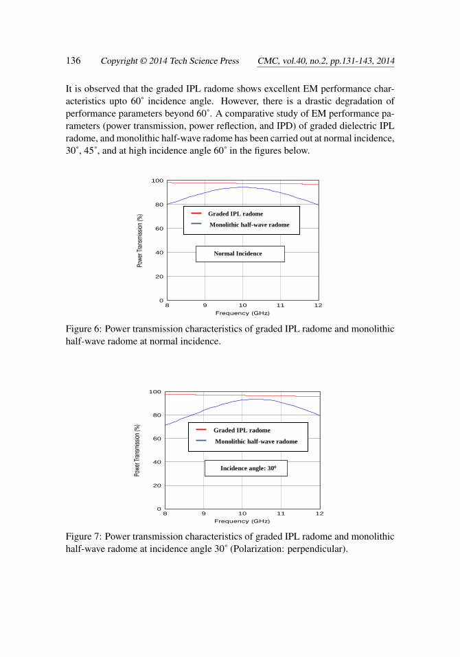
It is observed that the graded IPL radome shows excellent EM performance char-acteristics upto 60˚ incidence angle. However, there is a drastic degradation ofperformance parameters beyond 60˚. A comparative study of EM performance pa-rameters (power transmission, power reflection, and IPD) of graded dielectric IPLradome, and monolithic half-wave radome has been carried out at normal incidence,30˚, 45˚, and at high incidence angle 60˚ in the figures below.
8 9 10 11 120
20
40
60
80
100
Normal Incidence
Graded IPL radome
Monolithic half-wave radome
Figure 6: Power transmission characteristics of graded IPL radome and monolithichalf-wave radome at normal incidence.
8 9 10 11 120
20
40
60
80
100
Incidence angle: 30
Graded IPL radome
Monolithic half-wave radome
Figure 7: Power transmission characteristics of graded IPL radome and monolithichalf-wave radome at incidence angle 30˚ (Polarization: perpendicular).
Graded Dielectric Inhomogeneous Planar Layer Radome 137
8 9 10 11 120
20
40
60
80
100
Incidence angle: 45
Graded IPL radome
Monolithic half-wave radome
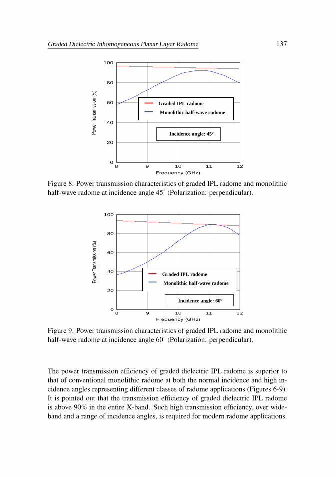
Figure 8: Power transmission characteristics of graded IPL radome and monolithichalf-wave radome at incidence angle 45˚ (Polarization: perpendicular).
8 9 10 11 120
20
40
60
80
100
Incidence angle: 60
Graded IPL radome
Monolithic half-wave radome
Figure 9: Power transmission characteristics of graded IPL radome and monolithichalf-wave radome at incidence angle 60˚ (Polarization: perpendicular).
The power transmission efficiency of graded dielectric IPL radome is superior tothat of conventional monolithic radome at both the normal incidence and high in-cidence angles representing different classes of radome applications (Figures 6-9).It is pointed out that the transmission efficiency of graded dielectric IPL radomeis above 90% in the entire X-band. Such high transmission efficiency, over wide-band and a range of incidence angles, is required for modern radome applications.

138 Copyright © 2014 Tech Science Press CMC, vol.40, no.2, pp.131-143, 2014
Low power reflection characteristic is achieved for the graded IPL radome design atboth normal incidence, and high incidence angles over the entire X-band frequencyregime (Figures 10-13).
8 9 10 11 120
10
20
30
40
50
60
70
Normal Incidence
Graded IPL radome
Monolithic half-wave radome
Figure 10: Power reflection characteristics of graded IPL radome and monolithichalf-wave radome at normal incidence.
8 9 10 11 12
Frequency (GHz)
0
10
20
30
40
50
60
70
Pow
er R
efle
ctio
n(%
)
Incidence angle: 30
Graded IPL radome
Monolithic half-wave radome
Figure 11: Power reflection characteristics of graded IPL radome and monolithichalf-wave radome at incidence angle 30˚ (Polarization: perpendicular).

Graded Dielectric Inhomogeneous Planar Layer Radome 139
8 9 10 11 12
Frequency (GHz)
0
10
20
30
40
50
60
70
Pow
er R
efle
ctio
n(%
) Incidence angle: 45
Graded IPL radome
Monolithic half-wave radome
Figure 12: Power reflection characteristics of graded IPL radome and monolithichalf-wave radome at incidence angle 45˚ (Polarization: perpendicular).
8 9 10 11 120
10
20
30
40
50
60
70
Incidence angle: 60
Graded IPL radome
Monolithic half-wave radome
Figure 13: Power reflection characteristics of graded IPL radome and monolithichalf-wave radome at incidence angle 60˚ (Polarization: perpendicular).
Such low power reflection characteristics are desirable for radome applications asit facilitates the reduction of sidelobe level (SLL) degradations of antenna radia-tion pattern, minimization of pattern ripples, and elimination of flash lobes in thescan volume. The variation of IPD for graded dielectric IPL radome over the X-band frequency range is less than that of monolithic radome (Figures 14-17). SuchIPD characteristics (low magnitude and small variation across the entire X-band)

140 Copyright © 2014 Tech Science Press CMC, vol.40, no.2, pp.131-143, 2014
indicate low phase distortions, which in turn reduces the boresight error (BSE) forstreamlined nosecone radomes for airborne applications.
8 9 10 11 120
50
100
150
200
Normal Incidence
Graded IPL radome
Monolithic half-wave radome
Figure 14: Insertion phase delay characteristics of graded IPL radome and mono-lithic half-wave radome at normal incidence.
8 9 10 11 12
Frequency (GHz)
0
50
100
150
200
IPD
(Deg
) Incidence angle: 30
Graded IPL radome
Monolithic half-wave radome
Figure 15: Insertion phase delay characteristics of graded IPL radome and mono-lithic half-wave radome at incidence angle 30˚ (Polarization: perpendicular).

Graded Dielectric Inhomogeneous Planar Layer Radome 141
8 9 10 11 120
50
100
150
200
Incidence angle: 45
Graded IPL radome
Monolithic half-wave radome
Figure 16: Insertion phase delay characteristics of graded IPL radome and mono-lithic half-wave radome at incidence angle 45˚ (Polarization: perpendicular).
8 9 10 11 120
50
100
150
200
Graded IPL radome
Monolithic half-wave radome
Incidence angle: 60
Figure 17: Insertion phase delay characteristics of graded IPL radome and mono-lithic half-wave radome at 60˚ (Polarization: perpendicular).
4 Conclusion
The present work shows that the graded IPL radome has superior EM performancecharacteristics at both the normal and high incidence angles, as compared to theconventional monolithic radome. This establishes that the graded IPL radome wall
142 Copyright © 2014 Tech Science Press CMC, vol.40, no.2, pp.131-143, 2014
configuration has promising application in the design of hemispherical, cylindricalradomes and streamlined nosecone radomes. Since this structure offers superiorpower transmission and low IPD characteristics, it has also potential applicationin the design of walls for structurally integrated radiating systems for aircraft andcoverings for embedded antennas in aircraft wing and fuselage.
References
Basiry, R.; Abiri, H.; Yahaghi, A. (2011): Electromagnetic performance analysisof omega type metamaterial radome. International Journal of RF and MicrowaveComputer-Aided Engineering, vol. 21, no. 6, pp. 665-673.
Bodnar, D. G.; Basset, H. L. (1975): Analysis of an anisotropic dielectric radome.IEEE Transactions on Antennas and Propagation, vol. 23, pp. 841-846.
Cary, R. H. J. (1983): Radomes, The Handbook of Antenna Design. Peter Pere-grinus, London, ISBN 0-906048-87-7, p. 930.
Chen, F.; Shen, Q.; Zhang, L. (2010): Electromagnetic optimal design and prepa-ration of broadband ceramic radome material with graded porous structure. Progressin Electromagnetics Research, vol. 105, pp. 445-461.
Cory, S.; Lee, Y. J.; Hao, Y.; Parini, C. G. (2007): Use of conjugate dielectricand metamaterial slabs as radomes. IET Microwaves, Antennas, and Propagation,vol. 1, no. 1, pp. 137-143.
Costa, F.; Monorchio, A. (2012): A frequency selective radome with widebandabsorbing properties. IEEE Transactions on Antennas and Propagation, vol. 60,no. 6, pp. 2740-2747.
Kozakoff, D. J. (2010): Analysis of radome enclosed antennas , Artech House,Norwood, USA, ISBN 13: 978-1-59693-441-2, p. 318.
Nair, R. U.; Sandhya, S.; Jha, R. M. (2012): Novel inhomogenous planar layerradome design for airborne applications. IEEE Antennas and Wireless PropagationLetters, vol. 11, no. 1, pp. 854-856.
Nair, R. U.; Jha, R. M. (2013): Broadbanding of A-sandwich radome usingJerusalem cross frequency selective surface. Computers, Materials & Continua,vol. 37, no. 2, pp. 109-121.
Narayan, S.; Shamala, J. B.; Nair, R. U.; Jha, R. M. (2012): Electromagneticperformance analysis of novel multiband metamaterial FSS for millimeter waveradome applications. Computers, Materials & Continua, vol. 31, no. 1, pp. 1-16.
Pei, Y.; Zeng, A.; Zhou, L.; Zhang, R.; Xu, K. (2012): Electromagnetic optimaldesign for dual-band radome wall with alternating layers of staggered compositeand Kagome lattice structure. Progress in Electromagnetics Research, vol. 122,

Graded Dielectric Inhomogeneous Planar Layer Radome 143
pp. 437-452.
Walton J. D. (1966): Techniques for airborne radome design. AFAL Report, no.45433.