GR-150XL - CraneNetwork.com
16
Feet Meters Turning radius 4 wheel steer 12' 5-5/8" 3.8 2 wheel steer 21' 3-7/8" 6.5 Specifications are subject to change without notice. Specifications effective with S/N FD1787 and up. GENERAL DIMENSIONS (275/80R22.5 Tires) GR-150XL 15 Ton Capacity (13.6 Metric Tons) HYDRAULIC ROUGH TERRAIN CRANE DIMENSIONS
Transcript of GR-150XL - CraneNetwork.com
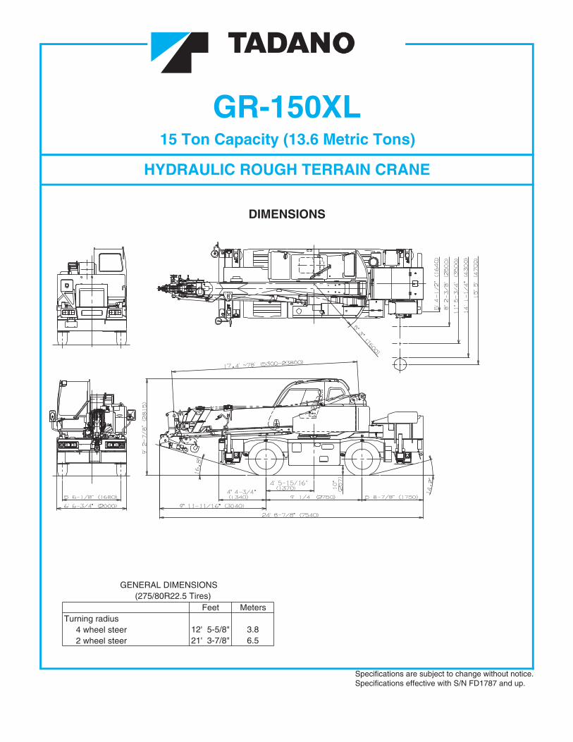
Feet MetersTurning radius 4 wheel steer 12' 5-5/8" 3.8 2 wheel steer 21' 3-7/8" 6.5
Specifications are subject to change without notice.Specifications effective with S/N FD1787 and up.
GENERAL DIMENSIONS (275/80R22.5 Tires)
GR-150XL15 Ton Capacity (13.6 Metric Tons)
HYDRAULIC ROUGH TERRAIN CRANE
DIMENSIONS
1
Six section full power synchronized telescoping boom,
CRANE SPECIFICATIONSBOOM
WIRE ROPE - Warrington seal wire, extra improved plow steel,preformed, independent wire rope core, right regular lay.
17.4'~78' (5.3m~23.8m), of box construction with 4 sheaves,9-5/16" (0.236m) root diameter, at boom head.The synchronization system consists of two double acting
iliary) : 5,730lbs (2,600kg)
telescope cylinders , extension cables and retraction cables. Hydraulic cylinder fitted with holding valve.
HOOK BLOCKS
sections are
.epor eriw )mm2.11("61/7 rof ,hctal ytefas
.yllatnoziroh
dna leviws htiw kooh dethgieW - )not cirtem 8.1( not 0.2
.sdnoces 25 ni )m5.81( '6.06 deeps noisnetxE
safety latch, for 7/16"(11.2mm) wire rope.
BOOM ELEVATION - By a double acting hydraulic cylinder
with holding valve. Elevation -3o~82o, combination controls for
HYDRAULIC SYSTEM
hand or foot operation. Boom angle indicator.Automatic speed reduction and soft stop function.
PUMPS - Two variable piston pumps for crane functions.
Elevation speed -3o~82o
.rotalumucca dna gniws ,gnireets rof pmup raeg mednaT
.sdnoces 92 ni
Powered by carrier engine. Pump disconnect for crane is
JIB(OPTIONAL) - Two stage extension type with 5o, 25o,45o or 60o
engaged/ disengaged by rotary switch from operator's cab.
offset(tilt type). Single sheave, 8"(0.203m) root diameter, at jib head.Box type top section telescopes from box type base section
CONTROL VALVES - Multiple valves actuated by pilot.sevlav feiler erusserp largetni htiw erusserp
.noitces moob esab rednu serots hcihwJib length is 11.8' (3.6m) or 18' (5.5m).
RESERVOIR - 45 gallon (172 lit.) capacity. External sight
AUXILIARY LIFTING SHEAVE (SINGLE TOP) (OPTIONAL)
level gauge.
Single sheave, 8"(0.203m) root diameter. Mounted to mainboom head for single line work.
FILTRATION - (26 micron) return filter, full flow withprotection, located inside of hydraulic reservoir.
ANTI-TWO BLOCK - Pendant type over-winding cut out
easy replacement.
device with audio-visual (FAILURE lamp/BUZZER) warningsystem.
OIL COOLER - Air cooled fan type.
SWINGHydraulic axial piston motor driven through planetary swing
CAB AND CONTROLS
speed reducer. Continuous 360o full circle swing on ball bearingturntable at 2.4rpm. Equipped with manually locked/releasedswing brake. A 360o positive swing lock for pick and carryand travel modes.
Right side, 1 man type, steel construction with sliding door
HOIST
access and tinted safety glass windows opening at side. Doorwindow is powered control. Windshield glass window and roof
MAIN HOIST - Grooved drum driven by hydraulic axial piston
glass window are shatter-resistant. Tilt-telescoping steering
motor through winch speed reducer. Power load lowering andraising. Equipped with automatic brake (neutral brake) and
and main hoist. Control lever can
counterbalance valve. Controlled independently of auxiliary hoist.
change neutral positions and tilt for easy access into cab.
Equipped with cable follower and drum rotation indicator.
armrest. Engine throttle knob. Foot operated controls : boom
DRUM - Grooved 10-7/16"(0.265m) root diameter x 9-7/16"(0.239m)
hoist, boom telescoping, service brake and engine throttle.
wide. Wire rope: 433' of 7/16"diameter rope (132m of 11.2mm).Drum capacity: 486.8' (148.4m) 7 layers. Maximum line pull(available): 6,700lbs. (3,050kg). Maximum line speed: 410FPM
gnireets ,hctiws ekarb gnikrap ,hctiws rotceles evird ,rethgil
.reyal ht5 eht ta )nim/m521(
mode select switch, power window switch, pump engaged /
AUXILIARY HOIST - Grooved drum driven by hydraulic axial
disengaged switch, swing brake switch and outrigger controls.
piston motor through winch speed reducer. Power load loweringand raising. Equipped with automatic brake (neutral brake) andcounterbalance valve. Controlled independently of main hoist.Equipped with cable follower and drum rotation indicator.
on the AML-C display panel.
DRUM - Grooved 10-7/16"(0.265m) root diameter x 9-7/16"(0.239m)wide. Wire rope: 217' of 7/16"diameter rope (66m of 11.2mm).Drum capacity: 486.8' (148.4m) 7 layers. Maximum line pull (available): 6,700lbs. (3,050kg). Maximum line speed: 361FPM (110m/min) at the 3rd layer.
1010 ≥β
2
removable wire rope guards, rope dead end provided on both sides of boom head. 7/16"(11.2mm) 6X37 class
Maximum Permissible Line Pull (Main) : 5,450lbs (2,470kg)Maximum Permissible Line Pull (Aux
15.0 ton (13.6 metric ton) - Weighted hook with swivel and
Both crane and drive operations can be performed from onecab mounted on rotating superstructure.
wheel. Adjustable control lever for swing, boom hoist, boomtelescoping, auxiliary hoist
3 way adjustable operator's seat with high back, headrest and
Hot water cab heater and air conditioning.
Dash-mounted engine start/stop, monitor lamps, cigarette
Instruments - Torque converter oil temperature, engine watertemperature, air pressure, fuel, speedometer, tachometer andhour meter. Hydraulic oil pressure is monitored and displayed
pads both vertically andBoom telescope
Two easily
bypassAccessible for
supported by wear
2
Tadano electronic LOAD MOMENT INDICATOR system(AML-C) including
•pre-warning
• Boom position indicator• Outrigger status indicator•
•indication
•on boom elevation and swing NOTE: Each crane motion speed is based on unladen conditions.
• Working condition register switch• Load radius / boom angle / tip height / swing range
preset function• External warning lamp
CARRIER SPECIFICATIONSlockout device.
rear drive.
FRAME - High tensile steel, all welded mono-box construction
TRANSMISSION - Electronically controlled full automaticTIRES - 275/80R22.5
TRAVEL SPEED - 30.4 mph (49 km/h)
outrigger extension (deployment) is permittedMin. Extension 5' 4-1/2" center to centerMid. Extension 8' 2-3/8" center to centerMid. Extension 11' 5-3/4" center to centerMid. Extension 14' 1-1/4" center to centerMax. Extension 15' 5" center to center
Float size(Diameter) 1' 1-3/4" (0.35m)ENGINEModel Mitsubishi 4M50-TLA3B edllortnoc tatsomreht ,eroc ebut dna niF rotaidaR
seid noitcejni tceriD epyT el id )754( 81 ,edalb-01 ,epyt noitcuS )mm(.ni ,naF a.No. of cylinders lov 42 gnitratS4 t
nuorg evitagen ,metsys tlov 42 gnigrahCedlooc retfa dna degrahc obrut ,elcyc 4 noitsubmoC duoH .pma 08-2 yrettaB0)21 x 411( 427.4 x 884.4)mm(.ni ,ekortS x eroB r
Displacement, cu. in (liters) 299 (4.9) Compressor, air, CFM(l /min) 21.6 CFM (612) at 2,700rpmA pr007,2 ta )921( 271 ssorG )Wk( rewopesroHateherp tlov 42 retaeh telni ri mAir cleaner Dry type, replaceable element Torque, Max. ft-lb (kgm) 390 (54) at 1,600rpmOil filter Full flow with replaceable element Capacity, gal.(liters)Fuel filter Full flow with replaceable element Cooling water 2.9 (11)Fuel tank, gal.(liters) 50 (189), right side of carrier Lubrication 2.1 ~ 2.9 (8 ~ 11)
)981( 05 leuFssap-yb gnitalucricer ,dezirusserp diuqiL gnilooC
within 5' 4-1/2" (1.64 m) overall width with floats. Outrigger jack
crane duty in confined areas. Both symmetrical and Non-symmetrical
floats are attached thus eliminating the need of manually attaching and detaching them. Controls and sight bubble locatedin superstructure cab. Four outrigger extension lengths areprovided with corresponding "RATED LIFTING CAPACITIES" for
4 wheel coordinated and 4 wheel crab .wheel. Four steering modes available: 2 wheel front, 2 wheel rear,
SUSPENSION - Semi-elliptic leaf springs with hydraulic
BRAKE SYSTEMS - Service: Air over hydraulic disc brakes on
OUTRIGGERS - Four hydraulic, beam and jack outriggers.
all 4 wheels. Parking/Emergency: Spring applied-air releasedbrake acting on input shaft of front axle. Auxiliary: Electropneumatic operated exhaust brake.
Vertical jack cylinders equipped with integral holding valve. Eachoutrigger beam and jack is controlled independently from cab.
TADANO AML-C monitors outrigger extended length andautomatically programs the corresponding "RATED LIFTINGCAPACITIES" table.
Operator's left hand console includes transmission gear selectorand sight level bubble. Upper console includes roof washerand wiper switch, emergency outrigger set up key switch, jibequipped / removed select switch and air conditioning control switch.Lower console includes working light switch and boom emergency
AXLE - Front: Full floating type, steering and driving axle with
STEERING- Hydraulic power steering controlled by steering
Rear: Full floating type, steering and driving axle.
driving axle selector. 6 forward and 2 reverse speeds, constantmesh.
3 speeds - high range - 2 wheel drive; 4 wheel drive3 speeds - low range - 4 wheel drive
telescoping switch (2nd-3rd and 4th-top).
Beams extend to 15' 5" (4.7 m) center-line and retract to
Control lever lockout function with audible and visual
TYPE - Rear engine, right hand steering, driving axle 2-wayselected type by manual switch, 4x2 front drive, 4x4 front and
transmission. Torque converter driving full powershift with
Boom angle / boom length / jib offset angle / loadradius / rated lifting capacities / actual loads read outRatio of actual load moment to rated load moment
Automatic Speed Reduction and Soft Stop function
33
•
•••
•
••
•
•
STANDARD EQUIPMENT- Six section full power partially synchronized boom - Mitsubishi 4M50-TL turbo charged after
17.4' ~ 78' (5.3 m~23.8 m) cooled engine(172HP) with exhaust brake- Main hoist with grooved drum and 433' of 7/16" cable. - Electronic controlled automatic transmission- Drum rotation indicator (visual type) b nevirdniam y torque converter- Anti-Two block device (overwind cutout) - 4 X 4 X 4 drive/steer- Tadano electronic load moment indicator system (AML-C) - Hydraulic lockout suspension system- Outrigger extension leng serit 5.22R08/572-rotceted ht- Electronic crane monitoring sy sekarb csiD-mets
- Self centering finger control levers with pilot control- Control pedals for boom elevating and boom telescoping
- Air dryer
- 3 way adjustable cloth suspension seat with armrests, hig
nE-tleb taes dna kcab h
gine over-run alarm
- Tilt-telescoping steeringmrala pu-kcaB-
leehw - Tinted safety g
ih/erusserp lio woL-rosiv nus dna ssal
gh water temp. warning
- Front windshield wiper and washerdevice(visual)
- Roof window wiper and washer- Rear steer centering light
- Power window (cab door)- Air cleaner dust indicator
- Rear view mirrors (right and left side)- Full instrumentation package
- Cigarette ligih etelpmoC-
rethghway light package
il kroW-bac ni naf cirtcelE-
ghtsarots looT-
tam roolf baC-ge compartment
tik noitalfni eriT-bac s'rotarepo ni tcennocsid pmuP-
- Hys cirtcele tlov 42-
relooc lio ciluardystem
- Independently controlled outrigg not 51-
sre(13.6 metric ton) hook with swivel
- Four outrigg not 0.2-
snoitisop noisnetxe re(1.8 metric ton) hook with swivel
- Self-storing outriggniwoT-
sdap reg hooks-Front and rear
- Hot water cab heater and air conditioner
OPTIONAL EQUIPMENT- 11.8' or 18' (3.6 m or 5.5 m) box jib (tilt type) with 5° , 25°,45° or 60° pinned offsets and self storing pins.- Auxiliary lifting sheave (single top) stowable- Auxiliary hoist with grooved drum / 217' of 7/16" cable and drum rotation indicator (visual type).
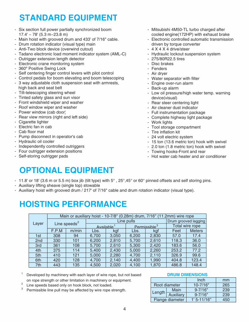
HOISTING PERFORMANCE
F.P.M 1st 308 2nd 330 3rd 361 4th 375 5th 410 6th 420 7th 443
1 Developed by machinery with each layer of wire rope, but not based DRUM DIMENSIONSon rope strength or other limitation in machinery or equipment.
2 Line speeds based only on hook block, not loaded.3 Permissible line pull may be affected by wire rope strength.
450 Flange diameter 1' 5-11/16''
Root diameter
Length
mm265239239
10-7/16"Inch
9-7/16"9-7/16"
148.4
LayerLine pulls Drum grooved lagging
Available1
Main or auxiliary hoist - 10-7/8'' (0.28m) drum, 7/16'' (11.2mm) wire rope
Line speeds2
Total wire ropePermissible3
6,200Meters
4,400
77.2
57.0118.3183.6
123.4
253.299.6
17.436.056.0
m/min Lbs. kgf Lbs. kgf Feet
2,020
6,7006,2005,7005,4005,0004,700
3,0502,8102,6102,4302,2802,140
2,8305,7005,3005,0004,700
2,4202,2602,110
2,610
326.9
486.8404.81,990
1,870
AuxiliaryMain
121128135
94101108114
4,1004,500
4
- 360º Positive Swing Lock - Fenders
- Water separator with filter
4
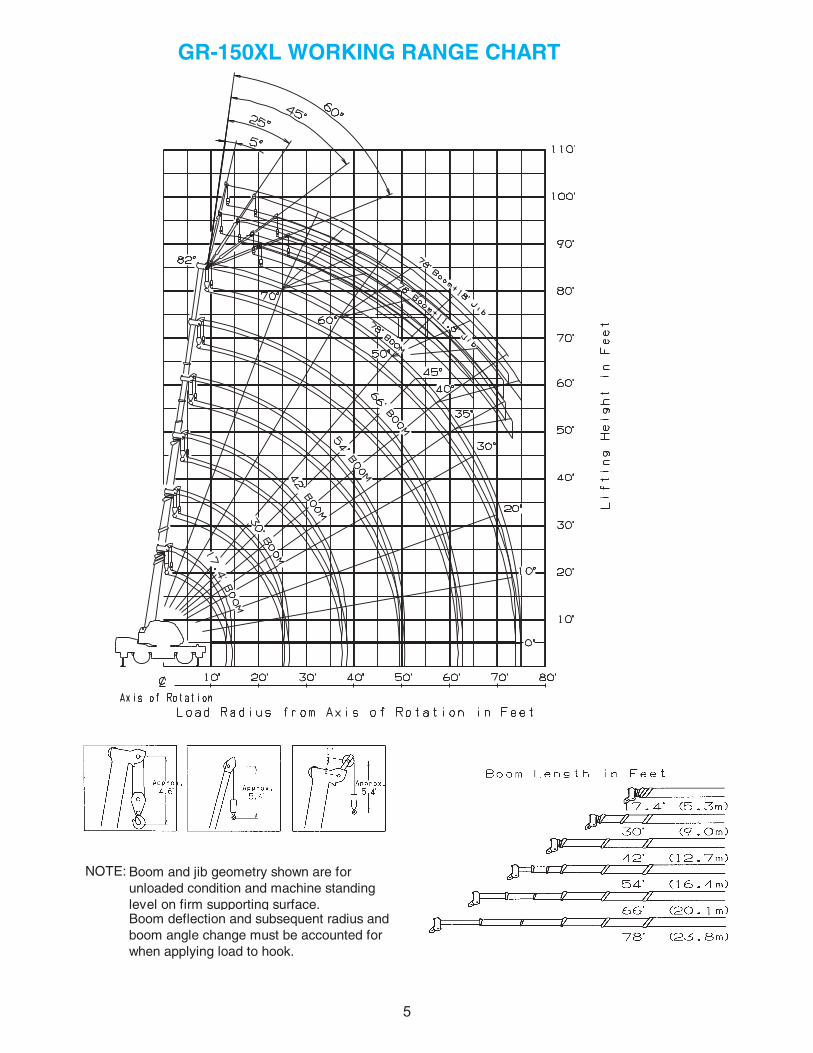
NOTE:
Boom deflection and subsequent radius and boom angle change must be accounted for when applying load to hook.
GR-150XL WORKING RANGE CHART
Boom and jib geometry shown are for unloaded condition and machine standing level on firm supporting surface.
55
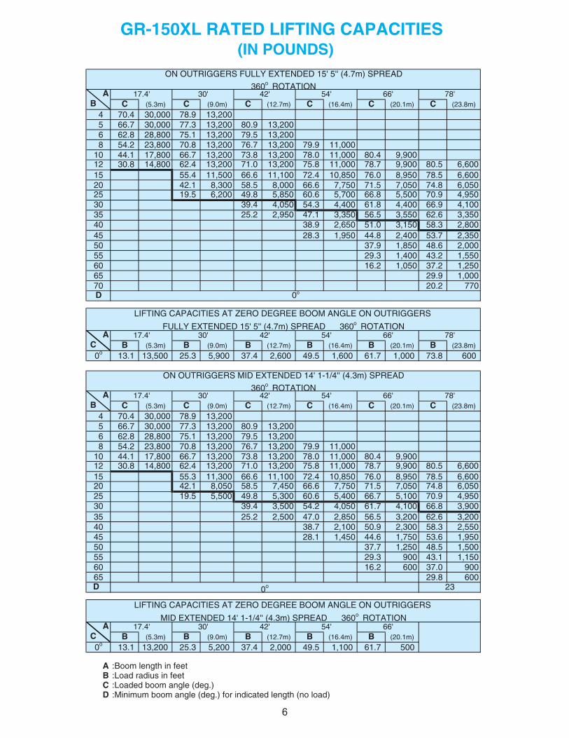
AB C (5.3m) C (9.0m) C (12.7m) C (16.4m) C (20.1m) C (23.8m)
4 70.4 30,000 78.9 13,200 5 66.7 30,000 77.3 13,200 80.9 13,200 6 62.8 28,800 75.1 13,200 79.5 13,200 8 54.2 23,800 70.8 13,200 76.7 13,200 79.9 11,00010 44.1 17,800 66.7 13,200 73.8 13,200 78.0 11,000 80.4 9,90012 30.8 14,800 62.4 13,200 71.0 13,200 75.8 11,000 78.7 9,900 80.5 6,60015 55.4 11,500 66.6 11,100 72.4 10,850 76.0 8,950 78.5 6,60020 42.1 8,300 58.5 8,000 66.6 7,750 71.5 7,050 74.8 6,05025 19.5 6,200 49.8 5,850 60.6 5,700 66.8 5,500 70.9 4,950
001,49.66004,48.16004,43.45050,44.9303053,36.26055,35.65053,31.74059,22.5253008,23.85051,30.15056,29.8304053,27.35004,28.44059,13.8254000,26.84058,19.7305055,12.34004,13.9255052,12.73050,12.6106
65 29.9 1,00070 20.2 770D
AC B (5.3m) B (9.0m) B (12.7m) B (16.4m) B (20.1m) B (23.8m)
0o 13.1 13,500 25.3 5,900 37.4 2,600 49.5 1,600 61.7 1,000 73.8 600
AB C (5.3m) C (9.0m) C (12.7m) C (16.4m) C (20.1m) C (23.8m)
4 70.4 30,000 78.9 13,200 5 66.7 30,000 77.3 13,200 80.9 13,200 6 62.8 28,800 75.1 13,200 79.5 13,200 8 54.2 23,800 70.8 13,200 76.7 13,200 79.9 11,00010 44.1 17,800 66.7 13,200 73.8 13,200 78.0 11,000 80.4 9,90012 30.8 14,800 62.4 13,200 71.0 13,200 75.8 11,000 78.7 9,900 80.5 6,60015 55.3 11,300 66.6 11,100 72.4 10,850 76.0 8,950 78.5 6,60020 42.1 8,050 58.5 7,450 66.6 7,750 71.5 7,050 74.8 6,05025 19.5 5,500 49.8 5,300 60.6 5,400 66.7 5,100 70.9 4,950
009,38.66001,47.16050,42.45005,34.9303002,36.26002,35.65058,20.74005,22.5253055,23.85003,29.05001,27.8304059,16.35057,16.44054,11.8254005,15.84052,17.7305051,11.340093.92550090.730062.6106
65 29.8 600D
AC B (5.3m) B (9.0m) B (12.7m) B (16.4m) B (20.1m)
0o 13.1 13,200 25.3 5,200 37.4 2,000 49.5 1,100 61.7 500
A :Boom length in feetB :Load radius in feetC :Loaded boom angle (deg.)D :Minimum boom angle (deg.) for indicated length (no load)
78'
66'MID EXTENDED 14' 1-1/4'' (4.3m) SPREAD 360o ROTATION
17.4' 30' 42' 54'
ON OUTRIGGERS MID EXTENDED 14' 1-1/4'' (4.3m) SPREAD
360o ROTATION
LIFTING CAPACITIES AT ZERO DEGREE BOOM ANGLE ON OUTRIGGERS
0o 23
17.4' 30' 42' 54' 66'
GR-150XL RATED LIFTING CAPACITIES
17.4' 30' 42' 54' 66'
ON OUTRIGGERS FULLY EXTENDED 15' 5'' (4.7m) SPREAD
78'360o ROTATION
(IN POUNDS)
78'FULLY EXTENDED 15' 5'' (4.7m) SPREAD 360o ROTATION
0o
LIFTING CAPACITIES AT ZERO DEGREE BOOM ANGLE ON OUTRIGGERS
17.4' 30' 42' 54' 66'
66
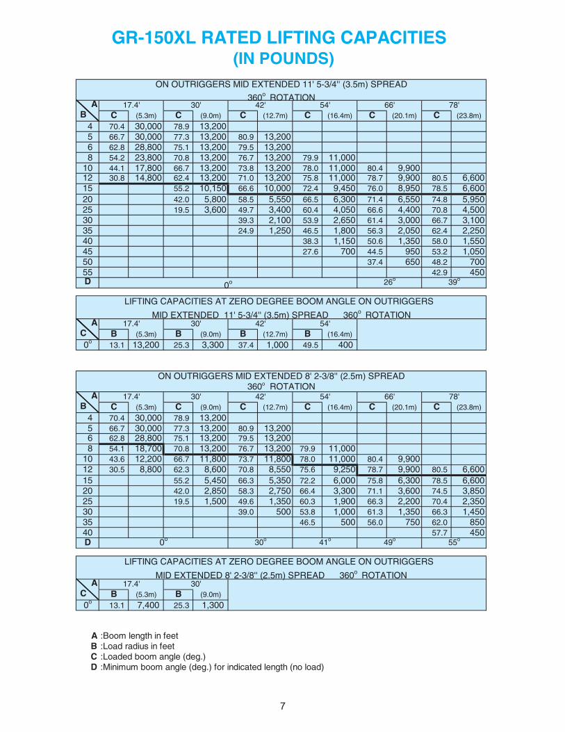
AB C (5.3m) C (9.0m) C (12.7m) C (16.4m) C (20.1m) C (23.8m)
4 70.4 30,000 78.9 13,200 5 66.7 30,000 77.3 13,200 80.9 13,200 6 62.8 28,800 75.1 13,200 79.5 13,200 8 54.2 23,800 70.8 13,200 76.7 13,200 79.9 11,00010 44.1 17,800 66.7 13,200 73.8 13,200 78.0 11,000 80.4 9,90012 30.8 14,800 62.4 13,200 71.0 13,200 75.8 11,000 78.7 9,900 80.5 6,60015 55.2 10,150 66.6 10,000 72.4 9,450 76.0 8,950 78.5 6,60020 42.0 5,800 58.5 5,550 66.5 6,300 71.4 6,550 74.8 5,95025 19.5 3,600 49.7 3,400 60.4 4,050 66.6 4,400 70.8 4,50030 39.3 2,100 53.9 2,650 61.4 3,000 66.7 3,10035 24.9 1,250 46.5 1,800 56.3 2,050 62.4 2,25040 38.3 1,150 50.6 1,350 58.0 1,55045 27.6 700 44.5 950 53.2 1,05050 37.4 650 48.2 70055 42.9 450D
AC B (5.3m) B (9.0m) B (12.7m) B (16.4m)
0o 13.1 13,200 25.3 3,300 37.4 1,000 49.5 400
AB C (5.3m) C (9.0m) C (12.7m) C (16.4m) C (20.1m) C (23.8m)
4 70.4 30,000 78.9 13,200 5 66.7 30,000 77.3 13,200 80.9 13,200 6 62.8 28,800 75.1 13,200 79.5 13,200 8 54.1 18,700 70.8 13,200 76.7 13,200 79.9 11,00010 43.6 12,200 66.7 11,800 73.7 11,800 78.0 11,000 80.4 9,90012 30.5 8,800 62.3 8,600 70.8 8,550 75.6 9,250 78.7 9,900 80.5 6,60015 55.2 5,450 66.3 5,350 72.2 6,000 75.8 6,300 78.5 6,60020 42.0 2,850 58.3 2,750 66.4 3,300 71.1 3,600 74.5 3,85025 19.5 1,500 49.6 1,350 60.3 1,900 66.3 2,200 70.4 2,35030 39.0 500 53.8 1,000 61.3 1,350 66.3 1,45035 46.5 500 56.0 750 62.0 85040 57.7 450D
AC B (5.3m) B (9.0m)
0o 13.1 7,400 25.3 1,300
A :Boom length in feetB :Load radius in feetC :Loaded boom angle (deg.)D :Minimum boom angle (deg.) for indicated length (no load)
41o 55o49o
LIFTING CAPACITIES AT ZERO DEGREE BOOM ANGLE ON OUTRIGGERS
MID EXTENDED 8' 2-3/8'' (2.5m) SPREAD 360o ROTATION
66' 78''45'4.71
0o 30o
42' 54' 66' 78'
17.4' 30'
30' 42'
ON OUTRIGGERS MID EXTENDED 8' 2-3/8'' (2.5m) SPREAD360o ROTATION
GR-150XL RATED LIFTING CAPACITIES (IN POUNDS)
LIFTING CAPACITIES AT ZERO DEGREE BOOM ANGLE ON OUTRIGGERS
0o 26o 39o
ON OUTRIGGERS MID EXTENDED 11' 5-3/4'' (3.5m) SPREAD
360o ROTATION17.4' 30'
MID EXTENDED 11' 5-3/4'' (3.5m) SPREAD 360o ROTATION30' 42' '45'4.71
7 7
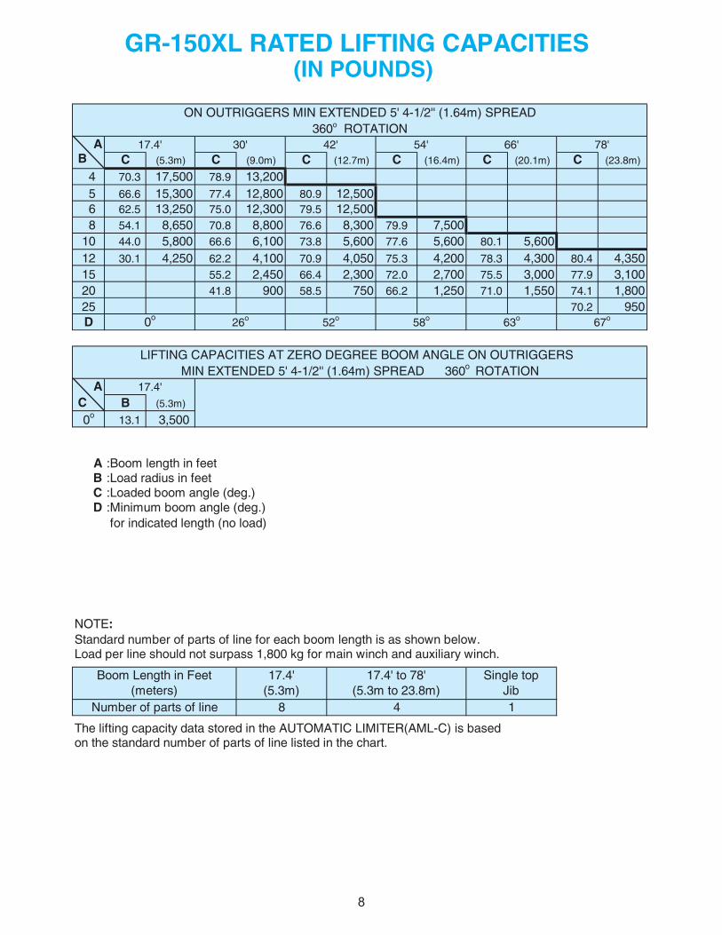
AB C (5.3m) C (9.0m) C (12.7m) C (16.4m) C (20.1m) C (23.8m)
4 70.3 17,500 78.9 13,200 5 66.6 15,300 77.4 12,800 80.9 12,500 6 62.5 13,250 75.0 12,300 79.5 12,500 8 54.1 8,650 70.8 8,800 76.6 8,300 79.9 7,50010 44.0 5,800 66.6 6,100 73.8 5,600 77.6 5,600 80.1 5,60012 30.1 4,250 62.2 4,100 70.9 4,050 75.3 4,200 78.3 4,300 80.4 4,35015 55.2 2,450 66.4 2,300 72.0 2,700 75.5 3,000 77.9 3,10020 41.8 900 58.5 750 66.2 1,250 71.0 1,550 74.1 1,80025 70.2 950D
AC B (5.3m)
0o 13.1 3,500
A :Boom length in feetB :Load radius in feetC :Loaded boom angle (deg.)D :Minimum boom angle (deg.)
for indicated length (no load)
NOTE:Standard number of parts of line for each boom length is as shown below.Load per line should not surpass 1,800 kg for main winch and auxiliary winch.
The lifting capacity data stored in the AUTOMATIC LIMITER(AML-C) is basedon the standard number of parts of line listed in the chart.
GR-150XL RATED LIFTING CAPACITIES (IN POUNDS)
42'
17.4'
17.4' 30'
58o
ON OUTRIGGERS MIN EXTENDED 5' 4-1/2'' (1.64m) SPREAD360o ROTATION
0o 26o 52o 67o
LIFTING CAPACITIES AT ZERO DEGREE BOOM ANGLE ON OUTRIGGERS
54' 66' 78'
63o
Single topJib18
MIN EXTENDED 5' 4-1/2'' (1.64m) SPREAD 360o ROTATION
Boom Length in Feet(meters)
Number of parts of line
17.4' to 78'(5.3m to 23.8m)
4
17.4'(5.3m)
8 8
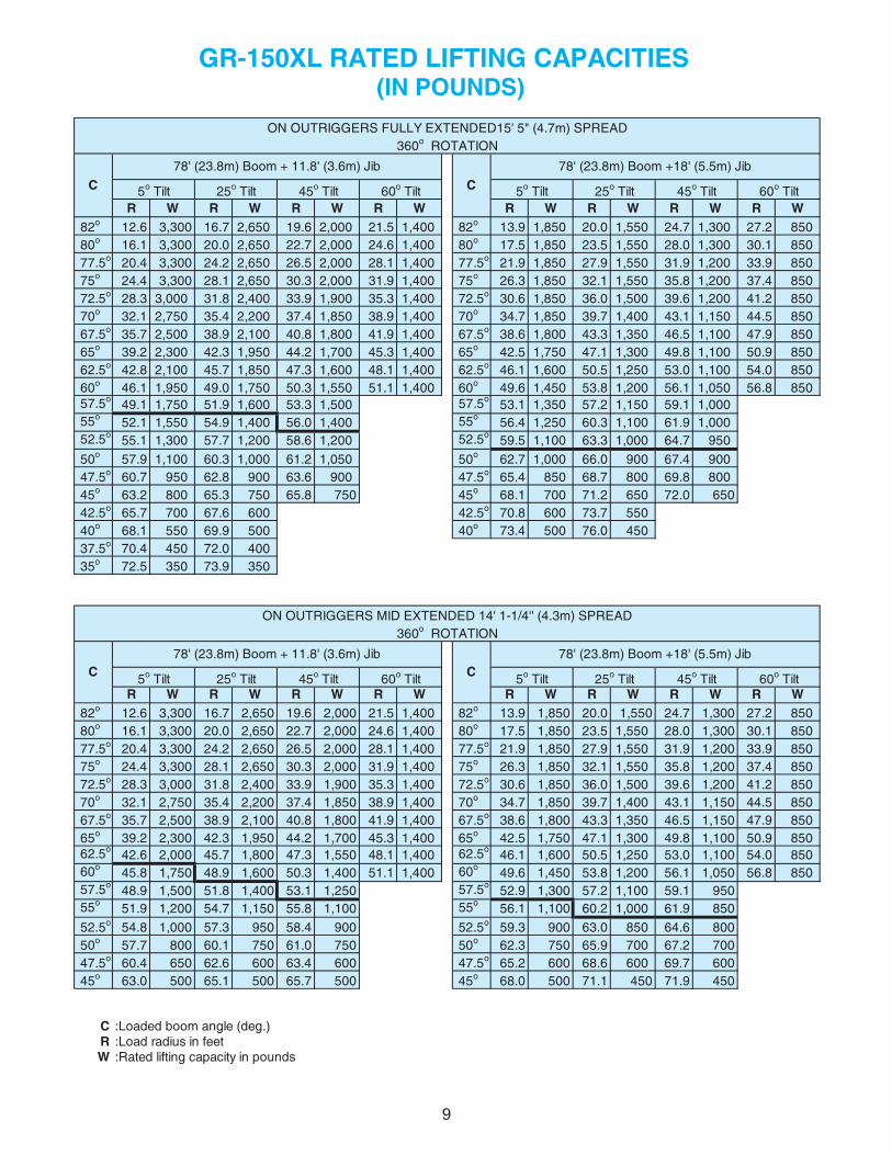
R W R W R W R W R W R W R W R W 82o 12.6 3,300 16.7 2,650 19.6 2,000 21.5 1,400 82o 13.9 1,850 20.0 1,550 24.7 1,300 27.2 850 80o 16.1 3,300 20.0 2,650 22.7 2,000 24.6 1,400 80o 17.5 1,850 23.5 1,550 28.0 1,300 30.1 850 77.5o 20.4 3,300 24.2 2,650 26.5 2,000 28.1 1,400 77.5o 21.9 1,850 27.9 1,550 31.9 1,200 33.9 850 75o 24.4 3,300 28.1 2,650 30.3 2,000 31.9 1,400 75o 26.3 1,850 32.1 1,550 35.8 1,200 37.4 850 72.5o 28.3 3,000 31.8 2,400 33.9 1,900 35.3 1,400 72.5o 30.6 1,850 36.0 1,500 39.6 1,200 41.2 850 70o 32.1 2,750 35.4 2,200 37.4 1,850 38.9 1,400 70o 34.7 1,850 39.7 1,400 43.1 1,150 44.5 850 67.5o 35.7 2,500 38.9 2,100 40.8 1,800 41.9 1,400 67.5o 38.6 1,800 43.3 1,350 46.5 1,100 47.9 850 65o 39.2 2,300 42.3 1,950 44.2 1,700 45.3 1,400 65o 42.5 1,750 47.1 1,300 49.8 1,100 50.9 850 62.5o 42.8 2,100 45.7 1,850 47.3 1,600 48.1 1,400 62.5o 46.1 1,600 50.5 1,250 53.0 1,100 54.0 850 60o 46.1 1,950 49.0 1,750 50.3 1,550 51.1 1,400 60o 49.6 1,450 53.8 1,200 56.1 1,050 56.8 850 57.5o 49.1 1,750 51.9 1,600 53.3 1,500 57.5o 53.1 1,350 57.2 1,150 59.1 1,000 55o 52.1 1,550 54.9 1,400 56.0 1,400 55o 56.4 1,250 60.3 1,100 61.9 1,000 52.5o 55.1 1,300 57.7 1,200 58.6 1,200 52.5o 59.5 1,100 63.3 1,000 64.7 950
50o 57.9 1,100 60.3 1,000 61.2 1,050 50o 62.7 1,000 66.0 900 67.4 900 47.5o 60.7 950 62.8 900 63.6 900 47.5o 65.4 850 68.7 800 69.8 800 45o 63.2 800 65.3 750 65.8 750 45o 68.1 700 71.2 650 72.0 650 42.5o 5.24 0066.760077.56 o 70.8 600 73.7 550 40o 04 0059.960551.86 o 73.4 500 76.0 450 37.5o 70.4 450 72.0 400 35o 72.5 350 73.9 350
R W R W R W R W R W R W R W R W 82o 12.6 3,300 16.7 2,650 19.6 2,000 21.5 1,400 82o 13.9 1,850 20.0 1,550 24.7 1,300 27.2 850 80o 16.1 3,300 20.0 2,650 22.7 2,000 24.6 1,400 80o 17.5 1,850 23.5 1,550 28.0 1,300 30.1 850 77.5o 20.4 3,300 24.2 2,650 26.5 2,000 28.1 1,400 77.5o 21.9 1,850 27.9 1,550 31.9 1,200 33.9 850 75o 24.4 3,300 28.1 2,650 30.3 2,000 31.9 1,400 75o 26.3 1,850 32.1 1,550 35.8 1,200 37.4 850 72.5o 28.3 3,000 31.8 2,400 33.9 1,900 35.3 1,400 72.5o 30.6 1,850 36.0 1,500 39.6 1,200 41.2 850 70o 32.1 2,750 35.4 2,200 37.4 1,850 38.9 1,400 70o 34.7 1,850 39.7 1,400 43.1 1,150 44.5 850 67.5o 35.7 2,500 38.9 2,100 40.8 1,800 41.9 1,400 67.5o 38.6 1,800 43.3 1,350 46.5 1,150 47.9 850 65o 39.2 2,300 42.3 1,950 44.2 1,700 45.3 1,400 65o 42.5 1,750 47.1 1,300 49.8 1,100 50.9 850 62.5o 42.6 2,000 45.7 1,800 47.3 1,550 48.1 1,400 62.5o 46.1 1,600 50.5 1,250 53.0 1,100 54.0 850 60o 45.8 1,750 48.9 1,600 50.3 1,400 51.1 1,400 60o 49.6 1,450 53.8 1,200 56.1 1,050 56.8 850 57.5o 48.9 1,500 51.8 1,400 53.1 1,250 57.5o 52.9 1,300 57.2 1,100 59.1 950 55o 51.9 1,200 54.7 1,150 55.8 1,100 55o 56.1 1,100 60.2 1,000 61.9 850
52.5o 54.8 1,000 57.3 950 58.4 900 52.5o 59.3 900 63.0 850 64.6 800 50o 57.7 800 60.1 750 61.0 750 50o 62.3 750 65.9 700 67.2 700 47.5o 60.4 650 62.6 600 63.4 600 47.5o 65.2 600 68.6 600 69.7 600 45o 63.0 500 65.1 500 65.7 500 45o 68.0 500 71.1 450 71.9 450
C :Loaded boom angle (deg.)R :Load radius in feetW :Rated lifting capacity in pounds
60o Tilt
60o Tilt60o Tilt
ON OUTRIGGERS FULLY EXTENDED15' 5" (4.7m) SPREAD
5o Tilt
5o Tilt 25o Tilt 45o 5tliT o Tilt
25o Tilt
GR-150XL RATED LIFTING CAPACITIES (IN POUNDS)
45o TiltC
360o ROTATION
CbiJ )m5.5( '81+ mooB )m8.32( '87biJ )m6.3( '8.11 + mooB )m8.32( '87
60o 52tliT o Tilt
45o Tilt
ON OUTRIGGERS MID EXTENDED 14' 1-1/4'' (4.3m) SPREAD360o ROTATION
C78' (23.8m) Boom + 11.8' (3.6m) Jib
C78' (23.8m) Boom +18' (5.5m) Jib
5o Tilt 25o Tilt 45o Tilt
9 9
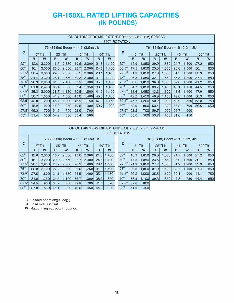
R W R W R W R W R W R W R W R W 82o 12.6 3,300 16.7 2,650 19.6 2,000 21.5 1,400 82o 13.9 1,850 20.0 1,550 24.7 1,300 27.2 850 80o 16.1 3,300 20.0 2,650 22.7 2,000 24.6 1,400 80.5o 17.5 1,850 23.5 1,550 28.0 1,300 30.1 850 77.5o 20.4 3,300 24.2 2,650 26.5 2,000 28.1 1,400 77.5o 21.9 1,850 27.9 1,550 31.9 1,200 33.9 850 75o 24.4 3,300 28.1 2,650 30.3 2,000 31.9 1,400 75o 26.3 1,850 32.1 1,550 35.8 1,200 37.4 850 72.5o 28.3 2,850 31.8 2,400 33.9 1,900 35.3 1,400 72.5o 30.6 1,850 36.0 1,500 39.6 1,200 41.2 850
70o 31.8 2,400 35.4 2,200 37.4 1,850 38.9 1,400 70o 34.7 1,850 39.7 1,400 43.1 1,150 44.5 850 67.5o 35.3 2,000 38.7 1,850 40.8 1,600 41.9 1,400 67.5o 38.6 1,650 43.3 1,300 46.5 1,100 47.9 850 65o 38.7 1,550 41.9 1,500 43.8 1,400 45.3 1,400 65o 42.2 1,450 46.9 1,150 49.8 1,000 50.9 850 62.5o 42.0 1,200 45.7 1,200 46.9 1,150 47.9 1,150 62.5o 45.7 1,200 50.2 1,000 52.9 850 53.8 750
60o 45.2 900 48.9 950 49.8 900 50.7 900 60o 48.9 900 53.4 800 55.8 700 56.6 650 57.5o 48.3 700 51.8 750 52.6 700 57.5o 52.2 700 56.7 600 58.7 600 55o 51.4 550 54.2 550 55.4 500 55o 55.6 500 59.7 450 61.6 450
R W R W R W R W R W R W R W R W 82o 12.6 3,300 16.7 2,650 19.6 2,000 21.5 1,400 82o 13.9 1,850 20.0 1,550 24.7 1,300 27.2 850 80o 16.1 3,200 20.0 2,650 22.7 2,000 24.6 1,400 80o 17.5 1,850 23.5 1,550 28.0 1,300 30.1 850 77.5o 20.1 2,850 23.9 2,300 26.3 1,900 28.1 1,400 77.5o 21.9 1,850 27.7 1,500 31.9 1,200 33.9 850 75o 23.9 2,400 27.7 2,000 30.0 1,750 31.9 1,400 75o 26.3 1,850 31.9 1,400 35.7 1,100 37.4 850 72.5o 27.5 1,800 31.1 1,550 33.5 1,400 35.1 1,150 72.5o 30.2 1,500 35.5 1,100 39.1 900 41.1 750
70o 31.0 1,250 34.5 1,100 36.7 1,000 38.3 850 70o 33.9 1,100 39.3 850 42.8 750 44.4 650 67.5o 34.5 900 37.9 800 39.9 700 41.4 570 67.5o 37.6 800 65o 37.8 550 41.1 500 43.0 450 44.3 300 65o 41.0 450
C :Loaded boom angle (deg.)R :Load radius in feetW :Rated lifting capacity in pounds
60o Tilt
60o Tilt
GR-150XL RATED LIFTING CAPACITIES (IN POUNDS)
ON OUTRIGGERS MID EXTENDED 11' 5-3/4'' (3.5m) SPREAD360o ROTATION
C78' (23.8m) Boom +18' (5.5m) Jib
45o Tilt5o Tilt 25o Tilt 60o Tilt
ON OUTRIGGERS MID EXTENDED 8' 2-3/8'' (2.5m) SPREAD
45o Tilt
C78' (23.8m) Boom + 11.8' (3.6m) Jib
5o Tilt 25o Tilt 45o Tilt
360o ROTATION
C78' (23.8m) Boom + 11.8' (3.6m) Jib
C78' (23.8m) Boom +18' (5.5m) Jib
5o Tilt 25o Tilt 45o 5tliT o Tilt 25o Tilt 60o Tilt
10 10
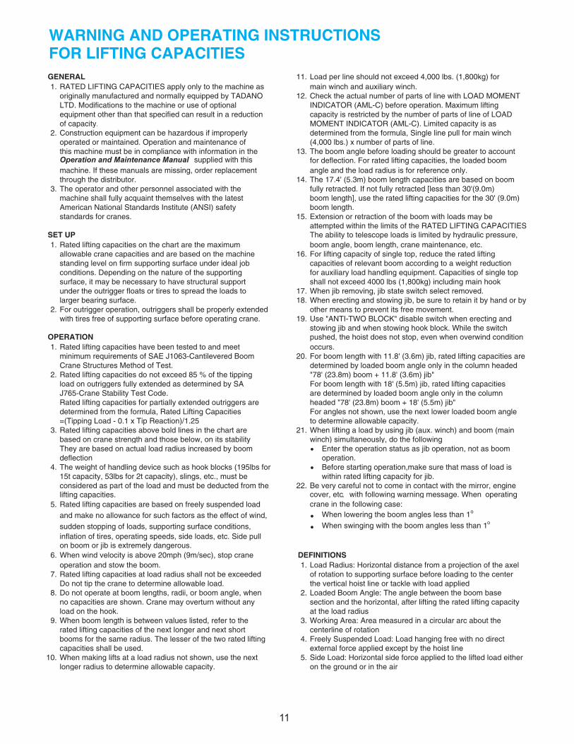
WARNING AND OPERATING INSTRUCTIONSFOR LIFTING CAPACITIESGENERAL 11.1. RATED LIFTING CAPACITIES apply only to the machine as
originally manufactured and normally equipped by TADANO 12.LTD. Modifications to the machine or use of optionalequipment other than that specified can result in a reductionof capacity.
2. Construction equipment can be hazardous if improperlyoperated or maintained. Operation and maintenance of this machine must be in compliance with information in the 13.Operation and Maintenance Manual supplied with thismachine. If these manuals are missing, order replacementthrough the distributor. 14.
3. The operator and other personnel associated with themachine shall fully acquaint themselves with the latestAmerican National Standards Institute (ANSI) safety
.51s.enarc rof sdradnats
SET UP1. Rated lifting capacities on the chart are the maximum
allowable crane capacities and are based on the machine 16.standing level on firm supporting surface under ideal jobconditions. Depending on the nature of the supportingsurface, it may be necessary to have structural supportunder the outrigger floats or tires to spread the loads to 17.larger bearing surface. 18.
2. For outrigger operation, outriggers shall be properly extendedwith tires free of supporting surface before operating crane. 19.
OPERATION1. Rated lifting capacities have been tested to and meet
minimum requirements of SAE J1063-Cantilevered Boom 20.Crane Structures Method of Test.
2. Rated lifting capacities do not exceed 85 % of the tippingload on outriggers fully extended as determined by SAJ765-Crane Stability Test Code.Rated lifting capacities for partially extended outriggers aredetermined from the formula, Rated Lifting Capacities=(Tipping Load - 0.1 x Tip Reaction)/1.25
3. Rated lifting capacities above bold lines in the chart arebased on crane strength and those below, on its stabilityThey are based on actual load radius increased by boom • Enter the operation status as jib operation, not as boomdeflection. operation.
4. The weight of handling device such as hook blocks (195lbs for • Before starting operation,make sure that mass of load is 15t capacity, 53lbs for 2t capacity), slings, etc., must be within rated lifting capacity for jib.considered as part of the load and must be deducted from the 22.lifting capacities.
5. Rated lifting capacities are based on freely suspended loadand make no allowance for such factors as the effect of wind, • When lowering the boom angles less than 1o
sudden stopping of loads, supporting surface conditions, • When swinging with the boom angles less than 1o
inflation of tires, operating speeds, side loads, etc. Side pullon boom or jib is extremely dangerous.
6. When wind velocity is above 20mph (9m/sec), stop crane DEFINITIONSoperation and stow the boom. 1.
7. Rated lifting capacities at load radius shall not be exceededDo not tip the crane to determine allowable load.
8. Do not operate at boom lengths, radii, or boom angle, when 2.no capacities are shown. Crane may overturn without anyload on the hook.
9. When boom length is between values listed, refer to the 3.rated lifting capacities of the next longer and next shortbooms for the same radius. The lesser of the two rated lifting 4.capacities shall be used.
10. When making lifts at a load radius not shown, use the next 5.longer radius to determine allowable capacity.
Side Load: Horizontal side force applied to the lifted load eitheron the ground or in the air
Working Area: Area measured in a circular arc about thecenterline of rotationFreely Suspended Load: Load hanging free with no directexternal force applied except by the hoist line
Load Radius: Horizontal distance from a projection of the axelof rotation to supporting surface before loading to the center the vertical hoist line or tackle with load appliedLoaded Boom Angle: The angle between the boom basesection and the horizontal, after lifting the rated lifting capacityat the load radius
Load per line should not exceed 4,000 lbs. (1,800kg) formain winch and auxiliary winch.Check the actual number of parts of line with LOAD MOMENTINDICATOR (AML-C) before operation. Maximum liftingcapacity is restricted by the number of parts of line of LOADMOMENT INDICATOR (AML-C). Limited capacity is asdetermined from the formula, Single line pull for main winch(4,000 lbs.) x number of parts of line.The boom angle before loading should be greater to accountfor deflection. For rated lifting capacities, the loaded boomangle and the load radius is for reference only.The 17.4' (5.3m) boom length capacities are based on boomfully retracted. If not fully retracted [less than 30'(9.0m)boom length], use the rated lifting capacities for the 30' (9.0m)boom length.Extension or retraction of the boom with loads may beattempted within the limits of the RATED LIFTING CAPACITIESThe ability to telescope loads is limited by hydraulic pressure,boom angle, boom length, crane maintenance, etc.For lifting capacity of single top, reduce the rated liftingcapacities of relevant boom according to a weight reductionfor auxiliary load handling equipment. Capacities of single topshall not exceed 4000 lbs (1,800kg) including main hookWhen jib removing, jib state switch select removed.When erecting and stowing jib, be sure to retain it by hand or byother means to prevent its free movement.Use "ANTI-TWO BLOCK" disable switch when erecting andstowing jib and when stowing hook block. While the switch pushed, the hoist does not stop, even when overwind conditionoccurs.For boom length with 11.8' (3.6m) jib, rated lifting capacities aredetermined by loaded boom angle only in the column headed"78' (23.8m) boom + 11.8' (3.6m) jib"For boom length with 18' (5.5m) jib, rated lifting capacitiesare determined by loaded boom angle only in the columnheaded "78' (23.8m) boom + 18' (5.5m) jib"
crane in the following case:
For angles not shown, use the next lower loaded boom angleto determine allowable capacity.When lifting a load by using jib (aux. winch) and boom (mainwinch) simultaneously, do the following
Be very careful not to come in contact with the mirror, enginecover, etc, with following warning message. When operating
11
21.
11
•
•
••
AB C (5.3m) C (9.0m) C (12.7m) C (5.3m) C (9.0m) C (12.7m)
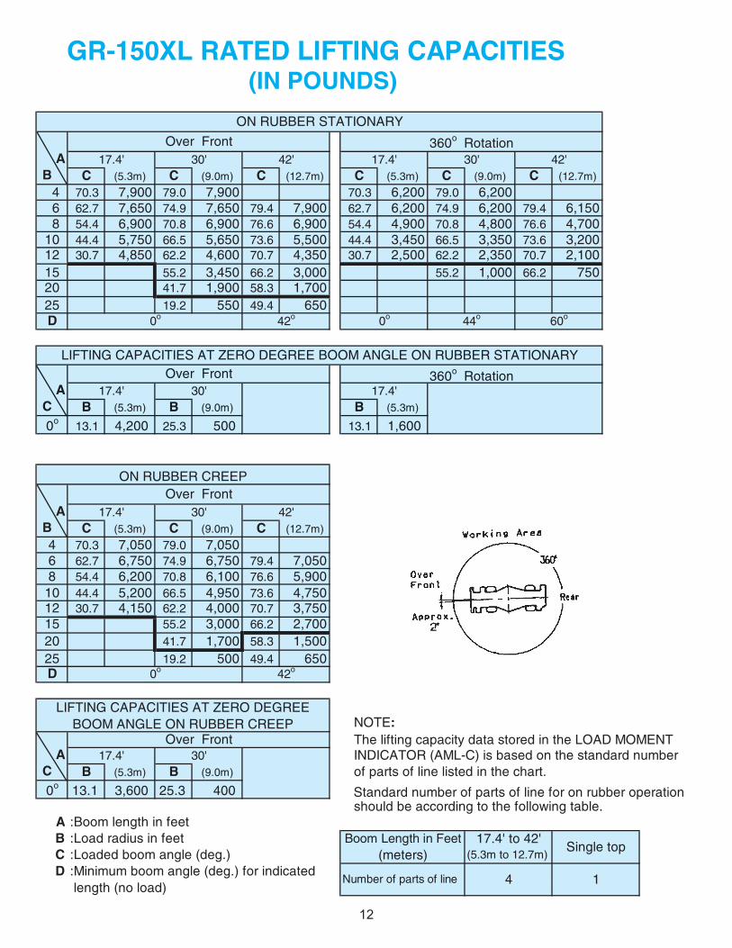
4 70.3 7,900 79.0 7,900 70.3 6,200 79.0 6,200 6 62.7 7,650 74.9 7,650 79.4 7,900 62.7 6,200 74.9 6,200 79.4 6,150 8 54.4 6,900 70.8 6,900 76.6 6,900 54.4 4,900 70.8 4,800 76.6 4,70010 44.4 5,750 66.5 5,650 73.6 5,500 44.4 3,450 66.5 3,350 73.6 3,20012 30.7 4,850 62.2 4,600 70.7 4,350 30.7 2,500 62.2 2,350 70.7 2,10015 55.2 3,450 66.2 3,000 55.2 1,000 66.2 75020 41.7 1,900 58.3 1,70025 19.2 550 49.4 650D
AC B (5.3m) B (9.0m) B (5.3m)
0o 13.1 4,200 25.3 500 13.1 1,600
AB C (5.3m) C (9.0m) C (12.7m)
4 70.3 7,050 79.0 7,0506 62.7 6,750 74.9 6,750 79.4 7,0508 54.4 6,200 70.8 6,100 76.6 5,900
10 44.4 5,200 66.5 4,950 73.6 4,75012 30.7 4,150 62.2 4,000 70.7 3,75015 55.2 3,000 66.2 2,70020 41.7 1,700 58.3 1,50025 19.2 500 49.4 650D
NOTE:
A INDICATOR (AML-C) is based on the standard number C B (5.3m) B (9.0m) of parts of line listed in the chart.0o 13.1 3,600 25.3 400
should be according to the following table.A :Boom length in feetB :Load radius in feetC :Loaded boom angle (deg.)D :Minimum boom angle (deg.) for indicated
length (no load)
60o0o 42o 0o 44o
17.4' 30' 42'17.4' 30' 42'
17.4' 30'
17.4'17.4' 30'
Over Front
LIFTING CAPACITIES AT ZERO DEGREE BOOM ANGLE ON RUBBER CREEP
17.4' 30' 42'
0o 42o
GR-150XL RATED LIFTING CAPACITIES (IN POUNDS)
Over FrontON RUBBER CREEP
ON RUBBER STATIONARY
Over Front 360o Rotation
Over Front 360o Rotation
LIFTING CAPACITIES AT ZERO DEGREE BOOM ANGLE ON RUBBER STATIONARY
The lifting capacity data stored in the LOAD MOMENT
Number of parts of line 4 1
Boom Length in Feet 17.4' to 42'Single top
(meters) (5.3m to 12.7m)
12
Standard number of parts of line for on rubber operation
12
WARNING AND OPERATING INSTRUCTIONSFOR ON RUBBER LIFTING CAPACITIES
5.
6.
7.8.
9.10.
11.
WARNING AND OPERATING INSTRUCTIONSFOR USING THE LOAD MOMENT INDICATOR (AML-C)
.noitarepo peerc roF )2(:sreggirtuo no enarc gnitarepo nehW.1h h
h3.
h Set "P.T.O." switch to "ON".h
4.
h5.
2.h
h6.
hh
7.h
(1)h
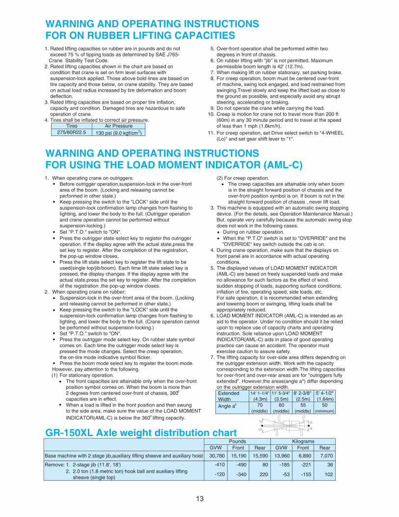
14' 1-1/4" 11' 5-3/4" 8' 2-3/8" 5' 4-1/2" (4.3m) (3.5m) (2.5m) (1.64m)
h Angle ao 70 60 55 50(middle) (middle) (middle) (minimum)
GR-150XL Axle weight distribution chartFront Rear GVW Front Rear
63 122- 581- 08 094-)'81 ,'8.11( bij egats-2 .1:evomeR
-340 220 -53 -155 102
on the outrigger extension width.
exercise caution to assure safety.The lifting capacity for over-side area differs depending onthe outrigger extension width. Work with the capacity corresponding to the extension width.The lifting capacitiesfor over-front and over-rear areas are for "outriggers fullyextended". However,the areas(angle aº) differ depending
LOAD MOMENT INDICATOR (AML-C) is intended as anaid to the operator. Under no condition should it be relied upon to replace use of capacity charts and operating instruction. Sole reliance upon LOAD MOMENT INDICATOR(AML-C) aids in place of good operating practice can cause an accident. The operator must
no allowance for such factors as the effect of wind, sudden stopping of loads, supporting surface conditions,inflation of tire, operating speed, side loads, etc. For safe operation, it is recommended when extending and lowering boom or swinging, lifting loads shall be appropriately reduced.
When a load is lifted in the front position and then swung
does not work in the following cases.h During on rubber operation.h When the "P.T.O" switch is set to "OVERRIDE" and the "OVERRIDE" key switch outside the cab is on.During crane operation, make sure that the displays onfront panel are in accordance with actual operating conditions.The displayed values of LOAD MOMENT INDICATOR(AML-C) are based on freely suspended loads and make
However, pay attention to the following.For stationary operation.
The front capacities are attainable only when the over-frontposition symbol comes on. When the boom is more than 2 degrees from centered over-front of chassis, 360o
capacities are in effect.
Set "P.T.O." switch to "ON".Press the outrigger mode select key. On rubber state symbolcomes on. Each time the outrigger mode select key ispressed the mode changes. Select the creep operation, the on-tire mode indicative symbol flicker.Press the boom mode select key to register the boom mode.
Suspension-lock in the over-front area of the boom. (Lockingand releasing cannot be performed in other state.)Keep pressing the switch to the "LOCK" side until thesuspension-lock confirmation lamp changes from flashing tolighting, and lower the body to the full. (Crane operation cannotbe performed without suspension-locking.)
and crane operation cannot be performed without suspension-locking.)
the pop-up window closes.
of the registration ,the pop-up window closes.When operating crane on rubber:
straight forward position of chassis , never lift load.This machine is equipped with an automatic swing stoppingdevice. (For the details, see Operation Maintenance Manual.)But, operate very carefully because the automatic swing stop
Press the lift state select key to register the lift state to be
area of the boom. (Locking and releasing cannot beperformed in other state.)Keep pressing the switch to the "LOCK" side until thesuspension-lock confirmation lamp changes from flashing tolighting, and lower the body to the full. (Outrigger operation
Before outrigger operation,suspension-lock in the over-front The creep capacities are attainable only when boom is in the straight forward position of chassis and the over-front position symbol is on. If boom is not in the
ExtendedWidth
capacity and condition. Damaged tires are hazardous to safe
operation. If the display agree with the actual state,press the
(Lo)" and set gear shift lever to "1".
set key to register. After the completion of the registration,
Over-front operation shall be performed within two degrees in front of chassis.On rubber lifting with "jib" is not permitted. Maximum permissible boom length is 42' (12.7m).
INDICATOR(AML-C) is below the 360o lifting capacity.
suspension-lock applied. Those above bold lines are based on
Press the outrigger state select key to register the outrigger
3. Rated lifting capacities are based on proper tire inflation,
pressed, the display changes. If the display agree with the actual state,press the set key to register. After the completion
1. Rated lifting capacities on rubber are in pounds and do not exceed 75 % of tipping loads as determined by SAE J765- Crane Stability Test Code.2. Rated lifting capacities shown in the chart are based on
the ground as possible, and especially avoid any abrupt
4. Tires shall be inflated to correct air pressure.
deflection.
When making lift on rubber stationary, set parking brake.For creep operation, boom must be centered over-front
swinging.Travel slowly and keep the lifted load as close to
condition that crane is set on firm level surfaces with
-410
GVW
Do not operate the crane while carrying the load.Creep is motion for crane not to travel more than 200 ft(60m) in any 30 minute period and to travel at the speed of less than 1 mph (1.6km/h).
steering, accelerating or braking.
Tires Air Pressure
15,590 13,960 6,890
of machine, swing lock engaged, and load restrained from tire capacity and those below, on crane stability. They are based on actual load radius increased by tire deformation and boom
operation of crane.
130 psi (9.0 kgf/cm2) For creep operation, set Drive select switch to "4-WHEEL 275/80R22.5
used(single top/jib/boom). Each time lift state select key is
15,190Base machine with 2 stage jib,auxiliary lifting sheeve and auxiliary hoist
Kilograms
to the side area, make sure the value of the LOAD MOMENT
2. 2.0 ton (1.8 metric ton) hook ball and auxiliary lifting sheave (single top)
-120
Pounds
070,7087,03
1313
•
•
••
•
•
•
••
•
•
•
••
•

MEMO
4314

MEMO
4315
MEMO
TADANO AMERICA CORPORATION
4242 WEST GREENS ROADHOUSTON, TEXAS, 77066 U.S.A.PHONE: (281) 869-0030FAX: (281) 869-0040Parts Hotline: (281) 869-0033Service Hotline: (281) 869-5925Web site: www.tadanoamerica.comE-mail: [email protected] No. TAC GR-150XL-1-090604
1416