GPU Accelerated Path-planning for Multi-agents in Virtual ... · GPU Accelerated Path-planning for...
7
GPU Accelerated Path-planning for Multi-agents in Virtual Environments Leonardo G. Fischer, Renato Silveira, Luciana Nedel Institute of Informatics Federal University of Rio Grande do Sul Figure 1: Virtual characters controlled by the BVP Planner in a virtual environment. Abstract Many games are populated by synthetic humanoid actors that act as autonomous agents. The animation of humanoids in real-time applications is yet a challenge if the problem involves attaining a precise location in a virtual world (path-planning), and moving re- alistically according to its own personality, intentions and mood (motion planning). In this paper we present a strategy to imple- ment – using CUDA on GPU – a path planner that produces natural steering behaviors for virtual humans using a numerical solution for boundary value problems. The planner is based on the poten- tial field formalism that allows synthetic actors to move negotiat- ing space, avoiding collisions, and attaining goals, while producing very individual paths. The individuality of each character can be set by changing its inner field parameters leading to a broad range of possible behaviors without jeopardizing its performance. With our GPU-based strategy we achieve a speed up to 56 times the previous implementation, allowing its use in situations with a large number of autonomous characters, which is commonly found in games. Keywords:: Path-planning, GPGPU, NVIDIA CUDA, Agent Simulation Author’s Contact: {lgfischer,rsilveira,nedel}@inf.ufrgs.br 1 Introduction Many types of games, specifically First Person Shooters (FPS) and Real Time Strategy (RTS) are populated by synthetic actors that should act as autonomous agents. Autonomous agents, also called non-player characters, are characters with the ability of playing a role into the environment with life-like and improvisational be- havior. To behave in such way, the agents must act in the virtual world, perceive, react and remember their perceptions about this world, think about the effects of possible actions and finally, learn from their experience [Funge 2004]. In this complex and suitable context, navigation plays an important role [Nieuwenhuisen et al. 2007]. To move agents in a synthetic world, a semantic represen- tation of the environment is needed, as well as the definition of the agent initial and target position (goal). Once these parameters were set, any path-planning algorithm can be used to find a trajectory to be followed. However, in the real world, if we consider different persons (all in the same initial position) looking for achieving the same target position, each path followed will be unique. Even for the same task, the strategy used for each person to reach his/her goal depends on his/her physical constitution, personality, mood, reasoning, ur- gency, and so on. From this point of view, a high quality algorithm to move characters across virtual environments should generate ex- pressive, natural and unexpected steering behaviors. In contrast, the high performance required for real-time graphics applications compels developers to look for most efficient and less expensive methods that produce yet good and almost natural move- ments. To illustrate how performance is a crucial problem, it is known that to be playable, a game must run at least at a rate of 30-100 frames per second. This implies in 0.02 seconds per frame. Each frame (or step of an animation) includes the updating of the game status, handling user inputs, graphics processing, physics computations, strategic AI, path-planning, among others. Then, we can easily consider something as one millisecond per step for path- planning (with multi-core architectures, this restriction is relaxed). Many researchers are working on methods to improve the quality of the steering behavior of synthetic agents with a minimal cost. One way to improve the performance is taking advantage of mas- sively parallel architectures, as multi-core CPUs and GPUs (Graph- ics Processing Unit). In this work we propose a GPU implemen- tation of the BVP Planner recently proposed by us [Dapper et al. 2007]. The BVP Planner is a method based on the numeric solution of the boundary value problem (BVP) to control the movement of pedestrians allowing the individuality of each agent. Our main contributions in this paper are: • A parallel version of our previously technique [Dapper et al. 2007], implemented on the GPU using nVIDIA CUDA (Com- pute Unified Device Architecture) [NVIDIA. 2009] • A strategy to reduce the number of memory transactions be- tween CPU and GPU • Several tests showing that the GPU implementation improves up to 56 times the CPU sequential version, allowing the real- time use of this technique even in scenarios with a large num- ber of autonomous characters Despite humanoid, autonomous agent, and behavior are terms used in many different contexts, in this paper we limit its use in order to match our goals. For the sake of simplicity, we consider humanoids as a kind of embodied autonomous agent with reactive behaviors (driven by stimulus), represented by a computational model, and capable of producing physical manifestations in a virtual world. The term behavior will be used mainly as a synonymous of ani- mation or steering behavior and intend to refer the improvisational and personalized action of a humanoid. The remaining of this paper is structured as follows. Section 2 re- views some related works on path-planning techniques applied to virtual agents simulation. Section 3 describes the fundamentals of the path-planning method proposed by us. In Section 4 we detail the strategy used to handle the information about the environment and other agents. In Section 5 we present our strategy to implement
Transcript of GPU Accelerated Path-planning for Multi-agents in Virtual ... · GPU Accelerated Path-planning for...

GPU Accelerated Path-planning for Multi-agents in Virtual EnvironmentsLeonardo G. Fischer, Renato Silveira, Luciana Nedel
Institute of InformaticsFederal University of Rio Grande do Sul
Figure 1: Virtual characters controlled by the BVP Planner in a virtual environment.
Abstract
Many games are populated by synthetic humanoid actors that actas autonomous agents. The animation of humanoids in real-timeapplications is yet a challenge if the problem involves attaining aprecise location in a virtual world (path-planning), and moving re-alistically according to its own personality, intentions and mood(motion planning). In this paper we present a strategy to imple-ment – using CUDA on GPU – a path planner that produces naturalsteering behaviors for virtual humans using a numerical solutionfor boundary value problems. The planner is based on the poten-tial field formalism that allows synthetic actors to move negotiat-ing space, avoiding collisions, and attaining goals, while producingvery individual paths. The individuality of each character can be setby changing its inner field parameters leading to a broad range ofpossible behaviors without jeopardizing its performance. With ourGPU-based strategy we achieve a speed up to 56 times the previousimplementation, allowing its use in situations with a large numberof autonomous characters, which is commonly found in games.
Keywords:: Path-planning, GPGPU, NVIDIA CUDA, AgentSimulation
Author’s Contact:
{lgfischer,rsilveira,nedel}@inf.ufrgs.br
1 Introduction
Many types of games, specifically First Person Shooters (FPS) andReal Time Strategy (RTS) are populated by synthetic actors thatshould act as autonomous agents. Autonomous agents, also callednon-player characters, are characters with the ability of playinga role into the environment with life-like and improvisational be-havior. To behave in such way, the agents must act in the virtualworld, perceive, react and remember their perceptions about thisworld, think about the effects of possible actions and finally, learnfrom their experience [Funge 2004]. In this complex and suitablecontext, navigation plays an important role [Nieuwenhuisen et al.2007]. To move agents in a synthetic world, a semantic represen-tation of the environment is needed, as well as the definition of theagent initial and target position (goal). Once these parameters wereset, any path-planning algorithm can be used to find a trajectory tobe followed.
However, in the real world, if we consider different persons (allin the same initial position) looking for achieving the same targetposition, each path followed will be unique. Even for the sametask, the strategy used for each person to reach his/her goal dependson his/her physical constitution, personality, mood, reasoning, ur-gency, and so on. From this point of view, a high quality algorithm
to move characters across virtual environments should generate ex-pressive, natural and unexpected steering behaviors.
In contrast, the high performance required for real-time graphicsapplications compels developers to look for most efficient and lessexpensive methods that produce yet good and almost natural move-ments. To illustrate how performance is a crucial problem, it isknown that to be playable, a game must run at least at a rate of30-100 frames per second. This implies in 0.02 seconds per frame.Each frame (or step of an animation) includes the updating of thegame status, handling user inputs, graphics processing, physicscomputations, strategic AI, path-planning, among others. Then, wecan easily consider something as one millisecond per step for path-planning (with multi-core architectures, this restriction is relaxed).
Many researchers are working on methods to improve the qualityof the steering behavior of synthetic agents with a minimal cost.One way to improve the performance is taking advantage of mas-sively parallel architectures, as multi-core CPUs and GPUs (Graph-ics Processing Unit). In this work we propose a GPU implemen-tation of the BVP Planner recently proposed by us [Dapper et al.2007]. The BVP Planner is a method based on the numeric solutionof the boundary value problem (BVP) to control the movement ofpedestrians allowing the individuality of each agent.
Our main contributions in this paper are:
• A parallel version of our previously technique [Dapper et al.2007], implemented on the GPU using nVIDIA CUDA (Com-pute Unified Device Architecture) [NVIDIA. 2009]
• A strategy to reduce the number of memory transactions be-tween CPU and GPU
• Several tests showing that the GPU implementation improvesup to 56 times the CPU sequential version, allowing the real-time use of this technique even in scenarios with a large num-ber of autonomous characters
Despite humanoid, autonomous agent, and behavior are terms usedin many different contexts, in this paper we limit its use in order tomatch our goals. For the sake of simplicity, we consider humanoidsas a kind of embodied autonomous agent with reactive behaviors(driven by stimulus), represented by a computational model, andcapable of producing physical manifestations in a virtual world.The term behavior will be used mainly as a synonymous of ani-mation or steering behavior and intend to refer the improvisationaland personalized action of a humanoid.
The remaining of this paper is structured as follows. Section 2 re-views some related works on path-planning techniques applied tovirtual agents simulation. Section 3 describes the fundamentals ofthe path-planning method proposed by us. In Section 4 we detailthe strategy used to handle the information about the environmentand other agents. In Section 5 we present our strategy to implement

this technique on GPU. Section 6 shows our results, including sev-eral comparisons between the CPU and GPU version, and exposesconsiderations about performance. Finally, Section 7 presents ourconclusions and some ideas for future works.
2 Related Work
The path-planning problem has been deeply explored in game de-velopment. The generation of a path between two known con-figurations in a bi-dimensional world is a well-known problem inrobotics, artificial intelligence, and computer graphics field. How-ever, to find the path is not enough when we want to endow artificialcharacters with natural and realistic movement similar to the onesfound and followed by real human beings. When it comes to agame with many autonomous characters, for instance, these char-acters must also present convincing behavior. It is very difficult toproduce natural behavior by using a strategy focusing on the globalcontrol of characters. On the other hand, taking into account the in-dividuality of each character can be a costly task. As a consequence,most of the approaches proposed in computer graphics literature donot take into account the individual behavior of each agent.
An example is the technique proposed by Kuffner [James J. Kuffner1998]. Kuffner proposed a technique where the scenario is mappedonto a 2D mesh and the path is computed using a dynamic pro-gramming technique like Dijkstra. Then, the motion controller isused to animate the agent along the path planned. Kuffner arguethat his technique is fast enough to be used in dynamic environ-ments. Another example is the work developed by Metoyer andHodgings [Metoyer and Hodgins 2004]. They proposed a tech-nique where the user defines the path that should be followed byeach agent. During the motion along this path, it is smoothed andslightly changed to avoid collisions using force fields that act on theagent.
The development of randomized path-finding algorithms – spe-cially the PRM (Probabilistic Roadmaps) [Kavraki et al. 1996] andRTT (Rapidly-exploring Random Tree) [LaValle 1998] – allowedthe use of large and more complex configuration spaces to generatepaths efficiently. Thus, the challenge becomes more the generationof realistic movements than finding a valid path. For instance, Choiet al. [Choi et al. 2003] use a library of captured movements asso-ciated to the PRM to generate realistic movements in a static envi-ronment, that is, live-captured motions are used insofar the agenttracks the path computed from a roadmap. Despite the fact the pathis computed in a pre-processing phase, results are very realistic.Pettre et al. [Pettre et al. 2002] improved this idea adding one morestep in this process. This step consists of smoothing the path com-puted by the PRM using Bezier curves. Hereinafter, the alreadycaptured motions are associated to the agent position during thepath execution. As in previous works, the motion is also performedon a 2D environment.
Differently, Burgess and Darken [Burgess and Darken 2004] pro-posed a method based on the principle of least action which de-scribes the tendency of elements in nature to seek the minimal ef-fort solution. Authors claim that a realistic path for a human is theone that requires the smallest amount of effort. The method pro-duces human-like movements, through very realistic paths, usingproperties of fluid simulation.
Tecchia et al. [Tecchia et al. 2001] proposed a platform that aimsto accelerate the development of behaviors for agents through localrules that control these behaviors. These rules are governed by fourdifferent control levels, where each one reflects a different aspectof the behavior of the agent. Results show that, for a fairly simplebehavioral model, the system performance can achieve interactivetime.
Pelechano et al. [Pelechano et al. 2005] described a new architec-ture to integrate a psychological model into a crowd simulation sys-tem in order to obtain believable emergent behaviors. The architec-ture achieves individualistic behaviors through the modeling of theagent knowledge, as well as the basic principles of communicationbetween agents.
Treuille et al. [Treuille et al. 2006] proposed a crowd simulator
driven by dynamic potential fields which integrates both global nav-igation and local collision avoidance. Basically, this technique usesthe crowd as a density field, and, for each group, constructs a unitcost field which is used to control people displacement. The methodproduces smooth behavior for a large amount of agents at interac-tive rates.
Recently, Reynolds [Reynolds 2006] implemented a high perfor-mance multi-agent simulation and animation for the Playstation R©
3. Basically, his technique uses a spatial partitioning that dividesthe simulation into disjoint jobs which are evaluated in an arbitraryorder on any number of Playstation R© 3 Synergistic Processor Units(SPUs). A fine-grain partitioning suits SPU memory size and pro-vides automatic load balancing. This approach allows a scalablemulti-processor implementation of a large and fast crowd simula-tion, achieving good frame rates with thousand of agents.
In 2008, Bleiweiss [Bleiweiss 2008] implemented the Dijkstra andthe A* algorithms using CUDA. Differently from our work, thesealgorithms are used in the path finding problem with pre-computedgraphs. After several benchmarks, he observed that the Dijkstraimplementation reached a speed up of 27 times compared to a C++implementation without SSE instructions. The A* implementationreached a speed up of 24 times compared to the C++ implementa-tion with SSE instructions.
Based on local control, van den Berg [van den Berg et al. 2008]proposed a technique that handles the navigation of multiple agentsin the presence of dynamic obstacles. He uses an extended velocityobstacles concept to locally control the agents with few oscillation.Kapadia [Kapadia et al. 2009] presented a framework that enablesagents to navigate in unknown environments based on affordancefields that compute all the possible ways an agent can interact withits environment.
As mentioned above, most of the approaches do not take into ac-count the individual behavior of each agent, his internal state ormood. Our assumption is that realistic paths derive from humanpersonal characteristics and internal state, thus varying from oneperson to another. As a consequence, we [Dapper et al. 2006; Dap-per et al. 2007] recently proposed a technique that generate individ-ual paths. Our path is smooth and is dynamically generated whilethe agent walks. In the following sections, we will explain the con-cepts of our technique and our strategy to implement it on the GPU.
3 Path Planner based on Boundary ValueProblems
Recently, we [Dapper et al. 2006; Dapper et al. 2007] developeda technique that produces natural and individual behaviors for vir-tual humanoids. This technique is based on an extension of theLaplace’s Equation that produces a family of potential field func-tions that do not have local minima. This family is generatedthrough the numeric solution of a convenient partial differentialequation with Dirichlet boundary conditions, i.e., a boundary valueproblem (BVP). Boundary conditions are central to the method in-dicating which regions in the environment are obstacles and whichones are targets. Our method uses the following equation
∇2 p(r) + εv.∇p(r) = 0 (1)
where v is a bias unity vector and ε is a scalar value.
The use of terms ε and v distort the potential field providing a pre-ferred direction to be followed. This distortion allows the produc-tion of individual behaviors for humanoids illustrated through thepath followed by each one during navigation tasks.
To generate realistic steering behaviors, we need to convenientlyadjust both parameters ε and v. The vector v, called behavior vec-tor, can be thought as an external force that pulls the agent to itsdirection always as possible whereas the parameter ε can be under-stood as the strength or influence of this vector in the agent behav-ior. The allowed values of parameters ε and v permit to generate anexpressive amount of action sequences – displacement sequences –that virtual humanoids can use to reach a specific target position.
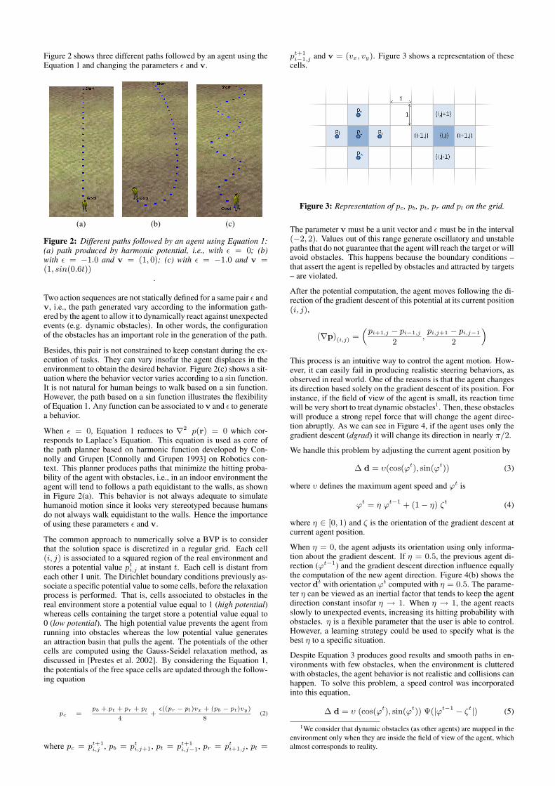
Figure 2 shows three different paths followed by an agent using theEquation 1 and changing the parameters ε and v.
(a) (b) (c)
Figure 2: Different paths followed by an agent using Equation 1:(a) path produced by harmonic potential, i.e., with ε = 0; (b)with ε = −1.0 and v = (1, 0); (c) with ε = −1.0 and v =(1, sin(0.6t))
.
Two action sequences are not statically defined for a same pair ε andv, i.e., the path generated vary according to the information gath-ered by the agent to allow it to dynamically react against unexpectedevents (e.g. dynamic obstacles). In other words, the configurationof the obstacles has an important role in the generation of the path.
Besides, this pair is not constrained to keep constant during the ex-ecution of tasks. They can vary insofar the agent displaces in theenvironment to obtain the desired behavior. Figure 2(c) shows a sit-uation where the behavior vector varies according to a sin function.It is not natural for human beings to walk based on a sin function.However, the path based on a sin function illustrates the flexibilityof Equation 1. Any function can be associated to v and ε to generatea behavior.
When ε = 0, Equation 1 reduces to ∇2 p(r) = 0 which cor-responds to Laplace’s Equation. This equation is used as core ofthe path planner based on harmonic function developed by Con-nolly and Grupen [Connolly and Grupen 1993] on Robotics con-text. This planner produces paths that minimize the hitting proba-bility of the agent with obstacles, i.e., in an indoor environment theagent will tend to follows a path equidistant to the walls, as shownin Figure 2(a). This behavior is not always adequate to simulatehumanoid motion since it looks very stereotyped because humansdo not always walk equidistant to the walls. Hence the importanceof using these parameters ε and v.
The common approach to numerically solve a BVP is to considerthat the solution space is discretized in a regular grid. Each cell(i, j) is associated to a squared region of the real environment andstores a potential value pt
i,j at instant t. Each cell is distant fromeach other 1 unit. The Dirichlet boundary conditions previously as-sociate a specific potential value to some cells, before the relaxationprocess is performed. That is, cells associated to obstacles in thereal environment store a potential value equal to 1 (high potential)whereas cells containing the target store a potential value equal to0 (low potential). The high potential value prevents the agent fromrunning into obstacles whereas the low potential value generatesan attraction basin that pulls the agent. The potentials of the othercells are computed using the Gauss-Seidel relaxation method, asdiscussed in [Prestes et al. 2002]. By considering the Equation 1,the potentials of the free space cells are updated through the follow-ing equation
pc =pb + pt + pr + pl
4+ε((pr − pl)vx + (pb − pt)vy)
8(2)
where pc = pt+1i,j , pb = pt
i,j+1, pt = pt+1i,j−1, pr = pt
i+1,j , pl =
pt+1i−1,j and v = (vx, vy). Figure 3 shows a representation of these
cells.
Figure 3: Representation of pc, pb, pt, pr and pl on the grid.
The parameter v must be a unit vector and ε must be in the interval(−2, 2). Values out of this range generate oscillatory and unstablepaths that do not guarantee that the agent will reach the target or willavoid obstacles. This happens because the boundary conditions –that assert the agent is repelled by obstacles and attracted by targets– are violated.
After the potential computation, the agent moves following the di-rection of the gradient descent of this potential at its current position(i, j),
(∇p)(i,j) =(pi+1,j − pi−1,j
2,pi,j+1 − pi,j−1
2
)This process is an intuitive way to control the agent motion. How-ever, it can easily fail in producing realistic steering behaviors, asobserved in real world. One of the reasons is that the agent changesits direction based solely on the gradient descent of its position. Forinstance, if the field of view of the agent is small, its reaction timewill be very short to treat dynamic obstacles1. Then, these obstacleswill produce a strong repel force that will change the agent direc-tion abruptly. As we can see in Figure 4, if the agent uses only thegradient descent (dgrad) it will change its direction in nearly π/2.
We handle this problem by adjusting the current agent position by
∆ d = υ(cos(ϕt), sin(ϕt)) (3)
where υ defines the maximum agent speed and ϕt is
ϕt = η ϕt−1 + (1− η) ζt (4)
where η ∈ [0, 1) and ζ is the orientation of the gradient descent atcurrent agent position.
When η = 0, the agent adjusts its orientation using only informa-tion about the gradient descent. If η = 0.5, the previous agent di-rection (ϕt−1) and the gradient descent direction influence equallythe computation of the new agent direction. Figure 4(b) shows thevector dt with orientation ϕt computed with η = 0.5. The parame-ter η can be viewed as an inertial factor that tends to keep the agentdirection constant insofar η → 1. When η → 1, the agent reactsslowly to unexpected events, increasing its hitting probability withobstacles. η is a flexible parameter that the user is able to control.However, a learning strategy could be used to specify what is thebest η to a specific situation.
Despite Equation 3 produces good results and smooth paths in en-vironments with few obstacles, when the environment is clutteredwith obstacles, the agent behavior is not realistic and collisions canhappen. To solve this problem, a speed control was incorporatedinto this equation,
∆ d = υ (cos(ϕt), sin(ϕt)) Ψ(|ϕt−1 − ζt|) (5)
1We consider that dynamic obstacles (as other agents) are mapped in theenvironment only when they are inside the field of view of the agent, whichalmost corresponds to reality.

(a)
(b)
Figure 4: Defining agent motion. (a) Situation before the agent A2
enters in the field of view of A1. (b) If the agent A1 follows thedirection defined by the gradient descent (dgrad), it will changesits direction in nearly π/2, what is undesirable. However, if theagent uses the vector d, it will achieve a smooth curve, what ismore natural and realistic.
where function Ψ : R→ R is
Ψ(x) =
{0 if x > π/2cos(x) , otherwise .
If |ϕt−1− ζt| is higher than π/2, then there is a high hitting proba-bility and this function returns the value 0, making the agent stops.Otherwise, the agent speed will change proportionally to the col-lision risk. In regions cluttered with obstacles, agents will tend tomove slowly. If a given agent is about to cross the path of another,one of them will stop and wait until the other get through. Further-more, speed control allows the simulation of agents’ mood throughthe variation of the speed magnitude, that is, it is possible to simu-late a tired agent making it move slower and an agent that is anxiousabout its work making it move faster.
4 Implementation Strategy
As previously explained, our motion planning method requires thediscretization of the environment into a regular grid. In this sectionwe present the strategy that was used in our previous work [Dapperet al. 2006; Dapper et al. 2007] to implement it by using globalenvironment maps (one for each target) and local maps (one foreach agent), as well as the mechanisms used to control each agentsteering behavior.
4.1 Environment Global Map
The entire environment is represented by a set of homogeneousmeshes, {Mk}, in which each meshMk has Lx × Ly cells, de-noted by {Ck
i,j}. Each cell Cki,j corresponds to a squared region
centered in environment coordinates r = (ri, rj) and stores a par-ticular potential value Pk
i,j . The potential associated to the meshMk is computed by the harmonic path planner, through the Equa-tion 2, and then used by agents to reach the target Ok.
In order to delimit the navigation space, we consider that the en-vironment is surrounded by static obstacles. Global maps are builtbefore simulation starts, in a pre-processing phase.
4.2 Agent Local Map
Each agent ak has one map mk that stores the current local infor-mation about the environment obtained by its own sensors. Thismap is centered in the current agent position and represents a smallfraction of the global map, usually about 10% of the total area cov-ered by the global map.
The map mk has lkx × lky cells, denoted by {cki,j} and divided inthree regions: the update zone (u-zone); the free zone (f-zone) andthe border zone (b-zone), as shown in Figure 5. Each cell corre-sponds to a squared region centered in environment coordinatesr = (ri, rj) and stores a particular potential value pk
i,j .
Figure 5: Agent Local Map. The update (u-zone), free (f-zone) andborder zones (b-zone) are shown. Blue and red cells correspond tothe intermediate goal and obstacles, respectively.
The area associated to each agent map cell is smaller than the areaassociated to the global map cell. The main reason is that the agentmap is used to produce refined motion, while the global map is usedonly to assist the long-term agent navigation. Hence, the smaller thesize of the cell on the local map, the better the quality of motion.
4.3 Updating Local Maps from Global Maps
For each agent ak, a goal Ogoal(k)2, a particular vector vk that
controls its behavior, and a εk should be stated. The same goal, v,and ε can be designated to several agents. If vk or εk is dynamic,then the function that controls it must also be specified.
To navigate into the environment, an agent ak uses its sensors toperceive the world and to update its local map with informationabout obstacles and other agents. The agent sensor sets a view conewith aperture α.
Figure 6 exemplifies a particular instance of the agent local mapwhere we can see the obstacles mapped from the global map. Theu-zone cells cki,j which are inside the view cone and correspondto obstacles or other agents have their potential value set to 1. InFigure 7, as there is an agent in the u-zone of the agent local map,inside of his view cone, it is mapped as an obstacle into his localmap. This procedure assures that dynamic or static obstacles behindthe agent (out of his view cone) do not interfere in his future motion.
For each agent ak, the global descent gradient on the cell in theglobal map Mgoal(k) that contains his current position is calcu-lated. The gradient direction is used to generate an intermediategoal in the border of the local map, setting the potential values of acouple of b-zone cells to 0, while the other b-zone cells are consid-ered as obstacles, with their potential values set to 1. In Figure 7,the agent calculates his global gradient in order to project an in-termediate goal in its own local map. As the agent local map isdelimited by obstacles, the agent is pulled towards the intermediategoal using the direction of his local gradient. The intermediate goalhelps the agent ak to reach its target Ogoal(k) while allowing it toproduce a particular motion.
2Function goal() maps the agent number k into its current target number

Figure 6: Global map mapped onto the agent local map.
Figure 7: The cells which are inside the agent’s view cone andcorrespond to obstacles or other agents have their potential valueset to 1.
In some cases, the target Ogoal(k) is inside both view cone and u-zone, and consequently local map cells associated are set to 0. Theintermediate goal is always projected, even if the target is mappedonto the u-zone. Otherwise the agent can easily get trapped be-cause it would be taking into consideration only the local informa-tion about the environment, in a same way as traditional potentialfields [Khatib 1980].
F-zone cells are always considered free of obstacles, even whenthere are obstacles inside. The absence of this zone may close theconnection between the current agent cell and the intermediate goaldue to the mapping of obstacles in front of the intermediate goal.When this occurs, the agent gets lost because there is no informa-tion coming from the intermediate goal to produce a path to reachit. F-zone cells handle the situation always allowing the propaga-tion of the goal’s information to the cells associated to the agentposition.
After the sensing and mapping steps, the agent k updates the poten-tial value of its map cells using Equation 2 with its pair vk and εk.Hereinafter, it updates its position according to Equation 5 usingthe gradient descent computed from the potential field stored on itslocal map in the position px = dlkx/2e and py = dlky/2e.
5 Implementation on GPU
In the real world, people walking inside a room react to whatthey perceive from the environment based on their own personal-ity, mood and reasoning, i.e., they think in parallel. So, a techniquethat handles several agents should be parallelized in the same way.
According to Section 3, during the update phase of our technique,each agent must update its local map with the environment obsta-cles which are inside this region. Note that, in this step, we considerthat for a given agent ai, each other agent aj , i 6= j, is also an ob-stacle. Then, each cell in the agent local map inside his view coneis updated as an obstacle, with the potential value equal to 1. Afterthe update of these cells, we update the cells which correspond tothe agent goal, with the potential value of 0.
Note that each one of these updates can be made in parallel betweenthe agents. The only dependency here is that obstacle cells must beupdated before goal cells. It must be done sequentially, otherwise,if an agent has a goal very close to an obstacle, both obstacle andgoal may be mapped to the same cell. In this case, if goal cells areupdated before obstacle cells, the agent will become lost, without agoal to achieve. All other cells are updated as free cells.
Afterwards, the Equation 2 is evaluated for each agent local map.Since it is difficult and needs to be evaluated independently for eachagent, it is a good candidate for a parallel implementation. TheGauss-Seidel relaxation method (previously used in Equation 2) isnot suitable for a parallel implementation because it uses valuesfrom the current and previous iterations. In a sequential approach,it is very simple to implement and fast to execute, but a parallel im-plementation will require some kind of synchronization, which maycause degradation in performance. A better approach for a parallelimplementation is to use values only from the previous iteration.This is exactly what the Jacobi method does. The update rule isdescribed below.
pc =pb + pt + pr + pl
4+ε((pr − pl)vx + (pb − pt)vy)
8(6)
where pc = pti,j , pb = pt
i,j+1, pt = pti,j−1, pr = pt
i+1,j , pl =
pti−1,j and v = (vx, vy).
We implemented the parallel version of our technique using thenVIDIA R© Cuda [NVIDIA. 2009] language, which allows us to usethe graphics processor without using shading languages. In the con-text of CUDA, the CPU, here called Host, controls the graphicsprocessor, called Device. It sends data, calls the Device to executesome functions, and then copies back its results.
Each graphics processor of a nVIDIA graphics card is divided intoseveral multiprocessors. Cuda divides the processing in blocks,where each block is divided in several threads. Each block ofthreads is mapped to one multiprocessor of the graphics processor.When the Host calls the Device to execute a function, it needs toinform how the work will be divided in blocks and threads. Maxi-mum performance is achieved when we maximize the use of blocksand threads for a given graphics processor.
Each of the multiprocessors is a group of simple processors thatshare a set of registers and some memory (the shared memoryspace). The shared memory size is very small (16KB on graphicscards up to Compute Capability 1.3), but it is as fast as the reg-isters. The communication between two multiprocessors must bedone through the Device Memory, which is very slow if comparedto the shared memory. There is also the Constant Cache and Tex-ture Cache memory, which has better access times than the Devicememory, but it is read-only for the Device.
Before the execution of the code in the Device, the Host must sendthe data to its Device Memory to be processed later. The mem-ory copy from the Host Memory to the Device memory is a slowprocess, and should be minimized. Besides, the nVIDIA Cuda Pro-gramming Guide [NVIDIA. 2009] says that one single call to thememory copy function with a lot of data is much more efficientthan several calls to the same function with a few bytes. We canimprove the performance of our application making good use ofthese restrictions of Cuda.
As previously mentioned, each agent ak has several attributes: thescalar εk, the vector vk, and its current objective Ogoal(k). The lo-cal map also has some attributes, like its width lkx and height lky . Allthese attributes must be sent at least once to the Device. The agentgoal and the local map position in the world, for instance, will befrequently updated. To avoid several memory transactions betweenthe Host and the Device, we store all these attributes in contiguousmemory areas, and treat it like an array. At the position k we storean attribute of the agent ak. Proceeding this way, we avoid severalunnecessary copies, improving the overall performance.
Figure 8 shows our data structure for a set of 3 agents. The arraym with all local map cells is illustrated with its cell’s index. Eachposition k of the array s contains an index to the first position inthe array m in which the agent ak local map information is stored.Each position k of the array l,O, ε, v contains the information of the

local map dimension and goal, as well as the behavioral parametersε and v of the agent ak, respectively.
Figure 8: Data structure used on GPU.
There are situations in which the size of the agent local map must bechanged. Any update on the size of an agent local map will requirethe modification of the array m, which implies in the entire datastructure reconstruction. In these cases, the Host must reallocatethe entire array in the Host Memory, and send it again to the DeviceMemory. These attributes should not only be copied once to theDevice memory, but they should be sent to the Constant Memory orTexture Memory.
As the Environment Global Map is composed only of static obsta-cles, it can be copied to the Device Memory only once. Then, theupdate step can be done in the following way. First, each local mapis mapped into a block of threads, in which each thread updatesone cell of the local map. The thread will find the local map cellcorresponding to the Environment Global Map, and will copy theinformation from the global map cell to the local map cell. This isdone only to the cells in the f-zone. Figure 6 illustrates this situa-tion.
Afterwards, each local map is mapped to a block of threads, andeach thread is associated with a dynamic obstacle. This threadchecks whether the obstacle appears inside the view cone. If yes,the local map cells occupied by the obstacle update its potentialvalue to 1. Next, each cell in the b-zone is mapped as an obsta-cle, also updating its potential to 1, except for the ones that are goalcells. The remaining cells are updated as free cells. Then, the Equa-tion 6 can be evaluated, starting one thread to each local map cell.A synchronization must be made between the iterations in order toguarantee that all cells are up to date to the next iteration.
The convergence of the Equation 6 is achieved through severalreads and writes at the Device Memory during several iterations.In order to avoid the high latency of the Device Memory, this mustbe made in the shared memory of the multiprocessor. An imple-mentation of the Jacobi method will require two copies of the po-tential map, where at each iteration the values are read from oneof them and written to the other. However, the shared memory sizeis very limited. Then, we decided to use a combination of the Ja-cobi method with the Gauss-Seidel. In our implementation, onlyone copy of the potential map is stored in the shared memory. Ateach iteration t, a cell cki,j may be updated with the potential of theneighborhood cells at the iteration t − 1 or t. We do not specifywhether will be used values from iteration t − 1 or t. It will de-pend on how the information will be arranged in the shaders, i.e.,the synchronization between cells update is not needed.
6 Results
In order to verify that our parallel implementation can be executedfaster than the sequential one, a couple of tests were accomplished.All the tests were executed in an Intel R© Core 2 6300 1.86GHz,with 2Gb of RAM memory, a nVIDIA GeForce 9800 GX2 graphicscard (the graphics processor has 600 MHz of clock) and MicrosoftWindows XP SP3 operating system. We measured how many timesper second the algorithm can be executed, and what is the impactof the memory copy between the Host and the Device, using threedifferent sizes for the local maps.
The tests were executed in the following way. Initially, three sizesof local maps where chosen: 11×11, 16×16 and 21×21. We chosethese sizes because previous tests [Dapper et al. 2006] showed thatthey generate animations with very good quality, being the mostinteresting for tests. Then, several scenarios were executed usingthe parallel and sequential versions of the algorithm, changing thenumber of agents in the scene. For each test, we recorded the fre-quency at which the algorithm can be executed, and the percentageof time spent in memory copies between the Host and the Device.
Figure 9: Speed up achieved using the parallel implementationover the sequential version, with three different sizes of local maps.
The graphic in Figure 9 shows the speed up achieved using the par-allel implementation over the sequential version of the technique.As we can see, in all tests executed the parallel version was abovetwice faster than the sequential one (exactly the lowest point in thegraphic is at 2.85 times). Besides that, the highest point in thegraphic occurs at the point 56.60, meaning that in an optimal config-uration the parallel version was 56 times faster than the sequentialversion.
Using bigger local maps means that more threads are needed foreach local map in the several steps of the technique. The fact thatthe multiprocessor offers several running threads at the same timeimplies in a better use of the resources and in good improvementsin performance.
On the other hand, for several reasons, with smaller local maps thespeed up is not so high. On the side of the parallel version, a smalllocal map does not make a good use of the resources of each mul-tiprocessor. And on the side of the sequential version, a small localmap may fit better in the processor cache. Moreover, the proces-sor clock is three times higher than the graphics processor clock. Ifwe combine all these factors in the same test, the speed up in theparallel version is minimized.
In addition, according to the nVIDIA Cuda ProgrammingGuide [NVIDIA. 2009], the graphics processor cannot handle allthe data in a parallel way. The division of the work in blocks ofthreads lets the graphics processor scheduler run some blocks ofthread while others wait for execution. Because of this, the compu-tation of 256 local maps in a parallel way does not give a speed upof 256 times.
To explain what is the cause of the graphics peaks, the nVIDIACuda Programming Guide says that each algorithm implemented

with Cuda has an optimal point, in which the amount of blocks andthreads uses the most possible number of resources available in thegraphics processor simultaneously. In our technique, this point isthe one with 500 agents in the scene, each one with a local map ofa size of 21× 21.
7 Conclusion
This paper presented a strategy to implement on GPU a BVP Plan-ner [Dapper et al. 2007] that produces natural steering behaviorsfor virtual humans, using a path-planning algorithm based on thenumerical solution of boundary value problems.
The guiding potential of Equation 1 is free of local minima, whatconstitutes a great advantage when compared to the traditional po-tential fields method. Furthermore, the method proposed is for-mally complete [Connolly and Grupen 1993] and generates smoothand safe paths that can be directly used in mobile robots or au-tonomous characters in games. The local information gatheredby agent sensors allows treating dynamic obstacles, such as otheragents navigating in the environment.
We implemented a parallel version of this algorithm using thenVIDIA R© Cuda [NVIDIA. 2009] language, which allows us to usethe graphics processor avoiding the use of shading languages. Theparallelism was explored, reducing the amount of memory transac-tions between CPU and GPU.
Our result shown that the GPU implementation improves up to 56times the sequential CPU version, allowing the real-time use of thistechnique even in scenarios with a huge number of autonomouscharacters, which is a common situation often found in games.
As future work, we suggest the exploration of ADI Method [Peace-man D. W. 1995], obtaining a faster convergence of the relaxationprocess. The ADI Method is suitable to be used on parallel architec-tures and to explore the use of other shading languages. It would beinteresting to compare the possible improvements in performanceusing other languages.
We have also proposed an extension of this technique to managethe movement of groups of agents in dynamic environments [Sil-veira et al. 2008]. We intend to implement a parallel version of thisextension and release the project over an open source license.
Acknowledgements
The authors would like to thank Edson Prestes and Fabio Dapperfor their valuable work on the CPU version of the path-planningalgorithm, and Francele Carvalho Rodrigues for helping in the or-thographic and grammatical revision of the text. This work waspartially supported by grants from CNPq to Leonardo Fischer, Re-nato Silveira and Luciana Nedel.
References
BLEIWEISS, A. 2008. Gpu accelerated pathfinding. In GH ’08:Proceedings of the 23rd ACM SIGGRAPH/EUROGRAPHICSsymposium on Graphics hardware, Eurographics Association,Aire-la-Ville, Switzerland, Switzerland, 65–74.
BURGESS, R. G., AND DARKEN, C. J. 2004. Realistic humanpath planning using fluid simulation. In Proceedings of BehaviorRepresentation in Modeling and Simulation (BRIMS).
CHOI, M. G., LEE, J., AND SHIN, S. Y. 2003. Planning biped lo-comotion using motion capture data and probabilistic roadmaps.ACM Trans. Graph. 22, 2, 182–203.
CONNOLLY, C., AND GRUPEN, R. 1993. On the applications ofharmonic functions to robotics. International Journal of RoboticSystems 10, 931–946.
DAPPER, F., PRESTES, E., IDIART, M. A. P., AND NEDEL, L. P.2006. Simulating pedestrian behavior with potential fields. InAdvances in Computer Graphics, Springer Verlag, vol. 4035 ofLecture Notes in Computer Science, 324–335.
DAPPER, F., PRESTES, E., AND NEDEL, L. P. 2007. Generatingsteering behaviors for virtual humanoids using bvp control. Proc.of CGI.
FUNGE, J. D. 2004. Artificial Intelligence For Computer Games:An Introduction. A. K. Peters, Ltd., Natick, MA, USA.
JAMES J. KUFFNER, J. 1998. Goal-directed navigation for ani-mated characters using real-time path planning and control. InInternational Workshop on Modelling and Motion Capture Tech-niques for Virtual Environments, Springer-Verlag, London, UK,171–186.
KAPADIA, M., SINGH, S., HEWLETT, W., AND FALOUTSOS, P.2009. Egocentric affordance fields in pedestrian steering. InI3D ’09: Proceedings of the 2009 symposium on Interactive 3Dgraphics and games, ACM, New York, NY, USA, 215–223.
KAVRAKI, L., SVESTKA, P., LATOMBE, J.-C., AND OVER-MARS, M. 1996. Probabilistic roadmaps for path planning inhigh-dimensional configuration space. IEEE Transactions onRobotics and Automation 12, 4, 566–580.
KHATIB, O. 1980. Commande dynamique dans l’espaceoperational des robots manipulaters en presence d’obstacles.PhD thesis, Ecole Nationale Superieure de l’Aeronatique et del’Espace, France.
LAVALLE, S. 1998. Rapidly-exploring random trees: A new toolfor path planning. Tech. Rep. 98-11, Computer Science Dept.,Iowa State University.
METOYER, R. A., AND HODGINS, J. K. 2004. Reactive pedestrianpath following from examples. The Visual Computer 20, 10,635–649.
NIEUWENHUISEN, D., KAMPHUIS, A., AND OVERMARS, M. H.2007. High quality navigation in computer games. Sci. Comput.Program. 67, 1, 91–104.
NVIDIA. 2009. Nvidia cuda. http://www.nvidia.com/cuda, lastacces at 07/2009.
PEACEMAN D. W., R. J. H. H. 1995. The numerical solutionof parabolic and elliptic differential equations. Journal of theSociety for Industrial and Applied Mathematics 3, 28–41.
PELECHANO, N., OBRIEN, K., SILVERMAN, B., AND BADLER,N. 2005. Crowd simulation incorporating agent psychologi-cal models, roles and communication. In 1st Int’l Workshop onCrowd Simulation, 21–30.
PETTRE, J., SIMEON, T., AND LAUMOND, J. 2002. Planning hu-man walk in virtual environments. In IEEE/RSJ InternationalConference on Intelligent Robots and System, vol. 3, 3048 –3053.
PRESTES, E., ENGEL, P. M., TREVISAN, M., AND IDIART, M. A.2002. Exploration method using harmonic functions. Roboticsand Autonomous Systems 40, 1, 25–42.
REYNOLDS, C. 2006. Big fast crowds on ps3. In sandbox’06: Proceedings of the 2006 ACM SIGGRAPH symposium onVideogames, ACM Press, New York, NY, USA, 113–121.
SILVEIRA, R., PRESTES, E., AND NEDEL, L. P. 2008. Managingcoherent groups. Comput. Animat. Virtual Worlds 19, 3-4, 295–305.
TECCHIA, F., LOSCOS, C., CONROY, R., AND CHRYSANTHOU,Y., 2001. Agent behaviour simulator (abs): A platform for urbanbehaviour development.
TREUILLE, A., COOPER, S., AND POPOVIC, Z. 2006. Continuumcrowds. In SIGGRAPH ’06: ACM SIGGRAPH 2006 Papers,ACM Press, New York, NY, USA, 1160–1168.
VAN DEN BERG, J., PATIL, S., SEWALL, J., MANOCHA, D., ANDLIN, M. 2008. Interactive navigation of multiple agents incrowded environments. In I3D ’08: Proceedings of the 2008symposium on Interactive 3D graphics and games, ACM, NewYork, NY, USA, 139–147.