GPRS/SMS Reporting Module GPRS-T2
27
GPRS/SMS Reporting Module GPRS-T2 Program version 3.00 gprs-t2_en 06/13 SATEL sp. z o.o. ul. Schuberta 79 80-172 Gdańsk POLAND tel. + 48 58 320 94 00 [email protected] www.satel.eu
Transcript of GPRS/SMS Reporting Module GPRS-T2
GPRS/SMS Reporting Module
GPRS-T2
Program version 3.00 gprs-t2_en 06/13
SATEL sp. z o.o.
ul. Schuberta 79
80-172 Gdańsk
POLAND
tel. + 48 58 320 94 00
www.satel.eu
WARNINGS
The module should only be installed by qualified personnel.
Read carefully this manual before proceeding to installation.
Changes, modifications or repairs not authorized by the manufacturer shall void your rights under the warranty.
Due to the specific character of data transmission using GPRS
technology and possible costs involved, it is advisable to install in
the module a SIM card with tariff plan providing for at least 10 MB
monthly data transfer.
SATEL's goal is to continually improve the quality of its products, which may result in alterations of their technical specifications and firmware. Current information on the
introduced modifications is available on our website. Please visit us at:
http://www.satel.eu
Hereby, SATEL sp. z o.o., declares that this module is in compliance with the essential requirements and other relevant provisions of Directive 1999/5/EC.
The declaration of conformity may be consulted at www.satel.eu/ce
The following symbols may be used in this manual:
- note;
- caution.
SATEL GPRS-T2 1
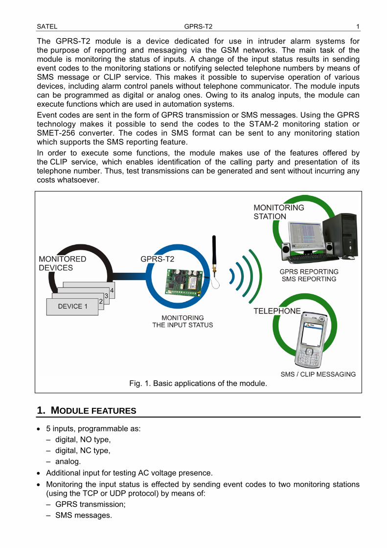
The GPRS-T2 module is a device dedicated for use in intruder alarm systems for the purpose of reporting and messaging via the GSM networks. The main task of the module is monitoring the status of inputs. A change of the input status results in sending event codes to the monitoring stations or notifying selected telephone numbers by means of SMS message or CLIP service. This makes it possible to supervise operation of various devices, including alarm control panels without telephone communicator. The module inputs can be programmed as digital or analog ones. Owing to its analog inputs, the module can execute functions which are used in automation systems.
Event codes are sent in the form of GPRS transmission or SMS messages. Using the GPRS technology makes it possible to send the codes to the STAM-2 monitoring station or SMET-256 converter. The codes in SMS format can be sent to any monitoring station which supports the SMS reporting feature.
In order to execute some functions, the module makes use of the features offered by the CLIP service, which enables identification of the calling party and presentation of its telephone number. Thus, test transmissions can be generated and sent without incurring any costs whatsoever.
Fig. 1. Basic applications of the module.
1. MODULE FEATURES
5 inputs, programmable as:
– digital, NO type,
– digital, NC type,
– analog.
Additional input for testing AC voltage presence.
Monitoring the input status is effected by sending event codes to two monitoring stations (using the TCP or UDP protocol) by means of:
– GPRS transmission;
– SMS messages.
2 GPRS-T2 SATEL
Capability to automatically replace the GPRS transmission with SMS message, if there are problems with GPRS transmission.
Encrypted transmission of events sent with the use of GPRS technology.
Notifying of a change in input status by means of: – SMS message;
– CLIP service.
Periodical test transmissions for checking availability of the module:
– to selected telephone numbers (with the use of SMS message or CLIP service);
– to monitoring stations.
Capability of generating additional test transmissions: – after identification of the calling party's telephone number (CLIP service);
– after receiving command from the GPRS-SOFT program.
Option to check the status of available resources and account validity of the SIM card installed in the module.
Indicator of GSM signal level received by industrial cellular telephone and an indicator of troubles connected with logging into the GSM network.
Relay output of NO type, controlled: – locally – by means of inputs;
– remotely – by means of SMS messages or CLIP.
OC type output for signaling problems with logging into the GSM network.
Module configuration: – locally – through the RS-232 (TTL) port;
– remotely – through the GSM network (GPRS technology);
– remotely – by means of SMS messages. Capability of remotely updating the module firmware by means of GPRS (units with built-in
GSM u-blox LEON-G100 telephone).
Ability to automatically restart the module.
Powered with 12 V DC (±15%).
2. DESCRIPTION OF ELECTRONICS BOARD
Description of terminals:
+12V - power supply input (12 V DC ±15%).
COM - common ground.
Z1 ÷ Z5 - module inputs. They can be programmed as digital (NC or NO type) or analog ones.
FT - OC type output, indicating a problem with logging into the GSM network. It activates approx. 2 minutes of the problem occurrence. When active, it is shorted to common ground and remains in this state until logging into GSM network. The problem with logging into the GSM network can be caused by: – unavailability of GSM network (out of range), – missing or damaged antenna, – entering an invalid PIN code, – missing SIM card,
Some additional information can be provided by LEDs on the electronics board (see: Fig. 3).
SATEL GPRS-T2 3
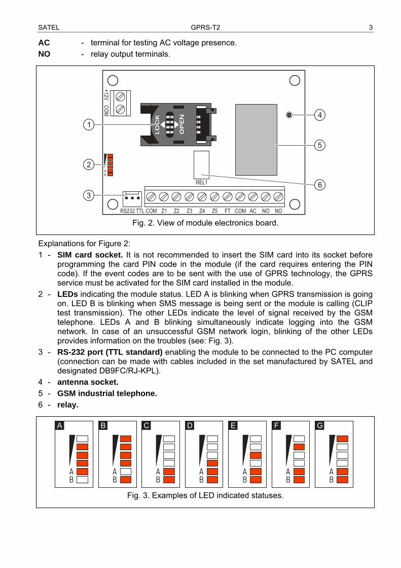
AC - terminal for testing AC voltage presence.
NO - relay output terminals.
Fig. 2. View of module electronics board.
Explanations for Figure 2:
1 - SIM card socket. It is not recommended to insert the SIM card into its socket before programming the card PIN code in the module (if the card requires entering the PIN code). If the event codes are to be sent with the use of GPRS technology, the GPRS service must be activated for the SIM card installed in the module.
2 - LEDs indicating the module status. LED A is blinking when GPRS transmission is going on. LED B is blinking when SMS message is being sent or the module is calling (CLIP test transmission). The other LEDs indicate the level of signal received by the GSM telephone. LEDs A and B blinking simultaneously indicate logging into the GSM network. In case of an unsuccessful GSM network login, blinking of the other LEDs provides information on the troubles (see: Fig. 3).
3 - RS-232 port (TTL standard) enabling the module to be connected to the PC computer (connection can be made with cables included in the set manufactured by SATEL and designated DB9FC/RJ-KPL).
4 - antenna socket.
5 - GSM industrial telephone.
6 - relay.
Fig. 3. Examples of LED indicated statuses.
4 GPRS-T2 SATEL
Explanations for Figure 3:
A (LED A is blinking, the other LEDs are lit up) – GPRS transmission is going on; signal level: 3.
B (LED B is blinking, the other LEDs are lit up) – SMS message is being sent or module is calling (CLIP test transmission); signal level: 4.
C (LEDs are blinking) – logging into GSM network.
D (LEDs are blinking) – logging into GSM network has failed; missing SIM card.
E (LEDs are blinking) – logging into GSM network has failed; missing PIN code.
F (LEDs are blinking) – logging into GSM network has failed; invalid PIN code.
G (LEDs are blinking) – logging into GSM network has failed; SIM card has been blocked after three attempts to use an invalid PIN code (PUK code must be used to unblock the SIM card).
3. INSTALLATION
Disconnect power before making any electrical connections.
It is not recommended to power up the device with disconnected antenna.
The GPRS-T2 module should be installed indoors, in spaces with normal air humidity. When selecting the installation place, take into consideration that thick walls, metal partitions, etc. will reduce the radio signal range. Installation in close vicinity of electrical systems is not recommended, as it may adversely affect the device performance.
The module power supply source should provide sufficient output current and be equipped with a battery.
The following installation procedure is recommended:
1. Connect the antenna to the socket on electronics board. Be careful not to damage the socket.
2. Connect the devices whose operation is to be monitored by the module to the input terminals, as required.
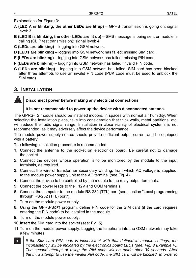
3. Connect the wire of transformer secondary winding, from which AC voltage is supplied, to the module power supply unit to the AC terminal (see Fig. 4).
4. Connect the device to be controlled by the module to the relay output terminals.
5. Connect the power leads to the +12V and COM terminals.
6. Connect the computer to the module RS-232 (TTL) port (see: section "Local programming through RS-232 (TTL) port").
7. Turn on the module power supply.
8. Using the GPRS-SOFT program, define PIN code for the SIM card (if the card requires entering the PIN code) to be installed in the module.
9. Turn off the module power supply.
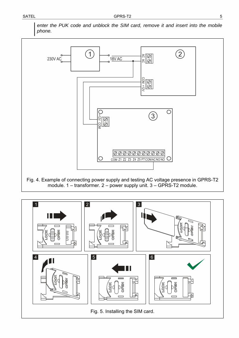
10. Insert the SIM card into the socket (see: Fig. 5).
11. Turn on the module power supply. Logging the telephone into the GSM network may take a few minutes.
If the SIM card PIN code is inconsistent with that defined in module settings, the inconsistency will be indicated by the electronics board LEDs (see: Fig. 3 Example F). The second attempt of using the PIN code will be made after 30 seconds. After the third attempt to use the invalid PIN code, the SIM card will be blocked. In order to
SATEL GPRS-T2 5
enter the PUK code and unblock the SIM card, remove it and insert into the mobile phone.
Fig. 4. Example of connecting power supply and testing AC voltage presence in GPRS-T2
module. 1 – transformer. 2 – power supply unit. 3 – GPRS-T2 module.
Fig. 5. Installing the SIM card.
6 GPRS-T2 SATEL
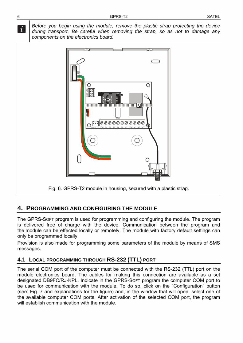
Before you begin using the module, remove the plastic strap protecting the device during transport. Be careful when removing the strap, so as not to damage any components on the electronics board.
Fig. 6. GPRS-T2 module in housing, secured with a plastic strap.
4. PROGRAMMING AND CONFIGURING THE MODULE
The GPRS-SOFT program is used for programming and configuring the module. The program is delivered free of charge with the device. Communication between the program and the module can be effected locally or remotely. The module with factory default settings can only be programmed locally.
Provision is also made for programming some parameters of the module by means of SMS messages.
4.1 LOCAL PROGRAMMING THROUGH RS-232 (TTL) PORT
The serial COM port of the computer must be connected with the RS-232 (TTL) port on the module electronics board. The cables for making this connection are available as a set designated DB9FC/RJ-KPL. Indicate in the GPRS-SOFT program the computer COM port to be used for communication with the module. To do so, click on the "Configuration" button (see: Fig. 7 and explanations for the figure) and, in the window that will open, select one of the available computer COM ports. After activation of the selected COM port, the program will establish communication with the module.
SATEL GPRS-T2 7
4.2 REMOTE PROGRAMMING USING GPRS TECHNOLOGY
During the remote programming of the module, all functions that require the use of GSM telephone will be disabled.
Remote programming is possible when the "Remote programming" option is enabled in the module and the following items have been programmed:
– PIN code (if the card requires entering the PIN code);
– Access Point Name (APN) for Internet GPRS connection;
– user name for Internet GPRS connection;
– password for Internet GPRS connection;
– DNS server IP address which is to be used by the module (the DNS server address requires no programming, if the computer address is entered as IP address);
– initialization code for computer connection.
APN, user name, password and DNS server address can be obtained from the GSM network operator.
The computer on which the GPRS-SOFT program will be running must have its IP address visible in the Internet (so-called public IP address). Otherwise, the network server port must be redirected to that computer, so as to make connection with the computer possible.
In order to establish communication between the module and the computer, do the following:
1. Start the GPRS-SOFT program.
2. Click on the "Configuration" button (see: Fig. 7 and explanations for the figure) and, in the window that will open, enter the number of TCP port selected for communication with the module. The number will have to be included in the body of SMS message which will be sent to the module GSM telephone number to initialize communication.
3. Click on the button (see Fig. 7). In the menu that will open, select "TCP/IP" to activate the server.
4. Send SMS message to the module GSM telephone number. The SMS message should have the following form: xxxx=aaaa:p= ("xxxx" is the module defined code to initialize communication with GPRS-SOFT program – "Initiating SMS"; "aaaa" is the address of the computer with which the module is to establish communication, shown numerically or as a name; "p" stands for the number of network port through which communication with the GPRS-SOFT program is to be effected). The module will connect to the computer whose address was given in the SMS message.
8 GPRS-T2 SATEL
4.3 DESCRIPTION OF THE PROGRAM
4.3.1 MAIN MENU
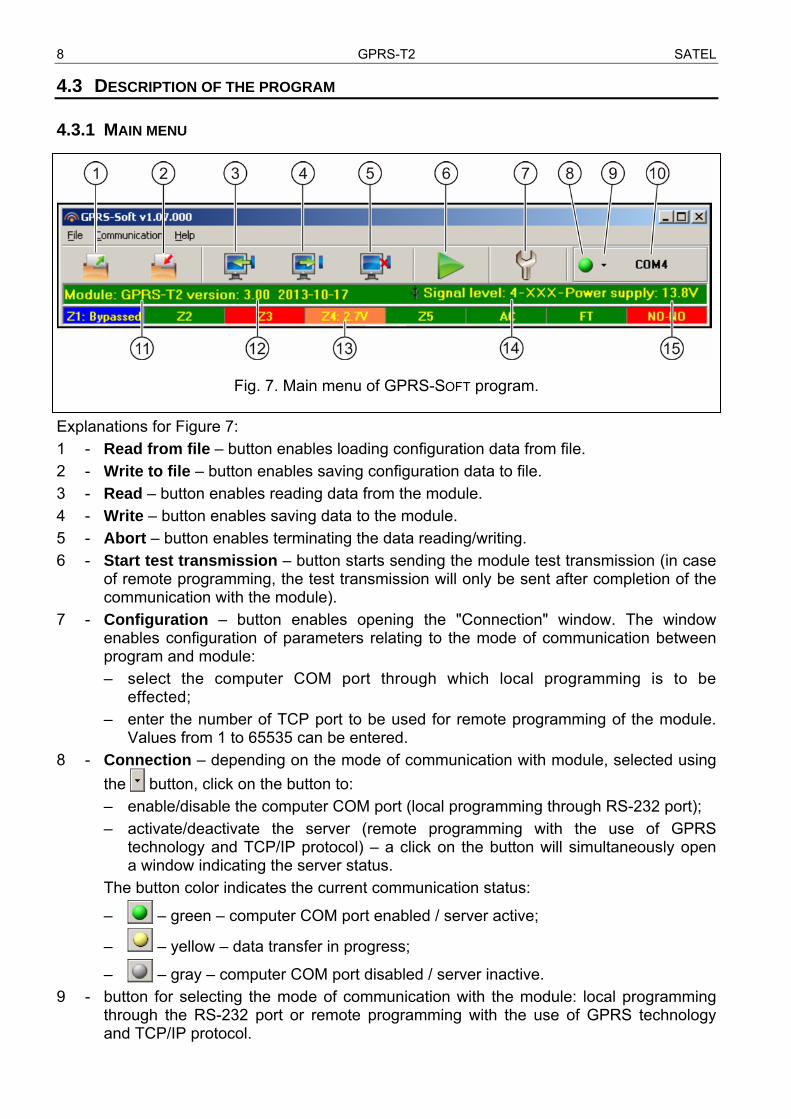
Fig. 7. Main menu of GPRS-SOFT program.
Explanations for Figure 7:
1 - Read from file – button enables loading configuration data from file.
2 - Write to file – button enables saving configuration data to file.
3 - Read – button enables reading data from the module.
4 - Write – button enables saving data to the module.
5 - Abort – button enables terminating the data reading/writing.
6 - Start test transmission – button starts sending the module test transmission (in case of remote programming, the test transmission will only be sent after completion of the communication with the module).
7 - Configuration – button enables opening the "Connection" window. The window enables configuration of parameters relating to the mode of communication between program and module:
– select the computer COM port through which local programming is to be effected;
– enter the number of TCP port to be used for remote programming of the module. Values from 1 to 65535 can be entered.
8 - Connection – depending on the mode of communication with module, selected using
the button, click on the button to:
– enable/disable the computer COM port (local programming through RS-232 port);
– activate/deactivate the server (remote programming with the use of GPRS technology and TCP/IP protocol) – a click on the button will simultaneously open a window indicating the server status.
The button color indicates the current communication status:
– – green – computer COM port enabled / server active;
– – yellow – data transfer in progress;
– – gray – computer COM port disabled / server inactive. 9 - button for selecting the mode of communication with the module: local programming
through the RS-232 port or remote programming with the use of GPRS technology and TCP/IP protocol.
SATEL GPRS-T2 9
10 - information on the mode of communicating with the module:
– COMn (n = COM port number) – communication through the RS-232 port;
– TCP/IP – communication with the use of GPRS technology.
11 - module name.
12 - version of module program (version number and build date).
13 - status bar showing the status of all inputs and outputs of the module. Individual colors indicate the following states:
green – normal input status / output turned off,
blue – blocked input,
red – digital input violated / voltage has exceeded the value preset for threshold H of analog input / output turned on,
orange – voltage has dropped below the value preset for threshold L of analog input,
gray – input disabled. 14 - level of signal received by the GSM antenna and the name of service provider used by
the module. If the module telephone has failed to log into the GSM network, the icon will be displayed here to indicate trouble.
15 - current level of module supply voltage.
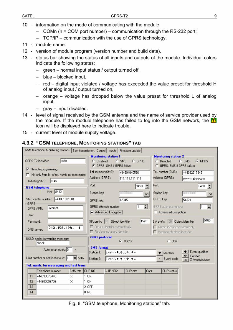
4.3.2 “GSM TELEPHONE, MONITORING STATIONS” TAB
Fig. 8. “GSM telephone, Monitoring stations” tab.
10 GPRS-T2 SATEL
Programming GPRS-T2 identifier – a sequence of 1 to 8 alphanumeric characters to identify the module.
Communication between the program and the module is only possible when the identifier entered in this field is consistent with that stored in the module. No identifier is preprogrammed in the module with factory default settings. Communication with such a module can be established without entering any identifier in the program, but as soon as the connection is established, the program will automatically generate a random identifier. It can be saved into the module or enter another one and save it.
Remote programming – enable this option if remote programming of the module with the use of GPRS technology is to be available.
Initiating number only from list of telephone numbers for messaging – if this option is enabled, the SMS message initiating the remote programming must be sent from a telephone whose number is stored in the module memory in the list of telephone numbers for messaging.
Initiating SMS – a code which must be included in the SMS message sent to the module GSM telephone number, so that the module can make an attempt to connect to the computer whose IP address and communication port are indicated in the SMS message.
GSM telephone PIN – SIM card PIN code (if the card requires entering the PIN code).
Entering invalid PIN code may result in blocking the SIM card.
SMS center number – telephone number of the Short Message Service Center, which delivers SMS messages. If the number has been written by the operator to the memory of SIM card installed in the device, it need not be entered. In such a situation, the module will download it automatically. Otherwise, it is necessary to enter the number, if the module is to send SMS messages. It should be remembered that the number written into the module must be suitable for the network in which the SIM card is registered.
GPRS APN – Access Point Name for Internet GPRS connection.
User – user name for Internet GPRS connection.
Password – password for Internet GPRS connection.
APN, user name and password must be defined, if GPRS data transmission (event codes, programming) is to be available.
DNS server – DNS server IP address which is to be used by the module. The DNS server address is necessary when GPRS technology is used for sending data, if the address of the device to which the module is to connect (monitoring station, computer with GPRS-SOFT program) has been entered as a name. If all addresses are given in the IP address form (4 decimal numbers separated by dots), programming the DNS server address is not required.
Other
USSD codes forwarding message – content of the control command that must precede the USSD code in SMS message being sent to the module. The USSD codes make it possible e.g. to check the account status of SIM card installed in the module. The form of SMS message must be: xxxx=yyyy=, where “xxxx” is the control command, and “yyyy” – the USSD code served by the operator of GSM network in which the telephone is used (it depends on the SIM card installed in the module). Having received such an SMS message, the module will execute the USSD code contained therein. The answer received from the operator is sent in the form of SMS message to the telephone number from which the control command was sent.
SATEL GPRS-T2 11
Using the advanced functions available due to the USSD service (when menu is presented in reply to the code entered) is not recommended.
Autorestart every – if the restart of module settings is to be periodically repeated, you must define every how many hours it is to happen. The first restart of module settings will occur after the programmed time has elapsed since the settings were written to the module. If 0 is entered, the function will be disabled.
Limit number of notifications to – this field allows you to specify the maximum number of transmissions (GPRS, SMS messages, CLIP service) sent by the module during 24 hours. The test transmissions and SMS messages with information on module status are not included in the number of transmissions and are not limited. Values from 0 to 255 can be entered. Entering 0 means no transmission limit (default: 0).
Monitoring station 1 / Monitoring station 2
Using GPRS technology, event codes can be sent to the STAM-2 monitoring station or to the SMET-256 converter.
Communication with the subscriber sending event codes with the use of GPRS technology should be tested by the monitoring station as rarely as possible (if a value lower than 1 minute is entered in the “Test period” field of the monitoring station, the time will be rounded up by the module to 1 minute). It is recommended that the maximum value be set, i.e. 255 seconds.
Disabled – if this option is selected, event codes will not be sent to the monitoring station.
SMS – if this option is selected, event codes will be sent to the monitoring station in the form of SMS messages.
GPRS – if this option is selected, event codes will be sent to the monitoring station with the use of GPRS technology.
GPRS, SMS if GPRS failure – if this option is selected, event codes will be sent to the monitoring station with the use of GPRS technology, but after a specified number of failed attempts to send events (lack of receipt acknowledgement from the monitoring station), the event code will be sent in the form of SMS message.
Tel. number (SMS) – GSM telephone number used by the monitoring station for receiving SMS messages. Must be preceded by the country code.
Address (GPRS) – address of the monitoring station. It can be entered in the IP address form (4 decimal numbers separated by dots) or as a name.
Port – number of TCP port through which communication with the monitoring station will be effected. The port number must be the same as that programmed in the monitoring station.
Station key – enter in this field a string of 1 to 12 alphanumeric characters (digits, letters and special characters) which define the key for coding the data to be sent to the monitoring station. It must be consistent with that defined in the monitoring station for managing subscribers in the simple mode.
GPRS key – a string of 1 do 5 alphanumeric characters identifying the module. It must be consistent with that defined in the monitoring station (“ETHM/GPRS key”).
GPRS attempts number – the number of failed attempts to send the event code to the monitoring station using the GPRS technology, after which the module will made an attempt to send the event code in the form of SMS message. The field is available if the “GPRS, SMS if GPRS failure” field is selected. You can enter values from 1 to 16 (default: 1).
Advanced encryption – enabling this option will increase the security level of data transmitted to the monitoring station. This option requires a SMET-256 converter with
12 GPRS-T2 SATEL
firmware version 1.06 or higher, or STAM-1 PE and STAM-1 RE cards, version 3.03 or higher.
Object identifier – enter in this field 4 characters (digits or letters from A to F) which will serve as an identifier during the test transmissions sent by the module. Do not enter value 0000 (the module will not be sending test transmissions to the monitoring station). Using digit 0 in the identifier is not recommended.
GPRS reporting TCP / IP – if this field is selected, the module will send event codes to the monitoring station
using the TCP protocol.
UDP – if this field is selected, the event codes will be sent to the monitoring station by the module using the UDP protocol.
SMS format The format of SMS messages for SMS reporting must be defined according to the monitoring station requirements. The default SMS messages format programmed in the module corresponds to the factory default settings of the STAM-2 monitoring station (program version1.2.0 or later). If events are to be sent in the form of two characters, enter the partition symbol only.
Telephone numbers for messaging and test transmissions Telephone number – you can program 4 telephone numbers, to which the module can send
SMS messages and test transmissions, and which can also be used to control the output with the CLIP. The telephone number must be preceded by the country dialing code.
SMS retr. – select this field (which is selected when the "x" symbol is shown in it), if the SMS messages received by the module and sent from the phone numbers which are not on the list (e.g. information received from the operator of the GSM network in which the module is used) are to be forwarded to the given phone number.
CLIP-NO1 – you can define in this field if and how the output can be controlled from the selected telephone number (T1 – T4), using the CLIP. You can choose from the following options:
0: NO – CLIP does not control the output,
1: ON – CLIP will activate the output,
2: OFF – CLIP will deactivate the output,
3: ON for a time – CLIP will activate the output for a period of time (the time is defined in the “Output cut-off time” field, “Test transmission, Control” tab).
4.3.3 “TEST TRANSMISSION, CONTROL” TAB
Test transmissions
The module test transmissions may be sent periodically at defined time intervals, and also can be generated after identification of the telephone number of the calling party (CLIP service) or after receiving a command from the GPRS-SOFT program. The test transmission can have a form of SMS message sent to the selected telephone numbers, can be realized with the use of CLIP service to the selected telephone numbers or can be sent in the form of event code to the monitoring station.
Test transmission every – if the module test transmission is to be of periodical nature, you have to program every how many days, hours and minutes it should be sent. The first test transmission will be sent after the preset time since saving the settings in the module has elapsed.
SATEL GPRS-T2 13
If an extra test transmission (using the CLIP service or the GPRS-SOFT program command) is generated, the time before sending the periodical test transmission will be counted from the beginning.
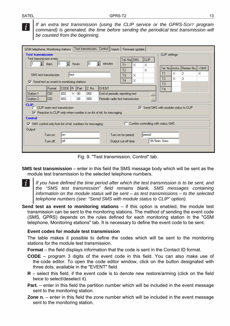
Fig. 9. "Test transmission, Control" tab.
SMS test transmission – enter in this field the SMS message body which will be sent as the
module test transmission to the selected telephone numbers.
If you have defined the time period after which the test transmission is to be sent, and the “SMS test transmission” field remains blank, SMS messages containing information on the module status will be sent – as test transmissions – to the selected telephone numbers (see: “Send SMS with module status to CLIP” option).
Send test as event to monitoring stations – if this option is enabled, the module test transmission can be sent to the monitoring stations. The method of sending the event code (SMS, GPRS) depends on the rules defined for each monitoring station in the "GSM telephone, Monitoring stations" tab. It is necessary to define the event code to be sent.
Event codes for module test transmission The table makes it possible to define the codes which will be sent to the monitoring stations for the module test transmission.
Format – the field displays information that the code is sent in the Contact ID format.
CODE – program 3 digits of the event code in this field. You can also make use of the code editor. To open the code editor window, click on the button designated with three dots, available in the "EVENT" field.
R – select this field, if the event code is to denote new restore/arming (click on the field twice to select/deselect it).
Part. – enter in this field the partition number which will be included in the event message sent to the monitoring station.
Zone n. – enter in this field the zone number which will be included in the event message sent to the monitoring station.
14 GPRS-T2 SATEL
EVENT – the field displays description of the event whose code is entered in the "CODE" field. A button designated with three dots, which opens the editor of Contact ID codes, is also available in the "EVENT" field.
The test transmission will be sent as an event, if the following parameters and options are programmed for the monitoring station:
GPRS reporting (see section “Starting GPRS reporting”) or SMS reporting (see section “Starting SMS reporting”) is activated,
object identifier different from "0000" is programmed,
reporting format is programmed,
event code different from "000" is programmed.
Test transmissions to be sent to telephone numbers The table allows you to define the form in which the test transmissions will be sent to the telephone numbers programmed in the “GSM telephone, Monitoring stations” tab. Click twice on the chosen field to select/deselect it (the field is selected if the “x” symbol is displayed in it).
SMS – select this field, if the module test transmission is to be sent to the selected telephone number in the form of SMS message.
CLIP – select this field, if the module test transmission for the selected telephone number is to be realized with the use of CLIP service (the module will dial the programmed number and then will be trying for 30 seconds to get through – the module telephone number will be displayed in the telephone).
Do not answer any call from the module, if the CLIP test transmission is to be effected without incurring any costs.
CLIP settings The table makes it possible to determine in detail how the CLIP test transmissions are to be sent to the four telephone numbers programmed in the “GSM telephone, Monitoring stations” tab. Click twice on the chosen field to select/deselect it (the field is selected, if “x” symbol is displayed in it).
Acknowledgement – select this field if the module is to wait for the acknowledgement of receipt of test transmission using the CLIP service. In order to acknowledge receiving the CLIP test transmission, reject the call coming from the module.
Retries number – if the “Acknowledgement” field is selected, the test transmission with the use of CLIP service can be conducted a specified number of times. Values from 1 to 15 can be programmed. Acknowledgement of the CLIP test transmission receipt will make the module stop repeating such a transmission (e.g. if the test transmission is programmed to be repeated 5 times, but it is already received at the first attempt, the module will not send the other 4 transmissions).
-> SMS – if the “Acknowledgement” field is selected and receiving the CLIP test transmission is not acknowledged, the module may send a “CLIP failed” SMS message to the selected telephone number.
CLIP
CLIP starts test transmission – if this option is enabled, it is possible to send a test transmission with the use of CLIP service. Call the module telephone number and after hearing the dialing tone, hang up – the module will identify the telephone number of the calling party and send a test transmission according to the preprogrammed settings.
Send SMS with module status to CLIP – if this option is enabled, it is possible to obtain information about the module status with the use of CLIP service. Call the module
SATEL GPRS-T2 15
telephone number and after hearing the dialing tone, hang up – the module will identify the telephone number of the calling party and send to that number an SMS message containing the following information:
– module name;
– version of module software (version number and date of build);
– S0 ÷ S4 – current level of signal received by the antenna;
– P – current supply voltage value.
– Z1 ÷ Z5 – information on the status of Z1 ÷ Z5 inputs:
i – digital / analog input normal status,
I – digital input violated,
L – voltage at analog input has dropped below threshold L; information on input voltage value,
H – voltage at analog input has exceeded threshold H; information on input voltage value,
b – digital / analog input blocked.
– AC – information on AC input status:
i – AC voltage presence,
I – AC voltage loss.
– OUT – information on relay output status:
o – output inactive,
O – output active.
– EVb – the maximum number of transmissions has been reached (see the “Limit number of notifications to” parameter in the “GSM telephone, Monitoring stations” tab).
Reaction to CLIP only when number is on list of telephones for messaging – if this option is enabled, the module will only send test transmission or SMS message with status information when the telephone number, identified owing to the CLIP service, is one of the numbers programmed in the “GSM telephone, Monitoring stations” tab on the “Telephone numbers for messaging and test transmissions” list.
If the “Reaction to CLIP only when number is on list of telephones for messaging” option is not enabled, the test transmissions and SMS messages with information on device status:
for the numbers in the list, they will be sent by the module immediately,
for the numbers not in the list, they can be sent by the module every 10 minutes at the most.
Control
The output and inputs can be controlled by means of SMS messages.
Control SMS control only from list of telephone numbers for messaging – if this option is
enabled, the functions of enabling, disabling or time-enabling the relay output, as well as blocking/unblocking the inputs will only take effect after the SMS message is sent from a telephone number which is programmed in the “GSM telephone, Monitoring stations” tab in the “Telephone numbers for messaging and test transmissions”.
Confirm controlling with status SMS – if this option is enabled, starting the functions of turning on, turning off or turning on for a period the relay output, as well as blocking/unblocking the inputs will result in sending by the module of an SMS message
16 GPRS-T2 SATEL
containing information on the module status to the telephone number from which the control message was sent (see: “Send SMS with module status to CLIP” option).
Output Turn on – enter in this field the SMS message content that will be sent to the module
telephone number in order to activate the relay output.
Turn off – enter in this field the SMS message content that will be sent to the module telephone number in order to deactivate the relay output.
Turn on for period – enter in this field the SMS message content that will be sent to the module telephone number in order to activate the relay output for a defined period of time.
Output cut-off time – if the relay output is to be activated for a period of time, the time must be defined. After the time runs out, the output will be deactivated. You can program times up to 18 hours 12 minutes and 15 seconds. If the output cut-off time is not programmed, activating the output for a period of time will be impossible.
The body of SMS messages for starting the functions of turn on, turn off or turn on for time the relay output may contain up to 24 characters.
4.3.4 “INPUTS” TAB
Inputs The table enables programming the working parameters of Z1 ÷ Z5 inputs and AC input.
For the AC input, it is only possible to program the “Sensitivity” parameter (values up to 99 minutes and 59 seconds can be entered) and define whether and how it is to control the output.
Type – the input can be programmed as:
– digital, NC type – enter digit 1,
– digital, NO type – enter digit 2,
– analog – enter digit 3,
– disabled – enter digit 0.
Sensitivity – time during which:
– the NC type digital input must be disconnected from the ground so that the module can register the input violation,
– the NO type digital input must be shorted to ground so that the module can register the input violation,
– voltage on the analog input must drop below threshold L (minus tolerance) or rise above threshold H (plus tolerance) so that the module can register exceeding the preset value (see Fig. 11).
Values from the 0 to 5100 ms range can be programmed (every 20 ms).
Restore – time during which:
– the NC type digital input must be again shorted to ground so that the module can register input restore,
– the NO type digital input must be again disconnected from the ground so that the module can register input restore,
– voltage on the analog input must rise above threshold L (plus tolerance) or drop below threshold H (minus tolerance) so that the module can register input restore.
The defined time makes it possible to reduce the number of sent transmissions. Values from the 0 to 255 seconds range can be programmed.
SATEL GPRS-T2 17
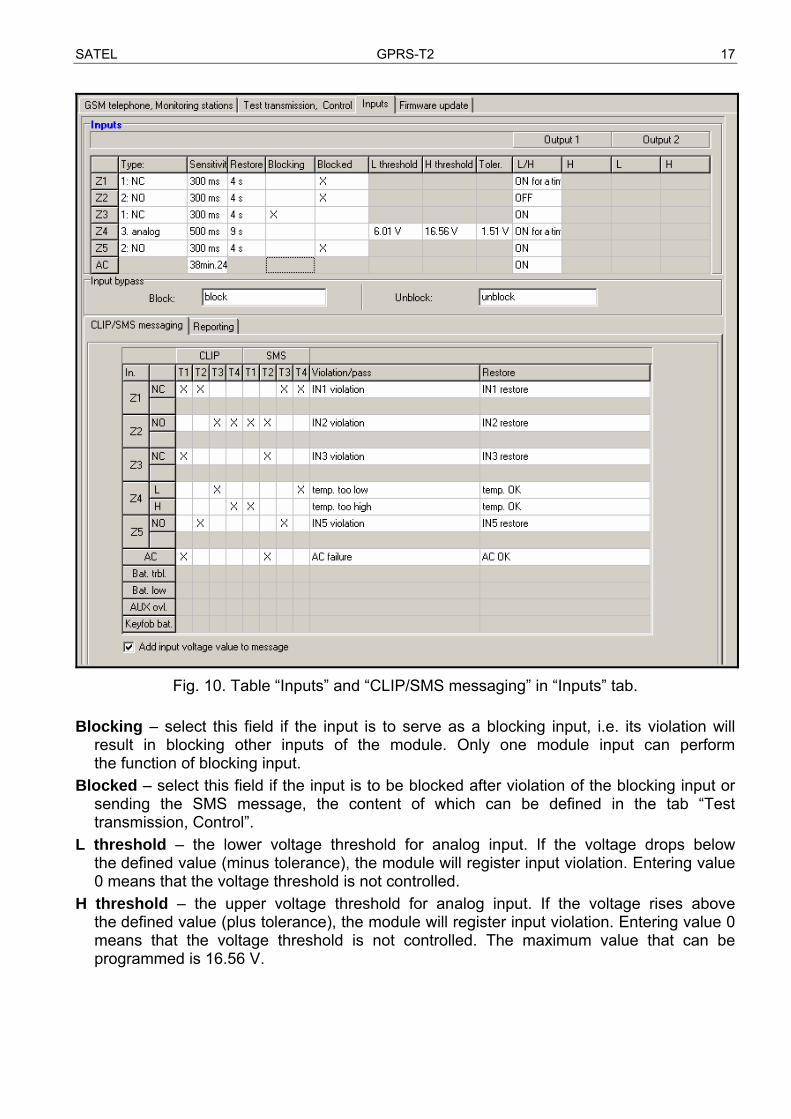
Fig. 10. Table “Inputs” and “CLIP/SMS messaging” in “Inputs” tab.
Blocking – select this field if the input is to serve as a blocking input, i.e. its violation will
result in blocking other inputs of the module. Only one module input can perform the function of blocking input.
Blocked – select this field if the input is to be blocked after violation of the blocking input or sending the SMS message, the content of which can be defined in the tab “Test transmission, Control”.
L threshold – the lower voltage threshold for analog input. If the voltage drops below the defined value (minus tolerance), the module will register input violation. Entering value 0 means that the voltage threshold is not controlled.
H threshold – the upper voltage threshold for analog input. If the voltage rises above the defined value (plus tolerance), the module will register input violation. Entering value 0 means that the voltage threshold is not controlled. The maximum value that can be programmed is 16.56 V.
18 GPRS-T2 SATEL
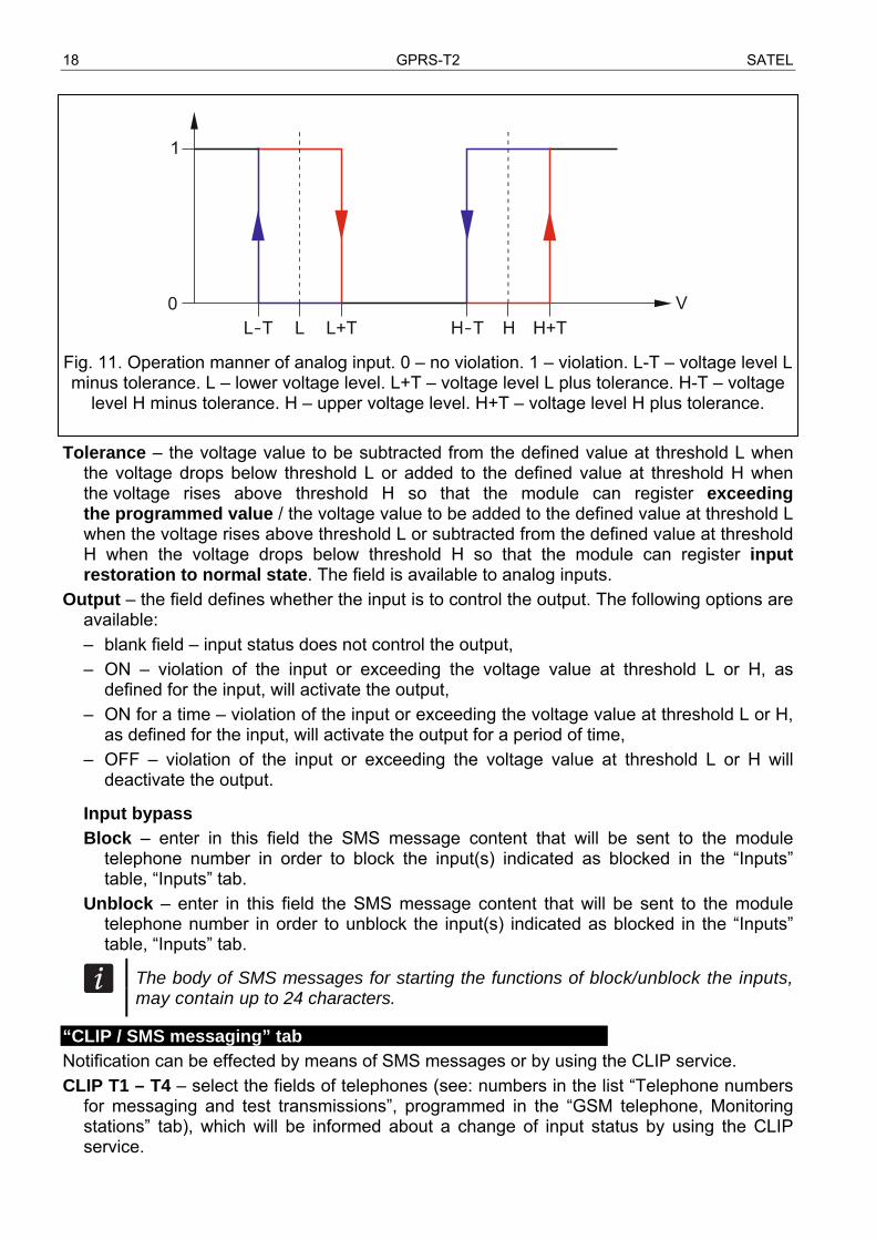
Fig. 11. Operation manner of analog input. 0 – no violation. 1 – violation. L-T – voltage level L minus tolerance. L – lower voltage level. L+T – voltage level L plus tolerance. H-T – voltage
level H minus tolerance. H – upper voltage level. H+T – voltage level H plus tolerance.
Tolerance – the voltage value to be subtracted from the defined value at threshold L when
the voltage drops below threshold L or added to the defined value at threshold H when the voltage rises above threshold H so that the module can register exceeding the programmed value / the voltage value to be added to the defined value at threshold L when the voltage rises above threshold L or subtracted from the defined value at threshold H when the voltage drops below threshold H so that the module can register input restoration to normal state. The field is available to analog inputs.
Output – the field defines whether the input is to control the output. The following options are available:
– blank field – input status does not control the output,
– ON – violation of the input or exceeding the voltage value at threshold L or H, as defined for the input, will activate the output,
– ON for a time – violation of the input or exceeding the voltage value at threshold L or H, as defined for the input, will activate the output for a period of time,
– OFF – violation of the input or exceeding the voltage value at threshold L or H will deactivate the output.
Input bypass Block – enter in this field the SMS message content that will be sent to the module
telephone number in order to block the input(s) indicated as blocked in the “Inputs” table, “Inputs” tab.
Unblock – enter in this field the SMS message content that will be sent to the module telephone number in order to unblock the input(s) indicated as blocked in the “Inputs” table, “Inputs” tab.
The body of SMS messages for starting the functions of block/unblock the inputs, may contain up to 24 characters.
“CLIP / SMS messaging” tab Notification can be effected by means of SMS messages or by using the CLIP service.
CLIP T1 – T4 – select the fields of telephones (see: numbers in the list “Telephone numbers for messaging and test transmissions”, programmed in the “GSM telephone, Monitoring stations” tab), which will be informed about a change of input status by using the CLIP service.
SATEL GPRS-T2 19
SMS T1 – T4 – select the fields of telephones (see: numbers in the list “Telephone numbers for messaging and test transmissions”, preprogrammed in the “GSM telephone, Monitoring stations” tab), to which an SMS message is to be sent to notify about a change of input status.
Violation/pass – content of the SMS message that will be sent on the input violation / exceeding the preprogrammed input voltage value (rise above the defined value at threshold H or drop below the defined value at threshold L). The message may consist of up to 24 characters. It may not contain any diacritical characters. If the field is left blank, the message will not be sent.
Restore – content of the SMS message that will be sent on the input restore. The message may consist of up to 24 characters. It may not contain any diacritical characters. If the field is left blank, the message will not be sent.
Add input voltage value to message – if this option is enabled, information on the current voltage value at the input will be added to the SMS message about the analog input status.
For the analog inputs, the messaging parameters are to be defined separately for each of the defined thresholds.
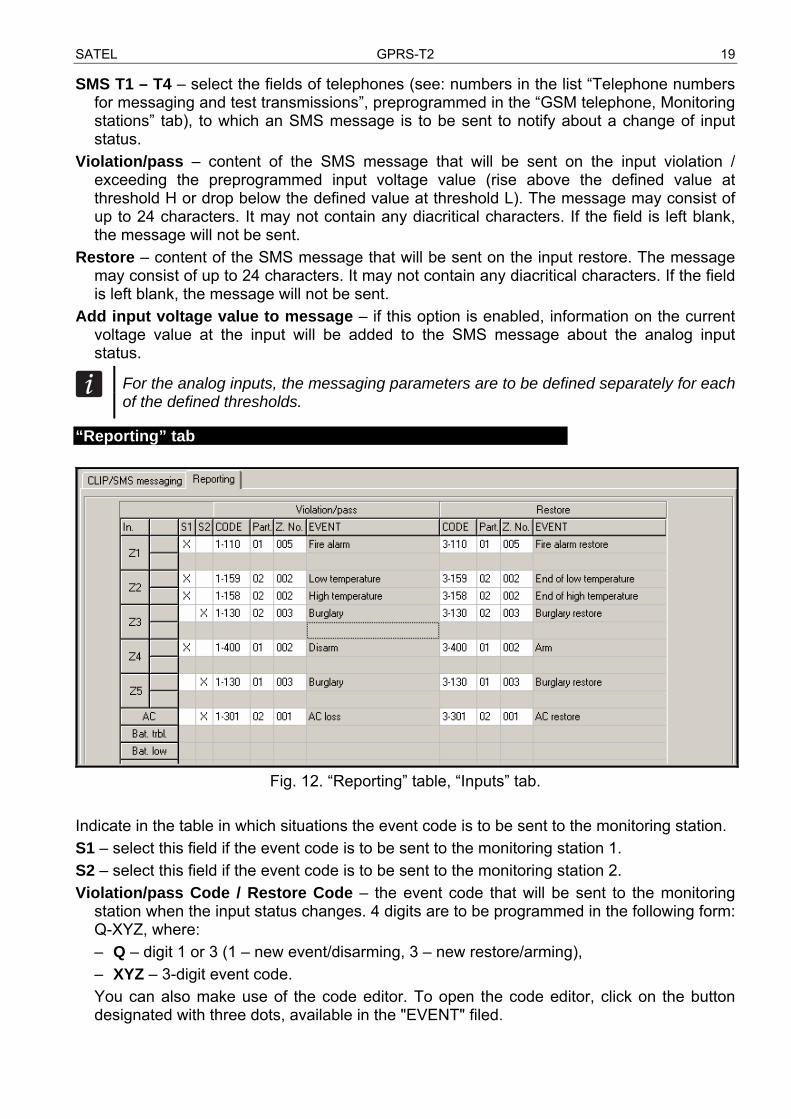
“Reporting” tab
Fig. 12. “Reporting” table, “Inputs” tab.
Indicate in the table in which situations the event code is to be sent to the monitoring station.
S1 – select this field if the event code is to be sent to the monitoring station 1.
S2 – select this field if the event code is to be sent to the monitoring station 2.
Violation/pass Code / Restore Code – the event code that will be sent to the monitoring station when the input status changes. 4 digits are to be programmed in the following form: Q-XYZ, where:
– Q – digit 1 or 3 (1 – new event/disarming, 3 – new restore/arming),
– XYZ – 3-digit event code.
You can also make use of the code editor. To open the code editor, click on the button designated with three dots, available in the "EVENT" filed.
20 GPRS-T2 SATEL
Violation/pass Partition / Restore Partition – partition number which will be sent in the event code. You can enter numbers and letters from A to F.
If events are to be sent in the form of two characters (partition number only), you should not use the code editor.
Violation/pass Zone n. / Restore Zone n. – zone / module / user number which will be sent in the event code.
Violation/pass Event / Restore Event – this field displays description of the event, whose code is entered in the "CODE" field. Available in the "EVENT" field is also the button designated with three dots, which enables opening of the code editor.
For the analog inputs, the reporting related parameters are to be determined separately for each of the defined thresholds.
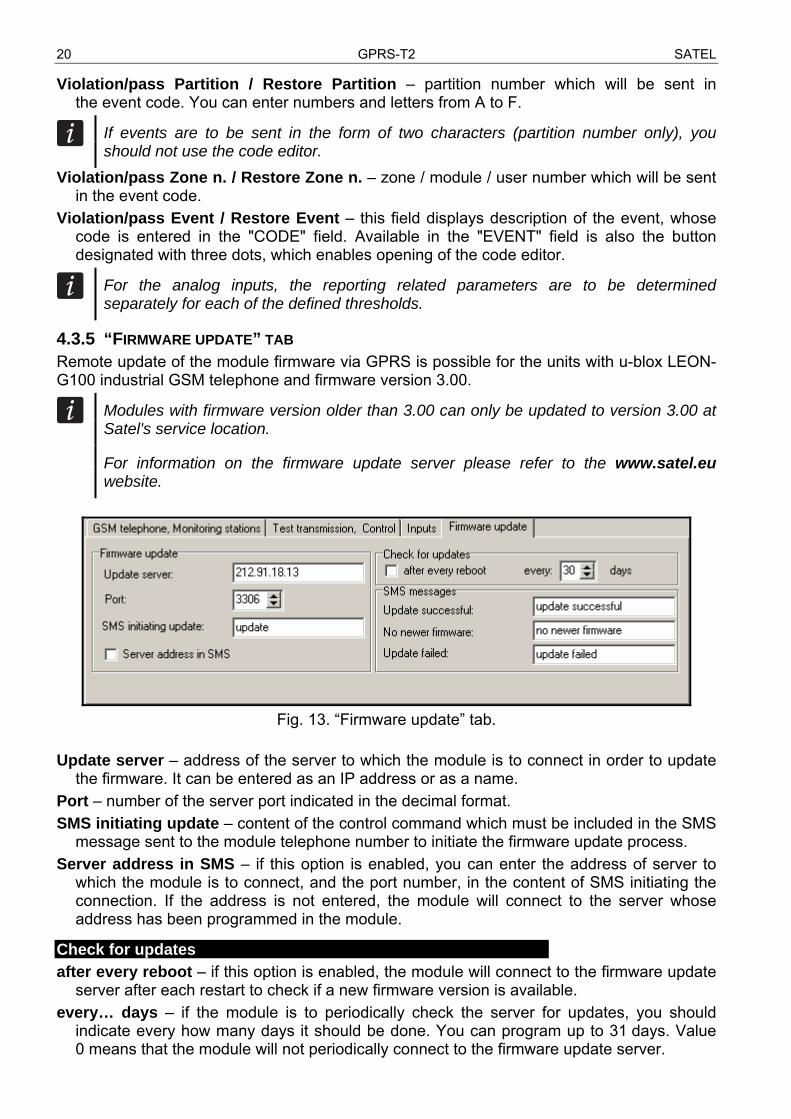
4.3.5 “FIRMWARE UPDATE” TAB Remote update of the module firmware via GPRS is possible for the units with u-blox LEON-G100 industrial GSM telephone and firmware version 3.00.
Modules with firmware version older than 3.00 can only be updated to version 3.00 at Satel's service location.
For information on the firmware update server please refer to the www.satel.eu website.
Fig. 13. “Firmware update” tab.
Update server – address of the server to which the module is to connect in order to update
the firmware. It can be entered as an IP address or as a name.
Port – number of the server port indicated in the decimal format.
SMS initiating update – content of the control command which must be included in the SMS message sent to the module telephone number to initiate the firmware update process.
Server address in SMS – if this option is enabled, you can enter the address of server to which the module is to connect, and the port number, in the content of SMS initiating the connection. If the address is not entered, the module will connect to the server whose address has been programmed in the module.
Check for updates after every reboot – if this option is enabled, the module will connect to the firmware update
server after each restart to check if a new firmware version is available.
every… days – if the module is to periodically check the server for updates, you should indicate every how many days it should be done. You can program up to 31 days. Value 0 means that the module will not periodically connect to the firmware update server.
SATEL GPRS-T2 21
SMS messages Update successful – SMS message which will be sent after the process of module firmware
update has been finished successfully.
No newer firmware – SMS message which will be sent after the module has checked that no newer firmware is available.
Update failed – SMS message which will be sent after an unsuccessful attempt to update the module firmware.
The SMS messages with information on results of the update may contain up to 32 characters.
4.4 PROGRAMMING BY MEANS OF SMS MESSAGES
You can program the module using SMS messages:
at any moment from the telephone whose number is programmed in the “Telephone numbers for messaging and test transmissions” list, “GSM telephone, Monitoring stations” tab;
during 15 minutes after module start from any telephone. After receipt of the SMS programming message, the programming mode will be extended each time by 15 minutes, counting from the moment of receiving the message.
Using the SMS messages you can:
1. Add phone numbers to the "Telephone numbers for messaging and test transmissions" list (“GSM telephone, Monitoring stations” tab in the GPRS-Soft program) by sending:
“SET1=+48XXXXXXXXX=” - to add the phone number T1,
“SET2=+48XXXXXXXXX=” - to add the phone number T2,
“SET3=+48XXXXXXXXX=” - to add the phone number T3, “SET4=+48XXXXXXXXX=” - to add the phone number T4,
where the XXXXXXXXX characters denote digits of the number to be added.
2. Delete phone numbers from the “Telephone numbers for messaging and test transmissions” list by sending:
“DEL1” – to delete the phone number T1,
“DEL2” – to delete the phone number T2,
“DEL3” – to delete the phone number T3,
“DEL4” – to delete the phone number T4.
3. Delete all phone numbers from the “Telephone numbers for messaging and test transmissions” list, sending “DELALL”.
4. Reset the number of transmissions sent by the module, sending “RESET” (see the “Limit number of notifications to” parameter, “GSM telephone, Monitoring stations” tab, in the GPRS-Soft program). Having received this message, the module will start anew the count of sent transmissions.
The module is case-sensitive, hence the content of SMS messages for programming the module settings should be entered in upper-case letters.
4.5 STARTING GPRS REPORTING
1. Enter the GPRS communication parameters (“GSM telephone, Monitoring stations” tab):
– Access Point Name (APN) for Internet GPRS connection;
– user name for Internet GPRS connection;
22 GPRS-T2 SATEL
– password for Internet GPRS connection;
– DNS server IP address which is to be used by the module (the DNS server address requires no programming, if the IP address is entered for the monitoring station).
2. Configure parameters of the monitoring station(s) (“GSM telephone, Monitoring stations” tab):
– select the “GPRS” option;
– enter the monitoring station address (“Address (GPRS)” field);
– enter the number of TCP port through which communication with the monitoring station will be effected;
– enter the encryption key for data to be sent to the monitoring station (“Station key”);
– enter the GPRS key.
3. Define the protocol to be used by the module for sending event codes to the monitoring station (“TCP/IP” and “UDP” fields).
4. Determine the operation mode for the inputs, the status of which is to be monitored ("Inputs" tab):
– define the input type (digital of NO or NC type or analog);
– define the “Sensitivity” and “Restore” parameters for the inputs (for the AC input only the “Sensitivity” parameter);
– define additionally the “L threshold”, “H threshold” and “Tolerance” parameters for the analog inputs.
5. Define the status of which inputs and how is to be monitored (“Reporting” table, “Inputs” tab):
– indicate the monitoring station to which the event code is to be sent;
– program the event code which is to be sent;
– enter the partition number which will be sent in the event code;
– enter the zone / module / user number which will be sent in the event code.
4.6 STARTING SMS REPORTING
1. Enter the telephone number of Short Message Service Center in the “SMS center number” field in the “GSM telephone, Monitoring stations” tab, unless written by the operator in the SIM card memory.
2. Configure parameters of the monitoring station(s) (“GSM telephone, Monitoring stations” tab):
– select the “SMS” field;
– enter the GSM telephone number through which the monitoring station receives SMS messages (“Tel. number (SMS)” field).
3. Define the SMS message format in which the received event codes will be sent to the monitoring station (“GSM telephone, Monitoring stations” tab).
4. Define the operation manner for the inputs, the status of which is to be monitored (“Inputs” tab):
– define the input type (digital of NO or NC type, or analog);
– define the “Sensitivity” and “Restore” parameters for the inputs (for the AC input only the “Sensitivity” parameter);
– for the analog inputs, define additionally the “L threshold”, “H threshold” and “Tolerance” parameters.
SATEL GPRS-T2 23
5. Define the status of which inputs and how is to be monitored (“Reporting” table, “Inputs” tab):
– indicate the monitoring station to which the event code is to be sent;
– program the required parameters (event code, partition code, number of zone / module / user).
4.7 STARTING CLIP / SMS MESSAGING
The SMS or CLIP messaging is conducted irrespective of the monitoring.
1. Enter the telephone number of Short Message Service Center in the “SMS center number” field in the “GSM telephone, Monitoring stations” tab, unless written by the operator in the SIM card memory.
2. Enter the telephone numbers which are to be notified by the module, using the SMS messages or CLIP service (“Telephone numbers for messaging and test transmissions” table in the “GSM telephone, Monitoring stations” tab).
3. Define the operation manner for the inputs where the status change will result in notification (“Inputs” tab):
– define the input type (digital of NO or NC type, or analog);
– define the “Sensitivity” and “Restore” parameters for the inputs (for the AC input only the “Sensitivity” parameter);
– define additionally the “L threshold”, “H threshold” and “Tolerance” parameters for the analog inputs.
4. Define which telephone numbers will be notified by using the CLIP service in case of input status change – fields “T1”, “T2”, “T3” and “T4” (“CLIP/SMS messaging” table in “Inputs” tab).
5. Define which telephone numbers and by what kind of SMS messages are to be notified by the module in case of input status change (“CLIP/SMS messaging” table in “Inputs” tab):
– select the telephone numbers to which the SMS message about input status change is to be sent (“T1”, “T2”, “T3” and “T4” fields);
– enter the content of SMS message that will be sent on violating or exceeding the defined voltage level (“Violation/pass” field);
– enter the content of SMS message that will be sent when the input is restored to its normal status (“Restore” field).
6. In case of the analog inputs, the “Add input voltage value to message” option can be additionally enabled (“Inputs” tab).
5. INITIATING THE MODULE FIRMWARE UPDATE BY MEANS OF SMS
MESSAGES
Send an SMS message containing the control command to initiate the process of module firmware update (“SMS initiating update”, “Firmware update” tab) to the module telephone number. The module will connect to the firmware update server, whose address is programmed in the module.
If the “Server address in SMS” option is enabled in the module (“Firmware update” tab), you can send a message with the xxxx=yyyy:zz= content, where “xxxx” is the control command, programmed in the module, which starts the update process, “yyyy” is the address of server with current firmware for the module (IP address or name), and “zz” is the server port number. The module will connect to the computer whose address is given in the SMS message. If the control command in the SMS message is correct, and the other data are
24 GPRS-T2 SATEL
wrong, the address and port of the server to which the module is to connect will be downloaded from the settings programmed in the module.
After completion of the update, an SMS message with information on the result of update process and module firmware version will be sent to the telephone number from which the SMS message initiating the firmware update process was sent.
6. RESTORING FACTORY DEFAULT SETTINGS
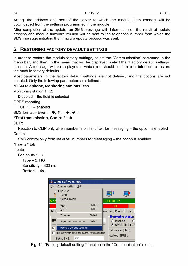
In order to restore the module factory settings, select the “Communication” command in the menu bar, and then, in the menu that will be displayed, select the “Factory default settings” function. A message will be displayed in which you should confirm your intention to restore the module factory defaults.
Most parameters in the factory default settings are not defined, and the options are not enabled. Only the following parameters are defined:
“GSM telephone, Monitoring stations” tab Monitoring station 1 / 2:
Disabled – the field is selected
GPRS reporting
TCP / IP – enabled
SMS format – Event = , , , , =
“Test transmission, Control” tab CLIP:
Reaction to CLIP only when number is on list of tel. for messaging – the option is enabled
Control:
SMS control only from list of tel. numbers for messaging – the option is enabled
“Inputs” tab Inputs:
For inputs 1 – 5
Type – 2: NO
Sensitivity – 300 ms
Restore – 4s.
Fig. 14. “Factory default settings” function in the “Communication” menu.
SATEL GPRS-T2 25
7. SPECIFICATIONS
Supply voltage ................................................................................................... 12 V DC ±15%
Standby current consumption ..........................................................................................75 mA
Maximum current consumption......................................................................................400 mA
Power supply required output current, min. ..........................................................................2 A
Permissible voltage at AC input ...........................................................................up to 25 V AC
FT output rating .............................................................................................. 50 mA / 12 V DC
Relay output rating (resistive load) ...................................................................... 2 A / 30 V DC
Environmental class................................................................................................................. II
Working temperature range .................................................................................... -10...+55 °C
Electronics board dimensions ................................................................................. 80 x 57 mm
Weight............................................................................................................................... 190 g