GPON OLT CLI USER MANUAL · 2020-01-23 · DG-GO4308-14E2SFPP GPON OLT CLI USER MANUAL . V1.1 ....
114
DG-GO4308-14E2SFPP GPON OLT CLI USER MANUAL V1.1 22-4-2019 As our products undergo continuous development the specifications are subject to change without prior notice.
Transcript of GPON OLT CLI USER MANUAL · 2020-01-23 · DG-GO4308-14E2SFPP GPON OLT CLI USER MANUAL . V1.1 ....

DG-GO4308-14E2SFPP
GPON OLT
CLI USER MANUAL
V1.1 22-4-2019
As our products undergo continuous development the specifications are subject to change without prior notice.

DG-GO4300 Series OLT CLI User Manual
2
Content 1 DG-GO4308 GPON OLT CLI User Manual
1. Access to OLT.................................................................................................... 1
2. Command Line Interface .................................................................................... 3
2.1 Abstract .................................................................................................................. 3
2.2 CLI configuration mode ........................................................................................... 3
2.3 CLI specialities ........................................................................................................ 4
2.3.1 Online help...................................................................................................... 4
2.3.2 Display specialities .......................................................................................... 6
2.3.3 History commands........................................................................................... 6
2.3.4 Error messages ................................................................................................ 6
2.3.5 Edit specialities ............................................................................................... 7
3. Port Configuration .............................................................................................. 8
3.1 Port configuration................................................................................................... 8
3.1.1 Enter port configure mode ............................................................................... 8
3.1.2 Enable /Disable port ........................................................................................ 8
3.1.3 Configure port description ............................................................................... 8
3.1.4 Configure port duplex mode ............................................................................ 9
3.1.5 Configure port speed ....................................................................................... 9
3.1.6 Configure port rate limitation ........................................................................ 10
3.1.7 Configure port VLAN mode .......................................................................... 10
3.1.8 Configure hybrid port VLAN ........................................................................ 11
3.1.9 Configure trunk port VLAN .......................................................................... 11
3.1.10 Configure port PVID ..................................................................................... 12
3.1.11 Configure access port VLAN ......................................................................... 12
3.1.12 Configure port flow control ........................................................................... 13
3.1.13 Configure port broadcast suppression ............................................................ 13
3.1.14 Configure port multicast suppression ............................................................. 14
3.1.15 Configure port unknown unicast suppression ................................................. 14

DG-GO4300 Series OLT CLI User Manual
3
3.1.16 Configure port isolation ................................................................................. 15
3.1.17 Configure port loopback ................................................................................ 15
3.1.18 Configure port loopback detection ................................................................. 15
3.1.19 Configure port jumboframe ........................................................................... 16
3.1.20 Show port statistics........................................................................................ 16
3.1.21 Clean port statistics ....................................................................................... 17
3.1.22 Show interface configurations ....................................................................... 17
3.2 Example ................................................................................................................ 18
4. Port Aggregation Configuration ........................................................................ 20
4.1 Introduction ......................................................................................................... 20
4.2 Port Aggregation Configuration ........................................................................ 20
4.2.1 Create static aggregation group ...................................................................... 20
4.2.2 Configure load balancing policy of aggregation group ................................... 20
4.2.3 Configure member port of aggregation group ................................................ 21
5. VLAN Configuration.......................................................................................... 22
5.1 VLAN configuration ............................................................................................ 22
5.1.1 Create/Delete VLAN ..................................................................................... 22
5.1.2 Configure/delete VLAN description .............................................................. 22
5.1.3 Configure/delete IP address and mask of VLAN ............................................ 23
5.2 Show VLAN information .................................................................................... 23
6. VLAN Translation/QinQ .................................................................................... 25
6.1 Configure VLAN translation/QinQ ......................................................................... 25
6.2 Example ................................................................................................................ 25
7. MAC Address Configuration ............................................................................. 26
7.1 Overview .............................................................................................................. 26
7.2 Configure MAC address ........................................................................................ 26
7.2.1 Configure MAC address table........................................................................ 26
7.2.2 Configure MAC address aging time ............................................................... 27
7.2.3 Clean MAC address table .............................................................................. 27
7.2.4 Configure maximum learnt MAC enties of port ............................................. 27
7.3 Show MAC address table ...................................................................................... 28
DG-GO4300 Series OLT CLI User Manual
4
7.3.1 Show MAC address table .............................................................................. 28
7.3.2 Show MAC address aging time...................................................................... 28
8. Configure Port Mirroring ................................................................................... 29
8.1 Configure mirroring destination port .................................................................... 29
8.2 Configure mirroring source port ........................................................................... 29
8.3 Delete port mirroring ............................................................................................ 30
9. IGMP Configuration .......................................................................................... 31
9.1 IGMP Snooping .................................................................................................. 31
9.1.1 Enable/disable IGMP Snooping ..................................................................... 31
9.1.2 Configure multicast data forwarding mode .................................................... 31
9.1.3 Configure port multicast VLAN .................................................................... 31
9.1.4 Configure multicast router port ...................................................................... 32
9.1.5 Configure static multicast .............................................................................. 32
9.1.6 Configure fast leave ...................................................................................... 33
9.1.7 Configure multicast group limit ..................................................................... 33
9.1.8 Configure parameters of special query ........................................................... 33
9.1.9 Configure parameters of general query .......................................................... 34
9.1.10 Configure source IP of query ......................................................................... 34
9.1.11 Configure multicast member aging time ........................................................ 34
9.1.12 Show multicast gourp information ................................................................. 35
9.1.13 Configure multcast on pon ............................................................................. 35
9.2 Example .............................................................................................................. 35
10. ACL Configuration ............................................................................................ 38
10.1 Overview .............................................................................................................. 38
10.2 ACL confiuration ................................................................................................... 38
10.2.1 IP standard ACL............................................................................................ 38
10.2.2 IP extended ACL ........................................................................................... 39
10.2.3 ACL based on MAC address ......................................................................... 39
10.2.4 ACL based on port binding ............................................................................ 40
10.2.5 ACL based on QoS ........................................................................................ 41
10.2.6 ACL rule apply to port .................................................................................. 42

DG-GO4300 Series OLT CLI User Manual
5
10.3 Example ................................................................................................................ 42
11. QoS Configuration ............................................................................................ 44
11.1 Configure queue scheduling mode ........................................................................ 44
11.2 Configure queue mapping..................................................................................... 44
12. STP Configuration ............................................................................................ 46
12.1 STP default settings ....................................................................................... 46
12.2 Cofigure STP .................................................................................................. 46
12.2.1 Enable device’s STP function ........................................................................ 46
12.2.2 Enable port STP ............................................................................................ 47
12.2.3 Configure spanning tree mode ....................................................................... 47
12.2.4 Configure bridge priority ............................................................................... 47
12.2.5 Configure forward delay ................................................................................ 48
12.2.6 Configure hello time ...................................................................................... 48
12.2.7 Configure max age time ................................................................................ 49
12.2.8 Configure priority of designated port ............................................................. 49
12.2.9 Configure path cost of designated port ........................................................... 50
12.2.10 Configure edge port ....................................................................................... 50
12.2.11 Configure point to point mode ....................................................................... 51
12.3 Show STP information ................................................................................... 52
13. Static Route Configuration................................................................................ 53
14. IP Management Configuration .......................................................................... 54
14.1 Configure outband management .................................................................. 54
14.1.1 Enter AUX port configuration mode .............................................................. 54
14.1.2 Configure outband management IP address and mask .................................... 54
14.1.3 Show AUX port information ......................................................................... 54
14.2 Configure inband management ..................................................................... 55
14.3 Confgure manangement gateway ................................................................. 55
14.4 Confgure DNS ................................................................................................ 57
15. ARP Proxy ....................................................................................................... 57
16. DHCP Management Configuration ................................................................... 58
16.1 Configure DHCP server ............................................................................................. 58

DG-GO4300 Series OLT CLI User Manual
6
16.2 Configure DHCP relay ............................................................................................... 58
16.3 Configure DHCP Snooping ...................................................................................... 60
17. PON Management Configuration...................................................................... 63
17.1 Show PON port info and optical power ................................................................. 63
17.1.1 Show Pon port statistics ................................................................................. 63
17.1.2 Show PON port optical power ....................................................................... 63
17.1.3 Show ONU optical transceiver ...................................................................... 63
17.2 PON port configuration ......................................................................................... 64
17.2.1 Enable/Disable PON...................................................................................... 64
17.3 ONU auto-learn configuration............................................................................... 64
18. ONU Management Configuration ..................................................................... 65
18.1 ONU basic configuration ....................................................................................... 65
18.1.1 Show auto-find ONU..................................................................................... 65
18.1.2 ONU automatic authorize .............................................................................. 65
18.1.3 Show ONU authorized info ........................................................................... 65
18.1.4 Show ONU authorized detail-info .................................................................. 66
18.1.5 Activate|deactivate ONU ............................................................................... 66
18.1.6 ONU authorization ........................................................................................ 66
18.1.7 Configure ONU description string ................................................................. 66
18.2 ONU remote configuration ................................................................................... 67
18.2.1 Show ONU SFP info ..................................................................................... 67
18.2.2 Upgrade ONU ............................................................................................... 67
18.2.3 Auto-upgrade ONU ....................................................................................... 68
18.2.4 Reboot ONU ................................................................................................. 68
18.2.5 TCONT Configuration .................................................................................. 68
18.2.6 GEMPORT Configuration ............................................................................. 69
18.2.7 ONU Service Configuration .......................................................................... 69
18.2.8 Configure the service-port ............................................................................. 70
18.2.9 ONU UNI Configuration ............................................................................... 71
18.2.10 ONU FEC Configuration ............................................................................... 71
18.2.11 Show ONU Service ....................................................................................... 72

DG-GO4300 Series OLT CLI User Manual
7
18.2.12 Show ONU capability.................................................................................... 72
18.3 ONU remote port configuration ............................................................................ 72
18.3.1 ONU port enable|disable................................................................................ 72
18.3.2 ONU port autonegotiation ............................................................................. 72
18.3.3 ONU port flow control configuration ............................................................. 73
18.3.4 Multicast vlan configuration .......................................................................... 73
18.3.5 Configure onu iphost ..................................................................................... 73
18.3.6 ONU port multicast tag-strip configuration .................................................... 74
18.3.7 Example for SFU........................................................................................... 74
18.3.8 Example for HGU ......................................................................................... 75
18.4 Rogue-onu configuration ...................................................................................... 76
18.4.1 Configure the rogue-onu-detect ..................................................................... 76
18.4.2 Configure the rogue-onu status ...................................................................... 77
19. ONU template management ............................................................................. 78
19.1 Summary of the ONU template ............................................................................. 78
19.2 ONU profile configuration ..................................................................................... 78
19.3 DBA bandwidth template configuation ................................................................. 79
19.4 Traffic template configuation ................................................................................ 80
19.5 Line template configuation ................................................................................... 80
19.6 SRV template configuation ................................................................................... 82
19.7 Alarm threshold template configuration ............................................................... 83
19.8 Show/Delete the profile configuration .................................................................. 83
20. ONU auto-learn configuration ........................................................................... 85
20.1 ONU auto-learn .................................................................................................... 85
20.2 Enable auto-learn ................................................................................................. 85
21. System Management ....................................................................................... 86
21.1 Configuration file management ............................................................................ 86
21.1.1 Save configurations ....................................................................................... 86
21.1.2 Erase configurations ...................................................................................... 86
21.1.3 Show startup configurations .......................................................................... 86
21.1.4 Show running configurations ......................................................................... 86
DG-GO4300 Series OLT CLI User Manual
8
21.1.5 Upload/download configuration file............................................................... 87
21.2 Check the system information .............................................................................. 87
21.2.1 Check system running information ................................................................ 87
21.2.2 Check version information............................................................................. 87
21.2.3 Check system running time............................................................................ 87
21.3 System basic configurations .................................................................................. 88
21.3.1 Configure system name ................................................................................. 88
21.3.2 Configure terminal display attribute ............................................................... 88
21.3.3 Configure terminal time-out value ................................................................. 88
21.4 System basic operations ....................................................................................... 89
21.4.1 Upgrade system ............................................................................................. 89
21.4.2 Network connectivity test .............................................................................. 89
21.4.3 Reboot system ............................................................................................... 89
21.4.4 Telnet ............................................................................................................ 89
21.4.5 Configure RTC system time .......................................................................... 89
21.4.6 NTP Client .................................................................................................... 90
21.4.7 TimeZone configuration ................................................................................ 90
21.4.8 Fan control .................................................................................................... 90
21.5 Debug information ............................................................................................... 91
21.5.1 Enable/disable CPU debug information ......................................................... 91
21.5.2 Enable/disable each function module debug information ................................ 91
22 User Management ............................................................................................ 92
22.1 User privilege .................................................................................................. 92
22.2 Default user..................................................................................................... 92
22.3 Add user account ........................................................................................... 92
22.4 Show user account list ................................................................................... 92
22.5 Delete user account ....................................................................................... 92
22.6 Modify password ............................................................................................ 93
23 SNMP Configuration......................................................................................... 94
23.1 SNMP introduction ......................................................................................... 94
23.2 SNMP version and MIB ................................................................................. 94

DG-GO4300 Series OLT CLI User Manual
9
23.3 Configure SNMP ............................................................................................ 95
23.3.1 Configure community .................................................................................... 95
23.3.2 Configure Trap the target host address ........................................................... 95
23.3.3 Configure Administrator ID and contact method ............................................ 96
23.3.4 Configure Ethernet switch location information ............................................. 96
24 Alarm and Event Management ......................................................................... 97
24.1 Alarm and event introduction ............................................................................... 97
24.2 Alarm management .............................................................................................. 97
24.2.1 System alarms ............................................................................................... 97
24.2.2 PON alarms ................................................................................................... 98
24.3 Event management............................................................................................. 101
24.3.1 System events.............................................................................................. 101
24.3.2 PON events ................................................................................................. 101
24.3.3 ONU events ................................................................................................ 102
25 System Log .....................................................................................................103
25.1 System log introduction ............................................................................... 103
25.1.1 Log type ...................................................................................................... 103
25.1.2 System log level .......................................................................................... 103
25.2 Configure system log ................................................................................... 104
25.2.1 Show system log ......................................................................................... 104
25.2.2 Clear system log .......................................................................................... 104
25.2.3 Configure system log server ........................................................................ 104
25.2.4 Configure save level of system log .............................................................. 104
25.2.5 Save system log to flash .............................................................................. 105
25.2.6 Clear system log in flash ............................................................................. 105
25.2.7 Upload system log ....................................................................................... 105

1
1. Access to OLT
You can access to OLT by CLI via console cable or telnet. This charpter introduces how to access to OLT CLI via console cable. 1. Connect PC to OLT console port by console cable. 2. Run hypeterminal or other simulation tools such as secureCRT and Putty in PC. Set
parameters as follows. Baudrate: 115200
Data bits: 8 Parity: none Stop bits: 1 Follow control: none
COM port properties
After truned on the power, there is boot information printing. After startup, press enter and

DG-GO4300 Series OLT CLI User Manual
2
input username and password to login. Notice: The default username and password of CLI both are admin. For example, Login: admin Password: admin gpon-olt> enable Password: admin gpon-olt#
Input commands to configure or check device’s status. Input “?” any time you need help. This document will introduce each command Begin at next charpter.
DG-GO4300 Series OLT CLI User Manual
3
2. Command Line Interface
2.1 Abstract
gpon-olt provides command line interface for configuration and management. The following is its specialities. Configure from console port. Input “?” any time you need help. Provide network test command, such as ping, for diagnosing connection. Provide FTP service for uploading and downloading files. Provide Doskey analogous function, you can execute a history command. Support ambiguous keywords searching, you just need to input unconflict keywords and
press “tab” or “?”.
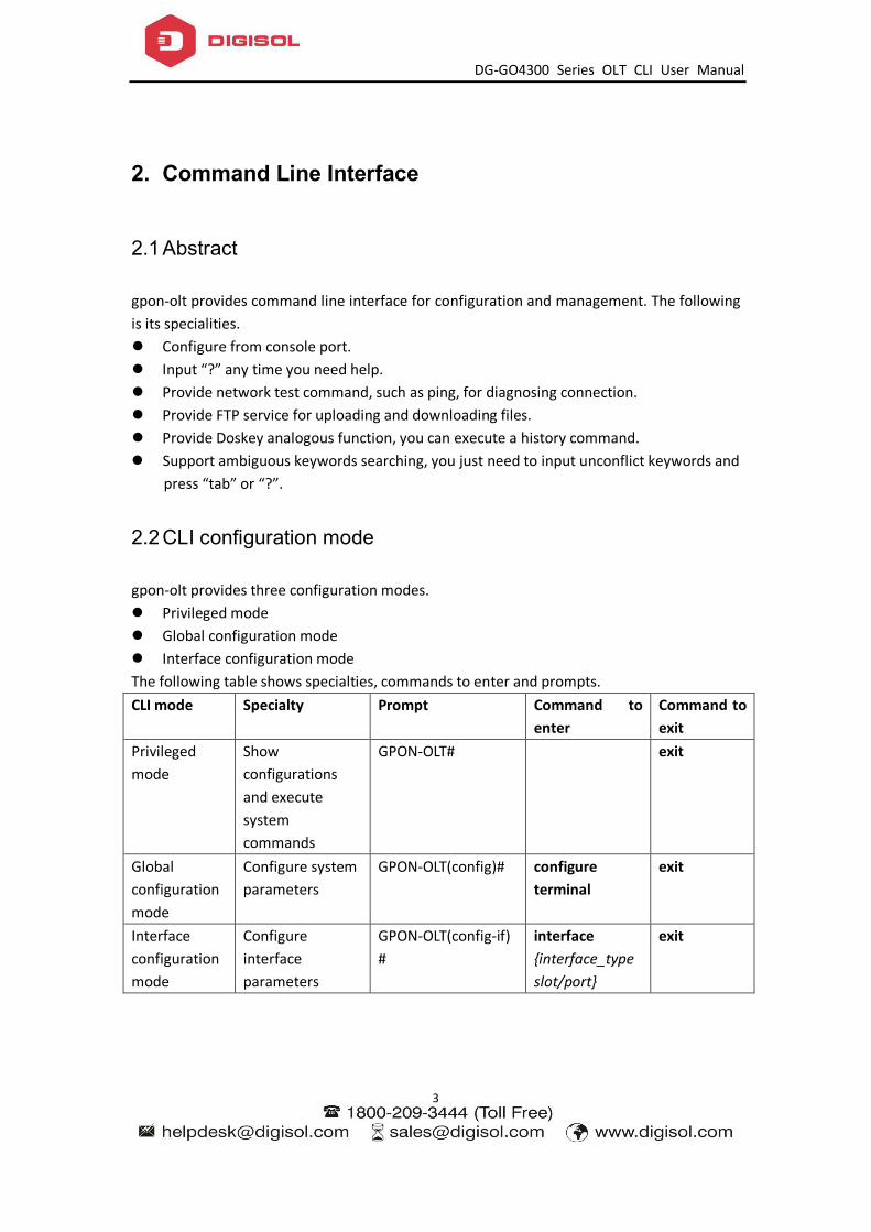
2.2 CLI configuration mode
gpon-olt provides three configuration modes. Privileged mode Global configuration mode Interface configuration mode The following table shows specialties, commands to enter and prompts. CLI mode Specialty Prompt Command to
enter Command to exit
Privileged mode
Show configurations and execute system commands
GPON-OLT# exit
Global configuration mode
Configure system parameters
GPON-OLT(config)# configure terminal
exit
Interface configuration mode
Configure interface parameters
GPON-OLT(config-if)#
interface {interface_type slot/port}
exit
DG-GO4300 Series OLT CLI User Manual
4
2.3 CLI specialities
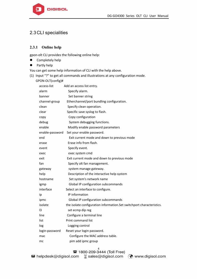
2.3.1 Online help
gpon-olt CLI provides the following online help: Completely help Partly helpYou can get some help information of CLI with the help above.(1) Input “?” to get all commands and illustrations at any configuration mode.
GPON-OLT(config)# access-list Add an access list entry. alarm Specify alarm. banner Set banner string channel-group Etherchannel/port bundling configuration. clean Specify clean operation. clear Specific save syslog to flash. copy Copy configuration debug System debugging functions. enable Modify enable password parameters enable-password Set your enable password. end Exit current mode and down to previous mode erase Erase info from flash. event Specify event. exec exec system cmd exit Exit current mode and down to previous mode fan Specify olt fan management. gateway system manage gateway. help Description of the interactive help system hostname Set system's network name igmp Global IP configuration subcommands interface Select an interface to configure. ip IP information ipmc Global IP configuration subcommands isolate the isolate configuration information.Set switchport characteristics. l3 set ecmp dip reg line Configure a terminal line list Print command list log Logging control login-password Reset your login password. mac Configure the MAC address table. mc pim add ipmc group

DG-GO4300 Series OLT CLI User Manual
5
monitor Configure SPAN monitoring. no Negate a command or set its default. password Assign the terminal connection password pim pim add ipmc group ping ping command profile Select profile to configure. queue-scheduler Configure egress queueing policy. quit Exit current mode and down to previous mode reboot Reboot the switch. save Specific save syslog to flash. service Set up miscellaneous service set Specify set command. show Show information snmp-server Snmp server config spanning-tree Config STPD information. storm-control Specify the storm control. switch switch to shell syslog Specific system log save level,which syslog level not less than level will save to flash. tftp Specify tftp download. time Specify system time configuration. upgrade Specify upgrade system. upload Upload file for software or user config. user Manage System's users. vlan Vlan commands. write Write running configuration to memory, network, or terminal
(2) Input “?” behind a command, it will display all key words and illustrations when this site should be a key word. GPON-OLT(config)# interface aux aux interface. gpon Specify gpon interface gigabitethernet GigabitEthernet IEEE 802.3z. vlan Config vlan information.
(3) Input “?” behind a command, it will display description of parameters when this site should be a parameter. GPON-OLT(config)# access-list <0-999> IP standard access list. <1000-1999> IP extended access list. <2000-2999> L2 packet header access list. <3000-3999> User define field access list. <4000-4999> Vlan translation access list. <5000-5999> Port business access list.
DG-GO4300 Series OLT CLI User Manual
6
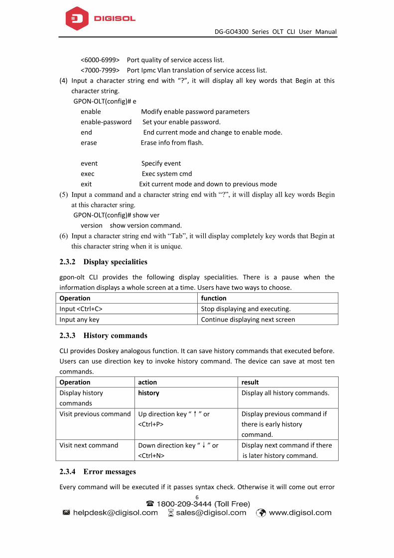
<6000-6999> Port quality of service access list. <7000-7999> Port Ipmc Vlan translation of service access list.
(4) Input a character string end with “?”, it will display all key words that Begin at this character string. GPON-OLT(config)# e enable Modify enable password parameters enable-password Set your enable password. end End current mode and change to enable mode. erase Erase info from flash. event Specify event exec Exec system cmd exit Exit current mode and down to previous mode
(5) Input a command and a character string end with “?”, it will display all key words Begin at this character sring. GPON-OLT(config)# show ver version show version command.
(6) Input a character string end with “Tab”, it will display completely key words that Begin at this character string when it is unique.
2.3.2 Display specialities
gpon-olt CLI provides the following display specialities. There is a pause when the information displays a whole screen at a time. Users have two ways to choose. Operation function Input <Ctrl+C> Stop displaying and executing. Input any key Continue displaying next screen
2.3.3 History commands
CLI provides Doskey analogous function. It can save history commands that executed before. Users can use direction key to invoke history command. The device can save at most ten commands. Operation action result Display history commands
history Display all history commands.
Visit previous command Up direction key “↑” or <Ctrl+P>
Display previous command if there is early history command.
Visit next command Down direction key “↓” or <Ctrl+N>
Display next command if there is later history command.
2.3.4 Error messages
Every command will be executed if it passes syntax check. Otherwise it will come out error

DG-GO4300 Series OLT CLI User Manual
7
message. The following table shows some frequent errors. Error messages Reasons Unknown command No this command
No this key word Parameter type error Parameter out of range
Command incomplete Command is not complete Too many parameters Too many parameters Ambiguous command Command is ambiguous
2.3.5 Edit specialities
CLI provides basic edit function. Every command supports maxum 256 characters. The following table shows how to edit. operation function Generally input Insert character at cursor position and move
cursor to right if edit buffer has enough space.
Backspace key Delete the character in front of cursor. Left direction key ← or <Ctrl+B> Cursor moves one character position
towards the left. Right direction key → or <Ctrl+F> Cursor moves one character position
towards the right. Up direction key↑or <Ctrl+P> Down direction key↓or <Ctrl+N>
Display history command.
Tab key Input incomplete key words end with Tab key, CLI will provide partly help. If it is unique, the key word which matches what you input will be used and display in another row. If it should be parameter, or the key word is mismatched or matched but not unique, CLI will use what you input and display in another row.

DG-GO4300 Series OLT CLI User Manual
8
3. Port Configuration
3.1 Port configuration
3.1.1 Enter port configure mode
Begin at privileged configuration mode, input the following commands to enter port configuration mode.
Command Function
Step 1 configure terminal Enter global configuration mode. Step 2 interface {interface_type slot/port} Enter interface configuration
mode.
3.1.2 Enable /Disable port
You can use these commands to enable or disable port. The ports are enabled by default. If you want a port not to transfer data, you can shutdown it. Begin at privileged configuration mode, enable or disable ports as the following table shows.
Command Function
Step 1 configure terminal Enter global configuration mode. Step 2 interface {interface_type slot/port} Enter interface configuration
mode.
Step 3a no shutdown Enable port
Step 3b shutdown Disable port.
Step 4 exit Exit to gloable configuration mode.
Step 5 show interface {interface_type slot/port}
Show interface configurations.
Step 6 write Save configurations.
3.1.3 Configure port description
This command is used to configure port description. There is no description by default. Begin at privileged configuration mode, configure port description as the following table shows.
Command Function
Step 1 configure terminal Enter global configuration mode.

DG-GO4300 Series OLT CLI User Manual
9
Step 2 interface {interface_type slot/port} Enter interface configuration mode.
Step 3a description <string> Configure port description.
Step 3b no description Delete description.
Step 4 exit Exit to global configuration mode.
Step 5 show interface {interface_type slot/port}
Show interface configurations.
Step 6 write Save configurations.
3.1.4 Configure port duplex mode
Duplex includes full duplex and half duplex. When it works at full duplex, port can transmit and receive data at the same time; when it works at half duplex, port can only transmit or receive data at the same time. The duplex is auto by default. Begin at privileged configuration mode, configure port duplex mode as the following table shows.
Command Function
Step 1 configure terminal Enter global configuration mode. Step 2 interface {interface_type slot/port} Enter interface configuration
mode.
Step 3a duplex { auto | full | half } Configure port duplex mode.
Step 3b no duplex Reset duplex mode to default.
Step 4 exit Exit to global configuration mode.
Step 5 show interface {interface_type slot/port}
Show interface configurations.
Step6 write Save configurations.
3.1.5 Configure port speed
When port speed mode is auto, the actual speed of port is determined by the automated negotiation result with opposite port. The speed is auto by default. Begin at privileged configuration mode, configure port speed as the following table shows.
Command Function
Step 1 configure terminal Enter global configuration mode. Step 2 interface {interface_type slot/port} Enter interface configuration
mode.
Step 3a speed { 10 | 100 | 1000 | auto } Configure port speed.

DG-GO4300 Series OLT CLI User Manual
10
Step 3b no speed Reset port speed to default.
Step 4 exit Exit to global configuration mode.
Step 5 show interface {interface_type slot/port}
Show interface configurations.
Step 6 write Save configurations.
3.1.6 Configure port rate limitation
Begin at privileged configuration mode, configure port rate limitation as the following table shows.
Command Function
Step 1 configure terminal Enter global configuration mode. Step 2 interface {interface_type slot/port} Enter interface configuration
mode. Step 3a line-rate {ingress | egress} bps
value
Configure port rate limitation. Value range: 64-1000000, it should be integral multiple of 64kbps.
Step 3b no line-rate {ingress | egress} Delete port rate limitation configurations.
Step 4 exit Exit to global configuration mode.
Step 5 show interface {interface_type slot/port}
Show interface configurations.
Step6 write Save configurations.
3.1.7 Configure port VLAN mode
Each port has three VLAN mode, access, trunk and hybrid. Access mode is usually used for port that connects with PC or other terminals, only one
VLAN can be set up. Trunk mode is usually used for port that connects with switch; one or more VLAN can be set up. Hybrid mode can be used for port that connects with PC or switch. Default VLAN mode is hybrid.
Begin at privileged configuration mode, configure port VLAN mode as the following table shows.
Command Function
Step 1 configure terminal Enter global configuration mode. Step 2 interface {interface_type slot/port} Enter interface configuration
mode.
Step 3a switchport mode { access | trunk | Configure port VLAN mode.

DG-GO4300 Series OLT CLI User Manual
11
hybrid}
Step 3b no switchport mode Reset VLAN mode to default.
Step 4 exit Exit to global configuration mode.
Step 5 show interface {interface_type slot/port}
Show interface configurations.
Step 6 write Save configurations.
Notice: All VLAN configurations will lose when you change port VLAN mode.
3.1.8 Configure hybrid port VLAN
Hybrid port can belong to several VLAN. It can be used to connect with switch or router, and also terminal host. Begin at privileged configuration mode, configure hybrid port VLAN as the following table shows.
Command Function
Step 1 configure terminal Enter global configuration mode. Step 2 interface {interface_type slot/port} Enter interface configuration mode. Step 3a switchport hybrid vlan vlan_id
{tagged | untagged} Add specific VLAN to hybrid port.
Step 3b no switchport hybrid vlan vlan_id Remove VLAN from port.
Step 4 exit Exit to global configuration mode.
Step 5 show interface {interface_type
slot/port}
Show interface configurations.
Step 6 write Save configurations.
Notice: You must configure PVID for the port that if it is configured untagged mode. PVID is the same as VLAN ID. Please refer to 3.1.10.
3.1.9 Configure trunk port VLAN
Trunk mode port can belong to several VLAN. It is usually used to connect with switches routers. Begin at privileged configuration mode, configure trunk port VLAN as the following table shows.
Command Function
Step 1 configure terminal Enter global configuration Step 2 interface {interface_type slot/port} Enter interface configuration
DG-GO4300 Series OLT CLI User Manual
12
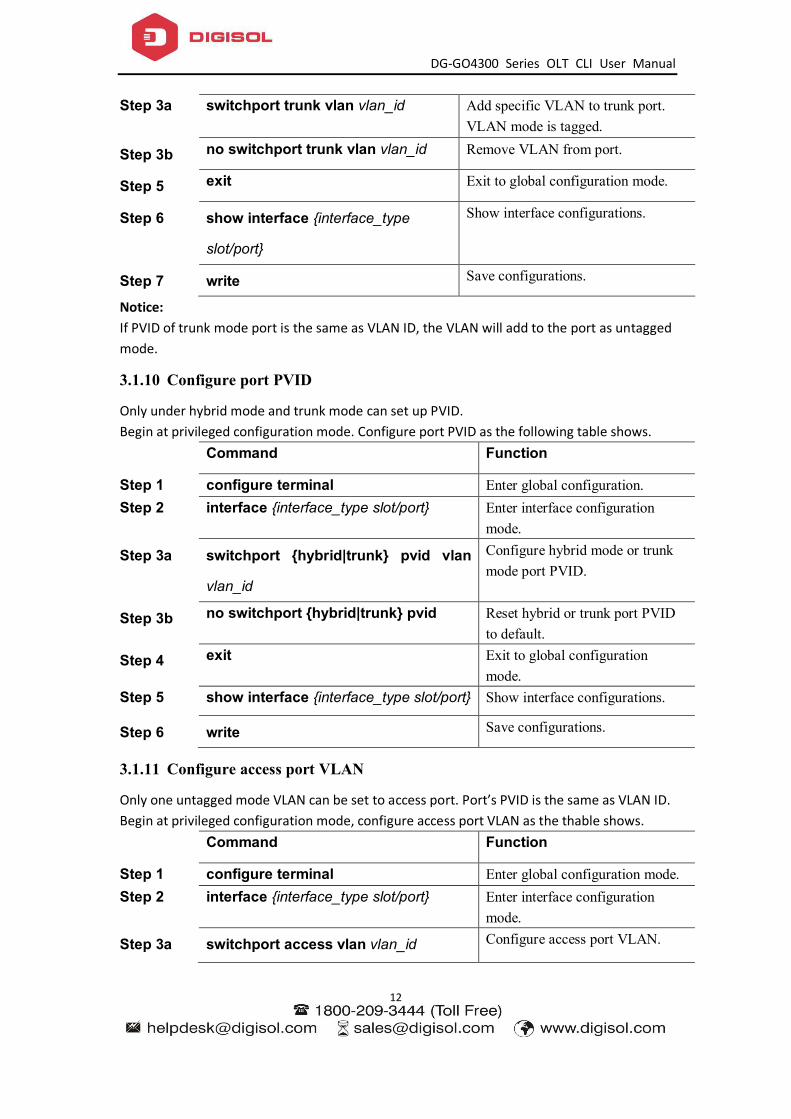
Step 3a switchport trunk vlan vlan_id Add specific VLAN to trunk port. VLAN mode is tagged.
Step 3b no switchport trunk vlan vlan_id Remove VLAN from port.
Step 5 exit Exit to global configuration mode.
Step 6 show interface {interface_type
slot/port}
Show interface configurations.
Step 7 write Save configurations.
Notice: If PVID of trunk mode port is the same as VLAN ID, the VLAN will add to the port as untagged mode.
3.1.10 Configure port PVID
Only under hybrid mode and trunk mode can set up PVID. Begin at privileged configuration mode. Configure port PVID as the following table shows.
Command Function
Step 1 configure terminal Enter global configuration. Step 2 interface {interface_type slot/port} Enter interface configuration
mode.
Step 3a switchport {hybrid|trunk} pvid vlan
vlan_id
Configure hybrid mode or trunk mode port PVID.
Step 3b no switchport {hybrid|trunk} pvid Reset hybrid or trunk port PVID to default.
Step 4 exit Exit to global configuration mode.
Step 5 show interface {interface_type slot/port} Show interface configurations.
Step 6 write Save configurations.
3.1.11 Configure access port VLAN
Only one untagged mode VLAN can be set to access port. Port’s PVID is the same as VLAN ID. Begin at privileged configuration mode, configure access port VLAN as the thable shows.
Command Function
Step 1 configure terminal Enter global configuration mode. Step 2 interface {interface_type slot/port} Enter interface configuration
mode.
Step 3a switchport access vlan vlan_id Configure access port VLAN.

DG-GO4300 Series OLT CLI User Manual
13
Step 3b no switchport access vlan Reset access port VLAN to default.
Step 4 exit Exit to global configuration mode.
Step 5 show interface {interface_type slot/port} Show interface configurations.
Step 6 write Save configurations.
3.1.12 Configure port flow control
Begin at privileged configuration mode, configure port flow control as the following table shows.
Command Function
Step 1 configure terminal Enter global configuration mode. Step 2 interface {interface_type slot/port} Enter interface configuration mode. Step 3a flowcontrol on Enable flow control function.
Step 3b no flowcontrol Disable flow control function.
Step 4 exit Exit to global configuration mode.
Step 5 show interface {interface_type slot/port} Show interface configurations.
Step 6 write Save configurations.
3.1.13 Configure port broadcast suppression
Begin at privileged configuration mode, configure port broadcast suppression as the following table shows.
Command Function
Step 1 configure terminal Enter global configuration mode.
Step 2 interface {interface_type slot/port} Enter interface configuration mode.
Step 3a storm-control broadcast bps value Configure broadcast suppression. Value range: 64-1000000, it should be integral multiple of 64kbps.
Step 3b no storm-control broadcast Remove broadcast suppression.
Step 4 exit Exit global configuration mode.
Step 5 show interface {interface_type slot/port} Show interface configurations.

DG-GO4300 Series OLT CLI User Manual
14
Step 6 write Save configurations.
3.1.14 Configure port multicast suppression
Begin at privileged configuration mode, configure port multicast suppression as the following table shows.
Command Function
Step 1 configure terminal Enter global configuration mode.
Step 2 interface {interface_type slot/port} Enter interface configuration mode.
Step 3a storm-control multicast bps value Configure multicast suppression. Value range: 64-1000000, it should be integral multiple of 64kbps.
Step 3b no storm-control multicast Remove multicast suppression.
Step 4 exit Exit global configuration mode.
Step 5 show interface {interface_type slot/port} Show interface configurations.
Step 6 write Save configurations.
3.1.15 Configure port unknown unicast suppression
Begin at privileged configuration mode, configure port unknown unicast suppression as the following table shows.
Command Function
Step 1 configure terminal Enter global configuration mode. Step 2 interface {interface_type slot/port} Enter interface configuration
mode. Step 3a storm-control unicast bps value Configure unknown unicast
suppression. Value range: 64-1000000, it should be integral multiple of 64kbps.
Step 3b no storm-control unicast Remove unknown unicast suppression.
Step 4 exit Exit global configuration mode.
Step 5 show interface {interface_type slot/port} Show interface configurations.
Step 6 write Save configurations.

DG-GO4300 Series OLT CLI User Manual
15
3.1.16 Configure port isolation
With this function, customers can add ports to a same isolation group so that these ports can be isolated among L2 and L3 steams. This will improve security of network and provide flexible networking scheme. Begin at privileged configuration mode, configure port isolation as the following table shows.
Command Function
Step 1 configure terminal Enter global configuration mode. Step 2 interface {interface_type slot/port} Enter interface configuration
mode. Step 3a switchport isolate Add port to isolation group.
Step 3b no switchport isolate Remove port from isolation group.
Step 4 exit Exit to global configuration mode.
Step 5a show interface {interface_type slot/port} Show interface configurations.
Step 5b show isolate port Show isolation group.
Step 6 write Save configurations.
3.1.17 Configure port loopback
Begin at privileged configuration mode, configure port loopback as the following table shows.
Command Function
Step 1 configure terminal Enter global configuration mode. Step 2 interface {interface_type slot/port} Enter interface configuration
mode. Step 3 loopback [internal | external | outside] Internal means cpu inner
loopback. External means cpu outer loopback. Outside means external data loopback.
Step 4 exit Exit to global configuration mode.
Notice: When testing port loopback function, please disable port loopback detection. Please refer to 3.1.18.
3.1.18 Configure port loopback detection

DG-GO4300 Series OLT CLI User Manual
16
Begin at privileged configuration mode, configure port loopback detection as the following table shows.
Command Function
Step 1 configure terminal Enter global configuration mode.
Step 2a loopback detect enable Enable port loopback detection.
Step 2b no loopback detect Disable port loopback detection.
Step 3 show loopback detect Show port loopback detection status.
Step 4 exit Exit to global configuration mode.
3.1.19 Configure port jumboframe
Begin at privileged configuration mode, configure jumboframe that the port can pass as the following table shows.
Command Function
Step 1 configure terminal Enter global configuration mode. Step 2 interface {interface_type slot/port} Enter interface configuration
mode.
Step 3a jumboframe enable Enable jumboframe transmission. By default, switch chipset supports transmitting maximum 1536 bytes frame; PON chipset supports transmitting maximum 2047 bytes frame.
Step 3b no jumboframe Disable jumboframe transmission.
Step 4 exit Exit to global configuration mode.
3.1.20 Show port statistics
Begin at privileged configuration mode, show port statistics as the following table shows.
Command Function
Step 1 configure terminal Enter global configuration mode. Step 2 interface {interface_type slot/port} Enter interface configuration
mode. Step 3 show statistics Show port statistics.
Step 4 exit Exit to global configuration mode.

DG-GO4300 Series OLT CLI User Manual
17
3.1.21 Clean port statistics
Begin at privileged configuration mode, clean port statistics as the following table shows.
Command Function
Step 1 configure terminal Enter global configuration mode.
Step 2 show interface {interface_type slot/port} Show port statistics.
Step 3 clean statistics Clean port statistics.
3.1.22 Show interface configurations
Operation Command
Show interface configurations. Show interface {interface_type slot/port}
In the system, interface gigabitethernet 0/1~0/x stands for uplink port 1~x. Interface gpon0/1~0/x stands for GPON port 1~x. For example, display configurations of uplink port 5. GPON-OLT(config)# show interface gigabitethernet 0/5 Interface gigabitEthernet0/5's information. GigabitEthernet0/5 current state : Down Hardware Type is Gigabit Ethernet, Hardware address is 0:0:0:0:0:0 The Maximum Transmit Unit is 1500 Media type is twisted pair, loopback not set Port hardware type is 1000Base-TX Link speed type: autonegotiation, Link duplex type: autonegotiation Current link state: Down Current autonegotiation mode: enable Current link speed: 1000Mbps, Current link mode: half-duplex Flow Control: disable MDIX Mode: force The Maximum Frame Length is 1536 Broadcast storm control: 512 fps Multicast storm control: disable Unknow unicast storm control: 512 fps Ingress line rate control: no limit Egress line rate control: no limit mac address learn state : enable, no limit Port priority: 0 PVID: 1 Port combo mode: null Isolate member : yes Port link-type: hybrid Untagged VLAN ID: 1
DG-GO4300 Series OLT CLI User Manual
18
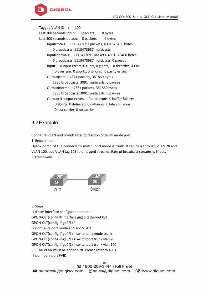
Tagged VLAN ID : 100 Last 300 seconds input: 0 packets 0 bytes Last 300 seconds output: 0 packets 0 bytes Input(total): 1113473691 packets, 4081075466 bytes 0 broadcasts, 1113473687 multicasts Input(normal): 1113473691 packets, 4081075466 bytes 0 broadcasts, 1113473687 multicasts, 0 pauses Input: 0 input errors, 0 runts, 0 giants, 0 throttles, 4 CRC 0 overruns, 0 aborts, 0 ignored, 0 parity errors Output(total): 4371 packets, 351860 bytes 1280 broadcasts, 3091 multicasts, 0 pauses Output(normal): 4371 packets, 351860 bytes 1280 broadcasts, 3091 multicasts, 0 pauses Output: 0 output errors, 0 underruns, 0 buffer failures 0 aborts, 0 deferred, 0 collisions, 0 late collisions 0 lost carrier, 0 no carrier
3.2 Example
Configure VLAN and broadcast suppresstion of trunk mode port. 1. Requirement Uplink port 1 of OLT connects to switch, port mode is trunk. It can pass through VLAN 20 and VLAN 100, add VLAN tag 123 to untagged streams. Rate of broadcast streams is 64bps. 2. Framework
3. Steps (1)Enter interface configuration mode. GPON-OLT(config)# interface gigabitethernet 0/1 GPON-OLT(config-if-ge0/1) # (2)configure port mode and add VLAN GPON-OLT(config-if-ge0/1) # switchport mode trunk GPON-OLT(config-if-ge0/1) # switchport trunk vlan 20 GPON-OLT(config-if-ge0/1) # switchport trunk vlan 100 PS. The VLAN must be added first. Please refer to 4.1.1. (3)configure port PVID

DG-GO4300 Series OLT CLI User Manual
19
GPON-OLT(config-if-ge0/1) # switchport trunk pvid vlan 123 (4)configure port broadcast suppression GPON-OLT(config-if-ge0/1) # storm-control broadcast pps 64

DG-GO4300 Series OLT CLI User Manual
20
4. Port Aggregation Configuration
4.1 Introduction
Port aggregation is that several ports constitute an aggregation group so that it can share responsibility for traffic load in each port. When one link is broken down, the traffic will switch to another automatically to ensure traffic is unblocked. It seems that the aggregation group is the same as a port.
In an aggregation group, member ports must have the same speed, the same duplex mode and the same basic configurations. Basic configurations contain: (1) STP configurations such as STP status, link properties (e.g. p2p port), priority, cost, message format, loopdetect status, edge port or not. (2) QoS configurations such as rate limiting, priority mark, 802.1p priority, congestion avoidance. (3) VLAN configurations such as VLAN ID, PVID. (4) Port link type such as trunk mode, hybrid mode and access mode. (5) GVRP configurations such as switch status, registration type, timer value.
4.2 Port Aggregation Configuration
4.2.1 Create static aggregation group
At most 4 groups can be created. You can add 4 member ports altogether in every group and at most 4 ports will come into being aggregation at the same time. Every group is defined as a channel group; the commands are centre on channel group.
Command Function
Step 1 configure terminal Enter global configuration mode.
Step 2a channel-group <1-4> mode static Create static aggregation group.
Step 2b no channel-group <1-4> Delete static aggregation group.
Step 3 show channel-group summary Show static aggregation group configuration.
4.2.2 Configure load balancing policy of aggregation group
Configuring load balancing policy includes source MAC, destination MAC, both source and destination MAC, source IP, destination IP, both source and destination IP. Default load

DG-GO4300 Series OLT CLI User Manual
21
balancing policy is based on source MAC.
Command Function
Step 1 configure terminal Enter global configuration mode.
Step 2 channel-group <1-4> load-balance {smac|dmac|sdmac|sip|dip|sdip}
Specify which link is used to transmit traffic in aggregation group.
Step 3 show channel-group summary Show aggregation configurations.
4.2.3 Configure member port of aggregation group
Command Function
Step 1 configure terminal Enter global configuration mode.
Step 2 interface {interface_type slot/port} Enter interface configuration mode.
Step 3a channel-group <1-4> Add current port to specific channel group.
Step 3b no channel-group <1-4> Delete current port from specific channel group.
Step 4 exit Exit global configuration mode.
Step 5 show channel-group summary Show aggregation gourp configurations.

DG-GO4300 Series OLT CLI User Manual
22
5. VLAN Configuration
5.1 VLAN configuration
VLAN configuration mainly contains: Create/delete VLAN Configure/delete VLAN description Configure/delete IP address and mask of VLAN
5.1.1 Create/Delete VLAN
Begin at privileged configuration mode, create or delete VLAN as the following table shows. Command Function Step 1 configure terminal Enter global configuration
mode. Step 2a vlan vlan_id Create VLAN or enter VLAN
interface configuration mode. VLAN ID range is from 1 to 4094.
Step 2b no vlan vlan_id Delete specific VLAN. Step 3 exit Exit to global configuration
mode. Step 4a show vlan [vlan_id/all] Show VLAN configurations.
Choosing all means display all existed VLAN. And choosing vlan_id means display information of specific VLAN.
Step 4b show vlan Show information of all existed VLAN.
Step 5 write Save configurations.
5.1.2 Configure/delete VLAN description
Begin at privileged configuration mode, configure or delete VLAN description as the following table shows. Command Function Step 1 configure terminal Enter global configuration
mode. Step 2 interface vlan vlan_id Create VLAN or enter VLAN
infterface configuration mode. VLAN ID range is from 1 to

DG-GO4300 Series OLT CLI User Manual
23
4094. Step 3a description string Configure VLAN description.
Step 3b no description Delete VLAN description.
Step 4 exit Exit to bloble configuration mode.
Step 5 show interface vlan vlan_id Show VLAN interface information.
Step 6 write Save configurations. Notice: By default, VLAN description is VLAN ID, such as “ vlan 1”.
5.1.3 Configure/delete IP address and mask of VLAN
Begin at privileged configuration mode, configure or delete IP address and mask of VLAN as the following table shows.
Command Function
Step 1 config terminal Enter global configuration mode.
Step 2 interface vlan vlan_id Enter VLAN interface configuration mode. VLAN ID range is from 1 to 4094.
Step 3a ip address <A.B.C.D> net-mask Configure IP address and mask of VLAN.
Step 3b no ip address <A.B.C.D> Delete IP address and mask of VLAN.
Step 4 exit Exit to global configuration mode.
Step 5 show interface vlan vlan_id Show VLAN information.
Step 6 write Save configurations.
5.2 Show VLAN information
Input the following commands to Show VLAN information and port members. Operation Command Show VLAN information show interface vlan Show VLAN port members show interface vlan vlan-id Example: Show VLAN 100 port members

DG-GO4300 Series OLT CLI User Manual
24
GPON-OLT(config)# show in vlan 100 Vlan ID : 100 Name : vlan100 Mac address : 00:90:4c:06:a5:73 Tagged Ports : gpon0/1 Untagged Ports : ge0/8 Notice: By default, It have one vlan on system ,do not delete and edit. Vlan ID : 1 Name : vlan1 Mac address : 00:90:4c:06:a5:73 Tagged Ports : Untagged Ports : ge0/1 ge0/2 ge0/3 ge0/4 ge0/5 ge0/6 ge0/7 ge0/8 ge0/9 ge0/10 ge0/11 ge0/12 gpon0/1 gpon0/2 gpon0/3 gpon0/4 gpon0/5 gpon0/6 gpon0/7 gpon0/8

DG-GO4300 Series OLT CLI User Manual
25
6. VLAN Translation/QinQ
6.1 Configure VLAN translation/QinQ
Begin at privileged configuration mode, configure VLAN translation/QinQ as the following table shows. Command Function Step 1 configure terminal Enter global configuration mode. Step 2 interface {interface_type slot/port} Enter interface configuration mode.
Step 3a dot1q-tunnel vlan-maping ori_vlan {any| ori_vlan_pri} tra_vlani {any|tra_vlan_pri} {db-tag|one-tag}
Configure VLAN translation/QinQ. db-tag means QinQ. one-tag means translation.
Step 3b no dot1q-tunnel vlan-maping ori_vlan tra_vlanid
Delete VLAN translation/QinQ.
Step 4 exit Exit to global configuration mode.
Step 5 show vlan vlan-maping interface {interface_type slot/port}
Show VLAN translation/QinQ configurations.
Step 6 write Save configurations.
6.2 Example
(1)VLAN translation function Configure GE1 VLAN translation function, CVLAN is 100, priority is 1, and translated VLAN is 200, priority is 2. GPON-OLT(config)# interface gigabitethernet 0/1 GPON-OLT(config-if)#switchport hybrid vlan 100 tagged GPON-OLT(config-if)#switchport hybrid vlan 200 tagged GPON-OLT(config-if)# vlan-mapping 100 1 200 2 one-tagged GPON-OLT(config)#show vlan vlan-mapping interface gigabitethernet 0/1 (2)QinQ function Configure GE2 QinQ function, CVLAN is 300, priority is 3, and SVLAN is 400, priority is 4. GPON-OLT(config)# interface gigabitethernet 0/2 GPON-OLT(config-if)#switchport hybrid vlan 300 tagged GPON-OLT(config-if)#switchport hybrid vlan 400 tagged GPON-OLT(config-if)# vlan-mapping 300 3 400 4 db-tagged GPON-OLT(config)#show vlan vlan-mapping interface gigabitethernet 0/2
DG-GO4300 Series OLT CLI User Manual
26
7. MAC Address Configuration
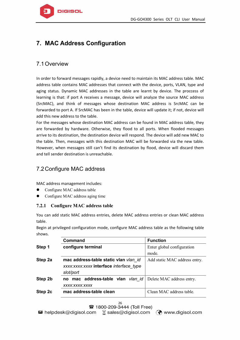
7.1 Overview
In order to forward messages rapidly, a device need to maintain its MAC address table. MAC address table contains MAC addresses that connect with the device, ports, VLAN, type and aging status. Dynamic MAC addresses in the table are learnt by device. The proccess of learning is that: if port A receives a message, device will analyze the source MAC address (SrcMAC), and think of messages whose destination MAC address is SrcMAC can be forwarded to port A. If SrcMAC has been in the table, device will update it; if not, device will add this new address to the table. For the messages whose destination MAC address can be found in MAC address table, they are forwarded by hardware. Otherwise, they flood to all ports. When flooded messages arrive to its destination, the destination device will respond. The device will add new MAC to the table. Then, messages with this destination MAC will be forwarded via the new table. However, when messages still can’t find its destination by flood, device will discard them and tell sender destination is unreachable.
7.2 Configure MAC address
MAC address management includes: Configure MAC address table Configure MAC address aging time
7.2.1 Configure MAC address table
You can add static MAC address entries, delete MAC address entries or clean MAC address table. Begin at privileged configuration mode, configure MAC address table as the following table shows. Command Function Step 1 configure terminal Enter global configuration
mode. Step 2a mac address-table static vlan vlan_id
xxxx:xxxx:xxxx interface interface_type slot/port
Add static MAC address entry.
Step 2b no mac address-table vlan vlan_id xxxx:xxxx:xxxx
Delete MAC address entry.
Step 2c mac address-table clean Clean MAC address table.

DG-GO4300 Series OLT CLI User Manual
27
Step 3 show mac address-table Show MAC address table.
Step 4 write Save configurations.
7.2.2 Configure MAC address aging time
There is aging time in device. If device doesn’t receive any message from other devices in aging time, it will delete the MAC address from MAC table. But for static MAC in the table, aging time is not effective. Begin at privileged configuration mode, configure MAC address aging time as the following table shows. Command Function Step 1 configure terminal Enter global configuration
mode. Step 2 mac address-table agingtime value Configure MAC address aging
time, range is 10-1000000s. 0s means don’t aging. Default is 300s.
Step 3 show mac address-table agingtime Show aging time.
Step 4 write Save configurations.
7.2.3 Clean MAC address table
Begin at privileged configuration mode, clean MAC address table as the following table shows.
Command Function
Step 1 configure terminal Enter global configuration mode.
Step 2 mac address-table clean Clean MAC address table.
7.2.4 Configure maximum learnt MAC enties of port
Begin at privileged configuration mode, configure maximum learnt MAC entries of port as the following table shows.
Command Function
Step 1 configure terminal Enter global configuration mode.
Step 2 interface {interface_type slot/port} Enter interface configuration mode. Step 3 mac-address mac-limit <0-16384> 0 means no limitation.
Step 4 exit Exit to global configuration mode.

DG-GO4300 Series OLT CLI User Manual
28
7.3 Show MAC address table
7.3.1 Show MAC address table
Begin at privileged configuration mode, show MAC address table as the following table shows. Command Function Step 1 configure terminal Enter global configuration
mode. Step 2a show mac address-table interface
{interface_type slot/port} Show MAC address table
basedon Ethernet port. Step 2b show mac address-table vlan vlan_id Show MAC address table
based on VLAN ID. Step 2c show mac address-table Show whole MAC address
table.
7.3.2 Show MAC address aging time
Begin at privileged configuration mode, show MAC address aging time as the following table shows. Command Function Step 1 configure terminal Enter global configuration
mode. Step 2 show mac address-table agingtime Show MAC address aging
time.
DG-GO4300 Series OLT CLI User Manual
29
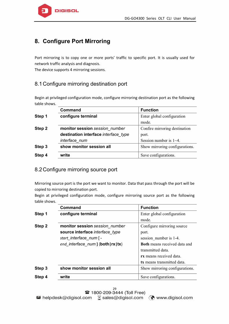
8. Configure Port Mirroring
Port mirroring is to copy one or more ports’ traffic to specific port. It is usually used for network traffic analysis and diagnosis. The device supports 4 mirroring sessions.
8.1 Configure mirroring destination port
Begin at privileged configuration mode, configure mirroring destination port as the following table shows. Command Function Step 1 configure terminal Enter global configuration
mode. Step 2 monitor session session_number
destination interface interface_type interface_num
Confire mirroring destination port. Session number is 1~4.
Step 3 show monitor session all Show mirroring configurations.
Step 4 write Save configurations.
8.2 Configure mirroring source port
Mirroring source port is the port we want to monitor. Data that pass through the port will be copied to mirroring destination port. Begin at privileged configuration mode, configure mirroring source port as the following table shows. Command Function Step 1 configure terminal Enter global configuration
mode. Step 2 monitor session session_number
source interface interface_type start_interface_num [ - end_interface_num ] {both|rx|tx}
Configure mirroring source port. session_number is 1-4. Both means received data and transmitted data. rx means received data. tx means transmitted data.
Step 3 show monitor session all Show mirroring configurations.
Step 4 write Save configurations.
DG-GO4300 Series OLT CLI User Manual
30
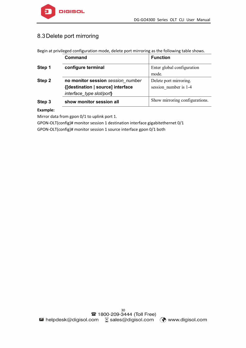
8.3 Delete port mirroring
Begin at privileged configuration mode, delete port mirroring as the following table shows.
Command Function
Step 1 configure terminal Enter global configuration mode.
Step 2 no monitor session session_number {[destination | source] interface interface_type slot/port}
Delete port mirroring. session_number is 1-4
Step 3 show monitor session all Show mirroring configurations.
Example: Mirror data from gpon 0/1 to uplink port 1. GPON-OLT(config)# monitor session 1 destination interface gigabitethernet 0/1 GPON-OLT(config)# monitor session 1 source interface gpon 0/1 both

DG-GO4300 Series OLT CLI User Manual
31
9. IGMP Configuration
9.1 IGMP Snooping
9.1.1 Enable/disable IGMP Snooping
IGMP snooping is disabled by default. You should enable by the following command. Begin at privileged configuration mode, enable/disable IGMP snooping as the following table shows. Command Function Step 1 configure terminal Enter global configuration
mode. Step 2a ip igmp snooping enable Enable IGMP Snooping.
Step 2b no ip igmp snooping Disable IGMP snooping.
Step 3 show ip igmp snooping configuration Show IGMP snooping configurations.
Step 4 write Save configurations.
9.1.2 Configure multicast data forwarding mode
Begin at privileged configuration mode, configure multicast data forwarding mode as the following table shows. Command Function Step 1 configure terminal Enter global configuration mode.
Step 2 ip igmp snooping forward vlan vlan-id
mode { flood | forward |
strict-forward}
Configure multicast data forwarding mode.
Step 3 write Save configurations.
9.1.3 Configure port multicast VLAN
After add VLAN to the port, you should also configure multicast VLAN for multicast service. Begin at privileged configuration mode, configure port multicast VLAN as the following table shows. Command Function Step 1 configure terminal Enter global configuration
mode.

DG-GO4300 Series OLT CLI User Manual
32
Step 2 interface {interface_type slot/port} Enter interface configuration mode.
Step 3a ip igmp snooping user-vlan vlan_id group-vlan vlan_id { tagged | untagged }
Configure port multicast VLAN. VLAN range is 1-4094.
Step 3b no ip igmp snooping group-vlan vlan_id
Delete port multicast VLAN.
Step 4 exit Exit to global configuration mode.
Step 5 show ip igmp snooping user-vlan Show multicast VLAN.
Step 6 write Save configurations.
9.1.4 Configure multicast router port
Multicast router port is used to forward IGMP messages. Usually, uplink port is configured as multicast router port. Begin at privileged configuration mode, configure multicast router port as the following table shows. Command Function Step 1 configure terminal Enter global configuration
mode. Step 2a ip igmp snooping mrouter vlan vlan-id
interface {interface_type slot/port} Configure multicast router port.
Step 2b no ip igmp snooping mrouter vlan vlan-id interface {interface_type slot/port}
Delete multicast router port.
Step 3 show ip igmp-snooping mrouter vlan all
Show multicast router mode configuration.
Step 4 write Save configurations.
9.1.5 Configure static multicast
Begin at privileged configuration mode, configure static multicast as the following table shows. Command Function Step 1 configure terminal Enter global configuration
mode. Step 2a ip igmp snooping static vlan vlan-id
<A.B.C.D> interface interface-id Configure static multicast.
Step 2b no ip igmp snooping static vlan vlan-id <A.B.C.D> interface interface-id
Delete static multicast.
Step 3 show ip igmp-snooping configuration Show IGMP configurations.
Step 4 write Save configurations.

DG-GO4300 Series OLT CLI User Manual
33
9.1.6 Configure fast leave
Begin at privileged configuration mode, configure fast leave as the following table shows. Command Function Step 1 configure terminal Enter global configuration
mode. Step 2 interface {interface_type slot/port} Enter interface configuration
mode. Step 3a ip igmp snooping immediate-leave Enable fast leave.
Step 3b no ip igmp snooping immediate-leave Disable fast leave.
Step 4 exit Exit to global configuration mode.
Step 5 show ip igmp snooping port information
Show port IGMP information.
Step 6 write Save configurations.
9.1.7 Configure multicast group limit
Begin at privileged configuration mode, configure multicast group limitation as the following table shows. Command Function Step 1 configure terminal Enter global configuration
mode. Step 2 interface {interface_type slot/port} Enter interface configuration
mode. Step 3a ip igmp snooping limit <0-1024> Configure port multicast group
limitation. Step 3b no ip igmp snooping limit Reset multicast group
limitation to default. Step 4 exit Exit to global configuration
mode. Step 5 show ip igmp snooping port
information Show port multicast information.
Step 6 write Save configurations.
9.1.8 Configure parameters of special query
Begin at privileged configuration mode, configure parameters of specific query as the following table shows. Command Function Step 1 configure terminal Enter global configuration

DG-GO4300 Series OLT CLI User Manual
34
mode. Step 2a ip igmp snooping
lastmember-querycount <1-255> Configure specific query count. Default is 2.
Step 2b ip igmp snooping lastmember-queryinterval <1-255>
Configure specific query interval. Default is 1s.
Step 2c ip igmp snooping lastmember-queryresponse <1-255>
Configure specific query response time. Default is 1s.
Step 3 show ip igmp snooping configuration Show IGMP configurations.
Step 4 write Save configurations.
9.1.9 Configure parameters of general query
Begin at privileged configuration mode, configure parameters of general query as the following table shows. Command Function Step 1 configure terminal Enter global configuration
mode. Step 2a ip igmp snooping general-query-packet
<enable|disable> Enable or disable general query function. Default is disable.
Step 2b ip igmp snooping general-query-time <10-255>
Configure general query interval. Default is 126s.
Step 3 show ip igmp snooping configuration Show IGMP configurations.
Step 4 write Save configurations.
9.1.10 Configure source IP of query
Begin at privileged configuration mode, configure source IP of query message as the following table shows. Command Function Step 1 configure terminal Enter global configuration mode. Step 2 ip igmp snooping member-query source-ip
<A.B.C.D> Configure source IP of query message. Default is 1.1.1.1.
Step 3 show ip igmp snooping configuration Show IGMP configurations.
Step 4 write Save configurations.
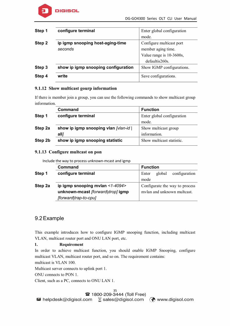
9.1.11 Configure multicast member aging time
If the port doesn’t receive any report message from member in aging time, device will delete this port from group members. Begin at privileged configuration mode, configure muticast member aging time as the following table shows. Command Function
DG-GO4300 Series OLT CLI User Manual
35
Step 1 configure terminal Enter global configuration mode.
Step 2 ip igmp snooping host-aging-time seconds
Configure multicast port member aging time. Value range is 10-3600s,
defaultis260s. Step 3 show ip igmp snooping configuration Show IGMP configurations.
Step 4 write Save configurations.
9.1.12 Show multicast gourp information
If there is member join a group, you can use the following commands to show multicast group information. Command Function Step 1 configure terminal Enter global configuration
mode. Step 2a show ip igmp snooping vlan [vlan-id |
all] Show multicast group information.
Step 2b show ip igmp snooping statistic Show multicast statistic.
9.1.13 Configure multcast on pon
Include the way to process unknown-mcast and igmp Command Function Step 1 configure terminal Enter global configuration
mode Step 2a ip igmp snooping mvlan <1-4094>
unknown-mcast [forward|drop] igmp [forward|trap-to-cpu]
Configurate the way to process mvlan and unknown multcast.
9.2 Example
This example introduces how to configure IGMP snooping function, including multicast VLAN, multicast router port and ONU LAN port, etc. 1. Requirement In order to achieve multicast function, you should enable IGMP Snooping, configure multicast VLAN, multicast router port, and so on. The requirement contains: multicast is VLAN 100. Multicast server connects to uplink port 1. ONU connects to PON 1. Client, such as a PC, connects to ONU LAN 1.
DG-GO4300 Series OLT CLI User Manual
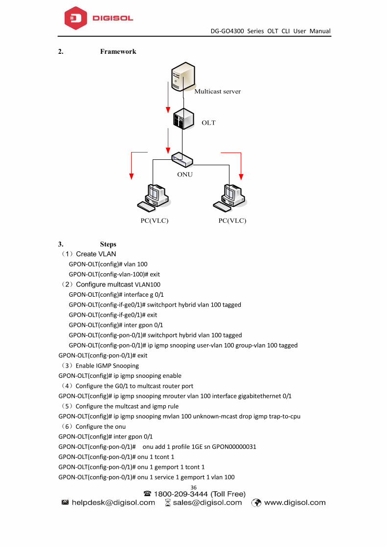
36
2. Framework
Multicast server
OLT
ONU
PC(VLC) PC(VLC)
3. Steps (1)Create VLAN
GPON-OLT(config)# vlan 100 GPON-OLT(config-vlan-100)# exit
(2)Configure multcast VLAN100 GPON-OLT(config)# interface g 0/1 GPON-OLT(config-if-ge0/1)# switchport hybrid vlan 100 tagged GPON-OLT(config-if-ge0/1)# exit GPON-OLT(config)# inter gpon 0/1 GPON-OLT(config-pon-0/1)# switchport hybrid vlan 100 tagged GPON-OLT(config-pon-0/1)# ip igmp snooping user-vlan 100 group-vlan 100 tagged
GPON-OLT(config-pon-0/1)# exit (3)Enable IGMP Snooping GPON-OLT(config)# ip igmp snooping enable (4)Configure the G0/1 to multcast router port GPON-OLT(config)# ip igmp snooping mrouter vlan 100 interface gigabitethernet 0/1 (5)Configure the multcast and igmp rule GPON-OLT(config)# ip igmp snooping mvlan 100 unknown-mcast drop igmp trap-to-cpu (6)Configure the onu GPON-OLT(config)# inter gpon 0/1 GPON-OLT(config-pon-0/1)# onu add 1 profile 1GE sn GPON00000031 GPON-OLT(config-pon-0/1)# onu 1 tcont 1 GPON-OLT(config-pon-0/1)# onu 1 gemport 1 tcont 1 GPON-OLT(config-pon-0/1)# onu 1 service 1 gemport 1 vlan 100

DG-GO4300 Series OLT CLI User Manual
37
GPON-OLT(config-pon-0/1)# onu 1 service-port 1 gemport 1 uservlan 100 vlan 100 GPON-OLT(config-pon-0/1)# onu 1 portvlan eth 1 mode hybrid def_vlan 100 GPON-OLT(config)#ip igmp snooping mvlan 100 GPON-OLT(config)#ip igmp snooping mvlan 100 receive-port gpon-onu_1/1/2:1 vport 1 GPON-OLT(config)#ip igmp snooping mvlan 100 group 224.1.1.1 to 224.1.1.10 static-port gpon-onu_1/1/2:1 vport 1
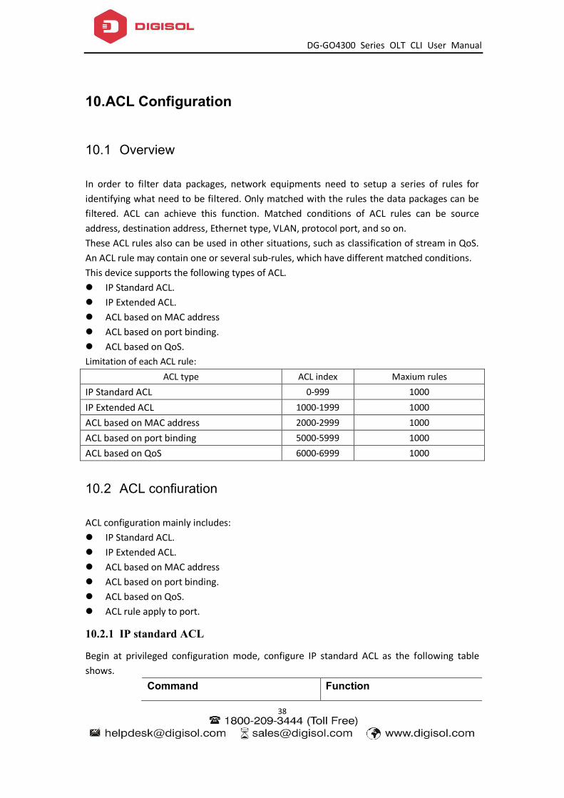
DG-GO4300 Series OLT CLI User Manual
38
10. ACL Configuration
10.1 Overview
In order to filter data packages, network equipments need to setup a series of rules for identifying what need to be filtered. Only matched with the rules the data packages can be filtered. ACL can achieve this function. Matched conditions of ACL rules can be source address, destination address, Ethernet type, VLAN, protocol port, and so on. These ACL rules also can be used in other situations, such as classification of stream in QoS. An ACL rule may contain one or several sub-rules, which have different matched conditions. This device supports the following types of ACL. IP Standard ACL. IP Extended ACL. ACL based on MAC address ACL based on port binding. ACL based on QoS. Limitation of each ACL rule:
ACL type ACL index Maxium rules IP Standard ACL 0-999 1000 IP Extended ACL 1000-1999 1000 ACL based on MAC address 2000-2999 1000 ACL based on port binding 5000-5999 1000 ACL based on QoS 6000-6999 1000
10.2 ACL confiuration
ACL configuration mainly includes: IP Standard ACL. IP Extended ACL. ACL based on MAC address ACL based on port binding. ACL based on QoS. ACL rule apply to port.
10.2.1 IP standard ACL
Begin at privileged configuration mode, configure IP standard ACL as the following table shows.
Command Function

DG-GO4300 Series OLT CLI User Manual
39
Step 1 configure terminal Enter global configuration mode.
Step 2 access-list access-list-index Enter ACL configuration mode. access-list-number is ACL index. range:0-999.
Step 3a subset ip (permit|deny) <A.B.C.D> [net-mask] subset ip (permit|deny) host <A.B.C.D> subset ip [permit|deny] any
Configure ACL rule. <A.B.C.D>: define based on source IP address and mask ACL rule. Host: define based on single IP address ACL rule. Any: define based on any source IP address ACL rule.
Step 3b No access-list access-list-index Delete the ACL
Step 4 exit Exit to global configuration mode. Step 5 show access-list
[access-list-number | all] Show ACL configurations.
Step 6 write Save configurations.
10.2.2 IP extended ACL
Begin at privileged configuration mode, configure IP extended ACL as the following table shows.
Command Function
Step 1 configure terminal Enter global configration mode. Step 2 access-list access-list-index Enter ACL configuration mode.
access-list-number is ACL index. range:1000-1999.
Step 3a subset protocol {deny | permit} protocol { <A.B.C.D> net-mask {<A.B.C.D> net-mask | host <A.B.C.D> | any }[match {dscp priority| precedence priority | tos priority}] [set {dscp priority| precedence priority | tos priority}]
Configure IP extended ACL rule. Parameter protocol should be icmp, igmp, igrp, ip, ospf, pim, tcp, or udp, etc. it also can be replaced by protocol code 0~255.
Step 3b no access-list access-list-index Delete ACL
Step 4 exit Exit global configuration mode. Step 5 show access-list [access-list-number |
all ] Show ACL configurations.
Step 6 write Save configurations.
10.2.3 ACL based on MAC address

DG-GO4300 Series OLT CLI User Manual
40
Begin at privileged configuration mode, configure ACL based on MAC address as the following table shows.
Command Function
Step 1 configure terminal Enter global configuration mode. Step 2 access-list access-list-number Enter ACL configuration mode.
access-list-number is ACL index. range:2000-2999.
Step 3a subset ethernet [permit|deny] [source] <xx:xx:xx:xx:xx:xx> <xx:xx:xx:xx:xx:xx> {[dest] <xx:xx:xx:xx:xx:xx> <xx:xx:xx:xx:xx:xx>}*1 {[vlan] <1-4094>}*1 {[cos] <0-7>}*1 {[ethernet-type] <XXXX> <XXXX>
Configure IP extended ACL rule.
Step 3b no access-list access-list-index Delete ACL
Step 4 exit Exit to global configuration mode. Step 5 show access-list [access-list-number |
all] Show ACL configurations.
Step 6 write Save configurations.
10.2.4 ACL based on port binding
This type of ACL includes the other types. Begin at privileged configuration mode, configure ACL based on port binding as the following table shows.
Command Function
Step 1 configure terminal Enter global configuration mode. Step 2 access-list access-list-number Enter ACL configuration mode.
access-list-number is ACL index. range:5000-5999;
Step 3a subset port-business [permit|deny] {src-ip |dest-ip | protocol | tos-dscp | src-mac | dest-mac | vlan | cos | ethernet-type | src-port | dest-port}
Permit:Permit data stream which match the rule passing through. Deny:Do not permit data stream which match the rule passing through. src-ip : source IP address dest-ip:destination IP address protocol:IP protocol type tos-dscp:IP priority src-mac:source MAC address dest-mac:destination MAC address

DG-GO4300 Series OLT CLI User Manual
41
vlan:VLAN IAD cos:802.1p priority ethernet-type:ethernet type src-port:Layer 4 source port dest-port:Layer 4 destination port
Step 3b no access-list access-list-index Delete ACL
Step 4 exit Exit to global configuration mode. Step 5 show access-list access-list-number Show ACL configurations.
Step 6 write Save configurations.
10.2.5 ACL based on QoS
Begin at privileged configuration mode, configure ACL based on QoS as the following table shows.
Command Function
Step 1 configure terminal Enter global configuration mode. Step 2 access-list access-list-number Enter ACL configuration mode.
access-list-number is ACL index. range:6000-6999.
Step 3a subset qos <0-8> <0-7> <1-12> <0-8>: output priority <0-7>: output queue <1-12>: rule priority
Step 3b subset qos {src-ip |dest-ip | protocol | tos-dscp | src-mac | dest-mac | vlan | cos | ethernet-type | src-port | dest-port}
src-ip : source IP address dest-ip: destination IP address protocol: IP protocol type tos-dscp: IP priority src-mac: source MAC address dest-mac: destination MAC address vlan: VLAN ID cos:802.1p priority ethernet-type: Ethernet type src-port:Layer 4 source port dest-port:Layer 4 destination port
Step 3c no access-list access-list-number Deleting ACL rule. Only the ACL that have not been applied can be deleted.
Step 4 exit Exit to global configuration mode. Step 5 show access-list access-list-number Show ACL configurations.

DG-GO4300 Series OLT CLI User Manual
42
Step 6 write Save configurations.
10.2.6 ACL rule apply to port
Begin at privileged configuration mode, apply ACL rule to port as the following table shows. Command Function Step 1 configure terminal Enter globle configuration mode. Step 2 interface {interface_type slot/port} Enter interface configuration mode.
Step 3a ip access-group access-list-number in Apply ACL rule to port.
Step 3b no ip access-group access-list-number in
Delete ACL rule from port.
Step 4 exit Exit to glogbal configuration mode.
Step 5 show access-list access-list-number Show ACL configurations.
Step 6 write Save configurations.
10.3 Example
(1)Deny specific IP address packets passing through PON1 denies packets which source IP is 192.168.100.10 passing through.
GPON-OLT(config)# access-list 5000 GPON-OLT(config-bsn-acl-5000)# subset port-business deny src-ip 192.168.100.10 255.255.255.255 GPON-OLT(config-bsn-acl-5000)# exit GPON-OLT(config)# interface gpon 0/1 GPON-OLT(config-pon-0/1)# ip access-group 5000 in
(2)Permit specific MAC address packets passing through PON1 permits IP packets which source MAC is b8:97:5a:72:37:8d passing through. GPON-OLT(config)#access-list 2000
GPON-OLT(config-eth-acl-2000)# subset ethernet deny ethernet-type 0800 ffff GPON-OLT(config-eth-acl-2000)#exit GPON-OLT(config)# access-list 2001 GPON-OLT(config-eth-acl-2001)# subset ethernet permit source b8:97:5a:72:37:8d ff:ff:ff:ff:ff:ff GPON-OLT(config-eth-acl-2001) # exit GPON-OLT(config)# interface gpon 0/1 GPON-OLT(config-pon-0/1)# ip access-group 2000 in GPON-OLT(config-pon-0/1)# ip access-group 2001 in GPON-OLT(config-pon-0/1)#exit

DG-GO4300 Series OLT CLI User Manual
43

DG-GO4300 Series OLT CLI User Manual
44
11. QoS Configuration
11.1 Configure queue scheduling mode
Queue scheduling mode contains strict priority, weighted round robin and hybrid mode. This device supports 8 queues altogether. Begin at privileged configuration mode, configure queue scheduling mode as the following table shows. Command Function Step 1 configure terminal Enter global configuration
mode. Step 2a queue-scheduler strict-priority Configure strict priority
scheduling mode. Step 2b queue-scheduler wrr [queue0 queue1
queue2 queue3 queue4 queue5 queue6 queue7]
Configure weighted round robin scheduling mode. Queuex is weight of queue x, range is 1-127. By default, weights of queue 0~7 are 1, 1, 2, 2, 4, 4, 8, 8.
Step 2c queue-scheduler sp-wrr [queue0 queue1 queue2 queue3 queue4 queue5 queue6 queue7]
Configure hybrid scheduling mode. Queuex is weight of queue x, range is 0-127. If it is set to be 0, the queue is strict priority queue. By default, weights of queue 0~7 are 1, 1, 2, 2, 4, 4, 8, 8.
Step 3 show queue-scheduler Show queue scheduling configurations.
Step 4 write Save configurations.
11.2 Configure queue mapping
Begin at privileged configuration mode, configure queue mapping as the following table shows. Command Function Step 1 configure terminal Enter global configuration
mode.

DG-GO4300 Series OLT CLI User Manual
45
Step 2 queue-scheduler tc priority queue queue Configure mapping relation between queues and priority. By default, priority 0~7 maps to queue 0~7 respectively.
Step 3 show queue-scheduler priority mapping
Show queue mapping.
Step 4 write Save configurations.

DG-GO4300 Series OLT CLI User Manual
46
12. STP Configuration
12.1 STP default settings
STP default settings: Speciality Default value Enable status STP disabled Bridge priority 32768 STP port priority 128 STP port cost 10-Gigabit Ethernet :2
Gigabit Ethernet :4 Fast Ethernet :19 Ethernet :100
Hello time 2s Forward delay time 15s Maxmum aging time 20s Mode RSTP
12.2 Cofigure STP
STP configurations mainly contain: Enable device’s STP function. Enable port’s STP function. Configure STP mode. Configure bridge priority of device. Configure forward delay of device. Configure hello time of device. Configure max age of designated device. Configure priority of designated port. Configure path cost of designated port.
12.2.1 Enable device’s STP function
Begin at privileged configuration mode, enable device’s STP function as the following table shows. Command Function Step 1 configure terminal Enter global configuration mode. Step 2a spanning-tree on Enable device’s STP function.
By default, STP function is

DG-GO4300 Series OLT CLI User Manual
47
disabled. Step 2b no spanning-tree Disable device’s STP function.
Step 3 show spanning-tree Show STP configurations.
Step 4 write Save configurations.
12.2.2 Enable port STP
In order to work flexibly, you can disable some specific ports’ STP function. Begin at privileged configuration mode, enable port’s STP function as the following table shows. Command Function Step 1 configure terminal Enter global configuration
mode. Step 2 interface {interface_type slot/port} Enter interface configuration
mode. Step 3a spanning-tree on Enable port’s STP function.
Step 3b no spanning-tree on Disable port’s STP function.
Step 4 exit Exit to global configuration mode.
Step 5 show spanning-tree interface {interface_type slot/port}
Show port’s STP configurations.
Step 6 write Save configurations.
12.2.3 Configure spanning tree mode
This device supports STP and RSTP. By default, it runs RSTP. You can choose RTP manually. Begin at privileged configuration mode, configure spanning tree mode as the following table shows. Command Function Step 1 configure terminal Enter global configuration
mode. Step 2 spanning-tree mode [rstp | stp] Configure spanning tree mode.
It runs RSTP by default. Step 3 show spanning-tree Show STP configurations.
Step 4 write Save configurations.
12.2.4 Configure bridge priority
Device’s bridge priority decides if it will be selected as root of spanning tree. Begin at privileged configuration mode, configure device’s bridge prority as the following table shows.

DG-GO4300 Series OLT CLI User Manual
48
Command Function Step 1 configure terminal Enter global configuration
mode. Step 2 spanning-tree priority bridge-priority Configure device’s bridge
priority. Priority range is 0~65535, default is 32768.
Step 3 show spanning-tree Show STP configurations.
Step 4 write Save configurations.
12.2.5 Configure forward delay
Network will recompute spanning tree when there is link down in network. Construction of spanning tree will be changed too. But the new STP PDU can’t go the rounds of network. In this case, a temporary loop will come out if the new root port and designated port forward data immediately. So, STP adopts state transition mechanism. Before re-forwarding data, root port and designated port will undergo an intermediate state. After forward delay time out in the intermediate state, the new STP PDU have gone the rounds of network, then root port and designated port begin to forward data. Begin at privileged configuration mode, configure device’s forward delay as the following table shows. Command Function Step 1 configure terminal Enter global configuration
mode. Step 2 spanning-tree forward-time seconds Configure device’s forward
delay. bridge-priority range is 4~30, default is 15.
Step 3 show spanning-tree Show STP configurations.
Step 4 write Save configurations.
Forward Delay has something to do with that how big the network is. Generally, the bigger the network, the longer forward delay should be configured. If forward delay is too small, there may be temporary redundant path; while it is too big, network will take more time to resume connectivity. We suggest using default value if you have no idea about this. Notice: Hello time, forward delay and maximum age are time parameters of root device. These three parameters should meet the following formula, otherwise, the network will not stable. 2 × (forward-delay -1) >= maximum-agemaximum-age >= 2 × (hello + 1) The unit of “1” in formula is second.
12.2.6 Configure hello time

DG-GO4300 Series OLT CLI User Manual
49
Network Bridge will send hello message to other surrounding network bridge at regular intervals for verifying link connectivity. A suitable hello time can ensure a device find link failure in time and not occupy more network resource. If hello time is too big, device will be in mistake for link failure when loss packets. Then network device recomputes spanning tree. While if too small, network device sends repeated STP PDU frequently. This will increase device’s load and waste network resource. Begin at privileged configuration mode, configure device’s hello time as the following table shows. Command Function Step 1 configure terminal Enter global configuration
mode. Step 2 spanning-tree hellotime seconds Configure device’s hello time.
Hello time range is 1~10, default is 2.
Step 3 show spanning-tree Show STP configurations.
Step 4 write Save configurations.
12.2.7 Configure max age time
Max age time is maximum life time of configuration message. When message age is biger than maximum age, configuration message will be discarded. Begin at privileged configuration mode, configure maximum age as the following table shows. Command Function Step 1 configure terminal Enter global configuration
mode. Step 2 spanning-tree max-age seconds Configure maximum age of
device. max age range is 6-40, default is 20.
Step 3 show spanning-tree Show STP configurations.
Step 4 write Save configurations.
12.2.8 Configure priority of designated port
Port priority decides whether it can be selected as root port or not. On equal conditions, the higher priority port will be selected as root port. Generally, the priority value is smaller, the port has higher priority. If all ports’ priority value are the same, their priority decided by their port index. Begin at privileged configuration mode, configure priority of designated port as the following table shows. Command Function

DG-GO4300 Series OLT CLI User Manual
50
Step 1 configure terminal Enter global configuration mode.
Step 2 interface {interface_type slot/port} Enter interface configuration mode.
Step 3 spanning-tree port-priority priority Configure priority of designated port. priority range is 1-255, default is 128.
Step 4 exit Exit to global configuration mode.
Step 5 show spanning-tree interface {interface_type slot/port}
Show port STP configurations.
Step 6 write Save configurations.
12.2.9 Configure path cost of designated port
Path Cost is related to the speed of the link connected to the port. On the STP switch, a port can be configured with different path costs. Begin at privileged configuration mode, configure path cost of designated port as the following table shows. Command Function Step 1 configure terminal Enter global configuration mode. Step 2 interface {interface_type slot/port} Enter interface configuration
mode. Step 3 spanning-tree cost value Configure path cost of designated
port. Path cost range is 1-65535, default is auto.
Step 4 exit Exit to global configuration mode.
Step 5 show spanning-tree interface {interface_type slot/port}
Show port STP configurations.
Step 6 write Save configurations.
12.2.10 Configure edge port
The port which connects with terminal host is Edge Port. In process of spanning tree recomputation, edge port can transfer to forwarding status derectly so that it can reduce transfer time. Because RSTP can’t detect whether the port is edge port or not, if the port doesn’t connect with switch, you’d better configure it as edge port. But when the port connects with a switch, RSTP can detect and configure it as non-edge port. By default, all ports are configured as non-edged port. Begin at privileged configuration mode, configure edge port as the following table shows.
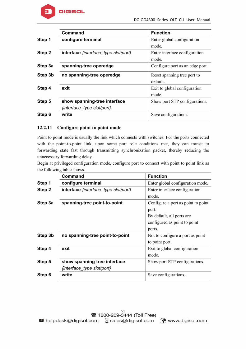
DG-GO4300 Series OLT CLI User Manual
51
Command Function Step 1 configure terminal Enter global configuration
mode. Step 2 interface {interface_type slot/port} Enter interface configuration
mode. Step 3a spanning-tree operedge Configure port as an edge port.
Step 3b no spanning-tree operedge Reset spanning tree port to default.
Step 4 exit Exit to global configuration mode.
Step 5 show spanning-tree interface {interface_type slot/port}
Show port STP configurations.
Step 6 write Save configurations.
12.2.11 Configure point to point mode
Point to point mode is usually the link which connects with switches. For the ports connected with the point-to-point link, upon some port role conditions met, they can transit to forwarding state fast through transmitting synchronization packet, thereby reducing the unnecessary forwarding delay. Begin at privileged configuration mode, configure port to connect with point to point link as the following table shows. Command Function Step 1 configure terminal Enter global configuration mode. Step 2 interface {interface_type slot/port} Enter interface configuration
mode. Step 3a spanning-tree point-to-point Configure a port as point to point
port. By default, all ports are configured as point to point ports.
Step 3b no spanning-tree point-to-point Not to configure a port as point to point port.
Step 4 exit Exit to global configuration mode.
Step 5 show spanning-tree interface {interface_type slot/port}
Show port STP configurations.
Step 6 write Save configurations.

DG-GO4300 Series OLT CLI User Manual
52
12.3 Show STP information
After configuring, use the following commands to show STP information. Command Function show spanning-tree Show STP configurations and
running status. show spanning-tree interface {interface_type slot/port}
Show STP configurations and running status of a port.

DG-GO4300 Series OLT CLI User Manual
53
13. Static Route Configuration
Static route is usually used in a simple network. This device supports maximum 512 static route rules.
Command Function
Step 1 configure terminal Enter global configuration mode.
Step 2a ip route A.B.C.D A.B.C.D A.B.C.D Add static route rule. Step 2b ip route A.B.C.D/M A.B.C.D Add static route rule. Step 3a no ip route A.B.C.D A.B.C.D A.B.C.D Delete static route rule. Setp 3b no ip route A.B.C.D/M A.B.C.D Delete static route rule. Step 4 show ip route Show route rules.

DG-GO4300 Series OLT CLI User Manual
54
14. IP Management Configuration
14.1 Configure outband management
Port AUX is outband management port. So its IP is outband management IP.
14.1.1 Enter AUX port configuration mode
Begin at privileged configuration mode, enter interface configuration mode as the following table shows.
Command Function
Step 1 configure terminal Enter global configuration mode.
Step 2 interface aux Enter AUX interface.
14.1.2 Configure outband management IP address and mask
Begin at privileged configuration mode, configure outband management IP address and mask as the following table shows.
Command Function
Step 1 config terminal Enter global configuration mode.
Step 2 interface aux Enter AUX interface.
Step 3a ip address <A.B.C.D> net-mask Configure IP address and mask of AUX port.
Step 3b no aux ip address Reset outband management IP to default.
Step 4 exit Exit to global configuration mode.
Step 5 show aux ip address Show outband management IP.
Step 6 write Save configurations.
14.1.3 Show AUX port information
Begin at privileged configuration mode, show AUX port information as the following table shows.
Command Function
Step 1 configure terminal Enter global configuration mode.

DG-GO4300 Series OLT CLI User Manual
55
Step 2 show interface aux Show AUX port information.
14.2 Configure inband management
This device provides inband management which can be managed from uplink port. Begin at privileged configuration mode, configure inband management IP address and mask as the following table shows.
Command Function
Step 1 config terminal Enter global configuration mode.
Step 2 vlan vlan_id Create VLAN. Step 3 exit Exit to global configuration
mode. Step 4 interface vlan vlan_id
Enter VLAN interface configuration mode. vlan_id range is 1-4094.
Step 5a ip address <A.B.C.D> net-mask Configure IP address and mask.
Step 5b no ip address <A.B.C.D> Delete IP address and mask.
Step 6 exit Exit to global configuration mode.
Step 7 show interface vlan vlan_id Show VLAN information.
Step 8 write Save configurations.
14.3 Confgure manangement gateway
When OLT management IP and management server are not in the same network segment, it needs to configure a gateway. Begin at privileged configuration mode, configure management gateway as the following table shows.
Command Function
Step 1 config terminal Enter global configuration mode.
Step 2 ip route 0.0.0.0/0 <A.B.C.D> Configure management gateway.
Step 3 no ip route 0.0.0.0/0 <A.B.C.D> Delete management gateway.
Step 4 show ip route Show management gateway configuration.

DG-GO4300 Series OLT CLI User Manual
56
Step 5 write Save configurations.

DG-GO4300 Series OLT CLI User Manual
57
14.4 Confgure DNS
It can configure two DNS server
Command Function
Step 1 config terminal Enter global configuration mode.
Step 2 ip dns <A.B.C.D> {<A.B.C.D>} Configure DNS
Step 3 show ip dns Show management gateway.
Step 4 write Save configurations.
15. ARP Proxy
In order to achieve interconnection between ONU in the same PON, the devices added the ARP Proxy function.
Command Function
Step 1 config terminal Enter global configuration mode.
Step 2 interface vlan vlan_id
Create vlan and enter to vlan interface
Step 3a ip proxy-arp Enable ARP Proxy
Step 3b no ip proxy-arp Disable ARP Proxy

DG-GO4300 Series OLT CLI User Manual
58
16. DHCP Management Configuration
16.1 Configure DHCP server
Now,larger and larger number of IP address are needed to allocate .DHCP (Dynamic Host configuration Protocol) is created to solve this problem .It concludes DHCP Server and DHCP Client.Requested by client, IP address are allocated by the server.Configure DHCP Server as the following table show:
Command Function
Step 1 config terminal Enter global configuration mode.
Step 2a dhcp-server [enable | disable] Disable the DHCP server function
Step 2b dhcp-server | dns1 | dns2 | dns3 | wins] <A.B.C.D>
Configure DHCP's DNS and WINS Server
Step 2c dhcp-server startip A.B.C.D endip A.B.C.D
Configure DHCP IP address pool
Step 2d dhcp-server subnet A.B.C.D Configure DHCP mask
Step 2e dhcp-server gateway A.B.C.D Configure DHCP gateway
Step 2f dhcp-server interface vlan <1-4095> Add the VLAN to the DHCP Server(If want DHCP server successful,need to configure the vlan interface IP address)
Step 2g dhcp-server leasetime leasetime Configure IP address leasetime
Step 3a show dhcp-server Show DHCP server configuration
Step 3d show dhcp-server lease Show DHCP Server allocate IP address
Step 4 copy running-config startup-config Save the configuration
16.2 Configure DHCP relay
Because the DHCP receiving need to broadcast ,so the server and the client should be in the same network.The DHCP relay can save this issue effective. Configure DHCP relay as the following table show:
1.Single DHCP relay configuration:
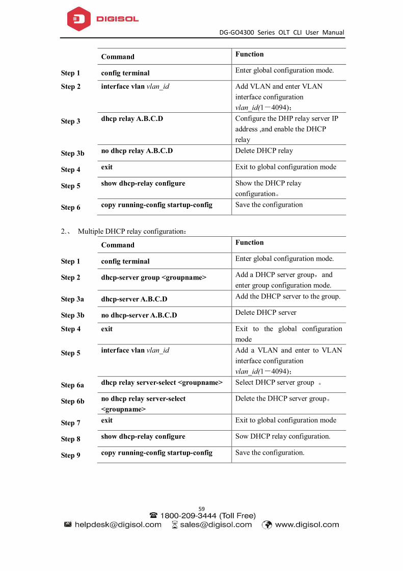
DG-GO4300 Series OLT CLI User Manual
59
Command Function
Step 1 config terminal Enter global configuration mode.
Step 2 interface vlan vlan_id Add VLAN and enter VLAN interface configuration vlan_id(1-4094);
Step 3 dhcp relay A.B.C.D Configure the DHP relay server IP address ,and enable the DHCP relay
Step 3b no dhcp relay A.B.C.D Delete DHCP relay
Step 4 exit Exit to global configuration mode
Step 5 show dhcp-relay configure Show the DHCP relay configuration。
Step 6 copy running-config startup-config Save the configuration
2.、 Multiple DHCP relay configuration:
Command Function
Step 1 config terminal Enter global configuration mode.
Step 2 dhcp-server group <groupname> Add a DHCP server group,and enter group configuration mode.
Step 3a dhcp-server A.B.C.D Add the DHCP server to the group.
Step 3b no dhcp-server A.B.C.D Delete DHCP server
Step 4 exit Exit to the global configuration mode
Step 5 interface vlan vlan_id Add a VLAN and enter to VLAN interface configuration vlan_id(1-4094);
Step 6a dhcp relay server-select <groupname> Select DHCP server group 。
Step 6b no dhcp relay server-select <groupname>
Delete the DHCP server group。
Step 7 exit Exit to global configuration mode
Step 8 show dhcp-relay configure Sow DHCP relay configuration.
Step 9 copy running-config startup-config Save the configuration.
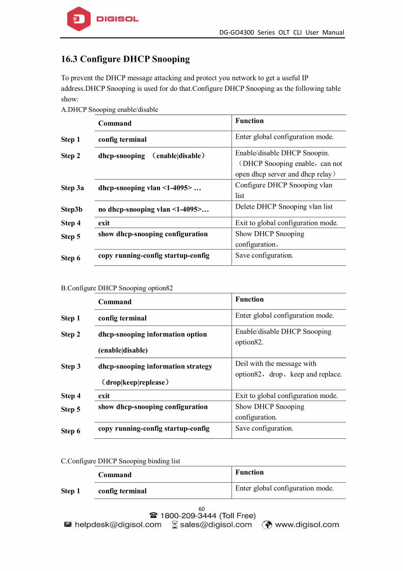
DG-GO4300 Series OLT CLI User Manual
60
16.3 Configure DHCP Snooping
To prevent the DHCP message attacking and protect you network to get a useful IP address.DHCP Snooping is used for do that.Configure DHCP Snooping as the following table show: A.DHCP Snooping enable/disable
Command Function
Step 1 config terminal Enter global configuration mode.
Step 2 dhcp-snooping (enable|disable) Enable/disable DHCP Snoopin.(DHCP Snooping enable,can not open dhcp server and dhcp relay)
Step 3a dhcp-snooping vlan <1-4095> … Configure DHCP Snooping vlan list
Step3b no dhcp-snooping vlan <1-4095>… Delete DHCP Snooping vlan list
Step 4 exit Exit to global configuration mode.
Step 5 show dhcp-snooping configuration Show DHCP Snooping configuration。
Step 6 copy running-config startup-config Save configuration.
B.Configure DHCP Snooping option82
Command Function
Step 1 config terminal Enter global configuration mode.
Step 2 dhcp-snooping information option
(enable|disable)
Enable/disable DHCP Snooping option82.
Step 3 dhcp-snooping information strategy
(drop|keep|replease)
Deil with the message with option82,drop、keep and replace.
Step 4 exit Exit to global configuration mode.
Step 5 show dhcp-snooping configuration Show DHCP Snooping configuration.
Step 6 copy running-config startup-config Save configuration.
C.Configure DHCP Snooping binding list
Command Function
Step 1 config terminal Enter global configuration mode.
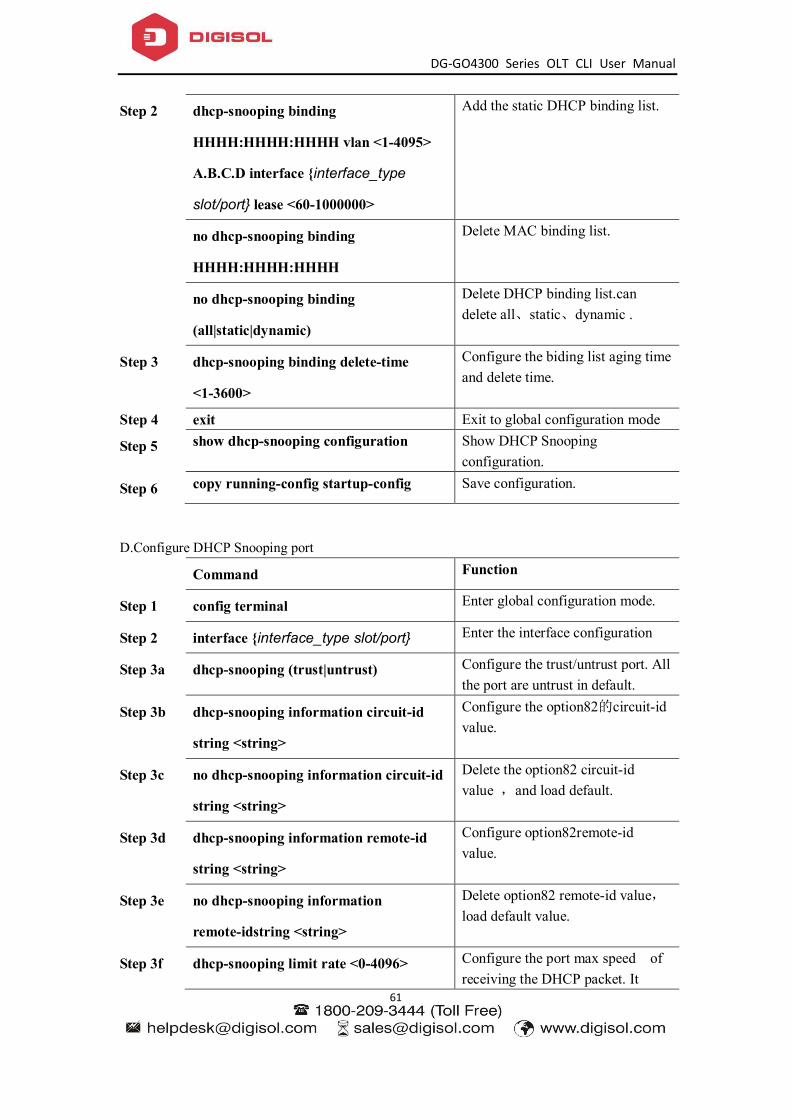
DG-GO4300 Series OLT CLI User Manual
61
Step 2 dhcp-snooping binding
HHHH:HHHH:HHHH vlan <1-4095>
A.B.C.D interface {interface_type
slot/port} lease <60-1000000>
Add the static DHCP binding list.
no dhcp-snooping binding
HHHH:HHHH:HHHH
Delete MAC binding list.
no dhcp-snooping binding
(all|static|dynamic)
Delete DHCP binding list.can delete all、static、dynamic .
Step 3 dhcp-snooping binding delete-time
<1-3600>
Configure the biding list aging time and delete time.
Step 4 exit Exit to global configuration mode
Step 5 show dhcp-snooping configuration Show DHCP Snooping configuration.
Step 6 copy running-config startup-config Save configuration.
D.Configure DHCP Snooping port
Command Function
Step 1 config terminal Enter global configuration mode.
Step 2 interface {interface_type slot/port} Enter the interface configuration
Step 3a dhcp-snooping (trust|untrust) Configure the trust/untrust port. All the port are untrust in default.
Step 3b dhcp-snooping information circuit-id
string <string>
Configure the option82的circuit-id value.
Step 3c no dhcp-snooping information circuit-id
string <string>
Delete the option82 circuit-id value ,and load default.
Step 3d dhcp-snooping information remote-id
string <string>
Configure option82remote-id value.
Step 3e no dhcp-snooping information
remote-idstring <string>
Delete option82 remote-id value,load default value.
Step 3f dhcp-snooping limit rate <0-4096> Configure the port max speed of receiving the DHCP packet. It
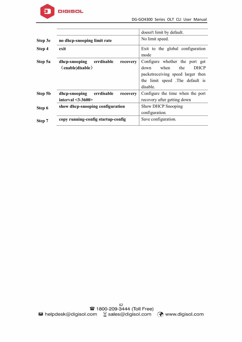
DG-GO4300 Series OLT CLI User Manual
62
doesn't limit by default.
Step 3e no dhcp-snooping limit rate No limit speed.
Step 4 exit Exit to the global configuration mode
Step 5a dhcp-snooping errdisable recovery (enable|disable)
Configure whether the port get down when the DHCP packetreceiving speed larger then the limit speed .The default is disable.
Step 5b dhcp-snooping errdisable recovery interval <3-3600>
Configure the time when the port recovery after getting down
Step 6 show dhcp-snooping configuration Show DHCP Snooping configuration.
Step 7 copy running-config startup-config Save configuration.

DG-GO4300 Series OLT CLI User Manual
63
17. PON Management Configuration
17.1 Show PON port info and optical power
17.1.1 Show Pon port statistics
Command Function Step 1 configure terminal Enter global configuration
mode. Step 2 interface gpon slot/port Enter PON interface
configuration mode. Step 3 show pon statistics Show PON port statistics.
17.1.2 Show PON port optical power
Optical module parameters contain transmit optical power, receive optical power, temperature, voltage and bias current. These 5 parameters decide whether the optical module can work normal or not. Any of them is abnormal may cause ONU deregister or lose packets. Begin at privileged configuration mode, show PON port optical module parameters as the following table shows.
Command Function
Step 1 configure terminal Enter global configuration mode.
Step 2 interface gpon slot/port Enter PON interface configuration mode.
Step 3 show pon optical transceiver Show pon optical parameters.
17.1.3 Show ONU optical transceiver
Command Function
Step 1 configure terminal Enter global configuration mode.
Step 2 interface gpon slot/port Enter PON interface configuration mode.
Step 3 show pon onu [<1-128>|all] rx-power Show ONU optical transceiver

DG-GO4300 Series OLT CLI User Manual
64
17.2 PON port configuration
17.2.1 Enable/Disable PON
Begin at privileged configuration mode, enable or disable PON port as the following table shows.
Command Function
Step 1 configure terminal Enter global configuration mode.
Step 2 interface gpon slot/port Enter PON interface configuration mode.
Step 3a Shutdown Disable pon port Step 3b No shutdown Enable pon port Step 4 show pon info Show pon info
17.3 ONU auto-learn configuration
打开或者关闭 PON 口的 ONU 自动授权功能。
Command Function
Step 1 configure terminal Enter global configuration mode.
Step 2 interface gpon slot/port Enter PON interface configuration mode.
Step 3a onu auto-learn {default-onu-profile <profile_name>}*1
Enable the auto-learn function.It support to select onu profile.will bind the default profile if not select.
Step 3b no onu auto-learn Disable the auto-learn Step 4 show onu auto-learn Show the auto-learn
Note: After the ONU is auto-learned, there will be ONU connected to this PON port. The
OLT will check whether there is equipment ID in the auto-binding list. If the equipment ID of this ONU is in the auto-binding list, the ONU uses the information of auto-binding list to register.

DG-GO4300 Series OLT CLI User Manual
65
18. ONU Management Configuration
18.1 ONU basic configuration
18.1.1 Show auto-find ONU
Command Function
Step 1 configure terminal Enter global configuration mode.
Step 2 interface gpon slot/port Enter PON interface configuration mode.
Step 3 Show onu auto-find Show auto-find ONU show onu auto-find {[detail-info]}*1 Show auto-find ONU detail
info
18.1.2 ONU automatic authorize
OLT can enable/disable automatic authorized mode. ONU will authorized automatically when ONU online
Command Function
Step 1 configure terminal Enter global configuration mode.
Step 2 interface gpon slot/port Enter PON interface configuration mode.
Step 3 onu auto-learn {default-onu-profile <profile_name>}*1
Enable/disable auto-auth
Step 4 Show onu auto-learn Show auto-learn
18.1.3 Show ONU authorized info
Command Function
Step 1 configure terminal Enter global configuration mode.
Step 2 interface gpon slot/port Enter PON interface configuration mode.
Step 3 Show onuinfo [<1-128>]*1 Show ONU authorized info
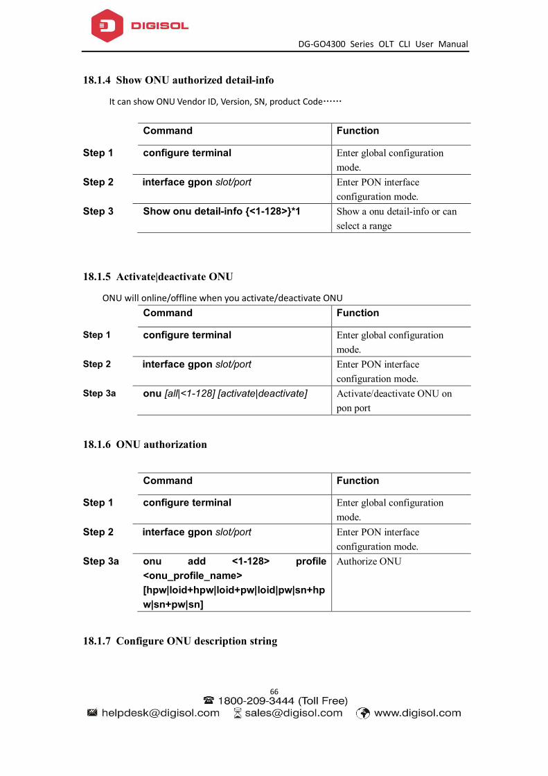
DG-GO4300 Series OLT CLI User Manual
66
18.1.4 Show ONU authorized detail-info
It can show ONU Vendor ID, Version, SN, product Code……
Command Function
Step 1 configure terminal Enter global configuration mode.
Step 2 interface gpon slot/port Enter PON interface configuration mode.
Step 3 Show onu detail-info {<1-128>}*1 Show a onu detail-info or can select a range
18.1.5 Activate|deactivate ONU
ONU will online/offline when you activate/deactivate ONU
Command Function
Step 1 configure terminal Enter global configuration mode.
Step 2 interface gpon slot/port Enter PON interface configuration mode.
Step 3a onu [all|<1-128] [activate|deactivate] Activate/deactivate ONU on pon port
18.1.6 ONU authorization
Command Function
Step 1 configure terminal Enter global configuration mode.
Step 2 interface gpon slot/port Enter PON interface configuration mode.
Step 3a onu add <1-128> profile <onu_profile_name> [hpw|loid+hpw|loid+pw|loid|pw|sn+hpw|sn+pw|sn]
Authorize ONU
18.1.7 Configure ONU description string
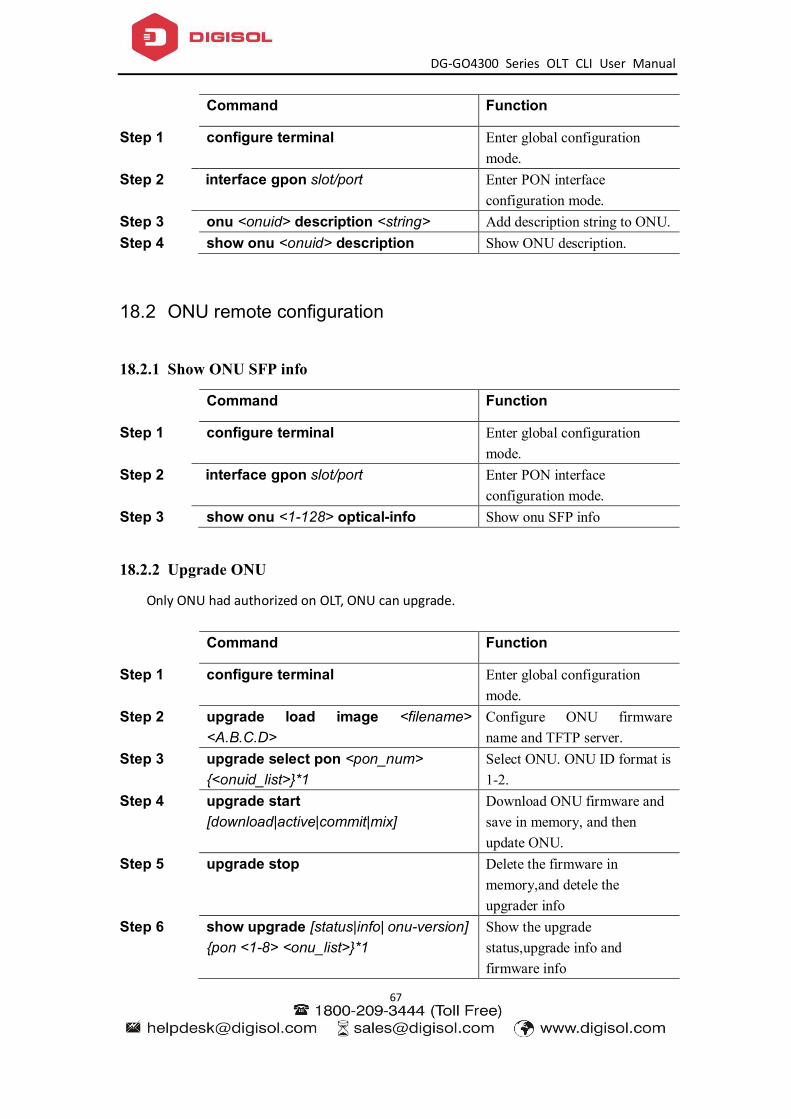
DG-GO4300 Series OLT CLI User Manual
67
Command Function
Step 1 configure terminal Enter global configuration mode.
Step 2 interface gpon slot/port Enter PON interface configuration mode.
Step 3 onu <onuid> description <string> Add description string to ONU. Step 4 show onu <onuid> description Show ONU description.
18.2 ONU remote configuration
18.2.1 Show ONU SFP info
Command Function
Step 1 configure terminal Enter global configuration mode.
Step 2 interface gpon slot/port Enter PON interface configuration mode.
Step 3 show onu <1-128> optical-info Show onu SFP info
18.2.2 Upgrade ONU
Only ONU had authorized on OLT, ONU can upgrade.
Command Function
Step 1 configure terminal Enter global configuration mode.
Step 2 upgrade load image <filename> <A.B.C.D>
Configure ONU firmware name and TFTP server.
Step 3 upgrade select pon <pon_num> {<onuid_list>}*1
Select ONU. ONU ID format is 1-2.
Step 4 upgrade start [download|active|commit|mix]
Download ONU firmware and save in memory, and then update ONU.
Step 5 upgrade stop Delete the firmware in memory,and detele the upgrader info
Step 6 show upgrade [status|info| onu-version] {pon <1-8> <onu_list>}*1
Show the upgrade status,upgrade info and firmware info
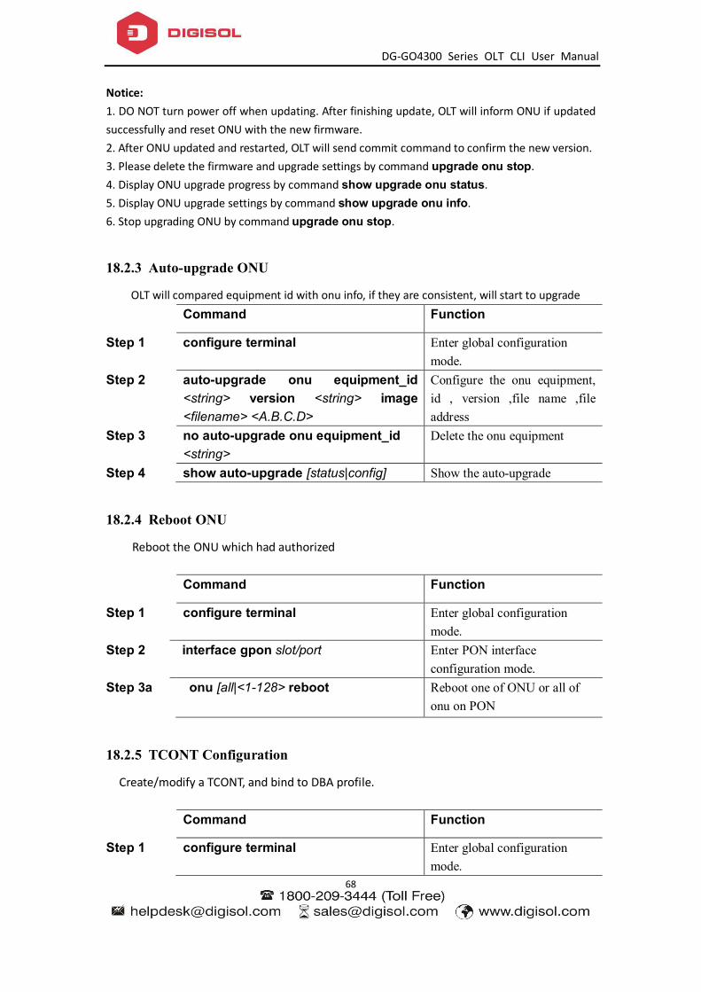
DG-GO4300 Series OLT CLI User Manual
68
Notice: 1. DO NOT turn power off when updating. After finishing update, OLT will inform ONU if updated successfully and reset ONU with the new firmware. 2. After ONU updated and restarted, OLT will send commit command to confirm the new version. 3. Please delete the firmware and upgrade settings by command upgrade onu stop. 4. Display ONU upgrade progress by command show upgrade onu status. 5. Display ONU upgrade settings by command show upgrade onu info. 6. Stop upgrading ONU by command upgrade onu stop.
18.2.3 Auto-upgrade ONU
OLT will compared equipment id with onu info, if they are consistent, will start to upgrade
Command Function
Step 1 configure terminal Enter global configuration mode.
Step 2 auto-upgrade onu equipment_id <string> version <string> image <filename> <A.B.C.D>
Configure the onu equipment, id , version ,file name ,file address
Step 3 no auto-upgrade onu equipment_id <string>
Delete the onu equipment
Step 4 show auto-upgrade [status|config] Show the auto-upgrade
18.2.4 Reboot ONU
Reboot the ONU which had authorized
Command Function
Step 1 configure terminal Enter global configuration mode.
Step 2 interface gpon slot/port Enter PON interface configuration mode.
Step 3a onu [all|<1-128> reboot Reboot one of ONU or all of onu on PON
18.2.5 TCONT Configuration
Create/modify a TCONT, and bind to DBA profile.
Command Function
Step 1 configure terminal Enter global configuration mode.
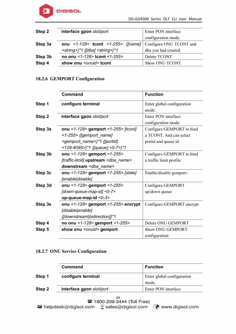
DG-GO4300 Series OLT CLI User Manual
69
Step 2 interface gpon slot/port Enter PON interface configuration mode.
Step 3a onu <1-128> tcont <1-255> {[name] <string>}*1 {[dba] <string>}*1
Configure ONU TCONT and dba you had created.
Step 3b no onu <1-128> tcont <1-255> Delete TCONT Step 4 show onu <onuid> tcont Show ONU TCONT
18.2.6 GEMPORT Configuration
Command Function
Step 1 configure terminal Enter global configuration mode.
Step 2 interface gpon slot/port Enter PON interface configuration mode.
Step 3a onu <1-128> gemport <1-255> [tcont] <1-255> {[gemport_name] <gemport_name>}*1 {[portid] <129-4095>}*1 {[queue] <0-7>}*1
Configure GEMPORT to bind a TCONT. And can select portid and queue id
Step 3b onu <1-128> gemport <1-255> [traffic-limit] upstream <dba_name> downstream <dba_name>
Configure GEMPORT to bind a traffic limit profile
Step 3c onu <1-128> gemport <1-255> [state] [enable|disable]
Enable/disable gemport。
Step 3d onu <1-128> gemport <1-255> [down-queue-map-id] <0-7> up-queue-map-id <0-3>
Configure GEMPORT up/down queue
Step 3e onu <1-128> gemport <1-255> encrypt [disable|enable] {[downstream|bidirection]}*1
Configure GEMPORT encrypt
Step 4 no onu <1-128> gemport <1-255> Delete ONU GEMPORT Step 5 show onu <onuid> gemport Show ONU GEMPORT
configuration
18.2.7 ONU Service Configuration
Command Function
Step 1 configure terminal Enter global configuration mode.
Step 2 interface gpon slot/port Enter PON interface

DG-GO4300 Series OLT CLI User Manual
70
configuration mode. Step 3a onu <1-128> service <service_name>
gemport <1-255> [vlan] <vlan_list> {[iphost] <1-255>}*1 {[ethuni] lan <1-32>}*1 {[cos] <cos_list>}*1
Configure ONU service with vlan
Step 3b onu <1-128> service <service_name> gemport <1-255> [untag] {[ethuni] lan <1-32>}*1 {[iphost] <1-255>}*1
Configure ONU service without vlan
Step 4 no onu <1-128> service <service_name>
Delete ONU service
18.2.8 Configure the service-port
Configure the service-port .
Command Function
Step 1 configure terminal Enter global configuration mode.
Step 2 interface gpon slot/port Enter PON interface configuration mode.
Step 3a onu <1-128> service-port <1-128> gemport <1-128> uservlan <1-4094> {[to] <1-4094>}*1 transparent
Configure the vlan transparent mode
Step 3b onu <1-128> service-port <1-128> gemport <1-128> uservlan <1-4094> [user_priority] <0-7> [vlan] <1-4094> {[new_cos] <0-7>}*1
Configure the vlan translate mode
Step 3c onu <1-128> service-port <1-128> gemport <1-128> uservlan <1-4094> [vlan] <1-4094> {[new_cos] <0-7>}*1 {[svlan] <1-4094>}*1 {[new_scos] <0-7>}*1
Configure the vlan translate mode and QinQ
Step 3d onu <1-128> service-port <1-128> gemport <1-128> uservlan <1-4094> [user_etype] [pppoe|ipoe] [vlan] <1-4094> {[new_cos] <0-7>}*1 {[svlan] <1-4094>}*1 {[new_scos] <0-7>}*1
Configure the vlan translate mode and QinQ.can select the type of packets
Step 3e onu <1-128> service-port <1-128> gemport <1-128> uservlan <1-4094> [user_etype] [user_define] <eth_type> [vlan] <1-4094> {[new_cos] <0-7>}*1 {[svlan] <1-4094>}*1 {[new_scos] <0-7>}*1
Configure the vlan translate mode and QinQ.can select the type that user define.
Step 3f onu <1-128> service-port <1-128> gemport <1-128> uservlan untag [user_etype] [user_define] <eth_type> [vlan]
Configure the vlan untagged mode, can configure QinQ and type that user define.

DG-GO4300 Series OLT CLI User Manual
71
<1-4094> {[new_cos] <0-7>}*1 {[svlan] <1-4094>}*1 {[new_scos] <0-7>}*1
Step 3g onu <1-128> service-port <1-128> gemport <1-128> uservlan untag [vlan] <1-4094> {[new_cos] <0-7>}*1 {[svlan] <1-4094>}*1 {[new_scos] <0-7>}*1
Configure the vlan untagged mode,can configure QinQ
Step 4 onu <1-128> service-port <1-128> admin-status [enable|disable]
Enable/disable service-port
Step 5 onu <1-128> service-port <1-128> description <desc>
Configure the service-port description
Step 6 no onu <1-128> service-port <1-128> Delete the service-port
18.2.9 ONU UNI Configuration
Inclue LAN, VEIP, IPHOST
Command Function
Step 1 configure terminal Enter global configuration mode.
Step 2 interface gpon slot/port Enter PON interface configuration mode.
Step 3a onu <1-128> portvlan [eth|wifi|veip] <1-32> [mode] [transparent]
Configure the UNI mode is transparent
Step 3b onu <1-128> portvlan [eth|wifi|veip] <1-32> [mode] [trunk]
Configure the UNI mode is trunk
Step 3c onu <1-128> portvlan [eth|wifi|veip] <1-32> [mode] [tag] vlan <1-4094> {pri <0-7>}*1
Configure the UNI mode is access and bind a vlan
Step 3d onu <1-128> portvlan [eth|wifi|veip] <1-32> [mode] [hybrid] def_vlan <1-4094> {def_pri <0-7>}*1
Configure the UNI mode is hybrid and bind a vlan
Step 3e onu <1-128> portvlan [eth|wifi|veip] <1-32> [vlan] <vlan_list>
Configure the list of UNI vlan
Step 3f onu <1-128> portvlan [eth|wifi|veip] <1-32> [translate] [vlan] <1-4094> [cvlan] <1-4094> {[cvlan_pri] <0-7>}*1 [svlan] <1-4094> {[svlan_pri] <0-7>}*1
Configure the UNI mode is translate
18.2.10 ONU FEC Configuration
Enable/disable ONU FEC
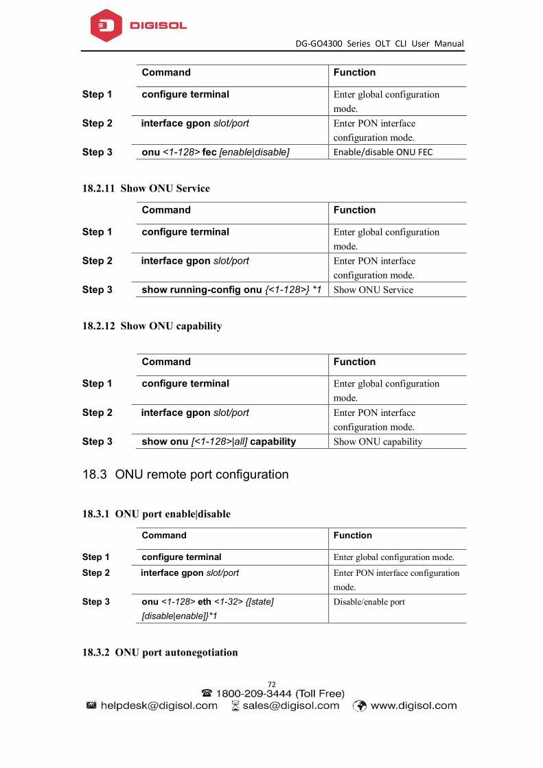
DG-GO4300 Series OLT CLI User Manual
72
Command Function
Step 1 configure terminal Enter global configuration mode.
Step 2 interface gpon slot/port Enter PON interface configuration mode.
Step 3 onu <1-128> fec [enable|disable] Enable/disable ONU FEC
18.2.11 Show ONU Service
Command Function
Step 1 configure terminal Enter global configuration mode.
Step 2 interface gpon slot/port Enter PON interface configuration mode.
Step 3 show running-config onu {<1-128>} *1 Show ONU Service
18.2.12 Show ONU capability
Command Function
Step 1 configure terminal Enter global configuration mode.
Step 2 interface gpon slot/port Enter PON interface configuration mode.
Step 3 show onu [<1-128>|all] capability Show ONU capability
18.3 ONU remote port configuration
18.3.1 ONU port enable|disable
Command Function
Step 1 configure terminal Enter global configuration mode.
Step 2 interface gpon slot/port Enter PON interface configuration mode.
Step 3 onu <1-128> eth <1-32> {[state] [disable|enable]}*1
Disable/enable port
18.3.2 ONU port autonegotiation
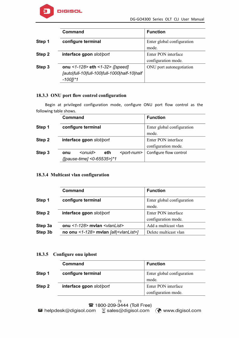
DG-GO4300 Series OLT CLI User Manual
73
Command Function
Step 1 configure terminal Enter global configuration mode.
Step 2 interface gpon slot/port Enter PON interface configuration mode.
Step 3 onu <1-128> eth <1-32> {[speed] [auto|full-10|full-100|full-1000|half-10|half-100]}*1
ONU port autonegotiation
18.3.3 ONU port flow control configuration
Begin at privileged configuration mode, configure ONU port flow control as the following table shows.
Command Function
Step 1 configure terminal Enter global configuration mode.
Step 2 interface gpon slot/port Enter PON interface configuration mode.
Step 3 onu <onuid> eth <port-num> {[pause-time] <0-65535>}*1
Configure flow control
18.3.4 Multicast vlan configuration
Command Function
Step 1 configure terminal Enter global configuration mode.
Step 2 interface gpon slot/port Enter PON interface configuration mode.
Step 3a onu <1-128> mvlan <vlanList> Add a multicast vlan Step 3b no onu <1-128> mvlan [all|<vlanList>] Delete multicast vlan
18.3.5 Configure onu iphost
Command Function
Step 1 configure terminal Enter global configuration mode.
Step 2 interface gpon slot/port Enter PON interface configuration mode.
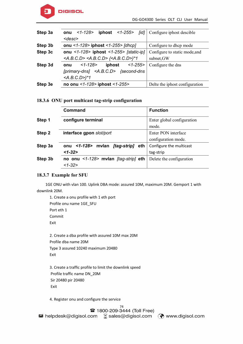
DG-GO4300 Series OLT CLI User Manual
74
Step 3a onu <1-128> iphost <1-255> [id] <desc>
Configure iphost descible
Step 3b onu <1-128> iphost <1-255> [dhcp] Configure to dhcp mode Step 3c onu <1-128> iphost <1-255> [static-ip]
<A.B.C.D> <A.B.C.D> {<A.B.C.D>}*1 Configure to static mode,and subnet,GW
Step 3d onu <1-128> iphost <1-255> [primary-dns] <A.B.C.D> {second-dns <A.B.C.D>}*1
Configure the dns
Step 3e no onu <1-128> iphost <1-255> Delte the iphost configuration
18.3.6 ONU port multicast tag-strip configuration
Command Function
Step 1 configure terminal Enter global configuration mode.
Step 2 interface gpon slot/port Enter PON interface configuration mode.
Step 3a onu <1-128> mvlan [tag-strip] eth <1-32>
Configure the multicast tag-strip
Step 3b no onu <1-128> mvlan [tag-strip] eth <1-32>
Delete the configuration
18.3.7 Example for SFU
1GE ONU with vlan 100. Uplink DBA mode: assured 10M, maximum 20M. Gemport 1 with downlink 20M.
1. Create a onu profile with 1 eth port Profile onu name 1GE_SFU Port eth 1 Commit Exit 2. Create a dba profile with assured 10M max 20M Profile dba name 20M Type 3 assured 10240 maximum 20480 Exit 3. Create a traffic profile to limit the downlink speed
Profile traffic name DN_20M Sir 20480 pir 20480 Exit
4. Register onu and configure the service

DG-GO4300 Series OLT CLI User Manual
75
Interface gpon 0/1 Show onu auto-find Onu add 1 profile 1GE_SFU sn GPON00000031 Onu 1 tcont 1 dba 20M Onu 1 gemport 1 tcont 1 Onu 1 gemport 1 traffic-limit upstream default downstream DN_20M Onu 1 service 1 gemport 1 vlan 100 Onu 1 service-port 1 gemport 1 user-vlan 100 vlan 100 Onu 1 portvlan eth 1 mode tag vlan 100
5. Create vlan 100 Vlan 100 Exit
6. Bind the vlan to uplink port
Interface gigabitethernet 0/10 Switchport hybrid pvid vlan 100
18.3.8 Example for HGU
4FE ONU with vlan 41 and vlan 46. Uplink DBA mode: assured 10M, maximum 20M. Gemport 1 with downlink 20M. vlan 46 is for tr069 , DBA mode: fixed 2M
1. Create a onu profile with 1 veip port Profile onu name HGU Port veip 1 Commit Exit 2. Create a dba profile Profile dba name 20M Type 3 assured 10240 maximum 20480 Exit Profile dba name 2M Type 1 fixed 2048 Exit 3. Create a traffic profile to limit the downlink speed
Profile traffic name DN_20M Sir 20480 pir 20480 Exit
4. register onu and configure the service Interface gpon 0/1

DG-GO4300 Series OLT CLI User Manual
76
Show onu auto-find Onu add 1 profile HGU sn GPON000000AB Onu 1 tcont 1 dba 20M Onu 1 tcont 2 dba 2M Onu 1 gemport 1 tcont 1 Onu 1 gemport 1 traffic-limit upstream default downstream DN_20M Onu 1 service HSI gemport 1 vlan 41 Onu 1 service-port 1 gemport 1 user-vlan 41 vlan 41 Onu 1 gemport 2 tcont 2 Onu 1 service TR69 gemport 2 vlan 46 Onu 1 service-port 2 gemport 2 user-vlan 46 vlan 46
Onu 1 portvlan veip 1 mode transparent 5. Create vlan 41 and 46, bind to uplink port Vlan 41 Exit Vlan 46 Exit
Interface gigabitethernet 0/10 Switchport mode trunk Switchport trunk vlan 41 Switchport trunk vlan 46
6. Login to onu webinterface, create two WAN connection,one is internet with vlan41;
another one is tr069 with vlan46
18.4 Rogue-onu configuration
We called this rogue ONT which does not follow the assigned timestamp to send up the optical signal. Rogue ONT mainly divided into the following two types: 1) The long Lighting rogue ont: ONT is lighting (glowing at any moment). 2) Luminous rogue ont: Lighting in OLT non allocation of the timestamp, may be light in advance, or delay to turn off and so on.
18.4.1 Configure the rogue-onu-detect
Command Function
Step 1 configure terminal Enter global configuration mode.

DG-GO4300 Series OLT CLI User Manual
77
Step 2 rogue-onu-detect [enable|disable] locate [enable|disable] auto-shutdown [enable|disable]
Enable/disable detect/locate/auto-shudown function
Step 3 show rogue-onu-detect config Show the configuration Step 4 show rogue-onu-detect info pon <1-8> Show the result
18.4.2 Configure the rogue-onu status
Command Function
Step 1 configure terminal Enter global configuration mode.
Step 2 rogue-onu-state pon <1-8> onu <1-128> [on|off|shutdown] duration [forever|<1-255>]
Configure the rogue-onu online/offline/shutdown and duration time
Step 3 show rogue-onu-detect config Show the configuration

DG-GO4300 Series OLT CLI User Manual
78
19. ONU template management
19.1 Summary of the ONU template
Template under “config” node, the operation steps are as follows: 1.Create a template profile [onu|dba|traffic|line|srv|voip|alarm] {id <1-32767>}*1 {name <string>}*1 2.Through profile_id into the corresponding template node profile [onu|dba|traffic|line|srv|voip|alarm] {id <1-32767>}*1 {name <string>}*1 3.Modify the template parameters modify … 4.Exit template node exit 5.Binding template to an onu equipment Interface gpon slot/port onu add 1 profile <string> onu <onuid> profile [line|srv] <string> 6.Query onu equipment binding template Interface gpon slot/port show profile [onu|dba|traffic|line|srv|voip|alarm] {id <1-32767>}*1 {name <string>}*1 7. query template configuration information Show profile [onu|dba|traffic|line|srv|voip|alarm] {id <1-32767>}*1 {name <string>}*1
used-info
19.2 ONU profile configuration
The Onu template is used for onu authorization, and each ONU must specify only one ONU template when authorizated. The ONU template specifies the capability of this ONU.
Command Function
Step 1 configure terminal Enter global configuration mode.
Step 2 profile onu {id <1-32767>}*1 {name <string>}*1
Create or enter the onu profile you had created before.
Step 3a tcont-num <1-255> gemport-num <1-255> Configure the onu support max tcont and gemport.
Step 3b switch-num <1-255> flow-num <1-255> Configure the onu support max switch and flow
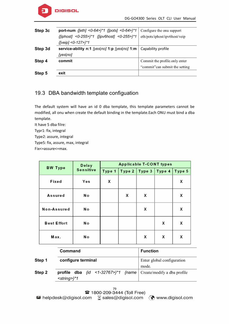
DG-GO4300 Series OLT CLI User Manual
79
Step 3c port-num {[eth] <0-64>}*1 {[pots] <0-64>}*1 {[iphost] <0-255>}*1 {[ipv6host] <0-255>}*1 {[veip] <0-127>}*1
Configure the onu support eth/pots/iphost/ipv6host/veip
Step 3d service-ability n:1 [yes|no] 1:p [yes|no] 1:m [yes|no]
Capability profile
Step 4 commit Commit the profile.only enter “commit”can submit the setting
Step 5 exit
19.3 DBA bandwidth template configuation
The default system will have an id 0 dba template, this template parameters cannot be modified, all onu when create the default binding in the template.Each ONU must bind a dba template. It have 5 dba filre: Typr1: fix, integral Type2: assure, integral Type5: fix, assure, max, integral Fix<=assure<=max.
Command Function
Step 1 configure terminal Enter global configuration mode.
Step 2 profile dba {id <1-32767>}*1 {name <string>}*1
Create/modify a dba profile

DG-GO4300 Series OLT CLI User Manual
80
Step 3a type [1] fixed <64-2488320> Configure type 1 with fixed Step 3b type [2] assured <64-2488320> Configure type 2 with assured Step 3c type [3] assured <64-2488320>
maximum <64-2488320> Configure type 3 with assured and maximum
Step 3d type [4] maximum <64-2488320> {[priority] <1-4>}*1 {[weight] <1-1000>}*1
Configure type 4 with maximum
Step 3e type [5] fixed <64-2488320> assured <64-2488320> maximum <64-2488320> {[priority] <1-4>}*1 {[weight] <1-1000>}*1
Configure type 5 with fixed, assured, maximum.
19.4 Traffic template configuation
The default system will have an id 0 traffic template, this template parameters cannot be modified, all GEMPORT when create the default binding in the template.Each GEMPORT must bind a traffic template.。 parameter Detail Range Sir sustained information rate 0-10000000kbps Pir Peak information rate 64-10000000kbps Cbs Committed Burst Size 0-1023kbytes pbs Peak Burst Size 0-1023kbytes
Command Function
Step 1 configure terminal Enter global configuration mode.
Step 2 profile traffic {id <1-32767>}*1 {name <string>}*1
Creat/modify a traffic profile
Step 3 sir <0-10000000> pir <64-10000000> {cbs <0-1023> pbs <0-1023>}*1
Configure the sir and pri, cbs and pbs is selectable.
Step 4 Exit Exit
19.5 Line template configuation
The default system will have an id 0 LINE template, this template parameters cannot be modified,
Command Function
Step 1 configure terminal Enter global configuration mode.
Step 2 profile line {id <1-32767>}*1 {name Create/modify a line profile

DG-GO4300 Series OLT CLI User Manual
81
<string>}*1 Step 3a tcont <1-255> {[name] <string>}*1 {[dba]
<string>}*1 Bind a tcont profile
Step 4a gemport <1-255> [tcont] <1-255> {[gemport_name] <gemport_name>}*1 {[portid] <129-4095>}*1 {[queue] <0-7>}*1
Bind a gemport profile
Step 4b gemport <1-255> [encrypt] [enable|disable]
Enable/disable the gemport encrypt.by default, is enable
Step 4c gemport <1-255> [state] [enable|disable] Enable/disable the gemport state
Step 4d gemport <1-255> [traffic-limit] upstream <dba_name> downstream <dba_name>
Bind a up/downstream limit to gemport
Step 5a service <service_name> gemport <1-255> [vlan] <vlan_list> {[iphost] <1-255>}*1 {[ethuni] lan <1-32>}*1 {[cos] <cos_list>}*1
Bind a gemport which with vlan to service
Step 5b service <service_name> gemport <1-255> [untag] {[ethuni] lan <1-32>}*1 {[iphost] <1-255>}*1
Bind a gemport without vlan to service
Step 5c mvlan <vlanlist> Create the multicast vlan Step 6a service-port <1-128> gemport <1-128>
uservlan <1-4094> {[to] <1-4094>}*1 transparent
Configure the vlan mode to transparent
Step 6b service-port <1-128> gemport <1-128> uservlan <1-4094> [user_priority] <0-7> [vlan] <1-4094> {[new_cos] <0-7>}*1
Configure the vlan mode to translate
Step 6c service-port <1-128> gemport <1-128> uservlan <1-4094> [vlan] <1-4094> {[new_cos] <0-7>}*1 {[svlan] <1-4094>}*1 {[new_scos] <0-7>}*1
Configure the vlan mode to translate,QinQ
Step 6d service-port <1-128> gemport <1-128> uservlan <1-4094> [user_etype] [pppoe|ipoe] [vlan] <1-4094> {[new_cos] <0-7>}*1 {[svlan] <1-4094>}*1 {[new_scos] <0-7>}*1
Configure the vlan mode to translate,QinQ,can select the type of data
Step 6e service-port <1-128> gemport <1-128> uservlan <1-4094> [user_etype] [user_define] <eth_type> [vlan] <1-4094> {[new_cos] <0-7>}*1 {[svlan] <1-4094>}*1 {[new_scos] <0-7>}*1
Configure the vlan mode to translate,QinQ,can select the type that user define
Step 6f service-port <1-128> gemport <1-128> uservlan untag [user_etype] [user_define] <eth_type> [vlan] <1-4094> {[new_cos]
Configure the vlan mode to untag,QinQ,can select the type that user define
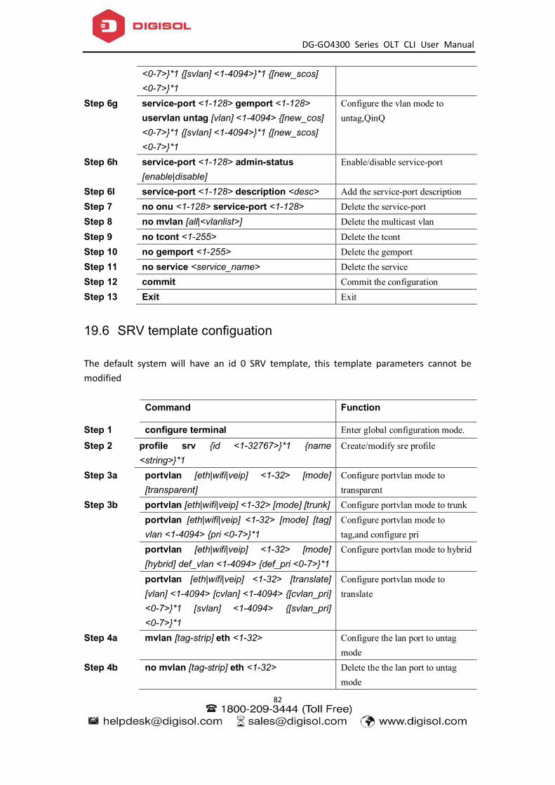
DG-GO4300 Series OLT CLI User Manual
82
<0-7>}*1 {[svlan] <1-4094>}*1 {[new_scos] <0-7>}*1
Step 6g service-port <1-128> gemport <1-128> uservlan untag [vlan] <1-4094> {[new_cos] <0-7>}*1 {[svlan] <1-4094>}*1 {[new_scos] <0-7>}*1
Configure the vlan mode to untag,QinQ
Step 6h service-port <1-128> admin-status [enable|disable]
Enable/disable service-port
Step 6I service-port <1-128> description <desc> Add the service-port description Step 7 no onu <1-128> service-port <1-128> Delete the service-port Step 8 no mvlan [all|<vlanlist>] Delete the multicast vlan Step 9 no tcont <1-255> Delete the tcont Step 10 no gemport <1-255> Delete the gemport Step 11 no service <service_name> Delete the service Step 12 commit Commit the configuration Step 13 Exit Exit
19.6 SRV template configuation
The default system will have an id 0 SRV template, this template parameters cannot be modified
Command Function
Step 1 configure terminal Enter global configuration mode.
Step 2 profile srv {id <1-32767>}*1 {name <string>}*1
Create/modify sre profile
Step 3a portvlan [eth|wifi|veip] <1-32> [mode] [transparent]
Configure portvlan mode to transparent
Step 3b portvlan [eth|wifi|veip] <1-32> [mode] [trunk] Configure portvlan mode to trunk portvlan [eth|wifi|veip] <1-32> [mode] [tag]
vlan <1-4094> {pri <0-7>}*1 Configure portvlan mode to tag,and configure pri
portvlan [eth|wifi|veip] <1-32> [mode] [hybrid] def_vlan <1-4094> {def_pri <0-7>}*1
Configure portvlan mode to hybrid
portvlan [eth|wifi|veip] <1-32> [translate] [vlan] <1-4094> [cvlan] <1-4094> {[cvlan_pri] <0-7>}*1 [svlan] <1-4094> {[svlan_pri] <0-7>}*1
Configure portvlan mode to translate
Step 4a mvlan [tag-strip] eth <1-32> Configure the lan port to untag mode
Step 4b no mvlan [tag-strip] eth <1-32> Delete the the lan port to untag mode

DG-GO4300 Series OLT CLI User Manual
83
Step 5a iphost <1-255> [id] <desc> Configure the iphost description Step 5b iphost <1-255> [dhcp] Configure the iphost to dhcp mode Step 5c iphost <1-255> [static-ip] <A.B.C.D>
<A.B.C.D> {<A.B.C.D>}*1 Configure the iphost to static mode.
Step 5d iphost <1-255> [primary-dns] <A.B.C.D> {second-dns <A.B.C.D>}*1
Configure the DNS
Step 5e no iphost <1-255> Delete the iphost setting Step 6 Commit Commit the configuration Step 7 Exit Exit
19.7 Alarm threshold template configuration
Alarm threshold only can be configured by template. Begin at privileged configuration mode, configure alarm threshold template as the following table shows.
Command Function
Step 1 configure terminal Enter global configuration mode.
Step 2 profile alarm {id <1-32767>}*1 {name <string>}*1
Create or enter a profile
Step 3a sf-sd-threshold sf <3-8> sd <4-10> Configure the range of sf and sd Step 3b rx-optical low <-27~-8> upper <-27~-8> Configure the range of rx-optical Step 3c Tx-optical low <0-5> upper <0-5> Configure the range of tx-optical Step 4 Commit Commit the configuration Step 5 Exit Exit
19.8 Show/Delete the profile configuration
Command Function
Step 1 configure terminal Enter global configuration mode.
Step 2 no profile {dba|srv|voip|alarm} id <1-32767>
Delete profile
Step 3a show profile {dba|srv|voip|alarm} all|id <0-65535> }
Show profile
Step 3b show profile {dba|srv|voip|alarm} id <0-65535> bind
Show the onu which binding profile

DG-GO4300 Series OLT CLI User Manual
84
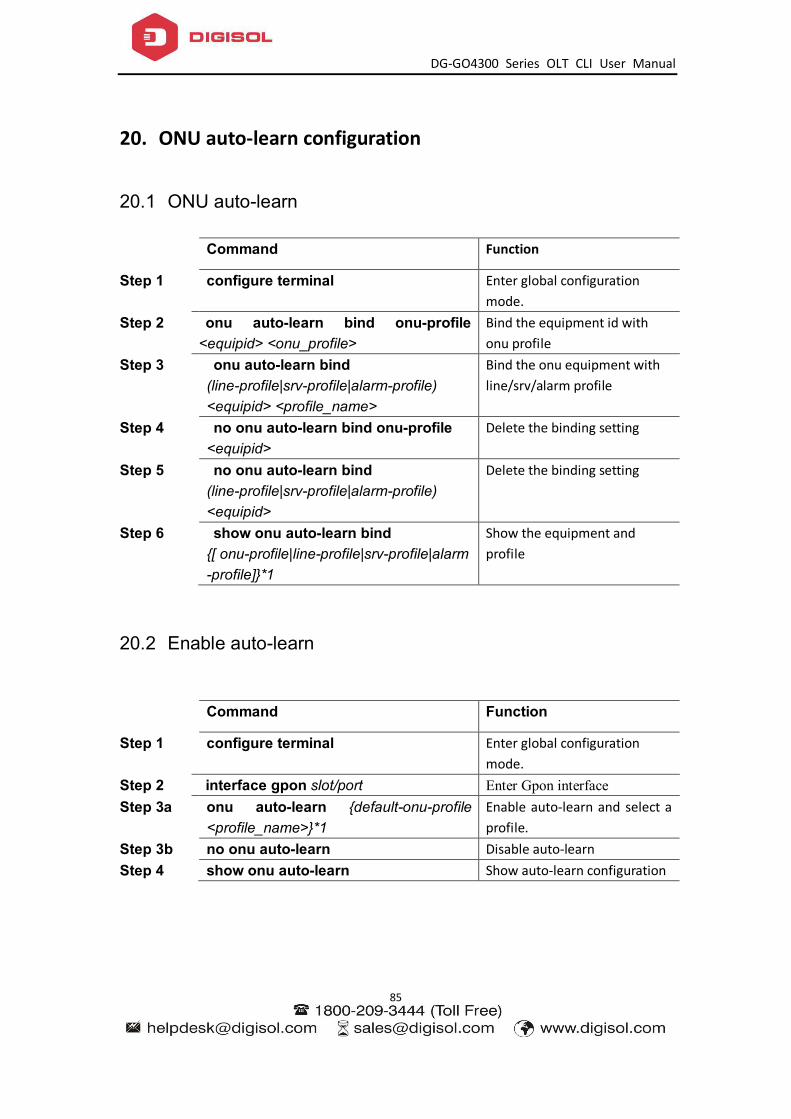
DG-GO4300 Series OLT CLI User Manual
85
20. ONU auto-learn configuration
20.1 ONU auto-learn
Command Function
Step 1 configure terminal Enter global configuration mode.
Step 2 onu auto-learn bind onu-profile <equipid> <onu_profile>
Bind the equipment id with onu profile
Step 3 onu auto-learn bind (line-profile|srv-profile|alarm-profile) <equipid> <profile_name>
Bind the onu equipment with line/srv/alarm profile
Step 4 no onu auto-learn bind onu-profile <equipid>
Delete the binding setting
Step 5 no onu auto-learn bind (line-profile|srv-profile|alarm-profile) <equipid>
Delete the binding setting
Step 6 show onu auto-learn bind {[ onu-profile|line-profile|srv-profile|alarm-profile]}*1
Show the equipment and profile
20.2 Enable auto-learn
Command Function
Step 1 configure terminal Enter global configuration mode.
Step 2 interface gpon slot/port Enter Gpon interface Step 3a onu auto-learn {default-onu-profile
<profile_name>}*1 Enable auto-learn and select a profile.
Step 3b no onu auto-learn Disable auto-learn Step 4 show onu auto-learn Show auto-learn configuration

DG-GO4300 Series OLT CLI User Manual
86
21. System Management
21.1 Configuration file management
21.1.1 Save configurations
After modified the configurations, you should same them so that these configurations can take effect next time it restarts. Use the following commands to save configurations.
Command Function
Step 1 configure terminal Enter global configuration mode.
Step 2 write Save configurations.
21.1.2 Erase configurations
If you need to reset to factory default, you can use the following commands to erase all configurations. After erased, the device will reboot automatically.
Command Function
Step 1 configure terminal Enter global configuration mode.
Step 2 erase startup-config Erase all configurations.
21.1.3 Show startup configurations
Use the following command to display the configurations you have saved.
Command Function
Step 1 configure terminal Enter global configuration mode.
Step 2 show startup-config Show configuration
21.1.4 Show running configurations
Use the following commands to display running configurations. These running configurations may not be saved in flash.
Command Function
Step 1 configure terminal Enter global configuration mode.
Step 2 show running-config Show running configurations.

DG-GO4300 Series OLT CLI User Manual
87
21.1.5 Upload/download configuration file
Use the following commands to upload configuration file to PC and download configuration file to device.
Command Function
Step 1 configure terminal Enter global configuration mode.
Step 2 debug mode Enter debug node Step 3a upload tftp configuration <filename>
<A.B.C.D> filename is Upgrade file A.B.C.D is TFTP server IP
Step 3b download tftp configuration <filename> <A.B.C.D>
filename is Upgrade file A.B.C.D is TFTP server IP
21.2 Check the system information
21.2.1 Check system running information
Use the following commands to view system information. Command Function show sys arp Show ARP table
show sys cpu Show CPU information
show sys cpu-usage Show CPU usage rate
show sys mem Show system memory
show sys ps Show system process
show top Show CPU utilization
show task Showthread name
21.2.2 Check version information
Use the following commands to check version information which includes hardware version, software version, software created time and so on. Command Function Step 1 configure terminal Enter global configuration
mode. Step 2 show version Show version information.
21.2.3 Check system running time
Use the following command to show system running time after turned power on. Command Function

DG-GO4300 Series OLT CLI User Manual
88
Step 1 configure terminal Enter global configuration mode.
Step 2 show sys running-time Show system running time.
21.3 System basic configurations
21.3.1 Configure system name
Use the following command to modify system name. This modification will take effect immediately. You will see it in command prompt prefix. Begin at privileged configuration mode,configure system name as the following table shows. Command Function Step 1 configure terminal Enter global configuration
mode. Step 2 hostname <name> Configure system name. It
must start with alphabet. Step 3 hostname default Restore default
21.3.2 Configure terminal display attribute
This command is used to configure display line number when access by console port or telnet. Begin at privileged configuration mode, configure terminal display attribure as the followingtable shows.
Command Function
Step 1 configure terminal Enter global configuration mode.
Step 2 terminal length value Configure display line number. Value range is 0-512.
21.3.3 Configure terminal time-out value
Use the following commands to configure terminal time-out value. Default value is 10 minutes. Command Function Step 1 configure terminal Enter global configuration
mode. Step 2 line vty Enter line node Step 3a exec-timeout <min> [<second>] Set the command-line timeout Step 3b no exec-timeout Set the command-line timeout
to default Step 4 show exec-timeout Show the command-line
timeout

DG-GO4300 Series OLT CLI User Manual
89
21.4 System basic operations
21.4.1 Upgrade system
Use the following command to upgrade the equipment.
Command Function
Step 1 configure terminal Enter global configuration mode.
Step 2b download tftp image <filename> <A.B.C.D>
Update firmware with header.
21.4.2 Network connectivity test
Use ping command to check network connectivity. Command Function Step 1 configure terminal Enter global configuration
mode. Step 2 ping [-s <packetsize>] <A.B.C.D> Packetsize is test packet length,
unit is byte.
21.4.3 Reboot system
Use the following command to reboot system. Command Function Step 1 configure terminal Enter global configuration
mode. Step 2 reboot Reboot system.
21.4.4 Telnet
You can telent to system via outband or inband management IP. The default outband management IP is 192.168.8.100. Command Function telnet 192.168.200 Telnet to application layer of
system. Login name and passwork both are admin.
telnet 192.168.200 2223 Telnet to kernel of system. Login name is default.
GPON-OLT(config)#switch Telnet to kernel of system. Login name is default.
21.4.5 Configure RTC system time
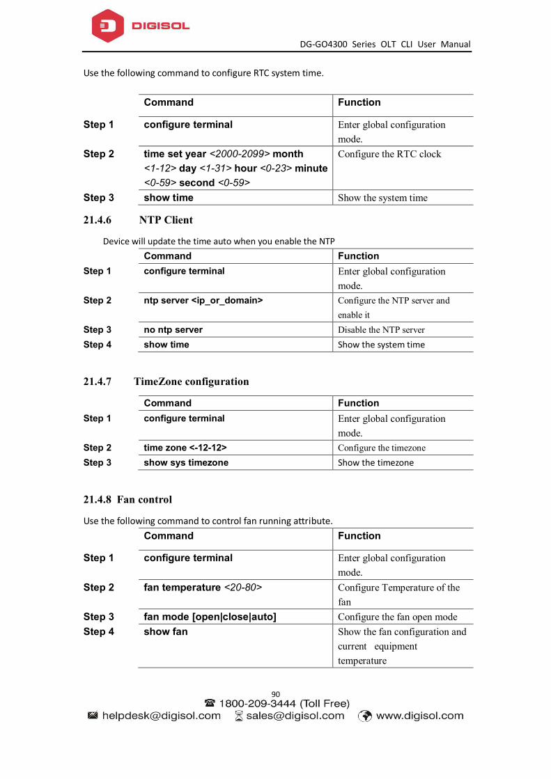
DG-GO4300 Series OLT CLI User Manual
90
Use the following command to configure RTC system time.
Command Function
Step 1 configure terminal Enter global configuration mode.
Step 2 time set year <2000-2099> month <1-12> day <1-31> hour <0-23> minute <0-59> second <0-59>
Configure the RTC clock
Step 3 show time Show the system time
21.4.6 NTP Client
Device will update the time auto when you enable the NTP Command Function Step 1 configure terminal Enter global configuration
mode. Step 2 ntp server <ip_or_domain> Configure the NTP server and
enable it Step 3 no ntp server Disable the NTP server Step 4 show time Show the system time
21.4.7 TimeZone configuration
Command Function Step 1 configure terminal Enter global configuration
mode. Step 2 time zone <-12-12> Configure the timezone Step 3 show sys timezone Show the timezone
21.4.8 Fan control
Use the following command to control fan running attribute.
Command Function
Step 1 configure terminal Enter global configuration mode.
Step 2 fan temperature <20-80> Configure Temperature of the fan
Step 3 fan mode [open|close|auto] Configure the fan open mode Step 4 show fan Show the fan configuration and
current equipment temperature

DG-GO4300 Series OLT CLI User Manual
91
21.5 Debug information
21.5.1 Enable/disable CPU debug information
Use the following commands to enable or disable CPU debug information. Command Function Step 1 configure terminal Enter global configuration mode. Step 2 debug mode Enter debug node. Step 3 system debug {rx|tx} {on|off} On|off : enable or disable CPU
debug. Rx: CPU receives packets. Tx: CPU transmits packets.
21.5.2 Enable/disable each function module debug information
Use the following commands to enable or disable function module debug information. Command Function Step 1 configure terminal Enter global configuration mode. Step 2 debug mode Enter debug node. Step 3 system debug {acl|timer|port|mac|vlan|vt|
igmp|cfp|qos} {on|off} On|off : enable or disable function module debug information.
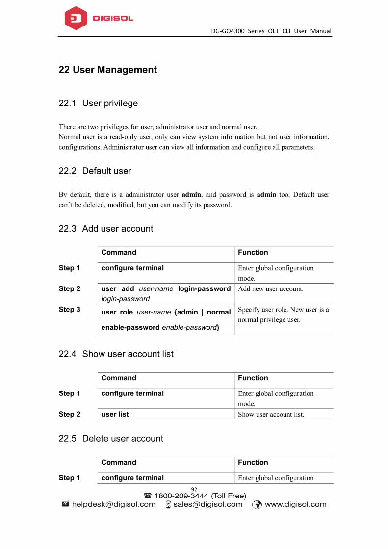
DG-GO4300 Series OLT CLI User Manual
92
22 User Management
22.1 User privilege
There are two privileges for user, administrator user and normal user. Normal user is a read-only user, only can view system information but not user information, configurations. Administrator user can view all information and configure all parameters.
22.2 Default user
By default, there is a administrator user admin, and password is admin too. Default user can’t be deleted, modified, but you can modify its password.
22.3 Add user account
Command Function
Step 1 configure terminal Enter global configuration mode.
Step 2 user add user-name login-password login-password
Add new user account.
Step 3 user role user-name {admin | normal
enable-password enable-password}
Specify user role. New user is a normal privilege user.
22.4 Show user account list
Command Function
Step 1 configure terminal Enter global configuration mode.
Step 2 user list Show user account list.
22.5 Delete user account
Command Function
Step 1 configure terminal Enter global configuration

DG-GO4300 Series OLT CLI User Manual
93
mode. Step 2 user delete username Delete user account.
22.6 Modify password
Every user can modify its own password while administrator user can modify other users’ password. Modify password as the following table shows.
Command Function
Step 1 configure terminal Enter global configuration mode.
Step 2 user login-password user-name <CR> Input new login password for user abc please. New Password: Confirm Password:
Configure user’s login password.
Step 3 user enable-password user-name <CR> Input new enable password for user abc please. New Password: Confirm Password:
Configure user’s configuration mode password.

DG-GO4300 Series OLT CLI User Manual
94
23 SNMP Configuration
23.1 SNMP introduction
SNMP (Simple Network Management Protocol) is an extensive network management protocol at the moment. It is an industrial standard which is adopted and come into use for transmitting management information between two devices. Network administrator can search information, modify information, troubleshoot, diagnose fault, plan capacity and generate resports. SNMP adopts polling mechanism and provides basic functions, especially fits small, fast and low cost conditions. It is based on transport layer protocol UDP. There are two parts of SNMP, NMS (Network Management Station) and agent. NMS is a station that runs client program, and agent is a server program that runs in device. NMS can send GetRequest, GetNextRequest and SetRequest messages to agent. Then agent will execute read or write command and respond to NMS. Agent also sends trap messages to NMS when device is abnormal.
23.2 SNMP version and MIB
In order to mark device’s management variable uniquely, SNMP identifies management object by hierarchical structure name scheme. The set of objects is like a tree, which the node stands for management object, shown as the following picture.
MIB(Management Information Base), a set of device’s variable definition, is used to describe the tree’s hierarchical structure. For the management object B in above picture, we can use a string of numbers {1.2.1.1} to describe it uniquely. This string of numbers is Object Identifier. gpon-olt series OLT support SNMP V1, V2C and V3. Common MIB shows in the following table. MIB attribute MIB content Refer to

DG-GO4300 Series OLT CLI User Manual
95
Public MIB MIB II based on TCP/IP RFC1213 RMON MIB RFC2819 Ethernet MIB RFC2665
Private MIB VLAN MIB
Device management Interface management
23.3 Configure SNMP
23.3.1 Configure community
Begin at privileged configuration mode, configure community as the following table shows.
Command Function
Step 1 config terminal Enter global configuration mode.
Step 2 snmp-server community <word> [ro| rw ]
Configure SNMP community strings;
Step 3 show snmp-server community Show the SNMP community configuration
Step 4 exit From the global configuration mode to return to the privileged user configuration mode
Step 5 write Save the configuration
23.3.2 Configure Trap the target host address
Use the following command to configure or remove the Trap messages of the target host IP address. Begin at privileged configuration mode, Configure Trap the target host address as the following table shows.
Command Function
Step 1 config terminal Enter global configuration mode.
Step 2a snmp-server host <A.B.C.D >{udp-port <1-65535>}*1 {version [1|2c]}*1 {community <WORD>}*1
Configure the Trap the target host address. Configure the community string value
Step 2b no snmp-server host < A.B.C.D > version 1|2c|3 community
Delete trap target host address.
Step 3a snmp-server enable traps snmp Enable SNMP traps function

DG-GO4300 Series OLT CLI User Manual
96
Step 3b no snmp-server enable traps snmp Delete SNMP traps function
Step 4 show snmp-server targetaddress Check the SNMP trap configuration
Step 5 write Save the configuration
23.3.3 Configure Administrator ID and contact method
Begin at privileged configuration mode, Configure administrator ID and contact mwthod as the following table shows.
Command Function
Step 1 config terminal Enter global configuration mode.
Step 2 snmp-server contact <line> Configure contact string value
Step 3 show snmp-server contact Check the SNMP contact configuration.
Step 4 write Save the configuration.
23.3.4 Configure Ethernet switch location information
Begin at privileged configuration mode, Configure Ethernet switch location information as the following table shows.
Command Function
Step 1 config terminal Enter global configuration mode
Step 2 snmp-server location <line> Configure location string value
Step 3 show snmp-server location Check the SNMP location configuration.
Step 4 write Save the configuration.

DG-GO4300 Series OLT CLI User Manual
97
24 Alarm and Event Management
24.1 Alarm and event introduction
If you enable alarm report, it will trigger alarm events when system occured error or did some important operations. The alarm information will be save in a buffer, you can execute some commands such as show syslog to display. All the alarms can be sent to specific servier. Alarms include fault alarm and recovery alarm. Fault alarm will not disappear until the fault is repaired and the alarm is cleared. Events include running envents and secury events, are notifications which generate and inform administrators under a normal condition. The difference between event and alarm is that event generates under a normal condition while alarm generates under an abnormal condition. Command “show alarm-event information” is used to show description, level, type and class of all alarms and events.
24.2 Alarm management
Alarm severity level includes critical, major, minor and warning. Corresponding level in system log are alerts, critical, major and warnings. Alarm type includes device alarm, communication alarm and disposing alarm. Device alarm contains low temperature, high temperature, CPU usage, memory usage, fan, PON, optical power and so on. Communication alarm contains port up/down, loopback, PON deregister, PON register
failed, PON los, ONU deregister, illegal ONU register, ONU authorized failed, ONU MAC conflication, ONU LOID conflication, ONU link los, ONU dying gasp, ONU link fault, ONU link events, ONU extended OAM notification and so on.
Dispoing alarm contains upgrade failed, upload configuration file failed, download configuration file failed and so on.
24.2.1 System alarms
System alarms show the performance and security of system. The following table shows the system alarm list.
System alarm Reason Default
temp-high Device temperature higher than threshold. disable
temp-low Device temperature lower than threshold. disable

DG-GO4300 Series OLT CLI User Manual
98
cpu-usage-high CPU usage higher than threshold. disable
mem-usage-high Memory usage higher than threshold. disable
fan Fan switch. disable
download-file-failed Download file failed enable
upload-file-failed Upload file failed. enable
upgrade-file-failed Upgrade firmware failed. enable
port-updown Port link up and link down. enable
port-loopback Port loopback. disable
Command Function
Step 1 configure terminal Enter global configuration mode.
Step 2a alarm {temp-high|temp-low| cpu-usage-high|mem-usage-high} disable
Disable system alarm report.
Step 2b alarm {temp-high|temp-low| cpu-usage-high| mem-usage-high} enable <alarm-value> <clear-value>
Enable system alarm report and configure system alarm threshold. alarm-value: alarm threshold. clear-value: clear threshold.
Step 2c alarm {fan|port-updown|port-loopback| register-failed|deregister}{enable|disable}
Enable or disable system alarm report.
Step 3 show alarm configuration Show system alarm configurations.
24.2.2 PON alarms
Get rid of the issue caused by PON port or fiber by monitoring PON alarms, ensure PON works well. The following table shows PON alarm list.
PON alarm Reason Default
pon-txpower-high PON port transmitting power higher than threshold.
enable
pon-txpower-low PON port transmitting power lower than enable

DG-GO4300 Series OLT CLI User Manual
99
threshold.
pon-txbias-high PON port bias current higher than threshold. enable
pon-txbias-low PON port bias current lower than threshold. enable
pon-vcc-high PON port voltage higher than threshold. enable
pon-vcc-low PON port voltage lower than threshold. enable
pon-temp-high PON port temperature higher than threshold. enable
pon-temp-low PON port temperature lower than threshold. enable
pon-los Fiber unconnected or link fault. enable
deregister PON deregister. disable
register-failed PON register failed. enable
Configure global PON alarm as the following table shows. Command Function Step 1 configure terminal Enter global configuration
mode. Step 2a alarm
{pon-register-failed|pon-deregister} {enable|disable}
Enable or disable PON alarm report.
Step 2a alarm {pon-txpower-high| pon-txpower-low|pon-txbias-high| pon-txbias-low|pon-vcc-high| pon-vcc-low|pon-temp-high| pon-temp-low| pon-los} {enable|disable}
Enable or disable PON port alarm report.
Step 3 show alarm configuration Show alarm configurations.
Configure PON port alarm as the following table shows. Before this, you must enable global PON alarm. By default, global PON alarm is enabled, the alarms will be record in system log.
Command Function Step 1 configure terminal Enter global configuration
mode. Step 2 interface gpon slot/port Enter PON interface
configuration mode. Step 3a alarm pon optical {tx_power_high|
tx_power_low|tx_bias_high|tx_bias_low| vcc_high |vcc_low |
Disable PON port alarm report.

DG-GO4300 Series OLT CLI User Manual
100
temp_high|temp_low} disable Step 3b alarm pon optica {tx_power_high|
tx_power_low |tx_bias_high |tx_bias_low| vcc_high |vcc_low | temp_high|temp_low} enable <alarm-value> <clear-value>
Enable PON port alarm report and configure alarm parameters. alarm-value: alarm threshold. clear-value: clear threshold.
Step 4 show alarm pon optical configuration Show PON port alarm configurations.
ONU alarms ONU alarms also can help administrator to get rid of some ONU fault. The following table shows ONU alarm list.
ONU alarm Reason Default
onu-deregister ONU deregister enable
onu-link-lost ONU fiber unconnected or link fault. disable
onu-illegal-register Illegal ONU register. enable
onu-auth-failed ONU LOID authorized failed in auto authorization mode or failed caused by packets loss.
enable
onu-mac-conflict Current PON port exist MAC conflict with authorized ONU in the system.
enable
onu-loid-conflict Current PON port exist LOID conflict with authorized ONU in the system.
enable
onu-critical-event ONU critical link event. enable
onu-dying-gasp ONU power down. enable
onu-link-fault ONU link fault. enable
onu-link-event ONU link event disable
onu-event-notific ONU extended OAM notification enable
Command Function Step 1 configure terminal Enter global configuration
mode. Step 2 alarm {onu-deregister|onu-link-lost|
onu-illegal-register|onu-auth-failed| onu-mac-conflict|onu-loid-conflict| onu-critical-event|onu-dying-gasp|
Enable or disable ONU alarm report.

DG-GO4300 Series OLT CLI User Manual
101
onu-link-fault|onu-link-event| onu-event-notific} {enable|disable}
Step 3 show alarm configuration Show system alarm configurations.
24.3 Event management
Event severity level includes critical, major, minor and warning. Corresponding level in system log are alerts, critical, major, warnings. Event type includes device event, communication event and diposing event. Device event contains device reboot, PON event and so on. Communication event contains PON register, PON los recovery, ONU register, ONU
find, ONU authorized successful, ONU deregister successful and so on. Disposing event contains save configuration event, erase configuration event, download
configuration file successful, upload configuration file successful, ungrade successful and so on.
24.3.1 System events
System events are mainly used to monitor performation and security of system, ensure system works well.
System event Reason Default
reset Device reset. disable
config-save Save configuration. enable
config-erase Erase configuration. enable
download-file-success Download file successful. enable
upload-file-success Upload file successful. enable
upgrade-file-success Upgrade firmware successful. enable
Command Function Step 1 configure terminal Enter global configuration
mode. Step 2a event reset {enable|disable} Enable or disable system event
report. Step 3 show event configuration Show system event
configurations.
24.3.2 PON events
Get rid of the issue caused by PON port or fiber by monitoring PON events, ensure PON
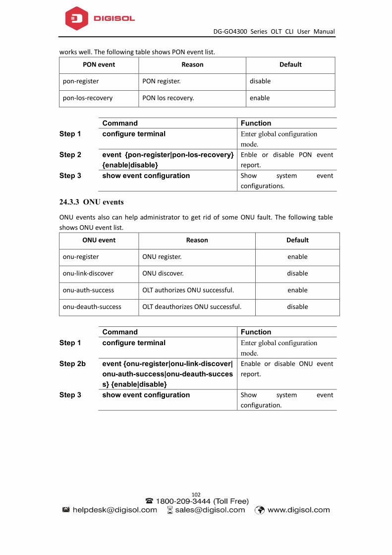
DG-GO4300 Series OLT CLI User Manual
102
works well. The following table shows PON event list.
PON event Reason Default
pon-register PON register. disable
pon-los-recovery PON los recovery. enable
Command Function Step 1 configure terminal Enter global configuration
mode. Step 2 event {pon-register|pon-los-recovery}
{enable|disable} Enble or disable PON event report.
Step 3 show event configuration Show system event configurations.
24.3.3 ONU events
ONU events also can help administrator to get rid of some ONU fault. The following table shows ONU event list.
ONU event Reason Default
onu-register ONU register. enable
onu-link-discover ONU discover. disable
onu-auth-success OLT authorizes ONU successful. enable
onu-deauth-success OLT deauthorizes ONU successful. disable
Command Function Step 1 configure terminal Enter global configuration
mode. Step 2b event {onu-register|onu-link-discover|
onu-auth-success|onu-deauth-success} {enable|disable}
Enable or disable ONU event report.
Step 3 show event configuration Show system event configuration.

DG-GO4300 Series OLT CLI User Manual
103
25 System Log
25.1 System log introduction
System log is mainly used to record running condition and user operant behavior of the whole system. It is helpful for administrator to know and monitor system working condition, record abnormal information. System log comes from all the running module of system. Log system gather, manage, save and display the information. It can be shown in the deivce when you need to debug or check system status, and also can be sent to a server for long-term running status and operation tracking.
25.1.1 Log type
System log has five types: Abnormal information log
Abnormal information log mainly records the abnormal phenomenon of each module, such as abnormal response, inside state machine error, key process execute error and so on.
Alarm log Alarm log mainly records the information from alarm module. Critical alarm, major alarm, minor alarm and warning are corresponding with alerts, critical, major, warnings log level respectively.
Event log Event log mainly records the information from event module. Critical event, major event, minor event and warning are corresponding with alerts, critical, major, warnings log level respectively.
Operation log Operation log mainly records the informations from CLI and SNMP.
Debug log Debug log mainly records the information from networking debugging, such as received IGMP messages, RSTP BPDU messages, state machine skip and so on.
25.1.2 System log level
Syslog information level reference:
Log level Log contrast 7:emergencies Abnormal log
6:alerts Alarm/event log(urgent) Abnormal log
5:critical Alarm/event log(major) Abnormal log
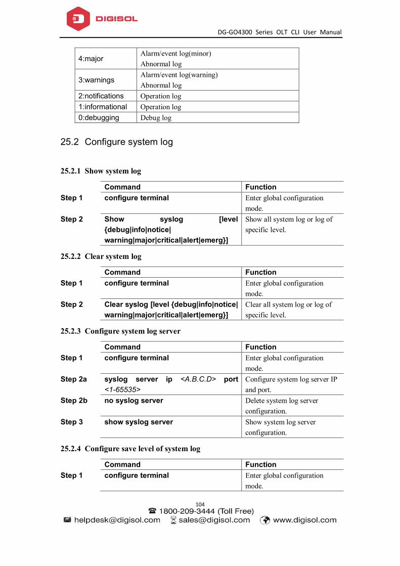
DG-GO4300 Series OLT CLI User Manual
104
4:major Alarm/event log(minor) Abnormal log
3:warnings Alarm/event log(warning) Abnormal log
2:notifications Operation log 1:informational Operation log 0:debugging Debug log
25.2 Configure system log
25.2.1 Show system log
Command Function Step 1 configure terminal Enter global configuration
mode. Step 2 Show syslog [level
{debug|info|notice| warning|major|critical|alert|emerg}]
Show all system log or log of specific level.
25.2.2 Clear system log
Command Function Step 1 configure terminal Enter global configuration
mode. Step 2 Clear syslog [level {debug|info|notice|
warning|major|critical|alert|emerg}] Clear all system log or log of specific level.
25.2.3 Configure system log server
Command Function Step 1 configure terminal Enter global configuration
mode. Step 2a syslog server ip <A.B.C.D> port
<1-65535> Configure system log server IP and port.
Step 2b no syslog server Delete system log server configuration.
Step 3 show syslog server Show system log server configuration.
25.2.4 Configure save level of system log
Command Function Step 1 configure terminal Enter global configuration
mode.
DG-GO4300 Series OLT CLI User Manual
105
Step 2 syslog flash level {debug|info|notice| warning|major|critical|alert|emerg}
System log will be saved to flash if it is higher than you set.
Step 3 show syslog flash level Show system log level in flash.
25.2.5 Save system log to flash
Command Function Step 1 configure terminal Enter global configuration
mode. Step 2 save syslog flash Save system log to flash.
25.2.6 Clear system log in flash
Command Function Step 1 configure terminal Enter global configuration
mode. Step 2 clear syslog flash Clear system log in flash.
25.2.7 Upload system log
Command Function Step 1 configure terminal Enter global configuration
mode. Step 2 upload tftp syslog <filename>
<A.B.C.D> Upload system log to local host byTFTP.