GP3000H Conversion Adapter Installation Guide · Power Supply Input Voltage DC 24 V Rated Voltage...
16
1 GP3000H Conversion Adapter Installation Guide Thank you for purchasing Pro-face’s GP3000H Conversion Adapter (Hereafter referred to as “this adapter”). This adapter converts the cable connector on the GP3000H Series to a terminal block. Safety Cautions • Be sure to check that the unit’s power is disconnected before installing the unit, in order to prevent an electrical shock. • Do not attempt to modify this adapter, due to the dangers of shock and fire. • Prior to installing this adapter, be sure to read this Installation Guide completely. To Prevent Accidents • Do not allow water, liquids or metal particles are not allowed to contact this adapter . Any of these may cause either a breakdown or an electrical shock. • Do not place or store this adapter in a location where there is direct sunlight, excessive heat, dust or vibration. • Do not store or use this adapter near chemicals, or where there are chemical fumes. • Do not use this adapter in locations where corrosive gasses are present. • Do not touch this adapter’s contact terminals. Touching them with a bare finger can lead to corrosion. Unit Disposal • When disposing of this adapter, do so according to your country’s regulations for similar types of industrial waste. Package Contents (1) GP3000H Conversion Adapter (1) (2) M4 Screws (3 types, 4 of each type) (3) Gasket (1) (4) Connector Cover (1) (attached to this adapter) (5) Installation Guide (1) <This Guide> This adapter has been carefully packed, with special attention to quality. However, should you find anything damaged or missing, please contact your local distributor immediately. About the Manual For the detailed information on GP3000H series, refer to the following manual. • GP3000H Series Hardware Manuals • Maintenance/Troubleshooting • GP-Pro EX Reference Manual “Hand Held GP” The manuals can be selected from the help menu of GP-Pro EX or downloaded from Pro-face Home Page. URL http://www.pro-face.com/otasuke/
-
Upload
nguyennhan -
Category
Documents
-
view
220 -
download
1
Transcript of GP3000H Conversion Adapter Installation Guide · Power Supply Input Voltage DC 24 V Rated Voltage...

1
GP3000HConversion Adapter
Installation Guide
Thank you for purchasing Pro-face’s GP3000H Conversion Adapter (Hereafter referred to as “this adapter”).This adapter converts the cable connector on the GP3000H Series to a terminal block.
Safety Cautions
• Be sure to check that the unit’s power is disconnected before installing the unit, in order to prevent an electrical shock.
• Do not attempt to modify this adapter, due to the dangers of shock and fire.
• Prior to installing this adapter, be sure to read this Installation Guide completely.
To Prevent Accidents• Do not allow water, liquids or metal
particles are not allowed to contact this adapter. Any of these may cause either a breakdown or an electrical shock.
• Do not place or store this adapter in a location where there is direct sunlight, excessive heat, dust or vibration.
• Do not store or use this adapter near chemicals, or where there are chemical fumes.
• Do not use this adapter in locations where corrosive gasses are present.
• Do not touch this adapter’s contact terminals. Touching them with a bare finger can lead to corrosion.
Unit Disposal• When disposing of this adapter, do so
according to your country’s regulations for similar types of industrial waste.
Package Contents
(1) GP3000H Conversion Adapter (1)(2) M4 Screws (3 types, 4 of each type)(3) Gasket (1)(4) Connector Cover (1)
(attached to this adapter)(5) Installation Guide (1) <This Guide>This adapter has been carefully packed, with special attention to quality. However, should you find anything damaged or missing, please contact your local distributor immediately.
About the Manual
For the detailed information on GP3000H series, refer to the following manual.• GP3000H Series Hardware Manuals• Maintenance/Troubleshooting• GP-Pro EX Reference Manual “Hand
Held GP”The manuals can be selected from the help menu of GP-Pro EX or downloaded from Pro-face Home Page.URLhttp://www.pro-face.com/otasuke/

2
Part Names and Functions
Name Description
A LED
B Power Switch I: Power ONO: Power OFF
C External Interface
Connect the GP3000H Conversion adapter Connection Cable to the GP.Connection with the GP3000H Conversion Adapter Connection Cable (page 14)
D 24-Pole Terminal Block
Connect DOUT signals and other external outputs, power supply lines, etc. Customer to provide connection cable.
E Rotary Switch
Sets the ID number*1 for this adapter. The [UPPER] and [LOWER] rotary switches are used to make a single ID number (from 0 to 255 (00H to FFH). Set the [UPPER] to the 2nd digit and the [LOWER] to the 1st digit of the two-digit hexadecimal number. (Example: To set 95 (5FH), set the [UPPER] to [5] and the [LOWER] to [F].)
F DIN Rail Hook For mounting to a DIN rail (35 mm [1.38 in.])
Front Rear
A
CD
E
F
Bottom
B
Right SideLeft Side
G
IH
LED Name Color Indicator Status
POWER GreenNot lit Power is OFF.ON Power is ON.
STATUS
GreenON Connected with the GP
(Handshake established)Not lit Power is OFF.
Orange ON Disconnected from the GP(Handshake not established)
RED ON Communication error with the GP adapter is reset.
SEE
3
*1 The GP stores the ID number for the conversion adapter in the system variable [#H_MachineNo] at fixed intervals to make sure it recognizes the conversion adapter is connected to the GP correctly. For details on system variables, refer to the GP-Pro EX Reference Manual.
General Specifications
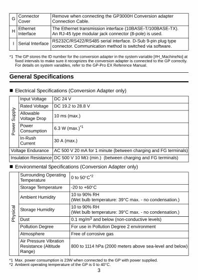
Electrical Specifications (Conversion Adapter only)
Environmental Specifications (Conversion Adapter only)
G Connector Cover
Remove when connecting the GP3000H Conversion adapter Connection Cable.
H Ethernet Interface
The Ethernet transmission interface (10BASE-T/100BASE-TX).An RJ-45 type modular jack connector (8-pole) is used.
I Serial Interface RS232C/RS422/RS485 serial interface. D-Sub 9-pin plug type connector. Communication method is switched via software.
Pow
er S
uppl
y
Input Voltage DC 24 VRated Voltage DC 19.2 to 28.8 VAllowable Voltage Drop 10 ms (max.)
Power Consumption 6.3 W (max.)*1
In-Rush Current 30 A (max.)
Voltage Endurance AC 500 V 20 mA for 1 minute (between charging and FG terminals)Insulation Resistance DC 500 V 10 MΩ (min.) (between charging and FG terminals)
Phy
sica
l
Surrounding Operating Temperature 0 to 50°C*2
Storage Temperature -20 to +60°C
Ambient Humidity 10 to 90% RH (Wet bulb temperature: 39°C max. - no condensation.)
Storage Humidity 10 to 90% RH (Wet bulb temperature: 39°C max. - no condensation.)
Dust 0.1 mg/m3 and below (non-conductive levels)Pollution Degree For use in Pollution Degree 2 environmentAtmosphere Free of corrosive gasAir Pressure Vibration Resistance (Altitude Range)
800 to 1114 hPa (2000 meters above sea-level and below)
*1 Max. power consumption is 23W when connected to the GP with power supplied.*2 Ambient operating temperature of the GP is 0 to 40°C.

4
Structural Specifications
External Interfaces
• This adapter’s serial interface is not isolated. When the host (PLC) unit is also not isolated, and to reduce the risk of damaging the RS232C/RS422/RS485 circuit, be sure to connect pin #5 SG (Signal Ground) terminal.
• When isolation is necessary, you can use the RS232C isolation unit (CA3-ISO232-01) on COM.
1. Serial Interface (COM)
Communication method:RS232C/RS422/RS485
Asynchronous communication methodData length:7 bit/8 bitParity: Odd/Even/NoneStop bit: 1 bit/2 bitBaud rate: 2400 bps to 115.2 kbps
187.5 kbps (MPI)Max. communication distance*1:
15 m (RS232C),1200 m (RS422, 115.2 kbps)
*1 Includes length of GP3000H Conversion Adapter Connection Cable between the GP and this adapter.
Mec
hani
cal
Vibration Resistance
Complies with IEC61131-25 to 9 Hz single-amplitude 3.5 mm [0.14 in.]9 to 150 Hz constant-accelerated velocity 9.8 m/s2
X,Y,Z directions for 10 cycles (100 minutes)
Impact Resistance Comply with IEC61131-2(147 m/s2 to three times X, Y, Z each directions)
Ele
ctric
al Noise Immunity
Noise Voltage: 1000 VP-PPulse Duration: 1 µsRise Time: 1 ns(via noise simulator)
Electrostatic Discharge Immunity
Contact Electrical Discharge6 kV (complies with EN61000-4-2 Level 3)
Inst
alla
tion
Grounding Grounding resistance of 100 Ω 2 mm2 or thicker wire, or your country's applicable standard. (Same for FG and SG terminals)
StructureRating: Equivalent to IP65f (When mounted to the panel)Installation configuration: 35mm [1.38 in.] DIN rail or panel mounted
Cooling Method Natural air circulationWeight Approx. 600 g [1.32 lb] max. (adapter only)External Dimensions W 113 mm [4.45 in.] x H 144 mm [5.67 in.] x D 100 mm [3.94 in.]
Panel Cut Dimensions
W 64.5 mm [2.54 in.] x H 90.5 mm [3.56 in.]*1Panel board thickness: 1.6 mm [0.06 in.] to 10.0 mm [0.39 in.]
*1 All dimensions are held within +1 / -0 mm [+0.04/-0 in.] tolerance, corners finished to R3 or less.

5
2. Ethernet Interface
IEEE802.3u, 10BASE-T/100BASE-TXMax. communication distance*1: 100m
*1 Includes length of GP3000H Conversion Adapter Connection Cable between the GP and this adapter.
3. 24-Pole Terminal Block
• To avoid electrical shock hazards, always turn OFF the power switch on this adapter before connecting or disconnecting the cable.
• When constructing your own cable, check the pin numbers indicated on the terminal block cover before wiring the cable.
• Remove the terminal block from the panel when connecting cables to prevent damage to this adapter and/or the panel.
• To avoid electrical shock hazards, always use terminal blocks covers on terminal blocks.
Recommended Cable Connector XM2D-0901 <made by OMRON Corp.>Recommended Jack Screw #4/40 (UNC) XM2Z-0073 <made by OMRON Corp.>Recommended Cable Cover XM2S-0913 <made by OMRON Corp.>
Pin #RS232C RS422/RS485
Signal Name Description Signal Name Description1 CD Carrier Detect RDA Receive Data A(+)2 RD(RXD) Receive Data RDB Receive Data B(-)3 SD(TXD) Send Data SDA Send Data A(+)4 ER(DTR) Data Terminal Ready ERA Data Terminal Ready A(+)5 SG Signal Ground SG Signal Ground6 DR(DSR) Data Set Ready CSB Clear to Send B(-)7 RS(RTS) Request to Send SDB Send Data B(-)8 CS(CTS) Clear to Send CSA Clear to Send A(+)
9 CI(RI)/VCC Called status display/+5V±5% Output 0.25A*1
*1 The RI/VCC selection for Pin #9 is switched via software. The VCC output is not protected against overcurrent. To prevent damage or unit malfunctions, use only the rated current.
ERB Data Terminal Ready B(-)
Shell FG Frame Ground (Common with SG) FG Frame Ground
(Common with SG)

6
Pin Arrangement Pin No. Signal Name Description
1 DC24V Power Input DC24V2 0V Power Input 0V3 FG Frame Ground (Common with SG)
4 KEY_COM*1
*1 [KEY_COM] terminal is used as a power source for the external safety circuit when developing the external safety circuit using GP's Key Switch. When this adapter's power on, DC24V is output. Do not connect pin #4 [KEY_COM] to touch any other terminals. For the details, "Safety Circuit" on page 10.
Key Switch Common.When this adapter’s power on, DC24V is output. Rating: DC24V±20%, 200mA
5 KEY_NO Key Switch a-contact (normally open)6 KEY_NC Key Switch b-contact (normally closed)
7 ENB0A3-position operation switch 0A (a-contact:normally open)Rating: DC30V, 700mA (Minimum applicable load: DC3V, 5mA)
8 ENB0B 3-position operation switch 0B (a-contact : normally open)
9 ENB1A3-position operation switch 1A (a-contact : normally open)Rating: DC30V, 700mA (Minimum applicable load: DC3V, 5mA)
10 ENB1B 3-position operation switch 1B (a-contact : normally open)
11 EMG0AEmergency switch 0A (a-contact : normally open)Rating: DC30V, 1A (Minimum applicable load: DC5V, 1mA)
12 EMG0B Emergency switch 0B (a-contact : normally open)
13 EMG1AEmergency switch 1A (b-contact : normally closed)Rating: DC30V, 1A (Minimum applicable load: DC5V, 1mA)
14 EMG1B Emergency switch 1B (b-contact : normally closed)
15 EMG2AEmergency switch 2A (b-contact : normally closed)Rating: DC30V, 1A (Minimum applicable load: DC5V, 1mA)
16 EMG2B Emergency switch 2B (b-contact : normally closed)
17 OP OP. OutputOpen collector: DC24V, 300mA
18 OP_GND OP. GND
19 DOUT1 DOUT1 OutputOpen collector: DC24V, 300mA
20 DOUT1_GND DOUT1 GND
21 DOUT0 DOUT0 OutputOpen collector: DC24V, 300mA
22 DOUT0_GND DOUT0 GND
23 BUZZ Buzzer OutputOpen collector: DC24V, 300mA
24 BUZZER_GND BUZZER GND
(Conversion adapter side)
21
2324

7
• Wrap shield wires with tape or cover with insulation tubes.
• Normally, unplugging or plugging the GP3000H Conversion Adapter Connection Cable from this adapter will trigger an emergency stop at the connected device. However, the cable can be plugged or unplugged without causing an emergency stop by providing an external safety circuit. Read the section, “Safety Circuit” on page 10.
Wiring TerminalsUse crimp-type terminals that meet these conditions.
• Use crimp-type terminals with an insulated sleeve. Wrap with tape or cover with a tube if using non-insulated crimp-type terminals.
• The tightening torque for terminal screws is 0.79 N•m [7.0 Lb·In.].
• Connect no more than 2 wires to each terminal.
Power Supply Input Interface
• To avoid an electric shock, prior to connecting this adapter’s power cord terminals to the power terminal block, confirm that this adapter’s power supply is completely turned OFF, via a breaker, or similar unit.
• Any other power level can damage both this adapter and the power supply.
• When the FG terminal is connected, be sure the wire is grounded.
• Use the thickest wire size possible (AWG18 to AWG14) and be sure to twist the wires from the ends.
• Use copper conductors only.Power Supply Cautions
• Input and Output signal lines must be separated from the power control cables for operational circuits.
• To improve the noise resistance, be sure to twist the ends of the power cord wires before connecting them to the power supply unit.
• This adapter’s power supply cord should not be bundled with or kept close to main circuit lines (high voltage, high current), or input/output signal lines.
• To reduce noise, make the power cord as short as possible.
• If the supplied voltage exceeds this adapter’s range, connect a voltage transformer.
• Between the line and the ground, be sure to use a low noise power supply. If there is an excess amount of noise, connect a noise reducing transformer.
• The temperature rating of field installed conductors: 75°C only.
• Use voltage and noise reducing transformers with capacities exceeding power consumption value.
• 24V DC input unit must be used with a Class 2 power supply.
• Connect a surge absorber to handle power surges.
• Be sure to ground the surge absorber (E1) separately from this adapter (E2).Select a surge absorber that has a maximum circuit voltage greater than that of the peak voltage of the power supply.
3.8 [0.15] max.Unit: mm [in.]
φ 3.2 [0.13] min.
5.2 [0.20] min.
6.0
[0.2
4]
max
.
8
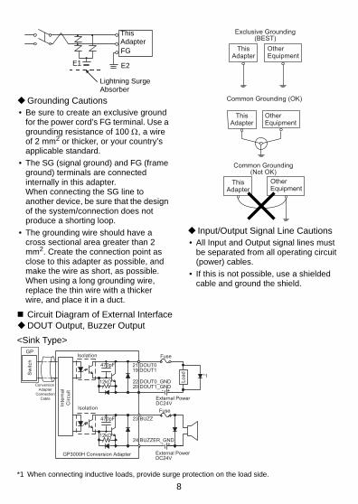
Grounding Cautions• Be sure to create an exclusive ground
for the power cord’s FG terminal. Use a grounding resistance of 100 Ω, a wire of 2 mm2 or thicker, or your country’s applicable standard.
• The SG (signal ground) and FG (frame ground) terminals are connected internally in this adapter.When connecting the SG line to another device, be sure that the design of the system/connection does not produce a shorting loop.
• The grounding wire should have a cross sectional area greater than 2 mm2. Create the connection point as close to this adapter as possible, and make the wire as short, as possible. When using a long grounding wire, replace the thin wire with a thicker wire, and place it in a duct.
Input/Output Signal Line Cautions• All Input and Output signal lines must
be separated from all operating circuit (power) cables.
• If this is not possible, use a shielded cable and ground the shield.
Circuit Diagram of External InterfaceDOUT Output, Buzzer Output
<Sink Type>
*1 When connecting inductive loads, provide surge protection on the load side.
Lightning Surge Absorber
E1 E2
FG
This Adapter
ThisAdapter
OtherEquipment
Exclusive Grounding(BEST)
ThisAdapter
OtherEquipment
Common Grounding (OK)
ThisAdapter
OtherEquipment
Common Grounding(Not OK)
IsolationGP
Isolation
*112kΩ
12kΩ
470pF
470pF
Fuse
Fuse
21 DOUT019 DOUT1
23 BUZZ
22 DOUT0_GND20 DOUT1_GND
24 BUZZER_GND
Load
+-External PowerDC24V
+-
External PowerDC24V
GP3000H Conversion Adapter
Conversion Adapter
Connection Cable
Sw
itch
Inte
rnal
Circ
uit

9
<Source Type>
Operation Switch Output
<Sink Type>
<Source Type>
3-Position Enable Switch Output
*1 When connecting inductive loads, provide surge protection on the load side.
*112kΩ
12kΩ
470pF
470pF
21 DOUT019 DOUT1
23 BUZZ
22 DOUT0_GND20 DOUT1_GND
24 BUZZER_GND
+ -
External PowerDC24V
+ -External PowerDC24V
GP Isolation
Isolation
Fuse
Fuse
Load
GP3000H Conversion Adapter
Conversion Adapter
Connection Cable
Sw
itch
Inte
rnal
Circ
uit
*112kΩ
470pF 17 OP
18 OP_GND +-
GP Isolation Fuse
Load
External PowerDC24V
GP3000H Conversion Adapter
Conversion Adapter
Connection Cable
Sw
itch
Inte
rnal
Circ
uit
*112kΩ
470pF 17 OP
18 OP_GND
+ -GP Isolation Fuse
Load
External PowerDC24V
GP3000H Conversion Adapter
Conversion Adapter
Connection Cable
Sw
itch
Inte
rnal
Circ
uit
3-PositionEnableSwitcha-contact(normally open)
GP3000H Conversion Adapter
GP 7 ENB0A
8 ENB0B
9 ENB1A
10 ENB1B
Load
Load*1 *1
+- External Power
DC30V700 mA max.(However, resistance load)(Smallest applicable load: DC3V 5 mA)
Conversion Adapter
Connection Cable

10
Emergency Switch Output
*1 When connecting inductive loads, provide surge protection on the load side.
Safety Circuit
Normally, unplugging and plugging the GP3000H Conversion Adapter Connection Cable from this adapter will trigger an emergency stop at the connected device. By providing an external “safety circuit”, the cable can be unplugged or plugged without triggering the emergency stop under the conditions described in the followings; “ Conditions to Disable Emergency Stop When External Safety Circuit is Used“. Read this section carefully.
System Design
Safety Circuit
• To avoid an electric shock, prior to connecting this adapter’s power cord terminals to the power terminal block, confirm that this adapter’s power supply is completely turned OFF, via a breaker, or similar unit.
• Connect all wires correctly and test the operation thoroughly after wiring is complete.• If the several failures should be occurred at the same time such as the damage of the
cables or GP’s Key Switch or relays to be deposited or failed to open, it may cause the safety feature deterioration. Be careful to use. The periodic checking of operations would be recommended.
• This safety circuit complies safety category 1 (ISO13849-1).Recommended Safe Relay G7SA-2A2B <made by OMRON Corp.> 8 requiredRecommended Safe Relay Socket P7SA-10F-ND <made by OMRON Corp.> 8 required
Diode Reverse voltage greater than DC250V, low forward voltage type recommended 4 required
Cable AWG26 (UL1061) recommendedPower cord diameter AWG22 to 14 recommended
GP3000H Conversion Adapter
EMG0: a-contact(normally open)EMG1, EMG2: b-contact(normally closed)
13 EMG1A11 EMG0AGP
Con
vers
ion
Ada
pter
C
onne
ctio
n C
able
14 EMG1B12 EMG0B
15 EMG2A
16 EMG2B
Load
Load*1 *1
Load *1
+- External Power
DC30V1 A max.(However, resistance load)(Smallest applicable load: DC5V 1 mA)
GP Unit GP30000HConversion Adapter
Connection Cable
This Adapter Connection Cable(Ex. RS-232C Cable, CA3-CBL232/5M-01)
Host Controller,PLC etc.
Safety Circuit EmergencyStop Circuit
11
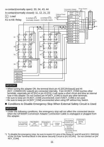
• When turning this adapter ON, the terminal block pin #1 [DC24V(input)] and #4 [KEY_COM(DC24V output)] are connected internally. If pin #4 [KEY_COM] touches other terminals, especially pin #2 [0V] or pin #3 [FG], it will cause a short circuit and blow an internal fuse in this adapter. Do not connect pin #4 [KEY_COM] to touch any other terminals.
• Be sure to keep pin #4 [KEY_COM] unconnected, even if [KEY_COM] is not used.• Be sure to keep pin #4 [KEY_COM] unconnected when using GP without Key Switch.
Conditions to Disable Emergency Stop When External Safety Circuit is Used
• Under the following conditions, the emergency stop will not affect the connected device when the GP3000H Conversion Adapter Connection Cable is unplugged or plugged from this adapter.
*1 To disable the emergency stop, be sure to rewire #11 pins of the Relay K1 and K5 and [#11 EMG0A] of the 24-Pole Terminal Block in the above Security Circuit to [#1 DC24V]. Do not connect on [#4 KEY_COM].
EMG1AEMG1BEMG2AEMG2B
L+-
L+-
L+-
L+-
L+-
L+-
KEY_COM 40V 2DC24V 1
5613141516
KEY_NOKEY_NCEMG1AEMG1BEMG2AEMG2B
1112
EMG0AEMG0B
D1 D2
K1
K2
K3
K4
K5
K6
K7
K8
D3 D4
L+-
+-
0
1 21 22 43 44
11 12 33 34
0
1 21 22 43 44
11 12 33 34
0
1 21 22 43 44
11 12 33 34
0
1 21 22 43 44
11 12 33 34
0
1 21 22 43 44
11 12 33 34
0
1 21 22 43 44
11 12 33 34
0
1 21 22 43 44
11 12 33 34
0
1 21 22 43 44
11 12 33 34
L+-
Conversion Adapter24-Pole Terminal Block
InternalCircuit
External PowerDC24V
SignalName
PinNo.
Connection toExternal Equipment
b-contact(normally closed)
a-contact(normally open)
GPPower Switch
OFF
ON
KeySwitch
Con
nect
ion
Cab
le
Inte
rnal
Circ
uit
a-contact(normally open): 33, 34, 43, 44b-contact(normally closed): 11, 12, 21, 22
: LoadK1 to K8: Relay L
This AdapterPOWER ON
This AdapterPOWER OFFKey Switch
OFF(GP OFF) Connected
DeviceIn Operation
EmergencySwitchOFF
UnplugCable
ConnectedDeviceStop *1
* Connected device will not stop.

12
Dimensions
1. Dimensions
2. Cable Attached Dimensions
25 [0.98]
Unit: mm [in.]
44[1.73]
144
[5.6
7]64 [2.52]
Front
113 [4.45]
90 [3
.54]
Top
Right Side
56[2.20]
41[1
.61]
Unit: mm [in.]24 [0.94]
90
[3.5
4]
Front
57
[2.2
4] (E
ther
net P
ort)
Rear Side
Bottom
103
[4.0
6] (S
eria
l Por
t)
Left Side
(Ext
erna
l Int
erfa
ce)
Top
Right Side
41 [1
.61]
84 [3
.31]

13
Installation
Prior to installing the GP3000H Conversion Adapter:• Be sure that the main power supply is
turned completely OFF before connecting this adapter.
1. Installation and Removal from the 35mm [1.38in.] DIN Rail
InstallationPlace this adapter’s curved, top lip over the top of the DIN rail, and then tilt this adapter down until the bottom face DIN rail clip clicks into place. At the end, be sure to push and secure the DIN rail hook in the direction indicated by the arrow.
• Be sure that the top and bottom faces of this adapter are facing the correct direction and this adapter is installed in a vertical position. Incorrect installation may prevent heat from dissipating.
• The DIN rail clip can be set to remain open. When attaching this adapter to the DIN rail, be sure the DIN rail clip is completely closed and confirm that this adapter is held securely on the DIN rail.
• When attaching this adapter to a DIN rail, be sure to fix the cable in place so that the cable connected is supported and does not place a weight load on the connector. If the cable’s weight is not supported, it may eventually damage this adapter or the DIN rail.
RemovalUse a slot screwdriver to force this adapter’s DIN rail clip down until the bottom of this adapter is freed from the rail. Next, tilt this adapter up and remove.
2. Panel Installation and Removal
(1) Drill installation holes in the panel according to the dimensions given below.
(2) Place this adapter on a flat, level surface facing the rear face downwards. Be sure to insert the gasket into this adapter’s groove so that the gasket’s groove sides are vertical.
DIN Rail
Conversion Adapter
Push in until you hear a click.
Finish by pushing and securing the DIN rail hook upwards.
Conversion Adapter
DIN Rail
DownSlot Screwdriver
Installation Groove
Adapter Front Face
Gasket Seam
Gasket

14
• It is strongly recommended that you use the installation gasket, since it absorbs vibration in addition to repelling water.
• A gasket which has been used for a long period of time may have scratches or dirt on it, and could have lost much of its water resistance which is equivalent to IP65f. Be sure to change the gasket at least once a year, or when scratches or dirt become visible.
• This adapter installation gasket’s model number is “GP3000H-WPGADP-01”.
• The gasket must be inserted correctly into the groove for this adapter’s moisture resistance to be equivalent to IP65f.
• Since the gasket is flexible but not elastic, be careful not to stretch it unnecessarily, as doing so could tear the gasket.
• Be sure the gasket’s seam is not inserted into any of this adapter’s corners, only in the straight sections of the groove. Inserting it into a corner may lead to its eventually tearing.
• To ensure stable resistance against dust and moisture, insert the gasket so that the seam is at the bottom of this adapter.
• The upper surface of the gasket should protrude approximately 2.0 mm [0.08 in.] out from the groove. Be sure to check that the gasket is correctly inserted before installing this adapter into a panel.
(3) Insert the front of this adapter through the panel from the rear.
(4) Use M4 screws to attach the unit. A torque of only 0.5 to 0.6 N•m is sufficient.
Appropriate lengths for M4 screws by panel thickness are listed below.
• Tightening the screws with too much force can damage this adapter.
Connection with the GP3000H Conversion Adapter Connection Cable
1. GP3000H Conversion Adapter Connection Cable
The following GP3000H Conversion Adapter Connection Cable (optional) is required to connect with the GP.
Unit: mm [in.]
2.0 [0.08]
Panel Thickness (mm)[in.] Screws1.6[0.06] to 4[0.16] M4 x 65[0.20] to 7[0.28] M4 x 12
8[0.31] to 10[0.39] M4 x 15
4-φ5.5±0.5
[0.22±0.02]
90.5
[
3.56
](O
peni
ng)
4-R3 [0.12]
max.64.5 (Opening)[2.54 ]
77±0.5 [3.03±0.02]
(Hole locations)
+1–0
+0.04–0
+1 –0+0
.04
–0
85±0
.5 [3
.35±
0.02
](H
ole
loca
tions
)
Unit: mm [in.]
15
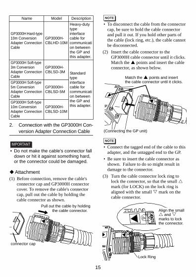
2. Connection with the GP3000H Con-version Adapter Connection Cable
• Do not make the cable's connector fall down or hit it against something hard, or the connector could be damaged.
Attachment(1) Before connection, remove the cable's
connector cap and GP3000H connector cover. To remove the cable's connector cap, pull out the cable by holding the cable connector as shown.
• To disconnect the cable from the connector cap, be sure to hold the cable connector and pull it out. If you hold other parts of the cable (lock ring, etc.), the cable cannot be disconnected.
(2) Insert the cable connector to the GP3000H cable connector until it clicks. Match the points and insert the cable connector, as shown below.
• Connect the tagged end of the cable to this adapter, and the untagged end to the GP.
• Be sure to insert the cable connector as shown. Failure to do so might result in damage to the connector.
(3) Turn the cable connector lock ring to lock the connector, so that the small mark (for LOCK) on the lock ring is aligned with the small mark on the cable connector.
Name Model Description
GP3000H Hard-type 10m Conversion Adapter Connection Cable
GP3000H-CBLHD-10M
Heavy-duty type interface cable for communication between the GP and this adapter.
GP3000H Soft-type 3m Conversion Adapter Connection Cable
GP3000H-CBLSD-3M Standard
type interface cable for communication between the GP and this adapter.
GP3000H Soft-type 5m Conversion Adapter Connection Cable
GP3000H-CBLSD-5M
GP3000H Soft-type 10m Conversion Adapter Connection Cable
GP3000H-CBLSD-10M
connector cap
Pull out the cable by holdingthe cable connector.
Match the points and insert the cable connector until it clicks.
(Connecting the GP unit)
Lock Ring
Align the small and
marks to lock the connector.

16
Removal(1) Unlock the connector that has been
locked in the mounting procedure. (Turn the lock ring as shown so that the small
mark is displaced from the mark). Then, pull out the cable by holding the cable connector.
• If this adapter is to be used in an environment where it may come in contact with water, cover the connector with a connector cover whenever the cable is removed.
• To disconnect the cable, be sure to hold the cable’s connector and pull it out. If you hold other parts of the cable (lock ring, etc.), the cable cannot be disconnected.
UL/c-UL Approval
The following unit is UL/c-UL listed product:(UL File No.E220851)
The product conforms to the following standards:
UL508Industrial Control Equipment
CSA-C22.2 No.142-M1987 (c-UL Approval)
Standard for Process Control Equipment
<Cautions>Be aware of the following items when building this adapter into an end-use product:• This adapter is approved as an open-
type unit.• This adapter must be used indoors
only.• For use on a flat surface of a Type 1
Enclosure.• The unit’s Front surface is not
approved as an enclosure. Therefore, provide a fireproof enclosure (metal barrier) that entirely covers the unit rear and lateral faces.
CE Marking
• AGP3000H-ADPCOM-01 is a CE marking product complying with the EMC Directive. This unit also conforms to EN55011 Class A, EN61000-6-2 directives.
Digital Electronics Corporation8-2-52 Nanko-higashiSuminoe-ku, Osaka 559-0031JAPANTEL: +81-(0)6-6613-3116FAX: +81-(0)6-6613-5888http://www.pro-face.com/
The information in this document is subject to change without notice.
© Copyright 2008 Digital Electronics Corporation.All rights reserved.PFX102974F .AGP3000H-ADPCOM-MT01E-BTH2012.01 JM/E
Product Model No.UL/c-UL
Registration Model No.
AGP3000H-ADPCOM-01 3610006-01
2. Pull out the cable by holding the cable connector.
1. Turn the lock ring to unlock the connector.
InquiryDo you have any questions or comments about this product? Please access our site any time if you need help with a solution.http://www.pro-face.com/otasuke/
Please be aware that Digital Electronics Corporation shall not be held liable by the user for any damages, losses, or third party claims arising from the uses of this product.
Note