GP Dimming Panels 120-127 / 277 Voltsite.electricsuppliesonline.com/documents/Lutron/gp_120.pdf ·...
25
R Job Name: Job Number: Model Numbers: Page SPECIFICATION SUBMITTAL gp-1 06.15.04 Power Equipment GP Dimming Panels GRAFIK Systems GP Dimming Panels 120-127 / 277 Volt GP3/4 Mini Panels GP36 Large-Size Panels GP8-24 Standard-Size Panels GP48-144 Large-Size Panels GP Dimming Panels provide power and dimming for up to 144 load circuits and control any light source, including full-conduction non-dim. Models available with: • 120-127 V and 277 V input power. • 3 to 144 circuits. • Different feed types and breakers. GP Dimming Panels work with: • GRAFIK Eye 4000 Control Units. • GRAFIK 5000TM, GRAFIK 6000®, and GRAFIK 7000® Systems. • LP Dimming Panels. • XP SoftswitchTM Panels. • DMX512 dimming systems via the 2LINKTM option.
Transcript of GP Dimming Panels 120-127 / 277 Voltsite.electricsuppliesonline.com/documents/Lutron/gp_120.pdf ·...

R
Job Name:
Job Number:
Model Numbers:
PageSPECIF ICATION SUBMITTAL
gp-1 06.15.04
Power EquipmentGP Dimming PanelsGRAFIK Systems
GP Dimming Panels120-127 / 277 Volt
GP3/4Mini
Panels
GP36Large-Size Panels
GP8-24 Standard-Size
Panels
GP48-144Large-Size Panels
GP Dimming Panels provide powerand dimming for up to 144 loadcircuits and control any light source,including full-conduction non-dim.
Models available with:
• 120-127 V and 277 V input power.• 3 to 144 circuits.• Different feed types and breakers.
GP Dimming Panels work with:
• GRAFIK Eye 4000 Control Units.• GRAFIK 5000TM, GRAFIK 6000®,
and GRAFIK 7000® Systems.• LP Dimming Panels.• XP SoftswitchTM Panels.• DMX512 dimming systems via the
2LINKTM option.
R
Job Name:
Job Number:
Model Numbers:
PageSPECIF ICATION SUBMITTAL
gp-4 06.15.04
Power EquipmentGP Dimming PanelsGRAFIK Systems
Wiring
• Internal: Prewired by Lutron.• System communications: Low-
voltage Class 2 (PELV) wiringconnects Dimming Panels toother components.
• Line (mains) voltage: Feed, load,and control circuit wiring only.No other wiring or assemblyrequired.
Filter Chokes
• Load current rise time ismeasured at a 90 degreeconduction angle.
• 10-90% of load currentwaveform:- 350µSec rise time at 50%
dimmer capacity.- 400µSec rise time at 100%
dimmer capacity.• 0-100% of load current
waveform:- 525µSec rise time at 50%
dimmer capacity.- 600µSec rise time at 100%
dimmer capacity.• At no point in the waveform can
the rate of current changeexceed 300mA per µSec.
• Consult Lutron for higher risetime options.
Standards
• UL Listed(Reference: UL File 42071).
• Complies with CSA or NOM(where appropriate).
Power
• Input power: 100-127V and 277V,50/60Hz, phase-to-neutral.
• Branch Circuit Capacity:- 120-127V - up to 2000W/VA- 277V - 4500W/VA
• Number of Circuits: 3-144• Branch Circuit Breakers: UL-rated
thermal magnetic.AIC ratings (other ratings available):- 100-127V – 10,000A- 277V – 14,000A
• Lightning strike protection: MeetsANSI/IEEE standard 62.41-1980.Can withstand voltage surges of upto 6000V and current surges of upto 3000A.
• 10-year power failure memory: Automatically restores lighting toscene selected prior to powerinterruption.
Sources/Load Types
Operates these sources with asmooth continuous Square Lawdimming curve or on a fullconduction non-dim basis:
• Incandescent (Tungsten)/Halogen• Magnetic Low Voltage Transformer• Electronic Low Voltage Transformer1
• Lutron Electronic Fluorescent Dimming Ballasts
• Magnetic Fluorescent Lamp Ballasts• Optional modules allow for control of
0-10V, DSI, and PWM load types.• Operates HID sources on a full
conduction non-dim basis.
Dimming Cards
• Panel current ratings are listedfor continuous operation - UL-listed specifically for each lightsource.
• RTISSTM filter circuit technologycompensates for incoming linevoltage variations: No visibleflicker with +/-2% change inRMS voltage/cycle and +/-2%Hz change in frequency/sec-ond.
• Arcless-relay air gap-offswitches (one per load circuit)ensure open load circuits whenoff function selected. Eliminatearcing at mechanical contactswhen loads are switched.
Physical Design
• Enclosure: NEMA-Type 1 (Type2 available upon request), IP-20protection; #16 U.S. GaugeSteel. Indoors only.
• Weight: 30-1300 pounds(14-590kg).
• Mounting: Surface mount only.Allow space for ventilating.
Environment/Heat Dissipation
• Patented, ribbed aluminum heatsink base cools Panel byconvection. No fans.
• 32-104°F (0-40°C). Relativehumidity less than 90%non-condensing.
Specifications - 120-127 / 277 Volt
1 Reverse-phase control transformers require an ELVI PowerInterface. Check phase with transformer manufacturer.

R
Job Name:
Job Number:
Model Numbers:
PageSPECIF ICATION SUBMITTAL
gp-7 06.15.04
Power EquipmentGP Dimming PanelsGRAFIK Systems
Prefix:GP for GP Dimming Panel
Number of Load Circuits:Indicates number of load circuits in the panel
Voltage:120 for 120-127 V277 for 277 V
Feed Type:2 for 1 phase 2 wire3 for 1 phase 3 wire (split phase)4 for 3 phase 4 wire
Panel Feed:ML for Main Lugs onlyMxx for Main Breaker with xx = breaker size in Amps
Branch Circuit Breakers:20 for 20A branch circuit breakers15 for 15A branch circuit breakers
Custom Panel Suffix:Indicates panel with special options
How to Build a GP Model Number
Prefix
Number ofLoad Circuits
Voltage
Feed Type
Panel Feed
Branch Circuit Breakers
Custom Panel Suffix
G P 1 2 - 1 2 0 4 M L - 2 0 - C G P - _ _ _

R
Job Name:
Job Number:
Model Numbers:
PageSPECIF ICATION SUBMITTAL
gp-10 06.15.04
Power EquipmentGP Dimming PanelsGRAFIK Systems
Number Of Circuits
FeedType
MaximumFeed
CircuitBreakers 1
15A20A15A20A15A20A15A3
20A3
GP3
GP4
1Ø, 2W
1Ø, 3W
3Ø, 4W
FeedThrough
40A40A30A40A15A20A20A20A
Only standard panels listed. Consult Lutron for further options.
1 20/16A, 15/12A continuous load rating.2 Measured current will not exceed continuous load rating due to
voltage drop in the dimmer.3 Breakers located in distribution panel supplied by others.
120-127V Power
GP3/4 Mini Models
Number Of Circuits
CircuitBreakers1
FeedType
MaximumFeed
40A20A
20A
1Ø, 2W3Ø, 4W
FeedThrough
GP3
GP4
20A20A
20A3
277V Power
Panel Branch Ratings
MaximumDimmed Hot Load 2
1500W/VA2000W/VA1500W/VA2000W/VA1500W/VA2000W/VA1500W/VA2000W/VA
Panel Branch Ratings
MaximumDimmed Hot Load 2
4500W/VA4500W/VA
4500W/VA

R
Job Name:
Job Number:
Model Numbers:
PageSPECIF ICATION SUBMITTAL
gp-11 06.15.04
Power EquipmentGP Dimming PanelsGRAFIK Systems
Main Lugs Only
Main Lugs Only
60A Main Breaker80A Main Breaker
Main Lugs Only
50A Main Breaker60A Main Breaker
Main Lugs Only
Main Lugs Only
60A Main Breaker80A Main Breaker
Main Lugs Only
125A Main Breaker175A Main Breaker
Main Lugs Only
100A Main Breaker125A Main Breaker
Main Lugs Only
110A Main Breaker150A Main Breaker
Main Lugs Only
125A Main Breaker175A Main Breaker
MaximumFeed
Number Of Circuits
FeedType
CircuitBreakers1
120-127V Power
1Ø, 2W
1Ø, 3W
3Ø, 4W
1Ø, 3W
3Ø, 4W
1Ø, 3W
3Ø, 4W
3Ø, 4W
3Ø, 4W
GP8
GP12
GP16
GP20
GP24
175A175A175A175A60A80A175A175A50A60A175A175A175A175A60A80A175A175A125A175A175A175A100A125A175A175A110A150A175A175A125A175A
15A20A15A20A15A20A15A20A15A20A15A20A15A20A15A20A15A20A15A20A15A20A15A20A15A20A15A20A15A20A15A20A
PanelFeed
GP8-24 Standard-Size ModelsOnly standard panels listed. Consult Lutron for further options.
1 20/16A, 15/12A continuous load rating.2 Measured current will not exceed continuous load rating due to voltage drop in the dimmer.
Panel Branch Ratings
MaximumDimmed Hot Load 2
1500W/VA2000W/VA1500W/VA2000W/VA1500W/VA2000W/VA1500W/VA2000W/VA1500W/VA2000W/VA1500W/VA2000W/VA1500W/VA2000W/VA1500W/VA2000W/VA1500W/VA2000W/VA1500W/VA2000W/VA1500W/VA2000W/VA1500W/VA2000W/VA1500W/VA2000W/VA1500W/VA2000W/VA1500W/VA2000W/VA1500W/VA2000W/VA

R
Job Name:
Job Number:
Model Numbers:
PageSPECIF ICATION SUBMITTAL
gp-12 06.15.04
Power EquipmentGP Dimming PanelsGRAFIK Systems
175A175A60A175A80A175A125A
Main Lugs OnlyMain Lugs Only60A Main BreakerMain Lugs Only80A Main BreakerMain Lugs Only125A Main Breaker
1Ø, 2W
3Ø, 4W
3Ø, 4W
3Ø, 4W
GP8
GP12
GP16
20A20A20A20A20A20A20A
277V Power
MaximumFeed
Number Of Circuits
FeedType
CircuitBreakers1
PanelFeed
GP8-24 Standard-Size ModelsOnly standard panels listed. Consult Lutron for further options.
1 20/16A, 15/12A continuous load rating.2 Measured current will not exceed continuous load rating due to voltage drop in the dimmer.
Panel Branch Ratings
MaximumDimmed Hot Load 2
4500W/VA4500W/VA4500W/VA4500W/VA4500W/VA4500W/VA4500W/VA

R
Job Name:
Job Number:
Model Numbers:
PageSPECIF ICATION SUBMITTAL
gp-13 06.15.04
Power EquipmentGP Dimming PanelsGRAFIK Systems
750A750A200A250A750A750A250A350A750A750A300A400A750A750A350A400A750A750A
Main Lugs Only
200A Main Breaker250A Main Breaker
Main Lugs Only
250A Main Breaker350A Main Breaker
Main Lugs Only
300A Main Breaker400A Main Breaker
Main Lugs Only
350A MainBreaker400A Main Breaker
Main Lugs Only
3Ø, 4W
3Ø, 4W
3Ø, 4W
3Ø, 4W
3Ø, 4W
GP36
GP48
GP60
GP72
GP144
15A20A15A20A15A20A15A20A15A20A15A20A15A20A15A20A15A20A
120-127V Power
MaximumFeed
Number Of Circuits
FeedType
CircuitBreakers1
PanelFeed
GP36-144 Large-Size ModelsOnly standard panels listed. Consult Lutron for further options.
20A20A20A20A20A20A20A20A
20A
Main Lugs Only
250A Main BreakerMain Lugs Only350A Main BreakerMain Lugs Only400A Main BreakerMain Lugs Only400A Main BreakerMain Lugs Only
3Ø, 4W
3Ø, 4W
3Ø, 4W
3Ø, 4W
3Ø, 4W
GP36
GP48
GP60
GP72
GP144
750A250A750A350A750A400A750A400A750A
277V Power
MaximumFeed
Number Of Circuits
FeedType
CircuitBreakers1
PanelFeed
1 20/16A, 15/12A continuous load rating.2 Measured current will not exceed continuous load rating due to voltage drop in the dimmer.
Panel Branch Ratings
MaximumDimmed Hot Load 2
Panel Branch Ratings
MaximumDimmed Hot Load 2
1500W/VA2000W/VA1500W/VA2000W/VA1500W/VA2000W/VA1500W/VA2000W/VA1500W/VA2000W/VA1500W/VA2000W/VA1500W/VA2000W/VA1500W/VA2000W/VA1500W/VA2000W/VA
4500W/VA4500W/VA4500W/VA4500W/VA4500W/VA4500W/VA4500W/VA4500W/VA
4500W/VA

R
Job Name:
Job Number:
Model Numbers:
PageSPECIF ICATION SUBMITTAL
gp-16 06.15.04
Power EquipmentGP Dimming PanelsGRAFIK Systems
Dimensions for GP3/4 Mini Panels
19 1/2"(495mm)
21 1/8"(537mm)
18"(457mm)
Top View
3 5/8”(92 mm) 6 1/4”
(160 mm)
9 5/8”(244 mm)
18”(457 mm)
19 1/2”(495 mm)
1 1/8”(29 mm)
2 3/4”(70 mm)
1 1/8”(29 mm)
1 3/16”(30 mm)
2 3/4”(70 mm)
5 1/4”(133 mm)
21 1/8”(537 mm)
11”(279 mm)
2 3/4”(70 mm)
1 1/2”(38 mm)
1 1/2”(38 mm)5 1/2”
(140 mm)
1 5/8”(41 mm)
5 1/8”(130 mm)
Left Side View Front View
Bottom View
Keyhole accepts a maximumof 1/4” (6mm) mounting bolt.#10 M6 recommended.
Load CircuitWiring Feed Wiring
Class 2 (PELV)Wiring
Right Side View

R
Job Name:
Job Number:
Model Numbers:
PageSPECIF ICATION SUBMITTAL
gp-17 06.15.04
Power EquipmentGP Dimming PanelsGRAFIK Systems
Dimensions for GP8-24 Standard-Size Panels
Top View
Front View Right SideLeft Side
Bottom ViewKeyhole accepts a maximum of 5/16" (8 mm)mounting bolt (1/4" (m8) recommended).Class 2/PELV entry knockout is 7/8" dia. (22 mm)
Suggested feedwiring entry
Removable top cover is shipped inthe same box as the panel.
Required controlwiring entry
Suggested loadwiring entry
28”(711 mm)
37”(940 mm)
35”(889 mm)
12”(304 mm) 12”
(304 mm)
13”(330 mm)
33”(838 mm)
2”(50 mm)
2”(50 mm)
2”(50 mm)
4”(100 mm)
R
Job Name:
Job Number:
Model Numbers:
PageSPECIF ICATION SUBMITTAL
gp-18 06.15.04
Power EquipmentGP Dimming PanelsGRAFIK Systems
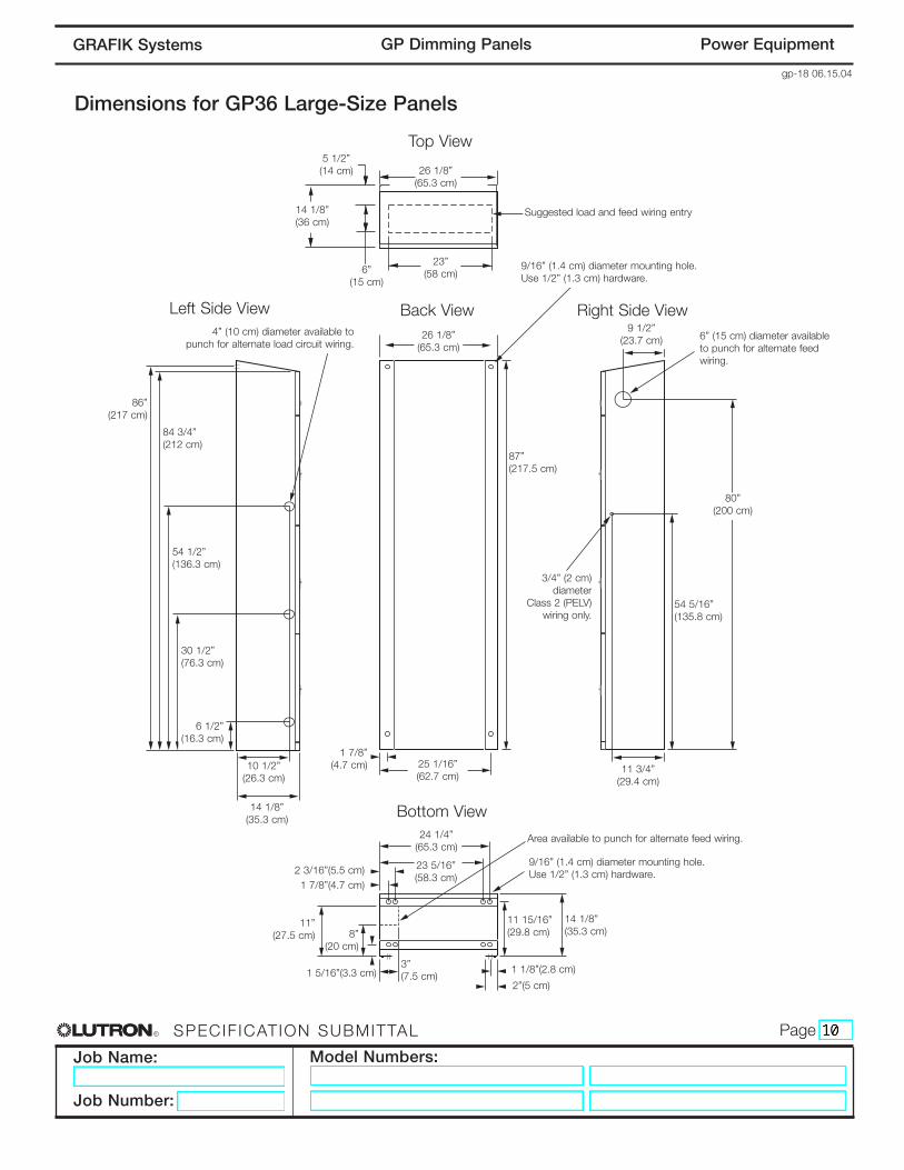
Dimensions for GP36 Large-Size Panels
Top View
9 1/2”(23.7 cm)
87”(217.5 cm)
84 3/4”(212 cm)
80”(200 cm)
86”(217 cm)
1 7/8”(4.7 cm)
6 1/2”(16.3 cm)
11”(27.5 cm) 8”
(20 cm)
54 5/16”(135.8 cm)
54 1/2”(136.3 cm)
30 1/2”(76.3 cm)
11 15/16”(29.8 cm)
14 1/8”(35.3 cm)
26 1/8”(65.3 cm)
25 1/16”(62.7 cm)
24 1/4”(65.3 cm)
3”(7.5 cm)
23 5/16”(58.3 cm)
2 3/16”(5.5 cm)
1 5/16”(3.3 cm) 1 1/8”(2.8 cm)
2”(5 cm)
1 7/8”(4.7 cm)
10 1/2”(26.3 cm)
11 3/4”(29.4 cm)
14 1/8”(35.3 cm)
26 1/8”(65.3 cm)
14 1/8”(36 cm)
23”(58 cm)
5 1/2”(14 cm)
6”(15 cm)
Left Side View Back View
Bottom View
Suggested load and feed wiring entry
9/16” (1.4 cm) diameter mounting hole.Use 1/2” (1.3 cm) hardware.
9/16” (1.4 cm) diameter mounting hole.Use 1/2” (1.3 cm) hardware.
6” (15 cm) diameter availableto punch for alternate feedwiring.
3/4” (2 cm)diameter
Class 2 (PELV)wiring only.
Area available to punch for alternate feed wiring.
4” (10 cm) diameter available topunch for alternate load circuit wiring.
Right Side View

R
Job Name:
Job Number:
Model Numbers:
PageSPECIF ICATION SUBMITTAL
gp-19 06.15.04
Power EquipmentGP Dimming PanelsGRAFIK Systems
Dimensions for GP48/60/72 Large-Size Panels
Top View
9 1/2”(23.7 cm)
87”(217.5 cm)
84 3/4”(212 cm)
80”(200 cm)
86”(217 cm)
1 7/8”(4.7 cm)
6 1/2”(16.3 cm)
11”(27.5 cm) 8”
(20 cm)
54 5/16”(135.8 cm)
54 1/2”(136.3 cm)
30 1/2”(76.3 cm)
11 15/16”(29.8 cm)
14 1/8”(35.3 cm)
50”(125 cm)
25 1/16”(62.7 cm) 27 1/4”
(68.1 cm) 51 1/8”(127.8 cm)
24 5/16”(63.3 cm)
23 5/16”(58.3 cm)2 3/16”(5.5 cm)
1 5/16”(3.3 cm)3”(7.5 cm)
28”(70 cm)28 15/16”(72.3 cm)
49 7/16”(123.6 cm)50 7/16”(126.1 cm)
1 7/8”(4.7 cm)
10 1/2”(26.3 cm)
11 3/4”(29.4 cm)
14 1/8”(35.3 cm)
52 5/16”(130.8 cm)
14 1/8”(36 cm)
23”(58 cm)
23”(58 cm)
5 1/2”(14 cm)
6”(15 cm)
Left Side View Back View
Bottom View
Suggested load and feed wiring entry
9/16” (1.4 cm) diameter mounting hole.Use 1/2” (1.3 cm) hardware.
9/16” (1.4 cm) diameter mounting hole.Use 1/2” (1.3 cm) hardware.
6” (15 cm) diameter availableto punch foralternate feedwiring.
3/4” (2 cm)diameter
Class 2 (PELV)wiring only.
Area available to punch for alternate feed wiring.
4” (10 cm) diameter available topunch for alternate load circuit wiring.
Right Side View
R
Job Name:
Job Number:
Model Numbers:
PageSPECIF ICATION SUBMITTAL
gp-20 06.15.04
Power EquipmentGP Dimming PanelsGRAFIK Systems
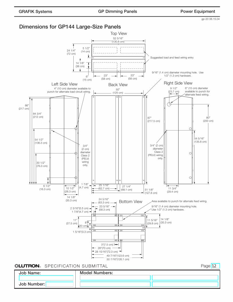
Dimensions for GP144 Large-Size PanelsTop View
9 1/2”(23.7 cm)
87”(217.5 cm)
84 3/4”(212 cm) 80”
(200 cm)
86”(217 cm)
1 7/8”(4.7 cm)6 1/2”
(16.3 cm)
11”(27.5 cm) 8”
(20 cm)
54 5/16”(135.8 cm)
54 1/2”(136.3 cm)
30 1/2”(76.3 cm)
14 1/8”(35.3 cm)
11 5/16”(29.8 cm)
50”(125 cm)
25 1/16”(62.7 cm)
27 1/4”(68.1 cm) 51 1/8”
(127.8 cm)
24 5/16”(63.3 cm)
23 5/16”(58.3 cm)2 3/16”(5.5 cm)
1 5/16”(3.3 cm)
3”(7.5 cm)28”(70 cm)
28 15/16”(72.3 cm)
49 7/16”(123.6 cm)50 7/16”(126.1 cm)
1 7/8”(4.7 cm)
10 1/2”(26.3 cm)
11 3/4”(29.4 cm)
14 1/8”(35.3 cm)
52 5/16”(130.8 cm)
24 1/4”(72 cm)
23”(58 cm)
23”(58 cm)
5 1/2”(14 cm)
6”(15 cm)
Left Side View Back View
Bottom View
Suggested load and feed wiring entry
9/16” (1.4 cm) diameter mounting hole. Use1/2” (1.3 cm) hardware.
9/16” (1.4 cm) diameter mounting hole.Use 1/2” (1.3 cm) hardware.
6” (15 cm) diameter available to punch for alternate feed wiring.
3/4” (2 cm)diameter Class 2
(PELV) wiringonly.
3/4” (2 cm)
diameter Class 2(PELV)wiringonly.
Area available to punch for alternate feed wiring.
4” (10 cm) diameter available topunch for alternate load circuit wiring.
Right Side View
14 1/8”(36 cm)

R
Job Name:
Job Number:
Model Numbers:
PageSPECIF ICATION SUBMITTAL
gp-21 06.15.04
Power EquipmentGP Dimming PanelsGRAFIK Systems
• Surface mount indoors. • Panel generates heat. Mount only where ambient
temperature will be 0-40 °C (32-104 °F).• This equipment is air cooled. Do not block vents or
warranty will be void. Leave 12" (31cm) clearancesabove, below, and in front of Panel. No clearancenecessary on sides.
• Reinforce wall structure for weight and local codes.
Wiring Raceway
LoadCircuitWiring
FeedWiring
BranchCircuitBreakers
TerminalBlocksfor LoadCircuits
Class 2 (PELV)Wiring
12"(31cm)
minimum
12"(31cm)minimumtop andfront
Water damages Panels! Install Panels in a location where they will not get wet.
GP3/4 FrontView
GP3/4 SideView
For maximum Feed and Wire Sizes,consult Wiring Overview page.
• Dimming Panels will hum slightly and internal relayswill click while in operation. Mount where audiblenoise is acceptable.
• Mount Panels so line (mains) voltage wiring is at least6 feet (1.8m) from sound or electronic equipment andwiring.
• GP Panels must be mounted within 7° of truevertical.
GP3/4 Mini Panel Mounting
Panel
GP3/4
MaximumBTUs/Hour
685
Weight(without packaging)
30 lbs. (14kg)

R
Job Name:
Job Number:
Model Numbers:
PageSPECIF ICATION SUBMITTAL
gp-22 06.15.04
Power EquipmentGP Dimming PanelsGRAFIK Systems
• Surface mount indoors. • Panel generates heat. Mount only where ambient
temperature will be 0-40 °C (32-104 °F).• This equipment is air cooled. Do not block vents or
warranty will be void. Leave 12" (31cm) clearancesabove, below, and in front of Panel. Leave clearanceon sides for Class 2 (PELV) wiring.
• Reinforce wall structure for weight and local codes.
Wiring Raceway
FeedWiring
airflow
LoadCircuitWiring
Main Lugs or Main Breaker.
Terminal Blocks for Load Circuits
12" (31cm)minimum
top and front
12"(31cm)
minimum
Water damages Panels! Install Panels in a location where they will not get wet.
GP8-24 FrontView
GP8-24 SideView
For maximum Feed and Wire Sizes,consult Wiring Overview page.
• Dimming Panels will hum slightly and internal relayswill click while in operation. Mount where audiblenoise is acceptable.
• Mount Panels so line (mains) voltage wiring is at least6 feet (1.8m) from sound or electronic equipmentand wiring.
• GP Panels must be mounted within 7° of truevertical.
Class 2(PELV)Wiring
GP8-24 Standard-Size Panel Mounting
Panel
GP8GP12GP16GP20GP24
MaximumBTUs/Hour13652045272534054085
Weight(without packaging)115 lbs. (52kg)130 lbs. (59kg)145 lbs. (66kg)160 lbs. (73kg)175 lbs. (80kg)

R
Job Name:
Job Number:
Model Numbers:
PageSPECIF ICATION SUBMITTAL
gp-23 06.15.04
Power EquipmentGP Dimming PanelsGRAFIK Systems
Class 2 (PELV)Wiring
Class 2 (PELV)Wiring
6" (16cm)minimum1
Wiring Raceway
FeedWiring
air flow
Load CircuitWiring
12"(31cm)
minimum
3' 4 5/8"(103cm)to mountingholes
6' 6"(195cm)NECBreakerHeightLimit
7' 5 5/8"(228cm)to mountingholes
8' 8"(265cm)minimumto ceiling
12"(31cm)
1 6" (16cm) approved for this layout only.
At least 8' 8" (265cm) between the floor and thesuspended ceiling is required for this layout.
GP8-24 SideView
Water damages Panels! Install Panels in a location where they will not get wet.
GP8-24 FrontView
Mounting One Panel Above Another

R
Job Name:
Job Number:
Model Numbers:
PageSPECIF ICATION SUBMITTAL
gp-24 06.15.04
Power EquipmentGP Dimming PanelsGRAFIK Systems
Class 2(PELV)Wiring
Terminal Blocksfor LoadCircuits
MainLugsor MainBreaker
Feed andLoadCircuitWiring
For GP144
only:Extra
Class 2(PELV)Wiring
Raceway
GP36
GP48-144
• Surface mount indoors. • Panel generates heat. Mount only where
ambient temperature will be 0-40 °C (32 -104 °F).
• This equipment is air cooled - do not blockvents or warranty will be void. Leave 12"(31cm) clearances above and in front ofPanel. Leave clearance on sides for Class 2(PELV) wiring.
GP36-144Front View
GP36-72Side View
12"minimumtop andfront
airflow
Wall
Ceiling
Water damages Panels! Install Panels in a location where they won't get wet.
• Mount Panel on floor and against a wall.Use 1/2" (13mm) mounting bolts.
• Dimming Panels will hum slightly andinternal relays will click while in operation.Mount where audible noise is acceptable.
• Mount Panels so line (mains) voltage wiringis at least 6 feet (1.8m) from sound orelectronic equipment and wiring.
• GP Panels must be mounted within 7° oftrue vertical.
GP36 Mounting
GP36 consists of the right side moduleonly. Mount as shown.
GP144 Mounting
• Allow airflow and 3 ft. (92cm) clearance infront and back of GP144 Panel.
• Note the extra Class 2 (PELV) wiring.
Alternate Conduit Locations
• Run Feed Wiring in from bottom.• Run Load Circuit Wiring in from left side.
GP36-144 Large-Size Panel Mounting
Panel
GP36GP48GP60GP72GP144
MaximumBTUs/Hour
435058007250870017400
Weight(without packaging)
325 lbs. (147kg)550 lbs. (250kg)600 lbs. (273kg)650 lbs. (295kg)1300 lbs. 590kg)
GP144 Side View
12"min.
12"min.
3 ft.min.
3 ft.min.
Class 2(PELV)Wiring
airflow
airflow

R
Job Name:
Job Number:
Model Numbers:
PageSPECIF ICATION SUBMITTAL
gp-25 06.15.04
Power EquipmentGP Dimming PanelsGRAFIK Systems
SH1
DH2
SH2
DH3
SH3
DH1
H1
H2
H3
GP3 Mini Panel Wiring Overview120-127 Volt
Wiring Tips
Wire the Mini GP3 similar to wiring alighting Distribution Panel:
• Run feed and load wiring. No otherwiring or assembly required.
• Common Neutrals are not permitted.Run separate Neutrals for each loadcircuit.
The GP3 can provide temporary lighting:
• Wire all loads.• Do not remove the bypass jumpers that
protect the Dimming Modules.• Use Branch Circuit Breakers to switch
lights on and off.
Control Wiring
Power Feed(Hot/Live)
Terminal Block
Neutral Feed
Load
BranchCircuitBreakers
Dimmed Hot/Live Load Neutral
Bypass Jumpers -Do Not Remove
Typical Load Circuit
Ground
Wire Sizes
• Power Feed:#14 AWG (2.0mm2) to #8 AWG (6.0mm2)
• Neutral Feed:#14 AWG (2.0mm2) to #6 AWG (10.0mm2)
• Dimmed Hot/Live:#14 AWG (2.0mm2) to #10 AWG (4.0mm2)
• Load Neutral:#14 AWG (2.0mm2) to #6 AWG (10.0mm2)

R
Job Name:
Job Number:
Model Numbers:
PageSPECIF ICATION SUBMITTAL
gp-28 06.15.04
Power EquipmentGP Dimming PanelsGRAFIK Systems
DH1
SH1
H1
N1
N1
DH2
SH2
H2
N2
N2
Power Feed(Hot/Live)
Terminal Block
Load Dimmed Hot/Live
Bypass Jumpers -Do Not Remove
Typical Dimming Leg
Load Neutral
GP4 Mini Panel Wiring Overview120-127 Volt
Wiring Tips
Wire the GP4 similar to wiring a lightingDistribution Panel:
• Run feed and load wiring. No otherwiring or assembly required.
• Common Neutrals are not permitted.Run separate Neutrals for each loadcircuit.
The GP4 can provide temporary lighting:
• Wire all loads.• Do not remove the bypass jumpers that
protect the Dimming Modules.
Neutral Feed
Ground
Wire Sizes
• Power Feed:#14 AWG (2.0mm2) to #10 AWG (4.0mm2)
• Neutral Feed:#14 AWG (2.0mm2) to #10 AWG (4.0mm2)
• Dimmed Hot/Live:#14 AWG (2.0mm2) to #10 AWG (4.0mm2)
• Load Neutral:#14 AWG (2.0mm2) to #10 AWG (4.0mm2)

R
Job Name:
Job Number:
Model Numbers:
PageSPECIF ICATION SUBMITTAL
gp-31 06.15.04
Power EquipmentGP Dimming PanelsGRAFIK Systems
DH1
SH1
H1
DH1
SH1
Feed Wiring
TerminalBlock
Load Neutral Load
Dimmed Hot/Live
BranchCircuitBreakers
Class 2(PELV)Wiring
Neutral FeedPower Feed (Hot/Live)
BypassJumpers -Do NotRemove
Typical Load Circuit
GP8-24 Standard-Size Panel Wiring Overview
Wiring Tips
Wire the GP8-24 similar to wiring alighting Distribution Panel:
• Run feed and load wiring. No otherwiring or assembly required.
• Common Neutrals are not permitted.Run separate Neutrals for each loadcircuit.
The GP8-24 can provide temporarylighting:
• Wire all loads.• Do not remove the bypass jumpers
that protect the Dimming Modules.• Use Branch Circuit Breakers to
switch lights on and off.
Wire Sizes
• Power Feed:#14 AWG (2.0mm2) to #2/0 AWG (70.0mm2)
• Neutral Feed:#6 AWG (10.0mm2) to 350 MCM (177.0mm2)
• Dimmed Hot/Live:#14 AWG (2.0mm2) to #10 AWG (4.0mm2)
• Load Neutral:#14 AWG (2.0mm2) to #6 AWG (10.0mm2)

R
Job Name:
Job Number:
Model Numbers:
PageSPECIF ICATION SUBMITTAL
gp-34 06.15.04
Power EquipmentGP Dimming PanelsGRAFIK Systems
DH SH H DH SH
GP36-GP144 Large-Size Panels Wiring Overview
Feed Wiring
Terminal Block
Load Neutral Load
Dimmed Hot/Live
Branch Circuit Breakers
Class 2 (PELV) Wiring.
Power Feed (Hot/Live)Varies depending on MB or MLO.
See model numbers page.
Neutral FeedVaries depending on MB or MLO. See model numbers page.
BypassJumpers -Do NotRemove
Typical Load Circuit
Wiring Tips
Wire the GP36-144 similar to wiring alighting Distribution Panel:
• Run feed and load wiring. No otherwiring or assembly required.
• Common Neutrals are not permitted.Run separate Neutrals for each loadcircuit.
The GP36-144 can provide temporarylighting:
• Wire all loads.• Do not remove the bypass jumpers
that protect the Dimming Modules.• Use Branch Circuit Breakers to switch
lights on and off.
Wire Sizes
• Dimmed Hot/Live:#14 AWG (2.0mm2) to #10 AWG (4.0mm2)
• Load Neutral:#14 AWG (2.0mm2) to #6 AWG (10.0mm2)

R
Job Name:
Job Number:
Model Numbers:
PageSPECIF ICATION SUBMITTAL
gp-35 06.15.04
Power EquipmentGP Dimming PanelsGRAFIK Systems
• Switched Hot (SH) must only be usedfor Hi-lume FDB or Eco-10 loads. Usethe Dimmed Hot (DH) for all Non-DimLoad Types.
All Load Types except Lutron Hi-lume® or Eco-10TM (ECO-Series) Fluorescent Dimming Ballasts
Lutron Hi-lume or Eco-10 (ECO-Series) Fluorescent Dimming Ballasts
Load Circuits with Emergency Battery Pack Wiring
Consult Wiring Overview pagefor appropriate Neutral location.
All Load Circuit Wiring#14 AWG (2.0mm2) to #10 AWG(4.0mm2)
GP Dimming Panel
Load Terminals
Load Terminals
GP Dimming Panel
Neutral (White)
Dimmed Hot (Orange)
Neutral (White)
Dimmed Hot (Orange)
Switched Hot(Black)
Load
Load
Ground
Blue
Blue
RedRed
Bypass Jumpers -Do Not Remove
Hi-Lume or Eco-10(ECO) Ballast
• Consult Lutron for approvedmanufacturers of emergency ballasts.
• Lutron Hi-lume 2-lamp, 120VACDimming Ballast shown.
• Wire colors may vary depending onemergency ballast manufacturer.
Load Terminals
GP Dimming Panel
Neutral (White)DimmingBallast Emergency
Ballast
BatteryConnector
Dimmed Hot(Orange)
Lamp 2 (Emergency)
Lamp 1Switched Hot(Black)
Red
Yellow
Blue
Red
IndicatorLight
Orange (120V)
Black (277V)
To NeutralWhite
To Unswitched AC
Red
Blue
Blue/WhiteYellow
Yellow/Black
Blue
DH1 SH1 H1
DH1 SH1 H1
DH1 SH1 H1
N
N
N
100-127V and 277V Load Circuits (GP3-144)
R
Job Name:
Job Number:
Model Numbers:
PageSPECIF ICATION SUBMITTAL
gp-37 06.15.04
Power EquipmentGP Dimming PanelsGRAFIK Systems
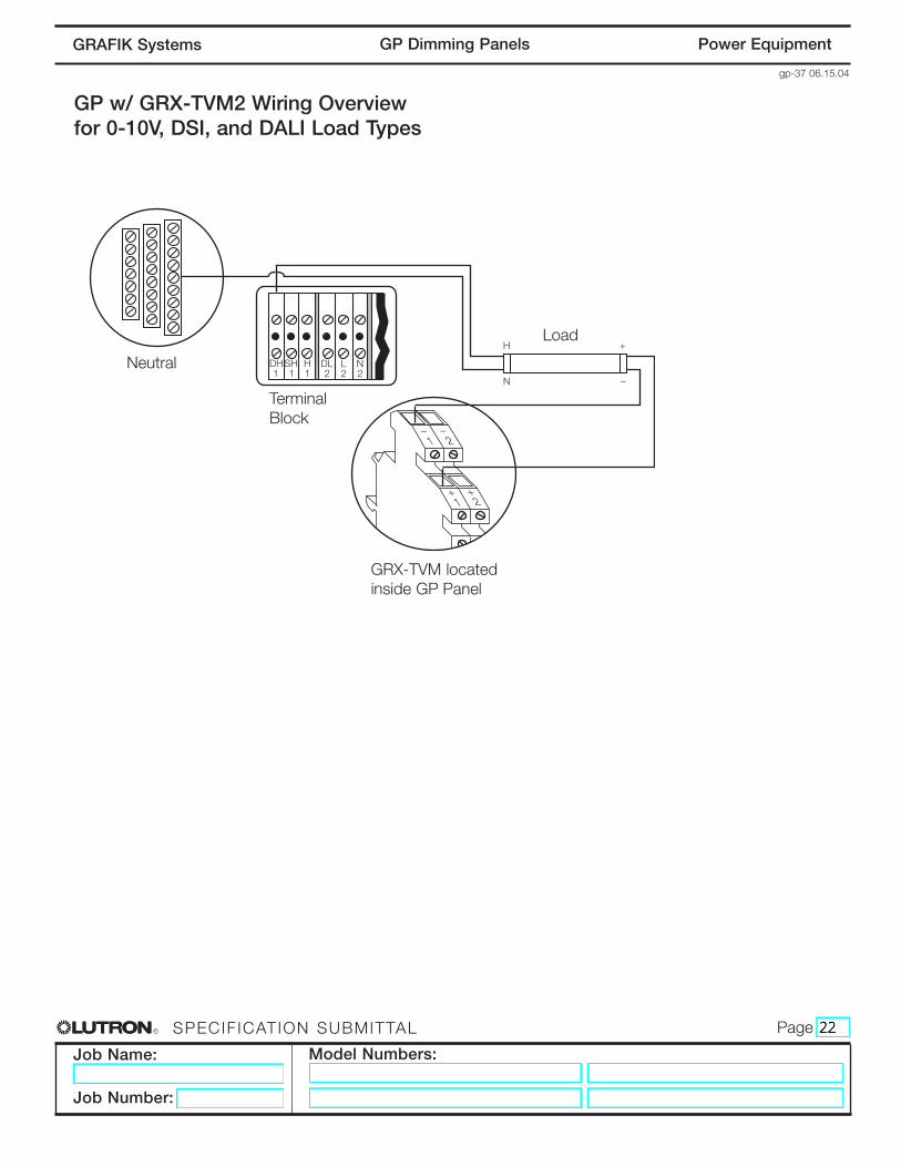
GP w/ GRX-TVM2 Wiring Overviewfor 0-10V, DSI, and DALI Load Types
H
N
+
–
DH1
SH1
H1
L2
N2
DL2
1
+
_
1
2
+
_
2
Neutral
GRX-TVM locatedinside GP Panel
Load
TerminalBlock

R
Job Name:
Job Number:
Model Numbers:
PageSPECIF ICATION SUBMITTAL
gp-40 06.15.04
Power EquipmentGP Dimming PanelsGRAFIK Systems
Control UnitControl Interface
Dimming Panel
Wallstations
Control UnitControl Interface
Power Panel Link
Dimming PanelProcessor Panel
Wallstations
GRAFIK Eye® 4000 System
Class 2 (PELV) wiring link requires:Two #12 AWG (2.5mm2) conductors for control power.One twisted, shielded pair of #18 AWG (1.0mm2) for data link.One #18 AWG (1.0mm2) conductor for Emergency (Essential) sense line, from panel to panel.
Total length of Control Link may be no more than 2,000 ft. (610m).Approved low-voltage cable is available from Lutron,1 Belden, and Liberty. These are approved with#22 AWG data link wires.
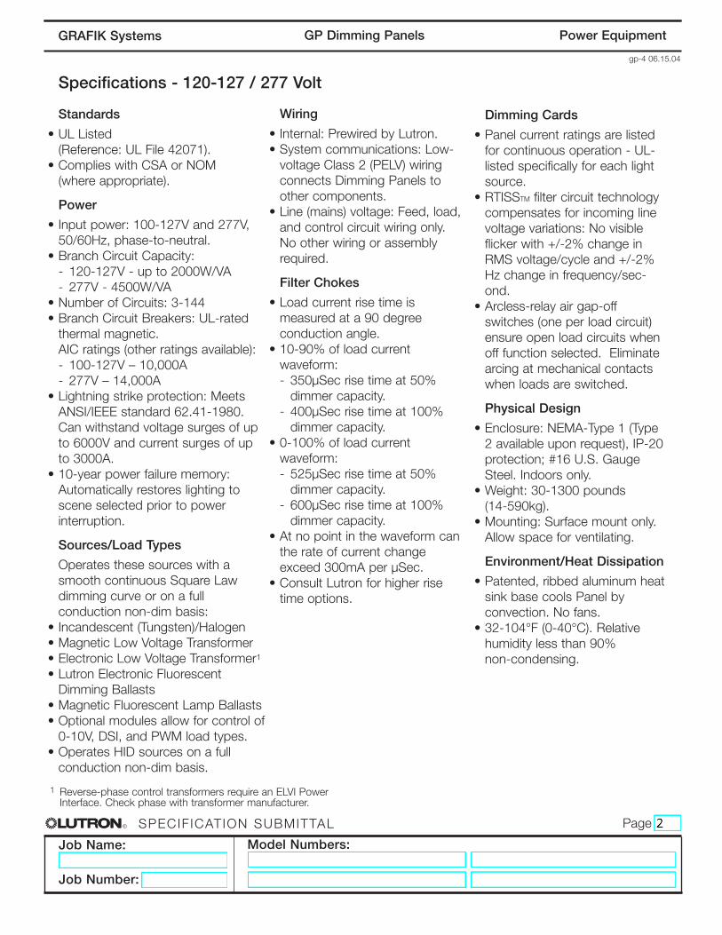
Low-Voltage Class 2 (PELV) Wiring (All Models)
GRAFIK 5000TM/6000®/7000® System
Class 2 (PELV) wiring link requires:Two #12 AWG (2.5mm2) conductors for control power.One twisted, shielded pair of #18 AWG (1.0mm2) for data link.One #18 AWG (1.0mm2) conductor for emergency (essential) sense line, from panel to panel.
Total length of Control Link may be no more than 2,000 ft. (600m).If MUX-RPTR interface and GRX-CBL-46L cable1 is used, length may be up to 4,000 ft. (1200m).
System communications use low-voltage Class 2 wiring. Wiring must be daisy-chained.Wiring must run separately from line (mains) voltage.
GRX-CBL-46L Class 2 (PELV) wiring cable is available from Lutron and contains:Two #12 AWG (2.5mm2) conductors for control power.One twisted, shielded pair of #22 AWG (0.625mm2) for data link.One #18 AWG (1.0mm2) conductor for emergency (essential) sense line.
1
Refer to GRAFIK 5000/6000/7000 Specification

R
Job Name:
Job Number:
Model Numbers:
PageSPECIF ICATION SUBMITTAL
gp-41 06.15.04
Power EquipmentGP Dimming PanelsGRAFIK Systems
SELECT CIRCUIT
Data A OK Power Data B OK
1 2 3 4 D 5
1 2 3 4 D 5 C D
Com
mon
Com
mon
+24
VFW
Sen
se
MU
X
MU
X
Dra
in
Dra
in
MU
X
MU
X
Circuit
1
2
Link
ALink
B
1
2
3,4
5
1
2
3,4
SELECT CIRCUIT
Data A OK Power Data B OK
1 2 3 4 D 5
1 2 3 4 D 5 C D
Com
mon
Com
mon
+24
VFW
Sen
se
MU
X
MU
X
Dra
in
Dra
in
MU
X
MU
X
Circuit
1
2
Link
ALink
B
Class 2 (PELV) Panel-to-Panel Wiring (All Models)
ControlWiring(2) #12 AWG(2.5 mm2)1: Common2: 24VFW
To additionalPower Panels
Dimming Panel 1 Dimming Panel 2
To LightingControls orProcessors
Shield/Drain
(1) #18 AWG(1.0 mm2)5: Sense Line
Data Link(1) shielded, twisted pair #18AWG(1.0 mm2)3: MUX4: MUX
A OK Power
1 2 3 4 5D
24V
FWM
UX
MU
X
Dra
inS
ense
1 2 3 4 D 5 B Dra
in
MU
X
MU
X
C DA
(4) #12 AWG (2.5 mm2)Notes:
• Emergency Power: The additional #18 AWG (1.0mm2)wire is a “sense” line from terminal 5 of another Panel.This sense line allows an Emergency (Essential)Lighting Panel to “sense” when Normal (Non-Essential)power is lost. If more than one Emergency LightingPanel needs to sense from a specific Normal Panel, adedicated wire between each pair of Normal (Non-Essential) and Emergency (Essential) panels may berequired.
• Shield/Drain: Connect shielding as shown. Do notconnect to Ground (Earth) or circuit board of CircuitSelector. Connect the bare drain wires and cut off theoutside shield.
Class 2 (PELV) Terminal Connections
Each low-voltage Class 2 (PELV) terminal can acceptonly two #18 AWG (1.0mm2) wires. Two #12 AWG(2.5mm2) conductors will not fit. Connect as shownusing appropriate wire connectors.

R
Job Name:
Job Number:
Model Numbers:
PageSPECIF ICATION SUBMITTAL
gp-42 06.15.04
Power EquipmentGP Dimming PanelsGRAFIK Systems
Tridonic is a registered trademark of Zumtobel AG.
Option
CustomMainBreaker
Double LugSet
BranchCircuitProtection
LutronTen VoltModule(TVM)
MRI
LockingCover
2LinkTM
Description
Panel features a custom main breaker size.
Panel accepts up to 225A feed.
Branch Circuit Breakers with higher AIC ratings or specialbreaker types such as:• GFI (Ground Fault Interrupt)
Allows panel to operate fluorescent ballasts that meetIEC 929 standards for 0-10V control including:• Lutron’s TVE ballasts• 0-10V neon• PWM fluorescent• Tridonic® DSI (Digital Serial Interface). The TVM can sink or source 5OmA (typically 25-50 ballasts)on each circuit.
Panel dims DC (direct current) lighting in MagneticResonance Imaging (MRI) facilities.
Prevents accidental switching of circuit breakers. Adds anadditional 2.25”(57.2mm) to the front of panel. Available forGP8-GP24 only
• Allows a DMX512 theatrical console to operate the loadcircuits in the dimming panel.
• Allows a GRAFIK Eye 4000 System to handle 128 zones(two links of 64 zones).
• Allows two GRAFIK Eye 4000 Systems to share the samedimming panel.
Application
Jobs with special load requirements.
A single feed with multiple GPDimming Panels is required.
Jobs with fluorescent ballasts thatrequire 0-10V, PWM, or DSI control.
MRI facilities or sound studioswhere standard lighting controlequipment won’t work because ofRFI and EMI.
Service corridors and public areas.
• Control of architectural lightingfrom a DMX512 theatrical consoleis required.
• A mix of architectural andtheatrical lighting exists on the job.
• Multiple systems where space forpanels is limited.