GP-270 Series User Manual - Pro-face America HMI Store
88
i GP-270 Series User's Manual 1) It is forbidden to copy the contents of this manual, in whole or in part, except for the user's personal use, without expressed permission from Digital Electronics Corporation of Japan 2) The information provided in this manual is subject to change without notice. 3) This manual has been written with care and attention to detail; however, should you find any errors or omissions, please contact Digital Elec- tronics and inform them of your findings. 4) Please be aware that we are not responsible for any damages resulting from the use of our products, regardless of article 3 above. All company/manufacturer names used in this manual are the registered trademarks of their respective companies. © Copyright March 1996, Digital Electronics Corporation Preface Thank you for purchasing Digital’s Pro-face GP-270 Series of Graphic Control Panels (hereafter referred to as the GP unit). This GP unit, with its advanced user functions and improved performance, is an upgrade from the earlier GP-250 Series. Please read this manual carefully as it explains, step by step, how to install and use the GP correctly. In its examples, this manual uses the Mitsubishi MELSEC-AnA Series of PLC's wherever possible, connected in a one-to-one relationship with the GP. GP-270 Series refers to the following GP model numbers: GP270-LG11, GP270-SC11(Standard item) GP270-LG21, GP270-SC21(CE marked units) GP270-LG31, GP270-SC31(UL/cUL(CSA) marked units) <Note>
Transcript of GP-270 Series User Manual - Pro-face America HMI Store

iGP-270 Series User's Manual
Preface
1234567890123456789012345678901212345678901234567890123456789012123456789012345123456789012345678901234567890121234567890123456789012345678901212345678901234512345678901234567890123456789012123456789012345678901234567890121234567890123451234567890123456789012345678901212345678901234567890123456789012123456789012345
1) It is forbidden to copy the contents of this manual, in whole or in part,except for the user's personal use, without expressed permission fromDigital Electronics Corporation of Japan
2) The information provided in this manual is subject to change withoutnotice.
3) This manual has been written with care and attention to detail; however,should you find any errors or omissions, please contact Digital Elec-tronics and inform them of your findings.
4) Please be aware that we are not responsible for any damages resultingfrom the use of our products, regardless of article 3 above.
All company/manufacturer names used in this manual are the registeredtrademarks of their respective companies.
© Copyright March 1996, Digital Electronics Corporation
Preface
Thank you for purchasing Digital’s Pro-face GP-270 Series of Graphic ControlPanels (hereafter referred to as the GP unit).This GP unit, with its advanced user functions and improved performance, is anupgrade from the earlier GP-250 Series.Please read this manual carefully as it explains, step by step, how to install and usethe GP correctly.In its examples, this manual uses the Mitsubishi MELSEC-AnA Series of PLC'swherever possible, connected in a one-to-one relationship with the GP.
GP-270 Series refers to the following GP model numbers:GP270-LG11, GP270-SC11(Standard item)GP270-LG21, GP270-SC21(CE marked units)GP270-LG31, GP270-SC31(UL/cUL(CSA) marked units)
<Note>

ii GP-270 Series User's Manual
Preface
Table of ContentsPREFACE
Table of Contents ...................................................................................................... iiEssential Safety Precautions ................................................................................... vUL/cUL (CSA) Application Notes ....................................................................... viiCE Marking Notes ................................................................................................. viiiWhat is IP65f? ....................................................................................................... viiiPackage Contents .................................................................................................... ixSeparately Sold Manual ......................................................................................... ixDocumentation Conventions ................................................................................... x
CHAPTER 1 - INTRODUCTION
1.1 Before Operating GP ................................................................................. 1-11.2 System Structure ........................................................................................ 1-21.3 Optional Equipment .................................................................................. 1-5
CHAPTER 2 - SPECIFICATIONS
2.1 General Specifications ............................................................................... 2-11. Electrical Specifications ................................................................ 2-12. Environmental Specifications ....................................................... 2-1
2.2 Function and Performance ....................................................................... 2-21. Display Functions .......................................................................... 2-23. Structural Specifications ............................................................... 2-22. Screen Memory .............................................................................. 2-33. Touch Panel / Clock Accuracy ...................................................... 2-34. External Interface........................................................................... 2-3
2.3 Interface Specifications ............................................................................. 2-41. Serial Interface ............................................................................... 2-4
2.4 Names and Functions of GP Parts........................................................... 2-52.5 Graphic Panel Dimensions ....................................................................... 2-6
1. GP-270 External Dimensions ....................................................... 2-62. Installation Brackets ...................................................................... 2-73. GP Installation Dimensions .......................................................... 2-8
CHAPTER 3 - INSTALLATION AND WIRING
3.1 Installation .................................................................................................. 3-11. Installation ...................................................................................... 3-1
iiiGP-270 Series User's Manual
Preface
CHAPTER 4 - OFF-LINE MODE
4.1 Entering Off-line Mode ............................................................................. 4-11. When Turning the Unit On ........................................................... 4-12. Enter From Force Reset ................................................................. 4-2
4.2 Main Menu .................................................................................................. 4-34.3 INITIALIZE—Standard Operations ..................................................... 4-44.4 SELF-DIAGNOSIS—Standard Operations .......................................... 4-54.5 Transfer Screen Data ................................................................................. 4-7
CHAPTER 5 - INITIALIZE
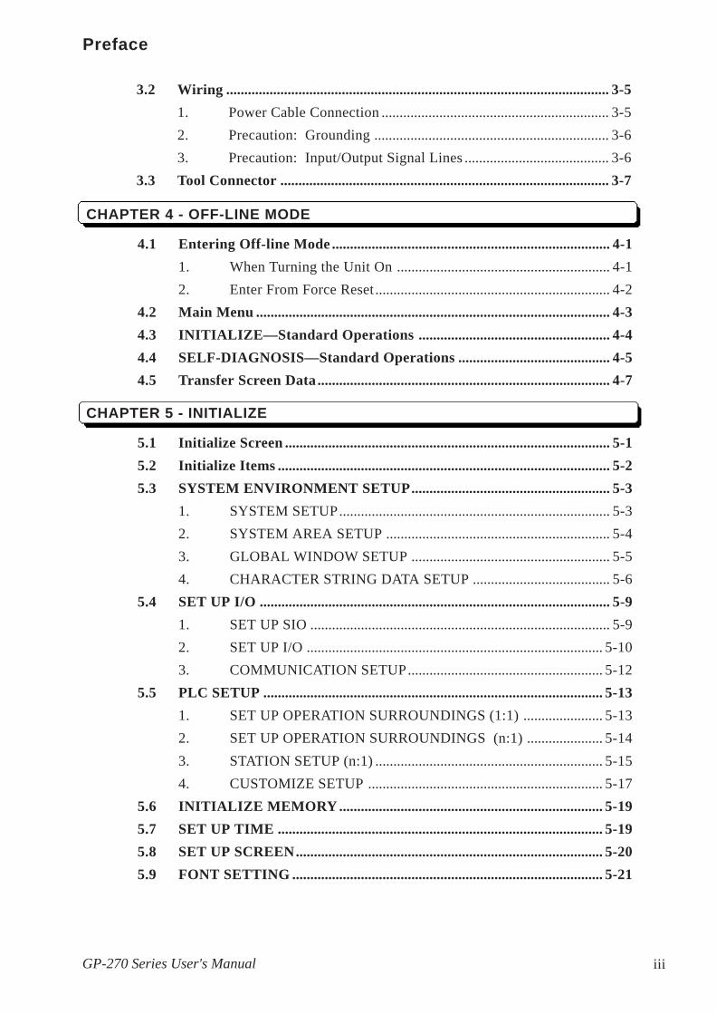
5.1 Initialize Screen .......................................................................................... 5-15.2 Initialize Items ............................................................................................ 5-25.3 SYSTEM ENVIRONMENT SETUP....................................................... 5-3
1. SYSTEM SETUP........................................................................... 5-32. SYSTEM AREA SETUP .............................................................. 5-43. GLOBAL WINDOW SETUP ....................................................... 5-54. CHARACTER STRING DATA SETUP ...................................... 5-6
5.4 SET UP I/O ................................................................................................. 5-91. SET UP SIO ................................................................................... 5-92. SET UP I/O .................................................................................. 5-103. COMMUNICATION SETUP...................................................... 5-12
5.5 PLC SETUP .............................................................................................. 5-131. SET UP OPERATION SURROUNDINGS (1:1) ...................... 5-132. SET UP OPERATION SURROUNDINGS (n:1) ..................... 5-143. STATION SETUP (n:1) ............................................................... 5-154. CUSTOMIZE SETUP ................................................................. 5-17
5.6 INITIALIZE MEMORY ......................................................................... 5-195.7 SET UP TIME .......................................................................................... 5-195.8 SET UP SCREEN..................................................................................... 5-205.9 FONT SETTING ...................................................................................... 5-21
3.2 Wiring .......................................................................................................... 3-51. Power Cable Connection ............................................................... 3-52. Precaution: Grounding ................................................................. 3-63. Precaution: Input/Output Signal Lines ........................................ 3-6
3.3 Tool Connector ........................................................................................... 3-7

iv GP-270 Series User's Manual
Preface
CHAPTER 6 - RUN AND ERRORS
6.1 RUN .............................................................................................................. 6-11. Powering Up................................................................................... 6-12. Off-line Mode ................................................................................ 6-1
6.3 SELF-DIAGNOSIS .................................................................................. 6-101. SELF-DIAGNOSIS Item List ..................................................... 6-102. SELF-DIAGNOSIS—Details Of Each Item .............................. 6-11
6.4 Error Message .......................................................................................... 6-141. Error Message List ....................................................................... 6-142. Error Messages—Details ............................................................. 6-15
CHAPTER 7 - MAINTENANCE
7.1 Regular Cleaning ....................................................................................... 7-17.2 Periodic Check-Up ..................................................................................... 7-27.3 Changing the Backlight ............................................................................ 7-3
INDEX
6.2 Troubleshooting .......................................................................................... 6-21. Troubles .......................................................................................... 6-22. No Display...................................................................................... 6-43. Would Not Communicate .............................................................. 6-74. The Touch Panel Does Not Work ................................................. 6-9

vGP-270 Series User's Manual
Preface
This manual includes procedures that must be followed to operate the GP correctlyand safely. Be sure to read this manual and any related materials thoroughly tounderstand the correct operation and functions of this unit. Icon MeaningTo allow you to use the GP correctly, throughout this manual, the following iconsare provided next to operations requiring special attention. The operations de-scribed with these icons contain essential safety information. The following is anexample of these icons and their meanings:
Indicates situations where severe bodilyinjury, death or major equipment damagecan occur.
Indicates situations where slight bodilyinjury or machine damage can occur.Caution
Warning
Essential Safety Precautions
WARNINGS
• Confirm that the GP's Power Cord is not plugged in to themain power when connecting the GP's power terminals.
• Whenever changing the Backlight, to prevent electricshocks or burns, be sure to unplug the GP's powercordand use protective gloves.
• The GP contains high voltage parts and electric shockscan occur when disassembling the unit. Do not disas-semble the GP.
• Do not use power beyond the GP's specified voltage range.If you do, it may cause a fire or an electric shock.
• Do not use the GP in an environment where flammablegas is present. It may cause explosion.
• Do not use touch panel keys in life-related or importantdisaster prevention situations. Use separate hardwareswitches for such keys.
• Please design your system so that the machine will notmalfunction by a communication fault between the GPand its host controller. If not, there could be a danger ofinjuring a person or damaging materials.

vi GP-270 Series User's Manual
Preface
CAUTIONS• The GP uses a lithium battery for backing up its internal
clock data. If the battery is incorrectly replaced, it mayexplode. To avoid this danger, please consult with yourlocal GP distributorwhen the battery needs replacement.
• Do not strike the GP's touch panel with a hard or heavyobject, or press on the touch panel too strongly since itmay damage the display.
• Do not install the GP where the temperature will exceedits specified range.
• Be sure that water, liquids or metal particles do not enter theGP, since it may cause a malfunction or a short circuit.
• Do not store or use the GP where powerful shocks orvibration are likely to occur.
• Do not store or use the GP where chemicals and acidsare present in the air.
• Do not use paint thinner or organic solvents to clean theplastic case or display panel.
• Be sure to back up your GP's screen data regulary.
Concerning the GP's Display• The following LCD characteristics are normal and are not evidence
of a defect.1) Contouring, i.e. when some parts of the screen are brighter
than others, may occur, creating a wavelike pattern.2) Minute grid-points (dark/ light).3) Shadows (At the top of the LCD).4) Display colors appear to have changed.
• Preventing Afterimages: Set the unit to "Stand-by Mode", which will turn theGP's display OFF after a period of non-use.
Do not display any single screen for an extended pe-riod of time. Change the screen display periodically.

viiGP-270 Series User's Manual
Preface
The GP270-LG31-24V and GP270-SC31-24V are cUL 1950 (+ D3) recognizedproducts. Please pay special attention to the following instructions when applyingfor UL approval for machinery which includes one of these GP units.• GP conforms as a component for the following standards:UL 1950 (+ D3), Second Edition, dated February 26, 1993 (Standard for Safety ofInformation Technology Equipment, including Electrical Business Equipment)CAN/CSA-C22.2 No. 950-M89 (+D3) (Standard for Safety of InformationTechnology Equipment, including Electrical Business Equipment)The D3 deviations are: SC1.3.4, SC1.3.8, SC2.1, SC2.9, and SC5.3.These deviations will lose effect on March 15, 2000.
GP270-LG31-24V (UL Registration Model: 0680028-03) Class III EquipmentGP270-SC31-24V (UL Registration Model: 0680028-04) Class III Equipment
• Machinery with a GP mounted in it requires UL inspection for the combinationof the GP and the machinery.
• GP mounted machinery will also be treated as having the D3 deviations.• Please be sure the GP's rear cover is protected by machinery with a FIRE
ENCLOSURE. The GP's rear plastic case does not have the features for aflame protective enclosure required by the UL standard. The FLAMMABIL-ITY RATING for the rear plastic case is 94V-0.
• The electric power must be supplied by ELV circuit that complies with Sub-clause 1.3.8 in the UL1950 Standard, or from a limited power source whichfulfills conditions C1 and 2.11.
1. A power supply with DOUBLE INSULATION or REINFORCED secondarycircuits (for the UL recognized power supply (QQGQ2), the Output Category(OC) must be SELV). However, for a power supply with Spacing (SP) ap-proved by the UL 1950, use a supply approve without the D3 deviations.
2. With any load and a combination of single failure, the power supply must havepower output under 250VA, and output current under 41A.
3. The electric power must be supplied through a UL approved fuse (JDYX) .However, the fuse must be rated 1A, and it must break when the current ex-ceeds 210% of the rating for over 120 seconds.
• If the GP is mounted to cool itself naturally, please mount it onto a verticalpanel. Also, ensure that GP unit is mounted at least 100mm away from adja-cent structures and other parts. If these conditions are not met, the heat generated by internal components may cause a failure to meet the UL standardrequirements.
UL/cUL Application Notes

viii GP-270 Series User's Manual
Preface
The GP270-LG21-24VP and GP270-SC21-24VP models are CE marked productsthat conform to EMC Directive, EN55022 Class A and EN50082-2.
CE Marking Notes
This unit's protection rating of IP65f is actually a composite code, consisting of theinternationally recognized British "Ingress Protection" standard (BS EN60529:1992) - "IP65", and the standard developed by the Japanese ElectronicsManufacturer's Association (JEM) - "f". This code is used in this manual to iden-tify a given product's degree of structural resistance to a variety of environmentalelements and thus, prevent problems or accidents related to the inappropriate useof a product.The individual meaning of each character of this code is explained below. Thiscode indicates the degree of ingress protection provided from the front face of theGP, and assumes that the GP is securely mounted into a metal panel.
IP 6 5 f(1) (2) (3) (4)
(1) Designates the type of protection provided.(2) Indicates the degree of protection provided to the human body by the unit, and
the degree of protection provided by the unit's front face from particles/dustintrusion into the interior of the unit.Here, "6" indicates that the unit is completely protected from dust intrusion.
(3) Indicates the degree of protection provided by the unit's front face from waterintrusion into the interior of the unit.Here, "5" indicates that the unit is protected from water intrusion from a directwater jet.
(4) Indicates the degree of protection provided by the unit's front face from oilparticle intrusion into the interior of the unit.Here, "f" indicates that the unit is completely protected from oil intrusion viaeither oil particles or oil splashes from any direction (to the front panel).
What is IP65f?

ixGP-270 Series User's Manual
Preface
The GP's packing box contains the items listed below. Please check to confirmthat all items shown below have been included.
Installation Fasteners (**/set)
Installation Guide (1)
This unit has been carefully packed, with special attention to quality. However,should you find anything damaged or missing, please contact your local GPdistributor immediately for prompt service.
GP Unit (GP270-LG11, GP270-SC11,GP270-LG21-24VP, GP270-SC21-24VP,GP2710-LG31-24V,GP270-SC31-24V)
This manual (GP-270 Series Users Manual) is sold separately.
GP-270 Series Users Manual
GP-270 SeriesUsers Manual
Package Contents
Separately Sold Manual
InstallationGuide
GP-270
Series Unit

x GP-270 Series User's Manual
Preface
The list below describes the documentation conventions used in this manual.
Documentation Conventions
Warns a situation that could seriously injure a person or lead to
death if the GP is used in a wrong way or the warning is ignored.
Explains a situation that could injure a person ir damage materialsif the GP is used in a wrong way, or the warning is ignored.
Explains a situation that requires a moderate amount of caution.
PLC Programmable Logic Controller*1 A reference point. Describes the word or phrase marked by the
asterisk (*) and the corresponding number.
Indicates a word or phrase that may require additional explana-tion.
Reference pages on related topics.
n:1 n:1 (multi-link) connection setup.

GP-270 Series User's Manual 1-1
Introduction
Chapter 1
Introduction1. Before Operating GP2. System Structure3. Optional Equipment
1.1 Before Operating GP
Follow these steps before operating the GP unit.
1 Preparation Before using the GP, arrange the hardware andcheck the specifications, wiring, and installation.
Chapter 2, "Specifications", and Chap-ter 3, "Installation and Wiring".
2 Screen Design Draw a Screen and design a Tag layout, using theScreen layout sheet and Tag list provided in yourmanual.
3 Select PLC Using your screen design software, select the PLChost that is connected to the GP unit.
Software Operation Manual.
4 Create Screen/ Run Screen SetupSetup the screen and tags in your screen editingsoftware, while referring to your screen design.
Software Operation Manual and TagReference Manual.
5 Screen Data Transfer Transfer the data from the Screen design softwareon your PC to the GP unit using the DownloadingCable (included w/ the screen design software).
Software Operation Manual.
6 Initialize Following the specifications of the PLC host inuse, initialize the setup of the GP unit.

GP-270 Series User's Manual1-2
Introduction
Chapter 4, "Initialize", and the PLCConnection Manual.
7 Run Link the GP with the PLC host using the Connec-tion Cable (different cables may be necessary fordifferent hosts), then run the System.
PLC Connection Manual.
1.2 System Structure
The diagram on the following page illustrates the peripheral equipment of theGP unit.
Legend
GP Interface PLC Interface PC InterfaceTool Connector RS-232C Port Printer InterfaceSerial Interface RS-422 Port
Program Port Screen Editing Environment GP Operating Environment
Optional Parts
Optional items sold separately.
Maintenance Parts
These items are originally included with or in the packageof GP unit. They can also be purchased separately for replacement.

GP-270 Series User's Manual 1-3
Introduction
RS-232C Cable *2
GP410-IS00-0
Memory LoaderGP070-MU01-0
Bar Code Reader(recommended *1 )
RS-422 ConnectorTerminal Exchange AdapterGP070-CN10-0 Host Controller
e.g. PLC
GP-PRO/PB3 GPPRO3-PB01M-V*IBM Compatible PCDownloading Cable
(included in software package)
RS-422 CableGP230-IS11-0GP230-IS12-0 (Multi-link cable)
Mitsubishi PLC A-Series 2 Port Adapter
GP030-MD11-0
Siemens Simatic S5 SeriesProgram Port I/F Cable
GP000-IS11-0
Mitsubishi PLC A-SeriesProgram Port I/F Cable
GP430-IP10-0
Mitsubishi PLC FX-SeriesProgram Port I/F Cable
GP430-IP11-0
GP UnitGP270-LG11 GP270-LG21-24VP GP270-LG31-24VGP270-SC11 GP270-SC21-24VP GP270-SC31-24V
Printer(EPSON ESC/P24-84
or equivalent)

GP-270 Series User's Manual1-4
Introduction
Maintenance Items
*1 Usable PC model may be limited.Software Operation Manual.
*2
*3 According to the PLC type, some connections cannot be made.PLC Connection Manual.
AimexCorporation
BR-331 PC2(Pen type)
ReadingWidth
Touch ScannerType
KeyboardConnection Type
ReadingWidth
Touch ScannerType
60mm OPT-1125-WL 98 OPT-1125-WD 98 65mm TCD-5510M80mm OPT-5125-WL 98 OPT-5125-WD 98 82mm TCD-5510L
100mm LT-2125-WL 98 LT-2125-WD 98 105mm TCD-5510W
TohkenOPT Electronics
Optional Item
Cover SheetGP270-COVER-20P
GP-270 Backlight BulbsGP270-BL00-MS
GP-70 Series Installation BracketsGP070-AT00-MS
Rubber GasketGP270-WP10-MS

GP-270 Series User's Manual 1-5
Introduction
ITEM DESCRIPTION
ScreenEditingTool
GP-PRO/PB IIIGP screen editingsoftware(GPPRO3-PB01M-V*)
GP-PRO/PB IIIPC based Screen design Software to run onGP-470/570/270 Series.Downloading Cable Connects your PC to the GP andtransfers screen data between the two.
SerialInterface
RS-232C Cable(GP410-IS00-O)
I/F Cable to connect the GP unit with the PLC.
RS-422 Cable(GP230-IS11-O)
Multi-link Cable(GP230-IS12-O)
Runs multi-link (n:1) SIO between each PLC typeand GP series. RS-422 interface cable.
RS-422 TerminalConnector Adapter(GP070-CN10-O)
Adapter for changing the terminal output from a seriainterface to RS-422 I/F.
Siemens Simatic SeriesProgramming Port I/FConnection Cable(GP000-IS11-O)
TTY converter cable for Siemens Simatic S5 SeriesPLCs. You would not be able to use a programconsole at the same time.
Mitsubishi A SeriesProgramming Port I/Fcable(GP430-IP10-O)
Connects directly to Mitsubishi's FX Series I/FProgramming Console, making the conversion link uunnecessary. However, cannot use a programconsole at the same time.
Mitsubishi PLC FXSeries ProgrammingPort I/F Cable(GP430-IP11-O)
Mitsubishi PLC ASeries 2 Port Adapter(GP030-MD11-O)
An interface unit that enables use of the GP Seriesand Mitsubishi A series equipment in the samelocation.
*1 According to your PLC type, some connections are not possible. PLC Con-nection Manual.
*1
1.3 Optional Equipment
All optional equipment listed below are products of Digital Electronics Corp.

GP-270 Series User's Manual1-6
Introduction
ITEM DESCRIPTIONOptionPart
Cover SheetGP-270(GP270-COVER-20P)
Disposable GP screen protection from dust and otherelements. The GP can be used with the Cover Sheetstill attached to the GP screen. (20/set)
Mainte-nanceParts
GP-270 Backlight Bulbs(GP270-BL00-MS)
Replacement Backlight bulbs.
GP-70 SeriesInstallation Brackets(GP070-AT00-MS)
Metal installation brackets for GP-470/570/270 Series
Rubber GasketGP-270 Series(GP270-WP00-MS)
Rubber gasket for installing the GP. Same as in theoriginal GP equipment package.
ToolConnector
Memory Loader(GP070-MU01-O)
Runs a high speed data copy from one GP to another(System program and Screen data).
(GP270-WP10-MS)

GP-270 Series User's Manual 2-1
GP270-LG** GP270-SC**Input Voltage DC24V
Rated Voltage DC20.4V to DC27.6V
Power Consumption 12W or less
Allowable Voltage Drop 2ms or less
Voltage Endurance AC1000V 10mA for 1 minute(between charging and FG terminals)
Insulation Resistance 20MΩ or higher at DC500V(between charging and FG terminals)
Ratings(For front face of installed unit)
Equivalent to IP65f (JEM1030) and NEMA #250 TYPE 4X/12
External Dimensions(mm)
172mm (W) x 127mm (H) x 58mm (D)(main unit only)
Weight 800g or less(GP unit only )
Cooling Method Natural air circulation
*1 See note on following page.
Chapter 2
Specifications1. General Specifications 4. Names and Functions of GP Parts2. Function and Performance 5. Graphic Panel Dimensions3. Inter face Specifications
2. Structural Specifications
2.1 General Specifications
1. Electrical Specifications

Specifications
GP-270 Series User's Manual2-2
*1 The front face of the GP unit, installed in a solid panel, has been tested using conditionsequivalent to the standard shown in the specification . Even though the GP unit’s level ofresistance is equivalent to the standard, oils that should have no effect on the GP canpossibly harm the unit. This can occur in areas where either vaporized oils are present, orwhere low viscosity cutting oils are allowed to adhere to the unit for long periods of time. Ifthe GP’s front face protection sheet becomes peeled off, these conditions can lead to theingress of oil into the GP and separate protection measures are suggested. Also, if non-approved oils are present, it may cause deformation or corrosion of the front panel’s plasticcover. Therefore, prior to installing the GP be sure to confirm the type of conditions thatwill be present in the GP’s operating environment.If the installation gasket is used for a long period of time, or if the unit and its gasket areremoved from the panel, the original level of the protection cannot be guaranteed. Tomaintain the original protection level, you need to replace the installation gasket regularly.
3. Environmental Specifications
*1 Be sure to use your country's applicable standard.
Ambient OperatingTemperature 0oC to 50oC
Storage Temperature -20oC to 60oC
Ambient Humidity 20%RH to 85%RH
Atmosophere Free of conductive dust and corrosive gasses
Vibration Resistance 10Hz to 25Hz (2G in X, Y, Z directions for 30min.)
Noise Voltage: 1000Vp-pPulse Duration: 1msec.
Arise Time: 1nsGrounding 100Ω or less grounding resistance*1
Noise Immunity(via noise simulator)
(From previous page)

Specifications
GP-270 Series User's Manual 2-3
GP270-LG** GP270-SC**Display Media Monochrome LCD STN Color LCD
Display Color White, Black 8 colors (white, red, blue,green, yellow, magenta, cyan,black) Tiling patterns make
blends of colors possible
Back light CFL (under normal temperatures and humidity, lifespan =20,000 hours)
Resolution 320 × 240 pixels
Display Area 96W × 72H (mm)
Attributes Blink/ Reverse Video
ContrastAdjustment
The Touch Panel has 8 levels of contrast adjustmentsavailable
Characters Korean: (KSC5601-1992 codes) Hangul fonts (including Kanji)
Chinese: (GB2321-80 codes) simplified Chines fonts
Taiwanese: (Big 5 codes) traditional Chinese fonts
ASCII: (Code Page850) Alphanumeric (including European fonts)
Japan: ANK 158 type, Kanji:6349 (includes non-Kanji:453, andStandard JIS Type 1 and Type 2)
Char. Disp. #8x8 dot font: 40 Char. per row, 30 rows8x16 dot font: 40 Char. per row, 15 rows16x16 dot font: 20 Char. per row, 15 rows
Character Size Height and width can be expanded by 2, 4, or 8.
2.2 Function and Performance
1. Display Functions
Specifications
GP-270 Series User's Manual2-4
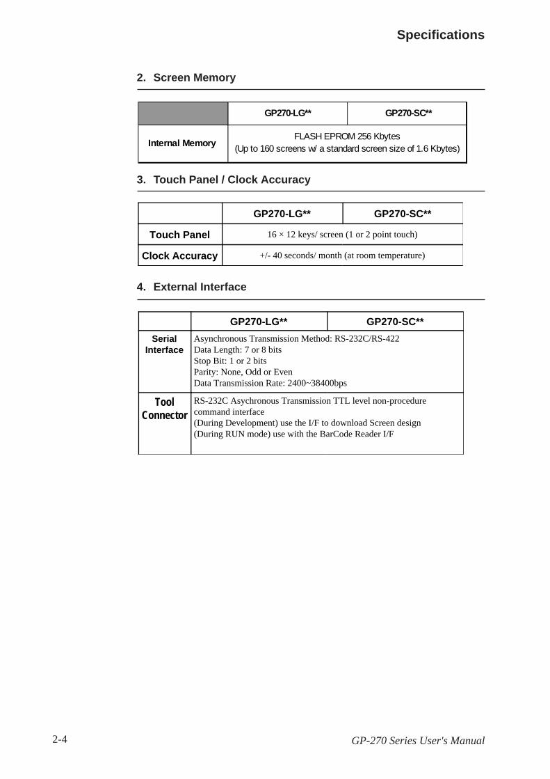
2. Screen Memory
3. Touch Panel / Clock Accuracy
GP270-LG** GP270-SC**
Touch Panel 16 × 12 keys/ screen (1 or 2 point touch)
Clock Accuracy +/- 40 seconds/ month (at room temperature)
4. External Interface
GP270-LG** GP270-SC**Serial
InterfaceAsynchronous Transmission Method: RS-232C/RS-422Data Length: 7 or 8 bitsStop Bit: 1 or 2 bitsParity: None, Odd or EvenData Transmission Rate: 2400~38400bps
ToolConnector
RS-232C Asychronous Transmission TTL level non-procedurecommand interface(During Development) use the I/F to download Screen design(During RUN mode) use with the BarCode Reader I/F
GP270-LG** GP270-SC**
FLASH EPROM 256 Kbytes(Up to 160 screens w/ a standard screen size of 1.6 Kbytes)Internal Memory

Specifications
GP-270 Series User's Manual 2-5
2.3 Interface Specifications
1. Serial Interface
SIO
14
2513
1
Pin#
SignalName
Condition Pin#
SignalName
Condition
1 FG Frame ground 14 VCC 5V output 0.25A
2 SD Send data (RS-232C) 15 SDB Send data B (RS-422)
3 RD Receive data (RS-232C) 16 RDB Receive data B (RS-422)
4 RS Request send (RS-232C) 17 NC No connection
5 CS Clear send (RS-232C) 18 CSB Clear send B (RS-422)
6 NC No connection 19 ERB Enable receive B (RS-422)
7 GND System ground 20 ER Enable receive (RS-232C)
8 CD Carrier detect (RS-232C) 21 CSA Clear send A (RS-422)
9 TRMX Termination (RS-232C) 22 ERA Enable receive A (RS-422)
10 RDA Receive data A (RS-422) 23 RESERVED Reserved for future use
11 SDA Send data A (RS-422) 24 NC No connection
12 NC No connection 25 RESERVED Reserved for future use
13 NC No connection
Recommended Connector: Dsub25pin plug XM2A-2501<made by OMRON Corp.>Recommended Cover : Dsub25pin Cover XM2S-2511<made by OMRON Corp.>
Dsub25pin plug XM2A-2501<made by OMRON Corp.>Recommended Cable : CO-MA-VV-SB5P×28AWG <made by HITACHI Cable Ltd.>
PLC Connection Manual to determine your PLC's connection points.
When creating your own cable, follow the instructions listed belowconcerning each connection type.RS-422The following pairs of pin #'s must be connected to each other........ #18 (CSB) <—> #19 (ERB)....... #21 (CSA) <—> #22 (ERA)• When connecting the RS-422 cable and the #9 (TRMX) and #10(RDA) points, a termination resistance of 100Ω is added between RDAand RDB.• When making a cable for the Memory Link format, be sure to selecta 4-line System.
RS-232C• Do not use the following pins:9 (TRMX), 10 (RDA), 11 (SDA), 15 (SDB), 16 (RDB), 18 (CSB), 19(ERB), 21 (CSA), 22 (ERA).
Be sure to connect your GP's SG/GND (Signal Ground) Terminal tothe other unit's signal ground terminal.
Specifications
GP-270 Series User's Manual2-6
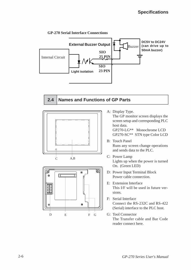
GP-270 Serial Interface Connections
BuzzerSIO25 PIN
DC5V to DC24V(can drive up to50mA buzzer)
SIO23 PIN
2.4 Names and Functions of GP Parts
A,BC
ED F G
A: Display Type.The GP monitor screen displays thescreen setup and corresponding PLChost data.GP270-LG** Monochrome LCDGP270-SC** STN type Color LCD
B: Touch PanelRuns any screen change operationsand sends data to the PLC.
C: Power LampLights up when the power is turnedOn. (Green LED)
D: Power Input Terminal BlockPower cable connection.
E: Extension InterfaceThis I/F will be used in future ver-sions.
F: Serial InterfaceConnect the RS-232C and RS-422(Serial) interface to the PLC host.
G: Tool ConnectorThe Transfer cable and Bar Codereader connect here.
Internal Circuit
External Buzzer Output
Light isolation

Specifications
GP-270 Series User's Manual 2-7
2.5 Graphic Panel Dimensions
1. GP-270 Series External Dimensions
Unit: mm
Top View157.5
Rear View
172 + 1
72
96
127
+ 1
Front View Side View58 + 1
535
112.5

Specifications
GP-270 Series User's Manual2-8
2. Installation Fasteners
Units: mm
Top View
Rear ViewFront View Side View

Specifications
GP-270 Series User's Manual 2-9
less than 4-R3
3. GP Installation Dimensions
Unit: mm
Mounting Hole for Installation
123456789012345678901234567890123456789012345678901234567890123456789012345678901234567890123456789012345678901234567890123456789012345678901234567890123456789012345678901234567890123456789012345678901234567890123456789012345678901234567890123456789012345678901234567890123456789012345678901234567890
+ 0.5- 0158
113+ 0.5- 0

Specifications
GP-270 Series User's Manual2-10
1234567890123456789012345678901212345678901123456789012345678901234567890121234567890112345678901234567890123456789012123456789011234567890123456789012345678901212345678901123456789012345678901234567890121234567890112345678901234567890123456789012123456789011234567890123456789012345678901212345678901123456789012345678901234567890121234567890112345678901234567890123456789012123456789011234567890123456789012345678901212345678901123456789012345678901234567890121234567890112345678901234567890123456789012123456789011234567890123456789012345678901212345678901123456789012345678901234567890121234567890112345678901234567890123456789012123456789011234567890123456789012345678901212345678901
MEMO

Chapter 3
Installation and Wiring1. Installation 3. Printer Connection2. Wiring 4. Tool Connection
3.1 Installation
Creating a Panel Cut OutCreate the correct sized opening required to install the GP, using the installa-tion dimensions given.
2.5.3 “GP Panel Cut Out Dimensions”
The mositure resistant gasket, installation brackets and attachment screwsare all required when installing the GP.
1.6 to 5mm
• It is important that the panel or cabinet's surfaceis flat, in good condition and has no jagged edges.
• Panel thickness should be from 1.6mm to 5.0mm.
Cut OutOpening
Panel
Before installing the GP into a cabinet or panel, check that themoisture resistant gasket is securely attached to the unit.
It is strongly recommended that you use the gasket since itabsorbs vibration in addition to repelling water.Place the GP on a level surface with the display panel facingdownward. Check that the GP’s moisture resistant gasket isseated securely into the gasket’s groove, which runs aroundthe perimeter of the panel’s frame. For details about install-ing the gasket, refer to
7.1.2 Moisture Resistant Gasket Replacement
Moisture resistantgasket
Rear face
When installing the GP panel, be sure to follow the steps listed below.

Installation and Wiring
GP-270 Series User's Manual3-2
• The GP uses ventilation in its outer shell to naturally cool itself. When install-ing the unit horizontally or sideways, use a forced air cooling system (i.e. a fan)or lower the surrounding temperature to avoid overheating.
Vertical Installation
Screen Face
Side View
Horizontal Installation
• For easier maintenance and operation, plus better ventilation, ensure the GPunit is mounted at least 100 mm away from adjacent structures and other parts.
Sideways Installation

Installation and Wiring
GP-270 Series User's Manual 3-3
• When installing sideways, place the GP so that the Power Terminal Blockpoints upwards.
• Ensure heat from other equipment does not cause extra heating pressure onthe GP.
• Do not use GP-270 Series in an environment that exceeds 50o C.
• Ensure that this unit is located as far away as possible from electromagneticcircuits, non-fuse type breakers, and other equipment that can cause arcing.
• When installing the GP unit, with natural air circularion cooling system,onto a slanted panel, the panel slope should not incline more than 30o.
Secure the Installation brackets from the backside of the panel.
There are 4 insertion slots on the top and bottom of the GP, where the metalinstallation brackets hook on.
1)
Top/Bottom View
Install the unit from the front of the panel opening.
Side View
Panel
less than 30o

Installation and Wiring
GP-270 Series User's Manual3-4
2) Installation BracketPanel
Front Side Back Side
InsertionSlot
3) After inserting the brackets into the appropriate slots, carefully force thebracket to the back of the GP.
Use a screw driver and tighten the screw from the back to hold the GP unit inplace. No more than 0.5 to 0.6N•m is required to tighten the screw.
Using too much force may damage the GP unit.

Installation and Wiring
GP-270 Series User's Manual 3-5
1. Power Cable Connection
• To avoid electric shocks, be sure the Power Cord is unplugged from the mainpower outlet before connecting the power terminals to the GP's terminal block.
• GP-270 Series units can only use DC24V input. If you supply power otherthan DC24V, you will damage both the power supply and the GP unit.
• There is no power switch on the GP unit, so please use a breaker switch.
*1 Ring Terminals: V2-S3 equivalent (made by JST)
FGCrimp-on Ring
Terminals *1
—+ +
FG
Power Terminal Block
Connect the GP power cord terminals as follows.
1) Check to make sure the Power is Off.
2) Remove the Terminal Block's protective plastic cover.
3.2 Wiring
When the FG terminal is connected, be sure the wire is grounded. Not groundingthe GP unit will result in excess noise.
• Wherever possible, use thick wires (max 2mm2) for power terminals, andprovide an extra twist to the wire during connection.
• Please use Ring Terminals with the size described below.
• To avoid a short among the ring terminals when the screws get loosen,please use ring terminals with a sleeve.
GP-270 Rear View
under6.0mm
over Ø3.2mm

Installation and Wiring
GP-270 Series User's Manual3-6
2. Precaution: Grounding
3. Precaution: Input/Output Signal Lines
Input and output signal lines must be separated from the power controlcables for operating circuits.
If this is not possible, use a shielded cable and connect the shield to theframe of the GP unit.
Connect the GP's FG terminal to an ex-clusive ground. [diagram (a). Be surethere is a grounding resistance of 100Ωor less, or your country's applicablestandard.
If exclusive grounding is not possible,use a common connection point. [dia-gram (b)]
The grounding wire should have across sectional area greater than2mm2. Set the connection point asclose to the GP unit, and make the wireas short, as possible. When using along grounding wire, replace the thinwire with a thicker wire placed in aduct.
If this equipment does not functionproperly when grounded, disconnectthe ground wire from the FG termi-nal.
(a) Exclusive Grounding (BEST)
otherequipment
GP unit
GP unit otherequipment
GP unit otherequipment
(b) common grounding (OK)
(c) common grounding (BAD)
3) Disconnect the screws from the 3 terminals, align the power wire terminalends and re-attach the screws. (Check each wire to make sure the con-nections is secure)
4) Replace the plastic Terminal Block cover.

Installation and Wiring
GP-270 Series User's Manual 3-7
The Data Transfer Cable or a Bar Code Reader can be connected to the ToolConnector socket.
Side View
• When inserting or removing items from the Tool Connector socket, be surethe GP unit has been turned Off.
• When the Bar Code Reader uses a different power supply: - Turn the Bar Code Reader on before turning the GP unit on. - Turn the GP unit off before turning the Bar Code Reader off.
3.3 Tool Connector
Tool Connector

Installation and Wiring
GP-270 Series User's Manual3-8
12345678901234567890123456789012123456789012123456789012345678901234567890121234567890121234567890123456789012345678901212345678901212345678901234567890123456789012123456789012123456789012345678901234567890121234567890121234567890123456789012345678901212345678901212345678901234567890123456789012123456789012123456789012345678901234567890121234567890121234567890123456789012345678901212345678901212345678901234567890123456789012123456789012123456789012345678901234567890121234567890121234567890123456789012345678901212345678901212345678901234567890123456789012123456789012123456789012345678901234567890121234567890121234567890123456789012345678901212345678901212345678901234567890123456789012123456789012
MEMO

Chapter 4
OFFLINE Mode1. Entering OFFLINE Mode 4. SELF-DIAGNOSIS—Standard Operations2. Main Menu 5. Transfer Screen Data3. INITIALIZE—Standard Operations
4.1 Entering OFFLINE Mode
System Version Current Date/Time
Protocol Name and Protocol Version
The OFFLINE Mode refers to Initialize, Self-Diagnosis, and other setup areascontained in the GP. You will need to switch the GP unit to OFFLINE modebefore viewing any of these areas.
OFFLINE mode is unavailable in a completely new GP until itsSystem Data has been transferred from your PC to the GP, via theGP-PRO/PBIII for Windows software.
To INITIALIZE the setup or run SELF-DIAGNOSIS in the GP unit, you will needto change to OFFLINE mode. There are two ways to switch to OFFLINEmode: first, when turning the unit on, and second, by using Forced Reset.
1. When Turning the Unit On
Press the top left corner of the GP screen within 10 seconds of switching thepower On.

OFFLINE Mode
GP-270 Series User's Manual4-2
2. Enter From Force Reset
From the Force Reset screen, press the OFFLINE button.
For more information about Force Reset Chapter 5.4, "SET UP I/O".
If a Password has been set in INITIALIZE/ SET UP SYSTEM, before enteringthe OFFLINE mode, the following screen displays.
Enter the password, then press Set to enter OFFLINE mode.
For more about the Password, Chapter 5.3, "SYSTEM SETUP".
For more infomation on the password input Chapter 4.3,"INPUTTING NUMBERS ".

OFFLINE Mode
GP-270 Series User's Manual 4-3
The Main Menu includes the setup items listed below: INITIALIZE, SCREENDATA TRANSFER, SELF-DIAGNOSIS, and RUN. Each menu item has differentsetups that must be set to match the corresponding PLC in order for the GPto communicate properly.
Entering the OFFLINE mode displays the screen illustrated below.
Select the menu item by pressing the title on the screen.
A short description of each Main Menu item follows.
INITIALIZEThe setup items listed in this menu are necessary to run the GP unit.
TRANSFER SCREEN DATASelect to transfer screen data to and from the screen editing software.
SELF-DIAGNOSISChecks to see if there are any problems with the GP System or Interface
(I/F).
RUNBegins operations in the GP unit.
For more information about INITIALIZE, refer to Chapter 5, "Ini-tialize"; for more information about TRANSFER SCREEN DATA, refer to theSoftware Operation Manual; for more information about SELF-DIAGNOSISand RUN, refer to Chapter 6, "Run and Errors".
4.2 Main Menu

OFFLINE Mode
GP-270 Series User's Manual4-4
Selecting A Menu• Press the menu title to setup.
• Press the menu item you wish to setup.
Inputting Numbers• After selecting an input field by touching it, use the numeric touch keysthat appear next to enter numeric values.
Selecting Setup Conditions• After selecting the menu item, press the option you would like to setup. Inthis example, pressing the TOUCH BUZZER SOUND turns that option Off.
4.3 INITIALIZE—Standard Operations

OFFLINE Mode
GP-270 Series User's Manual 4-5
Ending SetupTo end setup, you would usually press the top-left button, SET.
If you wish to exit the screen without saving the changes, press the ESCbutton.
Selecting A MenuPress the title of the menu item to diagnose.
Return To Previous ScreenPress the title of the screen you would like to return to.
E.g. To return to the MAIN MENU from the SYSTEM ENVIRONMENT SETUPscreen, simply press the MAIN MENU title.
• Press the SET key to write the Setup con-ditions onto the Internal FEPROM, whichmay take some time, causing a delay inreturning to the previous screen. There-fore, do not touch the screen until the pre-vious menu display returns.
• Press the CANCEL key to not write theSetup conditions onto the InternalFEPROM and return to the previous menu.
4.4 SELF-DIAGNOSIS—Standard Operations

OFFLINE Mode
GP-270 Series User's Manual4-6
SET, ESC KeysAfter selecting the SELF-DIAGNOSIS item, the and keys appear atdifferent times at the top of the screen.
E.g.
• SET KeyWhen this key is pressed, the Self-Diagnosis begins.
• ESC KeyWhen this key is pressed, the Self-Diagnosis command is cancelled, and youreturn to the Self-Diagnosis menu.
After Check—To Return To SELF-DIAGNOSIS MENU
When OK displays, pressingonce anywhere on the displayscreen returns you to the SELF-DIAGNOSIS MENU.
When an Error Message displays
When an error message appearson the display screen, press thebottom two corners of the panel( 1 , 2 ) t o r e t u r n t o t h eSELF-DIAGNOSIS MENU.

OFFLINE Mode
GP-270 Series User's Manual 4-7
Return To Main MenuPress the MAIN tab in the SELF-DIAGNOSIS menu to return to the MAIN MENU.
4.5 Transfer Screen Data
GP-270 Series (side view)
PC (rear view)
Adapter
Data Transfer Cable
Tool ConnectorRS-232C
Port
To transfer screen data from your PC to the GP, connect one end of the DataTransfer Cable to the GP-270 unit's Tool connector, and the other to your PC(Adaptor may be required), as shown below.
OFFLINE Mode
GP-270 Series User's Manual4-8
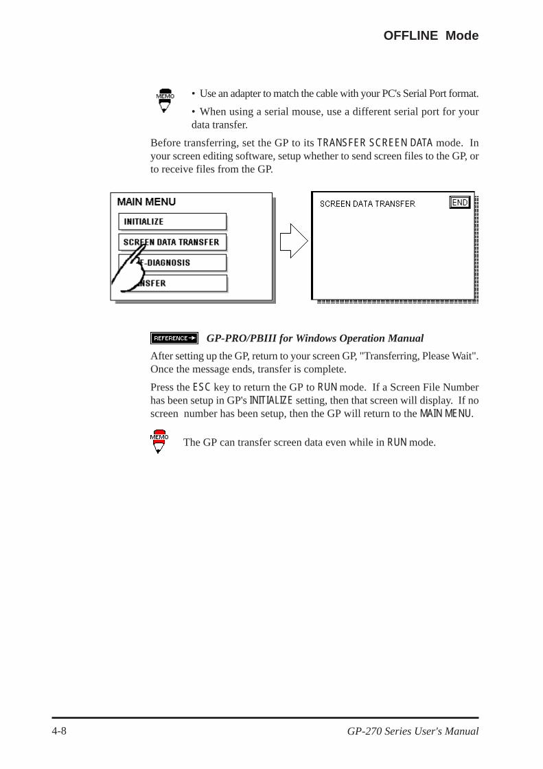
GP-PRO/PBIII for Windows Operation ManualAfter setting up the GP, return to your screen GP, "Transferring, Please Wait".Once the message ends, transfer is complete.
Press the ESC key to return the GP to RUN mode. If a Screen File Numberhas been setup in GP's INITIALIZE setting, then that screen will display. If noscreen number has been setup, then the GP will return to the MAIN MENU.
The GP can transfer screen data even while in RUN mode.
• Use an adapter to match the cable with your PC's Serial Port format.
• When using a serial mouse, use a different serial port for yourdata transfer.
Before transferring, set the GP to its TRANSFER SCREEN DATA mode. Inyour screen editing software, setup whether to send screen files to the GP, orto receive files from the GP.

Initialize
GP-270 Series User's Manual 5-1
Chapter 5
Initialize1. Initialize Screen 5. PLC SETUP2. Initialize Items 6. INITIALIZE MEMORY3. SYSTEM ENVIRONMENT SETUP 7. SET UP TIME4. SET UP I/O 8. SET UP SCREEN
Before running the GP unit, various GP setups must be verified. These arelisted under the INITIALIZE option in the MAIN MENU.
This chapter explains each of the Off-line mode's INITIALIZE items. However,there are 2 types of INITIALIZE setups, the 1:1 connection and the n:1 (multi-link)connection*1, and the setup information can differ for each.
The n:1 mark appears on menu items concerned only with the n:1 multi-linkconnection. If there is no mark, the menu item is common to both 1:1 and n:1connections.
1:1 Process concerning 1 GP connected with 1 PLC.
n:1 Process concerning multiple GP's connected with 1 PLC. The GP'ssuccessively pass a token (exclusive PLC interaction key) among them-selves to communicate with the PLC.
If you transfer your screen editing software's System file (S0), the GPoperates using the data contained therein. If the GP System file hasbeen correctly setup and transferred, the INITIALIZE setups become un-necessary.For more information about System file (S0) Sofoware Op-eration Manual,1.1.2 "Screen Types"
*1 PLC's that support the n:1 (multi-link) connection are limited. GP-PRO/PB3 PLC Connection Manual.
5.1 Initialize Screen

Initialize
GP-270 Series User's Manual5-2
5.2 Initialize Items
The contents of the Initialize setup items listed below are explained in this chap-ter. To learn about screen operations and numeric input Chapter 4,"Off-line Mode".
3 PLC SETUP n:1Set Up Operation SurroundingsStation SetupCustomize Setup
3 PLC SETUP 1:1Set Up Operation Surroundings
4 INITIALIZE MEMORY
5 SET UP TIME
6 SET UP SCREEN
7 FONT SETTING
2 SET UP I/OSet Up SIOSet Up I/OCommunication Setup
1 SYSTEM ENVIRONMENT SETUPSystem SetupSystem Area SetupGlobal Window SetupCharacter String Data Setup

Initialize
GP-270 Series User's Manual 5-3
5.3 SYSTEM ENVIRONMENT SETUP
GP environment adjustments are made here. The SYSTEM ENVIRONMENT SETUPincludes the SYSTEM SETUP, SYSTEM DATA AREA, GLOBAL WINDOW SETUP,and CHARACTER STRING DATA SETUP.
1. SYSTEM SETUP
STAND-BY MODE TIME (0-255)To protect the GP display screen, GP has been setup with a screen saver func-tion that automatically erases the screen when no GP operations have occurredfor the time entered here. A 0 entered in this field causes a normal display.
When SYSTEM DATA AREA's ( PLC Connection Manual) SCREENDISPLAY OFF*1 data is 0000h, and the following operations are not performed onthe screen for the number of minutes setup, the GP display erases.
• Change Screen• Touch Screen• Alarm Display
START TIME (0-255)This setup determines the start-up time of the GP. Use this setup to adjust thepower up sequence so that the GP starts up after the PLC.
TOUCH BUZZER SOUNDSetup whether or not the GP beeps when pressed.
BUZZER TERMINAL OUTPUTSetup whether or not the BUZZ signal is output from GP's AUX I/F. This optionis for an external buzzer.
PASSWORD (0-9999)The password setup here is necessary to enter INITIALIZE, Off-line mode, etc.The password (number) ensures protection of the GP setups as Off-line modecannot be entered inadvertently. Enter the optional number of your choice. Ifyou do not wish to use this setup, enter the default 0.
*1 When using the Direct Access format or the Memory Link format, the object addressbecomes +9 or +12 respectively.

Initialize
GP-270 Series User's Manual5-4
DATA TYPE OF SCREEN NO.This setup controls whether BIN or BCD format numbers are used when makingscreen changes. Screen numbers 1 to 8999 are available when set up in binaryformat; screen numbers 1 to 1999 are available when set up in BCD format.
2. SYSTEM AREA SETUP
SYSTEM AREA SETUP is necessary for the PLC to administer the GP, and pre-pare the PLC internal Data Memory (DM) and Data Register (D). Use thissetup to prepare the desired SYSTEM DATA AREA items.
PLC Connection Manual.
Press the and buttons to toggle between the SYSTEM AREA WRITEand READ screens.
Press the item—when the item is highlighted, it is selected.
System AREA SIZEThis field displays the size, in words, of the items selected in the SYSTEM AREA(all the WRITE and READ items).
When you press the SET key, the SYSTEM AREA CONTENTS screen appears andratifies the selected items
• The setup shown is efficient only when using the Direct Access format.
• The selected System Area items, as displayed on the screen, becomethe System Data Area.
When these five items, "Current Screen Number", "Error Status", "Clock Data(Current)", "Change Screen Number", and "Display On/Off", have been selected,word addresses are assigned to each item, in order, as shown on the next page.

Initialize
GP-270 Series User's Manual 5-5
The System Data Area selection process follows this formula [System Data StartAddress + n]. For example, if the System Area Start Address was D00200, andthe Change Screen Number option had been selected—if you refer to the Sys-tem Area Contents screen displayed above, because Change Screen Number'saddress is pegged at +6, its word address would be D00200+6=D00206.For more information on LS area 16 to19 PLC ConnectionManual,1.1.2 "LS Area Structure"
Addresses LS16 to LS19 arefixed as they control the GlobalWindow. Other items cannot beset to these addresses.
3. GLOBAL WINDOW SETUP
The GP unit can display one Global Window and two Local Windows at any onetime. The Global Window is common to all the display screens. The LocalWindow displays exclusively on the corresponding base screen. The GLOBALWINDOW SETUP is described here.
GLOBAL WINDOWWhen first entering the Global Window, select whether to Use, or Do Not Usethe Global Window. If you select Do Not Use, ignore the items described below.Selecting Use makes these options available by simply pressing the NEXT button.
With the GP-PRO/PBIII for Windows95 “Simulation” feature, the GP’s “SetupOperation Surroundings” area cannot be used.

Initialize
GP-270 Series User's Manual5-6
GLOBAL WINDOW ACCESSSetup the Global REGISTRATION NO. and the Window LOCATION as Direct orIndirect values. When set as Direct, the REGISTRATION NO. and Window LO-CATION selection are fixed to the values setup here. When set to Indirect, theWINDOW REG. NO. word address as prepared in the System Area is variable—which means it can have the REGISTRATION NO. written to it, and as a result,multiple window screens can be used as the Global window. Adjust the Globalwindow position using this same method, by writing the X,Y coordinates to theSYSTEM AREA's WINDOW LOCATION word addresses.
DATA FORMATSetup whether the REGISTRATION NO. and the Window LOCATION values areinputted as BIN or BCD numbers. Only Direct values can be setup in these fields.
REGISTRATION NO. (1-256)Setup the Window Screen Number used by the Global Window. This field isapplicable only when the GLOBAL WINDOW ACCESS is set to Indirect.
LOCATIONSetup for the Global Window LOCATION. This field is applicable only when theGLOBAL WINDOW ACCESS is set to Indirect.
4. CHARACTER STRING DATA SETUP
Character String Data ordering varies from manufacturer to manufacturer. Setupthe Character String Data order here to match the corresponding PLC.
Setup the CHARACTER STRING DATA MODE to match the PLC type.Device type and Tag settings are unavailable.
Find the data storage order for your PLC in the table, next page, and setup theCHARACTER STRING DATA MODE.
(I) Data Device Storage Order(II) Internal Word Byte LH/HL Storage Order(III)Internal Double-word Word LH/HL Storage Order

Initialize
GP-270 Series User's Manual 5-7
CHARACTER STRING DATA MODE List
II) Word Byte LH/HL OrderE.g. Characters A B C D
• 16 bit Device LH Order • 16 bit Device HL Order
D100D100
D100
D101
D100
D101
• 32 bit Device HL Order• 32 bit Device LH Order
I) DataDeviceStorageOrder
II) InternalWord, ByteLH/HLStorage Order
III) Double-wordInternal WordLH/HL StorageOrder
CharacterStringData Mode
Storagefrom Start
dataLH order
LH order 4HL order 2
HL orderLH order 5HL order 1
Storagefrom End
DataLH order
LH order 6HL order 7
HL orderLH order 8HL order 3
D100
D101
D102
D103
D100
D101
D102
D103
I) Data Device Storage OrderE.g. Characters A B C D E F G H
• Storage from Start Data • Storage from End Data

Initialize
GP-270 Series User's Manual5-8
III) Double-word Word LH/HL OrderE.g. Characters "A B C D E F G H I J"
• 16 bit Device LH Order • 16 bit Device HL Order
D100
D101
D102
D103
D104
D100
D101
D102
D103
D104
E.g. Characters "A B C D E F G H I J K L M N O P Q R S T"
• 32 bit Device LH Order • 32 bit Device HL OrderD100
D101
D102
D103
D104
D100
D101
D102
D103
D104
Relationship between K-tag Write Character Value and PLC Device• 16 bit DeviceGP stores the character string from the start, as groups of 2, into1 PLC Device.
When there are nine characters, they are arranged as shown below.
1 2 3 4 5 6 7 8 9 "
When the characters do not divide into 2 evenly, NULL is added.
• 32 bit DeviceGP stores the character string from the start, as groups of 4, into1 PLC Device.
When there are nine characters, they are arranged as shown below.
1 2 3 4 5 6 7 8 9 "
When the characters do not divide into 4 evenly, NULL is added.

Initialize
GP-270 Series User's Manual 5-9
COMMUNICATION RATEThe COMMUNICATION RATE (baud rate) is the data communication speed, meas-ured in bits per second (bps), between the GP and PLC. Match the COMMUNI-CATION RATE values in both the PLC and GP.
DATA LENGTHFor data communications, the DATA LENGTH (the first numeral) must be set upas 7-bit or 8-bit data. The second value is the STOP BIT, which must be set up aseither 1-bit or 2-bit.
PARITYSet up whether no parity check, or an odd or even number parity check will takeplace during communication.
CONTROLData flow CONTROL prevents the overflow of data sent back and forth. Selecteither X-CNTRL or ER-CNTRL.
COMMUNICATION FORMATSelect one of the following options for the communication format: RS-232C,RS-422 4 line, or RS-422 2 line.
When communicating with the Memory Link format using RS-422,select the 4-line option.
5.4 SET UP I/O
This section describes the communication setup with the host PLC and the setupfor any peripheral equipment. The SET UP I/O menu includes the SET UP SIO,SET UP I/O, and COMMUNICATION SETUP menus.
1. SET UP SIO
This menu runs the setups related to PLC communication. Match the settingslisted below with the SIO setup on the PLC host side.

Initialize
GP-270 Series User's Manual5-10
2. SET UP I/O
Touch operation and Force Reset setup, and Display Device adjustments aremade here.
TOUCH OPERATION MODESet up either One Point or Two Point input.
FORCE RESETSet up whether or not a FORCE RESET operation is in effect.
Steps to run FORCE RESETWhile holding down the bottom right corner (1) of the screen, press the upperright corner (2). At the same time, press the bottom left corner (3) to enter theFORCE RESET Operation. To activate Reset, press the RESET button; to transferto Off-line Mode, press OFFLINE.
• FORCE RESET occurs even during RUN mode and Off-line mode.
• The FORCE RESET mode cannot be entered while waiting for the GPto start.• Entering FORCE RESET is possible even when RUN operations (PLC<—>GP communication) do not occur.

Initialize
GP-270 Series User's Manual 5-11
CONTRAST ADJUSTMENTWhen this option is set On, CONTRAST ADJUSTMENTs can be made throughtouch input.
While pressing the upper right hand corner (1) of the screen, press the upper leftcorner (2) to enter CONTRAST ADJUSTMENT mode. Press the desired settingand the screen's contrast will change accordingly.
• For the GP270-LG** models, the lighter and darker settigs are on theopposite side.
• To exit CONTRAST ADJUSTMENT mode, press anywhere outside thecontrast option bar.• CONTRAST ADJUSTMENT mode cannot be entered while waiting forGP to start.• CONTRAST ADJUSTMENTs can be made even in the middle of RUNmode (PLC<—>GP communication).
LCD SETTING (Only for GP-270LG**)There are two options: REVERSE and NORMAL. When set to REVERSE, thescreen lighting becomes inverted.
Press the LCD SETTING item to change it from NORMAL to REVERSE, then pressthe SET button. The screen display reverses and returns to the previous screen.

Initialize
GP-270 Series User's Manual5-12
3. COMMUNICATION SETUP
These fields set when an error message is reported, after a GP<—>PLC com-munication error is detected. This ensures an error has actually taken place andnot just slight breaks in communication or slowness in processing data on oneside or the other.
RECEIVE TIMEOUTSet up how long the GP unit will wait when there is nothing being sent to it.(This is the Timeout Time.) However, if there is no cable connected up, thenregardless of the time set up here, the Timeout value would be 1 second. Thedefault value is 10 seconds.
When a value of over 30 seconds is set here, and a screen is transferredfrom the PC while a PLC Communication Time error has occurred, anerror may also appear on the PC side.
RETRY COUNTSet up the number of times the GP will try to send data when a Communicationerror occurs. The default value is 2 times.

Initialize
GP-270 Series User's Manual 5-13
5.5 PLC SETUP
Setup the System Area and the Unit number on this screen. Because 1:1 and n:1GP connections change the setup contents, check it before running any setups.
1. SET UP OPERATION SURROUNDINGS (1:1)
Setup the PLC System Data Area and the Unit Number here.
This setup is only necessary when using the Direct Access format.
SYSTEM AREA STARTING ADDRESSSetup the PLC's Data Register (D), Data Memory (DM), etc. allotted by theSYSTEM AREA STARTING ADDRESS. (The START DEV display changes withdifferent PLC's.)
UNIT NO.Set up the PLC UNIT number here. Make sure it matches the one set up in thePLC.
SYSTEM AREA READ SIZEWhen using a Block Display Trend Graph, setup the Reading Area Size (inword units) to match the Trend Graph's data size. Set this up when you wish toallocate the Reading Area in the PLC Data Register (D), or Data Memory (DM).
• If you are not using the Reading Area, leave the 0 default valuesintact. High Speed Communications can be secured as a result.
• When using Hitachi's HIDIC-S10 α Series, an extra item titled "Ex-tended Memory Address (HIDIC) [000000]" is added to the abovescreen display. Values accepted by the extended memory start addressare 0 (memory not extended), and 100000 to 1FF000.

Initialize
GP-270 Series User's Manual5-14
• When using Matsushita Electric's NEWNET-FP, an extra item titled"Monitor Register" is added to the screen display. If using 2 or moreCCU's (communication unit) as in the following diagram, and a GP isconnected to each CCU, select the 1:1 connection and setup the Moni-tor Register as "None".
2. SET UP OPERATION SURROUNDINGS (n:1)
This is the setup for the PLC System Data Area and the Unit Number for an n:1(multi-link) PLC connection. For more about the SYSTEM DATA AREA with then:1 (multi-link) connection, GP-PRO/PB 3 PLC ConnectionManual.
This setup is only necessary when using the Direct Access format.
SYSTEM AREA STARTING ADDRESSSetup the PLC's Data Register (D), Data Memory (DM), etc. allotted by theSYSTEM AREA STARTING ADDRESS.
UNIT NO.Set up the PLC UNIT number here. Make sure it matches the one set up in thePLC.
SYSTEM AREA READ SIZEWhen using a Block Display Trend Graph, setup the Reading Area Size (in

Initialize
GP-270 Series User's Manual 5-15
word units) to match the Trend Graph's data size. Set this up when you wish toallocate the Reading Area in the PLC Data Register (D), or Data Memory (DM).
• If you are not using the Reading Area, leave the 0 default valuesintact. This will allow you to perform high speed communication.
3. STATION SETUP (n:1)
The STATION SETUP, necessary for the n:1 (multi-link) setup, checks whethercorrect communications run with the connected GP System configuration.
NETWORK INFORMATION ADDRESSIn the n:1 (multi-link) connection, the Network Information uses 2 words in itscorrespondences. These 2 words are the Connection part and the Validationpart (described later in this section). Allocate these respective areas into thePLC's Data Register (D) or Data Memory (DM).
PLC Data Register
In the NETWORK INFORMATION ADDRESS, setup all the GP's connectedto the same link unit with the same address. Furthermore, when thereare 2 ports in the connected link unit, do not make these use the sameaddress.
• Connection PartThe word address for the Connection Part sets up the number of GP's connectedto the PLC, registered beforehand on the PLC side. When these GP's are con-nected to the PLC, the corresponding PLC bit numbers for the particular GPStations (see bottom) turn on.
When the GP is connected to the PLC, and the option of GP onlycorrespondence ends and Offline mode is entered, the GP StationNumber turns the corresponding PLC bit off.
Bit 15 Bit 0

Initialize
GP-270 Series User's Manual5-16
For example, when these 4 GP units—bit 0, bit 2, bit 3, bit 5—are connected,002D (h) is written here.
Connection Part 002D (h)
• Be certain to setup before running.• Turn bits not connected to the GP off.
• Verification PartThis area responds to the correspondence from each connected GP. When thesame bit numbers as the Connection Part turn On, the correspondence is ac-cepted by the Verification Part. In turn, the Station Numbers of the communi-cating GPs turn their corresponding PLC bit number on.
Bit 15 Bit 0
If the correspondence between the GP and PLC is correct, the same value as inthe Connection Part writes to the Verification Part.
For example, the value 002D (h) in the Connection Part, setup as the 0 bit, 2 bit,3 bit, and 5 bit, writes to the Verification Part as shown below.
Connection Part 002D (h)
Verification Part 002D (h)
• When the Connection Part and Verification Part do not match, a COM-MUNICATION ERROR occurs. Check the setup again.
• When changing the connection, first turn all the bits Off.
STATION NO.This is the setup for the number of GP Stations in use, as mentioned in the abovesection. The setup range is from 0 to 15, and the only other restriction is eachGP STATION NO. must be unique in the system. If STATION NO.'s are repeated, aCOMMUNICATION ERROR occurs.
• The STATION NO. is the number allocated to the particular GP unit.This number is not related to the Link Unit Machine number.

Initialize
GP-270 Series User's Manual 5-17
4. CUSTOMIZE SETUP
The Customize function alters the n:1 (multi-link) connection's communicationto make it more effective. To run communication efficiently, determine whetherto use Operation or Display priority with your GP. As a result, the communica-tion response speed can be upgraded, although the speed changes with the screeninformation.
PLC PRIORITYAccording to how the GP is used, select either Operation priority (OPE.) orDisplay priority.
• DisplaySetup the GP to this option when using the GP mainly as a monitor screen. TheGP will command a higher display speed as a result; however, the response timefor the touch panel's operations will slow.
• OperationSetup the GP to this option when using the GP mainly as an operation panel. Asa result, the GP will command better touch panel numeric input and switchresponse times.
Leaving the GP in this mode does not influence the touch panel operation re-sponse time of the rest of the GP's very much; however, the screen display re-newal cycle will slow down
• In a basic setup, run the same setup for all connected GP's.• To increase the display speed, restrict addresses used to consecutiveaddresses wherever possible. And make bit addresses consecutive tothe word unit.
• Display Priority and Operation Priority Speed DifferenceWhen using the Mitsubishi Electric Corp. A3A PLC, with a scan time of 20mswith consecutive addresses (80 words not included in the System Area), thedifference in speed when reading is as shown in the following graphs.

Initialize
GP-270 Series User's Manual5-18
Display Priority and Operation Priority Speed Difference
GP TOUCH MONOPOLIZEThe monopolizing of touch panel use can be set On or Off. When you want touse the PLC exclusively with a Momentary operation setup on the touch panel( GP-PRO/PB 3 PLC Connection Manual), turn GP TOUCH MONOPO-LIZE on.
When this setup is on, the touch panel uses the PLC exclusively whenever themomentary operation setup on the panel is pressed. In this way, you can use theinching operation with a momentary switch. When you stop pressing the panel,exclusive use ends.
MONOPOLIZE TIME (0~2550s)This field controls the length of time for the monopolize procedure when noother touch panel operations are performed. The Monopolize process beginswhen the System Data Area's 7th bit of word address LS14 turns on, and endseither when the bit turns off, or when the time set here passes.
• Pressing the touch panel in the middle of the monopolize processinterrupts the MONOPOLIZE TIME function, ending exclusive use.• When MONOPOLIZE TIME is set to 0, the monopolize function doesnot end automatically.
For more about the contents of System Data Area LS6 (status) and LS14 (con-trol) GP-PRO/PB 3 PLC Connection Manual.

Initialize
GP-270 Series User's Manual 5-19
5.6 INITIALIZE MEMORY
This command erases all the GP screen data.
• You cannot cancel the Initialization procedure after pressing the Startkey.• Initialization does not erase the SYSTEM SET UP, the SIO protocol,nor the internal clock setups.
To initialize the GP internal memory, enter the common password 1101, or thepassword entered in the SYSTEM SET UP screen.
Initialization takes 10 to 20 seconds.
5.7 SET UP TIME
Set up the internal timepiece of the GP. Make date and time corrections in theTIME SET UP fields.
The time—displayed on the screen using the Time Display function—is not completely accurate. At room temperature, the GP internal clockhas an accuracy of +/- 40 seconds/month. The surrounding tempera-ture and age of the unit can decrease the accuracy to +65 ~ -350 sec-onds/month. However, the screen Time displays only up to the minute.

Initialize
GP-270 Series User's Manual5-20
5.8 SET UP SCREEN
The initial screen display upon powering up, the alarm character size, and otherrelated items are setup here.
INITIAL SCREEN NO.Set up the screen file number that will display first upon powering up. If theBIN option for DATA TYPE OF SCREEN NO in SYSTEM SET UP had beenselected, enter a number from 1 to 8999. Or, if BCD was the option set up,then input a number from 1 to 1999.
ALARM MESSAGESet up the character size of the ALARM MESSAGE when the Alarm Bulletinis activated.
ONLINE ERROR DISPLAYSet up whether or not error messages display during RUN mode.
<When using syngle-byte characters>
<When using double-byte characters>
V size=4; H size=464×32 pixels
41V size=1; H size=116×8 pixels
2V size=2; H size=232×16 pixels
V size=1; H size=116×16 pixels
V size=2; H size=232×32 pixels
V size=4; H size=464×64 pixels

Initialize
GP-270 Series User's Manual 5-21
5.9 FONT SETTING
FONT SETTINGSelect the character font that displays during RUN mode. Available selec-tions are [EUROPE], [JAPAN], [KOREA], [CHINESE] and [TAIWAN-ESE].
When [FONT SETTING] is set to [JAPAN]
Full sized characters:
[STANDARD] : Full sized 16-dot characters display. When enlarged,this font will remain a 16-dot character. (Compatiblewith GP-*30 series units.)
[HIGH]: Any character which is Level 1 JIS Kanji Code standardlarger than 2 x 2 will display as a 32-dot character.Level 2 JIS Kanji Code standard characters, no matterwhat the current font setting is, will always displayusing 16 dots.(Compatible with GP-*50 and GP-*70 series units.)
[1,2]: Level 1 or 2 JIS Kanji Code standard characters that arelarger than 2 x 2, will display as 32-dot characters.
When [FONT SETTING] is set to any other type
A full sized character (except Alphabets) is displayed with 16-dot font, evenwhen it is displayed with an enlarged size. Half sized characters are dis-played as:
[STANDARD]: 16x8-dot charactersdisplay. When enlarged, this fontwill stay as 16x8-dot character. (Compatible withGP-*30 series units.)
[HIGH]: Alphabets and numerals (exceptions not included) willdisplay as high quality font-character.
[1,2]: Alphabets and numerals (exceptions not included) willdisplay as high quality font-character.
The [HIGH] selection is factory set.
KANJI FONT QUALITY

Initialize
GP-270 Series User's Manual5-22
1234567890123456789012345678901212345678901123456789012345678901234567890121234567890112345678901234567890123456789012123456789011234567890123456789012345678901212345678901123456789012345678901234567890121234567890112345678901234567890123456789012123456789011234567890123456789012345678901212345678901123456789012345678901234567890121234567890112345678901234567890123456789012123456789011234567890123456789012345678901212345678901123456789012345678901234567890121234567890112345678901234567890123456789012123456789011234567890123456789012345678901212345678901123456789012345678901234567890121234567890112345678901234567890123456789012123456789011234567890123456789012345678901212345678901
MEMO

GP-270 Series User's Manual 6-1
Run & Errors
This chapter describes the GP RUN and problem solving processes.
6.1 RUN
There are two ways of entering RUN mode, from powering up and from Off-linemode.
1. Powering Up
Activate the GP unit. After the unit has powered up, the START TIME value—setup in INITIALIZE/ SYSTEM SET UP—determines how long the display, illustratedbelow, appears, until it gives way to the screen number setup in the INITIALIZE/SET UP SCREEN menu. However, if a screen has not been set up, or if the screenset up does not exist, then the display below will remain.
Chapter 6
RUN and Errors1. RUN2. Troubleshooting3. SELF-DIAGNOSIS
2. Off-line Mode
Press Off-line mode's MAIN MENU item number 4, RUN. The INITIALIZE/ SET UPSCREEN option determines the first screen that appears in RUN mode, therebybeginning communication with the PLC. However, if a screen has not been setup, or if the screen set up does not exist, then the display above remains.

GP-270 Series User's Manual6-2
Run & Errors
6.2 Troubleshooting
This section describes how to find and resolve problems that may occur on theGP. If there is a problem on the PLC side, refer to the corresponding PLCmanual.
1. Trouble Types
Shown below are some problems that may occur while using this unit.
(1) No DisplayThe screen will not display even when the unit is powered On. Also, duringRUN mode, the screen disappears.
(2) No CommunicationThe GP unit cannot extract data from the host. An error message may ap-pear on the screen as a result. For more about error messages, refer to thesection in this chapter titled, "Error Messages".
(3) Touch Panels Do Not FunctionThe touch panel does not react when pressed, or the reaction time is veryslow.
(4) Off-line displays During RUN Mode.
Press the top left corner within 10 seconds of starting RUN to enterOff-line Mode.
E.g. After powering up, the initial Screen is equipped with a Switch inthe top left corner. If this Switch is pressed within 10 seconds, it changesthe GP status from RUN mode to Off-line mode.

GP-270 Series User's Manual 6-3
Run & Errors
For the first three problems, see the flowcharts listed on the following pages.
For the last problem, a SYSTEM ERROR may have developed while displayingthe Off-line mode screen. Refer to Chapter 6.4, "Error Messages—Details".However, this is not a problem when having entered Off-line mode by press-ing the top left corner within ten seconds of powering up.
• Because of the danger of electric shocks, make sure the power is notsupplied before wiring the unit.
• When changing the backlight, there is the danger of electric shocks andburns, so be sure to use gloves when working on the unit.
This section assumes that the cause of any problems comes from the GP, andnot from the host. When the host PLC is the problem, refer to the correspond-ing PLC manual.

GP-270 Series User's Manual6-4
Run & Errors
D i s c o n n e c t t h epower cable.
No Screen Display
NOIs it using the correctpower voltage?
Does the power lampturn On?
NOHas data transferredfrom the Screen
editor?
2. No Display
Follow the flowchart below when the screen does not display when poweringup, or the screen turns Off by itself during RUN mode, to find an appropriatesolution.
Plug in the power cable properly. Chapter 2, "Specifica-
tions".
NO
YES
YES
YES
Transfer screen data from thes c r e e n e d i t i n g s o f t w a r e .
Chapter 4.5, "TransferScreen Data".
Turn Off the power.
Fix the connection of the power ca-ble. Chapter 3, "Instal-lation and Wiring".
YES
NOIs the powercable connectedproperly to this unit?
YESTurn Off the power and reconnectthe communication cable.Does turning on the
power cause a display?
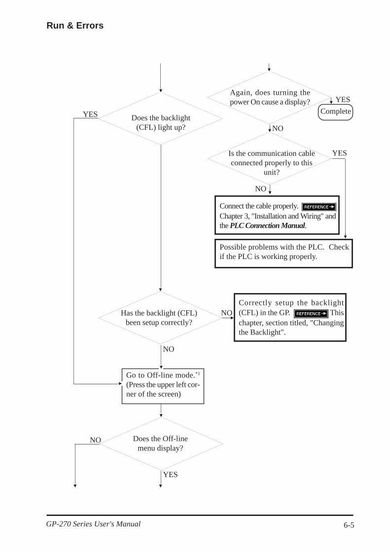
GP-270 Series User's Manual 6-5
Run & Errors
NO
Again, does turning thepower On cause a display?
CompleteYES
NO
Is the communication cableconnected properly to this
unit?
Possible problems with the PLC. Checkif the PLC is working properly.
Connect the cable properly. Chapter 3, "Installation and Wiring" andthe PLC Connection Manual.
NO
YES
Does the backlight(CFL) light up?
YES
NOHas the backlight (CFL)been setup correctly?
Correctly setup the backlight(CFL) in the GP. Thischapter, section titled, "Changingthe Backlight".
Does the Off-linemenu display?
NO
NO
YES
Go to Off-line mode.*1
(Press the upper left cor-ner of the screen)

GP-270 Series User's Manual6-6
Run & Errors
*1 To make the Off-line screen appear, turn the power Off, then back On, and press the upperleft corner of the screen within 10 seconds.
*2 When you run the FEPROM CHECK in SELF-DIAGNOSIS, all the screen data gets erased.Be sure to make a backup of all the screens.
Set up the correct Screen filenumber. Chapter5, "Initialize".
YES
NOSee if INITIALIZE/SCREEN SET UP is OK.
Erase the data that has been writ-ten. When using Direct Access, theaddress is +9; when using MemoryLink, the address is +12. For moreon the SYSTEM DATA AREA
PLC Connec t i onManual.
Has Off data been writtento the SYSTEM DATA
AREA?
NO
YES
YES
NO
There is a problem with the GPunit. Please contact your localGP distributor.
Run SELF-DIAGNOSIS'INTERNAL FEPROMCHECK*2. Is it OK?
Internal FEPROM Data has altered.Initialize FEPROM, transfer thedata, and try using again.

GP-270 Series User's Manual 6-7
Run & Errors
NO
YES
Is the SIO cable at-tached properly to this
unit?
NO
Has the correct PLCprotocol (Table file)
been selected?
Does not communicate
Turn Off the power switch.
NO
3. Would Not Communicate
When the GP will not communicate with the host PLC, follow the flowchartbelow to discover the origin of the problem and find a suitable response.
Or, if an error message displays on the screen, check the error code—Error Message section in this chapter—to find the appropriate solution.
Setup the Table file that correspondswith the connected PLC. Software Operation Manual.
Attach the SIO cable unit properly,making sure all connections aresecure. PLC Connec-tion Manual.
YES
YES
Disconnect all the cables except thepower cable and turn the unit On.
For RS-422, use the solution providedin the dotted rectangle, above.
Is the Termination Resis-tor setup correctly?
Setup the Termination Resistor in thecorrect position with the correct val-ues.Resistor position and values changewith each PLC type. When usingthe Di rec t Access fo rma t ,
PLC Connec t ionManual.

GP-270 Series User's Manual6-8
Run & Errors
Are the correspondingSIO INITIALIZE settings
OK?
Is the SELF-DIAGNOSIS/SIO CHECK OK?
Is the Tag setupcorrect?
NO
YES
YES
NO
YES
NO
Enter correct settingsand values.
Chapter 5,"Initialize".
Check the tag data, andcorrect the setup val-ues.
TagReference Manual.
There is a problem with the GPunit. Please contact your localGP distributor.
Possible problems with thePLC. Check if the PLC isworking properly.
• To run SELF-DIAGNOSIS's SIO CHECK options, special tools becomenecessary.For details about SELF-DIAGNOSIS, refer to the SELF-DIAGNOSIS sec-tion in this chapter.

GP-270 Series User's Manual 6-9
Run & Errors
Touch panel not respond
Is INITIALIZE's SETUP TOUCH PANEL data
correct?
YES
YES
NO
In the INITIALIZE/ SET UP TOUCHPANEL option, enter values applica-ble to the Touch Operation Mode.
Chapter 5, "Initialize".
Set the addresseswithin the allow-able range, or re-define the touch
YES
area.
NO
NO
There is a problem with the GPunit. Please contact your localGP distributor.
Run SELF-DIAGNOSIS/TOUCH PANEL CHECK to
see if it is OK.
Are the T-tags setproperly?
4. The Touch Panel Does Not Respond
When the touch panel does not react, or its reaction time is very slow after it ispressed, please follow the flowchart below to find the origin of the problem, andthe appropriate solution.
Disconnect all but the Powercable.

GP-270 Series User's Manual6-10
Run & Errors
6.3 SELF-DIAGNOSIS
The GP unit is equipped to check its own System and Interface for any prob-lems. Use it to help diagnose any problems.
1. SELF-DIAGNOSIS Item List
• DISPLAY PATTERNDisplays all the figures and tiling patterns to check if they are correct.
• TOUCH PANELChecks the touch panel squares.
• FEPROM CHECKSUMRuns the GP internal memory's (FEPROM) system and protocol checksum.
• FRAME BUFFERChecks the GP internal display memory (FRAME BUFFER).
• *TOOL CONNECTORChecks the control lines and input/output lines for the tool connector.
• INPUT PORT (for Digital's maintenance use only)Runs a check on the Input Port.
• *SIO CHECKChecks the input/output lines for the RS-232C and RS-422 terminals.
The SELF-DIAGNOSIS items marked with an asterisk (*) require spe-cial tools. Please prepare the required tool for each test.

GP-270 Series User's Manual 6-11
Run & Errors
2. SELF-DIAGNOSIS—Details Of Each Item
This section explains the contents of SELF-DIAGNOSIS. For information abouthow to operate the Screen, Chapter 4, "Off-line Mode"; for informa-tion about how to set up the Special Tools, Chapter 3, "Installationand Wiring".
DISPLAY PATTERNChecks the drawing function and Kanji ROM for when the device contents willnot display correctly, by running checks on the various screen pattern displays.If everything is normal, OK displays; if there is a problem, NG displays.
TOUCH PANELTouch Panel check. Checks if each touch cell highlights when pressed.
INTERNAL FEPROM CHECKSUM (System & Protocol)The Internal FEPROM System and Protocol check searches for any problemsthat may arise during operations.
When the FEPROM is normal, OK displays; if there is a problem, an error mes-sage appears. This check does not erase the System or Protocol.
FRAME BUFFERThe Frame Buffer (display memory) Check looks for any display problems thatmay develop. When everything is normal, OK displays; when there is a problem,an error message displays.
TOOL CONNECTOR LOOP BACKUse the Tool Connector Control line and Send/Receive line check when the GPcannot send and receive data from the PC. To run the check, connecting a ToolConnector Check Loop Back Cable (Dsub25 pin female connection) mountedto the Downloading Cable (provided in your software package) is necessary.See diagram next page.When everything is normal, OK displays; when there is a problem, an errormessage displays.
(Created by User)
Data Transfer cable
(GPW-CB02) *1

GP-270 Series User's Manual6-12
Run & Errors
INPUT PORTUsed by Digital for maintenance purpose.
SIO CHECKChecks the RS-232C and RS-422 I/O lines for areas where correspondence prob-lems develop. In the menu, select which check to run. To run the check, a serialinterface cable connection becomes necessary. If all is normal, OK displays; ifthere is a problem, an error message appears.
The Serial Interface cable wiring for each check is as shown below.• DTR CHECKConnect the DTR Loop Back cable to the GP's serial interface. If all is normal,OK displays; if there is a problem, an error message appears.
• RTS CHECKConnect the RTS Loop Back cable to the GP's serial interface. If all is normal,OK displays; if there is a problem, an error message appears.
• RS-422 CHECKConnect the RS-422 Loop Back cable to the GP's serial interace. If all is nor-mal, OK displays; if there is a problem, an error message appears.

GP-270 Series User's Manual 6-13
Run & Errors
6.4 Error Message
This section explains the messages that appear when an error has occurred inthe GP unit during RUN mode. The origin of the problem behind each errormessage is explained with appropriate ways of disposing of the error.
After a problem has been solved, turn the power Off, then On, and restart theGP.
1. Error Message List
The error messages listed below appear on the GP unit. Instructions on how tofind and solve error messages are explained on the following pages.
• SYSTEM ERROR• ILLEGAL ADDRESS IN SCREEN DATA• UNSUPPORTED TAG IN SCREEN DATA• PLC NOT CONNECTED (02:FF) and (02:F7)• PLC NOT RESPONDING (02:FE)• RECEIVE DATA ERROR (02:FD)• PLC COM. ERROR• SCREEN MEMORY DATA IS CORRUPT• CLOCK SETUP ERROR• SCREEN TRANSFER ERROR• OBJ. PLC HAS NOT BEEN SETUP
• GP STATION NO. DUPLICATION ERROR (02:F9)• NETWORK ADDRESS ERROR (02:F8)
If there is more than one error, the GP displays the error message forthe last error detected.

GP-270 Series User's Manual6-14
Run & Errors
2. Error Messages—Details
SYSTEM ERRORIndicates a fault in the basic operations of the GP.
Following the error message, an error code, as shown, will appear. Report theerror number, and details on how the error developed, to your local GP distribu-tor.
• SYSTEM ERROR ( 03 : x x )Displays when a PC transferred file cannot be rebuilt.
03 : x xError No.Constant Value
• SYSTEM ERROR ( x x x : x x x : x x x )Displays in RUN mode when a file cannot be rebuilt.
x x x : x x x : x x x
Error No. 2Error No. 3
Error No. 1
• Offline mode displays while in RUN modeWhen the GP changes to Off-line mode without pressing the screen, there is apossibility that the screen data has been damaged. When the screen data isdamaged, after the SYSTEM ERROR displays, the screen automatically reverts toOff-line mode after about 10 seconds. Run the INITIALIZE MEMORY commandand transfer the GP screen data again from your PC.
ILLEGAL ADDRESS IN SCREEN DATAThis error message is caused by an overlap of addresses.
Following the error message, error codes, as listed below, appear. If the errorcannot be fixed, please report the error code and details on how the error devel-oped to your local GP distributor.
ILLEGAL ADDRESS IN SCREEN DATA ( 0 0 B : x x x : x x x )Error No. 2Error No. 1
See the Table next page

GP-270 Series User's Manual 6-15
Run & Errors
Overlapping AddressesError 1 Error 2 Contents
0C1
191 All or part of the T-File or S-tag address range overlapthe addresses of System Data Area.192
193
0C2
194 All or part of the System Data Area address, A-File, orS-tag address range overlap the addresses setup in aT-File.195
196
0C3
197 All or part of the T-File, or the S-tag or K-tag addressrange overlap the address range set in an A-file.198
199
Tag Name/Part ID No.
WordAddress
Tag Format
N1 99 BCD32
The N-tag is set to 32 bits, meaning it uses two word addresses. Sincethe first address is 99, the second address must be 100. Address 100 isineligible for use since it has already been used for the System DataArea.
*1
*1
*1
UNSUPPORTED TAG IN SCREEN DATAA list of tag(s) in use that are unsupported by the current GP version appear withthis error message. Setup the tags to correspond with the GP.
For details about tags, Tag Reference Manual.
PLC NOT CONNECTED (02:FF) (02:F7)Displays when communication with the PLC has stopped for over 60 seconds,when there is a transmission timeout error, or when there is excess noise.
Check the correspondence cable wiring and connect correctly.
*1 For details about the T-File (trend graph) and A-File (alarm messages), refer to the TagReference Manual.
Overlapping addresses, other than the ones mentioned above, can alsocause the Illegal Address message.
E.g. When the starting address of the System Data Area is set to100, and the tag below is setup:

GP-270 Series User's Manual6-16
Run & Errors
PLC NOT RESPONDING (02:FE)Displays when there is a Reply Timeout Error, or when there is excess noise.
The origin of the problem and the matching solutions are listed in the tablebelow.
ORIGIN SOLUTION
1. The power for the PLC host is notactivated.2. GP unit INITIALIZE setup (Setup I/O,PLC Setting) is incorrect.3. The host and GP powering upprocess was incorrect.4. The Communication Cable was notconnected properly.
1. Turn On the host's power switch.2. Setup the unit correctly and match upwith the current host and CommunicationCable.3. Turn the host's power On first, wait 2~3seconds, then power up the GP unit.4. Check the Communication Cable wiringand connect it up properly.
RECEIVE DATA ERROR (02:FD)This problem arises as a result of one of these three:
• There is a problem in trying to receive the data• The connected PLC and the PLC setup for the data is different• Noise
These errors, except for noise, appear when the Communication Cable is pulledout when the GP unit is On, or when normal communication operations arebeing run, but the GP has been powered Off, then back On. To solve the prob-lem, simply begin running transmissions again.
When the error is a result of noise, correct any improper connections.
GP STATION NO. DUPLICATION ERROR (02:F9)This error appears for one of two reasons:
• The GP number is same as the station number for another GP. Check allthe GP station numbers.
• In the middle of correspondences, the PLC power has been turned On/Off.Reset the power on the PLC and GP.
NETWORK ADDRESS ERROR (02:F8)The SIO address setup for the GP is different from other GP's. Check the ad-dress setup for all the GP's.

GP-270 Series User's Manual 6-17
Run & Errors
PLC COM. ERRORAppears when the address setup for tags exceeds the address range on the hostside. Check the Error Number that appears and use the following table to eradi-cate the problem.
PLC COM. ERROR ( 02 : x x )Error code (see the table below)Constant Value
Error # Origin Solution
FC(MtoM type) There is a data formatproblem with the message received.
Check the data being transferred on thehost side.
FB
The address set on a tag, the addressused for storing data for Trend Graph, orthe address registered with an alarmmessage is out of a set range. (addressrange error)* Memory to Memory type.* Siemen's PLC Series
* When using Memory to Memory Type:Set the addresses within the set range ofthe System Area (0~2047), then send thecorrected information.
* When using Siemens' Series PLC Type:Set up the data block in the PLC where theSystem Data area is.
FAAddress range error Set the addresses within the allowable
device range.
53
When using a Matsushita ElectronicsPLC, and too many tags are used on thescreen, the PLC cannot receive anydata.
Decrease the number of screen tags.
51
The tag address, Trend graph datastorage address, Alarm messageRegistry address, and the like, do notexist in the PLC's internal memory.(In the case of Fuji Electric PLC)
Setup the addresses in a device range thatexists.
Others When the Error Number displays, different for each PLC, look up the error number inthe indicated PLC manual or, report the error number to the PLC maker.
• Disregard the above table if Error Number 51 appears and you areusing a PLC other than Fuji Electric. Look up the error contents inyour PLC manual and follow the instructions therein.
• Disregard the above table if Error Number 53 appears and you areusing a PLC other than Matsushita Electronics. Look up the errorcontents in your PLC manual and follow the instructions therein.
• In Hitachi's HIDIC H (HIZAC H) Series, the error code is dividedinto 2 bytes, whereas the GP Error Number is composed of 1 bytecodes. (see next page)
E.g. Reply Return Display

GP-270 Series User's Manual6-18
Run & Errors
Command Code Error No.
When the displayed error number is 8*, or 5*, use only the left columnas the error number.
• In Toshiba's PROSEC T Series, the Error Code is 4 places long; onthe GP, Error Numbers are displayed and changed into Hexadecimal.
E.g.
• With the Allen-Bradley PLC-5 and SLC-500 Series, the EXT/STSerror codes have been re-mapped to start at D0 HEX, so they will notconflict with other error codes. When looking up the error number inthe PLC manual, subtract D0 h from the GP error code to get its errorvalue.
E.g. GP Error Code PLC Error CodeD1 —> 01EA —> 1A
SCREEN MEMORY DATA IS CORRUPTDisplays when the checksum of the screen memory data does not match becauseof a corruption in the screen files.Error codes, as shown below, follow the error message. By referring to the errorcode, check the screens that have errors. When a screen file has been corrupted,delete that file, and make a new one (or recall a backup copy if available).
SCREEN MEMORY DATA IS CORRUPT ( x x x x : x x x x )
The number of screens thathave errors (Decimal)
The Screen Number that has an error.(Displays only one per Screen Number.)
CLOCK SET UP ERRORThis message displays when the backup battery for the internal clock is dead. Ifthe battery is incorrectly replaced, the battery may explode. To avoid the danger,please do not replace the battery yourself. When the battery needs a replacement,please consult with your local GP distributor.
After changing the backup battery, set up the internal clock. Chapter5, "Initialize".
The life span of the backup battery depends on the battery's ambienttemperature and the amount of current being charged and used. Thetable below gives a general indication of how long the battery will last.

GP-270 Series User's Manual 6-19
Run & Errors
BatteryTemperature under 40 C
Between40~ 50 C
Between50~ 60 C
ExpectedLife Span over 10 yrs. over 4.1 yrs. over 1.5 yrs
oo o
SCREEN TRANSFER ERRORDisplays when an error occurs in the data transmission from the screen editor tothe GP panel. Try re-transmitting the screen data.
OBJ. PLC HAS NOT BEEN SETUP (02:F9)The host PLC setup in GP's INITIALIZE Screen does not match the PLC in use.Use the Error Code that follows the error message to select the proper PLC typein the GP and correct the INITIALIZE setup.
OBJ. PLC HAS NOT BEEN SETUP ( x x )
The PLC number (Hexadecimal)written onto the System FileSee the Table, next page.

GP-270 Series User's Manual6-20
Run & Errors
PLC Number indicated by error code
PLC # FileExt.
PLC TYPE PLC # FileExt.
PLC TYPE
0 DL0 SYSMAC - C 18 DLO FLEX-PC
1 DL1 MELSEC - AnN (Link) 1B DLR TC200
2 DL2 NEW SATELLITE JW 1F DLU SIEMENS S5 90-115
3 DL3 FA500 20 DLV DIEMENS S5 135-115
4 DL4 MICREX-F 21 DLW SIEMENS S5 3964(R) protocol
6 DL6 TOYOPUC-PC2 22 DLX Allen Bradley PLC-5
7 DL7 MEWNET-FP 28 DLY Allen Bradley SLC500
8 DL8 HIDIC-S10 63 DNQ FA500M n:1 SIO
9 DL9 Memocon-SC 66 DNT GP FANUC 90SNP
B DLB MELSEC-AnA (LINK) 67 DNU HIZAC EC
D DLD SYSMAC-CV 68 DNV IDIC 1
E DLE PROSEC EX2000 69 DNW IDIC 2
10 DLG HIZAC H 6A DNX IDIC3
11 DLH MELSEC-FX 6B DNY FANUC Power Mate
12 DLI MELSEC-F2 6C DNZ MICRO3
14 DLK KOSTAC SG8 81 DOK MELSEC-AnN (CPU)
15 DLL PROSEC T 8B DOU MELSEC-AnA (CPU)
16 DLM MEMORY LINK (SIOType)

Maintenance
GP-270 Series User's Manual 7-1
7.1 Regular Cleaning
Cleaning the DisplayWhen the surface or the frame of the display gets dirty, soak a soft cloth in waterwith a neutral detergent, wring the cloth tightly, and wipe the display.
• Do not use paint thinner, organic solvents, or a strong acid compound to cleanthe unit.
• Do not press the touch-screen panel with hard or pointed objects, such as amechanical pencil, for it may damage the surface.
Installation Gasket ReplacementThis gasket protects the GP and improves its water resistance. For instructionson installing the gasket, Chapter 3.1 "Installation".
A gasket, which has been used for a long period of time, may have scratches ordirt on it, and could have lost much of its water resistance. Change the gasketperiodically (or when scratches or dirt become visible).
Chapter 7
Maintenance1. Regular Cleaning2. Periodic Checkup3. Changing the Backlight

Maintenance
GP-270 Series User's Manual7-2
7.2 Periodic Maintenance Check Points
To maintain your unit in its best condition, please check your unit periodically.
Inspection Items:
Surrounding Environment • Is the temperature within the allowable range? (0 to 50o Celsius)
• Is the humidity within the specified range? (20 to 85%RH)
• Is the atmosphere free of corrosive gas?
GP Temperature • When the GP unit is mounted into a panel, the surrounding temperature refers
to the temperature inside the cabinet.
Electrical Specifications• Is the input voltage appropriate? (DC20.4 to 27.6V)
Attachments • Is the cable connected properly? Not loose?
• Are the mounting brackets holding the unit securely?
• Are there many scratches or traces of dirt on the rubber gasket?

Maintenance
GP-270 Series User's Manual 7-3
7.3 Changing the Backlight
Please have your service personnel do the replacement.
• Whenever changing the Backlight, be sure the power has been turned Off.• When the unit is still On, high voltage runs through the Backlight area—do
not touch.• While the unit is still hot, be sure to wear cotton gloves to prevent injury.• When the power has just been turned Off, the unit and Backlight are still very hot.
Be sure the backlight you order matches your GP type.
Change the Backlight following the steps below.Be sure to use gloves.
1) Turn off the GP's power supply.
2) Detach the GP's power cord terminals.( A )
3) Use a screwdriver to unfasten the case's top face attachment screws. ( B )
4) Open the GP's rear cover, and detach the backlight power connector.( C )
5) Push the backlight lock tab to the right and pull out the backlight.( D )
6) Insert a new backlight, and re-attach the power connector.
7) Use the GP's guide tabs to re-attach the GP's rear cover and tighten theattachment screws. Be careful not to pinch any of the connector wiringbetween the GP's front and the rear covers.( E )
GP Type Backlight Model No.GP270-LG**GP270-SC**
GP270-BL00-MS

Maintenance
GP-270 Series User's Manual7-4
A C Power Connector
DC E
Guide
BacklightLock TabInternal cover
P o w e r c o r dterminals
B
Backlight Change Steps


![Med · 270 342 [(+72) (270+72) 472 (270+72 [(+72) tztžU +130) (+102)] (+130) 520 (270+250) 1270+102 752 (270+102 (+480) 750 270+480) 852 (270+102 (270+102](https://static.fdocuments.net/doc/165x107/5fb23750d464052f95224679/med-270-342-72-27072-472-27072-72-tztu-130-102-130-520-270250.jpg)


![1 270 020 900 | 0 275 007 000 | 0 275 007 001 | 1 270 020 ...Bosch ebike Systems 0 276 001 XXX | (17.1.11) Komputer HMI 8ZDJL GRW\F] FH EH]SLHF]H =VWZD Opis produktu i specyfikacja](https://static.fdocuments.net/doc/165x107/5ea2e066f8d0ad4c2d16b627/1-270-020-900-0-275-007-000-0-275-007-001-1-270-020-bosch-ebike-systems.jpg)