
GP 03-06-01 Piping for Instruments June 2005 -...
305
Transcript of GP 03-06-01 Piping for Instruments June 2005 -...

GP 03-06-01 Piping for Instruments June 2005
Refining/Chemicals For ExxonMobil Use Only Version 1.1.0
Page 1 of 15 ExxonMobil Development Company
Piping for Instruments
GP 03-06-01
Scope
[I] This Global Practice (GP) covers the piping associated with field instrument installations and instrument air systems. Piping for sample transport and conditioning systems of process analyzers are
covered by GP 15-08-02.
[I] An asterisk (*) indicates that either a decision by the Owner's Engineer is required, that additional information is to be furnished by the Owner's Engineer, or that information for Owner's Engineer
approval is to be supplied by Vendor or Contractor.

GP 03-06-01 Piping for Instruments June 2005
RFCH For ExxonMobil Use Only Version 1.1.0
Page 2 of 15 ExxonMobil Development Company
Table of Contents
1. Required References ............................................................................................ 3
1.1. Global Practices–ExxonMobil Engineering Practices ................................... 3
1.2. API–American Petroleum Institute................................................................ 3
1.3. ASME–American Society of Mechanical Engineers ..................................... 4
1.4. ASTM–American Society for Testing and Materials ..................................... 4
1.5. ISA–The Instrumentation, Systems, and Automation Society ...................... 4
2. Additional Requirements...................................................................................... 4
2.1. ISO–International Standards Organization ................................................... 4
2.2. Other Requirements ..................................................................................... 4
3. Mounting of Instruments and Access Requirements......................................... 5
4. Take-Off Connections ........................................................................................... 5
5. Connecting Piping and Tubing ............................................................................ 7
6. Thermowell Connections...................................................................................... 8
7. Flow Meters ........................................................................................................... 9
7.1. Orifice Meters ............................................................................................... 9
7.2. Positive Displacement Meters and Turbine Meters ...................................... 9
8. Pressure Instruments ......................................................................................... 10
9. Level Instruments ............................................................................................... 10
9.1. Displacer and Float Type Instruments........................................................ 10
9.2. Differential Type Instruments...................................................................... 11
9.3. Gauge Glasses........................................................................................... 11
10. Instrument Air Systems...................................................................................... 12
10.1. Instrument Air Tubing ................................................................................. 12
10.2. Instrument Air Distribution System ............................................................. 13
10.3. Instrument Air Dryer ................................................................................... 13
Record of Change ....................................................................................................... 14
Attachment: Purpose Codes Definitions.................................................................. 15

GP 03-06-01 Piping for Instruments June 2005
RFCH For ExxonMobil Use Only Version 1.1.0
Page 3 of 15 ExxonMobil Development Company
1. Required References
[I] This Section lists Practices and Standards that are generically referenced and assumed to be a part of this document. Unless otherwise specified herein, use the latest edition.
1.1. Global Practices–ExxonMobil Engineering Practices
GP 03-06-02 Piping at Control and Protective System Valve Stations
GP 03-09-01 Winterizing and Protection Against Ambient Temperatures
GP 03-18-01 Piping Fabrication Shop or Field
GP 04-02-01 Auxiliary Structures for Operation and Maintenance
GP 14-03-01 Fireproofing
GP 15-01-03 Instruments for Storage Tanks and Vessels
GP 15-02-01 Temperature Instruments
GP 15-03-01 Pressure Instruments
GP 15-04-01 Flow Instruments
GP 15-05-01 Level Instruments
1.2. API–American Petroleum Institute
API MPMS 14.3.2 Manual of Petroleum Measurement Standards Chapter 14 - Natural Gas
Fluids Measurement; Section 3 - Concentric, Square-Edged Orifice
Meters; Part 2 - Specification and Installation Requirements
API MPMS 5.2 Manual of Petroleum Measurement Standards Chapter 5 - Liquid Metering Section 2 - Measurement of Liquid Hydrocarbons by
Displacement Meters
API MPMS 5.3 Manual of Petroleum Measurement Standards Chapter 5 - Metering Section 3 - Measurement of Liquid Hydrocarbons by Turbine Meters
API MPMS 5.4 Manual of Petroleum Measurement Standards Chapter 5 - Metering
Section 4 - Accessory Equipment for Liquid Meters
API RP 551 Process Measurement Instrumentation
API RP 552 Transmission Systems

GP 03-06-01 Piping for Instruments June 2005
RFCH For ExxonMobil Use Only Version 1.1.0
Page 4 of 15 ExxonMobil Development Company
1.3. ASME–American Society of Mechanical Engineers
ASME B1.20.1 Pipe Threads, General Purpose (Inch)
ASME B16.36 Orifice Flanges
ASME SEC VIII D1 BPVC Section VIII - Rules for Construction of Pressure Vessels - Division 1
1.4. ASTM–American Society for Testing and Materials
ASTM A 269 Standard Specification for Seamless and Welded Austenitic Stainless
Steel Tubing for General Service
ASTM B 16/B 16M Standard Specification for Free-Cutting Brass Rod, Bar and Shapes for Use in Screw Machines
ASTM B 68 Standard Specification for Seamless Copper Tube, Bright Annealed
ASTM B 111/B 111M Standard Specification for Copper and Copper-Alloy Seamless
Condenser Tubes and Ferrule Stock
ASTM D 1047 Standard Specification for Poly(Vinyl Chloride) Jacket for Wire and Cable
1.5. ISA–The Instrumentation, Systems, and Automation Society
ISA 7.0.01 Quality Standard for Instrument Air
2. Additional Requirements
* [I] The following standard shall be used with this GP as specified by Purchaser.
2.1. ISO–International Standards Organization
ISO 5167-1 Measurement of Fluid Flow by Means of Pressure Differential Devices
Inserted in Circular Cross-Section Conduits Running Full - Part 1:
General Principals and Requirements
2.2. Other Requirements
1) [S] No fluids, except instrument air, potable water, and fresh air from a safe location, shall be piped
into the control house. Instrument air that is backed up by nitrogen shall not be piped into control houses or other walk-in enclosed spaces.
2) [S] Downstream of the first isolation block valve, all piping, tubing, instruments, and instrument
accessories in contact with the process or any purge medium shall have a suitable
pressure/temperature rating and material for the service conditions.

GP 03-06-01 Piping for Instruments June 2005
RFCH For ExxonMobil Use Only Version 1.1.0
Page 5 of 15 ExxonMobil Development Company
3) [S] Valves and their respective control cabling, tubing, and associated field equipment that are
required to remain operable during a fire require fireproofing in accordance with GP 14-03-01.
4) * [O] Leak testing of instrument pressure piping and air supply piping shall be in accordance with the requirements of the project specification. Leak testing of signal transmission systems shall be in
accordance with ISA 7.0.01.
3. Mounting of Instruments and Access Requirements
1) [C], [O] The preferred instrument installation is close coupled (line mounted).
2) * [M], [S] All instruments, including thermocouples, shall be accessible for maintenance. Instrument
process connections that require maintenance shall also be accessible, including accessories such as rod-out connections, condensate pots, and seal connections. Permanent platforms for instrument
maintenance are preferred. In cases where personnel safety is not compromised, alternative methods
of access may be approved by Owner's Engineer. All indicating instruments shall be installed to be readable from grade and/or the related operational area. Pressure and differential pressure
instruments shall be supported by means other than the process connections.
3) [R] When piping or platforms are subject to process or equipment induced vibrations (e.g., fluid
solids units, reciprocating compressors, lines in two-phase flow, hydraulic shock from rapid valve action) a more stable location for the instrument mounting shall be selected. In addition,
piping/tubing bends shall be used to mitigate vibration.
4) [S] Insertion type instruments shall be equipped with a blowout prevention device, such as a
mechanical stop or safety chain. This device must prevent the unintentional removal of the instrument while under process pressure. Insertion type instruments that are installed in a toxic or
flammable service and rely on a non fire resistant elastomer seal (PTFE, for example) for process
pressure containment, shall be equipped with a secondary seal that will prevent the process fluid from being released in the event that the instrument is subjected to a fire.
5) [M], [O] In addition to any vendor-supplied nameplate, each installed instrument shall be provided
with an identification nameplate containing the tag number and the process service description.
These nameplates shall be fabricated from a corrosion resistant material (16 U.S. gauge stainless steel or equivalent is preferred) and shall be permanently and securely fastened to the instrument by either
stainless steel wire or drive screws. The identification nameplate shall be readable from grade or the
associated maintenance platform. If any process connection is not viewable from its associated
instrument, then a separate tag nameplate is required at each such process connection.
6) [R] Unless otherwise specified, flow meters shall be installed upstream of the associated control
valve(s).
4. Take-Off Connections
1) [M] A gate valve shall be installed in each instrument take-off connection, and shall be located as
close to the vessel or line as possible, consistent with manual opening and closing of the valve. In no case shall the valve outlet be a distance greater than 9 in. (225 mm) from the branch connection. The

GP 03-06-01 Piping for Instruments June 2005
RFCH For ExxonMobil Use Only Version 1.1.0
Page 6 of 15 ExxonMobil Development Company
use of elbows between the take-off point and the valve is prohibited. Take-off connections, including
the first valve, shall be in accordance with the line service classification.
2) [M], [O] Separate process take-off connections shall be furnished for each instrument except as follows, in which case separate block valves shall be provided.
a) Dual range installations requiring two instruments
b) Pressure measurement associated with flow metering or suppressed range pressure instruments
All other proposals to use the same set of process take off connections for more than one instrument
shall require the approval of the Owner's Engineer.
3) [R] For process lines, the minimum size of take-off connections shall be NPS ½ (15 mm). Where the
line service classification (including corrosion allowance) will result in an ID of less than 0.466 in. or 12 mm (equivalent of Schedule 160), the connection size shall be increased to NPS ¾ (20 mm).
Alternatively, a suitable alloy material with a smaller required corrosion allowance may be used.
4) [R] For pressure vessels, a minimum NPS 2 (50 mm) nozzle-sized flanged valve with the same
pressure/temperature rating and metallurgy as the vessel shall be used. The outboard side of the valve shall be suitable for connection to the instrument. Thermowells are excluded from this valve
requirement.
5) [R], [O] Connections to vessel bottom shall be avoided whenever possible. When this is not possible,
bottom connection shall extend into the vessel at least 3 in. (75 mm) beyond the inside of the shell or vessel lining. All bottom connections shall be approved by the Owner's Engineer.
6) [R], [O] Connections to vessel top shall be avoided whenever possible where the upper fluid is a
liquid. When this is not possible, a valved vent connection shall be furnished at the highest point in
the instrument piping. All top connections shall be approved by the Owner's Engineer.
7) [O] Take-off connections for pressure instruments shall be horizontal except for gauges, which can be vertical.
8) [O] Horizontal process takeoff connections for all differential pressure type flow meters are preferred.
Gas takeoffs may be installed from horizontal to 90 degrees above horizontal and liquid connections
from horizontal to 45 degrees below horizontal.
9) [O] The mounting location for differential pressure type flow instruments and pressure instruments with relation to take-off connections shall be as shown in Table 1.

GP 03-06-01 Piping for Instruments June 2005
RFCH For ExxonMobil Use Only Version 1.1.0
Page 7 of 15 ExxonMobil Development Company
Table 1: Mounting Provisions
Instrument LocationFluid
Line Mounted Pedestal Mounted
Liquids Level with or below take-off Below take-off
Non-Condensing Gases Level with take-off Above take-off (1)
Steam/Condensing Vapors
At least 2 in. (50 mm) below take-off Below take-off
Cryogenic Liquids Level with take-off with the connection to the
instrument being beyond the 100% vapor point (usually 12 in. [300 mm]) from the line or vessel)
Above take-off
Note
(1):
If necessary to mount below take-off connection, make take-off horizontal and:
(a) for liquid filled vertical legs, provide fill connections and (for displacement type) seal pots,
or(b) for gas filled vertical legs, provide heat tracing, knock-out pots, or drain pots with drain
valves as dictated by the amount of condensate expected.
5. Connecting Piping and Tubing
1) * [R] Connecting piping or tubing, between take-off connection (block valve) and instrument, is as follows:
a) Material shall be either carbon steel pipe or stainless steel tubing Type 316 or 304, unless another material is required for the process or utility fluids handled. Tubing is preferred.
b) Carbon steel piping shall use threaded or flanged joints. Seal welding of threaded connections,
where required, shall be in accordance with GP 03-18-01. Pipe shall be ½ in. NPS (15 mm), seamless, Schedule 80 (3.73 mm) minimum wall thickness. Fittings and valves shall be forged
steel.
c) Stainless steel tubing shall use compression fittings. Threaded tube fitting connections shall not
be seal welded. Tubing shall be seamless, ½ in. OD x 0.049 in. minimum wall thickness (or 12
mm OD x 1.5 mm minimum wall thickness). Double ferrule compression fittings shall be used. Tubing fitting manufacturers shall be approved by the Owner's Engineer.
2) [R] If the instrument connection is smaller than the connecting piping, then the connecting piping
shall be reduced at the instrument.
3) [O] Instrument piping and tubing shall be sloped between the take-off connection and the instrument
when the instrument is mounted above or below the connection. The slope shall be at least 1:12 and always in the same direction. Piping and tubing runs shall be designed and installed to prevent fluid
pockets or traps.
4) [C] Pipe and tubing bends shall be used in place of elbows where practicable.

GP 03-06-01 Piping for Instruments June 2005
RFCH For ExxonMobil Use Only Version 1.1.0
Page 8 of 15 ExxonMobil Development Company
5) [E], [M] Drain, fill, and blowdown connections shall be provided as follows:
a) All sealed installations, including those with condensate legs or pots, shall be provided with fill and drain connections.
b) All steam flow meter manifolds shall be provided with a valved blowdown connection.
c) All gauge glasses shall be provided with a valved drain connection and a plugged cleanout
connection at the top.
d) Instruments in hydrocarbon or toxic services shall have a valved drain connection.
6) [M] Tees shall be used, to permit rodding, in any service where solids can build up at the take-off
connection. Sufficient clearance shall be provided to allow the use of rodout devices.
7) [S], [M] The instrument installation shall provide a mechanism for depressurizing piping downstream of the take-off process isolation valve when it is closed.
8) * [O] The minimum flow rates for Purge Systems at process takeoff connections shall be as shown in
Table 2.
Table 2: Minimum Flow Rates
Instrument Service Minimum Velocity Purge
Liquids 0.25 in./sec, 6 mm/sec Liquid Purge
Gas Solids: 24 in./sec, 600 mm/sec Gas Purge
Cracking 3 ft/sec, 0.9 m/sec Gas Purge
Coking 6 ft/sec, 1.8 m/sec Gas Purge
Flame Scanner Connections (1) 2 ft/sec, 0.6 m/sec Gas Purge
Note (1): Higher velocities may be required to prevent sensor burnout. Each installation shall be approved by Owner's Engineer.
9) * [O] The use of seal, condensate, and knock out pots shall be approved by Owner's Engineer.
10) * [M] Seal welding of instrument lead line connections downstream of the first block valve shall be
approved by the Owner's Engineer.
11) * [S] Quarter-turn valves shall not be used as the final valve to the atmosphere or in isolating applications, unless the Owner's Engineer approves their use for selected services.
6. Thermowell Connections
1) [S] Thermowells installed in a threaded connection shall be seal welded to prevent removal of the thermowell.
2) [O] The minimum pipe size for thermowell installation is NPS 4 (100 mm). For NPS 3 (75 mm) or smaller piping, the line size shall be swaged to NPS 4 (100 mm).

GP 03-06-01 Piping for Instruments June 2005
RFCH For ExxonMobil Use Only Version 1.1.0
Page 9 of 15 ExxonMobil Development Company
3) [O] Thermowell connections shall be a minimum of 10 pipe diameters downstream of the junction of
two streams of different temperatures. For desuperheating stations, the thermowell connection shall
be located no closer than 20 pipe diameters downstream of the desuperheater. Where this is impractical, the thermowell connection may be located after the first elbow downstream of the
desuperheater.
4) [I] When a check thermocouple is required in a separate thermowell, its thermowell connection shall
be located within 18 in. (450 mm) of the primary thermowell connection.
5) [O] Thermowell connections located in downcomers of towers shall be located in liquid 2 in. to 4 in.
(50 mm to 100 mm) from the bottom of the downcomer.
6) [O] Thermowells located in vapor spaces of towers shall not be placed in dead spots, or between webs
or trusses. They shall be located as close as possible to the tray above.
7) [S] Where flange mounted thermowells are required, the flanged thermowell shall be constructed from a single forging or fabricated and certified to meet ASME pressure vessel code requirements.
7. Flow Meters
1) * [I] All custody transfer applications and meter prover connections shall be approved by Owner's
Engineer.
2) [O] All valves used in a prover system that can provide or contribute to a bypass of fluid around the prover of the meter or to leakage between the prover and the meter shall be double block-and-bleed
valves, or the system shall be provided with valves and piping that are equivalent. A method for
checking valve leakage in the valve system shall be provided.
7.1. Orifice Meters
1) [I], [O] For liquid or gas service, API MPMS 14.3.2 states the minimum length of pipe upstream and downstream of orifices.
2) [O] If static pressure measurement is required for a compressible fluid, it shall be from a dedicated
tap whose location shall be in accordance with GP 15-04-01.
3) [O] Metering orifices shall be installed in horizontal lines where possible. If installed in vertical
lines, flow shall be upward for liquids and downward for gases and for vapors, both condensing and non-condensing.
4) [M] Thermowell connections, pressure instrument connections, sample connections, vents, drains,
etc. shall not be located within the straight run length requirements of Section 7.1, Item 1.
5) [R] Straightening vanes shall not be used.
7.2. Positive Displacement Meters and Turbine Meters
1) * [O], [R] Where vapor can occur or air be entrained, an air eliminator shall be installed. A combined air eliminator and strainer assembly may be used with approval of the Owner's Engineer.
2) [O] The installation shall be designed to insure a liquid filled meter at all times.
GP 03-06-01 Piping for Instruments June 2005
RFCH For ExxonMobil Use Only Version 1.1.0
Page 10 of 15 ExxonMobil Development Company
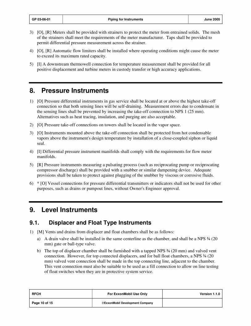
3) [O], [R] Meters shall be provided with strainers to protect the meter from entrained solids. The mesh
of the strainers shall meet the requirements of the meter manufacturer. Taps shall be provided to
permit differential pressure measurement across the strainer.
4) [O], [R] Automatic flow limiters shall be installed where operating conditions might cause the meter
to exceed its maximum rated capacity.
5) [I] A downstream thermowell connection for temperature measurement shall be provided for all
positive displacement and turbine meters in custody transfer or high accuracy applications.
8. Pressure Instruments
1) [O] Pressure differential instruments in gas service shall be located at or above the highest take-off connection so that both sensing lines will be self-draining. Measurement errors due to condensate in
the sensing lines shall be prevented by increasing the take-off connection to NPS 1 (25 mm).
Alternatives such as heat tracing, insulation, and purging are also acceptable.
2) [O] Pressure take-off connections on towers shall be located in the vapor space.
3) [O] Instruments mounted above the take-off connection shall be protected from hot condensable
vapors above the instrument's design temperature by installation of a close-coupled siphon or liquid
seal.
4) [I] Differential pressure instrument manifolds shall comply with the requirements for flow meter manifolds.
5) [R] Pressure instruments measuring a pulsating process (such as reciprocating pump or reciprocating
compressor discharge) shall be provided with a snubber or similar dampening device. Adequate
provisions shall be taken to protect against plugging of the snubber by viscous or corrosive fluids.
6) * [O] Vessel connections for pressure differential transmitters or indicators shall not be used for other purposes, such as drains or pumpout lines, without Owner's Engineer approval.
9. Level Instruments
9.1. Displacer and Float Type Instruments
1) [M] Vents and drains from displacer and float chambers shall be as follows:
a) A drain valve shall be installed in the same centerline as the chamber, and shall be a NPS ¾ (20 mm) gate or ball-type valve.
b) The top of displacer chamber shall be furnished with a tapped NPS ¾ (20 mm) and valved vent connection. However, for top connected displacers, and for ball float chambers, a NPS ¾ (20
mm) valved vent connection shall be made in the top connecting line, adjacent to the chamber.
This vent connection must also be suitable to be used as a fill connection to allow on line testing of float switches when they are in protective system service.

GP 03-06-01 Piping for Instruments June 2005
RFCH For ExxonMobil Use Only Version 1.1.0
Page 11 of 15 ExxonMobil Development Company
2) [O] When an external chamber is used in services where vaporization of the liquid is possible when
exposed to ambient temperatures, precautions like extra thick insulation shall be taken to minimize
boiling.
3) [O] A stilling well shall be provided for all internally mounted displacer or float type level
instruments. The well shall be mounted plumb; shall be open-ended, drilled, or slotted along its entire
length; and shall have a smooth interior finish. A bar or rod shall be welded across the bottom of the
well to retain the displacer or float, should it become disconnected from the instrument shaft.
4) [O] External level instrument vessel connections and internal level instruments shall be oriented to
prevent impingement of entering streams. External level instruments shall be mounted plumb.
For displacers or floats subjected to turbulence, provisions shall be made for shielding the connections or guiding the fluid to eliminate the effect of turbulence on the torque tube or float shaft
assembly.
9.2. Differential Type Instruments
[O] Differential type level instruments in liquid services, except those with remote seals (preferred), shall be installed as follows:
1) The instrument shall be installed level with the lower vessel connection. When the temperature of the
process fluid is higher than the maximum operating temperature for the instrument, the instrument shall be located 12 in. (300 mm) below the lower vessel connection.
2) For upper impulse line dry-leg installations: A drain pot and valved drain at the low point shall be
installed. The upper impulse line shall be heated as necessary to ensure a dry leg.
3) When upper impulse line is sealed with vessel liquid, a bypass valve between the high and low pressure connections shall be installed at the instrument, and a valved vent using a globe valve at the
upper vessel connection. When other seal material is used, the bypass valve is not required.
9.3. Gauge Glasses
1) * [R] Horizontal take-off connection length (i.e., vessel connection, vessel isolation valve, and
outboard horizontal impulse line) shall not exceed 15 in. (375 mm). If longer lengths are required,
they shall be approved by the Owner's Engineer. All take-off connection lines exceeding 15 in. (375 mm), and all take-off connection lines subject to vibration (regardless of length), shall be braced in
two planes, per GP 03-18-01.
2) [S], [O] Where gauge glasses are specified for use in non-fouling processes where a toxic or flammable vapor cloud may be formed in the event of gauge glass failure, the gauge glass piping shall
include a ball type (excess flow) check valve or similar device at each gauge glass column
connection. The design shall permit commissioning of the gauge glass column without the need for
external bypass piping.
3) * [M], [O] Separate vessel connections shall be installed for gauge glasses and each level instrument. Pipe columns (bridles) may be used to minimize vessel connections when approved by the Owner's
Engineer. When a pipe column (bridle) is used, a block valve shall be installed at each pipe column
(bridle) to vessel connection and at each instrument to pipe column (bridle) connection. Pipe columns (bridles) shall not be less than NPS 2, Schedule 80 pipe for carbon steel or NPS 2, Schedule
40 pipe for stainless steel.

GP 03-06-01 Piping for Instruments June 2005
RFCH For ExxonMobil Use Only Version 1.1.0
Page 12 of 15 ExxonMobil Development Company
4) [O] If a pipe column (bridle) arrangement is used for a three fluid system (e.g., interface), a balance
line shall be connected between the vessel and the pipe column. The line shall be located so that the
point where it connects to the vessel is covered by the middle fluid for all expected fluctuations of the middle fluid levels. If this cannot be achieved with one balance line, additional balance lines shall be
used. If the top vessel connection is not always submerged in the top fluid, balance lines will be
required for the top fluid also.
5) * [M], [O] Gauge glasses shall be provided to augment level instruments in liquid service, including displacer, float, differential pressure, and hydrostatic head types. The visible range of the gauge glass
shall equal or exceed the maximum range of the level instrument. Specifically excluded are fluid
solid or tank gauge services. Other exclusions shall be specified by the Owner's Engineer.
6) [O] Gauge glass shall, if possible, be installed such that the mid-range of the gauge glass coincides with the mid-range of its associated level instrument.
7) [S] Gauge glasses shall be located away from sources of damage such as roadways, work areas, and
mobile equipment lanes.
8) [M], [O] Gauge glasses shall be oriented with respect to walkways, platforms, ladders, or stairways so that they are conveniently visible to operators and are readily accessible for blocking off, venting, and
draining for maintenance. If permanent lighting has not been specified for thru-vision gauge glasses,
the gauges shall also be positioned to be accessible for illumination from the rear and simultaneous observation by an operator with a flashlight.
10. Instrument Air Systems
10.1. Instrument Air Tubing
1) * [R] Single tube runs to field instruments and control valves shall use 0.25 in. diameter 0.035 in.
wall thickness stainless steel tubing as a minimum. PVC covered copper tubing may be used where
approved by Owner's Engineer.
Individual pneumatic signal lines generally shall not be supported from larger lines. However in remote locations, individual pneumatic signal lines may be supported by lines NPS 2 and larger.
Tubing shall be supported in accordance with the recommendations in API RP 552, Sections 21 and 22. The method of support shall be approved. In areas exposed to potential mechanical damage,
pneumatic signal lines shall be protected by a continuous support (for example, a structural steel
angle or channel).
2) [O], [R] Each air consuming instrument shall have a filter, a pressure reducing valve, and a pressure gauge to indicate the reduced pressure. A combination filter regulator with gauge is acceptable for
such applications. Instruments on a filtered, regulated panelboard air supply are excepted from
having one set per instrument.
Filter body and regulator valve body (or combined filter-regulator body) shall be of metal
construction. Downstream tubing shall be stainless steel. Supply lines to instruments shall terminate
with shutoff valves not more than 36 in. (900 mm) from the instruments. Supply lines shall be installed with sufficient flexibility to allow for normal piping/equipment movements. Tubing valves
in highly corrosive environments, marine (offshore), and chloride bearing environments shall have
Type 316 stainless steel bodies. Tubing valves shall have Teflon or graphite packing, stainless steel
stems, and TFE stem tips or seats where tight shutoff is required.
GP 03-06-01 Piping for Instruments June 2005
RFCH For ExxonMobil Use Only Version 1.1.0
Page 13 of 15 ExxonMobil Development Company
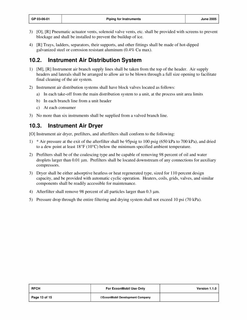
3) [O], [R] Pneumatic actuator vents, solenoid valve vents, etc. shall be provided with screens to prevent
blockage and shall be installed to prevent the buildup of ice.
4) [R] Trays, ladders, separators, their supports, and other fittings shall be made of hot-dipped galvanized steel or corrosion resistant aluminum (0.4% Cu max).
10.2. Instrument Air Distribution System
1) [M], [R] Instrument air branch supply lines shall be taken from the top of the header. Air supply
headers and laterals shall be arranged to allow air to be blown through a full size opening to facilitate
final cleaning of the air system.
2) Instrument air distribution systems shall have block valves located as follows:
a) In each take-off from the main distribution system to a unit, at the process unit area limits
b) In each branch line from a unit header
c) At each consumer
3) No more than six instruments shall be supplied from a valved branch line.
10.3. Instrument Air Dryer
[O] Instrument air dryer, prefilters, and afterfilters shall conform to the following:
1) * Air pressure at the exit of the afterfilter shall be 95psig to 100 psig (650 kPa to 700 kPa), and dried
to a dew point at least 18°F (10°C) below the minimum specified ambient temperature.
2) Prefilters shall be of the coalescing type and be capable of removing 98 percent of oil and water
droplets larger than 0.01 m. Prefilters shall be located downstream of any connections for auxiliary compressors.
3) Dryer shall be either adsorptive heatless or heat regenerated type, sized for 110 percent design
capacity, and be provided with automatic cyclic operation. Heaters, coils, grids, valves, and similar
components shall be readily accessible for maintenance.
4) Afterfilter shall remove 98 percent of all particles larger than 0.3 m.
5) Pressure drop through the entire filtering and drying system shall not exceed 10 psi (70 kPa).

GP 03-06-01 Piping for Instruments June 2005
RFCH For ExxonMobil Use Only Version 1.1.0
Page 14 of 15 ExxonMobil Development Company
Record of Change
Version 1.0.0 Date: 06/01
Location Action Description
Initial Publish
Version 1.0.0 Date: 12/03
Global Practice version number and format updated to comply with new
process; however, original publish date remains, and no content was
modified.
Version 1.1.0 Date: 06/05
General From this version onward, revision bars in the right margin will be used
to identify technical changes from the last version of the GP.
Section 1 Modification Updated reference mnemonic from ASTM B 111 to ASTM B 111/B
111M. Updated reference titles.

GP 03-06-01 Piping for Instruments June 2005
RFCH For ExxonMobil Use Only Version 1.1.0
Page 15 of 15 ExxonMobil Development Company
Attachment: Purpose Codes Definitions
Code Description
C Assigned to paragraphs containing specifications whose primary purpose is reduced costs.
Reduced cost in this context refers to initial investment cost and does not include Life-Cycle
cost considerations. Life-Cycle cost considerations are captured under reliability,
maintainability, or operability purpose codes.
E Assigned to paragraphs containing specifications whose primary purpose is driven by
environmental considerations. Environmental considerations typically include specifications
intended to protect against emissions/leakage to the air, water, and/or soil. Deviations from the specifications contained in such paragraphs require formal review and approval according to
local environmental policy.
I Assigned to paragraphs that provide only clarifying information such as Scope statements,
definitions of terms, etc.
M Assigned to paragraphs containing specifications whose primary purpose is to provide for
maintainability of equipment or systems. Maintainability provisions are those that facilitate the
performance of maintenance on equipment/systems either during downtimes or during on-
stream operations.
O Assigned to paragraphs containing specifications whose primary purpose is to assure
operability of equipment or systems. Operability is the ability of the equipment/system to
perform satisfactorily even though conditions are off-design, such as during startups, process swings, subcomponent malfunction, etc.
R Assigned to paragraphs containing specifications whose primary purpose is to improve or
assure the reliability of equipment or systems. Reliability is a measure of the ability of
equipment/systems to operate without malfunction or failure between planned maintenance interventions.
S Assigned to paragraphs containing specifications whose primary purpose is avoidance of
personnel or operational safety incidents. Any deviation from the specifications contained in
such designated paragraphs requires formal review and approval according to local safety policy.
Personnel Safety: Refers to the avoidance of recordable personnel injuries; i.e., burns, cuts,
abrasions, inhalation, or exposure to dangerous substances, etc., that could result in medical treatment, restricted work, lost-time incidents, or
fatalities.
Operational
Safety:
Refers to the prevention and control of process releases, fires, explosions,
etc.
GP 03-16-01 Flanged Joints, Gaskets, and Bolting October 2008
Refining/Chemicals, Downstream Imperial Oil
For Company Use Only Version 3.1.0
Page 1 of 19 ExxonMobil Development Company
Copyright Waiver ExxonMobil Development Company and ExxonMobil Pipeline Company hereby license the use of ExxonMobil Engineering Practices System (EMEPS) Global Practices (GPs) for use by any ExxonMobil division, subsidiary, or more-than-50%-owned affiliate. The GPs may be downloaded and modified as necessary for project and affiliate use. Written permission from ExxonMobil Development Company or ExxonMobil Pipeline Company is not required. However, any modified GPs must be renumbered to a project-specific or affiliate-specific number to distinguish them from the GPs on the EMEPS web site. ExxonMobil operated joint ventures may utilize GPs to create project-specific or location-specific specifications. It is the responsibility of individual affiliate or joint venture to ensure that the use of GPs and their derivatives is limited to joint venture related business and not disclosed or used outside the JV without appropriate EM management approval.
Flanged Joints, Gaskets, and Bolting
GP 03-16-01
Scope
1) [I] This Global Practice (GP) covers the design of flanged joints for piping, and the selection of
flanges, flange facings, gaskets and bolting for piping, and equipment flanged nozzles and manways.
2) [I] Orifice flanges, valve bonnets, and elastomeric o-ring gaskets are outside the Scope of this Practice.

GP 03-16-01 Flanged Joints, Gaskets, and Bolting October 2008
RFCH, DIOL For Company Use Only Version 3.1.0
Page 2 of 19 ExxonMobil Development Company
Table of Contents
Table of Tables .............................................................................................................. 3
1. Required References ............................................................................................ 4
1.1. Global Practices–ExxonMobil Engineering Practices ................................... 4
1.2. API–American Petroleum Institute................................................................ 4
1.3. ASME–American Society of Mechanical Engineers ..................................... 4
1.4. ASTM–American Society for Testing and Materials ..................................... 5
2. Definitions.............................................................................................................. 5
3. Flanged Joints....................................................................................................... 5
4. Flanges................................................................................................................... 6
5. Gaskets .................................................................................................................. 8
6. Bolting.................................................................................................................. 10
Appendix: Acceptable Metric Equivalents for Temperatures................................. 15
Record of Change ....................................................................................................... 16
Attachment: Purpose Code Definitions.................................................................... 19

GP 03-16-01 Flanged Joints, Gaskets, and Bolting October 2008
RFCH, DIOL For Company Use Only Version 3.1.0
Page 3 of 19 ExxonMobil Development Company
Table of Tables
Table 1: Flange Standards........................................................................................... 7
Table 2: Bolting Requirements ................................................................................. 10
Table 3: Flange Facings and Gaskets ...................................................................... 12
GP 03-16-01 Flanged Joints, Gaskets, and Bolting October 2008
RFCH, DIOL For Company Use Only Version 3.1.0
Page 4 of 19 ExxonMobil Development Company
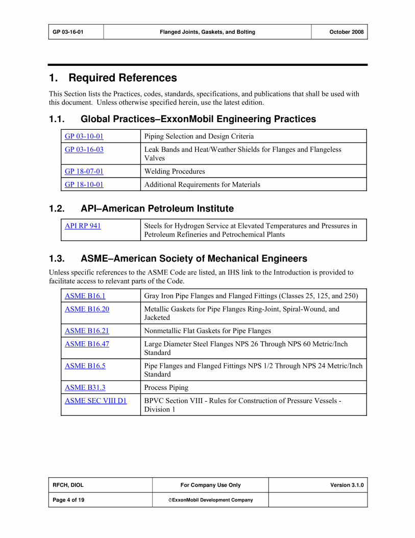
1. Required References
This Section lists the Practices, codes, standards, specifications, and publications that shall be used with this document. Unless otherwise specified herein, use the latest edition.
1.1. Global Practices–ExxonMobil Engineering Practices
GP 03-10-01 Piping Selection and Design Criteria
GP 03-16-03 Leak Bands and Heat/Weather Shields for Flanges and Flangeless
Valves
GP 18-07-01 Welding Procedures
GP 18-10-01 Additional Requirements for Materials
1.2. API–American Petroleum Institute
API RP 941 Steels for Hydrogen Service at Elevated Temperatures and Pressures in
Petroleum Refineries and Petrochemical Plants
1.3. ASME–American Society of Mechanical Engineers
Unless specific references to the ASME Code are listed, an IHS link to the Introduction is provided to
facilitate access to relevant parts of the Code.
ASME B16.1 Gray Iron Pipe Flanges and Flanged Fittings (Classes 25, 125, and 250)
ASME B16.20 Metallic Gaskets for Pipe Flanges Ring-Joint, Spiral-Wound, and Jacketed
ASME B16.21 Nonmetallic Flat Gaskets for Pipe Flanges
ASME B16.47 Large Diameter Steel Flanges NPS 26 Through NPS 60 Metric/Inch
Standard
ASME B16.5 Pipe Flanges and Flanged Fittings NPS 1/2 Through NPS 24 Metric/Inch Standard
ASME B31.3 Process Piping
ASME SEC VIII D1 BPVC Section VIII - Rules for Construction of Pressure Vessels -
Division 1

GP 03-16-01 Flanged Joints, Gaskets, and Bolting October 2008
RFCH, DIOL For Company Use Only Version 3.1.0
Page 5 of 19 ExxonMobil Development Company
1.4. ASTM–American Society for Testing and Materials
ASTM A 193/A 193M Standard Specification for Alloy-Steel and Stainless Steel Bolting
Materials for High Temperature or High Pressure Service and Other Special Purpose Applications
ASTM A 194/A 194M Standard Specification for Carbon and Alloy Steel Nuts for Bolts for
High Pressure or High Temperature Service, or Both
ASTM A 320/A 320M Standard Specification for Alloy-Steel and Stainless Steel Bolting Materials for Low-Temperature Service
ASTM F 436 Standard Specification for Hardened Steel Washers
2. Definitions
1) [I] Hydrogen Service, as used herein, is to be consistent with the definition provided in GP 18-10-01. Equipment is in hydrogen service when the design temperature is greater than the CS curve in API RP
941 for the given hydrogen partial pressure.
2) [I] Combustible liquids�High flash liquids [flash points 100 F (38 C) or higher] when handled at
temperatures 15 F (8 C) below their flash point or lower.
3) [I] Flammable liquids�Low flash liquids [flash point below 100 F (38 C)]; and high flash liquids
[flash point 100 F (38 C) or higher] when handled at temperatures above or within 15 F (8 C) of
their flash point.
4) [I] Flammable materials�Flammable liquids; hydrocarbon vapors; and other vapors such as hydrogen and carbon disulfide that are readily ignitable when released to atmosphere.
3. Flanged Joints
1) [R] The selection of flanged facings and gaskets shall be per Table 3.
2) [S] [A] [R] Electrically insulated flanged joints require approval by the Owner's Engineer. Insulating
flanged joints are required for:
a) Isolation of all lines heated by electric impedance heating systems.
b) Protection of marine terminal loading stations to electrically isolate on-board (tanker or barge)
piping from the pier piping under any of the following circumstances:
i) At cathodically protected marine terminals
ii) Where loading arms or electrically bonded oil cargo hoses are used
iii) For loading and unloading products classified as flammable liquids
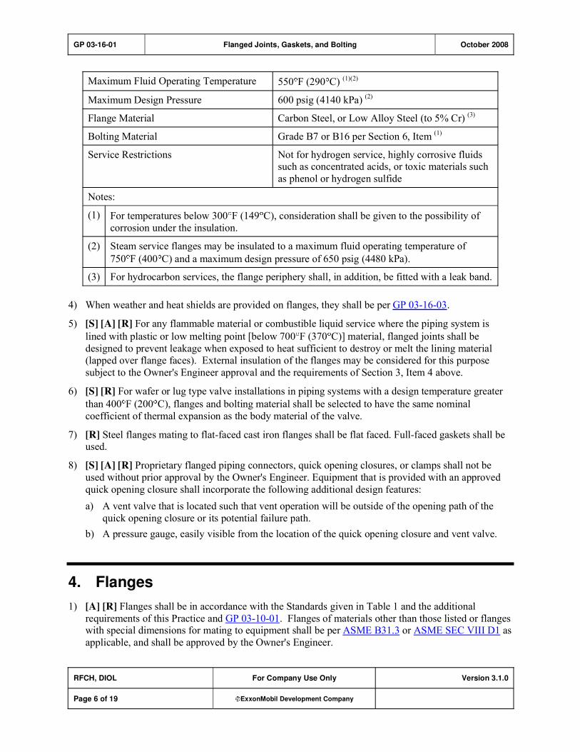
3) [*] [R] When specified, hot service thermal insulation of flanges is permitted where all of the
conditions in the following table are met:
GP 03-16-01 Flanged Joints, Gaskets, and Bolting October 2008
RFCH, DIOL For Company Use Only Version 3.1.0
Page 6 of 19 ExxonMobil Development Company
Maximum Fluid Operating Temperature 550 F (290 C) (1)(2)
Maximum Design Pressure 600 psig (4140 kPa) (2)
Flange Material Carbon Steel, or Low Alloy Steel (to 5% Cr) (3)
Bolting Material Grade B7 or B16 per Section 6, Item (1)
Service Restrictions Not for hydrogen service, highly corrosive fluids such as concentrated acids, or toxic materials such
as phenol or hydrogen sulfide
Notes:
(1) For temperatures below 300 F (149 C), consideration shall be given to the possibility of
corrosion under the insulation.
(2) Steam service flanges may be insulated to a maximum fluid operating temperature of
750 F (400 C) and a maximum design pressure of 650 psig (4480 kPa).
(3) For hydrocarbon services, the flange periphery shall, in addition, be fitted with a leak band.
4) When weather and heat shields are provided on flanges, they shall be per GP 03-16-03.
5) [S] [A] [R] For any flammable material or combustible liquid service where the piping system is
lined with plastic or low melting point [below 700 F (370 C)] material, flanged joints shall be
designed to prevent leakage when exposed to heat sufficient to destroy or melt the lining material
(lapped over flange faces). External insulation of the flanges may be considered for this purpose
subject to the Owner's Engineer approval and the requirements of Section 3, Item 4 above.
6) [S] [R] For wafer or lug type valve installations in piping systems with a design temperature greater
than 400 F (200 C), flanges and bolting material shall be selected to have the same nominal
coefficient of thermal expansion as the body material of the valve.
7) [R] Steel flanges mating to flat-faced cast iron flanges shall be flat faced. Full-faced gaskets shall be used.
8) [S] [A] [R] Proprietary flanged piping connectors, quick opening closures, or clamps shall not be
used without prior approval by the Owner's Engineer. Equipment that is provided with an approved
quick opening closure shall incorporate the following additional design features:
a) A vent valve that is located such that vent operation will be outside of the opening path of the
quick opening closure or its potential failure path.
b) A pressure gauge, easily visible from the location of the quick opening closure and vent valve.
4. Flanges
1) [A] [R] Flanges shall be in accordance with the Standards given in Table 1 and the additional
requirements of this Practice and GP 03-10-01. Flanges of materials other than those listed or flanges with special dimensions for mating to equipment shall be per ASME B31.3 or ASME SEC VIII D1 as
applicable, and shall be approved by the Owner's Engineer.

GP 03-16-01 Flanged Joints, Gaskets, and Bolting October 2008
RFCH, DIOL For Company Use Only Version 3.1.0
Page 7 of 19 ExxonMobil Development Company
Table 1: Flange Standards
NPS Size Range Flange Material
in. mm
Applicable Standard
1/2 through 24 15 through 600 ASME B16.5Carbon Steel
Ferritic Alloy Steel
Austenitic Cr-Ni Steel
31/2 percent Ni Steel
26 through 60 650 through 1500 ASME B16.47 Series B (1)
Cast Iron 1 through 48 25 through 1200 ASME B16.1
1/2 through 24 15 through 600 ASME B16.5Nickel; Nickel Copper (Monel)
Nickel-Chromium-Iron (Inconel)
Hastelloy B-2 and C-276 26 through 60 650 through 1500 ASME B31.3
Aluminum Bronze 1/2 through 24 15 through 600 ASME B31.3 (2)
Aluminum Alloy 1/2 through 24 15 through 600 ASME B31.3, Appendix L
(2)
Notes:
(1) Except where ASME B16.47 Series A flanges may be required to accommodate flangeless or lug
type valves or other similar flangeless components, or to mate with existing equipment flanges.
(2) Dimensions including flange face finish per ASME B16.5.
2) [R] For ring joint Class 900 or higher flanges, the ring groove corner radius ("R" dimension of ASME
B16.5) shall be 1/8 0.03 in. (3 0.8 mm) when all of the following apply:
a) Size exceeds NPS 3
b) Design Temperature exceeds 500 F (260 C)
c) Flange material is either solid austenitic stainless, or low alloy with austenitic stainless weld
overlay
3) [C] The use of dual certified stainless steel flanges is permitted for the specified grade within the ASME B16.5 pressure-temperature limits as follows:
a) Up to 1000 F (540 C), the straight grade pressure-temperature limits may be used per ASME
B31.3 Code Cases 8�18 and 8�34.
b) Above 1000 F (540 C), the pressure-temperature limits shall be calculated in accordance with the
requirements of ASME B16.5, Annex D, using the L grade allowable stresses per ASME B31.3.
c) Dual certified flanges shall be marked per ASME B16.5 but showing both grades (e.g.,
304/304L).
4) [A] [R] The use of lap joint flanges requires approval by the Owner's Engineer and is subject to the
following limitations:
a) They shall not be used where the combined longitudinal stress in the pipe where attached to the
lap-joint stub-end, resulting from pressure, weight, and thermal expansion, exceeds the ASME
B31.3 basic allowable stress at the pipe design temperature.
GP 03-16-01 Flanged Joints, Gaskets, and Bolting October 2008
RFCH, DIOL For Company Use Only Version 3.1.0
Page 8 of 19 ExxonMobil Development Company
b) The flange may be of a material different from that of the pipe provided the flanged joint will not
be subject to galvanic corrosion (e.g., carbon steel flanges may be used on lap-joint stub-ended
18Cr 8 Ni pipe in aboveground services).
c) Stub-ends for lap-joint flanges, if fabricated by welding, shall be made with full penetration
welds.
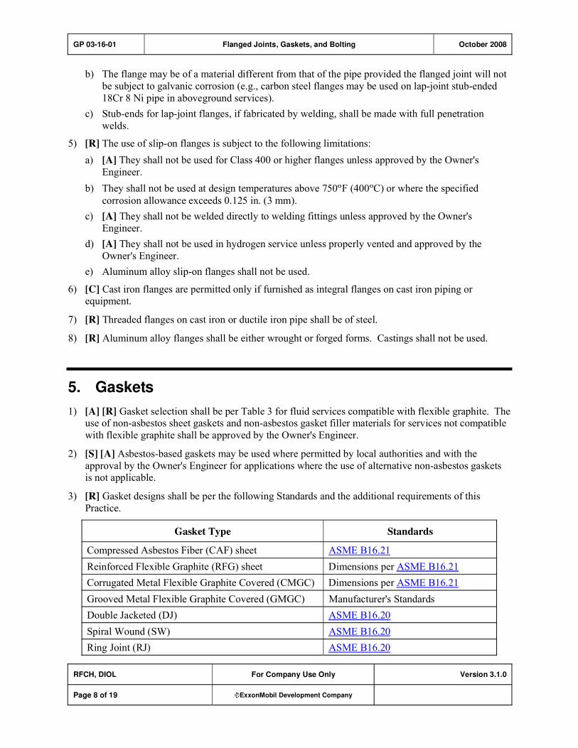
5) [R] The use of slip-on flanges is subject to the following limitations:
a) [A] They shall not be used for Class 400 or higher flanges unless approved by the Owner's
Engineer.
b) They shall not be used at design temperatures above 750 F (400 C) or where the specified
corrosion allowance exceeds 0.125 in. (3 mm).
c) [A] They shall not be welded directly to welding fittings unless approved by the Owner's
Engineer.
d) [A] They shall not be used in hydrogen service unless properly vented and approved by the
Owner's Engineer.
e) Aluminum alloy slip-on flanges shall not be used.
6) [C] Cast iron flanges are permitted only if furnished as integral flanges on cast iron piping or equipment.
7) [R] Threaded flanges on cast iron or ductile iron pipe shall be of steel.
8) [R] Aluminum alloy flanges shall be either wrought or forged forms. Castings shall not be used.
5. Gaskets
1) [A] [R] Gasket selection shall be per Table 3 for fluid services compatible with flexible graphite. The use of non-asbestos sheet gaskets and non-asbestos gasket filler materials for services not compatible
with flexible graphite shall be approved by the Owner's Engineer.
2) [S] [A] Asbestos-based gaskets may be used where permitted by local authorities and with the
approval by the Owner's Engineer for applications where the use of alternative non-asbestos gaskets is not applicable.
3) [R] Gasket designs shall be per the following Standards and the additional requirements of this
Practice.
Gasket Type Standards
Compressed Asbestos Fiber (CAF) sheet ASME B16.21
Reinforced Flexible Graphite (RFG) sheet Dimensions per ASME B16.21
Corrugated Metal Flexible Graphite Covered (CMGC) Dimensions per ASME B16.21
Grooved Metal Flexible Graphite Covered (GMGC) Manufacturer's Standards
Double Jacketed (DJ) ASME B16.20
Spiral Wound (SW) ASME B16.20
Ring Joint (RJ) ASME B16.20
GP 03-16-01 Flanged Joints, Gaskets, and Bolting October 2008
RFCH, DIOL For Company Use Only Version 3.1.0
Page 9 of 19 ExxonMobil Development Company
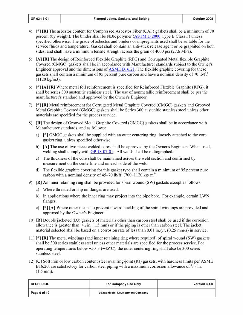
4) [*] [R] The asbestos content for Compressed Asbestos Fiber (CAF) gaskets shall be a minimum of 70
percent (by weight). The binder shall be NBR polymer (ASTM D 2000 Type B Class F) unless
specified otherwise. The grade of asbestos and binders or impregnants used shall be suitable for the service fluids and temperature. Gasket shall contain an anti-stick release agent or be graphited on both
sides, and shall have a minimum tensile strength across the grain of 4000 psi (27.6 MPa).
5) [A] [R] The design of Reinforced Flexible Graphite (RFG) and Corrugated Metal flexible Graphite
Covered (CMGC) gaskets shall be in accordance with Manufacturer standards subject to the Owner's Engineer approval and the dimensions of ASME B16.21. The flexible graphite covering for these
gaskets shall contain a minimum of 95 percent pure carbon and have a nominal density of 70 lb/ft3
(1120 kg/m3).
6) [*] [A] [R] Where metal foil reinforcement is specified for Reinforced Flexible Graphite (RFG), it shall be series 300 austenitic stainless steel. The use of nonmetallic reinforcement shall be per the
manufacturer's standard and approved by the Owner's Engineer.
7) [*] [R] Metal reinforcement for Corrugated Metal Graphite Covered (CMGC) gaskets and Grooved Metal Graphite Covered (GMGC) gaskets shall be Series 300 austenitic stainless steel unless other
materials are specified for the process service.
8) [R] The design of Grooved Metal Graphite Covered (GMGC) gaskets shall be in accordance with
Manufacturer standards, and as follows:
a) [*] GMGC gaskets shall be supplied with an outer centering ring, loosely attached to the core
gasket ring, unless specified otherwise.
b) [A] The use of two piece welded cores shall be approved by the Owner's Engineer. When used, welding shall comply with GP 18-07-01. All welds shall be radiographed.
c) The thickness of the core shall be maintained across the weld section and confirmed by
measurement on the centerline and on each side of the weld.
d) The flexible graphite covering for this gasket type shall contain a minimum of 95 percent pure
carbon with a nominal density of 45�70 lb/ft3 (700�1120 kg/ m3).
9) [R] An inner retaining ring shall be provided for spiral wound (SW) gaskets except as follows:
a) Where threaded or slip on flanges are used.
b) In applications where the inner ring may project into the pipe bore. For example, certain LWN
flanges.
c) [*] [A] Where other means to prevent inward buckling of the spiral windings are provided and
approved by the Owner's Engineer.
10) [R] Double jacketed (DJ) gaskets of materials other than carbon steel shall be used if the corrosion allowance is greater than
1/16 in. (1.5 mm) or if the piping is other than carbon steel. The jacket
material selected shall be based on a corrosion rate of less than 0.01 in./yr. (0.25 mm/a) in service.
11) [*] [R] The metal windings (and inner retaining ring where required) of spiral wound (SW) gaskets shall be 300 series stainless steel unless other materials are specified for the process service. For
operating temperatures below 50 F ( 45 C), the outer centering ring shall also be 300 series stainless steel.
12) [C] Soft iron or low carbon content steel oval ring-joint (RJ) gaskets, with hardness limits per ASME
B16.20, are satisfactory for carbon steel piping with a maximum corrosion allowance of 1/16 in.
(1.5 mm).

GP 03-16-01 Flanged Joints, Gaskets, and Bolting October 2008
RFCH, DIOL For Company Use Only Version 3.1.0
Page 10 of 19 ExxonMobil Development Company
13) [A] [R] Oval Ring-joint (RJ) gaskets of materials other than soft iron or low carbon content steel shall
be used if the corrosion allowance is greater than 1/16 in. (1.5 mm), or if the piping is other than
carbon steel. The ring material selected shall be based on a corrosion rate of less than 0.01 in./yr (0.25 mm/a). The hardness of the ring shall be lower than that of the flange. Where this is not
possible, as in the case of some alloys, the material selection shall be approved by the Owner's
Engineer.
14) [*] [R] Ring joint gaskets shall be of "oval" cross section unless otherwise specified by the Owner's Engineer.
6. Bolting
1) [R] Bolting shall be selected per Table 2.
Table 2: Bolting Requirements
Design Metal
Temperature
Flange
Rating
Bolts Nuts
Deg F Deg C Class Type ASTM Std. Grade ASTM Std. Grade
-40 to 800 -40 to 427 Any Stud ASTM A
193/A 193M
B7(7)
ASTM A
194/A 194M
2H (1)
800 to 1100 427 to 593 Any Stud ASTM A
193/A 193M
B16 ASTM A
194/A 194M
4, 7 (1)
1100 to 1200 593 to 650 Any Stud ASTM A
193/A 193M B5 ASTM A
194/A 194M 3
(1)
1100 to 1500 593 to 815 300 Stud ASTM A
193/A 193M
B8M
Class 1 (2)
ASTM A
194/A 194M
8M
-150 to -20 -101 to -29 Any Stud ASTM A
320/A 320M
L7 (3) (8) ASTM A
194/A 194M
4(1)(6)(3), 7
-325 to 1000 -198 to 537 Any Stud ASTM A
320/A 320M (4)
B8
Class 2 (5) (8)
ASTM A
194/A 194M
8
Notes for Table 2:
(1) Nuts larger than 1/2 in. (12 mm) shall not be machined from bar stock.
(2) Class 1 (low yield) bolts shall not be used for Class 400 or higher flanges nor for flanged joints
using metallic gaskets unless supported by appropriate design calculations per ASME B31.3, Par. 309.2.1.
(3) Test temperature for impact testing of all L7 bolts and Grade 4 nuts, per ASTM A 320/A 320M,
shall be 150 F ( 101 C).

GP 03-16-01 Flanged Joints, Gaskets, and Bolting October 2008
RFCH, DIOL For Company Use Only Version 3.1.0
Page 11 of 19 ExxonMobil Development Company
Notes for Table 2:
(4) ASTM A 193/A 193M Grade B8 Class 2 bolts with ASTM A 194/A 194M Grade 8 nuts may be
used as an alternate. The ASTM A 193/A 193M B8 Class 2 bolts will be marked with the
marking listed in the relevant table (Table 5 of the 2001 edition) and not the grade.
(5) Grade B8 bolts shall be strain hardened (i.e., Class 2 of designated ASTM material standard).
(6) Grade 4 nuts may be used above -50 F (-46 C) without impact testing.
(7) Grade B7 bolts with a diameter of 2.5 inches or less are appropriate for temperatures ranging
from -55 F (-48 C ) to 800 F (427 C).
(8) Diameter limitations apply as specified by ASME B31.3 and ASME B16.5.
2) [A] [R] Ferritic bolting shall be used for all ferritic flanges per the design temperature limits specified
by Section 6, Item (1), unless otherwise approved by the Owner's Engineer.
3) [A] [R] For austenitic stainless steel flanges, the bolting material selection shall be limited to the following:
Bolting Material Flange Design Temperature
Ferritic Steel (Grade B7) Above -40 F up to 1000 F (-40 C to 537 C)
Ferritic Steel (Grade B16) Above -20 F up to 1100 F (-29 C to 593 C)
Austenitic Stainless (Grade B8 Class 2) Below -20 F (-29 C)
Bolting material and design for temperatures outside these limits shall be approved by the Owner's
Engineer.
4) [A] [R] Bolting, including the use of protective coatings, for highly corrosive services such as concentrated acids shall be approved by the Owner's Engineer.
5) [R] Stud bolts shall be threaded full length with continuous threads.
6) [R] Bolts 11/2 in. (38 mm) and larger shall be fitted with hardened washers conforming to ASTM F
436 under each nut. Washers fabricated from AISI 4140 material are acceptable. Surface finish shall be 125 microinch (3.2 micrometers) Ra or smoother on both sides.
7) [*] [R] For bolt diameters 11/2 in. (38 mm) and larger, or when specified, bolt lengths shall be one nut
thickness larger than normally required to accommodate the use of bolt-on type stud tensioners.
8) [S] The use of cadmium coated bolts is not permitted.

GP 03-16-01 Flanged Joints, Gaskets, and Bolting October 2008
RFCH, DIOL For Company Use Only Version 3.1.0
Page 12 of 19 ExxonMobil Development Company
Table 3: Flange Facings and Gaskets
Flange Design Conditions Service Fluid
ASME
Rating Class
Temperature
Range, Deg F (1)
Flange
Facing
Gasket Type
-50 to 750 RF RFG, CMGC(4),
GMGC, or SW (9)
150 (2) and
300
Above 750 to 975 RF SW, DJ, or GMGC
-50 to 975 RF SW or GMGC 400 and 600
Above 975 RJ RJ
-50 to 800 RF SW or GMGC 900
Above 800 RJ RJ
-50 to 800 RF GMGC
Hydrocarbon (3)
1500 and 2500
Any RJ RJ (10)
-50 to 750 RF CMGC(4), GMGC, or
SW (9)
150 (2) and
300
Above 750 to 900 RF SW, DJ, or GMGC
-50 to 900 RF SW, or GMGC 400 and 600
Above 900 RJ RJ
-50 to 800 RF SW, or GMGC 900
Above 800 RJ RJ
-50 to 800 RF GMGC
Hydrogen (4)
and Helium
1500 and 2500
Any RJ RJ (10)
750 and below RF CMGC(4)(11) GMGC, or
SW (9)
150 and 300
Above 750 to 975 RF SW or DJ
975 and below RF SW 400, 600, and 900
Above 975 RJ RJ
Steam and
Steam Condensate
1500 Any RJ RJ (10)
600 and below RF RFG(4)
, CMGC(4)
,
GMGC, or SW (9)
Above 600 to 750 RF CMGC(4), GMGC or
SW
Air or other
Oxidizing Media
150 and 300
Above 750 to 875 RF SW or DJ

GP 03-16-01 Flanged Joints, Gaskets, and Bolting October 2008
RFCH, DIOL For Company Use Only Version 3.1.0
Page 13 of 19 ExxonMobil Development Company
Flange Design Conditions Service Fluid
ASME
Rating Class
Temperature
Range, Deg F (1)
Flange
Facing
Gasket Type
150 or lower Any FF RFG
150 and 300 Any RF CMGC(4)
, GMGC, or SW (9)
400, 600, 900 Any RF SW
Water (5)
including
Boiler Feed
1500 Any RJ RJ (10)
750 and below RF CMGC(4)
,GMGC or SW
Fluid
Catalyst (6)
150 and 300
Above 750 to 875 RF SW or DJ
Toxic Materials (7)
150 and 300 750 and below RF CMGC(4)
, GMGC, or
SW (9)
150 and 300 -250 and above RF CMGC(4)
or GMGC Refrigerant (8)
and
Refrigerated
Hydrocarbons
900 and below
-400 and above RF SW (9) (12)
Legend for Gasket Types:
RFG Nominal 1/16 in. (1.5 mm) thick Reinforced Flexible Graphite Sheet gasket
CMGC Nominal 1/16 in. (1.5 mm) thick Corrugated Metal Graphite Covered gasket
GMGC Grooved Metal Graphite Covered gasket
SW Spiral Wound (flexible graphite filled) gasket
DJ Corrugated Double Jacketed (flexible graphite filled) gasket
RJ Ring Joint gasket
Notes to Table 3:
(1) [A] Gasket design temperature shall be the same as the flange design temperature. The Owner's Engineer shall be consulted for temperatures beyond the range specified.
(2) Includes Vacuum.
(3) Liquid, vapor, or gas, except when in refrigerant service.
(4) [A] The use of CMGC and RFG gaskets in class 300 shall be approved by the Owner's
Engineer.
(5) Excludes seawater or other aqueous solution salts where possible electrochemical reactions
between the graphite and metallic flange (or gasket) components can lead to galvanic
corrosion.

GP 03-16-01 Flanged Joints, Gaskets, and Bolting October 2008
RFCH, DIOL For Company Use Only Version 3.1.0
Page 14 of 19 ExxonMobil Development Company
Notes to Table 3:
(6) In suspension in any medium, unless medium is toxic.
(7) Includes materials such as acids, caustics, phenol, chorine, hydrogen sulfide contained in
solutions or mixtures. Mineral acids, such as sulfuric and nitric acids, not compatible with
graphite are excluded.
(8) Includes propane, ethylene, ammonia, freon, Nitrogen, LNG.
(9) Use of SW gaskets for Class 150 flanges requires review of applied bolt loads for proper
seating of the gasket. A review of applied bolt load is not required where acceptable flange
sealing performance has been demonstrated by past experience or test.
(10) Raised face flanges (RF) and spiral wound (SW) flexible graphite filled gaskets with inner and
outer rings are acceptable up to 800 F (427 C) where the design pressure is below 2700 psig (18600 kPa).
(11) Use of CMGC gaskets for steam services is limited to Class 150.
(12) [A] Use of spiral wound (SW) gaskets for aluminum alloy flanges requires approval by the
Owner's Engineer.
GP 03-16-01 Flanged Joints, Gaskets, and Bolting October 2008
RFCH, DIOL For Company Use Only Version 3.1.0
Page 15 of 19 ExxonMobil Development Company
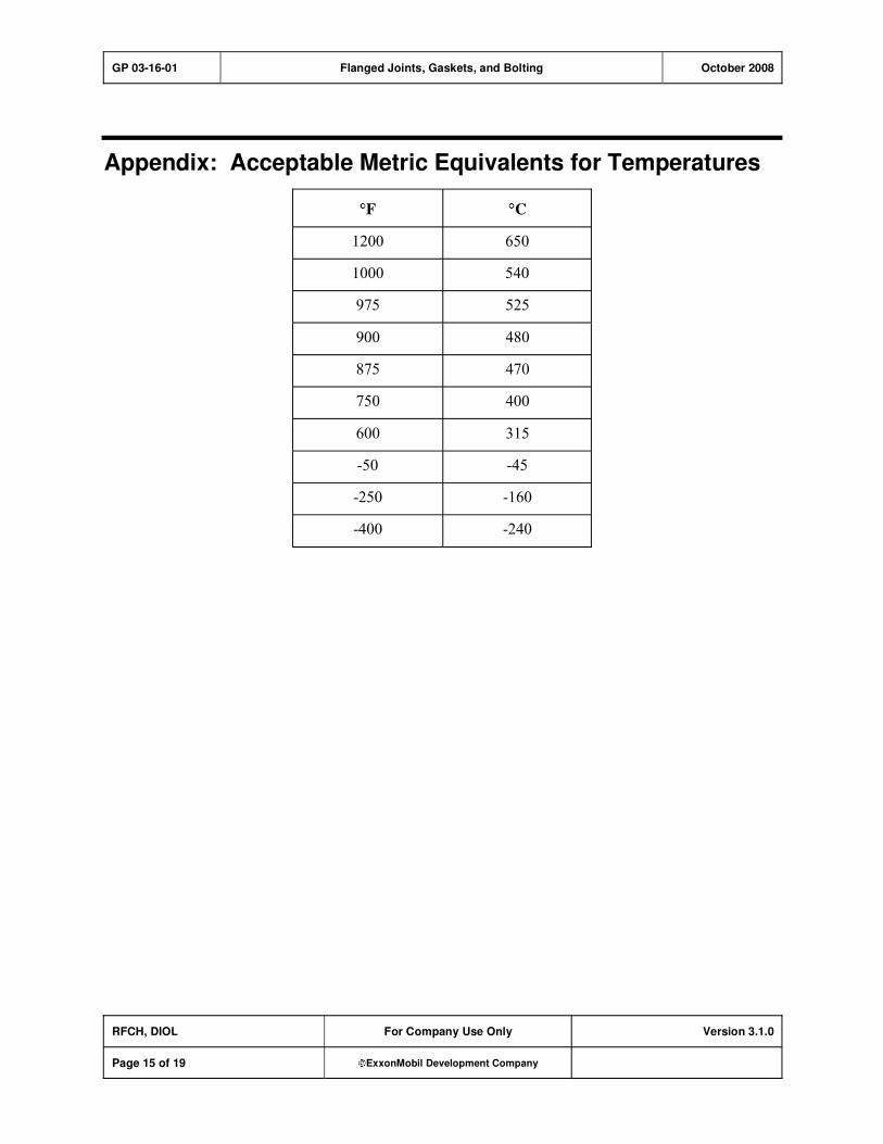
Appendix: Acceptable Metric Equivalents for Temperatures
F C
1200 650
1000 540
975 525
900 480
875 470
750 400
600 315
-50 -45
-250 -160
-400 -240
GP 03-16-01 Flanged Joints, Gaskets, and Bolting October 2008
RFCH, DIOL For Company Use Only Version 3.1.0
Page 16 of 19 ExxonMobil Development Company
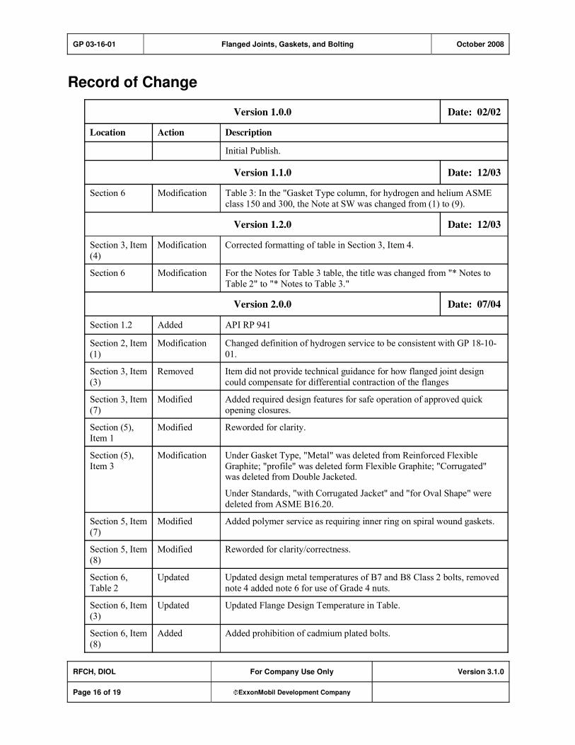
Record of Change
Version 1.0.0 Date: 02/02
Location Action Description
Initial Publish.
Version 1.1.0 Date: 12/03
Section 6 Modification Table 3: In the "Gasket Type column, for hydrogen and helium ASME
class 150 and 300, the Note at SW was changed from (1) to (9).
Version 1.2.0 Date: 12/03
Section 3, Item
(4)
Modification Corrected formatting of table in Section 3, Item 4.
Section 6 Modification For the Notes for Table 3 table, the title was changed from "* Notes to
Table 2" to "* Notes to Table 3."
Version 2.0.0 Date: 07/04
Section 1.2 Added API RP 941
Section 2, Item
(1)
Modification Changed definition of hydrogen service to be consistent with GP 18-10-
01.
Section 3, Item
(3)
Removed Item did not provide technical guidance for how flanged joint design
could compensate for differential contraction of the flanges
Section 3, Item
(7)
Modified Added required design features for safe operation of approved quick
opening closures.
Section (5),
Item 1
Modified Reworded for clarity.
Section (5),
Item 3
Modification Under Gasket Type, "Metal" was deleted from Reinforced Flexible
Graphite; "profile" was deleted form Flexible Graphite; "Corrugated" was deleted from Double Jacketed.
Under Standards, "with Corrugated Jacket" and "for Oval Shape" were
deleted from ASME B16.20.
Section 5, Item
(7)
Modified Added polymer service as requiring inner ring on spiral wound gaskets.
Section 5, Item
(8)
Modified Reworded for clarity/correctness.
Section 6,
Table 2
Updated Updated design metal temperatures of B7 and B8 Class 2 bolts, removed
note 4 added note 6 for use of Grade 4 nuts.
Section 6, Item
(3)
Updated Updated Flange Design Temperature in Table.
Section 6, Item
(8)
Added Added prohibition of cadmium plated bolts.
GP 03-16-01 Flanged Joints, Gaskets, and Bolting October 2008
RFCH, DIOL For Company Use Only Version 3.1.0
Page 17 of 19 ExxonMobil Development Company
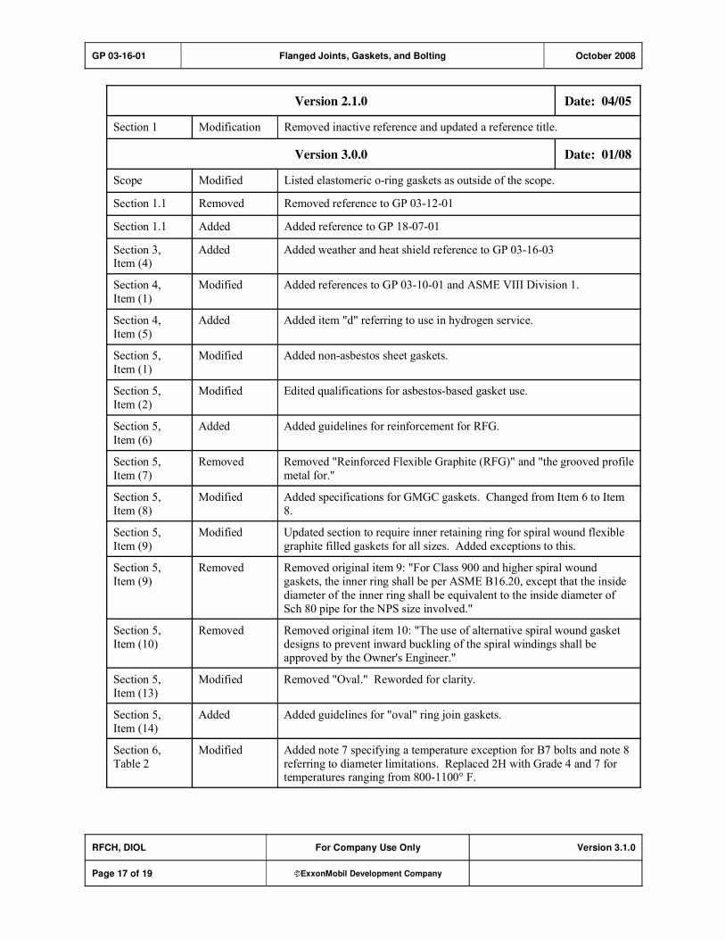
Version 2.1.0 Date: 04/05
Section 1 Modification Removed inactive reference and updated a reference title.
Version 3.0.0 Date: 01/08
Scope Modified Listed elastomeric o-ring gaskets as outside of the scope.
Section 1.1 Removed Removed reference to GP 03-12-01
Section 1.1 Added Added reference to GP 18-07-01
Section 3, Item (4)
Added Added weather and heat shield reference to GP 03-16-03
Section 4,
Item (1)
Modified Added references to GP 03-10-01 and ASME VIII Division 1.
Section 4,
Item (5)
Added Added item "d" referring to use in hydrogen service.
Section 5,
Item (1)
Modified Added non-asbestos sheet gaskets.
Section 5,
Item (2)
Modified Edited qualifications for asbestos-based gasket use.
Section 5,
Item (6)
Added Added guidelines for reinforcement for RFG.
Section 5,
Item (7)
Removed Removed "Reinforced Flexible Graphite (RFG)" and "the grooved profile
metal for."
Section 5,
Item (8)
Modified Added specifications for GMGC gaskets. Changed from Item 6 to Item
8.
Section 5,
Item (9)
Modified Updated section to require inner retaining ring for spiral wound flexible
graphite filled gaskets for all sizes. Added exceptions to this.
Section 5,
Item (9)
Removed Removed original item 9: "For Class 900 and higher spiral wound
gaskets, the inner ring shall be per ASME B16.20, except that the inside
diameter of the inner ring shall be equivalent to the inside diameter of
Sch 80 pipe for the NPS size involved."
Section 5,
Item (10)
Removed Removed original item 10: "The use of alternative spiral wound gasket
designs to prevent inward buckling of the spiral windings shall be
approved by the Owner's Engineer."
Section 5,
Item (13)
Modified Removed "Oval." Reworded for clarity.
Section 5,
Item (14)
Added Added guidelines for "oval" ring join gaskets.
Section 6,
Table 2
Modified Added note 7 specifying a temperature exception for B7 bolts and note 8
referring to diameter limitations. Replaced 2H with Grade 4 and 7 for temperatures ranging from 800-1100° F.
GP 03-16-01 Flanged Joints, Gaskets, and Bolting October 2008
RFCH, DIOL For Company Use Only Version 3.1.0
Page 18 of 19 ExxonMobil Development Company
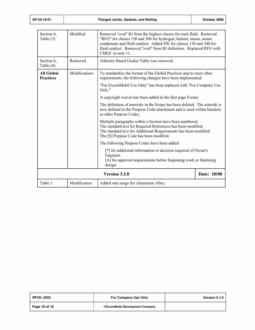
Section 6,
Table (3)
Modified Removed "oval" RJ from the highest classes for each fluid. Removed
"RFG" for classes 150 and 300 for hydrogen, helium, steam, steam
condensate and fluid catalyst. Added SW for classes 150 and 300 for
fluid catalyst. Removed "oval" from RJ definition. Replaced RFG with
CMGC in note 11.
Section 6, Table (4)
Removed Asbestos Based Gasket Table was removed.
All Global
Practices
Modifications To standardize the format of the Global Practices and to meet other requirements, the following changes have been implemented:
"For ExxonMobil Use Only" has been replaced with "For Company Use
Only."
A copyright waiver has been added in the first page Footer.
The definition of asterisks in the Scope has been deleted. The asterisk is
now defined in the Purpose Code attachment and is used within brackets
as other Purpose Codes.
Multiple paragraphs within a Section have been numbered.
The standard text for Required References has been modified.
The standard text for Additional Requirements has been modified.
The [S] Purpose Code has been modified.
The following Purpose Codes have been added:
[*] for additional information or decision required of Owner's
Engineer.
[A] for approval requirements before beginning work or finalizing
design.
Version 3.1.0 Date: 10/08
Table 1 Modification Added mm range for Aluminum Alloy.

GP 03-16-01 Flanged Joints, Gaskets, and Bolting October 2008
RFCH, DIOL For Company Use Only Version 3.1.0
Page 19 of 19 ExxonMobil Development Company
Attachment: Purpose Code Definitions
Code Description
* Assigned to paragraphs that require the Owner's Engineer to provide additional information or
make a decision.
A Assigned to paragraphs that require approval from the Owner's Engineer before the work may
proceed or the design is finalized.
C Assigned to paragraphs whose primary purpose is reduced costs. Reduced cost in this context
refers to initial investment cost and does not include life cycle cost considerations. Life cycle
cost considerations are captured under reliability, maintainability, or operability purpose codes.
E Assigned to paragraphs whose primary purpose is driven by environmental considerations. Environmental considerations typically include specifications intended to protect against
emissions/leakage to the air, water, and/or soil. Deviations from the specifications contained
in such paragraphs require formal review and approval according to local environmental policy.
I Assigned to paragraphs that provide only clarifying information, such as Scope statements,
definitions of terms, etc.
M Assigned to paragraphs whose primary purpose is to provide for maintainability of equipment or systems. Maintainability provisions are those that facilitate the performance of maintenance
on equipment/systems either during downtimes or during onstream operations.
O Assigned to paragraphs whose primary purpose is to assure operability of equipment or
systems. Operability is the ability of the equipment/system to perform satisfactorily even though conditions are off-design, such as during start-ups, process swings, subcomponent
malfunction, etc.
R Assigned to paragraphs whose primary purpose is to improve or assure the reliability of
equipment or systems. Reliability is a measure of the ability of equipment/systems to operate without malfunction or failure between planned maintenance interventions.
S Assigned to paragraphs containing specifications/guidance where the primary purpose is the
avoidance of incidents impacting personnel safety, operational safety, and the public in general and/or involving responses to emergency situations. Any deviation from the specifications
contained in such designated paragraphs requires formal review and approval according to
local safety policy.
Personnel Safety: Refers to incident-related personnel injuries or illness, e.g., burns, cuts, abrasions, inhalation of or exposure to dangerous substances, etc., that
could result in medical treatment, restricted work, lost-time incidents, or
fatalities.
Operational
Safety:
Refers to the prevention and control of process releases, fires, and/or
explosions that could result in damage to equipment, process disruption,
or personnel injury or illness.

GP 03-18-01 Piping Fabrication Shop or Field August 2008
Refining/Chemicals, Downstream Imperial Oil
For Company Use Only Version 3.1.0
Page 1 of 22 ExxonMobil Development Company
Copyright Waiver ExxonMobil Development Company and ExxonMobil Pipeline Company hereby license the use of ExxonMobil Engineering Practices System (EMEPS) Global Practices (GPs) for use by any ExxonMobil division, subsidiary, or more-than-50%-owned affiliate. The GPs may be downloaded and modified as necessary for project and affiliate use. Written permission from ExxonMobil Development Company or ExxonMobil Pipeline Company is not required. However, any modified GPs must be renumbered to a project-specific or affiliate-specific number to distinguish them from the GPs on the EMEPS web site. ExxonMobil operated joint ventures may utilize GPs to create project-specific or location-specific specifications. It is the responsibility of individual affiliate or joint venture to ensure that the use of GPs and their derivatives is limited to joint venture related business and not disclosed or used outside the JV without appropriate EM management approval.
Piping Fabrication Shop or Field
GP 03-18-01
Scope
[I] This Global Practice (GP) covers the fabrication, inspection, and shop testing of piping.
GP 03-18-01 Piping Fabrication Shop or Field August 2008
RFCH, DIOL For Company Use Only Version 3.1.0
Page 2 of 22 ExxonMobil Development Company
Table of Contents
1. Required References ............................................................................................ 4
1.1. Global Practices–ExxonMobil Engineering Practices ................................... 4
1.2. ASME–American Society of Mechanical Engineers ..................................... 4
2. Additional Requirements...................................................................................... 4
2.1. Global Practices–ExxonMobil Engineering Practices ................................... 4
2.2. API–American Petroleum Institute................................................................ 5
2.3. ASME–American Society of Mechanical Engineers ..................................... 5
2.4. AWS–American Welding Society.................................................................. 5
2.5. CEN–European Committee for Standardization ........................................... 5
2.6. DIN–Deutsches Institut fur Normung ............................................................ 5
2.7. JIS–Japanese Industrial Standards .............................................................. 5
2.8. PFI–Pipe Fabrication Institute ...................................................................... 5
3. Definitions.............................................................................................................. 6
4. Small Piping Documentation................................................................................ 7
5. Attachment Materials ............................................................................................ 7
6. Bends, Miter Bends, and Elbows......................................................................... 7
7. Dimensional Tolerances ....................................................................................... 8
8. Location of Connections ...................................................................................... 8
9. Branch Connections Larger Than NPS 2 (50 mm).............................................. 8
10. Small Piping Connections .................................................................................... 9
11. Bracing of Pipe Connections Less than NPS 2 (50 mm).................................... 9
12. Seal Welding Threaded Connections ................................................................ 11
13. Valves, Flanges, and Joints ............................................................................... 12
14. Welding Joints..................................................................................................... 13
15. Additional Requirements for Cement-Lined Carbon Steel Pipe and Fittings 13
16. Heat Treatment .................................................................................................... 14
GP 03-18-01 Piping Fabrication Shop or Field August 2008
RFCH, DIOL For Company Use Only Version 3.1.0
Page 3 of 22 ExxonMobil Development Company
17. Inspection and Testing ....................................................................................... 15
17.1. Visual Examination ..................................................................................... 15
17.2. Radiographic Examination.......................................................................... 15
17.3. Ultrasonic Examination............................................................................... 17
17.4. Magnetic Particle Examination ................................................................... 17
17.5. Liquid Penetrant Examination..................................................................... 18
17.6. Shop Pressure Testing ............................................................................... 18
18. Preparation for Shipment ................................................................................... 18
Record of Change ....................................................................................................... 19
Attachment: Purpose Code Definitions.................................................................... 22
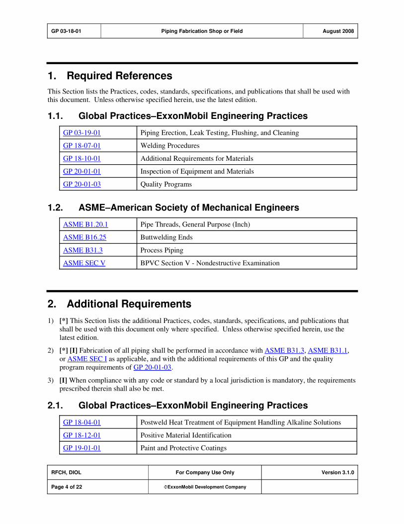
GP 03-18-01 Piping Fabrication Shop or Field August 2008
RFCH, DIOL For Company Use Only Version 3.1.0
Page 4 of 22 ExxonMobil Development Company
1. Required References
This Section lists the Practices, codes, standards, specifications, and publications that shall be used with this document. Unless otherwise specified herein, use the latest edition.
1.1. Global Practices–ExxonMobil Engineering Practices
GP 03-19-01 Piping Erection, Leak Testing, Flushing, and Cleaning
GP 18-07-01 Welding Procedures
GP 18-10-01 Additional Requirements for Materials
GP 20-01-01 Inspection of Equipment and Materials
GP 20-01-03 Quality Programs
1.2. ASME–American Society of Mechanical Engineers
ASME B1.20.1 Pipe Threads, General Purpose (Inch)
ASME B16.25 Buttwelding Ends
ASME B31.3 Process Piping
ASME SEC V BPVC Section V - Nondestructive Examination
2. Additional Requirements
1) [*] This Section lists the additional Practices, codes, standards, specifications, and publications that
shall be used with this document only where specified. Unless otherwise specified herein, use the
latest edition.
2) [*] [I] Fabrication of all piping shall be performed in accordance with ASME B31.3, ASME B31.1,
or ASME SEC I as applicable, and with the additional requirements of this GP and the quality
program requirements of GP 20-01-03.
3) [I] When compliance with any code or standard by a local jurisdiction is mandatory, the requirements prescribed therein shall also be met.
2.1. Global Practices–ExxonMobil Engineering Practices
GP 18-04-01 Postweld Heat Treatment of Equipment Handling Alkaline Solutions
GP 18-12-01 Positive Material Identification
GP 19-01-01 Paint and Protective Coatings
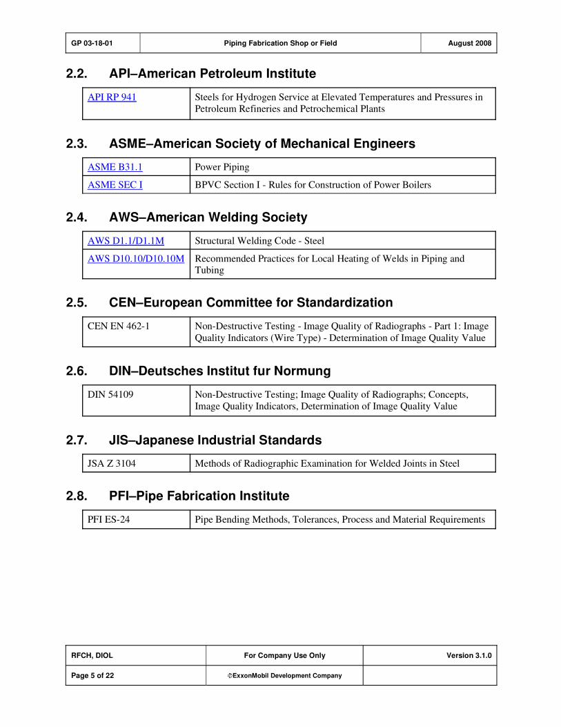
GP 03-18-01 Piping Fabrication Shop or Field August 2008
RFCH, DIOL For Company Use Only Version 3.1.0
Page 5 of 22 ExxonMobil Development Company
2.2. API–American Petroleum Institute
API RP 941 Steels for Hydrogen Service at Elevated Temperatures and Pressures in
Petroleum Refineries and Petrochemical Plants
2.3. ASME–American Society of Mechanical Engineers
ASME B31.1 Power Piping
ASME SEC I BPVC Section I - Rules for Construction of Power Boilers
2.4. AWS–American Welding Society
AWS D1.1/D1.1M Structural Welding Code - Steel
AWS D10.10/D10.10M Recommended Practices for Local Heating of Welds in Piping and Tubing
2.5. CEN–European Committee for Standardization
CEN EN 462-1 Non-Destructive Testing - Image Quality of Radiographs - Part 1: Image
Quality Indicators (Wire Type) - Determination of Image Quality Value
2.6. DIN–Deutsches Institut fur Normung
DIN 54109 Non-Destructive Testing; Image Quality of Radiographs; Concepts,
Image Quality Indicators, Determination of Image Quality Value
2.7. JIS–Japanese Industrial Standards
JSA Z 3104 Methods of Radiographic Examination for Welded Joints in Steel
2.8. PFI–Pipe Fabrication Institute
PFI ES-24 Pipe Bending Methods, Tolerances, Process and Material Requirements
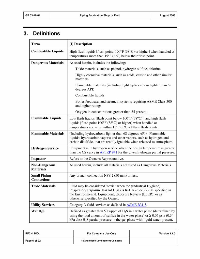
GP 03-18-01 Piping Fabrication Shop or Field August 2008
RFCH, DIOL For Company Use Only Version 3.1.0
Page 6 of 22 ExxonMobil Development Company
3. Definitions
Term [I] Description
Combustible Liquids High flash liquids [flash points 100 F (38 C) or higher] when handled at
temperatures more than 15 F (8 C) below their flash point.
As used herein, includes the following:
Toxic materials, such as phenol, hydrogen sulfide, chlorine
Highly corrosive materials, such as acids, caustic and other similar materials
Flammable materials (including light hydrocarbons lighter than 68
degrees API)
Combustible liquids
Boiler feedwater and steam, in systems requiring ASME Class 300
and higher ratings
Dangerous Materials
Oxygen in concentrations greater than 35 percent
Flammable Liquids Low flash liquids [flash point below 100 F (38 C)], and high flash
liquids [flash point 100 F (38 C) or higher] when handled at
temperatures above or within 15 F (8 C) of their flash points.
Flammable Materials (Including hydrocarbons lighter than 68 degrees API). Flammable
liquids; hydrocarbon vapors; and other vapors, such as hydrogen and carbon disulfide, that are readily ignitable when released to atmosphere.
Hydrogen Service Equipment is in hydrogen service when the design temperature is greater
than the CS curve in API RP 941 for the given hydrogen partial pressure.
Inspector Refers to the Owner's Representative.
Non-Dangerous
Materials
As used herein, include all materials not listed as Dangerous Materials.
Small Piping
Connections
Any branch connection NPS 2 (50 mm) or less.
Toxic Materials Fluid may be considered "toxic" when the (Industrial Hygiene) Respiratory Exposure Hazard Class is R-1, R-2, or R-3, as specified in
the Environmental, Equipment, Exposure Review (EEER), or as
otherwise specified by the Owner.
Utility Services Category D fluid services as defined in ASME B31.3.
Wet H2S Defined as greater than 50 wppm of H2S in a water phase (determined by
using the total amount of sulfide in the water phase) or 0.05 psia (0.34 kPa abs) H2S partial pressure in the gas phase with liquid water present.

GP 03-18-01 Piping Fabrication Shop or Field August 2008
RFCH, DIOL For Company Use Only Version 3.1.0
Page 7 of 22 ExxonMobil Development Company
4. Small Piping Documentation
[I] The following information for small piping connections shall be shown on the Engineering Drawings:
1) Specific location and orientation of small piping connections.
2) Connection size and schedule.
3) Valve or fitting type.
4) Designation of connections to be gusseted, and specifications to be used for gussets.
5) Special welding requirements.
6) Temporary valves and nipples that are used only during pressure testing shall be indicated on the drawings.
5. Attachment Materials
[A] [R] Unless otherwise specified or approved by the Owner's Engineer, lugs, brackets, insulation supports, or other attachments that must be welded to piping shall be of similar nominal chemical
composition as the piping component to which they are attached, except for gusseting of small branch
connections. P1 material may be used for attachments to P3 through P5 materials that are not in hydrogen
service.
6. Bends, Miter Bends, and Elbows
1) [R] Pipe bends shall comply with the following requirements:
a) Bending shall be in accordance with PFI ES-24.
b) [A] The centerline radius of pipe bends shall be equal to at least three times the nominal pipe diameter. Proposals to use smaller radius pipe bends shall be submitted to Purchaser for approval
by the Owner's Engineer.
2) [R] Miter bends may be used where the pipe diameter exceeds NPS 12 (300 mm) and shall comply with the following:
a) Bends exceeding 45 degrees shall be at least three-piece (two miter cuts), with not less than four times the pipe wall thickness between the centerlines of the welds at the crotch, or 1 in. (25 mm),
whichever is greater.
b) Bends shall have a centerline radius at least equal to the nominal pipe size.
c) The maximum miter angle (half the change of directions) shall be 221/2 degrees up to 200 psig
(1380 kPa) design pressure, 15 degrees up to 400 psig (2760 kPa), and 111/4 degrees over 400
psig (2760 kPa).
3) [A] [R] Buttwelding elbows shall be of the long radius type, unless otherwise approved by the Owner's Engineer.
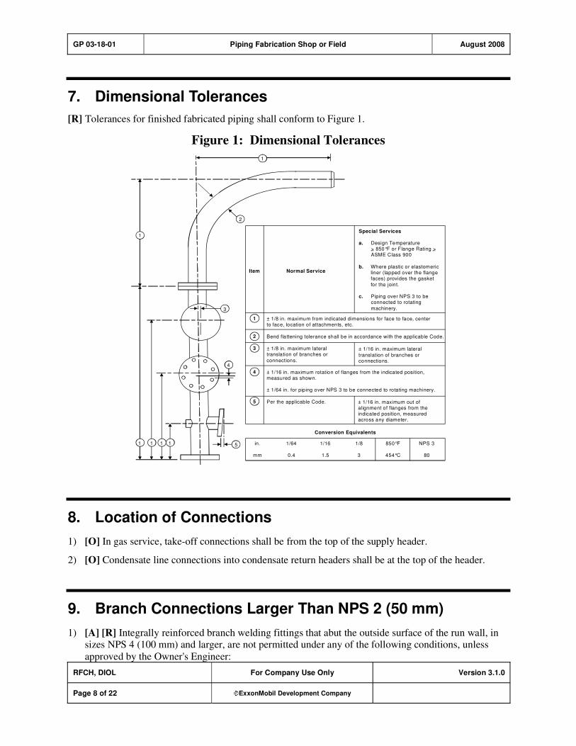
GP 03-18-01 Piping Fabrication Shop or Field August 2008
RFCH, DIOL For Company Use Only Version 3.1.0
Page 8 of 22 ExxonMobil Development Company
7. Dimensional Tolerances
[R] Tolerances for finished fabricated piping shall conform to Figure 1.
Figure 1: Dimensional Tolerances
1
1
3
4
51 1 1 1
2
Conversion Equivalents
in. 1/64 1/16 1/8 850°F NPS 3
mm 0.4 1.5 3 454°C 80
Special Services
a. Design Temperature> 850°F or Flange Rating >ASME Class 900
b. Where plastic or elastomericliner (lapped over the flangefaces) provides the gasket
for the joint.
c. Piping over NPS 3 to beconnected to rotating
machinery.
Item
1
2
3
4
5
Normal Service
± 1/8 in. maximum from indicated dimensions for face to face, centerto face, location of attachments, etc.
Bend flattening tolerance shall be in accordance with the applicable Code.
± 1/8 in. maximum lateraltranslation of branches or
connections.
± 1/16 in. maximum rotation of flanges from the indicated position,measured as shown.
± 1/64 in. for piping over NPS 3 to be connected to rotating machinery.
Per the applicable Code.
± 1/16 in. maximum lateral
translation of branches orconnections.
± 1/16 in. maximum out ofalignment of flanges from theindicated position, measuredacross any diameter.
– –
8. Location of Connections
1) [O] In gas service, take-off connections shall be from the top of the supply header.
2) [O] Condensate line connections into condensate return headers shall be at the top of the header.
9. Branch Connections Larger Than NPS 2 (50 mm)
1) [A] [R] Integrally reinforced branch welding fittings that abut the outside surface of the run wall, in sizes NPS 4 (100 mm) and larger, are not permitted under any of the following conditions, unless
approved by the Owner's Engineer:

GP 03-18-01 Piping Fabrication Shop or Field August 2008
RFCH, DIOL For Company Use Only Version 3.1.0
Page 9 of 22 ExxonMobil Development Company
a) The d/D ratio (branch NPS/run NPS) exceeds 0.8.
b) The run piping wall thickness is less than standard schedule.
c) The run piping wall thickness is less than 0.75 in. (19 mm) where outside diameter exceeds 36 in.
(900 mm).
2) [R] Welded support pads and pad-reinforced branch connections are not permitted whenever the
piping design temperature is 800 F (427 C) or greater.
10. Small Piping Connections
1) [R] The minimum schedule of nipples that are used for branch connections NPS 2 (50 mm) or smaller
shall be as follows:
Material NPS 11/2 (40 mm) NPS 2 (50 mm)
Carbon and low alloy steel 160 80
Carbon and low alloy steel in Utility Services 80 80
Stainless and other high alloy steel 80S 40S
Exception: This requirement does not apply for connections to rotating equipment.
2) [R] Nipples that are threaded over their entire length shall not be used.
3) [S] [*] Regarding vibrating service or dangerous materials service: a block valve shall be provided
for the purpose of isolating all piping connections NPS 11/2 (40 mm) to main headers of any size.
Exception: Control valve stations are excluded from this requirement.
4) [*] [R] When a valve is provided for the purpose of isolating piping connections NPS 11/2 (40 mm),
the valve centerline shall be located within 9 in. (225 mm) of the branch connection, measured along the branch pipe axis.
[A] In cases where adherence to the 9 in. (225 mm) dimension (pipe wall to valve centerline) is not
practicable, the Owner's Engineer shall approve any deviations.
11. Bracing of Pipe Connections Less than NPS 2 (50 mm)
1) [S] [R] Piping connections NPS 11/2 (40 mm) that connect to a pipe two or more sizes larger shall
be braced for the following applications:
a) For both vibrating and non-vibrating services, bracing is required for piping connections NPS
11/2 (40 mm) that are fabricated using a nipple welded directly to the run pipe without the use of a
reinforced fitting, except for Category D fluid services.
b) As required for vibrating services per Table 1 below:
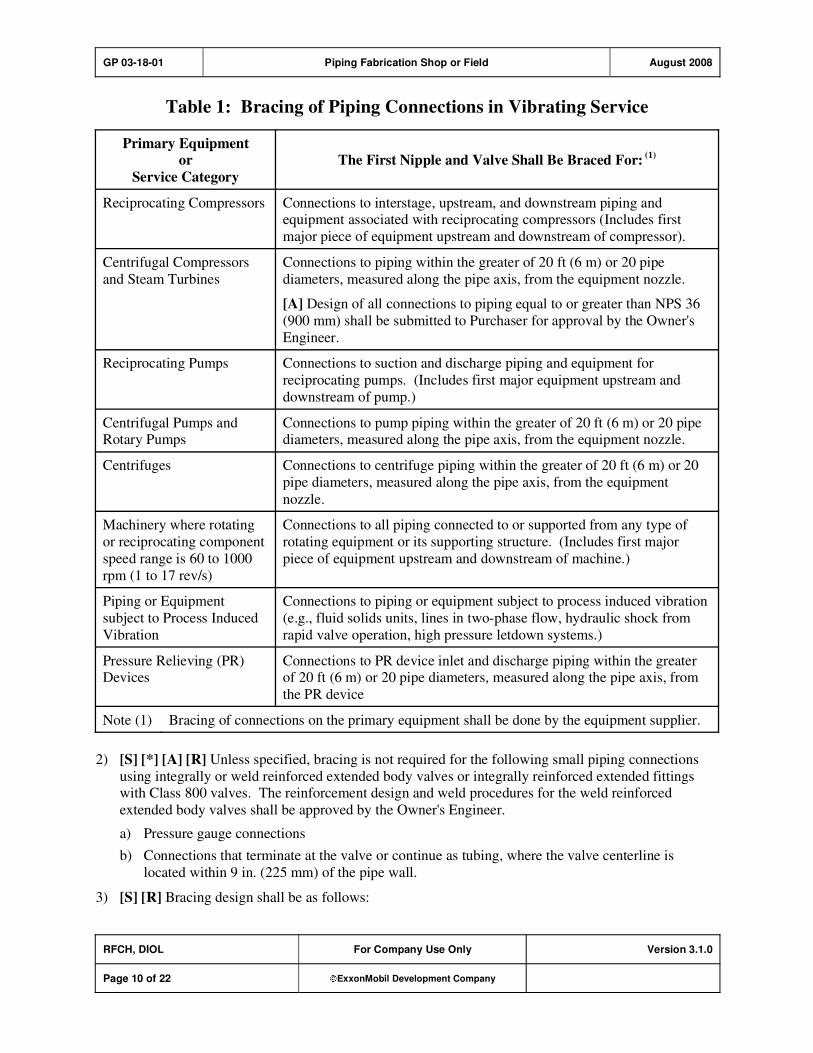
GP 03-18-01 Piping Fabrication Shop or Field August 2008
RFCH, DIOL For Company Use Only Version 3.1.0
Page 10 of 22 ExxonMobil Development Company
Table 1: Bracing of Piping Connections in Vibrating Service
Primary Equipment
or
Service Category
The First Nipple and Valve Shall Be Braced For: (1)
Reciprocating Compressors Connections to interstage, upstream, and downstream piping and equipment associated with reciprocating compressors (Includes first
major piece of equipment upstream and downstream of compressor).
Centrifugal Compressors
and Steam Turbines
Connections to piping within the greater of 20 ft (6 m) or 20 pipe
diameters, measured along the pipe axis, from the equipment nozzle.
[A] Design of all connections to piping equal to or greater than NPS 36
(900 mm) shall be submitted to Purchaser for approval by the Owner's
Engineer.
Reciprocating Pumps Connections to suction and discharge piping and equipment for
reciprocating pumps. (Includes first major equipment upstream and
downstream of pump.)
Centrifugal Pumps and Rotary Pumps
Connections to pump piping within the greater of 20 ft (6 m) or 20 pipe diameters, measured along the pipe axis, from the equipment nozzle.
Centrifuges Connections to centrifuge piping within the greater of 20 ft (6 m) or 20
pipe diameters, measured along the pipe axis, from the equipment
nozzle.
Machinery where rotating
or reciprocating component
speed range is 60 to 1000
rpm (1 to 17 rev/s)
Connections to all piping connected to or supported from any type of
rotating equipment or its supporting structure. (Includes first major
piece of equipment upstream and downstream of machine.)
Piping or Equipment
subject to Process Induced
Vibration
Connections to piping or equipment subject to process induced vibration
(e.g., fluid solids units, lines in two-phase flow, hydraulic shock from
rapid valve operation, high pressure letdown systems.)
Pressure Relieving (PR) Devices
Connections to PR device inlet and discharge piping within the greater of 20 ft (6 m) or 20 pipe diameters, measured along the pipe axis, from
the PR device
Note (1) Bracing of connections on the primary equipment shall be done by the equipment supplier.
2) [S] [*] [A] [R] Unless specified, bracing is not required for the following small piping connections
using integrally or weld reinforced extended body valves or integrally reinforced extended fittings with Class 800 valves. The reinforcement design and weld procedures for the weld reinforced
extended body valves shall be approved by the Owner's Engineer.
a) Pressure gauge connections
b) Connections that terminate at the valve or continue as tubing, where the valve centerline is
located within 9 in. (225 mm) of the pipe wall.
3) [S] [R] Bracing design shall be as follows:

GP 03-18-01 Piping Fabrication Shop or Field August 2008
RFCH, DIOL For Company Use Only Version 3.1.0
Page 11 of 22 ExxonMobil Development Company
a) Material for welded gussets shall be of the same nominal chemical composition as the connected
parts except that carbon steel may be used for gusseting P-1, P-3, P-4, and P-5 materials.
b) Connections shall be braced in two planes with gussets having a minimum thickness of 3/16 in.
(5 mm) and a minimum width of 3/4 in. (19 mm), as shown in Figure 2.
Figure 2: Bracing Design
Alternatively, a single structural 90 degree angle (1 in. x 1 in.) may be used as bracing in one
plane, for piping NPS 6 (150 mm) and smaller.
c) [A] In cases where post-weld heat treatment (PWHT) of structural attachment welds to a pressure boundary is required, gusset stubs (or pads) may be welded to the component prior to PWHT, and
then may be used to permit later gusset-to-stub (or pad) attachment without PWHT. Proposals to
use special welding procedures in lieu of PWHT shall be submitted to Purchaser for approval by
the Owner's Engineer.
d) [A] Proposals to use clamped or bolted gusset designs shall be submitted to Purchaser for
approval by the Owner's Engineer.
4) [A] [R] Bracing design for piping connections NPS 11/2 (40 mm) requiring double block valves
shall be submitted to Purchaser for approval by the Owner's Engineer.
5) [*] [A] [R] Unless otherwise specified, all small piping connections in services that are ASME Class
900 and above shall be braced. The bracing design shall be submitted to Purchaser for Owner's
Engineer approval.
12. Seal Welding Threaded Connections
1) [S] [R] All threaded piping connections including threaded thermowells shall be seal welded.
However, seal welding is not necessary for the following:
a) Category D fluid services as defined in ASME B31.3.

GP 03-18-01 Piping Fabrication Shop or Field August 2008
RFCH, DIOL For Company Use Only Version 3.1.0
Page 12 of 22 ExxonMobil Development Company
b) [*] Instruments or piping components that require periodic removal for maintenance.
c) Union ring threads.
d) [*] Plugs and caps for drain and vent valves. Plugs and caps for drain and vent valves that are
used only for hydrostatic testing and are in dangerous materials service shall be seal welded.
e) [*] Miscellaneous other connections identified by the Owner's Engineer.
2) [R] If piping assemblies will be PWHT, seal welding shall be given the necessary heat treatment as
well. However P-1, P-3, P-4, P-5A, and P-9 materials may be seal welded without subsequent PWHT provided all of the following requirements are met:
a) The minimum preheat meets either the "required" or the "recommended" preheat listed in ASME
B31.3.
b) A temper beading technique is employed for all materials except P-1. P-1 material in wet H2S
service requires multi-pass welds per GP 18-10-01.
c) The material is not in alkaline service as defined in GP 18-04-01.
d) Low hydrogen electrodes or welding processes are used.
e) For all alloy steels, either low carbon electrodes with matching chemistry (i.e., E8018-B2L) or
high nickel electrodes (i.e., ENiCrFe-3) are selected.
f) P4 and P5A materials are NOT in hydrogen service.
3) [S] [R] Connections requiring seal welding shall be made without the use of sealing (anti-seize) compound or PTFE tape. All cutting oil shall be removed prior to assembly. After the joint has been
tightened to normal thread engagement per ASME B1.20.1 (hand-tight to 41/2–5 threads), seal
welding shall cover all exposed threads. A minimum of two weld passes is required.
13. Valves, Flanges, and Joints
1) [R] Welding is not permitted on valves equipped with soft seats, unless the seats have been removed
or precautions recommended by the valve manufacturer have been taken to prevent damage to the soft
seats.
2) [R] Taper pipe threads (NPT) per ASME B1.20.1 shall be used for all threaded pipe joints, including thermowell nozzles.
3) [R] Slip-on flanges shall be positioned such that the distance from the face of the flange to the pipe
end is equal to the nominal pipe wall thickness, plus 1/8 in. (3 mm).
4) [M] Flange bolt holes shall straddle the established centerlines (horizontal, vertical, or layout
centerlines), except when required for matching orientation at equipment flanges.
5) [R] Stub-ends for lap-joint flanges, if fabricated by welding, shall be made with complete penetration welds.
6) [S] Pipe unions between process vessels, lines, or equipment and the first block valve are prohibited.
7) [A] [R] The use of proprietary type piping joints shall be approved by the Owner's Engineer.
8) [A] [R] Drip rings (bleed rings) shall not be used unless approved by the Owner's Engineer.

GP 03-18-01 Piping Fabrication Shop or Field August 2008
RFCH, DIOL For Company Use Only Version 3.1.0
Page 13 of 22 ExxonMobil Development Company
14. Welding Joints
1) [R] Welding shall be completed per GP 18-07-01.
2) [*] [R] Unless otherwise required by the piping material or welding processes to be used, welding ends shall be prepared per ASME B16.25.
3) [R] Radial misalignment at the joining ends of piping components shall be limited to 1/8 in. (3 mm) or
1/4 of the pipe wall thickness, whichever is less.
4) Internal radial misalignment exceeding 1/16 in. (1.5 mm) shall be taper trimmed such that the
adjoining internal surfaces are flush. However, the resulting thickness of the welded joint shall not be less than the minimum design thickness plus corrosion allowance.
5) [R] Minimum spacing of girth butt welds shall be as follows. The clear distance between the edges of
adjacent girth butt welds shall not be less than four times the pipe wall thickness, or 1 in. (25 mm), whichever is greater.
6) [A] [R] Minimum spacing of branch connections shall be as follows. The clear distance between the
edges of attachment welds for adjacent branch connections or reinforcement pads shall not be less
than four times the thickness of the run wall, or 1 in. (25 mm), whichever is greater. The Owner's Engineer shall approve deviations from this spacing requirement.
7) [M] Backing rings may be used only for the following applications:
a) For piping under the jurisdiction of the ASME SEC I.
b) For piping in clean steam and air service.
c) For castable lined pipe.
d) [A] Other applications when approved by the Owner's Engineer.
8) [R] If backing rings are used, they shall be fused into the joint for the entire circumference.
9) [M] Backing rings are prohibited for the following applications:
a) "Pigged" lines.
b) Auxiliary piping for machinery. Such piping includes, but is not limited to piping systems such as: jacket cooling water, fuel, lube oil, seal oil, instrument and starting air servicing compressors,
turbines, engines, and gears.
c) Intake and interstage piping for reciprocating and rotary screw compressors.
10) [I] Consumable inserts are not classified as backing rings, and may thus be used for all applications.
15. Additional Requirements for Cement-Lined Carbon Steel Pipe and Fittings
1) [M] For pipe diameters < NPS 24 (600 mm) the welding arc shall not come into direct contact with the cement lining. This shall be accomplished by the use of partial penetration welding or backing
rings.

GP 03-18-01 Piping Fabrication Shop or Field August 2008
RFCH, DIOL For Company Use Only Version 3.1.0
Page 14 of 22 ExxonMobil Development Company
[*] To ensure that a sufficient amount of weld metal is deposited for the integrity of the joint while
still maintaining partial penetration, a mockup test, together with joint and welding details, shall be
submitted to Inspector for approval, prior to production welding.
2) [R] For < NPS 24 (600 mm) pipe joints, sleeve joining method is acceptable. Sleeves shall welded
with low heat input and be equipped with 1/4 in. (6 mm) threaded tell tale hole for leak testing of
cement joint, after completion of fillet welds, but before hydrotesting of system. After testing, tell-tale hole shall be plugged and sleeve shall be wrapped with protective coating system per GP 19-01-
01.
3) [R] For pipe diameters NPS 24 (600 mm) the lining shall be cut back 2–4 in. (50–100 mm) from the end prior to welding to permit full penetration welding, with, or without backing rings. This area
shall be manually cement lined after welding is completed.
4) [M] Cement-lined joints shall be made in accordance with the following procedures:
a) For butted joints, the root faces of the adjoining pipe walls shall be tightly butted (no gap for
welding), and the ends of the cement linings shall be smooth and flush with the ends of the root
faces. No coating or gasketing of the cement lining faces shall be done.
b) For sodium silicate coated, gasketed joints, both ends of the lining shall be coated and a 1/16 in.
(1.6 mm) gasket, installed between the facings of the lining. The gasket shall not extend between
the ends of the pipe walls.
c) For epoxy cement coated joints, a uniformly applied layer of epoxy cement, approximately 1/16 in.
(1.6 mm) thick, shall be applied to both ends of the cement lining. Initial set of the epoxy cement
shall take place before welding.
5) [R] For cement lined carbon steel pipe welding, welding procedure specifications and performance
qualifications per AWS D1.1/D1.1M is an acceptable alternative for butt joints, and may be substituted for the ASME B31.3 requirements.
16. Heat Treatment
1) [R] Heat treatment requirements shall be per ASME B31.3 and GP 18-10-01, Section on "Additional
Requirements for Cr-Mo Steels."
2) [A] [R] When PWHT is required, it shall be done in an enclosed furnace or by electrical resistance heating methods. When PWHT is required for environmental cracking control per GP 18-04-01,
alkaline services, or when specified by the Owner's Engineer for other applications, the requirements
of AWS D10.10/D10.10M shall be included.
3) [A] [R] Any heat treatment proposed for joints involving dissimilar materials shall be approved by the Owner's Engineer.
4) [A] [R] Heat treatment requirements for welded joints or bends of materials not covered by ASME
B31.3 shall be submitted to Purchaser for approval by the Owner's Engineer.
5) [R] Exposed machined and threaded surfaces shall be protected from oxidation during heat treatment.
6) [A] [R] Proposals to weld or heat piping after final heat treatment shall be submitted to Purchaser for approval by the Owner's Engineer.
7) [R] PWHT of welds on socketweld (SW) and buttweld (BW) valves shall be performed in accordance
with the valve manufacturer's recommendations, such that the valve internals are not damaged.

GP 03-18-01 Piping Fabrication Shop or Field August 2008
RFCH, DIOL For Company Use Only Version 3.1.0
Page 15 of 22 ExxonMobil Development Company
17. Inspection and Testing
1) [R] All final inspection and testing shall be performed after any required postweld heat treatment. However, radiographic examination may be performed prior to postweld heat treatment if the
following provisions are met:
a) Such action does not conflict with the applicable code(s) or regulation(s) and
b) The final weld area shall be dye penetrant or magnetic particle inspected after postweld heat
treatment, for any materials other than carbon steel (P-1).
2) [R] Inspection, examination, and testing of all piping shall be per ASME B31.3 and GP 20-01-01,except as modified in this GP.
3) [R] All alloy piping material shall be subject to Positive Material Identification per GP 18-12-01.
17.1. Visual Examination
1) [M] Maximum allowable projections of weld metal into the pipe bore at welded butt joints shall be
per ASME B31.3 and the following:
a) The maximum internal projection shall be 1/16 in. (1.5 mm) for:
i) Piping NPS 2 (50 mm) and smaller
ii) "Pigged" lines
iii) Plastic or elastomeric lined pipe
iv) Orifice flanges
v) Intake and interstage piping for reciprocating and rotary screw compressors
b) Internal welds for "meter tubes" shall be ground smooth and flush with the pipe ID.
2) [R] Undercutting of welds shall not be permitted in intake, recycle, interstage, and start-up bypass piping for reciprocating and rotary screw compressors.
17.2. Radiographic Examination
1) [R] The minimum required radiographic inspection for girth-butt and miter bend welds, and branch
connection welds that are suitable for radiography, shall be per ASME B31.3 and the requirements shown in Table 2. (Category D fluid services shall be solely to ASME B31.3 requirements.)

GP 03-18-01 Piping Fabrication Shop or Field August 2008
RFCH, DIOL For Company Use Only Version 3.1.0
Page 16 of 22 ExxonMobil Development Company
Table 2: Minimum Radiographic Inspection Requirements
Material (1)
Percentage Shop
Welds (2)
Percentage Field
Welds (2)
Carbon Steel (P-1) 5 5
Low Alloy Steel (P-3, P-4, P-5, and P-9) 20 (3) 50 (3) (4)
Stainless Steels (P-8 and P-10H) 5 5
Nickel Alloys (P-4X) 20 (3)
20 (3)
Aluminum Alloys (P-2X) 10 20
Notes:
(1) [*] For materials that are not listed, the radiographic requirements and acceptance criteria
shall be specified by the Owner's Engineer.
(2) [*] The percent of specified radiography shall apply to each P-Number and welding
process. The first production weld for each welder shall be radiographed. Subsequent
inspection selection shall consider the position and accessibility of the production weld.
(3) [A] If approved by the Owner's Inspector, once the minimum radiography requirements per ASME B31.3 and Note 2 have been met, any additional radiography may be met by
the random spot radiography method.
2) [R] Progressive sampling (tracer examination), as required by ASME B31.3, shall be in addition to
the minimum required radiographic inspection.
3) [*] [R] Radiographic acceptance criteria shall be in accordance with ASME B31.3 for normal fluid
service unless severe cyclic service is specified.
4) [R] All dissimilar welds (ferritic to austenitic alloys) shall be 100 percent radiographed.
5) [R] When permitted, spot radiography shall be in accordance with the following:
Nominal Pipe Size (NPS)
in. mm
Minimum Number of
Spot Radiographs
18 450 1
20–36 500–900 2
36 900 3
6) [R] The length of film for each spot radiograph shall be 10 in. (250 mm) or half the pipe circumference, whichever is less.
7) [S] For girth-butt, miter, and longitudinal welds in piping which is to be pneumatically field tested,
the following requirements shall be met:
a) Inspection shall meet the acceptance criteria specified by ASME B31.3 for Severe Cyclic
Conditions.

GP 03-18-01 Piping Fabrication Shop or Field August 2008
RFCH, DIOL For Company Use Only Version 3.1.0
Page 17 of 22 ExxonMobil Development Company
b) All welded longitudinal joints not previously hydrotested or radiographed shall be radiographed
along the entire length of the weld. Ultrasonic examination or eddy current examination may be
substituted for radiography.
c) [*] All field girth-butt and miter welds shall be 100 percent radiographed unless otherwise
specified. Welds that cannot be radiographed shall be inspected by the liquid penetrant or
magnetic particle method.
8) [I] Wire type image quality indicators (IQIs) in accordance with CEN EN 462-1, DIN 54109, or JSA
Z 3104 may be substituted for those specified in ASME SEC V, provided that an equivalent sensitivity is met.
9) [R] A minimum of five percent of all socket welds shall be radiographed to inspect for the following:
a) The presence of a minimum 1/16 in. (1.6 mm) gap after welding.
b) Weld defects, such as lack of penetration.
c) A minimum insertion depth greater than or equal to the nominal thickness of the inserted pipe or 1/8 in. (3 mm).
17.3. Ultrasonic Examination
1) [A] [R] Ultrasonic examination may be substituted for radiographic examination when approved by
the Owner's Inspector.
2) [R] All welds where the pipe wall thickness exceeds 11/4 in. (32 mm) shall be 100 percent
ultrasonically examined in lieu of radiographic examination when a single wall radiographic
technique cannot be used.
3) [R] When ultrasonic examination is substituted for spot radiography, the length of the weld joint spot
shall be 10 in. (250 mm) or half the pipe circumference, whichever is less.
17.4. Magnetic Particle Examination
1) [A] [R] For non-magnetic materials, liquid penetrant examination may be substituted for magnetic particle examination. Such substitution may also be used for magnetic materials, with Owner's
Engineer approval.
2) [R] The D-C prod method shall not be used for P-3, P-4, P-5, and P-9 materials.
3) [R] Branch connection welds, not suitable for radiography, shall be in-process magnetic particle examined to the same percentages specified for radiographic examination. In-process inspection shall
be performed as follows: the root pass, each 0.25 in. (6 mm) of weld deposit and the final (cover)
pass shall be magnetic particle examined.
4) [R] All double welded joints in magnetic materials shall be magnetic particle examined prior to back welding.
5) [R] All fillet welded connections (magnetic materials only), such as socket welds, seal welds, and
slip-on flange welds, shall be inspected as follows:
a) Five percent of carbon steel, P-1, welds shall be examined.
b) Ten percent of magnetic materials, other than carbon steel (e.g., P-3, P-4, P-5, P-9, etc.), shall be
examined.
GP 03-18-01 Piping Fabrication Shop or Field August 2008
RFCH, DIOL For Company Use Only Version 3.1.0
Page 18 of 22 ExxonMobil Development Company
17.5. Liquid Penetrant Examination
1) [*] [R] When liquid penetrant examination is substituted for the in-process magnetic particle examination of branch connection welds, testing shall be performed as follows: the root pass, each
0.25 in. (6 mm) of weld deposit, and final pass shall be examined by the liquid penetrant method.
2) [R] All double welded joints in non-magnetic materials shall be liquid penetrant examined prior to
back welding.
3) [R] The final pass of fillet welds (non-magnetic materials only), such as socket welds, seal welds, and welds for slip-on flanges, shall be examined by the liquid penetrant method as follows:
a) One hundred percent of all welds joining Type 347 SS, Alloy 800, Alloy 825, and Ni based
alloys.
b) Ten percent for all other non-magnetic materials.
17.6. Shop Pressure Testing
1) [*] [C] Hydrostatic testing of individual sections of shop fabricated piping systems is not required, except as specified. If specified, the test shall be per GP 03-19-01 and ASME B31.3.
2) [A] [R] Piping that is to be internally coated shall be hydrostatically tested prior to installation of the
coating, unless otherwise approved by the Owner's Engineer.
18. Preparation for Shipment
1) [R] Protection of openings shall be performed as follows. After completion of inspection, all shop fabricated piping (i.e., piping not fabricated at the job site) shall be prepared for shipment as follows:
a) Beveled ends and flange gasket surfaces shall be protected from mechanical damage over their
entire surface by firmly attached covers.
b) Threaded-end or socket welding-end connections shall be fitted with metal, wood, or plastic plugs
or caps.
2) [R] Machined or threaded exterior surfaces of carbon steel, and ferrous alloys with a nominal chemistry of 12 Cr and below, shall be protected from corrosion during shipment and subsequent
storage by coating with rust preventive. Such preventive shall have the following characteristics:
a) It shall provide protection during outdoor storage for a period of twelve months exposed to a normal industrial environment, and
b) It shall be removable with mineral spirits or any Stoddard solvent.

GP 03-18-01 Piping Fabrication Shop or Field August 2008
RFCH, DIOL For Company Use Only Version 3.1.0
Page 19 of 22 ExxonMobil Development Company
Record of Change
Version 1.0.0 Date: 07/01
Location Action Description
Initial Publish.
Version 1.0.0 Date: 07/03
Global Practice version number and format updated to comply with new
process; however, original publish date remains, and no content was
modified.
Version 2.0.0 Date: 10/05
Section 2, Item
(1)
Addition Reference to GP 20-01-03 added.
Section 2.1 Deletion Deleted GP 19-03-02 as an additional requirement.
Section 2.3 Addition Added API RP 941 as additional requirement reference.
Section 3 Addition Added definition of hydrogen service based on GP 18-10-01.
Section 5 Addition Added the use of PI material for attachments to P3-P5 material in non-
hydrogen service.
Section 7 Addition Asterisk added.
Section 9, Item
(2)
Addition Welded support pads added to the restriction.
Section 10.1 Modification Modified requirements for non-braced small piping connections.
Section 10.1,
Table 1
Modification Editorial clarification for PR device location.
Section 11,
Item (2)
Addition Added more requirements to allow for no PWHT after seal welding.
Section 11,
Item (3)
Addition (Anti-seize) added.
Section 13,
Item (1)
Addition Welding per GP 18-07-01 requirement added.
Section 14,
Item (1)
Addition GP 18-10-01 Section 8 added.
Section 15,
Item (2)
Addition GP 20-01-01 added.
Section 15, Item (3)
Addition PMI per GP 18-10-01 added.
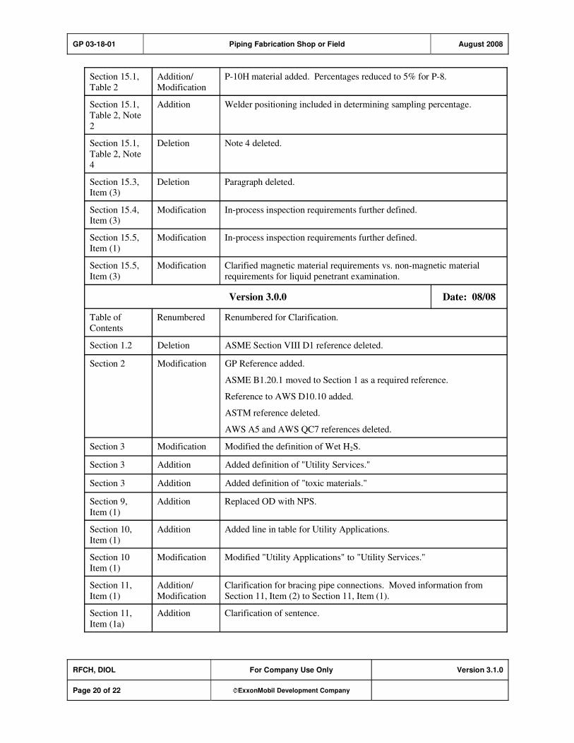
GP 03-18-01 Piping Fabrication Shop or Field August 2008
RFCH, DIOL For Company Use Only Version 3.1.0
Page 20 of 22 ExxonMobil Development Company
Section 15.1,
Table 2
Addition/
Modification
P-10H material added. Percentages reduced to 5% for P-8.
Section 15.1,
Table 2, Note
2
Addition Welder positioning included in determining sampling percentage.
Section 15.1,
Table 2, Note
4
Deletion Note 4 deleted.
Section 15.3, Item (3)
Deletion Paragraph deleted.
Section 15.4, Item (3)
Modification In-process inspection requirements further defined.
Section 15.5,
Item (1)
Modification In-process inspection requirements further defined.
Section 15.5,
Item (3)
Modification Clarified magnetic material requirements vs. non-magnetic material
requirements for liquid penetrant examination.
Version 3.0.0 Date: 08/08
Table of
Contents
Renumbered Renumbered for Clarification.
Section 1.2 Deletion ASME Section VIII D1 reference deleted.
Section 2 Modification GP Reference added.
ASME B1.20.1 moved to Section 1 as a required reference.
Reference to AWS D10.10 added.
ASTM reference deleted.
AWS A5 and AWS QC7 references deleted.
Section 3 Modification Modified the definition of Wet H2S.
Section 3 Addition Added definition of "Utility Services."
Section 3 Addition Added definition of "toxic materials."
Section 9,
Item (1)
Addition Replaced OD with NPS.
Section 10,
Item (1)
Addition Added line in table for Utility Applications.
Section 10
Item (1)
Modification Modified "Utility Applications" to "Utility Services."
Section 11,
Item (1)
Addition/
Modification
Clarification for bracing pipe connections. Moved information from
Section 11, Item (2) to Section 11, Item (1).
Section 11,
Item (1a)
Addition Clarification of sentence.
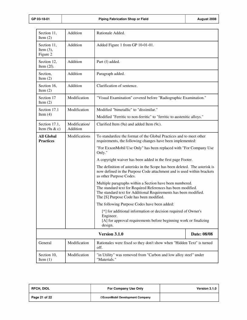
GP 03-18-01 Piping Fabrication Shop or Field August 2008
RFCH, DIOL For Company Use Only Version 3.1.0
Page 21 of 22 ExxonMobil Development Company
Section 11,
Item (2)
Addition Rationale Added.
Section 11,
Item (3),
Figure 2
Addition Added Figure 1 from GP 10-01-01.
Section 12,
Item (2f).
Addition Part (f) added.
Section,
Item (2)
Addition Paragraph added.
Section 16,
Item (2)
Addition Clarification of sentence.
Section 17 Item (2)
Modification "Visual Examination" covered before "Radiographic Examination."
Section 17.1
Item (4)
Modification Modified "bimetallic" to "dissimilar."
Modified "Ferritic to non-ferritic" to "ferritic to austenitic alloys."
Section 17.1,
Item (9a & c)
Modification/
Addition
Clarified Item (9a) and added Item (9c).
All Global
Practices
Modifications To standardize the format of the Global Practices and to meet other
requirements, the following changes have been implemented:
"For ExxonMobil Use Only" has been replaced with "For Company Use
Only."
A copyright waiver has been added in the first page Footer.
The definition of asterisks in the Scope has been deleted. The asterisk is
now defined in the Purpose Code attachment and is used within brackets
as other Purpose Codes.
Multiple paragraphs within a Section have been numbered.
The standard text for Required References has been modified.
The standard text for Additional Requirements has been modified. The [S] Purpose Code has been modified.
The following Purpose Codes have been added:
[*] for additional information or decision required of Owner's
Engineer.
[A] for approval requirements before beginning work or finalizing
design.
Version 3.1.0 Date: 08/08
General Modification Rationales were fixed so they don't show when "Hidden Text" is turned
off.
Section 10,
Item (1)
Modification "in Utility" was removed from "Carbon and low alloy steel" under
"Materials."

GP 03-18-01 Piping Fabrication Shop or Field August 2008
RFCH, DIOL For Company Use Only Version 3.1.0
Page 22 of 22 ExxonMobil Development Company
Attachment: Purpose Code Definitions
Code Description
* Assigned to paragraphs that require the Owner's Engineer to provide additional information or
make a decision.
A Assigned to paragraphs that require approval from the Owner's Engineer before the work may
proceed or the design is finalized.
C Assigned to paragraphs whose primary purpose is reduced costs. Reduced cost in this context
refers to initial investment cost and does not include life cycle cost considerations. Life cycle
cost considerations are captured under reliability, maintainability, or operability purpose codes.
E Assigned to paragraphs whose primary purpose is driven by environmental considerations. Environmental considerations typically include specifications intended to protect against
emissions/leakage to the air, water, and/or soil. Deviations from the specifications contained
in such paragraphs require formal review and approval according to local environmental policy.
I Assigned to paragraphs that provide only clarifying information, such as Scope statements,
definitions of terms, etc.
M Assigned to paragraphs whose primary purpose is to provide for maintainability of equipment or systems. Maintainability provisions are those that facilitate the performance of maintenance
on equipment/systems either during downtimes or during onstream operations.
O Assigned to paragraphs whose primary purpose is to assure operability of equipment or
systems. Operability is the ability of the equipment/system to perform satisfactorily even though conditions are off-design, such as during start-ups, process swings, subcomponent
malfunction, etc.
R Assigned to paragraphs whose primary purpose is to improve or assure the reliability of
equipment or systems. Reliability is a measure of the ability of equipment/systems to operate without malfunction or failure between planned maintenance interventions.
S Assigned to paragraphs containing specifications/guidance where the primary purpose is the
avoidance of incidents impacting personnel safety, operational safety, and the public in general and/or involving responses to emergency situations. Any deviation from the specifications
contained in such designated paragraphs requires formal review and approval according to
local safety policy.
Personnel Safety: Refers to incident-related personnel injuries or illness, e.g., burns, cuts, abrasions, inhalation of or exposure to dangerous substances, etc., that
could result in medical treatment, restricted work, lost-time incidents, or
fatalities.
Operational
Safety:
Refers to the prevention and control of process releases, fires, and/or
explosions that could result in damage to equipment, process disruption,
or personnel injury or illness.

GP 04-01-04 Surge Vibration Design Loads October 2004
Refining/Chemicals, Downstream Imperial Oil
For ExxonMobil Use Only Version 2.0.0
Page 1 of 7 ExxonMobil Development Company
Surge Vibration Design Loads
GP 04-01-04
Scope
[I] This Global Practice (GP) covers the calculation of surge forces for fluidized solids process vessels and support structures that are subject to surge vibration.
[I] An asterisk (*) indicates that additional information is required. If a job is contracted, this additional
information is furnished in the Job Specification.
GP 04-01-04 Surge Vibration Design Loads October 2004
RFCH, DIOL For ExxonMobil Use Only Version 2.0.0
Page 2 of 7 ExxonMobil Development Company
Table of Contents
1. Definitions.............................................................................................................. 3
2. Symbols ................................................................................................................. 3
3. Design .................................................................................................................... 3
Record of Change ......................................................................................................... 3
Attachment: Purpose Codes Definitions.................................................................... 3
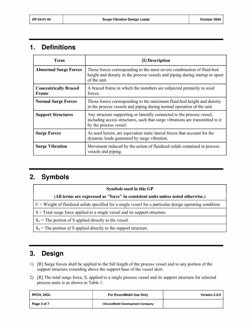
GP 04-01-04 Surge Vibration Design Loads October 2004
RFCH, DIOL For ExxonMobil Use Only Version 2.0.0
Page 3 of 7 ExxonMobil Development Company
1. Definitions
Term [I] Description
Abnormal Surge Forces Those forces corresponding to the most severe combination of fluid-bed
height and density in the process vessels and piping during startup or upset of the unit.
Concentrically Braced
Frame
A braced frame in which the members are subjected primarily to axial
forces.
Normal Surge Forces Those forces corresponding to the maximum fluid-bed height and density
in the process vessels and piping during normal operation of the unit.
Support Structures Any structure supporting or laterally connected to the process vessel,
including access structures, such that surge vibrations are transmitted to it
by the process vessel.
Surge Forces As used herein, are equivalent static lateral forces that account for the dynamic loads generated by surge vibration.
Surge Vibration Movement induced by the action of fluidized solids contained in process
vessels and piping.
2. Symbols
Symbols used in this GP
(All terms are expressed as "force" in consistent units unless noted otherwise.)
C = Weight of fluidized solids specified for a single vessel for a particular design operating condition.
S = Total surge force applied to a single vessel and its support structure.
SV = The portion of S applied directly to the vessel.
SS = The portion of S applied directly to the support structure.
3. Design
1) [R] Surge forces shall be applied to the full length of the process vessel and to any portion of the support structure extending above the support base of the vessel skirt.
2) [R] The total surge force, S, applied to a single process vessel and its support structure for selected
process units is as shown in Table 1.

GP 04-01-04 Surge Vibration Design Loads October 2004
RFCH, DIOL For ExxonMobil Use Only Version 2.0.0
Page 4 of 7 ExxonMobil Development Company
Table 1: Total Surge Force
Type of Process Unit S
Flexicoking 0.15 C
Fluid Coking 0.15 C
Gas Conversion FBSG 0.15 C
Flexicracking 0.075 C
Fluid Catalytic Cracking 0.075 C
3) [I] Weight, C, of fluid-solids to be used for calculating surge shall be as follows, unless specified otherwise:
a) For normal surge force: C is the maximum weight of fluid-solids in a single vessel and
associated piping during normal operation.
b) For abnormal surge force: C is the maximum weight of fluid-solids in a single vessel and associated piping during abnormal (startup or upset) conditions resulting in the most severe
combination of fluid-bed height and density in the vessel.
4) [R] The total surge force, S, shall be divided between the vessel and the portion of the support
structure extending above the base of the vessel skirt according to their relative weights.
5) [R] The surge force, Ss, shall be distributed over the portion of the support structure located above the
base level of the vessel support according to the tribulary mass weighted by its height above the vessel support level. The surge force for the structure shall not exceed 20 percent of the total surge
force, S.
6) [R] The surge force Sv for the vessel shall be calculated as follows:
Sv = S Ss
Its distribution over the height of the vessel shall be according to the tributary mass weighted by its
height above or below the support level of the vessel.
7) [R] The total number of levels used to distribute the surge forces shall be sufficient to represent the vertical weight and stiffness distribution of the vessel and of the support structure. The number of
levels on the vessel shall not be less than the total height of the vessel divided by its largest outside
diameter.
8) [R] Surge forces shall be considered to act in any horizontal direction that causes the largest stresses, overturning moments, or deflection.
9) [R] Surge forces applied to the vessel and to the support structure shall be considered to act
simultaneously in each of the following combinations:
a) The surge forces on the vessel and on the support structure acting in the same direction
b) The surge forces on the vessel acting in the opposite direction of the surge forces on the support
structure
c) The surge forces on the support structure and on the vessel above the skirt acting in the opposite
direction of the surge forces on the vessel below the skirt to produce the maximum base rotation

GP 04-01-04 Surge Vibration Design Loads October 2004
RFCH, DIOL For ExxonMobil Use Only Version 2.0.0
Page 5 of 7 ExxonMobil Development Company
10) [R] Relative stiffness of the vessel, the support structure, and vessel to support structure connections
shall all be considered when determining how the surge forces are transmitted between the vessel and
the support structure.
11) [R] If two or more vessels are supported by or connected to a common support structure, all surge
forces shall be considered to act simultaneously. However, only feasible combinations of fluid-bed
height and density that could simultaneously occur in all the vessels for a particular normal or
abnormal condition shall be considered.
12) [R] Lateral force resisting systems shall consist of concentrically braced frames in both directions.
13) [R]There is no limit on lateral deflections for combinations that include Surge loads.
14) [R] Members and connections shall be checked for fatigue assuming two million loading cycles using
stresses from normal surge loads only.

GP 04-01-04 Surge Vibration Design Loads October 2004
RFCH, DIOL For ExxonMobil Use Only Version 2.0.0
Page 6 of 7 ExxonMobil Development Company
Record of Change
Version 1.0.0 Date: 07/01
Location Action Description
Initial Publish.
Version 1.0.0 Date: 09/03
Global Practice version number and format updated to comply with new
process; however, original publish date remains, and no content was
modified.
Version 2.0.0 Date: 10/04
Section 1 Addition Concentrically Braced frame definition
Section 3, Item
4
Addition Rationale
Section 3, Item
12
Addition Concentrically Braced Frames requirement
Section 3, Item
13
Addition Clarification on deflection criteria
Section 3, Item
14
Addition Fatigue

GP 04-01-04 Surge Vibration Design Loads October 2004
RFCH, DIOL For ExxonMobil Use Only Version 2.0.0
Page 7 of 7 ExxonMobil Development Company
Attachment: Purpose Codes Definitions
Code Description
C Assigned to paragraphs containing specifications whose primary purpose is reduced costs.
Reduced cost in this context refers to initial investment cost and does not include Life-Cycle
cost considerations. Life-Cycle cost considerations are captured under reliability,
maintainability, or operability purpose codes.
E Assigned to paragraphs containing specifications whose primary purpose is driven by
environmental considerations. Environmental considerations typically include specifications
intended to protect against emissions/leakage to the air, water, and/or soil. Deviations from the specifications contained in such paragraphs require formal review and approval according to
local environmental policy.
I Assigned to paragraphs that provide only clarifying information such as Scope statements,
definitions of terms, etc.
M Assigned to paragraphs containing specifications whose primary purpose is to provide for
maintainability of equipment or systems. Maintainability provisions are those that facilitate the
performance of maintenance on equipment/systems either during downtimes or during on-
stream operations.
O Assigned to paragraphs containing specifications whose primary purpose is to assure
operability of equipment or systems. Operability is the ability of the equipment/system to
perform satisfactorily even though conditions are off-design, such as during startups, process swings, subcomponent malfunction, etc.
R Assigned to paragraphs containing specifications whose primary purpose is to improve or
assure the reliability of equipment or systems. Reliability is a measure of the ability of
equipment/systems to operate without malfunction or failure between planned maintenance interventions.
S Assigned to paragraphs containing specifications whose primary purpose is avoidance of
personnel or operational safety incidents. Any deviation from the specifications contained in
such designated paragraphs requires formal review and approval according to local safety policy.
Personnel Safety: Refers to the avoidance of recordable personnel injuries; i.e., burns, cuts,
abrasions, inhalation, or exposure to dangerous substances, etc., that could result in medical treatment, restricted work, lost-time incidents, or
fatalities.
Operational
Safety:
Refers to the prevention and control of process releases, fires, explosions,
etc.

GP 04-14-01 Equipment Lifts by Cranes April 2007
Refining/Chemicals, Downstream Imperial Oil
For Company Use Only Version 2.0.0
Page 1 of 11 ExxonMobil Development Company
Copyright Waiver ExxonMobil Development Company and ExxonMobil Pipeline Company hereby license the use of ExxonMobil Engineering Practices System (EMEPS) Global Practices (GPs) for use by any ExxonMobil division, subsidiary, or more-than-50%-owned affiliate. The GPs may be downloaded and modified as necessary for project and affiliate use. Written permission from ExxonMobil Development Company or ExxonMobil Pipeline Company is not required. However, any modified GPs must be renumbered to a project-specific or affiliate-specific number to distinguish them from the GPs on the EMEPS web site. ExxonMobil operated joint ventures may utilize GPs to create project-specific or location-specific specifications. It is the responsibility of individual affiliate or joint venture to ensure that the use of GPs and their derivatives is limited to joint venture related business and not disclosed or used outside the JV without appropriate EM management approval.
Equipment Lifts by Cranes
GP 04-14-01
Scope
1) [I] This Global Practice (GP) covers lifts using cranes associated with the erection and dismantling of
plant equipment and structures. It does not cover lifts using other devices such as hydraulic jacks or permanent or fixed lifting equipment, such as overhead trolleys, exchanger hoists, etc.
2) [I] This GP is applicable only to onshore applications including inland and near shore terminals.
GP 04-14-01 Equipment Lifts by Cranes April 2007
RFCH, DIOL For Company Use Only Version 2.0.0
Page 2 of 11 ExxonMobil Development Company
Table of Contents
1. Required References ............................................................................................ 3
1.1. Global Practices–ExxonMobil Engineering Practices ................................... 3
1.2. AISC–American Institute of Steel Construction ............................................ 3
1.3. ASCE–American Society of Civil Engineers ................................................. 3
1.4. ASME–American Society of Mechanical Engineers ..................................... 3
1.5. ASTM-American Society for Testing and Materials ...................................... 4
1.6. Other Publications ........................................................................................ 4
2. Definitions.............................................................................................................. 4
3. Materials................................................................................................................. 5
4. Design .................................................................................................................... 5
5. Welding Requirements ......................................................................................... 6
6. Crane Requirements ............................................................................................. 7
1. Lift Plans ................................................................................................................ 8
1.1. Critical Lift Plans........................................................................................... 8
Record of Change ....................................................................................................... 10
Attachment: Purpose Code Definitions.................................................................... 11

GP 04-14-01 Equipment Lifts by Cranes April 2007
RFCH, DIOL For Company Use Only Version 2.0.0
Page 3 of 11 ExxonMobil Development Company
1. Required References
1) This section lists the Practices, codes, standards, specifications, and publications that shall be used with this document. Unless otherwise specified herein, use the latest edition.
2) All sections of the Practices, codes, standards, specifications, and publications are to be applicable.
All requirements specified in this GP are additions to those of the documents referenced in this
section unless specifically noted as exceptions.
3) Local codes and standards may be substituted for those referenced herein, provided the following provisions are met:
a) The resultant design meets the safety and serviceability criteria attained through this GP.
b) [A] Substitution is accepted by the authorities at the facility location and by Owner's Engineer.
1.1. Global Practices–ExxonMobil Engineering Practices
GP 05-01-01 Pressure Vessels
GP 18-07-01 Welding Procedures
1.2. AISC–American Institute of Steel Construction
AISC 360 Specification for Structural Steel Buildings
1.3. ASCE–American Society of Civil Engineers
ASCE 7 Minimum Design Loads for Buildings and Other Structures
1.4. ASME–American Society of Mechanical Engineers
ASME B30.3 Construction Tower Cranes
ASME B30.4 Portal, Tower, and Pedestal Cranes
ASME B30.5 Mobile and Locomotive Cranes
ASME B30.6 Derricks
ASME B30.9 Slings
ASME B30.10 Hooks - Safety Standard for Cableways, Cranes, Derricks, Hoists,
Hooks, Jacks, and Slings
ASME B30.20 Below-the-Hook Lifting Devices
ASME B30.22 Articulating Boom Cranes
ASME B30.23 Personnel Lifting Systems Safety Standard for Cableways, Cranes, Derricks, Hoists, Hooks, Jacks, and Slings

GP 04-14-01 Equipment Lifts by Cranes April 2007
RFCH, DIOL For Company Use Only Version 2.0.0
Page 4 of 11 ExxonMobil Development Company
ASME B30.26 Rigging Hardware Safety Standard for Cableways, Cranes, Derricks,
Hoists, Hooks, Jacks, and Slings
ASME BTH-1 Design of Below-the-Hook Lifting Devices
1.5. ASTM-American Society for Testing and Materials
ASTM A 36/A 36M Standard Specification for Carbon Structural Steel
1.6. Other Publications
TMEE 233 ExxonMobil Onshore Crane/Lifting Safety Management Guide
2. Definitions
[I] Equipment (as used in this Practice) to be lifted is synonymous with structures to be lifted.
Term [I] Description
Cranes Land-based equipment and machinery used to lift, lower, and swing
loads at various radii. These include, but are not limited to:
crawler-mounted lattice boom; carrier-mounted lattice and telescope
boom; stiffleg and guy derricks; pedestal; rough terrain; all terrain; boom truck and carry deck; tower cranes; overhead and gantry
cranes, as well as lift enhancing attachments for these cranes.
Lifts meeting one or more of the following, unless Owner, through risk assessment, specifies otherwise:
1) The load is being lifted over or near an occupied building,
operating equipment, or electrical power-lines.
2) Two or more pieces of lifting equipment are required to work in unison. (This includes using a tailing crane.)
3) Special lifting equipment, such as ginpoles or non-standard
crane configurations, is used.
4) The load is greater than 50 tons (45 metric tons).
5) The load represents more than 90 percent of the manufacturer's
rated capacity at the working radius.
Critical Lifts
6) The load is greater than 20 tons (18 metric tons) and is also greater than 80 percent of the manufacturer's rated capacity.
Engineered Lifting
Components
Rigging hardware designed to meet the requirements of a specific
lift or lifts.
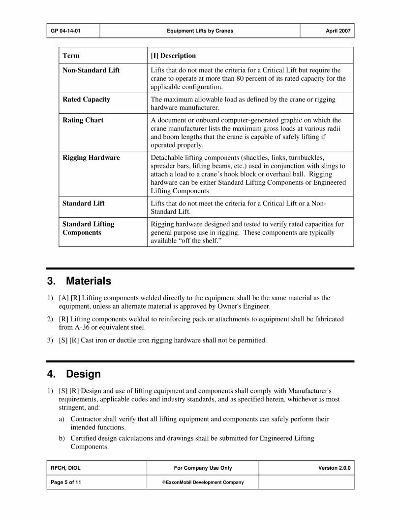
GP 04-14-01 Equipment Lifts by Cranes April 2007
RFCH, DIOL For Company Use Only Version 2.0.0
Page 5 of 11 ExxonMobil Development Company
Term [I] Description
Non-Standard Lift Lifts that do not meet the criteria for a Critical Lift but require the
crane to operate at more than 80 percent of its rated capacity for the
applicable configuration.
Rated Capacity The maximum allowable load as defined by the crane or rigging hardware manufacturer.
Rating Chart A document or onboard computer-generated graphic on which the
crane manufacturer lists the maximum gross loads at various radii
and boom lengths that the crane is capable of safely lifting if operated properly.
Rigging Hardware Detachable lifting components (shackles, links, turnbuckles,
spreader bars, lifting beams, etc.) used in conjunction with slings to attach a load to a crane’s hook block or overhaul ball. Rigging
hardware can be either Standard Lifting Components or Engineered
Lifting Components
Standard Lift Lifts that do not meet the criteria for a Critical Lift or a Non-Standard Lift.
Standard Lifting
Components
Rigging hardware designed and tested to verify rated capacities for
general purpose use in rigging. These components are typically available “off the shelf.”
3. Materials
1) [A] [R] Lifting components welded directly to the equipment shall be the same material as the
equipment, unless an alternate material is approved by Owner's Engineer.
2) [R] Lifting components welded to reinforcing pads or attachments to equipment shall be fabricated from A-36 or equivalent steel.
3) [S] [R] Cast iron or ductile iron rigging hardware shall not be permitted.
4. Design
1) [S] [R] Design and use of lifting equipment and components shall comply with Manufacturer's
requirements, applicable codes and industry standards, and as specified herein, whichever is most stringent, and:
a) Contractor shall verify that all lifting equipment and components can safely perform their
intended functions.
b) Certified design calculations and drawings shall be submitted for Engineered Lifting
Components.
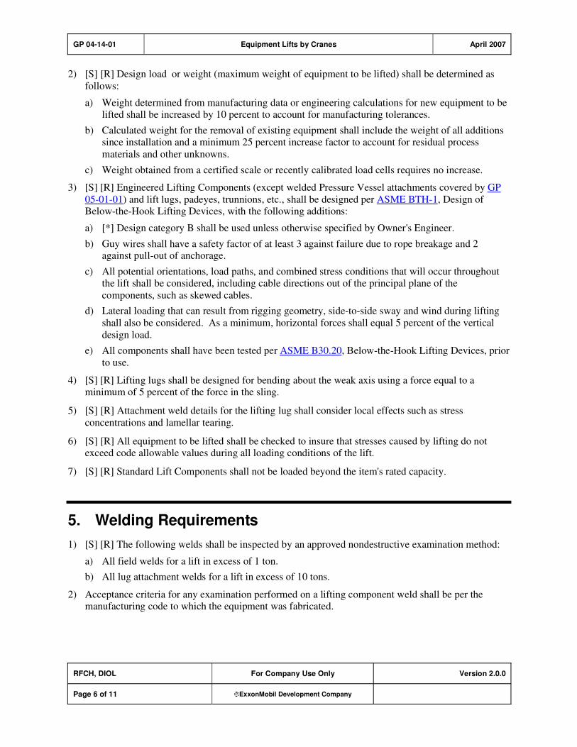
GP 04-14-01 Equipment Lifts by Cranes April 2007
RFCH, DIOL For Company Use Only Version 2.0.0
Page 6 of 11 ExxonMobil Development Company
2) [S] [R] Design load or weight (maximum weight of equipment to be lifted) shall be determined as
follows:
a) Weight determined from manufacturing data or engineering calculations for new equipment to be lifted shall be increased by 10 percent to account for manufacturing tolerances.
b) Calculated weight for the removal of existing equipment shall include the weight of all additions since installation and a minimum 25 percent increase factor to account for residual process
materials and other unknowns.
c) Weight obtained from a certified scale or recently calibrated load cells requires no increase.
3) [S] [R] Engineered Lifting Components (except welded Pressure Vessel attachments covered by GP
05-01-01) and lift lugs, padeyes, trunnions, etc., shall be designed per ASME BTH-1, Design of Below-the-Hook Lifting Devices, with the following additions:
a) [*] Design category B shall be used unless otherwise specified by Owner's Engineer.
b) Guy wires shall have a safety factor of at least 3 against failure due to rope breakage and 2 against pull-out of anchorage.
c) All potential orientations, load paths, and combined stress conditions that will occur throughout the lift shall be considered, including cable directions out of the principal plane of the
components, such as skewed cables.
d) Lateral loading that can result from rigging geometry, side-to-side sway and wind during lifting
shall also be considered. As a minimum, horizontal forces shall equal 5 percent of the vertical
design load.
e) All components shall have been tested per ASME B30.20, Below-the-Hook Lifting Devices, prior
to use.
4) [S] [R] Lifting lugs shall be designed for bending about the weak axis using a force equal to a minimum of 5 percent of the force in the sling.
5) [S] [R] Attachment weld details for the lifting lug shall consider local effects such as stress
concentrations and lamellar tearing.
6) [S] [R] All equipment to be lifted shall be checked to insure that stresses caused by lifting do not exceed code allowable values during all loading conditions of the lift.
7) [S] [R] Standard Lift Components shall not be loaded beyond the item's rated capacity.
5. Welding Requirements
1) [S] [R] The following welds shall be inspected by an approved nondestructive examination method:
a) All field welds for a lift in excess of 1 ton.
b) All lug attachment welds for a lift in excess of 10 tons.
2) Acceptance criteria for any examination performed on a lifting component weld shall be per the manufacturing code to which the equipment was fabricated.

GP 04-14-01 Equipment Lifts by Cranes April 2007
RFCH, DIOL For Company Use Only Version 2.0.0
Page 7 of 11 ExxonMobil Development Company
6. Crane Requirements
1) [S] No crane shall lift any load in any configuration which exceeds 80 percent of its rated capacity for that configuration unless the requirements of either a Non-Standard or Critical Lift have been met.
2) [S] [R] All cranes shall have been inspected by a qualified person (certified by local, regional, or
national authorities) within the past 12 months. A copy of the most recent inspection report shall be
available for review by Owner's Representative.
3) [S] [R] No crane showing evidence of repairs or modifications shall be allowed to begin work without the Manufacturer's written approval of the repair or modification.
4) [S] No crane shall lift any load in any configuration unless there is, in or on the crane, a current rating
chart.
5) [S] All cranes shall be outfitted with the following electronic safety devices (operating aids):
a) System which shuts off power to the hoist mechanism (Overhoisting Limiter) and/or activates an
alarm (Overhoisting Indicator) when the load block or overhaul ball is hoisted too near the boom
or jib tip and
b) One of the following:
i) System which measures the weight on the hook and displays the load weight (Load Indicating Device), or
ii) Electronic system which displays to the crane operator the weight on the hook, radius, and/or percentage of rated capacity [Rated Capacity Indicator, Load Moment Indicator (LMI)], or
iii) Electronic system similar to an LMI that is also tied into the crane's control system and will automatically shut off power and set the brakes if an overload condition is reached (Rated
Capacity Limiter).
6) [S] A minimum boom-to-load clearance of 3 ft (1 m) shall be maintained for all lifting operations unless positive load control systems (tag lines) are being employed to restrict load movement. The
minimum boom-to-obstruction clearance is 3 ft. (1 m).
7) [S] Any overhead electrical line shall be considered energized unless Owner of the line or electrical
utility authority is on the site and verifies that the wire is not energized and the line is visibly grounded.
8) [S] [*] [R] All crane operators shall be fully certified, if a certification procedure exists at location or
is required by local regulations.
9) [S] [R] All rigging hardware shall be marked, as a minimum, with the manufacturer's name or logo
and the rated capacity.
10) [S] [R] Operating aids, e.g., Load Indicating Devices, shall not be used as the primary load weight determining mechanism.
11) [S] The minimum required clearance between high voltage electrical lines that are not de-energized,
and any part of the crane, load, or load line shall be as shown in Table 1. Local codes that are more restrictive shall govern.

GP 04-14-01 Equipment Lifts by Cranes April 2007
RFCH, DIOL For Company Use Only Version 2.0.0
Page 8 of 11 ExxonMobil Development Company
Table 1: Minimum Clearances between Electrical Lines and Crane and/or
Loads
During Crane Operation During Transit (No Load, and Boom or
Mast Lowered)
Voltage
kV
Clearance
ft (m)
Voltage
kV
Clearance
ft (m)
< 50 10 (3.1) < 0.75 4 (1.2)
50–200 15 (4.6) 0.75–50 6 (1.8)
201–350 20 (6.1) 51–345 10 (3.1)
351–500 25 (7.6) 346–750 16 (4.9)
501–750 35 (10.7) 751–1000 20 (6.1)
751–1000 45 (13.7) – –
12) [S] [*] [A] [O] [R] Crane shall be supported on firm, stable base or foundation. Loads imposed by
the crane shall not exceed the allowable bearing capacity of the soil, per Soil Report, or as specified.Foundations for cranes shall be submitted to Owner's Engineer for review.
13) [S] [O] [R] All personnel involved with lifting activities shall be properly trained, qualified, and
competent to perform their assigned task.
7. Lift Plans
1) [S] Standard lifts need to be logged in a daily log prior to each lift. The log should record, at a
minimum, the weight of the load, the radius at which it should be handled, and the rated capacity of the crane at that radius for each lift and the maximum weight and radius for a group of repetitive,
similar lifts.
2) [S] Non-standard lifts require a written lift evaluation. The evaluation should consider the load and
rigging weights, crane configuration, crane capacity, crane support conditions, and any nearby hazards.
3) [S] [A] Critical lifts require an approved Critical Lift Plan.
7.1. Critical Lift Plans
1) [A] All critical lifts shall be reviewed by a qualified person.
2) All critical lifts require a Critical Lift Plan that shall consist of drawings, specifications, and
procedures as necessary to accurately assess all important load and site factors. The Critical Lift Plan shall include, but not be limited to, the following:
a) Elevation view drawing(s) of the crane, load, and any nearby structures that could cause
interference problems. The drawing shall be to scale and note the following:

GP 04-14-01 Equipment Lifts by Cranes April 2007
RFCH, DIOL For Company Use Only Version 2.0.0
Page 9 of 11 ExxonMobil Development Company
i) Crane manufacturer(s), model(s), and counterweights
ii) Boom length(s) and lifting radius (i)
iii) Maximum load elevation during lifting procedure
iv) Any jibs or special lifting devices required
v) Minimum number of parts of crane hoist line required to lift the load
vi) Minimum boom clearances (load, obstructions, or power lines)
vii) All required blocks, slings, shackles, and other rigging hardware identified by capacity, size,
length, and location.
b) Plan view drawing(s) of the crane, load, and nearby structures that could cause interference. The
drawing shall be to scale and include:
i) Route the transport will take to position the load for lifting
ii) Initial lifting position of the load, including radius
iii) Final placement position of the load, including radius
iv) Location of the crane(s), including tail-swing limits
v) Location and depth of nearby underground pipes and structures
vi) Bearing pressures generated by the crane and the location, thickness, etc., of any required
mats or cribbing.
c) Lift analysis including:
i) Tabulation of the gross load weight including all blocks, jib and rigging tackle weight
ii) Gross rated capacity of the crane in the configuration specified
iii) Net lifting capacity of the crane, detailing any necessary deductions from the crane's gross
lifting capacity for all hardware such as jibs, etc.
iv) Calculation of the percent of the crane's gross rated capacity for the lift
v) Weather limitations, e.g., wind speeds, temperature constraints
vi) Determination of crane foundation requirements
vii) Emergency procedures and communications plan
viii) Details of how the rigging hardware will be removed
ix) A narrative of the step-by-step crane movements and load manipulation
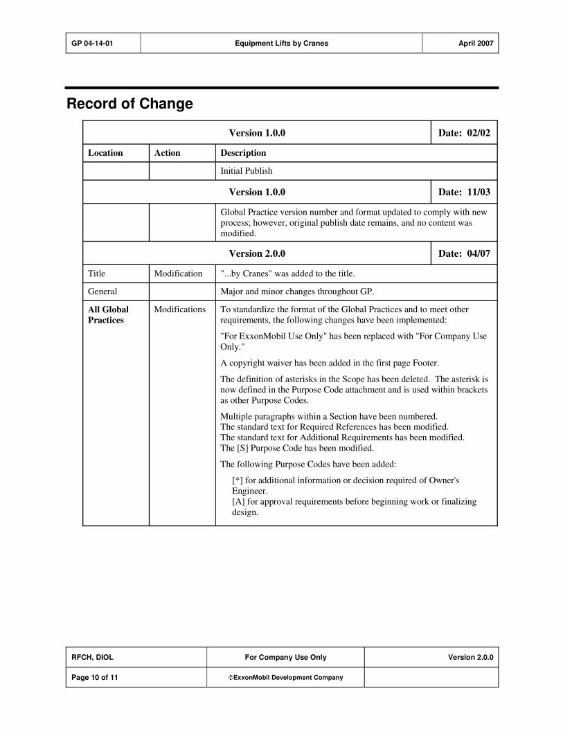
GP 04-14-01 Equipment Lifts by Cranes April 2007
RFCH, DIOL For Company Use Only Version 2.0.0
Page 10 of 11 ExxonMobil Development Company
Record of Change
Version 1.0.0 Date: 02/02
Location Action Description
Initial Publish
Version 1.0.0 Date: 11/03
Global Practice version number and format updated to comply with new
process; however, original publish date remains, and no content was
modified.
Version 2.0.0 Date: 04/07
Title Modification "...by Cranes" was added to the title.
General Major and minor changes throughout GP.
All Global
Practices
Modifications To standardize the format of the Global Practices and to meet other
requirements, the following changes have been implemented:
"For ExxonMobil Use Only" has been replaced with "For Company Use
Only."
A copyright waiver has been added in the first page Footer.
The definition of asterisks in the Scope has been deleted. The asterisk is
now defined in the Purpose Code attachment and is used within brackets
as other Purpose Codes.
Multiple paragraphs within a Section have been numbered. The standard text for Required References has been modified.
The standard text for Additional Requirements has been modified.
The [S] Purpose Code has been modified.
The following Purpose Codes have been added:
[*] for additional information or decision required of Owner's
Engineer.
[A] for approval requirements before beginning work or finalizing
design.
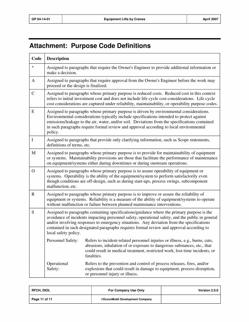
GP 04-14-01 Equipment Lifts by Cranes April 2007
RFCH, DIOL For Company Use Only Version 2.0.0
Page 11 of 11 ExxonMobil Development Company
Attachment: Purpose Code Definitions
Code Description
* Assigned to paragraphs that require the Owner's Engineer to provide additional information or
make a decision.
A Assigned to paragraphs that require approval from the Owner's Engineer before the work may
proceed or the design is finalized.
C Assigned to paragraphs whose primary purpose is reduced costs. Reduced cost in this context
refers to initial investment cost and does not include life cycle cost considerations. Life cycle
cost considerations are captured under reliability, maintainability, or operability purpose codes.
E Assigned to paragraphs whose primary purpose is driven by environmental considerations. Environmental considerations typically include specifications intended to protect against
emissions/leakage to the air, water, and/or soil. Deviations from the specifications contained
in such paragraphs require formal review and approval according to local environmental policy.
I Assigned to paragraphs that provide only clarifying information, such as Scope statements,
definitions of terms, etc.
M Assigned to paragraphs whose primary purpose is to provide for maintainability of equipment or systems. Maintainability provisions are those that facilitate the performance of maintenance
on equipment/systems either during downtimes or during onstream operations.
O Assigned to paragraphs whose primary purpose is to assure operability of equipment or
systems. Operability is the ability of the equipment/system to perform satisfactorily even though conditions are off-design, such as during start-ups, process swings, subcomponent
malfunction, etc.
R Assigned to paragraphs whose primary purpose is to improve or assure the reliability of
equipment or systems. Reliability is a measure of the ability of equipment/systems to operate without malfunction or failure between planned maintenance interventions.
S Assigned to paragraphs containing specifications/guidance where the primary purpose is the
avoidance of incidents impacting personnel safety, operational safety, and the public in general and/or involving responses to emergency situations. Any deviation from the specifications
contained in such designated paragraphs requires formal review and approval according to
local safety policy.
Personnel Safety: Refers to incident-related personnel injuries or illness, e.g., burns, cuts, abrasions, inhalation of or exposure to dangerous substances, etc., that
could result in medical treatment, restricted work, lost-time incidents, or
fatalities.
Operational
Safety:
Refers to the prevention and control of process releases, fires, and/or
explosions that could result in damage to equipment, process disruption,
or personnel injury or illness.

GP 05-01-01 Pressure Vessels June 2007
Refining/Chemicals For Company Use Only Version 3.1.0
Page 1 of 36 ExxonMobil Development Company
Copyright Waiver ExxonMobil Development Company and ExxonMobil Pipeline Company hereby license the use of ExxonMobil Engineering Practices System (EMEPS) Global Practices (GPs) for use by any ExxonMobil division, subsidiary, or more-than-50%-owned affiliate. The GPs may be downloaded and modified as necessary for project and affiliate use. Written permission from ExxonMobil Development Company or ExxonMobil Pipeline Company is not required. However, any modified GPs must be renumbered to a project-specific or affiliate-specific number to distinguish them from the GPs on the EMEPS web site. ExxonMobil operated joint ventures may utilize GPs to create project-specific or location-specific specifications. It is the responsibility of individual affiliate or joint venture to ensure that the use of GPs and their derivatives is limited to joint venture related business and not disclosed or used outside the JV without appropriate EM management approval.
Pressure Vessels
GP 05-01-01
Scope
1) [I] This Global Practice (GP) covers the design, fabrication, inspection, and testing of unfired
pressure vessels, including all unfired steam generators and non-refrigerated carbon steel pressure storage spheres.
2) Additional requirements are found in GP 09-02-01 for spheres, and in GP 05-01-02 for vessels that
meet any of the following special criteria:
a) Wall thickness is in excess of 2 in. (50 mm) and up to 6 in. (150 mm).
b) Material of construction is ferritic alloy steel (Cr-Mo, Mn-Mo, etc.).
c) Material of construction is Quenched and Tempered (Q&T) steel.
d) Material of construction has a specified yield strength that exceeds 52200 psi (360 MPa).
e) Vessel is in cyclic service.
3) [I] Small commercial vessels which are not part of process equipment (such as sandblast machines,
paint sprayers, and gunite machines) are outside the scope of this practice.

GP 05-01-01 Pressure Vessels June 2007
RFCH For Company Use Only Version 3.1.0
Page 2 of 36 ExxonMobil Development Company
Table of Contents
Table of Tables .............................................................................................................. 4
1. Required References ............................................................................................ 5
1.1. Global Practices–ExxonMobil Engineering Practices ................................... 5
1.2. ExxonMobil Data Sheets .............................................................................. 5
2. Additional Requirements...................................................................................... 6
2.1. Global Practices–ExxonMobil Engineering Practices ................................... 6
2.2. API–American Petroleum Institute................................................................ 6
2.3. ASME–American Society of Mechanical Engineers ..................................... 6
2.4. ASTM–American Society for Testing and Materials ..................................... 7
2.5. BSI–British Standards Institute..................................................................... 7
2.6. WRC–Welding Research Council................................................................. 7
3. Definitions.............................................................................................................. 7
4. Proposals............................................................................................................... 8
5. Documentation ...................................................................................................... 8
5.1. Drawings ...................................................................................................... 8
5.2. Data and Calculations .................................................................................. 9
6. Materials............................................................................................................... 10
7. Design .................................................................................................................. 10
7.1. Design Requirements ................................................................................. 10
7.2. Design Loads ............................................................................................. 11
7.3. Vibration Analysis ....................................................................................... 12
7.4. Allowable Stresses ..................................................................................... 13
7.5. Vessel Thickness........................................................................................ 13
7.6. Heads and Transition Sections................................................................... 15
7.7. Nozzles and Manways................................................................................ 15
7.8. Vents .......................................................................................................... 17
7.9. Vessel Supports and Attachments.............................................................. 18
7.10. Proprietary Construction............................................................................. 20
8. Additional Requirements for Flanged Shell Girth Joints................................. 20

GP 05-01-01 Pressure Vessels June 2007
RFCH For Company Use Only Version 3.1.0
Page 3 of 36 ExxonMobil Development Company
9. Fabrication........................................................................................................... 21
9.1. Welding ...................................................................................................... 24
9.2. Repairs ....................................................................................................... 25
10. Inspection and Testing ....................................................................................... 26
10.1. Examination Methods and Acceptance Criteria.......................................... 26
10.2. Weld Quality Control................................................................................... 26
10.3. Materials Testing ........................................................................................ 28
11. Preparation for Shipment ................................................................................... 28
Appendix A: Examination and Testing Requirements ............................................ 30
Appendix B: Additional Requirements for Clad Vessels ........................................ 31
B–1. Integral Bonded Cladding ................................................................................. 31
B–2. Connections and Flanges Attached to Integrally Clad or Weld Overlaid Equipment............................................................................................................ 31
B–3. Inspection and Testing of Integral Bonded Cladding..................................... 32
Record of Change ....................................................................................................... 33
Attachment: Purpose Code Definitions.................................................................... 36

GP 05-01-01 Pressure Vessels June 2007
RFCH For Company Use Only Version 3.1.0
Page 4 of 36 ExxonMobil Development Company
Table of Tables
Table 1: Materials for External Attachments and Supports.................................... 10
Table 2: Minimum Shell and Head Thickness.......................................................... 14
Table 3: Minimum Corrosion Allowance .................................................................. 14
Table 4: Allowable Flatness Tolerances of Gasket Contact Surfaces ................... 21
Table 5: Figure Reference from Indicated Division of the ASME CodeSection VIII ................................................................................................. 25
Table A–1: Examination and Testing Requirements ............................................... 30

GP 05-01-01 Pressure Vessels June 2007
RFCH For Company Use Only Version 3.1.0
Page 5 of 36 ExxonMobil Development Company
1. Required References
1) [R] This Global Practice requires design, fabrication, inspection, and testing of pressure vessels under the provisions of ASME SEC VIII D1 or ASME SEC VIII D2 and the additional requirements of this
practice, except as permitted in Item (2) below.
2) [A] Alternatively, pressure vessels may be totally designed, fabricated, inspected, and tested under the
provisions of a recognized code which is accepted by the authorities where the vessel is located and by the Owner's Engineer, plus the additional requirements of this practice. Where specific references
to ASME requirements are made in this practice, the Owner's Engineer may authorize use of
equivalent or more stringent provisions of the applicable recognized code.
1.1. Global Practices–ExxonMobil Engineering Practices
This Section lists the Practices, codes, standards, specifications, and publications that shall be used with
this document. Unless otherwise specified herein, use the latest edition.
GP 03-16-01 Flanged Joints, Gaskets, and Bolting
GP 04-01-03 Design Loads for Structures
GP 04-06-01 Reinforced Concrete Foundations, Anchor Bolts and Grout
GP 05-03-01 Pressure Testing of Unfired Pressure Vessels
GP 18-07-01 Welding Procedures
GP 18-10-01 Additional Requirements for Materials
GP 20-01-01 Inspection of Equipment and Materials
GP 20-01-03 Quality Programs
1.2. ExxonMobil Data Sheets
[*] Complete only the Data Sheet for the specified system of units. Completion of both Data Sheets is
required when specified by the Owner's Engineer.
ExxonMobil Data Sheets
Data Sheet Home Page
T050101C04 Pressure Vessels - Pressure Vessel Data - Customary Units
T050101M03 Pressure Vessels - Pressure Vessel Data - Metric Units
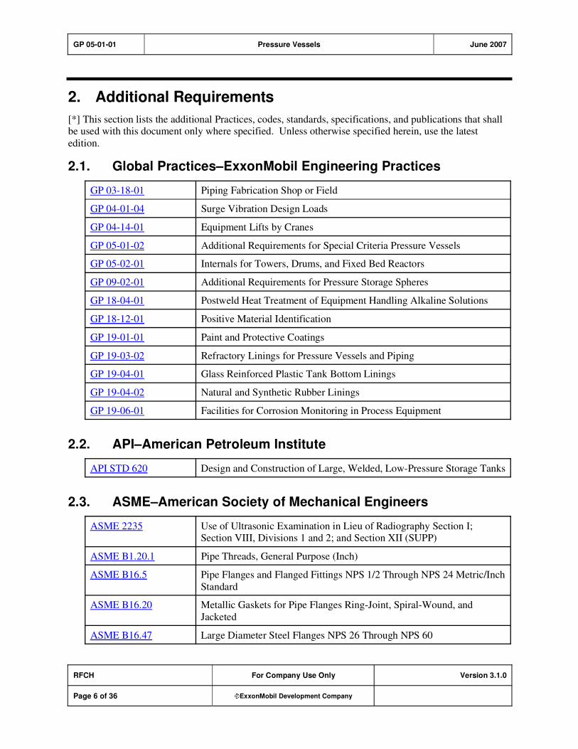
GP 05-01-01 Pressure Vessels June 2007
RFCH For Company Use Only Version 3.1.0
Page 6 of 36 ExxonMobil Development Company
2. Additional Requirements
[*] This section lists the additional Practices, codes, standards, specifications, and publications that shall be used with this document only where specified. Unless otherwise specified herein, use the latest
edition.
2.1. Global Practices–ExxonMobil Engineering Practices
GP 03-18-01 Piping Fabrication Shop or Field
GP 04-01-04 Surge Vibration Design Loads
GP 04-14-01 Equipment Lifts by Cranes
GP 05-01-02 Additional Requirements for Special Criteria Pressure Vessels
GP 05-02-01 Internals for Towers, Drums, and Fixed Bed Reactors
GP 09-02-01 Additional Requirements for Pressure Storage Spheres
GP 18-04-01 Postweld Heat Treatment of Equipment Handling Alkaline Solutions
GP 18-12-01 Positive Material Identification
GP 19-01-01 Paint and Protective Coatings
GP 19-03-02 Refractory Linings for Pressure Vessels and Piping
GP 19-04-01 Glass Reinforced Plastic Tank Bottom Linings
GP 19-04-02 Natural and Synthetic Rubber Linings
GP 19-06-01 Facilities for Corrosion Monitoring in Process Equipment
2.2. API–American Petroleum Institute
API STD 620 Design and Construction of Large, Welded, Low-Pressure Storage Tanks
2.3. ASME–American Society of Mechanical Engineers
ASME 2235 Use of Ultrasonic Examination in Lieu of Radiography Section I; Section VIII, Divisions 1 and 2; and Section XII (SUPP)
ASME B1.20.1 Pipe Threads, General Purpose (Inch)
ASME B16.5 Pipe Flanges and Flanged Fittings NPS 1/2 Through NPS 24 Metric/Inch
Standard
ASME B16.20 Metallic Gaskets for Pipe Flanges Ring-Joint, Spiral-Wound, and
Jacketed
ASME B16.47 Large Diameter Steel Flanges NPS 26 Through NPS 60

GP 05-01-01 Pressure Vessels June 2007
RFCH For Company Use Only Version 3.1.0
Page 7 of 36 ExxonMobil Development Company
ASME SEC I BPVC Section I - Rules for Construction of Power Boilers
ASME SEC VIII D1 BPVC Section VIII - Rules for Construction of Pressure Vessels - Division 1
ASME SEC VIII D1
MA APP 2
Mandatory Appendix 2 Rules for Bolted Flange Connections with Ring
Type Gaskets
ASME SEC VIII D2 BPVC Section VIII - Rules for Construction of Pressure Vessels - Division 2 Alternative Rules
Pressure Vessels and Piping, Stresses in Large Horizontal Pressure Vessels, Pressure Vessel and
Piping: Design and Analysis, Vol. II: 1977.
2.4. ASTM–American Society for Testing and Materials
ASTM F 436 Standard Specification for Hardened Steel Washers
ASTM F 436M Standard Specification for Hardened Steel Washers (Metric)
2.5. BSI–British Standards Institute
BSI BS EN 13445 Unfired Pressure Vessels
2.6. WRC–Welding Research Council
WRC BUL 107 Local Stresses in Spherical Cylindrical Shells Due to External Loadings
WRC BUL 297 Local Stresses in Cylindrical Shells Due to External Loading on
Nozzles-Supplement to WRC Bulletin No. 107
3. Definitions
Term [I] Description
hydrogen service See GP 18-10-01 for definition.
MAWP Maximum Allowable Working Pressure (MAWP) is the maximum
allowable pressure at the design temperature in the corroded condition. MAWP is determined by calculation, using the actual thickness less the
corrosion allowance, in accordance with ASME SEC VIII D1, Paragraph
UG-98.
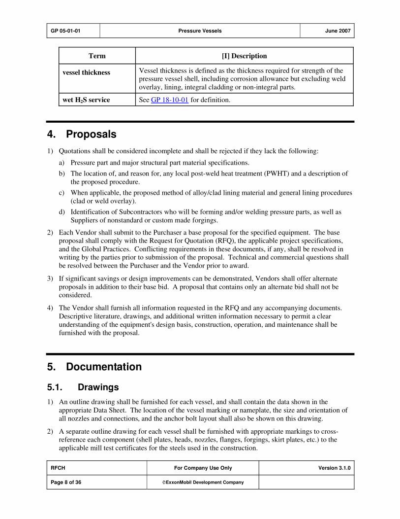
GP 05-01-01 Pressure Vessels June 2007
RFCH For Company Use Only Version 3.1.0
Page 8 of 36 ExxonMobil Development Company
Term [I] Description
vessel thickness Vessel thickness is defined as the thickness required for strength of the pressure vessel shell, including corrosion allowance but excluding weld
overlay, lining, integral cladding or non-integral parts.
wet H2S service See GP 18-10-01 for definition.
4. Proposals
1) Quotations shall be considered incomplete and shall be rejected if they lack the following:
a) Pressure part and major structural part material specifications.
b) The location of, and reason for, any local post-weld heat treatment (PWHT) and a description of
the proposed procedure.
c) When applicable, the proposed method of alloy/clad lining material and general lining procedures
(clad or weld overlay).
d) Identification of Subcontractors who will be forming and/or welding pressure parts, as well as
Suppliers of nonstandard or custom made forgings.
2) Each Vendor shall submit to the Purchaser a base proposal for the specified equipment. The base proposal shall comply with the Request for Quotation (RFQ), the applicable project specifications,
and the Global Practices. Conflicting requirements in these documents, if any, shall be resolved in writing by the parties prior to submission of the proposal. Technical and commercial questions shall
be resolved between the Purchaser and the Vendor prior to award.
3) If significant savings or design improvements can be demonstrated, Vendors shall offer alternate
proposals in addition to their base bid. A proposal that contains only an alternate bid shall not be considered.
4) The Vendor shall furnish all information requested in the RFQ and any accompanying documents.
Descriptive literature, drawings, and additional written information necessary to permit a clear
understanding of the equipment's design basis, construction, operation, and maintenance shall be furnished with the proposal.
5. Documentation
5.1. Drawings
1) An outline drawing shall be furnished for each vessel, and shall contain the data shown in the
appropriate Data Sheet. The location of the vessel marking or nameplate, the size and orientation of
all nozzles and connections, and the anchor bolt layout shall also be shown on this drawing.
2) A separate outline drawing for each vessel shall be furnished with appropriate markings to cross-reference each component (shell plates, heads, nozzles, flanges, forgings, skirt plates, etc.) to the
applicable mill test certificates for the steels used in the construction.
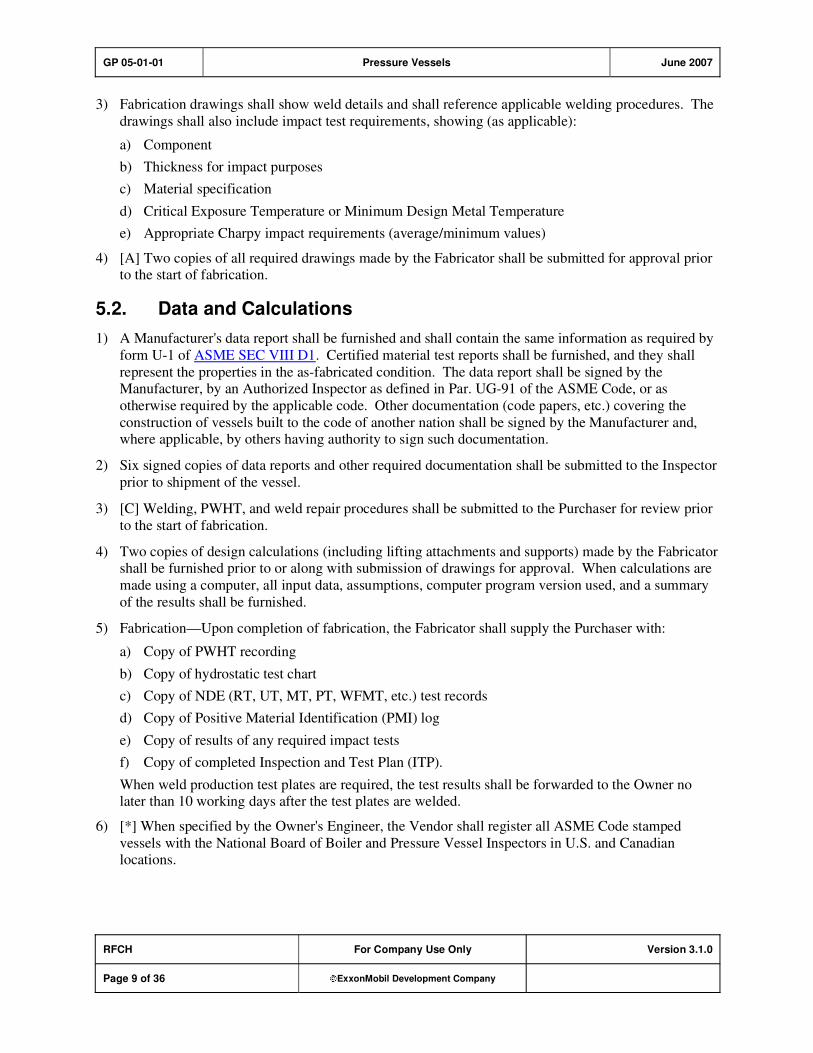
GP 05-01-01 Pressure Vessels June 2007
RFCH For Company Use Only Version 3.1.0
Page 9 of 36 ExxonMobil Development Company
3) Fabrication drawings shall show weld details and shall reference applicable welding procedures. The
drawings shall also include impact test requirements, showing (as applicable):
a) Component
b) Thickness for impact purposes
c) Material specification
d) Critical Exposure Temperature or Minimum Design Metal Temperature
e) Appropriate Charpy impact requirements (average/minimum values)
4) [A] Two copies of all required drawings made by the Fabricator shall be submitted for approval prior to the start of fabrication.
5.2. Data and Calculations
1) A Manufacturer's data report shall be furnished and shall contain the same information as required by
form U-1 of ASME SEC VIII D1. Certified material test reports shall be furnished, and they shall
represent the properties in the as-fabricated condition. The data report shall be signed by the Manufacturer, by an Authorized Inspector as defined in Par. UG-91 of the ASME Code, or as
otherwise required by the applicable code. Other documentation (code papers, etc.) covering the
construction of vessels built to the code of another nation shall be signed by the Manufacturer and, where applicable, by others having authority to sign such documentation.
2) Six signed copies of data reports and other required documentation shall be submitted to the Inspector
prior to shipment of the vessel.
3) [C] Welding, PWHT, and weld repair procedures shall be submitted to the Purchaser for review prior
to the start of fabrication.
4) Two copies of design calculations (including lifting attachments and supports) made by the Fabricator shall be furnished prior to or along with submission of drawings for approval. When calculations are
made using a computer, all input data, assumptions, computer program version used, and a summary
of the results shall be furnished.
5) Fabrication—Upon completion of fabrication, the Fabricator shall supply the Purchaser with:
a) Copy of PWHT recording
b) Copy of hydrostatic test chart
c) Copy of NDE (RT, UT, MT, PT, WFMT, etc.) test records
d) Copy of Positive Material Identification (PMI) log
e) Copy of results of any required impact tests
f) Copy of completed Inspection and Test Plan (ITP).
When weld production test plates are required, the test results shall be forwarded to the Owner no later than 10 working days after the test plates are welded.
6) [*] When specified by the Owner's Engineer, the Vendor shall register all ASME Code stamped
vessels with the National Board of Boiler and Pressure Vessel Inspectors in U.S. and Canadian locations.
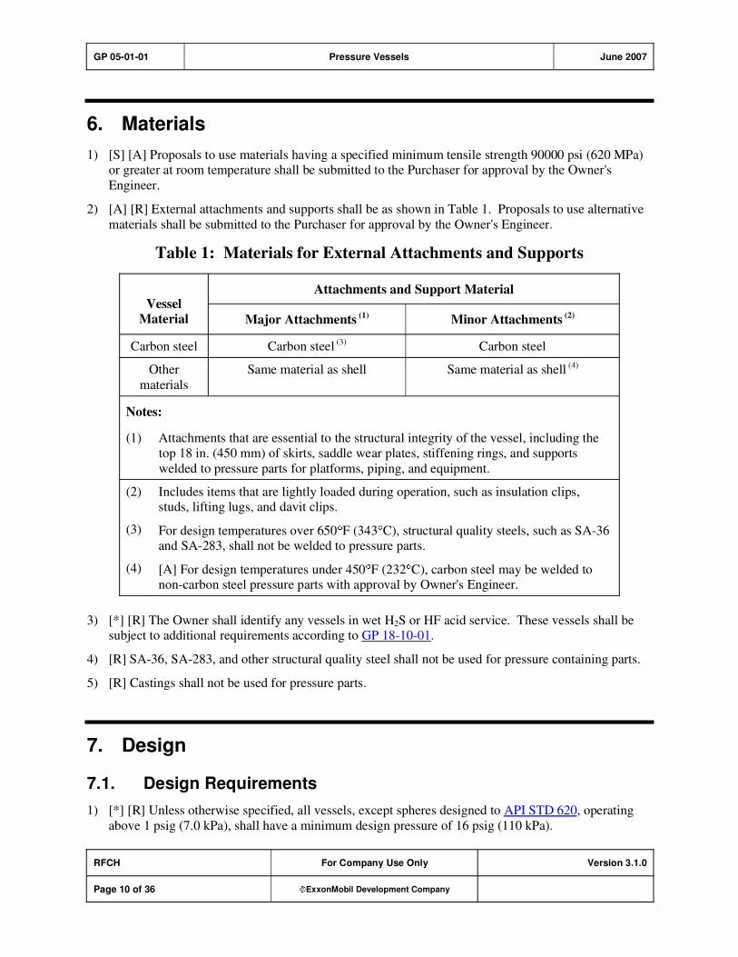
GP 05-01-01 Pressure Vessels June 2007
RFCH For Company Use Only Version 3.1.0
Page 10 of 36 ExxonMobil Development Company
6. Materials
1) [S] [A] Proposals to use materials having a specified minimum tensile strength 90000 psi (620 MPa) or greater at room temperature shall be submitted to the Purchaser for approval by the Owner's
Engineer.
2) [A] [R] External attachments and supports shall be as shown in Table 1. Proposals to use alternative
materials shall be submitted to the Purchaser for approval by the Owner's Engineer.
Table 1: Materials for External Attachments and Supports
Attachments and Support Material Vessel
Material Major Attachments (1) Minor Attachments (2)
Carbon steel Carbon steel (3) Carbon steel
Other
materials
Same material as shell Same material as shell (4)
Notes:
(1) Attachments that are essential to the structural integrity of the vessel, including the
top 18 in. (450 mm) of skirts, saddle wear plates, stiffening rings, and supports
welded to pressure parts for platforms, piping, and equipment.
(2) Includes items that are lightly loaded during operation, such as insulation clips, studs, lifting lugs, and davit clips.
(3) For design temperatures over 650 F (343 C), structural quality steels, such as SA-36 and SA-283, shall not be welded to pressure parts.
(4) [A] For design temperatures under 450 F (232 C), carbon steel may be welded to non-carbon steel pressure parts with approval by Owner's Engineer.
3) [*] [R] The Owner shall identify any vessels in wet H2S or HF acid service. These vessels shall be subject to additional requirements according to GP 18-10-01.
4) [R] SA-36, SA-283, and other structural quality steel shall not be used for pressure containing parts.
5) [R] Castings shall not be used for pressure parts.
7. Design
7.1. Design Requirements
1) [*] [R] Unless otherwise specified, all vessels, except spheres designed to API STD 620, operating
above 1 psig (7.0 kPa), shall have a minimum design pressure of 16 psig (110 kPa).
GP 05-01-01 Pressure Vessels June 2007
RFCH For Company Use Only Version 3.1.0
Page 11 of 36 ExxonMobil Development Company
2) [*] The Owner's Engineer shall specify the design pressure and temperature, design liquid level
(including fluidized and bulk solids), specific gravity, and/or design pressure at various elevations.
The Manufacturer shall design the vessel for the specified design pressure, liquid level, and temperature.
3) [*] [R] All vessels shall be stamped for their MAWP at the design temperature unless otherwise
specified by the Owner's Engineer. Nozzle reinforcement, cone-to-cylinder junction reinforcement,
and saddle support designs shall not be limiting factors in determining the MAWP.
4) [S] [R] Vessels for vacuum service, including those in which a vacuum may be created inadvertently,
shall be designed for an external pressure differential of 15 psi (103 kPa) or an external pressure
differential 25 percent greater than the maximum operating value, whichever is less.
5) [R] Jacketed vessels—Vessel and jacket shall be designed for the most severe condition of coincident pressure and temperature.
6) For purposes of determining the applicability of GP 05-01-02, thickness is defined as the thickness
"as ordered," provided the plates actually supplied meet the ASTM tolerances on thickness (weight).
Vessel pressure components or sections which are greater than 2 in. (50 mm) in thickness shall meet the Examination and Testing requirements of GP 05-01-02. In addition, nozzle forgings for insertion
into shell plates greater than 2 in. (50 mm) thick shall also meet the Nozzle and Connections design
requirements of GP 05-01-02.
Weld overlay, lining, integral cladding, non-integral parts, flat heads and closures, tubesheets, flanges, nozzle/manway reinforcing pads, areas of reinforcement, and areas of over-thickness up to 12
percent in excess of the specified thickness provided for plate thinning during forming or scale losses
during heating, need not be considered in determining the applicability of GP 05-01-02.
7.2. Design Loads
1) [A] [R] Loadings to be considered in designing a vessel shall be according to ASME SEC VIII and
shall include cyclic conditions and erection loadings. If the vessel will be subjected to more than
1000 cycles in which the pressure range is greater than 80 percent of the design pressure, or where the
temperature range is greater than 350 F (195 C), an assessment of the need for a fatigue analysis shall be conducted according to the ASME SEC VIII D2, Par. AD-160, or with approval by the
Owner's Engineer, according to the recognized code used for design and fabrication. If a fatigue
analysis is required, then vessel is considered to be in cyclic service and is subject to additional
requirements of GP 05-01-02.
2) [R] Additional loadings—Vessels containing circulating suspensions of solids in fluids (fluid-solids processes) shall be subjected to additional horizontal loadings according to GP 04-01-04.
3) [S] During erection, testing, startup, or operation, all applicable loads shall be considered as acting
simultaneously, including either wind or earthquake, whichever governs. These loads include, but are not limited to:
a) Empty dead load of the vessel, attached piping and equipment.
b) Empty dead weight of the vessel, trays, insulation, internal attachments, ladder, platforms, and
external piping.
See GP 04-01-03 for additional loading requirements.
GP 05-01-01 Pressure Vessels June 2007
RFCH For Company Use Only Version 3.1.0
Page 12 of 36 ExxonMobil Development Company
7.3. Vibration Analysis
1) [R] All towers taller than 100 ft (30 m) with a H/D ratio greater than 15 shall be investigated for susceptibility to wind induced vibration (WIV)
Where: H = Overall Height ft (m)
D = Average shell diameter of top 1/3 height of tower ft. (m)
2) WIV are unlikely for any of the following conditions and no further analysis is required. These
conditions shall be checked for all; erection, empty (shutdown or non-operating) and normal
operating conditions.
a) Vc < 0.25V or Vc > 1.2V
b) m' > 1.1
c) m' > 0.8 and f > 1.1
Where: V = Mean hourly wind speed, mph (km/h)
Vc = Critical Wind Velocity, mph (km/h)
m' = Mass Damping Parameter = m / d2
m = mass per unit length over the top third of the vessel lb/ft (kg/m)
= Structural Damping Fraction of Critical (0.004 unless other values are justified)
= Density of air (typically 0.078 lbs/ft3 or 1.25 kg/m
3)
f = fundamental natural frequency of the tower, cycles/second
d = mean wind diameter over the top third of the tower, ft (m)
3) If none of the conditions in Item (2), above, is satisfied, WIV is suspected and the following
mitigation steps shall be considered:
a) Flare skirt to increase the natural frequency
b) Increase the thickness of top sections to increase the critical speed.
c) If WIV is suspected in erection condition, only mitigation using temporary guy wires could be
considered.
d) If WIV is suspected in operating condition, the permanent mitigation is required. Proposal to
allow credit for additional damping due to operating liquid on trays or to adopt a Tuned mass
damper method, or other methods shall be discussed with the owner's engineer.
e) If WIV is suspected in empty condition, alternate solutions including fatigue analysis are
acceptable.
4) [A] Fatigue analysis, if required, shall be performed using method described in Pressure Vessel Design Handbook by H. H. Bednar, 2nd edition (Van Nostrand Reinhold Co. N.Y.) and the
following. Any other method of analysis may be used with approval by Owner's Engineer.
The dynamic wind load F shall be applied to the top of the structure as an equivalent static point load, where
F = 0.00086(Cl x MF.)(D x H x Vc2), Lbs

GP 05-01-01 Pressure Vessels June 2007
RFCH For Company Use Only Version 3.1.0
Page 13 of 36 ExxonMobil Development Company
F = 0.016(Cl x MF.)(D x H x Vc2), N
Where: Cl = Lift Coefficient (greater than or equal to 0.4)
MF = Magnification factor (greater than or equal to 60)
D= Predominant outside steel shell diameter of the top one-third of the vessel, ft (m)
H = The total height of vessel from base of skirt to top of head, ft.(m)
a) The maximum single amplitude (deflection) at the top of the vessel due to dynamic wind load,
including rotation of the concrete foundation or structure, shall not exceed 0.5 percent of H.
b) The allowable fatigue stress shall be the lesser of the following:
i) Allowable fatigue stress based on ASME SEC VIII D2 MA APP 5 (for the number of cycles
to failure as calculated in the wind dynamic analysis)
and
ii) )MPa(k
T131Sor(psi)
k
T19000S
51
allowable
51
allowable
Where: T = natural period (seconds) and k = stress concentration factor.
The value of k shall be no less than 2 for penetration welded joints and no less than 3 for
non-penetration welded joints.
c) [A] All calculations shall be submitted for approval prior to fabrication.
7.4. Allowable Stresses
1) [A] [R] The alternative higher stresses at temperature for high alloy steels permitted by the ASME Code shall not be used for flanges of gasketed joints, or other applications where slight amounts of
distortion can cause leakage or malfunction, unless approved by the Owner's Engineer.
2) [R] Vessel supporting skirts—Allowable tensile and compressive stresses for vessel supporting skirts
shall be according to the code used for vessel design.
3) Anchor bolts—Allowable stress for anchor bolts shall be according to GP 04-06-01.
4) [S] In the hydrostatic test condition, the maximum membrane stress in the vessel shell shall not
exceed 90 percent of the specified minimum yield strength for ferritic steels, nor 100 percent of the
specified minimum yield strength for austenitic and duplex steels or non-ferrous materials.
7.5. Vessel Thickness
1) [M] [R] The following additional criteria shall be considered in calculating the required thickness of vessels and supports:
a) Horizontal drums on saddle supports shall be investigated for buckling, local circumferential
bending, and shear stresses.
L. P. Zic's method in the referenced "ASME: Pressure Vessels and Piping–Stresses in Large
Horizontal Pressure Vessels, Pressure Vessels and Piping, Design and Analysis, Vol. II," may be
used for this investigation.
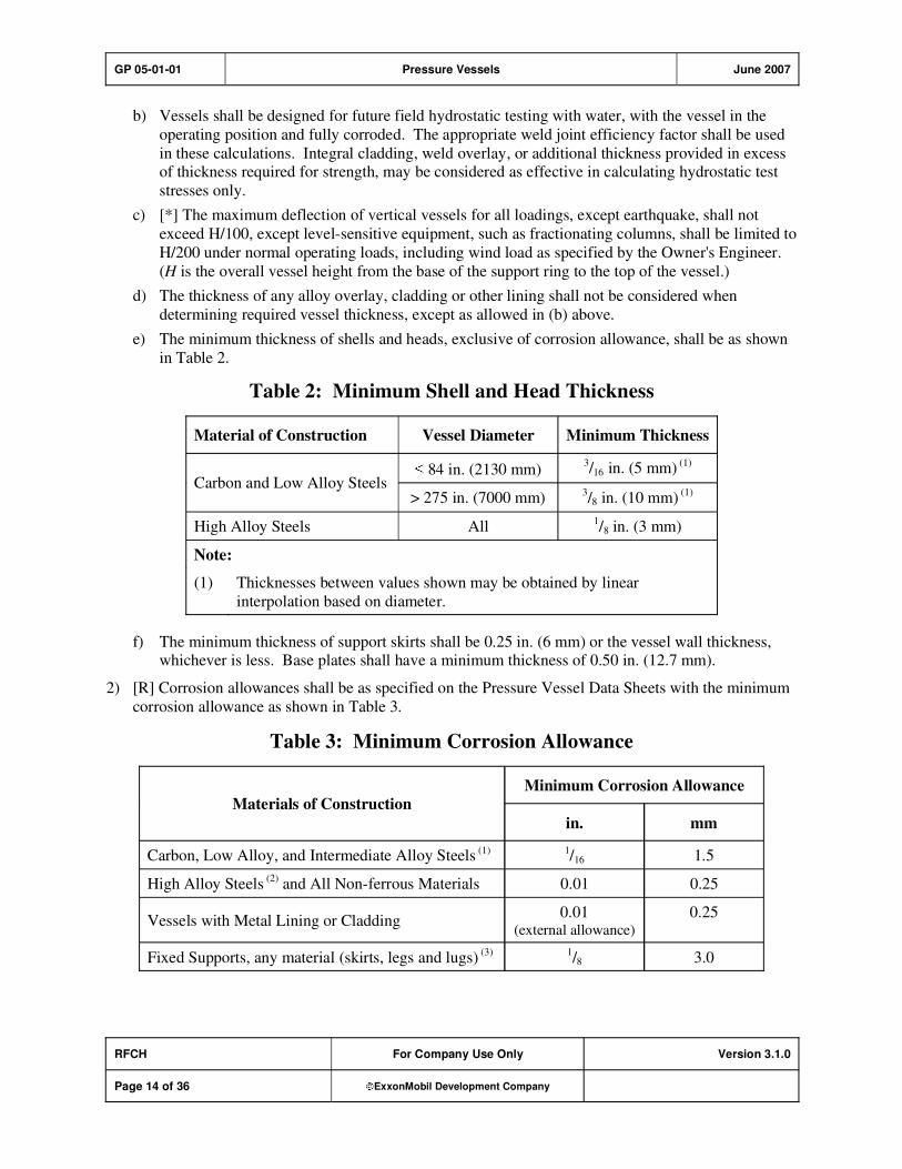
GP 05-01-01 Pressure Vessels June 2007
RFCH For Company Use Only Version 3.1.0
Page 14 of 36 ExxonMobil Development Company
b) Vessels shall be designed for future field hydrostatic testing with water, with the vessel in the
operating position and fully corroded. The appropriate weld joint efficiency factor shall be used
in these calculations. Integral cladding, weld overlay, or additional thickness provided in excess of thickness required for strength, may be considered as effective in calculating hydrostatic test
stresses only.
c) [*] The maximum deflection of vertical vessels for all loadings, except earthquake, shall not
exceed H/100, except level-sensitive equipment, such as fractionating columns, shall be limited to
H/200 under normal operating loads, including wind load as specified by the Owner's Engineer.
(H is the overall vessel height from the base of the support ring to the top of the vessel.)
d) The thickness of any alloy overlay, cladding or other lining shall not be considered when
determining required vessel thickness, except as allowed in (b) above.
e) The minimum thickness of shells and heads, exclusive of corrosion allowance, shall be as shown
in Table 2.
Table 2: Minimum Shell and Head Thickness
Material of Construction Vessel Diameter Minimum Thickness
84 in. (2130 mm) 3/16 in. (5 mm) (1)
Carbon and Low Alloy Steels > 275 in. (7000 mm)
3/8 in. (10 mm)
(1)
High Alloy Steels All 1/8 in. (3 mm)
Note:
(1) Thicknesses between values shown may be obtained by linear
interpolation based on diameter.
f) The minimum thickness of support skirts shall be 0.25 in. (6 mm) or the vessel wall thickness, whichever is less. Base plates shall have a minimum thickness of 0.50 in. (12.7 mm).
2) [R] Corrosion allowances shall be as specified on the Pressure Vessel Data Sheets with the minimum
corrosion allowance as shown in Table 3.
Table 3: Minimum Corrosion Allowance
Minimum Corrosion Allowance
Materials of Construction
in. mm
Carbon, Low Alloy, and Intermediate Alloy Steels (1) 1/16 1.5
High Alloy Steels (2)
and All Non-ferrous Materials 0.01 0.25
Vessels with Metal Lining or Cladding 0.01
(external allowance)
0.25
Fixed Supports, any material (skirts, legs and lugs) (3) 1
/8 3.0
GP 05-01-01 Pressure Vessels June 2007
RFCH For Company Use Only Version 3.1.0
Page 15 of 36 ExxonMobil Development Company
Minimum Corrosion Allowance
Materials of Construction
in. mm
Notes:
(1) Includes all steels with an alloy content not exceeding 9Cr 1Mo.
(2) Includes all steels with an alloy content of 12Cr or greater.
(3) Corrosion allowance indicated is total corrosion allowance.
7.6. Heads and Transition Sections
1) [R] Cylinder-to-cone transitions shall be toriconical sections when any of the following conditions apply:
2) The section is subject to a major support reaction (for example, skirt-to-cone attachment).
3) Cone apex angle exceeds 60 degrees.
4) [R] Inside radius of knuckles for torispherical heads, toriconical heads, or conical transition sections
where knuckles are required, shall be as follows:
5) For knuckles 3/4 in. (19 mm) thick or less, minimum inside radius shall be not less than 6 percent of
the outside diameter of the adjoining cylindrical section.
6) For knuckles thicker than 3/4 in., minimum inside radius shall be not less than 10 percent of the
outside diameter of the adjoining cylindrical section.
7) [A] [R] Intermediate heads shall be attached to the shell according to the ASME SEC VIII D1, Figure UW-13.1 (f) with fillet welds, unless otherwise approved by the Owner's Engineer.
7.7. Nozzles and Manways
7.7.1. General Requirements
1) [A] [R] Nozzles NPS 2 (50 mm) and larger shall be flanged or studded, and shall have the same P-
number as the vessel shell. Corrosion protection equivalent to that of the vessel shall be provided. Use of studded nozzles shall be approved by the Owner's Engineer.
2) [R] All nozzles and connections Class 900 and above shall be flanged or butt welded.
3) [*] [R] Unless otherwise specified, all instrument connections, including thermowell connections,
shall be a minimum of NPS 2 (50 mm) flanged.
4) [M] Nozzle projection shall be such that all flange bolting clears the vessel and any insulation by at
least the distance required to insert and operate a box wrench.
5) [A] [O] Connections shall not extend into the vessel beyond the interior surface except as required by
Item (6) below when specified or when approved by the Owner's Engineer.
6) [M] Nozzles in portions of vessels with gunite shall have internal projections so that the nozzle end is
flush with the lining.
GP 05-01-01 Pressure Vessels June 2007
RFCH For Company Use Only Version 3.1.0
Page 16 of 36 ExxonMobil Development Company
7) [*] [R] When used with spiral wound gaskets, the ID of forged nozzles, including long weldneck
flanged nozzles, shall be decreased as necessary to meet the requirements of Table 16 and Table 18 of
ASME B16.20. When specified, the ID of the nozzles shall match the ID of mating pipe flanges.
8) For skirt supported vessels, the following are not permitted within the skirt:
a) [S] Flanged connections
b) [M] [R] Bimetallic welds
9) [*] [R] Unlined carbon steel and low alloy (up to and including 9Cr-1Mo) pipe and fittings inside
vessel skirts shall be at least one schedule heavier than that required for the MAWP plus corrosion
allowance, unless otherwise specified by the Owner's Engineer.
10) [R] Nozzle boltholes shall straddle centerlines.
11) [A] Nozzles and manways shall be attached to the vessel by full penetration welds. Unless otherwise
approved by the Owner's Engineer, full penetration welds shall be used for attaching reinforcing pad
plates to nozzle and manway necks.
12) [R] Nozzles subjected to large forces and moments shall be analyzed for additional shell and nozzle neck reinforcement requirements. Stresses shall be limited to values listed in Figure 4-130.1 of
ASME SEC VIII D2 MA APP 4; the value of Sm shall be equal to the allowable stress listed in the
appropriate Division of ASME SEC VIII or in the recognized code to which the vessel is designed.
7.7.2. Connections NPS 11/2 and Smaller
1) [R] Connections NPS 11/2 (40 mm) and smaller may be threaded, except for pressure relief valve
connections. Couplings or integrally reinforced fittings shall be used for threaded connections. Additional thickness shall be provided for corrosion allowance, as required to provide corrosion
protection equivalent to that of the vessel. All couplings or fittings shall be installed with complete
penetration welds. Half couplings welded to the outer surface of the vessel may be used.
2) Threaded connections shall have tapered threads according to ASME B1.20.1.
3) Threaded and socketweld connections used as pressure parts shall be Class 6000 forged steel couplings.
4) [*] Connections NPS 11/2 (40 mm) and smaller shall be braced according to GP 03-18-01 when
specified by the Owner's Engineer.
5) [S] Plugs and caps for vent and drain connections that are used for hydrostatic testing and that could potentially result in leakage of dangerous material shall be seal welded. Vent and drain connections
that are frequently used shall be provided with valves complete with plugs or caps. Refer to GP 03-
18-01 for definition of dangerous material.
7.7.3. Nozzle Reinforcement
1) [R] Nozzle reinforcing pads, or segments thereof, shall be provided with a 1/4 in. (6 mm) diameter
NPT threaded telltale hole, which shall be filled with grease or plastic sealant after pressure testing.
2) [A] [R] Nozzles and their reinforcing pads shall not be located in the knuckle region of a torispherical head without the approval by Owner's Engineer.
3) [R] For unlined carbon steel vessels in HF service, integral reinforcement shall be used.
GP 05-01-01 Pressure Vessels June 2007
RFCH For Company Use Only Version 3.1.0
Page 17 of 36 ExxonMobil Development Company
4) [R] Pad reinforced nozzles are not permitted if the vessel shell design temperature is 800 F (427 C)or greater.
5) [R] When integral reinforcement is provided on nozzles 6 in. (150 mm) and greater on vessels with
design temperatures 800 F (427 C) or greater, the ratio of nozzle wall thickness to shell wall
thickness shall not be greater than 2.5, unless a detailed stress analysis has been performed.
7.7.4. Additional Requirements for Manways
1) [*] [M] Manways shall be provided for all process vessels with diameters larger than 36 in. (914
mm). Smaller vessels shall have handholes or flanged heads, or both, as specified. Manway and
handhole quantity and locations will be specified. Manways shall have a minimum clear inside diameter of 19 in. (480 mm).
2) Manway covers shall be hinged or provided with handling davits. If blind flanges to ASME B16.5
are used for cover plates, corrosion allowance shall be added to the thickness only in the amount that
the specified vessel corrosion allowance exceeds 1/4 in. (6 mm).
3) [A] [R] The design and use of quick opening closures shall be approved by the Owner's Engineer.
Detailed drawings and calculations, including safety devices, shall be submitted for approval.
7.7.5. Flanges
1) [R] Flanges NPS 24 and smaller (NPS 12 and smaller for Class 2500) shall be according to ASME B16.5.
2) [A] [R] Flanges larger than NPS 24 (600 mm) shall be according to ASME B16.47 Series B, unless
otherwise approved by the Owner's Engineer. Flanges outside the scope of ASME B16.47 shall be
designed according to ASME SEC VIII D1 (with allowable stresses as determined according to that Code), and subject to ASME SEC VIII D1 MA APP 2, Section 14 of that Code. The rigidity index, J,
shall be determined for the flange at the seating and design conditions. For carbon steel vessels with
design temperature 700 F (370 C) or lower and for low alloy steel (up to and including 5Cr-1Mo)
vessels with design temperature 850 F (454 C) or less, J shall be limited to 0.9.
3) [R] Flanges for nozzles with attached piping—Flanges that are not according to ASME B16.5 or
ASME B16.47 shall be designed to include the applied bending moment from the attached piping.
4) [C] [R] The design temperature of uninsulated external flanges and their gaskets may be reduced to
90 percent of the design temperature of the vessel components to which they are attached provided they are located in exposed open areas and this is permitted by the vessel design code. The
corresponding bolting design temperature may be reduced to 80 percent of the vessel design
temperature. These temperature reductions shall not be applied to flanged shell girth joints.
5) [A] [R] Lap type flanges shall not be used unless approved by the Owner's Engineer.
6) [R] Slip-on flanges shall be positioned so that the distance from the face of the flange to the pipe end
is equal to the nominal pipe wall thickness, plus approximately 1/8 in. (3 mm). The welds shall be
applied in a manner that will not require refacing of the flange.
7.8. Vents
1) [S] [A] A vent shall be provided at or near the top of the vessel on all vessels with manways to facilitate adequate ventilation during vessel entry. Vent shall be sized based on vessel volume and
shall not be less than 6 in. diameter. The vent may be another manway or, when approved by the
GP 05-01-01 Pressure Vessels June 2007
RFCH For Company Use Only Version 3.1.0
Page 18 of 36 ExxonMobil Development Company
Owner's Engineer, a flanged process nozzle which can be disconnected at the vessel and the piping
removed to create a clear path. On horizontal vessels, the vent and manway shall be on opposite ends
of the vessel.
7.9. Vessel Supports and Attachments
7.9.1. Horizontal Vessel Supports
1) [A] [R] Unless approved by the Owner's Engineer, horizontal vessels shall be supported on two
saddles covering at least 120 degrees of the vessel circumference. Saddles and pads shall not cover vessel shell seams. One of the saddle bearing plates shall have slotted holes to allow for thermal
expansion of the vessel. If more than two saddles are used, allowable differential settlement shall be
determined and actual settlement measurements made periodically to assure the vessel is not overstressed or spring support be considered.
2) [M] Horizontal vessels supported on concrete saddles or steel saddles not fully welded to the vessel
shall be provided with corrosion plates between the saddle and the vessel. These plates shall be 1/4 in.
(6 mm) thick, shall extend at least 2 in. (50 mm) beyond the periphery of the bearing area of the saddle, and shall be seal-welded to the vessel. Plates shall have the same nominal chemical
composition as the vessel. A 1/4-in. (6-mm) vent hole shall be provided in each corrosion plate, and
the hole shall be plugged with a sealant after the vessel has been pressure tested.
7.9.2. Vertical Vessel Supports
1) [R] Vertical vessels subject to vibration, for example, reciprocating compressor suction drums (that
are not machine mounted), shall be skirt-supported on a solid or continuous concrete base.
2) [R] Vessels subject to surge vibration design loads according to GP 04-01-04 shall be skirt supported
with skirt detail according to the requirements of the Vessel Support Section of GP 05-01-02.
3) [R] Vertical vessels shall be provided with one of the following types of supports designed to withstand the loading described in the Design Loads section of this Global Practice.
a) [*] Lugs or legs welded directly to the shell—An analysis of the support-to-shell junctions shall be conducted to determine the need for additional reinforcement of the shell. Maximum stress
intensity limits for the load combinations shall be in accordance with AD-150 of ASME SEC
VIII D2, except that fatigue life evaluations are not required unless specified by the Owner's Engineer. Stresses listed in Figure 4-130.1 of ASME SEC VIII D2 MA APP 4 shall be limited to
the following, unless detailed nonlinear limit load analysis is performed in accordance with
ASME SEC VIII D2 MA APP 4:
i) The local membrane stress should not exceed 1.5 Sm.
ii) The stress due to the sum of membrane and bending stresses should not exceed 2.25Sm.
Where Sm is equal to the allowable stress listed for the material in the appropriate Division of
ASME SEC VIII or in the recognized code to which the vessel is designed.
b) Support skirts welded to the shell or head—Considerations and general design shall be in
accordance with ASME SEC VIII D1 NMA APP G. Joint efficiency of attachment welds shall
be according to code requirements.
4) [M] A single skirt access manway, of 20 in. (500 mm) diameter, shall be provided if piping is located
inside the skirt, unless access is available from below the skirt (e.g., vessels located in a structure).
No piping shall pass through access openings.
GP 05-01-01 Pressure Vessels June 2007
RFCH For Company Use Only Version 3.1.0
Page 19 of 36 ExxonMobil Development Company
5) [R] Skirt vents and access shall be provided if the vessel is internally insulated and operated at a fluid
temperature above 500 F (260 C). At least four vents shall be provided. The vents shall be
minimum NPS 6 (150 mm), Schedule 80 (10.97 mm wall) pipe sleeves, and shall be equally spaced at
a maximum of 6 ft (1800 mm) around the skirt circumference.
6) [S] [*] Skirt openings for piping shall have a 1/2 in. (13 mm) maximum clearance between the pipe
OD, including insulation, and the skirt, when the inside of the skirt is not to be fireproofed.
7) [*] [M] If the skirt is specified by the Owner's Engineer to be fireproofed, the vents and access hole
sleeves shall be of sufficient length so that the ends will be flush with the inner and outer surfaces of
the finished fireproofing.
7.9.3. Attachments
1) [R] Reinforcing pads for internal or external structural attachments to vessel shells shall be provided
with a 1/4-in. (6-mm) diameter vent hole for the enclosed space between welds located at or near the
low point of the pad. External vent holes shall be plugged with grease or plastic sealant after the
vessel has been tested.
2) [R] Stiffening and insulation rings on parts of vertical vessels in intermittent service or with normal
operating temperatures below 300 F (149 C) shall be designed to allow for drainage.
3) [R] When corrosion allowance (CA) is greater than 0.1 in. (2.5 mm), welded non-pressure
attachments inside carbon and low-alloy steel vessels shall be completely welded to prevent corrosion behind the attachment. Intermittent welding may be used in non-corrosive services (CA less than or
equal to 0.1 in. [2.5 mm]) and in high-alloy and alloy-lined vessels where seal welding is not
required.
4) [*] [R] The vessel Fabricator shall provide lifting and tailing lugs as specified. Erection loadings and analysis shall conform to the following for the vessel shell, skirt, and attachments welded to the
vessel shell or skirt that are purpose designed for the lift:
a) [A] For lifts of 100 tons or less, a lift load factor of 1.7 shall be used along with normal code allowable stress levels, unless otherwise approved by the Owner's Engineer.
b) [A] For lifts greater than 100 tons, a lift load factor of 1.35 shall be used along with normal code
allowable stress levels, if approved by the Owner's Engineer.
The above load factors are minimum values and shall be increased as necessary to account for
actual lifting procedures and equipment.
c) Vessel shells shall be analyzed for local buckling, bending, and shear imposed during erection.
Analysis may be performed in accordance with WRC BUL 107 or WRC BUL 297, as applicable.
d) The allowable stresses shall be as follows:
i) Stresses in the shell and attachments shall be categorized according to ASME SEC VIII D2
MA APP 4 except that the bending stress shall be considered as primary unless detailed
nonlinear limit load analysis is performed in accordance with ASME SEC VIII D2 MA APP 4. Basic allowable stress shall be limited to the values listed in the applicable code.
Allowable stresses for attachment welds shall be reduced by the applicable joint efficiency
factor.
ii) No increase in allowable stress is permitted due to the short duration of the erection loads.
e) [S] [A] The use of bolted-on tailing frames shall be approved by the Owner's Engineer and shall comply with GP 04-14-01 and the following requirements:
GP 05-01-01 Pressure Vessels June 2007
RFCH For Company Use Only Version 3.1.0
Page 20 of 36 ExxonMobil Development Company
i) The fit-up tolerances between the tailing frame and the vessel skirt shall be taken into account
in determining the shear loads and load distribution on the attachment bolting during lifting.
ii) The deflection of the vessel skirt during the lift shall not impose any additional shear loads on the attachment bolting.
iii) Bolted connections shall be control-bolted to ensure that the loads are distributed to the bolt connections.
7.10. Proprietary Construction
1) [A] [C] Alternatives to solid wall construction. Certain forms of construction may be used as an alternative to conventional solid wall construction, provided they meet the requirements of this
practice, and approval by the Owner's Engineer has been obtained prior to submitting a proposal for
such construction.
The alternatives shall be as follows:
a) Spiral wound
b) Band reinforced
c) Multiple layer
8. Additional Requirements for Flanged Shell Girth Joints
1) [A] [R] Flanged girth joints shall be designed for through bolting. Proposals for alternative joint
design shall be submitted to the Purchaser for approval by the Owner' Engineer.
2) [R] Flanges for girth joints shall conform to the following:
a) Flanges shall be according to ASME B16.5, ASME B16.47 Series B, or designed according to
ASME SEC VIII D1 with allowable stresses determined according to that code.
b) Welding neck flanges shall be used where the pressure-temperature design conditions require an
ASME Class 300 or greater flange.
c) Slip-on flanges shall not be used if any of the following conditions are exceeded:
i) Pressure-temperature design conditions require an ASME Class 300 or greater flange.
ii) Design temperature exceeds 750 F (400 C).
iii) Specified corrosion allowance for the vessel is greater than 1/8 in. (3 mm).
iv) The vessel is in hydrogen service.
d) Girth flanges larger than NPS 24 that are not in accordance with ASME B16.47 Series B shall be designed to meet the flange rigidity recommendations in ASME SEC VIII D1 MA APP 2,
Section 14. The rigidity index, J, shall be determined for the flange at the seating and design
conditions. For carbon steel vessels with design temperature 700 F (370 C) or lower and for low
alloy steel (up to and including 5Cr-1Mo) vessels with design temperature 850 F (454 C) or less, J shall be limited to 0.9.
3) [*] [R] Unless otherwise specified, gasket contact surfaces shall have a finish equivalent to 125 to 250
in. (3.2 to 6.3 m) roughness average (Ra).
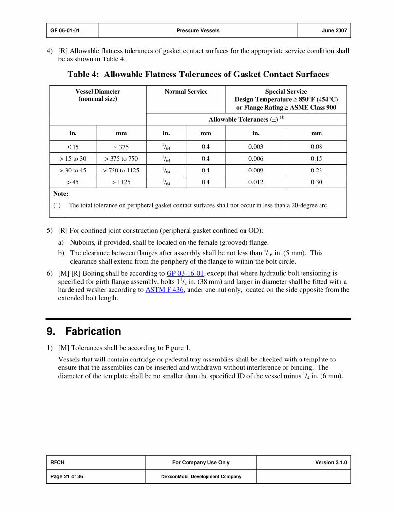
GP 05-01-01 Pressure Vessels June 2007
RFCH For Company Use Only Version 3.1.0
Page 21 of 36 ExxonMobil Development Company
4) [R] Allowable flatness tolerances of gasket contact surfaces for the appropriate service condition shall
be as shown in Table 4.
Table 4: Allowable Flatness Tolerances of Gasket Contact Surfaces
Normal Service Special Service
Design Temperature 850 F (454 C)
or Flange Rating ASME Class 900
Vessel Diameter
(nominal size)
Allowable Tolerances ( )(1)
in. mm in. mm in. mm
15 375 1/64 0.4 0.003 0.08
> 15 to 30 > 375 to 750 1/64 0.4 0.006 0.15
> 30 to 45 > 750 to 1125 1/64 0.4 0.009 0.23
> 45 > 1125 1/64 0.4 0.012 0.30
Note:
(1) The total tolerance on peripheral gasket contact surfaces shall not occur in less than a 20-degree arc.
5) [R] For confined joint construction (peripheral gasket confined on OD):
a) Nubbins, if provided, shall be located on the female (grooved) flange.
b) The clearance between flanges after assembly shall be not less than 3/16 in. (5 mm). This
clearance shall extend from the periphery of the flange to within the bolt circle.
6) [M] [R] Bolting shall be according to GP 03-16-01, except that where hydraulic bolt tensioning is
specified for girth flange assembly, bolts 11/2 in. (38 mm) and larger in diameter shall be fitted with a
hardened washer according to ASTM F 436, under one nut only, located on the side opposite from the extended bolt length.
9. Fabrication
1) [M] Tolerances shall be according to Figure 1.
Vessels that will contain cartridge or pedestal tray assemblies shall be checked with a template to ensure that the assemblies can be inserted and withdrawn without interference or binding. The
diameter of the template shall be no smaller than the specified ID of the vessel minus 1/4 in. (6 mm).

GP 05-01-01 Pressure Vessels June 2007
RFCH For Company Use Only Version 3.1.0
Page 22 of 36 ExxonMobil Development Company
Figure 1: Pressure Vessel Tolerances
1 Tolerance on longitudinal dimensions from the reference plane shall be thesmaller of 1/64 in. per foot of length or 1/2 in., unless noted otherwise.
2 Reference Plane punch mark inside and out 3 in. from root landof bottom course.
3 Flange face of nozzle from centerline of vessel ± 1/8 in.
4 Flange face of nozzle shall be parallel with the indicated plane in anydirection ± 1/2°, but not to exceed 3/16 in.
5 Location of nozzle from reference plane ± 1/4 in.; exception shall be liquidlevel controller nozzles ± 1/16 in. and nozzles related to tray, draw-off pans,etc., so dimensioned on drawings, distance from support ring ± 1/8 in.
6 Flange face of manhead from outside of tower ± 1/4 in.
7 Flange face of manhead shall be parallel with the indicated plane in anydirection ± 1°.
8 Location of manhead from reference plane ± 1/2 in.
9 Flange face of top or bottom nozzle to reference plane ± 1/4 in.
10 Orientation of nozzle and other attachments shall be within ± 1/8 in.
11 1/8 in. max. lateral translation.
12 1/16 in. max. rotation of flanges from the indicated position, measured asshown.
13 In addition to ASME code tolerances, tolerances from nominal inside shelldiameter as measured by external strapping shall be as given in tablebelow.
14 Maximum deviation from straight applied to shell shall be: 1/8 in. in any 10 ftor 1/2 in. per 50 ft of length. In addition, distortion caused by welding oflongitudinal or circumferential joints shall not exceed 1/4 in. maximum depthin a 36 in. length of shell centered on the weld.
15 Distance from reference plane to base + 0 in., - 1/4 in. or lug + 1/4 in., 0 in.
16 Base or support lug out of level over any diameter shall be as given in tablebelow.
17 Bolt hole circle tolerance shall be as given in table below.10
> 16 ft - 0 in.
± 5/16 in.
± 1/4 in.
± 1/4 in.
> 7 ft - 0 in. to
16 ft - 0 in.
± 1/4 in.
± 1/4 in.
± 1/4 in.
> 4 ft - 0 in. to
7 ft - 0 in.
± 3/16 in.
± 3/16 in.
± 1/8 in.
< 4 ft - 0 in.
± 1/8 in.
± 1/8 in.
± 1/8 in.
13
16
17
ITEM
NUMBER
INSIDE DIAMETER SPECIFIED
16
15
13
3
4
6
2
17
Weld Line
Tangent Line
14
7
5
8
9
1

GP 05-01-01 Pressure Vessels June 2007
RFCH For Company Use Only Version 3.1.0
Page 23 of 36 ExxonMobil Development Company
Figure 1 Continued
ACCEPTABLE METRIC EQUIVALENTS
in.
1/16
1/8
3/16
5/16
1/4
1/2
mm
1.5
3
5
8
6
13
ft
4
7
16
mm
1200
2100
4800
1/64 in. per ft
1/8 in. in any 10 ft
1/2 in. per 50 ft
0.4 mm per 300 mm
3 mm in any 3,000 mm
13 mm per 15,000 mm
12
11Nozzle Flange
Longitudinal CenterLine of Vessel or
Design Location
Weld
18 Distance from reference plane to the centerline of the saddle 1/8 in. (3 mm).
19 Distance between the centerline of the saddle 1/8 in. (3 mm).
20 Distance between the centerline of the support bolt holes across width 1/8 in.(3 mm).
21 Saddle base plate out of level shall be the same as for item 16.
22 Saddle base plate out of level slope 1/16 in. (1.5 mm), across the width of the saddle.
23 Location of nozzle from vessel centerline 1/4 in. (6 mm).
Tangent
2120
18 19
13
2
8
1
6
233
4
5
22
GP 05-01-01 Pressure Vessels June 2007
RFCH For Company Use Only Version 3.1.0
Page 24 of 36 ExxonMobil Development Company
2) [R] When a vessel is insulated for cold service, the vessel nameplate shall be insulated, and a
duplicate nameplate shall be provided by the Fabricator for later installation over the outside surface
of the insulation system.
3) [R] No stamping or indentations shall be made directly on a vessel after PWHT, but may be placed on
a plate welded to the vessel before PWHT. The vessel shall be stenciled to show it has undergone
PWHT, and that no further welding is to be done on the vessel.
4) Vessel nameplates shall be corrosion-resistant and shall extend beyond the vessel by the required insulation thickness. In addition to the information required by the ASME Code, nameplates shall
also bear the following as a minimum:
a) Corrosion allowance
b) Hydrostatic test pressure
c) National Registration Number (when applicable)
5) [R] Carbon steel vessels in alkaline service shall meet the requirements of GP 18-04-01.
6) [R] Temporary attachments that are required as fit-up aids, such as dogs or wedges, shall be removed
by grinding or by flamecutting no closer than 1/8 in. (3 mm) from the vessel wall. The remaining
attachment shall then be ground flush with the vessel wall.
7) [S] Cold formed heads fabricated from all grades of type 304, 321, or 347 stainless steel, having inside diameter to nominal head thickness ratio less than 100, shall be solution annealed after
forming.
9.1. Welding
1) [R] Head and shell joints shall be welded with full penetration and full fusion. Welds shall be according to ASME SEC VIII D1, Table UW-12, Type No. 1.
2) [R] Non-consumable backing strips may be used for steam or air service when the back side of the
weld is not accessible.
3) [R] For a welded joint referenced in Table 5 or any other attachment, where one member having
thickness greater than 3/4 in. is full penetration welded to a plate greater than 3/4 in. in thickness to
form a corner or T-joint, one of the following requirements shall be met:
a) The member subjected to through-thickness tension is a forging.
b) The member subject to through-thickness tension is overlaid (buttered) with 1/4 in. (6 mm) thick
weld metal prior to attachment.
c) 100% pulse-echo ultrasonic examination is performed on the weld from the back side of the plate
subjected to through-thickness shrinkage stresses.
d) [A] If the member subjected to through-thickness tension is a lamellar tearing resistant plate
(plate having a sulfur content less than 0.005% and frequently referred to as "Z steels"),
requirement of b) or c) above may be waived if approved by company engineer.
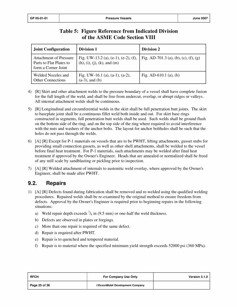
GP 05-01-01 Pressure Vessels June 2007
RFCH For Company Use Only Version 3.1.0
Page 25 of 36 ExxonMobil Development Company
Table 5: Figure Reference from Indicated Division
of the ASME Code Section VIII
Joint Configuration Division 1 Division 2
Attachment of Pressure
Parts to Flat Plates to
form a Corner Joint
Fig. UW-13.2 (a), (e-1), (e-2), (f),
(h), (i), (j), (k), and (m)
Fig. AD-701.3 (a), (b), (c), (f), (g)
Welded Nozzles and
Other Connections
Fig. UW-16.1 (a), (a-1), (a-2),
(a-3), and (b)
Fig. AD-610.1 (a), (b)
4) [R] Skirt and other attachment welds to the pressure boundary of a vessel shall have complete fusion
for the full length of the weld, and shall be free from undercut, overlap, or abrupt ridges or valleys.
All internal attachment welds shall be continuous.
5) [R] Longitudinal and circumferential welds in the skirt shall be full penetration butt joints. The skirt to baseplate joint shall be a continuous fillet weld both inside and out. For skirt base rings
constructed in segments, full penetration butt welds shall be used. Such welds shall be ground flush
on the bottom side of the ring, and on the top side of the ring where required to avoid interference with the nuts and washers of the anchor bolts. The layout for anchor boltholes shall be such that the
holes do not pass through the welds.
6) [A] [R] Except for P-1 materials on vessels that are to be PWHT, lifting attachments, gusset stubs for
providing small connection gussets, as well as other shell attachments, shall be welded to the vessel before final heat treatment. For P-1 materials, such attachments may be welded after final heat
treatment if approved by the Owner's Engineer. Heads that are annealed or normalized shall be freed
of any mill scale by sandblasting or pickling prior to inspection.
7) [A] [R] Welded attachment of internals to austenitic weld overlay, where approved by the Owner's Engineer, shall be made after PWHT.
9.2. Repairs
1) [A] [R] Defects found during fabrication shall be removed and re-welded using the qualified welding
procedures. Repaired welds shall be re-examined by the original method to ensure freedom from
defects. Approval by the Owner's Engineer is required prior to beginning repairs in the following situations:
a) Weld repair depth exceeds 3/8 in (9.5 mm) or one-half the weld thickness.
b) Defects are observed in plates or forgings.
c) More than one repair is required of the same defect.
d) Repair is required after PWHT.
e) Repair is to quenched and tempered material.
f) Repair is to material where the specified minimum yield strength exceeds 52000 psi (360 MPa).

GP 05-01-01 Pressure Vessels June 2007
RFCH For Company Use Only Version 3.1.0
Page 26 of 36 ExxonMobil Development Company
10. Inspection and Testing
1) [I] The term Inspector, as used in this practice, refers to the Owner's Representative.
2) Manufacturer's data reports shall be made available to the Inspector at the time of inspection.
3) [A] Manufacturer's Examination and Testing plan—The Vendor shall submit, for the Purchaser's approval, a detailed plan of applicable examinations and tests required for the individual components
and weldments of each vessel. Specific examinations applicable to linings or claddings shall be
included to the extent of the Vendor's responsibility.
4) [I] Appendix Table A–1 summarizes the minimum examination and testing requirements for pressure vessel components and materials.
10.1. Examination Methods and Acceptance Criteria
1) [R] Spot radiography shall be per the applicable code, except that the acceptance standards shall be
per 100 percent radiography requirements.
2) [R] Radiographic film—Fluorescent intensifying screens such as calcium tungstate shall not be used.
3) [R] Radiographic film length shall be 10 in. (250 mm) minimum, except if the weld is less than 10 in.
long. In such cases, film length shall be the full length of the weld.
4) [A] [R] For vessels made of materials other than carbon steel, the D-C prod method of magnetic particle examination shall be used prior to final PWHT; the A-C yoke or coil method of magnetic
particle examination shall be used after final PWHT. For carbon steel vessels, the A-C yoke method
may be used prior to PWHT, when approved by the Owner's Engineer.
5) [R] Before welding set-on nozzles, the plate below the nozzle weld shall be ultrasonically examined.
Any indications or laminations found within 1/4 x t of the surface of the plate are unacceptable (where
t = plate thickness).
10.2. Weld Quality Control
1) [R] For vessels or sections of vessels where buttwelded seams are 100 percent radiographed or ultrasonically examined, all other pressure containing welds and all attachment welds to pressure
containing parts shall be examined as follows:
a) [A] Pressure containing welds (such as nozzle-to-shell welds and nozzle welds) shall be examined by the ultrasonic method using either the straight beam or shear wave mode. If
ultrasonic examination is not feasible, alternative inspection methods, such as magnetic particle
examination for approximately every 1/4 in. (6 mm) of weld deposit thickness, may be substituted
if approved by the Owner's Engineer.
b) Support skirt welds shall be examined by the ultrasonic method using either the straight beam or
shear wave mode.
c) Lifting lug welds shall be examined by the magnetic particle method.
d) All attachment welds to pressure containing parts on materials other than P1, Groups 1 and 2, shall be examined by the magnetic particle method. If the material is non-magnetic, the liquid penetrant inspection method shall be used in place of the magnetic particle method. Accessible
welds subject to PWHT shall be inspected after PWHT.

GP 05-01-01 Pressure Vessels June 2007
RFCH For Company Use Only Version 3.1.0
Page 27 of 36 ExxonMobil Development Company
e) All locations of temporary attachment welds on materials other than P1, Groups 1 and 2, shall be
inspected according to Item (1d) of this Section.
2) [R] If 100 percent radiography is not specified, spot radiographs shall be made as follows:
a) For cylindrical vessels, one spot shall be examined in each circumferential joint, and in each
longitudinal joint between adjacent circumferential joints, at locations designated by the
Inspector.
b) For spherical vessels, a spot radiograph shall be taken at each weld intersection, and one for each
20 ft (6 m) of weld seam, at locations designated by the Inspector.
c) For spot-radiographed vessels, 20 percent of the nozzle-to-shell welds (2 minimum) shall be PT
examined as follows:
i) The lesser of 12 linear in. (300 mm) or the complete weld length of the backside of the root
area after backgouging or grinding, and
ii) Both sides of the completed weld shall be examined.
If cracks are found, two additional nozzles shall be examined.
3) [A] [R] Where 100 percent radiography is specified, ultrasonic examination in accordance with
ASME 2235 or equivalent procedure in the applicable design code may be used with Owner's
Engineer approval. The qualification test required by ASME 2235 (or equivalent) shall be performed "blind" and witnessed by a third party. Owner's Engineer or Owner's designee shall approve the
results of the qualification test. Other considerations for the qualification shall include:
a) Ultrasonic scan plan shall be submitted and reviewed prior to qualification.
b) Qualification block design: The "qualification block," sometimes referred to as a "mockup," is
not equivalent to a "calibration block" (which typically contains flat bottom or side drilled holes). The qualification block shall be designed to include the defect types anticipated by the welding
process and consider limitations that may be encountered during UT inspection. Weld bevel,
weld process, and weld cap/root geometry shall be representative of field welds, to the extent practical. At least two planar flaws (one OD and one ID) shall be included, representative of
weld defects, and be constructed through controlled welding or EDM (electrical discharge
machining). Wide machined grooves are not acceptable for these two plan flaws. Weld overlay or cladding on block shall also be consistent with field construction. In addition to the minimum
number of qualification defects required by ASME 2235, the inclusion of additional defects
should be considered in the event that some operator training is required.
c) Qualification block procurement and testing: It is Contractor's responsibility to ensure that the qualification block is correctly designed and procured.
d) Owner's Engineer or representative (knowledgeable in UT) shall be present for qualification,
review of qualification results, and review of final scan plan.
e) [A] Acceptable Performance: Performance shall be based on criteria in ASME 2235 (or equivalent). Assessment of qualification results shall consider both detection and overalls (false
positive calls). If initial results from blind qualification are unsatisfactory, retesting may be
allowed by Owner's Engineer. Owner's Engineer (or designee) may provide selective technical training and coaching prior to retesting.
f) Qualification block shall be available at fabrication site for performance check or requalification,
in event of change to scan plan or equipment.
4) [R] Welded joints covered by reinforcing pads shall be 100 percent radiographed prior to installation
of the reinforcing pad.

GP 05-01-01 Pressure Vessels June 2007
RFCH For Company Use Only Version 3.1.0
Page 28 of 36 ExxonMobil Development Company
5) [S] If the stress during hydrotest in any Category A seam (per ASME SEC VIII D1) is not greater
than or equal to that seam's stress under
etemperaturdesignatstressallowable
etemperaturroomatstressallowableconditioncorrodedtheinpressureDesign
then the seam shall be subjected to a 100 percent radiographic inspection, or an ultrasonic
examination.
6) [R] All attachment welds and all areas where fitup bars, etc., were temporarily attached shall be
examined by magnetic particle techniques before final PWHT and after hydrostatic testing, for materials having either (a) or (b) below:
a) A minimum specified tensile strength of 80000 psi (550 MPa) or greater.
b) A P-number other than P-1, P-4x, or P-8.
7) [R] Fillet welds on intermediate heads shall be given a magnetic particle or liquid penetrant
examination after hydrostatic testing.
8) [R] All reinforcing pad welds shall be tested to at least 15 psig (103 kPa) with dry air or nitrogen (after PWHT, if PWHT is required).
9) [R] Vertical vessel support skirts—The finished skirt-to-shell weld shall be examined by the magnetic
particle method after any required PWHT.
10) [R] Nozzle and communicating chamber butt joints exempt from RT inspection according to Par. UW-11 of ASME SEC VIII D1 shall be visually inspected from the ID. Should this prove impossible
or fail to meet the requirements of the Owner's Inspector, these welds shall be RT inspected to the
same level as the vessel girth seams.
10.3. Materials Testing
1) [R] Heat treated plate materials—For all low alloy steels, and carbon steel over 2 in. (50 mm)
thickness, specimens for testing shall be prepared from actual vessel material which has been subjected to an equivalent total thermal treatment as the vessel material in the final fabricated
condition.
2) [*] When specified, specimens shall be subjected to additional thermal treatment cycles equivalent to
those resulting from anticipated shop or field repairs, or field modifications.
3) [S] [R] Charpy impact tests are required for deposited weld metal from electroslag, electrogas, and
other single pass butt welds through the full thickness of the material. Tests shall be made on weld
production impact test plates (run-off tabs). Impact test procedures and values shall meet the requirements in GP 18-10-01.
11. Preparation for Shipment
1) [R] Cleaning and blanking—Vessels shall be free of loose scale, dirt, and foreign material. Liquid
used for testing or cleaning shall be completely drained. Vessel flanged openings shall be blanked
with bolted metal, wood, or plastic covers no smaller than the flange OD. Beveled and threaded ends shall be protected with metal or plastic covers or caps. High alloy vessels shall be blown dry with air,

GP 05-01-01 Pressure Vessels June 2007
RFCH For Company Use Only Version 3.1.0
Page 29 of 36 ExxonMobil Development Company
and all nozzle, manway, vent, and connection openings shall be blanked, plugged, or capped to
prevent the entry of moisture and meet the requirements of GP 18-10-01.
2) [R] Machined or threaded exterior surfaces of carbon steel, and ferrous alloys with a nominal
chemistry of 12Cr and below, shall be protected from corrosion during shipment and subsequent storage by coating with a rust preventive of a type: (1) to provide protection during outdoor storage
for a period of twelve months exposed to a normal industrial environment, and (2) to be removable
with mineral spirits.

GP 05-01-01 Pressure Vessels June 2007
RFCH For Company Use Only Version 3.1.0
Page 30 of 36 ExxonMobil Development Company
Appendix A: Examination and Testing Requirements
Table A–1: Examination and Testing Requirements
Components
and
Materials
Examination
and Testing
Requirements
I. Base Material
A) Plates, shell, and head
B) Nozzles
C) Internals
D) Weld filler metal
II. Welding Qualifications (7)
A) Weld metal
B) Weld metal and heat
affected zone
III. Shell and Head Seams
(Code Category A and B Welds)
IV. Nozzle Welds
Notes:
(1) Extent of requirements for Radiography, Magnetic Particle, Ultrasonics, or Liquid PenetrantExamination shall be as specified in this practice.
(2) Impact Testing shall be according to GP 18-10-01.
(3) Weld filler metal chemical analysis shall be certified by Weld Filler Metal Supplier. Otherweld filler metal testing shall be according to the Standard/Code of Construction.
(4) Abbreviations used are:
T.S.-Tensile StressY.S.-Yield StressEL.-ElongationR.A.-Reduction of Area
(5) Production impact test plates according to Section 10.3, Item 2).
(6) Hardness testing shall be according to GP 18-10-01.
(7) For weld overlay and back cladding, see Appendix B.
X X X X
X X X X
X X X
(3)
(3) (3) (3) X
X X X X
(5) X X X X X
X X X X
GP 05-01-01 Pressure Vessels June 2007
RFCH For Company Use Only Version 3.1.0
Page 31 of 36 ExxonMobil Development Company
Appendix B: Additional Requirements for Clad Vessels
B–1. Integral Bonded Cladding
[*] [R] Cladding thickness shall be not less than 1/8 in. (3.2 mm), unless otherwise specified.
B–2. Connections and Flanges Attached to Integrally Clad or Weld Overlaid Equipment
1) [A] [R] Sleeve lined connections shall not be used unless specifically authorized by the Owner's Engineer. Any request to use sleeve linings shall be accompanied by detailed design information
including the provision for differential thermal expansion, a welding procedure (WPS), and a
fabrication sequence and inspection plan.
2) [R] Connections NPS 2 (50 mm) and smaller shall be one of the following:
a) Weld overlaid or integrally bond clad by explosion welding.
b) Solid alloys, provided the following conditions are met:
i) [A] The mean coefficient of linear thermal expansion of the connection and of the weld metal
used for attachment shall fall within 20 percent of the coefficient of the shell or head
material at the design temperature. Solid connections, where there is more than a 20 percent difference between the coefficient of expansion of the connection and that of the vessel
material, require specific approval by the Owner's Engineer.
ii) [A] A description of the materials, welding procedures and installation details shall be submitted to the Purchaser for Owner's Engineer approval.
iii) Tests shall be performed using materials representative of the nozzle and vessel materials to demonstrate satisfactory weldability.
iv) All ASME P-No. 7 materials (i.e., Type 405 or 410S) shall be postweld heat treated (PWHT).
3) [R] Connections over NPS 2 (50 mm) shall be one of the following:
a) Weld overlaid.
b) Integrally clad by explosion welding.
c) Produced from roll-bonded integrally clad plate by forming into a cylinder and welding.
4) [R] Flange faces of weld overlaid and integrally clad connections shall be weld overlaid and finish
machined in the gasket area, with a minimum 1/8 in. (3.2 mm) overlay or cladding thickness after
machining.
5) [R] Materials used for weld overlay or integral cladding of connections and flanges shall be the same type and thickness as required for cladding the vessel or head to which they are attached.
GP 05-01-01 Pressure Vessels June 2007
RFCH For Company Use Only Version 3.1.0
Page 32 of 36 ExxonMobil Development Company
B–3. Inspection and Testing of Integral Bonded Cladding
1) [R] Shear strength tests are required on all integrally clad steel plate in accordance with the provisions
of the applicable materials specification.
2) [R] Prior to fabrication, integrally clad material shall be subject to ultrasonic examination from the
clad surface as follows:
a) Procedures and records shall be in accordance with ASME SEC II A SA-578/SA-578M
Paragraphs 5 and 6 with the following exception: all indications with amplitudes equal to or greater than 50 percent of the initial back reflection and accompanied by a 50 percent loss of back
reflection shall be recorded, regardless of plate thickness.
b) Acceptance standards shall be ASME SEC II A SA-578/SA-578M, Level A for the backing steel,
and Supplementary Level S6 for the cladding bond. For vessels being designed to GP 05-01-02,
Level B should be used as well as Supplementary Level S6 for the cladding bond.
c) Repair or replacement of the clad product shall be as per agreement between the Vendor and the
Owner's Engineer.
3) [R] Subsequent to final PWHT, integrally clad vessels and components shall be ultrasonically re-
examined in all locations where the tests conducted (per Item (2) above) required recording of
indications. Acceptance standards shall be in accordance with ASME SEC II A SA-578/SA-578M, Level A for the backing steel, and Supplementary Level S6 for the cladding bond. Defective areas
shall be repaired and re-examined.
4) [R] For hydrogen service, integrally clad components shall be ultrasonically examined per Items (2)
and (3), above , with the following additional requirements:
a) Prior to fabrication, materials shall be scanned along perpendicular grid lines on nominal 6 in.
(150 mm) centers and shall cover a path approximately 3 in. (75 mm) wide.
b) [*] When specified, vessels and components shall be scanned along perpendicular grid lines on
12 in. (300 mm) centers after final PWHT.
5) [R] Integrally clad surfaces to which minor load bearing attachments are to be welded, and also
locations designated for "future attachments," shall be 100 percent ultrasonically examined from the clad side. Clad areas within 4 in. (100 mm) of attachment welds shall be included. Acceptance
standards shall be per ASME SEC II A SA-578/SA-578M, Level A for the backing steel and Supplementary Level S7 for the cladding bond.
Any indication of lack of bonding between cladding and base metal shall be cause for rejection.
Defective areas shall be repaired and re-examined.
6) [R] Welding of major load-bearing attachments (maximum tensile stress at the attachment weld is greater than 5 ksi) to the clad side of integrally clad components requires removal of the cladding
prior to making the attachment weld(s). Attachment welds shall be weld overlaid to match the
composition of the adjacent integral cladding.
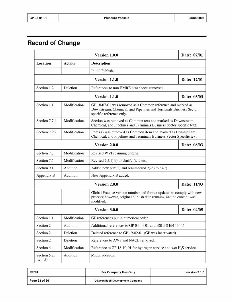
GP 05-01-01 Pressure Vessels June 2007
RFCH For Company Use Only Version 3.1.0
Page 33 of 36 ExxonMobil Development Company
Record of Change
Version 1.0.0 Date: 07/01
Location Action Description
Initial Publish.
Version 1.1.0 Date: 12/01
Section 1.2 Deletion References to non-EMRE data sheets removed.
Version 1.1.0 Date: 03/03
Section 1.1 Modification GP 18-07-01 was removed as a Common reference and marked as
Downstream, Chemical, and Pipelines and Terminals Business Sector
specific reference only.
Section 7.7.4 Modification Section was removed as Common text and marked as Downstream,
Chemical, and Pipelines and Terminals Business Sector specific text.
Section 7.9.2 Modification Item (4) was removed as Common item and marked as Downstream,
Chemical, and Pipelines and Terminals Business Sector Specific text.
Version 2.0.0 Date: 08/03
Section 7.3 Modification Revised WVI scanning criteria.
Section 7.5 Modification Revised 7.5.1) b) to clarify field test.
Section 9.1 Addition Added new para 2) and renumbered 2)-6) to 3)-7).
Appendix B Addition New Appendix B added.
Version 2.0.0 Date: 11/03
Global Practice version number and format updated to comply with new process; however, original publish date remains, and no content was
modified.
Version 3.0.0 Date: 04/05
Section 1.1 Modification GP references put in numerical order.
Section 2 Addition Additional references to GP 04-14-01 and BSI BS EN 13445.
Section 2 Deletion Deleted reference to GP 19-02-01 (GP was inactivated).
Section 2 Deletion References to AWS and NACE removed.
Section 4 Modification Reference to GP 18-10-01 for hydrogen service and wet H2S service.
Section 5.2, Item 5)
Addition Minor addition.

GP 05-01-01 Pressure Vessels June 2007
RFCH For Company Use Only Version 3.1.0
Page 34 of 36 ExxonMobil Development Company
Section 6 Addition Minor additions.
Section 7.7.3 Addition Nozzle reinforcement in HF service.
Section 7.8 Modification Vents.
Section 7.9.1 Modification Horizontal vessel saddles.
Section 7.9.2 Modification Vessel support lugs.
Section 7.9.3,
Item 4e)
Addition Bolted-on tailing frames.
Section 9.7 Modification Cold formed heads.
Section 10.2,
Item 3)
Addition UT qualification blocks.
Appendix B–2,
Item 1)
Modification Thermal expansion.
Version 3.1.0 Date: 06/07
Section 6. Item
(1)
Modification Wording was modified.
Section 7.7.1,
Item (3)
Modification NPS 2 minimum flange size
Section 7.7.1,
Item (8b)
Modification Split rationale paragraph for clarity
Section 7.7.2 Addition Plugs and caps for vent and drain connections
Section 7.7.5,
Item (2)
Modification Link update
Section 7.8,
Item (1)
Modification Rewording of paragraph and rationale statement
Section 8, Item
(2d)
Addition Rigidity Index, J
Appendix B-3,
Item (2b) and
(5)
Modification Level 1 to Level A
All Global
Practices
Modifications To standardize the format of the Global Practices and to meet other
requirements, the following changes have been implemented:
"For ExxonMobil Use Only" has been replaced with "For Company Use
Only."
A copyright waiver has been added in the first page Footer.
The definition of asterisks in the Scope has been deleted. The asterisk is
now defined in the Purpose Code attachment and is used within brackets
as other Purpose Codes.
GP 05-01-01 Pressure Vessels June 2007
RFCH For Company Use Only Version 3.1.0
Page 35 of 36 ExxonMobil Development Company
Multiple paragraphs within a Section have been numbered.
The standard text for Required References has been modified.
The standard text for Additional Requirements has been modified.
The [S] Purpose Code has been modified.
The following Purpose Codes have been added:
[*] for additional information or decision required of Owner's Engineer.
[A] for approval requirements before beginning work or finalizing
design.

GP 05-01-01 Pressure Vessels June 2007
RFCH For Company Use Only Version 3.1.0
Page 36 of 36 ExxonMobil Development Company
Attachment: Purpose Code Definitions
Code Description
* Assigned to paragraphs that require the Owner's Engineer to provide additional information or
make a decision.
A Assigned to paragraphs that require approval from the Owner's Engineer before the work may
proceed or the design is finalized.
C Assigned to paragraphs whose primary purpose is reduced costs. Reduced cost in this context
refers to initial investment cost and does not include life cycle cost considerations. Life cycle
cost considerations are captured under reliability, maintainability, or operability purpose codes.
E Assigned to paragraphs whose primary purpose is driven by environmental considerations. Environmental considerations typically include specifications intended to protect against
emissions/leakage to the air, water, and/or soil. Deviations from the specifications contained
in such paragraphs require formal review and approval according to local environmental policy.
I Assigned to paragraphs that provide only clarifying information, such as Scope statements,
definitions of terms, etc.
M Assigned to paragraphs whose primary purpose is to provide for maintainability of equipment or systems. Maintainability provisions are those that facilitate the performance of maintenance
on equipment/systems either during downtimes or during onstream operations.
O Assigned to paragraphs whose primary purpose is to assure operability of equipment or
systems. Operability is the ability of the equipment/system to perform satisfactorily even though conditions are off-design, such as during start-ups, process swings, subcomponent
malfunction, etc.
R Assigned to paragraphs whose primary purpose is to improve or assure the reliability of
equipment or systems. Reliability is a measure of the ability of equipment/systems to operate without malfunction or failure between planned maintenance interventions.
S Assigned to paragraphs containing specifications/guidance where the primary purpose is the
avoidance of incidents impacting personnel safety, operational safety, and the public in general and/or involving responses to emergency situations. Any deviation from the specifications
contained in such designated paragraphs requires formal review and approval according to
local safety policy.
Personnel Safety: Refers to incident-related personnel injuries or illness, e.g., burns, cuts, abrasions, inhalation of or exposure to dangerous substances, etc., that
could result in medical treatment, restricted work, lost-time incidents, or
fatalities.
Operational
Safety:
Refers to the prevention and control of process releases, fires, and/or
explosions that could result in damage to equipment, process disruption,
or personnel injury or illness.

GP 05-03-01 Pressure Testing of Unfired Pressure Vessels March 2005
Refining/Chemicals, Downstream Imperial Oil
For ExxonMobil Use Only Version 1.2.0
Page 1 of 7 ExxonMobil Development Company
Pressure Testing of Unfired Pressure Vessels
GP 05-03-01
Scope
1) [I] This Global Practice (GP) covers the pressure testing of pressure vessels, including TEMA type, double pipe, and air-cooled heat exchangers.
2) [I] An asterisk (*) indicates that a decision by the purchaser is required or that additional information
is furnished by the purchaser.
GP 05-03-01 Pressure Testing of Unfired Pressure Vessels March 2005
RFCH, DIOL For ExxonMobil Use Only Version 1.2.0
Page 2 of 7 ExxonMobil Development Company
Table of Contents
1. Required References ............................................................................................ 3
1.1. Global Practices-ExxonMobil Engineering Practices .................................... 3
1.2. ASME-American Society of Mechanical Engineers ...................................... 3
2. Definitions.............................................................................................................. 3
3. Test Procedures .................................................................................................... 3
3.1. Pressure Levels............................................................................................ 4
3.2. Duration........................................................................................................ 4
3.3. Temperature Requirements.......................................................................... 4
Record of Change ......................................................................................................... 6
Attachment: Purpose Codes Definitions.................................................................... 7
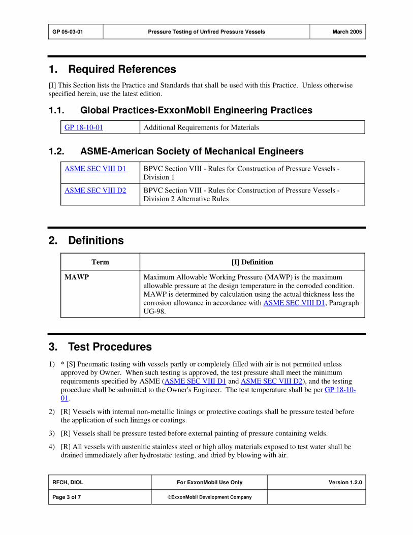
GP 05-03-01 Pressure Testing of Unfired Pressure Vessels March 2005
RFCH, DIOL For ExxonMobil Use Only Version 1.2.0
Page 3 of 7 ExxonMobil Development Company
1. Required References
[I] This Section lists the Practice and Standards that shall be used with this Practice. Unless otherwise specified herein, use the latest edition.
1.1. Global Practices-ExxonMobil Engineering Practices
GP 18-10-01 Additional Requirements for Materials
1.2. ASME-American Society of Mechanical Engineers
ASME SEC VIII D1 BPVC Section VIII - Rules for Construction of Pressure Vessels -
Division 1
ASME SEC VIII D2 BPVC Section VIII - Rules for Construction of Pressure Vessels - Division 2 Alternative Rules
2. Definitions
Term [I] Definition
MAWP Maximum Allowable Working Pressure (MAWP) is the maximum
allowable pressure at the design temperature in the corroded condition. MAWP is determined by calculation using the actual thickness less the
corrosion allowance in accordance with ASME SEC VIII D1, Paragraph
UG-98.
3. Test Procedures
1) * [S] Pneumatic testing with vessels partly or completely filled with air is not permitted unless approved by Owner. When such testing is approved, the test pressure shall meet the minimum
requirements specified by ASME (ASME SEC VIII D1 and ASME SEC VIII D2), and the testing
procedure shall be submitted to the Owner's Engineer. The test temperature shall be per GP 18-10-01.
2) [R] Vessels with internal non-metallic linings or protective coatings shall be pressure tested before the application of such linings or coatings.
3) [R] Vessels shall be pressure tested before external painting of pressure containing welds.
4) [R] All vessels with austenitic stainless steel or high alloy materials exposed to test water shall be drained immediately after hydrostatic testing, and dried by blowing with air.
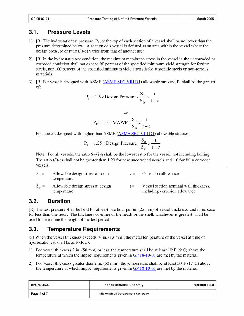
GP 05-03-01 Pressure Testing of Unfired Pressure Vessels March 2005
RFCH, DIOL For ExxonMobil Use Only Version 1.2.0
Page 4 of 7 ExxonMobil Development Company
3.1. Pressure Levels
1) [R] The hydrostatic test pressure, PT, at the top of each section of a vessel shall be no lower than the pressure determined below. A section of a vessel is defined as an area within the vessel where the
design pressure or ratio t/(t-c) varies from that of another area.
2) [R] In the hydrostatic test condition, the maximum membrane stress in the vessel in the uncorroded or
corroded condition shall not exceed 90 percent of the specified minimum yield strength for ferritic steels, nor 100 percent of the specified minimum yield strength for austenitic steels or non-ferrous
materials.
3) [R] For vessels designed with ASME (ASME SEC VIII D1) allowable stresses, PT shall be the greater
of:
ct
t
S
SPressureDesign5.1P
dt
rt
T
or
ct
t
S
SMAWP3.1P
dt
rt
T
For vessels designed with higher than ASME (ASME SEC VIII D1) allowable stresses:
ct
t
S
SPressureDesign25.1P
dt
rt
T
Note: For all vessels, the ratio Srt/Sdt shall be the lowest ratio for the vessel, not including bolting.
The ratio t/(t-c) shall not be greater than 1.20 for new uncorroded vessels and 1.0 for fully corroded
vessels.
Srt = Allowable design stress at room temperature
c = Corrosion allowance
Sdt
= Allowable design stress at design
temperature
t = Vessel section nominal wall thickness,
including corrosion allowance
3.2. Duration
[R] The test pressure shall be held for at least one hour per in. (25 mm) of vessel thickness, and in no case for less than one hour. The thickness of either of the heads or the shell, whichever is greatest, shall be
used to determine the length of the test period.
3.3. Temperature Requirements
[S] When the vessel thickness exceeds 1/2 in. (13 mm), the metal temperature of the vessel at time of
hydrostatic test shall be as follows:
1) For vessel thickness 2 in. (50 mm) or less, the temperature shall be at least 10 F (6 C) above the
temperature at which the impact requirements given in GP 18-10-01 are met by the material.
2) For vessel thickness greater than 2 in. (50 mm), the temperature shall be at least 30 F (17 C) above
the temperature at which impact requirements given in GP 18-10-01 are met by the material.
GP 05-03-01 Pressure Testing of Unfired Pressure Vessels March 2005
RFCH, DIOL For ExxonMobil Use Only Version 1.2.0
Page 5 of 7 ExxonMobil Development Company
3) When the required vessel temperature during hydrostatic test is greater than 70 F (21 C), this temperature shall be marked on the vessel nameplate.
GP 05-03-01 Pressure Testing of Unfired Pressure Vessels March 2005
RFCH, DIOL For ExxonMobil Use Only Version 1.2.0
Page 6 of 7 ExxonMobil Development Company
Record of Change
Version 1.0.0 Date: 07/01
Location Action Description
Initial Publish.
Version 1.1.0 Date: 02/02
Section 3.1 Addition Added Purpose Code [R] to item 3).
Version 1.1.0 Date: 09/03
Global Practice version number and format updated to comply with new
process; however, original publish date remains, and no content was
modified.
Version 1.2.0 Date: 03/05
Section 3.1,
Item (3) Note
Modification Stress ratio not to include bolting; thickness ratio for corroded and
uncorroded vessel specified.

GP 05-03-01 Pressure Testing of Unfired Pressure Vessels March 2005
RFCH, DIOL For ExxonMobil Use Only Version 1.2.0
Page 7 of 7 ExxonMobil Development Company
Attachment: Purpose Codes Definitions
Code Description
C Assigned to paragraphs containing specifications whose primary purpose is reduced costs.
Reduced cost in this context refers to initial investment cost and does not include Life-Cycle
cost considerations. Life-Cycle cost considerations are captured under reliability,
maintainability, or operability purpose codes.
E Assigned to paragraphs containing specifications whose primary purpose is driven by
environmental considerations. Environmental considerations typically include specifications
intended to protect against emissions/leakage to the air, water, and/or soil. Deviations from the specifications contained in such paragraphs require formal review and approval according to
local environmental policy.
I Assigned to paragraphs that provide only clarifying information such as Scope statements,
definitions of terms, etc.
M Assigned to paragraphs containing specifications whose primary purpose is to provide for
maintainability of equipment or systems. Maintainability provisions are those that facilitate the
performance of maintenance on equipment/systems either during downtimes or during on-
stream operations.
O Assigned to paragraphs containing specifications whose primary purpose is to assure
operability of equipment or systems. Operability is the ability of the equipment/system to
perform satisfactorily even though conditions are off-design, such as during startups, process swings, subcomponent malfunction, etc.
R Assigned to paragraphs containing specifications whose primary purpose is to improve or
assure the reliability of equipment or systems. Reliability is a measure of the ability of
equipment/systems to operate without malfunction or failure between planned maintenance interventions.
S Assigned to paragraphs containing specifications whose primary purpose is avoidance of
personnel or operational safety incidents. Any deviation from the specifications contained in
such designated paragraphs requires formal review and approval according to local safety policy.
Personnel Safety: Refers to the avoidance of recordable personnel injuries; i.e., burns, cuts,
abrasions, inhalation, or exposure to dangerous substances, etc., that could result in medical treatment, restricted work, lost-time incidents, or
fatalities.
Operational
Safety:
Refers to the prevention and control of process releases, fires, explosions,
etc.

GP 15-02-01 Temperature Instruments October 2008
Refining/Chemicals, Downstream Imperial Oil
For Company Use Only Version 2.1.0
Page 1 of 15 ExxonMobil Development Company
Copyright Waiver ExxonMobil Development Company and ExxonMobil Pipeline Company hereby license the use of ExxonMobil Engineering Practices System (EMEPS) Global Practices (GPs) for use by any ExxonMobil division, subsidiary, or more-than-50%-owned affiliate. The GPs may be downloaded and modified as necessary for project and affiliate use. Written permission from ExxonMobil Development Company or ExxonMobil Pipeline Company is not required. However, any modified GPs must be renumbered to a project-specific or affiliate-specific number to distinguish them from the GPs on the EMEPS web site. ExxonMobil operated joint ventures may utilize GPs to create project-specific or location-specific specifications. It is the responsibility of individual affiliate or joint venture to ensure that the use of GPs and their derivatives is limited to joint venture related business and not disclosed or used outside the JV without appropriate EM management approval.
Temperature Instruments
GP 15-02-01
Scope
1) [I] This Global Practice (GP) covers the design and selection of temperature instruments and sensors.
2) [I] Additional temperature measurement requirements for specific process and equipment items, such
as rotating equipment, fired heaters, motors, and storage tanks, may also be covered by the equipment-specific Practices.
GP 15-02-01 Temperature Instruments October 2008
RFCH, DIOL For Company Use Only Version 2.1.0
Page 2 of 15 ExxonMobil Development Company
Table of Contents
1. Required References ............................................................................................ 3
1.1. Global Practices–ExxonMobil Engineering Practices ................................... 3
1.2. API–American Petroleum Institute................................................................ 3
1.3. ASME–American Society of Mechanical Engineers ..................................... 3
1.4. ASTM–American Society for Testing and Materials ..................................... 3
2. Additional Requirements...................................................................................... 4
2.1. Global Practices–ExxonMobil Engineering Practices ................................... 4
2.2. API–American Petroleum Institute................................................................ 4
2.3. ASTM–American Society for Testing and Materials ..................................... 4
2.4. IEC–International Electrotechnical Commission........................................... 4
2.5. NEMA–National Electrical Manufacturers Association ................................. 4
3. Basic Design.......................................................................................................... 5
4. Thermocouples ..................................................................................................... 5
5. Resistance Temperature Devices ........................................................................ 8
6. Other Temperature Measuring Elements ............................................................ 9
7. Transmitters .......................................................................................................... 9
8. Temperature-Indicating Gauges .......................................................................... 9
9. Thermowells ........................................................................................................ 10
10. Inspection and Testing ....................................................................................... 12
Record of Change ....................................................................................................... 13
Attachment: Purpose Code Definitions.................................................................... 15
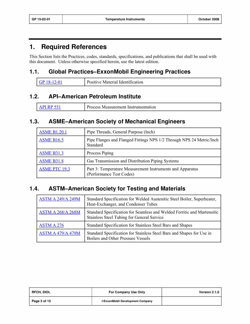
GP 15-02-01 Temperature Instruments October 2008
RFCH, DIOL For Company Use Only Version 2.1.0
Page 3 of 15 ExxonMobil Development Company
1. Required References
This Section lists the Practices, codes, standards, specifications, and publications that shall be used with this document. Unless otherwise specified herein, use the latest edition.
1.1. Global Practices–ExxonMobil Engineering Practices
GP 18-12-01 Positive Material Identification
1.2. API–American Petroleum Institute
API RP 551 Process Measurement Instrumentation
1.3. ASME–American Society of Mechanical Engineers
ASME B1.20.1 Pipe Threads, General Purpose (Inch)
ASME B16.5 Pipe Flanges and Flanged Fittings NPS 1/2 Through NPS 24 Metric/Inch Standard
ASME B31.3 Process Piping
ASME B31.8 Gas Transmission and Distribution Piping Systems
ASME PTC 19.3 Part 3: Temperature Measurement Instruments and Apparatus
(Performance Test Codes)
1.4. ASTM–American Society for Testing and Materials
ASTM A 249/A 249M Standard Specification for Welded Austenitic Steel Boiler, Superheater,
Heat-Exchanger, and Condenser Tubes
ASTM A 268/A 268M Standard Specification for Seamless and Welded Ferritic and Martensitic
Stainless Steel Tubing for General Service
ASTM A 276 Standard Specification for Stainless Steel Bars and Shapes
ASTM A 479/A 479M Standard Specification for Stainless Steel Bars and Shapes for Use in
Boilers and Other Pressure Vessels

GP 15-02-01 Temperature Instruments October 2008
RFCH, DIOL For Company Use Only Version 2.1.0
Page 4 of 15 ExxonMobil Development Company
2. Additional Requirements
[*] This Section lists the additional Practices, codes, standards, specifications, and publications that shall be used with this document only where specified. Unless otherwise specified herein, use the latest
edition.
2.1. Global Practices–ExxonMobil Engineering Practices
GP 15-07-02 Protective Systems
2.2. API–American Petroleum Institute
API MPMS 7 Manual of Petroleum Measurement Standards - Chapter 7: Temperature
Determination
2.3. ASTM–American Society for Testing and Materials
ASTM E 230 Standard Specification and Temperature-Electromotive Force (EMF)
Tables for Standardized Thermocouples
ASTM E 235 Standard Specification for Thermocouples, Sheathed, Type K and Type
N, for Nuclear or for Other High-Reliability Applications
ASTM E 1137/E
1137M Standard Specification for Industrial Platinum Resistance Thermometers
2.4. IEC–International Electrotechnical Commission
IEC 60529 Degrees of Protection Provided by Enclosures (IP Code)
IEC 60751 Industrial Platinum Resistance Thermometer Sensors
2.5. NEMA–National Electrical Manufacturers Association
NEMA 250 Enclosures for Electrical Equipment (1000 Volts Maximum)

GP 15-02-01 Temperature Instruments October 2008
RFCH, DIOL For Company Use Only Version 2.1.0
Page 5 of 15 ExxonMobil Development Company
3. Basic Design
1) [S] [M] Thermowells are required for all temperature measuring devices used in flammable, toxic, or otherwise hazardous pressurized or vacuum systems. Thermowells are not required for temperature
measurement of equipment, such as reactor shell skin, machinery bearings, or motor windings, where
there is no risk to personnel from the process fluid during removal of the measuring element, or
where radial thermocouples are used. Where a thermowell is not used, a permanent label shall be affixed to the primary element, indicating that there is no thermowell.
2) [O] Tip-sensitive elements shall be provided with a mechanical means of ensuring a solid thermal
connection with the thermowell tip (spring loaded, compression fitting, etc.).
3) [A] [C] [O] For general temperature measurement and control, thermocouples shall be the preferred choice for the primary sensing elements. Alternatively, resistance temperature devices (RTDs) may
be used, subject to approval by the Owner's Engineer. The choice would be based on temperature
range span and/or accuracy.
4) [O] [R] Where specified by the Owner's Engineer, critical temperature control loops that use a thermocouple for the sensing element may be furnished with a second thermocouple as a check
sensor. A comparison of measured values can be used as a diagnostic tool to determine possible drift
and/or abnormal operations (e.g., start-up, shutdowns, etc.).
5) Use of a dual thermocouple in a single thermowell is the preferred method of supplying the check
measurement. However, where issues such as intrinsic safety exist, the check thermocouple shall be
installed in a separate thermowell within 18 in. (0.46 m) of the control thermocouple. Current applied
technology (sheathing and transmitters) essentially eliminates the need for separate thermowells.
6) [O] [R] Temperature control loops and other critical loops (Safety Instrument Systems [SIS], etc.) shall use a field-mounted transmitter.
7) [R] A single thermocouple shall not be connected to more than one device. A single thermocouple
signal needed at more than one receiver device shall first be converted to a standard current or voltage
signal.
8) [A] [M] [R] The use of filled-system or bi-metallic temperature switches requires approval by the Owner's Engineer. Temperature switches shall be snap-acting type. Other temperature measuring
elements may be used subject to approval by the Owner's Engineer.
9) [A] [O] [R] Thermocouple/thermowell installations, especially where the measured temperature is
higher than 212 F (100 C), shall be designed to reduce the probability for water (condensation or
rain) accumulation in the tip of the thermowell. Considerations shall include keeping the tip of the thermowell at or above the horizontal and providing a drain path for condensed water. Designs
require approval by the Owner's Engineer.
4. Thermocouples
1) [R] Thermocouples for general service shall be mineral-insulated, metal-sheathed with the following
construction:

GP 15-02-01 Temperature Instruments October 2008
RFCH, DIOL For Company Use Only Version 2.1.0
Page 6 of 15 ExxonMobil Development Company
a) Minimum wire size shall be 20 AWG (0.5 mm2).
b) [*] Choice of grounded or ungrounded thermocouple hot junction shall be specified by the
Owner's Engineer.
c) Sheath shall be 1/4 in. (6 mm) OD, Type 316 stainless steel.
2) [M] Thermocouple head (or conduit fitting) shall be as follows:
a) Enclosure shall be weatherproof to NEMA Type 4 or IP 65 construction and shall meet the
electrical area classification.
b) Body and cover material shall be cast iron or aluminum.
c) Cover shall be threaded and gasketed, with retaining chain attached to body.
d) [A] Flexible connection from thermocouple head to fixed wiring system shall be liquid-tight,
PVC-jacketed steel conduit or armored flexible cable. These are as shown in Figure 31 "Thermocouple-to-Conduit Connections," of API RP 551, Section 5. Other types of construction
may be used, subject to approval.
3) [A] [O] [R] For the temperature range 0 F to +2000 F ( 20 C to +1090 C), the preferred
thermocouple material is chromel-alumel (Type K, per API RP 551), unless other types of material (such as Type J) are required to connect to existing equipment. Thermocouple extension wire
connected to Type K thermocouples shall be Type KX. Use of any other type of thermocouple or
extension wire material requires approval by the Owner's Engineer.
4) [A] [O] For the temperature range 300 F to +200 F ( 195 C to +95 C), the preferred thermocouple
material is copper-constantan (Type T). Thermocouple extension wire connected to Type T
thermocouples shall be Type TX. Use of Type T thermocouples requires approval by the Owner's
Engineer.
5) [A] [I] [R] Tube metal thermocouples (TMT) for fired heaters and boilers shall be "V-Pad" fan type,
grounded thermocouples in accordance with key elements of Figure 1. Key elements of material selection, installation, and dimensions are shown as "typical" and reflect a historical successful
installation. Alternate Vendor recommendations may be considered with the Owner's Engineer
approval. The following requirements shall apply to any installation:
a) Thermocouple material shall be Type K.
b) Tube metal thermocouple sheath material shall be Hastelloy X as indicated in Table 1.
c) A retaining clip and expansion loop shall be provided to allow for movement of tubes and walls
when hot without putting strain on the thermocouple hot junction weld.
d) Material selection and installation and/or welding procedures shall be in accordance with Figure 1
and Vendor requirements and must be proven suitable for the environment.
e) Sheath material and minimum bend radius shall be selected to avoid stress failure due to
movement, sheath diameter, bending stress, temperature, and composition of the combustion
products (e.g., heavy metals and sulfur content in fuel oil).
f) TMT installation/welding procedures shall be in accordance with Figure 1. These procedures
take precedence over any specific Vendor requirements.
g) Terminal heads shall project at least 6 in. (150 mm) from heater or boiler furnace walls.
6) [A] The design and installation of tube metal thermocouples or the proposed use of any alternative design shall require approval by the Owner's Engineer.
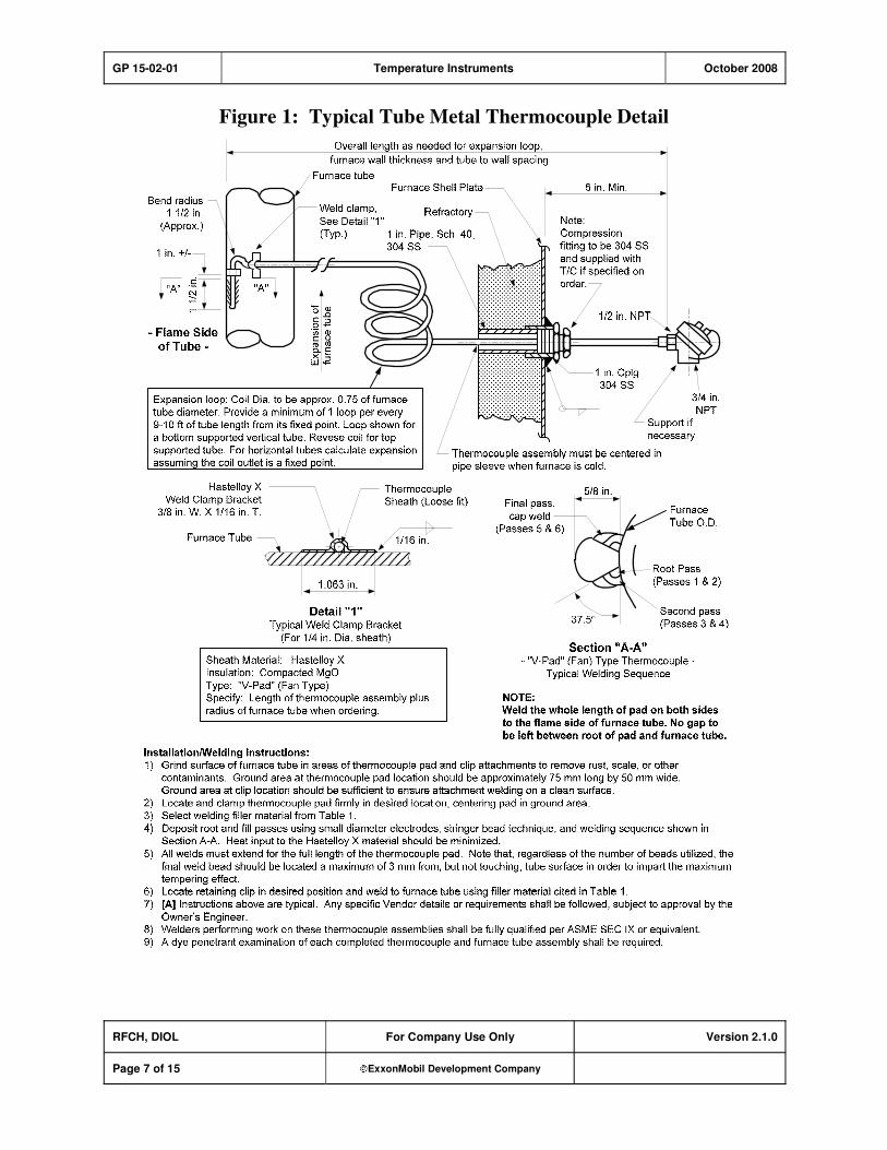
GP 15-02-01 Temperature Instruments October 2008
RFCH, DIOL For Company Use Only Version 2.1.0
Page 7 of 15 ExxonMobil Development Company
Figure 1: Typical Tube Metal Thermocouple Detail
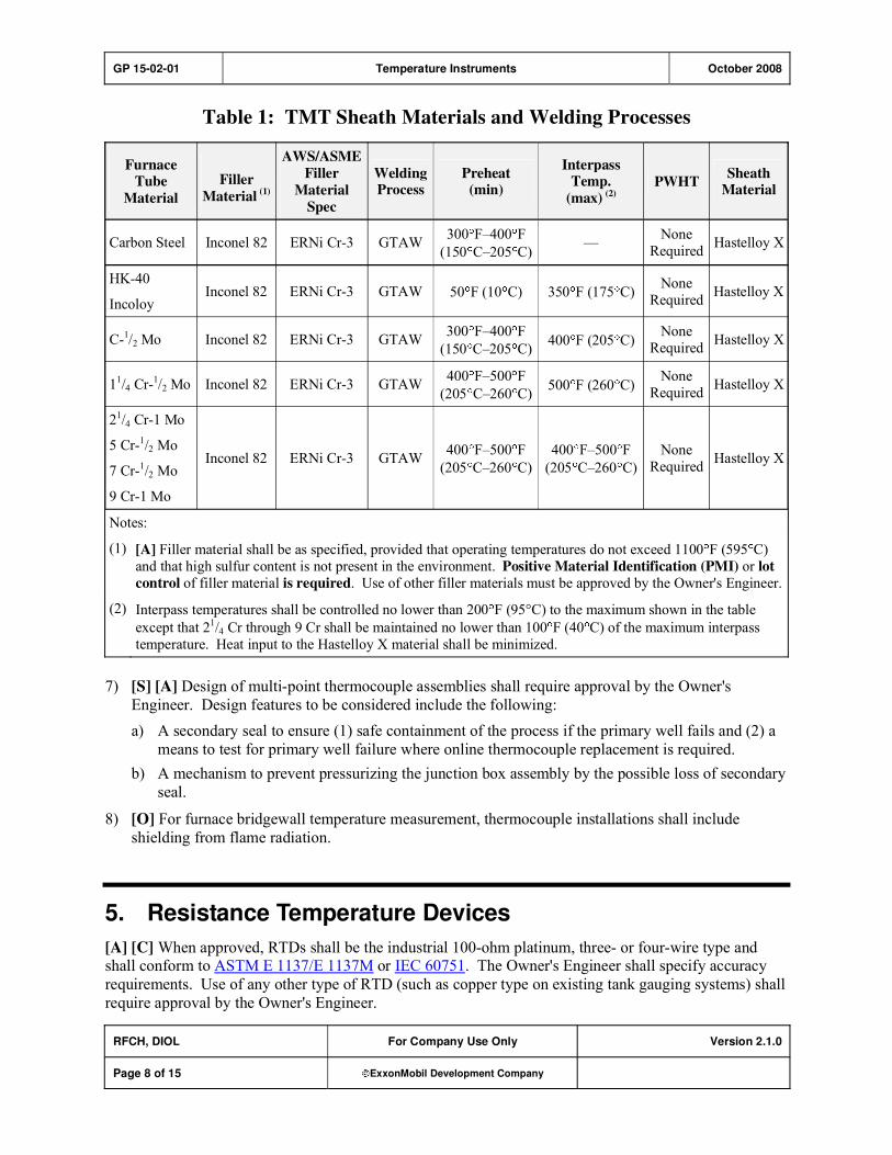
GP 15-02-01 Temperature Instruments October 2008
RFCH, DIOL For Company Use Only Version 2.1.0
Page 8 of 15 ExxonMobil Development Company
Table 1: TMT Sheath Materials and Welding Processes
FurnaceTube
Material
Filler
Material (1)
AWS/ASME
Filler
Material
Spec
Welding Process
Preheat(min)
Interpass Temp.
(max) (2)PWHT
SheathMaterial
Carbon Steel Inconel 82 ERNi Cr-3 GTAW 300 F�400 F
(150 C�205 C)�
None
Required Hastelloy X
HK-40
Incoloy Inconel 82 ERNi Cr-3 GTAW 50 F (10 C) 350 F (175 C)
None
Required Hastelloy X
C-1/2 Mo Inconel 82 ERNi Cr-3 GTAW 300 F�400 F
(150 C�205 C)400 F (205 C)
None
Required Hastelloy X
11/4 Cr-1/2 Mo Inconel 82 ERNi Cr-3 GTAW 400 F�500 F
(205 C�260 C)500 F (260 C)
None
Required Hastelloy X
21/4 Cr-1 Mo
5 Cr-1/2 Mo
7 Cr-1/2 Mo
9 Cr-1 Mo
Inconel 82 ERNi Cr-3 GTAW 400 F�500 F
(205 C�260 C)
400 F�500 F
(205 C�260 C)
None
Required Hastelloy X
Notes:
(1) [A] Filler material shall be as specified, provided that operating temperatures do not exceed 1100 F (595 C)
and that high sulfur content is not present in the environment. Positive Material Identification (PMI) or lot
control of filler material is required. Use of other filler materials must be approved by the Owner's Engineer.
(2) Interpass temperatures shall be controlled no lower than 200 F (95°C) to the maximum shown in the table
except that 21/4 Cr through 9 Cr shall be maintained no lower than 100 F (40 C) of the maximum interpass
temperature. Heat input to the Hastelloy X material shall be minimized.
7) [S] [A] Design of multi-point thermocouple assemblies shall require approval by the Owner's
Engineer. Design features to be considered include the following:
a) A secondary seal to ensure (1) safe containment of the process if the primary well fails and (2) a
means to test for primary well failure where online thermocouple replacement is required.
b) A mechanism to prevent pressurizing the junction box assembly by the possible loss of secondary
seal.
8) [O] For furnace bridgewall temperature measurement, thermocouple installations shall include
shielding from flame radiation.
5. Resistance Temperature Devices
[A] [C] When approved, RTDs shall be the industrial 100-ohm platinum, three- or four-wire type and shall conform to ASTM E 1137/E 1137M or IEC 60751. The Owner's Engineer shall specify accuracy
requirements. Use of any other type of RTD (such as copper type on existing tank gauging systems) shall
require approval by the Owner's Engineer.

GP 15-02-01 Temperature Instruments October 2008
RFCH, DIOL For Company Use Only Version 2.1.0
Page 9 of 15 ExxonMobil Development Company
6. Other Temperature Measuring Elements
[C] When approved, filled-system type primary elements shall meet the following requirements:
1) [A] Maximum bulb temperature shall not exceed 600 F (315 C) unless approved by the Owner's Engineer.
2) The filled-system thermal element bulb and capillary tube shall be all-welded stainless steel. The
capillary shall be protected from mechanical damage by stainless steel spiral-wound armor and
supports. The maximum distance between supports shall be 18 in. (45 cm).
3) Capillary length shall not exceed 10 ft (3 m).
4) A minimum of 50 percent over-range protection shall be provided for all filled-system devices.
5) Compensation for variations in ambient temperature and barometric pressure shall be provided.
6) Filled-system temperature elements installed in thermowells shall be specified and supplied as
complete assemblies.
7. Transmitters
1) [O] Transmitters shall have the narrowest available span that covers the anticipated temperatures during start-up, normal operations, and process upset conditions. Where possible, the range shall be
selected so that normal temperature will be in the middle third of the range.
2) [S] Transmitters shall have a selectable upscale or downscale burnout (open circuit) feature without
transient spikes on burnout.
3) [*] For protective systems, sensing element open circuit protection shall be in accordance with GP 15-07-02. For nonprotective control functions, sensing element open circuit protection shall operate
to drive the controller output to the final control element failure position. The Owner's Engineer shall
specify the direction of open circuit detection in all other applications.
8. Temperature-Indicating Gauges
[O] Local temperature-indicating gauges shall be adjustable-angle, bi-metallic or filled-system
thermometers with rigid stems.
1) Minimum dial size shall be 4 in. (10 cm).
2) Minimum stem length shall be 9 in. (22 cm).
3) [*] Weatherproof cases shall be used unless otherwise specified.
4) Dial thermometers installed in thermowells shall be specified and supplied as complete assemblies.
5) If necessary for readability or in vibrating services, a dial thermometer with capillary shall be used.
Vapor-filled capillary systems shall not be used.
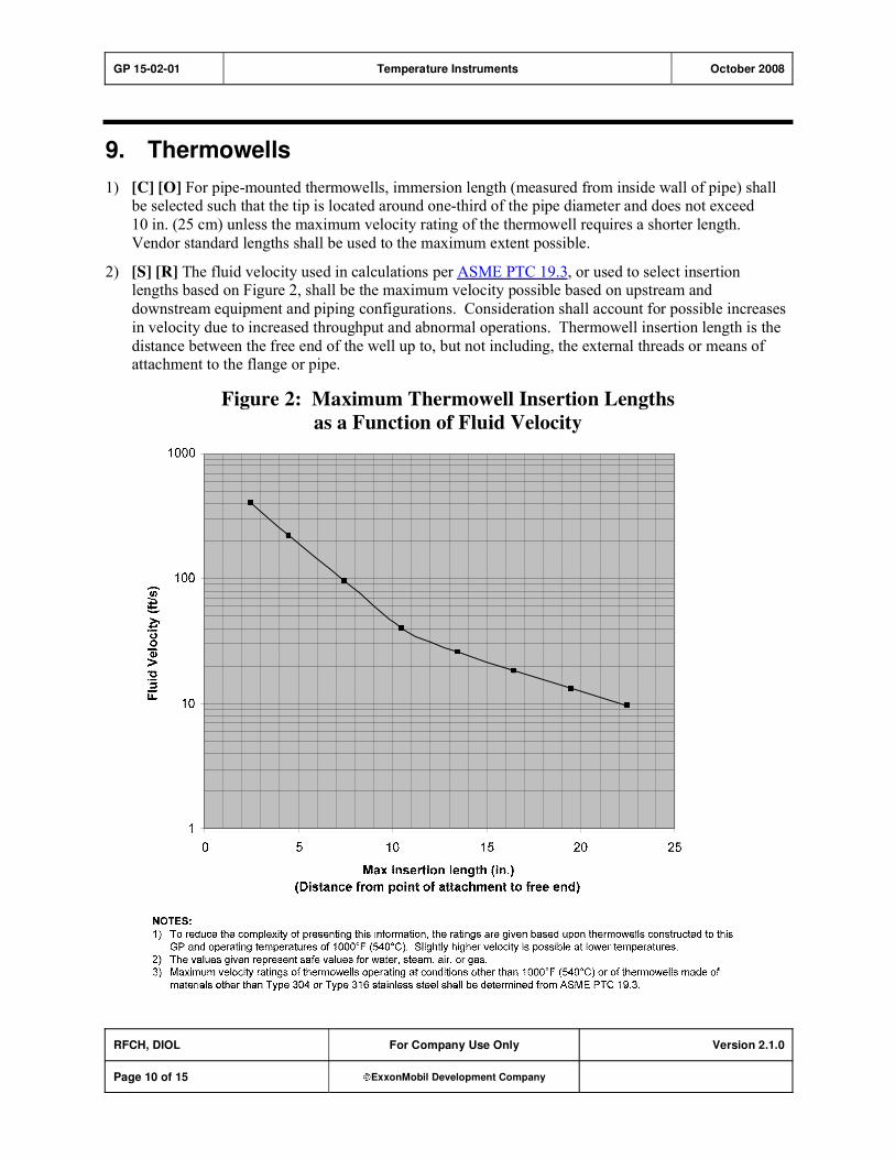
GP 15-02-01 Temperature Instruments October 2008
RFCH, DIOL For Company Use Only Version 2.1.0
Page 10 of 15 ExxonMobil Development Company
9. Thermowells
1) [C] [O] For pipe-mounted thermowells, immersion length (measured from inside wall of pipe) shall be selected such that the tip is located around one-third of the pipe diameter and does not exceed
10 in. (25 cm) unless the maximum velocity rating of the thermowell requires a shorter length.
Vendor standard lengths shall be used to the maximum extent possible.
2) [S] [R] The fluid velocity used in calculations per ASME PTC 19.3, or used to select insertion lengths based on Figure 2, shall be the maximum velocity possible based on upstream and
downstream equipment and piping configurations. Consideration shall account for possible increases
in velocity due to increased throughput and abnormal operations. Thermowell insertion length is the
distance between the free end of the well up to, but not including, the external threads or means of attachment to the flange or pipe.
Figure 2: Maximum Thermowell Insertion Lengths
as a Function of Fluid Velocity
GP 15-02-01 Temperature Instruments October 2008
RFCH, DIOL For Company Use Only Version 2.1.0
Page 11 of 15 ExxonMobil Development Company
3) [O] A trade-off exists between the length of well for strength and exposure to measurement
inaccuracy. Static error can be generated due to conduction to the portion of the well exposed to
ambient cooling. Dynamic error can be generated due to the mass of the well between the fluid and the sensing element. Both of these issues are influenced by well length and fluid velocity. Refer to
ASME PTC 19.3 for a detailed means of calculating errors and methods of minimizing the effects.
4) [A] [R] Where flanged thermowells may be subject to damage due to high vibration and the
thermowell cannot be relocated (or shortened because of resultant temperature inaccuracies), a velocity collar may be used with approval by the Owner's Engineer. Where used, these velocity
collars shall be installed in a machined stand-off where the annular space between the ID of the stand-
off and the OD of the thermowell collar is better than 1 mm.
5) Thermowell connections for general service applications shall be per the following:
a) Flanged connections shall be used in services where any of the following conditions apply:
i) The normal operating temperature is equal to or greater than 400 F (205 C).
ii) The pressure-to-temperature design conditions require an ASME Class 900 (or greater)
flange.
iii) Removal of the thermowell for maintenance is expected.
b) Threaded connections may be used where flanged connections are not required.
6) [R] Thermowells for general service shall have the following construction:
a) [A] Threaded thermowells shall be machined from solid bar stock with a process connection of
NPT 1 in. (25 mm) external taper-threaded. Welded thermowell construction for atmospheric
storage tanks is acceptable with approval by the Owner's Engineer.
b) Connection size for the thermocouple entry shall be NPT 1/2 in. (12.5 mm).
c) [*] For flanged connections, the minimum flange size shall be NPS 2 in. (50 mm) ASME B16.5.
Flange rating, face, and finish shall be specified. Flanged thermowells may be machined from solid bar stock or, alternatively, may be fabricated from a thermowell and flange similar to panel
B, Figure 26, "Thermowell Installation," of API RP 551. The weld must be a full penetration
weld as shown.
d) Thermowell dimensions shall be as follows:
i) [*] Length�insertion length and extension length will be specified.
ii) OD�straight taper from 11/16 in. (27 mm) OD at the base of thread (or point of flange
attachment) to a minimum of 5/8 in. (16 mm) at the tip.
iii) Bore�0.26 in. (6.6 mm).
iv) Tip Thickness�1/4 in. (6 mm) minimum.
7) [R] Thermowells in erosive service shall have heavier wall and tip thickness. Thermowells shall
taper from 11/16 in. OD (27 mm) at base of the thread to
7/8 in. (22.2 mm) at the tip. Tip thickness
shall be 5/8 in. (16 mm).
8) [R] [I] Thermowells in coking and/or erosive service shall be installed from the top of pipe whenever possible.
9) [R] Test thermowells shall meet all the requirements of thermowells in continuous service and shall
be provided with a drilled captive brass plug.
10) The thermowell material identification shall be clearly stamped on the body or flange.
GP 15-02-01 Temperature Instruments October 2008
RFCH, DIOL For Company Use Only Version 2.1.0
Page 12 of 15 ExxonMobil Development Company
11) [R] All alloy thermowells require 100 percent PMI verification per GP 18-12-01.
12) [*] Typical material of construction for thermowells will be 304 or 316 stainless steel. However, the
materials of construction shall have corrosion resistance and temperature rating equal to or better than the process piping line classification or vessel materials. Potential stress cracking of stainless steel
should also be considered.
13) [A] [R] With approval by the Owner's Engineer, two-piece thermowell construction or pipe wells
with spun and welded end may be used for gas phase measurement where long insertions are necessary (in firebox and flue gas areas in heaters, boilers, furnaces, stacks, and large vessels).
14) [S] Thermowells installed in a threaded connection shall be seal welded to prevent removal of the
thermowell.
10. Inspection and Testing
1) [S] All thermowells shall have ratings clearly above the design pressure of the associated piping,
normally no less than 3000 psi (20700 kPa) rated. All thermowells shall be specified on the data sheets as certified pressure tested to confirm their rating by Manufacturer/Vendor.
2) [S] Flanged thermowells shall also be certified pressure tested externally, based on the flange rating,
under requirements of ASME B31.3 or ASME B31.8 as applicable. Alternatively, if external testing
is not readily available, the thermowell may be installed prior to pressure testing of the associated
piping and thereby tested with the piping to meet ASME standards.
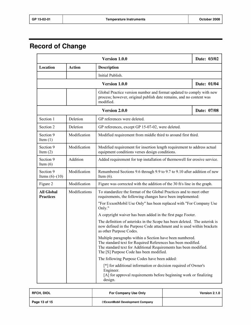
GP 15-02-01 Temperature Instruments October 2008
RFCH, DIOL For Company Use Only Version 2.1.0
Page 13 of 15 ExxonMobil Development Company
Record of Change
Version 1.0.0 Date: 03/02
Location Action Description
Initial Publish.
Version 1.0.0 Date: 01/04
Global Practice version number and format updated to comply with new
process; however, original publish date remains, and no content was
modified.
Version 2.0.0 Date: 07/08
Section 1 Deletion GP references were deleted.
Section 2 Deletion GP references, except GP 15-07-02, were deleted.
Section 9
Item (1)
Modification Modified requirement from middle third to around first third.
Section 9
Item (2)
Modification Modified requirement for insertion length requirement to address actual
equipment conditions verses design conditions.
Section 9
Item (6)
Addition Added requirement for top installation of thermowell for erosive service.
Section 9
Items (6)�(10)
Modification Renumbered Sections 9.6 through 9.9 to 9.7 to 9.10 after addition of new
Item (6).
Figure 2 Modification Figure was corrected with the addition of the 30 ft/s line in the graph.
All Global
Practices
Modifications To standardize the format of the Global Practices and to meet other
requirements, the following changes have been implemented:
"For ExxonMobil Use Only" has been replaced with "For Company Use
Only."
A copyright waiver has been added in the first page Footer.
The definition of asterisks in the Scope has been deleted. The asterisk is
now defined in the Purpose Code attachment and is used within brackets
as other Purpose Codes.
Multiple paragraphs within a Section have been numbered.
The standard text for Required References has been modified.
The standard text for Additional Requirements has been modified. The [S] Purpose Code has been modified.
The following Purpose Codes have been added:
[*] for additional information or decision required of Owner's
Engineer.
[A] for approval requirements before beginning work or finalizing
design.

GP 15-02-01 Temperature Instruments October 2008
RFCH, DIOL For Company Use Only Version 2.1.0
Page 14 of 15 ExxonMobil Development Company
Version 2.1.0 Date: 10/08
General From this version onward, revision bars in the right margin will be used
to identify technical changes from the last version of the GP.
Section 1.1 Addition Added reference GP 18-12-02.
Section 1.3 Addition Added references ASME B31.3 and ASME B31.8.
Section 3,
Items (3), (4),
and (5)
Modification Added wording to clarify intent.
Section 4,
Item (5)
Modification Added wording to clarify the use of Figure 1.
Figure 1 Modification Changed Figure 1 and associated installation and welding instructions to
reflect best practice installations for TMTs.
Table 1 Modification Changed Table 1 and associated notes to reflect best practice installations for TMTs.
Section9, Item (2)
Modification Modified wording to conform to Figure 2 "velocity vs. insertion length"; also modified rationale wording for clarity.
Figure 2 Modification Corrected figure and updated notes.
Section 9,
Item (3)
Modification Added wording on required consideration for accuracy versus strength.
Section 9,
Item (4)
Addition Added restricted use of velocity collars for special circumstances.
Section 9,
Item (8)
Modification Added coking service to erosive service statement.
Section 9, Item (11)
Addition Added requirements for PMI with reference to GP 18-12-01.
Section 9, Item (12)
Modification Changed wording to include "corrosion resistance and temperature rating equal to or better than the process piping line" and "potential stress
cracking of stainless steel should also be considered."
Section 9,
Item (13)
Addition Added rationale.
Section 9,
Item (14)
Addition Added seal welding for threaded thermowells.
Section 10,
Item (1)
Modification Modified pressure rating to 3000 psi.
Section 10,
Item (2)
Modification Modified flange testing to conform to ASME B31.3 and B31.8.

GP 15-02-01 Temperature Instruments October 2008
RFCH, DIOL For Company Use Only Version 2.1.0
Page 15 of 15 ExxonMobil Development Company
Attachment: Purpose Code Definitions
Code Description
* Assigned to paragraphs that require the Owner's Engineer to provide additional information or
make a decision.
A Assigned to paragraphs that require approval from the Owner's Engineer before the work may
proceed or the design is finalized.
C Assigned to paragraphs whose primary purpose is reduced costs. Reduced cost in this context
refers to initial investment cost and does not include life cycle cost considerations. Life cycle
cost considerations are captured under reliability, maintainability, or operability purpose codes.
E Assigned to paragraphs whose primary purpose is driven by environmental considerations. Environmental considerations typically include specifications intended to protect against
emissions/leakage to the air, water, and/or soil. Deviations from the specifications contained
in such paragraphs require formal review and approval according to local environmental policy.
I Assigned to paragraphs that provide only clarifying information, such as Scope statements,
definitions of terms, etc.
M Assigned to paragraphs whose primary purpose is to provide for maintainability of equipment or systems. Maintainability provisions are those that facilitate the performance of maintenance
on equipment/systems either during downtimes or during onstream operations.
O Assigned to paragraphs whose primary purpose is to assure operability of equipment or
systems. Operability is the ability of the equipment/system to perform satisfactorily even though conditions are off-design, such as during start-ups, process swings, subcomponent
malfunction, etc.
R Assigned to paragraphs whose primary purpose is to improve or assure the reliability of
equipment or systems. Reliability is a measure of the ability of equipment/systems to operate without malfunction or failure between planned maintenance interventions.
S Assigned to paragraphs containing specifications/guidance where the primary purpose is the
avoidance of incidents impacting personnel safety, operational safety, and the public in general and/or involving responses to emergency situations. Any deviation from the specifications
contained in such designated paragraphs requires formal review and approval according to
local safety policy.
Personnel Safety: Refers to incident-related personnel injuries or illness, e.g., burns, cuts, abrasions, inhalation of or exposure to dangerous substances, etc., that
could result in medical treatment, restricted work, lost-time incidents, or
fatalities.
Operational
Safety:
Refers to the prevention and control of process releases, fires, and/or
explosions that could result in damage to equipment, process disruption,
or personnel injury or illness.

GP 15-03-01 Pressure Instruments October 2008
Refining/Chemicals, Upstream, Downstream Imperial Oil
For Company Use Only Version 1.1.0
Page 1 of 7 ExxonMobil Development Company
Copyright Waiver ExxonMobil Development Company and ExxonMobil Pipeline Company hereby license the use of ExxonMobil Engineering Practices System (EMEPS) Global Practices (GPs) for use by any ExxonMobil division, subsidiary, or more-than-50%-owned affiliate. The GPs may be downloaded and modified as necessary for project and affiliate use. Written permission from ExxonMobil Development Company or ExxonMobil Pipeline Company is not required. However, any modified GPs must be renumbered to a project-specific or affiliate-specific number to distinguish them from the GPs on the EMEPS web site. ExxonMobil operated joint ventures may utilize GPs to create project-specific or location-specific specifications. It is the responsibility of individual affiliate or joint venture to ensure that the use of GPs and their derivatives is limited to joint venture related business and not disclosed or used outside the JV without appropriate EM management approval.
Pressure Instruments
GP 15-03-01
Scope
[I] This Global Practice (GP) covers the design and selection of pressure instruments.
GP 15-03-01 Pressure Instruments October 2008
RFCH, UPST, DIOL For Company Use Only Version 1.1.0
Page 2 of 7 ExxonMobil Development Company
Table of Contents
1. Required References ............................................................................................ 3
1.1. Global Practices–ExxonMobil Engineering Practices ................................... 3
1.2. API–American Petroleum Institute................................................................ 3
1.3. ASME–American Society of Mechanical Engineers ..................................... 3
2. Design .................................................................................................................... 3
3. Indicating Pressure Gauges................................................................................. 4
4. Pneumatic Air Receiver Indicating Gauges ........................................................ 5
5. Pressure Switches ................................................................................................ 5
6. Process Connections............................................................................................ 5
Record of Change ......................................................................................................... 6
Attachment: Purpose Code Definitions...................................................................... 7

GP 15-03-01 Pressure Instruments October 2008
RFCH, UPST, DIOL For Company Use Only Version 1.1.0
Page 3 of 7 ExxonMobil Development Company
1. Required References
[I] This Section lists the Practices, codes, standards, specifications, and publications that shall be used with this document. Unless otherwise specified herein, use the latest edition.
1.1. Global Practices–ExxonMobil Engineering Practices
GP 03-06-01 Piping for Instruments
GP 15-06-01 Electronic and Pneumatic Instruments
1.2. API–American Petroleum Institute
API RP 551 Process Measurement Instrumentation
1.3. ASME–American Society of Mechanical Engineers
ASME B1.20.1 Pipe Threads, General Purpose (Inch)
ASME B40.100 Pressure Gauges and Gauge Attachments
2. Design
1) [O] Pressure range shall be such that normal pressure will be in the middle third of the span.
2) [S] [R] Instruments shall have over-range protection to the maximum pressure to which they may be
exposed. Instruments exposed to vacuum shall have under-range protection to full vacuum.
3) [S] Instruments in flammable or toxic service shall not have pressure-containing parts of low melting
point materials, such as aluminum or brass.
4) [A] [R] All wetted and pressure-containing parts shall meet the material requirements of the process
piping to which the instrument is connected. External diaphragm seals may be used with approval by the Owner's Engineer. In process streams containing hydrogen, the use of gold-plated diaphragms
shall be considered.
5) [O] Scales and displays (local or remote) shall read in engineering units.
6) [A] Transmitter design and performance shall meet the requirements of GP 15-06-01 unless otherwise specified by the Owner's Engineer.
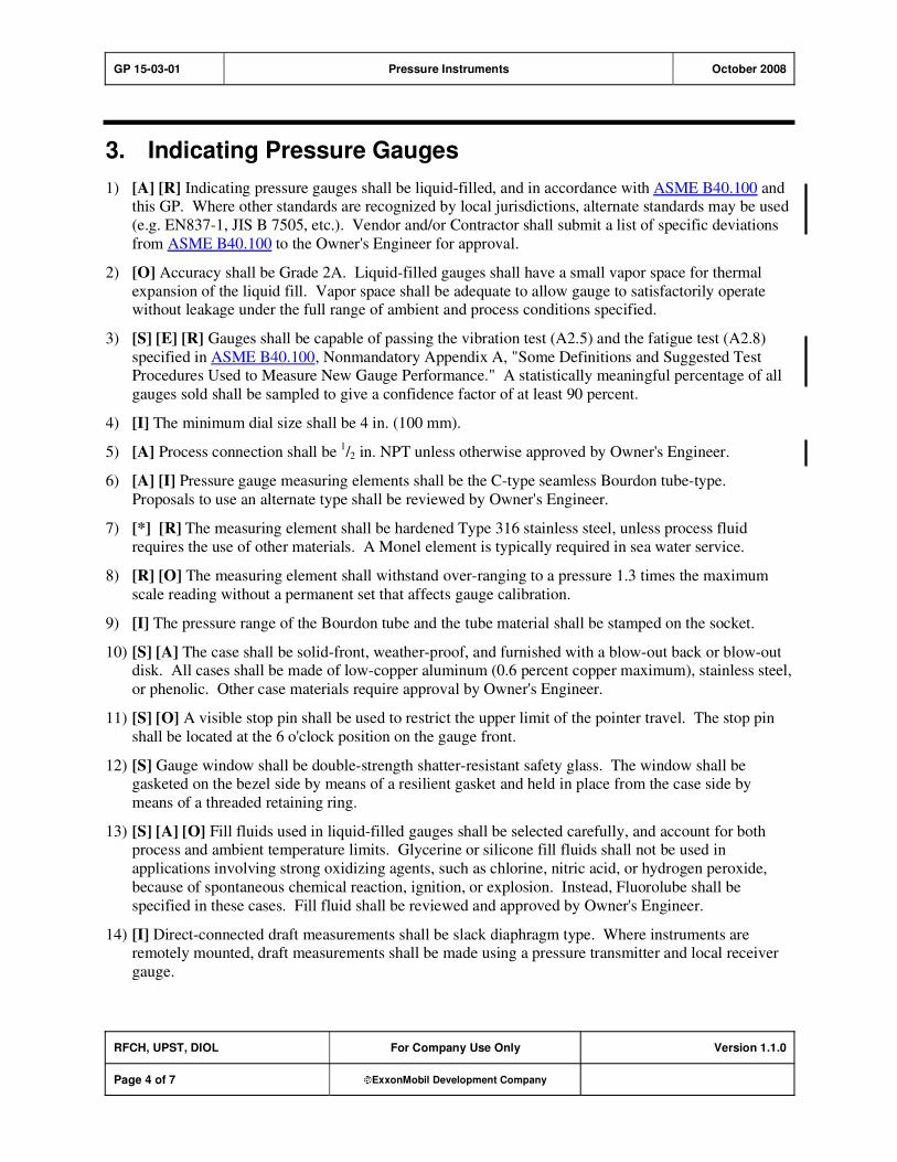
GP 15-03-01 Pressure Instruments October 2008
RFCH, UPST, DIOL For Company Use Only Version 1.1.0
Page 4 of 7 ExxonMobil Development Company
3. Indicating Pressure Gauges
1) [A] [R] Indicating pressure gauges shall be liquid-filled, and in accordance with ASME B40.100 and this GP. Where other standards are recognized by local jurisdictions, alternate standards may be used
(e.g. EN837-1, JIS B 7505, etc.). Vendor and/or Contractor shall submit a list of specific deviations
from ASME B40.100 to the Owner's Engineer for approval.
2) [O] Accuracy shall be Grade 2A. Liquid-filled gauges shall have a small vapor space for thermal
expansion of the liquid fill. Vapor space shall be adequate to allow gauge to satisfactorily operate without leakage under the full range of ambient and process conditions specified.
3) [S] [E] [R] Gauges shall be capable of passing the vibration test (A2.5) and the fatigue test (A2.8)
specified in ASME B40.100, Nonmandatory Appendix A, "Some Definitions and Suggested Test Procedures Used to Measure New Gauge Performance." A statistically meaningful percentage of all
gauges sold shall be sampled to give a confidence factor of at least 90 percent.
4) [I] The minimum dial size shall be 4 in. (100 mm).
5) [A] Process connection shall be 1/2 in. NPT unless otherwise approved by Owner's Engineer.
6) [A] [I] Pressure gauge measuring elements shall be the C-type seamless Bourdon tube-type.
Proposals to use an alternate type shall be reviewed by Owner's Engineer.
7) [*] [R] The measuring element shall be hardened Type 316 stainless steel, unless process fluid
requires the use of other materials. A Monel element is typically required in sea water service.
8) [R] [O] The measuring element shall withstand over-ranging to a pressure 1.3 times the maximum
scale reading without a permanent set that affects gauge calibration.
9) [I] The pressure range of the Bourdon tube and the tube material shall be stamped on the socket.
10) [S] [A] The case shall be solid-front, weather-proof, and furnished with a blow-out back or blow-out disk. All cases shall be made of low-copper aluminum (0.6 percent copper maximum), stainless steel,
or phenolic. Other case materials require approval by Owner's Engineer.
11) [S] [O] A visible stop pin shall be used to restrict the upper limit of the pointer travel. The stop pin
shall be located at the 6 o'clock position on the gauge front.
12) [S] Gauge window shall be double-strength shatter-resistant safety glass. The window shall be gasketed on the bezel side by means of a resilient gasket and held in place from the case side by
means of a threaded retaining ring.
13) [S] [A] [O] Fill fluids used in liquid-filled gauges shall be selected carefully, and account for both process and ambient temperature limits. Glycerine or silicone fill fluids shall not be used in
applications involving strong oxidizing agents, such as chlorine, nitric acid, or hydrogen peroxide,
because of spontaneous chemical reaction, ignition, or explosion. Instead, Fluorolube shall be
specified in these cases. Fill fluid shall be reviewed and approved by Owner's Engineer.
14) [I] Direct-connected draft measurements shall be slack diaphragm type. Where instruments are remotely mounted, draft measurements shall be made using a pressure transmitter and local receiver
gauge.

GP 15-03-01 Pressure Instruments October 2008
RFCH, UPST, DIOL For Company Use Only Version 1.1.0
Page 5 of 7 ExxonMobil Development Company
4. Pneumatic Air Receiver Indicating Gauges
1) [S] [O] A stop pin is required on all pneumatic receiver gauges at zero pressure indication.
2) [S] Receiver gauges are gauges designed to measure pneumatic signals (e.g., 3 to 15 PSI) and present the pressure in engineering units. This presents a unique hazard when they are directly connected to
the process. Receiver gauges must be uniquely and distinctly identified (e.g., unique color, ¼ in. NPT
connection, tagged or placarded, or similar method).
5. Pressure Switches
1) [R] Electrical switch shall have contact rating of 115 VAC, 2 amperes minimum. Any switch that initiates an inductive device, such as a trip coil of a motor starter, shall have a minimum inductance
contact rating suitable for that service.
2) [S] [R] Switch contacts shall be hermetically sealed.
3) [O] Pressure switches shall have an adjustable set point or differential gap with a reference or
calibrated scale. Where explosionproof, flameproof or weatherproof housings are used, an internal scale is acceptable; however, an external scale with protective covering is preferred for general-
purpose housings.
4) [R] For direct process-connected switches, electrical entry and electrical connections shall be completely isolated from process connections and components in contact with the process.
5) [R] Where tamper-proof switches are required, they shall have internally adjustable set points or
locking devices on the external set point adjustment.
6. Process Connections
Instruments shall be mounted and connected to the process in accordance with GP 03-06-01.
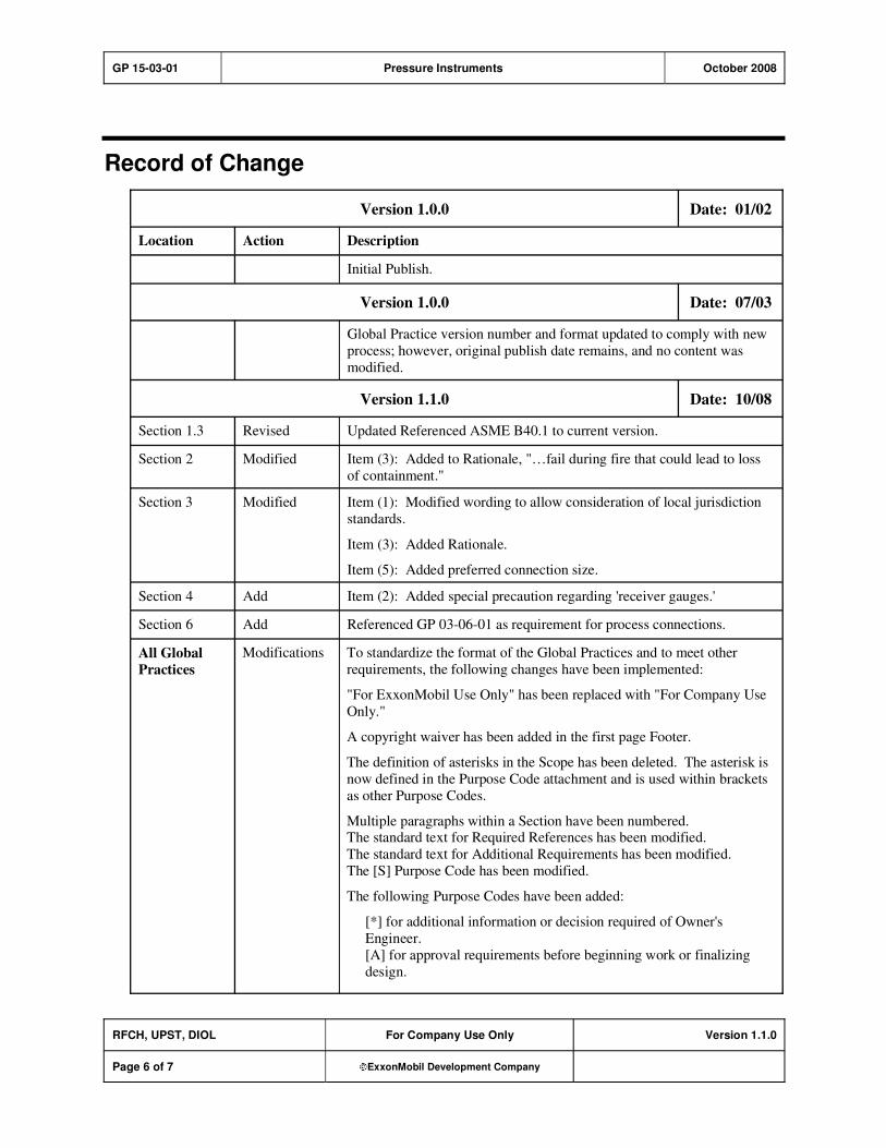
GP 15-03-01 Pressure Instruments October 2008
RFCH, UPST, DIOL For Company Use Only Version 1.1.0
Page 6 of 7 ExxonMobil Development Company
Record of Change
Version 1.0.0 Date: 01/02
Location Action Description
Initial Publish.
Version 1.0.0 Date: 07/03
Global Practice version number and format updated to comply with new
process; however, original publish date remains, and no content was
modified.
Version 1.1.0 Date: 10/08
Section 1.3 Revised Updated Referenced ASME B40.1 to current version.
Section 2 Modified Item (3): Added to Rationale, "…fail during fire that could lead to loss
of containment."
Section 3 Modified Item (1): Modified wording to allow consideration of local jurisdiction
standards.
Item (3): Added Rationale.
Item (5): Added preferred connection size.
Section 4 Add Item (2): Added special precaution regarding 'receiver gauges.'
Section 6 Add Referenced GP 03-06-01 as requirement for process connections.
All Global
Practices
Modifications To standardize the format of the Global Practices and to meet other
requirements, the following changes have been implemented:
"For ExxonMobil Use Only" has been replaced with "For Company Use
Only."
A copyright waiver has been added in the first page Footer.
The definition of asterisks in the Scope has been deleted. The asterisk is
now defined in the Purpose Code attachment and is used within brackets
as other Purpose Codes.
Multiple paragraphs within a Section have been numbered. The standard text for Required References has been modified.
The standard text for Additional Requirements has been modified.
The [S] Purpose Code has been modified.
The following Purpose Codes have been added:
[*] for additional information or decision required of Owner's
Engineer.
[A] for approval requirements before beginning work or finalizing
design.

GP 15-03-01 Pressure Instruments October 2008
RFCH, UPST, DIOL For Company Use Only Version 1.1.0
Page 7 of 7 ExxonMobil Development Company
Attachment: Purpose Code Definitions
Code Description
* Assigned to paragraphs that require the Owner's Engineer to provide additional information or
make a decision.
A Assigned to paragraphs that require approval from the Owner's Engineer before the work may
proceed or the design is finalized.
C Assigned to paragraphs whose primary purpose is reduced costs. Reduced cost in this context
refers to initial investment cost and does not include life cycle cost considerations. Life cycle
cost considerations are captured under reliability, maintainability, or operability purpose codes.
E Assigned to paragraphs whose primary purpose is driven by environmental considerations. Environmental considerations typically include specifications intended to protect against
emissions/leakage to the air, water, and/or soil. Deviations from the specifications contained
in such paragraphs require formal review and approval according to local environmental policy.
I Assigned to paragraphs that provide only clarifying information, such as Scope statements,
definitions of terms, etc.
M Assigned to paragraphs whose primary purpose is to provide for maintainability of equipment or systems. Maintainability provisions are those that facilitate the performance of maintenance
on equipment/systems either during downtimes or during onstream operations.
O Assigned to paragraphs whose primary purpose is to assure operability of equipment or
systems. Operability is the ability of the equipment/system to perform satisfactorily even though conditions are off-design, such as during start-ups, process swings, subcomponent
malfunction, etc.
R Assigned to paragraphs whose primary purpose is to improve or assure the reliability of
equipment or systems. Reliability is a measure of the ability of equipment/systems to operate without malfunction or failure between planned maintenance interventions.
S Assigned to paragraphs containing specifications/guidance where the primary purpose is the
avoidance of incidents impacting personnel safety, operational safety, and the public in general and/or involving responses to emergency situations. Any deviation from the specifications
contained in such designated paragraphs requires formal review and approval according to
local safety policy.
Personnel Safety: Refers to incident-related personnel injuries or illness, e.g., burns, cuts, abrasions, inhalation of or exposure to dangerous substances, etc., that
could result in medical treatment, restricted work, lost-time incidents, or
fatalities.
Operational
Safety:
Refers to the prevention and control of process releases, fires, and/or
explosions that could result in damage to equipment, process disruption,
or personnel injury or illness.

GP 18-07-01 Welding Procedures August 2003
Refining/Chemicals For ExxonMobil Use Only Version 2.0.0
Page 1 of 15 ExxonMobil Development Company
Welding Procedures
GP 18-07-01
Scope
1) [R] This ExxonMobil Global Practice (GP) governs welding and welding qualifications.
2) [I] API RP 582, 1st Edition, March 2001, titled “Welding Guidelines for the Chemical, Oil, and Gas
Industries," as amended by this GP, defines the minimum requirements and practices for welding and welding qualification. Unless otherwise noted, all the API paragraphs shall be considered mandatory.
3) [I] Only the paragraphs that are amended are listed in this GP. For convenience, the nature of the
amendment is noted in the beginning of each paragraph as follows:
a) Addition Specifies paragraphs that do not appear in the API RP, and additions to the corresponding API paragraph.
b) Exception Specifies paragraphs that modify or completely replace the
corresponding API paragraph.
4) [I] An asterisk (*) indicates that a decision by Purchaser is required or that additional information is
furnished by Purchaser.

GP 18-07-01 Welding Procedures August 2003
RFCH For ExxonMobil Use Only Version 2.0.0
Page 2 of 15 ExxonMobil Development Company
Table of Contents
1. Required References ............................................................................................ 3
1.1. Global Practices–ExxonMobil Engineering Practices ................................... 3
1.2. API-American Petroleum Institute................................................................. 3
2. Revisions to API RP 582 ....................................................................................... 3
Revisions to Section 3: Definitions ............................................................................ 3
Revisions to Section 4: General Welding Requirements.......................................... 3
Revisions to Section 5: Welding Processes .............................................................. 4
Revisions to Section 6: Welding Consumables......................................................... 5
Revisions to Section 7: Shielding and Purging Gases ............................................. 7
Revisions to Section 8: Preheating and Interpass Temperature.............................. 7
Revisions to Section 9: Postweld Heat Treatment (PWHT) ...................................... 8
Revisions to Section 10: Cleaning and Surface Preparation ................................... 8
Revisions to Section 11: Special Procedure Qualification Requirements/Testing. 9
Revisions to Section 12: Other Items......................................................................... 9
Revision to Appendix A: Welding Consumables for SMAW .................................... 9
Revision to Appendix B: Weld Overlay and Clad Restoration ................................. 9
Record of Change ....................................................................................................... 14
Attachment: Purpose Codes Definitions.................................................................. 15

GP 18-07-01 Welding Procedures August 2003
RFCH For ExxonMobil Use Only Version 2.0.0
Page 3 of 15 ExxonMobil Development Company
1. Required References
* This Section lists Practices and Standards that are generically referenced and assumed to be a part of this document. Unless otherwise specified herein, use the latest edition.
1.1. Global Practices–ExxonMobil Engineering Practices
GP 03-18-01 Piping Fabrication Shop or Field
GP 18-10-01 Additional Requirements for Materials
1.2. API-American Petroleum Institute
API RP 582 Welding Guidelines for the Chemical, Oil, and Gas Industries
2. Revisions to API RP 582
[I] All headings contained herein correspond to paragraph numbering within API RP 582 and reflect
additions and exceptions to the recommended practice. All provisions not modified or deleted remain in
force.
Revisions to Section 3: Definitions
3. Additions: Definitions
Back cladding A localized weld overlay operation between two integrally clad or weld overlaid sections. This process is also known as "clad restoration."
Effective depth The thickness of weld overlay or back cladding having the specified
chemical composition.
Total depth The total thickness of weld overlay or back cladding.
Weld overlay
(surfacing)
A deposition of one or more layers of a dissimilar weld metal to the surface of a base material in an effort to improve the corrosion or wear
resistance properties of the surface.
Revisions to Section 4: General Welding Requirements
[R] Basis for rejection of WPS's shall be noncompliance with this practice, failure to meet applicable
codes, or violation of industry practice.
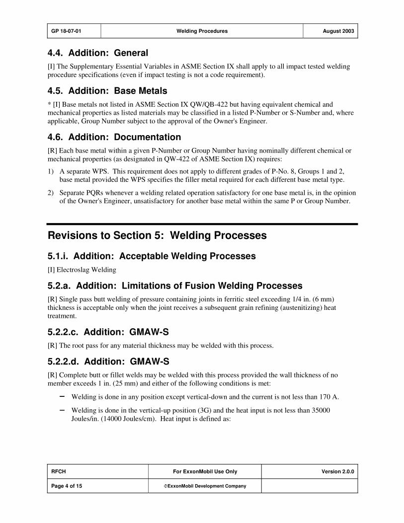
GP 18-07-01 Welding Procedures August 2003
RFCH For ExxonMobil Use Only Version 2.0.0
Page 4 of 15 ExxonMobil Development Company
4.4. Addition: General
[I] The Supplementary Essential Variables in ASME Section IX shall apply to all impact tested welding
procedure specifications (even if impact testing is not a code requirement).
4.5. Addition: Base Metals
* [I] Base metals not listed in ASME Section IX QW/QB-422 but having equivalent chemical and mechanical properties as listed materials may be classified in a listed P-Number or S-Number and, where
applicable, Group Number subject to the approval of the Owner's Engineer.
4.6. Addition: Documentation
[R] Each base metal within a given P-Number or Group Number having nominally different chemical or
mechanical properties (as designated in QW-422 of ASME Section IX) requires:
1) A separate WPS. This requirement does not apply to different grades of P-No. 8, Groups 1 and 2, base metal provided the WPS specifies the filler metal required for each different base metal type.
2) Separate PQRs whenever a welding related operation satisfactory for one base metal is, in the opinion of the Owner's Engineer, unsatisfactory for another base metal within the same P or Group Number.
Revisions to Section 5: Welding Processes
5.1.i. Addition: Acceptable Welding Processes
[I] Electroslag Welding
5.2.a. Addition: Limitations of Fusion Welding Processes
[R] Single pass butt welding of pressure containing joints in ferritic steel exceeding 1/4 in. (6 mm)
thickness is acceptable only when the joint receives a subsequent grain refining (austenitizing) heat treatment.
5.2.2.c. Addition: GMAW-S
[R] The root pass for any material thickness may be welded with this process.
5.2.2.d. Addition: GMAW-S
[R] Complete butt or fillet welds may be welded with this process provided the wall thickness of no
member exceeds 1 in. (25 mm) and either of the following conditions is met:
Welding is done in any position except vertical-down and the current is not less than 170 A.
Welding is done in the vertical-up position (3G) and the heat input is not less than 35000
Joules/in. (14000 Joules/cm). Heat input is defined as:

GP 18-07-01 Welding Procedures August 2003
RFCH For ExxonMobil Use Only Version 2.0.0
Page 5 of 15 ExxonMobil Development Company
Equation 1: Heat Input
minute)percmor(in.speedtravel
60 voltageamperage
5.2.6.1 Addition: SAW
[R] Requalification is also required when the welding flux manufacturer is changed.
5.2.7. Addition: Gas Tungsten Arc Welding (GTAW)
1) [R] Manual GTAW (TIG) welding shall be used with the addition of filler metal and high frequency starting equipment or equal.
2) [R] For GTAW (TIG), the addition or deletion of consumable inserts for single welded butt joints
(without backing devices) requires separate WPS(s) and PQR(s).
Revisions to Section 6: Welding Consumables
6.1.5. Addition: General
For electroslag welding, the AWS electrode-flux classification, and the flux manufacturer and trade name
shall be specified in the PQR and WPS.
6.1.6. Addition: General
* [R] Unless specifically authorized by Purchaser, filler metals and consumables shall be used only for
the primary material and process applications recommended in the AWS filler metal specification or by
its manufacturer, e.g., filler metals designed for "single pass welding" shall not be used for multi-pass joints. SAW fluxes designated for non-PWHT applications shall not be used for PWHT applications.
6.1.7. Addition: General
[R] When joining similar metals, the deposited weld metal shall match the chemistry and the mechanical
properties of the base metal as closely as possible.
* Whenever the minimum mechanical properties of the deposited weld metal fail to meet the minimum mechanical properties of the base metal, or whenever the nominal chemistry of the deposited weld metal
differs from the nominal chemistry of the base metal, the Vendor's proposal to use such weld metal shall
be submitted to Purchaser for approval by the Owner's Engineer.
6.1.8. Addition: General
[R] When the thickness of carbon or low alloy steel base metal exceeds 1/2 in. (13 mm), groove or fillet
welds shall be made with filler metals producing low hydrogen deposits. However, cellulose or rutile-
type coated electrodes may be used for the root pass of a groove weld regardless of the base metal thickness. Rutile SMAW electrodes shall not be used for fill and cap passes on pressure vessels and
pressure piping.

GP 18-07-01 Welding Procedures August 2003
RFCH For ExxonMobil Use Only Version 2.0.0
Page 6 of 15 ExxonMobil Development Company
6.1.9. Addition: General
[R] Requalification is required whenever:
1) [R] The wire chemistry for ferritic steels is changed from one AWS classification to any other
classification or to a chemical composition not covered by the AWS filler metal specifications.
2) [R] Flux cored electrodes are changed from one AWS classification to another, electrodes are not
classified by AWS or electrodes are specified with supplementary requirements. Requalification is
not required for a change in the position designator from EX0T-X to EX1T-X and vice versa.
3) [R] The chemical composition of the weld deposit is changed from one A-Number to any other A-
Number in QW/QB 442 of ASME Section IX including a change from A-1 to A-2 and vice versa.
6.2.2. Exception: Dissimilar Welding
[R] When joining ferritic steels (P-1 through P-5) to martensitic stainless steels (P-6), ferritic stainless
steels (P-7), or austenitic stainless steels (P-8), the filler metal shall be selected based on the following:
1) Nickel-based alloy filler metal shall be selected using the design conditions shown in Table 6-1,
except the maximum design temperature for AWS Classes ERNiCrMo-3 type filler metals in sulfur
environments shall be 900 F (480 C).
2) Type 309 and Type 309L may be used for design temperatures not exceeding 600 F (315 C). Type 309Cb shall not be used when PWHT is required, except for weld overlay.
3) For design conditions exceeding the limits stated in 6.2.2 items a and b, the filler metal selection shall
be reviewed with the Owner's Engineer.
4) Type 310 (25 Cr-20 Ni) stainless steel filler metals shall not be used.
5) AWS Class ERNiCrFe-6 filler metals shall not be used.
6.3.1. Additions: Austenitic Stainless Steel Welding
[I]*Base metal and filler metal combinations not meeting the recommendations of Appendix A Table A-2
shall be submitted for approval by the Owner's Engineer.
6.5.4. Exception: Submerged Arc Welding
[R] Reprocessed flux or re-crushed slag shall not be used for submerged arc welding of pressure-
containing parts such as pressure vessels, piping, and atmospheric storage tanks. Use of such materials is permitted for submerged arc welding of structural and non-code components provided all of the following
requirements are met:
1) Approval by Owner's Engineer.
2) Separate and distinct markings identifying the re-crusher and his trade designation.
3) Separate WPS(s) and PQR(s).
4) Testing per AWS A5.17/A5.17M, AWS A5.23/A5.23M, or equivalent specification.
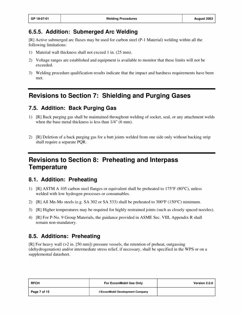
GP 18-07-01 Welding Procedures August 2003
RFCH For ExxonMobil Use Only Version 2.0.0
Page 7 of 15 ExxonMobil Development Company
6.5.5. Addition: Submerged Arc Welding
[R] Active submerged arc fluxes may be used for carbon steel (P-1 Material) welding within all the
following limitations:
1) Material wall thickness shall not exceed 1 in. (25 mm).
2) Voltage ranges are established and equipment is available to monitor that these limits will not be exceeded.
3) Welding procedure qualification results indicate that the impact and hardness requirements have been
met.
Revisions to Section 7: Shielding and Purging Gases
7.5. Addition: Back Purging Gas
1) [R] Back purging gas shall be maintained throughout welding of socket, seal, or any attachment welds when the base metal thickness is less than 1/4" (6 mm).
2) [R] Deletion of a back purging gas for a butt joints welded from one side only without backing strip shall require a separate PQR.
Revisions to Section 8: Preheating and Interpass Temperature
8.1. Addition: Preheating
1) [R] ASTM A 105 carbon steel flanges or equivalent shall be preheated to 175 F (80 C), unless
welded with low hydrogen processes or consumables.
2) [R] All Mn-Mo steels (e.g. SA 302 or SA 533) shall be preheated to 300 F (150 C) minimum.
3) [R] Higher temperatures may be required for highly restrained joints (such as closely spaced nozzles).
4) [R] For P-No. 9 Group Materials, the guidance provided in ASME Sec. VIII, Appendix R shall
remain non-mandatory.
8.5. Additions: Preheating
[R] For heavy wall (>2 in. [50 mm]) pressure vessels, the retention of preheat, outgassing (dehydrogenation) and/or intermediate stress relief, if necessary, shall be specified in the WPS or on a
supplemental datasheet.

GP 18-07-01 Welding Procedures August 2003
RFCH For ExxonMobil Use Only Version 2.0.0
Page 8 of 15 ExxonMobil Development Company
Revisions to Section 9: Postweld Heat Treatment (PWHT)
9.1. Addition: WPS Requirements
[R] The WPS shall specify whether PWHT shall be performed. (A statement such as "PWHT, if required
by ASME code" is not acceptable.)
9.4.1. Exception: Hardness testing
[I] All hardness testing shall be performed per GP 18-10-01.
9.4.2. Exception: Hardness testing
[I] All hardness testing shall be performed per GP 18-10-01.
9.5. Exception: Production hardness testing
[I] Production hardness testing shall be performed per GP 18-10-01.
9.8. Exception: Repairs without PWHT
[I] Repairing PWHT'd components without PWHT may be proposed for approval by the Owner's
Engineer provided the repair meets all requirements of Paragraph UCS-56(f) of ASME Sec VIII Div 1
and:
1) All carbon steel repair procedures employ temper beading.
2) All P-No. 3, 4, and 5A materials shall be MT or PT inspected after the material has been at ambient temperature for not less than 48 hours.
3) Equipment is NOT exposed to alkaline environments that require PWHT for environmental cracking
protection.
9.10. Exception: Exemption from PWHT
[R] Seal welding for P-1, P-3, P-4, P-5A, and P-9 materials is acceptable without PWHT per paragraph 11.2 of GP 03-18-01.
9.11. Exception: Exemption from PWHT
[R] PWHT for P-4 and P-5A piping and tubing shall be per Section 8 of GP 18-10-01.
Revisions to Section 10: Cleaning and Surface Preparation
10.7. Addition: Cleaning
[R] All slag shall be removed from the outside of each completed weld.
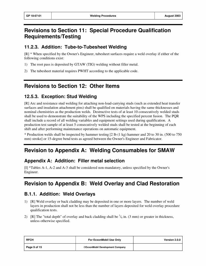
GP 18-07-01 Welding Procedures August 2003
RFCH For ExxonMobil Use Only Version 2.0.0
Page 9 of 15 ExxonMobil Development Company
Revisions to Section 11: Special Procedure Qualification Requirements/Testing
11.2.3. Addition: Tube-to-Tubesheet Welding
[R] * When specified by the Owner's Engineer, tubesheet surfaces require a weld overlay if either of the following conditions exist:
1) The root pass is deposited by GTAW (TIG) welding without filler metal.
2) The tubesheet material requires PWHT according to the applicable code.
Revisions to Section 12: Other Items
12.5.3. Exception: Stud Welding
[R] Arc and resistance stud welding for attaching non-load-carrying studs (such as extended heat transfer
surfaces and insulation attachment pins) shall be qualified on materials having the same thicknesses and nominal chemistries as the production welds. Destructive tests of at least 10 consecutively welded studs
shall be used to demonstrate the suitability of the WPS including the specified percent fusion. The PQR
shall include a record of all welding variables and equipment settings used during qualification. A
production test sample of at least 5 consecutively welded studs shall be tested at the beginning of each
shift and after performing maintenance operations on automatic equipment.
* Production welds shall be inspected by hammer testing [2 lb (1 kg) hammer and 20 to 30 in. (500 to 750
mm) stroke] or 15-degree bend tests as agreed between the Owner's Engineer and Fabricator.
Revision to Appendix A: Welding Consumables for SMAW
Appendix A: Addition: Filler metal selection
[I] *Tables A-1, A-2 and A-3 shall be considered non-mandatory, unless specified by the Owner's
Engineer.
Revision to Appendix B: Weld Overlay and Clad Restoration
B.1.1. Addition: Weld Overlays
1) [R] Weld overlay or back cladding may be deposited in one or more layers. The number of weld
layers in production shall not be less than the number of layers deposited for weld overlay procedure
qualification tests.
2) [R] The "total depth" of overlay and back cladding shall be 1/8 in. (3 mm) or greater in thickness,
unless otherwise specified.

GP 18-07-01 Welding Procedures August 2003
RFCH For ExxonMobil Use Only Version 2.0.0
Page 10 of 15 ExxonMobil Development Company
3) * [R] The "effective depth" of overlay and back cladding shall be the uppermost 1/16 in. (1.5 mm) of
the top layer as a minimum, unless otherwise specified. This material shall meet the specified
chemical composition where chemical analysis of the production overlay or back cladding is required.
4) [R] If multiple-layer overlay or back cladding is required to meet the specified chemistry, and
subsequent machining or grinding is necessary to satisfy dimensional requirements, the final
machined or ground surface shall retain the specified effective depth. Examples include machining of
gasket grooves in flanges and tubesheets, grinding of heat exchanger shell inside diameter to permit insertion of tube bundle.
5) [R] Weld overlay thickness shall be verified by actual measurement of the exposed edge at weld joint preparations. Questions regarding overlay thickness shall be resolved by ultrasonic thickness
measurements if necessary.
B.1.3. Addition: PQR Chemical Analysis
[R] The chemical composition at the "effective depth" of the overlay or back cladding shall be reported
for welding procedure qualification tests.
B.1.4. Addition: Production Chemical Analysis
[R] *Alternatively, the chemical composition at the "effective depth" of the overlay or back cladding
shall be reported for production welding, when specified by the Owner's Engineer. The acceptance requirements for production overlay and back cladding are found for the particular alloy(s) in B.3 through
B.6.
B.1.6. Addition: Extent of Chemistry and Ferrite Testing
1) [R] The number of samples for chemical analysis for all types of weld overlay and back cladding, and
number of ferrite measurements for austenitic stainless steel deposits, shall be as specified below.Test samples shall be removed, or in situ tests shall be conducted, prior to final PWHT at locations
selected by the Inspector.
a) Automatic weld overlay: One sample or test from each girth section and equipment component
(such as head, tubesheet, connection, etc.), and each back clad seam, except as provided in Item
B.1.6.c.
b) Manual weld overlay: Two samples or tests from each girth section and equipment component (such as head, tubesheet, connection, etc.), and each back clad seam, except as provided in Item
B.1.6.c.
c) For back clad seams 24 in. (600 mm) in diameter, one sample for each 24 diametral-inch, or part thereof. The 24 diametral-inch measurement shall be cumulative for all back clad seams 24
in. (600 mm) diameter and smaller employing the same welding procedure, process, and filler
metal.
Example: One 20 in. manway and three 8 in. nozzles 44 diametral-inches; or one 500 mm
manway and three 200 mm nozzles 1100 mm diametral measurement. Therefore, two tests are
required.

GP 18-07-01 Welding Procedures August 2003
RFCH For ExxonMobil Use Only Version 2.0.0
Page 11 of 15 ExxonMobil Development Company
2) * [R] For repetitive manual and automatic weld overlay operations on components > 24 in. (600 mm)
diameter, two tests per welder per week may be substituted for the requirements of Item 1 above.
However there shall be no change in welding procedure, filler metal classification, batch number of submerged arc or electroslag flux, or welding position. Authorization shall be at the discretion of the
Inspector.
B.1.8. Exception: Liquid Penetrant Examination
1) [R] For multiple-layer weld overlay or back cladding, liquid penetrant examination shall be
performed on the first layer as follows:
Automatic welding 5 percent minimum
Manual welding 12 percent minimum.
Examination methods and acceptance standards shall be in accordance with ASME SEC VIII D1 MA
APP 8. Any unacceptable indications shall be cause for liquid penetrant examination of the entire
surface of the overlay or back cladding.
2) * [R] Unless otherwise specified by the Owner's Engineer, the final surface of weld overlays, back
cladding, and welds joining attachments to weld overlays or integral cladding shall be 100 percent liquid penetrant examined with a water soluble penetrant following hydrostatic testing. However, for
heat exchangers, 100 percent liquid penetrant examination may be performed prior to hydrostatic
testing.
Examination and acceptance standards shall be as per ASME SEC VIII D1 MA APP 8.
Defective areas shall be repaired and reexamined.
B.2.1. Addition: Back Cladding
[I] Prior to backcladding butt joints, the weld groove in the backing material shall be filled approximately flush with, but not more than
1/16 in. (1.6 mm) below the weld overlay fusion line or the clad bond line
adjacent to the weld groove prior to back cladding. Care shall be taken to avoid cross-contaminating the
cladding and backing material weld metal. Any suspected areas of cross-contamination shall be etched
with either a nitric acid or copper sulfate solution to confirm the integrity of the clad surface.
B.3.2. Addition: Chemical Composition of Austenitic Stainless Steels
[R] The content of individual elements reported in the chemical analysis shall be within the range
specified in Table B-2, except for the following:
1) For low-carbon austenitic stainless steel deposits (e.g., 308L, 316L), the carbon content shall not exceed 0.04 percent.
2) For austenitic stainless steel deposits containing Cb (Nb) (e.g., Type 347 or Type 309Cb), the Cb (Nb) ratio (Cb/C) shall not exceed 16:1.
3) For Type 316 and 316L deposits the Mo content shall not be less than 2.25 percent.
B.3.3. Addition: Ferrite Testing of Austenitic Stainless Steels
[R] The austenitic stainless steel ferrite number shall be as follows:

GP 18-07-01 Welding Procedures August 2003
RFCH For ExxonMobil Use Only Version 2.0.0
Page 12 of 15 ExxonMobil Development Company
1) The ferrite content of the first layer and top layer, as described in Table B-1, of the following overlay
and back cladding materials shall be in the specified ferrite number (FN) range:
a) For Type 304, 304L, 316, 316L and 317L the FN range shall be 4–10.
b) For Type 347 the FN range shall be 5-11.
2) The ferrite content shall be determined by one of the following:
a) The actual, as-deposited chemical composition and the WRC-1988 or the DeLong (FN) Diagram
for Stainless Steel Weld Metal (ASME SEC II C SFA-5.9, Figures A1 and A3), or
b) Magnetic instrument as listed in AWS A4.2M/A4.2.
B.3.5. Exception: Calibration of Magnetic Ferrite Testing Gauges
1) [R] Magnetic gauges shall be calibrated and certified per AWS A4.2M/A4.2. An annual calibration
certification shall be available to the Inspector. Prior to use in production, instrument calibration shall
be verified on at least two standards (calibration test blocks) with a minimum ferrite spread of 5 FN. At least one of these standards shall have a FN of 4–10.
2) These standards shall be one of the following:
a) Primary or secondary weld metal standards described in AWS A4.2M/A4.2
b) Samples with certified chemical analyses referenced to the WRC-1988 (FN) Diagram or the
DeLong(FN) Diagram
c) Samples with ferrite content measured by metallographic techniques
B.5.2. Addition: Ferricyanide Testing of Ni-Cu (Alloy 400) and Cu-Ni Alloys
1) [R] Ferricyanide testing is required for all Nickel-copper [Alloy 400 (Monel), 67 Ni-30 Cu] and
copper-nickel (70 Cu-30 Ni, 90 Cu-10 Ni) alloy overlays and back cladding.
2) Ferricyanide tests shall be performed on 100 percent of finished nickel-copper or copper-nickel overlays and back cladding deposits. The results shall not indicate the presence of free iron.
The test procedure shall be as follows:
a) The surface to be examined shall be prepared by a method that does not cause contamination by
free iron. A solvent or detergent solution shall remove oil, grease and dirt. A pickling solution
may be used to remove oxides. The surface shall be thoroughly rinsed after pickling or detergent cleaning, using distilled or de-ionized water. If mechanical surface preparation is required, new
emery paper or grinding wheels, and non-ferritic buffing wheels and brushes shall be used.
b) Composition of the test solution shall be as follows:
i) 90 percent by volume potassium ferricyanide (4 percent solution)
ii) 10 percent by volume solution consisting of 1 part concentrated hydrochloric acid (36-38
percent by weight HCl) and 9 parts distilled water
c) Fresh test solution shall be prepared immediately before application.
d) The testing solution's reaction shall be checked on samples of nickel-copper or copper-nickel and carbon steel. A blue color should appear immediately on carbon steel. No color should appear
on nickel-copper or copper-nickel within 10 minutes. If color does appear, the solution is too
acidic, and new solution shall be formulated.

GP 18-07-01 Welding Procedures August 2003
RFCH For ExxonMobil Use Only Version 2.0.0
Page 13 of 15 ExxonMobil Development Company
e) Solution shall be applied to the tested surface by spraying (using an atomizer) or drop-by-drop
(using an eyedropper). Appearance of a definite blue color within two minutes indicates the
presence of free iron. A light blue tint shall be considered insignificant.
f) Questions regarding determination of iron content based on the degree of blueness shall be
resolved by spot chemical analysis. The iron content shall not exceed 6 percent.
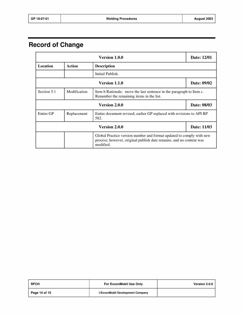
GP 18-07-01 Welding Procedures August 2003
RFCH For ExxonMobil Use Only Version 2.0.0
Page 14 of 15 ExxonMobil Development Company
Record of Change
Version 1.0.0 Date: 12/01
Location Action Description
Initial Publish.
Version 1.1.0 Date: 09/02
Section 5.1 Modification Item b Rationale: move the last sentence in the paragraph to Item c.
Renumber the remaining items in the list.
Version 2.0.0 Date: 08/03
Entire GP Replacement Entire document revised; earlier GP replaced with revisions to API RP
582.
Version 2.0.0 Date: 11/03
Global Practice version number and format updated to comply with new
process; however, original publish date remains, and no content was modified.

GP 18-07-01 Welding Procedures August 2003
RFCH For ExxonMobil Use Only Version 2.0.0
Page 15 of 15 ExxonMobil Development Company
Attachment: Purpose Codes Definitions
Code Description
C Assigned to paragraphs containing specifications whose primary purpose is reduced costs.
Reduced cost in this context refers to initial investment cost and does not include Life-Cycle
cost considerations. Life-Cycle cost considerations are captured under reliability,
maintainability, or operability purpose codes.
E Assigned to paragraphs containing specifications whose primary purpose is driven by
environmental considerations. Environmental considerations typically include specifications
intended to protect against emissions/leakage to the air, water, and/or soil. Deviations from the specifications contained in such paragraphs require formal review and approval according to
local environmental policy.
I Assigned to paragraphs that provide only clarifying information such as Scope statements,
definitions of terms, etc.
M Assigned to paragraphs containing specifications whose primary purpose is to provide for
maintainability of equipment or systems. Maintainability provisions are those that facilitate the
performance of maintenance on equipment/systems either during downtimes or during on-
stream operations.
O Assigned to paragraphs containing specifications whose primary purpose is to assure
operability of equipment or systems. Operability is the ability of the equipment/system to
perform satisfactorily even though conditions are off-design, such as during startups, process swings, subcomponent malfunction, etc.
R Assigned to paragraphs containing specifications whose primary purpose is to improve or
assure the reliability of equipment or systems. Reliability is a measure of the ability of
equipment/systems to operate without malfunction or failure between planned maintenance interventions.
S Assigned to paragraphs containing specifications whose primary purpose is avoidance of
personnel or operational safety incidents. Any deviation from the specifications contained in
such designated paragraphs requires formal review and approval according to local safety policy.
Personnel Safety: Refers to the avoidance of recordable personnel injuries; i.e., burns, cuts,
abrasions, inhalation, or exposure to dangerous substances, etc., that could result in medical treatment, restricted work, lost-time incidents, or
fatalities.
Operational
Safety:
Refers to the prevention and control of process releases, fires, explosions,
etc.
GP 18-10-01 Additional Requirements for Materials February 2008
Refining/Chemicals For Company Use Only Version 4.0.0
Page 1 of 26 ExxonMobil Development Company
Copyright Waiver ExxonMobil Development Company and ExxonMobil Pipeline Company hereby license the use of ExxonMobil Engineering Practices System (EMEPS) Global Practices (GPs) for use by any ExxonMobil division, subsidiary, or more-than-50%-owned affiliate. The GPs may be downloaded and modified as necessary for project and affiliate use. Written permission from ExxonMobil Development Company or ExxonMobil Pipeline Company is not required. However, any modified GPs must be renumbered to a project-specific or affiliate-specific number to distinguish them from the GPs on the EMEPS web site. ExxonMobil operated joint ventures may utilize GPs to create project-specific or location-specific specifications. It is the responsibility of individual affiliate or joint venture to ensure that the use of GPs and their derivatives is limited to joint venture related business and not disclosed or used outside the JV without appropriate EM management approval.
Additional Requirements for Materials
GP 18-10-01
Scope
[I] This Global Practice (GP) covers special materials requirements relating to the fabrication of
equipment in the areas of hardness testing, carbon steel chemistry requirements, hydrostatic and wash
water quality, impact testing, and protection of equipment.

GP 18-10-01 Additional Requirements for Materials February 2008
RFCH For Company Use Only Version 4.0.0
Page 2 of 26 ExxonMobil Development Company
Table of Contents
Table of Tables .............................................................................................................. 4
1. Required References ............................................................................................ 5
1.1. Global Practices–ExxonMobil Engineering Practices ................................... 5
1.2. API–American Petroleum Institute................................................................ 5
1.3. ASME–American Society of Mechanical Engineers ..................................... 5
1.4. ASTM–American Society for Testing and Materials ..................................... 5
1.5. BSI–British Standards Institution .................................................................. 6
1.6. NACE–National Association of Corrosion Engineers.................................... 6
1.7. SNCT and AFIAP ......................................................................................... 6
1.8. STOOMWEZEN (Netherlands)..................................................................... 6
2. Definitions.............................................................................................................. 6
3. Portable Hardness Testing for Fabrication......................................................... 8
3.1. Personnel and Procedure Qualification ........................................................ 8
3.2. Testing Equipment........................................................................................ 8
3.3. Testing Procedure ........................................................................................ 9
3.4. General Requirements and Acceptable Hardness Values............................ 9
3.5. Pressure Vessels (Including Heat Exchangers), Pressure Storage Spheres and Storage Tanks ..................................................................................... 10
3.6. Piping ......................................................................................................... 11
3.7. Remedial Measures and Documentation.................................................... 12
4. Carbon Steel Chemistry Control ........................................................................ 13
5. Hydrostatic Test and Wash Water Quality ........................................................ 14
6. Impact Testing Requirements for Materials...................................................... 15
6.1. Summary of Exceptions and Additions to Impact Requirements ................ 16
6.2. Impact Requirements for Machinery........................................................... 16
7. Materials Requirements for Wet H2S and HF Service ...................................... 17
8. Additional Requirements for Cr-Mo Steels ....................................................... 19
9. Protection of Stainless Steel during Shop Handling, Storage, Shipping, and Field Construction............................................................................................... 19
GP 18-10-01 Additional Requirements for Materials February 2008
RFCH For Company Use Only Version 4.0.0
Page 3 of 26 ExxonMobil Development Company
10. Preservation and Protection of Equipment during Shipping and Construction19
Record of Change ....................................................................................................... 20
Attachment: Purpose Code Definitions.................................................................... 26

GP 18-10-01 Additional Requirements for Materials February 2008
RFCH For Company Use Only Version 4.0.0
Page 4 of 26 ExxonMobil Development Company
Table of Tables
Table 1: Acceptable Hardness Testers....................................................................... 8
Table 2: Material Hardness Limits ............................................................................ 10
Table 3: Material Hardness Requirements for Welded Joints of Pressure Vessel, Storage Spheres and Tanks...................................................................... 11
Table 4: Material Hardness Requirements for Welded Piping Components......... 12
Table 5: Supplementary Carbon Steel Chemistry Requirements........................... 13
Table 6: Impact Requirements .................................................................................. 17

GP 18-10-01 Additional Requirements for Materials February 2008
RFCH For Company Use Only Version 4.0.0
Page 5 of 26 ExxonMobil Development Company
1. Required References
This section lists the Practices, codes, standards, specifications, and publications that shall be used with this document. Unless otherwise specified herein, use the latest edition.
1.1. Global Practices–ExxonMobil Engineering Practices
GP 03-15-01 Pressure Relief Valves
GP 09-04-01 Atmospheric Storage Tanks
GP 09-06-01 Refrigerated Storage Tanks
1.2. API–American Petroleum Institute
API 579-1 Fitness-for-Service
API RP 941 Steels for Hydrogen Service at Elevated Temperatures and Pressures in Petroleum Refineries and Petrochemical Plants
API STD 661 Air-Cooled Heat Exchangers for General Refinery Services
1.3. ASME–American Society of Mechanical Engineers
ASME B31.3 Process Piping
ASME SEC II A BPVC Section II A - Materials Part A - Ferrous Material Specifications
ASME SEC II C BPVC Section II C - Materials Part C - Specifications for Welding Rods, Electrodes, and Filler Metals
ASME SEC VIII D1 BPVC Section VIII - Rules for Construction of Pressure Vessels -
Division 1
ASME SEC VIII D2 BPVC Section VIII - Rules for Construction of Pressure Vessels - Division 2 Alternative Rules
ASME SEC IX BPVC Section IX - Qualification Standard for Welding and Brazing
Procedures, Welders, Brazers, and Welding and Brazing Operators
1.4. ASTM–American Society for Testing and Materials
ASTM A 833 Standard Practice for Indentation Hardness of Metallic Materials by Comparison Hardness Testers
ASTM A 956 Standard Test Method for Leeb Hardness Testing of Steel Products

GP 18-10-01 Additional Requirements for Materials February 2008
RFCH For Company Use Only Version 4.0.0
Page 6 of 26 ExxonMobil Development Company
1.5. BSI–British Standards Institution
BSI BS EN 1011-2 Welding - Recommendations for Welding of Metallic Materials - Part 2:
Arc Welding of Ferritic Steels
BSI BS EN 13445 Unfired Pressure Vessels
BSI PD 5500 Specification for Unfired Fusion Welded Pressure Vessels
1.6. NACE–National Association of Corrosion Engineers
NACE MR0103 Materials Resistant to Sulfide Stress Cracking in Corrosive Petroleum
Refining Environments
NACE MR0175/ISO 15156
Petroleum and Natural Gas Industries Materials for Use in H2S-Containing Environments in Oil and Gas Production
NACE TM0284 Evaluation of Pipeline and Pressure Vessel Steels for Resistance to
Hydrogen-Induced Cracking
1.7. SNCT and AFIAP
COD AP French Code for the Manufacture of Unfired Pressure Vessels
1.8. STOOMWEZEN (Netherlands)
STOOMWEZEN Rules for Equipment Under Pressure
2. Definitions
Term [I] Description
Critical Exposure
Temperature (CET)
[*] Defined as the lowest metal temperature derived from either the
operating or atmospheric conditions. The CET may be a single temperature at an operating pressure or an envelope of temperatures and
pressures. The CET is determined for different types of equipment
including pressure vessels, piping, and machinery as defined herein.
CET for Machinery The CET for machinery pressure containing components to be supplied
by the Owner's Engineer.

GP 18-10-01 Additional Requirements for Materials February 2008
RFCH For Company Use Only Version 4.0.0
Page 7 of 26 ExxonMobil Development Company
Term [I] Description
CET for Piping The CET for systems constructed to ASME B31.3 is defined as the lowest metal temperature at which a component will be subject to either
30 percent of the maximum allowable working pressure (MAWP) at
ambient temperature or a combined total longitudinal stress due to
pressure, weight effects, and displacement strains that do not exceed 55.2 MPa (8 ksi). The CET for piping is determined from the
anticipated process and atmospheric conditions.
The CET for pressure vessels is determined from the anticipated process and atmospheric conditions.
The CET is defined as the lowest metal temperature at which a
component will be subjected to a general primary membrane tensile stress greater than 55.2 MPa (8 ksi). The CET may also be defined
according to the following options:
1. The minimum metal temperature at which a component could be
subjected to a pressure greater than 40 percent of the design pressure for vessels constructed to ASME SEC VIII D1.
2. The minimum metal temperature at which a component could be
subjected to a pressure greater than 35 percent of the design
pressure for vessels constructed to ASME SEC VIII D1, with a 3.5
safety factor as recognized in the 1999 addenda.
3. The minimum metal temperature at which a component could be
subjected to a pressure greater than 30 percent of the design pressure for vessels constructed to ASME SEC VIII D2.
CET for Pressure
Vessels (including
heat exchangers and
pressure storage
spheres)
4. For pressure vessels designed to a higher allowable stress than that
permitted in these codes, the CET may be taken as the lowest metal
temperature at which the vessel will be subjected to a pressure no greater than 25 percent of the design pressure or a membrane stress
of no greater than 55.2 MPa (8 ksi).
Hardness Test A single hardness reading in the weld metal, base metal, or HAZ.
Heat Affected Zone
(HAZ)
The zone of the base metal affected by the heat input of welding.
Hydrogen Service Equipment is in hydrogen service when the design temperature is greater
than the carbon steel (CS) curve in API RP 941 for the given hydrogen
partial pressure.
Inspector As used in this GP, refers to the Owner's Representative.

GP 18-10-01 Additional Requirements for Materials February 2008
RFCH For Company Use Only Version 4.0.0
Page 8 of 26 ExxonMobil Development Company
Term [I] Description
A steel that meets one of the following descriptions:
1. Martensitic or ferritic chromium stainless steels containing more than 10 percent chromium (typically AISI 400 series).
2. Austenitic chromium-nickel stainless steels containing more than
16 percent chromium and more than 6 percent nickel (typically AISI 300 series). This also includes the super austenitic stainless
steels (with 6 percent Mo) and the alloys with nominally 20 percent
Cr and 35 percent Ni such as Incoloy 825 or Alloy 20.
Stainless Steel
3. Duplex ferritic-austenitic stainless steels containing approximately 15 to 30 percent chromium and 2 to 8 percent nickel (typically the
2205 and 2507 alloys).
Wet H2S Service Equipment is in wet H2S service when any one of the conditions in
NACE MR0175/ISO 15156 is met.
Wet H2S Service
Alternate
Downstream Case
Equipment is in wet H2S service when any one of the conditions in
NACE MR0103, Paragraph 1.3.5.1 is met.
3. Portable Hardness Testing for Fabrication
3.1. Personnel and Procedure Qualification
[R] Personnel performing hardness testing shall demonstrate their capabilities to the satisfaction of the
Inspector. Qualification of the hardness testing personnel, including training and experience, shall be made available to the Inspector.
3.2. Testing Equipment
[A] [R] A list of acceptable hardness testers is shown in Table 1. The Owner's Engineer shall approve
any hardness tester not listed in Table 1.
Table 1: Acceptable Hardness Testers
Brinell Type Hardness Testers Dynamic/Rebound Type
Hardness Tester
Telebrineller Newage Calibrated Pin Tester EQUOTIP
Teleweld, Inc. Newage Ind., Inc. EQUOTIP Associates
416 North Park St. 2300 Maryland Rd. 140 Industry Drive
Streator, IL 61364 Willow Grove, PA 19090 Pittsburgh, PA 15275
Minibrineller L.C. Eitzen Brinell Meter

GP 18-10-01 Additional Requirements for Materials February 2008
RFCH For Company Use Only Version 4.0.0
Page 9 of 26 ExxonMobil Development Company
Electromechanical Components L.C. Eitzen Co. Inc.
P.O. Box 159 P.O. Box 1210
Gillette, NJ 07933 Glenwood Springs, CO 81601
3.3. Testing Procedure
1) [R] Testing procedures using the Brinell Type Hardness Tester shall be as follows:
a) Brinell hardness test methods shall be in accordance with ASTM A 833 and Manufacturer
recommendations.
b) Hardness tests shall be conducted in the center of the weld and in the HAZ and adjacent base
metal, when required.
c) The diameter of the indention ball shall not be smaller than 7 mm and not larger than 10 mm.
d) If a hardness reference bar is used, the bar hardness shall be within 12.5 percent of the maximum
hardness required for the specific material.
e) The surface to be hardness tested shall be ground to ensure that the edge of the impression will be
clearly defined to permit measurement of the diameter to within 0.02 mm.
f) Grinding shall be conducted in such a manner that overheating of the material is prevented.
g) Adjacent readings shall be at least 0.25 in. (6.4 mm) apart, edge to edge.
h) When hardness testing of the HAZ is required, the weld cap shall be ground so that the indention
ball can be placed in the center of the HAZ. This hardness test shall represent a composite of
weld metal, HAZ, and base metal.
2) [R] Testing procedures using the Dynamic/Rebound Type Hardness Tester shall be as follows:
a) The hardness test method shall be in accordance with ASTM A 956 and Manufacturer recommendations.
b) Five hardness tests shall be conducted in the specific zone of the weld joint. The five readings
and the average shall be reported. If there is a variation in readings greater than 15 percent,
testing with a Brinell-type hardness tester is required.
c) The hardness test instrument shall be calibrated in the same position as intended for production
testing.
d) The minimum wall thickness shall be 0.35 in. (9 mm).
e) The surface of the component being tested must be prepared with a fine file or small grinder to the surface finish required in ASTM A 956 or 32 micro-inches, whichever is smoother.
3.4. General Requirements and Acceptable Hardness Values
1) [R] The hardness of hot-formed bends and of the base metal, weld metal, and the related HAZ of all welds shall not exceed the limits given in Table 2.
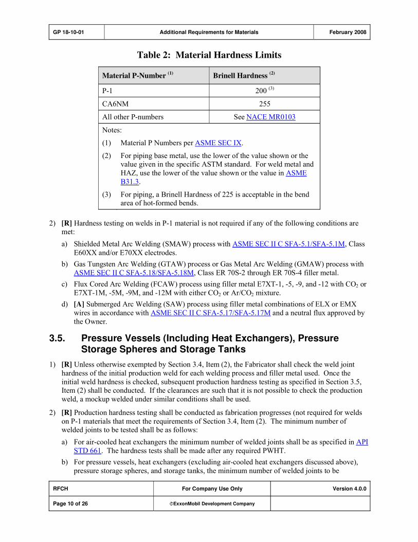
GP 18-10-01 Additional Requirements for Materials February 2008
RFCH For Company Use Only Version 4.0.0
Page 10 of 26 ExxonMobil Development Company
Table 2: Material Hardness Limits
Material P-Number (1)
Brinell Hardness (2)
P-1 200 (3)
CA6NM 255
All other P-numbers See NACE MR0103
Notes:
(1) Material P Numbers per ASME SEC IX.
(2) For piping base metal, use the lower of the value shown or the value given in the specific ASTM standard. For weld metal and
HAZ, use the lower of the value shown or the value in ASME
B31.3.
(3) For piping, a Brinell Hardness of 225 is acceptable in the bend area of hot-formed bends.
2) [R] Hardness testing on welds in P-1 material is not required if any of the following conditions are met:
a) Shielded Metal Arc Welding (SMAW) process with ASME SEC II C SFA-5.1/SFA-5.1M, Class
E60XX and/or E70XX electrodes.
b) Gas Tungsten Arc Welding (GTAW) process or Gas Metal Arc Welding (GMAW) process with
ASME SEC II C SFA-5.18/SFA-5.18M, Class ER 70S-2 through ER 70S-4 filler metal.
c) Flux Cored Arc Welding (FCAW) process using filler metal E7XT-1, -5, -9, and -12 with CO2 or
E7XT-1M, -5M, -9M, and -12M with either CO2 or Ar/CO2 mixture.
d) [A] Submerged Arc Welding (SAW) process using filler metal combinations of ELX or EMX
wires in accordance with ASME SEC II C SFA-5.17/SFA-5.17M and a neutral flux approved by
the Owner.
3.5. Pressure Vessels (Including Heat Exchangers), Pressure Storage Spheres and Storage Tanks
1) [R] Unless otherwise exempted by Section 3.4, Item (2), the Fabricator shall check the weld joint
hardness of the initial production weld for each welding process and filler metal used. Once the
initial weld hardness is checked, subsequent production hardness testing as specified in Section 3.5, Item (2) shall be conducted. If the clearances are such that it is not possible to check the production
weld, a mockup welded under similar conditions shall be used.
2) [R] Production hardness testing shall be conducted as fabrication progresses (not required for welds
on P-1 materials that meet the requirements of Section 3.4, Item (2). The minimum number of welded joints to be tested shall be as follows:
a) For air-cooled heat exchangers the minimum number of welded joints shall be as specified in API
STD 661. The hardness tests shall be made after any required PWHT.
b) For pressure vessels, heat exchangers (excluding air-cooled heat exchangers discussed above),
pressure storage spheres, and storage tanks, the minimum number of welded joints to be
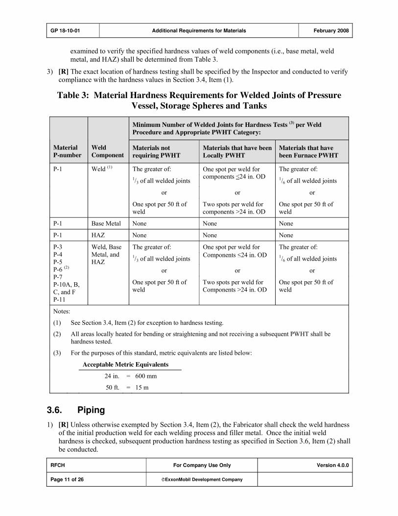
GP 18-10-01 Additional Requirements for Materials February 2008
RFCH For Company Use Only Version 4.0.0
Page 11 of 26 ExxonMobil Development Company
examined to verify the specified hardness values of weld components (i.e., base metal, weld
metal, and HAZ) shall be determined from Table 3.
3) [R] The exact location of hardness testing shall be specified by the Inspector and conducted to verify compliance with the hardness values in Section 3.4, Item (1).
Table 3: Material Hardness Requirements for Welded Joints of Pressure
Vessel, Storage Spheres and Tanks
Minimum Number of Welded Joints for Hardness Tests (3) per Weld
Procedure and Appropriate PWHT Category:
Material
P-number
Weld
Component Materials not
requiring PWHT
Materials that have been
Locally PWHT
Materials that have
been Furnace PWHT
The greater of: The greater of:
1/3 of all welded joints
One spot per weld for components 24 in. OD 1/6 of all welded joints
or or or
P-1 Weld (1)
One spot per 50 ft of
weld
Two spots per weld for
components >24 in. OD
One spot per 50 ft of
weld
P-1 Base Metal None None None
P-1 HAZ None None None
The greater of: The greater of:
1/3 of all welded joints
One spot per weld for
Components 24 in. OD 1/6 of all welded joints
or or or
P-3
P-4
P-5
P-6 (2)
P-7
P-10A, B,
C, and F
P-11
Weld, Base
Metal, and
HAZ
One spot per 50 ft of
weld
Two spots per weld for
Components >24 in. OD
One spot per 50 ft of
weld
Notes:
(1) See Section 3.4, Item (2) for exception to hardness testing.
(2) All areas locally heated for bending or straightening and not receiving a subsequent PWHT shall be
hardness tested.
(3) For the purposes of this standard, metric equivalents are listed below:
Acceptable Metric Equivalents
24 in. = 600 mm
50 ft. = 15 m
3.6. Piping
1) [R] Unless otherwise exempted by Section 3.4, Item (2), the Fabricator shall check the weld hardness of the initial production weld for each welding process and filler metal. Once the initial weld
hardness is checked, subsequent production hardness testing as specified in Section 3.6, Item (2) shall
be conducted.

GP 18-10-01 Additional Requirements for Materials February 2008
RFCH For Company Use Only Version 4.0.0
Page 12 of 26 ExxonMobil Development Company
2) [R] Production hardness testing shall be conducted as fabrication progresses. The minimum number
of welded joints to be examined to verify the specified hardness values of weld components (i.e., base
metal, weld metal, and HAZ) shall be determined from Table 4.
3) [R] The exact location of hardness testing shall be specified by the Inspector and conducted in the
Inspector's presence to verify compliance with the hardness values in Section 3.4, Item (1).
4) [*] [R] The minimum number of hot-formed bends to be examined, and the extent of the
examination, shall be specified by the Owner for P-1 material.
3.7. Remedial Measures and Documentation
1) [R] When hardness tests exceed the maximum values, the Owner shall be notified before Manufacturer or Fabricator takes corrective action.
2) [R] Additional hardness tests (progressive examination) shall be performed for each weld component found to exceed the specified hardness. The Inspector shall select like components from two
additional welded joints for such testing.
3) [A] A hardness test report shall be prepared by Manufacturer or Fabricator and submitted to the Owner.
4) The hardness test report shall indicate the following:
a) Type of hardness tester and its last calibration date
b) Personnel conducting hardness tests
c) Type of material
d) Test location
e) Reading of each point tested
Table 4: Material Hardness Requirements for Welded Piping Components
Minimum Number of Welded Joints for Hardness Tests, per Appropriate
PWHT Category:
Material
P-number
Weld
Component Materials not
requiring PWHT
Materials that have been
Locally PWHT
Materials that have
been Furnace PWHT
P-1 Weld (3) 1/3 of all welded joints 1/6 of all welded joints 3 welded joints per
furnace charge
P-1 Base Metal As required (1) None None
P-1 HAZ None None None
P-3
P-4
P-5
P-6 (2) P-7
P-10A, B,
C, and F
P-11
Weld, Base
Metal, and
HAZ
1/3 of all welded joints 100 percent of all welded
joints
10 percent of the welded
joints per furnace charge
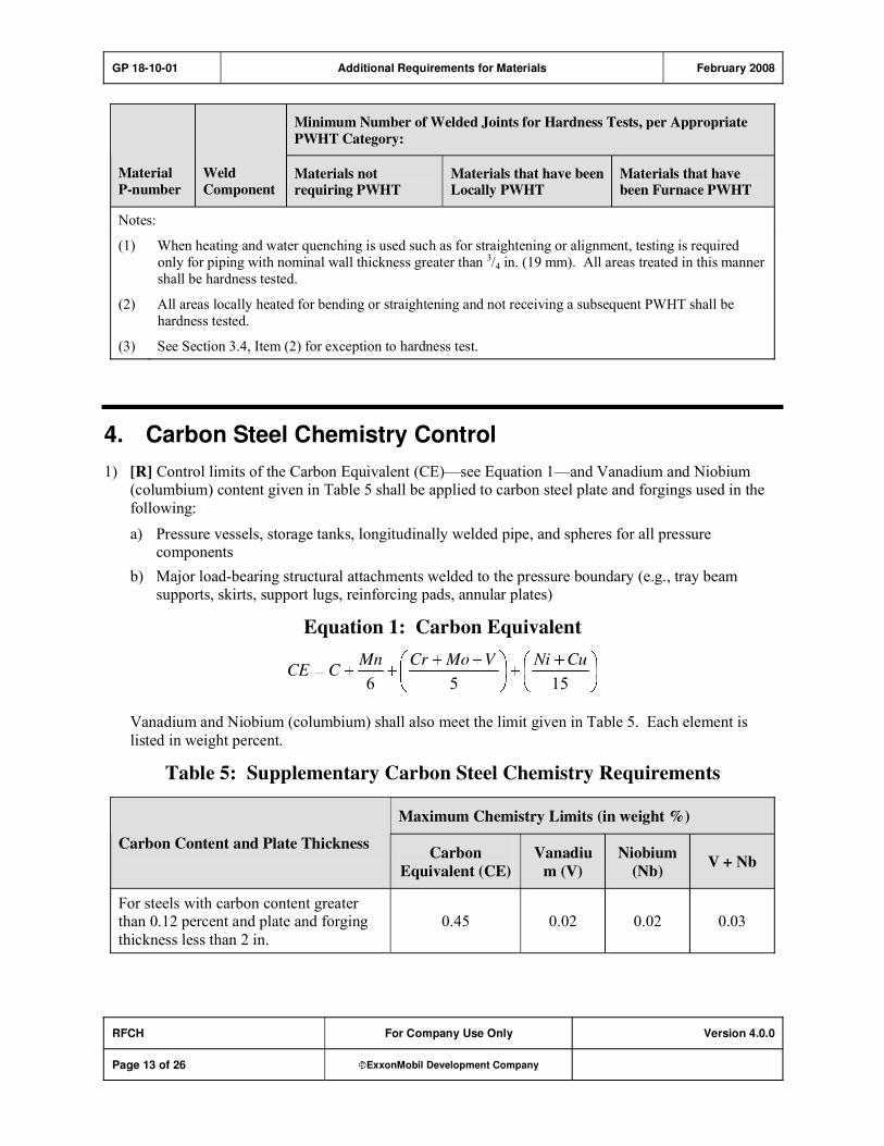
GP 18-10-01 Additional Requirements for Materials February 2008
RFCH For Company Use Only Version 4.0.0
Page 13 of 26 ExxonMobil Development Company
Minimum Number of Welded Joints for Hardness Tests, per Appropriate
PWHT Category:
Material
P-number
Weld
Component Materials not requiring PWHT
Materials that have been Locally PWHT
Materials that have been Furnace PWHT
Notes:
(1) When heating and water quenching is used such as for straightening or alignment, testing is required
only for piping with nominal wall thickness greater than 3/4 in. (19 mm). All areas treated in this manner
shall be hardness tested.
(2) All areas locally heated for bending or straightening and not receiving a subsequent PWHT shall be
hardness tested.
(3) See Section 3.4, Item (2) for exception to hardness test.
4. Carbon Steel Chemistry Control
1) [R] Control limits of the Carbon Equivalent (CE)�see Equation 1�and Vanadium and Niobium (columbium) content given in Table 5 shall be applied to carbon steel plate and forgings used in the
following:
a) Pressure vessels, storage tanks, longitudinally welded pipe, and spheres for all pressure components
b) Major load-bearing structural attachments welded to the pressure boundary (e.g., tray beam supports, skirts, support lugs, reinforcing pads, annular plates)
Equation 1: Carbon Equivalent
1556
CuNiVMoCrMnCCE
Vanadium and Niobium (columbium) shall also meet the limit given in Table 5. Each element is
listed in weight percent.
Table 5: Supplementary Carbon Steel Chemistry Requirements
Maximum Chemistry Limits (in weight %)
Carbon Content and Plate Thickness Carbon
Equivalent (CE)
Vanadiu
m (V)
Niobium
(Nb)V + Nb
For steels with carbon content greater than 0.12 percent and plate and forging
thickness less than 2 in.
0.45 0.02 0.02 0.03
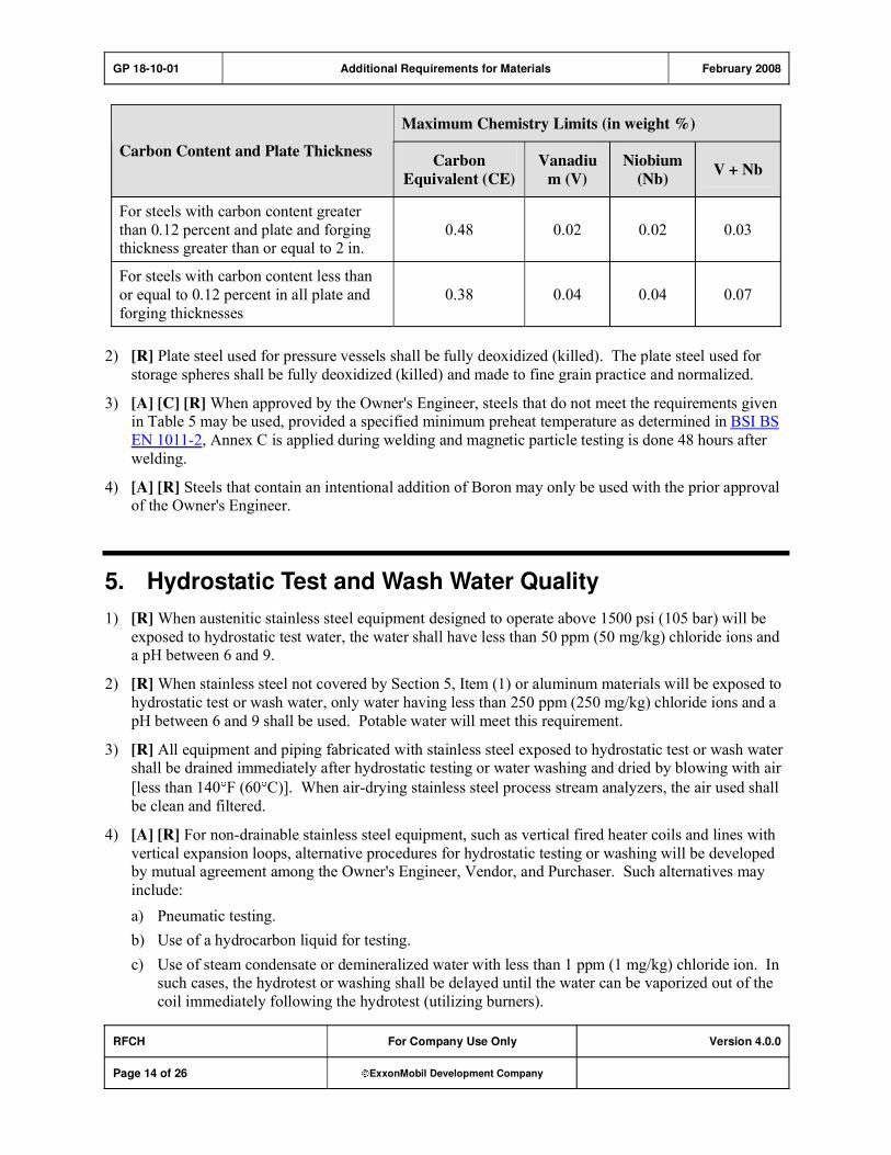
GP 18-10-01 Additional Requirements for Materials February 2008
RFCH For Company Use Only Version 4.0.0
Page 14 of 26 ExxonMobil Development Company
Maximum Chemistry Limits (in weight %)
Carbon Content and Plate Thickness Carbon
Equivalent (CE)
Vanadiu
m (V)
Niobium
(Nb)V + Nb
For steels with carbon content greater
than 0.12 percent and plate and forging thickness greater than or equal to 2 in.
0.48 0.02 0.02 0.03
For steels with carbon content less than
or equal to 0.12 percent in all plate and
forging thicknesses
0.38 0.04 0.04 0.07
2) [R] Plate steel used for pressure vessels shall be fully deoxidized (killed). The plate steel used for
storage spheres shall be fully deoxidized (killed) and made to fine grain practice and normalized.
3) [A] [C] [R] When approved by the Owner's Engineer, steels that do not meet the requirements given in Table 5 may be used, provided a specified minimum preheat temperature as determined in BSI BS
EN 1011-2, Annex C is applied during welding and magnetic particle testing is done 48 hours after
welding.
4) [A] [R] Steels that contain an intentional addition of Boron may only be used with the prior approval of the Owner's Engineer.
5. Hydrostatic Test and Wash Water Quality
1) [R] When austenitic stainless steel equipment designed to operate above 1500 psi (105 bar) will be
exposed to hydrostatic test water, the water shall have less than 50 ppm (50 mg/kg) chloride ions and a pH between 6 and 9.
2) [R] When stainless steel not covered by Section 5, Item (1) or aluminum materials will be exposed to
hydrostatic test or wash water, only water having less than 250 ppm (250 mg/kg) chloride ions and a
pH between 6 and 9 shall be used. Potable water will meet this requirement.
3) [R] All equipment and piping fabricated with stainless steel exposed to hydrostatic test or wash water shall be drained immediately after hydrostatic testing or water washing and dried by blowing with air
[less than 140 F (60 C)]. When air-drying stainless steel process stream analyzers, the air used shall
be clean and filtered.
4) [A] [R] For non-drainable stainless steel equipment, such as vertical fired heater coils and lines with
vertical expansion loops, alternative procedures for hydrostatic testing or washing will be developed by mutual agreement among the Owner's Engineer, Vendor, and Purchaser. Such alternatives may
include:
a) Pneumatic testing.
b) Use of a hydrocarbon liquid for testing.
c) Use of steam condensate or demineralized water with less than 1 ppm (1 mg/kg) chloride ion. In such cases, the hydrotest or washing shall be delayed until the water can be vaporized out of the
coil immediately following the hydrotest (utilizing burners).

GP 18-10-01 Additional Requirements for Materials February 2008
RFCH For Company Use Only Version 4.0.0
Page 15 of 26 ExxonMobil Development Company
5) [R] If equipment or piping is subjected to extended hydrostatic test or wet lay-up conditions (greater
than 72 hours), the test water shall be treated with a biocide (to minimize the risk of microbiological
contamination) and a corrosion inhibitor, when necessary.
6) [A] [R] Salt or brackish water is permitted for hydrotesting of carbon steel piping and equipment,
provided the Contractor's test procedures are approved by the Owner's Engineer and that they include
the following:
a) Methods for isolating austenitic stainless steel piping and connected equipment from contact with salty water
b) Steps to be taken after testing to ensure complete removal of salty water from the system
c) Chemical treatment (e.g., inhibitors, oxygen scavengers) to mitigate corrosion if salt water will
remain for more than 5 days
7) [A] If the substitution of pneumatic testing for hydrostatic testing is approved by the Owner's
Engineer, pneumatic testing shall be performed at a temperature not less than 60 F (33 C) above the temperature at which impact requirements given in this GP are met by the material, but not greater
than 120 F (49 C) for all equipment and piping components where the wall thicknesses do not exceed 2 in. (50 mm). Procedures for testing at lower temperatures or greater wall thicknesses shall be
reviewed and approved by the Owner's Engineer.
6. Impact Testing Requirements for Materials
1) [S] [*] This Section covers impact testing requirements for pressure vessels, piping, and machinery. Impact requirements shall be based on the Critical Exposure Temperature (CET) established by the
Owner's Engineer. Impact requirements for atmospheric storage tanks and refrigerated storage tanks
are addressed in GP 09-04-01 and GP 09-06-01, respectively. Impact requirements for pressure relief valves are covered in GP 03-15-01.
2) [R] The following identify impact requirements for equipment and piping covered by this GP:
a) [A] For pressure vessels, including heat exchangers and pressure storage spheres, the impact requirements shall be as specified by one of the following codes with the exceptions and
additions as listed below:
i) ASME SEC VIII D1 or ASME SEC VIII D2
ii) BSI BS EN 13445
iii) BSI PD 5500
iv) COD AP
v) STOOMWEZEN
When one of these codes governs the design of the pressure vessel, the same code shall be followed for impact testing requirements. Other codes covering impact requirements may be
permitted provided they are reviewed and accepted by the Owner's Engineer.
b) For piping including piping components (e.g., valves, etc.), the impact requirements specified by ASME B31.3 shall be followed with the exceptions and additions listed in Section 6.1 of this GP.
c) For machinery equipment, this GP provides the impact requirements.

GP 18-10-01 Additional Requirements for Materials February 2008
RFCH For Company Use Only Version 4.0.0
Page 16 of 26 ExxonMobil Development Company
6.1. Summary of Exceptions and Additions to Impact Requirements
1) When using the ASME Code to define the impact requirements, the minimum design metal temperature (MDMT) shall be at least as low as the CET.
2) [R] Components of equipment to be pneumatically tested shall be normalized and manufactured to a
fine grain practice.
3) [R] Exemptions permitted by ASME SEC VIII D1 A UG, Paragraph UG-20 "Design Temperature," Item (f) are allowed except that Curve B materials are exempt to 1/2 in. (13 mm), not 1 in. (25 mm).
4) [A] [R] If the base metal is exempt from toughness testing, the weld metal shall have a toughness
equal to or greater than 20 ft-lbs (27 J) at 0 F (-18 C) or the CET, whichever is lower. The weld
metal toughness shall be certified by the manufacturer of the filler metal according to ASME SEC II
C, or when approved by the Owner's Engineer, shall be established by testing of the weld procedure
qualification test plate.
5) [A] [R] For CS vessels and piping, only filler metals classifications having minimum specified impact toughness levels at the lesser of 0°F or the CET, shall be used regardless whether the base
metal requires impact testing or not, unless approved by the Owner's Engineer.
6) When Charpy impact testing is required for base metals, the orientation of the test specimens shall be
as follows, unless otherwise specified by the applicable construction code:
a) Plate materials: Impact specimens shall be prepared with the base of the notch perpendicular to
the plate surface.
b) Cylindrical pressure vessels: Impact specimens shall have their long dimensions parallel to the
final direction of rolling (longitudinal specimens). Specimens with their long dimensions in the
transverse direction are also acceptable.
c) Spheres or hemispherical heads fabricated from segments: Impact specimens shall have their
long dimensions perpendicular to the final rolling direction (transverse specimens).
d) Pipe materials: Impact specimens shall be prepared with their long dimensions oriented in the
transverse direction.
i) The base of the notch shall be placed perpendicular to the pipe surface and located in the
weld (if longitudinally welded) barring constraints as follows:
ii) Geometric constraints: When longitudinally welded pipe cannot accommodate a transverse
impact specimen, a longitudinal specimen may be used with the root of the notch located in
weld metal.
e) Forgings: Test specimens shall be prepared in accordance with ASME SEC II A SA-350/SA-
350M.
f) Castings: Specimens shall be removed from a test block and prepared in accordance with the
relevant ASME materials specifications.
6.2. Impact Requirements for Machinery
1) [R] Pressure containing machinery components such as compressor and pump casings, including cast,
forged, or welded nozzles, shall meet the requirements in Table 6.
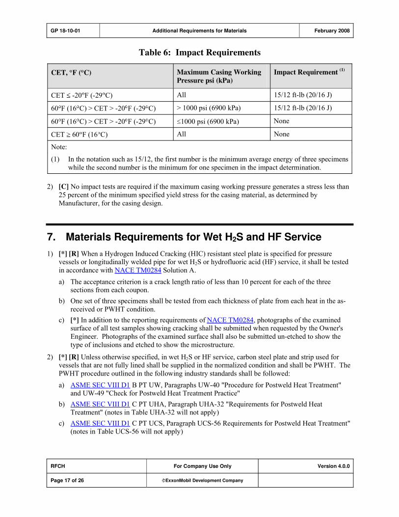
GP 18-10-01 Additional Requirements for Materials February 2008
RFCH For Company Use Only Version 4.0.0
Page 17 of 26 ExxonMobil Development Company
Table 6: Impact Requirements
CET, F ( C) Maximum Casing Working
Pressure psi (kPa)
Impact Requirement (1)
CET -20 F (-29 C) All 15/12 ft-lb (20/16 J)
60 F (16 C) > CET > -20 F (-29 C) > 1000 psi (6900 kPa) 15/12 ft-lb (20/16 J)
60 F (16 C) > CET > -20 F (-29 C) 1000 psi (6900 kPa) None
CET 60 F (16 C) All None
Note:
(1) In the notation such as 15/12, the first number is the minimum average energy of three specimens
while the second number is the minimum for one specimen in the impact determination.
2) [C] No impact tests are required if the maximum casing working pressure generates a stress less than
25 percent of the minimum specified yield stress for the casing material, as determined by
Manufacturer, for the casing design.
7. Materials Requirements for Wet H2S and HF Service
1) [*] [R] When a Hydrogen Induced Cracking (HIC) resistant steel plate is specified for pressure vessels or longitudinally welded pipe for wet H2S or hydrofluoric acid (HF) service, it shall be tested
in accordance with NACE TM0284 Solution A.
a) The acceptance criterion is a crack length ratio of less than 10 percent for each of the three sections from each coupon.
b) One set of three specimens shall be tested from each thickness of plate from each heat in the as-
received or PWHT condition.
c) [*] In addition to the reporting requirements of NACE TM0284, photographs of the examined surface of all test samples showing cracking shall be submitted when requested by the Owner's
Engineer. Photographs of the examined surface shall also be submitted un-etched to show the
type of inclusions and etched to show the microstructure.
2) [*] [R] Unless otherwise specified, in wet H2S or HF service, carbon steel plate and strip used for vessels that are not fully lined shall be supplied in the normalized condition and shall be PWHT. The
PWHT procedure outlined in the following industry standards shall be followed:
a) ASME SEC VIII D1 B PT UW, Paragraphs UW-40 "Procedure for Postweld Heat Treatment" and UW-49 "Check for Postweld Heat Treatment Practice"
b) ASME SEC VIII D1 C PT UHA, Paragraph UHA-32 "Requirements for Postweld Heat Treatment" (notes in Table UHA-32 will not apply)
c) ASME SEC VIII D1 C PT UCS, Paragraph UCS-56 Requirements for Postweld Heat Treatment" (notes in Table UCS-56 will not apply)

GP 18-10-01 Additional Requirements for Materials February 2008
RFCH For Company Use Only Version 4.0.0
Page 18 of 26 ExxonMobil Development Company
All welds, regardless of type or size, that are exposed to wet H2S shall be PWHT at a minimum
temperature of 1150 F (620 C). External attachments or seal welded threaded connections on P-1
Groups 1 and 2 materials are exempted from this requirement and do not require PWHT.
3) [*] [R] Uncoated or unlined carbon and low alloy steel vessels in wet H2S or HF service shall be examined as defined in Section 7, Items (3) (a), (b), and (c), unless otherwise specified by the
Owner's Engineer.
a) All category A, B, and C welds shall be inspected as follows:
i) 100 percent radiographically examined. Acceptance criteria shall be as defined in ASME
SEC VIII D1 B UW, Paragraph UW-51 "Radiographic Examination of Welded Joints."
ii) 100 percent ultrasonic examination of welds not capable of being radiographed is an
acceptable alternative to Section 7, Item (3) (a) (i). Acceptance criteria shall be defined by ASME SEC VIII D1 B UW, Paragraph UW-53 "Technique for Ultrasonic Examination of
Welded Joints."
b) All category D welds (nozzle to shell attachments) shall be inspected as follows:
i) Progressive MT of every 1/4 in. (6 mm) of weld buildup, using AC yoke or DC prod
technique. Where applicable, the backside of the root pass shall be examined after being prepared for welding. Test methods and acceptance criteria shall be defined by ASME SEC
VIII D1, Mandatory Appendix 6 "Methods for Magnetic Particle Examination (MT)."
ii) 100 percent ultrasonic examination of nozzle to shell welds is an acceptable alternative to Section 7, Item (3) (b) (i). Acceptance criteria shall be defined by ASME SEC VIII D1 B
UW, Paragraph UW-53, "Technique for Ultrasonic Examination of Welded Joints."
c) Subsequent to PWHT, the inner (wetted) surface of all welds shall be examined as follows:
i) Wet fluorescent magnetic particle (WFMT). Testing methods and acceptance criteria shall be
defined by ASME SEC VIII D1, Mandatory Appendix 6 "Methods for Magnetic Particle
Examination (MT)." The surface shall be prepared by abrasive blasting to a commercial blast
quality. Alternatively, flapper wheels or sanding discs (no coarser than 40 grit) may be used.
ii) 100 percent ultrasonic examination of welds not accessible from the internal diameter (ID) is
an acceptable alternative to Section 7, Item (3) (c) (i). Acceptance criteria shall be defined by ASME SEC VIII D1 B UW, Paragraph UW-53 "Technique for Ultrasonic Examination of
Welded Joints."
4) [R] PWHT is required for all longitudinally welded or seamless carbon and low alloy ferritic steel
pipes exposed to wet H2S or HF service regardless of the pipe thickness. The minimum PWHT
temperature shall be per ASME B31.3 for the material used, but not less than 1150 F (620 C). For carbon steel piping exposed to wet H2S service only, the specific types of welds listed in Subitems (a)
through (e) below are exempt from the special PWHT requirements of this paragraph. However, this
does not exempt these welds from PWHT when required by the applicable code.
a) Multipass girth welds in seamless piping, welded from the outside surface only.
b) External attachment welds, when the weld metal does not come in contact with wet H2S.
c) Multipass seal and socket welds.
d) Multipass welds for set on branch connections [e.g., see ASME B31.3, Figure 328.4.4 "Preparation for Branch Connections" sketch (a)] provided all welding is performed from the
outside.
e) Carbon steel piping in HF or wet H2S service only, provided that the hardness measurement does
not exceed 200 BHN.
GP 18-10-01 Additional Requirements for Materials February 2008
RFCH For Company Use Only Version 4.0.0
Page 19 of 26 ExxonMobil Development Company
8. Additional Requirements for Cr-Mo Steels
1) [*] [R] All P-4 and P-5A welded components in hydrogen service shall be PWHT regardless of the thickness or diameter, unless otherwise specified by the Owner's Engineer.
2) [R] For 1 1/4 Cr � 1/2 Mo pressure vessels greater than 1/2 in. (13 mm) thick, only Class 1 materials
shall be used at design temperatures greater than or equal to 900 F (480 C), and PWHT shall be
performed at a minimum temperature of 1300 F (705 C).
3) [R] Seamless or welded 1 1/4 CR �
1/2 Mo piping shall not be used for design temperatures above
900 F (480 C) in applications that have a design pressure greater than 200 psig.
9. Protection of Stainless Steel during Shop Handling, Storage, Shipping, and Field Construction
1) [R] Stainless steel surfaces shall be protected against contamination by iron-containing dust and
fumes from grinding, welding, wire brushing, and other manufacturing operations.
2) [R] Nozzles, manholes, vents, and connection openings shall be blanked to prevent moisture from entering. A 6 mm thick, gasketed steel blind shall be used, held in place by a minimum of four bolts.
3) [R] Threaded openings in equipment shall be closed with threaded stainless steel pipe plugs. Stainless steel equipment or components shall not be exposed to salt water or salt spray. If this
occurs, exposed external surfaces shall be washed with potable water containing less than 250 ppm Cl and dried.
4) [R] Stainless steel shall not be stored outdoors in direct contact with or within 12 in. (300 mm) of the
soil or in contact with porous or moisture retaining supports such as raw wood.
5) [R] During construction, precautions shall be taken to prevent the introduction of water into stainless
steel equipment as a result of washing or hydrotesting other connected equipment.
10. Preservation and Protection of Equipment during Shipping and Construction
1) [R] Preservation shall be provided for fixed equipment to prevent corrosion and deterioration from
the effects of environmental conditions during shipping, storage, and construction.
2) [A] [R] Procedures for protection shall be submitted to the Owner's Engineer for review. Procedures shall include protective measures, inspection, maintenance, and removal of preservatives. Selection
of preservation methods should consider their environmental impact during removal or disposal.
3) [R] If preservatives are removed for inspection or testing at any time prior to commissioning, they
shall be reapplied upon completion of the work.

GP 18-10-01 Additional Requirements for Materials February 2008
RFCH For Company Use Only Version 4.0.0
Page 20 of 26 ExxonMobil Development Company
Record of Change
Version 1.0.0 Date: 03/02
Location Action Description
Initial Publish.
Version 2.0.0 Date: 08/03
General Modification Document sections were renumbered per addition of a new Section 8.
Section 1 Modification Modified mnemonics and titles to references as appropriate.
Section 1.2 Addition Added an API reference to read as follows:
API RP 941 � Steels for Hydrogen Service at Elevated Temperatures and
Pressures in Petroleum Refineries and Petrochemical Plants
Section 1.3 Modification Modified ASME reference as follows:
ASME SEC II C became ASME SEC IX.
Section 1.9 Addition Added Section 1.9 to read as follows:
EN-European Standards
EN 13445 � Unfired Pressure Vessels
Section 2 Addition Added definition for Hydrogen Service and Stainless Steel.
Section 3.1 Deletion Deleted asterisk at beginning of sentence.
Section 3.2 Deletion Deleted asterisk at beginning of sentence.
Section 3.4,
Table 2, Notes
Modification Modified Notes 1 and 3 to read as follows:
(1) Material P Numbers per ASME Section IX.
(3) For piping a Brinell Hardness of 225 is acceptable in the bend area of
hot-formed bends.
Section 3.4,
Rationale
Modification Modified Rationale paragraph.
Section 3.5,
Items 1 and 2
Modification Modified Items 1 and 2 to read as follows:
1) [R] Unless otherwise exempted by Section 3.4, Item (2), the
Fabricator shall check the weld joint hardness of the initial production weld for each welding process and filler metal used. Once the initial
weld hardness is checked, subsequent production hardness testing as
specified in Section 3.5, Item 2 shall be conducted. If the clearances are
such that it is not possible to check the production weld, a mockup
welded under similar conditions shall be used.
2) [R] Production hardness testing shall be conducted as fabrication
progresses (not required for welds on P-1 materials which meet the
requirements of Section 3.4, Item 2). The minimum number of welded
joints to be tested shall be as follows:
GP 18-10-01 Additional Requirements for Materials February 2008
RFCH For Company Use Only Version 4.0.0
Page 21 of 26 ExxonMobil Development Company
Section 3.5,
Second
Rationale
Modification Modified Rationale.
Section 3.5,
Table 3
Modification Modified second column, fifth row, as follows:
Weld Base Metal HAZ to Weld, Base Metal, and HAZ
Section 3.6,
Items 1, 2, and
Rationale
Modification Modified Item 1 to read as follows:
1) [R] Unless otherwise exempted by Section 3.4, Item 2, the Fabricator
shall check the weld hardness of the initial production weld for each
welding process and filler metal. Once the initial weld hardness is
checked, subsequent production hardness testing as specified in Section
3.6, Item 2, shall be conducted.
2) [R] Production hardness testing shall be conducted as fabrication
progresses. The minimum number of welded joints to be examined to
verify the specified hardness values of weld components (i.e., base metal,
weld metal and HAZ) shall be determined from Table 4.
Section 3.7,
Item 4
Modification Modified Item 4 to read as follows:
4) [I] The hardness test report shall indicate the type of hardness tester, its last calibration date, personnel conducting hardness tests, type of
material, test location, and reading of each point tested.
Section 3.7,
Table 4
Modification Modified second column, fifth row, as follows:
Weld Base Metal HAZ to Weld, Base Metal, and HAZ
Section 4, Item
1
Modification Modified Item 1 to read as follows:
1) [R] The Carbon Equivalent (CE), as defined in Equation 1, of carbon
steel plate used in pressure vessels, storage tanks, longitudinally welded
pipe, and spheres for all pressure boundary components and major load-
bearing structural attachments welded to the pressure boundary (e.g., tray
beam supports, skirts, support lug/legs, reinforcing pads, annular plates)
as defined by the equation below, shall meet the limits given in Table 5.
Section 4, Item
2 and
Rationale
Modification Modified Item 2 and Rationale to read as follows:
2) [R] Plate steel used for pressure vessels shall be fully deoxidized
(killed). The plate steel used for storage spheres shall be fully deoxidized
(killed) and made to fine grain practice and normalized.
Section 5, Item
4
Modification Modified Item 4 to read as follows:
4) * [R] For non-drainable stainless steel equipment, such as vertical fired heater coils and lines with vertical expansion loops, alternative
procedures for hydrostatic testing or washing will be developed by
mutual agreement among the Owner's Engineer, Vendor and Purchaser.
Such alternatives may include:

GP 18-10-01 Additional Requirements for Materials February 2008
RFCH For Company Use Only Version 4.0.0
Page 22 of 26 ExxonMobil Development Company
Section 5, Item
7
Modification Modified Item 7 to read as follows:
7) * [I] If the substitution of pneumatic testing for hydrostatic testing is
approved by the Owner's Engineer, pneumatic testing shall be performed
at a temperature not less than 120 F (50 C) for all equipment and piping
components where the wall thicknesses do not exceed 2 in. (50 mm).
Procedures for testing at lower temperatures or greater wall thicknesses shall be reviewed and approved by the Owner's Engineer.
Section 6, Item 2, Subitem a
Addition Added references to BSI PD 5500 and EN 13445.
Section 6, Item
2, Subitem b
Modification Modified Subitem b to read as follows:
b) For piping including piping components (valves, etc.), the impact
requirements specified by ASME B31.3 shall be followed with the
exceptions and additions listed in Section 6.1.
Section 6.1,
Item 2
Modification Modified Item 2 to read as follows:
2) [R] Components of equipment to be pneumatically tested shall be
normalized and manufactured to a fine-grain practice.
Section 7, Item
1
Modification Modified Item 1 to read as follows:
* [R] When hydrogen induced cracking resistant steel plate is specified
for pressure vessels or longitudinally welded pipe for wet H2S or HF
service, it shall be tested in accordance with NACE TM 0284 Solution A.
Section 7, Item
1, Subitem c
and Rationale
Modification Modified Subitem c and the Rationale as follows:
In addition to the reporting requirements of NACE TM0284, photographs
of the examined surface of all test samples showing cracking shall be
submitted when requested by the Owner's Engineer. Photographs of the
examined surface shall also be submitted unetched to show the type of inclusions and etched to show the microstructure.
Section 7, Item
2
Modification Modified Item 2 to read as follows:
* [R] Unless otherwise specified, in wet H2S or HF service, carbon steel
plate and strip used for vessels that are not fully lined shall be supplied in
the normalized condition and shall be PWHT. The PWHT procedure
outlined in ASME Section VIII Division 1 B PT UW, Paragraphs UW-40
and UW-49, ASME Section VIII Division 1 C PT UHA, UHA-32 and
ASME Section VIII Division 1 C PT UCS, UCS-56 shall be followed,
except that notes in Tables UHA-32 and UCS-56 will not apply. All
welds, regardless of type or size, that are exposed to wet H2S shall be
PWHT at a minimum temperature of 1150 F (620 C). External
attachments or seal welded threaded connections on P-1 Groups 1 and 2
materials do not require PWHT.

GP 18-10-01 Additional Requirements for Materials February 2008
RFCH For Company Use Only Version 4.0.0
Page 23 of 26 ExxonMobil Development Company
Section 7, Item
3, Subitem b,
Subitem i and
ii
Modification Modified Subitems I and ii to read as follows:
i) Progressive MT of every 1/4 in. (6 mm) of weld buildup, using AC
yoke or DC prod technique. Where applicable, the backside of the root
pass shall be examined after being prepared for welding. Test methods
and acceptance criteria shall be defined by ASME Section VIII, Division 1, Appendix 6.
ii) 100 percent ultrasonic examination of nozzle to shell welds is an
acceptable alternative to Section 7, Item 3b.i. Acceptance criteria shall
be defined by ASME Section VIII, Division 1 UW, Paragraph UW-53.
Section 7, Item
3, Subitem c
Modification Modified Subitem c to read as follows:
Subsequent to PWHT, the inner (wetted) surface of all welds shall be
examined by WFMT. Testing methods and acceptance criteria shall be
defined by ASME Section VIII, Division 1, Appendix 6.
Section 7, Item
4
Modification Modified Item 4 to read as follows:
4) [R] PWHT is required for all longitudinally welded or seamless
carbon and low alloy ferritic steel pipes exposed to wet H2S or HF
service regardless of the pipe thickness. The minimum PWHT temperature shall be per ASME B31.3 for the material used, but not less
than 1150 F (620 C). For carbon steel piping exposed to wet H2S service only, the specific types of welds listed in Subitems a through d
(below) are exempt from the special PWHT requirements of this
paragraph. However, this does not exempt these welds from PWHT
when required by the applicable code.
a) Multipass girth welds in seamless piping, welded from the outside
surface only.
b) External attachment welds, when the weld metal does not come in
contact with wet H2S.
c) Multipass seal and socket welds.
d) Multipass welds for set on branch connections (e.g., see ASME B31.3,
Figure 328.4.4(a)) provided all welding is performed from the outside.
Section 8 Addition Added Section 8, Additional Requirements for Cr-Mo Steels, to read as
follows:
1) * [R] All P-4 and P-5A piping and tubing components in hydrogen
service shall be PWHT regardless of the thickness or diameter, unless
otherwise specified by the Owner's Engineer.
2) [R] For 1 ¼ Cr-1/2 Mo piping and vessels greater than ½ in. (13 mm)
thick, only Class 1 materials shall be used at design temperatures greater
than or equal to 900 F (480 C), and PWHT shall be performed at a
minimum temperature of 1300 F (705 C).
Version 2.0.0 Date: 11/03
Global Practice version number and format updated to comply with new process; however, original publish date remains, and no content was
modified.
GP 18-10-01 Additional Requirements for Materials February 2008
RFCH For Company Use Only Version 4.0.0
Page 24 of 26 ExxonMobil Development Company
Version 3.0.0 Date: 06/05
Section 4 Addition Added chemistry controls for A105 flanges in response to cracking issues
reported by Chemicals.
Section 6.1,
Item (5)
Addition Added orientation specification for Charpy impact testing.
General Modification Renumbering and rewording for conciseness.
Table 2 Modification Altered Brinell hardness requirements for P5, P6, and P7 materials to
align with standard practice NACE MR0103.
Removed owner control of hardness limits for P91 and F91 materials.
Version 4.0.0 Date: 02/08
Section 1.5 Addition Added reference to BSI BS EN1011-2 Annex C.
Section 1.8 Addition Added reference to ISO 15156 Parts 1, 2, and 3.
Section 2 Modification Changed the definition of Wet H2S service to align with NACE
documents MR0175 and MR0103.
Section 3 Modification Altered name of section to Portable Hardness Testing for Fabrication for
clarification.
Section 3.3
Item (2d)
Modification Changed minimum wall thickness to 0.35 in (9 mm) to reflect success in
the field at this lower thickness.
Table 2 Modification Altered Brinell hardness requirements of CA6NM material to align with
NACE MR0103.
Section 4.1 Modification Placed CE restrictions on CS forgings in addition to plates.
Section 4.2 Deletion Deleted specific restrictions on A105 flanges by adding CE restrictions to
CS forgings in section 4.1.
Table 5 Modification Added forgings to the table.
Section 4 Modification Renumbered to reflect removal of item 4.2.
Section 4.3 Modification Added reference to EN1011-2 Annex C as guidance to determine preheat temperature.
Section 4, Item
(3) Rationale
Modification Rationale was modified.
Section 5.7 Modification Paragraph revised to read:
7) * [I] If the substitution of pneumatic testing for hydrostatic testing is
approved by the Owner's Engineer, pneumatic testing shall be performed
at a temperature not less than 60 F (33 C) above the temperature at which impact requirements given in the GP are met by the material, but
not greater than 120 F (50 C) for all equipment and piping components
where the wall thicknesses do not exceed 2 in. (50 mm). Procedures for
testing at lower temperatures or greater wall thicknesses shall be
reviewed and approved by the Owner's Engineer.
GP 18-10-01 Additional Requirements for Materials February 2008
RFCH For Company Use Only Version 4.0.0
Page 25 of 26 ExxonMobil Development Company
Section 6.5 Addition New section added that reads:
5) For CS vessels and piping, only filler metals classification having
minimum specified impact toughness levels at the lesser of 0 F or the
CET, shall be used regardless whether the base metal requires impact
testing or not, unless approved by the Owner's Engineer.
Section 6.5
Rationale
Addition Rationale was added.
Section 6.6 Modification Old Section 6.5 is now Section 6.6.
Section 7.3 Modification Section modified to give alternative inspection guidance.
Section 7.3
Rationale
Modification Rationale was modified.
Section 8.1 Modification Requirement reworded to include all welded components in hydrogen
service not just piping.
All Global Practices
Modifications To standardize the format of the Global Practices and to meet other
requirements, the following changes have been implemented:
"For ExxonMobil Use Only" has been replaced with "For Company Use
Only."
A copyright waiver has been added in the first page Footer.
The definition of asterisks in the Scope has been deleted. The asterisk is
now defined in the Purpose Code attachment and is used within brackets as other Purpose Codes.
Multiple paragraphs within a Section have been numbered.
The standard text for Required References has been modified.
The standard text for Additional Requirements has been modified.
The [S] Purpose Code has been modified.
The following Purpose Codes have been added:
[*] for additional information or decision required of Owner's
Engineer.
[A] for approval requirements before beginning work or finalizing
design.

GP 18-10-01 Additional Requirements for Materials February 2008
RFCH For Company Use Only Version 4.0.0
Page 26 of 26 ExxonMobil Development Company
Attachment: Purpose Code Definitions
Code Description
* Assigned to paragraphs that require the Owner's Engineer to provide additional information or
make a decision.
A Assigned to paragraphs that require approval from the Owner's Engineer before the work may
proceed or the design is finalized.
C Assigned to paragraphs whose primary purpose is reduced costs. Reduced cost in this context
refers to initial investment cost and does not include life cycle cost considerations. Life cycle
cost considerations are captured under reliability, maintainability, or operability purpose codes.
E Assigned to paragraphs whose primary purpose is driven by environmental considerations. Environmental considerations typically include specifications intended to protect against
emissions/leakage to the air, water, and/or soil. Deviations from the specifications contained
in such paragraphs require formal review and approval according to local environmental policy.
I Assigned to paragraphs that provide only clarifying information, such as Scope statements,
definitions of terms, etc.
M Assigned to paragraphs whose primary purpose is to provide for maintainability of equipment or systems. Maintainability provisions are those that facilitate the performance of maintenance
on equipment/systems either during downtimes or during onstream operations.
O Assigned to paragraphs whose primary purpose is to assure operability of equipment or
systems. Operability is the ability of the equipment/system to perform satisfactorily even though conditions are off-design, such as during start-ups, process swings, subcomponent
malfunction, etc.
R Assigned to paragraphs whose primary purpose is to improve or assure the reliability of
equipment or systems. Reliability is a measure of the ability of equipment/systems to operate without malfunction or failure between planned maintenance interventions.
S Assigned to paragraphs containing specifications/guidance where the primary purpose is the
avoidance of incidents impacting personnel safety, operational safety, and the public in general and/or involving responses to emergency situations. Any deviation from the specifications
contained in such designated paragraphs requires formal review and approval according to
local safety policy.
Personnel Safety: Refers to incident-related personnel injuries or illness, e.g., burns, cuts, abrasions, inhalation of or exposure to dangerous substances, etc., that
could result in medical treatment, restricted work, lost-time incidents, or
fatalities.
Operational
Safety:
Refers to the prevention and control of process releases, fires, and/or
explosions that could result in damage to equipment, process disruption,
or personnel injury or illness.
GP 18-12-01 Positive Material Identification March 2009
Refining/Chemicals For Company Use Only Version 3.0.0
Page 1 of 15 ExxonMobil Development Company
Copyright Waiver ExxonMobil Development Company and ExxonMobil Pipeline Company hereby license the use of ExxonMobil Engineering Practices System (EMEPS) Global Practices (GPs) for use by any ExxonMobil division, subsidiary, or more-than-50%-owned affiliate. The GPs may be downloaded and modified as necessary for project and affiliate use. Written permission from ExxonMobil Development Company or ExxonMobil Pipeline Company is not required. However, any modified GPs must be renumbered to a project-specific or affiliate-specific number to distinguish them from the GPs on the EMEPS web site. ExxonMobil operated joint ventures may utilize GPs to create project-specific or location-specific specifications. It is the responsibility of individual affiliate or joint venture to ensure that the use of GPs and their derivatives is limited to joint venture related business and not disclosed or used outside the JV without appropriate EM management approval.
Positive Material Identification
GP 18-12-01
Scope
1) [I] This Global Practice (GP) applies to metallic alloy materials purchased for use either directly by
Owner or indirectly through Vendors, Fabricators, or Subcontractors. It includes the supply, fabrication, and erection of these materials.
2) [I] This GP covers the procedures and methods to ensure that the nominal chemical composition of
alloy materials is in accordance with purchase specifications, and that such materials are properly
analyzed and marked to indicate the alloy.
3) [I] Carbon steels are not within the Scope of this GP.

GP 18-12-01 Positive Material Identification March 2009
RFCH For Company Use Only Version 3.0.0
Page 2 of 15 ExxonMobil Development Company
Table of Contents
1. Required References ............................................................................................ 3
1.1. Global Practices–ExxonMobil Engineering Practices ................................... 3
1.2. ExxonMobil Data Sheets .............................................................................. 3
1.3. API–American Petroleum Institute................................................................ 3
1.4. ASME–American Society of Mechanical Engineers ..................................... 3
1.5. ASTM–American Society for Testing and Materials ..................................... 3
2. Definitions.............................................................................................................. 4
3. Specific Applicability ............................................................................................ 5
4. General Requirements .......................................................................................... 7
5. Acceptance Criteria............................................................................................... 8
6. Marking .................................................................................................................. 9
7. Acceptable Methods for PMI .............................................................................. 10
Record of Change ....................................................................................................... 13
Attachment: Purpose Code Definitions.................................................................... 15

GP 18-12-01 Positive Material Identification March 2009
RFCH For Company Use Only Version 3.0.0
Page 3 of 15 ExxonMobil Development Company
1. Required References
This Section lists the Practices, codes, standards, specifications, and publications that shall be used with this document. Unless otherwise specified herein, use the latest edition.
1.1. Global Practices–ExxonMobil Engineering Practices
GP 18-07-01 Welding Procedures
1.2. ExxonMobil Data Sheets
T181201C01 Positive Material Identification - Analysis Mode Data Sheet
1.3. API–American Petroleum Institute
API RP 578 Material Verification Program for New and Existing Alloy Piping
Systems
1.4. ASME–American Society of Mechanical Engineers
ASME SEC II A
INTROSection II A Ferrous Material Specifications (Beginning to SA-450)
ASME SEC II B
INTRO
Section II B Nonferrous Material Specifications
ASME SEC II C
INTROSection II C Specifications for Welding Rods, Electrodes, and Filler Metals
ASME SEC V B SD-
129
SD-129 Standard Test Method for Sulfur in Petroleum Products
(General Bomb Method)
ASME SEC V B SD-
808
SD-808 Standard Test Method for Chlorine in New and Used Petroleum
Products (Bomb Method)
1.5. ASTM–American Society for Testing and Materials
ASTM A 193/A 193M Standard Specification for Alloy-Steel and Stainless Steel Bolting
Materials for High Temperature or High Pressure Service and Other Special Purpose Applications
ASTM A 751 Standard Test Methods, Practices, and Terminology for Chemical
Analysis of Steel Products
ASTM E 353 Standard Test Methods for Chemical Analysis of Stainless, Heat-Resisting, Maraging, and Other Similar Chromium-Nickel-Iron Alloys

GP 18-12-01 Positive Material Identification March 2009
RFCH For Company Use Only Version 3.0.0
Page 4 of 15 ExxonMobil Development Company
ASTM E 354 Standard Test Methods for Chemical Analysis of High-Temperature,
Electrical, Magnetic, and Other Similar Iron, Nickel, and Cobalt Alloys
Other ASTM and National Standards, as applicable
2. Definitions
Term [I] Definition
100% Positive Material
Identification
Each individual component and weld is tested.
Check (Instrument
Performance)
A test carried out on a known standard alloy to verify the performance of
the instrument.
Inspection Lot With the exception of bolting, an inspection lot is a group of components
from the same heat number or heat treatment batch, from which a sample is drawn. For bolting, a lot is a group of similar components in terms of
alloy type and size.
PMI Program A detailed set of instructions defining the order of precedence to be followed for the successful execution of a Positive Material Identification
(PMI) Plan. The program shall include the structure, process, and
procedure to control operations, manage change, and define how, when
and where Positive Material Identification (PMI) is to be employed for compliance with the program objectives.
PMI Procedure A procedure is defined as a specified series of actions, acts, or
operations that have to be implemented in a specific order to continuously obtain the same Positive Material Identification (PMI) results under the
same circumstances. It shall include a sequence of activities, tasks, steps,
decisions, calculations and processes, that when undertaken in the
sequence prescribed will produce the desired PMI analysis.
PMIV (PMI Verified)
AV (Alloy Verified)
Markings used to identify components which have been tested and confirmed to be acceptable.
Positive Materials
Identification (PMI)
A procedure used to ensure that specified metallic alloy materials are:
properly identified as to alloy type, marked according to Owner's procedures, installed as intended.
GP 18-12-01 Positive Material Identification March 2009
RFCH For Company Use Only Version 3.0.0
Page 5 of 15 ExxonMobil Development Company
Term [I] Definition
Representative
Sampling
PMI testing of a sample, which consists of one or more pieces
(components), selected at random from an inspection lot, which will be
examined to determine acceptability of the inspection lot.
The size of the representative sample, and the maximum number of defective parts allowed, shall provide 90 percent confidence that not more
than 5 percent of the entire lot is defective, with the following minimum
sample sizes satisfying this requirement if no defective parts are found:
100 percent for a lot of 28 pieces or less; 28 pieces for a lot of 50 pieces
or less, 38 pieces for a lot of 150 pieces or less, and 45 pieces for a lot of
3,000 or less.
Traceable Mill
Certificate
A document that permits each component to be identified according to the original heat or material from which it was produced.
3. Specific Applicability
1) [S] [R] The following metallic-alloy-material items require 100 percent Positive Material Identification (PMI):
a) All pressure-containing welds. For double welded joints, both weld caps, inside and outside,
when accessible. On internally clad or overlaid vessels, the inside weld cap shall be PMI'd before
back cladding and the result recorded on an as built and mapped vessel drawing.
b) All Pressure-containing piping components, including the following:
i) Thermowells
ii) Instrument manifolds
iii) [*] Braided alloy-reinforced hoses in the service of hazardous or corrosive materials as
designated by the Owner's Engineer
c) Pressure-containing components of heat exchangers (to include the plates for plate and frame heat
exchangers, except components per Section 3, Item (2)) and other pressure vessels.
d) Plate material used as Pressure-containing components.
e) Pressure-containing machinery components (e.g., pump casings, compressors, and process expansion drivers).
f) Pressure-containing instrument housings in alloy piping circuits that cannot be isolated from the process environment, or housings with a design pressure above 900 psig (e.g., gauge glass
housings, orifice meter tubes).
g) External valve components (body, flanges, bonnet, plugs, and vents, and associated welds).
h) Expansion joints and bellows in Pressure-containing service.
i) Pressure-containing tubing which cannot be isolated from the process environment [except as
excluded in Section 3, Items (2) and (4)].
j) Fired heater coils including all welds on alloy tubes and air-cooled heat exchanger tubes (air fin
tubes).

GP 18-12-01 Positive Material Identification March 2009
RFCH For Company Use Only Version 3.0.0
Page 6 of 15 ExxonMobil Development Company
k) Except for tubular products covered by Section 3, Item (2a) and bolting covered by Section 3,
Item (2c), items designated for representative sampling PMI but which have no alloy type
identification (i.e. permanent marking) shall be 100 percent PMI verified.
l) Any other components or materials specifically designated for PMI on the Purchase
Specification.
2) [*] [R] The following items require PMI on a representative sampling basis, as a minimum, unless specifically exempted on the Purchase Specification:
a) Tubular products used in the fabrication of equipment, such as heat exchangers and boilers,
provided that traceable mill certification is available.
b) Fired heater, heat exchanger, and boiler internals (tube hangers, tube supports, and tubesheets).
c) All ASTM A 193/A 193M Grade B16 and alloy stud bolting, except as excluded in Section 3,
Item (4j).
d) Ring joint flange and clamp type (e.g., Grayloc) connector flange gaskets.
e) Sheet products used in the fabrication of equipment, such as welded plate and frame, provided that traceable mill certification is available.
3) [R] Internal metallic lining/cladding and weld overlay used for protection against corrosive
environments shall be tested as follows:
a) Integral cladding: 100 percent. One inspection for each clad component.
b) Weld overlay, backcladding, and applied linings as specified in GP 18-07-01 shall be tested before postweld heat treatment.
4) [C] The following items are exempt, unless specifically designated for PMI on the Purchase Order:
a) Alloy components, where the alloy is installed for product purity consideration only. Owner shall specify PMI requirements if special alloy requirements are needed for environmental concerns.
b) Internal machinery parts.
c) Internal instrument parts, including orifice plates.
d) Electrical components.
e) Non-pressure-containing welds.
f) Stainless steel instrument tubing and copper tubing with an outside diameter of 3/4 in. and less,
when properly identified by paint stencil (exchanger tubing is not included in this exemption).
g) Stainless steel instruments installed in carbon steel piping circuits.
h) Compression-type ferrules fittings and components (e.g., valves, filters, etc.) for use with 3/4 in.
outside diameter and smaller tubing.
i) Steam tracing, instrument air, and hydraulic tubing.
j) All ASTM A 193/A 193M Grade B7 bolting.
k) [*] All gaskets, except as required by Section 3, Item (2d), or Owner's Representative, based on criticality of service.
5) [R] Supplier shall provide a documented PMI program to ensure conformance of components to the
specified composition for the following items listed. This program may include segregation procedures for tested material, marking, and/or random sampling. Owner shall approve (in writing)
acceptance of the supplier’s PMI program for internal non-pressure-containing components (as listed in this paragraph).
GP 18-12-01 Positive Material Identification March 2009
RFCH For Company Use Only Version 3.0.0
Page 7 of 15 ExxonMobil Development Company
a) Internal non-pressure-containing parts.
b) Metallic alloy components for refractory linings (e.g., refractory anchors and hex mesh) shall be
covered under this requirement.
4. General Requirements
1) [R] [*] Fabricator or Vendor shall provide a PMI program (including a detailed PMI procedure) to
comply with the requirements of this Practice and/or as specified by Owner's Engineer.
2) [A] [R] Owner's Engineer approval of the PMI program/procedure shall be obtained prior to the start of fabrication. Owner's Inspector shall witness tests and perform audits to ensure that PMI program
requirements are met. It is the Contractor's responsibility to ensure that implementation of the PMI
program is in accordance with this Practice. Owner's Engineer approval of the PMI program shall be obtained prior to the start of fabrication. The Owner's Inspector shall witness the first article and 10
percent random sampling of all remaining PMI testing thereafter. It is the Contractor's responsibility
to ensure that implementation of the PMI program is in accordance with this Practice.
3) [R] Records of PMI results shall be provided to Owner's Engineer as part of the As-Built documentation.
a) For fabricated or assembled equipment, these records shall include an itemized list of all
components and welds on Data Sheet T181201C01, or its equivalent.
b) Tabulation of tested items shall be keyed to As-Built drawings through the use of reference
numbers.
c) Positively identified materials shall be traceable to any required material documentation, such as
mill test reports.
d) [A] Shop fabricated equipment or assemblies that have been PMI tested in the Supplier's shop
need not be verified again in the field. The Supplier's report of alloy verification shall be
submitted to Owner's Engineer for review upon completion of the equipment.
4) [R] Materials requiring PMI [per Section 3, Items (1–3)] shall be analyzed using an acceptable
method as defined in this Practice.
a) Instruments shall be used in an analysis mode. The accuracy of the instrument shall be checked by measurement against a known standard of each alloy type. Measured values shall meet
acceptance criteria per Section 5.
b) [A] Instruments may be used in an alloy identification or alloy matching mode, when approved by Owner's Engineer. Follow-up analysis is required when alloy identification does not comply
with the specified alloy.
5) [R] When 100 percent PMI is required per Section 3, Item (1), PMI testing shall be performed according to one of the following:
a) On all components and welds, when the equipment (e.g., pipe spool, vessel, heat exchanger or
heater) has been completely fabricated, but may be performed prior to PWHT.
b) On individual components prior to fabrication, if physical access is no longer possible during final construction, provided that they are both PMI and alloy type marked. Following fabrication,
all welds shall be PMI inspected per Section 4, Item (7). Alloy type marking shall meet the same
requirements as described for PMIV marking in Section 6.

GP 18-12-01 Positive Material Identification March 2009
RFCH For Company Use Only Version 3.0.0
Page 8 of 15 ExxonMobil Development Company
c) On each individual section of reinforced hose requiring PMI (Section 3, Item (1b.iii)) prior to
installation. Sections will be marked AV.
6) [R] Where representative sampling is allowed, pieces may be tested upon receipt. Such pieces shall be marked PMIV (Positive Materials Identification Verified) or AV (or Alloy Verified). Items from
the same lot that are not tested shall be marked PMI.
a) If any piece from the representative sample is unacceptable, each piece of the lot shall be examined.
b) When a lot is found to contain unacceptable pieces, 100 percent of the next two lots from the same Supplier shall be examined. If both lots are acceptable, or when two successive lots are
acceptable, the sampling procedure defined in Section 2 may be resumed.
7) [A] [R] All welds requiring PMI shall be PMI inspected, identified in the records, and marked PMIV or AV. Prior to heat treatment, painting, or insulating, Owner's Engineer shall verify that materials
have been installed in accordance with the Specification. Welds requiring PMI shall be inspected
according to the following:
a) Automated welding—one sample from each girth or long seam.
b) Manual welding—two samples from each girth section 24 in. diameter.
c) Manual welding—one sample from each girth seam < 24 in. diameter.
d) Autogenous welded pipe and fitting—PMI verification of only the base metal is required.
e) Weld repair—one sample PMI testing per 24 in. of length for each weld repair.
8) Weld Consumables:
a) [*] Prior to use in fabrication, sample buttons shall be welded using each heat of bare wire and lot of covered or flux-cored electrodes, and PMI tested based on the approved Seller's PMI Program
and Procedures. A button of bare wire is not necessary if the PMI instrument can examine wire.
Button size shall be a minimum 1.0 inch diameter (25.4 mm) with a minimum 3/8 inch (.375 inch
/9.5 mm) thickness of deposited weld metal.
b) After successful PMI qualification, all welding consumables used for fabrication shall be
segregated and uniquely identified from all other welding materials in the Seller's shop.
c) A list of acceptable material heat, lot, and batch numbers shall be developed and clearly identified
on the documentation accompanying each vessel in the Seller's shop.
d) If the alloy is incorrect, the entire heat or lot shall be rejected.
9) [*] [R] Owner's Engineer shall specify the material composition of bimetallic or duplex stainless steel welds.
5. Acceptance Criteria
[R] For all materials requiring PMI, acceptance criteria shall be as follows:
1) Analysis Mode Examination: the measured value of alloying elements shall be within 10 percent of the specified level or range in the applicable materials standards (example: for 5 Cr, where the
allowable range is 4–6 percent, the measured value shall fall within the range 3.6 to 6.6 percent).
Requirements for minor alloying elements are defined in Table 1 notes.

GP 18-12-01 Positive Material Identification March 2009
RFCH For Company Use Only Version 3.0.0
Page 9 of 15 ExxonMobil Development Company
2) Alloy Identification or Alloy Matching Mode Examination: the instrument shall confirm that alloys
comply with the specified standard, within the accuracy given in Section 5, Item (1).
3) Test results shall conform to purchase documents and be properly identified to the applicable materials specifications. Materials shall be color coded in accordance with Owner's Specification,
and marked per Section 6, of this Practice.
4) For weld metal PMI testing, or joints of similar base metals with matching filler, the acceptance
criteria are based on the requirements of ASME Section II, Part C (ASME SEC II C INTRO).
5) [R] If PMI test results indicate that the component is not the specified material, the item shall be rejected.
a) Whenever materials are identified as incorrect, a rejection note shall be issued indicating
unacceptable materials have been supplied.
b) Vendor or Fabricator shall be responsible for replacing the material with the correct specified
material and for performing PMI on all replacement materials.
c) Material rejected by PMI shall be marked to designate rejection using indelible ink or paint. The
rejected items shall be held in a designated area to prohibit their re-use.
d) If the PMI test results fall outside the acceptable range, using the standard instruments described
in this Practice, Vendor may obtain a quantitative check analysis performed by an independent testing laboratory. If no method is referenced in the applicable materials standard, an appropriate
method of chemical analysis, as specified in this Practice, shall be used. Results of this analysis
shall govern.
6. Marking
1) [R] Each component (or weld) shall be marked immediately after PMI inspection and acceptance. Markings shall be permanent and readily visible. These markings shall be in addition to markings
required by applicable Codes.
2) [A] Each component or weld analyzed shall be marked with the "PMIV" or "AV" code letter symbol,
using a low stress stamp or other marking approved by Owner. A permanent dye or paint may be used to mark bolts and tubing. The marking shall be placed as follows:
a) Pipe shall have two marks, 180 degrees apart, 75 mm (3 in.) from each end of each length on the
outer surface of the pipe.
b) Weld marks shall be placed adjacent to the welder's mark, directly on the weld. Welds on tubes
in heat transfer shall not be stamped, but marked by either stenciling or vibro-etching.
c) Weld overlay and backclad material may have Positive Materials Identification noted on As-Built
drawings. Marking of vessel equipment is not required.
d) Fittings and forgings shall be marked adjacent to the Supplier's markings.
e) Valves shall be marked adjacent to the Supplier's markings on bodies and other pressure parts.
f) Plates shall be marked adjacent to the heat numbers.
g) Castings shall be marked adjacent to the Supplier's markings and heat numbers.
h) Tubes for Heat Transfer Service shall be stenciled—not stamped—300 mm (12 in.) from each
end.

GP 18-12-01 Positive Material Identification March 2009
RFCH For Company Use Only Version 3.0.0
Page 10 of 15 ExxonMobil Development Company
i) The marking shall be done with a water-insoluble material that contains no harmful
substance, such as metallic pigments (aluminum [Al], lead [Pb] and zinc [Zn], sulfur or
chlorides), that would attack or harmfully affect austenitic or nickel alloy steels at ambient or elevated temperatures.
ii) The chloride and sulfur content of water insoluble materials shall be limited to one percent or
less as determined by ASME SEC V B SD-808 and ASME SEC V B SD-129, or equivalent.
iii) Supplier shall submit an analysis of the marking material to the purchaser to demonstrate, by
chemical analysis and history of use, that the marking material meets the requirements.
i) Bolting shall be marked on one end.
j) Nuts shall be marked on one flat.
3) If the material or item is too light, too small, or cannot otherwise be stamped, vibro-etching or color-
coding shall be applied in conjunction with the Supplier's standard. Such shall be noted on the Alloy Verification Reports.
4) When heat treatment is performed after material verification, the identification marking shall be
recognizable after such heat treatments. If the marking is unrecognizable, PMI testing shall be
repeated.
5) When an alloy pipe or plate is cut after PMI testing and marking, the marking shall be transferred onto the unmarked section as described in this Section.
7. Acceptable Methods for PMI
1) [*] [R] Positive Materials Identification (PMI) shall verify that the alloy is as specified. When
elemental analysis is carried out, minimum elements to be tested for each alloy type are listed in Table 1. For alloys not included in Table 1, Owner shall submit proposed elements. The instrument
employed shall be used to verify the major alloy constituents of the material.
Table 1: Identification Elements (1)
Materials Identification Elements Materials Identification Elements
C - 1/2 Mo Mo Alloy 20Cb-3 C
(2), Cr, Ni, Mo, Cb, Cu
1 Cr - 1/2 Mo Cr, Mo Brass, Admiralty Sn
11/4 Cr -
1/2 Mo Cr, Mo Brass, Naval Sn
21/4 Cr – Mo Cr, Mo Brass, Aluminum Zn, Al
5 Cr - 1/2 Mo Cr, Mo 90/10 Cu/Ni Cu, Ni
7 Cr - 1/2 Mo Cr, Mo 70/30 Cu/Ni Cu, Ni
9 Cr - 1 Mo Cr, Mo Alloy 400 Ni, Cu
12 Cr (Type 405/410S) C(2)
, Cr Titanium Grades 1 and 2 Ti
12 Cr (Type 410) Cr Grade 12 Ti Ti, Mo(2), Ni(2)
17 Cr (Type 430) Cr Grade 16 Ti Ti, Pd(2)

GP 18-12-01 Positive Material Identification March 2009
RFCH For Company Use Only Version 3.0.0
Page 11 of 15 ExxonMobil Development Company
Materials Identification Elements Materials Identification Elements
25 Cr (Type 446) Cr Grade 26 Ti Ti, Ru
304 Cr, Ni Alloy 182 Ni, Cr
304L C(2)
, Cr , Ni Alloy 600 Ni, Cr
304H C(2)
, Cr, Ni Alloy 625 Ni, Cr, Mo, Cb, Ti
309L C(2)
, Cr, Ni Alloy 800 Ni, Cr, Al, Ti
309 CbL C(2), Cr, Ni, Cb Alloy 825 Ni, Cr, Mo, Cu, Ti
310 Cr, Ni AISI 4140 C(2)
, Cr
316/317 Cr, Ni, Mo AISI 4340 C(2)
, Cr, Ni
316L/317L C(2)
, Cr, Ni, Mo Alloy 2205 Cr, Ni, Mo
321 Cr, Ni, Ti Alloy 2507 Cr, Ni, Mo
347 Cr, Ni, Cb 3.5, 5 and 9 Ni Ni
Alloy C-276 Ni, Cr, Mo, W
ASTM A533 Grades B,
C, and D
Ni, Mo
Notes to Table 1:
(1)Acceptance criteria for Identification Elements shall be per Section 5, Item (1).
(2)Owner's Engineer shall specify requirements for minor alloying elements (e.g., low carbon in
Type 304L SS or Type 410S SS, minor alloying elements in various grades of titanium) using guidance in Section 7 Item (4f).
2) [R] Instruments or methods used for examination when used in either the element analysis or alloy
identification mode shall include:
a) [A] Testing shall be performed according to the alloy analyzer Manufacturer's procedures.
Owner's Engineer shall approve any modification of such procedures.
b) Each analyzer shall be calibrated according to Manufacturer requirements. At the beginning and end of each shift, the instrument shall be checked at least three times against a known standard for
each alloy type to be inspected during the shift, using the method to be used during the shift. This
check shall be performed under environmental conditions similar to the test location.
c) Accuracy as measured against the standard shall meet requirements in Section 5, Item (1).
d) When confirming results of alloys not correctly identified in the alloy identification mode,
instruments shall provide quantitative, recordable, elemental composition results for positive
identification of the alloy elements present.
3) [A] [R] Persons performing the PMI shall demonstrate their capabilities to the satisfaction of Owner's
Engineer. Qualifications of the tester, including training and experience, shall be included in the PMI
program required by Section 4, Item (1).
GP 18-12-01 Positive Material Identification March 2009
RFCH For Company Use Only Version 3.0.0
Page 12 of 15 ExxonMobil Development Company
4) [A] [R] PMI shall be conducted using equipment approved by Owner's engineer. The following are
requirements to obtain approval.
a) Equipment shall be one of the following devices suitable for the elements to be determined as required in Table 1.
i) Use of quantitative, portable X-ray fluorescence analyzers per API RP 578 paragraph 5.21
ii) Use of portable optical emission analyzers per API RP 578 paragraph 5.22
b) The specific device (manufacturer, model number) shall be identified within the submitted PMI
procedure.
c) Equipment shall have demonstrated as per Section 5 Item (1), +/- 10% accuracy of the actual value for all elements analyzed. This shall be documented within the submitted procedure with
example data results for alloy element combinations required for the proposed job.
d) [*] If the Owner's Engineer is not satisfied with the submitted device information for approval. A
procedure for further qualification of instruments may be provided by the Owner's Engineer.
e) Care shall be taken to not damage critical surfaces (e.g., bearings) when using optical emission
analyzers.
f) Analytical laboratories using X-ray fluorescence spectrometry, optical spectroscopy, or wet chemical analysis may be used for verification in cases where test results by other methods differ
from Mill Certificate data.
g) Suitable methods for identifying minor elements include: specialized laboratory instrumentation,
suitable optical emission analyzers, traceable mill certificates, or a combination of traceable mill
certificates and chemical analysis using lower measurement sensitivity.
5) [A] Owner's Engineer may approve PMI methods other than those listed in Section 7, Item (4) (e.g.,
magnetic) for austenitic stainless steel (e.g., 304SS or 316SS) base metal in cryogenic (and non-
corrosive) service.
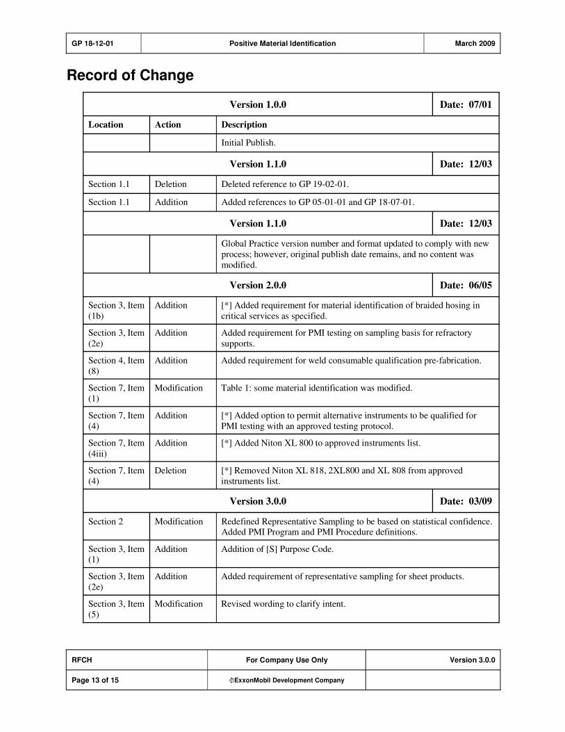
GP 18-12-01 Positive Material Identification March 2009
RFCH For Company Use Only Version 3.0.0
Page 13 of 15 ExxonMobil Development Company
Record of Change
Version 1.0.0 Date: 07/01
Location Action Description
Initial Publish.
Version 1.1.0 Date: 12/03
Section 1.1 Deletion Deleted reference to GP 19-02-01.
Section 1.1 Addition Added references to GP 05-01-01 and GP 18-07-01.
Version 1.1.0 Date: 12/03
Global Practice version number and format updated to comply with new
process; however, original publish date remains, and no content was
modified.
Version 2.0.0 Date: 06/05
Section 3, Item
(1b)
Addition [*] Added requirement for material identification of braided hosing in
critical services as specified.
Section 3, Item
(2e)
Addition Added requirement for PMI testing on sampling basis for refractory
supports.
Section 4, Item
(8)
Addition Added requirement for weld consumable qualification pre-fabrication.
Section 7, Item
(1)
Modification Table 1: some material identification was modified.
Section 7, Item
(4)
Addition [*] Added option to permit alternative instruments to be qualified for
PMI testing with an approved testing protocol.
Section 7, Item
(4iii)
Addition [*] Added Niton XL 800 to approved instruments list.
Section 7, Item
(4)
Deletion [*] Removed Niton XL 818, 2XL800 and XL 808 from approved
instruments list.
Version 3.0.0 Date: 03/09
Section 2 Modification Redefined Representative Sampling to be based on statistical confidence. Added PMI Program and PMI Procedure definitions.
Section 3, Item (1)
Addition Addition of [S] Purpose Code.
Section 3, Item
(2e)
Addition Added requirement of representative sampling for sheet products.
Section 3, Item
(5)
Modification Revised wording to clarify intent.

GP 18-12-01 Positive Material Identification March 2009
RFCH For Company Use Only Version 3.0.0
Page 14 of 15 ExxonMobil Development Company
Section 4, Item
(1)
Deletion Removed [S] purpose code.
Section 4, Item
(2)
Addition Added requirements regarding witness of PMI by Owner’s Inspector.
Added [A].
Section 4, Item
(5b)
Modification Specified requirements on final construction verification.
Section 4, Item
(8a)
Addition Added button size requirements.
Section 7,
Table 1
Addition Added Alloy C-276 and ASTM A533 to Table 1.
Section 7, Item
(4)
Deletion Removed approved instruments list.
Section 7, Item (4)
Addition Added guidance for qualified PMI instruments.
All Global
Practices
Modifications To standardize the format of the Global Practices and to meet other requirements, the following changes have been implemented:
"For ExxonMobil Use Only" has been replaced with "For Company Use
Only."
A copyright waiver has been added in the first page Footer.
The definition of asterisks in the Scope has been deleted. The asterisk is
now defined in the Purpose Code attachment and is used within brackets
as other Purpose Codes.
Multiple paragraphs within a Section have been numbered.
The standard text for Required References has been modified.
The standard text for Additional Requirements has been modified.
The [S] Purpose Code has been modified.
The following Purpose Codes have been added:
[*] for additional information or decision required of Owner's
Engineer.
[A] for approval requirements before beginning work or finalizing
design.
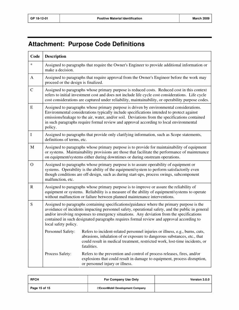
GP 18-12-01 Positive Material Identification March 2009
RFCH For Company Use Only Version 3.0.0
Page 15 of 15 ExxonMobil Development Company
Attachment: Purpose Code Definitions
Code Description
* Assigned to paragraphs that require the Owner's Engineer to provide additional information or
make a decision.
A Assigned to paragraphs that require approval from the Owner's Engineer before the work may
proceed or the design is finalized.
C Assigned to paragraphs whose primary purpose is reduced costs. Reduced cost in this context
refers to initial investment cost and does not include life cycle cost considerations. Life cycle
cost considerations are captured under reliability, maintainability, or operability purpose codes.
E Assigned to paragraphs whose primary purpose is driven by environmental considerations. Environmental considerations typically include specifications intended to protect against
emissions/leakage to the air, water, and/or soil. Deviations from the specifications contained
in such paragraphs require formal review and approval according to local environmental policy.
I Assigned to paragraphs that provide only clarifying information, such as Scope statements,
definitions of terms, etc.
M Assigned to paragraphs whose primary purpose is to provide for maintainability of equipment or systems. Maintainability provisions are those that facilitate the performance of maintenance
on equipment/systems either during downtimes or during onstream operations.
O Assigned to paragraphs whose primary purpose is to assure operability of equipment or
systems. Operability is the ability of the equipment/system to perform satisfactorily even though conditions are off-design, such as during start-ups, process swings, subcomponent
malfunction, etc.
R Assigned to paragraphs whose primary purpose is to improve or assure the reliability of
equipment or systems. Reliability is a measure of the ability of equipment/systems to operate without malfunction or failure between planned maintenance interventions.
S Assigned to paragraphs containing specifications/guidance where the primary purpose is the
avoidance of incidents impacting personnel safety, operational safety, and the public in general and/or involving responses to emergency situations. Any deviation from the specifications
contained in such designated paragraphs requires formal review and approval according to
local safety policy.
Personnel Safety: Refers to incident-related personnel injuries or illness, e.g., burns, cuts, abrasions, inhalation of or exposure to dangerous substances, etc., that
could result in medical treatment, restricted work, lost-time incidents, or
fatalities.
Process Safety: Refers to the prevention and control of process releases, fires, and/or
explosions that could result in damage to equipment, process disruption,
or personnel injury or illness.
GP 19-01-01 Paint and Protective Coatings April 2004
Refining/Chemicals For ExxonMobil Use Only Version 3.0.0
Page 1 of 29 ExxonMobil Development Company
Paint and Protective Coatings
GP 19-01-01
Scope
1) [I] This Global Practice (GP) covers the selection and application of exterior paint and Protective
Coating Systems for structures and equipment. Requirements for protective wrapping systems and galvanizing of structures are also covered.
2) * [I] An asterisk (*) indicates that a decision by the Purchaser is required, or that additional
information is furnished by the Purchaser.

GP 19-01-01 Paint and Protective Coatings April 2004
RFCH For ExxonMobil Use Only Version 3.0.0
Page 2 of 29 ExxonMobil Development Company
Table of Contents
Table of Tables .............................................................................................................. 4
1. Required References ............................................................................................ 5
1.1. Global Practices–ExxonMobil Engineering Practices ................................... 5
1.2. AWS–American Welding Society.................................................................. 5
1.3. AWWA–American Water Works Association................................................ 5
1.4. ASTM–American Society for Testing and Materials ..................................... 5
1.5. NACE–National Association of Corrosion Engineers.................................... 6
1.6. SSPC–The Society for Protective Coatings.................................................. 6
2. Definitions.............................................................................................................. 7
3. Documentation ...................................................................................................... 7
4. Selection of Paint and Coating Systems............................................................. 8
4.1. Painting Service Category ............................................................................ 8
4.2. Use of Galvanizing ....................................................................................... 8
4.3. Types and Brands of Paints and Coatings ................................................... 8
5. Surface Preparation .............................................................................................. 9
6. Application of Paint, Coating, and Wrapping Systems.................................... 10
6.1. Manufacturer's Recommendations ............................................................. 10
6.2. Underground and Underwater Piping ......................................................... 10
6.3. Waterproof Coatings and Underground Concrete Structures ..................... 10
6.4. Manufacturer's Standard Painting for Purchased Equipment ..................... 10
6.5. Steel Piles and Sheet Piling ....................................................................... 11
6.6. Surfaces Not Requiring Painting................................................................. 11
6.7. Shielding of Adjoining or Adjacent Equipment............................................ 11
6.8. Piping and Welded Joints ........................................................................... 12
6.9. Fireproofed or Insulated Equipment and Structures ................................... 12
6.10. Direct Contact Attachment of Structural Steel ............................................ 12
6.11. Repair of Damaged Galvanizing................................................................. 12
6.12. Paint System and Safety Equipment Identification ..................................... 12
7. Inspection and Testing ....................................................................................... 13

GP 19-01-01 Paint and Protective Coatings April 2004
RFCH For ExxonMobil Use Only Version 3.0.0
Page 3 of 29 ExxonMobil Development Company
7.1. Inspection Methods and Acceptance Criteria ............................................. 13
8. Use of Thermal Spray Coatings ......................................................................... 14
9. Metric Equivalents and Alphanumeric Code Descriptions for Use with Tables 7–13 ...................................................................................................................... 14
10. Coating Selection Tables.................................................................................... 16
Record of Change ....................................................................................................... 26
Attachment: Purpose Codes Definitions.................................................................. 29
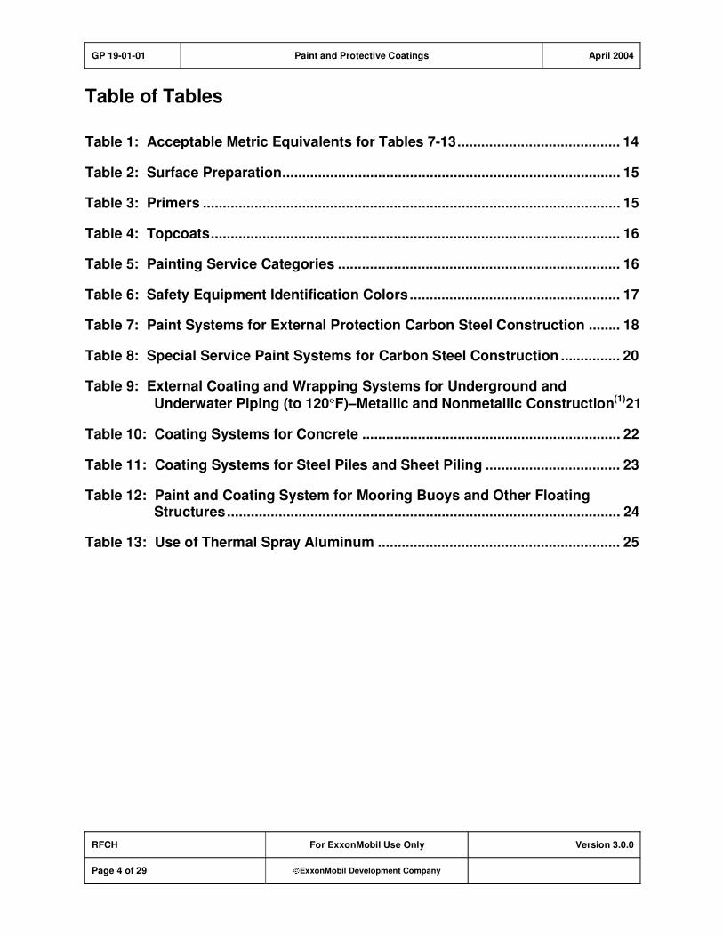
GP 19-01-01 Paint and Protective Coatings April 2004
RFCH For ExxonMobil Use Only Version 3.0.0
Page 4 of 29 ExxonMobil Development Company
Table of Tables
Table 1: Acceptable Metric Equivalents for Tables 7-13......................................... 14
Table 2: Surface Preparation..................................................................................... 15
Table 3: Primers ......................................................................................................... 15
Table 4: Topcoats....................................................................................................... 16
Table 5: Painting Service Categories ....................................................................... 16
Table 6: Safety Equipment Identification Colors..................................................... 17
Table 7: Paint Systems for External Protection Carbon Steel Construction ........ 18
Table 8: Special Service Paint Systems for Carbon Steel Construction ............... 20
Table 9: External Coating and Wrapping Systems for Underground and
Underwater Piping (to 120 F)–Metallic and Nonmetallic Construction(1)21
Table 10: Coating Systems for Concrete ................................................................. 22
Table 11: Coating Systems for Steel Piles and Sheet Piling .................................. 23
Table 12: Paint and Coating System for Mooring Buoys and Other Floating Structures................................................................................................... 24
Table 13: Use of Thermal Spray Aluminum ............................................................. 25
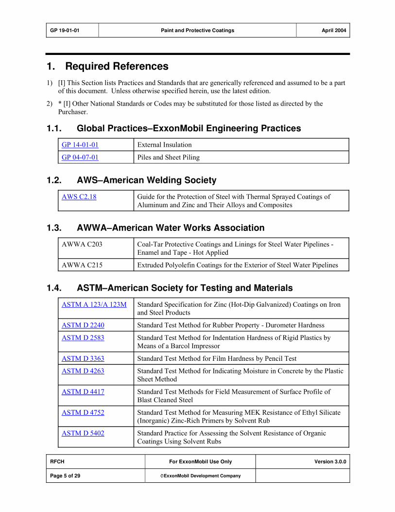
GP 19-01-01 Paint and Protective Coatings April 2004
RFCH For ExxonMobil Use Only Version 3.0.0
Page 5 of 29 ExxonMobil Development Company
1. Required References
1) [I] This Section lists Practices and Standards that are generically referenced and assumed to be a part of this document. Unless otherwise specified herein, use the latest edition.
2) * [I] Other National Standards or Codes may be substituted for those listed as directed by the
Purchaser.
1.1. Global Practices–ExxonMobil Engineering Practices
GP 14-01-01 External Insulation
GP 04-07-01 Piles and Sheet Piling
1.2. AWS–American Welding Society
AWS C2.18 Guide for the Protection of Steel with Thermal Sprayed Coatings of
Aluminum and Zinc and Their Alloys and Composites
1.3. AWWA–American Water Works Association
AWWA C203 Coal-Tar Protective Coatings and Linings for Steel Water Pipelines -
Enamel and Tape - Hot Applied
AWWA C215 Extruded Polyolefin Coatings for the Exterior of Steel Water Pipelines
1.4. ASTM–American Society for Testing and Materials
ASTM A 123/A 123M Standard Specification for Zinc (Hot-Dip Galvanized) Coatings on Iron and Steel Products
ASTM D 2240 Standard Test Method for Rubber Property - Durometer Hardness
ASTM D 2583 Standard Test Method for Indentation Hardness of Rigid Plastics by
Means of a Barcol Impressor
ASTM D 3363 Standard Test Method for Film Hardness by Pencil Test
ASTM D 4263 Standard Test Method for Indicating Moisture in Concrete by the Plastic
Sheet Method
ASTM D 4417 Standard Test Methods for Field Measurement of Surface Profile of
Blast Cleaned Steel
ASTM D 4752 Standard Test Method for Measuring MEK Resistance of Ethyl Silicate (Inorganic) Zinc-Rich Primers by Solvent Rub
ASTM D 5402 Standard Practice for Assessing the Solvent Resistance of Organic
Coatings Using Solvent Rubs
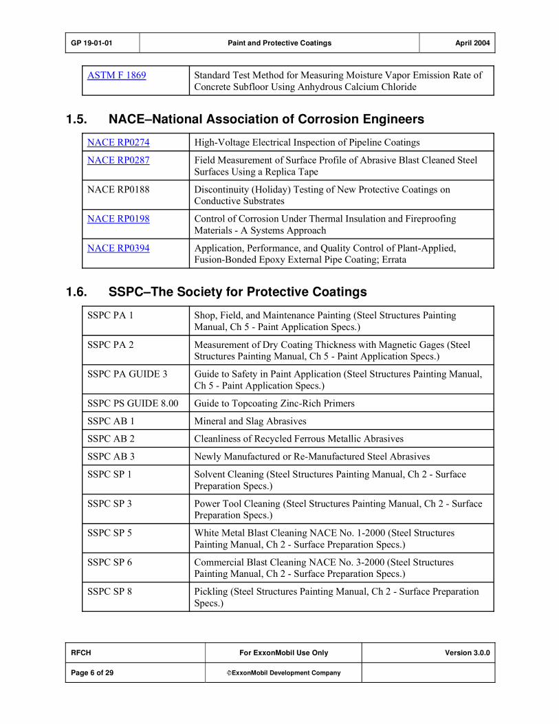
GP 19-01-01 Paint and Protective Coatings April 2004
RFCH For ExxonMobil Use Only Version 3.0.0
Page 6 of 29 ExxonMobil Development Company
ASTM F 1869 Standard Test Method for Measuring Moisture Vapor Emission Rate of
Concrete Subfloor Using Anhydrous Calcium Chloride
1.5. NACE–National Association of Corrosion Engineers
NACE RP0274 High-Voltage Electrical Inspection of Pipeline Coatings
NACE RP0287 Field Measurement of Surface Profile of Abrasive Blast Cleaned Steel
Surfaces Using a Replica Tape
NACE RP0188 Discontinuity (Holiday) Testing of New Protective Coatings on Conductive Substrates
NACE RP0198 Control of Corrosion Under Thermal Insulation and Fireproofing
Materials - A Systems Approach
NACE RP0394 Application, Performance, and Quality Control of Plant-Applied, Fusion-Bonded Epoxy External Pipe Coating; Errata
1.6. SSPC–The Society for Protective Coatings
SSPC PA 1 Shop, Field, and Maintenance Painting (Steel Structures Painting
Manual, Ch 5 - Paint Application Specs.)
SSPC PA 2 Measurement of Dry Coating Thickness with Magnetic Gages (Steel Structures Painting Manual, Ch 5 - Paint Application Specs.)
SSPC PA GUIDE 3 Guide to Safety in Paint Application (Steel Structures Painting Manual,
Ch 5 - Paint Application Specs.)
SSPC PS GUIDE 8.00 Guide to Topcoating Zinc-Rich Primers
SSPC AB 1 Mineral and Slag Abrasives
SSPC AB 2 Cleanliness of Recycled Ferrous Metallic Abrasives
SSPC AB 3 Newly Manufactured or Re-Manufactured Steel Abrasives
SSPC SP 1 Solvent Cleaning (Steel Structures Painting Manual, Ch 2 - Surface
Preparation Specs.)
SSPC SP 3 Power Tool Cleaning (Steel Structures Painting Manual, Ch 2 - Surface Preparation Specs.)
SSPC SP 5 White Metal Blast Cleaning NACE No. 1-2000 (Steel Structures
Painting Manual, Ch 2 - Surface Preparation Specs.)
SSPC SP 6 Commercial Blast Cleaning NACE No. 3-2000 (Steel Structures Painting Manual, Ch 2 - Surface Preparation Specs.)
SSPC SP 8 Pickling (Steel Structures Painting Manual, Ch 2 - Surface Preparation
Specs.)

GP 19-01-01 Paint and Protective Coatings April 2004
RFCH For ExxonMobil Use Only Version 3.0.0
Page 7 of 29 ExxonMobil Development Company
SSPC SP 10 Near-White Metal Blast Cleaning NACE No.2-2000 (Steel Structures
Painting Manual, Ch 2 - Surface Preparation Specs.)
SSPC SP 11 Power Tool Cleaning to Bare Metal
SSPC SP 13 Surface Preparation of Concrete
SSPC VIS 1 Visual Standard for Abrasive Blast Cleaned Steel (Standard Reference
Photographs) Editorial Changes September 1,2000 (Steel Structures Painting Manual, Ch 2 - Surface Preparation Specs.)
SSPC VIS 3 Visual Standard for Power- and Hand-Tool Cleaned Steel (Standard
Reference Photographs)
3) * [R] Vendor shall prepare a detailed Painting Schedule including (but not limited to) the information
listed below, for approval by the Owner's Engineer.
a) Detailed scope
b) Surface preparation
c) Materials
d) Application
e) Inspection procedures and documentation
f) Provisions for handling and storage of paints and coatings at the site
g) Plans for conformance to national, state, and local environmental law
2. Definitions
1) [I] Bare surfaces as referred to in this GP shall be defined as surfaces, equipment, or structures that
are not insulated or fireproofed.
2) [I] Marine atmosphere as referred to in this GP shall be defined as containing a high concentration of
chlorides and water in the air.
3) [I] Intermittent service (see Table 7) is one in which the process temperature cycles on a recurrent
basis, into and out of the 25 F to 300 F ( 4 C to 150 C) range.
3. Documentation
1) [R] Coatings application contractor shall submit proof of certification by the Society for Protective Coatings (SSPC) to SSPC QP1 or QP3 as applicable, or equivalent.
2) [R] Coatings application contractor shall submit a list of its most recent industrial experience plus
names and telephone numbers of people who can verify this experience.
3) [R] Coatings application contractor shall submit plans for Quality Assurance and Quality Control, the names of their coating inspectors and the degree of their training.
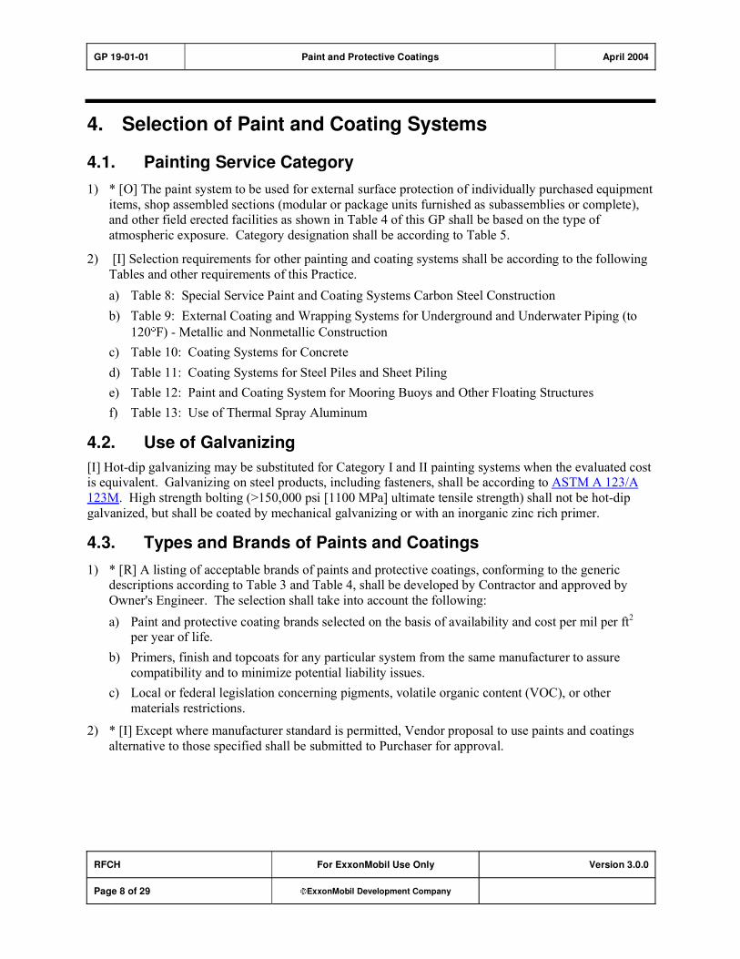
GP 19-01-01 Paint and Protective Coatings April 2004
RFCH For ExxonMobil Use Only Version 3.0.0
Page 8 of 29 ExxonMobil Development Company
4. Selection of Paint and Coating Systems
4.1. Painting Service Category
1) * [O] The paint system to be used for external surface protection of individually purchased equipment
items, shop assembled sections (modular or package units furnished as subassemblies or complete), and other field erected facilities as shown in Table 4 of this GP shall be based on the type of
atmospheric exposure. Category designation shall be according to Table 5.
2) [I] Selection requirements for other painting and coating systems shall be according to the following
Tables and other requirements of this Practice.
a) Table 8: Special Service Paint and Coating Systems Carbon Steel Construction
b) Table 9: External Coating and Wrapping Systems for Underground and Underwater Piping (to
120 F) - Metallic and Nonmetallic Construction
c) Table 10: Coating Systems for Concrete
d) Table 11: Coating Systems for Steel Piles and Sheet Piling
e) Table 12: Paint and Coating System for Mooring Buoys and Other Floating Structures
f) Table 13: Use of Thermal Spray Aluminum
4.2. Use of Galvanizing
[I] Hot-dip galvanizing may be substituted for Category I and II painting systems when the evaluated cost is equivalent. Galvanizing on steel products, including fasteners, shall be according to ASTM A 123/A
123M. High strength bolting (>150,000 psi [1100 MPa] ultimate tensile strength) shall not be hot-dip
galvanized, but shall be coated by mechanical galvanizing or with an inorganic zinc rich primer.
4.3. Types and Brands of Paints and Coatings
1) * [R] A listing of acceptable brands of paints and protective coatings, conforming to the generic descriptions according to Table 3 and Table 4, shall be developed by Contractor and approved by
Owner's Engineer. The selection shall take into account the following:
a) Paint and protective coating brands selected on the basis of availability and cost per mil per ft2
per year of life.
b) Primers, finish and topcoats for any particular system from the same manufacturer to assure
compatibility and to minimize potential liability issues.
c) Local or federal legislation concerning pigments, volatile organic content (VOC), or other
materials restrictions.
2) * [I] Except where manufacturer standard is permitted, Vendor proposal to use paints and coatings
alternative to those specified shall be submitted to Purchaser for approval.

GP 19-01-01 Paint and Protective Coatings April 2004
RFCH For ExxonMobil Use Only Version 3.0.0
Page 9 of 29 ExxonMobil Development Company
5. Surface Preparation
1) [I] Surface preparation methods and materials for carbon steel shall take into account the following:
a) Surface preparation, either in the shop or field, may be employed based upon an economic
evaluation including local, state, or federal legislation concerning blast cleaning abrasives.
b) Equipment and structures to be painted in the field: Where surface preparation alternatives are permitted, Purchaser shall make a surface preparation cost study and specify the optimum method
to be used, taking into account:
i) Local rules or regulations governing hygiene, environment and safety.
ii) Proximity of adjacent structures and equipment liable to damage from abrasives.
iii) Proximity of designated operating areas where personnel may be present.
iv) Any effect on coating performance.
c) Purchaser shall submit the results of evaluations according to Items 1a) or 1b) of this Section to
the Owner's Engineer.
d) Surfaces contaminated by oil and grease shall be solvent cleaned according to SSPC SP 1 prior to
any blast cleaning.
e) Blasting abrasive quality shall be according to SSPC AB 1, SSPC AB 2, or SSPC AB 3, as
applicable.
f) Abrasive material for blast cleaning, consisting solely of steel shot shall not be used for surfaces
to be coated with inorganic zinc-rich primers or fusion-bonded epoxy coatings. A mixture
consisting of steel shot and at least 25 percent (wt) steel grit is acceptable.
g) SSPC SP 11 is suitable surface preparation for small repair areas or for field welds where SSPC
SP 10 or better had been originally specified and/or performed. SSPC SP 11 provides good surface cleanliness, roughly equivalent to SSPC SP 10, and it ensures a minimum surface profile
of 1.0 mil.
2) [I] New concrete surfaces to be coated (other than concrete fireproofing) shall be prepared according to the following:
a) Concrete shall have cured for at least 30 days. Surfaces above grade shall be tested according to
ASTM D 4263 and have no moisture detected. On-grade slabs and surfaces below grade, shall be
tested according to ASTM F 1869 and have a moisture vapor emission of 3 lbs (per 1000 ft2
over 24 hours).
b) Surface preparation of concrete shall be according to SSPC SP 13.
c) Surface defects shall be patched with a material recommended by the coating manufacturer to
provide a smooth surface suitable for the coating application.
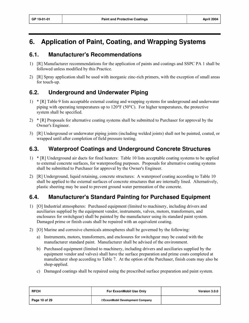
GP 19-01-01 Paint and Protective Coatings April 2004
RFCH For ExxonMobil Use Only Version 3.0.0
Page 10 of 29 ExxonMobil Development Company
6. Application of Paint, Coating, and Wrapping Systems
6.1. Manufacturer's Recommendations
1) [R] Manufacturer recommendations for the application of paints and coatings and SSPC PA 1 shall be
followed unless modified by this Practice.
2) [R] Spray application shall be used with inorganic zinc-rich primers, with the exception of small areas for touch-up.
6.2. Underground and Underwater Piping
1) * [R] Table 9 lists acceptable external coating and wrapping systems for underground and underwater
piping with operating temperatures up to 120 F (50 C). For higher temperatures, the protective
system shall be specified.
2) * [R] Proposals for alternative coating systems shall be submitted to Purchaser for approval by the
Owner's Engineer.
3) [R] Underground or underwater piping joints (including welded joints) shall not be painted, coated, or wrapped until after completion of field pressure testing.
6.3. Waterproof Coatings and Underground Concrete Structures
1) * [R] Underground air ducts for fired heaters: Table 10 lists acceptable coating systems to be applied
to external concrete surfaces, for waterproofing purposes. Proposals for alternative coating systems shall be submitted to Purchaser for approval by the Owner's Engineer.
2) [R] Underground, liquid retaining, concrete structures: A waterproof coating according to Table 10
shall be applied to the external surfaces of concrete structures that are internally lined. Alternatively,
plastic sheeting may be used to prevent ground water permeation of the concrete.
6.4. Manufacturer's Standard Painting for Purchased Equipment
1) [O] Industrial atmospheres: Purchased equipment (limited to machinery, including drivers and auxiliaries supplied by the equipment vendor, instruments, valves, motors, transformers, and
enclosures for switchgear) shall be painted by the manufacturer using its standard paint system.
Damaged prime or finish coats shall be repaired with an equivalent coating.
2) [O] Marine and corrosive chemicals atmospheres shall be governed by the following:
a) Instruments, motors, transformers, and enclosures for switchgear may be coated with the
manufacturer standard paint. Manufacturer shall be advised of the environment.
b) Purchased equipment (limited to machinery, including drivers and auxiliaries supplied by the
equipment vendor and valves) shall have the surface preparation and prime coats completed at
manufacturer shop according to Table 7. At the option of the Purchaser, finish coats may also be
shop-applied.
c) Damaged coatings shall be repaired using the prescribed surface preparation and paint system.

GP 19-01-01 Paint and Protective Coatings April 2004
RFCH For ExxonMobil Use Only Version 3.0.0
Page 11 of 29 ExxonMobil Development Company
6.5. Steel Piles and Sheet Piling
1) * [R] Land structures: The need for protective coatings on steel piles (pipe or structural), and on sheet piling and structural appurtenances shall be specified. Coating systems shall be according to
Table 11.
2) [R] Marine facilities (fresh or salt water). Steel piles (pipe or structural), and sheet piling and
structural appurtenances, shall be coated. Coating systems shall be according to Table 11.
6.6. Surfaces Not Requiring Painting
1) * [I] The following metallic surfaces and materials do not require painting or coating unless otherwise specified:
a) Non-ferrous metals
b) Austenitic stainless steels
c) Galvanized or aluminum-coated carbon steel surfaces
d) Carbon steel surfaces to be insulated, where the equipment is in continuous service with (fluid)
operating temperatures outside the range of 25 F to 300 F (-4 C to 150 C)
2) * [I] The following non-metallic surfaces and materials do not require painting or coating unless specifically required according to Table 10 or by the Owner's Engineer.
a) Building brick, masonry units and wall tile.
b) Concrete structures and foundations.
c) Plastic and plastic coated materials.
d) * Concrete or gunite fireproofing in mild industrial exposure. When specified, concrete or gunite
fireproofing shall be top-coated with two coats of 100 percent acrylic latex paint (Table 3 Code a). Epoxy coatings and silane or silicate waterproofing penetrant treatments are also acceptable
with Owner's Engineer approval.
6.7. Shielding of Adjoining or Adjacent Equipment
[M] Temporary shielding shall be used during any surface preparation and application of coatings to prevent damage or contamination to adjoining or adjacent equipment from abrasives, water, dust, or paint.
Such equipment includes (but is not limited to):
1) Exposed machined surfaces (i.e., operating shafts, couplings, lubrication fittings, linkages, valve stems)
2) Glass (used for instrument cases, level gauges, lighting fixtures)
3) Exposed surfaces of packing glands, seals and bearings
4) Equipment openings (i.e., air intakes, vents, cooling air inlets)
5) Information and identification labels (i.e., switch plates, instrument dials, nameplates, caution and
warning signs)
6) Exposed austenitic stainless steel surfaces�contamination resulting from overspray or spillage shall be removed

GP 19-01-01 Paint and Protective Coatings April 2004
RFCH For ExxonMobil Use Only Version 3.0.0
Page 12 of 29 ExxonMobil Development Company
6.8. Piping and Welded Joints
* [R], [C] The following aboveground piping joints (including all welds and bonds) shall be left unprimed
and unpainted for examination during field pressure testing (leak testing):
1) Joints requiring sensitive leak tests
2) Joints located in an environmentally sensitive area as specified by the Owner's Engineer
3) Where Type M fluids (per ASME B31.3) are contained
6.9. Fireproofed or Insulated Equipment and Structures
1) [R] Protective coating systems for use under thermal insulation shall be according to Table 7.
2) [R] Bare metal surfaces of piping, vessel nozzles and manways, structural steel extensions and similar
attachments extending beyond fireproofing or insulation shall be protected with a complete coating
system according to the painting service category for the bare steel at the equipment operating temperature.
3) * [R] Owner's Engineer shall specify protective coatings or wrapped aluminum foil sheathing
according to GP 14-01-01, to protect thermally insulated austenitic stainless steel equipment from
chloride stress corrosion cracking.
4) [I] The minimum operating temperature of a vessel, exchanger or other equipment shall be considered when determining the need for coating beneath insulation.
5) * [M] When specified by the Owner�s Engineer, personnel protection cages will be used instead of
insulation to minimize the occurrence of corrosion under insulation.
6.10. Direct Contact Attachment of Structural Steel
[R], [M] Direct contact surfaces of non-galvanized components which are bolted or attached with
intermittent welding, shall be protected according to the following:
1) Surfaces shall be painted with the primer system according to the specified painting service category.
2) A coating of an elastomeric mastic or petrolatum paste and tape shall be applied to both contact
surfaces. Coating shall be 1/8 in. (3 mm) wet film thickness.
3) After erection, the space between plates and at the outer edges shall be filled with elastomeric mastic before finish coat application.
6.11. Repair of Damaged Galvanizing
* [R], [M] Galvanized steel that is damaged by welding shall be repaired with a suitable coating system as approved by the Owner's Engineer.
6.12. Paint System and Safety Equipment Identification
1) * [S] Painting requirements covering number or service identification of equipment, pipelines and
structures, and special color identification shall be specified. If not otherwise specified, the identification colors listed in Table 6 shall be used.
2) [M] Information regarding the Protective Coating System shall be stenciled on the exterior surface of
equipment and structures according to the following:

GP 19-01-01 Paint and Protective Coatings April 2004
RFCH For ExxonMobil Use Only Version 3.0.0
Page 13 of 29 ExxonMobil Development Company
a) Vessels and tankage�shell and roof, interior and exterior as applicable:
i) Surface preparation�identify method(s) used (i.e., SSPC SP 6).
ii) Identify the manufacturer and product number for each coat�primer, intermediate, and finish
coats.
iii) Month and year of application.
iv) Contractor name.
v) Lead, chromium, and or cadmium content of any coating.
b) * [I] Other equipment including pipelines, and structures�the need for and extent of identifying
information shall be specified.
c) The location of identifying information according to Items 2a) and 2b) above shall be specified. Stencil lettering shall be approximately 1½ in. (40 mm) high.
7. Inspection and Testing
[I] The term Inspector, used in this Practice, refers to the Owner's representative. For marine, severe
industrial, chemical, or lining applications, the Inspector shall be a certified NACE International Coating
Inspector or equivalent.
7.1. Inspection Methods and Acceptance Criteria
1) [R], [M] Surface preparation cleanliness shall be evaluated using SSPC VIS 1 or SSPC VIS 3 visual
standards. Surface roughness (anchor pattern or profile) shall be determined according to NACE
RP0287 or ASTM D 4417.
2) [R], [M] Dry film thickness measurement shall be made of each coat and of the total system,
according to the procedure established by SSPC PA 2, with the exception that the inspector may inspect any and all areas and make as many measurements as deemed necessary.
3) * [R] Additional inspection of coatings applied to tank and vessel interiors:
a) Continuity shall be checked according to NACE RP0188.
b) Degree of cure shall be determined using a solvent wipe test and/or a film hardness test. Where a
film hardness test is appropriate, the procedure shall be according to ASTM D 3363, ASTM D
2583, or ASTM D 2240 as deemed suitable for the particular coating.
Test methods and procedures shall be developed with the Owner's Engineer for the specific
installation.
4) [R] Protective coatings for underground or submarine pipelines shall be inspected according to the
appropriate specification listed in Table 9.
5) * [R], [M] Compliance with governing specifications shall be checked by the Inspector during the entire course of surface preparation and application of the paint, coating or wrapping systems.
6) * [R], [M] Work shall not proceed with the next step in the system sequence (i.e., surface preparation,
priming, intermediate, finish coat application) until the previous work has been inspected and
approved by the Inspector.
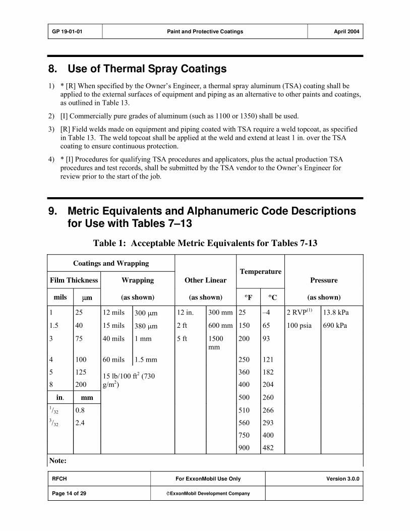
GP 19-01-01 Paint and Protective Coatings April 2004
RFCH For ExxonMobil Use Only Version 3.0.0
Page 14 of 29 ExxonMobil Development Company
8. Use of Thermal Spray Coatings
1) * [R] When specified by the Owner�s Engineer, a thermal spray aluminum (TSA) coating shall be applied to the external surfaces of equipment and piping as an alternative to other paints and coatings,
as outlined in Table 13.
2) [I] Commercially pure grades of aluminum (such as 1100 or 1350) shall be used.
3) [R] Field welds made on equipment and piping coated with TSA require a weld topcoat, as specified
in Table 13. The weld topcoat shall be applied at the weld and extend at least 1 in. over the TSA coating to ensure continuous protection.
4) * [I] Procedures for qualifying TSA procedures and applicators, plus the actual production TSA
procedures and test records, shall be submitted by the TSA vendor to the Owner�s Engineer for
review prior to the start of the job.
9. Metric Equivalents and Alphanumeric Code Descriptions for Use with Tables 7–13
Table 1: Acceptable Metric Equivalents for Tables 7-13
Coatings and Wrapping
Film Thickness Wrapping Other Linear
Temperature
Pressure
mils m (as shown) (as shown) F C (as shown)
1 25 12 mils 300 m 12 in. 300 mm 25 �4 2 RVP(1)
13.8 kPa
1.5 40 15 mils 380 m 2 ft 600 mm 150 65 100 psia 690 kPa
3 75 40 mils 1 mm 5 ft 1500 mm
200 93
4 100 60 mils 1.5 mm 250 121
5 125 360 182
8 200 15 lb/100 ft
2 (730
g/m2) 400 204
in. mm 500 260
1/32 0.8 510 266
3/32 2.4 560 293
750 400
900 482
Note:

GP 19-01-01 Paint and Protective Coatings April 2004
RFCH For ExxonMobil Use Only Version 3.0.0
Page 15 of 29 ExxonMobil Development Company
Coatings and Wrapping
Film Thickness Wrapping Other Linear
Temperature
Pressure
mils m (as shown) (as shown) F C (as shown)
1) RVP (reed vapor pressure)
Table 2: Surface Preparation
Code Description
1 SSPC SP 5/NACE #1 White Metal Blast Cleaning
2 SSPC SP 10/NACE #2 Near White Blast Cleaning
3 SSPC SP 6/NACE #3 Commercial Blast Cleaning
4 SSPC SP 11 Power Tool Cleaning to Bare Metal
Table 3: Primers
Code Generic Descriptions Typical Dry Film
Thickness–Mils(2)
Z(1)
inorganic zinc 3�4
A acrylic latex 1�2
S silicone high-temperature zinc-rich 1
E epoxy 3�6
U moisture cured urethane 3�4
Notes:
1) Manufacturer�s requirements and SSPC PS GUIDE 8.00 shall be followed when
applying topcoats to inorganic zinc rich primers.
2) These are typical dry film thicknesses; use manufacturer�s recommended values.

GP 19-01-01 Paint and Protective Coatings April 2004
RFCH For ExxonMobil Use Only Version 3.0.0
Page 16 of 29 ExxonMobil Development Company
Table 4: Topcoats
Code Generic Descriptions
Typical Dry
Film Thickness
(mils)
a 100 percent acrylic latex topcoat 1.5�3.0
b phenolic aluminum (two-component) 1.0
c coal tar epoxy (polyamide or amine cured) 8�16
e epoxy 4�8
h silicone hi-temperature aluminum (or color) 1.0�1.5
m thermal spray aluminum 10�20
n epoxy-phenolic (novolac) 5�8
p aliphatic acrylic polyurethane 2�4
s silicone-acrylic 1�2
t temperature indicating (silicone-based) 1.5
u moisture cured urethane 3�5
v vinyl anti-fouling 1�2
w petrolatum wax tape
Note: These are typical dry film thickness; use manufacturer recommended values.
10. Coating Selection Tables
Table 5: Painting Service Categories
Category Description
Environmental
Corrosion
Rate
Table 7 Reference
and Special Conditions
Industrial atmospheres:
Class I (mild) 1 mpy or less
I
Class II (normal) 3 mpy or less
Sweating pipelines and equipment shall be
coated according to requirements of Marine Atmospheres

GP 19-01-01 Paint and Protective Coatings April 2004
RFCH For ExxonMobil Use Only Version 3.0.0
Page 17 of 29 ExxonMobil Development Company
Category Description
Environmental
Corrosion
Rate
Table 7 Reference
and Special Conditions
Marine atmosphere II
Severe industrial atmosphere
Over 3 mpy 1. Bare steel flare structures, all structural components of fixed platforms, and associated
bolting, shall be coated for marine atmosphere,
except where the location is designated as Category I, industrial (mild)
2. Bare steel structures and equipment within
150-ft radius of a salt water or brackish water cooling tower shall be coated for Marine
Atmosphere (regardless of other designated
atmospheric exposure conditions for the
location).
III Corrosive chemical
atmosphere
Over 3 mpy As required, modifications of different
painting systems may be specified for the
specific chemical(s) handled
Table 6: Safety Equipment Identification Colors
Equipment Identification Colors
Fire protection equipment(1), including
1. Fire equipment cabinets Red
2. Mounting areas for portable fire extinguishers
Pressure relief (Pr) devices and associated car sealed block valves:
1. Conventional Pr valves Yellow
2. Bellows type Pr valves Body�Yellow; Bonnet�Red
3. Car sealed block valves Yellow
Note:
1) Excludes mobile fire fighting equipment (i.e., automotive fire apparatus).

GP 19-01-01 Paint and Protective Coatings April 2004
RFCH For ExxonMobil Use Only Version 3.0.0
Page 18 of 29 ExxonMobil Development Company
Table 7: Paint Systems for External Protection Carbon Steel Construction
Surface Preparation and Coating Code(1)(2)
Industrial
Atmosphere
Corrosive Chemical
Atmosphere
Service
Class I
(Mild)
Class II
(Normal)
Severe
Industrial or
Marine
AtmosphereChemical
Fumes
Chemical
Liquids
Handled or
Stored
Bare carbon steel surfaces 250 F and below:
1. Structural steel, equipment
(including pressure vessels and exchangers), and piping
3Aaa or
3Ee
2Zaa or
2Zep or
2Uuu
2Z(3)
2Uuu
2ee or
2nn
2ee or
2nn
2. Misc. iron and steel work in pump
slab areas to 5 ft above grade where corrosive chemicals handled
2ee or
2nn
2ee or
2nn �
2ee or
2nn
3. Structures, equipment, and piping
exposed to chemical fumes
2ee or
2nn
2ee or
2nn �
4. Tanks and storage vessels
a. External surfaces
3Aaa
or
3Ee
2Zaa or
2Zep or
2Uuu
b. Roof of floating roof tanks 2Zee or
2Zbb
2Zee or
2Zbb
(2Z, 2Zaa,
2Zep, 2Zuu) (3)
or
2Uuu or
2Znn
2ee or
2nn or
2Znn
5. Equipment operating below dew
point that sweats
2Z(3) 2ee or
2nn
Purchased equipment (individual commodity purchase with painting by Vendor) limited to:
1. Rotating machinery including drivers, and auxiliary vessels and
piping by equipment vendor
Manufacturer standard
2Z(3) 2ee or
2nn
2. Valves Manufacturer
standard
2Z(3) 2ee or 2nn
3. Instruments, motors, transformers, and enclosures for switchgear
Manufacturer standard
Manufacturer standard suitable for the specified environment
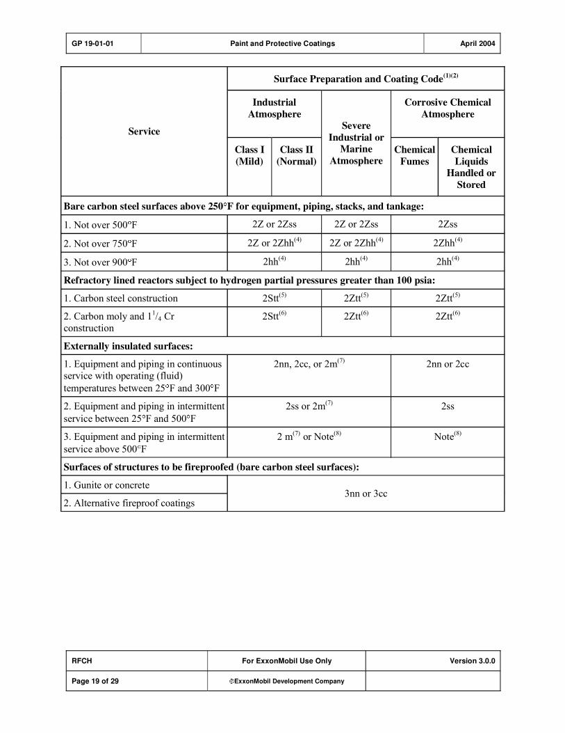
GP 19-01-01 Paint and Protective Coatings April 2004
RFCH For ExxonMobil Use Only Version 3.0.0
Page 19 of 29 ExxonMobil Development Company
Surface Preparation and Coating Code(1)(2)
Industrial
Atmosphere
Corrosive Chemical
Atmosphere
Service
Class I
(Mild)
Class II
(Normal)
Severe
Industrial or
Marine
AtmosphereChemical
Fumes
Chemical
Liquids
Handled or
Stored
Bare carbon steel surfaces above 250 F for equipment, piping, stacks, and tankage:
1. Not over 500 F 2Z or 2Zss 2Z or 2Zss 2Zss
2. Not over 750 F 2Z or 2Zhh(4)
2Z or 2Zhh(4)
2Zhh(4)
3. Not over 900 F 2hh(4)
2hh(4)
2hh(4)
Refractory lined reactors subject to hydrogen partial pressures greater than 100 psia:
1. Carbon steel construction 2Stt(5)
2Ztt(5)
2Ztt(5)
2. Carbon moly and 11/4 Cr
construction
2Stt(6)
2Ztt(6)
2Ztt(6)
Externally insulated surfaces:
1. Equipment and piping in continuous
service with operating (fluid)
temperatures between 25 F and 300 F
2nn, 2cc, or 2m(7)
2nn or 2cc
2. Equipment and piping in intermittent
service between 25 F and 500 F
2ss or 2m(7)
2ss
3. Equipment and piping in intermittent
service above 500 F
2 m(7)
or Note(8)
Note(8)
Surfaces of structures to be fireproofed (bare carbon steel surfaces):
1. Gunite or concrete
2. Alternative fireproof coatings 3nn or 3cc
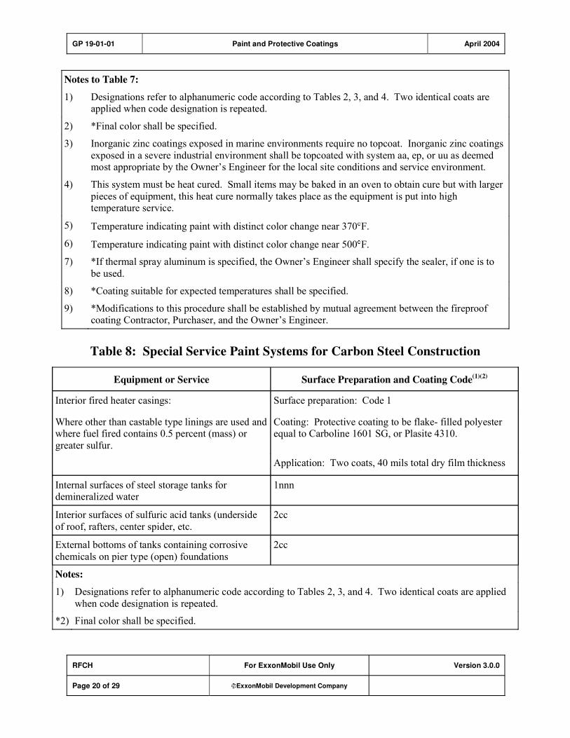
GP 19-01-01 Paint and Protective Coatings April 2004
RFCH For ExxonMobil Use Only Version 3.0.0
Page 20 of 29 ExxonMobil Development Company
Notes to Table 7:
1) Designations refer to alphanumeric code according to Tables 2, 3, and 4. Two identical coats are applied when code designation is repeated.
2) *Final color shall be specified.
3) Inorganic zinc coatings exposed in marine environments require no topcoat. Inorganic zinc coatings
exposed in a severe industrial environment shall be topcoated with system aa, ep, or uu as deemed most appropriate by the Owner�s Engineer for the local site conditions and service environment.
4) This system must be heat cured. Small items may be baked in an oven to obtain cure but with larger
pieces of equipment, this heat cure normally takes place as the equipment is put into high temperature service.
5) Temperature indicating paint with distinct color change near 370 F.
6) Temperature indicating paint with distinct color change near 500 F.
7) *If thermal spray aluminum is specified, the Owner�s Engineer shall specify the sealer, if one is to
be used.
8) *Coating suitable for expected temperatures shall be specified.
9) *Modifications to this procedure shall be established by mutual agreement between the fireproof coating Contractor, Purchaser, and the Owner�s Engineer.
Table 8: Special Service Paint Systems for Carbon Steel Construction
Equipment or Service Surface Preparation and Coating Code(1)(2)
Interior fired heater casings: Surface preparation: Code 1
Where other than castable type linings are used and where fuel fired contains 0.5 percent (mass) or
greater sulfur.
Coating: Protective coating to be flake- filled polyester equal to Carboline 1601 SG, or Plasite 4310.
Application: Two coats, 40 mils total dry film thickness
Internal surfaces of steel storage tanks for demineralized water
1nnn
Interior surfaces of sulfuric acid tanks (underside
of roof, rafters, center spider, etc.
2cc
External bottoms of tanks containing corrosive
chemicals on pier type (open) foundations
2cc
Notes:
1) Designations refer to alphanumeric code according to Tables 2, 3, and 4. Two identical coats are applied
when code designation is repeated.
*2) Final color shall be specified.

GP 19-01-01 Paint and Protective Coatings April 2004
RFCH For ExxonMobil Use Only Version 3.0.0
Page 21 of 29 ExxonMobil Development Company
Table 9: External Coating and Wrapping Systems for Underground and
Underwater Piping (to 120 F)–Metallic and Nonmetallic Construction(1)
Service for Carbon Steel Piping(4)(7)
Surface Preparation and Coating Code(1)(2)(4)
A. Pipeline enamel, single wrap system(2)
consisting of:
1. Surface preparation: Code 3(3)
2. Coal tar or asphalt primer
3. Hot coal tar or asphalt enamel (3/32 in.
1/32 in. thick).
4. Single layer of nominal 15 lb/100 ft2 felt, saturated
and bonded to enamel.
1. Underground�sand and loamy soils
B. Extruded thermoplastic jacket(5)
, minimum 40 mils
thickness; with heat-shrink sleeves to protect field welded
piping joints.
2. Underground�high shrinkage clay soil A. Piping enamel, double coat�double wrap system(2)
consisting of:
(Clay soils which exert pressure against the
coated pipe during wetting and drying cycles.)
1. Surface preparation: Code 3(3)
2. Coal tar or asphalt primer.
3. Hot coal tar or asphalt enamel (3/32 in 1/32 in. thick).
4. Glass fiber wrap.
5. Hot coal tar or asphalt enamel seal (1/32 in (min).
6. Single layer of nominal 15 lb/100 ft2 Type coal tar or
asphalt saturated felt, bonded to enamel.
B. Extruded thermoplastic jacket(5)
, minimum 60 mils
thickness, with heat-shrink sleeves to protect field welded piping joints.
3. Underground�soils having ground water
continually present (marshy) and underwater
piping(6)
C. Fusion bonded epoxy applied according to NACE RP0394
at a total film thickness to be determined by the Owner�s Engineer.

GP 19-01-01 Paint and Protective Coatings April 2004
RFCH For ExxonMobil Use Only Version 3.0.0
Page 22 of 29 ExxonMobil Development Company
Notes to Table 9:
1) *For temperatures over 120 F, the protective system shall be specified by the Owner�s Engineer.
2) Coal tar coating shall conform to AWWA C203. Asphalt may be substituted where coal tar is not
available or not permitted by local rules and regulations. Asphalt primer and enamel type, or properties, shall be specified.
3) Surface preparation Code designation refers to Table 2.
4) *Underground piping used for air ducts to fired heaters shall also be internally coated. Coating type shall be specified.
5) Extruded thermoplastic jacket shall conform to AWWA C215.
6) Underwater piping requiring negative buoyancy shall have a wire mesh reinforced concrete jacket over
the pipeline coating system.
7) *Owner�s Engineer shall specify a rock shield when required.
Table 10: Coating Systems for Concrete
Surface Preparation and Coating
Code(1)(2)
Service
(Corrosive) (Nonclassified)
Corrosive chemical areas:
1. Pump slabs:
Concrete surfaces including top and inside faces of curb enclosures, fireproofing up to 5 ft above slab, all foundation
and slab surfaces with enclosures.
�
2. Paved areas around process equipment (towers, exchangers,
etc.):
Surface preparation:
per Section 5 Item 2)Coatings: ee or nn or
cc
Item 1 above shall apply only where appreciable spillage is
anticipated (such as at flanged joints, etc.). Otherwise,
concrete or fireproofed surfaces shall not be painted.
3. Tank foundations:
Foundations for tanks containing corrosive chemicals.
External coating on outer vertical surface of foundation
downward 12 in. minimum below finished grade.

GP 19-01-01 Paint and Protective Coatings April 2004
RFCH For ExxonMobil Use Only Version 3.0.0
Page 23 of 29 ExxonMobil Development Company
Surface Preparation and Coating
Code(1)(2)
Service
(Corrosive) (Nonclassified)
Underground concrete structures, external surfaces:
1. Fired heater air ducts(3)
Surface
preparation:
according to Section 5 Item 2
Coatings: Code cc
or a hot applied asphalt or coal tar
enamel
2. Liquid retaining structures �
(3/32 in.
1/32 in.
thick)(4)
Notes:
1) Designations refer to alphanumeric code according to Table 4. Two identical coats are applied when
Code designation is repeated.
2) *Final color shall be specified where a paint series is shown.
3) If cast-in-place concrete box construction is used, the concrete foundation mat shall be cast and coated
with coal tar-polyamide epoxy before constructing the duct.
4) Coating properties:
Coal tar according to AWWA C203.
Asphalt coating type or properties shall be specified.
Table 11: Coating Systems for Steel Piles and Sheet Piling
ServiceSurface Preparation
and Coating Code(1)
Land Structures:
Piles and sheet piling 1.
Coat from 2 ft below permanent ground water level to top of piles
(sheet piling), or from 5 ft below final grade to top of piles (sheet
piling), whichever is less.
2. Sheet Piling
In addition to the above, the groove at sheet piling interlocks shall not
be coated.
1c or 1cc
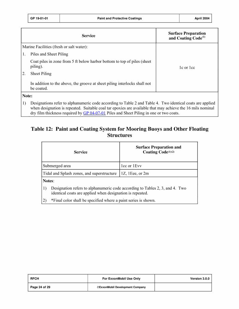
GP 19-01-01 Paint and Protective Coatings April 2004
RFCH For ExxonMobil Use Only Version 3.0.0
Page 24 of 29 ExxonMobil Development Company
ServiceSurface Preparation
and Coating Code(1)
Marine Facilities (fresh or salt water):
Piles and Sheet Piling 1.
Coat piles in zone from 5 ft below harbor bottom to top of piles (sheet
piling).
Sheet Piling 2.
In addition to the above, the groove at sheet piling interlocks shall not be coated.
1c or 1cc
Note:
1) Designations refer to alphanumeric code according to Table 2 and Table 4. Two identical coats are applied
when designation is repeated. Suitable coal tar epoxies are available that may achieve the 16 mils nominal
dry film thickness required by GP 04-07-01 Piles and Sheet Piling in one or two coats.
Table 12: Paint and Coating System for Mooring Buoys and Other Floating
Structures
Service
Surface Preparation and
Coating Code(1)(2)
Submerged area 1cc or 1Evv
Tidal and Splash zones, and superstructure 1Z, 1Eee, or 2m
Notes:
1) Designation refers to alphanumeric code according to Tables 2, 3, and 4. Two identical coats are applied when designation is repeated.
2) *Final color shall be specified where a paint series is shown.
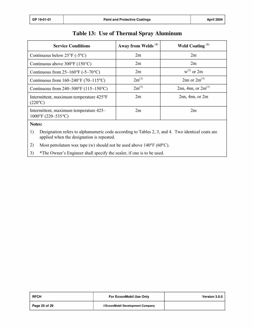
GP 19-01-01 Paint and Protective Coatings April 2004
RFCH For ExxonMobil Use Only Version 3.0.0
Page 25 of 29 ExxonMobil Development Company
Table 13: Use of Thermal Spray Aluminum
Service Conditions Away from Welds (1)
Weld Coating (1)
Continuous below 25 F (-5 C) 2m 2m
Continuous above 300 F (150 C) 2m 2m
Continuous from 25�160 F (-5�70 C) 2m w(2) or 2m
Continuous from 160�240 F (70�115 C) 2m(3)
2nn or 2m(3)
Continuous from 240�300 F (115�150 C) 2m(3)
2nn, 4nn, or 2m(3)
Intermittent, maximum temperature 425 F
(220 C)
2m 2nn, 4nn, or 2m
Intermittent, maximum temperature 425�
1000 F (220�535 C)
2m 2m
Notes:
1) Designation refers to alphanumeric code according to Tables 2, 3, and 4. Two identical coats are
applied when the designation is repeated.
2) Most petrolatum wax tape (w) should not be used above 140 F (60 C).
3) *The Owner�s Engineer shall specify the sealer, if one is to be used.

GP 19-01-01 Paint and Protective Coatings April 2004
RFCH For ExxonMobil Use Only Version 3.0.0
Page 26 of 29 ExxonMobil Development Company
Record of Change
Version 1.0.0 Date: 03/02
Location Action Description
Initial Publish.
Version 2.0.0 Date: 09/03
Section 1 Addition Added reference to AWS C2.18 (created new Section 1.2 for AWS).
Subsequent subsections renumbered accordingly.
Section 1 Modification Reference titles updated.
Section 2,
Items 1) and 2)
Modification �Used� replaced with �referred to.�
Section 3,
Items 1) �3).
Modification �Vendor� replaced with �Coatings application contractor.�
Section 4.1,
Item 1)
Modification �Painting service category� replaced with �paint system.�
Section 4.1,
Item 2)
Addition Added subitem f), �Table 13: Use of Thermal Spray Aluminum.�
Section 4.2 Modification Changed title of section from �Use of Galvanized Coatings� to �Use of
Galvanizing.�
Section 4.3,
Item 1)
Modification Deleted �If a job is contracted, a�� from beginning of sentence.
Changed table references to Table 3 and Table 4 (resulting from
reorganization of tables and addition of new Table 13�see below).
Section 6.3,
Item 2)
Modification Second sentence: Replaced ��for Owner�s Engineer�s approval� with
�for approval by the Owner�s Engineer.�
Section 6.4,
Items 1) and 2)
Modification Commas inserted to replace semicolons in parenthetical list of
�purchased equipment.�
Section 6.6 Modification Deleted �or Coating� from title of section.
Section 6.6,
Item 2)
Modification Paragraph following subitem c) now numbered d).
Section 6.9,
Item 2)
Modification Revised end of sentence as follows:
Original �specified painting service category� changed to �painting
service category for the bare steel at the equipment operating
temperature.�
Section 6.9 Addition Added Item 5) as follows:
�5) * [M] When specified by the Owner�s Engineer, personnel
protection cages will be used instead of insulation to minimize the occurrence of corrosion under insulation.�
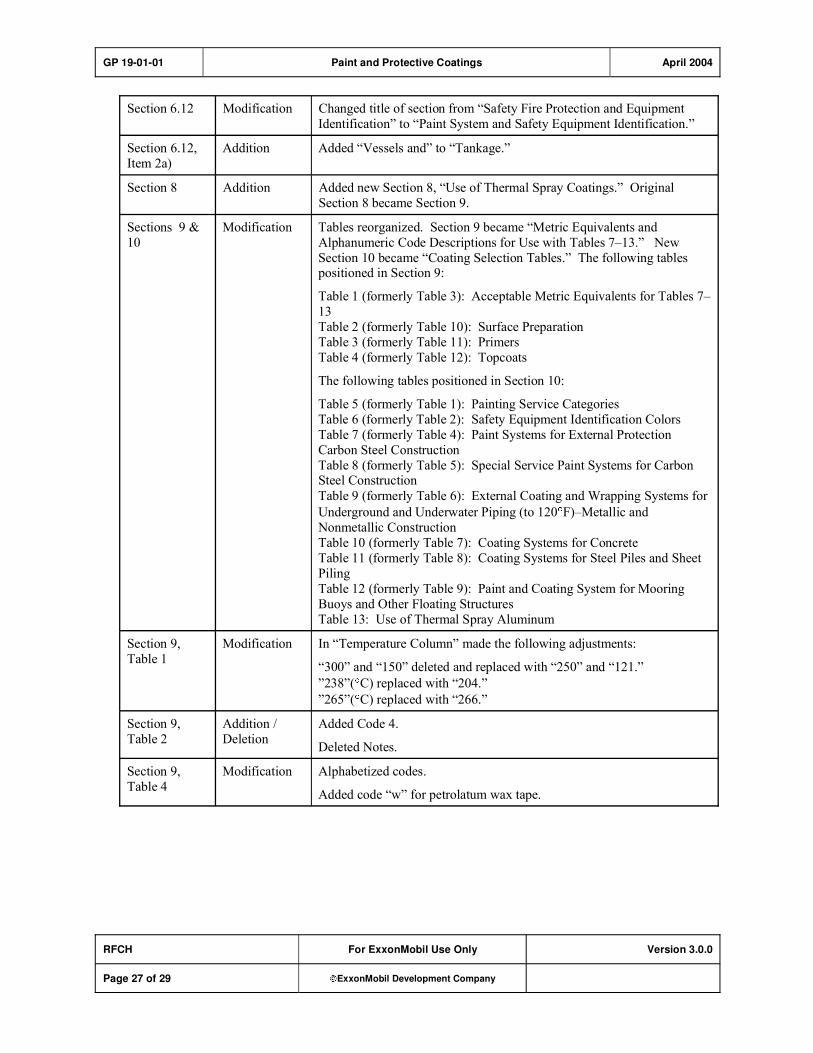
GP 19-01-01 Paint and Protective Coatings April 2004
RFCH For ExxonMobil Use Only Version 3.0.0
Page 27 of 29 ExxonMobil Development Company
Section 6.12 Modification Changed title of section from �Safety Fire Protection and Equipment
Identification� to �Paint System and Safety Equipment Identification.�
Section 6.12,
Item 2a)
Addition Added �Vessels and� to �Tankage.�
Section 8 Addition Added new Section 8, �Use of Thermal Spray Coatings.� Original
Section 8 became Section 9.
Sections 9 &
10
Modification Tables reorganized. Section 9 became �Metric Equivalents and
Alphanumeric Code Descriptions for Use with Tables 7�13.� New
Section 10 became �Coating Selection Tables.� The following tables positioned in Section 9:
Table 1 (formerly Table 3): Acceptable Metric Equivalents for Tables 7�
13
Table 2 (formerly Table 10): Surface Preparation
Table 3 (formerly Table 11): Primers
Table 4 (formerly Table 12): Topcoats
The following tables positioned in Section 10:
Table 5 (formerly Table 1): Painting Service Categories
Table 6 (formerly Table 2): Safety Equipment Identification Colors
Table 7 (formerly Table 4): Paint Systems for External Protection
Carbon Steel Construction
Table 8 (formerly Table 5): Special Service Paint Systems for Carbon Steel Construction
Table 9 (formerly Table 6): External Coating and Wrapping Systems for
Underground and Underwater Piping (to 120 F)�Metallic and
Nonmetallic Construction
Table 10 (formerly Table 7): Coating Systems for Concrete
Table 11 (formerly Table 8): Coating Systems for Steel Piles and Sheet
Piling
Table 12 (formerly Table 9): Paint and Coating System for Mooring
Buoys and Other Floating Structures
Table 13: Use of Thermal Spray Aluminum
Section 9,
Table 1
Modification In �Temperature Column� made the following adjustments:
�300� and �150� deleted and replaced with �250� and �121.�
�238�( C) replaced with �204.�
�265�( C) replaced with �266.�
Section 9,
Table 2
Addition /
Deletion
Added Code 4.
Deleted Notes.
Section 9,
Table 4
Modification Alphabetized codes.
Added code �w� for petrolatum wax tape.
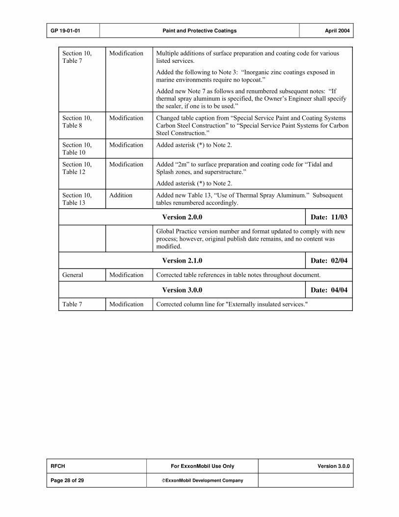
GP 19-01-01 Paint and Protective Coatings April 2004
RFCH For ExxonMobil Use Only Version 3.0.0
Page 28 of 29 ExxonMobil Development Company
Section 10,
Table 7
Modification Multiple additions of surface preparation and coating code for various
listed services.
Added the following to Note 3: �Inorganic zinc coatings exposed in
marine environments require no topcoat.�
Added new Note 7 as follows and renumbered subsequent notes: �If thermal spray aluminum is specified, the Owner�s Engineer shall specify
the sealer, if one is to be used.�
Section 10,
Table 8
Modification Changed table caption from �Special Service Paint and Coating Systems
Carbon Steel Construction� to �Special Service Paint Systems for Carbon
Steel Construction.�
Section 10,
Table 10
Modification Added asterisk (*) to Note 2.
Section 10,
Table 12
Modification Added �2m� to surface preparation and coating code for �Tidal and
Splash zones, and superstructure.�
Added asterisk (*) to Note 2.
Section 10,
Table 13
Addition Added new Table 13, �Use of Thermal Spray Aluminum.� Subsequent
tables renumbered accordingly.
Version 2.0.0 Date: 11/03
Global Practice version number and format updated to comply with new
process; however, original publish date remains, and no content was
modified.
Version 2.1.0 Date: 02/04
General Modification Corrected table references in table notes throughout document.
Version 3.0.0 Date: 04/04
Table 7 Modification Corrected column line for "Externally insulated services."

GP 19-01-01 Paint and Protective Coatings April 2004
RFCH For ExxonMobil Use Only Version 3.0.0
Page 29 of 29 ExxonMobil Development Company
Attachment: Purpose Codes Definitions
Code Description
C Assigned to paragraphs containing specifications whose primary purpose is reduced costs.
Reduced cost in this context refers to initial investment cost and does not include Life-Cycle
cost considerations. Life-Cycle cost considerations are captured under reliability,
maintainability, or operability purpose codes.
E Assigned to paragraphs containing specifications whose primary purpose is driven by
environmental considerations. Environmental considerations typically include specifications
intended to protect against emissions/leakage to the air, water, and/or soil. Deviations from the specifications contained in such paragraphs require formal review and approval according to
local environmental policy.
I Assigned to paragraphs that provide only clarifying information such as Scope statements,
definitions of terms, etc.
M Assigned to paragraphs containing specifications whose primary purpose is to provide for
maintainability of equipment or systems. Maintainability provisions are those that facilitate the
performance of maintenance on equipment/systems either during downtimes or during on-
stream operations.
O Assigned to paragraphs containing specifications whose primary purpose is to assure
operability of equipment or systems. Operability is the ability of the equipment/system to
perform satisfactorily even though conditions are off-design, such as during startups, process swings, subcomponent malfunction, etc.
R Assigned to paragraphs containing specifications whose primary purpose is to improve or
assure the reliability of equipment or systems. Reliability is a measure of the ability of
equipment/systems to operate without malfunction or failure between planned maintenance interventions.
S Assigned to paragraphs containing specifications whose primary purpose is avoidance of
personnel or operational safety incidents. Any deviation from the specifications contained in
such designated paragraphs requires formal review and approval according to local safety policy.
Personnel Safety: Refers to the avoidance of recordable personnel injuries; i.e., burns, cuts,
abrasions, inhalation, or exposure to dangerous substances, etc., that could result in medical treatment, restricted work, lost-time incidents, or
fatalities.
Operational
Safety:
Refers to the prevention and control of process releases, fires, explosions,
etc.
GP 19-03-02 Refractory Linings for Pressure Vessels and Piping May 2005
Refining/Chemicals, Downstream Imperial Oil
For ExxonMobil Use Only Version 2.0.0
Page 1 of 39 ExxonMobil Development Company
Refractory Linings for Pressure Vessels and Piping
GP 19-03-02
Scope
1) [I] This Global Practice (GP) covers requirements for refractory linings in pressure vessels, lines, and piping. It shall apply, but not be limited to, Fluid Catalytic Cracking (FCC), Fluid Coking,
FLEXICOKING, and reforming units. This GP addresses the following:
a) Material selection
b) Testing
c) Shipment
d) Installation
e) Inspection
f) Curing and dryout
2) [I] The following are excluded from this GP:
a) Shotcrete (Gunite) linings (Portland cement and sand)
b) Brick type linings
c) Fired Heater, Incinerator, and Sulfur Combustor linings
3) [I] An asterisk (*) indicates that a decision by Purchaser is required or that additional information is
furnished by Purchaser.

GP 19-03-02 Refractory Linings for Pressure Vessels and Piping May 2005
RFCH, DIOL For ExxonMobil Use Only Version 2.0.0
Page 2 of 39 ExxonMobil Development Company
Table of Contents
Table of Figures ............................................................................................................ 3
Table of Tables .............................................................................................................. 3
1. Required References ............................................................................................ 3
1.1. Global Practices–ExxonMobil Engineering Practices ................................... 3
1.2. ExxonMobil Data Sheets .............................................................................. 3
1.3. API–American Petroleum Institute................................................................ 3
1.4. ASME–American Society of Mechanical Engineers ..................................... 3
1.5. ASTM–American Society for Testing and Materials ..................................... 3
1.6. SSPC–Society for Protective Coatings......................................................... 3
1.7. API RP 936 Certification............................................................................... 3
2. Definitions.............................................................................................................. 3
3. Documentation and Responsibilities .................................................................. 3
4. Refractory Material Preparation Prior to Shipment............................................ 3
5. Design and Installation of Linings ....................................................................... 3
5.1. Refractories .................................................................................................. 3
5.2. Metal Fiber Reinforcement ........................................................................... 3
5.3. V and Y Anchors .......................................................................................... 3
5.4. Hexmetal ...................................................................................................... 3
5.5. Hexalt Anchors ............................................................................................. 3
5.6. Welding ........................................................................................................ 3
5.7. Field Joints in Single Layer Pipe Linings ...................................................... 3
5.8. Shell Openings ............................................................................................. 3
6. Installation ............................................................................................................. 3
7. Repair of Linings................................................................................................... 3
8. Curing and Dryout................................................................................................. 3
8.1. Curing Procedures ....................................................................................... 3
8.2. Dryout/Heating Procedures .......................................................................... 3
8.3. Additional Heat/Dryout Considerations......................................................... 3

GP 19-03-02 Refractory Linings for Pressure Vessels and Piping May 2005
RFCH, DIOL For ExxonMobil Use Only Version 2.0.0
Page 3 of 39 ExxonMobil Development Company
9. Inspection and Testing ......................................................................................... 3
9.1. General......................................................................................................... 3
9.2. Testing of Installed Linings ........................................................................... 3
Appendix: Design and Installation of Lining Details................................................. 3
Record of Change ......................................................................................................... 3
Attachment: Purpose Codes Definitions.................................................................... 3
GP 19-03-02 Refractory Linings for Pressure Vessels and Piping May 2005
RFCH, DIOL For ExxonMobil Use Only Version 2.0.0
Page 4 of 39 ExxonMobil Development Company
Table of Figures
Figure A–1: V-Stud Anchors, Stick or Stud Welded.................................................. 3
Figure A–2: Anchor Layout for Cast or Gunned Linings .......................................... 3
Figure A–3: Y-Anchor for Gunned Dual Layer Linings ............................................. 3
Figure A–4: Typical Hexmetal Layout......................................................................... 3
Figure A–5: Hexmetal Welding Including Termination Strips for Hexmetal Welded Directly to Plate............................................................................................ 3
Figure A–6: Junctions for Hexmetal Attached Directly to Plates............................. 3
Figure A–7: Refractory Lined Edging for Hexmetal Linings Attached Directly to Plate .............................................................................................................. 3
Figure A–8: Hexmetal Used in Dual Component Linings ......................................... 3
Figure A–9: Typical Junctions for Hexmetal Attached to Studs .............................. 3
Figure A–10: Type A, Close-Fitting Lined Pipe Joints .............................................. 3
Figure A–11: Type B Joint for Non-Match-Marked Lined Pipe Spools .................... 3
Figure A–12: Flanged Joint Detail for Fully Lined Pipe Spools................................ 3
Figure A–13: Lining Details for Manway Heads......................................................... 3
Figure A–14: Details for Manway Plugs ..................................................................... 3
Figure A–15: Refractory Linings at Nozzle Connections.......................................... 3
Figure A–16: Repair of Single Layer Lining ............................................................... 3
GP 19-03-02 Refractory Linings for Pressure Vessels and Piping May 2005
RFCH, DIOL For ExxonMobil Use Only Version 2.0.0
Page 5 of 39 ExxonMobil Development Company
Table of Tables
Table 1: V-Anchor Metallurgy...................................................................................... 3
Table 2: Thickness Tolerances for Refractory Linings ............................................. 3
Table 3: Refractory Property Requirements (Customary Units) .............................. 3
Table 4: Refractory Property Requirements (Metric Units) ...................................... 3
Table 5: Procedures for Heating/Dryout of Refractory Linings (1) (2) ........................ 3
Table A–1: Acceptable Metric Equivalents ................................................................ 3
GP 19-03-02 Refractory Linings for Pressure Vessels and Piping May 2005
RFCH, DIOL For ExxonMobil Use Only Version 2.0.0
Page 6 of 39 ExxonMobil Development Company
1. Required References
[I] This Section lists Practices and Standards that are generically referenced and assumed to be a part of this document. Unless otherwise specified herein, use the latest edition.
[I] These requirements may be superseded by this GP and/or by the Job Specification(s). The
requirements set forth in the Job Specification(s) shall supersede the requirements of this GP.
1.1. Global Practices–ExxonMobil Engineering Practices
GP 18-07-01 Welding Procedures
GP 18-12-01 Positive Material Identification
GP 20-01-01 Inspection of Equipment and Materials
1.2. ExxonMobil Data Sheets
ExxonMobil Data
Sheets
ExxonMobil Data Sheet Home Page
D190302C01 Execution Data Sheet - Castable Linings
1.3. API–American Petroleum Institute
API RP 936 Refractory Installation Quality Control Guidelines-Inspection and
Testing Monolithic Refractory Linings and Materials
1.4. ASME–American Society of Mechanical Engineers
ASME SEC VIII D1 B PT UW
Part UW Requirements for Pressure Vessels Fabricated by Welding
1.5. ASTM–American Society for Testing and Materials
ASTM A 167 Standard Specification for Stainless and Heat-Resisting Chromium-
Nickel Steel Plate, Sheet, and Strip
ASTM A 176 Standard Specification for Stainless and Heat-Resisting Chromium Steel Plate, Sheet, and Strip
ASTM A 580/A 580M Standard Specification for Stainless Steel Wire
ASTM A 743/A 743M Standard Specification for Castings, Iron-Chromium, Iron-Chromium-
Nickel, Corrosion Resistant, for General Application
ASTM C 181 Standard Test Method for Workability Index of Fireclay and High-
Alumina Plastic Refractories
GP 19-03-02 Refractory Linings for Pressure Vessels and Piping May 2005
RFCH, DIOL For ExxonMobil Use Only Version 2.0.0
Page 7 of 39 ExxonMobil Development Company
ASTM C 201 Standard Test Method for Thermal Conductivity of Refractories
ASTM C 704 Standard Test Method for Abrasion Resistance of Refractory Materials at Room Temperature
ASTM C 1113 Standard Test Method for Thermal Conductivity of Refractories by Hot
Wire (Platinum Resistance Thermometer Technique)
1.6. SSPC–Society for Protective Coatings
SSPC SP 1 Solvent Cleaning (Steel Structures Painting Manual, Ch 2 - Surface Preparation Specs.)
SSPC SP 3 Power Tool Cleaning (Steel Structures Painting Manual, Ch 2 - Surface
Preparation Specs.)
SSPC SP 7 Joint Surface Preparation Standard Brush-Off Blast Cleaning NACE No. 4: 2000 (Steel Structures Painting Manual, Ch 2–Surface Preparation
Specs.)
1.7. API RP 936 Certification
In application of this GP, service providers shall have demonstrated knowledge of API RP 936.
Individuals requiring certification include:
1) Contractor refractory inspectors
2) Laboratory test technicians
3) Installation field supervisor contractors
4) Vendor technical representatives
5) OEM/Prime contractor personnel responsible for refractory selection/design
2. Definitions
Term [I] Description
Contractor The definition in API RP 936 shall apply. In cases where a general
contractor subcontracts the refractory installation, the Owner shall define
the responsible parties in the Execution Data Sheet (EDS).
Job Specification Developed by the Owner or designated representative(s), this
documentation defines in detail all the design/installation requirements
that are applicable to a specific job. The Job Specification is in addition to the Practices, Codes, and Standards specified in this GP.
Owner's Engineer Owner's designated representative to resolve technical refractory lining
issues.

GP 19-03-02 Refractory Linings for Pressure Vessels and Piping May 2005
RFCH, DIOL For ExxonMobil Use Only Version 2.0.0
Page 8 of 39 ExxonMobil Development Company
Term [I] Description
Pre-installation
qualification
The testing of materials, installation personnel and equipment prior to installation work. Its purpose is to demonstrate ability to comply with
the specified requirements.
3. Documentation and Responsibilities
1) * [I] Information to be furnished by Owner shall be as follows:
a) Provide Job Specification as defined in Section 2.
b) Initiate the Execution Data Sheet (EDS) (see Section 1.2).
c) Designate the Owner's representative Engineer and Inspector(s).
2) [I] Contractor responsibilities include the following. Prior to work execution, Contractor shall:
a) * Prepare and obtain approval for installation and dryout procedures. These include methods and
order of execution for refractory installation, and for types of equipment to be used in installation. It also applies to the quality control plan, Dryout Index (as defined in API RP 936) of products
being installed, and method of dryout, including equipment and setup to control and monitor dryout heating.
b) List of API RP 936 certified personnel.
c) * Complete the EDS with required signoffs.
d) [S] Provide applicable Materials Safety Data Sheets (MSDS) for conditions of purchase and use
and furnish information regarding safety precautions to protect personnel during application and dryout.
e) Direct pre-installation qualification testing to ensure that the installation quality requirements are
met and documented with applicable water ratios.
3) * [I] Equipment Fabricator responsibilities are as follows:
a) Equipment Fabricator shall be responsible for lining protection during shipment and erection of equipment with refractory installed prior to arrival at job site. Fabricator shall provide shipping
instructions, including details of any structures to support the applied linings, to Purchaser for approval by the Owner's Engineer.
b) Equipment Fabricator shall submit the anchor heat-treatment report to Contractor for review prior to anchor installation.
4. Refractory Material Preparation Prior to Shipment
1) [R] All shipments shall have each batch and refractory type clearly identified on the containers.
2) [R] The water ratio used in qualification testing shall be marked on the refractory containers (except
for Type 2h).
3) [R] For Type 2h lining materials:

GP 19-03-02 Refractory Linings for Pressure Vessels and Piping May 2005
RFCH, DIOL For ExxonMobil Use Only Version 2.0.0
Page 9 of 39 ExxonMobil Development Company
a) Refractory shall be pre-sliced at a thickness of 11/4–13/4 in. (30–45 mm) and then packaged in
heat-sealed plastic wrap.
b) The recommended workability index range and that used for the qualification testing shall be
marked on the containers and included with the installation instructions.
5. Design and Installation of Linings
Refer to details shown on Figures A–1 through A–16 in the Appendix.
5.1. Refractories
1) * [R] The EDS shall be approved and pre-installation qualification of materials and applicators shall be satisfactorily completed before installation may commence.
2) [R] Installation Contractor shall ensure that installed physical properties are within the limits
specified in Tables 3 and 4, with the allowances specified in API RP 936. To this end, Installation
Contractor shall specify any additional pre-qualification testing per Section 9.1, Item (2) that is necessary to meet this obligation.
3) [R] Refractories containing calcium silicate type binders (Portland cement) shall not be used at
temperatures above 800 F (427 C).
4) [S] Refractories shall not contain asbestos or asbestos additives.
5) [R] Loose rust, scale, and other foreign matter shall be removed from all surfaces in contact with
refractory per SSPC SP 3 or SSPC SP 7. Oil and grease shall be removed using solvent wipe per SSPC SP 1.
5.2. Metal Fiber Reinforcement
1) [R] Fiber reinforcing shall not be used in refractory for Hexmetal linings.
2) [R] Unless otherwise specified, metal fibers shall be of 304SS material, 1 in. (25 mm) long fibers that
meet the following requirements:
a) Cold-drawn fibers shall be 0.013 in. (0.33 mm) diameter with chemical requirements per ASTM
A 580/A 580M.
b) Melt-extracted fibers shall be 0.013–0.016 in. (0.33–0.41 mm) equivalent diameter with chemical
requirements per ASTM A 743/A 743M.
c) Fibers made by a "Sheet Chopping" process shall be 0.010 x 0.022 in. (0.25 x 0.56 mm) with chemical requirements per ASTM A 167 or ASTM A 176. Straight, corrugated or zigzag type
fibers are acceptable.
3) [R] Cold drawn fibers shall be used for casting installations unless otherwise specified or approved. Melt-extracted or chopped fibers shall be used for gunning and hand packed applications unless
otherwise specified or approved.
4) [R] When metal fiber use is specified, the added fiber content in the refractory shall be 3.5 percent by
weight. Material to which metal fibers have been added shall be designated with an "f" following the refractory type. For example, Type 3f is Type 3 refractory to which metal fibers have been added.
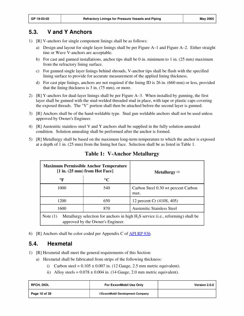
GP 19-03-02 Refractory Linings for Pressure Vessels and Piping May 2005
RFCH, DIOL For ExxonMobil Use Only Version 2.0.0
Page 10 of 39 ExxonMobil Development Company
5.3. V and Y Anchors
1) [R] V-anchors for single component linings shall be as follows:
a) Design and layout for single layer linings shall be per Figure A–1 and Figure A–2. Either straight
tine or Wave V-anchors are acceptable.
b) For cast and gunned installations, anchor tips shall be 0 in. minimum to 1 in. (25 mm) maximum
from the refractory lining surface.
c) For gunned single layer linings behind shrouds, V-anchor tips shall be flush with the specified
lining surface to provide for accurate measurement of the applied lining thickness.
d) For cast pipe linings, anchors are not required if the lining ID is 26 in. (660 mm) or less, provided
that the lining thickness is 3 in. (75 mm), or more.
2) [R] Y-anchors for dual-layer linings shall be per Figure A–3. When installed by gunning, the first layer shall be gunned with the stud-welded threaded stud in place, with tape or plastic caps covering
the exposed threads. The "V" portion shall then be attached before the second layer is gunned.
3) [R] Anchors shall be of the hand-weldable type. Stud gun weldable anchors shall not be used unless
approved by Owner's Engineer.
4) [R] Austenitic stainless steel V and Y anchors shall be supplied in the fully solution-annealed
condition. Solution annealing shall be performed after the anchor is formed.
5) [R] Metallurgy shall be based on the maximum long-term temperature to which the anchor is exposed
at a depth of 1 in. (25 mm) from the lining hot face. Selection shall be as listed in Table 1.
Table 1: V-Anchor Metallurgy
Maximum Permissible Anchor Temperature
[1 in. (25 mm) from Hot Face]
F C
Metallurgy (1)
1000 540 Carbon Steel 0.30 wt percent Carbon
max.
1200 650 12 percent Cr (410S, 405)
1600 870 Austenitic Stainless Steel
Note (1) Metallurgy selection for anchors in high H2S service (i.e., reforming) shall be
approved by the Owner's Engineer.
6) [R] Anchors shall be color coded per Appendix C of API RP 936.
5.4. Hexmetal
1) [R] Hexmetal shall meet the general requirements of this Section:
a) Hexmetal shall be fabricated from strips of the following thickness:
i) Carbon steel = 0.105 ± 0.007 in. (12 Gauge, 2.5 mm metric equivalent).
ii) Alloy steels = 0.078 ± 0.004 in. (14 Gauge, 2.0 mm metric equivalent).

GP 19-03-02 Refractory Linings for Pressure Vessels and Piping May 2005
RFCH, DIOL For ExxonMobil Use Only Version 2.0.0
Page 11 of 39 ExxonMobil Development Company
b) Hexmetal (Figure A–4) shall be 1 in. (25 mm) deep and measure approximately 17/8 in. (48 mm)
between parallel sides. Two tabs approximately 1/4 in. wide by 1/2 in. long (6 mm by 13 mm) shall
protrude into each hexagon. The tabs shall be located at the center of the hexagon depth, unless otherwise specified. Hexmetal depths of 3/4 in. (19 mm) and/or 11/2 in. (38 mm) may only be used
if approved by the Owner's Engineer.
c) Hexmetal strips shall be tightly joined at each contact point by double tab clinches so that
adjoining strip walls shall not separate by more than 1/16 in. maximum (as measured front and
backside) when rolled and installed. The mesh shall be resistant to bending and sufficiently rigid so that it will not flex between points of attachment to the shell.
d) Flexible Hexmetal, using hinged sections, is permitted only for lined components less than 10 in. (250 mm) diameter or spray shield applications; each cell shall contain at least 2 tabs.
e) Hexmetal metal and termination strips shall be austenitic if attached to Austenitic components,
such as 300 series stainless steels, and ferritic if attached to ferritic components, such as carbon steel or 12 percent Cr. PMI shall be made at a 5 percent random frequency based on the number
of pieces and number of strips in the Hexmetal.
f) Hexmetal shall be installed in panels as large as practical to minimize the extent of joints in the
applied lining. Joints between panels shall be offset to avoid continuous seams in the direction of
process flow.
g) Metal fiber reinforcing and organic fiber burnout material shall not be used in refractory for
Hexmetal linings.
2) [R] Hexmetal attached directly to plate shall conform to the following:
a) Orientation shall be with strips perpendicular to the direction of process flow.
b) Welding and metal termination strips (when used) shall be as shown in Figure A–5.
c) Joints between adjacent Hexmetal panels shall have ends welded to the plate with a maximum
gap of 1/2 in. (13 mm) per Figure A–6.
d) Edging for linings in severe erosion applications such as cyclones shall be refractory lined per
Figure A–7.
3) [R] Hexmetal used in dual-layer linings with stud supports shall conform to the following:
a) Orientation on curved surfaces shall be with strips parallel to the direction of rolling (i.e., the
Hexmetal is rolled in the "hard" direction).
b) Stud layout and spacing shall be per Figure A–8, Detail A.
c) Stud and heads shall be as shown in Figure A–8, Detail B.
d) Hexmetal shall be welded to stud heads along all points of contact with a 3/16 in. (4 mm) fillet
weld per Figure A–8, Detail C.
e) Terminations shall be made using continuous termination strips or a combination of bridging and termination strips as in Figure A–8, Detail D.
f) Joints between adjacent Hexmetal panels shall be made using strip tie-ins welded to the Hexmetal
as shown in Figure A–9. Tie-ins shall be secured by welding to the adjacent Hexmetal through the full depth of the strips and at any contacting stud supports.

GP 19-03-02 Refractory Linings for Pressure Vessels and Piping May 2005
RFCH, DIOL For ExxonMobil Use Only Version 2.0.0
Page 12 of 39 ExxonMobil Development Company
5.5. Hexalt Anchors
1) [R] Hexalt anchor alternatives to Hexmetal per the API RP 936 definition are acceptable when repairing areas 2 ft
2 (0.18 m2) or smaller. Use in larger areas and/or fit-up between Hexmetal sheets
shall be subject to approval by the Owner's Engineer.
2) [R] Acceptable Hexalt anchoring includes the following:
Flexible Hexmetal Causeway Steel Products Limited
Five Ash Works, Dover Road East
Northfleet, Kent
DA11 0RF, England
Half Hexcels
Tel: +44 (0) 1474 567871
Kraemer Gunite, Inc.
P.O. Box 305
Richwood Road
Pitman, NJ 09071, USA
K-Bar
Tel: (832) 227-8097
Discovery Associates, Inc.
P.O. Box 31
Fairview Village, PA 19409
Hexcel
Tel: (800) 446-0918, Fax: (610) 631-9365
Proposals to use alternative Hexalt anchor designs or suppliers shall be submitted for Owner’s
Engineer's review and approval.
3) * [R] Hexalt designs, welding, and layout patterns shall be subject to approval by Owner's Engineer.
5.6. Welding
1) * [R] Welding procedure(s) for refractory anchorage attachment shall conform to GP 18-07-01 and shall be approved by the Owner's Engineer prior to start of fabrication.
2) [R] If postweld heat treatment (PWHT) of the equipment is required, refractory anchorage shall be
installed prior to PWHT.
3) [R] Surface preparation for anchorage attachment welds shall be:
a) Per ASME SEC VIII D1 B PT UW–32.
b) Spot-ground to obtain clean metal for welding. New shells that have been blast-cleaned need not be spot-ground, provided any subsequent accumulation of rust or foreign material may be
effectively removed by brushing at weld locations.
4) [R] When Hexmetal is to be welded to flat plate and the resulting assembly rolled, one weld per 2 ft2
(0.25 m2) of the attachment welds shall be examined for cracks by the liquid dye penetrant method
after rolling.

GP 19-03-02 Refractory Linings for Pressure Vessels and Piping May 2005
RFCH, DIOL For ExxonMobil Use Only Version 2.0.0
Page 13 of 39 ExxonMobil Development Company
5) [R] All anchor weld attachments shall be bend tested. Bend testing shall be performed by bending the
anchor in the vicinity of the weld. This bending shall be 15 degrees and back in the direction of
greatest resistance without evidence of failure. Austenitic stainless steel anchors shall be visually
inspected without bending if the bend could be exposed to 1000 F (540 C).
6) [R] Qualification tests shall be made for anchor welds per ASME SEC VIII D1 B PT UW–27, 28, and 29, with anchors considered as load carrying non-pressure parts.
5.7. Field Joints in Single Layer Pipe Linings
1) [R] Refractory lining and joint makeup details shall be the close-fitting Type A or open Type B joints
as shown in Figures A–10 and A–11. Flanged joints shall be per Figure A–12. Alternative methods
shall be subject to approval by the Owner's Engineer.
2) [R] Type A joints shall be used for all weld connections of refractory lined pipe, except those requiring make-up or deforming for fit-up after refractory installation. For Type A joints, all piping
shall be match marked and provided with truing rings prior to refractory installation (Figure A–10).
Compliance with alignment tolerances shall be the responsibility of the refractory Installation Contractor.
3) [R] Type B joints shall be for welded connections requiring make-up or deforming for fit-up during
field erection. The lining shall terminate 8 in. (200 mm) from the end of the pipe as per details shown
in Figure A–11. Hammering or deforming fully lined pipe to effect joint fit-up with other lined pipe is not acceptable.
4) [R] If the castable is installed in piping nozzles or vessel sections prior to their erection, a gap at the
end of each section shall be left unlined until the erected sections have been welded.
5.8. Shell Openings
1) [R] Linings at manway heads shall be per Figure A–13.
2) [R] Manway plugs shall be per Figure A–14.
3) [R] Linings at nozzles shall be per Figure A–15. The surrounding lining shall be either cast with connections in place, or with removable dowels before the connections are installed.
a) When installing lining with connections in place, the refractory Installation Contractor shall be responsible for the nozzle height protrusions or flush fit with the lining ID as per dimensional
requirements given in the drawings.
b) Removable dowels shall be used when the lining is installed before the nozzle connections. The dowels shall be machined using hardwood or metal material to an outside diameter equal to the
OD of the connection to a tolerance of +1/16 in./–0 in. (+1.5 mm/–0 mm). Dowels shall be coated
(waterproofed) or covered with adhesive-backed vinyl tape and then greased prior to lining installation.
6. Installation
1) [R] Material that shows signs of having set (hardness or lumps in the dry mixture) prior to installation
shall be rejected and immediately removed from the job site.
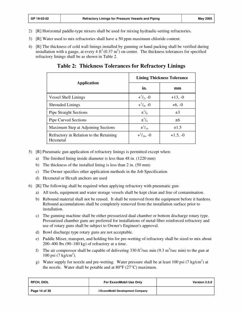
GP 19-03-02 Refractory Linings for Pressure Vessels and Piping May 2005
RFCH, DIOL For ExxonMobil Use Only Version 2.0.0
Page 14 of 39 ExxonMobil Development Company
2) [R] Horizontal paddle-type mixers shall be used for mixing hydraulic-setting refractories.
3) [R] Water used to mix refractories shall have a 50 ppm maximum chloride content.
4) [R] The thickness of cold wall linings installed by gunning or hand packing shall be verified during
installation with a gauge, at every 4 ft2(0.37 m
2) on center. The thickness tolerances for specified
refractory linings shall be as shown in Table 2.
Table 2: Thickness Tolerances for Refractory Linings
Lining Thickness Tolerance
Application
in. mm
Vessel Shell Linings +1/2, -0 +13, -0
Shrouded Linings +1/4, -0 +6, -0
Pipe Straight Sections ±1/8 ±3
Pipe Curved Sections ±1/4 ±6
Maximum Step at Adjoining Sections ±1/16 ±1.5
Refractory in Relation to the Retaining
Hexmetal
+1/16, -0 +1.5, -0
5) [R] Pneumatic gun application of refractory linings is permitted except when:
a) The finished lining inside diameter is less than 48 in. (1220 mm)
b) The thickness of the installed lining is less than 2 in. (50 mm)
c) The Owner specifies other application methods in the Job Specification
d) Hexmetal or Hexalt anchors are used
6) [R] The following shall be required when applying refractory with pneumatic gun:
a) All tools, equipment and water storage vessels shall be kept clean and free of contamination.
b) Rebound material shall not be reused. It shall be removed from the equipment before it hardens. Rebound accumulations shall be completely removed from the installation surface prior to
installation.
c) The gunning machine shall be either pressurized dual chamber or bottom discharge rotary type. Pressurized chamber guns are preferred for installations of metal fiber reinforced refractory and
use of rotary guns shall be subject to Owner's Engineer's approval.
d) Bowl discharge type rotary guns are not acceptable.
e) Paddle Mixer, transport, and holding bin for pre-wetting of refractory shall be sized to mix about
200–400 lbs (90–180 kg) of refractory at a time.
f) The air compressor shall be capable of delivering 330 ft3/sec min (9.3 m
3/sec min) to the gun at
100 psi (7 kg/cm2).
g) Water supply for nozzle and pre-wetting. Water pressure shall be at least 100 psi (7 kg/cm2) at
the nozzle. Water shall be potable and at 80 F (27 C) maximum.
GP 19-03-02 Refractory Linings for Pressure Vessels and Piping May 2005
RFCH, DIOL For ExxonMobil Use Only Version 2.0.0
Page 15 of 39 ExxonMobil Development Company
h) Nozzle and hosing with 11/4 or 1
1/2 in. ID (32 or 38 mm). The nozzle assembly shall provide for a
minimum of 16 in. (400 mm) extension between the water ring and the nozzle outlet to improve
the mixing of nozzle water with the castable and, thereby, more fully develop material properties, minimize rebounds, and prevent lamination defects.
i) Longitudinal joints of each course shall be at least 8 ft (2.4 m) long, and shall be staggered by at least 2 ft (0.6 m).
j) For down-hand work pieces (i.e., bottom heads of vertical vessels, piping, ductwork), the bottom 120 degrees of refractory shall be installed by casting prior to gunning the remaining section of
the lining. Hand packing of the bottom 120 degrees for other than thin-wall erosion resistant
lining shall be subject to Owner's Engineer's approval.
7) [R] The following requirements apply to vibration casting:
a) Vibrators shall be capable of delivering a total force equal to at least 100 percent of the total
weight being vibrated.
b) Proposals to vibrate forms or to use immersion vibrators shall be subject to Owner's Engineer's
approval.
c) The casting of pipe sections may be done in lengths up to 15 ft (4.5 m) maximum per casting.
Cold joints between casting are permitted provided refractory is allowed to cure for 24 hours
minimum before continuing the casting operation. The number of cold joints shall be minimized. Casting in bends shall be continuous and without joints. Sequential casting and welding of pipe
sections is permitted provided provisions regarding cold joints given above are followed.
8) [R] For cast installations, Installation Contractor shall check the concentricity and fit-up of the piping,
and notify Purchaser of any deviations. Use of mitering on curved sections shall be subject to
Owner's Engineer's approval. Styrofoam, if used, shall be 2 lb/ft3 (32 kg/m
3) minimum density. All
forms shall be removed after casting and curing. Burnout of forms shall not be permitted.
9) [R] All Type 2h chemical setting refractories shall be installed by placing slabs of pre-sliced material on top of the anchors and ramming them roughly perpendicular to the casing shell. Layered
application of refractory should be minimized to the greatest extent possible. Trimmings and loose rubble shall be discarded and not reused. Field water addition or re-mixing to recondition a refractory
with inadequate workability is unacceptable.
10) [R] The full thickness Type 2a/h shall be installed in a single application using a pneumatic bench
rammer or by hand packing and then hammering or pounding with a wood mallet or block to ensure that the Hexmetal cells are completely filled. Underfilling and voids shall not be permitted. The
material shall be cut back flush with the top of the Hexmetal so that the hex pattern is visible.
Maximum overfill of cells shall be 1/16 in. (1.5 mm).
11) [R] Special attention is required when hand packing refractory material in Flexible Hexmetal to
ensure that the refractory is completely packed under the wire and between the wire and the adjacent strip.
7. Repair of Linings
1) [R] Section 5 of this GP shall apply to the repair of lining systems, in addition to the requirements of
this Section.
GP 19-03-02 Refractory Linings for Pressure Vessels and Piping May 2005
RFCH, DIOL For ExxonMobil Use Only Version 2.0.0
Page 16 of 39 ExxonMobil Development Company
2) * [R] Owner's Engineer shall approve all repair procedures and plans before work commences.
3) * [R] Repairs of single layer linings by the overlay method are not permitted unless specifically
approved by the Owner's Engineer.
4) [R] Refractory repair in defective areas shall be as follows:
a) In the case of single layer linings, remove refractory to the shell and laterally to sound refractory.
The side of the cut shall be tapered back to provide patch retention (refer to Figure A–16). Replacement of lining metallic components may be necessary if damaged.
b) In the case of dual-layer linings, remove to the insulating castable. Removal of the insulating castable is not required unless damaged.
8. Curing and Dryout
8.1. Curing Procedures
[R] All linings shall be cured as follows before heating:
Types 1, 3–9 Moisten or seal for 24 hours minimum at 50–90 F (10–32 C).
Type 2a Air cured uncovered for 24 hours at ambient conditions of 50–90 F (10–32 C).Before heating, water contact is prohibited.
Type 2h Hold for 72 hours minimum at 50 F to 90 F (10 C to 32 C). Before heating, linings shall not be mechanically disturbed or come in contact with water.
8.2. Dryout/Heating Procedures
1) [R] All newly installed linings shall be dried out within 30 days of installation. Protection may be
required for longer periods, and shall be subject to Owner's Engineer's approval.
2) [R] When a metal shroud is required over the refractory, dryout of the refractory lining shall be completed prior to shroud installation.
3) [R] Procedures for heating/dryout of refractory linings shall be per Table 5 as applicable. If products
with Dryout Indices are used providing a potential opportunity for a faster dryout, that dryout
procedure shall be subject to the approval of the Owner's Engineer. When drying out multiple materials/installations at the same time, procedures may be merged using heating rates and holding
times for the lining material/design most sensitive to rapid dryout.
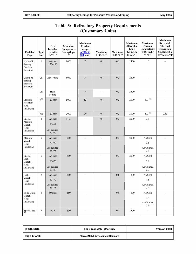
GP 19-03-02 Refractory Linings for Pressure Vessels and Piping May 2005
RFCH, DIOL For ExxonMobil Use Only Version 2.0.0
Page 17 of 39 ExxonMobil Development Company
Table 3: Refractory Property Requirements
(Customary Units)
Castable
Type
Type
No.
Dry
Installed
Density
lb/ft3 (1)
Minimum
Compressive
Strength psi (2)
Maximum
Erosion
Loss per
ASTM C
704 (cm3)
Maximum
PLC, % (3)
Maximum
PLC, % (4)
Maximum
Allowable
Long
Term Use
Temp. F
Maximum
Thermal
Conductivity
BTU in./hr
ft2
F(5)
Maximum
Reversible
Thermal
Expansion
Coefficient x
10–6
in./in.* F
Hydraulic
Setting
Erosion
Resistant
1 As cast
135–175
8000 7 -0.1 -0.3 2400 10 –
Chemical
Setting
Erosion
Resistant
2a Air-setting 8000 3 -0.1 -0.3 2600 – –
2h Heat-
setting
– 3 – -0.3 2600 – –
Erosion
Resistant
Heat
Insulating
3(9)
120 max 5000 12 -0.1 -0.3 2000 6.0 (7)
–
3lx 120 max 3000 20 -0.1 -0.3 2000 8.0 (7) 0.83
As cast
70–82
Special
Medium
Weight
Heat
Insulating
4
As gunned
70–90
1100 – -0.1 -0.3 2000 3.1 –
As cast As Cast
70–90 2.8
Medium
Weight
Heat
Insulating
5
As gunned
85–95
500 – – -0.3 2000
As Gunned
3.1
–
As cast As Cast
60–70 2.1
Special
Light
Weight
Heat
Insulating
6
As gunned
60–80
700 – – -0.3 2000
As Gunned
2.3
–
As cast As Cast
60–70 1.8
Light
Weight
Heat
Insulating
7
As gunned
65–75
300 – – -0.8 1800
As Gunned
2.4
–
As Cast
1.4
Extra Light
Weight
Heat
Insulating
8 60 max 150 – – -0.8 1800
As Gunned
2.0
–
Special Fill (6)
9 <35 100 – – -0.8 1500 – –

GP 19-03-02 Refractory Linings for Pressure Vessels and Piping May 2005
RFCH, DIOL For ExxonMobil Use Only Version 2.0.0
Page 18 of 39 ExxonMobil Development Company
Castable
Type
Type
No.
Dry
Installed
Density
lb/ft3 (1)
Minimum
Compressive
Strength psi (2)
Maximum
Erosion
Loss per
ASTM C
704 (cm3)
Maximum
PLC, % (3)
Maximum
PLC, % (4)
Maximum
Allowable
Long
Term Use
Temp. F
Maximum
Thermal
Conductivity
BTU in./hr
ft2 F (5)
Maximum
Reversible
Thermal
Expansion
Coefficient x
10–6 in./in.* F
Notes:
(1) In the installed condition after drying at 220 F for 18 hours (established by specimen and panel tests). For castable with metal fiber reinforcement the value shown for dry installed density shall be modified per the
following: Density (with fiber) = Density (without fiber) X 1.035.
(2) As determined by test procedures described in API RP 936.
(3) Permanent linear change (PLC) from cured to dried at 230°F.
(4) Permanent linear change (PLC) from dried at 230°F to fired at 1500°F.
(5) As per ASTM C 201 at mean temperature of 1000 F.
(6) Special mix of perlite and/or vermiculite and calcium aluminate cement.
(7) Same as Note 5 above, except that test data shall be taken from initial heat up curve with maximum 1350 F
hot face.
(8) Shaded areas indicate properties monitored during quality control.
(9) Type 3 to be used as equivalent to either of prior Type 3a or Type 3b designations.

GP 19-03-02 Refractory Linings for Pressure Vessels and Piping May 2005
RFCH, DIOL For ExxonMobil Use Only Version 2.0.0
Page 19 of 39 ExxonMobil Development Company
Table 4: Refractory Property Requirements
(Metric Units)
Castable
Type
Type
No.
Dry
Installed
Density
kg/m3 (1)
Minimum
Compressive
Strength
MPa (2)
Maximum
Erosion
Loss per
ASTM C
704 cm3
Maximum
PLC, % (3)
Maximum
PLC, % (4)
Maximum
Allowable Long
Term Use
Temp. C
Maximum
Thermal
Conductivity
W/M C(5)
Maximum
Reversible
Thermal
Expansion
Coefficient
x 10–6
m/m* C
Hydraulic
Setting
Erosion
Resistant
1 As cast
2160–2800
55 7 -0.1 -0.3 1375 1.55 –
Chemical
Setting
Erosion
Resistant
2a Air-setting 55 3 -0.1 -0.3 1425 – –
2h Heat-
setting
– 3 – -0.3 1425 – –
Erosion
Resistant
Heat
Insulating
3 (9) 1900 max 24.5 12 -0.1 -0.3 1095 0.93 (5) –
3lx 1900 max 20.7 20 -0.1 -0.3 1095 1.24 (5)
1.5
Special
Medium
Weight
Heat
Insulating
4 As cast
1120–1315
As gunned
1150–1440
7.6 – -0.1 -0.3 1095 0.45 –
As Cast
0.40
Medium
Weight
Heat
Insulating
5 As cast
1120–1440
As gunned
1360–1520
3.4 – – -0.3 1095
As Gunned
0.45
–
As Cast
0.30
Special
Light
Weight
Heat
Insulating
6 As cast
960–1120
As gunned
960–1280
4.8 – – -0.3 1095
As Gunned
0.33
–
As Cast
0.26
Light
Weight
Heat
Insulating
7 As cast
960–1120
As gunned
1040–1200
2.1 – – -0.8 962
As Gunned
0.35
–
As Cast
0.20
Extra
Light
Weight
Heat
Insulating
8 960 max 1 – – -0.8 962
As Gunned
0.29
–
Special
Fill(6)
9 <580 0.7 – – -0.8 815 – –
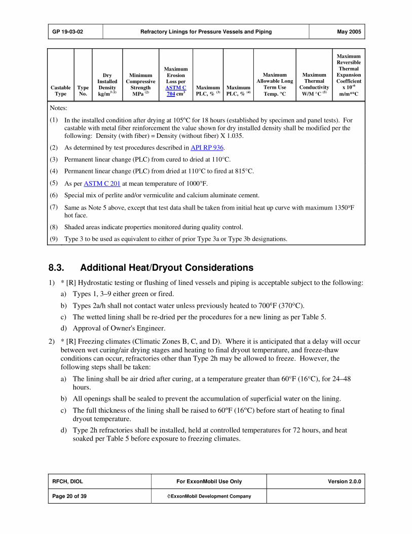
GP 19-03-02 Refractory Linings for Pressure Vessels and Piping May 2005
RFCH, DIOL For ExxonMobil Use Only Version 2.0.0
Page 20 of 39 ExxonMobil Development Company
Castable
Type
Type
No.
Dry
Installed
Density
kg/m3 (1)
Minimum
Compressive
Strength
MPa (2)
Maximum
Erosion
Loss per
ASTM C
704 cm3
Maximum
PLC, % (3)
Maximum
PLC, % (4)
Maximum
Allowable Long
Term Use
Temp. C
Maximum
Thermal
Conductivity
W/M C(5)
Maximum
Reversible
Thermal
Expansion
Coefficient
x 10–6
m/m* C
Notes:
(1) In the installed condition after drying at 105 C for 18 hours (established by specimen and panel tests). For
castable with metal fiber reinforcement the value shown for dry installed density shall be modified per the
following: Density (with fiber) = Density (without fiber) X 1.035.
(2) As determined by test procedures described in API RP 936.
(3) Permanent linear change (PLC) from cured to dried at 110°C.
(4) Permanent linear change (PLC) from dried at 110°C to fired at 815°C.
(5) As per ASTM C 201 at mean temperature of 1000 F.
(6) Special mix of perlite and/or vermiculite and calcium aluminate cement.
(7) Same as Note 5 above, except that test data shall be taken from initial heat up curve with maximum 1350 Fhot face.
(8) Shaded areas indicate properties monitored during quality control.
(9) Type 3 to be used as equivalent to either of prior Type 3a or Type 3b designations.
8.3. Additional Heat/Dryout Considerations
1) * [R] Hydrostatic testing or flushing of lined vessels and piping is acceptable subject to the following:
a) Types 1, 3–9 either green or fired.
b) Types 2a/h shall not contact water unless previously heated to 700 F (370 C).
c) The wetted lining shall be re-dried per the procedures for a new lining as per Table 5.
d) Approval of Owner's Engineer.
2) * [R] Freezing climates (Climatic Zones B, C, and D). Where it is anticipated that a delay will occur
between wet curing/air drying stages and heating to final dryout temperature, and freeze-thaw conditions can occur, refractories other than Type 2h may be allowed to freeze. However, the
following steps shall be taken:
a) The lining shall be air dried after curing, at a temperature greater than 60 F (16 C), for 24–48 hours.
b) All openings shall be sealed to prevent the accumulation of superficial water on the lining.
c) The full thickness of the lining shall be raised to 60 F (16 C) before start of heating to final dryout temperature.
d) Type 2h refractories shall be installed, held at controlled temperatures for 72 hours, and heat soaked per Table 5 before exposure to freezing climates.
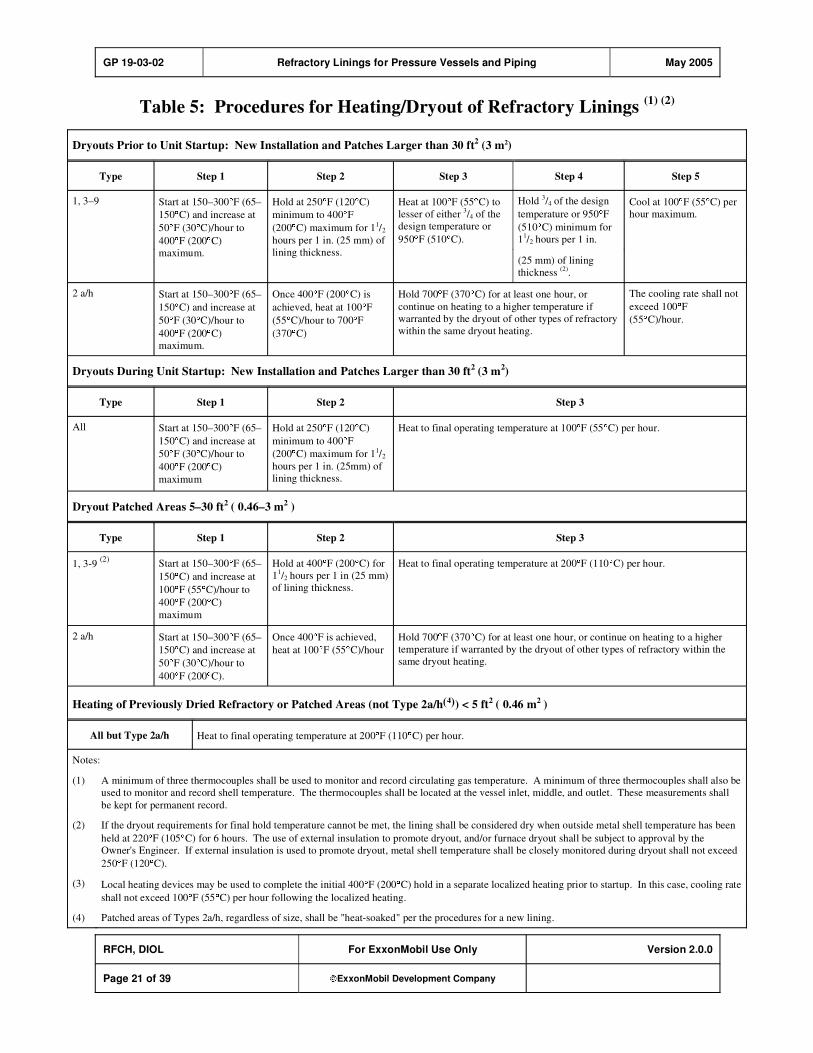
GP 19-03-02 Refractory Linings for Pressure Vessels and Piping May 2005
RFCH, DIOL For ExxonMobil Use Only Version 2.0.0
Page 21 of 39 ExxonMobil Development Company
Table 5: Procedures for Heating/Dryout of Refractory Linings (1) (2)
Dryouts Prior to Unit Startup: New Installation and Patches Larger than 30 ft2 (3 m2)
Type Step 1 Step 2 Step 3 Step 4 Step 5
Hold3/4 of the design
temperature or 950 F
(510 C) minimum for
11/2 hours per 1 in.
1, 3–9 Start at 150–300 F (65–
150 C) and increase at
50 F (30 C)/hour to
400 F (200 C)
maximum.
Hold at 250 F (120 C)
minimum to 400 F
(200 C) maximum for 11/2
hours per 1 in. (25 mm) of
lining thickness.
Heat at 100 F (55 C) to
lesser of either 3/4 of the
design temperature or
950 F (510 C).
(25 mm) of lining
thickness(2)
.
Cool at 100 F (55 C) per
hour maximum.
2 a/h Start at 150–300 F (65–
150 C) and increase at
50 F (30 C)/hour to
400 F (200 C)
maximum.
Once 400 F (200 C) is
achieved, heat at 100 F
(55 C)/hour to 700 F
(370 C)
Hold 700 F (370 C) for at least one hour, or
continue on heating to a higher temperature if
warranted by the dryout of other types of refractory
within the same dryout heating.
The cooling rate shall not
exceed 100 F
(55 C)/hour.
Dryouts During Unit Startup: New Installation and Patches Larger than 30 ft2 (3 m
2)
Type Step 1 Step 2 Step 3
All Start at 150–300 F (65–
150 C) and increase at
50 F (30 C)/hour to
400 F (200 C)
maximum
Hold at 250 F (120 C)
minimum to 400 F
(200 C) maximum for 11/2
hours per 1 in. (25mm) of
lining thickness.
Heat to final operating temperature at 100 F (55 C) per hour.
Dryout Patched Areas 5–30 ft2 ( 0.46–3 m2 )
Type Step 1 Step 2 Step 3
1, 3-9 (2)
Start at 150–300 F (65–
150 C) and increase at
100 F (55 C)/hour to
400 F (200 C)
maximum
Hold at 400 F (200 C) for
11/2 hours per 1 in (25 mm)
of lining thickness.
Heat to final operating temperature at 200 F (110 C) per hour.
2 a/h Start at 150–300 F (65–
150 C) and increase at
50 F (30 C)/hour to
400 F (200 C).
Once 400 F is achieved,
heat at 100 F (55 C)/hour
Hold 700 F (370 C) for at least one hour, or continue on heating to a higher
temperature if warranted by the dryout of other types of refractory within the
same dryout heating.
Heating of Previously Dried Refractory or Patched Areas (not Type 2a/h(4)) < 5 ft2 ( 0.46 m2 )
All but Type 2a/h Heat to final operating temperature at 200 F (110 C) per hour.
Notes:
(1) A minimum of three thermocouples shall be used to monitor and record circulating gas temperature. A minimum of three thermocouples shall also be
used to monitor and record shell temperature. The thermocouples shall be located at the vessel inlet, middle, and outlet. These measurements shall
be kept for permanent record.
(2) If the dryout requirements for final hold temperature cannot be met, the lining shall be considered dry when outside metal shell temperature has been
held at 220 F (105 C) for 6 hours. The use of external insulation to promote dryout, and/or furnace dryout shall be subject to approval by the
Owner's Engineer. If external insulation is used to promote dryout, metal shell temperature shall be closely monitored during dryout shall not exceed
250 F (120 C).
(3) Local heating devices may be used to complete the initial 400 F (200 C) hold in a separate localized heating prior to startup. In this case, cooling rate
shall not exceed 100 F (55 C) per hour following the localized heating.
(4) Patched areas of Types 2a/h, regardless of size, shall be "heat-soaked" per the procedures for a new lining.
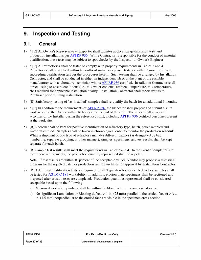
GP 19-03-02 Refractory Linings for Pressure Vessels and Piping May 2005
RFCH, DIOL For ExxonMobil Use Only Version 2.0.0
Page 22 of 39 ExxonMobil Development Company
9. Inspection and Testing
9.1. General
1) * [R] An Owner's Representative Inspector shall monitor application qualification tests and
production installations per API RP 936. While Contractor is responsible for the conduct of material qualification, these tests may be subject to spot checks by the Inspector or Owner's Engineer.
2) * [R] All refractories shall be tested to comply with property requirements in Tables 3 and 4.
Refractory shall be applied within 4 months of initial acceptance tests, or within 3 months of each
succeeding qualification test per the procedures herein. Such testing shall be arranged by Installation Contractor, and shall be conducted in either an independent lab or at the plant of the castable
manufacturer with a laboratory technician who is API RP 936 certified. Installation Contractor shall
direct testing to ensure conditions (i.e., mix water contents, ambient temperature, mix temperature, etc.) required for applicable installation quality. Installation Contractor shall report results to
Purchaser prior to lining installation.
3) [R] Satisfactory testing of "as-installed" samples shall re-qualify the batch for an additional 3 months.
4) * [R] In addition to the requirements of API RP 936, the Inspector shall prepare and submit a shift
work report to the Owner within 16 hours after the end of the shift. The report shall cover all activities of the Installer during the referenced shift, including API RP 936 certified personnel present
at the work site.
5) [R] Records shall be kept for positive identification of refractory type, batch, pallet sampled and water ratios used. Samples shall be taken in chronological order to monitor the production schedule.
When a shipment of one type of refractory includes different batches (as designated by bag
numbering, separate grouping, or other manner), samples, specimens, and test results shall be kept
separate for each batch.
6) [R] Sample test results shall meet the requirements in Tables 3 and 4. In the event a sample fails to meet these requirements, the production quantity represented shall be rejected.
Note: If test results are within 10 percent of the acceptable values, Vendor may propose a re-testing
program for the rejected batch or production run to Purchaser for approval by Installation Contractor.
7) [R] Additional qualification tests are required for all Type 2h refractories. Refractory samples shall
be tested for ASTM C 181 workability. In addition, erosion plate specimens shall be sectioned and
inspected after erosion tests are completed. Production quantities represented shall be considered acceptable based upon the following:
a) Measured workability indices shall be within the Manufacturer recommended range.
b) No significant Lamination or Bloating defects > 1 in. (25 mm) parallel to the eroded face or > 1/16
in. (1.5 mm) perpendicular to the eroded face are visible in the specimen cross-section.
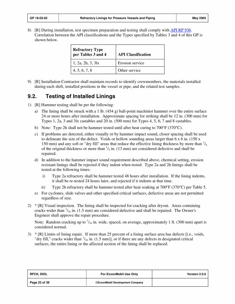
GP 19-03-02 Refractory Linings for Pressure Vessels and Piping May 2005
RFCH, DIOL For ExxonMobil Use Only Version 2.0.0
Page 23 of 39 ExxonMobil Development Company
8) [R] During installation, test specimen preparation and testing shall comply with API RP 936.
Correlation between the API classifications and the Types specified by Tables 3 and 4 of this GP is
shown below.
Refractory Type
per Tables 3 and 4 API Classification
1, 2a, 2h, 3, 3lx Erosion service
4, 5, 6, 7, 8 Other service
9) [R] Installation Contractor shall maintain records to identify crewmembers, the materials installed
during each shift, installed positions in the vessel or pipe, and the related test samples.
9.2. Testing of Installed Linings
1) [R] Hammer testing shall be per the following:
a) The lining shall be struck with a 1 lb. (454 g) ball-point machinist hammer over the entire surface
24 or more hours after installation. Approximate spacing for striking shall be 12 in. (300 mm) for
Types 1, 2a, 3 and 3lx castables and 20 in. (500 mm) for Types 4, 5, 6, 7 and 8 castables.
b) Note: Type 2h shall not be hammer tested until after heat curing to 700 F (370 C).
c) If problems are detected, either visually or by hammer impact sound, closer spacing shall be used
to delineate the size of the defect. Voids or hollow sounding areas larger than 6 x 6 in. (150 x
150 mm) and any soft or "dry fill" areas that reduce the effective lining thickness by more than 1/4
of the original thickness or more than 1/2 in. (13 mm) are considered defective and shall be
repaired.
d) In addition to the hammer impact sound requirement described above, chemical setting, erosion
resistant linings shall be rejected if they indent when tested. Type 2a and 2h linings shall be tested at the following times:
i) Type 2a refractory shall be hammer tested 48 hours after installation. If the lining indents,
it shall be re-tested 24 hours later, and rejected if it indents at that time.
ii) Type 2h refractory shall be hammer tested after heat soaking at 700 F (370 C) per Table 5.
e) For cyclones, slide valves and other specified critical surfaces, defective areas are not permitted
regardless of size.
2) * [R] Visual inspection. The lining shall be inspected for cracking after dryout. Areas containing
cracks wider than 1/16 in. (1.5 mm) are considered defective and shall be repaired. The Owner's
Engineer shall approve the repair procedure.
Note: Random cracking up to 1/16 in. wide, spaced, on average, approximately 1 ft. (300 mm) apart is
considered normal.
3) * [R] Limits of lining repair. If more than 25 percent of a lining surface area has defects [i.e., voids, "dry fill," cracks wider than
1/16 in. (1.5 mm)], or if there are any defects in designated critical
surfaces, the entire lining or the affected section of the lining shall be replaced.

GP 19-03-02 Refractory Linings for Pressure Vessels and Piping May 2005
RFCH, DIOL For ExxonMobil Use Only Version 2.0.0
Page 24 of 39 ExxonMobil Development Company
Appendix: Design and Installation of Lining Details
This Appendix details the design and installation of linings as shown on the following drawings. The
acceptable metric equivalents for Figures A–1 through A–16 are shown in Table A–1.
Table A–1: Acceptable Metric Equivalents
Metal Thickness
Stud or Round Bar,
Diameter
Other Linear
in. mm in. mm in. mm in. mm
1/8 3
3/16 5
1/32 1 1
7/8 50
1/4 6 1/4 6 1/16 1.5 2 50
3/8 10 1/2 12 1/8 3 3 75
1/2 12 – –
3/16 5 4 100
– – – – 7/32 5.5 5 125
– – – – 1/4 6 5
1/2 140
– – – – 3/8 10 8 200
– – – – 1/2 13 81/2 215
– – – – 5/8 16 91/2 240
– – – – 3/4 19 10 250
– – – – 1 25 30 750
– – – – 11/2 38 60 1500
– – – – D, in. (25) x in. = mm
– – – – 65 in.2 400 cm2
– – – – 1 ft2 0.09 m2
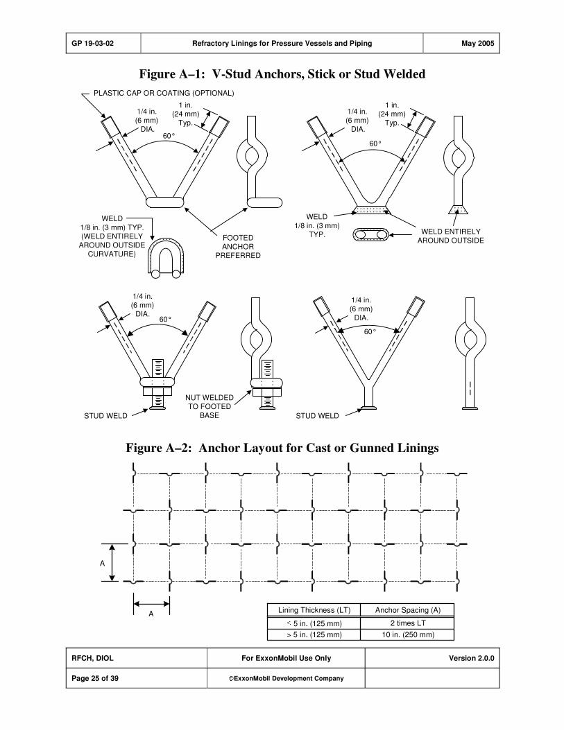
GP 19-03-02 Refractory Linings for Pressure Vessels and Piping May 2005
RFCH, DIOL For ExxonMobil Use Only Version 2.0.0
Page 25 of 39 ExxonMobil Development Company
Figure A–1: V-Stud Anchors, Stick or Stud Welded
PLASTIC CAP OR COATING (OPTIONAL)
60°
1 in.
(24 mm)
Typ.
1/4 in.
(6 mm)
DIA.
WELD
1/8 in. (3 mm) TYP.
(WELD ENTIRELY
AROUND OUTSIDE
CURVATURE)
FOOTED
ANCHOR
PREFERRED
60°
1/4 in.
(6 mm)
DIA.
STUD WELD
NUT WELDED
TO FOOTED
BASE
60°
1/4 in.
(6 mm)
DIA.
STUD WELD
60°
1 in.
(24 mm)
Typ.
1/4 in.
(6 mm)
DIA.
WELD
1/8 in. (3 mm)
TYP. WELD ENTIRELY
AROUND OUTSIDE
Figure A–2: Anchor Layout for Cast or Gunned Linings
A
A
Lining Thickness (LT) Anchor Spacing (A)
5 in. (125 mm) 2 times LT
> 5 in. (125 mm) 10 in. (250 mm)
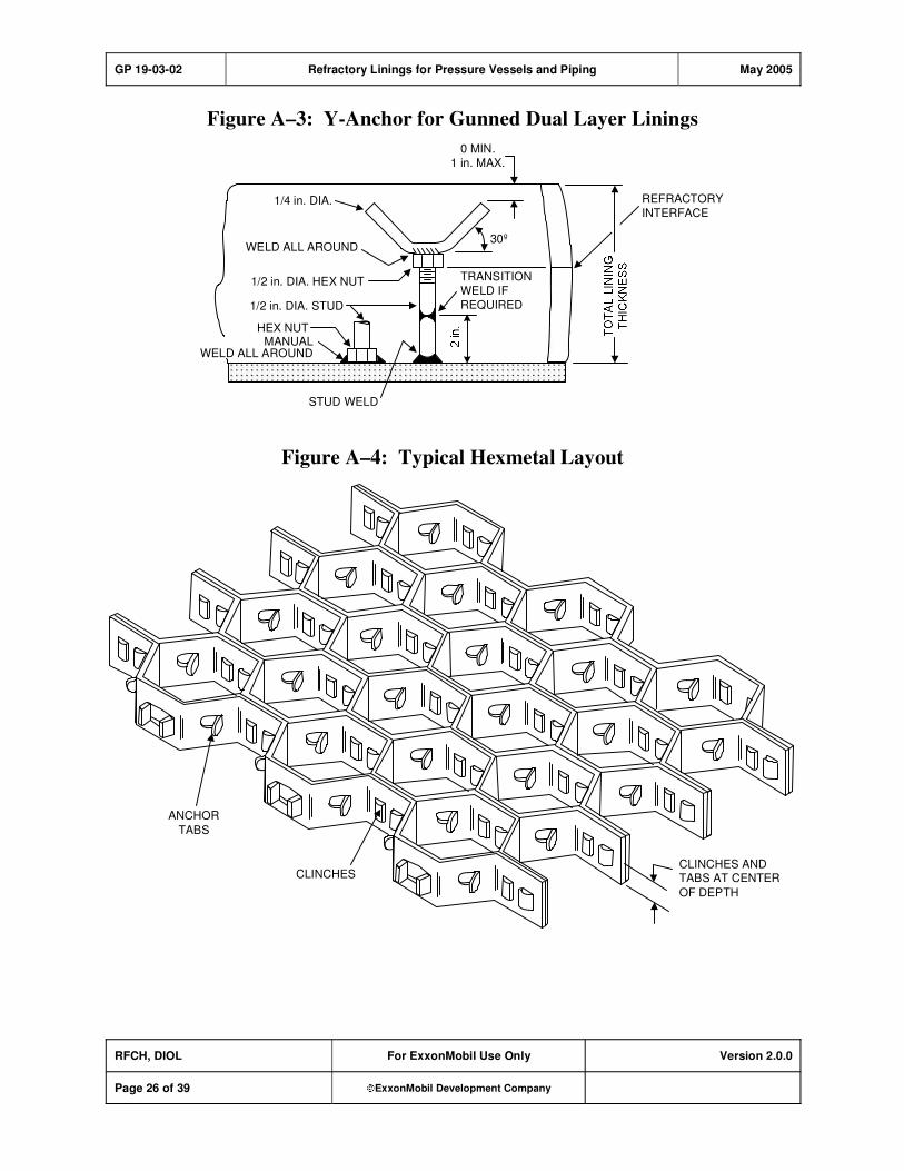
GP 19-03-02 Refractory Linings for Pressure Vessels and Piping May 2005
RFCH, DIOL For ExxonMobil Use Only Version 2.0.0
Page 26 of 39 ExxonMobil Development Company
Figure A–3: Y-Anchor for Gunned Dual Layer Linings
STUD WELD
MANUALWELD ALL AROUND
HEX NUT
1/2 in. DIA. STUD
WELD ALL AROUND
1/4 in. DIA.
1/2 in. DIA. HEX NUT TRANSITION
WELD IF
REQUIRED
30º
0 MIN.
1 in. MAX.
REFRACTORY
INTERFACE
Figure A–4: Typical Hexmetal Layout
CLINCHES ANDTABS AT CENTER
OF DEPTH
ANCHOR
TABS
CLINCHES

GP 19-03-02 Refractory Linings for Pressure Vessels and Piping May 2005
RFCH, DIOL For ExxonMobil Use Only Version 2.0.0
Page 27 of 39 ExxonMobil Development Company
Figure A–5: Hexmetal Welding Including Termination
Strips for Hexmetal Welded Directly to Plate
HEXMESH
1/8 in.(3 mm)
1/2 in.
(13 mm)
1/2 in.
(13 mm)
1/8 in. (3 mm) THICK
TERMINATIONSTRIPS (NOTE 2)
WELDS 1/8 in.(3 mm) TYPICAL
TYPICAL
NOTES:(1) Hexmetal to be welded to backing plate with approximately 21 welds per ft 2 in pattern shown or equivalent layout yielding
the same number and length of welds per unit area of hexmetal.
(2) Termination strips shall be welded continuously to backing plate with a typical 1/8 in. (3 mm) weld on one side.
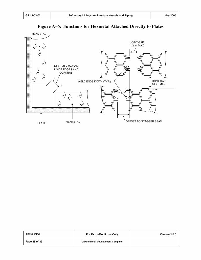
GP 19-03-02 Refractory Linings for Pressure Vessels and Piping May 2005
RFCH, DIOL For ExxonMobil Use Only Version 2.0.0
Page 28 of 39 ExxonMobil Development Company
Figure A–6: Junctions for Hexmetal Attached Directly to Plates
JOINT GAP:
1/2 in. MAX.
HEXMETAL
1/2 in. MAX GAP ON
INSIDE EDGES AND
CORNERS
PLATE
WELD ENDS DOWN (TYP.)
OFFSET TO STAGGER SEAM
JOINT GAP:
1/2 in. MAX.
HEXMETAL
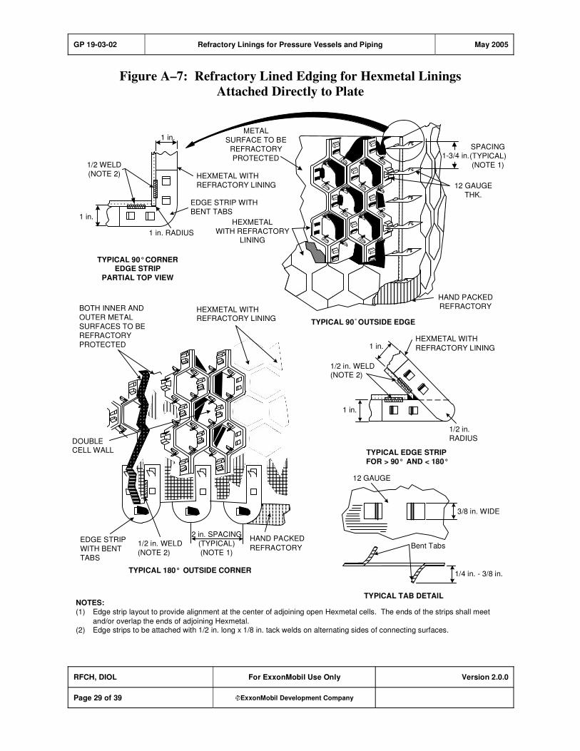
GP 19-03-02 Refractory Linings for Pressure Vessels and Piping May 2005
RFCH, DIOL For ExxonMobil Use Only Version 2.0.0
Page 29 of 39 ExxonMobil Development Company
Figure A–7: Refractory Lined Edging for Hexmetal Linings
Attached Directly to Plate
1-3/4 in.
TYPICAL 90° OUTSIDE EDGE
1 in.
1/2 WELD
(NOTE 2)
1 in.
HEXMETAL WITH
REFRACTORY LINING
EDGE STRIP WITH
BENT TABS
1 in. RADIUS
TYPICAL 90° CORNEREDGE STRIP
PARTIAL TOP VIEW
METAL
SURFACE TO BE
REFRACTORY
PROTECTED
HEXMETAL
WITH REFRACTORYLINING
HAND PACKED
REFRACTORY
SPACING
(TYPICAL)
(NOTE 1)
12 GAUGE
THK.
1 in.HEXMETAL WITH
REFRACTORY LINING
1/2 in.
RADIUS
1/2 in. WELD(NOTE 2)
TYPICAL EDGE STRIP
FOR > 90° AND < 180°
12 GAUGE
3/8 in. WIDE
Bent Tabs
1/4 in. - 3/8 in.
TYPICAL TAB DETAIL
BOTH INNER AND
OUTER METAL
SURFACES TO BE
REFRACTORY
PROTECTED
HEXMETAL WITHREFRACTORY LINING
DOUBLECELL WALL
EDGE STRIP
WITH BENT
TABS
1/2 in. WELD
(NOTE 2)
2 in. SPACING
(TYPICAL)
(NOTE 1)
HAND PACKED
REFRACTORY
TYPICAL 180° OUTSIDE CORNER
NOTES:
(1) Edge strip layout to provide alignment at the center of adjoining open Hexmetal cells. The ends of the strips shall meet
and/or overlap the ends of adjoining Hexmetal.(2) Edge strips to be attached with 1/2 in. long x 1/8 in. tack welds on alternating sides of connecting surfaces.
1 in.
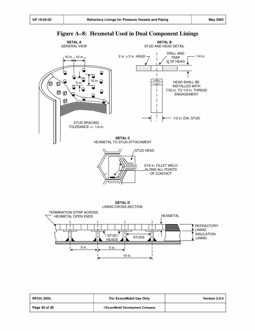
GP 19-03-02 Refractory Linings for Pressure Vessels and Piping May 2005
RFCH, DIOL For ExxonMobil Use Only Version 2.0.0
Page 30 of 39 ExxonMobil Development Company
Figure A–8: Hexmetal Used in Dual Component Linings
1/2 in. DIA. STUD
3/16 in. FILLET WELDALONG ALL POINTS
OF CONTACT
HEAD SHALL BEINSTALLED WITH
7/32 in. TO 1/4 in. THREADENGAGEMENT
2 in. x 2 in. HEAD
STUD SPACING
TOLERANCE +/- 1/4 in.
1/4 in.10 in. 10 in.
STUD HEAD
HEXMETALTERMINATION STRIP ACROSS
HEXMETAL OPEN ENDS
STUDSSTUD
HEADS
10 in.
5 in. 5 in.
REFRACTORYLINING
INSULATIONLINING
DETAL AGENERAL VIEW
DETAL BSTUD AND HEAD DETAIL
DETAL CHEXMETAL TO STUD ATTACHMENT
DETAL D
LINING CROSS-SECTION
5 in.10 in.
DRILL AND
TRAPC OF HEADL

GP 19-03-02 Refractory Linings for Pressure Vessels and Piping May 2005
RFCH, DIOL For ExxonMobil Use Only Version 2.0.0
Page 31 of 39 ExxonMobil Development Company
Figure A–9: Typical Junctions for Hexmetal Attached to Studs
FILLET WELD FULL DEPTH
AT EACH CONTACT POINT
FILLET WELD
FULL DEPTH
AT EACH
CONTACT
POINT
NOTE: All welds are 1/8 in. (3 mm) fillets along full thickness of Hexmetal
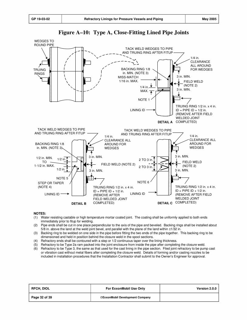
GP 19-03-02 Refractory Linings for Pressure Vessels and Piping May 2005
RFCH, DIOL For ExxonMobil Use Only Version 2.0.0
Page 32 of 39 ExxonMobil Development Company
Figure A–10: Type A, Close-Fitting Lined Pipe Joints
WEDGES TO
ROUND PIPE
TRUING
RINGS
TACK WELD WEDGES TO PIPE
AND TRUING RING AFTER FITUP
TRUING RING 1/2 in. x 4 in.
ID = PIPE ID + 1/2 in.
(REMOVE AFTER FIELD
WELDED JOINT
COMPLETED)
1/4 in.
CLEARANCE
ALL AROUND
FOR WEDGES
FIELD WELD
(NOTE 2)
LINING ID
MISS-MATCH
1/16 in. MAX.
NOTE 1
1/4 in.
MAX.
TACK WELD WEDGES TO PIPEAND TRUING RING AFTER FITUP
TACK WELD WEDGES TO PIPE
AND TRUING RING AFTER FITUP1/4 in.
CLEARANCE ALL
AROUND FOR
WEDGES
FIELD WELD (NOTE 2)
LINING ID
FIELD WELD
(NOTE 2)
NOTE 5
NOTE 6
LINING ID
DETAIL A
DETAIL B DETAIL C
1/2 in. MIN.
TO1-1/2 in. MAX.
1/2 in.
1/2 in.
STEP OR TAPER
(NOTE 4)
BACKING RING 1/8
in. MIN. (NOTE 3)
3 in. MIN.
2 TO 3 in.
2 TO 3 in.
3 in. MIN.
NOTES:(1) Water resisting castable or high temperature mortar coated joint. The coating shall be uniformly applied to both ends
immediately prior to fitup for welding.(2) Pipe ends shall be cut in one place perpendicular to the axis of the pipe and beveled. Backing rings shall be installed about
5/8 in. above the land at the weld joint bevel, and parallel with the plane of the land within ±1/32 in.
(3) Backing ring to be welded on one side in the pipe before fitting the two ends of the pipe together. This backing ring to bedimensioned and held in position behind the closure weld in the spool sections.
(4) Refractory ends shall be contoured with a step or 1/2 continuous taper over the lining thickness.(5) Refractory to be Type 2a ram packed into the joint enclosure from inside the pipe after completing the closure weld.(6) Refractory to be Type 3, the same as that used for the cast lining in the pipe section. Filed joint refractory to be pump cast
or vibration cast without metal fibers after completing the closure weld. Details of forming and/or casting nozzles to beincluded in installation procedures that the Installation Contractor shall submit to the Owner’s Engineer for approval.
3 in. MIN.
3 in. MIN.
TRUING RING 1/2 in. x 4 in.
ID = PIPE ID + 1/2 in.
(REMOVE AFTER
FIELD WELDED JOINT
COMPLETED)
3 in. MIN.
3 in. MIN.
1/4 in.
CLEARANCE ALL
AROUND FOR
WEDGES
TRUING RING 1/2 in. x 4 in.
ID = PIPE ID + 1/2 in.
(REMOVE AFTER FIELD
WELDED JOINT
COMPLETED)
BACKING RING 1/8
in. MIN. (NOTE 3)
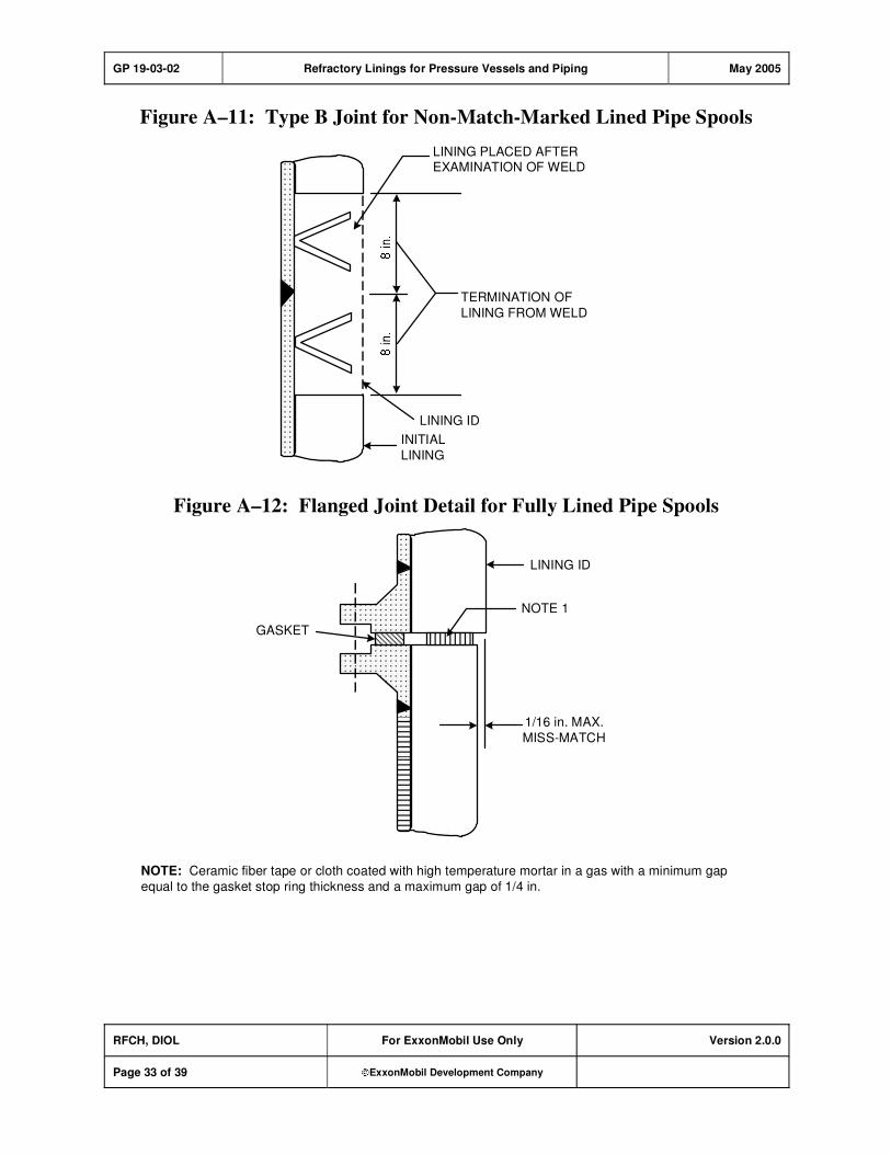
GP 19-03-02 Refractory Linings for Pressure Vessels and Piping May 2005
RFCH, DIOL For ExxonMobil Use Only Version 2.0.0
Page 33 of 39 ExxonMobil Development Company
Figure A–11: Type B Joint for Non-Match-Marked Lined Pipe Spools
LINING PLACED AFTEREXAMINATION OF WELD
TERMINATION OF
LINING FROM WELD
INITIAL
LINING
LINING ID
Figure A–12: Flanged Joint Detail for Fully Lined Pipe Spools
GASKET
1/16 in. MAX.
MISS-MATCH
LINING ID
NOTE 1
NOTE: Ceramic fiber tape or cloth coated with high temperature mortar in a gas with a minimum gap
equal to the gasket stop ring thickness and a maximum gap of 1/4 in.
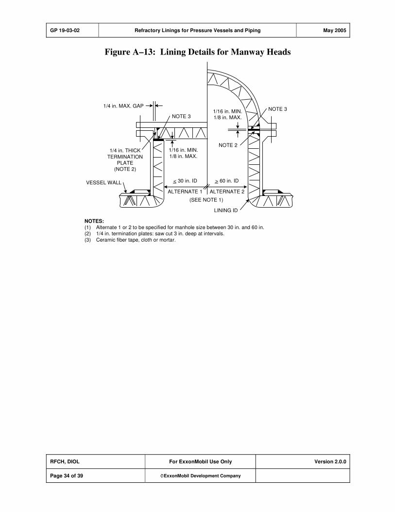
GP 19-03-02 Refractory Linings for Pressure Vessels and Piping May 2005
RFCH, DIOL For ExxonMobil Use Only Version 2.0.0
Page 34 of 39 ExxonMobil Development Company
Figure A–13: Lining Details for Manway Heads
> 60 in. ID< 30 in. ID
NOTE 2
NOTE 3
VESSEL WALL
LINING ID
(SEE NOTE 1)
1/4 in. THICK
TERMINATIONPLATE
(NOTE 2)
1/16 in. MIN.1/8 in. MAX.
1/16 in. MIN.
1/8 in. MAX.
ALTERNATE 1 ALTERNATE 2
1/4 in. MAX. GAPNOTE 3
NOTES:
(1) Alternate 1 or 2 to be specified for manhole size between 30 in. and 60 in.
(2) 1/4 in. termination plates: saw cut 3 in. deep at intervals.
(3) Ceramic fiber tape, cloth or mortar.
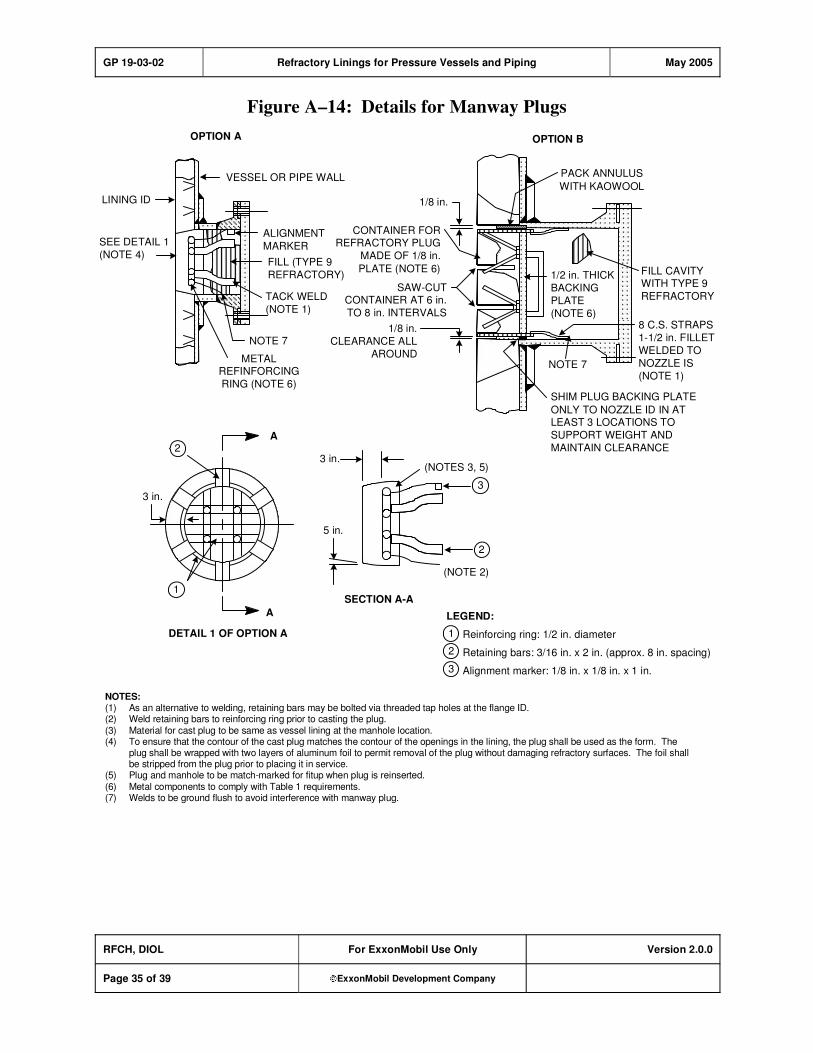
GP 19-03-02 Refractory Linings for Pressure Vessels and Piping May 2005
RFCH, DIOL For ExxonMobil Use Only Version 2.0.0
Page 35 of 39 ExxonMobil Development Company
Figure A–14: Details for Manway Plugs
Reinforcing ring: 1/2 in. diameter
Retaining bars: 3/16 in. x 2 in. (approx. 8 in. spacing)
Alignment marker: 1/8 in. x 1/8 in. x 1 in.
LEGEND:
NOTE 7
METALREFINFORCING
RING (NOTE 6)
LINING ID
SEE DETAIL 1
(NOTE 4)FILL (TYPE 9
REFRACTORY)
TACK WELD
(NOTE 1)
ALIGNMENT
MARKER
VESSEL OR PIPE WALL
OPTION A
1/8 in.
CLEARANCE ALL
AROUND
SAW-CUTCONTAINER AT 6 in.
TO 8 in. INTERVALS
1/8 in.
CONTAINER FORREFRACTORY PLUG
MADE OF 1/8 in.
PLATE (NOTE 6) FILL CAVITYWITH TYPE 9
REFRACTORY
PACK ANNULUS
WITH KAOWOOL
1/2 in. THICK
BACKING
PLATE
(NOTE 6)
NOTE 7
8 C.S. STRAPS
1-1/2 in. FILLET
WELDED TO
NOZZLE IS
(NOTE 1)
SHIM PLUG BACKING PLATE
ONLY TO NOZZLE ID IN ATLEAST 3 LOCATIONS TO
SUPPORT WEIGHT AND
MAINTAIN CLEARANCE
OPTION B
(NOTES 3, 5)
(NOTE 2)
3 in.
5 in.
SECTION A-A
3 in.
A
A
DETAIL 1 OF OPTION A
NOTES:(1) As an alternative to welding, retaining bars may be bolted via threaded tap holes at the flange ID.(2) Weld retaining bars to reinforcing ring prior to casting the plug.(3) Material for cast plug to be same as vessel lining at the manhole location.(4) To ensure that the contour of the cast plug matches the contour of the openings in the lining, the plug shall be used as the form. The
plug shall be wrapped with two layers of aluminum foil to permit removal of the plug without damaging refractory surfaces. The foil shallbe stripped from the plug prior to placing it in service.
(5) Plug and manhole to be match-marked for fitup when plug is reinserted.(6) Metal components to comply with Table 1 requirements.(7) Welds to be ground flush to avoid interference with manway plug.
1
2
3
2
3
1
2
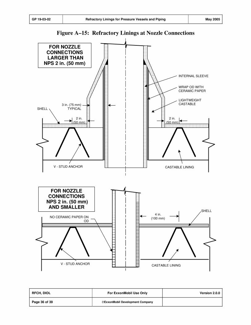
GP 19-03-02 Refractory Linings for Pressure Vessels and Piping May 2005
RFCH, DIOL For ExxonMobil Use Only Version 2.0.0
Page 36 of 39 ExxonMobil Development Company
Figure A–15: Refractory Linings at Nozzle Connections
SHELL
2 in.
(50 mm)
3 in. (75 mm)
TYPICALSHELL
2 in.
(50 mm)
LIGHTWEIGHTCASTABLE
CASTABLE LINING
INTERNAL SLEEVE
FOR NOZZLECONNECTIONS LARGER THAN
NPS 2 in. (50 mm)
WRAP OD WITHCERAMIC PAPER
V - STUD ANCHOR
FOR NOZZLECONNECTIONS
NPS 2 in. (50 mm)AND SMALLER
4 in.
(100 mm)
V - STUD ANCHORCASTABLE LINING
NO CERAMIC PAPER ON
OD
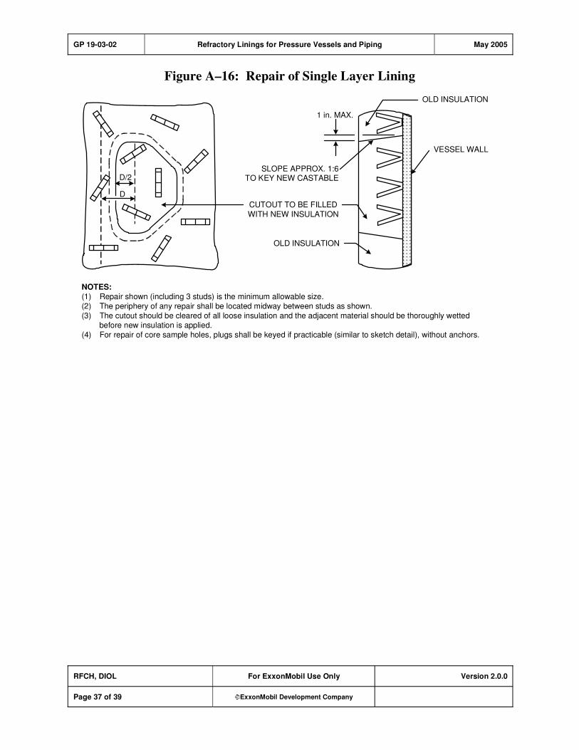
GP 19-03-02 Refractory Linings for Pressure Vessels and Piping May 2005
RFCH, DIOL For ExxonMobil Use Only Version 2.0.0
Page 37 of 39 ExxonMobil Development Company
Figure A–16: Repair of Single Layer Lining
SLOPE APPROX. 1:6TO KEY NEW CASTABLE
CUTOUT TO BE FILLEDWITH NEW INSULATION
VESSEL WALL
OLD INSULATION
1 in. MAX.
OLD INSULATION
D/2
D
NOTES:(1) Repair shown (including 3 studs) is the minimum allowable size.(2) The periphery of any repair shall be located midway between studs as shown.(3) The cutout should be cleared of all loose insulation and the adjacent material should be thoroughly wetted
before new insulation is applied.(4) For repair of core sample holes, plugs shall be keyed if practicable (similar to sketch detail), without anchors.

GP 19-03-02 Refractory Linings for Pressure Vessels and Piping May 2005
RFCH, DIOL For ExxonMobil Use Only Version 2.0.0
Page 38 of 39 ExxonMobil Development Company
Record of Change
Version 1.0.0 Date: 03/02
Location Action Description
Initial Publish.
Version 1.0.0 Date: 07/03
Global Practice version number and format updated to comply with new
process; however, original publish date remains, and no content was
modified.
Version 2.0.0 Date: 05/05
Section 1.7 Addition API RP 936 certification requirement for specified service providers.
Section 3, Item
(2a)
Modification "... Dryout Index (as defined in API RP 936) of products being installed,"
Section 3, Item
(2b)
Addition b) List of API RP 936 personnel.
Section 8.2,
Item (3)
Modification "... For products with Dryout Indices are used providing a potential
opportunity for a faster, that dryout procedure shall be subject to the
approval of the owner's engineer."
Table 3 &
Table 4
Modification For Types 2a and 2h, Maximum Erosion Loss per ASTM C 704 (cm3)
changed from 4 to 3 cc.
Section 9.1,
Item (2)
Modification "... manufacturer with a laboratory technician who is API 936 certified."
Section 9.1,
Item (4)
Modification "... including API 936 certified personnel present at the work site."
Figure A-1 Modification Added alternate designs for v-stud anchors.
Figure A-15 Modification Two separate drawings for nozzles >2" and <2" to replace confusing split
drawing.

GP 19-03-02 Refractory Linings for Pressure Vessels and Piping May 2005
RFCH, DIOL For ExxonMobil Use Only Version 2.0.0
Page 39 of 39 ExxonMobil Development Company
Attachment: Purpose Codes Definitions
Code Description
C Assigned to paragraphs containing specifications whose primary purpose is reduced costs.
Reduced cost in this context refers to initial investment cost and does not include Life-Cycle
cost considerations. Life-Cycle cost considerations are captured under reliability,
maintainability, or operability purpose codes.
E Assigned to paragraphs containing specifications whose primary purpose is driven by
environmental considerations. Environmental considerations typically include specifications
intended to protect against emissions/leakage to the air, water, and/or soil. Deviations from the specifications contained in such paragraphs require formal review and approval according to
local environmental policy.
I Assigned to paragraphs that provide only clarifying information such as Scope statements,
definitions of terms, etc.
M Assigned to paragraphs containing specifications whose primary purpose is to provide for
maintainability of equipment or systems. Maintainability provisions are those that facilitate the
performance of maintenance on equipment/systems either during downtimes or during on-
stream operations.
O Assigned to paragraphs containing specifications whose primary purpose is to assure
operability of equipment or systems. Operability is the ability of the equipment/system to
perform satisfactorily even though conditions are off-design, such as during startups, process swings, subcomponent malfunction, etc.
R Assigned to paragraphs containing specifications whose primary purpose is to improve or
assure the reliability of equipment or systems. Reliability is a measure of the ability of
equipment/systems to operate without malfunction or failure between planned maintenance interventions.
S Assigned to paragraphs containing specifications whose primary purpose is avoidance of
personnel or operational safety incidents. Any deviation from the specifications contained in
such designated paragraphs requires formal review and approval according to local safety policy.
Personnel Safety: Refers to the avoidance of recordable personnel injuries; i.e., burns, cuts,
abrasions, inhalation, or exposure to dangerous substances, etc., that could result in medical treatment, restricted work, lost-time incidents, or
fatalities.
Operational
Safety:
Refers to the prevention and control of process releases, fires, explosions,
etc.

GP 20-01-01 Inspection of Equipment and Materials November 2008
Refining/Chemicals, Downstream Imperial Oil
For Company Use Only Version 2.1.0
Page 1 of 19 ExxonMobil Development Company
Copyright Waiver ExxonMobil Development Company and ExxonMobil Pipeline Company hereby license the use of ExxonMobil Engineering Practices System (EMEPS) Global Practices (GPs) for use by any ExxonMobil division, subsidiary, or more-than-50%-owned affiliate. The GPs may be downloaded and modified as necessary for project and affiliate use. Written permission from ExxonMobil Development Company or ExxonMobil Pipeline Company is not required. However, any modified GPs must be renumbered to a project-specific or affiliate-specific number to distinguish them from the GPs on the EMEPS web site. ExxonMobil operated joint ventures may utilize GPs to create project-specific or location-specific specifications. It is the responsibility of individual affiliate or joint venture to ensure that the use of GPs and their derivatives is limited to joint venture related business and not disclosed or used outside the JV without appropriate EM management approval.
Inspection of Equipment and Materials
GP 20-01-01
Scope
1) [I] This Global Practice (GP) lists equipment and materials for which the Company requires inspection by a Company Inspector or an appointed Owner's Representative, and this GP defines
requirements relating to the inspection activities of this equipment and material.
2) [I] This GP shall be applied to any direct or indirect purchase orders or suborders issued on behalf of, or by, the Company.
GP 20-01-01 Inspection of Equipment and Materials November 2008
RFCH, DIOL For Company Use Only Version 2.1.0
Page 2 of 19 ExxonMobil Development Company
Table of Contents
1. Required References ............................................................................................ 3
1.1. Global Practices–ExxonMobil Engineering Practices ................................... 3
1.2. EMRE–ExxonMobil Research and Engineering ........................................... 3
2. Additional Requirements...................................................................................... 3
3. Definitions.............................................................................................................. 4
4. Inspection Activities and Data Requirements .................................................... 4
5. Supplier/Subsupplier Obligations and Responsibilities.................................... 5
Record of Change ....................................................................................................... 17
Attachment: Purpose Code Definitions.................................................................... 19

GP 20-01-01 Inspection of Equipment and Materials November 2008
RFCH, DIOL For Company Use Only Version 2.1.0
Page 3 of 19 ExxonMobil Development Company
1. Required References
This section lists the Practices, codes, standards, specifications, and publications that shall be used with this document. Unless otherwise specified herein, use the latest edition.
1.1. Global Practices–ExxonMobil Engineering Practices
GP 20-01-02 Administrative Procedures for Obtaining Inspection
GP 20-01-03 Quality Programs
1.2. EMRE–ExxonMobil Research and Engineering
Equipment Criticality
Rating Process
EMRE Projects Equipment Criticality Work Process
2. Additional Requirements
1) [*] [I] [R] Table 1 of this GP lists equipment and materials that require inspection by the Company
Inspector or Designated Representative unless specifically waived by the Owner.
2) [I] The following modifications to the requirements of this GP will be specified in the purchase order:
a) Specific Owner requirements
b) Compliance with local rules and regulations
c) Additions or deletions to Table 1
Note: This does not preclude the Inspector from inspecting material or equipment component parts
that are utilized in fabrication/assembly of equipment and materials in Table 1.
3) [I] [R] Inspection and test requirements shall include, but not be limited to, those contained in the purchase order.
4) This GP makes reference to equipment and material that would require subsequent reference to a
large number of additional GPs. To make this GP more efficient, a rationalized listing of all possible GPs will not be provided here. Alternatively, a link to the ExxonMobil Engineering Practices
System (EMEPS) is provided for the user's convenience.
5) While every effort has been made to provide a link to the applicable GPs in Table 1 of this GP, users
are encouraged to reference the specific GP covering the equipment and material in consideration.
6) [A] [R] Engineered equipment listed in Table 1 of this GP shall be assigned a Criticality Rating in accordance with EMRE Projects Equipment Criticality Work Process or equivalent as approved by
the Owner's Engineer.
7) GP 20-01-02 covers the administrative process for securing inspection of equipment and material
listed in Table 1 of this GP.
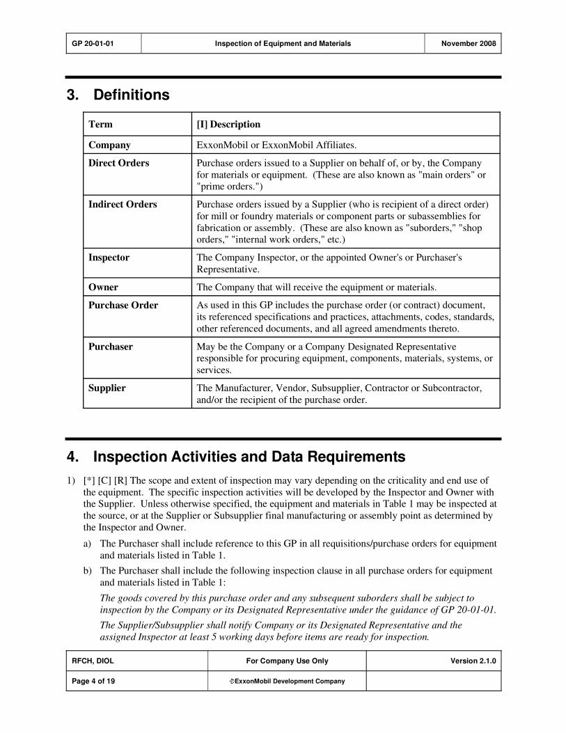
GP 20-01-01 Inspection of Equipment and Materials November 2008
RFCH, DIOL For Company Use Only Version 2.1.0
Page 4 of 19 ExxonMobil Development Company
3. Definitions
Term [I] Description
Company ExxonMobil or ExxonMobil Affiliates.
Direct Orders Purchase orders issued to a Supplier on behalf of, or by, the Company
for materials or equipment. (These are also known as "main orders" or "prime orders.")
Indirect Orders Purchase orders issued by a Supplier (who is recipient of a direct order)
for mill or foundry materials or component parts or subassemblies for
fabrication or assembly. (These are also known as "suborders," "shop orders," "internal work orders," etc.)
Inspector The Company Inspector, or the appointed Owner's or Purchaser's
Representative.
Owner The Company that will receive the equipment or materials.
Purchase Order As used in this GP includes the purchase order (or contract) document,
its referenced specifications and practices, attachments, codes, standards,
other referenced documents, and all agreed amendments thereto.
Purchaser May be the Company or a Company Designated Representative responsible for procuring equipment, components, materials, systems, or
services.
Supplier The Manufacturer, Vendor, Subsupplier, Contractor or Subcontractor,
and/or the recipient of the purchase order.
4. Inspection Activities and Data Requirements
1) [*] [C] [R] The scope and extent of inspection may vary depending on the criticality and end use of
the equipment. The specific inspection activities will be developed by the Inspector and Owner with the Supplier. Unless otherwise specified, the equipment and materials in Table 1 may be inspected at
the source, or at the Supplier or Subsupplier final manufacturing or assembly point as determined by
the Inspector and Owner.
a) The Purchaser shall include reference to this GP in all requisitions/purchase orders for equipment
and materials listed in Table 1.
b) The Purchaser shall include the following inspection clause in all purchase orders for equipment
and materials listed in Table 1:
The goods covered by this purchase order and any subsequent suborders shall be subject to
inspection by the Company or its Designated Representative under the guidance of GP 20-01-01.
The Supplier/Subsupplier shall notify Company or its Designated Representative and the
assigned Inspector at least 5 working days before items are ready for inspection.
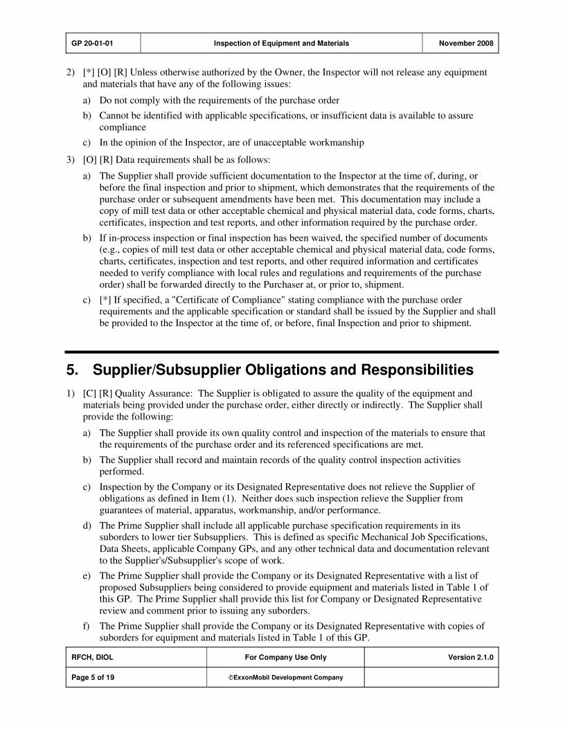
GP 20-01-01 Inspection of Equipment and Materials November 2008
RFCH, DIOL For Company Use Only Version 2.1.0
Page 5 of 19 ExxonMobil Development Company
2) [*] [O] [R] Unless otherwise authorized by the Owner, the Inspector will not release any equipment
and materials that have any of the following issues:
a) Do not comply with the requirements of the purchase order
b) Cannot be identified with applicable specifications, or insufficient data is available to assure
compliance
c) In the opinion of the Inspector, are of unacceptable workmanship
3) [O] [R] Data requirements shall be as follows:
a) The Supplier shall provide sufficient documentation to the Inspector at the time of, during, or
before the final inspection and prior to shipment, which demonstrates that the requirements of the
purchase order or subsequent amendments have been met. This documentation may include a copy of mill test data or other acceptable chemical and physical material data, code forms, charts,
certificates, inspection and test reports, and other information required by the purchase order.
b) If in-process inspection or final inspection has been waived, the specified number of documents (e.g., copies of mill test data or other acceptable chemical and physical material data, code forms,
charts, certificates, inspection and test reports, and other required information and certificates
needed to verify compliance with local rules and regulations and requirements of the purchase
order) shall be forwarded directly to the Purchaser at, or prior to, shipment.
c) [*] If specified, a "Certificate of Compliance" stating compliance with the purchase order requirements and the applicable specification or standard shall be issued by the Supplier and shall
be provided to the Inspector at the time of, or before, final Inspection and prior to shipment.
5. Supplier/Subsupplier Obligations and Responsibilities
1) [C] [R] Quality Assurance: The Supplier is obligated to assure the quality of the equipment and materials being provided under the purchase order, either directly or indirectly. The Supplier shall
provide the following:
a) The Supplier shall provide its own quality control and inspection of the materials to ensure that the requirements of the purchase order and its referenced specifications are met.
b) The Supplier shall record and maintain records of the quality control inspection activities performed.
c) Inspection by the Company or its Designated Representative does not relieve the Supplier of obligations as defined in Item (1). Neither does such inspection relieve the Supplier from
guarantees of material, apparatus, workmanship, and/or performance.
d) The Prime Supplier shall include all applicable purchase specification requirements in its suborders to lower tier Subsuppliers. This is defined as specific Mechanical Job Specifications,
Data Sheets, applicable Company GPs, and any other technical data and documentation relevant
to the Supplier's/Subsupplier's scope of work.
e) The Prime Supplier shall provide the Company or its Designated Representative with a list of
proposed Subsuppliers being considered to provide equipment and materials listed in Table 1 of this GP. The Prime Supplier shall provide this list for Company or Designated Representative
review and comment prior to issuing any suborders.
f) The Prime Supplier shall provide the Company or its Designated Representative with copies of suborders for equipment and materials listed in Table 1 of this GP.
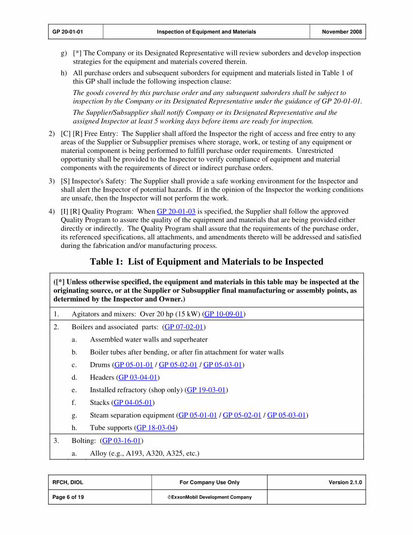
GP 20-01-01 Inspection of Equipment and Materials November 2008
RFCH, DIOL For Company Use Only Version 2.1.0
Page 6 of 19 ExxonMobil Development Company
g) [*] The Company or its Designated Representative will review suborders and develop inspection
strategies for the equipment and materials covered therein.
h) All purchase orders and subsequent suborders for equipment and materials listed in Table 1 of this GP shall include the following inspection clause:
The goods covered by this purchase order and any subsequent suborders shall be subject to
inspection by the Company or its Designated Representative under the guidance of GP 20-01-01.
The Supplier/Subsupplier shall notify Company or its Designated Representative and the
assigned Inspector at least 5 working days before items are ready for inspection.
2) [C] [R] Free Entry: The Supplier shall afford the Inspector the right of access and free entry to any areas of the Supplier or Subsupplier premises where storage, work, or testing of any equipment or
material component is being performed to fulfill purchase order requirements. Unrestricted
opportunity shall be provided to the Inspector to verify compliance of equipment and material
components with the requirements of direct or indirect purchase orders.
3) [S] Inspector's Safety: The Supplier shall provide a safe working environment for the Inspector and shall alert the Inspector of potential hazards. If in the opinion of the Inspector the working conditions
are unsafe, then the Inspector will not perform the work.
4) [I] [R] Quality Program: When GP 20-01-03 is specified, the Supplier shall follow the approved Quality Program to assure the quality of the equipment and materials that are being provided either
directly or indirectly. The Quality Program shall assure that the requirements of the purchase order,
its referenced specifications, all attachments, and amendments thereto will be addressed and satisfied
during the fabrication and/or manufacturing process.
Table 1: List of Equipment and Materials to be Inspected
([*] Unless otherwise specified, the equipment and materials in this table may be inspected at the
originating source, or at the Supplier or Subsupplier final manufacturing or assembly points, as
determined by the Inspector and Owner.)
1. Agitators and mixers: Over 20 hp (15 kW) (GP 10-09-01)
2. Boilers and associated parts: (GP 07-02-01)
a. Assembled water walls and superheater
b. Boiler tubes after bending, or after fin attachment for water walls
c. Drums (GP 05-01-01 / GP 05-02-01 / GP 05-03-01)
d. Headers (GP 03-04-01)
e. Installed refractory (shop only) (GP 19-03-01)
f. Stacks (GP 04-05-01)
g. Steam separation equipment (GP 05-01-01 / GP 05-02-01 / GP 05-03-01)
h. Tube supports (GP 18-03-04)
3. Bolting: (GP 03-16-01)
a. Alloy (e.g., A193, A320, A325, etc.)

GP 20-01-01 Inspection of Equipment and Materials November 2008
RFCH, DIOL For Company Use Only Version 2.1.0
Page 7 of 19 ExxonMobil Development Company
([*] Unless otherwise specified, the equipment and materials in this table may be inspected at the
originating source, or at the Supplier or Subsupplier final manufacturing or assembly points, as
determined by the Inspector and Owner.)
b. Material involving impact tests for services below –50 F (–45 C), including witnessing of
impact tests (GP 18-10-01)
c. Greater than 2 in. (50 mm) diameter
d. All coated bolts
4. Burners: For process equipment such as boilers, fired heaters, incinerators, sulfur plants, etc.
(GP 07-04-01)
5. Castings other than valve bodies: All ductile iron, carbon steel, and alloy castings (if not part of equipment otherwise listed in this GP) for the following: (GP 18-03-04)
a. Pressure-containing service
b. Load bearing, or critical vessel internals such as grid plates cat cracking plants
c. High temperature service [above 1000 F (538 C)]
d. Foundry for casings for compressors, pumps, turbines, and expanders developing or requiring 5000 hp (3750 kW) or more
e. Castings when "first-piece" or "pilot castings" are required
f. Castings subject to nondestructive examinations (NDE)
6. Centrifuges: Over 20 hp (15 kW) (See EMEPS Category 10 - Machinery.)
7. Circuit breakers: All circuit breakers (with associated relays and panels) rated above 600 volts
(GP 16-13-01)
8. Compressors: (GP 10-03-01 / GP 10-03-02 / GP 10-03-03 / GP 10-04-01)
a. Centrifugal, axial, and rotary screw compressors for special purpose applications
b. Packaged, integrally geared compressors
c. Reciprocating compressors for process applications
d. Other compressors, including axial, centrifugal, rotary screw, reciprocating and liquid ring compressors over 150 hp (112 kW), except laboratory units, or portable commercial units
such as for paint sprayers, sandblast machines, or gunite machines
9. Control Panels for Instruments, where functional tests or specific name brand components are
required (GP 15-11-01)
10. Cyclones and trickle valves, including installed refractory linings (shop only)
(GP 05-01-01 / GP 19-03-02)
11. Dryers (GP 03-06-01)
12. Engines: Diesel and gas over 150 hp (112 kW) (does not include drivers for construction equipment)
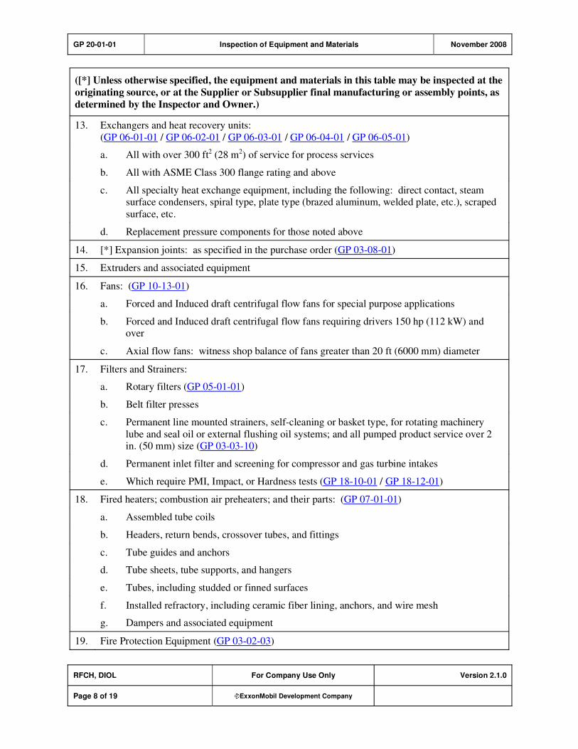
GP 20-01-01 Inspection of Equipment and Materials November 2008
RFCH, DIOL For Company Use Only Version 2.1.0
Page 8 of 19 ExxonMobil Development Company
([*] Unless otherwise specified, the equipment and materials in this table may be inspected at the
originating source, or at the Supplier or Subsupplier final manufacturing or assembly points, as
determined by the Inspector and Owner.)
13. Exchangers and heat recovery units:
(GP 06-01-01 / GP 06-02-01 / GP 06-03-01 / GP 06-04-01 / GP 06-05-01)
a. All with over 300 ft2 (28 m2) of service for process services
b. All with ASME Class 300 flange rating and above
c. All specialty heat exchange equipment, including the following: direct contact, steam surface condensers, spiral type, plate type (brazed aluminum, welded plate, etc.), scraped
surface, etc.
d. Replacement pressure components for those noted above
14. [*] Expansion joints: as specified in the purchase order (GP 03-08-01)
15. Extruders and associated equipment
16. Fans: (GP 10-13-01)
a. Forced and Induced draft centrifugal flow fans for special purpose applications
b. Forced and Induced draft centrifugal flow fans requiring drivers 150 hp (112 kW) and over
c. Axial flow fans: witness shop balance of fans greater than 20 ft (6000 mm) diameter
17. Filters and Strainers:
a. Rotary filters (GP 05-01-01)
b. Belt filter presses
c. Permanent line mounted strainers, self-cleaning or basket type, for rotating machinery
lube and seal oil or external flushing oil systems; and all pumped product service over 2 in. (50 mm) size (GP 03-03-10)
d. Permanent inlet filter and screening for compressor and gas turbine intakes
e. Which require PMI, Impact, or Hardness tests (GP 18-10-01 / GP 18-12-01)
18. Fired heaters; combustion air preheaters; and their parts: (GP 07-01-01)
a. Assembled tube coils
b. Headers, return bends, crossover tubes, and fittings
c. Tube guides and anchors
d. Tube sheets, tube supports, and hangers
e. Tubes, including studded or finned surfaces
f. Installed refractory, including ceramic fiber lining, anchors, and wire mesh
g. Dampers and associated equipment
19. Fire Protection Equipment (GP 03-02-03)
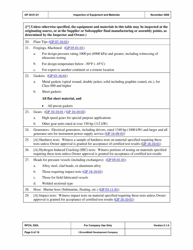
GP 20-01-01 Inspection of Equipment and Materials November 2008
RFCH, DIOL For Company Use Only Version 2.1.0
Page 9 of 19 ExxonMobil Development Company
([*] Unless otherwise specified, the equipment and materials in this table may be inspected at the
originating source, or at the Supplier or Subsupplier final manufacturing or assembly points, as
determined by the Inspector and Owner.)
20. Flare Tips (GP 07-10-01)
21. Forgings, Machined: (GP 05-01-01)
a. For design pressure rating 1000 psi (6900 kPa) and greater, including witnessing of
ultrasonic testing
b. For design temperature below –50 F (–45 C)
c. For export to another continent or a remote location
22. Gaskets: (GP 03-16-01)
a. Metal gaskets (spiral wound, double jacket, solid including graphite coated, etc.), for
Class 600 and higher
b. Sheet gaskets:
All flat sheet material, and
All precut gaskets
23. Gears: (GP 10-10-01 / GP 10-10-02)
a. High speed gears for special purpose applications
b. Other gear units rated at over 150 hp (112 kW)
24. Generators: Electrical generators, including drivers, rated 1340 hp (1000 kW) and larger and all generator sets for instrument power supply service (GP 16-09-03)
25. [A] Hardness tests: Witness a sample of hardness tests on material specified requiring these
tests unless Owner approval is granted for acceptance of certified test results (GP 18-10-01)
26. [A] Hydrogen Induced Cracking (HIC) tests: Witness portions of testing on materials specified requiring these tests unless Owner approval is granted for acceptance of certified test results
27. Heads for pressure vessels (including exchangers): (GP 05-01-01)
a. Alloy steel, clad heads, or aluminum alloy
b. Those requiring impact tests (GP 18-10-01)
c. Those for field fabricated vessels
d. Welded sectional type
28. Hose: Marine hose (Submarine, floating, etc.) (GP 03-11-01)
29. [A] Impact tests: Witness impact tests on material specified requiring these tests unless Owner
approval is granted for acceptance of certified test results (GP 18-10-01)
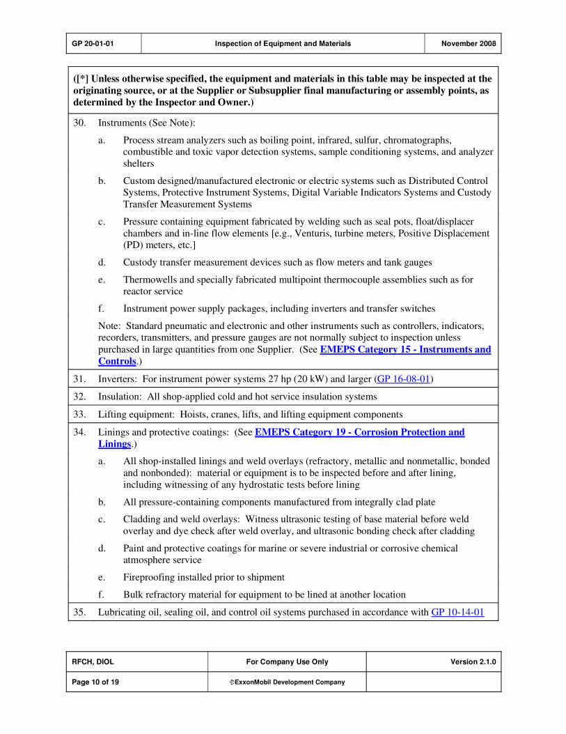
GP 20-01-01 Inspection of Equipment and Materials November 2008
RFCH, DIOL For Company Use Only Version 2.1.0
Page 10 of 19 ExxonMobil Development Company
([*] Unless otherwise specified, the equipment and materials in this table may be inspected at the
originating source, or at the Supplier or Subsupplier final manufacturing or assembly points, as
determined by the Inspector and Owner.)
30. Instruments (See Note):
a. Process stream analyzers such as boiling point, infrared, sulfur, chromatographs, combustible and toxic vapor detection systems, sample conditioning systems, and analyzer
shelters
b. Custom designed/manufactured electronic or electric systems such as Distributed Control Systems, Protective Instrument Systems, Digital Variable Indicators Systems and Custody
Transfer Measurement Systems
c. Pressure containing equipment fabricated by welding such as seal pots, float/displacer
chambers and in-line flow elements [e.g., Venturis, turbine meters, Positive Displacement (PD) meters, etc.]
d. Custody transfer measurement devices such as flow meters and tank gauges
e. Thermowells and specially fabricated multipoint thermocouple assemblies such as for reactor service
f. Instrument power supply packages, including inverters and transfer switches
Note: Standard pneumatic and electronic and other instruments such as controllers, indicators, recorders, transmitters, and pressure gauges are not normally subject to inspection unless
purchased in large quantities from one Supplier. (See EMEPS Category 15 - Instruments and
Controls.)
31. Inverters: For instrument power systems 27 hp (20 kW) and larger (GP 16-08-01)
32. Insulation: All shop-applied cold and hot service insulation systems
33. Lifting equipment: Hoists, cranes, lifts, and lifting equipment components
34. Linings and protective coatings: (See EMEPS Category 19 - Corrosion Protection and
Linings.)
a. All shop-installed linings and weld overlays (refractory, metallic and nonmetallic, bonded
and nonbonded): material or equipment is to be inspected before and after lining,
including witnessing of any hydrostatic tests before lining
b. All pressure-containing components manufactured from integrally clad plate
c. Cladding and weld overlays: Witness ultrasonic testing of base material before weld
overlay and dye check after weld overlay, and ultrasonic bonding check after cladding
d. Paint and protective coatings for marine or severe industrial or corrosive chemical atmosphere service
e. Fireproofing installed prior to shipment
f. Bulk refractory material for equipment to be lined at another location
35. Lubricating oil, sealing oil, and control oil systems purchased in accordance with GP 10-14-01
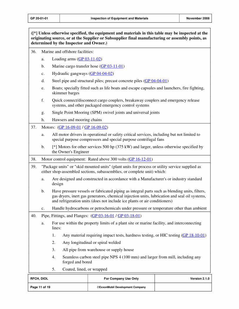
GP 20-01-01 Inspection of Equipment and Materials November 2008
RFCH, DIOL For Company Use Only Version 2.1.0
Page 11 of 19 ExxonMobil Development Company
([*] Unless otherwise specified, the equipment and materials in this table may be inspected at the
originating source, or at the Supplier or Subsupplier final manufacturing or assembly points, as
determined by the Inspector and Owner.)
36. Marine and offshore facilities:
a. Loading arms (GP 03-11-02)
b. Marine cargo transfer hose (GP 03-11-01)
c. Hydraulic gangways (GP 04-04-02)
d. Steel pipe and structural piles; precast concrete piles (GP 04-04-01)
e. Boats; specially fitted such as life boats and escape capsules and launchers, fire fighting,
skimmer barges
f. Quick connect/disconnect cargo couplers, breakaway couplers and emergency release
systems, and other packaged emergency control systems
g. Single Point Mooring (SPM) swivel joints and universal joints
h. Hawsers and mooring chains
37. Motors: (GP 16-09-01 / GP 16-09-02)
a. All motor drivers in operational or safety critical services, including but not limited to
special purpose compressors and special purpose centrifugal fans
b. [*] Motors for other services 500 hp (375 kW) and larger, unless otherwise specified by
the Owner's Engineer
38. Motor control equipment: Rated above 300 volts (GP 16-12-01)
39. "Package units" or "skid mounted units" (plant units for process or utility service supplied as
either shop-assembled sections, subassemblies, or complete unit) which:
a. Are designed and constructed in accordance with a Manufacturer's or industry standard design
b. Have pressure vessels or fabricated piping as integral parts such as blending units, filters,
gas dryers, inert gas generators, chemical injection units, lubrication and seal oil systems, and refrigeration units (does not include ice plants or air conditioners)
c. Handle hydrocarbons or petrochemicals under pressure or temperature other than ambient
40. Pipe, Fittings, and Flanges: (GP 03-16-01 / GP 03-18-01)
a. For use within the property limits of a plant site or marine facility, and interconnecting lines:
1. Any material requiring impact tests, hardness testing, or HIC testing (GP 18-10-01)
2. Any longitudinal or spiral welded
3. All pipe from warehouse or supply house
4. Seamless carbon steel pipe NPS 4 (100 mm) and larger from mill, including any
forged and bored
5. Coated, lined, or wrapped
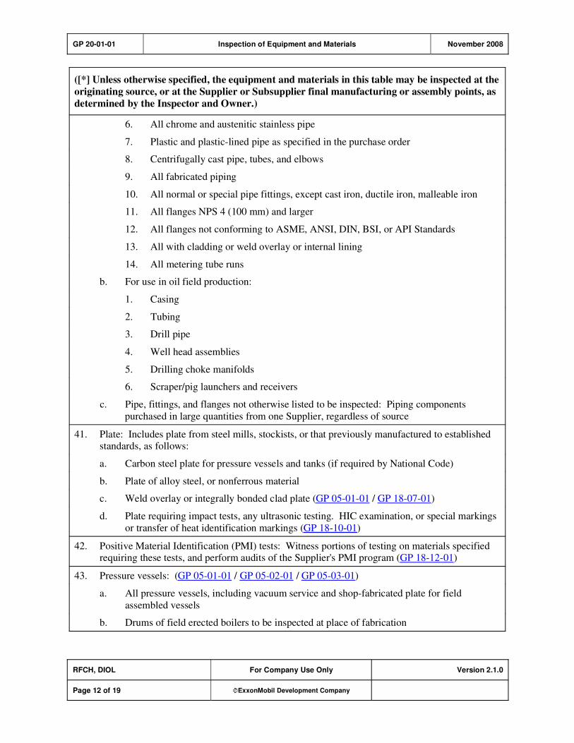
GP 20-01-01 Inspection of Equipment and Materials November 2008
RFCH, DIOL For Company Use Only Version 2.1.0
Page 12 of 19 ExxonMobil Development Company
([*] Unless otherwise specified, the equipment and materials in this table may be inspected at the
originating source, or at the Supplier or Subsupplier final manufacturing or assembly points, as
determined by the Inspector and Owner.)
6. All chrome and austenitic stainless pipe
7. Plastic and plastic-lined pipe as specified in the purchase order
8. Centrifugally cast pipe, tubes, and elbows
9. All fabricated piping
10. All normal or special pipe fittings, except cast iron, ductile iron, malleable iron
11. All flanges NPS 4 (100 mm) and larger
12. All flanges not conforming to ASME, ANSI, DIN, BSI, or API Standards
13. All with cladding or weld overlay or internal lining
14. All metering tube runs
b. For use in oil field production:
1. Casing
2. Tubing
3. Drill pipe
4. Well head assemblies
5. Drilling choke manifolds
6. Scraper/pig launchers and receivers
c. Pipe, fittings, and flanges not otherwise listed to be inspected: Piping components
purchased in large quantities from one Supplier, regardless of source
41. Plate: Includes plate from steel mills, stockists, or that previously manufactured to established standards, as follows:
a. Carbon steel plate for pressure vessels and tanks (if required by National Code)
b. Plate of alloy steel, or nonferrous material
c. Weld overlay or integrally bonded clad plate (GP 05-01-01 / GP 18-07-01)
d. Plate requiring impact tests, any ultrasonic testing. HIC examination, or special markings
or transfer of heat identification markings (GP 18-10-01)
42. Positive Material Identification (PMI) tests: Witness portions of testing on materials specified requiring these tests, and perform audits of the Supplier's PMI program (GP 18-12-01)
43. Pressure vessels: (GP 05-01-01 / GP 05-02-01 / GP 05-03-01)
a. All pressure vessels, including vacuum service and shop-fabricated plate for field
assembled vessels
b. Drums of field erected boilers to be inspected at place of fabrication
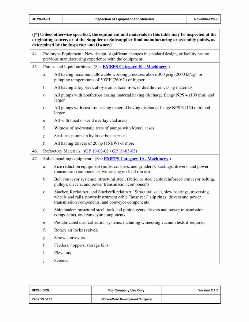
GP 20-01-01 Inspection of Equipment and Materials November 2008
RFCH, DIOL For Company Use Only Version 2.1.0
Page 13 of 19 ExxonMobil Development Company
([*] Unless otherwise specified, the equipment and materials in this table may be inspected at the
originating source, or at the Supplier or Subsupplier final manufacturing or assembly points, as
determined by the Inspector and Owner.)
44. Prototype Equipment: New design, significant changes in standard design, or facility has no
previous manufacturing experience with the equipment
45. Pumps and liquid turbines: (See EMEPS Category 10 - Machinery.)
a. All having maximum allowable working pressures above 300 psig (2000 kPag), or
pumping temperatures of 500 F (260 C) or higher
b. All having alloy steel, alloy iron, silicon iron, or ductile iron casing materials
c. All pumps with nonferrous casing material having discharge flange NPS 4 (100 mm) and larger
d. All pumps with cast iron casing material having discharge flange NPS 6 (150 mm) and
larger
e. All with lined or weld overlay clad areas
f. Witness of hydrostatic tests of pumps with Monel cases
g. Seal-less pumps in hydrocarbon service
h. All having drivers of 20 hp (15 kW) or more
46. Refractory Materials: (GP 19-03-02 / GP 19-03-03)
47. Solids handling equipment: (See EMEPS Category 10 - Machinery.)
a. Size reduction equipment (mills, crushers, and grinders): castings, drivers, and power
transmission components, witnessing no-load run test
b. Belt conveyor systems: structural steel, fabric, or steel cable reinforced conveyor belting,
pulleys, drivers, and power transmission components
c. Stacker, Reclaimer, and Stacker/Reclaimer: Structural steel, slew bearings, traversing wheels and rails, power-instrument cable "hose reel" slip rings, drivers and power
transmission components, and conveyor components
d. Ship loader: structural steel, rack and pinion gears, drivers and power transmission components, and conveyor components
e. Prefabricated dust collection systems, including witnessing vacuum tests if required
f. Rotary air locks (valves)
g. Screw conveyors
h. Feeders, hoppers, storage bins
i. Elevators
j. Screens

GP 20-01-01 Inspection of Equipment and Materials November 2008
RFCH, DIOL For Company Use Only Version 2.1.0
Page 14 of 19 ExxonMobil Development Company
([*] Unless otherwise specified, the equipment and materials in this table may be inspected at the
originating source, or at the Supplier or Subsupplier final manufacturing or assembly points, as
determined by the Inspector and Owner.)
48. Spare parts:
a. Major equipment ordered as standby spares such as compressors, and equipment components such as rotors and diaphragms and turbine blades, and other major parts for
equipment normally inspected. (See EMEPS Category 10 - Machinery.)
b. Long delivery items not normally stocked by the Manufacturer
49. Structures: (See EMEPS Category 04 - Civil.)
a. Stacks (self-supporting): Shop-fabricated steel stacks or welded courses for field erection,
breechings, and ductwork (GP 04-05-01)
b. Offshore drilling platforms
c. Pipe supports (shop fabricated only), purchased in large quantities from one Supplier
d. Structures supplied as either shop-assembled sections, subassemblies, or complete, unless
otherwise covered in this GP
50. Switchgear: All switchgear, associated relays, and control panels (GP 16-12-01)
51. Tanks or spheres (atmospheric or pressure storage): (GP 09-04-01 / GP 09-02-01)
a. Shop fabrication of shell plates
b. Complete shop-assembled tanks
c. Internal floating covers sent to job site in another hemisphere
d. Field erection
52. Vessel and tower internals: For shop and field assembly (GP 05-02-01)
53. Variable Frequency Drives: 75 hp (60 kW) and larger (GP 16-14-01 / GP 16-14-02)
54. Transformers: 500 kVA and larger, or with primary windings above 15 kV (GP 16-10-01)
55. Trucks: See Vehicles
56. Tube bundles: For exchangers over 300 ft2 (28 m
2) surface area or pressure rating requiring
ASME Class 300 flanges or over, including air-cooled heat exchangers (GP 06-01-01)
57. Tubes (exchanger, boiler, and fired heater): (See EMEPS Category 06 - Heat Exchangers and
EMEPS Category 07 - Fired Heaters and Boilers.)
a. All alloy steel
b. Nonferrous: e.g., 70Cu 30Ni, titanium, tantalum, Ni based alloys, etc.
c. Exchangers, coolers, and reboilers: integral finned, bi-metal, electrical resistance welded,
and "U" tubes (including after heat treatment)
d. Boiler tubes: after bending, or after fin attachment for water walls
e. Fired heater tubes: before and after centerwelding, stud, or fin attachment
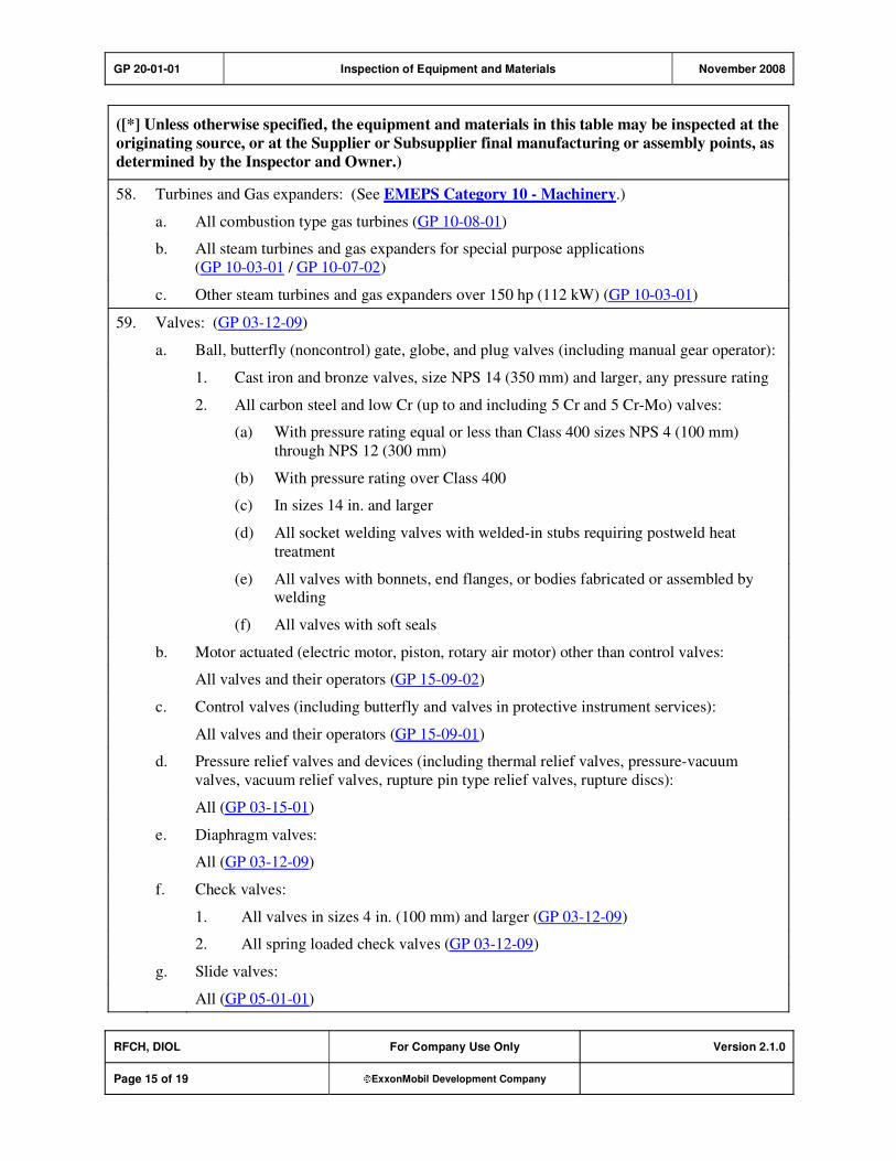
GP 20-01-01 Inspection of Equipment and Materials November 2008
RFCH, DIOL For Company Use Only Version 2.1.0
Page 15 of 19 ExxonMobil Development Company
([*] Unless otherwise specified, the equipment and materials in this table may be inspected at the
originating source, or at the Supplier or Subsupplier final manufacturing or assembly points, as
determined by the Inspector and Owner.)
58. Turbines and Gas expanders: (See EMEPS Category 10 - Machinery.)
a. All combustion type gas turbines (GP 10-08-01)
b. All steam turbines and gas expanders for special purpose applications
(GP 10-03-01 / GP 10-07-02)
c. Other steam turbines and gas expanders over 150 hp (112 kW) (GP 10-03-01)
59. Valves: (GP 03-12-09)
a. Ball, butterfly (noncontrol) gate, globe, and plug valves (including manual gear operator):
1. Cast iron and bronze valves, size NPS 14 (350 mm) and larger, any pressure rating
2. All carbon steel and low Cr (up to and including 5 Cr and 5 Cr-Mo) valves:
(a) With pressure rating equal or less than Class 400 sizes NPS 4 (100 mm)
through NPS 12 (300 mm)
(b) With pressure rating over Class 400
(c) In sizes 14 in. and larger
(d) All socket welding valves with welded-in stubs requiring postweld heat
treatment
(e) All valves with bonnets, end flanges, or bodies fabricated or assembled by welding
(f) All valves with soft seals
b. Motor actuated (electric motor, piston, rotary air motor) other than control valves:
All valves and their operators (GP 15-09-02)
c. Control valves (including butterfly and valves in protective instrument services):
All valves and their operators (GP 15-09-01)
d. Pressure relief valves and devices (including thermal relief valves, pressure-vacuum
valves, vacuum relief valves, rupture pin type relief valves, rupture discs):
All (GP 03-15-01)
e. Diaphragm valves:
All (GP 03-12-09)
f. Check valves:
1. All valves in sizes 4 in. (100 mm) and larger (GP 03-12-09)
2. All spring loaded check valves (GP 03-12-09)
g. Slide valves:
All (GP 05-01-01)
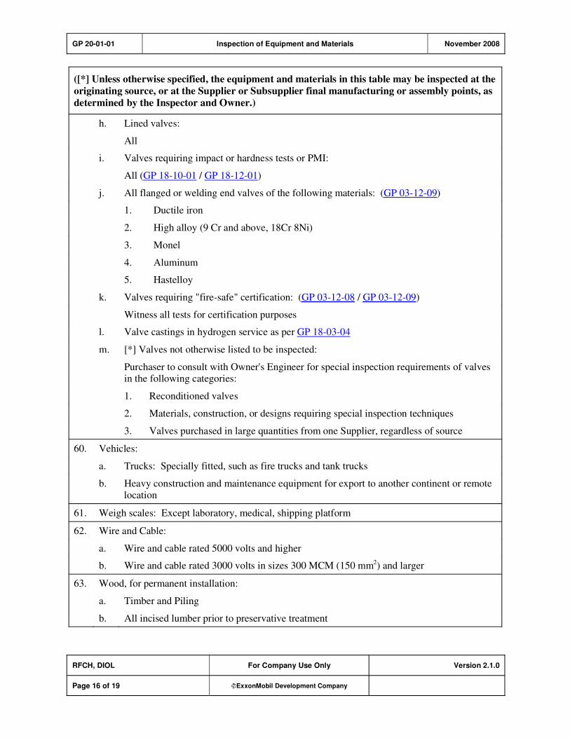
GP 20-01-01 Inspection of Equipment and Materials November 2008
RFCH, DIOL For Company Use Only Version 2.1.0
Page 16 of 19 ExxonMobil Development Company
([*] Unless otherwise specified, the equipment and materials in this table may be inspected at the
originating source, or at the Supplier or Subsupplier final manufacturing or assembly points, as
determined by the Inspector and Owner.)
h. Lined valves:
All
i. Valves requiring impact or hardness tests or PMI:
All (GP 18-10-01 / GP 18-12-01)
j. All flanged or welding end valves of the following materials: (GP 03-12-09)
1. Ductile iron
2. High alloy (9 Cr and above, 18Cr 8Ni)
3. Monel
4. Aluminum
5. Hastelloy
k. Valves requiring "fire-safe" certification: (GP 03-12-08 / GP 03-12-09)
Witness all tests for certification purposes
l. Valve castings in hydrogen service as per GP 18-03-04
m. [*] Valves not otherwise listed to be inspected:
Purchaser to consult with Owner's Engineer for special inspection requirements of valves in the following categories:
1. Reconditioned valves
2. Materials, construction, or designs requiring special inspection techniques
3. Valves purchased in large quantities from one Supplier, regardless of source
60. Vehicles:
a. Trucks: Specially fitted, such as fire trucks and tank trucks
b. Heavy construction and maintenance equipment for export to another continent or remote location
61. Weigh scales: Except laboratory, medical, shipping platform
62. Wire and Cable:
a. Wire and cable rated 5000 volts and higher
b. Wire and cable rated 3000 volts in sizes 300 MCM (150 mm2) and larger
63. Wood, for permanent installation:
a. Timber and Piling
b. All incised lumber prior to preservative treatment

GP 20-01-01 Inspection of Equipment and Materials November 2008
RFCH, DIOL For Company Use Only Version 2.1.0
Page 17 of 19 ExxonMobil Development Company
Record of Change
Version 1.0.0 Date: 07/01
Location Action Description
Initial Publish.
Version 1.0.0 Date: 07/03
Global Practice version number and format updated to comply with new
process; however, original publish date remains, and no content was
modified.
Version 1.0.0 Date: 03/05
Initial endorsement by Chemical. Due to Chemical endorsement of the
referenced GP 20-01-02, this version replaces Chemical's previous
customized Version 1.0.1.
Version 2.0.0 Date: 09/06
Section 1 Modification Added additional explanation of references.
Added/deleted references as needed per body of GP.
Section 2,
Item (4)
Addition Added reference to Projects Equipment Criticality Rating Work Process.
Section 4,
Items (1a) and
(1b)
Addition Added requirement for Purchaser to reference this GP in requisition.
Added requirement for inspection clause in purchaser's responsibilities.
Section 5,
Items (1d) to
(1h)
Addition Added clarification to Supplier obligations, roles, and responsibilities.
Added reference to technical documentation, GPs in suborders.
Added requirement for inspection clause in prime/suborders.
Table 1 Addition Added references to applicable Global Practices.
General Modification Added purpose codes throughout GP.
All Global
Practices
Modifications To standardize the format of the Global Practices and to meet other requirements, the following changes have been implemented:
"For ExxonMobil Use Only" has been replaced with "For Company Use
Only."
A copyright waiver has been added in the first page Footer.
The definition of asterisks in the Scope has been deleted. The asterisk is
now defined in the Purpose Code attachment and is used within brackets
as other Purpose Codes.
Multiple paragraphs within a Section have been numbered.
The standard text for Required References has been modified.
The standard text for Additional Requirements has been modified.

GP 20-01-01 Inspection of Equipment and Materials November 2008
RFCH, DIOL For Company Use Only Version 2.1.0
Page 18 of 19 ExxonMobil Development Company
The [S] Purpose Code has been modified.
The following Purpose Codes have been added:
[*] for additional information or decision required of Owner's
Engineer.
[A] for approval requirements before beginning work or finalizing
design.
Version 2.1.0 Date: 11/08
Table 1 Modification Deleted inactive reference GP 10-13-02.

GP 20-01-01 Inspection of Equipment and Materials November 2008
RFCH, DIOL For Company Use Only Version 2.1.0
Page 19 of 19 ExxonMobil Development Company
Attachment: Purpose Code Definitions
Code Description
* Assigned to paragraphs that require the Owner's Engineer to provide additional information or
make a decision.
A Assigned to paragraphs that require approval from the Owner's Engineer before the work may
proceed or the design is finalized.
C Assigned to paragraphs whose primary purpose is reduced costs. Reduced cost in this context
refers to initial investment cost and does not include life cycle cost considerations. Life cycle
cost considerations are captured under reliability, maintainability, or operability purpose codes.
E Assigned to paragraphs whose primary purpose is driven by environmental considerations. Environmental considerations typically include specifications intended to protect against
emissions/leakage to the air, water, and/or soil. Deviations from the specifications contained
in such paragraphs require formal review and approval according to local environmental policy.
I Assigned to paragraphs that provide only clarifying information, such as Scope statements,
definitions of terms, etc.
M Assigned to paragraphs whose primary purpose is to provide for maintainability of equipment or systems. Maintainability provisions are those that facilitate the performance of maintenance
on equipment/systems either during downtimes or during onstream operations.
O Assigned to paragraphs whose primary purpose is to assure operability of equipment or
systems. Operability is the ability of the equipment/system to perform satisfactorily even though conditions are off-design, such as during start-ups, process swings, subcomponent
malfunction, etc.
R Assigned to paragraphs whose primary purpose is to improve or assure the reliability of
equipment or systems. Reliability is a measure of the ability of equipment/systems to operate without malfunction or failure between planned maintenance interventions.
S Assigned to paragraphs containing specifications/guidance where the primary purpose is the
avoidance of incidents impacting personnel safety, operational safety, and the public in general and/or involving responses to emergency situations. Any deviation from the specifications
contained in such designated paragraphs requires formal review and approval according to
local safety policy.
Personnel Safety: Refers to incident-related personnel injuries or illness, e.g., burns, cuts, abrasions, inhalation of or exposure to dangerous substances, etc., that
could result in medical treatment, restricted work, lost-time incidents, or
fatalities.
Operational
Safety:
Refers to the prevention and control of process releases, fires, and/or
explosions that could result in damage to equipment, process disruption,
or personnel injury or illness.

GP 20-01-02 Administrative Procedures for Obtaining Inspection January 2007
Refining/Chemicals, Downstream Imperial Oil
For Company Use Only Version 2.0.0
Page 1 of 14 ExxonMobil Development Company
Copyright Waiver ExxonMobil Development Company and ExxonMobil Pipeline Company hereby license the use of ExxonMobil Engineering Practices System (EMEPS) Global Practices (GPs) for use by any ExxonMobil division, subsidiary, or more-than-50%-owned affiliate. The GPs may be downloaded and modified as necessary for project and affiliate use. Written permission from ExxonMobil Development Company or ExxonMobil Pipeline Company is not required. However, any modified GPs must be renumbered to a project-specific or affiliate-specific number to distinguish them from the GPs on the EMEPS web site. ExxonMobil operated joint ventures may utilize GPs to create project-specific or location-specific specifications. It is the responsibility of individual affiliate or joint venture to ensure that the use of GPs and their derivatives is limited to joint venture related business and not disclosed or used outside the JV without appropriate EM management approval.
Administrative Procedures for Obtaining Inspection
GP 20-01-02
Scope
1) [I] This Global Practice (GP) covers administrative procedures applicable when material or equipment is to be inspected by the Company or an appointed Owner's Representative.
2) [*] [R] This Practice shall be applied to any direct or indirect Purchase Orders or suborders issued on
behalf of or by the Company when inspection is required by GP 20-01-01, or when specified by the Purchaser.
GP 20-01-02 Administrative Procedures for Obtaining Inspection January 2007
RFCH, DIOL For Company Use Only Version 2.0.0
Page 2 of 14 ExxonMobil Development Company
Table of Contents
1. Required References ............................................................................................ 3
1.1. Global Practices–ExxonMobil Engineering Practices ................................... 3
1.2. ExxonMobil Research and Engineering (EMRE) Inspection Request .......... 3
2. Definitions.............................................................................................................. 4
3. Procedures ............................................................................................................ 5
3.1. Inspection Notification .................................................................................. 8
3.2. Waiver of Inspection ..................................................................................... 8
3.3. Inspection and Data Requirements .............................................................. 8
3.4. Surveillance Reports .................................................................................... 9
4. Supplier/Subsupplier Obligations and Responsibilities.................................... 9
5. Alternative Inspection by Purchaser ................................................................. 10
Record of Change ....................................................................................................... 12
Attachment: Purpose Code Definitions.................................................................... 14

GP 20-01-02 Administrative Procedures for Obtaining Inspection January 2007
RFCH, DIOL For Company Use Only Version 2.0.0
Page 3 of 14 ExxonMobil Development Company
1. Required References
This section lists the Practices, codes, standards, specifications, and publications that shall be used with this document. Unless otherwise specified herein, use the latest edition.
1.1. Global Practices–ExxonMobil Engineering Practices
GP 20-01-01 Inspection of Equipment and Materials
GP 20-01-03 Quality Programs
1.2. ExxonMobil Research and Engineering (EMRE) Inspection Request
GP200102 IR FORM Inspection Request Form
To engage EMRE Inspection, complete GP200102 IR FORM and submit to the respective AEO
Inspection Coordinator listed in Table 1 of this GP.
1) [I] The EMRE Inspection Request Form includes two drop-down "selection" boxes in Section 4 to assist in defining Equipment Criticality. The first drop-down selection is for defining the Criticality
Assessment of the Equipment/System. The second is for defining the basis for the Criticality Assessment., using either Table 1 (predefined list) or Table 2, Criticality Assessment Worksheet. If
Table 2 is used, the requester is to include a copy with the request.
Note that the EMRE Equipment Criticality Assessment Work Process is based on the corporate risk
matrix approach, with SHE and Financial consequences assessed separately.
2) The Inspection Request shall include all purchase specification requirements, e.g., copy of Purchase
Order, mechanical job specification, and reference to all applicable ExxonMobil Global Practices
(GPs), ExxonMobil AML, General ExxonMobil Piping Material Specifications (GEMS), site-specific General Information and Instructions (GIIs), etc., applicable to the Vendor's scope of supply.
3) EMRE Inspection will review the data submitted and develop an Inspection Plan commensurate with
the purchase specification requirements and the Equipment/System Criticality Rating.
4) EMRE Inspection will submit an Inspection Plan to the requester for review and comment before commencing inspection activities.
5) [R] Equipment/Systems with Criticality Rating I: EMRE Inspection requires owner endorsement
of the proposed inspection plan before the work can proceed.

GP 20-01-02 Administrative Procedures for Obtaining Inspection January 2007
RFCH, DIOL For Company Use Only Version 2.0.0
Page 4 of 14 ExxonMobil Development Company
2. Definitions
Term [I] Description
Company ExxonMobil or ExxonMobil Affiliates.
Direct Orders Purchase Orders issued to a Supplier on behalf of or by the Company, or
a Company Affiliate, for materials or equipment. These are also known as Main Orders or Prime Orders.
Indirect Orders Purchase Orders issued by a Supplier (who is a recipient of a Direct
Order) for mill or foundry materials or component parts or
subassemblies for fabrication or assembly. These are also known as suborders, shop orders, internal work orders, etc.
Indirect orders also include subcontracts issued to a Supplier on behalf
of, or by the Company or a Company Affiliate for the design and/or supply of materials, equipment, large special purpose package units, and
possible execution at the job site.
Inspector As used in this Practice, refers to the Company Inspector, or the
appointed Owner's or Purchaser's Representative.
Owner Company or Company Affiliate organization that will receive the
equipment or materials.
Purchase Order
(Contract)
As used in this Practice, includes the Purchase Order (or Contract)
document, its referenced Specifications and Practices, Attachments, Codes, Standards, other referenced documents, and all agreed on
amendments thereto.
Purchase Order
Package
Includes a direct or indirect Purchase Order with the following
attachments:
a. Applicable Practices or equivalent technical specifications and narrative and Technical Data Sheet specifications, and applicable
drawings.
b. Copies, or complete identification of applicable Codes, Standards, Specifications, and Publications.
c. Applicable transportation and documentation instructions.
Purchaser May be the Company, a Company Affiliate organization, or a Company designated Representative responsible for procuring equipment,
components, materials, systems, or services.
Supplier As used in this GP, refers to the Manufacturer, Vendor, Prime Supplier,
Subsupplier, Contractor or Subcontractor, and/or the recipient of the Purchase Order/Suborder.
GP 20-01-02 Administrative Procedures for Obtaining Inspection January 2007
RFCH, DIOL For Company Use Only Version 2.0.0
Page 5 of 14 ExxonMobil Development Company
3. Procedures
1) [*] [R] Equipment and materials listed in Table 1 of GP 20-01-01 and/or as specified by the Purchase Order or subsequent Suborders are subject to inspection by the Company or its designated
Representative.
2) [I] The EMRE Inspection Office or its designated Representative shall furnish the Supplier and
Subsupplier with a notification of intent to inspect material and equipment at the Supplier's/Subsupplier's works.
3) EMRE or its designated Inspection Representative will provide the Supplier/Subsupplier with written
notification of their involvement and confirm contact information for the nominated Inspector.
4) [I] Direct and indirect Purchase Orders for items to be inspected shall include the inspection clause
shown below.
The goods covered by this Purchase Order and any subsequent Suborders shall be subject to
inspection by the Company or its designated Representative under the guidance of GP 20-01-01.
The Supplier/Subsupplier shall notify the Company or its designated Representative and the assigned Inspector at least 5 working days before items are ready for inspection.
5) [I] Each Purchase Order and any correspondence pertaining thereto shall include the following:
a) Contractor Project Identification Number or the Purchase Order number of Company Affiliate, or
Client, as applicable
b) Any Purchase Order numbers assigned by Contractor, Manufacturer, or Vendor
c) Project or Affiliate designation
6) [*] [I] Copies of Purchase Orders/Suborders and all related technical data, documentation, and correspondence shall be sent in electronic format to the nearest EMRE Inspection office listed in
Table 1 of this GP, unless Purchaser advises otherwise.
If the location of a Fabricator/Manufacturer is unknown, the Purchaser may contact the nearest EMRE Inspection office listed in Table 1 of this GP for advice or instruction.
7) [*] [I] Copies of any follow-up correspondence pertaining to Purchase Orders/Suborders shall be sent in electronic format to the appropriate EMRE Inspection Office listed in Table 1 of this GP or to the
Company's designated Representative.
8) Correspondence pertaining to drawings, manufacturing data, welding, or test procedures shall include
the appropriate document identification number, revision number, and date. This shall assure that the Inspector will have reference to the correct and most recent version of fabrication/manufacturing
documents during execution of the inspection activities.

GP 20-01-02 Administrative Procedures for Obtaining Inspection January 2007
RFCH, DIOL For Company Use Only Version 2.0.0
Page 6 of 14 ExxonMobil Development Company
Table 1: Administrative Procedures for Obtaining Vendor Surveillance for
Procured Equipment/Materials
Location of Manufacture Regional Inspection Offices, Address, Telephone, Facsimile, E-Mail, or
Internet web site at http://emre.na.xom.com/home/engproj/aeos.htm
A. Jay Weick, Regional Inspection Supervisor
ExxonMobil Research & Engineering Company - Americas Regional Engineering Office - Quality Assurance Headquarters
PO Box 2954, 2800 Decker Drive Baytown, Texas 77522-2954
Telephone: (281) 834-3542
Facsimile: (281) 834-3571
E-Mail: A Jay Weick/ Baytown/ExxonMobil@xom
Internet: [email protected]
Send Inspection Request and purchase documentation to:
Jenny M. Prasek - Inspection Coordinator, Americas AEO Baytown
E-Mail: [email protected]
Tel: (281) 834-3547
Mary H. Walker - Inspection Coordinator, BRRF - BRCP Only
Tel: (225) 977-5751
E-Mail: [email protected]
North America
South America
Central America
Caribbean Countries
For additional information and to obtain an Inspection Request Form visit
the AAEO Quality Assurance/Source Inspection web site.
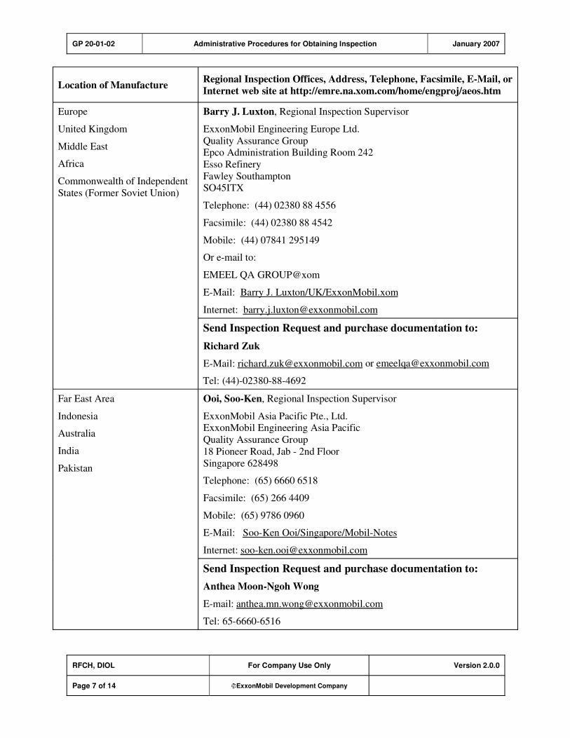
GP 20-01-02 Administrative Procedures for Obtaining Inspection January 2007
RFCH, DIOL For Company Use Only Version 2.0.0
Page 7 of 14 ExxonMobil Development Company
Location of Manufacture Regional Inspection Offices, Address, Telephone, Facsimile, E-Mail, or
Internet web site at http://emre.na.xom.com/home/engproj/aeos.htm
Barry J. Luxton, Regional Inspection Supervisor
ExxonMobil Engineering Europe Ltd.
Quality Assurance Group Epco Administration Building Room 242
Esso Refinery
Fawley Southampton SO45ITX
Telephone: (44) 02380 88 4556
Facsimile: (44) 02380 88 4542
Mobile: (44) 07841 295149
Or e-mail to:
EMEEL QA GROUP@xom
E-Mail: Barry J. Luxton/UK/ExxonMobil.xom
Internet: [email protected]
Europe
United Kingdom
Middle East
Africa
Commonwealth of Independent
States (Former Soviet Union)
Send Inspection Request and purchase documentation to:
Richard Zuk
E-Mail: [email protected] or [email protected]
Tel: (44)-02380-88-4692
Ooi, Soo-Ken, Regional Inspection Supervisor
ExxonMobil Asia Pacific Pte., Ltd. ExxonMobil Engineering Asia Pacific
Quality Assurance Group
18 Pioneer Road, Jab - 2nd Floor
Singapore 628498
Telephone: (65) 6660 6518
Facsimile: (65) 266 4409
Mobile: (65) 9786 0960
E-Mail: Soo-Ken Ooi/Singapore/Mobil-Notes
Internet: [email protected]
Far East Area
Indonesia
Australia
India
Pakistan
Send Inspection Request and purchase documentation to:
Anthea Moon-Ngoh Wong
E-mail: [email protected]
Tel: 65-6660-6516

GP 20-01-02 Administrative Procedures for Obtaining Inspection January 2007
RFCH, DIOL For Company Use Only Version 2.0.0
Page 8 of 14 ExxonMobil Development Company
Location of Manufacture Regional Inspection Offices, Address, Telephone, Facsimile, E-Mail, or
Internet web site at http://emre.na.xom.com/home/engproj/aeos.htm
General Inspection Business Steven G. Fess, Section Head - Materials and Inspection
ExxonMobil Research & Engineering Company
Americas Regional Engineering Office - Quality Assurance Headquarters Materials, Inspection And Support Group
PO Box 2954, 2800 Decker Drive
Baytown, Texas 77522-2954
Telephone: (281) 834-7548
Facsimile: (281) 834-3571
E-Mail: Steven.g.fess/Baytown/ExxonMobil@xom
Internet: [email protected]
3.1. Inspection Notification
1) [*] [C] [R] Advance notice. Supplier/Subsupplier shall notify the appropriate EMRE Inspection
Office and assigned Inspector at least 5 working days before items are ready for inspection. In all cases, notification shall be given prior to painting or preparation for shipment.
If progressive inspection is to be performed during shop fabrication (e.g., heat exchangers, vessels,
tanks, boilers, compressors), Inspector shall be notified of the date that shop fabrication/assembly begins.
2) [I] Advance inspection notice should be communicated by e-mail, (letter, telephone, or facsimile may
also be used), and shall include the following:
a) Contractor Project Identification Number or the Purchase Order number of the Company Affiliate
b) Purchase Order numbers assigned by the Company's designated Representative, Supplier,
Manufacturer, or Vendor
c) Company project or Affiliate designation
d) Indication of which portion of the order is ready for inspection
e) EMRE assigned Inspection File Number
3.2. Waiver of Inspection
1) [A] [C] [I] Inspector may waive the inspection of any item, as approved by Owner's Engineer. In this
case, written notification of the waiver shall be furnished to both Purchaser and Supplier.
2) Waiver of source inspection shall not prejudice the right to reject equipment or materials upon delivery to final destination.
3.3. Inspection and Data Requirements
1) [O] [R] At the time of final inspection and prior to shipment, Supplier shall furnish the Inspector with
sufficient documentation to demonstrate that the requirements of the Purchase Order or subsequent
amendments have been satisfied. Such documentation may include the following:

GP 20-01-02 Administrative Procedures for Obtaining Inspection January 2007
RFCH, DIOL For Company Use Only Version 2.0.0
Page 9 of 14 ExxonMobil Development Company
a) A copy of certified mill test reports or other acceptable chemical and physical material data,
b) Code forms
c) Charts
d) Certificates
e) Inspection and test reports
f) Any other documentation required by the Purchase Order.
2) Inspector shall not release equipment or materials until he/she has received and endorsed the Supplier's data and documentation and is satisfied that it meets the purchase specification
requirements.
3) [O] [R] Certified mill test reports/certificates or certified tests of physical and chemical properties
may be considered adequate documentation. Further witnessing of tests may not be required unless justified by the experience of EMRE Inspection Office, or as specified below.
Impact tests shall be witnessed by the Inspector. Witnessing shall include the identification of
samples prior to removal from the parent metal. The Inspector shall selectively witness hardness, Hydrogen Induced Cracking (HIC), and Positive Material Identification (PMI) testing. Additionally,
the Inspector shall witness all pressure vessel hydrostatic testing.
4) [I] The sections above refer to the documentation and testing requirements that must be either endorsed or witnessed by Inspector, and is separate from the data dossier that Supplier shall provide
to Purchaser at the conclusion of fabrication.
3.4. Surveillance Reports
1) [I] Inspector shall issue a Surveillance Report indicating that Supplier is released to ship materials and
equipment pending Owner's instructions immediately after receiving required data and after verification of satisfactory compliance with the purchase specification requirements.
2) [O] [R] Inspector shall be responsible for reporting details of nonconforming equipment or material in
the appropriate section of his/her Surveillance Report after inspection at Supplier's/Subsupplier's
works. Equipment and materials shipped to the job site without inspection or release shall not be accepted.
4. Supplier/Subsupplier Obligations and Responsibilities
1) [C] [R] Quality Assurance: The Supplier is obligated to assure the quality of the equipment and
materials being provided under the purchase order, either directly or indirectly. The Supplier shall
provide the following:
a) The Supplier shall provide its own quality control and inspection of the materials to ensure that
the requirements of the purchase order and its referenced specifications are met.
b) The Supplier shall record and maintain records of the quality control inspection activities performed.
c) Inspection by the Company or its Designated Representative does not relieve the Supplier of obligations as defined in Item (1). Neither does such inspection relieve the Supplier from
guarantees of material, apparatus, workmanship, and/or performance.
GP 20-01-02 Administrative Procedures for Obtaining Inspection January 2007
RFCH, DIOL For Company Use Only Version 2.0.0
Page 10 of 14 ExxonMobil Development Company
d) The Prime Supplier shall include all applicable purchase specification requirements in its
suborders to lower tier Subsuppliers. This is defined as specific Mechanical Job Specifications,
Data Sheets, applicable Company GPs, and any other technical data and documentation relevant to the Supplier's/Subsupplier's scope of work.
e) The Prime Supplier shall provide the Company or its Designated Representative with a list of proposed Subsuppliers being considered to provide equipment and materials listed in Table 1 of
GP 20-01-01. The Prime Supplier shall provide this list for Company or Designated
Representative review and comment prior to issuing any suborders.
f) The Prime Supplier shall provide the Company or its Designated Representative with copies of
suborders for equipment and materials listed in Table 1 of GP 20-01-01.
g) [*] The Company or its Designated Representative will review suborders and develop inspection strategies for the equipment and materials covered therein.
h) All purchase orders and subsequent suborders for equipment and materials listed in Table 1 of GP20-01-01 shall include the following inspection clause:
The goods covered by this Purchase Order and any subsequent Suborders shall be subject to
inspection by the Company or its designated Representative under the guidance of GP 20-01-01.
The Supplier/Subsupplier shall notify the Company or its designated Representative and the assigned
Inspector at least 5 working days before items are ready for inspection.
2) [C] [R] Free Entry: The Supplier shall afford the Inspector the right of access and free entry to any
areas of the Supplier or Subsupplier premises where storage, work, or testing of any equipment or material component is being performed to fulfill purchase order requirements. Unrestricted
opportunity shall be provided to the Inspector to verify compliance of equipment and material
components with the requirements of direct or indirect purchase orders.
3) [S] Inspector's Safety: The Supplier shall provide a safe working environment for the Inspector and shall alert the Inspector of potential hazards. If in the opinion of the Inspector the working conditions
are unsafe, then the Inspector will not perform the work.
4) [I] [R] Quality Program: When GP 20-01-03 is specified, the Supplier shall follow the approved
Quality Program to assure the quality of the equipment and materials that are being provided either directly or indirectly. The Quality Program shall assure that the requirements of the purchase order,
its referenced specifications, all attachments, and amendments thereto will be addressed and satisfied
during the fabrication and/or manufacturing process.
5. Alternative Inspection by Purchaser
1) [*] [I] At Purchasers' discretion, inspection may be arranged through a qualified third party of their choice. All of the administrative procedures, obligations, and requirements detailed in this GP shall
apply whether or not the EMRE Inspection Office is involved with the inspection.
2) [I] Should Purchaser decide to undertake responsibility for inspection, the following points should be
considered:
a) Purchaser should complete a criticality assessment of the equipment/commodity to be inspected.

GP 20-01-02 Administrative Procedures for Obtaining Inspection January 2007
RFCH, DIOL For Company Use Only Version 2.0.0
Page 11 of 14 ExxonMobil Development Company
b) Purchaser should develop detailed inspection instructions based on the criticality of the
equipment/commodity being fabricated.
c) Purchaser may consult with the nearest EMRE Regional Inspection Office for additional information and assistance.

GP 20-01-02 Administrative Procedures for Obtaining Inspection January 2007
RFCH, DIOL For Company Use Only Version 2.0.0
Page 12 of 14 ExxonMobil Development Company
Record of Change
Version 1.0.0 Date: 01/02
Location Action Description
Initial Publish.
Version 1.0.0 Date: 07/03
Global Practice version number and format updated to comply with new
process; however, original publish date remains, and no content was
modified.
Version 1.1.0 Date: 03/05
Table 1 Modification Update reflecting changes in organization.
Section 3.4,
Items (1) and
(3)
Modification Minor change to Data Requirements.
Section 3.5 Modification Change to Section name and to reporting requirements.
Section 5 Addition New section addressing alternative inspection by Purchaser.
Initial endorsement by Chemical.
Version 2.0.0 Date: 01/07
Section 1. Modification Editorial change
Section 1.1 Addition GP 20-01-03 was added as a reference.
Section 1.2 Modification Added EMRE Inspection Request Form, GP200102IR Form, as a
reference.
Section 1.2 Modification Added instructions for engaging EMRE Inspection.
Section 2 Modification Added definition of "Company."
Section 3. Modification Editorial changes.
Section 3, Item
(4)
Modification Purchase Order Inspection clause wording was changed.
Section 3.1 Modification Editorial change/clarification.
Section 3.2 Modification Added instructions for submitting inspection request.
Section 3.3 Modification Title change.
Table 1 Modification Update reflecting changes in organization.

GP 20-01-02 Administrative Procedures for Obtaining Inspection January 2007
RFCH, DIOL For Company Use Only Version 2.0.0
Page 13 of 14 ExxonMobil Development Company
Section 4 Modification Title change and editorial change. Supplier/Subsupplier Obligations and
Responsibilities changed to be consistent with GP 20-01-01
requirements.
Section 4, Item
(2)
Modification Editorial change.
Section 4, Item
(4)
Modification Added reference to GP 20-01-03 Quality Programs.
All Global
Practices
Modifications To standardize the format of the Global Practices and to meet other
requirements, the following changes have been implemented:
"For ExxonMobil Use Only" has been replaced with "For Company Use
Only."
A copyright waiver has been added in the first page Footer.
The definition of asterisks in the Scope has been deleted. The asterisk is
now defined in the Purpose Code attachment and is used within brackets
as other Purpose Codes.
Multiple paragraphs within a Section have been numbered.
The standard text for Required References has been modified.
The standard text for Additional Requirements has been modified.
The [S] Purpose Code has been modified.
The following Purpose Codes have been added:
[*] for additional information or decision required of Owner's Engineer.
[A] for approval requirements before beginning work or finalizing
design.

GP 20-01-02 Administrative Procedures for Obtaining Inspection January 2007
RFCH, DIOL For Company Use Only Version 2.0.0
Page 14 of 14 ExxonMobil Development Company
Attachment: Purpose Code Definitions
Code Description
* Assigned to paragraphs that require the Owner's Engineer to provide additional information or
make a decision.
A Assigned to paragraphs that require approval from the Owner's Engineer before the work may
proceed or the design is finalized.
C Assigned to paragraphs whose primary purpose is reduced costs. Reduced cost in this context
refers to initial investment cost and does not include life cycle cost considerations. Life cycle
cost considerations are captured under reliability, maintainability, or operability purpose codes.
E Assigned to paragraphs whose primary purpose is driven by environmental considerations. Environmental considerations typically include specifications intended to protect against
emissions/leakage to the air, water, and/or soil. Deviations from the specifications contained
in such paragraphs require formal review and approval according to local environmental policy.
I Assigned to paragraphs that provide only clarifying information, such as Scope statements,
definitions of terms, etc.
M Assigned to paragraphs whose primary purpose is to provide for maintainability of equipment or systems. Maintainability provisions are those that facilitate the performance of maintenance
on equipment/systems either during downtimes or during onstream operations.
O Assigned to paragraphs whose primary purpose is to assure operability of equipment or
systems. Operability is the ability of the equipment/system to perform satisfactorily even though conditions are off-design, such as during start-ups, process swings, subcomponent
malfunction, etc.
R Assigned to paragraphs whose primary purpose is to improve or assure the reliability of
equipment or systems. Reliability is a measure of the ability of equipment/systems to operate without malfunction or failure between planned maintenance interventions.
S Assigned to paragraphs containing specifications/guidance where the primary purpose is the
avoidance of incidents impacting personnel safety, operational safety, and the public in general and/or involving responses to emergency situations. Any deviation from the specifications
contained in such designated paragraphs requires formal review and approval according to
local safety policy.
Personnel Safety: Refers to incident-related personnel injuries or illness, e.g., burns, cuts, abrasions, inhalation of or exposure to dangerous substances, etc., that
could result in medical treatment, restricted work, lost-time incidents, or
fatalities.
Operational
Safety:
Refers to the prevention and control of process releases, fires, and/or
explosions that could result in damage to equipment, process disruption,
or personnel injury or illness.
GP 20-01-03 Quality Programs July 2001
Refining/Chemicals For ExxonMobil Use Only Version 1.0.0
Page 1 of 8 ExxonMobil Development Company
Quality Programs
GP 20-01-03
Scope
1) [I] This Global Practice (GP) covers the minimum standards for Quality Programs for specific
equipment, components, materials, systems, or services to be provided or furnished to ExxonMobil, or ExxonMobil affiliates. The purpose of the Quality Program is to identify the procedures and
controls to be implemented by the affected organization to ensure the equipment, components,
materials, systems, or services within the scope of supply meet the specified requirements.
2) [I] When specified, this GP shall be applied to any direct or indirect purchase orders, sub orders, or services agreement for or by ExxonMobil or ExxonMobil affiliates.
3) [I] An asterisk (*) indicates that a decision by Purchaser is required or that additional information is
provided by Purchaser.
GP 20-01-03 Quality Programs July 2001
RFCH For ExxonMobil Use Only Version 1.0.0
Page 2 of 8 ExxonMobil Development Company
Table of Contents
1. Required References ............................................................................................ 3
1.1. ASQ–American Society for Quality............................................................... 3
2. Definitions.............................................................................................................. 3
3. Procedures ............................................................................................................ 3
4. Quality Audits........................................................................................................ 3
Record of Change ......................................................................................................... 3
Attachment: Purpose Codes Definitions.................................................................... 3

GP 20-01-03 Quality Programs July 2001
RFCH For ExxonMobil Use Only Version 1.0.0
Page 3 of 8 ExxonMobil Development Company
1. Required References
This Section lists Practices and Standards that are generically referenced and assumed to be a part of this document. Unless otherwise specified herein, use the latest edition.
1.1. ASQ–American Society for Quality
ASQ A8402 Quality Management and Quality Assurance - Vocabulary
ASQ C1 Specification of General Requirements for a Quality Program
ASQ Q9000-1 Quality Management and Quality Assurance Standards - Guidelines for
Selection and Use
ASQ Q9000-2 Quality Management and Quality Assurance Standards - Part 2: Guidelines for Implementing ANSI/ISO/ASQC Q9001, ANSI/ISO/ASQC
Q9002 and ANSI/ISO/ASQC Q9003
ASQ Q9001 Quality Management Systems - Requirements
2. Definitions
Term Definition
Affected Organization Affected Organization is the individual or organization upon whom this
GP is imposed.
Auditor Auditor is the individual who carries out the audit.
Direct Orders Direct Orders are Purchase orders issued to a Supplier on behalf of, or by ExxonMobil or an ExxonMobil Affiliate, for materials or equipment.
(These are also known as main orders or prime orders.)
External Audits External Audits are quality audits performed by Purchaser.
Indirect Orders Indirect Orders are Purchase orders issued by a Supplier (who is recipient of a direct order) for mill or foundry materials or component parts or
subassemblies for fabrication or assembly. (These are also known as sub
orders, shop orders, internal work orders, etc.)
Purchaser Purchaser may be ExxonMobil, an ExxonMobil affiliate organization, or ExxonMobil designated representative responsible for procuring
equipment, components, materials, systems, or services.
Quality Assurance Quality Assurance includes planned and systematic actions necessary to
provide adequate confidence that a product or service or a project shall satisfy given quality requirements.
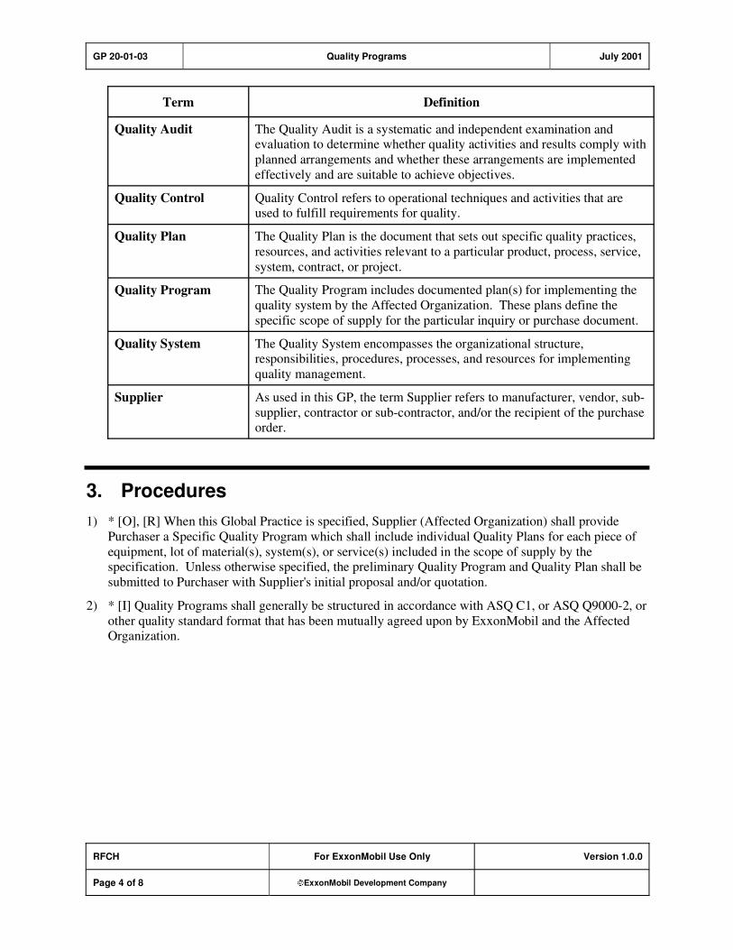
GP 20-01-03 Quality Programs July 2001
RFCH For ExxonMobil Use Only Version 1.0.0
Page 4 of 8 ExxonMobil Development Company
Term Definition
Quality Audit The Quality Audit is a systematic and independent examination and evaluation to determine whether quality activities and results comply with
planned arrangements and whether these arrangements are implemented
effectively and are suitable to achieve objectives.
Quality Control Quality Control refers to operational techniques and activities that are used to fulfill requirements for quality.
Quality Plan The Quality Plan is the document that sets out specific quality practices,
resources, and activities relevant to a particular product, process, service,
system, contract, or project.
Quality Program The Quality Program includes documented plan(s) for implementing the
quality system by the Affected Organization. These plans define the
specific scope of supply for the particular inquiry or purchase document.
Quality System The Quality System encompasses the organizational structure, responsibilities, procedures, processes, and resources for implementing
quality management.
Supplier As used in this GP, the term Supplier refers to manufacturer, vendor, sub-
supplier, contractor or sub-contractor, and/or the recipient of the purchase order.
3. Procedures
1) * [O], [R] When this Global Practice is specified, Supplier (Affected Organization) shall provide
Purchaser a Specific Quality Program which shall include individual Quality Plans for each piece of
equipment, lot of material(s), system(s), or service(s) included in the scope of supply by the specification. Unless otherwise specified, the preliminary Quality Program and Quality Plan shall be
submitted to Purchaser with Supplier's initial proposal and/or quotation.
2) * [I] Quality Programs shall generally be structured in accordance with ASQ C1, or ASQ Q9000-2, or
other quality standard format that has been mutually agreed upon by ExxonMobil and the Affected Organization.
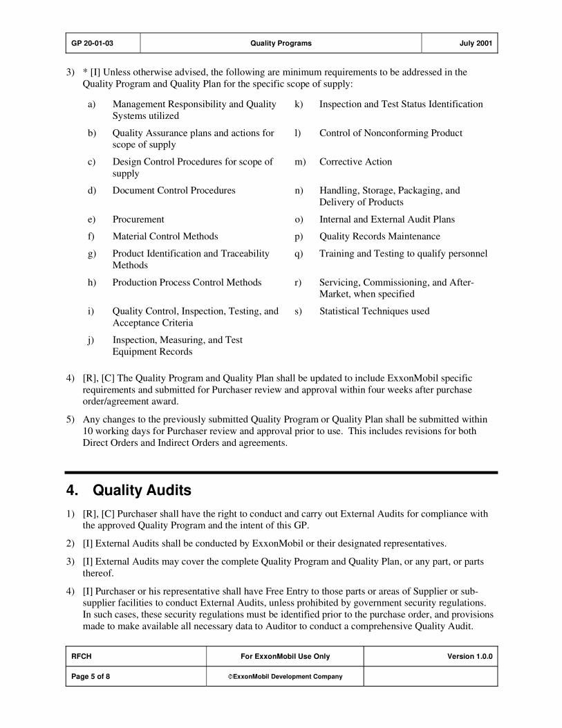
GP 20-01-03 Quality Programs July 2001
RFCH For ExxonMobil Use Only Version 1.0.0
Page 5 of 8 ExxonMobil Development Company
3) * [I] Unless otherwise advised, the following are minimum requirements to be addressed in the
Quality Program and Quality Plan for the specific scope of supply:
a) Management Responsibility and Quality
Systems utilized
k) Inspection and Test Status Identification
b) Quality Assurance plans and actions for scope of supply
l) Control of Nonconforming Product
c) Design Control Procedures for scope of
supply
m) Corrective Action
d) Document Control Procedures n) Handling, Storage, Packaging, and
Delivery of Products
e) Procurement o) Internal and External Audit Plans
f) Material Control Methods p) Quality Records Maintenance
g) Product Identification and Traceability
Methods
q) Training and Testing to qualify personnel
h) Production Process Control Methods r) Servicing, Commissioning, and After-Market, when specified
i) Quality Control, Inspection, Testing, and
Acceptance Criteria
s) Statistical Techniques used
j) Inspection, Measuring, and Test
Equipment Records
4) [R], [C] The Quality Program and Quality Plan shall be updated to include ExxonMobil specific
requirements and submitted for Purchaser review and approval within four weeks after purchase order/agreement award.
5) Any changes to the previously submitted Quality Program or Quality Plan shall be submitted within
10 working days for Purchaser review and approval prior to use. This includes revisions for both
Direct Orders and Indirect Orders and agreements.
4. Quality Audits
1) [R], [C] Purchaser shall have the right to conduct and carry out External Audits for compliance with the approved Quality Program and the intent of this GP.
2) [I] External Audits shall be conducted by ExxonMobil or their designated representatives.
3) [I] External Audits may cover the complete Quality Program and Quality Plan, or any part, or parts
thereof.
4) [I] Purchaser or his representative shall have Free Entry to those parts or areas of Supplier or sub-supplier facilities to conduct External Audits, unless prohibited by government security regulations.
In such cases, these security regulations must be identified prior to the purchase order, and provisions
made to make available all necessary data to Auditor to conduct a comprehensive Quality Audit.
GP 20-01-03 Quality Programs July 2001
RFCH For ExxonMobil Use Only Version 1.0.0
Page 6 of 8 ExxonMobil Development Company
5) [I] Compliance with approved Quality Programs, or major portions of such programs, that is deemed
unsatisfactory through External Audits by Purchaser may be cause for withholding acceptance of the
product(s).
6) [I] Auditor Safety—Supplier shall provide a safe working environment for Auditor(s) and shall alert
Auditor to all known potential hazards. If the working environment or conditions are unsafe in the
opinion of Auditor, Auditor shall not conduct the Quality Audit. Likewise, Auditor shall be
knowledgeable of and comply with Supplier safety rules.
GP 20-01-03 Quality Programs July 2001
RFCH For ExxonMobil Use Only Version 1.0.0
Page 7 of 8 ExxonMobil Development Company
Record of Change
Version 1.0.0 Date: 07/01
Location Action Description
Initial Publish.
Version 1.0.0 Date: 07/03
Global Practice version number and format updated to comply with new
process; however, original publish date remains, and no content was
modified.

GP 20-01-03 Quality Programs July 2001
RFCH For ExxonMobil Use Only Version 1.0.0
Page 8 of 8 ExxonMobil Development Company
Attachment: Purpose Codes Definitions
Code Description
C Assigned to paragraphs containing specifications whose primary purpose is reduced costs.
Reduced cost in this context refers to initial investment cost and does not include Life-Cycle
cost considerations. Life-Cycle cost considerations are captured under reliability,
maintainability, or operability purpose codes.
E Assigned to paragraphs containing specifications whose primary purpose is driven by
environmental considerations. Environmental considerations typically include specifications
intended to protect against emissions/leakage to the air, water, and/or soil. Deviations from the specifications contained in such paragraphs require formal review and approval according to
local environmental policy.
I Assigned to paragraphs that provide only clarifying information such as Scope statements,
definitions of terms, etc.
M Assigned to paragraphs containing specifications whose primary purpose is to provide for
maintainability of equipment or systems. Maintainability provisions are those that facilitate the
performance of maintenance on equipment/systems either during downtimes or during on-
stream operations.
O Assigned to paragraphs containing specifications whose primary purpose is to assure
operability of equipment or systems. Operability is the ability of the equipment/system to
perform satisfactorily even though conditions are off-design, such as during startups, process swings, subcomponent malfunction, etc.
R Assigned to paragraphs containing specifications whose primary purpose is to improve or
assure the reliability of equipment or systems. Reliability is a measure of the ability of
equipment/systems to operate without malfunction or failure between planned maintenance interventions.
S Assigned to paragraphs containing specifications whose primary purpose is avoidance of
personnel or operational safety incidents. Any deviation from the specifications contained in
such designated paragraphs requires formal review and approval according to local safety policy.
Personnel Safety: Refers to the avoidance of recordable personnel injuries; i.e., burns, cuts,
abrasions, inhalation, or exposure to dangerous substances, etc., that could result in medical treatment, restricted work, lost-time incidents, or
fatalities.
Operational
Safety:
Refers to the prevention and control of process releases, fires, explosions,
etc.