GOVERNMENT OF INDIA MINISTRY OF RAILWAYS BSC Agenda... · (ii) Clause 434.13.5 of ASME B 31.4 –...
140
भारत भारत भारत भारत सरकार सरकार सरकार सरकार रेल रेल रेल रेल मंालय मंालय मंालय मंालय GOVERNMENT OF INDIA MINISTRY OF RAILWAYS 10 एवं एवं एवं एवं 11 नवबर नवबर नवबर नवबर 2016 को को को को गोवा गोवा गोवा गोवा मममम होने होने होने होने वाल वाल वाल वाल प ु ल प ु ल प ु ल प ु ल एवं एवं एवं एवं संरचना संरचना संरचना संरचना मानक मानक मानक मानक समत समत समत समत क क क क चौरासी चौरासी चौरासी चौरासीवीं वीं वीं वीं बैठक बैठक बैठक बैठक क क क क काय"स ू ची काय"स ू ची काय"स ू ची काय"स ू ची Agenda of Eighty Fourth Meeting of Bridge & Structures Standards Committee (10 th & 11 th November - 2016) At Goa अन ु स%धान अन ु स%धान अन ु स%धान अन ु स%धान अभक’प अभक’प अभक’प अभक’प एवं एवं एवं एवं मानक मानक मानक मानक संगठन संगठन संगठन संगठन, लखनऊ लखनऊ लखनऊ लखनऊ-226011 RESEARCH DESIGNS AND STANDARDS ORGANISATION LUCKNOW-226011
Transcript of GOVERNMENT OF INDIA MINISTRY OF RAILWAYS BSC Agenda... · (ii) Clause 434.13.5 of ASME B 31.4 –...

भारतभारतभारतभारत सरकारसरकारसरकारसरकार रेलरेलरेलरेल मं�ालयमं�ालयमं�ालयमं�ालय
GOVERNMENT OF INDIA MINISTRY OF RAILWAYS
10 एवंएवंएवंएव ं11 नव�बरनव�बरनव�बरनव�बर 2016 कोकोकोको
गोवागोवागोवागोवा म�म�म�म� होनेहोनेहोनेहोने वाल�वाल�वाल�वाल�
पुलपुलपुलपुल एवंएवंएवंएवं संरचनासंरचनासंरचनासंरचना मानकमानकमानकमानक स�म�तस�म�तस�म�तस�म�त क�क�क�क�
चौरासीचौरासीचौरासीचौरासीवींवींवींवीं बैठकबैठकबैठकबैठक क�क�क�क� काय"सूचीकाय"सूचीकाय"सूचीकाय"सूची
Agenda of Eighty Fourth Meeting of
Bridge & Structures Standards Committee (10th& 11th November - 2016)
At Goa
अनुस%धानअनुस%धानअनुस%धानअनुस%धान अ�भक'पअ�भक'पअ�भक'पअ�भक'प एवंएवंएवंएवं मानकमानकमानकमानक संगठनसंगठनसंगठनसंगठन, लखनऊलखनऊलखनऊलखनऊ-226011 RESEARCH DESIGNS AND STANDARDS ORGANISATION
LUCKNOW-226011

SUBJECT INDEX Contents
I. ITEM No. 1060: Use of Corrosion Resistant Reinforcement. ........................................... 3
II. ITEM No. 1061: Provision of Horizontal Directional Drilling (HDD) Method for
pipeline crossing under railway track. .............................................................................. 7
III. ITEM No. 1062: Policy on maintaining of road and allied systems for Limited Height
subways/ Road Under Bridges. ..................................................................................... 11
IV. ITEM No. 1063: Reduction in water way of bridges. ...................................................... 13
V. ITEM No. 1064: Consideration of Future Tracks during Finalization of GAD of
ROB’s. ........................................................................................................................... 15
VI. ITEM No. 1065: Load Test for steel girders. .................................................................. 17
VII. ITEM No. 1066: Standardization of drawing for modification of 18.3m plate girder
to drawing no RDSO/B-1529 for MBG loading 1987. ..................................................... 23
VIII. ITEM No. 1067: Inspection proforma for PSC Girders. .................................................. 28
IX. Item No. 934/84th: Criteria for safe load on arch bridge. ................................................. 34
X. Item No. 995/84th: Revision of fatigue provisions in IRS Steel Bridge Code. .................. 37
XI. Item No. 1006/84th: Guidelines on Seismic Design of Railway Bridges. ......................... 62
XII. Item No. 1024/84th: Inclusion of provision of HSFG Bolt in IRS Steel Bridge Code. ....... 64
XIII. Item No. 1025/84th: Standard Drawings for FOB’s. ........................................................ 67
XIV. Item No. 1038/8th: Yardsticks for Bridge Organisation. .................................................. 68
XV. Item No. 1040/84th: Technical guidelines for Box Pushing technique. ............................ 69
XVI. Item No. 1042/84th: Periodicity of changing of oil in oil bath for roller bearing. ............... 70
XVII. Item No. 1045/84th: Introduction of Higher spans and skew angles in ROB
drawings. ....................................................................................................................... 72
XVIII. Item No. 1047/84th: Formulae for the estimation of scour depth at bridge piers. ............ 73
XIX. Item No. 1050/84th: Working of BCM through ballasted deck. ........................................ 74
XX. Item No. 1053/84th: Buoyancy Effect for Design of Foundation and Substructures. ....... 75
XXI. Item No. 1054/84th: Standard Inspection Arrangement for Bridges. ............................... 76
XXII. Item No. 1055/84th: Revision of Standard list of tools and equipment for inspection
of bridges. ..................................................................................................................... 79
XXIII. Item No. 1057/84th: Percentage of passive earth pressure to be taken in design
and analysis of well foundation. ..................................................................................... 80
XXIV. Item No. 1059/84th: Provision of Shrinkage and Temperature reinforcement in
Concrete Structures. ...................................................................................................... 81

84thMEETING OF BRIDGE AND STRUCTURES STANDARDS COMMITTEE (November 2016)
Item No 1060 Page 3
ITEM No. 1060: Use of Corrosion Resistant Reinforcement.
BSC Reference : Nil
RDSO File No. : CBS/CODES/REVEIW
Agenda : To make provisions regarding use of Corrosion Resistant ReinforcementinIndian Railway StandardCode of Practice For Plain, Reinforced & Prestressed Concrete For General Bridge Construction (Concrete Bridge Code).
NOTES BY SECRETARY
As per Railway Board’s instruction vide letter no. 2015/CE-III/BR/RDSO/Misc. dated 21.04.2016, this subject is to be deliberated in the BSC.
A. Brief History-
1.0 Prevention of corrosion in reinforcement (within the codal life) is essential for overall durability of RCC/PSC structures. The chronological development in this regard is as below.
2.0 Initial provision- Relevant part of Clause 7.1.4.6 in IRS: CBC-1997 as existed initially regarding prevention of corrosion in reinforcement is reproduced as under:-
“Special precaution like coating of reinforcement may be required in very severe exposure condition. Specialist literature may be referred to in such cases. Such coatings should be applied after removing any rust or loose material from reinforcement.”
At that time four exposure conditions were envisaged namely Mild, Moderate, Severe and Very Severe.
3.0 BS-14 (Durability of Concrete structures) - After detailed deliberations, A&C-1 to IRS-CBC (1997) was issued on 26.04.2000 in which Clause7.1.4.6 was replaced by new clause 7.1.5 as under.
“7.1.5 Protective Coatings: - In order to offer adequate resistance against corrosion, reinforcement bars shall be provided with suitable protective coating depending upon the environmental conditions. The recommended coatings are as under:

84thMEETING OF BRIDGE AND STRUCTURES STANDARDS COMMITTEE (November 2016)
Item No 1060 Page 4
Aggressive Environment
(Severe, Very severe and Extreme)
Non aggressive environment
(Mild and Moderate)
Important and major bridges
Minor bridges and structures
All structures
Cement Polymer composite coating
Or
Fusion bonded Epoxy Coating
Cement Polymer composite coating
Or
Inhibited cement slurry coating
Truncated inhibited cement slurry coating
4.0 ME’s observation - In terms of the then ME’s observation on the provisions of the coating vide Note No. 2005/M.E/Notes/29 dt 07.12.2005, the then provisions of IRS-CBC were revised and A&C slip no. 8 to IRS CBC-1997 dated 15.02.2006 has been issued. The modified provisions of Clause 7.1.5 of IRS CBC are as under,
7.1.5 Protective Coatings: - In order to offer adequate resistance against corrosion, reinforcement bars may be provided with suitable protective coatings depending upon the environmental conditions. In aggressive environments (severe, very severe and extreme) application of cement slurry coating after removal of rust and other loose material from the surface of the reinforcement bar will generally be sufficient. However, specialist literature may be referred to in extreme exposure condition.
5.0 Also vide A&C No. 2 to IRS CBC (Reprint Sept-2014) dated 14.01.2015 additional provision of concrete coating has been made vide Clause No 5.4.7 to provide adequate protection against corrosion of embedded Steel/Material. The frequency of coating shall depend upon the condition of existing coating.
6.0 Provisions in IRC: 112-2011 (Code of practice for Concrete Road Bridges) - Provisions regarding products with improved corrosion resistance vide clause 6.2.3 of IRC: 112-2011 are as under.
6.2.3 Products with improved corrosion resistance
Reinforcing steel bars with improved corrosion resistance by any of the methods described in section 18 can be used as reinforcement provided they meet the minimum strength, proof stress and elongation characteristics as specified in Table 18.1.
The design properties are considered to be the same as per Clause 6.2.2 except as given in Clause 6.2.3.2 for epoxy coated reinforcement.

84thMEETING OF BRIDGE AND STRUCTURES STANDARDS COMMITTEE (November 2016)
Item No 1060 Page 5
6.2.3. Galvanized reinforcement
The strength as well as elongation and bond properties of galvanized reinforcement are not adversely affected by galvanizing.
6.2.3.2 Epoxy-coated reinforcement
Reinforcing bars conforming to IS 1786 can be coated by fusion bonded epoxy conforming to IS 13620-1993.
The bond of coated reinforcement is lowered by upto 20 percent of that of uncoated reinforcement. In detailing of steel the lap length and anchorage lengths given in Section 15 should be increased by 25 percent.
6.2.3.3 Stainless steel reinforcement
Properties of stainless steel reinforcement shall not be inferior to the carbon steel reinforcement of corresponding strength class. For bond properties reference should be made to the relevant code or established on basis of tests.
Note: The Indian Standard for stainless steel reinforcement is under preparation. The British Standard BS: 6744:2001, which covers suitable stainless steels for use as reinforcement may be referred.
7.0 RDSO Remarks:-
Existing provisions in IRS CBC seems to be adequate if proper cover (with proper quality/impermeability) along with proper concrete coating (at required frequency) is ensured and further coating of reinforcement is not warranted due to reasons tabulated below.
Reinforcement Coating Concrete Coating
Pros 1. Is beneficial only if other protection measures like cover etc. fail within the codal life else it will be redundant.
1. It will always be beneficial for cover & reinforcement both.
2. No reduction in Bond Strength
3. Relatively Cheap
4. Open
5. Accessible
6. Repairable/Replaceable
Cons 1. Relatively Costly
2. It may reduce Bond Strength.
3. Hidden
4. Inaccessible
Nil

84thMEETING OF BRIDGE AND STRUCTURES STANDARDS COMMITTEE (November 2016)
Item No 1060 Page 6
5. Non-repairable/replaceable
However only in extreme exposure conditions based on specific technical requirement provisions of IRC 112-2011 may be adopted based on techno economic justification.
8. Committee may please deliberate.
**********

84thMEETING OF BRIDGE AND STRUCTURES STANDARDS COMMITTEE (November 2016)
Item No 1061 Page 7
ITEM No. 1061: Provision of Horizontal Directional Drilling (HDD)
Method for pipeline crossing under railway track.
BSC Ref. : Item No. 863 of 72nd BSC & Item No. 1021 of 80th BSC
RDSO File No. : CBS/DCP-1
Agenda : To make provisions for Horizontal Directional Drilling Method in pipeline crossing under railway track.
NOTES BY SECRETARY
Indian oil corporation Ltd. vide letter No. PL/HO/CONST/GENERAL/1.0 dated 12.7.16 & 04.10.16 has raised the following issue:
1. With the advancement of technology and experience gained internationally and within the country in particular, pipeline crossings across perennial rivers, National Highways, Canals and other such locations are currently being undertaken adopting the “Horizontal Directional Drilling” (HDD) technique. The HDD technique is an advance and trenchless method of executing Pipeline crossings.
Presently, the concerned agencies for all crossings under railway track obtain necessary approval & permission from concerned Divisional Railway Manager (DRM) before pipeline laying. DRM office issues approval & permission accordingly, as per guidelines of BS-105.
While laying the pipeline by Bored Cased Crossing method, following disadvantages have been observed as reported by IOCL:
i. Requires different size augers and cutting head for different casing size.
ii. In the case of soils with boulder greater than 0.3 times the casing diameter, this method cannot be used.
iii. Short drive lengths < 100m
iv. Groundwater dewatering and protection of the pit from earth collapsing may be required.
v. Grade and alignment control is difficult.
vi. In rocky strata, outer surface of casing pipe gets damaged.
vii. A larger entrance pit than pipe ramming.
viii. There is always a chance of shorting of casing & carrier pipe.
ix. Ingress of water inside casing pipe causing corrosion of pipes.

84thMEETING OF BRIDGE AND STRUCTURES STANDARDS COMMITTEE (November 2016)
Item No 1061 Page 8
x. Difficulty in extension of casing length in case of widening required as per railway’s requirement
2. Based on the literature study undertaken by RDSO, the existing provisions of Pipeline crossings under Railway track conveying inflammable substances like petroleum, oil and gas etc is given below:
(i) Clause 1.3.3 of Report BS: 105
Except for pipeline crossings covered under category A(1) above, all pipes conveying water, sewerage, non inflammable or inflammable substances should be laid under the Railway track through a casing pipe of RCC, PSC or steel of adequate strength to facilitate their maintenance and renewals without causing interference to railway traffic. The nominal diameter of the casing pipe should be sufficiently large to permit easy withdrawal of the carrier pipe without disturbing the formation. Where carrier pipes are not used, for Example telephone wires/TV cables etc as covered under category A(1), the casing pipe of suitable material and adequate size should be provided.
(ii) Clause 434.13.5 of ASME B 31.4 – 2009
Directionally Drilled Crossings: Written plans shall be developed for all directionally drilled crossings or for when directional drilling is selected as a pipe lay method. Plans will include the following:
a. Crossing plan and profile drawings showing all pipelines, utilities, cables, and structures that cross the drill path, are parallel to and within 100 ft (30 m) of the drill path, and that are within 100 ft (30 m) of the drilling operation, including mud pits and bore pits.
b. Damage prevention plan to reduce the likelihood of damage to adjacent underground facilities, including pipelines, utilities, cables, and other subsurface structures. The plan shall consider the accuracy of the method to be employed in locating existing structures and in tracking the position of the pilot string during drilling. Consideration should be given to having an auxiliary location system to include manual excavation to ensure that the drilling bit or reamer is following the projected path and does not encroach upon crossing or parallel lines. The damage prevention plan should provide specific instructions regarding the notification of affected parties including the participation in one-call systems where applicable.
c. Written safety plan to include contingency plans in the event the drilling string impacts subsurface facilities. The safety plan should identify facilities and resources to be utilized in the event of an emergency or any personnel injuries. The safety plan shall be reviewed on site with all construction personnel prior to the commencement of drilling operations.
d. Plan for containment and disposal of drilling fluids, if used.

84thMEETING OF BRIDGE AND STRUCTURES STANDARDS COMMITTEE (November 2016)
Item No 1061 Page 9
e. Hydrostatic test plan that should consider pretesting of the fabricated string(s) prior to installing the crossing. The following publications provide guidance on design of directionally drilled crossings:
(1) American Gas Association PR-227-9424“Installation of Pipelines by Horizontal Directional Drilling, An Engineering Design Guide”.
(2) American Society of Civil Engineering, Practice No. 89 — “Pipeline Crossings Handbook”
(3) Directional Crossing Contractors Association publications “Guidelines For a Successful Directional Crossing Bid Package,” “Directional Crossing Survey Standards,” and “Guidelines for Successful Mid-Sized Directional Drilling Projects”
(iii) IOCL has submitted the outcome of study carried out through IIT, Madras (IITM) to verify the pipeline against the soil surcharge and Rail loads, as the pipeline is not protected by the casing pipe. IITM has verified that the method of laying pipeline by HDD method is safe and stresses are within limits, maximum effective combined stress (Seff) for three pipes of different diameter is given in table-I. However, verification report of IITM is available in soft copy as well as hard copy which may be shared if required.
Table-I
SN
Description
Maximum Effective Combined Stress (Seff)
MPa
Maximum Value of
Seff (MPa)
Allowable Stress (0.9 x Specified Minimum
Yield Strength)
(MPa)
For diameter of pipe (mm)
508 356 324
1 Hydro- testing Condition
158.3 138.3 136.2 158.3 288.0
2 Operating Condition
152.4 135.3 133.6 152.4 288.0
3. RDSO remarks:
i. Other similar agencies like ONGC, GAIL executing the work of pipeline crossing should be consulted before finalization of modification.

84thMEETING OF BRIDGE AND STRUCTURES STANDARDS COMMITTEE (November 2016)
Item No 1061 Page 10
ii. For corrosion, higher wall thickness & 3LPE coating (3mm) has been suggested by IOCL in place of existing cathodic protection system. Since the existing anti corrosion system for steel casing pipes greater than 350mm dia. was finalized and approved by M&C Directorate of RDSO, thus proposal should also be sent to M&C Dte. for their views/approval regarding corrosion.
iii. The carrier pipe shall be designed to latest approved Railway loading standard as per IRS Bridge Rulkes or else the depth of carrier pipe shall be where stresses due to railway loading does not affect the pipe. The detailed design calculations for carrier pipe shall be submitted by concerned agency to CBE.
iv. Subject to the above, alterations can be made to BS-105 for pipeline crossing without casing pipe.
4. Committee may please deliberate.
**********

84thMEETING OF BRIDGE AND STRUCTURES STANDARDS COMMITTEE (November 2016)
Item No 1062 Page 11
ITEM No. 1062: Policy on maintaining of road and allied systems for
Limited Height subways/ Road Under Bridges.
BSC Reference : Nil
RDSO File No. : CBS/LUSW
Agenda : Policy on maintenance of road passing through sub-ways, lighting arrangement, drainage arrangement, diversion road and other allied works connected with subways and to make subways free from water logging.
NOTES BY SECRETARY
CBE/SECR has proposed the issue regarding drainage problems in RUBs and further stated that;
1. Vide ED (B & S) – II, Railway board’s letter no. 2006/CE-IV/Misc/2 (RUBs) dated 18.04.2012, Board has issued guidelines that, level Crossings which do not qualify for sanction of ROB on cost sharing basis in terms of para 925 of IRPWM, can be planned for elimination by subways at Railway’s cost. It has also been stated in the letter that, the responsibility for the maintenance of the road passing through the subway, lighting, drainage system, diversion road and any other allied works will rest with State Govt.
2. Chief Secretary of Govt. of Chhattisgarh, Maharashtra, Odisha and Madhya Pradesh were approached to issue directions towards the above matter of maintenance of road, lighting, drainage etc. In response, only Govt. of Chhattisgarh have issued instructions that too only to Municipal Commissioners for arranging maintenance of road passing through the subway, lighting arrangement, drainage etc. (Principal Secretary, Department of Town administration and Development, Govt. of Chhattisgarh’s letter dated 31.07.2012). But, no directions have been issued by Govt. of Maharashtra, Odisha and Madhya Pradesh. This is resulting into serious drainage problems in RUBs during rainy season.
3. A letter was again written to Board vide PCE/SECR’s letter No. SERC/HQ/Engg./RSW/Policy/03/Mtc/31 dated 06.05.2014 to withdraw the condition stipulated in Board’s letter dated 18.04.2012 regarding “responsibility for the maintenance of the road passing through the subway, lighting, drainage system, diversion road and any other allied works.”
4. In response, EDCE (B&S)-II, Railway Board vide letter 2014/CE-IV/Misc./21 dated 12.06.2014 did not agree the proposal of SECR to withdraw the above responsibility from State Govt. and it was reiterated that, the “responsibility for
84thMEETING OF BRIDGE AND STRUCTURES STANDARDS COMMITTEE (November 2016)
Item No 1062 Page 12
the maintenance of the road passing through the subway, lighting, drainage system, diversion road and any other allied work will rest on State Govt. only”.
5. As a result, lot of drainage problems are faced in subways involving pumping, in many cases, Railways are forcing out the water by pumping through emergency methods. No permanent solution has been arrived at owing to Board’s above guidelines.
6. The issue needs to be addressed for which a policy/MOU needs to be issued from Railway Board.
7. Alternative/innovative arrangement made by other Railways for drainage of water may also be shared.
RDSO Remarks:
A) To analyze the problems regarding water logging, settlement of track, erosion of banks and construction method/techniques and to suggest the improvement in the design etc. and to deal with any other technical issue, Adviser/Bridge/Railway Board has nominated a committee vide Railway Board letter no. 2016/CE-IV/LX-ROB/RUB (Innovations) dated: 20.09.2016 consisting of following officers.
i. Shri A. K. Singhal, EDCE (B&S), Railway Board, New Delhi ii. Shri Kailash Singh, ED (Structures) RDSO, Lucknow iii. Shri R. N. Sunkar, CBE WCR, Jabalpur iv. Shri M. P. Singh, CBE, NR, New Delhi
B) Maintenance of roads, lighting, etc are a policy matter and suggestions may be given on this.
C) The suggestions may be submitted to the committee by Zonal Railways on alternate/innovative arrangements for drainage of water.
8. Committee may please deliberate upon the item.
**********

84thMEETING OF BRIDGE AND STRUCTURES STANDARDS COMMITTEE (November 2016)
Item No 1064 Page 13
ITEM No. 1063: Reduction in water way of bridges.
BSC Ref. : Nil
RDSO File No. : CBS/PSBC
Agenda : Percentage criteria for the waterway reduction in clause 4.5.9 of Bridge Substructure and Foundation Code should be modified.
NOTES BY SECRETARY
This subject matter has been raised by the CBE/WCR for Modification in the clause 4.5.9 of Bridge Substructure and Foundation Code. It was also discussed in the CBE’s seminar held on 06th& 07th Oct.’2016 as item No.2 (a) and concluded that WCR will prepare the check list and send it to RDSO. RDSO will check/modify and circulate it to Zonal Railways for implementation.
Existing clause 4.5.9 of Bridge Substructure and Foundation Code
4.5.9 For strengthening existing bridges by jacketing etc., a reduction in waterway area as per the limits specified below may be allowed by the chief Bridge Engineer provided that there has been no history of past incidents of overflow/ washout/excessive scour etc. and that measures for safety as considered necessary by the field Engineer and approved by CBE are taken.
S.No. Span of Bridge Reduction in waterway area allowed as %age of existing waterway
1. Upto and including 3.05m 20%
2. 3.05m to 9.12m (including) Varying linearly from 20% to 10%
3. Greater than 9.12m 10%
Further reduction in the area shall be subject to CRS sanction and submission of detailed calculation of waterways etc. Where the clearances are not available, the bridge should be rebuilt.
Background of the existing clause 4.5.9
• The item “to reduce waterway during strengthening of bridges by RCC jacketing” was discussed as item no. 897 during 74th BSC held in 2003.
• CBE/ER has referred the problem of strengthening/rehabilitation of the arch bridges where HFL is high. He has opined that CBE’s may be authorized to condone resultant reduction in waterway due to such jacketing where HFL is
84thMEETING OF BRIDGE AND STRUCTURES STANDARDS COMMITTEE (November 2016)
Item No 1064 Page 14
high, since a small reduction in waterway may not necessarily cause damage to the bridge in case of flood. To account for small reduction in waterway, additional safety measures like provision of flooring, pitching of approach bank etc. can be specified.
• Based on the Committee Recommendation and Railway Board Order of the item no. 897 of 74th BSC, clause 4.5.9 was inserted in Bridge Substructure and Foundation Code.
Views of CBE/WCR
• Instead of percentage criteria, the waterway reduction should be related to the size of the bridge and headroom available above the danger level as well as CHFL keeping safety margin over that also. The para 4.5.9 of substructure code may be modified as under:
(a) Revised HFL (CHFL) with reduction in waterway after proposed rehabilitation has to be calculated. Rehabilitation should only be allowed if standard clearance and freeboard as per clause 4.8 and clause 4.9 of substructure code are available with revised HFL after rehabilitation.
(b) Subject to para (a) above, the protection work including toe wall, pitching upto HFL, retarder/energy dissipater, curtain wall, droop wall, river training works/protection works as required may be provided as per site requirement to be suggested by Executive Officer and to be approved by CBE.
(c) In case, with revised HFL, standard free board and clearance are not available then additional opening with toe wall, pitching and river training/protection work to be provided.
(d) In case above suggested additional opening work is delayed for any reason, the bridge should be declared as vulnerable bridge till such time additional opening is made.
(e) In case of minor bridges, however, depending upon the type of strata and site observed velocity of water, only protection work can be done.
RDSO Remarks:-
• CBE should be competent to reduce the waterway after assessing individual cases based on the actual site condition and he should take further decision by considering the past 50 years flow records also.
Committee may please deliberate upon the item.
**********

84thMEETING OF BRIDGE AND STRUCTURES STANDARDS COMMITTEE (November 2016)
Item No 1064 Page 15
ITEM No. 1064: Consideration of Future Tracks during Finalization of
GAD of ROB’s.
BSC Ref. : Nil.
RDSO File No. : CBS/DRB/Part BSC.
Agenda : Issue of Consideration of Future Tracks during Finalization of GAD of ROB’s.
NOTES BY SECRETARY
1. Broad guidelines for preparation of General Arrangement Drawings (GAD’s) of Road Over Bridges (ROB’s) were issued by Railway Board vide their letter No. 2011/CE-III/DE/ROB dated 21/11/2011 & letter no. 2015/CE-IV/ROB/76 dated 04/03/2015. It was instructed that Railway should finalize the GAD in such a manner so that involvement of Railway land should be minimum and generally piers/abutment should be avoided within the Railway land to avoid the hindrance to any further expansion of yard/track etc.
2. However, it has been observed that on unimportant lines and where Railway boundary is large, construction of via-duct over the whole Railway land is not economically desirable.
3. Para 1816 (iv) Engineering Code states that cost of Bridge Structure for Crossing additional tracks in future has to be borne by Railways. Para is reproduced in verbatim as follows:-
“If provision is required to be made in the bridge structure for crossing additional railways tracks in future, the cost of such extra length of the bridge structure will be borne by Railway in addition to its share of the cost for the rest of the bridge and its approaches. If the provision for extra tracks is already a sanctioned scheme or included in the Works Programme the cost of extra length of bridge on that account shall also be shared on a 50:50 basis between the Railway and Road Authority.”
4. Railway Board vide its letter No. 2015/CE-IV/ROB/76 dated 02-03-2016 proposed that Railway should finalize the GAD on guidelines as given below:-
(i) On ‘C’ Routes and Yards, preferably via-duct should be planned over the complete Railway Land.
(ii) On National Highway, State Highway, DFC Route, ‘A’ & ‘B’ routes, via-duct should be planned considering the existing tracks, sanctioned tracks and 4 more tracks for future expansion.

84thMEETING OF BRIDGE AND STRUCTURES STANDARDS COMMITTEE (November 2016)
Item No 1064 Page 16
(iii) On all ‘D Spl’, ‘D’, ‘E Spl’ and ‘E’ routes, via-duct should be planned covering existing track plus three future tracks.
On the remaining portion of Railway land, RE/Earthen embankment should be planned due to economical consideration, Slopes for the approaches should be started at the Railway Boundary.
5. Railway were asked to give their suggestions on above mentioned proposal so that a comprehensive policy on the subject matter can be issued. Railway Board advised vide their letter dated 25-10-2016 that this issue should also be deliberated during the BSC.
6. RDSO after consideration is suggesting that span arrangement should be such that it covers.
Existing Tracks + Sanctioned Lines + One Future Line + on either side
One Future span of 24m on either side (if Land available)
Above to be provided if sufficient Railway Land is available and on the remaining portion of Railway land, RE/Earthen embankment should be planned due to economical consideration, Slopes for the approaches should be started at the end of Future span of 24m.
If Railway Land is restricted then arrangement should be such that whole Railway Land is covered.
7. Committee may deliberate and make recommendations.
**********

84thMEETING OF BRIDGE AND STRUCTURES STANDARDS COMMITTEE (November 2016)
Item No 1065 Page 17
ITEM No. 1065: Load Test for steel girders.
BSC Reference : Nil
RDSO File No. : CBS/DPG/1
Agenda : To make provisions regarding static/dynamic load testing of steel girders and specifying procedure for the load tests.
NOTES BY SECRETARY
Vide letter no W-3/65/09/RB & RDSO/Pt. II/111 Dated 11.02.2016, CBE ECR has raised the issue of static/dynamic load testing of steel railway bridges. He has raised the following important issues:
1. The strength of steel bridges existing on the system viz, underslung, open web, plate and composite girders is primarily judged by measurement of camber and quality of rivets. Normally no load tests are performed.
2. Newly constructed bridges are sometimes assessed for strength by passing loaded goods trains.
3. If, however, the bridge is not connected with railway network, testing by trains is not possible.
4. Static load tests are being insisted before allowing traffic over the steel bridges, but there is no mention of load tests in railway codes/ manuals, for which no standard practices are also not available. IRC-51 is available, which gives methodology of load tests for road bridges.
5. Therefore, this item has been proposed to devise a methodology for static/dynamic load testing on steel railway bridges.
Work Done by RDSO-
1.0 Codes/ Manuals: RDSO has studied the following codes/manuals
1.1 IRC SP-51 and IRC SP-37,
1.2 “Guideline for Load and Resistance Assessment of Existing European Railway Bridges” issued as part of Sustainable Bridges by European Commission,
1.3 BS-5400 — Part 8 “Steel, concrete and composite bridges: Recommendations for materials and workmanship, concrete, reinforcement and prestressing tendons”,
84thMEETING OF BRIDGE AND STRUCTURES STANDARDS COMMITTEE (November 2016)
Item No 1065 Page 18
1.4 Inspection manual – Texas Department of Transportation. (Inspection manuals of Connecticut, Delaware also seen but these are all US highway manuals, so only one is referred to.
1.5 AS-5100.7-2004 “Rating for Existing Bridges”.
1.6 BA 54/94 “Load testing for bridge assessment”, issued by The Highways Agency, Scotland.
1.7 IRS Concrete Bridge Code.
1.8 Load tests for piles, IS:2911.
2.0 Case Studies: RDSO has studied few case studies of load testing being deployed on bridges and the conclusions drawn thereon:
2.1 Load testing of the new Svinesund Bridge, by Raid Karoumi and Andreas Andersson, Royal Institute of Technology (KTH), Department of Civil and Architectural Engineering, Division of Structural Design and Bridges, Stockholm, Sweden, 2007.
2.2 Research report no UMCEE 96-10 on “Load Testing of Bridges”, submitted to Michigan Department for Transportation and The Great Lakes Center for Truck and Transit Research, by Andrej S. Novak and Vijay K. Saraf, University of Michigan.
3.0 Conclusions which can be drawn based on various documents studied:
3.1 Static load test is used as a tool for assessing load carrying capacity of bridges. The procedure for assessing the load carrying capacity of old bridges for the purpose of ascertaining safety and for upgrading the bridges for higher loads is given in the codes.
3.2 Performance static load tests, within normal live load regular operations are sometimes used, but are generally not considered reliable. (Para 6.3.4 of AS 5100.7-2004; Section 5, Bridge Inspection Manual Texas DOT) Proof load tests with loads exceeding the permitted live loads are considered a good tool to physically verify the reserve strength of bridges and utilize part of same for commercial operations. This approach might not be suitable for railway operations where fatigue is governing in majority of cases.
3.3 None of the codes, however, specifies load test for ascertaining the quality of new construction, as is sought in Indian Railways.
3.4 Dynamic load tests are used to collect information about the natural frequency and resonance behaviour for better understanding of behaviour of the structure.

84thMEETING OF BRIDGE AND STRUCTURES STANDARDS COMMITTEE (November 2016)
Item No 1065 Page 19
3.5 Load test is used generally in conjunction with the instrumentation, so that the conclusions drawn on the basis of instrumentation measurements are verified through deflection measurements. This helps in eliminating errors associated with fixing of gages and data collection etc.
4.0 Limitations of Static Load Tests: For steel structures, static load tests suffer from several limitations, enumerated below:
4.1 Steel is an elastic, factory made product and its ductility is not in doubt. The problems associated with fabrication which are often sought to be verified through load tests come into play only under repeated applications of loads (Fatigue). One time application of load in load test is not the right tool for verifying the quality of fabrication.
4.2 Static load test using sand bags or other materials as kenteledge is a cumbersome procedure and the amount of load required even for loading a mid-sized girder for its live load capacity is often difficult, especially since space availability in Railway girders is limited due to lesser width. As a result, the full elastic behaviour of girder might not be possible to be verified through load tests.
4.3 If train vehicles are used for static load test, if the static load applied is not precisely known, the deflection worked out might be erroneous and can lead to wrong conclusions.
4.4 Establishing independent reference to measure the deflection using dial gauge or scale system is not possible at all locations and this means that the shore spans where height is less and water not present are the often default choice for carrying out the load tests. This reduces the efficacy of load test.
4.5 Steel structures have sufficient residual strength beyond elastic limit and, in many structures, alternate load paths are available. Even if load on structure exceeds the elastic limit of some part, the same might not fully reflect in the deflection. Due to simplifying assumptions such as pin-jointed trusses, zero fixity at ends, ignoring the effect of track continuity and 2-D behaviour of girders, the theoretical deflection computed is often higher than actual deflection of the structure. Comparing the actual field measurements of static load test with theoretical computations often lead to erroneous conclusions.
4.6 For long span bridges, dead load and superimposed dead load itself is a substantial component of the entire load carrying capacity. In this scenario, live load component might not be significant for the overall girder (Though it is still important for some individual components). For such girders, the camber values immediately after launching and after providing superimposed dead load might give good idea of the behaviour of structure.
5.0 Benefits of Static Load Test: Even with the above limitations, static load tests have several uses:

84thMEETING OF BRIDGE AND STRUCTURES STANDARDS COMMITTEE (November 2016)
Item No 1065 Page 20
5.1 Verification of design as to rule out gross errors. The measurements of deflection during static load test can give idea about the design on overall basis such that the gross errors can be ruled out.
5.2 Static load test is a simple test which can be performed easily in field and results can be easily interpreted. Instrumentation requires specialized agencies for conducting tests and for interpreting the results.
5.3 Static load test is an excellent physical measurement which can be used to independently verify a numerical model of bridge created for instrumentation purposes.
5.4 Static load test can help examine behaviour of old bridges which cannot be analyzed theoretically due to non-availability of detailed design and/or documentation. Similarly, the girders which are damaged due to impact/corrosion etc where the theoretical study might not be so reliable can be studied through load tests. For retrofitment, the before and after load tests give excellent indication of efficacy of retrofitment.
6.0 Limitations of Dynamic Load Test:
6.1 The dynamic load tests can be used only with instrumentation. The impact factor given in codes is a statistical value, which depends on several factors such as condition of track, condition of vehicles, operation characteristics etc which are difficult to create/replicate in field. If only deflection is measured, the errors due to unknown impact factor might make the readings difficult to interpret.
6.2 Further, impact factor is not same at all locations and stress measurements during dynamic tests at different locations on structure might show different values. Therefore, dynamic load tests can be used only to know the envelope of stresses and/or deflections.
6.3 Under dynamic load tests, the position of vehicle is not precisely known and while the peak values might be captured, meaningful conclusions about why the structure is behaving in a particular fashion might be difficult to establish without supplementary tests.
7.0 Benefits of Dynamic Load Test:
7.1 Dynamic load tests give idea about vibrations on the structure and their amplitude. Excess amplitudes are indicative of resonance and the natural frequency of structure can give idea about the speeds that can be permitted on bridge without undue vibrations.
7.2 Dynamic load tests can supplement the insights into behaviour of structure gained through numerical models/static load tests etc.

84thMEETING OF BRIDGE AND STRUCTURES STANDARDS COMMITTEE (November 2016)
Item No 1065 Page 21
8.0 Load tests have already been specified for concrete precast units in Para 18 of IRS Concrete Bridge Code. Load tests are also used for piles as per provisions of IS:2911.
9.0 The item for load tests appears in the para “18.4.7 Para-17. Procedure For Inspection Of Bridges” of Policy Circular No 7, which states that:
“(3) If the Commissioner considers it necessary, in addition to the certificate of a Bridge Engineer employed for the purpose, he can call for the Load Deflection Test under the loads for which the bridge is designed and where this is not possible under the heaviest loads available.
(4) (a) When making Card Deflection Test, the test cards are to be placed at right angles to the centre line of the track, in order to record oscillation and the recording pencil point should be as fine as possible.
(b) When central deflection is measured, allowance shall be made for the deflection, if any, of the abutments.
(5) In order to record the static deflection, the test shall be carried out at dead slow speed and at the maximum permissible speed of the section and the speed shall be carefully measured by stopwatch or by some automatic means.
(6) The actual deflection cards shall be submitted to the Commissioner together with a statement of deflections and oscillations in Form XVIII.
(7) The deflection of the girder shall be worked out theoretically and shall be shown in Column 12 of Form XVIII to enable a comparison being made with the observed deflection.
(8) In addition to the Card Deflection Test, the Commissioner may, at his discretion, require Stress Recorder Test to be carried out on any plate or open web girders of clear spans exceeding 30 metres.
(9) (a) Stress Recorder Test shall be carried out with a stress recorder of approved type.
(b) Tests loads and speeds shall be as specified for Card Deflection Tests.
(c) Tests shall be taken, on the chords or flanges at mid span and on such web and floor members as the Commissioner shall specify.
(d) If a sufficient number of instruments are available, these tests shall be made simultaneously.
(10) The stress recorder diagrams together with calculations showing how the maximum stress under the design load with full impact (including dead load stresses) is deduced from the measured stress shall be submitted to the Commissioner who shall, before sanctioning the opening of the bridge, satisfy himself that the stresses in the girders will not exceed those specified in the IRS Steel Bridge Code, 2003.

84thMEETING OF BRIDGE AND STRUCTURES STANDARDS COMMITTEE (November 2016)
Item No 1065 Page 22
(11) If the Commissioner is satisfied that the girder has been properly designed for the work it is intended to perform, then, the open web and plate girders are not required to be tested.”
The committee may kindly deliberate and decide if any elaboration/modification of the instructions given in policy circular no 7 is required.
************

84thMEETING OF BRIDGE AND STRUCTURES STANDARDS COMMITTEE (November 2016)
Item No 1066 Page 23
ITEM No. 1066: Standardization of drawing for modification of 18.3m
plate girder to drawing no RDSO/B-1529 for MBG loading 1987. BSC Reference : Nil
RDSO File No. : CBS/DPG/1
Agenda : Standardization of drawing for modification of 18.3m plate girder to drawing no RDSO/B-1529 for MBG loading 1987.
NOTES BY SECRETARY
1. CBE ER, vide his letter no W(3)/66/3/38 dated 15/03/2016 has raised the issue of excessive vibration noticed on girders built to RDSO drawing no B-1529 (18.3 m, MBG Loading 1987) during passage of heavy trains to CC+8+2 (Annexure 1066/1).
2. This matter was earlier referred to RDSO in 2010 and a solution was provided by RDSO vide letter no CBS/Insp/WBG dated 05/08.03.2010 (Annexure 1066/2). In this solution, the V-type cross-frames were considered to be weak and RDSO advised that the same may be replaced by X-type cross frames.
3. Eastern Railway has carried out this modification in all girders, however, this problem was not rectified. The matter was again referred by Eastern Railway to RDSO vide letter no W(3)/65/0/Vol.III Dated 24.02.2016.
4. RDSO carried out full design check and nit was found that the design of main girders is adequate for the 4 Million cycles criteria that was adopted during design. Even as per the new fatigue criteria, the fatigue life for these girders was found to be 40 years with simplified procedure. The actual design life if stresses are measured or if detailed design with train loading is done will be significantly higher. Therefore, the girders need not be replaced.
5. The design check, however, revealed that the top lateral bracing section provided in these girders i.e. ISA 75x75x10 is inadequate and ISA 100x100x12 is required as per computations followed for RDSO designs. The same was advised to Eastern Railway vide letter no CBS/DPG/1 Dated 11.03.2016(Annexure 1066/3).
6. Eastern railway is currently carrying out this modification is field and the result of the modification in arresting the excess vibrations shall be known soon. This problem has been reported on North Western Railway, as learnt during oral communication with some officials.

84thMEETING OF BRIDGE AND STRUCTURES STANDARDS COMMITTEE (November 2016)
Item No 1066 Page 24
7. All railways where these girders are provided need to be examined afresh and once the technical solution to the issue is found, modification of girders needs to be done.
8. The committee may deliberate the issue and decide further course of action.
*************

84thMEETING OF BRIDGE AND STRUCTURES STANDARDS COMMITTEE (November 2016)
Item No 1066 Page 25
Annexure 1066/1

84thMEETING OF BRIDGE AND STRUCTURES STANDARDS COMMITTEE (November 2016)
Item No 1066 Page 26
Annexure 1066/2

84thMEETING OF BRIDGE AND STRUCTURES STANDARDS COMMITTEE (November 2016)
Item No 1066 Page 27
Annexure 1066/3

84thMEETING OF BRIDGE AND STRUCTURES STANDARDS COMMITTEE (November 2016)
Item No 934 Page 28
ITEM No. 1067: Inspection proforma for PSC Girders.
BSC Ref : 955 (77th BSC)
RDSO File No’s : C-77 and CBS/DPC
Agenda : Inspection proforma for PSC Girders.
NOTES BY SECRETARY CBE/SWR vide letter no. SWR/W-81/BSC Meeting/Vol-II, dated 25.07.2016
proposed subject Agenda Item No. 10 for 84th BSC Meeting.
The issue of Inspection Proforma has already been deliberated in details vide item no. 955 of 77th BSC. During the deliberation of Item 955, a Proforma prepared by IRICEN was circulated as below for feedback of CBE’s, but no feedback was received.
BRIDGE No._______
DETAILS OF BRIDGE
GAUGE___________ LOCATION AT KM__________ Section___________ LINE____________________
1. Number of Spans 6. Degree of skewness
2. Span No. 7. Gradient on bridge, if any
3. Clear Span 8. Curve on bridge, if any
4. Overall Length 9. Super elevation on bridge a) In rail b) In bed block
5. Effective Span 10. Eccentricity of track w.r.t. girders
11 Detail of Girders
(a) No. of Girders per span
(b) Type of Girder
(c) Spacing
(d) Girder Depth at end
(e) Girder Depth at center
(f) Bottom width of Girder
12 Type of Decking
13 Type of construction and location/ No. of construction joints/segmental joints/junction of precast and cast-in-situ Slabs/Bracings/Diaphragms

84thMEETING OF BRIDGE AND STRUCTURES STANDARDS COMMITTEE (November 2016)
Item No 934 Page 29
14 (a) Type of bearing and Expansion arrangements
(b) Size and thickness of neoprene bearings including thickness of rubber and steel layers
(c) Restraint arrangement, if any
15 (a) Mix design used for concreting
(b) Admixtures used in concrete
(c) Special corrosion protection measures taken
(d) Type of reinforcement bars used
(e) Cover to reinforcement
(f) Wearing coat, type and thickness
16 (a) Details of Drainage arrangement
(b) Details of Ventilation arrangement
NAME OF RIVER----------------------
TERRITORIAL 1. PWI 2. AEN 3. DEN/Sr.DEN
17 Drawing No. of Girder
18 (a) Type of prestressing system and prestressing tendons used.
(b) No. & location of prestressing tendon
(c) Prestressing load on each tendon (d) Type of cable ducts used and whether grouting done
(e) Dummy Cables, if any.
19 Designed Loading Standard
20 Date of placing girders on Bridge
21 DETAILS OF TRACK ON GIRDER SPANS
(a) Number of Track & c/c tracks
(b) Type & Weight of Rail
(c) Sleepers-Size, nos. per span and date laid
(d) Expansion joints-their type and location
(e) Guard Rails (f) Location of rail joints
(g) Type of ballast and cushion
22 Depth from R.L. to top of Bed Blocks
23 Depth from R.L. to River bed level
24 Depth from R.L. to Summer water level
25 Depth from R.L. to bottom of Girder in the center of span and at end of span
26 Details of Gradients and curve on either side bridge approaches
(a) Near End (in increasing KMs)
(b) Far end
27 Type of foundation and depth from Rail level
28 Type of Abutments 29 Type of piers
30 Type and Size of Bed blocks/Pedestals
31 Details of jacking points of girder
32 (a) Type of surface coating done
(b) Painting Area

84thMEETING OF BRIDGE AND STRUCTURES STANDARDS COMMITTEE (November 2016)
Item No 934 Page 30
33 Girder weight (per span and total)
34 Location (a) Trolley refuges
(b) Safety refuges
(c) Foot-path
(d) Path-way
(e) Sand Bins
Br. No.______________
35.
R.L. to H.F.L. and Date/Dates of highest flood levels
36.
Depth from R.L. to Danger Level
37.
R.L. with respect to mean sea level.
38. Permanent Speed restrictions, if any and reasons of imposition.
39.
Previous History of Bridge
40.
Additions and alterations to original design
41.
Year of Fabrication, Name of Fabricator and Dimensioned Line sketch of Girder (End view and side view)
42. Sketches of Camber Diagram, Cable Profile
Section ----------------------------
43. CAMBER READINGS
DESIGNED CAMBER READING
INITIAL ACTUAL CAMBER READING
PANEL POINT
↓ YEAR CAMBER READINGS
44. DEFECT LIST
LOCATION OF DEFECT
REPAIRS DATE & DETAILS OF
REMARKS ON CONDITION OF DEFECT
REMARKS ON CONDITION OF DEFECT
YEAR Signature
Br. No._________
DT. OF LAST D.I.
Year, Nature And Date of Inspection. Name &Desig. Of Inspecting Official
Condition of camber & Defects in readings, if any.
Date of cleaning of bearings, Condition of Bearings and Defects
Condition of Bed Block and Defects

84thMEETING OF BRIDGE AND STRUCTURES STANDARDS COMMITTEE (November 2016)
Item No 934 Page 31
Section ________________________
Condition of Support point of Bearings & Defects
Condition of End anchorage Zone of PSC Elements and defects
Sketches of Defects/Cracks noticed.
Br. No.___________
Year, Nature And Date of Inspection
Condition of Bottom Flange and Defects
Condition of Diaphragms/Cross Girder and Defects
Condition of Top Flange/Slab including wearing coat & defects
Section_________________
Condition of Construction joints and Defects
Condition of Junction of Precast Beam & Cast-in-situ Slab and Defects
SKETCHES OF DEFECTS/CRACKS NOTICE
Br. No._____________
Year, Nature and Date of Inspection
Condition of Expansion Joints and Defects
Condition of Ventilation in case of box Girder and defects
Temperature
Inside Box Outside Box
Section__________________
Condition of Web of Girder Condition of Web of Girder in End Quarter Span and defects
Condition of Area Around Drainage Pipes
Sketches Defects/ Cracks Noticed Along the
prestressing cables
In Box Girder on Interior Faces
Br. No._____________
Year, Nature and Date of Inspection
Year of painting, Type of paint, Condition of surface Protection Coating and Defects
Cracks Nos. having tell-tales
Condition of Cracks under tell-tales
Section__________________
Condition of ladders, Railings, Inspection Arrangements
Experiments and trials under observation and Miscellaneous Observations
Signature of Inspecting official
Sketches of defects/cracks noticed
Br. No.__________
Year of Inspection Recommendations of BRI on Defects Noticed
Remarks of AEN (Bridges)
Section__________
Orders of XEN (Bridges) Orders of Dy.CE(Bridges) Details of action taken on Previous years’ orders.
RDSO vide letter no CBS/DPC dated 15-07-2009 submitted its views on the same to the Railway Board. The RDSO’s views emphasize that the provisions of IRBM are sufficient and cover almost all the items mentioned in the IRICEN Proforma.

84thMEETING OF BRIDGE AND STRUCTURES STANDARDS COMMITTEE (November 2016)
Item No 934 Page 32
Subsequently vide letter no CBS/DPC dated 5-11-2009, RDSO submitted a revised Proforma also to Railway Board as below.
Add new Sub-Para 1107 (15) (I) as below:
“1107 (15) (I) In case of PSC girders, if the CRN is assessed to be 1, 2 or 3 by the Inspecting Official in column no. 8 (relating to PSC Girder of standard Proforma of Bridge Inspection Register for inspection of Major and Important Bridges as per Annexure 11/9 Para 1103.4 of IR Bridge Manual), an additional inspection Proforma should be submitted by the inspecting official as per the Proforma given in Annexure 11/16 Para 1103.4 of the IR Bridge Manual.”
Alsoadd one new Annexure 11/16 para 1103.4 as under:
Annexure 11/16 Para 1103.4
Inspection Proforma for PSC girder
Division:........................... Block Section:………..…… Km Location:… …...
ADEN Sub Division:…………….. Bridge No:………………… Bridge Spans: ……..
Yea of Construction:…………….
Year and Date of inspection.
Span wise details of PSC girder & component where defects/cracks observed. (i.e. identification of particular PCS girder or / its components etc)
*Sketch of Defects/ Cracks noticed, previous history of such defect (if any) details of condition/defects/cracks /observed in PSC girder component (s) with reference to col. (2)
Signature, Name and Designation of the Inspecting Official
1 2 3 4
*The length, width and type (longitudinal/transverse/horizontal/vertical/diagonal) of the crack including its location with reference to identifiable component of the PSC girder’s and details regarding any progression of such crack in width & length assessed in previous inspection should also be indicated in the sketch. In case there is no progression observed in width and length of such crack, it should be marked as dormant crack
Add new Sub-Para 1103.4 (viii) as under: “1103.4 (viii): Proforma for inspection of PSC Girders (Annexure 11/16).”
However, as per final deliberation on Item no. 955, Railway Board ordered for an Advance Correction slip no 22 dated 28.03.2011 to Indian Railway bridge Manual (IRBM) as below:-
“(I) Replace existing Para 1107 (15) (i) in IRBM with following and renumber it as 1107(15)(b)(i):

84thMEETING OF BRIDGE AND STRUCTURES STANDARDS COMMITTEE (November 2016)
Item No 934 Page 33
1107(15)(b)(i) – In case of PSC girders, assessment of loss of camber should be done. Camber measurement should be at centre up to 20m span and at centre& quarter points for spans more than 20m. Camber measurements would be entered in column 8 of Annexure 11/9.
(II) Existing para 1107 (15) (b) is renumbered as 1107 (15)(b) (ii).”
This issue has been examined and it is found that provisions of inspection of bridges exist in Chapter 11 of Indian Railway Bridge Manual. Para 15 of IRBM is related to inspection of concrete bridges.
Modified Proforma in IRBM as annexure 11/9 (para 1103.4) will be following:-
PROFORMA FOR INSPECTION OF MAJOR AND IMPORTANT BRIDGES CONDITION OF THE BRIDGE AT THE TIME OF INSPECTION
Date of Inspection
Foundation and flooring extent of scour and damage
Masonry condition, extent of defect in substructure
Protective works and Waterway scour, slips of settlements, sanctioned reserve available and whether waterway is clear
Bed Blocks Cracks, tendency to move
1 2 3 4 5
Girder Bearings & expansion arrangement
Steel work in the case of steel/composite girder bridge structural condition and stage of painting.
PSC/Concrete/Composite girder in superstructure condition of girders/ beams, any cracks or defects noticed, condition of slabs/decks & Camber
Sleepers, Year of laying condition and renewals required
Line & Level
6 7 8 9 10
Track on bridge Drainage arrangements on ballasted deck and arch bridge
Track on approaches, Approach slabs, ballast walls & rails, earth slopes, etc.
Bearing plates & their seating
Guard rails Hook bolts
11 12 13 14 15
Other items like trolley refuges/foot paths, fire fightingequipments etc.
Action taken on last year’s notes
Initial of inspecting official and URN
Initials of higher officials with remarks
16 17 18 19
Committee may please deliberate.
*************

84thMEETING OF BRIDGE AND STRUCTURES STANDARDS COMMITTEE (November 2016)
Item No 934 Page 34
Review of action taken on pending items.
Item No. 934/84th: Criteria for safe load on arch bridge.
Ref: Item No. 934/76th/2007/CBS/DAB
COMMITTEE’S OBSERVATIONS:
Committee noted that A&C Slip has been issued to Arch Bridge Code to arrive at load carrying capacity by load testing for Arch Bridges of spans less than 4.57m.
Guidelines of Arch Bridges could not be issued as Committee could not meet during the year.
COMMITTEE’S RECOMMENDATIONS:
RDSO shall pursue to conduct meeting of committee nominated to issue guidelines for Arch Bridges.
RAILWAY BOARD ORDERS:
The issue is long pending. The committee to submit its report latest by 31.10.2015.
PRESENT STATUS:
1. In compliance to RAILWAY BOARD ORDERS on 83rd BSC, the guidelines on “Methodology of Load Testing and Calculation of Test Load for Testing of Existing Arch Bridges” has been issued vide RDSO Report No. BS 116 on 06 June 2016.
2. Railway Board vide letter No. 2003/CE-I/BR-III/6 Pt. II Dated 14.09.2016 has reconstituted a Committee for issuing guidelines regarding Assessment and Retro-fitment of Arch Bridges comprising of following members:
a. Executive Director (Structures), RDSO : Convener
b. Sr. Professor (Bridge-I), IRICEN : Member
c. Chief Bridge Engineer, Eastern Railway : Member
The committee is to finalize and issue guidelines regarding Assessment and Retro-fitment of Arch Bridges by 31st December 2016.
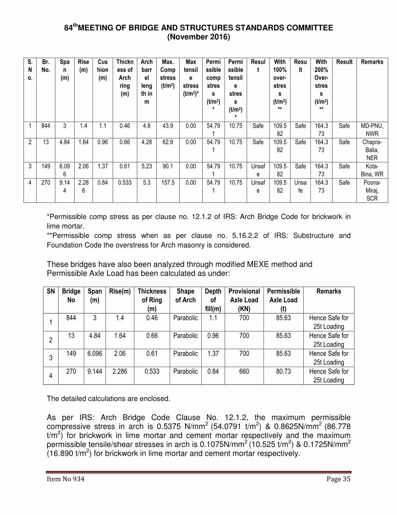
3. Accordingly, Five Arch Bridges of different Spans have been analyzed as per formula given in book on Beams, Arches and frames, Issue 1, version E1.06 from structx.com and the detailed calculations are enclosed and results are summarized as under.
84thMEETING OF BRIDGE AND STRUCTURES STANDARDS COMMITTEE (November 2016)
Item No 934 Page 35
S.
N
o.
Br.
No.
Spa
n
(m)
Rise
(m)
Cus
hion
(m)
Thickn
ess of
Arch
ring
(m)
Arch
barr
el
leng
th in
m
Max.
Comp
stress
(t/m2)
Max
tensil
e
stress
(t/m2)*
Permi
ssible
comp
stres
s
(t/m2)
*
Permi
ssible
tensil
e
stres
s
(t/m2)
*
Resul
t
With
100%
over-
stres
s
(t/m2)
**
Resu
lt
With
200%
Over-
stres
s
(t/m2)
**
Result Remarks
1 844 3 1.4 1.1 0.46 4.8 43.9 0.00 54.79
1
10.75 Safe 109.5
82
Safe 164.3
73
Safe MD-PNU,
NWR
2 13 4.84 1.64 0.96 0.66 4.28 62.9 0.00 54.79
1
10.75 Safe 109.5
82
Safe 164.3
73
Safe Chapra-
Balia,
NER
3 149 6.09
6
2.06 1.37 0.61 5.23 90.1 0.00 54.79
1
10.75 Unsaf
e
109.5
82
Safe 164.3
73
Safe Kota-
Bina, WR
4 270 9.14
4
2.28
6
0.84 0.533 5.3 157.5 0.00 54.79
1
10.75 Unsaf
e
109.5
82
Unsa
fe
164.3
73
Safe Poona-
Miraj,
SCR
*Permissible comp stress as per clause no. 12.1.2 of IRS: Arch Bridge Code for brickwork in
lime mortar.
**Permissible comp stress when as per clause no. 5.16.2.2 of IRS: Substructure and
Foundation Code the overstress for Arch masonry is considered.
These bridges have also been analyzed through modified MEXE method and Permissible Axle Load has been calculated as under: SN Bridge
No
Span
(m)
Rise(m) Thickness
of Ring
(m)
Shape
of Arch
Depth
of
fill(m)
Provisional
Axle Load
(KN)
Permissible
Axle Load
(t)
Remarks
1 844 3 1.4 0.46 Parabolic 1.1 700 85.63 Hence Safe for
25t Loading
2 13 4.84 1.64 0.66 Parabolic 0.96 700 85.63 Hence Safe for
25t Loading
3 149 6.096 2.06 0.61 Parabolic 1.37 700 85.63 Hence Safe for
25t Loading
4 270 9.144 2.286 0.533 Parabolic 0.84 660 80.73 Hence Safe for
25t Loading
The detailed calculations are enclosed.
As per IRS: Arch Bridge Code Clause No. 12.1.2, the maximum permissible compressive stress in arch is 0.5375 N/mm2 (54.0791 t/m2) & 0.8625N/mm2 (86.778 t/m2) for brickwork in lime mortar and cement mortar respectively and the maximum permissible tensile/shear stresses in arch is 0.1075N/mm2 (10.525 t/m2) & 0.1725N/mm2
(16.890 t/m2) for brickwork in lime mortar and cement mortar respectively.
84thMEETING OF BRIDGE AND STRUCTURES STANDARDS COMMITTEE (November 2016)
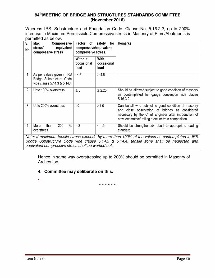
Item No 934 Page 36
Whereas IRS: Substructure and Foundation Code, Clause No. 5.16.2.2, up to 200% increase in Maximum Permissible Compressive stress in Masonry of Piers/Abutments is permitted as below. S.
No
Max. Compressive stress/ equivalent compressive stress
Factor of safety for compressive/equivalent compressive stress.
Remarks
Without occasional load
With occasional load
1 As per values given in IRS Bridge Substructure Code vide clause 5.14.3 & 5.14.4
≥ 6 ≥ 4.5
2 Upto 100% overstress ≥ 3 ≥ 2.25 Should be allowed subject to good condition of masonry as contemplated for gauge conversion vide clause 5.16.3.2
3 Upto 200% overstress ≥2 ≥1.5 Can be allowed subject to good condition of masonry and close observation of bridges as considered necessary by the Chief Engineer after introduction of new locomotive/ rolling stock or train composition
4 More than 200 % overstress
< 2 < 1.5 Should be strengthened/ rebuilt to appropriate loading standard
Note: If maximum tensile stress exceeds by more than 100% of the values as contemplated in IRS Bridge Substructure Code vide clause 5.14.3 & 5.14.4, tensile zone shall be neglected and equivalent compressive stress shall be worked out.
Hence in same way overstressing up to 200% should be permitted in Masonry of Arches too.
4. Committee may deliberate on this.
.
************
84thMEETING OF BRIDGE AND STRUCTURES STANDARDS COMMITTEE (November 2016)
Item No 995 Page 37
Item No. 995/84th: Revision of fatigue provisions in IRS Steel Bridge
Code.
Ref: Item No. 995/78th/2009/ CBS/PSB
COMMITTEE’S OBSERVATIONS:
1. RDSO has taken up design of open web girders with new fatigue provisions to better understand the same.
2. The issues discussed in 82nd BSC need to be addressed. The study needs to be completed by RDSO to decide this important item.
COMMITTEE’S RECOMMENDATIONS:
RDSO shall propose necessary correction slip.
RAILWAY BOARD ORDERS:
RDSO to propose necessary correction slips for Fatigue provisions in steel bridges after studying the design & cost implications. The item to be closed after issue of correction slip.
PRESENT STATUS:
A. RDSO has prepared an A & C slip, completely re-revising the appendix G. There are two major conceptual changes in the re-revised appendix, namely to specify and change the loads taken for fatigue assessment, and to include the fatigue assessment for existing bridges in the appendix whereas earlier appendix was for new bridges only.
B. In 82nd BSC meeting, Railway Board had given orders that
1. The impact factor to be taken for fatigue assessment shall be 50% of design impact factor.
2. The design procedure of members like diagonals which are not subject to stress reversals for full magnitude of stress variation during passage of trains shall be modified as:
a. Stress range in tension only shall be considered for fatigue.
b. 2/3rd of λ2 (factor for GMT) shall be used.
C. Railway Board had given orders that “RDSO to design a few structures with proposed revisions and then propose necessary correction slip to IRS Steel Bridge Code with necessary commentary”.
D. In 83rd BSC meeting, RDSO presented the results of few designs of open web girders. The final correction slip was to be sent by RDSO after taking into account these designs.
E. Upon further study and adequate experience gained with the fatigue design of structures with new provisions, it was seen that there is no precedence for

84thMEETING OF BRIDGE AND STRUCTURES STANDARDS COMMITTEE (November 2016)
Item No 995 Page 38
reducing the λ2 value or using stress range in tension only for fatigue design of diagonals in other codes. It was further found that the problem of increased weight could be tackled by providing HSFG bolts. Accordingly, this change has not been done.
F. Proposed A & C slip is placed at Annexure 995/1
G. Detailed comparison between the existing provisions and the proposed provisions is placed at Annexure 995/2.
H. The important changes in Appendix G (re-revised) have been made as follows (All references are to old clauses except where specifically written):
1. Major changes to the Appendix: There are two major changes in the re-revised appendix, namely to specify and change the loads taken for fatigue assessment, and to include the fatigue assessment for existing bridges in the appendix whereas earlier appendix was for new bridges only. These changes are in few paragraphs given below:
a. Clauses 6.2/12.5.1 merged and modified: These clauses have been combined to remove duplication, and to give logical flow of the ideas. This is the most important change in the revised appendix. The provisions have been modified as clauses 6.2 (New) and 6.2.1 (New) to specify the loads which are to be used for fatigue assessment. The live loads alone are to be used for fatigue assessment as per revised provisions, with 50% of impact. This problem was noticed during design of open web girder and the revised provisions are as per provisions of other codes, and as per orders of Railway Board on discussions held in 83rd BSC meeting. (The recommendations modifying design procedure for diagonal have not been found technically in order)
b. Clause 6.7 modified: Provision changed to clause 6.2.2 (New) and this now specifies actual train models to be used clearly and defines the competent authority as Chief Bridge Engineer. In the revised clause, the actual train history also allowed. This change expands scope of existing appendix from mere design to include fatigue assessment of existing bridges.
c. Clause 7/7.1.1: Revised as clauses 11/11.1/11.2(New). The earlier revised appendix G provided for new design only. These clauses permit use of field measurements for fatigue assessment. This is especially useful for working out residual life of steel structures. This change expands scope of existing appendix from mere design to include fatigue assessment of existing bridges.
d. New Clauses 8.2 to 8.6 added to Re-revised Appendix ‘G’: These clauses have been added to give step by step procedure for fatigue evaluation/design. This is minor change.
84thMEETING OF BRIDGE AND STRUCTURES STANDARDS COMMITTEE (November 2016)
Item No 995 Page 39
e. Table 9.1: Fatigue categories 7(a) and 7(b) added for check for fatigue stresses in shear. These are based on categories defined in EN:1993-1-9, details 6 and 7.
f. Clauses 10.2.1/10.2.3/10.2.4/10.2.5 rewritten: These clauses have been rearranged to explain the S-N curves properly. There was problem in understanding the repetitive language in existing clauses.
g. Clauses 12.3.2.4, 12.3.2.7, 12.3.2.8, 12.3.3 and 12.3.3.1 deleted: The appendix gives S-N curves with three slopes in different regions. These clauses were in existing appendix allowed single or dual slope curves to be used. Use of single/dual slope curves is slightly conservative and these slightly ease the computations. However, these provisions are not required in view of adequate computational efforts available nowadays, as these are more likely to create confusion. This is a minor change as it affects only cycles with low stress ranges.
h. Clause 3.6.4 of Steel Bridge Code: Revised to remove reference to Bridge Rules as loads for assessment clearly specified in re-revised appendix ‘G’.
i. Clause 3.6.5 of Steel Bridge Code: Use of other than standard life/GMT allowed with the approval of CBE.
j. New clause 3.20.4 added to Steel Bridge Code, for specifying use of re-revised appendix ‘G’ for fatigue assessment of existing bridges.
2. Clauses modified to specify competent authority: Few clauses in appendix were dependent on decision by the competent authority but the same was not specified. The same has been done in the following clauses:
a. Clause 11.1: The authority to change partial safety factors has been defined as Railway Board.
b. Clause 12.5.2.1: Reference to competent authority removed as no decision is to be made for using simplified approach for design because that is the only feasible option.
c. Clause 12.5.4.2: Competent authority defined as the designer for this.
3. Clauses modified to remove ambiguities or to provide proper codal language or to remove premature reference to Palmgren-Miner’s hypothesis: The appendix has numerous references to Palmgren-Miner’s hypothesis even before the same was defined. This was creating complexity in reading and understanding the appendix. Also, at few locations, the codal language was not used which needed correction. These clauses include: 4.2.9, 4.2.10, 6.1, 8.1/8.1.1/8.1.2, 6.1, 10.3.2.2/10.3.2.3.
4. Clauses deleted which were giving commentary or were for HM/MBG loadings: Few clauses are actually commentary on how the various

84thMEETING OF BRIDGE AND STRUCTURES STANDARDS COMMITTEE (November 2016)
Item No 995 Page 40
provisions have been derived. There is no need for such clauses in the final appendix. Few clauses/tables pertained to MBG/HM loadings which are no longer valid for design, hence deleted. These include clauses 2.1, 3, 6.3, 6.4, Tables 6.1/6.2, 6.9, 8.3.2 to 8.3.4, 10.3.3.1, Figure 7, Appendix G-B,
5. Clauses deleted due to being superfluous or being repetitive: Few clauses were either superfluous or were repetition hence have been deleted. These include clauses 5(One term, which was not used in appendix anywhere), 6.9, 8.3, 8.3.1, 10.2.5, and 12.1.1 (3rd and 4th point), 12.2.5 to 12.2.6 and 12.5.1.
6. Changes in clause no/ figure nos/ table nos only: The readability of the appendix is a major issue due to improper sequencing of the clauses. The complete appendix has been reordered for a logical flow of ideas. The clause nos/ table nos and figure nos are major changes in the clause nos 2.2 to 2.5, 4.1.3, 4.1.4, 4.2.3 to 4.2.8, 4.2.11, 4.2.12, 4.3.1, 4.3.2, 4.3.4 to 4.3.7, Tables 6.3/6.4, 7.1.4, 7.3, 8.2, 9, 9.1, 9.2, Tables 9.2 to 9.6, 10.1.2, 10.3.1/10.3.2/10.3.2.1, 10.3.2.4, 10.3.3, 11/11.2/11.2.1/ 11.3/ 11.3.1/11.4, 12, 12.1.1 (1st/2nd point), 12.1.2, 12.1.2.1 to 12.1.2.3, 12.2.1 to 12.2.4, 12.3/12.3.1/12.3.2/12.3.2.1 to 12.3.2.3, 12.3.2.5, 12.3.2.6, 12.3.2.9, 12.3.3.2, 12.3.4/12.3.4.1 to 12.3.4.7, 12.4, 2.5/12.5.2.1 to 12.5.2.3, 12.5.2.5, 12.5.3, 12.5.4/12.5.4.1 to 12.5.4.7 and Appendix G-A.
7. Minor changes: Some minor changes of wordings have been made in these clauses at few places for better understandability: Clause nos 2.6, 4.2.1, 4.2.10, 6.5, 6.6, 6.8, 7.1.2, 7.1.3, 7.2, 8, 8.2.1, 8.2.2, 10, 10.1, 10.1.1, 10.3.2.2, 10.3.2.3, 11/11.2/11.2.1/ 11.3/ 11.3.1/11.4, 12, 12.1.1 (1st/2nd point), 12.1.2, 12.1.2.1 to 12.1.2.3, 12.2.1 to 12.2.4, 12.3/12.3.1/12.3.2/12.3.2.1 to 12.3.2.3, 12.3.2.5, 12.3.2.6, 12.3.2.9, 12.3.3.2, 12.3.4/12.3.4.1 to 12.3.4.7, 12.4, 2.5/12.5.2.1 to 12.5.2.3, 12.5.2.5, 12.5.3, 12.5.4/12.5.4.1 to 12.5.4.7 and Appendix G-A. Clause nos have also been changed in these clauses.
8. No change:There are no changes in many clauses. These are clause nos 1, 2, 4,4.1, 4.1.1, 4.1.2, 4.1.5, 4.2, 4.2.2, 4.3, 4.3.3, 6 and 6.8 (a) to (c).
******************
84thMEETING OF BRIDGE AND STRUCTURES STANDARDS COMMITTEE (November 2016)
Item No 995 Page 41
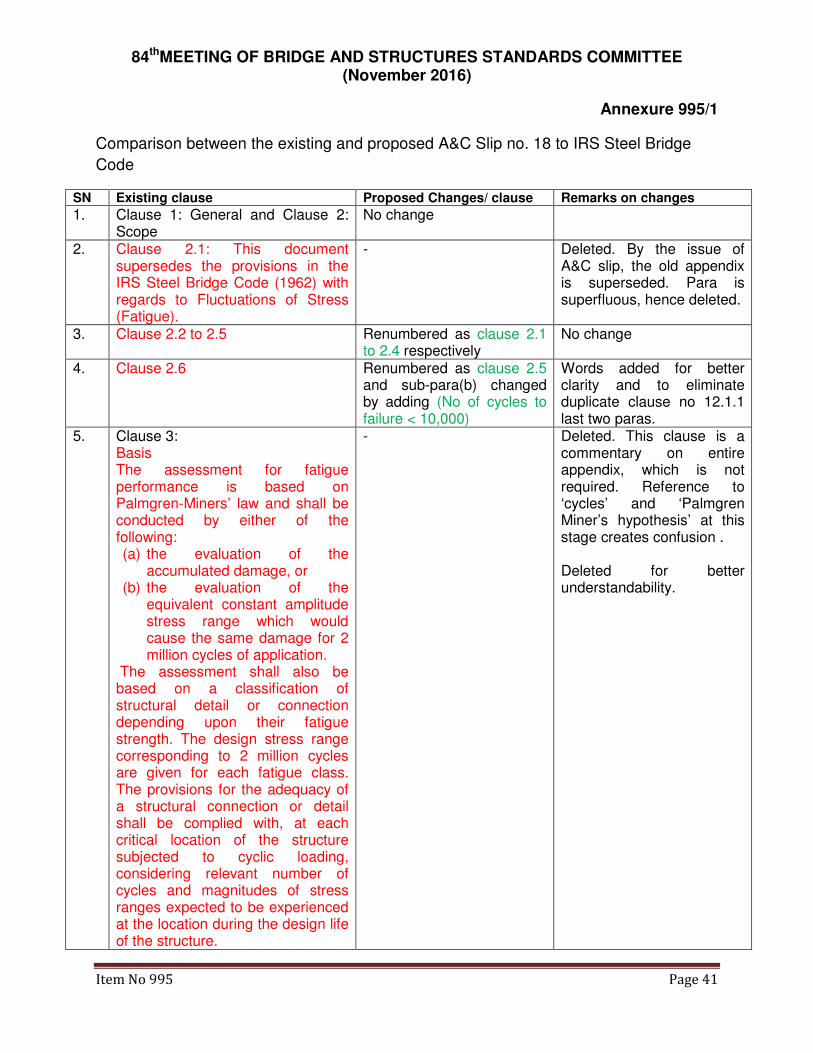
Annexure 995/1
Comparison between the existing and proposed A&C Slip no. 18 to IRS Steel Bridge
Code
SN Existing clause Proposed Changes/ clause Remarks on changes
1. Clause 1: General and Clause 2: Scope
No change
2. Clause 2.1: This document supersedes the provisions in the IRS Steel Bridge Code (1962) with regards to Fluctuations of Stress (Fatigue).
- Deleted. By the issue of A&C slip, the old appendix is superseded. Para is superfluous, hence deleted.
3. Clause 2.2 to 2.5 Renumbered as clause 2.1 to 2.4 respectively
No change
4. Clause 2.6 Renumbered as clause 2.5 and sub-para(b) changed by adding (No of cycles to failure < 10,000)
Words added for better clarity and to eliminate duplicate clause no 12.1.1 last two paras.
5. Clause 3: Basis The assessment for fatigue performance is based on Palmgren-Miners’ law and shall be conducted by either of the following: (a) the evaluation of the
accumulated damage, or (b) the evaluation of the
equivalent constant amplitude stress range which would cause the same damage for 2 million cycles of application.
The assessment shall also be based on a classification of structural detail or connection depending upon their fatigue strength. The design stress range corresponding to 2 million cycles are given for each fatigue class. The provisions for the adequacy of a structural connection or detail shall be complied with, at each critical location of the structure subjected to cyclic loading, considering relevant number of cycles and magnitudes of stress ranges expected to be experienced at the location during the design life of the structure.
- Deleted. This clause is a commentary on entire appendix, which is not required. Reference to ‘cycles’ and ‘Palmgren Miner’s hypothesis’ at this stage creates confusion . Deleted for better understandability.

84thMEETING OF BRIDGE AND STRUCTURES STANDARDS COMMITTEE (November 2016)
Item No 995 Page 42
6. Clause 4 Terms and Definition and 4.1 General
No change
7. Clause 4.1.1 to 4.1.5 No change in clauses 4.1.1, 4.1.2 and 4.1.5. Clause 4.1.3 renumbered as clause 4.1.4 and vice versa.
Sequence of terms changed such that latter concepts build on the previous concepts.
8. Clause 4.2 Loading and stress parameters Clause 4.2.1: Load/Loading event A defined sequence of loads passed over the structure. This shall usually consist of a sequence of axle loads, specified by the magnitude of the load and the interval between successive axles, or recommended equivalents to represent the passage of a train.
Clause 4.2 Loading and stress parameters Clause 4.2.1: Load/Loading event A defined sequence of loads (say, a train) which is passed over the structure a definite number of times during the life of a bridge. This shall usually consist of a sequence of axle loads, specified by the magnitude of the load and the interval between successive axles, or recommended equivalents to represent the passage of a train.
Slight modification done for better explaining the term “load”.
9. Clause 4.2.2 No change 10. Clause 4.2.3 Renumbered as clause
4.2.6 Sequence of terms changed such that latter concepts build on the previous concepts. Slight change in one heading.
11. Clause 4.2.4 Renumbered as clause 4.2.3
12. Clause 4.2.5 Renumbered as clause 4.2.4
13. Clause 4.2.6: Design Spectra Renumbered as clause 4.2.5: Design spectrum
14. Clause 4.2.7 Renumbered as clause 4.2.8
15. Clause 4.2.8 Renumbered as clause 4.2.9
16. Clause 4.2.9: Damage
Damage is the ratio of the actual number of cycles subjected to member detail/connection to the number of cycles to failure at a specific stress range.
Total damage is the linear combination of the ratios of the cycles of various stress ranges present to the number of cycles to failure, for each stress range in a stress spectrum, in accordance with the Palmgren – Miner’s cumulative
a) Renumbered as clause 4.2.10
b) Clause modified:
Damage: Damage is the ratio of the actual number of cycles a member detail/connection is subjected to and the number of cycles to failure at a specific stress range. This is computed for various stress ranges and added up
a) First line rearranged for correcting grammar. b) Reference to Palmgren-Miner’s rule removed as it has not yet been explained.
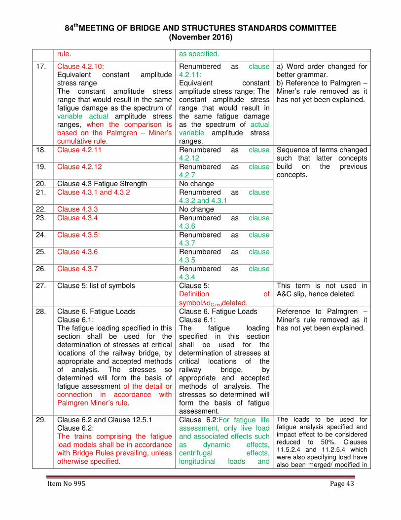
84thMEETING OF BRIDGE AND STRUCTURES STANDARDS COMMITTEE (November 2016)
Item No 995 Page 43
rule. as specified.
17. Clause 4.2.10: Equivalent constant amplitude stress range The constant amplitude stress range that would result in the same fatigue damage as the spectrum of variable actual amplitude stress ranges, when the comparison is based on the Palmgren – Miner’s cumulative rule.
Renumbered as clause 4.2.11: Equivalent constant amplitude stress range: The constant amplitude stress range that would result in the same fatigue damage as the spectrum of actual variable amplitude stress ranges.
a) Word order changed for better grammar. b) Reference to Palmgren – Miner’s rule removed as it has not yet been explained.
18. Clause 4.2.11 Renumbered as clause 4.2.12
Sequence of terms changed such that latter concepts build on the previous concepts.
19. Clause 4.2.12 Renumbered as clause 4.2.7
20. Clause 4.3 Fatigue Strength No change 21. Clause 4.3.1 and 4.3.2 Renumbered as clause
4.3.2 and 4.3.1 22. Clause 4.3.3 No change 23. Clause 4.3.4 Renumbered as clause
4.3.6 24. Clause 4.3.5: Renumbered as clause
4.3.7 25. Clause 4.3.6 Renumbered as clause
4.3.5 26. Clause 4.3.7 Renumbered as clause
4.3.4 27. Clause 5: list of symbols
Clause 5: Definition of
symbol∆σC,reddeleted.
This term is not used in A&C slip, hence deleted.
28. Clause 6. Fatigue Loads Clause 6.1: The fatigue loading specified in this section shall be used for the determination of stresses at critical locations of the railway bridge, by appropriate and accepted methods of analysis. The stresses so determined will form the basis of fatigue assessment of the detail or connection in accordance with Palmgren Miner’s rule.
Clause 6. Fatigue Loads Clause 6.1: The fatigue loading specified in this section shall be used for the determination of stresses at critical locations of the railway bridge, by appropriate and accepted methods of analysis. The stresses so determined will form the basis of fatigue assessment.
Reference to Palmgren – Miner’s rule removed as it has not yet been explained.
29. Clause 6.2 and Clause 12.5.1 Clause 6.2: The trains comprising the fatigue load models shall be in accordance with Bridge Rules prevailing, unless otherwise specified.
Clause 6.2:For fatigue life assessment, only live load and associated effects such as dynamic effects, centrifugal effects, longitudinal loads and
The loads to be used for fatigue analysis specified and impact effect to be considered reduced to 50%. Clauses 11.5.2.4 and 11.2.5.4 which were also specifying load have also been merged/ modified in

84thMEETING OF BRIDGE AND STRUCTURES STANDARDS COMMITTEE (November 2016)
Item No 995 Page 44
Clause 12.5.1: General The recommended equivalents for train loads shall be adopted in accordance with existing provisions of IRS Bridge Rules, including the
dynamic impact factor Φ, which is calculated as (1.0 + CDA), where CDA is the coefficient of Dynamic Augment as specified in IRS Bridge Rules.
racking loads only shall be considered subjected to the following:
6.2.1 For fatigue assessment, 50% of the impact loads specified in Bridge Rules shall be considered.
this clause. This is as discussed & decided in 82
nd BSC meeting for item
no. 995. Only live load + 50% Impact (Cl 8.7.1 of AS 5100:2) Impact taken 35% to 65% with values as 35% for “Beams, stringers, girders & floor beams”[Cl 1.3.13(d) of AREMA manual 2010, Vol. 2] 50% Impact [Cl D. 1(2) of EN 1991-2:2003] Only traffic load gives rise to fatigue [Cl. 4.6.1(1) & 4.6.1(2) Note 1 of EN 1991-2:2003]
30. Clause 6.3 The recommended traffic models for MBG standard to be adopted for the specification of the fatigue loads shall be in accordance with Table - 6.1
- Deleted.MBG/HM Loadings are no longer to be used for design. Hence these clauses are not required.
Clause 6.4 The recommended traffic models for HM routes to be adopted for the specification of the fatigue loads shall be in accordance with Table - 6.2
31. Clause 6.7: Other traffic models, in addition to the above or any modification thereof, may be considered as specified by the competent authority.
Clause 6.2.2: The fatigue assessment can be done for traffic forecast on a bridge based on actual loading history of trains passed over the bridge and/or future projection of traffic. The future traffic models to be used shall be as specified by Chief Bridge Engineer. Alternately, it can be done for standard train combinations. The following standard train combinations have been considered while formulating the simplified provisions for design as per this code:
This clause allows use of actual history and trains plying in section as this is required for fatigue assessment of existing bridges. The competent authority has been specified. Also, instead of mentioning the traffic models considered in A & C slip as “Recommended”, the same has been mentioned as “standard”.
32. Clause 6.5:The recommended traffic models for standard 25 t loading -2008 to be adopted for the specification of the fatigue loads shall be in accordance with Table - 6.3
Renumbered as Clause 6.2.2.1: The standard traffic models for 25 t loading -2008 to be adopted for fatigue assessment shall be in accordance with Table - 1, Appendix G-I.
Instead of “recommended”, word “standard” used to allow other traffic models to be used. Table nos changed and the same moved to Appendix G-I for better readability of the provisions. 33. Clause 6.6:The recommended Renumbered as clause

84thMEETING OF BRIDGE AND STRUCTURES STANDARDS COMMITTEE (November 2016)
Item No 995 Page 45
traffic models for standard 32.5 t loading (DFC Loading) to be adopted for the specification of the fatigue loads shall be in accordance with Table - 6.4
6.2.2.2: The standard traffic models for 32.5 t loading (DFC Loading) to be adopted for fatigue assessment shall be in accordance with Table - 2, Appendix G-I.
34. Clause 6.8: In case of bridges with multiple tracks, it is recommended that
Renumbered as clause 6.4: In case of bridges with multiple tracks, loading shall be done as follows
Reworded, as per normal codal language
35. Clauses 6.8 (a) to (c) Renumbered as clause 6.4 (a) to (c)
36. Clause 6.9: In general, the fatigue assessment, shall be conducted in accordance with 12.5 using either the actual train loads or their recommended equivalents in accordance with the Bridge Rules. The loaded length, for simplified analysis, is that length of the span which will give the maximum stress in the structural member or connection, when loaded by an equivalent uniformly distributed load.
- Deleted. This para which gave overview of further procedure was superfluous and was reducing readability, hence deleted.
37. Table 6.1/6.2 - Deleted as HM/MBG loadings are not to be used for design any more.
38. Tables 6.3/6.4 Renumbered as Tables G.I.1 and G.I.2
39. Clause 7: Determination of stresses
Renumbered as clause 11 Determination of stresses to be used for fatigue design: For each For each structural detail or joint being assessed for fatigue, typical load event (or train) produces a stress history plot, depending on position of the train at different time intervals. A typical stress history with time plot is shown in Figure A.1 of Appendix G-III. These stresses for different positions of train(s) shall be obtained for member(s) as follows:
The clause shifted to clause 11 so that the methodology of fatigue assessment is clear. In the existing A & C slip, these clauses are at different places, creating confusion.
40. - 11.1 Field Measurements: New clause added which

84thMEETING OF BRIDGE AND STRUCTURES STANDARDS COMMITTEE (November 2016)
Item No 995 Page 46
The stresses measured on members while actual trains/ test trains pass over the bridge and the plot of variation of stresses with position of train can be used for fatigue assessment of existing bridges. Based on these plots, stress history plots shall then be obtained for the other trains plying/ likely to ply on the bridge. For parameters difficult to replicate/ measure in field, such as impact, suitable modifications shall be made as per Bridge rules. This method captures the actual behaviour of girders. However, if the actual plot shape/ magnitude of stresses measured in field vary too much as compared with the theoretical expected stresses, reasons for the same shall be studied and designer shall decide if the measured stresses are reliable for fatigue assessment studies or not.
specifies methodology for actual field measurements. The earlier clause 7.1.1 was allowing only static linear elastic analysis. Field measurements are important for fatigue assessment of existing bridges.
41. Clause 7.1.1: The stresses due to the moving train loads shall be determined on the basis of static linear elastic analysis carried out in accordance with accepted principles and practices, unless otherwise stated or implied, taking into account all axial, bending and shear stresses occurring under the prescribed fatigue loading. No redistribution of loads or stresses is permitted from any consideration whatsoever. Clause 7.1.3:(First Line) The nominal stresses should be calculated at the location of potential fatigue initiation.
Renumbered as clause 11.2:Theoretical Computations: Alternately, the theoretical plot of stress with position of actual/expectedmoving train loads shall be worked out for the fatigue loads specified in clause 6 above. Stresses shall be determined on the basis of static linear elastic analysis carried out in accordance with accepted principles and practices, unless otherwise stated or implied, taking into account all axial, bending and shear stresses occurring under the
Para reworded and split for better readability. It has been added that the stresses due to fatigue loads only is to be considered as mentioned in clause 6. The last line of the existing clause 7.1.1 “No redistribution of loads or stresses is permitted from any consideration whatsoever” has been mentioned in proposed clause 11.3.1.

84thMEETING OF BRIDGE AND STRUCTURES STANDARDS COMMITTEE (November 2016)
Item No 995 Page 47
prescribed fatigue loading. Clause 11.4 Modification in measured/computed stresses Clause 11.4.1: The nominal stresses should be calculated at the location of potential fatigue initiation. No redistribution of loads or stresses is permitted from any consideration whatsoever.
New clause introduced by adding first line from clause 7.1.3 and the second line from clause 7.1.1. This makes it easier to understand the provisions.
42. Clause 7.1.2:(First Part) Where applicable the effect of the following should be incorporated in the stress calculations :- (a) Shear lag, restrained torsion and distortion, transverse stresses and flange curvature (b) Effective width of steel plates (c) Load application away from joints, member eccentricities at joints and rigidity of joints in triangulated skeletal structures.
Renumbered as clause 11.4.2: Where applicable, effect of the following should be incorporated in the stress calculations:- (a) Shear lag, restrained torsion and distortion, transverse stresses and flange curvature (b) Effective width of steel plates (c) Load application away from joints, member eccentricities at joints and rigidity of joints in triangulated skeletal structures. (d) Stress concentration effects, when specifically stated as a requirement for a detail or joint, which shall be accounted for by using an appropriate stress concentration factor.
The clause 7.1.2 had two parts. The same is split up as clause 11.4.2 and 11.4.3 for easier referencing. New clause 11.4.2(d) comes from 7.1.2 second part (c) to avoid the double negative earlier used which makes it difficult to understand the provisions. Part of 7.1.3 included here for making the meaning clear.
43. Clause 7.1.2:(Second Part)The effects of the following, however, need not be included in the stress calculations (a) Residual stresses (b) Eccentricities arising in a standard detail (c) Stress concentration, except when specifically stated as a requirement for a detail or joint. Clause 7.1.3:(Second Line) Stress concentration at details, other than those covered in Tables 9.1 to 9.6 shall be accounted for by
Renumbered as clause 11.4.3: The effects of the following need not be included in the stress calculations (a) Residual stresses. (b) Eccentricities arising in a standard detail. (c) The standard stress concentration associated with a detail as given in tables G-II.1 to G-II.6 which has already been considered in the fatigue
Clause 7.1.2 second part joined with second line of 7.1.3 for better clarity. 11.4.3 (c) wording removes the existing double negative in 7.1.2 (c)
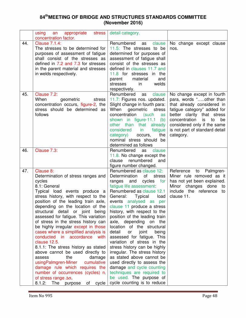
84thMEETING OF BRIDGE AND STRUCTURES STANDARDS COMMITTEE (November 2016)
Item No 995 Page 48
using an appropriate stress concentration factor.
detail category.
44. Clause 7.1.4: The stresses to be determined for purposes of assessment of fatigue shall consist of the stresses as defined in 7.2 and 7.3 for stresses in the parent material and stresses in welds respectively.
Renumbered as clause 11.5: The stresses to be determined for purposes of assessment of fatigue shall consist of the stresses as defined in clauses 11.7 and 11.8 for stresses in the parent material and stresses in welds respectively.
No change except clause nos.
45. Clause 7.2: When geometric stress concentration occurs, figure-2, the stress should be determined as follows
Renumbered as clause 11.7: Figures nos. updated. Slight change in fourth para: When geometric stress concentration (such as shown in figure-11.1 (b) other than that already considered in fatigue category) occurs, the nominal stress should be determined as follows
No change except in fourth para, words “…..other than that already considered in fatigue category” added for better clarity that stress concentration is to be considered only if the same is not part of standard detail category.
46. Clause 7.3: Renumbered as clause 11.8. No change except the clause renumbered and figure number changed.
47. Clause 8: Determination of stress ranges and cycles 8.1: General Typical load events produce a stress history, with respect to the position of the leading train axle, depending on the location of the structural detail or joint being assessed for fatigue. This variation of stress in the stress history can be highly irregular except in those cases where a simplified analysis is conducted in accordance with clause 12.5. 8.1.1: The stress history as stated above cannot be used directly to assess the damage usingPalmgren-Miner cumulative damage rule which requires the number of occurrences (cycles) ni
of stress range ∆σi. 8.1.2: The purpose of cycle
Renumbered as clause 12: Determination of stress ranges and cycles for fatigue life assessment: Renumbered as clause 12.1 General: Typical load events analysed as per clause 11 produce a stress history, with respect to the position of the leading train axle, depending on the location of the structural detail or joint being assessed for fatigue. This variation of stress in the stress history can be highly irregular. The stress history as stated above cannot be used directly to assess the damage and cycle counting techniques are required to be used. The purpose of cycle counting is to reduce
Reference to Palmgren-Miner rule removed as it has not yet been explained. Minor changes done to include the reference to clause 11.

84thMEETING OF BRIDGE AND STRUCTURES STANDARDS COMMITTEE (November 2016)
Item No 995 Page 49
counting is to reduce a complex stress history to a sequence of stress ranges and the corresponding number of cycles of occurrence in the stress history.
a complex stress history to a sequence of stress ranges and the corresponding number of cycles of occurrence in the stress history.
48. Clause 8.2:
Renumbered as clause 12.2:
No change.
49. Clause 8.2.1: Determination of stress ranges and cycles by the reservoir method This method of cycle counting is most suited to stress histories consisting of a few peaks and troughs as produced by simplified analysis using recommended equivalent loads. The method consists of imagining the stress history as the section of a reservoir which is drained successively from each of the lowest points till the reservoir is empty. Each draining operation is considered to be equivalent to one cycle of a stress range equal in magnitude to the maximum height of water drained in that particular operation (see Appendix G-A).
Renumbered as clause 12.2.1: Determination of stress ranges and cycles by the reservoir method: The method consists of imagining the stress history as the section of a reservoir which is drained successively from each of the lowest points till the reservoir is empty. Each draining operation is considered to be equivalent to one cycle of a stress range equal in magnitude to the maximum height of water drained in that particular operation (see Appendix G-III)
First line deleted as same is confusing. Technical content of this line already covered in appendix-III.
50. Clause 8.2.2: Determination of stress ranges and cycles by the rainflow method The rainflow method as the name suggests counts half cycles based on the visualization of the complex stress history as a sequence of pagoda roofs over which rain tickles down. In order to achieve the above the stress history is rotated by 90o (see Appendix G-A). The rules for counting half cycles are as follows:- - A drop begins to flow left from the upper side of a peak or right from the lower side of a trough onto subsequent roofs unless the surface receiving the drop is formed by a peak which is more positive than the origin of the drop for a left flow, or, a trough that is more negative for a right flow.
Renumbered as clause 12.2.2: Determination of stress ranges and cycles by the rainflow method: The rainflow method as the name suggests counts half cycles based on the visualization of the complex stress history as a sequence of pagoda roofs over which rain tickles down. In order to achieve the above the stress history is rotated by 900 (see Appendix G-III). Counting of cycles shall be done as per rules given in Appendix G-III
Rules of method removed from this clause as these are already given in appendix G-III.

84thMEETING OF BRIDGE AND STRUCTURES STANDARDS COMMITTEE (November 2016)
Item No 995 Page 50
-The path of a drop cannot cross the path of a drop which has fallen from a higher roof. -The horizontal displacement of the drop from its origin to its final position measured in appropriate stress units represents a half cycle of the associated stress range.
51. Clause 8.3 Modification of stress ranges 8.3.1 General The fatigue assessment should be carried out using (a) Nominal stress ranges for
details shown in tables 9.1 to 9.5
(b) Modified nominal stress ranges where abrupt changes of section occur close to the initiation of potential crack locations (for details not covered in tables 9.1 to 9.5)
(c) Geometric stress ranges where high stress gradients occur close to a weld in toe joints covered in table 9.6
The design values of stress range to be used for the fatigue assessment should be the stress
range γFf*∆σE,2corresponding to NC = 2 x 10⁶ cycles.
Renumbered as clause 11.6 Modification of stress ranges based on geometric stress range: 11.6.1 Where abrupt changes of section occur close to the potential crack locations (for details not covered in tables G.II.1 to G.II.5), high stress gradients occur close to a weld in toe joints (covered in Table G-II.6), geometric stress range shall be used.
Both clauses, 8.3.1 and 12.4 merged and moved to clause 11.6 for logical flow of ideas and to avoid duplication as earlier. The stress range to be used is already covered in old clause 12.4.5, which has been merged with 11.6.1. As given below, clauses 12.4.1 to 12.4.4 renumbered as 11.6.2 to 11.6.5.
52. Clause 8.3.2 to clause 8.3.4 - Deleted as these clauses are giving theory of fatigue design. The λ values to be
used ought to be clearly specified in the code. These clauses were creating confusion with the designers, hence deleted.
53. Clause 9, 9.1 and 9.2 Tables 9.1 to 9.6
No change except table nos changed to Tables G.II.1 to G.II.6.
Tables shifted to Appendix G-II for better readability of the A & C slip.
Table 9.1 Table G.II.1 Fatigue categories 7(a) and 7(b) added. Fatigue category 100.
These categories are required for fatigue design of shear stresses. Fatigue category same as in table 8.1 of EN:1993-1-9, details 6 and 7.
54. Clause 10: S-N Curves
Clause 10: Determination of fatigue
No change except heading which has been changed to

84thMEETING OF BRIDGE AND STRUCTURES STANDARDS COMMITTEE (November 2016)
Item No 995 Page 51
strength reflect the actual purpose of this clause in the design process.
55. Clause 10.1:
No change except figure no. changed
Fig. 3 has been renumbered as fig. 10.1.
56. Clause 10.1.1
10.2. Parameters of S-N curves Renumbered as clause 10.2.1
57. Clause 10.1.2 Renumbered as clause 10.2.2
58. Clause 10.2:Specification of S-N curves The fatigue strength curves for constant amplitude nominal stresses are as shown in figures 4 and 5 and are defined as :-
NR *(∆σR)m = 2 * 106 * (∆σC)m
with m=3 for N ≤ 5*106
NR *(∆τR)m = 2 * 106 * (∆τC)m
with m=5 for N ≤ 108
where CCD σσσ ∆=∆
=∆ 7368.0*5
2 31
is the
constant amplitude fatigue limit
and CCL τττ ∆=∆
=∆ 4573.0*100
2 51
is
the cut off limit at 100 million cycles. 10.2.1: The fatigue strength curves for nominal stress spectra above and below the constant amplitude
fatigue limit ∆σD are defined as :-
NR * (∆σR)m = 2 * 106 * (∆σC)m
with m=3 for N ≤ 5*106
NR * (∆σR)m = 5 * 106 * (∆σD)m
with m=5 for 5*106≤ N≤108
where DDL σσσ ∆=∆
=∆ *5493.0*100
5 51
is
the cut off limit at 100 million cycles
Rewritten in clause 10.2.3 and 10.2.4 10.2.3: S-N curve for constant amplitude normal stress ranges: These curves for different fatigue categories are shown in figure 10.1. Each curve is described as below: 10.2.3.1: From 104 cycles to 5 x 10⁶ cycles, the curve has a negative slope of 3.
The value of ∆σD at 5 x 10⁶ cycles is called constant amplitude fatigue limit. The fatigue strength in this part is defined by:
NR *(∆σR)m= 2 * 106 * (∆σC)m,
with m=3 for NR≤ 5*106
Where
CCD σσσ ∆=∆
=∆ 7368.0*5
2 31 and
NR is the number of cycles to failure corresponding to
∆σR read from the appropriate S-N curve. 10.2.3.2 From 5 x 10⁶ cycles to 1 x 10⁸ cycles, the curve has a negative slope
Fig. 4 and 5 has been renumbered as fig 10.2 and 10.3 respectively. Clause separated into two separate clauses to explain the two different curves and also divided into sub-clauses to explain the curves properly. Appendix G-B has been deleted as it was a commentary on how the values in curves have been worked out.

84thMEETING OF BRIDGE AND STRUCTURES STANDARDS COMMITTEE (November 2016)
Item No 995 Page 52
Clause 10.2.3 Fatigue strength curves for nominal normal stresses for typical detail categories are as given in figure 4. The characteristic fatigue strength for each category is specified by the stress range corresponding to failure at 2 million cycles. The limiting stress range is the magnitude of the stress range corresponding to 10000 cycles to failure while the constant amplitude fatigue limit and the cut off limit are the fatigue strengths corresponding to 5 million and 100 million cycles to failure respectively. The curve has a constant slope m = 3 from the limiting stress range to the constant amplitude fatigue limit. The fatigue strength curve is bilinear with a constant slope m = 5 from the constant amplitude fatigue limit to the cut off limit. The numerical values for calculating the fatigue strength are as given in Table 10.1(Also see Table 10.1A in Appendix G-B).
of 5. The value of ∆σL at 100 million cycles is called cut off limit. The fatigue strength in this part is defined by:
NR * (∆σR)m = 5 * 106 *
(∆σD)m
with m=5 for 5*106< NR≤108
where
DDL σσσ ∆=∆
=∆ *5493.0*100
5 51
10.2.3.3 Beyond 1 x 10⁸ cycles, the curve has NIL slope and there is no fatigue damage. 10.2.4 S-N curve for constant amplitude shear stress ranges: These curves for different fatigue categories are shown in figure 10.3. Each curve is described as below: 10.2.4.1 From 104 cycles to 1 x 10⁸ cycles, the curve has a negative slope of 5.
The value of ∆τL is the cut off limit at 100 million cycles. The fatigue strength curves for shear stress are defined as:
NR *(∆τR)m = 2 * 106 *
(∆τC)m,
with m=5 for NR≤ 108
where
CCL τττ ∆=∆
=∆ 4573.0*100
2 51
is the cut off limit at 100 million cycles 10.2.4.2 Beyond 1 x 10⁸ cycles, the curve has NIL slope and there is no fatigue damage.
Clause 10.2.4 The fatigue strength curves for nominal shear stress ranges are as given in figure 5. The characteristic fatigue strength for each category is specified by the stress range corresponding to failure at 2 million cycles. The limiting stress range is the magnitude of the stress range corresponding to 10000 cycles to failure while there is no constant amplitude fatigue limit the cut off limit is the fatigue strength corresponding to 100 million cycles to failure as in the case of nominal normal stresses. The curve has a single constant slope m = 5 from the limiting stress range to the cut off limit. The numerical values for calculating the fatigue strength are as given in Table 10.2(Also see Table 10.2A in Appendix G-B).
59. Clause 10.2.2: The fatigue strength curves for
Renumbered as clause 10.2.5:
Equation for ∆τR added to cover shear stress also.

84thMEETING OF BRIDGE AND STRUCTURES STANDARDS COMMITTEE (November 2016)
Item No 995 Page 53
nominal normal stresses are also defined by
log N = log a – m * log ∆σR where
∆σR is the fatigue strength N is the number of cycles to
failure of stress range ∆σR m is the constant slope of the fatigue strength curves log a is a constant which depends on the specific segment of the fatigue curve The numerical values for the fatigue strength curves for normal and shear stress ranges are as given in Tables 10.1 and 10.2 respectively.
Equations defining S-N curves: The fatigue strength curves for nominal normal/shear stresses are also defined by log NR = log a – m * log
∆σR or log NR = log a – m *
log ∆τR
where ∆σRor ∆τR is the fatigue strength
NR is the number of cycles to failure of stress
range ∆σR or ∆τR m is the constant slope of the fatigue strength curves log a is a constant which depends on the specific segment of the fatigue curve. The numerical values for the fatigue strength curves for normal and shear stress ranges as defined by above are given in Tables 10.1 and 10.2 respectively.
The earlier term N was wrong as per definitions of the terms given in clause 2, hence corrected to NR. Word ‘corresponding’ added for better clarity separately.
60. Clause 10.2.5 The above fatigue strength curves will not be applicable for stress ranges which are associated with less than 10000 cycles to failure.
- Deleted as it is already covered in exceptions in clause 2.
61. Clause 10.3, Clause 10.3.1, Clause 10.3.2 and 10.3.2.1
Clause 10.3, Clause 10.3.1, Clause 10.3.2 and 10.3.2.1: No change except figure no. Headings added to 10.3.1 and 10.3.2
The wording “figure 6” has been replaced by “Figure 10.3”
62. Clause 10.3.2.2: The variation of fatigue strength with thickness, of the parent metal, greater than 25 mm shall be accounted for by reducing the fatigue strength as :-
20.0
, )/25(* tRtR σσ ∆=∆
Clause 10.3.2.3: Where the material thickness of the structural detail is less than 25 mm the fatigue strength shall be taken as that for a thickness of 25 mm
RtR σσ ∆=∆ ,
Merged and renumbered as clause 10.3.2.2: Where the material thickness of the structural detail is greater than 25 mm, the effect of thickness shall be accounted for by reducing the fatigue strength as :-
20.0
, )/25(* tRtR σσ ∆=∆ ,
where 25/t ≤1
Slight rewording done by merging old 10.3.2.2 and 10.3.2.3.

84thMEETING OF BRIDGE AND STRUCTURES STANDARDS COMMITTEE (November 2016)
Item No 995 Page 54
63. Clause 10.3.2.4:
Renumbered as clause 10.3.2.3
64. Clause 10.3.3 Table and figure nos. changed.
65. Clause 10.3.3.1, Figure 7 and Appendix G-B
- Deleted. 10.3.3.1 and Fig 7 described the way in which the values in Appendix B have been worked out. This was a commentary on code as to how the curves have been derived. Deleted as not required in the code.
66. Clause 11 Renumbered as clause 7 Sequence changed as the partial safety factors shall be decided before the design is taken up in hand.
67. Clause 11.1:General The values of the partial safety factors to be used shall be as specified herein unless otherwise recommended by the appropriate competent authority, taking into due consideration: (a) the ease of access for inspection or repair and likely frequency of inspection and maintenance, (b) the consequences of failure.
Renumbered as clause 7.1 General: The values of the partial safety factors to be used shall be as specified herein unless otherwise recommended by the Railway Board, taking into due consideration: (a) the ease of access for inspection or repair and likely frequency of inspection and maintenance, (b) the consequences of failure
Competent authority defined.
68. Clause 11.2 and 11.2.1 Merged and renumbered as clause 7.2
No change
69. Clause 11.3 and 11.3.1 Merged and renumbered as clause 7.3
No change
70. Clause 11.4 Renumbered as clause 7.4 No change
71. Clause 12: Fatigue assessment procedures
Renumbered as clause 3: Limitations of provisions in this Appendix
Renumbered for proper order of terms/concepts. The limitations of the provisions shall come before the provisions are enumerated.
72. Clause 12.1.1(First part): Limitations - For fatigue assessment, all nominal stresses, direct or shear, shall be within the elastic limits of the material. The range of the design values of such stresses shall not exceed 1.5 fy for normal
Renumbered as clause 3.1 & 3.2: 3.1 For fatigue assessment, all nominal stresses, direct or shear, shall be within the elastic limits of the material. The range of the design values of such stresses
Paragraphs numbered for easy referencing

84thMEETING OF BRIDGE AND STRUCTURES STANDARDS COMMITTEE (November 2016)
Item No 995 Page 55
stresses or 1.5 fy/√3 for shear stresses. - The fatigue strengths specified in this document are applicable to structures where suitable corrosion protection measures have been undertaken and corrosion is not allowed to take place.
shall not exceed 1.5 fy for
normal stresses or 1.5 fy/√3 for shear stresses. 3.2 The fatigue strengths specified in this document are applicable to structures where suitable corrosion protection measures have been undertaken and corrosion is not allowed to take place.
73. Clause 12.1.1(Second part): - The fatigue assessment procedures herein are applicable only to structures subjected to temperatures not exceeding 150 °C. - The constant amplitude stress range or a component of the variable amplitude stress ranges, under the prescribed fatigue loading, for a structural connection or detail is such that either the nominal stress range exceeds the limiting stress or the endurance is equal to or less than 10,000 cycles.
- Deleted as these are already included in clause 2.5.
74. Clause 12.1.2: Exceptions: No fatigue assessment is required when any of the following conditions is satisfied;
Renumbered as clause 8.1: No fatigue assessment: Fatigue assessment is not required in the following cases:
Clause no. 8 in re-revised appendix gives method for carrying out assessment. This clause has shifted there to ensure all relevant clauses are at one place.
75. Clause 12.1.2.1 to Clause 12.1.2.3 Renumbered as clause 8.1.1 to clause 8.1.3
76. - Clause 8.2 Classification of details: All details which are to be designed under fatigue shall first be classified so that standard curves known as S-N curves (explained in clause 10)shall be used wherever possible. The details shall be classified as per clause 9. Clause 8.3 Determination of fatigue strength: Corresponding to the detail classification, the fatigue strength shall be worked out
New clauses added to explain the step by step procedure in fatigue evaluation/design.

84thMEETING OF BRIDGE AND STRUCTURES STANDARDS COMMITTEE (November 2016)
Item No 995 Page 56
as per clause 10. Clause 8.4 Determination of stress history: For each detail to be studied under fatigue, stress histories to be used for fatigue study have to be determined. If actual field measurements or detailed analytical analysis of stresses is being done, clauses 11 and 12 shall be followed. For new construction, especially where the accurate traffic details are not available, simplified method given in clause 14 may be followed. Clause 8.5 Fatigue Assessment: The fatigue assessment of each detail shall be done as per clause 13. Clause 8.6: Simplified fatigue analysis may be done as per clause 14 if actual field measurements or detailed analytical analysis of stresses are not done.
77. Clause 12.2: General
Renumbered as clause 13: Fatigue assessment:-Fatigue assessment refers either to checking if a member has been designed with adequate fatigue life or to verifying if the residual fatigue life of a member is adequate. Stresses determined/ modified in accordance with clause 12 shall be used for this purpose.
78. Clause 12.2.1 Renumbered as clause 13.1 79. Clause 12.2.2 to 12.2.4 Renumbered as clauses
11.3.1 to 11.3.3 Table nos changed.
80. Clause 12.2.5 and clause 12.2.6 - Deleted. These sub-clauses arealready included in existing clauses 7.2.2 and 7.2.3.
81. Clause 12.3 Fatigue assessment Renumbered as clause Shear stress also added for
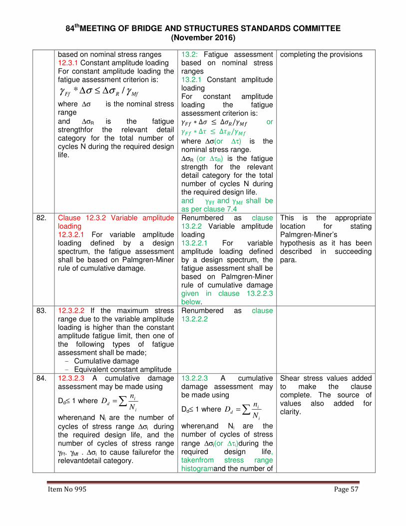
84thMEETING OF BRIDGE AND STRUCTURES STANDARDS COMMITTEE (November 2016)
Item No 995 Page 57
based on nominal stress ranges 12.3.1 Constant amplitude loading For constant amplitude loading the fatigue assessment criterion is:
MfRFf γσσγ /* ∆≤∆
where ∆σ is the nominal stress range
and ∆σR is the fatigue strengthfor the relevant detail category for the total number of cycles N during the required design life.
13.2: Fatigue assessment based on nominal stress ranges 13.2.1 Constant amplitude loading For constant amplitude loading the fatigue assessment criterion is: ��� ∗ ∆� ≤ ∆�/��� or
��� ∗ ∆� ≤ ∆�/���
where ∆σ(or ∆τ) is the nominal stress range.
∆σR (or ∆τR) is the fatigue strength for the relevant detail category for the total number of cycles N during the required design life. and γ�� and γ�� shall be as per clause 7.4
completing the provisions
82. Clause 12.3.2 Variable amplitude loading 12.3.2.1 For variable amplitude loading defined by a design spectrum, the fatigue assessment shall be based on Palmgren-Miner rule of cumulative damage.
Renumbered as clause 13.2.2 Variable amplitude loading 13.2.2.1 For variable amplitude loading defined by a design spectrum, the fatigue assessment shall be based on Palmgren-Miner rule of cumulative damage given in clause 13.2.2.3 below.
This is the appropriate location for stating Palmgren-Miner’s hypothesis as it has been described in succeeding para.
83. 12.3.2.2 If the maximum stress range due to the variable amplitude loading is higher than the constant amplitude fatigue limit, then one of the following types of fatigue assessment shall be made; - Cumulative damage - Equivalent constant amplitude
Renumbered as clause 13.2.2.2
84. 12.3.2.3 A cumulative damage assessment may be made using
Dd≤ 1 where ∑=i
i
dN
nD
whereniand Ni are the number of
cycles of stress range ∆σi during the required design life, and the number of cycles of stress range
γFf. γMf . ∆σi to cause failurefor the relevantdetail category.
13.2.2.3 A cumulative damage assessment may be made using
Dd≤ 1 where ∑=i
i
dN
nD
whereniand Ni are the number of cycles of stress
range ∆σi(or ∆τi)during the required design life, takenfrom stress range histogramand the number of
Shear stress values added to make the clause complete. The source of values also added for clarity.

84thMEETING OF BRIDGE AND STRUCTURES STANDARDS COMMITTEE (November 2016)
Item No 995 Page 58
cycles of stress range γFf .
γMf .∆σi(or γFf*γMf*∆τi) to cause failurefor the relevantdetail category, read from the appropriate S-N curve given in clause 10.
85. Clause 12.3.2.4, 12.3.2.7, 12.3.2.8 and 12.3/12.3.3.1
- Deleted. These clauses allowed use of either a single slope curve or a double slope curve or a triple slope curve. The single/ double slope curves are slightly conservative but the computations are easier with these. Given that work can be done with computers/ calculators, the ease of computations is not really required, hence the clauses deleted.
86. Clause 12.3.2.6 Renumbered as clause 13.2.5and formula for shear included.
87. Clause 12.3.2.9 Renumbered as clause 13.2.6and formula for shear included.
88. Clause 12.3.2.5 and 12.3.3.2 Renumbered as 13.2.3 and 13.2.4
The Ni computations shifted to the location where these are to be used, for proper sequencing
89. Clause 12.3.4 Renumbered as clause 13.3 90. Clause 12.3.4.1 to 12.3.4.7 Renumbered as clause
13.3.1 to 13.3.7
91. Clause 12.4 Fatigue Assessment based on geometric stress ranges Clause 12.4.1 to 12.4.4
Renumbered asClause 11.6Fatigue Assessment based on geometric stress ranges Renumbered as clause 11.6.2 to 11.6.5. Only clause number changed as per new numbers.
Merged with clause 8.3.1 and incorporated as clause 11.6.
92. Clause 12.4.5 - Deleted. This is included in clause 11.6.1.
93. Clause 12.5.1 - Deleted. Loads for fatigue assessment already included in new clause 6.2
94. Clause 12.5/12.5.2.1: Assessment for simplified load models: For the simplified fatigue loading
Renumbered as clause 14: Simplified Approach if actual field measurements
There shall be no need for taking permission from any authority for using simplified
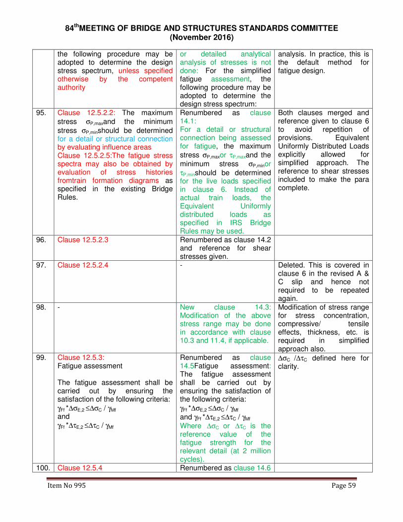
84thMEETING OF BRIDGE AND STRUCTURES STANDARDS COMMITTEE (November 2016)
Item No 995 Page 59
the following procedure may be adopted to determine the design stress spectrum, unless specified otherwise by the competent authority
or detailed analytical analysis of stresses is not done: For the simplified fatigue assessment, the following procedure may be adopted to determine the design stress spectrum:
analysis. In practice, this is the default method for fatigue design.
95. Clause 12.5.2.2: The maximum
stress σP,maxand the minimum
stress σP,minshould be determined for a detail or structural connection by evaluating influence areas Clause 12.5.2.5:The fatigue stress spectra may also be obtained by evaluation of stress histories fromtrain formation diagrams as specified in the existing Bridge Rules.
Renumbered as clause 14.1: For a detail or structural connection being assessed for fatigue, the maximum
stress σP,maxor τP,maxand the
minimum stress σP,minor
τP,minshould be determined for the live loads specified in clause 6. Instead of actual train loads, the Equivalent Uniformly distributed loads as specified in IRS Bridge Rules may be used.
Both clauses merged and reference given to clause 6 to avoid repetition of provisions. Equivalent Uniformly Distributed Loads explicitly allowed for simplified approach. The reference to shear stresses included to make the para complete.
96. Clause 12.5.2.3 Renumbered as clause 14.2 and reference for shear stresses given.
97. Clause 12.5.2.4 - Deleted. This is covered in clause 6 in the revised A & C slip and hence not required to be repeated again.
98. - New clause 14.3: Modification of the above stress range may be done in accordance with clause 10.3 and 11.4, if applicable.
Modification of stress range for stress concentration, compressive/ tensile effects, thickness, etc. is required in simplified approach also.
99. Clause 12.5.3: Fatigue assessment
The fatigue assessment shall be carried out by ensuring the satisfaction of the following criteria:
γFf *∆σE,2 ≤∆σC / γMf and
γFf *∆τE,2 ≤∆τC / γMf
Renumbered as clause 14.5Fatigue assessment: The fatigue assessment shall be carried out by ensuring the satisfaction of the following criteria:
γFf *∆σE,2 ≤∆σC / γMf
and γFf *∆τE,2 ≤∆τC / γMf
Where ∆σC or ∆τC is the reference value of the fatigue strength for the relevant detail (at 2 million cycles).
∆σC /∆τC defined here for clarity.
100. Clause 12.5.4 Renumbered as clause 14.6

84thMEETING OF BRIDGE AND STRUCTURES STANDARDS COMMITTEE (November 2016)
Item No 995 Page 60
101. Clause 12.5.4.1 & 12.5.4.7 Renumbered as clause 14.6.1
The value of λmax from
clause 12.5.4.7 incorporated here itself for easier reading.
102. Clause 12.5.4.2
The value of λ1 may be obtained from tables 7.1 to 7.4 for MBG loading, HM loading, 25t loading – 2008 and 32.5t loading (DFC)respectively as a function of the loaded length (see 6.9) for the train types included in respective traffic models. The loaded length shall depend upon the influence line diagram of the structural element or detail/connection under consideration. For simplified analysis the maxima for each length category could be adopted. For routes with train types other than those considered above, the competent authority may specify
alternative values of λ1.
Renumbered as clause 14.6.2:
The value of λ1 may be obtained from tables 14.6.2 (1) and 14.6.2 (2)for 25t loading – 2008 and 32.5t loading (DFC) respectively as a function of the loaded length for the train types included in respective traffic models. The loaded length shall depend upon the influence line diagram of the structural element or detail/connection under consideration. For simplified analysis the maxima for each length category could be adopted. For routes with train types other than those considered above, the designer may use
alternative values of λ1.
Table nos changed and reference to MBG and HM loadings removed as these are not to be used for design any more. Reference to old clause 6.9 not required as the sequence of clauses has been rectified. The designer given authority to use alternative
values of λ1 if other train types are there.
103. Clause 12.5.4.3 to 12.5.4.4 Renumbered as clause 14.6.3 and 14.6.4
Only figure number changed.
104. Clause 12.5.4.5: Unless otherwise specified by the
competent authority the value of λ3
will be taken as 1.00 for a design life of 100 years. For other values of design life the corresponding value may be calculated from the following expression where LD is the design life in years
2048.0
3 *3899.0 DL=λ
Renumbered as clause 14.6.5:
The value of λ3, in terms of the design life may be calculated from the following expression where LD is the design life in years:-
2048.0
3 *3899.0 DL=λ
For 100 years life, the value
of λ3 comes to 1.00 only. In view of flexibility in design life being given in clause 3.6.5 of Steel Bridge Code, the clause is reworded. The earlier clause was contradictory in this sense.
105. Clause 12.5.4.6 Renumbered as clause 14.6.6
106. Clause 12.5.4.7 Combined with 14.6.1 107. Appendix G-A Renumbered as Appendix
G.III No change.
108. Clause 3.6.4 of Steel Bridge Code-For any structural member or connection, the fatigue assessment shall be made as per Appendix ‘G’ (revised) for a specified ‘Design
Clause 3.6.4 of Steel Bridge Code - For any structural member or connection, the fatigue assessment shall be made as per Appendix
The loads to be used for fatigue assessment have been specified in Appendix ‘G’ (re-revised), hence reference to Bridge Rules

84thMEETING OF BRIDGE AND STRUCTURES STANDARDS COMMITTEE (November 2016)
Item No 995 Page 61
Life’ and ‘Fatigue Load Model’. The trains comprising the fatigue load models shall be in accordance with Bridge Rules.
‘G’(re-revised)for a specified ‘Design Life’ and ‘Fatigue Load Model’.
removed.
109. Clause 3.6.4 of Steel Bridge Code-The fatigue assessment shall be made for a standard design life of 100 years for a standard GMT of 50. Note:- No allowance for fatigue need be made in the design of Foot Over Bridges.
Clause 3.6.4 of Steel Bridge Code - The fatigue assessment shall be made for a standard design life of 100 years for a standard GMT of 50. However, any other design life/annual GMT may be used for design with the approval of Chief Bridge Engineer. Note:- No allowance for fatigue need be made in the design of Foot Over Bridges.
The standard design life and GMT are creating problems in sections like DFC where much higher GMT is anticipated, hence freedom to change the standard values incorporated.
110. - Add a new clause 3.20.4 of Steel Bridge Code - Fatigue assessment for Existing Bridges- The procedure given in appendix ‘G’ (Re-Revised) shall be followed for carrying out fatigue assessment of members of existing bridges, using either actual field measurements or numerical models validated with field measurements. Traffic and repair history of the bridge shall be used as accurately as possible. In the absence of accurate data, conservative estimates shall be made.
The correction slip has been expanded to include the fatigue assessment of existing bridges, hence this clause proposed to be introduced. The use of actual field measurements or numerical models validated with field measurements shall help in correct assessment of residual fatigue assessment of existing steel bridges.
************

Item No 995 Page G.1
Annexure 995/2
GOVERNMENT OF INDIA
MINISTRY OF RAILWAYS
(RAILWAY BOARD)
INDIAN RAILWAY STANDARD
CODE OF PRACTICE FOR THE DESIGN OF
STEEL OR WROUGHT IRON BRIDGES
(STEEL BRIDGE CODE)
Adopted – 1944
Revised – 1962
Reprinted in 1977
(Incorporating Correction Slips 1 to 10)
Addendum & Correction Slip No. ….dated ……….. (Draft)
1.0 Delete existing Clause 3.6.4/ Clause 3.6.5 and insert revised clauses as under:
Clause 3.6.4 – For any structural member or connection, the fatigue design shall be done as
per Appendix ‘G’ (Re-Revised) for a specified ‘Design Life’ and ‘Fatigue Load Model’.
Clause 3.6.5 –The fatigue life assessment shall normally be made for a standard design life
of 100 years for a standard annual GMT of 50. However, any other design life/ annual GMT
may be used for design with the approval of Chief Bridge Engineer.
Note:- No allowance for fatigue need be made in the design of Foot Over Bridges.
2.0 Add a new clause 3.20.4 – Fatigue assessment for Existing Bridges- The procedure given in
appendix ‘G’ (Re-Revised) shall be followed for carrying out fatigue assessment of members of
existing bridges, using either actual field measurements or numerical models validated with field
measurements. Traffic and repair history of the bridge shall be used as accurately as possible. In
the absence of accurate data, conservative estimates shall be made.
3.0 Replace existing Appendix ‘G’ (Revised) with new Appendix ‘G’ (Re-Revised).
By Order
DA : Appendix ‘G’ (Re-Revised)
Lucknow (A K Dadarya)
Dated : -10-2016 Executive Director (B&S)

Item No 995 Page G.2
Appendix ‘G’
(Re-Revised)
Fatigue Assessment For Steel Bridges
1. General “The process of progressive localized permanent structural change occurring in a material
subjected to conditions which produce fluctuating stresses and strain at some point or points
and which may culminate in cracks or complete fracture after a sufficient number of fluctuations.”
The above definition of fatigue implies that fatigue in materials is the phenomenon which causes
failure of any structural member, under the action of repetitive loads, to take place at stress
levels that are substantially less than those associated with failure under static loading
conditions. Railway bridges are dynamically loaded structures which are subjected to complex
fluctuating loads of varying amplitudes. Therefore, an assessment for fatigue is required to be
made if the bridges are to be designed for a definite service life.
2. Scope
2.1. The fatigue assessment shall be deemed to apply to structures which comply with all applicable codes of practice or regulations and have been analyzed and designed in accordance with accepted principles and practices.
2.2. The structural materials and fabrication procedures shall be deemed to comply with all applicable codes of practice or regulations.
2.3. This document is restricted in scope to the assessment of adequacy of members, connections and joints of railway bridges subjected to fatigue loading for a specified design life.
2.4. The assessment procedure contained herein shall be applicable to all grades of structural steel, conforming to applicable codes of practice or regulations.
2.5. The assessment procedure will not be applicable to the following:-
a. Corrosion fatigue
b. Low cycle(high stress) fatigue (No of cycles to failure < 10,000)
c. Thermal fatigue
d. Stress corrosion cracking
e. High temperatures >1500C
f. Low temperatures ( brittle transition temperature)
g. Aerodynamically induced vibrations
3. Limitations of provisions in this Appendix
3.1. For fatigue assessment, all nominal stresses, direct or shear, shall be within the elastic limits of the material. The range of the design values of such stresses shall not exceed 1.5 fy for
normal stresses or 1.5 fy/√3 for shear stresses.
3.2. The fatigue strengths specified in this document are applicable to structures where suitable corrosion protection measures have been undertaken and corrosion is not allowed to take place.
4. Terms and definitions

Item No 995 Page G.3
4.1. General
4.1.1 : The phenomenon of damage in a structural part through crack initiation and/or gradual crack propagation caused by repeated stress fluctuations.
4.1.2 : in the parent material or in a weld adjacent to a potential crack location calculated in accordance with elastic theory excluding all stress concentration effects. The nominal stress as specified can be a direct stress, a shear stress, a principal stress or an equivalent stress as appropriate, unless explicitly specified.
4.1.3 Geometric stress (hot spot stress): The geometric stress is the maximum principal stress in the parent material adjacent to the weld toe, taking into account stress concentration effects due to the overall geometry of a particular constructional detail. (Local stress concentration effects e.g. from the weld profile shape already included in the detail categories need not be considered separately.)
4.1.4 : A nominal stress multiplied by an appropriate stress concentration factor kf, to allow for a geometric discontinuity that has not been taken into account in the classification of a particular constructional detail.
4.1.5 : Residual stress is a permanent state of stress in a structure that is in static equilibrium and is independent of any applied action. Residual stresses can arise from rolling stresses, cutting processes, welding shrinkage or lack of fit between members or from any loading event that causes yielding of part of the structure.
4.2. Loading and stress parameters
4.2.1 : A defined sequence of loads (say, a train) which is passed over the structure a definite number of times during the life of a bridge. This shall usually consist of a sequence of axle loads, specified by the magnitude of the load and the interval between successive axles, or recommended equivalents to represent the passage a train.
4.2.2 : A record of the stress variation at a particular point in the structure during a load/loading event obtained either by analytical or experimental means.
4.2.3 : The algebraic difference between the two extremes of a particular stress cycle forming part of the stress history is denoted as a stress range.
4.2.4 : The stress range spectrum is a histogram of different stress ranges and their frequency of occurrence for a particular loading event.
4.2.5 Spectrum: The combination of all stress range spectra applicable to the fatigue assessment.
4.2.6 Rainflow method / Reservoir method: These are cycle counting techniques used to count the number of stress cycles corresponding to each stress range in a given stress history to derive a stress range spectrum.
4.2.7 Fatigue loading: The fatigue loading means a set of specific train loads and their daily frequency indicating the traffic density in terms of GMT (Gross million tons per annum). The traffic load models will consist of a combination of trains to which the bridge may be subjected within a specified time frame, usually specified by the passage of trains on a daily basis.
4.2.8 : The specified period for which a structure is expected to perform safely with an acceptable probability that failure due to fatigue will not occur.
4.2.9 : The predicted period, expressed in years, preceding fatigue failure at a structural joint or detail based on analytical calculations or experimental observations.
4.2.10 : Damage is the ratio of the actual number of cycles a member detail/connection is subjected to and the number of cycles to failure at a specific stress range. This is computed for various stress ranges and added up as specified.

Item No 995 Page G.4
4.2.11 : The constant amplitude stress range that would result in the same fatigue damage as the spectrum of actual variable amplitude stress ranges.
4.2.12 Simplified constant amplitude loading representing the fatigue effects of actual variable amplitude loading events based on the concept of equivalent damage.
4.3. Fatigue strength
4.3.1 Detail category: The designation given to a particular structural detail for a given direction of stress fluctuation to indicate which fatigue strength curve is applicable for fatigue assessment. This is denoted by a number which represents the magnitude in N/mm2 of the stress range which is associated with an endurance of 2 million cycles for that particular category.
4.3.2 : The fatigue strength curve or the S-N curve is a logarithmic relationship between stress range and the corresponding cycles to failure, based on the category of the detail under consideration. The S-N curves are defined separately for each detail category and may be modified in accordance with other provisions, as applicable.
4.3.3 : The reference fatigue strength for a structural detail or connection is the magnitude in N/mm2 of the constant amplitude stress range (direct or shear as applicable) associated with an endurance of 2 million cycles in S-N curve.
4.3.4 Endurance: Endurance is the duration of life to fatigue failure, expressed in cycles under the action of a constant amplitude stress history.
4.3.5 Limiting Stress Range: The limiting stress range for a particular structural connection or detail is the stress range for that particular detail category which corresponds to an endurance of 10000 cycles. If either the constant amplitude stress range or any of the variable amplitude stress ranges (direct or shear as applicable) exceed the limiting stress range then the provisions contained herein will not be applicable.
4.3.6 Constant Amplitude Fatigue Limit: The constant amplitude fatigue limit is the limiting magnitude of the stress range (direct or shear, as applicable) below which no fatigue damage is deemed to accrue for constant amplitude loading of that particular detail. Under variable amplitude stresses, all stress ranges must be below this limit for no fatigue damage to occur.
4.3.7 Cut off limit: The limiting value of the stress range, below which, the stress ranges do not contribute to the accumulated damage in variable amplitude stress conditions.

Item No 995 Page G.5
5. List of symbols
Symbol Definition
∆∆∆∆σσσσ Stress range (direct stress)
∆∆∆∆ττττ Stress range (shear stress)
∆∆∆∆σσσσE , ∆∆∆∆ττττE Equivalent constant amplitude stress range related to given number of cycles
∆∆∆∆σσσσE,2 , ∆∆∆∆ττττE,2 Equivalent constant amplitude stress range related to 2 million cycles
∆∆∆∆σσσσC , ∆∆∆∆ττττC Reference value of the fatigue strength at NC = 2 million cycles
∆∆∆∆σσσσD , ∆∆∆∆ττττD Fatigue limit for constant amplitude stress ranges at ND = 5 million cycles, unless otherwise specified
∆∆∆∆σσσσL , ∆∆∆∆ττττL Cut off limit for stress ranges at NL = 100 million cycles
∆∆∆∆σσσσSL , ∆∆∆∆ττττSL Limiting stress range for a detail category at 10000 cycles
γγγγFf Partial safety factor for equivalent constant amplitude stress range ∆∆∆∆σσσσE , ∆∆∆∆ττττE
γγγγMf Partial safety factor for fatigue strength ∆∆∆∆σσσσC , ∆∆∆∆ττττC
m Slope of fatigue strength curve
λλλλi Damage equivalence factors
ΦΦΦΦ Dynamic impact factor
log Logarithm to the base 10
ks Reduction factor for fatigue stress to account for size effects
kf Stress concentration factor
NR (or N) Design life expressed as number of cycles related to a stress range i.e. ∆∆∆∆σσσσR or ∆∆∆∆ττττR .
Other symbols occurring in text do not conform to universally accepted nomenclature and are
defined wherever they first occur.
6. Fatigue loads
6.1. The fatigue loading specified in this Appendix shall be used for the determination of stresses at critical locations of the railway bridge, by appropriate and accepted methods of analysis. The stresses so determined will form the basis of fatigue assessment.
6.2. For fatigue life assessment, only live load and associated effects such as dynamic effects, centrifugal effects, longitudinal loads and racking loads specified in Bridge rules shall be considered subject to the following:
6.2.1 For fatigue assessment, 50% of the impact loads specified in Bridge Rules shall be considered.
6.2.2 The fatigue assessment can be done for traffic forecast on a bridge based on actual loading history of trains passed over the bridge and/or future projection of traffic. The future traffic models to be used shall be as specified by Chief Bridge Engineer. Alternately, it can be done for standard train combinations. The following standard train combinations have been considered while formulating the simplified provisions for design as per this code:
6.2.2.1 The standard traffic models for 25 t loading -2008 to be adopted for fatigue assessment shall be in accordance with Table - 1, Appendix G-I.
6.2.2.2 The standard traffic models for 32.5 t loading (DFC Loading) to be adopted for fatigue assessment shall be in accordance with Table - 2, Appendix G-I.

Item No 995 Page G.6
6.3. The loads shall be placed at different positions and the variation of stress with the same shall be worked out for carrying out fatigue assessment.
6.4. In case of bridges with multiple tracks, loading shall be done as follows:
(a) The train load shall be applied on a track which produces the greatest stress at the detail under consideration.
(b) 15%, unless otherwise specified, of the train loads scaled in magnitude shall be applied on any other track so as to produce the greatest stress at the detail under consideration.
7. Partial safety factors
7.1. The values of the partial safety factors to be used shall be as specified herein unless otherwise recommended by the Railway Board, taking into due consideration:
(a) the ease of access for inspection or repair and likely frequency of inspection and
maintenance,
(b) the consequences of failure.
7.2. Partial safety factor for fatigue loading γγγγFf:To take account of uncertainties in the fatigue response analysis, the design stress ranges for the fatigue assessment procedure shall
incorporate a partial safety factor γγγγFf. The partial safety factor γγγγFfcovers the uncertainties in estimating:
(a) the applied load levels,
(b) the conversion of these loads into stresses and stress ranges,
(c) the equivalent constant amplitude stress range from the design stress range
spectrum,
(d) the design life of the structure, and the evolution of the fatigue loading within the
required design life of the structure.
7.3. Partial safety factor for fatigue strength γγγγMf: In the fatigue assessment procedure, in order to take account of uncertainties in the fatigue resistance, the design value of the
fatigue strength shall be obtained by dividing by a partial safety factor γγγγMf .The factor γγγγMf covers the uncertainties due to the effects of:
(a) the size of the detail,
(b) the dimensions, shape and proximity of the discontinuities,
(c) local stress concentrations due to welding uncertainties.
(d) variable welding processes and metallurgical effects.
7.4. Values of partial safety factors: The values of the partial safety factor for fatigue loading
(γγγγFf) and fatigue strength (γγγγMf) shall be taken as follows;
γγγγFf= 1.00
γγγγMf = 1.15
8. Methodology for Fatigue Assessment: The fatigue assessment shall be carried out as follows:
8.1. No fatigue assessment: Fatigue assessment is not required in the following cases:
8.1.1 The largest nominal stress range ∆σ satisfies
MfFf γσγ 26* ≤∆ N/mm2
8.1.2 The total number of stress cycles N satisfies
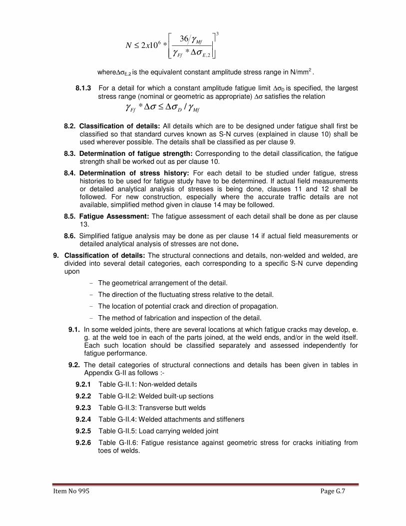
Item No 995 Page G.7
3
2,
6
*
36*102
∆≤
EFf
MfxN
σγ
γ
where∆σE,2 is the equivalent constant amplitude stress range in N/mm2 .
8.1.3 For a detail for which a constant amplitude fatigue limit ∆σD is specified, the largest
stress range (nominal or geometric as appropriate) ∆σ satisfies the relation
MfDFf γσσγ /* ∆≤∆
8.2. Classification of details: All details which are to be designed under fatigue shall first be classified so that standard curves known as S-N curves (explained in clause 10) shall be used wherever possible. The details shall be classified as per clause 9.
8.3. Determination of fatigue strength: Corresponding to the detail classification, the fatigue strength shall be worked out as per clause 10.
8.4. Determination of stress history: For each detail to be studied under fatigue, stress histories to be used for fatigue study have to be determined. If actual field measurements or detailed analytical analysis of stresses is being done, clauses 11 and 12 shall be followed. For new construction, especially where the accurate traffic details are not available, simplified method given in clause 14 may be followed.
8.5. Fatigue Assessment: The fatigue assessment of each detail shall be done as per clause 13.
8.6. Simplified fatigue analysis may be done as per clause 14 if actual field measurements or detailed analytical analysis of stresses are not done.
9. Classification of details: The structural connections and details, non-welded and welded, are divided into several detail categories, each corresponding to a specific S-N curve depending upon
- The geometrical arrangement of the detail.
- The direction of the fluctuating stress relative to the detail.
- The location of potential crack and direction of propagation.
- The method of fabrication and inspection of the detail.
9.1. In some welded joints, there are several locations at which fatigue cracks may develop, e. g. at the weld toe in each of the parts joined, at the weld ends, and/or in the weld itself. Each such location should be classified separately and assessed independently for fatigue performance.
9.2. The detail categories of structural connections and details has been given in tables in Appendix G-II as follows :-
9.2.1 Table G-II.1: Non-welded details
9.2.2 Table G-II.2: Welded built-up sections
9.2.3 Table G-II.3: Transverse butt welds
9.2.4 Table G-II.4: Welded attachments and stiffeners
9.2.5 Table G-II.5: Load carrying welded joint
9.2.6 Table G-II.6: Fatigue resistance against geometric stress for cracks initiating from toes of welds.

Item No 995 Page G.8
NOTE: Table G-II.6 does not cover effects of misalignment. The effect of misalignment has
to be considered explicitly in determination of stress. Further, it does not cover fatigue
initiation from the root followed by propagation through the throat.
10. Methodology for Assessment, Step II: Determination of fatigue strength
10.1. S-N Curves: The fatigue strength for nominal stresses is defined by a series of S-N
curves(log ∆σR – log N, or, log ∆τR – log N), each corresponding to a specific detail category. Each curve is a log-log plot of the stress range against the number of cycles to failure at that stress range where the logarithms are to the base 10. A typical fatigue strength curve is shown in figure 10.1.
Figure 10.1: Typical fatigue strength (S-N) curve
10.2. Parameters of S-N curves
10.2.1 Each detail category is characterized by a number which represents, in N/mm2, the
reference value ∆σC or ∆τC as applicable for the fatigue strength at 2 million cycles.
10.2.2 The S-N curves include the effects due to :-
• Local stress concentration
• Size and shape of acceptable discontinuities
• The stress directions
• Residual stresses
• Metallurgical conditions

Item No 995 Page G.9
Figure 10.2: Fatigue Strength curves for normal stress ranges
10.2.3 S-N curve for constant amplitude normal stress ranges: These curves for different fatigue categories are shown in figure 10.2. Each curve is described as below:
10.2.3.1 From 104 cycles to 5 x 10⁶ cycles, the curve has a negative slope of 3. The
value of ∆σD at 5 x 10⁶ cycles is called constant amplitude fatigue limit. The fatigue strength in this part is defined by:
NR *(∆σR)m = 2 * 106 * (∆σC)m, with m=3 for NR ≤ 5*106
where CCD σσσ ∆=∆
=∆ 7368.0*5
2 31
and NR is the number of cycles to failure corresponding to ∆σR read from the appropriate S-
N curve.
10.2.3.2 From 5 x 10⁶ cycles to 1 x 10⁸ cycles, the curve has a negative slope of 5.
The value of ∆σL at 100 million cycles is called cut off limit. The fatigue strength in this part is defined by:
NR * (∆σR)m = 5 * 106 * (∆σD)m with m=5 for 5*106< NR≤108
where DDL σσσ ∆=∆
=∆ *5493.0*100
5 51
10.2.3.3 Beyond 1 x 10⁸ cycles, the curve has NIL slope and there is no fatigue damage.
10.2.4 S-N curve for constant amplitude shear stress ranges: These curves for different fatigue categories are shown in figure 10.3. Each curve is described as below:

Item No 995 Page G.10
10.2.4.1 From 104 cycles to 1 x 10⁸ cycles, the curve has a negative slope of 5. The
value of ∆τL is the cut off limit at 100 million cycles. The fatigue strength curves for shear stress are defined as:
NR *(∆τR)m = 2 * 106 * (∆τC)m, with m=5 for NR≤ 108
whereCCL τττ ∆=∆
=∆ 4573.0*100
2 51
is the cut off limit at 100 million cycles
10.2.4.2 Beyond 1 x 10⁸ cycles, the curve has NIL slope and there is no fatigue damage.
Figure 10.3: Fatigue Strength curves for shear stress ranges
10.2.5 Equations defining S-N curves: The fatigue strength curves for nominal normal/shear stresses are also defined by
log NR = log a – m * log ∆σR or log NR = log a – m * log ∆τR
where∆σR or ∆τR is the fatigue strength
NR is the corresponding number of cycles to failure of stress range ∆σR or ∆τR
m is the constant slope of the fatigue strength curves
log a is a constant which depends on the specific segment of the fatigue curve
The numerical values for the fatigue strength curves for normal and shear stress ranges as defined by above are given in Tables 10.1 and 10.2 respectively.

Item No 995 Page G.11
Table 10.1: Numerical values for fatigue strength curves for normal stress ranges
Detail Category
∆∆∆∆σσσσC (N/mm2)
log a for NR≤≤≤≤ 108 Stress Range at
Constant amplitude
Fatigue limit (NR = 5*106)
∆∆∆∆σσσσD(N/mm2)
Stress Range at
Cut off limit (NR = 108)
∆∆∆∆σσσσL(N/mm2)
Limiting Stress Range
(NR = 104)
∆∆∆∆σσσσSL(N/mm2)
NR≤≤≤≤ 5 * 106
m = 3
NR≥≥≥≥ 5 * 106
m = 5
160 12.913 17.056 118 65 936
140 12.739 16.766 103 57 819
125 12.592 16.520 92 51 731
112 12.449 16.282 83 45 655
100 12.301 16.036 74 40 585
90 12.164 15.807 66 36 526
80 12.010 15.551 59 32 468
71 11.855 15.292 52 29 415
63 11.699 15.032 46 25 368
56 11.546 14.777 41 23 327
50 11.398 14.531 37 20 292
45 11.261 14.302 33 18 263
40 11.107 14.046 29 16 234
36 10.970 13.817 27 15 211
Table 10.2: Numerical values for fatigue strength curves for shear stress ranges
Detail
Category
∆∆∆∆ττττC(N/mm2)
log a for N ≤≤≤≤ 108
m = 5
Stress Range at Cut
off limit(N = 108)
∆∆∆∆ττττL(N/mm2)
Limiting Stress
Range(N = 104)
∆∆∆∆ττττSL(N/mm2)
100 16.301 46 289
80 15.816 37 231
10.3. Modifications to the fatigue strength
10.3.1 To account for reversal of stresses: In non-welded or stress relieved details the effective stress range to be considered for fatigue assessment shall be determined by adding the tensile portion of the stress range with 70% of the compressive portion of the stress range as shown in figure 10.4.

Item No 995 Page G.12
Figure 10.4: Modified stress range for non-welded or stress relieved details
10.3.2 To account for the influence on the fatigue strength of the thickness of the parent metal in which the potential cracks may initiate and propagate:
10.3.2.1 The reduction in the fatigue strength will be applicable only to those structural details with welds transverse to the direction of the normal stress.
10.3.2.2 Where the material thickness of the structural detail is greater than 25 mm, the effect of thickness shall be accounted for by reducing the fatigue strength as :-
20.0
, )/25(* tRtR σσ ∆=∆ , where 25/t ≤ 1.
10.3.2.3 Where the detail category in the classification tables indicates a specific variation in the fatigue strength with thickness then 10.3.2.1 will not be applicable.
10.3.3 Modified fatigue strength is applicable to structural details duly marked with an asterisk in the detail classification table G.II.5. Such details have been allocated a category lower than the stress range corresponding to 2 million cycles. The classification of such details may be upgraded by one category provided that fatigue strength curves are adopted such that the constant amplitude fatigue limit is at 10 million cycles for a slope of m = 3 as shown in figure 10.5 and the numerical values for the modified fatigue strength curves are as indicated in table 10.3.

Item No 995 Page G.13
Figure 10.5: Modified fatigue Strength Curves
Table 10.3: Numerical values for modified fatigue strength curves for normal stress ranges
Detail
Category
∆∆∆∆σσσσC
(Nominal)
log a for N ≤≤≤≤ 108 Stress Range at
Constant
amplitude
Fatigue limit
(N = 107)
∆∆∆∆σσσσD
(N/mm2)
Stress Range
at
Cut off limit
(N = 108)
∆∆∆∆σσσσL
(N/mm2)
Limiting Stress
Range
(N = 104)
∆∆∆∆σσσσSL
(N/mm2)
N ≤≤≤≤ 107
m = 3
N ≥≥≥≥ 107
m = 5
50*(56) 11.546 14.576 33 21 327
45*(50) 11.398 14.330 29 18 292
36*(40) 11.107 13.845 23 15 234
NOTE: Values in parentheses indicate the next higher category for which the constants are
evaluated as per clause 10.3.3.
11. Determination of stresses to be used for fatigue design: For each structural detail or joint being assessed for fatigue, typical load event (or train) produces a stress history plot, depending on position of the train at different time intervals. A typical stress history with time plot is shown in Figure A.1 of Appendix G-III. These stresses for different positions of train(s) shall be obtained for member(s) as follows:
11.1. Measurements: The stresses measured on members while actual trains/ test trains pass over the bridge and the plot of variation of stresses with position of train can be used for fatigue assessment of existing bridges. Based on these plots, stress history plots shall then be obtained for the other trains plying/ likely to ply on the bridge. For parameters

Item No 995 Page G.14
difficult to replicate/ measure in field, such as impact, suitable modifications shall be made as per Bridge rules. This method captures the actual behaviour of girders. However, if the actual plot shape/ magnitude of stresses measured in field vary too much as compared with the theoretical expected stresses, reasons for the same shall be studied and designer shall decide if the measured stresses are reliable for fatigue assessment studies or not.
11.2. theoretical plot of stress with position of actual/expected moving train loads shall be determined for the fatigue loads specified in clause 6 above. The stresses due to the moving train loads shall be determined on the basis of static linear elastic analysis carried out in accordance with accepted principles and practices, unless otherwise stated or implied, taking into account all axial, bending and shear stresses occurring under the prescribed fatigue loading.
11.3. Stresses for Fatigue Assessment:
11.3.1 For a particular class of construction detail, the stresses to be considered may be nominal stresses or shear stresses or both.
11.3.2 When a constructional detail is defined in the detail classification tables (Table G.II.1 to G.II.5), the nominal stress range shall be used.
11.3.3 The effects of geometric discontinuities which are not part of the constructional detail itself, such as holes, cut-outs or re-entrant corners shall be taken into account separately, either by a special analysis or by the use of appropriate stress concentration factors, to determine the modified nominal stress range.
11.4. Modification in measured/ computed stresses:-
11.4.1 The nominal stresses should be calculated at the location of potential fatigue initiation. No redistribution of loads or stresses is permitted from any consideration whatsoever.
11.4.2 Where applicable, effect of the following should be incorporated in the stress calculations:-
(a) Shear lag, restrained torsion and distortion, transverse stresses and flange
curvature
(b) Effective width of steel plates
(c) Load application away from joints, member eccentricities at joints and rigidity of
joints in triangulated skeletal structures.
(d) Stress concentration effects, when specifically stated as a requirement for a detail
or joint, which shall be accounted for by using an appropriate stress concentration
factor.
11.4.3 The effects of the following need not be included in the stress calculations
(a) Residual stresses.
(b) Eccentricities arising in a standard detail.
(c) Standard stress concentration associated with a detail as given in tables G-II.1 to
G-II.5 which has already been considered in the fatigue detail category.
11.5. s 11.7 and 11.8 for stresses in parent material and stresses in welds respectively.
11.6. Modification of stress ranges based on geometric stress range:
11.6.1 Where abrupt changes of section occur close to the potential crack locations (for details not covered in tables G.II.1 to G.II.5), high stress gradients occur close to a weld in toe joints (covered in Table G-II.6), geometric stress range shall be used.
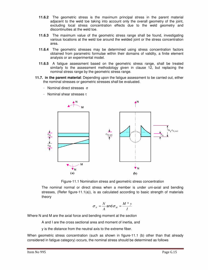
Item No 995 Page G.15
11.6.2 The geometric stress is the maximum principal stress in the parent material adjacent to the weld toe taking into account only the overall geometry of the joint, excluding local stress concentration effects due to the weld geometry and discontinuities at the weld toe.
11.6.3 The maximum value of the geometric stress range shall be found, investigating various locations at the weld toe around the welded joint or the stress concentration area.
11.6.4 The geometric stresses may be determined using stress concentration factors obtained from parametric formulae within their domains of validity, a finite element analysis or an experimental model.
11.6.5 A fatigue assessment based on the geometric stress range, shall be treated similarly to the assessment methodology given in clause 12, but replacing the nominal stress range by the geometric stress range.
11.7. in the parent material: Depending upon the fatigue assessment to be carried out, either the nominal stresses or geometric stresses shall be evaluated.
- Nominal direct stresses σ
- Nominal shear stresses τ
Figure-11.1 Nomination stress and geometric stress concentration
The nominal normal or direct stress when a member is under uni-axial and bending
stresses, (Refer figure-11.1(a)), is as calculated according to basic strength of materials
theory
A
NN =σ and
I
yMM
*=σ
Where N and M are the axial force and bending moment at the section
A and I are the cross sectional area and moment of inertia, and
y is the distance from the neutral axis to the extreme fiber.
When geometric stress concentration (such as shown in figure-11.1 (b) other than that already
considered in fatigue category) occurs, the nominal stress should be determined as follows
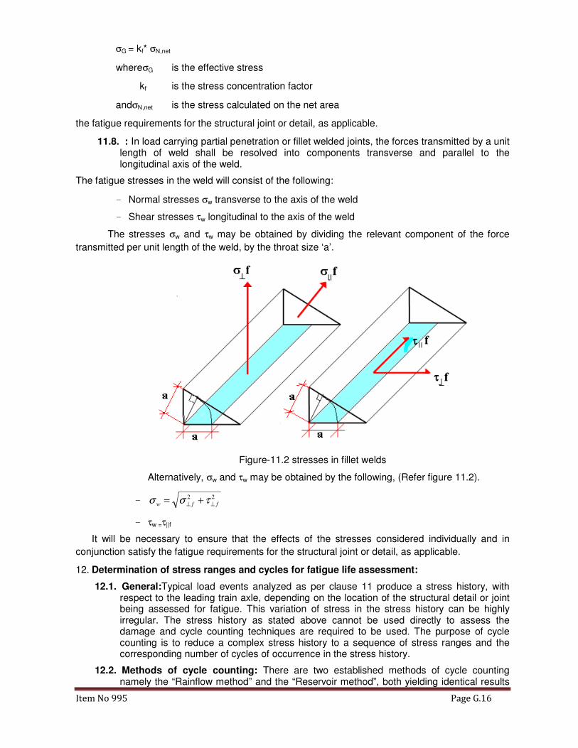
Item No 995 Page G.16
σG = kf* σN,net
whereσG is the effective stress
kf is the stress concentration factor
andσN,net is the stress calculated on the net area
the fatigue requirements for the structural joint or detail, as applicable.
11.8. : In load carrying partial penetration or fillet welded joints, the forces transmitted by a unit length of weld shall be resolved into components transverse and parallel to the longitudinal axis of the weld.
The fatigue stresses in the weld will consist of the following:
- Normal stresses σw transverse to the axis of the weld
- Shear stresses τw longitudinal to the axis of the weld
The stresses σw and τw may be obtained by dividing the relevant component of the force
transmitted per unit length of the weld, by the throat size ‘a’.
Figure-11.2 stresses in fillet welds
Alternatively, σw and τw may be obtained by the following, (Refer figure 11.2).
- 22
ffw ⊥⊥ += τσσ
- τw =τ||f
It will be necessary to ensure that the effects of the stresses considered individually and in
conjunction satisfy the fatigue requirements for the structural joint or detail, as applicable.
12. Determination of stress ranges and cycles for fatigue life assessment:
12.1. General:Typical load events analyzed as per clause 11 produce a stress history, with respect to the leading train axle, depending on the location of the structural detail or joint being assessed for fatigue. This variation of stress in the stress history can be highly irregular. The stress history as stated above cannot be used directly to assess the damage and cycle counting techniques are required to be used. The purpose of cycle counting is to reduce a complex stress history to a sequence of stress ranges and the corresponding number of cycles of occurrence in the stress history.
12.2. Methods of cycle counting: There are two established methods of cycle counting namely the “Rainflow method” and the “Reservoir method”, both yielding identical results

Item No 995 Page G.17
provided that rainflow counting begins with the highest peak in the loading event. Generally, rainflow counting is more suited to computer analyses of long stress histories, whereas the reservoir method is most convenient for graphical analyses of short histories.
12.2.1 Determination of stress ranges and cycles by the reservoir method: The method consists of imagining the stress history as the section of a reservoir which is drained successively from each of the lowest points till the reservoir is empty. Each draining operation is considered to be equivalent to one cycle of a stress range equal in magnitude to the maximum height of water drained in that particular operation (see Appendix G-III).
12.2.2 Determination of stress ranges and cycles by the rainflow method: The rainflow method as the name suggests counts half cycles based on the visualization of the complex stress history as a sequence of pagoda roofs over which rain tickles down. In order to achieve the above the stress history is rotated by 900 (see Appendix G-III). Counting of cycles shall be done as per rules given in Appendix G-III.
12.3. The values of stress ranges for which cycles are thus counted might be quite variable in magnitude. For further computations, the values of stress ranges are grouped together in different stress range slabs to get the stress histogram. The fatigue assessment is done using this stress histogram. Stress histogram for the stress history has been worked out in clause A3.3 of Appendix G-III.
12.4. For each stress range slab in stress histogram, the corresponding fatigue life can be worked out for the appropriate SN curve applicable to the member detail.
13. Fatigue assessment:-Fatigue assessment refers either to checking if a member has been designed with adequate fatigue life or to verifying if the residual fatigue life of a member is adequate. Stresses determined/ modified in accordance with clause 12 shall be used for this purpose.
13.1. The assessment for fatigue shall be carried out either
- in terms of cumulative damage by comparing the applied damage to the limiting damage, or
- in terms of the equivalent stress range by comparing it with the fatigue strength for a given number of stress cycles.
13.2. Fatigue assessment based on nominal stress ranges:
13.2.1 Constant amplitude loading
For constant amplitude loading the fatigue assessment criterion is:
��� ∗ ∆� ≤ ∆��/���or��� ∗ ∆� ≤ ∆��/���
where ∆σ (or ∆τ) is the nominal stress range.
∆σR (or ∆τR) is the fatigue strength for the relevant detail category for the total number
of cycles N during the required design life.
and � and � shall be as per clause 7.4
13.2.2 Variable amplitude loading
13.2.2.1 For variable amplitude loading defined by a design spectrum, the fatigue assessment shall be based on Palmgren-Miner rule of cumulative damage given in 13.2.2.3 below.
13.2.2.2 If the maximum stress range due to the variable amplitude loading is higher than the constant amplitude fatigue limit, then one of the following types of fatigue assessment shall be made:
- Cumulative damage
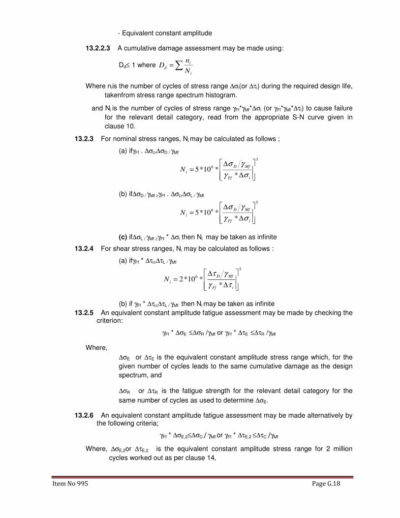
Item No 995 Page G.18
- Equivalent constant amplitude
13.2.2.3 A cumulative damage assessment may be made using:
Dd≤ 1 where ∑=i
i
dN
nD
Where niis the number of cycles of stress range ∆σi(or ∆τi) during the required design life,
takenfrom stress range spectrum histogram.
and Ni is the number of cycles of stress range γFf*γMf*∆σi (or γFf*γMf*∆τi) to cause failure
for the relevant detail category, read from the appropriate S-N curve given in
clause 10.
13.2.3 For nominal stress ranges, Ni may be calculated as follows ;
(a) ifγFf . ∆σi≥∆σD / γMf 3
6
**10*5
∆
∆=
iFf
MfD
iNσγ
γσ
(b) if∆σD / γMf ≥γFf . ∆σi≥∆σL / γMf 5
6
**10*5
∆
∆=
iFf
MfD
iNσγ
γσ
(c) if∆σL / γMf ≥γFf * ∆σi then Ni may be taken as infinite
13.2.4 For shear stress ranges, Ni may be calculated as follows :
(a) ifγFf * ∆τi≥∆τL / γMf 5
6
**10*2
∆
∆=
iFf
MfD
iNτγ
γτ
(b) if γFf * ∆τi≤∆τL / γMf then Ni may be taken as infinite
13.2.5 An equivalent constant amplitude fatigue assessment may be made by checking the criterion:
γFf * ∆σE ≤∆σR /γMf or γFf * ∆τE ≤∆τR /γMf
Where,
∆σE or ∆τE is the equivalent constant amplitude stress range which, for the
given number of cycles leads to the same cumulative damage as the design
spectrum, and
∆σR or ∆τR is the fatigue strength for the relevant detail category for the
same number of cycles as used to determine ∆σE.
13.2.6 An equivalent constant amplitude fatigue assessment may be made alternatively by the following criteria;
γFf * ∆σE,2≤∆σC / γMf or γFf * ∆τE,2 ≤∆τC /γMf
Where, ∆σE,2or ∆τE,2 is the equivalent constant amplitude stress range for 2 million
cycles worked out as per clause 14,

Item No 995 Page G.19
And ∆σC or ∆τC is the reference value of the fatigue strength for the relevant detail
(also at 2 million cycles).
13.3. Combination of normal and shear stress ranges:
13.3.1 In the case of a combination of normal and shear stresses the fatigue assessment shall consider their combined effects.
13.3.2 If the equivalent nominal shear stress range is less than 15 % of the equivalent nominal normal stress range, the effects of the shear stress range may be neglected.
13.3.3 At locations other than weld throats, if the normal and shear stresses induced by the same loading event vary simultaneously, or if the plane of the maximum principal stress does not change significantly in the course of a loading event, the maximum principal stress range may be used.
13.3.4 If, at the same location, normal and shear stresses vary independently, the components of damage due to normal and shear stresses shall be determined separately in accordance with the Palmgren-Miner rule and then combined in accordance with
Dd,σ+ Dd,τ≤ 1
where Dd,σ = ∑(ni / Ni ) for normal stress ranges ∆σi
and Dd,τ = ∑(ni / Ni ) for shear stress ranges ∆τi
13.3.5 The criteria specified in 13.3.4 for equivalent constant amplitude stress ranges assumes the form
1**
53
≤
∆
∆+
∆
∆
MfR
EFf
MfR
EFf
γτ
τγ
γσ
σγ
13.3.6 An equivalent constant amplitude fatigue assessment may, alternatively, be made by the following criterion
1**
5
2,
3
2, ≤
∆
∆+
∆
∆
MfC
EFf
MfC
EFf
γτ
τγ
γσ
σγ
13.3.7 Stress ranges in welds shall be determined as specified in Clause 11.6. The components of damage for normal and shear stresses shall be assessed in accordance with the Palmgren-Miner rule and then combined in accordance with
Dd,σ+ Dd,τ≤ 1
where Dd,σ = ∑(ni / Ni ) for normal stress ranges σwf.
and Dd,τ = ∑(ni / Ni ) for shear stress ranges ∆τwf.
14. Simplified Approach if actual field measurements or detailed analytical analysis of stresses is not done: For the simplified fatigue assessment, the following procedure may be adopted to determine the design stress spectrum:
14.1. For a detail or structural connection being assessed for fatigue, the maximum stress
σP,maxor τP,maxand the minimum stress σP,minor τP,minshould be determined for the live loads specified in clause 6. Instead of actual train loads, the Equivalent Uniformly distributed loads as specified in IRS Bridge Rules may be used.
14.2. The reference stress range ∆σP (or∆τP) for determining the damage due to the stress spectrum should be obtained from:

Item No 995 Page G.20
min,max, PPP σσσ −=∆ ormin,max, PPP τττ −=∆
14.3. Modification of the above stress range may be done in accordance with clause 10.3, 11.3 and 11.4, if applicable.
14.4. Design value of equivalent constant amplitude stress range: The design value of
equivalent constant amplitude stress range (related to NCi.e. 2 x 10⁶ cycles, ∆σE,2or ∆τE,2) shall be worked out by multiplying the modified stress range worked out as per clause 14.3
above by damage equivalent factor for railway bridges, λ worked out as per clause 14.6 below.
14.5. Fatigue assessment
The fatigue assessment shall be carried out by ensuring the satisfaction of the following
criteria:
γFf *∆σE,2 ≤∆σC / γMf
and γFf *∆τE,2 ≤∆τC / γMf
Where ∆σC or ∆τC is the reference value of the fatigue strength for the relevant detail (at 2
million cycles).
14.6. Damage equivalence factors
14.6.1 The damage equivalent factor for railway bridges should be determined from:
λ = λ1 * λ2 * λ3 * λ4
subject to the condition that λ≤λmax whereλmax =1.4
Where,
λ1 is a factor that takes into account the damaging effect of traffic and depends
on the base length of the longest loop of the influence line diagram
λ2 is a factor that takes into account the annual traffic volume in million tons
λ3 is a factor that takes into account the design life of the bridge in years
λ4 is a factor to be taken into account when the bridge structure is loaded on
more than one track
λmax is the maximum λ value taking into account the fatigue limit
14.6.2 The value of λ1 may be obtained from tables 14.6.2 (1) and 14.6.2 (2) 25t loading – 2008 and 32.5t loading (DFC) respectively as a function of the loaded length for the train types included in respective traffic models. The loaded length shall depend upon the influence line diagram of the structural element or detail/connection under consideration. For simplified analysis the maxima for each length category could be adopted. For routes with train types other than those considered above, the designer
may use alternative values of λ1.
Table 14.6.2 (1): λλλλ1 for 25 T Loading
Span
(m)
Train-
1
Train-
2
Train-
3
Train-
4
Train-
5
Train-
6
Train-
7
Train-
8
Train-
9
Train-
10
Train-
11
0.50 1.30 1.34 1.45 1.28 1.45 1.44 1.48 1.53 1.36 1.09 0.88
1.00 1.29 1.32 1.43 1.28 1.43 1.43 1.48 1.53 1.35 1.08 0.89
1.50 1.28 1.31 1.42 1.27 1.42 1.42 1.47 1.52 1.35 1.07 0.90
2.00 1.27 1.30 1.40 1.27 1.40 1.41 1.47 1.52 1.35 1.06 0.90
2.50 1.26 1.29 1.38 1.26 1.37 1.39 1.46 1.51 1.34 1.05 0.91

Item No 995 Page G.21
Span
(m)
Train-
1
Train-
2
Train-
3
Train-
4
Train-
5
Train-
6
Train-
7
Train-
8
Train-
9
Train-
10
Train-
11
3.00 1.24 1.28 1.36 1.25 1.34 1.38 1.45 1.50 1.34 1.04 0.92
3.50 1.22 1.26 1.34 1.23 1.32 1.36 1.44 1.49 1.33 1.03 0.93
4.00 1.20 1.25 1.32 1.22 1.30 1.34 1.43 1.47 1.31 1.02 0.94
4.50 1.18 1.23 1.30 1.21 1.28 1.31 1.42 1.46 1.30 1.00 0.95
5.00 1.17 1.21 1.28 1.19 1.26 1.27 1.41 1.45 1.28 0.99 0.96
6.00 1.12 1.17 1.24 1.15 1.23 1.21 1.39 1.42 1.24 0.96 0.97
7.00 1.08 1.14 1.19 1.11 1.18 1.16 1.37 1.39 1.19 0.93 0.98
8.00 1.05 1.12 1.17 1.09 1.16 1.12 1.38 1.37 1.14 0.91 1.00
9.00 1.03 1.11 1.15 1.07 1.13 1.08 1.38 1.36 1.09 0.90 1.02
10.00 0.96 1.03 1.12 1.15 1.08 1.10 1.37 1.37 1.08 0.89 0.99
12.50 0.89 0.98 1.05 1.06 1.03 1.02 1.32 1.32 1.00 0.86 1.01
15.00 0.87 0.92 1.00 1.01 1.05 1.00 1.30 1.31 0.99 0.83 1.02
17.50 0.82 0.86 0.94 0.93 1.04 0.94 1.24 1.24 0.93 0.78 0.98
20.00 0.83 0.86 0.99 0.94 1.07 0.89 1.13 1.09 0.89 0.79 1.01
25.00 0.76 0.86 0.93 0.85 1.08 0.87 1.13 1.11 0.87 0.75 0.99
30.00 0.77 0.82 0.84 0.80 1.09 0.88 0.98 1.10 0.87 0.69 0.96
35.00 0.73 0.75 0.78 0.76 0.87 0.86 0.93 1.09 0.86 0.66 0.90
40.00 0.66 0.68 0.70 0.73 0.85 0.78 0.84 1.07 0.78 0.63 0.75
45.00 0.64 0.66 0.68 0.77 0.81 0.77 0.82 1.01 0.78 0.63 0.65
50.00 0.62 0.63 0.65 0.77 0.80 0.75 0.79 0.91 0.76 0.62 0.66
60.00 0.59 0.60 0.62 0.77 0.77 0.74 0.77 0.78 0.74 0.60 0.67
70.00 0.58 0.59 0.60 0.75 0.76 0.75 0.77 0.78 0.75 0.61 0.64
80.00 0.56 0.58 0.59 0.66 0.76 0.74 0.76 0.77 0.75 0.60 0.63
90.00 0.56 0.57 0.58 0.64 0.76 0.72 0.75 0.76 0.75 0.58 0.63
100.00 0.55 0.56 0.58 0.61 0.76 0.73 0.74 0.75 0.74 0.55 0.63
Table 14.6.2 (2): λλλλ1 for 32.5 T Loading
Span (m) Train-1 Train-2 Train-3 Train-4 Train-5 Train-6 Train-7
0.50 1.53 1.60 1.39 1.59 1.30 1.11 0.86
1.00 1.52 1.59 1.38 1.58 1.28 1.10 0.87
1.50 1.52 1.58 1.37 1.57 1.27 1.09 0.87
2.00 1.52 1.58 1.36 1.57 1.25 1.09 0.88
2.50 1.51 1.57 1.36 1.56 1.24 1.08 0.89
3.00 1.51 1.56 1.35 1.55 1.23 1.08 0.89
3.50 1.51 1.55 1.34 1.54 1.21 1.07 0.90
4.00 1.50 1.54 1.34 1.53 1.20 1.07 0.91
4.50 1.49 1.53 1.33 1.51 1.19 1.06 0.92
5.00 1.47 1.52 1.32 1.50 1.17 1.05 0.93
6.00 1.43 1.50 1.29 1.46 1.14 1.03 0.95
7.00 1.38 1.48 1.28 1.44 1.11 1.02 0.97
8.00 1.34 1.46 1.27 1.42 1.09 1.01 0.99
9.00 1.31 1.45 1.25 1.39 1.06 1.00 1.01
10.00 1.31 1.47 1.30 1.39 1.18 1.06 1.06
12.50 1.22 1.40 1.25 1.33 1.12 1.03 1.09
15.00 1.16 1.34 1.20 1.28 1.08 1.00 1.08
17.50 1.10 1.28 1.15 1.23 1.05 0.97 1.04
20.00 0.96 1.18 1.04 1.15 1.17 1.08 1.08
25.00 0.89 1.11 0.97 0.97 1.10 0.88 0.99
30.00 0.88 1.10 0.88 0.89 0.95 0.75 0.93

Item No 995 Page G.22
Span (m) Train-1 Train-2 Train-3 Train-4 Train-5 Train-6 Train-7
35.00 0.84 1.06 0.85 0.84 0.89 0.75 0.90
40.00 0.84 0.89 0.84 0.84 0.84 0.76 0.81
45.00 0.81 0.84 0.80 0.81 0.80 0.73 0.68
50.00 0.80 0.82 0.79 0.80 0.77 0.73 0.70
60.00 0.74 0.75 0.73 0.74 0.70 0.66 0.67
70.00 0.72 0.74 0.70 0.73 0.69 0.63 0.65
80.00 0.72 0.77 0.70 0.76 0.69 0.63 0.63
90.00 0.74 0.76 0.70 0.75 0.70 0.61 0.63
100.00 0.74 0.75 0.70 0.75 0.69 0.60 0.64
14.6.3 The loaded length for determination of appropriate λ1 should be taken as follows:
(a) for moments:
- For a simply supported span, the span length, L
- For cross girders supporting rail bearers (or stringers), the sum of the spans of the rail bearers (or stringers) carried by the cross girder.
(b) for shear for a simply supported span
- For the support section, the span length.
- For the mid-span section, 0.4 * the span under consideration.
(c) for axial force in members of a triangulated truss
- Base length of loop containing the largest ordinate (+ve or -ve) in member being assessed for fatigue as per the Influence Line Diagram (ILD) of the member (see Fig. 14.1).
(d) In other cases
- the same as for moments.
Figure 14.1: Loaded lengths for finding λ1.
U1 2U 3U 4U 5U 6U 7U
1L 2L 3L 4L 5L 6L 7L 8L0L
27000 mm
36000 mm
Figure - 9 (a) Loaded Length for Diagonal U -L3 4
Loaded Length
Figure - 9 (b) Loaded Length for Vertical U -L3
7875 mmLoaded Length
3
0L L 2 4L 8L
Figure - 9 (c) Loaded Length for Bottom Chord L -L & L -L0 1 1 2
Note :- (+) For Tension and (-) For Compression
(+)
(-)
(+)
63000 Loaded LengthL 0 1L
(+)
L 8
Figure 14.1 (a)
Figure 14.1 (b)
Figure 14.1 (c)

Item No 995 Page G.23
14.6.4 The value of λ2, in terms of the annual volume of traffic may be obtained from the following expression where Ta is the annual volume of traffic expressed in million tons:
2036.0
2 *5193.0 aT=λ
14.6.5 The value of λ3, in terms of the design life may be calculated from the following expression where LD is the design life in years:-
2048.0
3 *3899.0 DL=λ
14.6.6 The value of λ4, assuming 15% of the total traffic on both tracks crosses whilst on the bridge, shall be obtained from
9371.0*7280.0*7926.0 2
4 +−= aaλ
Where a = ∆σ1 / ∆σ1+2
∆σ1 = Stress range at the section being checked due to train on one track.
∆σ1+2 = Stress range at the same section due to train load on two tracks.
The values of λ4 may be calculated for other proportions of crossing traffic from
( ) ( )[ ]5 55
4 )11 aann −+−+=λ
Where, n is the proportion of traffic that crosses simultaneously on the bridge.

Appendix G.I
Item No 995 Page G.24
Table 1(a) – Traffic Models for 25t Loading
Type of Train
Tra
in N
o.
Train Composition
Weight per train (t)
GMT/ Train
Class of Traffic
Heavy Freight Traffic
(100 GMT)
Mixed Traffic Lines with Heavy Traffic (70 GMT)
Sub Urban Traffic (60
GMT)
Mixed Traffic Lines with Light Traffic (40GMT)
No. of Trains
GMT No. of Trains
GMT No. of Trains
GMT No. of Trains
GMT
Passenger
1 1+15ICF COACH NON AC
900 0.33 3 1.0 6 2.0 - - 5 1.7
2 2+22 ICF COACH NON AC
1400 0.51 2 1.0 10 5.1 7 3.57 5 2.6
3 2+26 COACH AC 1700 0.62 - - 14 8.7 7 4.34 - -
4 EMU12 700 0.26 - - - - 200 52.0 - -
Freight
5 2(22.5T)+40 BOXN 4270 1.56 2 3.1 - - - - 4 6.24
6 2(25T)+55 BOXN 5800 2.12 8 16.96 4 8.48 - - 9 19.08
7 2E(2+55 BOXN) 11540 4.21 10 42.1 6 25.21 - - 1 4.21
8 2D(2+55 BOXN) 11600 4.23 8 33.84 5 21.15 - - 1 4.23
9 Bo-BO +40 BOXN 4200 1.53 2 3.06
Freight empty
10 2(25T)+55BOXN 1686 0.61 - - - - - - 1 0.61
11 2(22.5T)+40 BOXN 1278 0.47 - - - - - - 2 0.9
Total 35 101.06 45 70.64 214 59.91 28 39.57

Appendix G.I
Item No 995 Page G.25
1. PASSENGER TRAIN
ONE 25 t. LOCO + 15 ICF COACH NON AC
TOTAL Wt. = 930 t25t 13t
28
96
15 UNITS @ 22297
25t 25t 25t 25t 25t
20
50
19
50
55
60
19
50
20
50
52
79
13t 13t 13t
28
96
118
87
2. PASSENGER TRAIN
TWO 25 t. LOCO + 22 ICF COACH NON AC
25t25t
205
0
289
6
13t13t13t25t25t25t25t
527
9
205
0
195
0
556
0
195
0
1188
7
289
6
22 UNITS @ 22297
13t
2 UNITS @ 19500
ONE UNIT @ 19500
TOTAL Wt. = 1444 t
29
70
23
09
297
0
230
9
Train type CompositionTotal
Diagram
Type - 1 1L+15 ICF 348.676 930
(Non AC)
(m)
(Non AC)
2+22 ICFType - 2 524.255 1444
COACH
COACH
(Contd.)
1

Appendix G.I
Item No 995 Page G.26
3. PASSENGER TRAIN
TWO 25 t. LOCO + 26 COACH AC
25t25t
2050
2896
16.25t25t25t25t25t
5279
2050
1950
5560
1950
118
87
2896
26 UNITS @ 22297
TOTAL Wt. = 1990 t
2 UNITS @ 19500
16.25t 16.25t 16.25t
13t
EMU 12 (3x4 UNITS)
4. PASSENGER TRAIN
2896
4 UNITS @ 64563
13t 13t 13t 20t 13t 13t 13t 13t
11
734
2896
3995
2896
11
734
2896
3995
2896
11
734
2896
20t 20t 20t
TOTAL Wt. = 736 t
2970
2309
1998
1998
Type - 3 2+26 COACH 613.443 1990(AC)
EMU 12Type - 4 254.257 736
Train type CompositionTotal
Diagram(m)
(Contd.)
(Contd.)
1

Appendix G.I
Item No 995 Page G.27
5. FREIGHT TRAIN
TWO 22.5T LOCO + 40 BOXN
TOTAL Wt. = 4270 t25t
40 UNITS @ 10713
16
50
16
50
64
00
16
50
16
50
20
00
6. FREIGHT TRAIN
TWO 25T LOCO + 55 BOXN
45
24
2 UNITS @ 16000
20
00
25t 25t 25t
55 UNITS @ 10713
25t
2 UNITS @ 19500
20
50
19
50
55
60
19
50
20
50
25t
20
00
25t
45
24
25t
20
00
TOTAL Wt. = 5800 t25t25t25t25t25t25t
15
00
10
94
.5
25
94
.5
29
70
40
64
.5
10
94
.5
Type - 5 2(22.5t)+40 457.925 4270
2(25T)+55Type - 6 624.15 5800
BOXN
BOXN
Train type CompositionTotal
Diagram(m)
(Contd.)
(Contd.)
1

Appendix G.I
Item No 995 Page G.28
Table 6.4 (a) – Traffic Modes for 32.5t Loading
7. FREIGHT TRAIN
2 (TWO ELECTRIC LOCO + 55 BOXN)
55 UNITS @ 10713
25t
2 UNITS @ 31110
280
0
565
0
280
0
25t
200
0
25t
452
4
25t
200
0
TOTAL Wt. = 5700 t25t25t25t25t
55 UNITS @ 10713
25t
2 (TWO DIESEL LOCO + 55 BOXN)
8. FREIGHT TRAIN
25t
2 UNITS @ 22415.2
1850
25t
9548
25t
1850
25t
2000
25t 25t
4524
2000
25tTOTAL Wt. = 5800 t
25t
1850
25t
1850
215
0
3244.5
1094.5
TWO SUCH UNITS
TWO SUCH UNITS
2733.6
3828.1
1094.5
Type - 7 2E(2+55 1236.33 11400
2D(2+55Type - 8 1262.62 11600
BOXN)
BOXN)
Train type CompositionTotal
Diagram(m)
(Contd.)
(Contd.)
1

Appendix G.I
Item No 995 Page G.29
9. FREIGHT TRAIN
TWO BO-BO + 40 BOXN
40 UNITS @ 10713
25t
2 UNIT @ 31110
2800
5650
2800
25t
2000
25t
4524
25t
2000
TOTAL Wt. = 4200 t25t25t25t25t
55 UNITS @ 10713
TWO 25T LOCO + 55 BOXN
10. FREIGHT EMPTY TRAIN
25t
2 UNITS @ 1950020
50
25t
55
60
25t
20
50
25t
20
00
6.3t
45
24
20
00
TOTAL Wt. = 1686 t25t
19
50
25t
19
50
6.3t 6.3t 6.3t
2150
32
44
.5
109
4.5
29
70
40
64.5
10
94
.5
Type - 9 BO-BO+40 456.375 4200
2(25T)+55Type - 10 624.15 1686
BOXN
BOXN
Train type CompositionTotal
Diagram(m)
(Contd.)
(Contd.)
1

Appendix G.I
Item No 995 Page G.30
Train type CompositionTotal
Diagram(m)
(Contd.)
11. FREIGHT EMPTY TRAIN
TWO 22.5T LOCO + 40 BOXN
2(22.5T)+40Type - 11
BOXN
457.925 1278
15
00
6.3t
20
00
40 UNITS @ 107132 UNITS @ 16000
16
50
16
50
64
00
16
50
6.3t
20
00
25
94
.5
16
50
6.3t
45
24
TOTAL Wt. = 1278 t
10
94
.5
6.3t
1

Appendix G.I
Item No 995 Page G.31
Table 2 (a) – Traffic Models 32.5t (DFC) Loading
Type of
Train
Train
for-
mation
No.
Train
Composition
Total
length
of
Train
(m)
Weight
per
Train
(t)
GMT
per
train
Class of Traffic
Heavy
(150 GMT)
Medium
(100 GMT)
Light
(50 GMT)
No. of
Trains
per
day
GMT
No. of
Trains
per
day
GMT
No. of
Trains
per
day
GMT
Freight
trains
loaded
(Gondola
Type
Wagon)
1 Two 6 axle
loco as
proposed +
40
473.35 5500 2.07 3 6.12 2 4.08 4 8.16
2 2(2WDG2
Type +55)
1256.43 14900 5.44 4 21.988 2 10.994 1 5.497
3 One 8-axle
loco + 40
459.62 5400 1.97 15 29.895 11 21.923 2 3.986
4 3WDG2
Type+75
861.975 10200 3.72 6 22.536 4 15.024 2 7.512
5 3WAG6C
+75
865.161 10155 3.7 18 66.474 12 44.316 6 22.158
Freight
trains
empty
6 2WDG2
Type+40
467.52 1332 0.486 3 1.524 2 1.16 3 1.524
7 2MBG Type
loco +55
621.215 1689 0.616 2 1.232 4 2.464 2 1.232

Appendix G.I
Item No 995 Page G.32
2

Appendix G.I
Item No 995 Page G.33
2
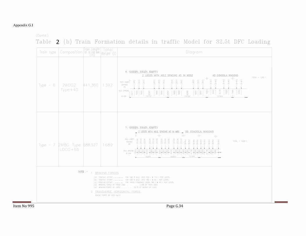
Appendix G.I
Item No 995 Page G.34
2

Appendix G-II
Item No 995 Page G.35
Table G-II.1 Non-welded details
Detail
category
Constructional Detail Description Requirements
160
NOTE: The fatigue strength curve associated with category 160 is the highest. No detail can reach a better fatigue strength at any number of cycles.
21
Rolled and extruded products:
1) Plates and flats
2) Rolled sections
Details 1) to 2)
Sharp edges, surface and rolling
flaws to be improved by grinding
until removed and smooth
transition achieved.
125
3
3) Sheared or gas cut plates:
Machine gas cut or sheared material subsequently dressed to remove all edge discontinuities.
3) All visible signs of edge discontinuities to be removed. The cut areas are to be machined or ground and all burrs to be removed.
Any machinery scratches for example from grinding operations can only be parallel to the stresses.
Detail 3
- Re-entrant corners to be improved by grinding (slope < ¼) or evaluated using the appropriate stress concentration factors.
- No repair by weld refill.

Appendix G-II
Item No 995 Page G.36
For detail 1-3 made of weathering steel use the next lower category
112
4
4) Double covered symmetrical joint with preloaded high strength bolts.
4) ∆σto be calculated on the gross cross-section.
90
5
5) Double covered joint with fitted or non preloaded bolts.
5) ∆σto be calculated on the net cross section.
6
6) One sided connection with preloaded H.S.B.
6) ∆σto be calculated on the gross cross-section.
7
7) Structural element with holes subject to bending and axial forces.
7) ∆σto be calculated on the net cross- section.

Appendix G-II
Item No 995 Page G.37
100
M=5
7a) & 7b) Rolled and extruded products, as in details 1) and 2) above
7a) & 7b) ∆τ calculated from:
τ =� �(�)
� �
80
8
8) One sided connection with fitted bolts or rivets.
8) ∆σto be calculated on the net cross-section.
50
9) Bolts and rods with rolled or cut thread in tension.
For large diameters (anchor
bolts) the size effect has to be
taken into account with ks
Size effect for φ>30mm
ks=(30/φ)0.25.
Where, φ is the nominal
diameter of the bolt or rod.
9) ∆σto be calculated using the tensile stress area of the bolt. Bending and tension resulting from prying effects and bending stresses from other sources must be taken into account.
For preloaded bolts, the reduction of the stress range may be taken into account.

Appendix G-II
Item No 995 Page G.38
100
m = 5
10) Rivets or Bolts in single or double shear. Thread not in the shear plane
- Fitted bolts
- Normal bolts without load reversal (bolts of property class 6.6, 8.8 or 10.9)
10) ∆τcalculated on the shank area of the bolt.

Appendix G-II
Item No 995 Page G.39
Table G-II.2 Welded built-up sections
Detail
category
Constructional Detail Description Requirements
125
1 2
Continuous longitudinal welds:
1) Automatic butt welds carried out from both sides.
2) Automatic fillet welds Cover plate ends to be checked using detail 5) or 6) Table G-II.5.
Details 1) to 2)
No stop/start position is
permitted except when the repair
is performed and inspection is
carried out to verify the proper
execution of the repair.
112
4
3
3) Automatic fillet or butt weld carried out from both sides but containing stop/start positions.
4) Automatic butt welds made from one side only, with a continuous backing bar, but without stop/start positions.
4) When this detail contains stop/start positions category 100 to be used.
100 65
5) Manual fillet or butt weld.
6) Manual or automatic butt weld carried out from one side only, particularly for box girders.
6) A very good fit between the flange and web plates is essential. The web edge to be prepared such that the root face is adequate for the achievement of regular root penetration without break-out.

Appendix G-II
Item No 995 Page G.40
100
7
7) Repaired automatic or manual fillet or butt welds for categories 1-6 above.
7) Improvement by grinding performed by specialist to remove all visible signs and adequate verification can restore the original category.
80
8) Intermittent longitudinal fillet welds.
8) ∆σbased on normal stress in flange.
71
9
9) Longitudinal butt weld, fillet weld or intermittent weld with cope holes, cope holes not higher than 60mm.
9) ∆σbased on normal stress in flange.
125
10
10) Longitudinal butt welds, both sides ground flush parallel to load direction, 100% NDT.
112 10) No grinding and no start/stop.
90 10) With start/stop positions.

Appendix G-II
Item No 995 Page G.41
Table G-II.3 Transverse butt welds
Detail category
Constructional Detail Description Requirements
112
Size effect
for t>25mm:
ks=(25/t)0.2
2a
2
< 1/4
3
<slope 1/4 t
1
t
Without backing bar:
1) Transverse splice in plate and flats
2) Flange and web splices in plate girders before assembly.
2a) Full cross-section butt welds of rolled sections without cope holes.
3) Transverse splices in plates or flats tapered in width or in thickness, with a slope < ¼.
Details 1, 2 and 3:
- All welds ground flush to plate surface parallel to direction of the arrow.
- Weld run-on and run-off pieces to be used and subsequently removed, plate edge to be ground flush in direction of stress.
- Welded from both sides: checked by NDT
Detail 2 a)
Rolled sections with the same
dimensions without tolerance
differences or cut and rewelded.
90
Size effect
for t>25mm:
ks=(25/t)0.2
< 0 . 1 bb
4 a
4
t < t
< 1 / 4
s l o p e 1 / 4
5
4) Transverse splices in plates or flats.
4a)Full cross-section butt welds of rolled sections without cope holes.
5) Transverse splices in plates or flats tapered in width or in thickness with a slope < ¼. Translation of welds to be machined notch free.
- The height of the weld convexity to be not greater than 10% of the weld width, with smooth transition to the plate surface.
- Weld run-on and run-off pieces to be used and subsequently removed, plate edges to be ground flush in direction of stress.
- Welded from both sides; checked by NDT.
Details 4 and 5
Welds made in flat position.

Appendix G-II
Item No 995 Page G.42
90
Size effect
for
t>25mm:
ks=(25/t)0.2
4b
4b)Full cross-section butt welds of rolled sections with cope holes.
- All weld ground flush to plate surface parallel to direction of the arrow.
- Weld run-on and run-off pieces to be used and subsequently removed, plate edges to be ground flush in direction of stress.
- Welded from both sides; checked by NDT.
- Rolled sections with the same dimensions without tolerance differences.
80
Size effect
for
t>25mm:
ks=(25/t)0.2
b< 0.2b t
7
6
6a
6) Transverse splices in welded plate girders without cope hole.
6a) Full cross-section butt welds of rolled sections with cope holes.
7) Transverse splice in plates, flats, rolled sections or plate girders.
- The height of the weld convexity to be not greater than 20% of the weld width, with smooth transition to the plate surface.
- Weld not ground flush.
- Weld run-on and run-off pieces to be used and subsequently removed, plate edge to be ground flush in direction of stress.
- Welded from both sides; checked by NDT.
Detail 6a:
The height of the weld convexity to be not greater than 10% of the weld width, with smooth transition to the plate surface.

Appendix G-II
Item No 995 Page G.43
63
8
8) Full cross-section butt welds of rolled sections without cope hole.
- Weld run-on and run-off pieces to be used and subsequently removed, plate edges to be ground flush in direction of stress.
- Welded from both sides.
36
9
t
9) Butt welds made from one side only
12) Without backing strip.
71
Size effect
for
t>25mm:
ks=(25/t)0.2
9) Butt welds made from one side only when full penetration checked by appropriate NDT.
71
Size effect
for
t>25mm:
ks=(25/t)0.2
With backing strip:
10) Transverse splice.
11) Transverse butt weld tapered in width or thickness with a slope < ¼. Also valid for curved plates.
Details 10) and 11):
Fillet welds attaching the backing strip to terminate > 10mm from the edges of the stressed plate.

Appendix G-II
Item No 995 Page G.44
50
Size effect
for
t>25mm:
ks=(25/t)0.2
1/4<
12) Transverse butt weld on a permanent backing strip tapered in width or thickness with a slope < ¼. Also valid for curved plates.
12) Where backing strip fillet welds end < 10 mm from the plate edge, or if a good fit cannot be guaranteed.
As
detail
1 in
Table
G-II.5
13) Transverse butt weld at crossing flanges.
Details 13) and 14)
The fatigue strength in the perpendicular direction has to be checked with Table G-II.4 detail 4 or detail 5.
As
detail
4 in
Table
G-II.4
14) With transition radius according to Table G-II.4, detail 4.

Appendix G-II
Item No 995 Page G.45
Table G-II.4 Welded attachments and stiffeners
Detail
catego
ry
Constructional Detail Description Requirements
80 L<50mm
LL
1
Longitudinal attachments:
1) The detail category varies according to the length of the attachment L.
The thickness of the attachment
must be less than its height. If not
see Table G-II.5, details 5 or 6. 71 50<L<80
mm
63 80<L<10
0mm
56
L>100m
m
71
L>100m
m
α<45o
L
2
L
2) Longitudinal attachments to plate or tube.

Appendix G-II
Item No 995 Page G.46
80 r>150mm
Lr
r
reinforced
3
3) Longitudinal fillet welded gusset with radius transition to plate or tube; end of fillet weld reinforced (full penetration); length of reinforced weld >r.
Detail 3) and 4)
Smooth transition radius r formed
by initially machining or gas cutting
the gusset plate before welding,
then grinding subsequently the
weld area parallel to the direction
of the arrow so that the transverse
weld toe is fully removed.
90 3
1≥
l
r
r>150mm
4) Gusset plate, welded to the edge of a plate or beam flange.
71 3
1
6
1≤≤
l
r
50 6
1<
l
r
40
5) As welded, no radius transition.

Appendix G-II
Item No 995 Page G.47
80 ℓ<50mm
Transverse attachments
6) Welded to plate.
7) Vertical stiffeners welded to a beam or plate girder.
8) Diaphragm of box girders welded to the flange or the web. Not possible for hollow sections.
The values are also valid for ring
stiffeners.
Details 6) and 7):
Ends of welds to be carefully
ground to remove any undercut
that may be present.
7) ∆σto be calculated using principal stresses if the stiffener terminates in the web.
71 50<ℓ<80
mm
80
9
9) The effect of welded shear studs on base material.
∆τto be calculated on the nominal
cross section of the stud.

Appendix G-II
Item No 995 Page G.48
Table G-II.5 Load carrying welded joint
Detail
category
Constructional Detail Description Requirements
80 ℓ <50mm
all t
t t
1
Cruciform and Tee joints
1) Toe failure in full penetration butt welds and all partial penetration joints.
1) Inspected and found free from discontinuities and misalignments outside the recommended tolerances.
2) For computing ∆σ, use modified nominal stress.
3) In partial penetration joints two fatigue assessments are required. Firstly, root cracking evaluated according to stresses defined in section 7.3, using category 36* for
∆σw and category 80 for
∆τw. Secondly, toe cracking is evaluated by
determining ∆σ in the load carrying plate.
71 50< ℓ <80 all t
63 80< ℓ <100 all t
56 100< ℓ <120 all t
56 ℓ >120 t <20
50 120< ℓ <200
ℓ >200
t >20
20<t<30
45 200 <ℓ <300
ℓ >300
t >30
30<t<50
40 ℓ >300 t >50

Appendix G-II
Item No 995 Page G.49
As detail
1 in
Table
G-II.5 t
2
flexible panel
2) Toe failure from edge of attachment to plate, with stress peaks at weld end due to local plate deformations.
Details 1) to 3)
The misalignment of the
load-carrying plates should
not exceed 15% of the
thickness of the intermediate
plate.
36*
3
3) Root failure in partial penetration Tee-built joint or fillet welded joint and effective full penetration in Tee-butt joint.
As detail
1 in
Table
G-II.5
t
>10 mm
>10 mm stressed areaof main plate
slope 1/24
Overlapped welded joints
4) Fillet welded lap joint.
4) ∆σin the main plate to be calculated on the basis of area shown in the sketch.

Appendix G-II
Item No 995 Page G.50
45*
5
>10 mm
Overlapped
5) Fillet welded lap joint.
5) ∆σto be calculated in the overlapping plates.
Details 4) and 5)
- Welded terminations more than 10 mm from plate edge.
- Shear cracking in the weld should be checked using detail 8).
tc<t tc>t
Cover plates in beams and plate girders
6) End zones of single or multiple welded cover plates, with or without frontal weld.
6) If the cover plate is wider than the flange, a frontal weld is needed. This weld should be carefully ground to remove undercut.
The minimum length of
the cover plate is 300mm.
For shorter attachments
see detail 1).
56* t<20 -
50 20<t<30 t<20
45 30<t<50 20<t<30
40 t>50 30<t<50
36 - t>50
56
7
reinforced front weld
t
t
5tc
7) Cover plates in beams and plate girders.
5 tc is the minimum length of
the reinforcement weld.
7) Front weld ground flush. In addition, if tc>20mm, front of plate at the end ground with a slope < ¼.

Appendix G-II
Item No 995 Page G.51
80
m=5 9
>10 mm
8
8) Continuous fillet welds transmitting a shear flow, such as web to flange welds in plate girders.
9) Fillet welded lap joint.
8) ∆τto be calculated from the weld throat area.
9) ∆τto be calculated from the weld throat area considering the total length of the weld. Weld terminations more than 10mm from the plate edge.

Appendix G-II
Item No 995 Page G.52
Table G-II.6 : Fatigue resistance against geometric stressfor cracks initiating from toes of welds.
Detail category
Constructional details
Description Requirements
112
1
1) Full penetration butt joint.
1)
− All welds ground flush to plate surface parallel to direction of the arrow.
− Weld run-on and run-off pieces to be used and subsequently removed, plate edges to be ground flush in direction of stress.
− Welded from both sides, checked by NDT.
− For misalignment see note 1 below.
100
2
2) Full penetration butt joint.
2)
− Weld not ground flush
− Weld run-on and run-off pieces to be used and subsequently removed, plate edges to be ground flush in direction of stress.
− Welded from both sides.
− For misalignment see note 1 below
100 3
3) Cruciform joint with full penetration K-butt welds.
3)
− Weld toe angle < 60o
− For misalignment see note 1 below.

Appendix G-II
Item No 995 Page G.53
100
4
4) Non load-carrying fillet welds.
4) Weld toe angle < 60o
(see note 2 below)
100 5
5) Bracket ends, ends of longitudinal stiffeners.
5) Weld toe angle < 60o
(see note 2 below)
100 6
6) Cover plate end and similar joints.
6) Weld toe angle < 60o
(see note 2 below)
90 7
7) Cruciform joints with load-carrying fillet welds.
7) Weld toe angle < 60o
(see notes 1 and 2 below)
NOTE 1. Table G-II.6 does not cover effects of misalignment. They have to be considered explicitly in determination of stress.
NOTE 2. Table G-II.6 does not cover fatigue initiation from the root followed by propagation through the throat.
******************
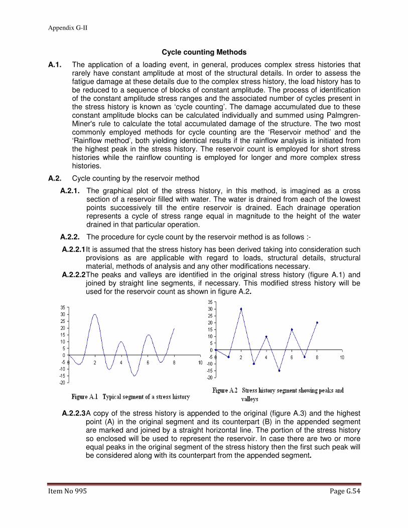
Appendix G-II
Item No 995 Page G.54
Cycle counting Methods
A.1. The application of a loading event, in general, produces complex stress histories that rarely have constant amplitude at most of the structural details. In order to assess the fatigue damage at these details due to the complex stress history, the load history has to be reduced to a sequence of blocks of constant amplitude. The process of identification of the constant amplitude stress ranges and the associated number of cycles present in the stress history is known as ‘cycle counting’. The damage accumulated due to these constant amplitude blocks can be calculated individually and summed using Palmgren-Miner's rule to calculate the total accumulated damage of the structure. The two most commonly employed methods for cycle counting are the ‘Reservoir method’ and the ‘Rainflow method’, both yielding identical results if the rainflow analysis is initiated from the highest peak in the stress history. The reservoir count is employed for short stress histories while the rainflow counting is employed for longer and more complex stress histories.
A.2. Cycle counting by the reservoir method
A.2.1. The graphical plot of the stress history, in this method, is imagined as a cross section of a reservoir filled with water. The water is drained from each of the lowest points successively till the entire reservoir is drained. Each drainage operation represents a cycle of stress range equal in magnitude to the height of the water drained in that particular operation.
A.2.2. The procedure for cycle count by the reservoir method is as follows :-
A.2.2.1 It is assumed that the stress history has been derived taking into consideration such provisions as are applicable with regard to loads, structural details, structural material, methods of analysis and any other modifications necessary.
A.2.2.2 The peaks and valleys are identified in the original stress history (figure A.1) and joined by straight line segments, if necessary. This modified stress history will be used for the reservoir count as shown in figure A.2.
A.2.2.3 A copy of the stress history is appended to the original (figure A.3) and the highest point (A) in the original segment and its counterpart (B) in the appended segment are marked and joined by a straight horizontal line. The portion of the stress history so enclosed will be used to represent the reservoir. In case there are two or more equal peaks in the original segment of the stress history then the first such peak will be considered along with its counterpart from the appended segment.

Appendix G-II
Item No 995 Page G.55
A.2.2.4 The reservoir is drained successively from the lowest points (E, F, D and C taken in order as shown in figure A.4) which retain water till the entire reservoir is emptied. Each drainage operation corresponds to a cycle of stress range equal in magnitude to the height of the water drained in that particular operation i.e. one cycle of stress
range σA - σE when drainage is from trough E.
A.2.2.5 The stress ranges and their associated number of cycles are sorted according to the magnitude of the stress ranges for further processing using the Palmgren-Miner criteria.
A.2.3. Consider the following example :-
A stress history consists of the following stress variation
Time 1 2 3 4 5 6 7 8 9 10 11 12 13 14
Stress 28 -18 8 2 22 -6 20 8 20 -18 22 -4 26 12
A, O B C D E F G H I J K L M N
In order to conduct a reservoir count appending the first point, as it is the highest,
will suffice for the definition of the reservoir. A schematic diagram indicating the

Appendix G-II
Item No 995 Page G.56
extent of drainage from each trough is as shown in figure A.5. The points in the
stress history have been labeled from A to O for easy identification.
The results from the reservoir count can be tabulated as follows:-
Drainage from Trough Highest water level at Stress range
B A 46
J K 40
F G 26
L K 26
D C 6
H G 12
N M 14
The above may be arranged in order for further processing.
A.3. Cycle counting by the rainflow method
A.3.1. The rainflow counting technique is based on the visualization of flow of rain over a sequence of pagoda roofs and essentially counts half cycles. In order to effect the visualization the stress history is rotated such that the time axis is vertical with the origin located towards the top. Rainflow is assumed to begin from a peak or a trough and the distance it travels determines the magnitude of the stress range, each flow contributing a half cycle.
A.3.1. The procedure for rainflow count is as follows :-
(a) It is assumed that the stress history conforms to 2.2(a) and is modified in accordance with 2.2(b) so that the stress history is reduced to a sequence of peaks and troughs.
(b) The stress history may be modified in accordance with 2.2(c) so that it begins and ends with the highest peak (or the deepest trough).

Appendix G-II
Item No 995 Page G.57
(c) The stress history is rotated through 90o such that the origin of the time axis is located towards the top (figure A.6).
(d) A drop begins to flow (figure A.7) left from a peak (1-2) or right from a trough(1-3) onto subsequent roofs (3-4-6) unless the surface receiving the drop is formed by a peak which is more positive than the origin of the drop (1-2) for a left flow, or, a trough that is more negative for a right flow(4-5).
(e) The path of a drop cannot cross the path of a drop which has fallen from a higher roof (5-6).
(f) A drop ceases to flow when it reaches the end of the stress history record (1-3).
(g) The horizontal displacement of the drop from its origin to its final position measured in appropriate stress units represents a half cycle of the associated stress range.
A.3.1. Considering the same example as in 2.3 the rainflow patterns are as shown in figure A.8.

Appendix G-II
Item No 995 Page G.58
The results from the rainflow count can be tabulated as follows:-
Origin of flow Termination of flow Half cycle stress range
A B 46
B O 46
C D 6
D C 6
E J 40
F G 26
G F 26
H I 12
I H 12
J K 40
K L 26
L K 26
M N 14
N M 14

Appendix G-II
Item No 995 Page G.59
The half cycles in the above may be combined and subsequently arranged in order for
further processing. It may be noted that the results of the rainflow and the reservoir counting
are identical in this case.
A.3.1. Stress Histogram: If we divide stress range in units of 10, Stress histogram for the above cycles can be made as follows:-
Stress Range slab Mean Value of
Stress Range slab
No of Cycles
0-9.9 5 1
10-19.9 15 2
20-29.9 25 2
30-39.9 35 0
40-49.9 45 2
***********

84TH BRIDGE AND STRUCTURES STANDARDS COMMITTEE MEETING
Item No 1066/1006 Page 62
Item No. 1006/84th: Guidelines on Seismic Design of Railway Bridges.
Ref: Item No. 1006/79th/2010/CBS/Project Seismic/I&P
COMMITTEE’S OBSERVATIONS:
1. The adoption of new seismic design method requires corrections in several codes of Railways. Seismic provisions scattered in different codes will create confusion.
2. Provision of a single Seismic Code will avoid duplicity of codal provisions and will make revisions and updation much easier.
COMMITTEE’S RECOMMENDATIONS:
1. It is recommended to have a single Seismic Code for Railway Bridges. Necessary procedures shall be followed for issue of a new Code.
2. The RDSO Guidelines for Seismic Design of Railway Bridges can be converted into a Seismic Code for Railway Bridges.
3. Necessary Correction Slips shall be issued for all the existing Codes replacing all the Seismic related clauses with a reference to Seismic Code for Railway Bridges.
RAILWAY BOARD ORDERS:
A New Seismic Code For Railways Bridges shall be prepared by the RDSO based upon “RDSO Guidelines on Seismic Design of Railway Bridges” synchronizing with all the existing codes. Necessary correction slips shall be proposed in existing codes and manuals replacing all the relevant Para with a reference to the proposed Seismic Code.
PRESENT STATUS:
The current Seismic provisions of Bridge rules have now become obsolete and needs to be replaced with latest provisions of IS codes, which are based on the current International Seismic design philosophy and practices.
After 83rd BSC meeting, it was decided that a New “Seismic Code for Railways Bridges” shall be prepared by the RDSO based upon “RDSO Guidelines on Seismic Design of Railway Bridges” synchronising with all the existing codes. Necessary correction slips shall be proposed in existing codes and manuals replacing all the relevant Para with a reference to the proposed Seismic Code.
However, IS-1893 (Part 3) dealing with Seismic Design of Highway and Railway Bridges has now been published by the BIS. But this IS code cannot be adopted by Railways in Toto because we want some of the design parameters changed for Railway loadings. The IS 1893 (part3) stipulates the Live load combination factor to be 30% instead of 50% adopted by us. The response reduction factors for Bearings and foundations are also very low and at variance with what we have adopted for Railways. Apart from these constant factors, IS code 1893

84TH BRIDGE AND STRUCTURES STANDARDS COMMITTEE MEETING
Item No 1066/1006 Page 63
(part 3) and the RDSO’s Seismic Guidelines for Railway Bridges are having exactly the same provisions.
To avoid duplicity or confusions, it is now proposed that we adopt the IS1893 (part 3) with small modifications in R values and Live Load factor as Railways Seismic Code. Hence a Draft Seismic Code for Railway Bridges has been prepared based upon IS-1893 (part 3) with only a small change in R value and Live Load factor. The provisions of ductile detailing as given in the Appendix A is also the same as in IS 1893. The Railways Seismic Code for all practical purpose shall be same as IS 1893-(Part 3) with all the references to related IS-codes such as IS-1893 (part-1) for Zone map and IS code 13920-1993 for ductile detailing etc remaining intact.
In due course of time the IS code 1893 (part 3) may get revised based upon Railway’s Seismic code and then in that case there will be no conflict in the railways and IS codes.
*************

84TH BRIDGE AND STRUCTURES STANDARDS COMMITTEE MEETING
Item No 1024 Page 64
Item No. 1024/84th: Inclusion of provision of HSFG Bolt in IRS Steel
Bridge Code.
Ref: Item No. 1024/80th/2011/ CBS/DFP
COMMITTEE’S OBSERVATIONS:
1. HSFG bolts are advantageous as compared to rivets and shall be used.
2. The proper provision of HSFG bolts requires care on part of personnel carrying out/ inspecting the work.
3. RDSO submitted that HSFG bolts are as per IS codes and need not have separate vendor List. However it was discussed that HSFG bolts are a new introduction in system and more care in quality is required.
COMMITTEE’S RECOMMENDATIONS:
1. RDSO shall propose a cut off date for making HSFG bolts mandatory for all steel construction.
2. RDSO shall prepare vendor list for this item.
3. Training of field engineers shall be arranged by RDSO.
RAILWAY BOARD ORDERS:
1. The instruction have already been issued vide Board’s letter No. 2014/CE-III/BR/Bridge Policy dated 31.08.2015 for using drawings with HSFG bolt works for all future bridge works.
2. RDSO to issue list of known sources for HSFG bolts within two months time.
3. RDSO shall integrate training on HSFG bolts in the training programmes regularly organized for steel fabrication.
PRESENT STATUS:
1. HSFG bolts are being taught regularly at IRICEN and has been included in RDSO’s training programs.
2. RDSO has issued BS:111 Revision 5 and QAP has been incorporated in the same for ensuring quality in field. RDSO is associating with IRICEN for training in HSFG Bolts and has included these in fabrication training.
3. List of known sources is not a standard procedure at RDSO. Few items for which such lists have been prepared give rise to complaints as there is no procedure for updating the list and vendors left out of this list keep on complaining. If proper procedure is not followed, improper Vendors get included in “list of known sources.”
4. High Strength Friction Grip (HSFG) bolts were approved for use on railway bridges in January 2014. These bolts have been used for ROBs for a

84TH BRIDGE AND STRUCTURES STANDARDS COMMITTEE MEETING
Item No 1024 Page 65
couple of years prior to that. RDSO has issued guidance to field units through report no BS-111, which has been regularly updated to reflect the latest knowledge in this respect.
5. There are few reports of problems due to use of HSFG bolts and most of the problems referred are due to use of non-standard procedure/equipment for tightening and due to non-usage of Direct Tension Indicator (DTI) washers. The performance of HSFG bolts depends on proper tightening of bolts on properly prepared surface.
6. 3.0 The surface preparation for new applications has been specified as “Metallising without overcoating”. The specifications for metallising are as per IRS B1, para 39.2.1. Checking the thickness of metallising is a simple procedure using elcometer and the quality of surface preparation ca be easily ensured. Some old tenders did not have metallising provisions but newer tenders are all having this provision.
7. 4.0 Therefore, proper tightening of bolts is the only variable that needs proper care in field. The procedure given in IRS Steel Bridge code is simple and can ensure proper tightening if the field officials take care in inspections. But the quality still depends on the diligence of the field officials.
8. 5.0 There is another class of bolts whose action is similar to HSFG bolts but the quality control is easier. These bolts, called lock bolts, are provided on slightly different principle than HSFG bolts. The HSFG bolts require proper torque to be given to the bolt so that proper axial tension is induced in the same, whereas the lock bolts are pulled axially to directly give the requisite tension in the shank of the bolt before the collar is pressed to complete the bolt installation. Certain bolts have an additional feature wherein the extended leg of bolt is broken by twisting off the same.
9. Advantages of Lock bolts:
a. The axial load in bolt shank is directly given, so the chances of axial load being correct are higher. Unlike HSFG bolts, these bolts are not dependent on the condition of surface of threads to determine the amount of torque that is transmitted as axial force in bolt.
b. The installation is faster than HSFG bolts as reliable single stage installation is possible.
c. There are certain bolts in which the indication of desired axial load being given to the bolt is provided in bolt itself. These bolts will not require DTI washers to be used.
d. With close fitting bolts, these can be used as a replacement of rivets in repair applications. Since the rivets have been phased out in new construction, it is likely that, in few years, the riveting equipment and skilled persons will not be available at all for carrying out the repair works. This was also a recommendation no 2(iv) of committee of CBEs for review of maintenance practices for bridges.

84TH BRIDGE AND STRUCTURES STANDARDS COMMITTEE MEETING
Item No 1024 Page 66
e. These bolts can be one-to-one substitute for HSFG bolts for appropriate property class.
f. These bolts are temper-proof and don’t require tack welding or locking of threads as currently specified in railway codes.
g. These bolts are covered in British standard BS 7805 Part 2:1997.
h. The lock bolts are already in use in wagons for underframe where welding is not desirable. Specifications have been issued vide WD-11036-S-01 and WD-11036-S-02 for “Technical requirements and performance parameters of lock bolts and collars used in wagons”.
10. Disadvantages of Lock bolts:
a. Two-stage tightening is not possible with lock bolts. For joints with thicker plates, two stage tightening to ensure that the plates are in close contact is essentially required, as the joint will not work on friction grip effect. To overcome this shortcoming, ordinary bolts can be used for first stage tightening and then replaced by lock bolts in second stage. The proper contact between plates can be ensured after the first stage.
b. There are some apprehensions about malfunctioning of the equipment to be used for installing the lock bolts. For the same, these bolts shall be required to be periodically checked for proper axial load using DTI washers.
c. Special proprietary equipment are required to tighten the bolts. This equipment may be electrically operated or hydraulic and are generally operated by the bolt manufacturers themselves. This can lead to reliance on the manufacturer to complete the projects on time. This problem will be acute for projects where the number of bolts is lesser.
d. Some bolts with twist-off feature have lots of wastage. This makes these bolts slightly costlier than normal HSFG bolts in capital cost even though the labour requirement is lesser.
11. The committee may deliberate and decide on the following issues:
1. Whether any standard list of vendors shall be prepared for HSFG bolts/nuts and washers which are to be supplied as per IS codes.
2. Whether RDSO shall prepare specifications for lock bolts for use on Indian Railways.
*************

84TH BRIDGE AND STRUCTURES STANDARDS COMMITTEE MEETING
Item No 1025 Page 67
Item No. 1025/84th: Standard Drawings for FOB’s.
Ref: Item No. 1025/80th/2011/ CBS/DFOB
COMMITTEE’S OBSERVATIONS:
New Designs with lighter structures must be adopted as has been done in Western & Central Railways. The new design shall be lighter, durable and easily maintainable. Support should be single column base on Platform. Subways to be preferred instead of very high FOBs. Maintenance of FOBs is a big problem today.
COMMITTEE’S RECOMMENDATIONS:
1. RDSO to explore new forms of FOBs with aesthetics and addressing maintenance/ construction aspects.
2. Single central column shall be given and provision of lift.
3. Ramp Design may also be examined.
4. Suggestions from Railways may be sent to RDSO.
RAILWAY BOARD ORDERS:
RDSO to explore new forms of FOB’s keeping the requirements of aesthetics and ease in maintenance.
PRESENT STATUS:
The design unit at RDSO is presently engaged in the design and drawing of Long Span Open web girders and High priority Bow String Arch ROB’s.
After completing high priority designs the design of new FOB’s will be taken up.
*************

84TH BRIDGE AND STRUCTURES STANDARDS COMMITTEE MEETING
Item No 1038 Page 68
Item No. 1038/8th: Yardsticks for Bridge Organisation.
Ref: Item No. 1038/81st/2012/ CBS/Admn.
COMMITTEE’S OBSERVATIONS:
This is a very important item affecting creation of posts and bridge maintenance in field. The work of committee needs to be expedited.
COMMITTEE’S RECOMMENDATIONS:
The committee shall complete its work within next three months and submit report before 01-09-2015.
RAILWAY BOARD ORDERS:
Committee to submit report by 31-10-2015.Item to be dropped from BSC.
PRESENT STATUS:
Further Railway Board vide letter No. 2015/CE-III/BR/ Yardsticks for Bridges/4 dt.11.12.15 advised committee that lot of new bridges/ tunnels on new lines/doubling etc. are under construction in hilly regions/across large rivers necessitating construction of tall piers and massive superstructures such as Bogibeel Bridge, Ganga Bridge in Patna and Munger, Chenab Bridge etc.Committee shall take up in to account efforts required for inspection and maintenance of bridge piers which has increased exponentially with increase in height of piers and a proper assessment of workload is to be done for such bridges for field supervisors viz. BRIs, IOWs and PWIs.
Committee has taken up this task also along with terms and references to the committee made vide Railway Board’s letter No. 2015/CE-III/BR/ Yardsticks for Bridges/4 dt.11.12.15.Last meeting was held at IRICEN, Pune on12.02.2016.Performa for collection of details have been circulated to all CBEs with a view to obtain details of the existing system and practices. Committee has planned to visit Chenab, Bogibeel and Ganga Bridge site Patna and Munger to assess the workload.
Efforts are being made to submit the report shortly.
Committee may kindly deliberate further.
*************

84TH BRIDGE AND STRUCTURES STANDARDS COMMITTEE MEETING
Item No 1040 Page 69
Item No. 1040/84th: Technical guidelines for Box Pushing technique.
Ref: Item No. 1040/82nd/2014/ CBS/DBC
COMMITTEE’S OBSERVATIONS:
1. RDSO has prepared draft guidelines based on references received from some zonal railways.
2. This need to be further studied. Railways shall forward details of difficulties/problems faced by them so that these cases can be included in the guidelines before issue.
COMMITTEE’S RECOMMENDATIONS:
Detailed study is needed, especially in regard to problems/ difficulties faced by Railways. Railways to send details in this regard to RDSO.
Item to be closed after issue of guidelines or instructions in this regard.
RAILWAY BOARD ORDERS:
Instructions have already been issued by Railway Board vide Policy letter No. 2014/CEIII/BR/Bridge Policy dated 29.05.2015. Item to be closed.
PRESENT STATUS:
Railway Board vide letter No. 2014/CEIII/BR/Bridge Policy dated 29.05.2015 advised Zonal Railways that Box pushing should not be resorted as this led to unsafe condition. It was also advised that in exceptional circumstances Box Pushing Technique should be adopted that too, with the personal approval of PCE/CAO/C concerned.
Railway Board has further advised vide letter No. 2016/CEIII/BR/Bridge Policy dated 25.10.2016 that this item needs to be discussed in BSC.
Guidelines for Box Pushing Technique were compiled at RDSO and submitted to Railway Board vide RDSO letter No. CBS/Box Pushing dated 18.07.2014. A copy of Draft Guidelines for Box Pushing Technique was also circulated to Zonal railways for comments vide letter No. CBS/Box Pushing dated 04.03.2015.
BSC may please deliberate upon the item.
*************

84TH BRIDGE AND STRUCTURES STANDARDS COMMITTEE MEETING
Item No 1042 Page 70
Item No. 1042/84th: Periodicity of changing of oil in oil bath for roller bearing.
Ref: Item No. 1042/82nd/2014/ CBS/ Bearing
COMMITTEE’S OBSERVATIONS:
This item may be closed.
COMMITTEE’S RECOMMENDATIONS:
Item may be closed.
RAILWAY BOARD ORDERS:
RDSO shall study how the periodicity of change of oil bath has been decided and the item may be presented in next BSC.
PRESENT STATUS:
This item was deliberated in the 82nd BSC and the committee observed that Oil in the Oil bath degrade after prolonged used and may not remain usable after cleaning. Hence oil replacement frequency must be decided to maintain the quality. After due deliberations and discussions the committee decided that the oil in the oil bath bearing must be replaced completely after every 5 year.
Railway Board accepted the above recommendations of 82nd BSC and asked the RDSO to issue the necessary correction slips in Bridge Manual.
Accordingly, advance correction Slip number 32 to IRBM dated 12-03-2015 have been issued and uploaded on the web site. The Para 222 2(f) has been replaced and it says;
“In the case of roller bearing with oil bath, dust covers should invariably be provided to keep the oil free from dirt. Whenever oil bath bearings are provided, inspection of the bearing, after removal of the casing to the extent necessary, should be carried out at least once in 5 years. Checking of oil level, draining out as necessary to detect and remove any water collected at the bottom and replenishing the oil, should be done annually. The Oil in Oil bath Bearing must be changed completely once in every 5 years.”
Now the Railway Board has directed that the basis on which the frequency of 5 years was decided be discussed again.
The basis on which the frequency of Oil change was decided are as follows:-
1. Existing and prevalent RDSO guidelines in the form of BS-102 clearly stipulates (in Para 3.3-page 4) that Oil in the Oil Bath must be changed completely every 5 years. Therefore, the old guidelines already existed for 5 year replacement frequency.
2. The service life of oil in a bearing system depends upon several factors such as type of oil, pressure and temperature, dirt and water

84TH BRIDGE AND STRUCTURES STANDARDS COMMITTEE MEETING
Item No 1042 Page 71
contamination etc. The service life of Oil will also depend on Span of the Bridge and Traffic. Water may remain well mixed in the oil through emulsification and still appear perfectly clean oil. However, water contamination acts as catalyst for oil degradation in the form of resin and sludge formation. The Oil film breaks down under heavy pressure if water gets mixed in the oil through emulsification. Even the best type of oil will have a finite and limited service life under such high pressure surface sliding asis the case in large bridge bearings.
3. There are no clearly established OIL cleanliness standards for Railway bridge bearings. Therefore, rejection or acceptance of the Oil after a certain years of service life based upon chemical& filtration analysis is a complicated issue.
4. There are NO official records of OIL testing of existing Oil bath bearings and no one can say for sure that the OIL contamination level is within acceptable range or not. Even Oil filtration standards have not been defined in any of our manuals for Bridge Bearings.
5. The Cost of replacement of Oil for Bridge Bearings are quite insignificant even if it is thrown away after 5 years as a waste product. However, the Oil need not be thrown away as a waste product and its recycling elsewhere will reduce the cost of wastage even further. The OIL after filtration can be very well used in other equipment’s and machines such as small and large track machines, mobile cranes and Vehicles etc.
6. Once the oil replacements starts, we can get it tested and create a record which may help us in arriving to any revised frequency of oil replacement in future.
*************

84TH BRIDGE AND STRUCTURES STANDARDS COMMITTEE MEETING
Item No 1045 Page 72
Item No. 1045/84th: Introduction of Higher spans and skew angles in
ROB drawings.
Ref: Item No. 1045/82nd/2014/ CBS/DRO/Skew
COMMITTEE’S OBSERVATIONS:
1. There is wide spread requirement of ROBs at higher skew angles. However the methods suggested by RDSO shall allow reduction of skew angles below 20 degree in most of the cases which are covered by RDSO drawings. For exceptional cases local designs may be used.
2. For 6 line highways, Bow string girders shall have 3 lanes.
COMMITTEE’S RECOMMENDATIONS:
1. RDSO shall issue instructions for restricting skew angles to 20 degree as far as possible.
2. Bow string girders shall be designed for 3 lane width.
3. The item may be closed.
RAILWAY BOARD ORDERS:
1. RDSO to issue instructions for restricting Skew angles to 20 deg as far as possible.
2. RDSO to design Bow String Arch Girders for 3-Lane Bridges.
3. Item to be closed.
PRESENT STATUS:
RDSO has incorporated the instructions regarding skew angle in report no BS-112.
The revised RDSO drawings for revised lane width configurations for NHAI have been designed and GAD/structural details of main girder drawings have already been issued. Other drawings are being prepared and will be issued shortly.
RDSO is going to develop 3 Lane Bow String Arch Girder with new IRC lane width and loading. The Drawings are expected to be ready by June 2017.
*************

84TH BRIDGE AND STRUCTURES STANDARDS COMMITTEE MEETING
Item No 1047 Page 73
Item No. 1047/84th: Formulae for the estimation of scour depth at
bridge piers.
Ref: Item No. 1047/82nd/2014/ RBF/BSC/82
COMMITTEE’S OBSERVATIONS:
Feedback received from CR & SWR only. The details from other railways have not been received. Validation therefore could not be done of the new formula for scour estimation.
SER, ECR and ER have mentioned that they will provide details of scour observed in last 50-100 years for at least 10 bridges each.
RDSO will compare scour estimation for these bridges to validate the formulae.
COMMITTEE’S RECOMMENDATIONS:
SER, ECR and ER to provide scour observed data for 10 bridges each.
RDSO to validate the formula and results be advised to Railways.
Item be closed.
RAILWAY BOARD ORDERS:
1. RDSO to validate the formula and propose A&C slip.
2. Item to be closed after issue of A&C slip.
PRESENT STATUS:
1. SER, ECR and ER were requested to submit the requisite data to RDSO vide letter no. RBF/BSC/82 dated 22.09.2015.
2. Reminders to ECR &ER have been sent vide letter nos. RBF/BSC/82 dated 12.07.16 and 15.09.2016. The required data is still awaited from both Railways.
3. SER has submitted the data for 10 bridges to RDSO vide their letter dated 03.11.2015. After due analysis the data submitted by SER has been found incomplete. Accordingly SER has been informed.
4. The validation of the Melville formula will be done after getting the complete data from three Railways.
*************

84TH BRIDGE AND STRUCTURES STANDARDS COMMITTEE MEETING
Item No 1050 Page 74
Item No. 1050/84th: Working of BCM through ballasted deck.
Ref: Item No. 1050/82nd/2014/ CBS/BCM Machine
COMMITTEE’S OBSERVATIONS:
Railway Board Order are awaited on the committee’s report.
Relaxation in para 8 (iii) (a) & (c) of chapter-I of IRSOD in accordance with provision of para 11 A (v) & (vi) of chapter-II of IRSOD.
COMMITTEE’S RECOMMENDATIONS:
Action need to be taken based on Railway Board Orders on committee’s (nominated by Railway Board) recommendations.
RAILWAY BOARD ORDERS:
Committee’s report under consideration. Board’s orders on Committee’s recommendations will be communicated.
PRESENT STATUS:
Committee’s report under consideration. Board’s order on Committee recommendations is awaited.
*************

84TH BRIDGE AND STRUCTURES STANDARDS COMMITTEE MEETING
Item No 1053 Page 75
Item No. 1053/84th: Buoyancy Effect for Design of Foundation and
Substructures.
Ref: Item No. 1053/83rd/2015/CBS/PSBC
COMMITTEE’S OBSERVATIONS:
Historical background for present provisions in IRS Sub-Structures and Foundations Code related to buoyancy effects for design of structures/ foundation were discussed. There is need to modify the present provision to further clarify them.
COMMITTEE’S RECOMMENDATIONS:
1. A&C Slip to Sub-Structures and Foundations Code to modify para 5.10 buoyancy effect be proposed by RDSO.
2. The para numbers need not be changed.
3. Item to be closed after issue of A&C Slip.
RAILWAY BOARD ORDERS:
Orders will be issued separately
PRESENT STATUS:
Vide letter No. CBS/PSBC dated 02.09.2014 & 10.06.2015, A&C Slip was submitted to Railway Board for approval. Railway Board, vide its letter no 2014/CE-III/BR/BSC/83/Seminar dated 07.10.2016 has advised that this issue to be addressed by the committee constituted for revising the IRS Sub-structure and Foundation code. The committee’s report is to be finalized by 31.12.2016.
*************

84TH BRIDGE AND STRUCTURES STANDARDS COMMITTEE MEETING
Item No 1054 Page 76
Item No. 1054/84th: Standard Inspection Arrangement for Bridges.
Ref: Item No. 1054/83rd/2015/CBS/DOW
COMMITTEE’S OBSERVATIONS:
1. Inspection arrangements are very important for proper inspections.
2. These arrangements shall not cause corrosion/damage to existing structures.
3. The inspection arrangements shall be incorporated in RDSOs standard drawings.
4. Lots of bridges already have inspection arrangements which can be referred standardizing.
COMMITTEE’S RECOMMENDATIONS:
1. BS report 113 has been issued by RDSO for planning of inspection arrangements.
2. Zonal railways shall share drawings/designs and photographs of inspection arrangement already provided in field.
3. RDSO shall examine different materials/methods that can be used to minimize corrosion in girders. The inspection arrangements shall be planned so as to cause least problems in steel/ concrete.
4. RDSO shall incorporate inspection arrangements in standard drawings.
RAILWAY BOARD ORDERS:
1. Provision of inspection arrangements is mandatory for all new bridges to be constructed vide Railway Board letter no 2014/CE-III/BR/Bridge Policy dated 09.10.2014.
2. Detailed inspection arrangements to be incorporated in the standard drawings by RDSO latest by 31.10.2015.
PRESENT STATUS:
1. No Zonal Railway has sent any photograph/arrangement already provided in field. All railways are requested once again to give the details of inspection arrangement provided on their jurisdictions and also give their opinion about BS-113 so that the same can be improved and the inspection arrangement drawings can be incorporated in the RDSO’s standard drawings.
2. Inspection Arrangement for Bearings: RDSO has issued inspection arrangement for bearings at piers as drawing no CBS-0016 on 27.03.2001.

84TH BRIDGE AND STRUCTURES STANDARDS COMMITTEE MEETING
Item No 1054 Page 77
3. Inspection Arrangement for Bearings and Plate/ Composite girders: RDSO has recently issued drawing No. CBS 0044 for inspection arrangement for standard plate and composite girder to RDSO drawings.
4. Inspection Arrangement for Open Web girders:
a. All the new drawings being developed by RDSO for long span Open Web girder are being provided with inspection footpaths. However, in the absence of any input by Railways, nothing could be decided on preferred methods of attachment of inspection arrangements on existing bridges.
b. The inspection arrangements attached with clamping arrangements only may become bulky and ugly looking. Such clamping arrangements are also likely to create corrosion in the clamping locations. It is preferred to have several cleats welded in appropriate locations to support the inspection ladders, pathways, platforms and railings. No structural weakness is introduced if welding of cleats is done on the existing structure at appropriate locations (such as web of a girder) with proper care and planning. We may decide to drill holes in the web of girders to fix the support angles for inspection frames instead of welding.
c. The Scope and number of Inspection arrangements cannot be standardized by RDSO for open web girders. It is recommended that modern and advance inspection tools such as Quadcopter/ Drone Camera be hired for important OWG bridge inspections, which are now cheaply and abundantly available in all metros. Then based upon specific requirements special repair or inspection arrangements may be installed on a temporary basis only. Further, the material to be used to erect such a temporary inspection arrangement may be built using light weight Aluminums Ladders or even composite materials. The material for inspection arrangements may also be not standardized. Therefore the BS report may be used as guideline for erection of such arrangements.
5. Inspection Arrangement for Concrete Girders:
a. Brief History-
Following minimum clearance to be ensured for proper inspection of prestressed structures as stipulated vide A&C Slip to IRS CBC, Dated 04.09.2006:
• Minimum vertical clearance inside PSC Box Girder shall be 900mm.
• Minimum gap between ballast wall and the girder shall be 600mm.
• Minimum gap between ends of the girders at piers shall be 1200mm.

84TH BRIDGE AND STRUCTURES STANDARDS COMMITTEE MEETING
Item No 1054 Page 78
• Size of opening in the diaphragms of PSC box girder shall be 600mm x 900mm (width x Height)
b. Various Inspection Arrangements for different types of bridges have been issued in BS-113 (Guidelines for Providing Arrangements for Bridge Inspection) in November 2014. For inaccessible parts, the arrangements for their inspection as per BS-113 are as below:-
• By temporarily hanging the platforms around the inspecting area of the girder.
• Vehicle mounted mechanical inspection Platform running on track, which will run in block.
• Vehicle mounted mechanical inspection Platform on river bed or floating on river.
• Permanent Inspection arrangement as in 6.3 of BS-113.
c. RDSO Remarks:
• The parts or portion of a PSC girder near the pier/abutment can be inspected visually.
• However, inaccessible parts may be provided with the following arrangements:
- Fixed arrangement on piers.
- Movable portable type trolley.
- High resolution camera (static or fitted on Unmanned Ariel Vehicle (UAV)/Drone).
- Also, if permanent fixed Inspection arrangement is to be supported from PSC Girder itself then PSC Girder will have to be designed/ checked for the same.
• Further, Railways may advise the arrangement for inspection presently being used by them so that standardization of the same can be examined.
6. Inspection Arrangement for sub-structure: BS-113 mentions either inspection vehicle or rungs provided on the piers/abutments for inspection. There was an idea about lift for tall piers (>40m). The practical solution is, however, not yet in sight. The Zonal Railways may give arrangements provided, if any, or give their opinion about possible solutions.
7. The committee may deliberate further.
*************

84TH BRIDGE AND STRUCTURES STANDARDS COMMITTEE MEETING
Item No 1055 Page 79
Item No. 1055/84th: Revision of Standard list of tools and equipment
for inspection of bridges.
Ref: Item No. 1055/83rd/2015/CBS/IRBM
COMMITTEE’S OBSERVATIONS:
RDSO shall take suggestions from Zonal Railways and prepare a comprehensive list of tools/equipments for inspection.
COMMITTEE’S RECOMMENDATIONS:
Correction Slip shall be proposed by RDSO.
RAILWAY BOARD ORDERS:
A committee of CBEs has been nominated by Railway Board to make a comprehensive list of tools and equipments for inspection of bridges. RDSO to propose correction slip(s) taking into account recommendations of this committee. The item stands closed after issue of correction slip(s).
PRESENT STATUS:
Final Railway Board Orders on the report of committee of CBEs awaited. The A&C Slip will be proposed after the orders are received.
*************

84TH BRIDGE AND STRUCTURES STANDARDS COMMITTEE MEETING
Item No 1057 Page 80
Item No. 1057/84th: Percentage of passive earth pressure to be taken in design and analysis of well foundation.
Ref: Item No. 1057/83rd/2015/CBS/PSBC
COMMITTEE’S OBSERVATIONS:
Historical background of present provisions in IRS Sub-Structures and Foundations Code (Para 6.9.3) was discussed. It is observed that while issuing A&C Slip some error was incorporated and it gives contradictory instructions (in first part and second part of the para).
COMMITTEE’S RECOMMENDATIONS:
A&C Slip be proposed by RDSO to clarify the provisions. Item may be closed after issue of A&C.
RAILWAY BOARD ORDERS:
Orders will be issued separately.
PRESENT STATUS:
Vide letter No. CBS/PSBC dated 16.06.2015, A&C Slip submitted to Railway Board for approval. Railway Board, vide its letter no 2014/CE-III/BR/BSC/83/Seminar dated 07.10.2016 has advised that this issue to be addressed by the committee constituted for revising the IRS Sub-structure and Foundation code. The committee’s report is to be finalized by 31.12.2016.
*************

84TH BRIDGE AND STRUCTURES STANDARDS COMMITTEE MEETING
Item No 1059 Page 81
Item No. 1059/84th: Provision of Shrinkage and Temperature reinforcement in Concrete Structures.
Ref: Item No. 1059/83rd/2015/CBS/DBC
COMMITTEE’S OBSERVATIONS:
The provisions in para 4.9 and 5.9.9 may be deleted. These are very stringent and otherwise covered by other provisions.
COMMITTEE’S RECOMMENDATIONS:
RDSO shall propose A&C slip to delete para 4.9 and 5.9.9 of IRS Concrete Bridge Code. Item be closed after issue of A&C slip.
RAILWAY BOARD ORDERS:
There is no requirement of discussion on standardization of Drawings in BSC.
PRESENT STATUS:
Draft A&C Slip No. 4 to IRS Concrete Bridge Code has been sent to Railway Board for approval vide letter No CBS/PSBC dated 11.06.15. Railway Board has again been requested for approval vide letter No. CBS/PSBC dated 22.09.15.
Approval of Railway Board is awaited.
*************