
Government of Niue 2018/LIOLAU PROJECT... · S1 S2 AREA CALCULATION METHODOLOGY Calculation...
15
Liolau Accommodation Project No: 1-42944.00 Government of Niue CONSENT & TENDER / 08.03.2017
Transcript of Government of Niue 2018/LIOLAU PROJECT... · S1 S2 AREA CALCULATION METHODOLOGY Calculation...

Liolau AccommodationProject No: 1-42944.00
Government of NiueCONSENT & TENDER / 08.03.2017

S1
S2
AREA CALCULATION METHODOLOGYCalculation methodology has been based on the 2010 BOMA standard of measurement foroffice spaces and is summarised as follows:
GROSS FLOOR AREA:Line of external face of exterior walls and centreline of inter-tenancy walls
RENTABLE FLOOR AREA:Line of internal face of exterior walls and centreline of inter-tenancy walls
AREA SCHEDULE:Item Area Coverage %Overall Site Area = XXXm²
Gross Building Area = XXXm² XX%
Overall Building Footprint Area = XXXm² XX%(Roof overhang)
Hard Landscaping = XXXm² XX%
Soft Landscaping = XXXm² XX%
GENERAL NOTES:
The Architectural drawings shall be read in conjunction with the associated specificationsand conditions of contract. The drawings shall also be read in conjunction with thestructural, services, civil and other project documents. Any discrepancies in thearchitectural drawings or between and consultant documents shall be referred to theArchitect for resolution
Verify all dimensions with structural, services, civil and other project documents prior toconstruction commencing. Refer all discrepancies to the Architect for resolution
Substitution for or amendment of specified details or material shall not be carried out withoutprior approval of the Architect
All work shall comply with the NZBC, all relevant Local Authority bylaws, NZS 3604, and allrelevant standards
All work to be carried out in accordance with drawings and specification provided
All work to be undertaken to be best trade practice for each respective trade. Anysubstandard work or building material defects shall be the Contractors responsibility toremove, repair or replace at no extra cost to the contract
The Contractor shall ensure that all rubbish is removed from site during and at the end ofthe contract works
The Contractor shall provide the appropriate temporary fencing, hoarding, guardrails andsignage as necessary to protect the public and others during the contract works and to meetthe requirements of the Local and Territorial Authorities
All timber shall be H1.2 treated graded SG-8 unless stated otherwise
Refer to the Structural Engineer's drawings and specification for steelwork and timberframing sizes
Refer to the Service Consultants drawings and specification for all services and equipmentrequirements
ACCESSIBILITY LEGEND
Indicates accessible route1200mm wide minimum
Provide and install accessible entrance sign, DeneefeDNM3 120x120mm, or equal. Sign to be installed1400-1700mm above the floor
Provide and install accessible toilet sign, Lockwood LWBRS0702 (160x160mm) or equal. Sign to be installed1400-1700mm above the floor
Signs to have lettering and symbols in clear contrast withthe background. The size, type, and layout of lettering onsigns shall be clear and legible (recommended fonts areArial, Times New Roman or Helvetica Medium).
Accessible Requirements :Light switches to align horizontally with the door handle
Socket outlets to be located 500-1200mm above the floorand a minimum of 500mm from any corner
Electronic access units for swipe cards, key pads, dooractivating buttons, etc. shall have a level, stable, firm, slipresistant floor surface of 1200 x 1200mm minimum adjacentto the access unit; be installed at 900 - 1200mm above thefinished floor level (1000mm is optimal); be installed no lessthan 500mm from an internal corner; be installed adjacentto the door under control; and have sufficient time delay forthe door to be opened before the locking system re-activates
All fittings within the accessible toilets and showers are tocomply with NZS:4121 Access & Mobility
Refer to specification for fitting and fixture details
COMMON ABBREVIATIONS
AP Access PanelAFFL Above Finished Floor LevelAS Australian Standard
BCA Building Consent AuthorityB/S Both Sides
Code Building CodeCL Centre Linecrs CentresCOS Check (Confirm) on SiteCHS Circular Hollow SectionCB Coach BoltCS Coach ScrewConc Concretecj Control JointCGI Corrugated IronCUPDCupboard
DPC Damp Proof CourseDPM Damp Proof MembraneDia DiameterDim DimensionDHS Dimond Hi-Span (Metal Purlin)DB Distribution BoardDg Double GlazingDP DownpipeDwg DrawingDW Dishwasher
ej Expansion Jointeq EqualEa Equal AngleEXT Extingulisher (Fire)
FA From AboveFHR Fire Hose Reelfg Fixed GlazingFCL Finished Ceiling LevelFGL Finished Ground LevelFin FinishedFWG Floor Waste GullyFFL Finished Floor Level
FRR Fire Resistance Rating
GT Gully TrapGalv. Galvanised
Horz HorizontalHG Hot Dipped GalvanisedHT Hose TapHWC Hot Water Cylinder
ID Inside DiameterIL Invert LevelIO Inspection Opening
kW Kilowatt
Max MaximumMS Mild Steelmm MillimetreMin MinimumMSB Main Switch Boardm² Square Meter
NZS New Zealand StandardNZBC New Zealand Building CodeNom NominalNTS Not To Scale
od Outside diameterO/A OverallO/F Over FlowO/H Overheadov Oven
PFC Parallel Flange Channelpc Precast PanelR RadiusRF Fridge (refridgerator)RL Reduced Levelref Referencerev RevisionRC Reinforced ConcreteRO Rough OpeningROW Right of WayRHS Rolled Hollow SectionRH RangehoodRWH Rain Water Head
Sk SinkSED Small End DiameterSH Showersim SimilarSP Soil PipeSpec SpecificationSHS Square Hollow SectionS.S Stainless SteelSSL Structural Surface LevelSTC Sound Transimition Class
TV Terminial VentT&G Tounge and GrooveTOW Top Of Wall
u/s UndersideUB Universal BeamUC Universal ColumnUR Urinal
Vert. Vertical
WHB Wash Hand BasinWC Water Closet (Toilet)
KEYNOTE LEGEND DRAWING TRANSMITTAL REGISTER
LOCATION PLAN
ROOM SCHEDULE
DISTRIBUTION
DayMonthYear
NO. OF COPIES ISSUED
ISSUE FORMAT:
REVISION
ISSUE STATUS:
APPROVED BY:
D DiskE Email
F FaxH Hard Copy
I InformationP PreliminaryA Approval
T TenderC ConstructionRAB As Record
DRAWING ANNOTATION
EXPRESSION OF LEVELSLevels are shown in terms of city datum (mean sea level = 0)Levels are as per AS1000 301 - 1985
Spot Level
Existing Level
Finished Floor Level
Finished Ceiling Level
Structural Surface Level
Relative Level shown onsections, elevations andsectional details
+
RL:
FFL:
FCL:
SSL:
RL:
WALL BRACING SYMBOL
GIB11.2 2.4
Type
Height
Length
KEYNOTE DESCRIPTION
4200.01 Profiled Vertical Metal Cladding
Specification Section
Generic Description
INTERIOR ELEVATION KEY
Wall Reference for InternalElevation & Schedule ofWork and finishes
A
B
C
D
Sequence Number
S
Lining Type (refer to drawing)
1
WALL FINISHES SYMBOL
Wall Function:S StandardW WetF FireA AcousticB Bracing
CEILING HEIGHT SYMBOL
Ceiling height abovestructural finished floorlevel
CH: 2400 AFL
NIUE ISLAND
Sheet No.Revision
Plot date:Original sheet size A1 (841x594)
Sheet Name
Client
Project No.
SCALE @ A1=
DRAWN
VERIFIED
Issue Date
DESIGN
Auckland StudioPO Box 5848, Auckland 1010New Zealand+64 9 355 9500
REVISIONS
NOTES
APPROVED
A R C H I T E C T U R A L
North
Project
DO NOT SCALE
THE CONTRACTOR SHALL VERIFY ALL DIMENSIONS ONSITE PRIOR TO COMMENCING ANY WORK
© COPYRIGHT OPUS ARCHITECTURE
CONSENT & TENDERNOT FOR CONSTRUCTION
G:\Projects\Niue\1-42944.00_Accommodation Block\A2 Concept Design\Drawings\Liolau_Accommodations_Niue(2015).rvt10/03/2017 9:45:36 AM
1 : 1
08.03.2017
C A002
INDEX SHEET
Government of Niue
Liolau AccommodationAvatele Village, Niue Island
1-42944.00
OPUS
OPUS
OPUS
OPUS
CODE GENERIC DESCRIPTION
REF. ROOM NAME OCCUPANT AREA (m²)
101-18 CONFERENCE ROOM 01 18.4 m²101-19 CONFERENCE ROOM 02 14.7 m²101-20 HALLWAY 4.6 m²101-21 CULTURAL HALL 83.9 m²101-22 DINING HALL 53.4 m²101-23 KITCHEN 19.8 m²101-24 MENS ABLUTION 27.5 m²101-25 STORE 6.7 m²101-26 BUILDING MAINTENANCE
STORE & TOILET6.7 m²
101-27 MENS DORM 46.2 m²101-28 STORE 8.8 m²101-29 MANAGER 6.9 m²101-30 WAITING AREA 5.2 m²101-31 DECK 49.3 m²101-32 HALLWAY 2.1 m²101-33 Room 247.3 m²101-34 STUDIO UNIT 04 34.1 m²101-35 STUDIO UNIT 03 34.0 m²101-36 STUDIO UNIT 02 34.0 m²101-37 STUDIO UNIT 01 34.2 m²101-38 WOMENS DORM 42.8 m²101-39 STORE 15.6 m²101-40 LAUNDRY 6.9 m²101-41 WOMENS ABLUTION 20.6 m²101-42 DECK 12.4 m²101-43 DECK 12.4 m²101-44 DECK 12.2 m²101-45 DECK 12.6 m²101-46 KITCHEN 10.1 m²
SHEET NO. SHEET NAMEA002 INDEX SHEET CA010 LOCATION PLAN CA011 SITE PLAN CA100 UPPER BLOCK GENERAL PLANS (STAGE 01) DA101 LOWER BLOCK GENERAL PLANS (STAGE 02) CA111 UPPER BLOCK R.C.P. & ROOF PLAN (STAGE 01) CA112 LOWER BLOCK R.C.P. & ROOF PLAN (STAGE 02) CA200 PROPOSED SITE ELEVATIONS CA201 UPPER BLOCK ELEVATIONS (STAGE 01) CA203 LOWER BLOCK ELEVATIONS (STAGE 02) CA300 UPPER BLOCK SECTIONS (STAGE 01) CA301 LOWER BLOCK SECTIONS (STAGE 02) CA400 GENERAL DETAILS (STAGE 01) BA700 SCHEDULES B
160616
1
E
P
Client:Project Manager:
Contractor:Quantity Surveyor:
Local Authority:
Structural Engineer:Civil Engineer:Hydraulic Engineer:Mechanical Engineer:Electrical Engineer:Fire Engineer:
AAAAAAAAAAAA
BBBBBBBBBBBB
200916
AA
B
211116
C
080317
CC
CD
C
CC
CC
CC
BB
A Preliminary Issue 17.06.2016B Consent & Tender 20.09.2016C Consent & Tender 08.03.2017

Avetele Beach
AveteleChurch
LiolauPrimarySchool
to Vaiea Village
toAlofi Town
Main Ring Road
WashawayCafe
Avetele Bay
Avetele Village
NIUE ISLAND
Sheet No.Revision
Plot date:Original sheet size A1 (841x594)
Sheet Name
Client
Project No.
SCALE @ A1=
DRAWN
VERIFIED
Issue Date
DESIGN
Auckland StudioPO Box 5848, Auckland 1010New Zealand+64 9 355 9500
REVISIONS
NOTES
APPROVED
A R C H I T E C T U R A L
North
Project
0 10mm 50 100
DO NOT SCALE
THE CONTRACTOR SHALL VERIFY ALL DIMENSIONS ONSITE PRIOR TO COMMENCING ANY WORK
© COPYRIGHT OPUS ARCHITECTURE
CONSENT & TENDERNOT FOR CONSTRUCTION
G:\Projects\Niue\1-42944.00_Accommodation Block\A2 Concept Design\Drawings\Liolau_Accommodations_Niue(2015).rvt10/03/2017 9:45:37 AM
Not to Scale
08.03.2017
C A010
LOCATION PLAN
Government of Niue
Liolau AccommodationAvatele Village, Niue Island
1-42944.00
OPUS
OPUS
OPUS
OPUS
Not to ScaleLOCATION PLAN1
A Preliminary Issue 17.06.2016B Consent & Tender 20.09.2016C Consent & Tender 08.03.2017
UP
A200 4
A200
3
A2001
A200
2
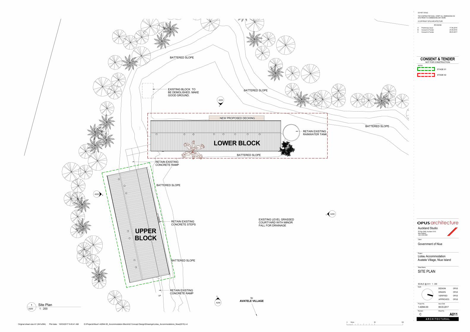
LOWER BLOCK
UPPERBLOCK
EXISTING LEVEL GRASSEDCOURTYARD WITH MINORFALL FOR DRAINAGE
BATTERED SLOPE
RETAIN EXISTINGCONCRETE RAMP
NEW PROPOSED DECKING
RETAIN EXISTINGCONCRETE STEPS
RETAIN EXISTINGRAINWATER TANK
EXISTING BLOCK TOBE DEMOLISHED. MAKEGOOD GROUND.
toAVATELE VILLAGE
BATTERED SLOPE
BATTERED SLOPE
RETAIN EXISTINGCONCRETE RAMP
BATTERED SLOPE
BATTERED SLOPE
BATTERED SLOPE
Sheet No.Revision
Plot date:Original sheet size A1 (841x594)
Sheet Name
Client
Project No.
SCALE @ A1=
DRAWN
VERIFIED
Issue Date
DESIGN
Auckland StudioPO Box 5848, Auckland 1010New Zealand+64 9 355 9500
REVISIONS
NOTES
APPROVED
A R C H I T E C T U R A L
North
Project
0 10mm 50 100
DO NOT SCALE
THE CONTRACTOR SHALL VERIFY ALL DIMENSIONS ONSITE PRIOR TO COMMENCING ANY WORK
© COPYRIGHT OPUS ARCHITECTURE
CONSENT & TENDERNOT FOR CONSTRUCTION
G:\Projects\Niue\1-42944.00_Accommodation Block\A2 Concept Design\Drawings\Liolau_Accommodations_Niue(2015).rvt10/03/2017 9:45:41 AM
1 : 200
08.03.2017
C A011
SITE PLAN
Government of Niue
Liolau AccommodationAvatele Village, Niue Island
1-42944.00
OPUS
OPUS
OPUS
OPUS
1 : 200A200
Site Plan1
A Preliminary Issue 17.06.2016B Consent & Tender 20.09.2016C Consent & Tender 08.03.2017
STAGE 01
STAGE 02

UP
UP
9 8 7 6 5 4 3 2 1
UP
UP
3A300
34 m²
STUDIO UNIT 04101-34
34 m²
STUDIO UNIT 03101-35
34 m²
STUDIO UNIT 02101-36
34 m²
STUDIO UNIT 01101-37
43 m²
WOMENS DORM101-38
16 m²
STORE101-39
21 m²
WOMENSABLUTION
101-417 m²
LAUNDRY101-40
12 m²
DECK101-42
12 m²
DECK101-43
12 m²
DECK101-44
13 m²
DECK101-45
U1 U2 U3 U4 U5 U6 U7 U8 U9 U10 U11 U12 U13 U14 U15
UA
UB
UC
UD
L2L3
A2011
A201
2
A201 4
A201
3
4A300
5A300
37551
2682 2682 2682 2682 2682 2682 2682 2682 2682 2682 2682 2682 2682 2682
1229
8
7050
2288
2960
whb
WM. Sk.
Sk.F Sh.
whbWC Sk.
FSh.
whbWC Sk.
F Sh.
whbWC Sk.
FSh.
whbWC
1A400
A7007
D31
D32
D33 D34 W11 W12 D35 D36 W13 W14 D37 D38 W15
W16
D39
D40D41
D42
W19W20
D43
D44D45
D46
W23W24W25
W10
W17W18W21W22
A700
11
300x300 Ceramic Tiles
Sealed Concrete
Vinyl with coving
FLOOR FINISHES
Sh. Sh. Sh.
Bench
W27
D50
D47D48D49
10 m²
KITCHEN101-46
D51
W26
U1 U2 U3 U4 U5 U6 U7 U8 U9 U10 U11 U12 U13 U14 U15
UA
UB
UC
UD
L2L3
WINDOW AND DOORS REMOVED
WINDOW REMOVED WINDOW REMOVED
1925
19751975
1925
5364 5364 5364 5364 5364 5364 5364
259 563 524 528 538 536 536 476
863
1106
1198
12141205108610251022106710841083
1037
886
554
339
1200
3200
173 3500 3500 3000 3000 3000 3000 3000 3000 3020 3050 3015 3090 178
37551
2682 2682 2682 2682 2682 2682 2682 2682 2682 2682 2682 2682 2682 2682
7050
2288
2960
1229
8
Sheet No.Revision
Plot date:Original sheet size A1 (841x594)
Sheet Name
Client
Project No.
SCALE @ A1=
DRAWN
VERIFIED
Issue Date
DESIGN
Auckland StudioPO Box 5848, Auckland 1010New Zealand+64 9 355 9500
REVISIONS
NOTES
APPROVED
A R C H I T E C T U R A L
North
Project
0 10mm 50 100
DO NOT SCALE
THE CONTRACTOR SHALL VERIFY ALL DIMENSIONS ONSITE PRIOR TO COMMENCING ANY WORK
© COPYRIGHT OPUS ARCHITECTURE
CONSENT & TENDERNOT FOR CONSTRUCTION
G:\Projects\Niue\1-42944.00_Accommodation Block\A2 Concept Design\Drawings\Liolau_Accommodations_Niue(2015).rvt10/03/2017 9:45:47 AM
1 : 100
08.03.2017
D A100
UPPER BLOCKGENERAL PLANS(STAGE 01)
Government of Niue
Liolau AccommodationAvatele Village, Niue Island
1-42944.00
OPUS
OPUS
OPUS
OPUS
1 : 100A200
Upper Block G.A. PLAN2
1 : 100A200
Upper Block Demolition Plan1
DEMOLITION NOTES
1. Remove all work shown hatched ordashed on the existing and demolitiondrawing
2. Visit the site and liaise with the Clientto determine the full extent of fittings tobe salvaged, stored or removed fromthe site for disposal. Check also thesite, the building or structural workbeing demolished and any contents forlikely hazard
3. Reinstate where any damage iscaused by this demolition to thoseparts of the existing building, otherbuildings and the remainder of the sitebeing retained
4. Where walls have been shown to bedemolished this shall include thecareful removal of any fixtures, fittingsand furnishings associated with thosewalls
5. Strip out all electrical wiring,conduits,light fittings, switches and powerpoints in removed walls and preparefor new electrical layout.
6. Unless specified otherwise removeand dispose all demolition items &materials off site at a suitable location.
7. Existing wall construction and extent isindicated to the best that availableknowledge allows. The contractor is toundertake a site survey to confirmscope prior tocommencing demolitionwork.
8. Ensure the structure above all items tobe removed is supported and secureprior to demolition.
9. Unless stated otherwise all makinggood shall match existing surfaces,profile, materials, etc & align withsame.
CONSTRUCTION NOTES
1. All non structural walls are to be timberframed and lined with 7mm thick ECOPLYF8 grade plywood conforming with nzs3614 - pre primed grade and wet areas tobe lined with JAMES HARDIE 6mm fibrecement cellulose sheet. The drawingsshall also be read in conjunction with thestructural and other project documents
2. Studio units floor finish to be 300mm x300mm non-slip ceramic tiles. Other wetareas to be finished with Armstrong 2mmslip-retardant sheet vinyl with welded joints.All other areas to be Sealed concrete.
3. All systems to be installed under strictmanufacturer recommendation unlessspecified.
C
A Preliminary Issue 17.06.2016B Consent & Tender 20.09.2016C Client Changes 21.11.2016D Consent & Tender 08.03.2017

UP
DW
UP
LA
A203
3
A2031
A203
2
A203 4 18 m²
CONFERENCEROOM 01
101-18
15 m²
CONFERENCEROOM 02
101-19
5 m²
HALLWAY101-20
84 m²
CULTURAL HALL101-21
53 m²
DINING HALL101-22
20 m²
KITCHEN101-23
27 m²
MENS ABLUTION101-24
7 m²
BUILDINGMAINTENANCE
STORE & TOILET101-26
7 m²
STORE101-25
46 m²
MENS DORM101-27
9 m²
STORE101-28
7 m²
MANAGER101-29
5 m²
WAITING AREA101-30
49 m²
DECK101-31
LB LC LD LE LF LG LH LI
UAUB
UC
L1
L2
L3
1A301
600
3900
OPE
NIN
G
600
2A301
3A301
12
560012200780030004400220068004000
2696
7200
2600
9896
Framed glazing
Fram
ed g
lazi
ng
Louvered windowsLouvered windowsLouvered windows
Louvered windows
Ramp up to Upper Block
Ope
rabl
e w
all
Sh.
WC
whb
Benc
h
Sh.
Sh.
WC
WC
whb
whb
whb
WC
whb Sk.
F
F
Benc
h
D28
D30
D29
D26
D01 D09
D24
D23D25D27 D22 D21 D19D20 D19 D18 D17 D16
D15
D14D13D12 D13D11D10
D02
W02W01 W03 W04 W05
W06
W07
W08
W09
D03
D04
D05
D06
D07
D08
DPDPDP
DP DP DP DP
DP
300x300 Ceramic Tiles
Sealed Concrete
Vinyl with coving
FLOOR FINISHES
LA LB LC LD LE LF LG LH LI
UAUB
UC
L1
L2
L3
0
-80170
250
-80
0
-406-400-412-409-406-325-263-166-133-91107162
70
-83
-274
-433 -472 -480 -490 -495 -498 -500-500
-456
-496
249523802950300037508490408042303900335030743553671
3383125281536253885174525153608203124451659289627802400
560012200780030004400220068004000
46000
9896
2696
7200
Sheet No.Revision
Plot date:Original sheet size A1 (841x594)
Sheet Name
Client
Project No.
SCALE @ A1=
DRAWN
VERIFIED
Issue Date
DESIGN
Auckland StudioPO Box 5848, Auckland 1010New Zealand+64 9 355 9500
REVISIONS
NOTES
APPROVED
A R C H I T E C T U R A L
North
Project
0 10mm 50 100
DO NOT SCALE
THE CONTRACTOR SHALL VERIFY ALL DIMENSIONS ONSITE PRIOR TO COMMENCING ANY WORK
© COPYRIGHT OPUS ARCHITECTURE
CONSENT & TENDERNOT FOR CONSTRUCTION
G:\Projects\Niue\1-42944.00_Accommodation Block\A2 Concept Design\Drawings\Liolau_Accommodations_Niue(2015).rvt10/03/2017 9:45:50 AM
1 : 100
08.03.2017
C A101
LOWER BLOCKGENERAL PLANS(STAGE 02)
Government of Niue
Liolau AccommodationAvatele Village, Niue Island
1-42944.00
OPUS
OPUS
OPUS
OPUS
DEMOLITION NOTES
1. Remove all work shown hatched ordashed on the existing and demolitiondrawing
2. Visit the site and liaise with the Clientto determine the full extent of fittings tobe salvaged, stored or removed fromthe site for disposal. Check also thesite, the building or structural workbeing demolished and any contents forlikely hazard
3. Reinstate where any damage iscaused by this demolition to thoseparts of the existing building, otherbuildings and the remainder of the sitebeing retained
4. Where walls have been shown to bedemolished this shall include thecareful removal of any fixtures, fittingsand furnishings associated with thosewalls
5. Strip out all electrical wiring,conduits,light fittings, switches and powerpoints in removed walls and preparefor new electrical layout.
6. Unless specified otherwise removeand dispose all demolition items &materials off site at a suitable location.
7. Existing wall construction and extent isindicated to the best that availableknowledge allows. The contractor is toundertake a site survey to confirmscope prior tocommencing demolitionwork.
8. Ensure the structure above all items tobe removed is supported and secureprior to demolition.
9. Unless stated otherwise all makinggood shall match existing surfaces,profile, materials, etc & align withsame.
1 : 100A200
Lower Block G.A.PLAN2
1 : 100A200
Lower Block Demolition Plan1
CONSTRUCTION NOTES
1. All non structural walls are to be timber framedand lined with 7mm thick ECOPLY F8 gradeplywood conforming with nzs 3614 - pre primedgrade and wet areas to be lined with JAMESHARDIE 6mm fibre cement cellulose sheet.The drawings shall also be read in conjunctionwith the structural and other project documents
2. All floor finishes to be Sealed concrete expectWet areas. Wet areas to be finished withArmstrong 2mm slip-retardant sheet vinyl withwelded joints.
3. Exterior decking to be Outdure plasticcomposite decking. 140mm x 25mm.
4. All systems to be installed under strictmanufacturer recommendation unlessspecified.
A Preliminary Issue 17.06.2016B Consent & Tender 20.09.2016C Consent & Tender 08.03.2017
UP
3A300
U1 U2 U3 U4 U5 U6 U7 U8 U9 U10 U11 U12 U13 U14 U15
UA
UB
UC
UD
L2L3
A2011
A201
2
A201 4
A201
3
4A300
5A300
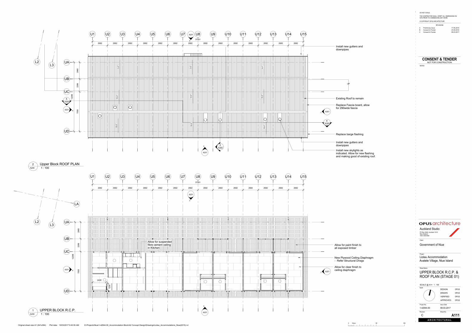
Replace Fascia board, allowfor 290wide fascia
Replace barge flashing
Install new gutters anddownpipes
Install new gutters anddownpipes
Install new skylights asindicated. Allow for new flashingand making good of existing roof.
Existing Roof to remain10.0
°
10.0
°
10.0
°10
.0°
10.0
°
10.0
°3.
0°3.0°
3.0°
37551
2682 2682 2682 2682 2682 2682 2682 2682 2682 2682 2682 2682 2682 2682
1229
8
7050
2288
2960
LA
U1 U2 U3 U4 U5 U6 U7 U8 U9 U10 U11 U12 U13 U14 U15
UA
UB
UC
UD
L2L3
A2011
A201
2
A201 4
A201
3
2400
1200
2682 2682 2682 2682 2682 2682 2682 2682 2682 2682 2682 2682 2682 2682
37551
1229
8
7050
2288
2960
New Plywood Ceiling Diaphragm- Refer Structural Drwgs
Allow for clear finish toceiling diaphragm
Allow for paint finish toall exposed timber
Allow for suspendedfibre cement ceilingin Kitchen
Sheet No.Revision
Plot date:Original sheet size A1 (841x594)
Sheet Name
Client
Project No.
SCALE @ A1=
DRAWN
VERIFIED
Issue Date
DESIGN
Auckland StudioPO Box 5848, Auckland 1010New Zealand+64 9 355 9500
REVISIONS
NOTES
APPROVED
A R C H I T E C T U R A L
North
Project
0 10mm 50 100
DO NOT SCALE
THE CONTRACTOR SHALL VERIFY ALL DIMENSIONS ONSITE PRIOR TO COMMENCING ANY WORK
© COPYRIGHT OPUS ARCHITECTURE
CONSENT & TENDERNOT FOR CONSTRUCTION
G:\Projects\Niue\1-42944.00_Accommodation Block\A2 Concept Design\Drawings\Liolau_Accommodations_Niue(2015).rvt10/03/2017 9:45:55 AM
1 : 100
08.03.2017
C A111
UPPER BLOCK R.C.P. &ROOF PLAN (STAGE 01)
Government of Niue
Liolau AccommodationAvatele Village, Niue Island
1-42944.00
OPUS
OPUS
OPUS
OPUS
1 : 100A200
Upper Block ROOF PLAN2
1 : 100A200
UPPER BLOCK R.C.P.1
A Preliminary Issue 17.06.2016B Consent & Tender 20.09.2016C Consent & Tender 08.03.2017

UP
DW
LA
A203
3
A2031
A203
2
A203 4
LB LC LD LE LF LG LH LI
U1
UAUB
UC
L1
L2
L3
1A301
2A301
3A301
46000
560012200780030004400220068004000
9896
2696
7200
New Plywood Ceiling Diaphragm- Refer Structural Drwgs
Allow for clear finish toceiling diaphragm
Allow for suspendedfibre cement ceilingin Kitchen
Allow for paint finish toall exposed timber
2400
1200
LA
A203
3
A2031
A203
2
A203 4
LB LC LD LE LF LG LH LI
UAUB
UC
L1
L2
L3
400
1A301
2A301
2A301
Replace Fascia board, allowfor 290wide fascia
Replace barge flashing
Install new gutters anddownpipes
560012200780030004400220068004000
9896
2696
7200
Install new gutters anddownpipes
Install new skylights asindicated. Allow for new flashingand making good of existing roof.
21.0
°
21.0
°
21.0
°21
.0°
21.0
°
21.0
°
Existing Roof to remain
Sheet No.Revision
Plot date:Original sheet size A1 (841x594)
Sheet Name
Client
Project No.
SCALE @ A1=
DRAWN
VERIFIED
Issue Date
DESIGN
Auckland StudioPO Box 5848, Auckland 1010New Zealand+64 9 355 9500
REVISIONS
NOTES
APPROVED
A R C H I T E C T U R A L
North
Project
0 10mm 50 100
DO NOT SCALE
THE CONTRACTOR SHALL VERIFY ALL DIMENSIONS ONSITE PRIOR TO COMMENCING ANY WORK
© COPYRIGHT OPUS ARCHITECTURE
CONSENT & TENDERNOT FOR CONSTRUCTION
G:\Projects\Niue\1-42944.00_Accommodation Block\A2 Concept Design\Drawings\Liolau_Accommodations_Niue(2015).rvt10/03/2017 9:45:57 AM
1 : 100
08.03.2017
C A112
LOWER BLOCK R.C.P. &ROOF PLAN (STAGE 02)
Government of Niue
Liolau AccommodationAvatele Village, Niue Island
1-42944.00
OPUS
OPUS
OPUS
OPUS
1 : 100A200
LOWER BLOCK R.C.P.2
1 : 100A200
Lower Block ROOF PLAN3
A Preliminary Issue 17.06.2016B Consent & Tender 20.09.2016C Consent & Tender 08.03.2017

0Lower Block F.L.
3300Lower Block C.L.
1975Upper Block F.L.
5015Upper Block C.L.
0Lower Block F.L.
3300Lower Block C.L.
1975Upper Block F.L.
5015Upper Block C.L.
0Lower Block F.L.
3300Lower Block C.L.
1975Upper Block F.L.
5015Upper Block C.L.
0Lower Block F.L.
3300Lower Block C.L.
1975Upper Block F.L.
5015Upper Block C.L.
Sheet No.Revision
Plot date:Original sheet size A1 (841x594)
Sheet Name
Client
Project No.
SCALE @ A1=
DRAWN
VERIFIED
Issue Date
DESIGN
Auckland StudioPO Box 5848, Auckland 1010New Zealand+64 9 355 9500
REVISIONS
NOTES
APPROVED
A R C H I T E C T U R A L
North
Project
0 10mm 50 100
DO NOT SCALE
THE CONTRACTOR SHALL VERIFY ALL DIMENSIONS ONSITE PRIOR TO COMMENCING ANY WORK
© COPYRIGHT OPUS ARCHITECTURE
CONSENT & TENDERNOT FOR CONSTRUCTION
G:\Projects\Niue\1-42944.00_Accommodation Block\A2 Concept Design\Drawings\Liolau_Accommodations_Niue(2015).rvt10/03/2017 9:46:03 AM
1 : 100
08.03.2017
C A200
PROPOSED SITEELEVATIONS
Government of Niue
Liolau AccommodationAvatele Village, Niue Island
1-42944.00
OPUS
OPUS
OPUS
OPUS
1 : 100A011
Proposed Site North Elevation1
1 : 100A011
Proposed Site East Elevation2
1 : 100A011
Proposed Site West Elevation3
1 : 100A011
Proposed Site South Elevation4
A Preliminary Issue 17.06.2016B Consent & Tender 20.09.2016C Consent & Tender 08.03.2017
STAGE 01
STAGE 02
1975Upper Block F.L.
5015Upper Block C.L.
UAUBUCUD
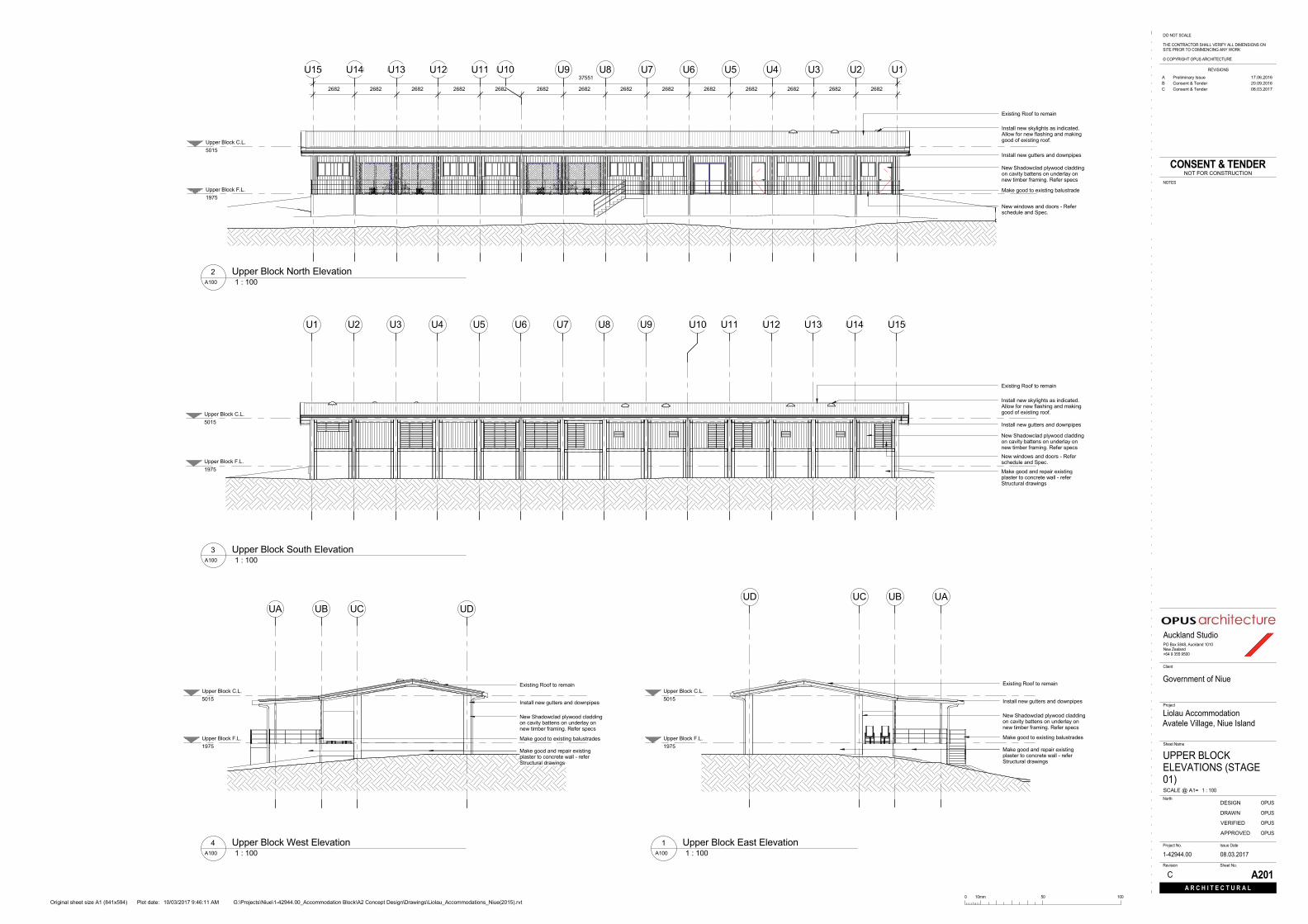
Install new gutters and downpipes
Existing Roof to remain
New Shadowclad plywood claddingon cavity battens on underlay onnew timber framing. Refer specs
Make good and repair existingplaster to concrete wall - referStructural drawings
Make good to existing balustrades
1975Upper Block F.L.
5015Upper Block C.L.
U1U2U3U4U5U6U7U8U9U10U11U12U13U14U1537551
26822682268226822682268226822682268226822682268226822682
Install new gutters and downpipes
Install new skylights as indicated.Allow for new flashing and makinggood of existing roof.
Existing Roof to remain
New Shadowclad plywood claddingon cavity battens on underlay onnew timber framing. Refer specs
Make good to existing balustrade
New windows and doors - Referschedule and Spec.
1975Upper Block F.L.
5015Upper Block C.L.
U1 U2 U3 U4 U5 U6 U7 U8 U9 U10 U11 U12 U13 U14 U15
Install new gutters and downpipes
Install new skylights as indicated.Allow for new flashing and makinggood of existing roof.
Existing Roof to remain
New Shadowclad plywood claddingon cavity battens on underlay onnew timber framing. Refer specs
Make good and repair existingplaster to concrete wall - referStructural drawings
New windows and doors - Referschedule and Spec.
1975Upper Block F.L.
5015Upper Block C.L.
UA UB UC UD
Install new gutters and downpipes
Existing Roof to remain
New Shadowclad plywood claddingon cavity battens on underlay onnew timber framing. Refer specs
Make good and repair existingplaster to concrete wall - referStructural drawings
Make good to existing balustrades
Sheet No.Revision
Plot date:Original sheet size A1 (841x594)
Sheet Name
Client
Project No.
SCALE @ A1=
DRAWN
VERIFIED
Issue Date
DESIGN
Auckland StudioPO Box 5848, Auckland 1010New Zealand+64 9 355 9500
REVISIONS
NOTES
APPROVED
A R C H I T E C T U R A L
North
Project
0 10mm 50 100
DO NOT SCALE
THE CONTRACTOR SHALL VERIFY ALL DIMENSIONS ONSITE PRIOR TO COMMENCING ANY WORK
© COPYRIGHT OPUS ARCHITECTURE
CONSENT & TENDERNOT FOR CONSTRUCTION
G:\Projects\Niue\1-42944.00_Accommodation Block\A2 Concept Design\Drawings\Liolau_Accommodations_Niue(2015).rvt10/03/2017 9:46:11 AM
1 : 100
08.03.2017
C A201
UPPER BLOCKELEVATIONS (STAGE01)
Government of Niue
Liolau AccommodationAvatele Village, Niue Island
1-42944.00
OPUS
OPUS
OPUS
OPUS
1 : 100A100
Upper Block East Elevation1
1 : 100A100
Upper Block North Elevation2
1 : 100A100
Upper Block South Elevation3
1 : 100A100
Upper Block West Elevation4
A Preliminary Issue 17.06.2016B Consent & Tender 20.09.2016C Consent & Tender 08.03.2017

0Lower Block F.L.
3300Lower Block C.L.
L1L2L372002696
Install new gutters and downpipes
Install new skylights as indicated.Allow for new flashing and makinggood of existing roof.
Existing Roof to remain
New masonry block wall - ReferStructural Drawings. Allow forconcrete sealer to exterior.
Exterior decking - Outdure woodplastic composite (refer specs)
0Lower Block F.L.
LA
3300Lower Block C.L.
LBLCLDLELFLGLHLI46000
400068002200440030007800122005600
1800 1800 2030 2030 2030 2030 2030 885 600 1800 1800 1800
1200
2000
480
1200
Replace barge flashing
Install new gutters and downpipes
Existing Roof to remain
New masonry block wall - ReferStructural Drawings. Allow forconcrete sealer to exterior.
New windows and doors - Referschedule and Spec.
0Lower Block F.L.
LA
3300Lower Block C.L.
LB LC LD LE LF LG LH LI
1800
46000
4000 6800 2200 4400 3000 7800 12200 5600
885 2030 885 885 2030 2030 203020302030 2030985
1200
2000
Install new gutters and downpipes
Install new skylights as indicated.Allow for new flashing and makinggood of existing roof.
Existing Roof to remain
New masonry block wall - ReferStructural Drawings. Allow forconcrete sealer to exterior.
New windows and doors - Referschedule and Spec.
Existing column to remain - makegood (refer structural drawings)
0Lower Block F.L.
3300Lower Block C.L.
L1 L2 L37200 2696 750
Install new gutters and downpipes
Install new skylights as indicated.Allow for new flashing and makinggood of existing roof.
Existing Roof to remain
New masonry block wall - ReferStructural Drawings. Allow forconcrete sealer to exterior.
Existing column to remain - makegood (refer structural drawings)
Sheet No.Revision
Plot date:Original sheet size A1 (841x594)
Sheet Name
Client
Project No.
SCALE @ A1=
DRAWN
VERIFIED
Issue Date
DESIGN
Auckland StudioPO Box 5848, Auckland 1010New Zealand+64 9 355 9500
REVISIONS
NOTES
APPROVED
A R C H I T E C T U R A L
North
Project
0 10mm 50 100
DO NOT SCALE
THE CONTRACTOR SHALL VERIFY ALL DIMENSIONS ONSITE PRIOR TO COMMENCING ANY WORK
© COPYRIGHT OPUS ARCHITECTURE
CONSENT & TENDERNOT FOR CONSTRUCTION
G:\Projects\Niue\1-42944.00_Accommodation Block\A2 Concept Design\Drawings\Liolau_Accommodations_Niue(2015).rvt10/03/2017 9:46:13 AM
1 : 100
08.03.2017
C A203
LOWER BLOCKELEVATIONS (STAGE02)
Government of Niue
Liolau AccommodationAvatele Village, Niue Island
1-42944.00
OPUS
OPUS
OPUS
OPUS
1 : 100A101
Lower Block East Elevation1
1 : 100A101
Lower Block North Elevation2
1 : 100A101
Lower Block South Elevation3
1 : 100A101
Lower Block West Elevation4
A Preliminary Issue 17.06.2016B Consent & Tender 20.09.2016C Consent & Tender 08.03.2017

1975Upper Block F.L.
5015Upper Block C.L.
UAUBUCUD
FOUNDATIONS ARE INDICATIVE ONLY- REFER STRUCTURAL REPORT
D36D44
1975Upper Block F.L.
5015Upper Block C.L.
U12U13U14U15
FOUNDATIONS ARE INDICATIVE ONLY- REFER STRUCTURAL REPORT
W16
D39
W17 W18
D42
1975Upper Block F.L.
5015Upper Block C.L.
2300
U1U2U3U4U5U6U7U8U9U10U11U12
FOUNDATIONS ARE INDICATIVE ONLY- REFER STRUCTURAL REPORT
2A400
W18
D42
W26
W25W24W23
W22W21
W20W19
D43 D46
Sheet No.Revision
Plot date:Original sheet size A1 (841x594)
Sheet Name
Client
Project No.
SCALE @ A1=
DRAWN
VERIFIED
Issue Date
DESIGN
Auckland StudioPO Box 5848, Auckland 1010New Zealand+64 9 355 9500
REVISIONS
NOTES
APPROVED
A R C H I T E C T U R A L
North
Project
0 10mm 50 100
DO NOT SCALE
THE CONTRACTOR SHALL VERIFY ALL DIMENSIONS ONSITE PRIOR TO COMMENCING ANY WORK
© COPYRIGHT OPUS ARCHITECTURE
CONSENT & TENDERNOT FOR CONSTRUCTION
G:\Projects\Niue\1-42944.00_Accommodation Block\A2 Concept Design\Drawings\Liolau_Accommodations_Niue(2015).rvt10/03/2017 9:46:18 AM
1 : 50
08.03.2017
C A300
UPPER BLOCKSECTIONS (STAGE 01)
Government of Niue
Liolau AccommodationAvatele Village, Niue Island
1-42944.00
OPUS
OPUS
OPUS
OPUS
1 : 50A100
Upper Block Cross Section3 1 : 50A100
Upper Block Long Section - 14
1 : 50A100
Upper Block Long Section - 25
A Preliminary Issue 17.06.2016B Consent & Tender 20.09.2016C Consent & Tender 08.03.2017

0Lower Block F.L.
3300Lower Block C.L.
L1 L2 L3
2600 7200 2696
FOUNDATIONS ARE INDICATIVE ONLY- REFER STRUCTURAL REPORT
D22D10
0Lower Block F.L.
LA
3300Lower Block C.L.
LB LC LD
46 m²
MENS DORM101-27
5 m²
WAITING AREA101-30
7 m²
STORE101-25
27 m²
MENS ABLUTION101-241800 1800
4000 6800 2200
FOUNDATIONS ARE INDICATIVE ONLY- REFER STRUCTURAL REPORT
W09 D29 D30W02 W03
0Lower Block F.L.
3300Lower Block C.L.
LE LF LG LH LI
20 m²
KITCHEN101-23
53 m²
DINING HALL101-22
84 m²
CULTURAL HALL101-21
5 m²
HALLWAY101-20
15 m²
CONFERENCEROOM 02
101-1927 m²
MENS ABLUTION101-24
3000 7800 12200 5600
FOUNDATIONS ARE INDICATIVE ONLY- REFER STRUCTURAL REPORT
D14D13D12D11D10 D15
W04 W05
D09D07
Sheet No.Revision
Plot date:Original sheet size A1 (841x594)
Sheet Name
Client
Project No.
SCALE @ A1=
DRAWN
VERIFIED
Issue Date
DESIGN
Auckland StudioPO Box 5848, Auckland 1010New Zealand+64 9 355 9500
REVISIONS
NOTES
APPROVED
A R C H I T E C T U R A L
North
Project
0 10mm 50 100
DO NOT SCALE
THE CONTRACTOR SHALL VERIFY ALL DIMENSIONS ONSITE PRIOR TO COMMENCING ANY WORK
© COPYRIGHT OPUS ARCHITECTURE
CONSENT & TENDERNOT FOR CONSTRUCTION
G:\Projects\Niue\1-42944.00_Accommodation Block\A2 Concept Design\Drawings\Liolau_Accommodations_Niue(2015).rvt10/03/2017 9:46:22 AM
1 : 50
08.03.2017
C A301
LOWER BLOCKSECTIONS (STAGE 02)
Government of Niue
Liolau AccommodationAvatele Village, Niue Island
1-42944.00
OPUS
OPUS
OPUS
OPUS
1 : 50A101
Lower Block Cross Section1 1 : 50A101
Lower Block Long Section - 12
1 : 50A101
Lower Block Long Section - 23
A Preliminary Issue 17.06.2016B Consent & Tender 20.09.2016C Consent & Tender 08.03.2017

3A300
U5 U6 U7 U8 U9 U10
UC
UD
5A300
4A400
7A400
8A400
6A400
5A400
2A400
3A400
D34W11 W12
D35 D36
D43
D44D45
D46
W22 W21W23W24W25
43 m²
WOMENS DORM101-38
34 m²
STUDIO UNIT 01101-37
34 m²
STUDIO UNIT 02101-36
U7
UC
Existing concrete column - makegood as per Structural Specs.
New Structural wall with Acousticinsulation. Paint finish - ReferSpecs
Powdercoated aluminiumjoinery with 19mm thick timberreveal fixed to timber frame
DPC between Concreteand timber
Solid exterior plywood screen fixed toexisting concrete column with SS fixingand bracket - F8 grade Ecoply
U7
UD
50mm thick timber frame withbreezeway Altair 152 - Refer Specs
SS flyscreen mesh fixed with35x20mm timber batten with SSscrews
Existing concrete column - makegood as per Structural Specs.
New PFC portals - ReferStructural Drawings for sizeand finish
New Structural wall with Acousticinsulation. Paint finish - ReferSpecs
New Ecoply F8 grade lined Timberframed wall - Refer Specs
Seal and tape external opening andseal wall window inserts with sealant(Refer specs for products)
U9
UD
Existing concrete column - makegood as per Structural Specs.
New PFC portals - ReferStructural Drawings for sizeand finish
New Structural wall with Acousticinsulation. Paint finish - ReferSpecs
New 6mm fibre cement sheetlining for all wet areas.
New cladding - Grooved Shadowcladsystem by Carter Holt Harvey.Install under strict manufacturerrecommendation.
New ceramic wall tiles (Showerwalls only) over 6mm JamesHardie fibre cement lining - ReferSpec for selection.
U9
New Structural wall with Acousticinsulation. Paint finish - ReferSpecs
New 6mm fibre cement sheetlining for all wet areas.
New ceramic wall tiles (Showerwalls only) over 6mm JamesHardie fibre cement lining - ReferSpec for selection.
New Ecoply F8 grade lined Timberframed wall - Refer Specs
New Ecoply F8 grade lined Timberframed wall - Refer Specs
New 3 panel wardobe slider door -Refer Spec and Schedule
Proprietary high level timber shelving withfull length hanging rail - client to select
U8
Existing concrete column - makegood as per Structural Specs.
New PFC portals - ReferStructural Drawings for sizeand finish
Seal and tape external opening andseal wall window inserts with sealant(Refer specs for products)
New Ecoply F8 grade lined Timberframed wall - Refer Specs
Powdercoated aluminiumjoinery with 19mm thick timberreveal fixed to timber frame
DPC between Concrete and timber
1975Upper Block F.L.
5015Upper Block C.L.
UD
SS flyscreen mesh fixed with 35x20mmtimber batten with SS screws
Existing concrete beam - Make goodas per Structural Specs. allow to lineinside face with Ecoply F8 grade linedTimber framed wall - Refer Specs
New PFC portals - Refer StructuralDrawings for size and finish
New Structural ceiling Diaphragmwith Acoustic insulation. Paint finish -Refer Specs and drawings.
Seal and tape external opening andseal wall window inserts with sealant(Refer specs for products)
New cladding - Grooved Shadowcladsystem by Carter Holt Harvey. Install understrict manufacturer recommendation.
New Ecoply F8 grade lined Timberframed wall / strapping - Refer Specs
Powdercoated aluminum joinery with 19mmthick timber reveal fixed to timber frame
DPC between Concrete and timber
50mm thick timber frame with breezewayAltair 152 Louvre window- Refer Specs
Existing roof to remain. Allow forpaint finish to all exposed timber
Existing concrete wall - Make good asper Structural Specs
New concrete slab on existing concreteslab - Refer structural drawings
UC
Sheet No.Revision
Plot date:Original sheet size A1 (841x594)
Sheet Name
Client
Project No.
SCALE @ A1=
DRAWN
VERIFIED
Issue Date
DESIGN
Auckland StudioPO Box 5848, Auckland 1010New Zealand+64 9 355 9500
REVISIONS
NOTES
APPROVED
A R C H I T E C T U R A L
North
Project
0 10mm 50 100
DO NOT SCALE
THE CONTRACTOR SHALL VERIFY ALL DIMENSIONS ONSITE PRIOR TO COMMENCING ANY WORK
© COPYRIGHT OPUS ARCHITECTURE
CONSENT & TENDERNOT FOR CONSTRUCTION
G:\Projects\Niue\1-42944.00_Accommodation Block\A2 Concept Design\Drawings\Liolau_Accommodations_Niue(2015).rvt10/03/2017 9:46:23 AM
As indicated
08.03.2017
B A400
GENERAL DETAILS(STAGE 01)
Government of Niue
Liolau AccommodationAvatele Village, Niue Island
1-42944.00
OPUS
OPUS
OPUS
OPUS
1 : 50A100
Upper Block G.A. PLAN - Callout 11
1 : 10A400
Upper Block - Detail 14
1 : 10A400
Upper Block - Detail 47 1 : 10A400
Upper Block - Detail 58
1 : 10A400
Upper Block - Detail 36
1 : 10A400
Upper Block - Plan Detail 25
1 : 10A300
Upper Block Section Detail 12 1 : 10A400
Upper Block Section Detail 23
A Consent & Tender 20.09.2016B Consent & Tender 08.03.2017
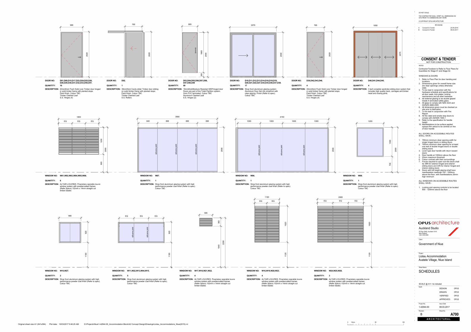
D01,D09,D15,D17,D23,D24,D25,D26,D28,D29,D30,D31,D32,D33,D50,D51.
DOOR NO:
DESCRIPTION: 40mmthick Flush Solid core Timber door hingedin solid timber frame with planted stops.Paint finish. Colour TBCTimber Clashed LeafS.S. Hinges (4)
16QUANTITY:
D02.DOOR NO:
DESCRIPTION: 38mmthick Cavity slider Timber door slidingon solid timber frame with planted stops.Paint finish. Colour TBCTimber Clashed LeafS.S. Rollers
1QUANTITY:
D03,D04,D05,D06,D07,D08,D47,D48,D49
DOOR NO:
DESCRIPTION: 18mmthickMoisture Resistant MDFhinged doorDoors are part of the Toilet Partition system.2mm PVC laminated. Colour TBCAluminium Clashed LeafS.S. Hinges (2)
09QUANTITY:
D10,D11,D12,D13,D14,D16,D18,D19,D20,D21,D22,D27,D34,D35,D36,D37,D38.
DOOR NO:
DESCRIPTION: Shop front aluminium glazing system-Aluminium Door Set into shopfront withclear glazing. Finish (Refer to spec).Colour TBC
17QUANTITY:
D39,D42,D43,D46.DOOR NO:
DESCRIPTION: 40mmthick Flush Solid core Timber door hingedin solid timber frame with planted stops.Paint finish. Colour TBCTimber Clashed LeafS.S. Hinges (4)
4QUANTITY:
D40,D41,D44,D45.DOOR NO:
DESCRIPTION: 3 leaf complete wardrobe sliding door system thatincludes high quality track, carriages and timberhead and closing jamb.
4QUANTITY:
W01,W02,W03,W04,W05,W08.WINDOW NO:
DESCRIPTION: ALTAIR LOUVRES. Proprietary operable louvrewindow system with powdercoated frames(Refer Specs) 152mm x 14mm straight cuttimber blades
6QUANTITY:
W07.WINDOW NO:
DESCRIPTION: Shop front aluminium glazing system with highperformance powder coat finish (Refer to spec).Colour TBC
1QUANTITY:
W06.WINDOW NO:
DESCRIPTION: Shop front aluminium glazing system with highperformance powder coat finish (Refer to spec).Colour TBC
1QUANTITY:
W09.WINDOW NO:
DESCRIPTION: Shop front aluminium glazing system with highperformance powder coat finish (Refer to spec).Colour TBC
1QUANTITY:
W10,W27.WINDOW NO:
DESCRIPTION: Shop front aluminium glazing system with highperformance powder coat finish (Refer to spec).Colour TBC
2QUANTITY:
W11,W22,W13,W44,W15.WINDOW NO:
DESCRIPTION: Shop front aluminium glazing system with highperformance powder coat finish (Refer to spec).Colour TBC
5QUANTITY:
W17,W18,W21,W22.WINDOW NO:
DESCRIPTION: ALTAIR LOUVRES. Proprietary operable louvrewindow system with powdercoated frames(Refer Specs) 152mm x 14mm straight cuttimber blades
4QUANTITY:
W16,W19,W20,W23.WINDOW NO:
DESCRIPTION: ALTAIR LOUVRES. Proprietary operable louvrewindow system with powdercoated frames(Refer Specs) 152mm x 14mm straight cuttimber blades
4QUANTITY:
W24,W25,W26.WINDOW NO:
DESCRIPTION: ALTAIR LOUVRES. Proprietary operable louvrewindow system with powdercoated frames(Refer Specs) 152mm x 14mm straight cuttimber blades
3QUANTITY:
2070
2000
985
2020
EQEQEQ
1800
1200
800
2000
silic
one
join
t
silic
one
join
t
silic
one
join
t
1000 1000 1000 1000
2000
4150
890890890840
silic
one
join
t
silic
one
join
t
silic
one
join
t
2000
3560
700
1300
2000
1200
200
1800
2000
685760
2020
1100
920
980
silic
one
join
t
silic
one
join
t
EQ EQ EQ
1100
920
EQ EQ
1100
1620
1120
360
1840
585
2200
EQ EQ EQ
2065
1620
1120
2020
785 1950
2075
Sheet No.Revision
Plot date:Original sheet size A1 (841x594)
Sheet Name
Client
Project No.
SCALE @ A1=
DRAWN
VERIFIED
Issue Date
DESIGN
Auckland StudioPO Box 5848, Auckland 1010New Zealand+64 9 355 9500
REVISIONS
NOTES
APPROVED
A R C H I T E C T U R A L
North
Project
0 10mm 50 100
DO NOT SCALE
THE CONTRACTOR SHALL VERIFY ALL DIMENSIONS ONSITE PRIOR TO COMMENCING ANY WORK
© COPYRIGHT OPUS ARCHITECTURE
CONSENT & TENDERNOT FOR CONSTRUCTION
G:\Projects\Niue\1-42944.00_Accommodation Block\A2 Concept Design\Drawings\Liolau_Accommodations_Niue(2015).rvt10/03/2017 9:46:25 AM
As indicated
08.03.2017
B A700
SCHEDULES
Government of Niue
Liolau AccommodationAvatele Village, Niue Island
1-42944.00
OPUS
OPUS
OPUS
OPUS
1. Refer to Floor Plan for door handing andlocations
2. Dimensions given for overall frame sizeare clear openings unless otherwisestate.
3. To be read in conjunction with thehardware schedule and specifications forall door seals, kick plates, lockingmechanisms and all other hardware
4. All external glazing to be double glazedGrade A laminated safety glass
5. All glass to comply with NZS 4223 andAS/NZS 4666:2000
6. All dimensions given must be checked onsite prior to fabrication
7. To be read in conjunction with FireReport
8. All fire rated and smoke stop doors tocomply with AS/NZS 1905.1
9. Refer to the specification for handleheight
10. Manifestations to be surface appliedopaque film setout to be centred on lineof door handle
ALL DOORS ON ACCESSIBLE ROUTESSHALL HAVE:-
1. 760mm minimum clear opening width forsingle hinged doors or sliding doors
2. 760mm minimum clear opening for at leastone leaf of double hinged doors or doublesliding doors
3. Lever type door handle with return towarddoors
4. Door handle at 1000mm above the floor5. 20mm maximum threshold6. Colour contrast with their surroundings7. Forces required to open non-fire doors shall
be 38N for exterior hinged and exteriorsliding doors and 22N for interior hinged andinterior sliding doors
8. Doors with full height glazing shall havemanifestation markings 700 - 1000mmabove the floor, with manifestations 20mmhigh minimum
ALL WINDOWS ON ACCESSIBLE ROUTESSHALL HAVE:-
1. Locking and opening controls to be located900 - 1200mm above the floor
A Consent & Tender 20.09.2016B Consent & Tender 08.03.2017
WINDOWS & DOORS
Contractor/Tenderer to Refer to Floor Plans forQuantities for Stage 01 and Stage 02.


