Onsite Wastewater Treatment System Repair of Failure/Malfunction ...

Rev. 11/2017
Missouri Laws Accompanied by
Department of Health and Senior Services Rules
Governing Onsite Wastewater Treatment Systems
Missouri Department of Health and Senior Services
Bureau of Environmental Health Services
i
Table of Contents
MISSOURI LAWS FOR ON-SITE DISPOSAL SYSTEMS
Page 701.025 Definitions ................................................................................................................................. 1
701.027 Scope of coverage ...................................................................................................................... 1
701.029 Operation of on-site sewage disposal system, restrictions......................................................... 1
701.031 Disposal of sewage, who, how, exception ................................................................................. 1
701.033 Department of Health and Senior Services – powers and duties – rules, procedure ................. 2
701.035 Local regulations and standards, requirements – private right to
action not preempted.................................................................................................................. 2
701.037 Violations, notice of, contents, prosecuting attorney to institute proceedings,
When – emergency situation, when ........................................................................................... 2
701.038 Sewage complaints, investigation by department, when – right to
inspect adjoining property, procedure requiring notice, exception ............................................ 3
701.039 Clean water commission may take action, rules not to conflict ................................................ 3
701.040 Standards for sewage tanks, lateral lines and operation of on-site
sewage disposal systems, duties of department – rules authorized ........................................... 4
701.043 State standards, content ............................................................................................................. 4
701.046 Modification or major repair to on-site sewage disposal system,
Requirements – form – fee, how set – additional fee may be set for
training contractors performing percolation tests ...................................................................... 5
701.047 City or county may adopt more restrictive standards ................................................................ 5
701.048 Modifying or repair of on-site sewage disposal system,
noncompliance with standards prohibited ................................................................................. 5
701.049 Fees collected by department to be deposited in public health
service fund, purpose ................................................................................................................. 5
ii
701.050 Construction or repair notice – requirements and inspection –
failure to comply with standards, effect..................................................................................... 5
701.051 Inspections by department, who may request – fee –
department may license contractors to inspect .......................................................................... 6
701.052 Violator found guilty not to begin construction for another person
without bond or letter of credit – forfeiture when, effect – emergency
repairs of – effect ....................................................................................................................... 6
701.053 Registered on-site disposal system contractor, form, qualifications –
registration issued by county to be deemed state registration.................................................... 6
701.054 Registration of contractor may be denied, suspended or revoked,
procedure, appeal – reregistration application may be made when –
official roster of contractors published by department, content ................................................ 7
701.055 Property owners may install, modify or clean their own on-site
sewage disposal system in compliance with requirements, no permit
required for cleaning .................................................................................................................. 7
701.057 Violations, penalties and fines ................................................................................................... 7
701.059 Creation of a nuisance on certain residential property is an
infraction – sewage disposal system in violation, statute of limitations
starts to run, when ...................................................................................................................... 7
The statutes in this booklet are current as of January, 2016.
The headnotes, footnotes, annotations and index of the Missouri Revised Statutes, are used by permission of the
Joint committee on Legislative Research, the copyright holder.

iii
DEPARTMENT OF HEALTH AND SENIOR SERVICES RULES
19 CSR 20-3.060 Minimum Construction Standards for On-Site
Sewage Disposal Systems Page
(1) General ................................................................................................................ 8
(A) Definitions ................................................................................................. 8
(B) Applicability ............................................................................................ 11
(C) Responsibilities ........................................................................................ 11
(D) Minimum Set-Back Distances ................................................................. 11
(E) Sewage Flow Rates .................................................................................. 11
(2) Site Evaluation ................................................................................................... 15
(A) Evaluation of all Proposed Sites .............................................................. 15
(B) Preliminary Soils Information ................................................................. 15
(C) Soil Permeability and Soil Percolation .................................................... 15
(D) Procedures for Percolation Tests and Profile Holes ................................ 16
(3) Building Sewers ................................................................................................. 17
(A) Size .......................................................................................................... 17
(B) Slope ........................................................................................................ 17
(C) Cleanouts ................................................................................................. 17
(D) Connection to sewage tank ...................................................................... 17
(4) Sewage Tanks .................................................................................................... 17
(A) General ..................................................................................................... 17
(B) Septic Tanks ............................................................................................. 18
(C) Location ................................................................................................... 19
(D) Solids Removal ........................................................................................ 19
(E) Aeration Units .......................................................................................... 19
(5) Absorption Systems ........................................................................................... 20
(A) Absorption Trenches ................................................................................ 20
(B) Possible Modifications to Standard Absorption Systems ........................ 23
(6) Alternative Systems ........................................................................................... 24
(A) General ..................................................................................................... 24
(B) Adoption and Use .................................................................................... 24
(C) Low Pressure Pipe System ....................................................................... 24
(D) Wastewater Stabilization Ponds (Lagoon) .............................................. 25
(E) Elevated Sand Mounds ............................................................................. 27
(F) Holding Tanks .......................................................................................... 28
(G) Sand Filters .............................................................................................. 29
iv
(H) Drip Soil Absorption ............................................................................... 33
(I) Wetlands .................................................................................................... 33
(J) Privy .......................................................................................................... 36
(K) Other Systems .......................................................................................... 36
(L) Variances .................................................................................................. 36
(7) Detailed Soils Evaluation .................................................................................. 37
(A) General ..................................................................................................... 37
(B) Adoption and Use .................................................................................... 37
(C) Site Evaluation is ..................................................................................... 37
(D) Site Evaluation shall be made .................................................................. 37
(E) Topography and Landscape Position ....................................................... 37
(F) Soil Characteristics ................................................................................... 38
(G) Soil Drainage ........................................................................................... 40
(H) Soil Thickness .......................................................................................... 40
(I) Restrictive Horizons .................................................................................. 40
(J) Other Applicable Factors .......................................................................... 41
(K) Determination of Overall Site Suitability ................................................ 41
(L) Site Classification .................................................................................... 41
(M) Design Criteria ........................................................................................ 41
19 CSR 20-3.070 Requirements for On-Site Wastewater Treatment Systems ................ 44
Inspectors/Evaluators
19 CSR 20-3.080 Requirements for Percolation Testers or On-Site Soil Evaluators
and Registered On-Site Wastewater Treatment System Installers ..... 47
Missouri Department of Health and Senior Services Health and Public Health Offices Map ... 51
Missouri Department of Natural Resources Regional and Satellite Offices Map ...................... 52
MISSOURI LAWS FOR
ON-SITE DISPOSAL SYSTEMS
1
701.025. Definitions. — As used in sections 701.025 to 701.059, unless the context otherwise requires, the following terms mean:
(1) "Department", the department of health and senior services of the state of Missouri;
(2) "Director", the director of the department of health and senior services or the designee of the director;
(3) "Existing system", an on-site sewage disposal system in operation prior to September 1, 1995; (4) "Human excreta", undigested food and by-
products of metabolism which are passed out of the human body;
(5) "Imminent health hazard", a condition which is likely to cause an immediate threat to life or a serious risk to the health, safety, and welfare of the public if immediate action is not taken;
(6) "Major modification" or "major repair", the redesigning and alteration of an on-site sewage system by relocation of the system or a part of the system, replacement of the septic tank or construction of a new absorption field;
(7) "Nuisance", sewage, human excreta or other human organic waste discharged or exposed on the owner's land or any other land from an on-site sewage disposal system in a manner that makes it a potential instrument or medium for the breeding of flies and mosquitoes, the production of odors, or the transmission of disease to or between a person or persons, or which contaminates surface waters* or groundwater;
(8) "On-site sewage disposal system", any system handling or treatment facility receiving domestic sewage which discharges into a subsurface soil absorption system and discharges less than three thousand gallons per day;
(9) "On-site sewage disposal system contractor", any person who constructs, alters, repairs, or extends an on-site sewage disposal system on behalf of, or under contract with, the property owner;
(10) "Person", any individual, group of individuals, association, trust, partnership, corporation, person doing business under an assumed name, the state of Missouri or any department thereof, or any political subdivision of this state;
(11) "Property owner", the person in whose name legal title to the real estate is recorded;
(12) "Sewage" or "domestic sewage", human excreta and wastewater, including bath and toilet waste, residential laundry waste, residential kitchen waste and other similar waste from household or establishment appurtenances. Sewage and domestic sewage waste are further categorized as:
(a) "Blackwater", waste carried off by toilets, urinals and kitchen drains;
(b) "Graywater", all domestic waste not covered in paragraph (a) of this subdivision, including bath, lavatory, laundry, and sink waste;
(13) "Subdivision", land divided or proposed to be divided for predominantly residential purposes into such
parcels as required by local ordinances, or in the absence of local ordinances, "subdivision" means any land which is divided or proposed to be divided by a common owner or owners into three or more lots or parcels, any of which contains less than three acres, or into platted or unplatted units, any of which contains less than three acres, as a part of a uniform plan of development;
(14) “Subsurface soil absorption system", a system for the final renovation of the sewage tank effluent and return of the renovated wastewater to the hydrologic cycle, including the lateral lines, the perforated pipes, the rock material and the absorption trenches. Included within the scope of this definition are: sewage tank absorption systems, privies, chemical toilets, single-family lagoons and other similar systems; except that a subsurface sewage disposal system does not include a sewage system regulated pursuant to chapter 644;
(15) "Waste", sewage, human excreta or domestic sewage. (L.1986 H.B. 1101§ 1, A.L. 1994 S.B. 446)
*Word "waters" does not appear in original rolls.
701.027. Scope of coverage. — Sections 701.025 to 701.059 pertains to maximum daily flows of sewage of three thousand gallons or less and to sewage treatment facilities that have a designed maximum daily flow or an actual maximum daily flow of three thousand gallons or less. (L. 1986 H.B. 1101 § 2, A.L. 1994 S.B. 446)
701.029. Operation of on-site sewage disposal system, restrictions. — No person or property owner may operate an on-site sewage disposal system or transport and dispose of waste removed there from in such a manner that may result in the contamination of surface waters or groundwater or present a nuisance or imminent health hazard to any other person or property owner and that does not comply with the requirements of sections 701.025 to 701.059 and the on-site sewage disposal rules promulgated under sections 701.025 to 701.059 by the department. (L. 1986 H.B. 1101 § 3, A.L. 1994 S.B. 446)
701.031. Disposal of sewage, who, how, exception. — Property owners of all buildings where people live, work or assemble shall provide for the sanitary disposal of all domestic sewage. Except as provided in this section, sewage and waste from such buildings shall be disposed of by discharging into a sewer system regulated pursuant to chapter 644, or shall be disposed of by discharging into an on-site sewage disposal system operated as defined by rules promulgated pursuant to sections 701.025 to 701.059. Any person installing on-site sewage disposal systems shall be registered to do so by the department of health and senior services. The owner of a single-family residence lot consisting of three acres or more, or the owner of a residential lot consisting of ten acres or more with no
2
single-family residence on-site sewage disposal system located within three hundred sixty feet of any other on-site sewage disposal system and no more than one single- family residence per each ten acres in the aggregate, except lots adjacent to lakes operated by the Corps of Engineers or by a public utility, shall be excluded from the provisions of sections 701.025 to 701.059 and the rules promulgated pursuant to sections 701.025 to 701.059, including provisions relating to the construction, operation, major modification and major repair of on-site disposal systems, when all points of the system are located in excess of ten feet from any adjoining property line and no effluent enters an adjoining property, contaminates surface waters or groundwater or creates a nuisance as determined by a readily available scientific method. Except as provided in this section, any construction, operation, major modification or major repair of an on-site sewage disposal system shall be in accordance with rules promulgated pursuant to sections 701.025 to 701.059, regardless of when the system was originally constructed. The provisions of subdivision (2) of subsection 1 of section 701.043 shall not apply to lots located in subdivisions under the jurisdiction of the department of natural resources which are required by a consent decree, in effect on or before May 15, 1984, to have class 1, National Sanitation Federation (NSF) aerated sewage disposal systems. (L. 1986 H.B. 1101 § 4, A.L. 1994 S.B. 446, A.L. 1999 H.B. 216, A.L.
2004 H.B. 1433, A.L. 2005 H.B. 617)
*This section was contained in H.B. 617, 2005, but no changes were
made.
701.033. Department of health and senior services — powers and duties — rules, procedure. — 1. The department shall have the power and duty to:
(1) Promulgate such rules and regulations as are necessary to carry out the provisions of sections 701.025 to 701.059;
(2) Cause investigations to be made when a violation of any provision of sections 701.025 to 701.059 or the on-site sewage disposal rules promulgated under sections
701.025 to 701.059 is reported to the department; (3) Enter at reasonable times and determining
probable cause that a violation exists, upon private or public property for the purpose of inspecting and investigating conditions relating to the administration and enforcement of sections 701.025 to 701.059 and the on-site sewage disposal rules promulgated under sections 701.025 to 701.059;
(4) Authorize the trial or experimental use of innovative systems for on-site sewage disposal, after consultation with the staff of the Missouri clean water commission, upon such conditions as the department may set;
(5) Provide technical assistance and guidance to any other administrative authority in the state on the regulation and enforcement of standards for individual on-site sewage
disposal systems, at the request of such other administrative authority, or when the department determines that such assistance or guidance is necessary to prevent a violation of sections 701.025 to 701.059.
2. No rule or portion of a rule promulgated under the authority of sections 701.025 to 701.059 shall become effective unless it has been promulgated pursuant to the provisions of section 536.024. (L. 1986 H.B. 1101 § 5, A.L. 1993 S.B. 52, A.L. 1994 S.B. 446, A.L.
1995 S.B. 3, A.L. 2004 H.B. 1433, A.L. 2011 H.B. 89) Effective 7-11-11
CROSS REFERENCE:
Nonseverability clause, 640.099
701.035. Local regulations and standards, requirements — private right to action not preempted. — Sections 701.025 to 701.059 shall not prohibit the enforcement of ordinances of political subdivisions establishing a system for the regulation and inspection of on-site sewage disposal con- tractors and a minimum code of standards for design, construction, materials, operation and maintenance of on-site sewage disposal systems, for the transportation and disposal of wastes there from and for on-site sewage disposal systems servicing equipment, provided such ordinance establishes a system at least equal to state regulation and inspection. Nor shall sections 701.025 to 701.059 be interpreted so as to preempt any private right of action which might otherwise exist. Nothing in sections 701.025 to 701.059 shall be construed to prohibit a political subdivision from enacting and enforcing standards which are more stringent than the provisions of sections 701.025 to 701.059 and rules promulgated pursuant thereto. (L. 1986 H.B. 1101 § 6, A.L. 1994 S.B. 446)
701.037. Violations, notice of, contents, prosecuting attorney to institute proceedings, when — emergency situation, when. — 1. Whenever the director determines that there are reasonable grounds to believe that there has been violation of any provision of sections 701.025 to 701.059 or the rules promulgated under sections 701.025 to 701.059, the director shall give notice of such alleged violation to the person responsible, as herein provided. The notice shall:
(1) Be in writing; (2) Include a statement of the reasons for the issuance
of the notice; (3) Allow reasonable time as determined by the
director for the performance of any act it requires; (4) Be served upon the owner, operator or contractor,
as the case may require, provided that such notice or order shall be deemed to have been properly served upon such person when a copy thereof has been sent by registered or certified mail to the person's last known address, as listed in the local property tax records concerning such property, or when such person has been served with such notice by any other method authorized by the laws of this state;
(5) Contain an outline of remedial action which is
3
required to effect compliance with sections 701.025 to 701.059 and the rules promulgated under sections 701.025 to 701.059.
2. Existing systems, as defined in section 701.025,
shall not be inspected, unless the director determines that there are reasonable grounds to believe that there has been a violation of any provision of sections 701.025 to 701.059.
3. If an aggrieved person files a written request for a
hearing within ten days of the date of receipt of a notice, a hearing shall be held within twenty days from the date of the receipt of the notice, before the department director, to review the appropriateness of the remedial action. The director shall issue a written decision within thirty calendar days of the date of the hearing. Any final decision of the director may be appealed to the administrative hearing commission in the manner provided in chapter 621, or may at the option of the aggrieved person be appealed to the circuit court of the county wherein the offense is alleged to have occurred for a trial de novo on the merits. Any decision of the administrative hearing commission may be appealed as provided in sections 536.100 to 536.140.
4. Any city or county that has adopted the state
standard, or the department, may require a property owner to abate a nuisance or repair a malfunctioning on-site sewage disposal system on the owner's property not later than the thirtieth day from which the owner receives notification from the city, county or department of the malfunctioning system or a final written order from the director, if a hearing or hearings were held pursuant to subsections 2 and 3 of this section. If weather conditions prevent the abatement of the nuisance or repair of the system within the thirty-day period or if the owner is unable, after reasonable effort, to obtain the services of a contractor or repair service within the thirty-day period, the abatement of the nuisance or repair of the system shall be made, weather permitting, no later than sixty days after notification. Such extension for abatement or repair shall be subject to approval by the city, county or department. The department may assess an administrative penalty on the property owner of no more than fifty dollars per day for each day that the on-site sewage disposal system remains unrepaired beyond the last day permitted by this section for the abatement or repair. All administrative penalties collected by the department under the provisions of this section shall be deposited in the state treasury to the credit of the general revenue fund.
5. The prosecuting attorney of the county in which any
noncompliance or violation of sections 701.025 to 701.059 or any rule promulgated under sections 701.025 to 701.059 is occurring shall, at the request of the city, county or department, institute appropriate proceedings for correction in cases of noncompliance with or violation of the provisions
of sections 701.025 to 701.059 and any rules promulgated under sections 701.025 to 701.059.
6. When it is determined by the department that an
emergency exists which requires immediate action to protect the health and welfare of the public, the department is authorized to seek a temporary restraining order and injunction. Such action shall be brought at the request of the director of the department by the prosecuting attorney of the county in which the violation occurred. When such conditions are corrected and the health of the people of the state of Missouri is no longer threatened, the department shall request that such temporary restraining order and injunction be dissolved. For the purposes of this subsection, an “emergency” means any set of circumstances that constitute an imminent health hazard or the threat of an imminent health hazard as defined in section 701.025. (L. 1986 H.B. 1101 § 7, A.L. 1994 S.B. 446, A.L. 2004 H.B. 1433)
701.038. Sewage complaints, investigation by department, when — right to inspect adjoining property, procedure requiring notice, exception. — 1. The department of health and senior services or any of its agents may not investigate a sewage complaint except when necessary as part of a communicable disease investigation unless the complaint is received from an aggrieved party or an adjacent landowner. The department of health and senior services or any of its agents may enter any adjoining property if necessary when they are making an inspection pursuant to this section. The necessity for entering such adjoining property shall be stated in writing and the owner of such property shall be notified before the department or any of its agents may enter, except that, if an imminent health hazard exists, such notification shall be attempted but is not required.
2. If the department or its agents make an investigation pursuant to a complaint as described in subsection 1 of this section and find that a nuisance does exist, the property owner shall comply with state and local standards when repairing or replacing the on-site sewage disposal system. (L. 1994 S.B. 446, A.L. 2004 H.B. 1433, A.L. 2005 H.B. 58 merged with
H.B. 617)
701.039. Clean water commission may take action, rules not to conflict. — Nothing in sections 701.025 to 701.059 shall be construed as prohibiting the clean water commission from taking appropriate action under chapter 644 on violations of that chapter or regulations promulgated under that chapter. The rules and regulations promulgated under sections 701.025 to 701.059 shall not conflict with rules and regulations promulgated under chapter 644. (L. 1986 H.B. 1101 § 8, A.L. 1994 S.B. 446)
4
701.040. Standards for sewage tanks, lateral lines and operation of on-site sewage disposal systems, duties of department — rules authorized. — 1. The department of health and senior services shall:
(1) Develop by September 1, 1995, a state standard for the location, size of sewage tanks and length of lateral lines based on the percolation or permeability rate of the soil, construction, installation, and operation of on-site sewage disposal systems. Advice from the department of natural resources shall be considered. City or county governments may adopt, by order or ordinance, the state standard in accordance with the provisions of sections 701.025 to 701.059. In any jurisdiction where a city or county has not adopted the state standard, the department of health and senior services shall enforce the state standard until such time as the city or county adopts the standard;
(2) Define by rule a list of those persons who are qualified to perform the percolation tests or soils morphology tests required by the state standard. The list shall include the following:
(a) Persons trained and certified by either the department, which shall include on-site sewage disposal system contractors or a certified agent of the department;
(b) Licensed engineers as defined in section 327.011;
(c) Sanitarians meeting standards defined by the department;
(d) Qualified geologists as defined in section 256.501; and
(e) Soil scientists, defined as a person that has successfully completed at least fifteen semester credit hours of soils science course work, including at least three hours of course work in soil morphology and interpretations;
(3) Develop in accordance with sections 701.053 to 701.055 a voluntary registration program for on-site sewage disposal system contractors. Approved county programs shall implement the contractor registration program. In any area where a county has not adopted, by order or ordinance, the contractor registration program, the department shall implement the program until such time as the county adopts the registration program;
(4) Establish an education training program specifically developed for contractors and city and county employees. Contractors may be taught and allowed to perform percolation tests. Reasonable fees may be charged of the participants to cover the cost of the training and shall be deposited in the public health services fund created in section 192.900. The department shall provide, as a part of the education training program, an installation manual for on-site sewage disposal systems. The manual shall also be made available, at the cost of publication and distribution, to persons not participating in the education and training program;
*(5) Periodically review, but not more than annually, any county's or city's ordinance or order and enforcement record to assure that the state standard is being consistently and appropriately enforced. In its review the department shall assess the timeliness of the county's or city's inspections of on-site sewage systems, and county or city enforcement may be terminated if the department determines that the county or city is unable to provide prompt inspections. If the department determines that the standard is not being consistently or appropriately enforced in any city or county, the department shall notify the county or city of the department's intent to enforce the standard in that jurisdiction and after thirty days' notice hold a public hearing in such county or city to make a determination as to whether the state shall enforce the state standard. Any city or county aggrieved by a decision of the department may appeal a decision of the department to the state board of health established under section 191.400. Any city or county aggrieved by a decision of the state board of health may appeal that decision to the administrative hearing commission in the manner provided in section 621.120; and
(6) Promulgate such rules and regulations as are necessary to carry out the provisions of sections 701.025 to 701.059.
2. Subdivision (5) of this section shall be void and
of no effect after January 1, 1998. (L. 1994 S.B. 446)
*Subdivision (5) is void and of no effect after 1-1-98.
701.043. State standards, content. — 1. The state standard shall consist of the following:
(1) Site selection requirements; (2) Minimum design standards and specifications
for construction, installation, and size of sewage tanks and length of lateral lines;
(3) Permit requirements; (4) Inspections of installations; (5) Repairs to failing systems; (6) Requiring an engineering design for areas with
a percolation rate in excess of sixty minutes per inch; and (7) Criteria for variances. 2. If a city, county or the department determines
that an on-site sewage disposal system meets the requirements of the state standards, the city, county or department may not impose any additional requirement before such on-site sewage disposal system is approved for operation.
3. A city, county or the department shall inspect,
in the aggregate, up to sixty percent of on-site sewage disposal systems constructed, modified or repaired by contractors registered under sections 701.053 to 701.055 and at least seventy-five percent of on-site sewage
5
disposal systems constructed, modified or repaired by persons not registered under sections 701.053 to 701.055 for which notice of construction, repair or modification is given under sections 701.046 to 701.048 and 701.050.
4. A city, county or the department may accept certification without on-site inspection under sections 701.046 to 701.048 and 701.050, from a registered contractor not required to provide a performance bond under section 701.052, that a system is properly designed and installed, modified or repaired pursuant to the state standard. (L. 1994 S.B. 446)
701.046. Modification or major repair to on-site sewage disposal system, requirements — form — fee, how set — additional fee may be set for training contractors performing percolation tests. — Except as otherwise provided in section 701.031, no person may, on or after September 1, 1995, construct or make a major modification or major repair to an on-site sewage disposal system without first notifying the city, county or department and completing an application, upon a form provided by the department, and submitting a fee in the amount established by the city, county or department. The fee shall be set at an amount no greater than that necessary to cover the cost to implement the state standard for on-site sewage disposal systems and the registration of contractors. For areas of the state where the department is enforcing the state standard or registering contractors, the department shall establish the fee, by rule, at an amount not greater than ninety dollars. The department may charge an additional fee, as necessary, to cover the expenses of training those contractors electing to perform the percolation tests. The application form shall require such information necessary to show that the on-site sewage disposal system will comply with the state standard. Such fees, when collected by the department, shall be deposited in the state treasury to the credit of the Missouri public health services fund. The department shall provide technical assistance regarding the type and location of the system to be installed when processing applications received under sections 701.046 to 701.048 and 701.050. Fees collected by the department shall be deposited in the Missouri public health services fund created in section 192.900 and shall be used to implement sections 701.025 to 701.059 and for no other purpose. (L. 1994 S.B. 446 § 701.046 subsec. 1)
701.047. City or county may adopt more restrictive standards. — Nothing in sections 701.025 to 701.059 shall be construed so as to prohibit any city or county from adopting minimum standards which are more restrictive than the standards adopted by the state pursuant to sections 701.025 to 701.059. (L. 1994 S.B. 446 § 701.046 subsec. 2)
701.048. Modifying or repair of on-site sewage disposal system, noncompliance with standards prohibited. — Except as otherwise provided in section 701.031, no person may construct, modify or repair an on-site sewage disposal system in a manner which does not comply with the state standard established under sections 701.025 to 701.059. (L. 1994 S.B. 446 § 701.046 subsec. 3)
701.049. Fees collected by department to be deposited in public health service fund, purpose. — 1. All moneys collected by the department pursuant to sections 701.025 to 701.059, except any administrative penalties, shall be deposited in the state treasury to be credited to the Missouri public health services fund, which is created in section 192.900, and used for the specific purposes authorized in sections 701.025 to 701.059, except as provided in subsection 2 of this section, including contracting with county governments and local health departments to accomplish the purposes of sections 701.025 to 701.059.
2. The director may, upon appropriations from the general assembly, use money from the Missouri public health services fund for development of innovative sewage systems and pilot programs. (L. 1994 S.B. 446, A.L. 2005 S.B. 74 & 49)
Effective 6-29-05
701.050. Construction or repair notice — requirements and inspection — failure to comply with standards, effect. — No person required to provide notice and apply to the city, county or department under section 701.046 may complete the construction, major modification or major repair of an on-site sewage disposal system* without providing notice and an opportunity for inspection by the city, county or department as provided in this section. The person shall notify the city, county or department prior to 9:00 a.m. on the day preceding completion, in the case of contractors registered under sections 701.053 to 701.055, or prior to 9:00 a.m. on the second day preceding completion, in the case of persons not registered under sections 701.053 to 701.055, and the system shall be maintained in a condition which allows for a complete inspection, pursuant to the state standard, until 3:00 p.m. on the day of completion, unless the city, county or department provides confirmation that the system has been inspected and approved prior to that time. The system shall not be closed or completed if the city, county or department determines upon inspection that the system does not meet the state standard, and the city, county or department shall provide, at the time of inspection, a conspicuous marker or other form of notice indicating that the system does not meet the state standard. The city, county or department shall provide written confirmation of the
6
results of the inspection or confirmation that the department did not inspect the system to the property owner within three working days of the day of completion. (L. 1994 S.B. 446 § 701.046 subsec. 4)
*Word "system" does not appear in original rolls.
701.051. Inspections by department, who may request — fee — department may license contractors to inspect. — The department of health and senior services may charge a fee of up to fifty dollars for an inspection of an on-site sewage disposal system conducted pursuant to a request from a lending institution, a prospective purchaser, the owner of the property, a real estate agent or a real estate broker. The fee for such inspection shall be paid by the requesting party. The fees collected by the department pursuant to this section shall be deposited in the Missouri public health services fund. The department of health and senior services may license and use private contractors to carry out the provisions of this section. (L. 1994 S.B. 446, A.L. 1997 H.B. 402)
701.052. Violator found guilty not to begin construction for another person without bond or letter of credit — forfeiture when, effect — emergency repairs of — effect. — 1. A person who has, within the preceding twenty-four months, been found guilty or pleaded guilty to a violation of section 701.046, 701.047, 701.048 or 701.050 may not begin construction, major modification or major repair of an on-site sewage disposal system that is owned by another person unless the person constructing, modifying or repairing the system has provided to the department a performance bond or letter of credit as provided under this section.
2. The bond or letter shall be conditioned upon faithful compliance with the state standard for on-site sewage disposal systems established under sections 701.025 to 701.059 and shall be in the amount of five thousand dollars.
3. Such performance bond, placed on file with the
department, shall be in one of the following forms: (1) A performance bond, payable to the department
and issued by an institution authorized to issue such bonds in this state; or
(2) An irrevocable letter of credit issued in favor of and payable to the department from a commercial bank or savings and loan having an office in the state of Missouri.
4. Upon a determination by the department that a
person has failed to construct, modify or repair an on-site sewage disposal system in compliance with the state standard, the department shall notify the person that the bond or letter of credit shall be forfeited and the moneys
placed in the Missouri public health services fund for remedial action, if that person does not bring the system up to the state standard established under sections 701.025 to 701.059 within thirty days after notice of such determination has been given.
5. If the system is not brought into compliance
with the state standard within thirty days, the department shall, within thirty days of the expiration of the notice period, expend whatever portion of the bond or letter of credit is necessary to hire a registered on-site sewage disposal system contractor to bring the system into compliance with the state standard.
6. The requirement for a person to provide a
performance bond or a letter of credit under this section shall cease for that person after two consecutive years in which the person has not been found guilty or pleaded guilty to a violation of section 701.046, 701.047, 701.048 or 701.050.
7. Emergency major modification or major repair
of the on-site sewage disposal system made to relieve an imminent health hazard may be made without a permit, but the city, county or department shall be notified not later than the fifth working day after the date on which the repair is made, and the city, county or department shall establish an expedited review process for emergency major modifications or major repairs. (L. 1994 S.B. 446)
701.053. Registered on-site disposal system contractor, form, qualifications — registration issued by county to be deemed state registration. — 1. A person may not represent himself as a registered on-site sewage disposal system contractor in this state unless the person is registered by a county or the department. A county or the department shall issue registration to a contractor if the contractor completes an application form that is in compliance with sections 701.025 to 701.059 and the rules and regulations adopted thereunder. A registration issued by a county in compliance with sections 701.053 to 701.055 shall be considered a state registration and valid in all political subdivisions of the state.
2. To qualify for registration, a contractor must successfully complete the educational training program provided by the department, or a county that offers on-site sewage disposal system contractor training that has been certified by the department and has an ordinance or regulation that mandates contractor training. (L. 1994 S.B. 446 § 701.053 subsecs. 1, 2, A.L. 2005 H.B. 58 merged with
H.B. 617)

7
701.054. Registration of contractor may be denied, suspended or revoked, procedure, appeal — re-registration application may be made when — official roster of contractors published by department, content. — 1. A contractor's registration may be denied, suspended or revoked by the department if the contractor violates sections 701.025 to 701.059 or any rule or regulation adopted thereunder. The contractor may appeal to the department within thirty days of the notice of denial, suspension or revocation by requesting a hearing or written review of the decision. After the hearing or written review, the department shall issue a final decision which the contractor may appeal as provided by sections 536.100 to 536.140, RSMo. If the department's decision to revoke, suspend or deny is upheld or not appealed, the contractor may reapply for registration one year after the date of the departmental action.
2. Each contractor shall furnish proof of valid registration if requested by any person or a city, county or department.
3. The department shall publish an official roster
of registered contractors. The department shall also publish a list of the names of the contractors who have had their registration revoked, suspended or denied pursuant to sections 701.025 to 701.059. (L. 1994 S.B. 446 § 701.053 subsecs. 3, 4, 5)
701.055. Property owners may install, modify or clean their own on-site sewage disposal system in compliance with requirements, no permit required for cleaning. — 1. Nothing in sections 701.053 to 701.055 shall preclude property owners from installing, modifying or repairing their own on-site sewage disposal system as long as they comply with the provisions of sections 701.025 to 701.059.
2. Nothing in sections 701.025 to 701.059 shall be construed so as to require a property owner to obtain a permit or to obtain registration as an on-site sewage disposal system contractor in order to clean that property owner's on-site sewage disposal system. (L. 1994 S.B. 446 § 701.053 subsecs. 6, 7)
701.057. Violations, penalties and fines. — 1. Any violation of section 701.052, 701.053, 701.054 or 701.055 is a class A misdemeanor.
2. Any violation of section 701.046, 701.047, 701.048 or 701.050 is a class C misdemeanor.
3. Any violation of section 701.029 or 701.031 is
an infraction, except that a persistent violation after
notification by the state or county is a class C misdemeanor. (L. 1994 S.B. 446 § 701.055 subsecs. 1, 2, 3)
701.058. (Repealed L. 2014 H.B. 1298 Revision)
701.059. Creation of a nuisance on certain residential property is an infraction — sewage disposal system in violation, statute of limitations starts to run, when. — 1. Any person or property owner who creates a nuisance or imminent health hazard as defined in section 701.025 on any single-family residence lot of three acres or more is guilty of an infraction.
2. For the purposes of section 516.120, the statute of limitations begins to run when an owner knows or should have known that an on-site sewage disposal system contractor had installed a defective system, a system which was inappropriate for the site or had installed a system incorrectly. (L. 1994 S.B. 446 § 701.055 subsecs. 4, 5)
8
Title 19–DEPARTMENT OF HEALTH
Division 20–Environmental Health & Epidemiology
Chapter 3–General Sanitation
19 CSR 20-3.060 Minimum Construction Standards for
On-Site Sewage Disposal Systems
PURPOSE: This rule establishes minimum
construction standards for on-site sewage disposal
systems. In accordance with the authority granted in
section 701.040, RSMo, this rule establishes the
minimum standards and criteria for the design,
location, installation and repair of individual on-site
sewage disposal systems to promote the public health
and general welfare and to protect the surface and
ground waters of the state.
Editor’s Note: The secretary of state has determined that
the publication of this rule in its entirety would be unduly
cumbersome or expensive. The entire text of the material
referenced has been filed with the secretary of state. This
material may be found at the Office of the Secretary of
State or at the headquarters of the agency and is available
to any interested person at a cost established by state law.
(1) General. (A) Definitions. Definitions as set forth in Chapter 701,
RSMo, On-Site Sewage Disposal Law shall apply to those
terms when used in this rule unless the context clearly
requires otherwise or as noted in this subsection. For the
purposes of these standards, certain terms or words used
here shall be interpreted as follows. The word shall is
mandatory and the words should and may are permissive.
All distances, unless otherwise specified, shall be measured
horizontally:
1. Administrative authority–The governing body
which may include, but is not limited to, county health
departments, planning and zoning commissions, county
building departments, county public works department,
sewer districts, municipalities and the Missouri Department
of Health which has, as authorized by statute, charter or
other form of enabling authority, adopted these standards
for individual on-site sewage disposal systems;
2. Aeration unit–Any sewage tank which utilizes the
principle of oxidation in the decomposition of sewage by
the introduction of air into the sewage;
3. Alluvium–Soil parent material which was
transported and deposited in a running water setting;
4. Alternative–An individual sewage disposal system
employing methods and devices as presented in section (6)
of this rule;
5. Approved–Considered acceptable by the
administrative authority;
6. Baffle–A device installed in a septic tank for
proper operation of the tank and to provide maximum
retention of solids. This includes vented sanitary tees and
submerged pipes in addition to those devices normally called
baffles;
7. Bedrock–That layer of geologic material which is
consolidated;
8. Bedroom–Any room within a dwelling that might
reasonably be used as a sleeping room. The number of
bedrooms in a residence as given by an appraiser will be
used in determining volumes in the sizing of on-site sewage
disposal systems;
9. Black water–Liquid-carried waste from a dwelling
or other establishment, which contains organic wastes,
including excreta or other body wastes, blood or other body
fluids, and garbage;
10. Building sewer–That part of the drainage system
which extends from the end of the building drain and
conveys its discharge to an on-site sewage disposal system;
11. Capacity–The liquid volume of a sewage tank
using inside dimensions below the outlet;
12. Color–The moist color of the soil based on the
Munsell soil color system;
13. Distribution pipes–Perforated rigid pipes that are
used to distribute sewage tank effluent in a soil treatment
system;
14. Dosing chamber (or pump pit or wet well)–A tank
or separate compartment following the sewage tank which
serves as a reservoir for the dosing device;
15. Dosing device–A pump, siphon or other device
that discharges sewage tank effluent from the dosing
chamber to the soil treatment system;
16. Dwelling–Any building or place used or intended
to be used by human occupants as a residential unit(s);
17. Effluent–The liquid discharge of a septic tank or
other sewage treatment device;
18. Gravelless system–An absorption system
recognized by the administrative authority as an acceptable
method of subsurface disposal of sewage without the
required use of gravel. The following are examples:
A. Large diameter, eight inch (8") and ten inch
(10") corrugated, perforated plastic pipe, wrapped in a
sheath of spun-bonded filter wrap;
B. Chamber system; and
C. Drip irrigation;
19. Gray water–Liquid waste, specifically excluding
toilet, hazardous, culinary and oily wastes, from a dwelling
or other establishment which is produced by bathing,
laundry, or discharges from floor drains;
20. Grease trap–A device designed and installed so as
to separate and retain oils and fats from normal wastes while
permitting normal sewage or wastes to discharge into the
drainage system by gravity;
9
21. Ground absorption sewage treatment and
disposal system–A system that utilizes the soil for the
subsurface disposal of partially treated or treated sewage
effluent. The following are examples:
A. Chamber system–A system that uses an open
bottom structure which forms an underground chamber
over the soil’s infiltrative surface. The wastewater is
discharged into the chamber through a central weir, trough
or splash plate and is allowed to flow over the infiltrative
surface in any direction;
B. Conventional soil absorption system–A system
that distributes effluent by gravity flow from the septic or
other treatment tank and applies effluent to the soil through
the use of a seepage trench or bed;
C. Dosing soil absorption system–A system that
distributes effluent by a pump or automatic siphon to
elevate or distribute effluent to the soil through the use of a
seepage trench or bed.
D. Drip soil absorption system–An experimental
system that distributes effluent through drip lines in a grid
pattern (also known as trickle irrigation); and
E. Pressure distribution system–A soil absorption
system that distributes effluent by a pump and smaller
diameter distribution piping with small diameter
perforations to distribute effluent;
22. Hazardous waste–Any waste or combination of
wastes, as determined by the Hazardous Waste
Commission by rules, which, because of its quantity,
concentration, or physical, chemical or infectious
characteristics, may cause or significantly contribute to an
increase in mortality or an increase in serious irreversible,
or incapacitating reversible, illness, or pose a present or
potential threat to the health of humans or the environment;
23. High ground water–Zones of soil saturation
which include: perched water tables, shallow regional
ground water tables or aquifers, or zones that are
seasonally, periodically or permanently saturated;
24. High-water level–The highest known flood water
elevation of any lake, stream, pond or flowage or the
regional flood elevation established by a state or federal
agency;
25. Holding tank–A watertight tank for temporary
storage of sewage until it can be transported to a point of
approved treatment and disposal;
26. Horizon–A layer of soil, approximately parallel
to the surface, that has distinct characteristics relative to
adjacent layers;
27. Individual sewage disposal system–A sewage
disposal system, or part of a system, serving a dwelling(s)
or other establishment(s), which utilizes subsurface soil
treatment and disposal;
28. Intermittent sand filters–Intermittent sand filters
are beds of granular materials twenty-four to thirty-six
inches (24-36") thick underlain by graded gravel and
collecting pipe. Waste water is applied intermittently to the
surface of the bed through distribution pipes or troughs and
the bed is underdrained to collect and discharge the final
effluent. Uniform distribution is normally obtained by
dosing so as to flood the entire surface of the bed. Filters
may be designed to provide free access (open filters) or may
be buried in the ground (buried filters or subsurface sand
filters);
29. Matrix color–The dominant color of a soil
material;
30. Mottling–Spots or splotches of color interspersed
in the dominant (or matrix color) of a soil material. Mottles
may be of a wide variety of colors;
31. Mound system–A system where the soil treatment
area is built above the ground to overcome limits imposed
by proximity to water table or bedrock or by rapidly or
slowly permeable soils;
32. Non-ground absorption sewage disposal system–
A facility for waste treatment designed not to discharge to
the soil, land surface, or surface waters, including, but not
limited to, incinerating toilets, mechanical toilets,
composting toilets and recycling systems;
33. Other establishment–Any public or private
structure other than a dwelling which generates sewage;
34. Pan–A soil horizon compacted, hard or very high
in clay content. These horizons are usually very slowly
permeable. Common pans in Missouri are claypans and
fragipans;
35. Perched water table–A saturated zone above and
separated from the water table by a horizon which is
unsaturated;
36. Percolation rate–The time rate of drop of a water
surface in a test hole as specified in subsection (2)(C) of this
rule and expressed in minutes per inch;
37. Permeability–The ease with which liquids and
gases move within the soil or rock;
38. Plastic limit–A soil moisture content below which
the soil may be manipulated for purposes of installing a soil
treatment system and above which manipulation will cause
compaction, puddling and smearing, as determined by the
administrative authority. This is not to be confused with
plastic limit as used or defined in the Unified Soil
Classification System;
39. Privy–An outhouse or structure used for receiving
human excrement in a container or vault beneath the
structure;
40. Registered geologist–A person who meets the
requirements of Chapter 256, RSMo;
41. Restrictive horizon–A soil horizon that is capable
of perching ground water or sewage effluent and that is
brittle and strongly compacted or strongly cemented with
iron, aluminum, silica, organic matter or other compounds.
Restrictive horizons may occur as fragipans, iron pans or
organic pans and are recognized by their resistance in
excavation or in use of a soil auger;
42. Rock fragments–The percentage by volume of
rock fragments in a soil that are greater than two millimeters
(2 mm) in diameter or retained on a No. 10 sieve which may
10
include, but is not restricted to, chert, sandstone, shale,
limestone or dolomite;
43. Sanitarian–A person registered either as a
sanitarian or environmental health professional by the
National Environmental Health Association or the Missouri
Board of Certification for Environmental Health
Professionals or employed as a sanitarian or environmental
health professional by the administrative authority;
44. Seepage bed–An excavated area larger than three
feet (3') in width which contains a bedding of aggregate
and has more than one (1) distribution line;
45. Seepage trench–An area excavated one to three
feet (1–3') in width which contains a bedding of aggregate
and a single distribution line;
46. Septage–Those solids and liquids removed
during periodic maintenance of a septic or aeration unit
tank or those solids and liquids removed from a holding
tank;
47. Septic tank–Any watertight, covered receptacle
designed and constructed to receive the discharge of
sewage from a building sewer, separate solids from liquid,
digest organic matter, store liquids through a period of
detention and allow the clarified liquids to discharge to a
soil treatment system;
48. Setback–A separation distance measured
horizontally;
49. Severe geological limitations–Site-specific
geologic conditions which are indicative of rapid recharge
of an aquifer and likely groundwater contamination.
Locations with significant groundwater contamination
potential should be investigated by a registered geologist to
determine if the site has severe geological limitations.
Standardized criteria for determination of severe geological
limitations are available in the form Assessment of
Individual On-Site Waste Disposal Geological Limitations
from the Department of Natural Resources, Division of
Geology and Land Survey;
50. Sewage–Any water-carried domestic waste,
exclusive of footings and roof drainage. Domestic waste
includes, but is not limited to, liquid waste produced by
bathing, laundry, culinary operations, liquid wastes from
toilets and floor drains and specifically excludes animal
waste and commercial process water. Also known as
wastewater;
51. Sewage flow–Flow as determined by
measurement of actual water use or, if actual measurements
are unavailable, as estimated by the best available data
provided by Table 2A in subsection (1)(E) of this rule;
52. Sewage tank–A watertight tank used in the
treatment of sewage which includes, but is not limited to,
septic tanks and aeration units;
53. Sewage tank effluent–That liquid which flows
from a septic tank or aeration unit under normal operation;
54. Significant groundwater contamination
potential–Any condition which would cause or indicate
rapid recharge of an aquifer. This includes, but is not
limited to, the following conditions or parameters: a water
sample from an on-site well which exceeds drinking water
standards with respect to fecal coliform; a hydrologic
connection is established between the on-site waste disposal
system and any well; a disposal field to be placed in Class V
soils or soils with a percolation rate less than ten minutes per
inch (10 min./in.); a disposal field within one hundred feet
(100') of the topographic drainage of a sinkhole; or a sewage
tank with fifty feet (50') of the topographic drainage of a
sinkhole;
55. Sinkhole–A land surface depression that is
hydraulically connected with a subterranean passage
developed by a solution or collapse into the underlying
bedrock, or both;
56. Site–The area bounded by the dimensions
required for the proper location of the soil treatment system;
57. Slope–The ratio of vertical rise or fall to
horizontal distance;
58. Soil–The naturally occurring, unconsolidated
mineral or organic material of the land surface developed
from rock or other parent material and consisting of sand,
silt and clay-sized particles and variable amount of organic
materials;
59. Soil characteristics, limiting–Those soil
characteristics which preclude the installation of a standard
system, including, but not limited to, evidence of water table
or bedrock closer than three feet (3') to the ground surface
and percolation rates slower than one hundred twenty
minutes per inch (120 min./in.);
60. Soil saturation–The condition that occurs when all
the pores in a soil are filled with water;
61. Soil scientist–An individual who has a minimum
of fifteen (15) semester credit hours of soils course work
including a minimum of three (3) hours in the area of soil
morphology and interpretations, and has a minimum of two
(2) years of field experience;
62. Soil textural classification–Soil particle sizes or
textures specified in this rule refer to the soil textural
classification in the Soil Survey Manual Handbook No. 18,
U.S. Department of Agriculture, 1993;
63. Soil treatment area–That area of trench or bed
bottom which is in direct contact with the trench rock of the
soil treatment system;
64. Soil treatment system–A system where sewage
tank effluent is treated and disposed of below ground surface
by filtration and percolation through the soil. It includes
those systems commonly known as seepage bed, trench,
drainfield, disposal field and includes mound and low
pressure pipe systems;
65. Standard system–An individual sewage disposal
system employing a building sewer, sewage tank and the soil
treatment system commonly known as seepage bed or
trenches, drainfield or leachfield;
66. Toilet waste–Fecal matter, urine, toilet paper and
any water used for flushing;
11
67. Trench rock–Clean rock, washed creek gravel or
similar insoluble, durable and decay-resistant material free
from dust, sand, silt or clay. The size shall range from one
inch to two and one-half inches (1"–2 1/2"). If limestone,
dolomite or other crushed white rock is used, it shall be
washed and be a minimum size of one and one-half inches
(1 1/2");
68. Valve box–Any device which can stop sewage
tank effluent from flowing to a portion of the soil treatment
area. This includes, but is not limited to, caps or plugs on
distribution or drop box outlets, divider boards, butterfly
valves, gate valves or other mechanisms;
69. Very slowly permeable–Soils, bedrock and soil
horizon or layer having a vertical permeability less than
one inch (1") in twenty-four (24) hours;
70. Wastewater–same as sewage as defined in
paragraph (1)(A)50. of this rule;
71. Wastewater stabilization pond–A sealed earthen
basin which uses the natural unaided biological processes
to stabilize wastewater (also known as a sewage lagoon);
72. Water table–The highest elevation in the soil or
rock where all voids are filled with water, as evidenced by
presence of water or soil mottling or other information.
This includes perched water tables or perched zones of
saturation; and
73. Watertight–Constructed so that no water can get
in or out below the level of the outlet.
(B) Applicability. For this rule, on-site wastewater
treatment and disposal system means all equipment and
devices necessary for proper conduction, collection,
storage, treatment and disposal of wastewater from a
dwelling or other facility producing sewage of three
thousand gallons (3000 gals.) or less per day. Included
within the scope of this rule are building sewers, septic
tanks, subsurface absorption systems, mound systems,
intermittent sand filters, gravelless systems, aeration unit
wastewater treatment systems and single family wastewater
stabilization ponds. Commercial or industrial facilities and
developers of subdivisions must first contact the
Department of Natural Resources concerning compliance
with the Missouri Clean Water Law and Regulations before
applying for any approvals or permits under this rule.
(C) Responsibilities.
1. The design, construction, operation and
maintenance of sewage treatment and disposal systems,
whether septic tank systems, privies or alternative systems,
shall be the responsibility of the designer, owner,
developer, installer or user of the system.
2. Actions of representatives of the administrative
authority engaged in the evaluation and determination of
measures required to effect compliance with the provisions
of this rule shall in no way be taken as a guarantee or
warranty that sewage treatment and disposal systems
approved and permitted will function in a satisfactory
manner for any given period of time. Due to the
development of clogging mats, which adversely impact the
life expectancy of normally functioning ground absorption
sewage treatment and disposal systems and variables
influencing system function which are beyond the scope of
this rule, no guarantee or warranty is implied or given that a
sewage treatment and disposal system will function in a
satisfactory manner for any specific period of time.
3. Prior to the issuance of a permit to install or effect
major repair of an on-site sewage disposal system as
regulated by Chapter 701, RSMo, plans and specifications
shall be required for review. Approval by the administrative
authority shall be required for–
A. Plans for absorption field showing the
following:
(I) Field locations with slope(s) indicated or
with contour lines based on field measurement. If field areas
are essentially flat or of uniform grade, spot elevations will
be required for alternate systems.
(II) Field layout, length, spacing, connection,
pipe sizes and cleanout details, invert elevations of flow
distribution devices and laterals, valves and appurtenances;
(III) Trench plan and profile drawings and flow
distribution device details;
(IV) Location and design of associated surface
and groundwater drainage systems;
(V) Name, address and telephone number of the
person(s) drafting the plans; and
(VI) Any other information required by the
administrative authority; and
B. Alternative systems whether or not specifically
described in this rule.
4. The entire sanitary sewage system shall be on
property owned or controlled by the person owning or
controlling the system. Necessary easements shall be
obtained permitting the use and unlimited access for
inspection and maintenance of all portions of the system to
which the owner and operator do not hold undisputed title.
Easements shall remain valid as long as the system is
required and shall be recorded with the county recorder of
deeds.
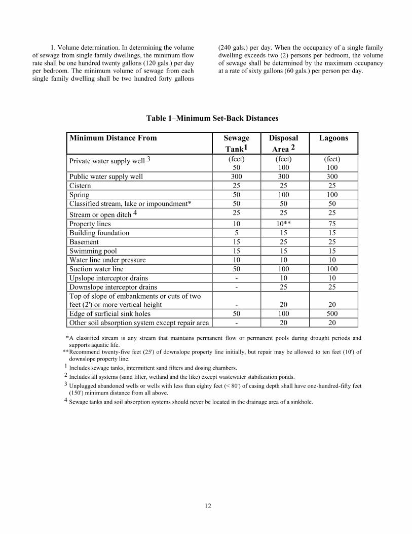
(D) Minimum Set-Back Distances. All on-site
wastewater treatment and disposal systems shall be located
in accordance with the distances shown in Table 1.
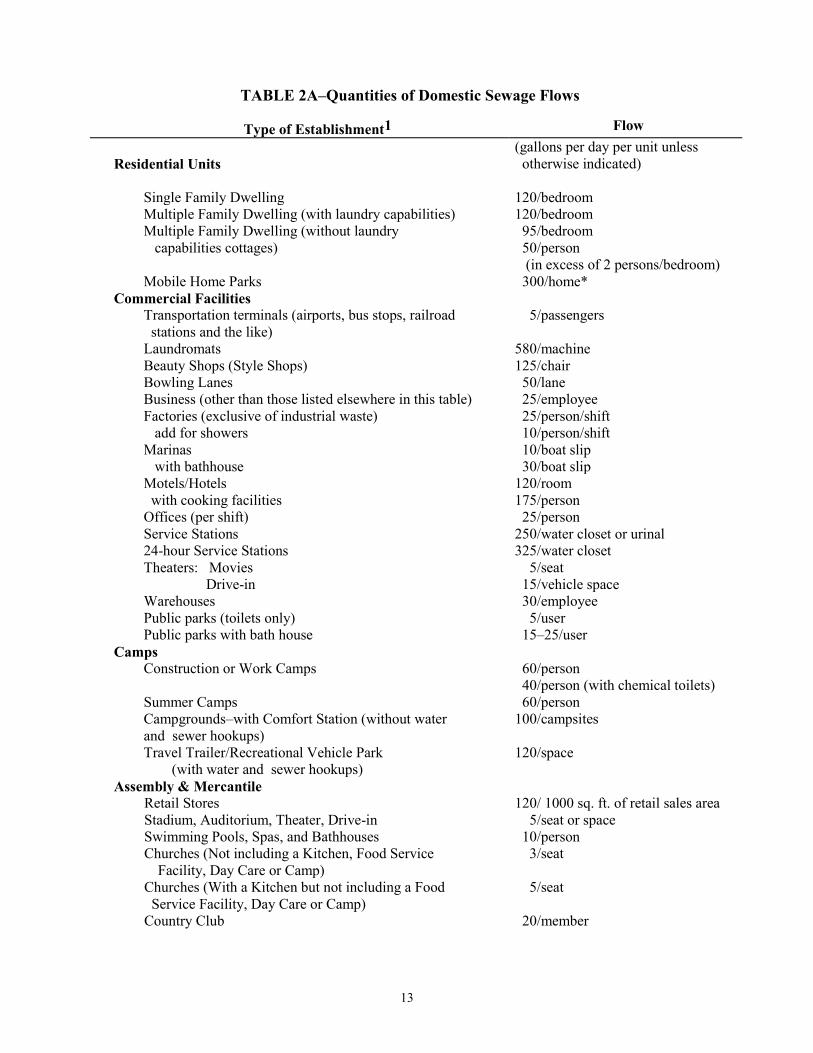
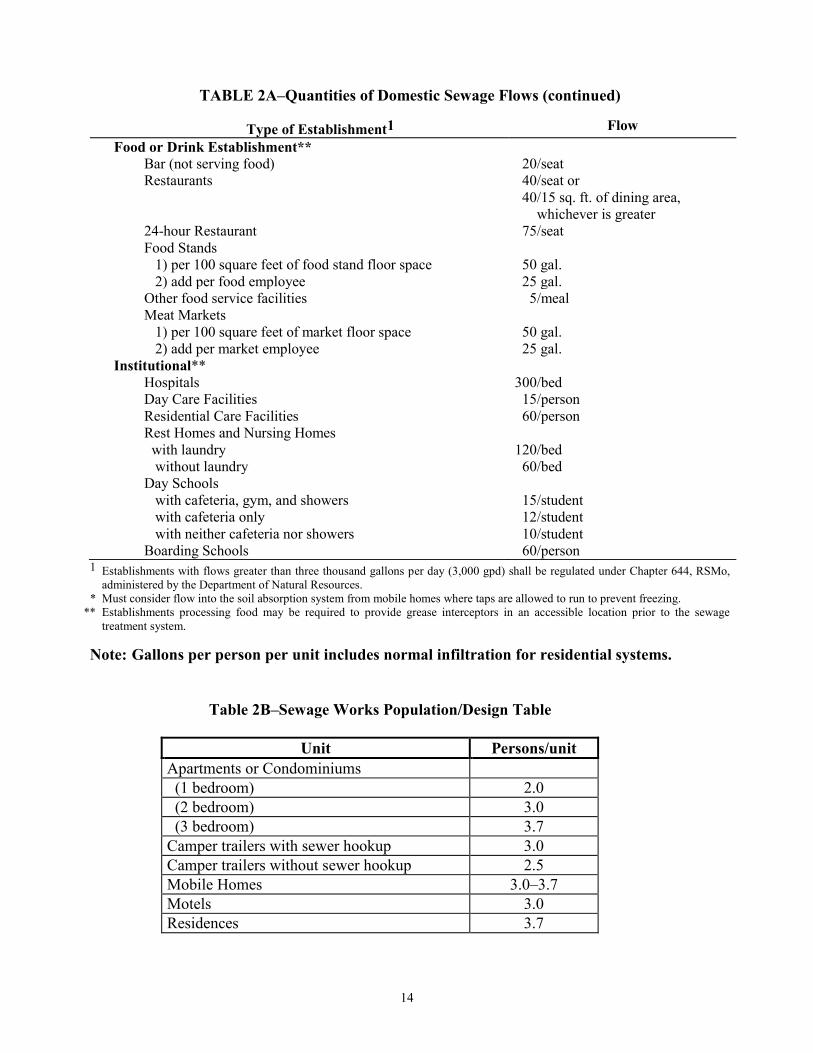
(E) Sewage Flow Rates. Table 2A or 2B shall be used to
determine the minimum design daily flow of sewage
required in calculating the design volume of sanitary sewage
systems to serve selected types of establishments. The
minimum design volume of sewage from any establishment
shall be one hundred gallons (100 gals.) per day. Design of
sewage treatment and disposal systems for establishments
not identified in this rule shall be determined using available
flow data, water-using fixtures, occupancy or operation
patterns and other measured data.
12
1. Volume determination. In determining the volume
of sewage from single family dwellings, the minimum flow
rate shall be one hundred twenty gallons (120 gals.) per day
per bedroom. The minimum volume of sewage from each
single family dwelling shall be two hundred forty gallons
(240 gals.) per day. When the occupancy of a single family
dwelling exceeds two (2) persons per bedroom, the volume
of sewage shall be determined by the maximum occupancy
at a rate of sixty gallons (60 gals.) per person per day.
Table 1–Minimum Set-Back Distances
Minimum Distance From Sewage
Tank1
Disposal
Area 2
Lagoons
Private water supply well 3 (feet)
50
(feet)
100
(feet)
100
Public water supply well 300 300 300
Cistern 25 25 25
Spring 50 100 100
Classified stream, lake or impoundment* 50 50 50
Stream or open ditch 4 25 25 25
Property lines 10 10** 75
Building foundation 5 15 15
Basement 15 25 25
Swimming pool 15 15 15
Water line under pressure 10 10 10
Suction water line 50 100 100
Upslope interceptor drains - 10 10
Downslope interceptor drains - 25 25
Top of slope of embankments or cuts of two
feet (2') or more vertical height
-
20
20
Edge of surficial sink holes 50 100 500
Other soil absorption system except repair area - 20 20
* A classified stream is any stream that maintains permanent flow or permanent pools during drought periods and
supports aquatic life.
** Recommend twenty-five feet (25') of downslope property line initially, but repair may be allowed to ten feet (10') of
downslope property line.
1 Includes sewage tanks, intermittent sand filters and dosing chambers.
2 Includes all systems (sand filter, wetland and the like) except wastewater stabilization ponds.
3 Unplugged abandoned wells or wells with less than eighty feet (< 80') of casing depth shall have one-hundred-fifty feet
(150') minimum distance from all above.
4 Sewage tanks and soil absorption systems should never be located in the drainage area of a sinkhole.
13
TABLE 2A–Quantities of Domestic Sewage Flows
Type of Establishment1 Flow
Residential Units
(gallons per day per unit unless
otherwise indicated)
Single Family Dwelling 120/bedroom
Multiple Family Dwelling (with laundry capabilities) 120/bedroom
Multiple Family Dwelling (without laundry
capabilities cottages)
95/bedroom
50/person
(in excess of 2 persons/bedroom)
Mobile Home Parks 300/home*
Commercial Facilities
Transportation terminals (airports, bus stops, railroad
stations and the like)
5/passengers
Laundromats 580/machine
Beauty Shops (Style Shops) 125/chair
Bowling Lanes 50/lane
Business (other than those listed elsewhere in this table) 25/employee
Factories (exclusive of industrial waste)
add for showers
25/person/shift
10/person/shift
Marinas
with bathhouse
10/boat slip
30/boat slip
Motels/Hotels
with cooking facilities
120/room
175/person
Offices (per shift) 25/person
Service Stations 250/water closet or urinal
24-hour Service Stations 325/water closet
Theaters: Movies
Drive-in
5/seat
15/vehicle space
Warehouses 30/employee
Public parks (toilets only) 5/user
Public parks with bath house 15–25/user
Camps
Construction or Work Camps 60/person
40/person (with chemical toilets)
Summer Camps 60/person
Campgrounds–with Comfort Station (without water
and sewer hookups)
100/campsites
Travel Trailer/Recreational Vehicle Park
(with water and sewer hookups)
120/space
Assembly & Mercantile
Retail Stores 120/ 1000 sq. ft. of retail sales area
Stadium, Auditorium, Theater, Drive-in 5/seat or space
Swimming Pools, Spas, and Bathhouses 10/person
Churches (Not including a Kitchen, Food Service
Facility, Day Care or Camp)
3/seat
Churches (With a Kitchen but not including a Food
Service Facility, Day Care or Camp)
5/seat
Country Club 20/member
14
TABLE 2A–Quantities of Domestic Sewage Flows (continued)
Type of Establishment1 Flow
Food or Drink Establishment**
Bar (not serving food) 20/seat
Restaurants 40/seat or
40/15 sq. ft. of dining area,
whichever is greater
24-hour Restaurant 75/seat
Food Stands
1) per 100 square feet of food stand floor space 50 gal.
2) add per food employee 25 gal.
Other food service facilities 5/meal
Meat Markets
1) per 100 square feet of market floor space 50 gal.
2) add per market employee 25 gal.
Institutional**
Hospitals 300/bed
Day Care Facilities 15/person
Residential Care Facilities 60/person
Rest Homes and Nursing Homes
with laundry 120/bed
without laundry 60/bed
Day Schools
with cafeteria, gym, and showers 15/student
with cafeteria only 12/student
with neither cafeteria nor showers 10/student
Boarding Schools 60/person 1 Establishments with flows greater than three thousand gallons per day (3,000 gpd) shall be regulated under Chapter 644, RSMo,
administered by the Department of Natural Resources.
* Must consider flow into the soil absorption system from mobile homes where taps are allowed to run to prevent freezing.
** Establishments processing food may be required to provide grease interceptors in an accessible location prior to the sewage
treatment system.
Note: Gallons per person per unit includes normal infiltration for residential systems.
Table 2B–Sewage Works Population/Design Table
Unit Persons/unit
Apartments or Condominiums
(1 bedroom) 2.0
(2 bedroom) 3.0
(3 bedroom) 3.7
Camper trailers with sewer hookup 3.0
Camper trailers without sewer hookup 2.5
Mobile Homes 3.0–3.7
Motels 3.0
Residences 3.7

15
2. Other establishments. For establishments or
housing developments other than a single family residence,
either Table 2A shall be used to estimate the sewage flow
rate or actual measured flow rate for existing systems may
be used. Values for estimated sewage flow for
establishments having food service operations shall be
increased by a factor of one and one-half (1.5) to
compensate for the high organic strength. Grease traps shall
be required at food service facilities, meat markets and
other places of business where the accumulation of grease
or oils can cause premature failure of a soil absorption
system. The following design criteria shall be met:
A. The grease trap shall conform to Plumbing &
Drainage Institute Standard PDI-G101 or equivalent;
B. The grease trap shall be plumbed to receive all
wastes associated with food handling and no toilet wastes;
C. The grease trap liquid capacity shall be
sufficient to provide for at least five gallons (5 gals.) of
storage per meal served per day, at least two-thirds (2/3) of
the required septic tank liquid capacity, or a capacity as
determined in accordance with the following:
LC = D x GL x ST x HR/2 x LF
where LC = grease trap liquid capacity (gallons)
D = number of seats in dining area
GL = gallons of wastewater per meal
(1.5 single-service; 2.5 full-service)
ST = storage capacity factor = 2.5
HR = number of hours open
LF = loading factor = (1.25 interstate highway
= 1.0 other highways and
recreational areas
= 0.8 secondary roads); D. Two (2) or more chambers must be provided,
with total length-to-width ratio at least two to one (2:1).
Chamber opening and outlet sanitary tee must extend down
at least fifty percent (50%) of the liquid depth;
E. Access manholes, with a minimum diameter of
twenty-four inches (24"), shall be provided over each
chamber and sanitary tee. The access manholes shall extend
at least to finished grade and be designed and maintained to
prevent surface water infiltration. The manholes shall also
have readily removable covers to facilitate inspection and
grease removal; and
F. Where it has been demonstrated that specially
designed grease interceptors will provide improved
performance, the grease trap liquid capacity may be
reduced by up to fifty percent (50%).
3. Population to be served. Unless satisfactory
justification can be given for using lower per-unit
occupancies, the figures in Table 2B shall be used in
determining the population for which to design the sewage
works:
4. Reduction in sewage flow. Reductions in design
sewage flow rates may be allowed by the administrative
authority on a case-by-case basis depending upon water
conservation plans. Sewage flow rates may be reduced up
to forty percent (40%) for gray water systems where the
toilet wastes are discharged to a holding tank and disposed
of off site or where waterless toilets are utilized.
(2) Site Evaluation. (A) All proposed sites for on-site sewage treatment and
disposal systems shall be evaluated for the following:
1. Either percolation tests or soil conditions,
properties and permeability as determined by a soil
morphology examination; a profile pit shall be required for
all new installations in order to conduct soil morphology
examination;
2. Slope;
3. The existence of lowlands, local surface
depressions, rock outcrops and sinkholes;
4. All required setback distances as required in
subsection (1)(D) of this rule;
5. Surface water flooding probability and depth to
water table;
6. Location of easements and underground utilities;
7. Amount of available area for the installation of the
system and an area for replacement;
8. Location of homesite or dwelling as well as
management of surface runoff water from those buildings;
9. Any other cultural feature, such as roads, streets
and the like in the surrounding areas which influences
surface and subterrainal flow of water on or near the
proposed site; and
10. Any significant groundwater contamination
potential.
(B) Preliminary Soils Information. During a site
evaluation reference may be made of county soil survey
reports which are available from the United States
Department of Agriculture (USDA) Natural Resources
Conservation Service (NRCS) for a majority of the counties
in Missouri. NRCS soil survey reports should not be used
as sole final determination for a specific site, but only as a
guide to which soils are expected in a given area.
(C) Soil Permeability and Soil Percolation. Soil
permeability and soil percolation are two (2) different soil
features with no direct correlation.
1. Soil permeability is that quality that enables soil
to transmit water or air. It can be measured quantitatively in
terms of rate of flow of water through a unit cross section
of saturated soil in unit time under specified temperature
and hydraulic conditions.
2. Soil percolation rate is based on a standard
method which includes a twenty-four (24)-hour presoak in
a six to eight inch (6–8") diameter hole to the depth of the
proposed absorption field. After the presoak, water is
poured into the hole to a level of eight inches (8") above
the bottom. The drop in water level is then measured at
thirty (30)-minute intervals until a stabilized rate is
16
obtained. Results are recorded as minutes per inch
(min./in.) for the water level to drop.
(D) Procedures for Percolation Tests and Profile Holes.
Two (2) types of site evaluations are acceptable. Each type
depends upon the technical expertise of the individual
conducting the evaluations. When percolation tests are
slower than sixty minutes per inch (60 min./in.), the design
must be drafted and signed by a registered engineer unless
site suitability and system sizing has been determined by
soil evaluation in accordance with section (7) of this rule.
This would apply to all systems except for lagoons or other
systems that do not use the soil for treatment. When
percolation tests are slower than one hundred and twenty
minutes per inch (120 min./in.), on-site sewage disposal
systems shall not be permitted, except for lagoons or other
systems designed in accordance with sections (6) and (7) of
this rule. The administrative authority will determine which
method(s) is to be used. The types of site evaluations are
described as follows:
1. Percolation tests only. This type of site evaluation
is where site suitability and sizing of the soil absorption
system is made by percolation tests and there is no other
evaluation of soil characteristics. This type of site
evaluation can be used only for siting and sizing standard
systems in areas which are not classified as having
significant groundwater contamination potential. When
using this type of evaluation, only percolation rates
between ten minutes and sixty minutes per inch (10–60
min./in.) will be acceptable. Percolation tests shall be
conducted by an engineer, sanitarian, registered geologist,
soil scientist or a person who has been trained and certified
by the Department of Health in accordance with section
701.040(2), RSMo. These tests shall be performed in
accordance with the following procedure:
A. A minimum of four (4) percolation test holes
are required with three (3) of the holes around the periphery
within the proposed soil absorption site and one (1) in the
middle of the proposed soil absorption site;
B. Each test hole shall be six to eight inches (6–
8") in diameter, have vertical side walls and be bored or
dug to a depth of the bottom of the proposed soil absorption
system;
C. The bottom and sides of the hole shall be
carefully scratched to remove any smearing and to provide
a natural soil surface into which water may penetrate. All
loose material shall be removed from the bottom of the test
hole and two inches (2") of one-fourth to three-fourths inch
(1/4–3/4") washed gravel shall be added to protect the
bottom from scouring;
D. The hole shall be carefully filled with clear
water to a minimum of twelve inches (12") over the soil
bottom of the test hole and maintained for no less than four
(4) hours. The hole shall then be allowed to swell for at
least twenty-four (24) hours. In sandy soils, the saturation
and swelling procedure shall not be required and the test
may proceed if one (1) filling of the hole has seeped away
in less than ten (10) minutes;
E. In sandy soils, the water depth shall be
adjusted to eight inches (8") over the soil bottom of the test
hole. From a fixed reference point, the drop in water level
shall be measured in inches to the nearest one-eighth inch
(1/8") at approximately ten (10)-minute intervals. A
measurement can also be made by determining the time it
takes for the water level to drop one inch (1") from an
eight-inch (8") reference point. If eight inches (8") of water
seeps away in less than ten (10) minutes, a shorter interval
between measurements shall be used but in no case shall
the water depth exceed eight inches (8"). The test shall
continue until three (3) consecutive percolation rate
measurements vary by a range of no more than ten percent
(10%);
F. In other soils, the water depth shall be adjusted
to eight inches (8") over the soil at the bottom of the test
hole. From a fixed reference point, the drop in water level
shall be measured in inches to the nearest one-eighth inch
(1/8") at approximately thirty (30)-minute intervals,
refilling between measurements to maintain an eight-inch
(8") starting head. The test shall continue until three (3)
consecutive percolation rate measurements vary by a range
of no more than ten percent (10%). The percolation rate can
also be made by observing the time it takes the water level
to drop one inch (1") from an eight-inch (8") reference
point if a constant water depth of at least eight inches (8")
has been maintained for at least four (4) hours prior to the
measurement;
G. Percolation rate shall be calculated as follows:
(I) The time interval shall be divided by the
drop in water level to obtain the percolation rate in minutes
per inch;
(II) The slowest percolation rate of the four (4)
tests shall be used to determine the final soil treatment
system design. Where the slowest percolation rate varies by
more than twenty minutes per inch (20 min./in.) from the
other tests, a detailed soils morphology evaluation must be
conducted to justify a design based upon the average
percolation rate; and
(III) For reporting the percolation rate,
worksheets showing all calculations and measurements
shall be submitted; and
H. Depth to bedrock or other restrictive layer
shall be determined in areas where it is known that bedrock
may exist at depths less than ten feet (10'); and
2. Soil Morphology. This evaluation shall be
conducted by a soil scientist unless an engineer, registered
geologist or sanitarian has had special training and field
experience to determine the required soil characteristics.
This type of evaluation is recommended for sites that are
classified as having significant groundwater contamination
potential, severe geological limitations or severe limitations
relating to restrictive layers. Section (7) of this rule
contains criteria for this type of site evaluation. Since this
type of soil analysis pertains to the factors that relate

17
directly to permeability, no percolation test is required,
however the administrative authority may retain the option
of requiring percolation tests for additional information in
determining site suitability.
(3) Building Sewers. Building sewers used to conduct wastewater from a
building to an on-site wastewater treatment and disposal
system shall be constructed of material meeting the
minimum requirements of American Society for Testing
and Materials (ASTM) Standards and listed by that agency
for such use. Suitable materials meeting ASTM standards
include: Acrylonitrile, butadiene styrene (ABS), cast iron
pipe, concrete pipe, copper or copper-alloy tubing,
polyvinyl chloride (PVC) or vitrified clay pipe. Although
listed by ASTM, asbestos cement pipe will not be accepted
due to potential health hazards to installers. Building sewer
specifications are as follows:
(A) Size. Building sewers shall not be less than four
inches (4") in diameter;
(B) Slope. Building sewers shall be laid to the following
minimum slope:
1. Four-inch (4") sewer–twelve inches (12") per one
hundred feet (100'); and
2. Six-inch (6") sewer–eight inches (8") per one
hundred feet (100');
(C) Cleanouts. A cleanout shall be provided at least
every one hundred feet (100') and at every change in
direction or slope if the change exceeds forty-five degrees
(45°). A cleanout should be provided between house and
tank; and
(D) Connection to sewage tank. The pipe going into
and out of the sewage tank shall be schedule 40 PVC or
cast iron and shall extend a minimum of two feet (2')
beyond the hole of excavation for the sewage tank.
(4) Sewage Tanks. (A) General. All liquid waste and washwater with the
following exceptions shall discharge into the sewage tank.
Roof, garage, footing, surface water, drainage, cooling
water discharges and hazardous wastes shall be excluded
from the sewage tank. Backwash from water softeners and
swimming pool filtration systems may be excluded from
the sewage tank. In such event of excluding swimming
pool filter backwash, the Department of Natural Resources
shall be contacted for applicability of a discharge permit.
All sewage tank effluent shall be discharged to a soil
absorption system that is designed to retain the effluent
upon the property from which it originated. All tanks
regardless of material or method of construction shall-
1. Be watertight and designed and constructed to
withstand all lateral earth pressures under saturated soil
conditions with the tank empty;
2. Be designed and constructed to withstand a
minimum of two feet (2') of saturated earth cover above the
tank top; and
3. Not be subject to excessive corrosion or decay.
Metal sewage tanks shall not be used unless specifically
allowed by the administrative authority on a case-by-case
basis. The tank shall be thoroughly coated inside and out
with a bituminous or other suitable coating. Any damage to
the bituminous coating shall be repaired by recoating.
Table 3–Tank Capacity
Tank Design and Capacity
Minimum
guage
thickness
Minimum
Diameter
Vertical cylindrical 500 thru 1000 gallons bottom and sidewalls
(guage)
14
(inches)
None
cover 12
baffle 12
1001 thru 1250 gallons complete tank 10 None
1251 thur 1500 gallons complete tank
7 None
Horizonital cylindrical
500 thru 1000 gallons complete tank
13
54
1001 thru 1500 gallons complete tank 12 64
1501 thru 2500 gallons complete tank 10 76
2501 thru 6000 gallons complete tank
7 76
18
Additionally, plastic sanitary tees shall be used for the
inlet and outlet for the sewage tank. The administrative
authority shall use Table 3 regarding minimum gauge
thickness for metal sewage tanks.
(B) Septic Tanks. Septic tanks, regardless of material
or method of construction, shall conform to the following
criteria:
1. The liquid depth of any septic tank or its
compartment shall be not less than thirty-six inches (36").
A liquid depth greater than six and one-half feet (6 1/2')
shall not be considered in determining tank capacity;
2. No tank or compartment shall have an inside
horizontal dimension less than twenty-four inches (24");
3. Inlet and outlet connections of the tank shall be
protected by baffles or sanitary tees as defined in
paragraph (4)(B)6. of this rule;
4. The space in the tank between the liquid surface
and the top of the inlet and outlet baffles shall not be less
than twenty percent (20%) of the total required capacity,
except that in horizontal cylindrical tanks, this space shall
be not less than fifteen percent (15%) of the total required
liquid capacity;
5. Inlet and outlet baffles shall be constructed of
acid-resistant concrete, acid-resistant fiberglass or plastic;
6. Sanitary tees shall be affixed to the inlet or outlet
pipes with a permanent waterproof adhesive. Baffles shall
be integrally cast with the tank, affixed with a permanent
waterproof adhesive or with stainless steel connectors top
and bottom;
7. The inlet baffle shall extend at least six inches
(6") but no more than twenty percent (20%) of the total
liquid depth below the liquid surface and at least one inch
(1") above the crown of the inlet sewer;
8. The outlet baffle and the baffles between
compartments shall extend below the liquid surface a
distance equal to forty percent (40%) of the liquid depth,
except that the penetration of the indicated baffles or
sanitary tees for horizontal cylindrical tanks shall be thirty-
five percent (35%) of the total liquid depth. They also shall
extend above the liquid surface as required in paragraph
(4)(B)4. of this rule. In no case shall they extend less than
six inches (6") above the liquid surface;
9. There shall be at least one inch (1") between the
underside of the top of the tank and the highest point of the
inlet and outlet devices;
10. The inlet shall be not less than three inches (3")
above the outlet;
11. The inlet and outlet shall be located opposite
each other along the axis of maximum dimension. The
horizontal distance between the nearest points of the inlet
and outlet devices shall be at least four feet (4');
12. Sanitary tees shall be at least four inches (4") in
diameter. Inlet baffles shall be no less than six inches (6")
or no more than twelve inches (12") measured from the
end of the inlet pipe to the nearest point on the baffle.
Outlet baffles shall be six inches (6") measured from
beginning of the outlet pipe to the nearest point on the
baffle;
13. Access to the septic tank shall be as follows:
A. Manholes. Access shall be provided over both
the inlet and outlet devices and to each tank compartment
by means of either a removable cover or a manhole. Where
the top of the tank is located more than eighteen inches
(18") below the finished grade, manholes and inspection
holes shall extend to approximately eight inches (8")
below the finished grade. The extension can be made using
riser of approved material and fitted with tight covers of
heavy metal or concrete. Proper attention must be given to
the accident hazard involved when manholes are extended
close to the ground surface. Manhole risers are not
required when the top of the tank is within eighteen inches
(18") of final grade. All manhole openings must be
provided with a substantial, fitted, water-tight cover of
concrete, cast iron or other approved material. All manhole
covers which terminate below grade shall be covered with
at least six inches (6") of earth. Manhole covers which
terminate above grade shall have either an effective
locking device or otherwise be adequately sealed in a
manner to prevent accidental access; and
B. A six-inch (6") inspection port shall be
provided over the inlet and outlet baffles of each tank and
terminate at or above grade. An inspection port shall not
be used as a pumpout access. A manhole cover at or
above grade may also serve in place of inspection ports;
14. Compartmentation of single tanks shall be in
accordance with the following:
A. Septic tanks larger than fifteen hundred
gallons (1500 gals.) and fabricated as a single unit shall be
divided into two (2) or more compartments;
B. When a septic tank is divided into two (2)
compartments, not less than one-half (1/2), nor more than
two-thirds (2/3), of the total volume shall be in the first
compartment;
C. When a septic tank is divided into three (3) or
more compartments, one-half (1/2) of the total volume
shall be in the first compartment and the other half equally
divided in the other compartments;
D. Connections between compartments shall be
baffled so as to obtain effective retention of scum and
sludge. The submergence of the inlet and outlet baffles of
each compartment shall be as specified in paragraphs
(4)(B)7. and 8. of this rule;
E. Adequate venting shall be provided between
compartments by baffles or by an opening of at least fifty
(50) square inches near the top of the compartment wall;
and
F. Adequate access to each compartment shall be
provided by one (1) or more manholes with a minimum
opening twenty inches (20") square or in diameter and
located within six feet (6') of all walls of the tank;
15. The use of multiple tanks shall conform with the
following:
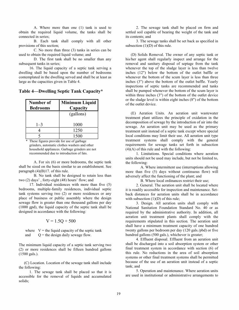
19
A. Where more than one (1) tank is used to
obtain the required liquid volume, the tanks shall be
connected in series;
B. Each tank shall comply with all other
provisions of this section;
C. No more than three (3) tanks in series can be
used to obtain the required liquid volume; and
D. The first tank shall be no smaller than any
subsequent tanks in series;
16. The liquid capacity of a septic tank serving a
dwelling shall be based upon the number of bedrooms
contemplated in the dwelling served and shall be at least as
large as the capacities given in Table 4.
Table 4—Dwelling Septic Tank Capacity*
Number of
Bedrooms
Minimum Liquid
Capacity
1–3
(gallons)
1000
4 1250
5 1500 * These figures provide for use of garbage
grinders, automatic clothes washers and other
household appliances. Garbage grinders are not
recommended due to introduction of fats.
A. For six (6) or more bedrooms, the septic tank
shall be sized on the basis similar to an establishment. See
paragraph (4)(B)17. of this rule.
B. No tank shall be designed to retain less than
two (2) days’ , forty-eight (48) hours’ flow; and
17. Individual residences with more than five (5)
bedrooms, multiple-family residences, individual septic
tank systems serving two (2) or more residences or any
place of business or public assembly where the design
sewage flow is greater than one thousand gallons per day
(1000 gpd), the liquid capacity of the septic tank shall be
designed in accordance with the following:
V = 1.5Q + 500
where V = the liquid capacity of the septic tank
and Q = the design daily sewage flow. The minimum liquid capacity of a septic tank serving two
(2) or more residences shall be fifteen hundred gallons
(1500 gals.).
(C) Location. Location of the sewage tank shall include
the following:
1. The sewage tank shall be placed so that it is
accessible for the removal of liquids and accumulated
solids;
2. The sewage tank shall be placed on firm and
settled soil capable of bearing the weight of the tank and
its contents; and
3. The sewage tanks shall be set back as specified in
subsection (1)(D) of this rule.
(D) Solids Removal. The owner of any septic tank or
his/her agent shall regularly inspect and arrange for the
removal and sanitary disposal of septage from the tank
whenever the top of the sludge layer is less than twelve
inches (12") below the bottom of the outlet baffle or
whenever the bottom of the scum layer is less than three
inches (3") above the bottom of the outlet baffle. Yearly
inspections of septic tanks are recommended and tanks
shall be pumped whenever the bottom of the scum layer is
within three inches (3") of the bottom of the outlet device
or the sludge level is within eight inches (8") of the bottom
of the outlet device.
(E) Aeration Units. An aeration unit wastewater
treatment plant utilizes the principle of oxidation in the
decomposition of sewage by the introduction of air into the
sewage. An aeration unit may be used as the primary
treatment unit instead of a septic tank except where special
local conditions may limit their use. All aeration unit type
treatment systems shall comply with the general
requirements for sewage tanks set forth in subsection
(4)(A) of this rule and with the following:
1. Limitations. Special conditions where aeration
units should not be used may include, but not be limited to,
the following:
A. Where intermittent use (interruptions allowing
more than five (5) days without continuous flow) will
adversely affect the functioning of the plant; and
B. Where local ordinances restrict their use;
2. General. The aeration unit shall be located where
it is readily accessible for inspection and maintenance. Set-
back distances for aeration units shall be in accordance
with subsection (1)(D) of this rule;
3. Design. All aeration units shall comply with
National Sanitation Foundation Standard No. 40 or as
required by the administrative authority. In addition, all
aeration unit treatment plants shall comply with the
requirements stipulated in this section. The aeration unit
shall have a minimum treatment capacity of one hundred
twenty gallons per bedroom per day (120 gals./pbd) or five
hundred gallons (500 gals.), whichever is greater;
4. Effluent disposal. Effluent from an aeration unit
shall be discharged into a soil absorption system or other
final treatment system in accordance with section (6) of
this rule. No reductions in the area of soil absorption
systems or other final treatment systems shall be permitted
because of the use of an aeration unit instead of a septic
tank; and
5. Operation and maintenance. Where aeration units
are used in institutional or administrative arrangements to
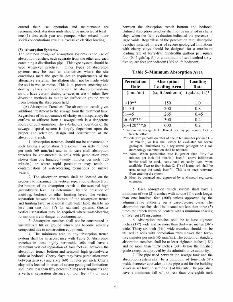
20
control their use, operation and maintenance are
recommended. Aeration units should be inspected at least
one (1) time each year and pumped when mixed liquor
solids concentrations result in excessive clarifier loading.
(5) Absorption Systems. The common design of absorption systems is the use of
absorption trenches, each separate from the other and each
containing a distribution pipe. This type system should be
used whenever practical. Other types of absorption
systems may be used as alternatives where the site
conditions meet the specific design requirements of the
alternative systems. Installation shall not be made while
the soil is wet or moist. This is to prevent smearing and
destroying the structure of the soil. All absorption systems
should have curtain drains, terraces or use of other flow
diversion methods to minimize surface or ground water
from loading the absorption field.
(A) Absorption Trenches. The absorption trench gives
additional treatment to the sewage from the treatment tank.
Regardless of its appearance of clarity or transparency, the
outflow or effluent from a sewage tank is a dangerous
source of contamination. The satisfactory operation of the
sewage disposal system is largely dependent upon the
proper site selection, design and construction of the
absorption trench.
1. Absorption trenches should not be constructed in
soils having a percolation rate slower than sixty minutes
per inch (60 min./in.) and in no case shall absorption
trenches be constructed in soils with percolation rates
slower than one hundred twenty minutes per inch (120
min./in.) or where rapid percolation may result in
contamination of water-bearing formations or surface
waters.
2. The absorption trench shall be located on the
property to maximize the vertical separation distance from
the bottom of the absorption trench to the seasonal high
groundwater level, as determined by the presence of
mottling, bedrock or other limiting layer. The vertical
separation between the bottom of the absorption trench
and limiting layer or seasonal high water table shall be no
less than one foot (1') for standard systems. Greater
vertical separation may be required where water-bearing
formations are in danger of contamination.
3. Absorption trenches shall not be constructed in
unstabilized fill or ground which has become severely
compacted due to construction equipment.
4. The minimum area in any absorption trench
system shall be in accordance with Table 5. Absorption
trenches in these highly permeable soils shall have a
minimum vertical separation of four feet (4') between the
absorption trench bottom and seasonal high groundwater
table or bedrock. Cherty clays may have percolation rates
between zero (0) and sixty (60) minutes per inch. Cherty
clay soils located in areas of severe geological limitations
shall have less than fifty percent (50%) rock fragments and
a vertical separation distance of four feet (4') or more
between the absorption trench bottom and bedrock.
Unlined absorption trenches shall not be installed in cherty
clays when the field evaluation indicated the presence of
large voids. Regardless of the percolation rate, absorption
trenches installed in areas of severe geological limitations
with cherty clays should be designed for a maximum
loading rate of forty-five hundredths gallons per square
foot (0.45 gals/sq. ft.) or a minimum of two hundred sixty-
five square feet per bedroom (265 sq. ft./bedroom).
Table 5–Minimum Absorption Area
Percolation
Rate
Absorption
Loading Area
Loading
Rate
(min./in.)
<10**
(sq.ft./bedroom)
150
(gal./sq. ft.)*
1.0
11–30 200 0.8
31–45 265 0.45
46–60*** 300 0.4
61–120***Æ 600 0.2 * Gallons of sewage tank effluent per day per square foot of
trench bottom.
** Soils with percolation rates of one to ten minutes per inch (1–
10 min./in.) or less shall either be evaluated for severe
geological limitations by a registered geologist or a soil
morphology examination shall be required.
*** Note: When percolation rate is greater than forty-five
minutes per inch (45 min./in.), backfill above infiltration
barrier shall be sand, loamy sand or sandy loam, when
available. Two to four inches (2–4") of loamy soil shall be
used to cap the sandy backfill. This is to keep rainwater
from entering the system.
Æ Must be designed and approved by a Missouri registered
engineer.
5. Each absorption trench system shall have a
minimum of two (2) trenches with no one (1) trench longer
than one hundred feet (100') unless approved by the
administrative authority on a case-by-case basis. The
absorption trenches shall be located not less than three (3)
times the trench width on centers with a minimum spacing
of five feet (5') on centers.
6. Absorption trenches shall be at least eighteen
inches (18") wide and no more than thirty-six inches (36")
wide. Thirty-six inch (36") wide trenches should not be
utilized in soils with percolation rates slower than forty-
five minutes per inch (45 min./in.). The bottom of standard
absorption trenches shall be at least eighteen inches (18")
and no more than thirty inches (30") below the finished
grade except as approved by the administrative authority.
7. The pipe used between the sewage tank and the
absorption system shall be a minimum of four-inch (4")
inside diameter equivalent to the pipe used for the building
sewer as set forth in section (3) of this rule. The pipe shall
have a minimum fall of not less than one-eighth inch
21
(1/8") per foot. All joints shall be of watertight
construction.
8. Gravity-fed absorption field distribution lines
should be at least four inches (4") in diameter. Perforated
distribution line shall have holes at least one-half inch
(1/2") and no more than three-fourths inch (3/4") in
diameter.
A. Pipe used for distribution lines shall meet the
appropriate ASTM standard or those of an equivalent
testing laboratory. Fittings used in the absorption field
shall be compatible with the materials used in the
distribution lines.
B. When four inch (4")- or six inch (6")-diameter
corrugated plastic tubing is used for distribution lines, it
shall be certified as complying with applicable ASTM
standards. The corrugated tubing shall have either two (2)
or three (3) rows of holes, each hole between one-half inch
(1/2") and three-fourths inch (3/4") in diameter and spaced
longitudinally approximately four inches (4") on centers.
Coiled tubing shall not be used.
9. The absorption trenches shall be constructed as
level as possible, but in no case shall the fall in a single
trench bottom exceed one-fourth inch (1/4") in ten feet
(10'). The ends of distribution lines should be capped or
plugged, or when they are at equal elevations, they shall be
connected.
10. Rock used in soil absorption systems shall be
clean gravel or crushed stone, and graded or sized between
one and one-half and three inches (1 1/2-3") with no more
than ten percent (10%) material to pass through a one-half
inch (1/2") screen. The rock shall be placed a minimum of
twelve inches (12") deep with at least six inches (6")
below the pipe and two inches (2") over the pipe and
distributed uniformly across the trench bottom and over
the pipe. Limestone and dolomite shall be avoided when
possible. Before placing soil backfill over the trenches, the
gravel shall be covered with one (1) of the following:
A. Unfaced, rolled, three and one-half inch (3-
1/2") thick fiberglass insulation;
B. Untreated building paper;
C. Synthetic drainage fabric; or
D. Other material approved by the administrative
authority laid as to separate the gravel from the backfill.
11. Complex slope patterns and slopes dissected by
gullies shall not be considered for installation of
absorption trenches. Uniform slopes under fifteen percent
(15%) shall be considered suitable slope for installation of
absorption trenches. When slopes are less than two percent
(2%), provisions shall be made to insure adequate surface
drainage. When slopes are greater than four percent (4%),
the absorption trenches shall follow the contour of the
ground. Uniform slopes between fifteen percent (15%) and
thirty percent (30%) should not be used for installation of
absorption trenches unless the soils are three feet (3') or
more below the trench bottom. Slopes within this range
may require installation of interceptor drains upslope from
the soil absorption system to remove all excess water that
might be moving laterally through the soil during wet
periods. Usable areas larger than minimum are ordinarily
required in this slope range. Slopes greater than thirty
percent (30%) shall not be utilized for installation of
absorption trenches unless the following requirements can
be met and approval is obtained from the administrative
authority:
A. The slope can be terraced or otherwise graded
or the absorption trenches can be located in naturally
occurring soil so as to maintain a minimum ten foot (10')
horizontal distance from the absorption trench and the top
edge of the fill embankment;
B. The soil is permeable and no restrictive layers
or water tables occur at a depth within two feet (2') of the
trench bottom;
C. Surface water runoff is diverted around the
absorption trench field so that there will be no scouring or
erosion of the soil over the field or to allow surface runoff
onto the field;
D. If necessary, groundwater flow from heavy
rainfall is intercepted and diverted to prevent that water
from running into or saturating the soil absorption system;
and
E. There is sufficient ground area available to
install the absorption trench system with these
modifications.
12. Effluent distribution devices, including
distribution boxes, flow dividers and flow diversion
devices, shall be of sound construction, watertight, not
subject to excessive corrosion and of adequate design as
approved by the administrative authority. Effluent
distribution devices shall be separated from the sewage
tank by a minimum of two feet (2') of undisturbed or
compacted soil and shall be placed level on a solid
foundation of soil, gravel or concrete to prevent
differential settlement of the device. Distribution boxes
provided with flow equalizers are recommended.
A. Each distribution line shall connect
individually to the distribution box and shall be watertight.
B. The pipe connecting the distribution box to
the distribution line shall be of a watertight construction
laid on undisturbed earth.
C. No more than four (4) distribution lines
should be connected to a distribution box receiving gravity
flow unless the ground surface elevation of the lowest
trench is above the flow line elevation of the distribution
box.
13. Stepdowns or drop boxes may be used where
topography prohibits the placement of absorption trenches
on level grade. Serial distribution systems should be
limited to a separation of at least three feet (3') between the
bottom of the absorption trenches and the limiting
condition such as slow permeability or zone of seasonal
saturation as evidenced by mottling. Whenever the design
sewage flow rate requires more than seven hundred and
fifty lineal feet (750 lin. ft.) of distribution line in a
stepdown or drop-box type system, the absorption field
22
shall be divided into two (2) or more equal portions.
Stepdowns shall be constructed of two feet (2') of
undisturbed soil and constructed to a height level with the
top of the upper distribution line. The inlet to a trench
should be placed either in the center or as far as practical
from the outlet (overflow) from the same trench. Drop
boxes shall be constructed so that the inlet supply pipe is
one inch (1") above the invert of the outlet supply pipe
which is connected to the next lower drop box. The top of
the trench outlet laterals, which allow effluent to move to
the distribution lines, shall be two inches (2") below the
invert of the outlet supply line. It is recommended that
drop boxes be designed to close off the trench outlets to
provide for periods of resting when the absorption trench
becomes saturated.
14. Dosing is recommended for all systems except
serial distribution systems and shall be provided when the
design sewage flow requires more than five hundred lineal
feet (500 lin. ft.) of distribution line. When the design
sewage flow requires more than one thousand lineal feet
(1000 lin. ft.) of distribution line, the absorption field shall
be divided into two (2) equal portions and each half dosed
alternatively, not more than four (4) times per day. Dosing
may be accomplished by the use of a pump. Each side of
the system shall be dosed not more than four (4) times per
day. The volume of each dose shall be the greater of the
daily sewage volume divided by the daily dosing
frequency, or an amount equal to approximately three-
fourths (3/4) of the internal volume of the distribution lines
being dosed (approximately one-half gallon per lineal foot
(1/2 gal./lin. ft.) of four-inch (4") pipe). Whenever dosed
distribution box systems are utilized, the separation
distance between the absorption trench bottom and
limiting condition should be at least two feet (2').
15. Gravelless subsurface absorption systems may
be used as an alternative to conventional four-inch (4")
pipe placed in gravel filled trenches, however they cannot
be used in areas where conventional systems would not be
allowed due to poor permeability, high groundwater or
insufficient depth to bedrock. Design approval for these
systems may be required from the administrative authority
prior to installation and all manufacturing specifications
and installation procedures shall be closely adhered to.
Gravelless trench systems using fabric wrapped tubing
shall not be used, however, where wastes contain high
amounts of grease and oil, such as in restaurants.
A. The eight (8)-, ten (10)-, and twelve (12)-inch
(inner diameter) corrugated polyethylene tubing used in
gravelless systems shall meet the requirements of ASTM
F667, Standard Specification for Large Diameter
Corrugated Polyethylene Tubing. For purpose of
calculation, the eight-inch (8") pipe may be considered
equal to eighteen inches (18") in width of a standard
absorption trench. The ten-inch (10") pipe may be
considered equal to twenty-five inches (25") in width of a
standard absorption trench.
B. Two (2) rows of perforations shall be
provided located one hundred twenty degrees (120°) apart
along the bottom half of the tubing, each sixty degrees
(60°) from the bottom centerline. The tubing shall be
marked with a visible top location indicator one hundred
twenty degrees (120°) away from each row of holes.
Perforations shall be cleanly cut and uniformly spaced
along the length of the tubing and should be staggered so
that there is only one (1) hole in each corrugation. The
tubing shall be marked with a visible top location
indicator. All gravelless drainfield pipe shall be encased at
the point of manufacture with a filter wrap of spun-bonded
nylon, spun-bonded polypropylene or other substantially
equivalent material approved by the administrative
authority.
C. Rigid corrugated tubing shall be covered with
filter wrap at the factory and each joint shall be
immediately encased in a protective wrap that will prevent
ultraviolet light penetration which shall continue to encase
the large diameter pipe and wrap until just prior to
installation in the trench. Filter wrap encasing the tubing
shall not be exposed to sunlight (ultraviolet radiation) for
extended periods. Rocks and large soil clumps shall be
removed from backfill material prior to being used. Clayey
soils (soil group IV) shall not be used for backfill. The
near end of the large diameter pipe shall have an offset
adapter (small end opening at top) suitable for receiving
the pipe from the septic tank or distribution device and
making a mechanical joint in the trench.
D. The trench for the gravelless system shall be
dug with a level bottom. On sloping ground, the trench
should follow the contour of the ground to maintain a level
trench bottom and to ensure a minimum backfill of six
inches (6"). It is recommended that the minimum
trench width for the gravelless system be eighteen inches
(18") in friable soils to ensure proper backfill around the
bottom half of the pipe. In cohesive soils, the minimum
width of excavation should be twenty-four inches (24"). In
clay soils, it is recommended that the trench be backfilled
with sandy material, sandy loam, loam, clay loam, silt
loam or silty clay loam. The gravelless system may be
installed at a trench bottom depth of eighteen inches (18")
minimum to thirty inches (30") maximum, but a more
shallow trench bottom depth of eighteen to twenty-four
inches (18-24") is recommended. To promote equal
effluent and suspended solids distribution, the slope of the
drain pipe should be from zero to one-half inch per one
hundred feet (0–1/2 in./100 ft.).
E. A gravelless chamber may be installed based
on bottom absorption area utilizing a reduction of up to
twenty-five percent (25%) in the size of a standard gravel
absorption area based upon a soil morphology evaluation
indicating the feasibility of a reduction. However, as
described in Table 6, the maximum loading rate provided
for any particular soil group must not be exceeded when
sizing for the thirty-four inch (34") chamber. For this
purpose, the fifteen inch (15") chamber may be considered
23
equal to twenty-four inches (24") in width of a standard
absorption trench. The twenty-two inch (22") chamber
may be considered equal to twenty-eight inches (28") in
width of a standard absorption trench. The thirty-four inch
(34") chamber may be considered equal to forty-two
inches (42") in width of a standard absorption trench.
F. Installation of the chamber system shall be in
accordance with this rule except:
(I) The installation shall be made in
accordance with the manufacturer’s specifications;
(II) The side walls of trenches placed in Group
IVa soils shall be raked to open pores which were
damaged or sealed during excavation; and
(III) Chambers utilizing maximum sidewall
absorption features shall be installed per the
manufacturer’s recommendations to maximize the use of
upper soil horizons; and
G. A reduction of up to twenty-five percent
(25%) in the size of the absorption field may be allowed
based upon a soil morphology evaluation indicating the
feasibility of a reduction. However, as described in Table
6, the maximum loading rate provided for any particular
soil group must not be exceeded.
Table 6–Loading Rate for Chamber Systems*
Soil Group
Range for Chambers
(gpd/sq. ft.)
I 1.0–1.2
II 0.7–0.8
III 0.5–0.6
IVa 0.3–0.4
IVb Unsuitable
V** 0.4–0.6 * Note: All application rates are for area of trench bottoms only.
** Note: No reduction is allowed for chamber systems in Group
V soils. 16. Dosing/alternating systems are encouraged,
especially in slowly permeable soil conditions.
17. The administrative authority may permit the use
of a bed system on sites where the minimum soil
permeability is a percolation rate of forty-five minutes per
inch (45 min./in.) and essentially meeting the other
requirements of this section, and only on lots which are
limited by topography, space or other site planning
considerations. In such cases the number of square feet of
bottom area needed shall be increased by fifty percent
(50%) over what would be required for a trench system.
Distribution lines shall be at least eighteen inches (18")
from the side of the bed and shall have lines on three-foot
(3') centers and care must be taken to divert surface water
away from the bed. When the design volume of sewage
exceeds six hundred gallons (600 gals.) per day, adequate
space shall be provided to accommodate a trench system
for the absorption field. There shall be no less than a two-
foot (2') separation between the bed bottom and the
limiting layer or seasonal high water table.
(B) Possible modifications to standard absorption
systems which may be utilized to overcome selected soil
and site limitations and must be approved by the
administrative authority include the following:
1. Shallow placement of absorption trenches shall
be utilized where insufficient depth to seasonally high or
perched water table or where insufficient soil thickness
prevents the placement of conventional distribution lines
in accordance with this section. Shallow trenches shall be
designed and constructed to provide a minimum of two
feet (2') of natural soil separation between the trench
bottom and the uppermost elevation of the seasonally high
or perched water table and rock. Shallow trenches may be
constructed by placing the top of the gravel at original
ground level and covering the absorption field with loamy
soil, (sandy loam, loam, clay loam, silt loam or silty clay
loam) to a depth of eight to twelve inches (8-12") at the
center. The cover over the absorption field shall extend at
least five feet (5') beyond the edge of any trench and have
a turf grass cover established immediately after
construction. If an area is to be filled and the trenches
constructed in the fill with the bottom of the trenches in at
least six inches (6") of natural soil, the following
procedures must be followed:
A. The fill material should be of a sandy texture
with a maximum clay content of twenty percent (20%).
The fill material should not be hauled or worked wet. The
area to be filled must be protected from traffic and small
brush and trees removed prior to placement;
B. The soil surface must be loosened with a
cultivator or garden plow. This work must be done when
the soil is dry;
C. The fill is moved onto the site without driving
on the loosened soil. The fill material is then tilled into the
natural soil to create a gradual boundary between the two
(2). The remaining fill is then added in layers until the
desired height is obtained with each layer being tilled into
the preceding layer; and
D. The site is then shaped to shed water and fill
all low spots before the absorption system is installed.
After installation of the absorption system, the site must
have a turf grass cover established as soon as possible;
2. Alternating dual field absorption systems may be
utilized where soils are limited by high clogging
potentials, percolation rates slower than sixty minutes per
inch (60 min./in.) or high shrink/swell potential soils and
where the potential for malfunction and need for
immediate repair is required. Alternating dual field
absorption systems shall be designed with two (2)
complete absorption fields, each sized a minimum of
24
seventy-five percent (75%) of the total area required for a
single field and separated by an effluent flow diversion
valve. The diversion valve shall be constructed to resist
five hundred pounds (500 lbs.) crushing strength,
structurally sound and shall be resistant to corrosion. A
valve placed below ground level shall be constructed so
that it may be operated from the ground surface; and
3. Sand-lined trenches may be used in areas where
the soil has greater than fifty percent (50%) rock fragments
and there are severe geological limitations. For a
maximum loading rate of forty-five hundredths gallons per
day per square foot (.45 gpd/sq. ft.) or a minimum of two
hundred sixty-five square feet per bedroom (265 sq.
ft./bedroom), the sand is not required to meet the
requirements for intermittent sand filters. The material
must be natural or manufactured sand and have no more
than fifteen percent (15%) clay content. Manufactured
sand shall be chat, fines manufactured from igneous rocks
or chert gravel or manufactured from crushed glass.
Crushed limestone is not acceptable. For higher loading
rates, the sand must meet the requirements for an
intermittent sand filter.
A. In standard four-inch (4") pipe and gravel
trenches, the depth of liner material must be twelve inches
(12") below the gravel and at least six inches (6") on the
sides of the gravel up to the top of the gravel. To place
sand on the sides of the trenches, the trench walls must be
excavated on a slope instead of vertically. The side slopes
should be two horizontal to one vertical (2:1) and in no
case steeper than one horizontal to one vertical (1:1).
B. In gravelless pipe systems the minimum
thickness of liner material is six inches (6") around the
pipe.
C. The effluent to sand-lined systems in areas of
potential groundwater contamination should be equally
distributed as much as practically possible. Serial and
drop-box systems shall not be used. As a minimum, a
distribution box shall be used to evenly distribute the
effluent to the trenches. Dosing is recommended in order
to more positively assure even distribution.
D. The sand-lined trenches may be used, with the
approval of the administrative authority, where the
percentage of rock fragments is less than seventy percent
(70%) for at least four feet (4') below the trench bottom.
For sand-lined trenches to function properly, the
permeability of the natural material should be similar to
the permeability of the liner material. Sand-lined trenches
must not be used over fragipans or other restrictive layers
which have potential to perch water tables and could cause
saturation of the liner material.
(6) Alternative Systems. (A) General. The intent of this section is to provide
minimum standards for the design, location, installation,
use and maintenance of alternative sewage disposal
systems in areas of limiting soil characteristics, where a
standard system cannot be installed or a standard system is
not the most suitable treatment. Where these systems are
employed, they shall comply with all local codes and
ordinances and should be subject to timely inspections to
assure adherence to specifications. These systems, except
for wastewater stabilization ponds, shall be designed and
stamped by a licensed engineer. All absorption systems
should have curtain drains, terraces or use of other flow
diversion methods to minimize surface or ground water
from loading the absorption field.
(B) Adoption and Use. Where this rule is administered
by an administrative authority, those administrative
authorities may adopt this section in whole or in part as
part of a local code or ordinance. Further, nothing in this
rule or section shall require any administrative authority to
allow the installation of any system in this section.
(C) Low Pressure Pipe (LPP) System. A low pressure,
two- to four-foot (2–4') pressure head, pipe system may be
utilized where soil and site conditions prohibit the
installation of a conventional or modified septic tank
system due to the presence of shallow soil conditions,
seasonally high water table conditions and slow soil
permeability. The administrative authority may permit the
use of a LPP system where there are cherty clay soils,
severe geological limitations or both. The separation
distance in these areas of concern for groundwater
between the trench bottoms and bedrock shall be at least
four feet (4') or more. The administrative authority may
require that the hydraulic design of LPP systems be
designed by an engineer. The administrative authority may
also require the LPP trenches to be sand-lined if the soils
have severely diminished treatment capability due to
excessive rock content. The amount of rock fragments
shall be less than fifty percent (50%) and in no case more
than seventy percent (70%), unless the trenches are lined
with sand.
1. The LPP shall consist of the following basic
components:
A. A network of one- to two-inch (1–2")
diameter perforated PVC, one hundred sixty pounds per
square inch (160 lbs./sq. in.) pipe or equivalent placed in
natural soil at shallow depths, generally no more than
twelve inches (12"), in narrow trenches not less than eight
inches (8") in width and spaced not less than five feet (5')
on center. Trenches shall include at least five inches (5")
of pea gravel, if available; or if necessary, no less than
three-quarter inch (3/4") crushed stone below the pipe and
two inches (2") above the pipe; and four inches (4") of soil
cover. The holes in the perforated pipe should be spaced
from two feet (2') to no more than eight feet (8'). The
minimum hole size is five thirty-seconds inch (5/32");
B. A properly designed, two (2)-compartment
septic tank or other approved pretreatment system and a
pumping or dosing tank. The pumping or dosing tank shall
be a minimum of five hundred gallons (500 gals.) or have
the capacity to store one (1) day’s flow above the pump on
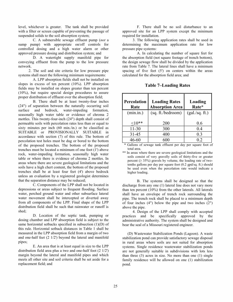
25
level, whichever is greater. The tank shall be provided
with a filter or screen capable of preventing the passage of
suspended solids to the soil absorption system;
C. A submersible sewage effluent pump (not a
sump pump) with appropriate on/off controls for
controlled dosing and a high water alarm or other
approved pressure dosing and distribution system; and
D. A watertight supply manifold pipe for
conveying effluent from the pump to the low pressure
network.
2. The soil and site criteria for low pressure pipe
systems shall meet the following minimum requirements:
A. LPP absorption fields shall not be installed on
slopes in excess of ten percent (10%). LPP absorption
fields may be installed on slopes greater than ten percent
(10%), but require special design procedures to assure
proper distribution of effluent over the absorption field;
B. There shall be at least twenty-four inches
(24") of separation between the naturally occurring soil
surface and bedrock, water-impeding formation,
seasonally high water table or evidence of chroma 2
mottles. This twenty-four-inch (24") depth shall consist of
permeable soils with percolation rates less than or equal to
sixty minutes per inch (60 min./in.) or be classified as
SUITABLE or PROVISIONALLY SUITABLE in
accordance with section (7) of this rule. The bottom of
percolation test holes must be dug or bored to the bottom
of the proposed trenches. The bottom of the proposed
trenches must be located a minimum of one foot (1') above
rock, water-impeding formation, seasonally high water
table or where there is evidence of chroma 2 mottles. In
areas where there are severe geological limitations and the
soils have a high chert content, the bottom of the proposed
trenches shall be at least four feet (4') above bedrock
unless an evaluation by a registered geologist determines
that the separation distance may be reduced;
C. Components of the LPP shall not be located in
depressions or areas subject to frequent flooding. Surface
water, perched ground water and other subsurface lateral
water movement shall be intercepted or diverted away
from all components of the LPP. Final shape of the LPP
distribution field shall be such that rainwater or runoff is
shed;
D. Location of the septic tank, pumping or
dosing chamber and LPP absorption field is subject to the
same horizontal setbacks specified in subsection (1)(D) of
this rule. Horizontal setback distances in Table 1 shall be
measured in the LPP absorption field from a margin of two
and one-half feet (2 1/2') beyond the lateral and manifold
pipes;
E. An area that is at least equal in size to the LPP
distribution field area plus a two and one-half foot (2 1/2')
margin beyond the lateral and manifold pipes and which
meets all other site and soil criteria shall be set aside for a
replacement field; and
F. There shall be no soil disturbance to an
approved site for an LPP system except the minimum
required for installation.
3. The following application rates shall be used in
determining the maximum application rate for low
pressure pipe systems:
A. In calculating the number of square feet for
the absorption field (not square footage of trench bottom),
the design sewage flow shall be divided by the application
rate from Table 7. The lateral lines shall have a minimum
spacing of five feet (5') on centers within the areas
calculated for the absorption field area; and
Table 7–Loading Rates
Percolation
Rate
Loading Rates
Absorption Area
Loading
Rate*
(min.in.)
<10**
(sq. ft./bedroom)
200
(gal./sq. ft.)
0.6
11-30 300 0.4
31-45 400 0.3
46-60 600 0.2 * Gallons of sewage tank effluent per day per square foot of
total area.
** In areas where there are severe geological limitations and the
soils consist of very gravelly soils of thirty-five or greater
percent (≥ 35%) gravels by volume, the loading rate of two-
tenths gallons per day per square foot (0.2 gpd/sq. ft.) should
be used even when the percolation rate would indicate a
higher loading.
B. The systems shall be designed so that the
discharge from any one (1) lateral line does not vary more
than ten percent (10%) from the other laterals. All laterals
shall have an envelope of trench rock surrounding the
pipe. The trench rock shall be placed to a minimum depth
of four inches (4") below the pipe and two inches (2")
above the pipe.
4. Design of the LPP shall comply with accepted
practices and be specifically approved by the
administrative authority. The system shall be designed and
bear the seal of a Missouri registered engineer.
(D) Wastewater Stabilization Ponds (Lagoon). A waste
stabilization pond can provide satisfactory sewage disposal
in rural areas where soils are not suited for absorption
systems. Single residence wastewater stabilization ponds
are not generally suitable in subdivisions with lots less
than three (3) acres in size. No more than one (1) single
family residence will be allowed on one (1) stabilization
pond.

26
1. The following minimum separation distances
may be modified as necessary to accommodate site
requirements or local codes:
A. The pond shall be located a minimum of
seventy-five feet (75') from property lines as measured
from the adjoining pond shoreline. However, this distance
must be increased where necessary to be sure that all
effluent is disposed upon the property from which it
originated;
B. The pond shall be located a minimum of two
hundred feet (200') from the nearest existing residence and
a minimum of one hundred feet (100') from the residence
that it serves;
C. The pond shall be located at least one hundred
feet (100') from a potable water supply or pump suction
line; and
D. The pond shall be located at least fifty feet
(50') from a stream, water course, lake or impoundment.
2. Ponds may be utilized when there are no
significant limitations related to groundwater from their
use and the soils have been demonstrated to be very slowly
permeable such as percolation rates slower than one
hundred twenty minutes per inch (120 min./in.). There
shall be either a minimum separation distance between the
pond bottom and creviced bedrock of three feet (3') or
installation of a clay liner with a minimum thickness of
one foot (1') or a synthetic liner, either of which must be
acceptable to the administrative authority. Percolation
losses from the pond shall not exceed one-eighth inch
(1/8") per day to prevent groundwater contamination or
nuisance conditions. Site modifications may be
accomplished to provide these soil requirements. In areas
of severe geological limitations, restrictive layers such as
fragipans shall be a minimum of twelve inches (12") thick
and shall not be breached during construction.
3. Steeply sloping areas should be avoided.
4. Selection of the pond site should consider a clear
sweep of the surrounding area by prevailing winds. Heavy
timber should be removed for a distance of fifty feet (50')
from the water’s edge to enhance wind action and prevent
shading.
5. The administrative authority may require that a
properly sized and constructed septic tank or aeration unit
precede the pond. If irrigation of the effluent is required to
maintain the wastewater on the property from which it
originated, a septic tank or aeration unit should precede the
pond. The use of a septic tank or aeration unit should not
be used as a basis for reduction of the set-back distances as
set forth in subparagraphs (6)(D)1.A.–D. of this rule.
6. The pond shall be designed on the basis of four
hundred forty square feet (440 sq. ft.) of water surface area
per bedroom at the three-foot (3') operating level. This
square footage may be reduced by a maximum of twenty
percent (20%) if a septic tank, aeration unit or other
pretreatment device precedes the pond. The minimum
water surface area at the three-foot (3') level shall be nine
hundred square feet (900 sq. ft.).
7. A single cell is generally acceptable for single
residence pond systems. If multiple cells are used for
further polishing or storing of the effluent, the secondary
cell should be one-half (1/2) the size of the primary cell.
8. The minimum embankment top width shall be
four feet (4'). The embankment slopes shall not be steeper
than three to one (3:1) on the inner and outer slopes. Inner
embankment slopes shall not be flatter than four to one
(4:1). Outer embankment slopes shall be sufficient to
prevent the entrance of surface water into the pond.
Freeboard shall be at least eighteen inches (18") and
preferably twenty-four inches (24"). Additional freeboard
may be provided.
9. To minimize erosion and facilitate weed control,
embankments shall be seeded with a locally hardy grass
from the outside toe to one foot (1') above the water line.
Alfalfa or similar long-rooted crops which might interfere
with the structure of the embankment shall not be used.
Rip rap may be necessary under unusual conditions to
provide protection of embankments from erosion.
10. The influent line shall be of a sound, durable
material of watertight construction of SDR 35 or greater.
The line shall have a minimum diameter of four inches
(4") and be laid on a firm foundation at a minimum grade
of one-eighth inch (1/8") per foot from the point of entry
into the pond. The influent line shall discharge as far as
practical from the possible outlet side of the pond. A
cleanout or manhole should be provided in the influent line
near the pond embankment. From this point the line shall
either be laid to the inner toe of the embankment and then
on the bottom of the pond to the terminus point or the line
shall be supported and secured every five feet (5'). A
concrete splash pad three feet (3') square should be placed
under the terminus of the pipe. The elevation of the
cleanout or manhole bottom should be a minimum of six
inches (6") above the high water level in the pond.
11. The pond shall be shaped so there are no narrow
or elongated portions. Round, square or rectangular cells
are considered most desirable. Rectangular cells shall have
a length not exceeding three (3) times the width. No
islands, peninsulas or coves shall be permitted.
Embankments should be rounded at corners to minimize
accumulation of floating materials.
12. The floor of the pond shall be stripped of
vegetation and leveled to the proper elevation. Organic
material removed from the pond area shall not be used in
embankment construction. The wetted area of the pond
must be sealed to prevent excessive exfiltration. Seals
consisting of soils must be adequately compacted by the
construction equipment.
13. Embankments shall be constructed of
impervious materials and compacted sufficiently to form a
stable structure with very little settlement.
14. Any effluent should be withdrawn from six
inches (6") below the water surface. This can be
accomplished by placing a tee on the inlet end of the pipe

27
or by placing the outlet pipe eight to ten inches (8-10")
lower on the inlet end than the outlet end of the pipe.
15. The pond area shall be enclosed with a fence
conforming to the following conditions:
A. The fence shall be at least four feet (4') in
height;
B. The fence shall be welded, woven or chain
link material with no smaller than fourteen gauge (14 ga.)
wire. Cattle or hog panels can be substituted with a tee
post being used for a line post;
C. Fence posts shall be pressure-treated wood,
galvanized and/or painted steel. Fence posts shall be
driven, tamped or set in concrete. Line posts should be at
least eighteen inches (18") deep and shall be spaced no
more than ten feet (10') apart. Corner posts should be at
least twenty-four inches (24") deep and shall be properly
braced;
D. The fence shall be of sound construction with
no gaps or openings along the bottom;
E. The fence shall be no closer than the center of
the berm to the water’s edge at the three-foot (3') deep
operating level. Fence set-backs should not exceed thirty
feet (30') from the water’s edge;
F. A properly hinged four foot (4') high gate or
comparable materials shall be installed and provided with
an effective latching device. The gate should be thirty-six
to forty-eight inches (36-48") in width to accommodate
maintenance and mowing equipment; and
G. The fence must be completed prior to
occupancy of the dwelling.
16. Effluent from a pond must be disposed of on the
property from which it originated. This may be
accomplished by locating the outlet as far as practical from
the property line and out of any natural drainage ditches or
swales. The minimum distance from the outlet to a
property line shall be one hundred feet (100'). Another
method is to construct a terraced swale with a minimum
length of one hundred fifty feet (150'). If these methods are
unsuccessful, or whenever there is less than twelve inches
(12") of permeable soil over a restrictive layer, controlled
surface irrigation must be used. To utilize controlled
surface irrigation, the pond must be capable of operating
up to five feet (5') deep with one foot (1') of freeboard or
have a second cell for storage. The administrative
authority shall approve the method of effluent disposal.
17. It may be necessary to introduce water into the
pond to facilitate start-up of the biological processes,
however, there shall be no permanent connection of any
roof drain, footing drain or any source of rainwater to the
wastewater stabilization pond.
18. Odor problems caused by spring turnover of
water, temporary overloading, ice cover, atmospheric
conditions or anaerobic conditions may be controlled by
broadcasting sodium or ammonium nitrate over the surface
of the pond. In general, the amount of sodium or
ammonium nitrate should not exceed two pounds (2 lbs.)
per day until the odor dissipates.
(E) Elevated Sand Mounds. Elevated sand mounds may
be considered whenever site conditions preclude the use of
absorption trenches. The construction of a mound shall be
initiated only after a site evaluation has been made and
landscaping, dwelling placement, effect on surface
drainage and general topography have been considered.
Due to the nature of this alternative system,
actual selection of mound location, size of mound and
construction techniques must be carefully considered and
the criteria established in this rule implicitly followed. A
set-back distance of fifty feet (50') from the downslope
property line is recommended.
1. Elevated sand mounds shall not be utilized on
soils where the high ground water level as evidenced by
mottling, bedrock or other strata having a percolation rate
slower than one hundred twenty minutes per inch (120
min./in.) occurs within twenty-four inches (24") of natural
grade. Up to four feet (4') of soil thickness over bedrock
may be required in areas where there is a significant
potential for groundwater contamination. Mounds shall be
constructed only upon undisturbed naturally occurring
soils.
2. Elevated sand mounds are subject to the setback
distances required in subsection (1)(D) of this rule.
3. The fill material from the natural soil plowed
surface to the top of the rock-filled bed shall be sand,
loamy sand or sandy loam. Loading rates on the sand fill
shall not exceed the values in Table 8.
Table 8–Recommended Loading Rates
for Soil Textures Suited to Use as
Fill in a Mound System
Texture Loading Rate
Medium to
coarse sand
(gal./sq. ft./day)
1.2
Fine sand 1.0
Loamy sand 0.8
Sandy loam 0.6 Note: Rock fragments larger than one-sixteenth inch
(1/16") shall not exceed fifteen percent (15%) by
volume of the material used for sandy fill.
4. There shall be a minimum of one foot (1') of fill
material and two feet (2') of naturally occurring soils
between the bottom of the trench rock and the highest
elevation of the limiting conditions as defined in paragraph
(6)(E)1. of this rule.
5. Whenever possible, mounds should be located on
flat areas or crests of slopes. Mounds should not be located
on natural slopes of more than six percent (6%) if the
percolation rate is slower than sixty minutes per inch (60
min./in.) to a depth of at least twenty-four inches (24")
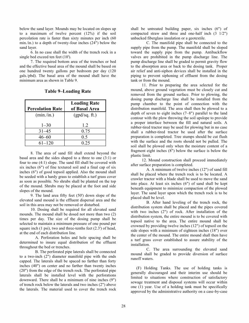
28
below the sand layer. Mounds may be located on slopes up
to a maximum of twelve percent (12%) if the soil
percolation rate is faster than sixty minutes per inch (60
min./in.) to a depth of twenty-four inches (24") below the
sand layer.
6. In no case shall the width of the trench rock in a
single bed exceed ten feet (10').
7. The required bottom area of the trenches or bed
and the effective basal area of the mound shall be based on
one hundred twenty gallons per bedroom per day (120
gals./pbd). The basal area of the mound shall have the
minimum area as shown in Table 9.
Table 9–Loading Rate
Percolation Rate
Loading Rate
of Basal Area
(min./in.)
1–30
(gpd/sq. ft.)
1.2
31–45 0.75
46–60 0.5
61–120 0.25
8. The area of sand fill shall extend beyond the
basal area and the sides shaped to a three to one (3:1) or
four to one (4:1) slope. The sand fill shall be covered with
six inches (6") of fine textured soil and a final cap of six
inches (6") of good topsoil applied. Also the mound shall
be seeded with a hardy grass to establish a turf grass cover
as soon as possible. No shrubs shall be planted on the top
of the mound. Shrubs may be placed at the foot and side
slopes of the mound.
9. The land area fifty feet (50') down slope of the
elevated sand mound is the effluent dispersal area and the
soil in this area may not be removed or disturbed.
10. Dosing shall be required for all elevated sand
mounds. The mound shall be dosed not more than two (2)
times per day. The size of the dosing pump shall be
selected to maintain a minimum pressure of one pound per
square inch (1 psi), two and three-tenths feet (2.3') of head,
at the end of each distribution line.
A. Perforation holes and hole spacing shall be
determined to insure equal distribution of the effluent
throughout the bed or trenches.
B. The perforated pipe laterals shall be connected
to a two-inch (2") diameter manifold pipe with the ends
capped. The laterals shall be spaced no farther than forty
inches (40") on center and no farther than twenty inches
(20") from the edge of the trench rock. The perforated pipe
laterals shall be installed level with the perforations
downward. There shall be a minimum of nine inches (9")
of trench rock below the laterals and two inches (2") above
the laterals. The material used to cover the trench rock
shall be untreated building paper, six inches (6") of
compacted straw and three and one-half inch (3 1/2")
unbacked fiberglass insulation or a geotextile.
C. The manifold pipe shall be connected to the
supply pipe from the pump. The manifold shall be sloped
toward the supply pipe from the pump. Antibackflow
valves are prohibited in the pump discharge line. The
pump discharge line shall be graded to permit gravity flow
to the absorption area or back to the dosing tank. Proper
air relief and anti-siphon devices shall be installed in the
piping to prevent siphoning of effluent from the dosing
tank or from the mound.
11. Prior to preparing the area selected for the
mound, above ground vegetation must be closely cut and
removed from the ground surface. Prior to plowing, the
dosing pump discharge line shall be installed from the
pump chamber to the point of connection with the
distribution manifold. The area shall then be plowed to a
depth of seven to eight inches (7–8") parallel to the land
contour with the plow throwing the soil upslope to provide
a proper interface between the fill and natural soils. A
rubber-tired tractor may be used for plowing but in no case
shall a rubber-tired tractor be used after the surface
preparation is completed. Tree stumps should be cut flush
with the surface and the roots should not be pulled. The
soil shall be plowed only when the moisture content of a
fragment eight inches (8") below the surface is below the
plastic limit.
12. Mound construction shall proceed immediately
after surface preparation is completed.
A. A minimum of twelve inches (12") of sand fill
shall be placed where the trench rock is to be located. A
crawler tractor with a blade shall be used to move the sand
into place. At least six inches (6") of sand shall be kept
beneath equipment to minimize compaction of the plowed
layer. The sand layer upon which the trench rock is to be
placed shall be level.
B. After hand leveling of the trench rock, the
distribution system shall be placed and the pipes covered
with two inches (2") of rock. After installation of the
distribution system, the entire mound is to be covered with
topsoil native to the area. The entire mound shall be
crowned by providing twelve inches (12") of topsoil on the
side slopes with a minimum of eighteen inches (18") over
the center of the mound. The entire mound shall then have
a turf grass cover established to assure stability of the
installation.
C. The area surrounding the elevated sand
mound shall be graded to provide diversion of surface
runoff waters.
(F) Holding Tanks. The use of holding tanks is
generally discouraged and their interim use should be
limited to situations where construction of satisfactory
sewage treatment and disposal systems will occur within
one (1) year. Use of a holding tank must be specifically
approved by the administrative authority on a case-by-case

29
basis which may require stipulations in a signed agreement
regarding the use and the length of time for use of the
holding tank.
1. A holding tank shall be constructed of the
materials and by the same procedures as those specified
for watertight septic tanks.
2. A cleanout pipe of at least six inches (6")
diameter shall extend to the ground surface and be
provided with seals to prevent odor and exclude insects
and vermin. A manhole of at least twenty inches (20")
least dimension shall extend through the cover to a point
within twelve inches (12") but no closer than six inches
(6") below finished grade. The manhole cover shall be
covered with at least six inches (6") of earth.
3. The tank shall be protected against flotation
under high water table conditions. This shall be achieved
by weight of the tank, earth anchors or shallow bury
depths.
4. For a residence, the size shall be one thousand
gallons (1000 gals.) or four hundred gallons (400 gals.)
times the number of bedrooms, whichever is greater. For
permanent structures, other than residences, the capacity
shall be based on measured flow rates or estimated flow
rates. The tank capacity shall be at least five (5) times the
daily flow rate.
5. Holding tanks shall be located as follows:
A. In an area readily accessible to the pump truck
under all weather conditions;
B. As specified for septic tanks in Table 1 set
forth in subsection (1)(D) of this rule; and
C. Where accidental spillage during pumpage
will not create a nuisance.
6. A contract for disposal and treatment of the
sewage wastes shall be maintained by the owner with a
pumper, municipality, agency or firm which possesses a
current and valid permit issued by the Department of
Natural Resources for such activity.
7. Holding tanks shall be monitored to minimize the
chance of accidental sewage overflows. Techniques such
as visual observation, warning lights or bells, or regularly
scheduled pumping shall be used. For commercial
establishments, a positive warning system shall be
installed which allows twenty-five percent (25%) reserve
capacity after actuation.
8. Holding tanks used in conjunction with
permanent black water/gray water systems must conform
to the requirements of this section except that the
minimum size tank is one thousand gallons (1000 gals.). In
these situations, the holding tank is to receive toilet wastes
only.
(G) Sand Filters. Septic tanks or aeration units and sand
filters may be used along with soil absorption systems in
soils with percolation rates between sixty and one hundred
twenty minutes per inch (60–120 min./in.). These systems
must be specifically approved by the administrative
authority.
1. The septic tank and aeration units must be in
accordance with section (4) of this rule. Setback distances
as shown in Table 1 and as specified in subsection (1)(D)
of this rule shall apply except that the minimum distance
to the downslope property line should be fifty feet (50').
2. The following shall apply to gravity flow sand
filter systems:
A. All piping in a sand filter shall be four inch
(4") polyvinyl chloride (PVC). Perforated pipe should be
used for distribution and collection lines;
B. All sand filters shall be dosed at two (2) times
per day. Dosing shall provide uniform distribution of
wastewater throughout the filter cross-section and allow
time for reaeration of the pore spaces to occur. Dosing
may be accomplished by either pumps or siphons;
C. Effluent from filter underdrains must be
collected and disposed of properly. Effluent shall not
discharge off the owner’s property;
D. Buried sand filters shall be in conformance
with Table 10 of this rule. One (1) collector line shall be
provided for every six feet (6') of bed width, with a
minimum of two (2) collector lines per bed. The collector
lines shall have a minimum grade of one percent (1%).
(I) Distribution lines shall be level and spaced
a maximum of three feet (3') apart. Each distribution line
must be vented (downstream end) or connected to a
common vent. Vents should extend at least twelve inches
(12") above the ground surface with the outlet screened or
capped (perforated).
(II) Septic tank effluent shall be applied to the
filter through a distribution box. Buried filters shall be
dosed with a pump or siphon. The dosing volume shall be
sufficient to fill the pore spaces in the gravel to a depth of
four inches (4"). For single bed filters receiving septic tank
effluent, the hydraulic loading rate shall not exceed one
gallon per day per square foot (1 gpd/sq. ft.) with a
maximum organic loading of one and three-fourths pounds
(1 3/4 lbs.) of biological oxygen demand (BOD) per day
per one thousand square feet (1000 sq. ft.) of surface area.
Total surface area shall not be less than two hundred
square feet (200 sq. ft.); and
E. Open sand filters are similar to buried filters
with the exception that no soil backfill or gravel is used on
the top of the sand and the filter must be enclosed within
concrete walls or other substantially equivalent material.
Open sand filters shall be in conformance with Table 10.
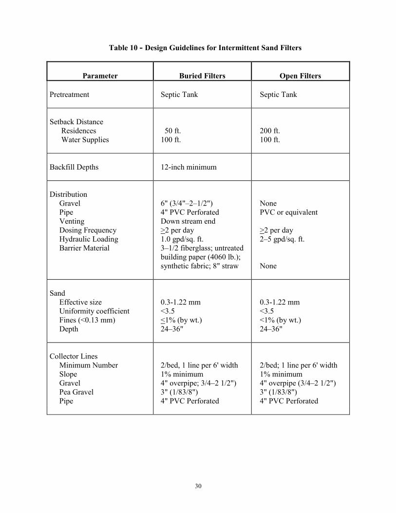
30
Table 10 - Design Guidelines for Intermittent Sand Filters
Parameter
Buried Filters
Open Filters
Pretreatment
Septic Tank
Septic Tank
Setback Distance
Residences
Water Supplies
50 ft.
100 ft.
200 ft.
100 ft.
Backfill Depths
12-inch minimum
Distribution
Gravel
Pipe
Venting
Dosing Frequency
Hydraulic Loading
Barrier Material
6" (3/4"–2–1/2")
4" PVC Perforated
Down stream end
>2 per day
1.0 gpd/sq. ft.
3–1/2 fiberglass; untreated
building paper (4060 lb.);
synthetic fabric; 8" straw
None
PVC or equivalent
>2 per day
2–5 gpd/sq. ft.
None
Sand
Effective size
Uniformity coefficient
Fines (<0.13 mm)
Depth
0.3-1.22 mm
<3.5
<1% (by wt.)
24–36"
0.3-1.22 mm
<3.5
<1% (by wt.)
24–36"
Collector Lines
Minimum Number
Slope
Gravel
Pea Gravel
Pipe
2/bed, 1 line per 6' width
1% minimum
4" overpipe; 3/4–2 1/2")
3" (1/83/8")
4" PVC Perforated
2/bed; 1 line per 6' width
1% minimum
4" overpipe (3/4–2 1/2")
3" (1/83/8")
4" PVC Perforated
31
(I) Distribution of wastewater shall be applied
by pipes directly over the sand surface at the center of the
bed or at the four corners. Splash plates beneath points of
discharge must be used to prevent erosion of the sand.
Curbs around the splash plates or large stones placed
around the periphery of the plate will help prevent
scouring. All exposed pipes shall slope to drain.
(II) Filter walls shall be concrete, masonry,
compacted clay, high density polyethylene plastic with a
minimum thickness of thirty (30) mil, or other material
acceptable to the administrative authority; and extend six
inches (6") above the sand and six inches (6") above the
adjacent ground level.
(III) Dosing shall flood the bed to a depth of
two inches (2") with a hydraulic loading of two to five
gallons per day per square foot (2–5 gpd/sq. ft.) (septic tank
effluent). Maximum organic loading is five and thirteen-
hundredths pounds (5.13 lbs.) of BOD per day per one
thousand square feet (1000 sq. ft.) of surface area.
(IV) The filter may be covered to provide
protection against severe weather, prevent growth of weeds
and to keep children and animals out of the filter. Such
cover may include six inches (6") of clean one to two inch
(1-2") gravel, if so designed by an engineer as part of the
system. In such event, a vent for the system would not be
required if so determined by the engineer.
3. The following shall apply to pressure dosed sand
filter systems:
A. Conventional pressure dosed sand filters use
an intermittent filter with two feet (2') or more of medium
sand designed to filter and biologically treat sewage tank
effluent from a pressure distribution system at an
application rate not to exceed one and twenty-five
hundreths gallons per square foot (1.25 gals./sq. ft.) sand
surface area per day, applied at a dose not to exceed one-
half gallon (1/2 gal.) per orifice per dose. These sand
filters may be buried or open.
B. Recirculating pressure dosed sand filters use a
recirculating filter with two feet (2') or more of medium
filter media designed to filter and biologically treat sewage
tank effluent from a pressure distribution system at an
application rate not to exceed five gallons per square foot
(5 gals./sq. ft.) filter surface per day, applied at a dose not
to exceed two gallons (2 gals.) per orifice per dose. These
sand filters shall be uncovered and open to the surface.
C. Minimum filter area for these filters shall be
as follows:
(I) Conventional pressure dosed sand filters for
single family residences shall be a minimum of three
hundred and sixty square feet (360 sq. ft.) in surface area
with a design sewage flow not to exceed six hundred
gallons (600 gals.). If sand filter design flows exceed an
average of four hundred and fifty gallons per day (450
gpd), the minimum sand surface will be based on one and
twenty-five hundredths gallons per day per square foot
(1.25 gpd/sq. ft.); and
(II) Pressure dosed sand filters for commercial
facilities shall be sized on the basis of projected daily
sewage flow. If the waste strength is proposed to be greater
than residential strength waste, pretreatment shall be
required which will reduce the biological oxygen demand
to levels not to exceed three hundred (300), total suspended
solids to levels not to exceed one hundred-fifty (150), and
oil and grease to levels not to exceed twenty-five (25). The
minimum sand surface will be based on two to five gallons
per day per square foot (2-5 gpd/sq. ft.).
D. Design criteria shall include the following:
(I) Sewage tanks shall be in accordance with
section (4) of this rule. Set-back distances as shown in
Table 1 of subsection (1)(D) and as specified in subsection
(1)(E) of this rule shall apply, unless a variance has been
allowed by the administrative authority. Tanks shall be
watertight and tested in the field. The test shall be
performed by filling the tank two inches (2") above the
riser inlet. At the end of the first twenty-four (24)-hour
period, the tank water level should be refilled. After
another twenty-four (24)-hour period, no more than one
inch (1") of water should have dropped from the original
reading. All sewage and pump tanks will be supplied with
vandal-proof access risers to grade over the pump units.
Risers should have a waterproof epoxy seal between the
tank and riser;
(II) Pumping systems for a pressure dosed
sand filter system should provide pumping apparatus that is
capable of filtering gross solids larger than one-eighth inch
(1/8") and draw from the clear zone near the outlet side of
the sewage tank. This zone is described as the layer of
effluent between the sludge and scum layers of the sewage
tank. Pumps should be able to deliver adequate head
pressure to control orifice plugging. Pumps should be
made of a corrosive resistant material such as Type 316
stainless steel, suitable plastic, or 85-5-5-5 bronze. Screens
should have at least ten square feet (10 sq. ft.) of surface
area, with one-eighth inch (1/8") openings;
(III) Operation controls should be on a timer
dose that distributes the average daily flow over an
eighteen (18)-hour period. Recirculating filters will be set
to recirculate five (5) times the average daily flow over a
twenty-four (24)-hour period. Systems should be designed
with a high water alarm and light signal. Control panels
should be located on an exterior location. Control
operations should be located in an area available for
maintenance;
(IV) Intermittent filter media shall be a
mixture of sand or durable inert particles with one hundred
percent (100%) passing the three-eighths inch (3/8") sieve;
ninety to one hundred percent (90-100%) passing the No. 4
sieve; sixty-two to one hundred percent (62-100%) passing
the No. 10 sieve; forty-five to eighty-two percent (45-82%)
passing the No. 16 sieve; twenty-five to fifty-five percent
(25-55%) passing the No. 30 sieve; ten percent (10%) or
less passing the No. 60 sieve; four percent (4%) or less
passing the No. 100 sieve; or sand meeting the ASTM-C 33
32
concrete sand specification minus four percent (4%) or less
passing the No. 100 sieve. All drainage rock should be a
river washed, hardened and weathered rock. The treatment
media will be two inches (2") deep and of a coarse media
with an effective size of one and one-half to three
millimeters (1 1/2-3 mm) and a uniformity coefficient of
less than two (2). Limestone or dolomite is not acceptable
for drainage rock;
(V) Recirculating filter media shall be a
mixture of sand or durable inert particles with one hundred
percent (100%) passing the three-eighths inch (3/8") sieve;
seventy-nine to one hundred percent (79-100%) passing the
No. 4 sieve; eight to ninety-two percent (8-92%) passing
the No. 8 sieve; zero to fifteen percent (0-15%) passing the
No. 30 sieve; zero to one percent (0-1%) passing the No. 50
sieve. All drainage rock should be a river washed,
hardened and weathered rock. The treatment media will be
two inches (2") deep and of a coarse media with an
effective size of one and one-half to three millimeters (1
1/2-3 mm) and a uniformity coefficient of less than two (2).
Limestone or dolomite is not acceptable for drainage rock;
and
(VI) Container designs may be concrete
containers consisting of watertight walls and floors to
prevent groundwater from infiltrating or effluent from
exfiltrating from the filter. All penetrations through the
walls shall be water-tight. Containers may also consist of a
thirty (30) mil polyvinyl chloride liner covering the sand
filter bottom and side wall areas. Polyvinyl chloride liners
should be supplied with repair kits and boots for passage
through the liner wall. The bottom area of the liner should
be bedded in two inches (2") of leveling sand. The liner
should be constructed to form a waterproof membrance
between the trench bottom and trench walls. The polyvinyl
liner should incorporate all seams to be a chemically or
heat bonded waterproof seam.
E. The filter design criteria shall include the
following:
(I) The interior base of the filter container
shall be level or constructed at a grade of one percent (1%)
or less to the underdrain pipe elevation;
(II) The underdrain piping shall consist of a
pipe with one-fourth inch (1/4") grooves cut every four
inches (4") along the pipe length to a depth of one-half
(1/2) of the pipe diameter. The bottom of the filter
container shall be covered with a minimum of six inches
(6") of drain media. The underdrain pipe shall be
enveloped in an amount and depth of drainage rock to
prevent migration of the underdrain media into the pipe
perforations;
(III) A minimum of twenty-four inches (24")
of approved filter media shall be installed over the
underdrain media. The media shall be damp at the time of
installation to insure compaction of the media. The top
surface of the media shall be level;
(IV) There shall be a minimum of three inches
(3") of clean drain media below the distribution laterals,
and sufficient media above the laterals equal to or covering
the orifice shields and/or pipe;
(V) Distribution laterals shall be evenly
spaced on minimum, thirty inch (30") centers. Orifices
shall be placed such that there is one (1) orifice or more on
average per six square feet (6 sq. ft.) of sand surface.
Orifice holes shall be one-eighth inch (1/8") in diameter.
The diameter of the piping manifold and lateral shall be no
less than one-half inch (1/2"). The ends of the distribution
laterals should be constructed with a means to perform
flushing of the piping, collectively or individually, through
the operation of a flushing valve. The flushed effluent may
be discharged to the sand filter;
(VI) The top of the intermittent media in
which the pressure distribution system is installed shall be
covered with a breathable nylon or polypropylene spun
filter fabric rated at eighty-five hundredths ounce per
square yard (0.85 oz./sq. yd.) to eliminate soil intrusion into
the filter media. Recirculating filters shall be open-topped;
(VII) The top of the intermittent sand filter
area shall be backfilled with a soil cover, free of rocks,
vegetation, wood waste, etc. The soil cover shall have a
textural class of loamy sand. The soil cover shall have a
minimum depth of six inches (6") and a maximum depth of
twelve inches (12"). Intermittent sand filters designs may
delete soil cover and incorporate three to six inches (3-6")
of a quality cypress or cedar mulch over the entire filter
area;
(VIII) Where the effluent from a sand filter is
to be discharged via a pump, the pump and related
apparatus shall be housed in a vandal resistant vault
designed to withstand the stresses placed upon it and not
allow the migration of drain media, sand or underdrain
media to its interior. The vault shall have a durable, affixed
floor. The vault shall provide watertight access to the
finished grade with a diameter equal to that of a gravity
discharge sand filter. The depth of the underdrain and the
operational level of the pump cycle and alarm shall not
allow effluent to come within two inches (2") of the bottom
of the sand filter media. The pump off level shall be no
lower than the invert of the perforations of the underdrain
piping. The internal sand filter pump shall be electrically
linked to the sand filter dosing apparatus in such a manner
as to prevent effluent from entering the sand filter in event
the internal sand filter pump fails; and
(IX) Other sand filters which vary in design
from those described in this rule may be authorized by the
administrative authority if they can be demonstrated to
produce a comparable effluent quality.
F. Effluent from these sand filters may discharge
to the ground surface, provided the effluent is maintained
on the owner’s property and the following separation
distances are maintained:
(I) The discharge shall be a minimum of one
hundred feet (100') from private water supply wells; one
hundred-fifty feet (150') from unplugged abandoned wells
33
or wells with less than eighty feet (80') of casing; and three
hundred feet (300') from public water supply wells;
(II) The discharge shall be a minimum of one
hundred feet (100') from springs; five hundred feet (500')
from the edge of surficial sink holes; fifty feet (50') from a
classified stream; and twenty-five feet (25') from a stream
or open ditch; and
(III) The discharge shall be a minimum of
seventy-five feet (75') from property lines.
G. If effluent can not meet the minimum
separation distances as described in subparagraph
(6)(G)2.F., then the effluent must be disposed of into a soil
absorption system. The required footage of the soil
absorption system may be reduced by up to one-third (1/3)
of that required for a conventional soil absorption system.
Shallow bury designs should be utilized whenever possible
to achieve the best absorption rates.
(H) Drip Soil Absorption. Drip soil absorption also
known as trickle irrigation may be approved by the
administrative authority in accordance with section (6) of
this rule. Due to the various pretreatment methods and
appurtenances and lack of extensive experience, drip soil
absorption systems must be viewed as experimental, and
back-up design for another system shall be approved in
case of failure of the drip soil absorption system.
1. Drip lines shall be placed two feet (2') apart in a
parallel arrangement. Emitters shall be placed in the drip
lines every two feet (2') so there will be a two-foot by two-
foot (2’x2') grid pattern. Other configurations and spacings
of the drip line and emitters may be used; however, each
emitter will be considered to cover four square feet (4 sq.
ft.)of absorption area.
2. The application rate shall not exceed the values as
shown in Table 7 for low pressure pipe systems in
subparagraph (6)(C)3.A of this rule.
3. Drip soil absorption systems may be allowed at
sites where the soil is classified as being in group IVb. A
minimum separation distance of twelve inches (12") shall
be maintained between the drip lines and emitters and a
high ground water table or other limiting condition. The
maximum application rate for IVb soils shall be from five-
hundredths to one-tenth gallons per day per square foot
(0.05–0.10 gpd/sq. ft.) of absorption field.
(I) Wetlands. Constructed wetlands provide secondary
levels of treatment, which means that some form of
pretreatment (septic tank, aeration tank, lagoon, etc.) must
be used prior to the wetland, as wetlands cannot withstand
large influxes of suspended solids. The pretreatment used
must be capable of removing a large portion of these solids.
Effluent from wetlands must be contained on the owner’s
property with the same set-back distances as required for
lagoons in Table 1, located in subsection (1)(D) of this rule.
1. Free water surface wetlands are shallow beds or
channels with a depth less than twenty-four inches (24”)
and filled with emergent aquatic plants. This type of
wetland shall not be allowed.
2. Submerged flow wetlands are similar to free water
surface wetlands except that the channels are filled with
shallow depths of rock, gravel or sand. The depth of the
porous media is usually less than eighteen inches (18”).
The porous media supports the root systems of the
emergent aquatic vegetation. The water level is to be
maintained below the top of the porous media so that there
is no open water surface.
3. The surface area of wetlands shall be determined
by using the following equation:
As = [Q(in Co – In Ce)]/(kT x f x d) where: As = wetland surface area, sq. ft.
Q = daily flow rate to wetland, cu. ft./day
([gallons/day] ÷ 7.5);
Co = influent BOD5 concentration, mg/L;
Ce = effluent BOD5 concentration, mg/L;
kT = temperature dependent rate constant,
per day;
d = water depth in wetland, ft; and
f = void fraction of rock media, decimal.
4. After a surface area has been determined, a cross-
sectional area shall be calculated against hydraulic loading
by using the following equation:
Ah = Q/(Kh x S) where: Ah = cross-sectional area (hydraulic loading),
sq. ft.;
Kh = hydraulic conductivity of rock media,
ft./day*; and
S = slope of wetland bottom, decimal.**
* A value of eight hundred feet per day (800
ft./day) may be used for the hydraulic
conductivity for rock of one inch (1”) diameter.
** Values for slope should range between twenty-
five hundredths and one percent (0.25–1%).
5. After the hydraulic loading has been determined,
an organic loading shall be calculated using the following
equation:
Ao = OGL/0.05 where: Ao = cross-sectional area (organic loading),
sq. ft.; and
OGL = organic loading, lbs BOD5/day.
6. The larger of the two (2) calculations, the
hydraulic loading or the organic loading, shall be used to
determine the wetland dimensions. Wetlands should not be
long and narrow.
7. The width of the wetland shall be calculated by
dividing the larger cross-sectional area by the water depth.
The calculated width should not be less than one-third (1/3)
of the length (a length:width ratio of three to one (3:1)).

34
Should it be necessary to construct a wetland with a ratio
greater than three to one (3:1), step-loading along the
length of the wetland shall be considered.
8. The configuration of a wetland for an individual
home can be a one (1) cell or two (2) cells in series,
depending upon the soil properties at the site. Larger
systems may consist of multiple cells in parallel or series in
order to provide more management options.
A. Single cells may be used where there will be
no percolation of water through the bottom of the wetland.
Water movement properties of the soil at the wetland
construction site must be determined either by use of
properly performed percolation tests or a thorough soil
profile analysis performed by a qualified person meeting
the criteria of 19 CSR 20.3.080.
B. For soils with percolation rates of sixty
minutes per inch (60 min./in.) or less and where geological
limitations are not severe, a two (2)-cell wetland may be
used. The first cell shall be lined, allowing no percolation.
The second cell may be unlined and filled with sand (not
rock) to promote some percolation from the bottom of the
wetland. The second cell shall not be larger than the first
cell.
9. Crushed limestone or other rock with sharp edges
shall not be used for a porous media as this type of rock
will compact with time. Rock with rounded edges, such as
creek gravel, shall be used. Rock must be thoroughly
washed to remove fines which may cause plugging. Rock
substrate size should be one inch (1”) diameter, while rock
to be used around inlet and outlet pipes may be two to four
inches (2-4”) diameter to reduce potential clogging. A three
to four inch (3-4”) layer of washed pea gravel may be used
on top of the one inch (1”) substrate for decorative
purposes.
10. All piping shall be SDR 35 sewer pipe, Schedule
40 polyvinyl chloride (PVC) DWV pipe, or material of
equivalent or stronger construction. Piping shall be a four
inch (4”) diameter.
11. Influent shall be distributed and effluent
collected by header pipes running the width of the wetland.
Perforated sewer pipe can be used for the headers. For
unperforated pipe, a one and one-half inch (1 1/2”) hole
shall be drilled every twelve inches (12”) along the header.
Headers shall be placed at the bottom of the wetland on a
bed of rock and covered with two to four inch (2-4”) rock.
A cleanout shall be placed before the influent header.
A. If effluent from the septic tank flows to the
wetland by gravity and there are parallel cells in the
wetland, a distribution box shall be placed ahead of the
wetland so that flow can be controlled to individual cells.
B. If effluent is pumped, the pumping rate shall
not exceed twenty-five gallons per minute (25 gpm) and no
more than one-third (1/3) of the daily design flow shall be
pumped at one (1) time.
12. Water level in a wetland shall be controllable.
The range of control shall be from two inches (2”) above
the surface of the rock to complete draining of the wetland.
Maximum water level in the wetland shall be a minimum of
twelve inches (12”) below the outlet of the septic tank so
that water does not back up into the septic tank.
A. To conveniently check the water level relative
to the gravel surface, a four inch (4”) diameter perforated
pipe may be placed in the bottom of the wetland, through
the channel embankment, and then elbowed up to the
elevation of the top of the channel.
B. Water level control may be obtained by use of
swivel standpipes or collapsible tubing.
13. Surface water shall be kept out of the wetland.
This may be accomplished by diverting runoff away from
the wetland or constructing an earthen berm around the
wetland. Berms shall be a minimum of six inches (6”)
above the surface of the porous media.
14. Emergent plants shall be selected by the ability
of the plants to: root and grow in the wastewater-rock
environment, treat wastewater to acceptable levels, produce
biomass in amounts that can be controlled and aesthetics.
Reference may be made to Tables 11 and 12 in selecting
desired plants.

35
Table 11 - Plant Growth Data after one growing season
Softstem Bulrush
(Scirpus validus)
(lbs./sq. ft.)
9.74
(lbs./sq. ft.)
4.20
3.20
1.00
3.20
(inches)
7.0
Horsetail
(Equisetum hyemale)
1.90
0.55
0.20
0.35
0.57
11.0
Water Iris
(Iris pseudacorus)
3.28
0.66
0.31
0.35
0.90
8.0
Pickerel Rush
(Pontederia cordata)
6.24
1.30
0.50
0.80
0.63
15.0
Arrowhead
(Sagittaria latifolia)
2.25
0.35
0.17
0.18
0.94
10.0
Cattails
(Typha latifolia)
7.89
3.00
1.90
1.10
1.73
8.0
Soft Rush
(Juncus effusus)
3.00
1.05
0.65
0.40
1.62
18.0
Flowering Rush
(Butomus umbellatus)
0.30
0.07
0.01
0.06
0.18
12.0
Table 12 - Characteristics of Emergent Aquatic Plants
Plant Species
Bloom
Date
Type of
Bloom
Bloom
Color
Plant
Height
Growth
Pattern
Initial
Spacing
Softstem Bulrush
(Scirpus validus)
June–July
Oblong
Spikelets
Gray
(inches)
40–60
Spreading
(feet)
3
Horsetail
(Equisetum
hyemale)
July–Aug.
Oblong
Spikelets
Brown
30–40
Spreading
3
Water Iris
(Iris pseudacorus)
May–Aug.
Flower
White-
Lt. Blue
10–18
Bunches
2–3
Pickerel Rush
(Pontederia
cordata)
July–Sept.
Flower
Purple
10–18
Bunches
2
Arrowhead
(Sagittaria latifolia)
June–July
Hanging
Bulbs
Green-
White
6–10
Spreading
2–3
Cattails
(Typha latifolia)
May–June
Oblong
Spike
Brown
48–72
Spreading
3
Soft Rush
(Juncus effusus)
June–July
Flower
Brown
18–30
Bunches
2
Plant Species
Wet
Weight
Dry
Weight
Top Dry
Root Dry
Top/Root
Root
Depth
36
(J) Privy. A privy will be allowed only under limited
conditions and will not be recognized as a method of
sewage disposal for a continuously occupied dwelling,
business or other structure. A privy will only be considered
for remote areas not served by a piped water source.
Examples of these areas may be a rural cemetery, a rural
church with a small congregation and where hand-washing
facilities are available, or a river access point provided by
the Department of Conservation. Plans and construction of
a privy will need to meet the approval of the administrative
authority.
1. The privy shall be used to receive only human
excreta and toilet paper. The privy shall not be used as a
depository for other wastes.
2. A pit shall be provided for the privy. The sides of
the pit shall be curbed to prevent cave-in. If the pit has an
earth bottom, the bottom shall be at least three feet (3’)
above saturated soil conditions. If this separation distance
cannot be achieved in the location of the privy, then the pit
shall be liquid tight.
3. The pit shall be periodically pumped out by
someone who services septic tank systems. At no time shall
the pit contents be allowed to accumulate to within one foot
(1’) of the pit top. The pit contents shall then be transported
and disposed into a community sewer system that is in
compliance with Chapter 644, RSMo.
4. Both the pit and the privy shall be vented. Insect-
proof openings shall be placed in the walls, below the seat.
A vent shall extend from the underside of the seat board
through the roof or up to a horizontal vent open to the sides
of the toilet. This vent must be flush with the underside of
the seat board and shall not extend down into the pit. All
vent openings to the outside shall be properly screened to
keep out insects. The top of the privy shall have a screened
opening on each side. It is preferable the opening be all the
way around the top of the privy in order to allow air to pass
through and to carry away any odors which may seep into
the upper part of the structure. If a crescent-shaped opening
is cut into the door or wall of the privy, it shall also be
screened.
5. The inside of the privy shall be of durable,
smooth, non-absorbent material. If wood is used, the inside
of the structure shall be coated with a polyurethane-type
coating so as to minimize the penetration of liquids and
odors into the wood.
6. A tight-fitting door, preferably with a self-closing
feature, such as a door spring, shall be used.
7. A privy shall be set back from surface waters,
buildings, property lines and water supply wells the same
distance as required for soil treatment areas. This
information may be found in subsection (1)(D), Table 1 of
this rule.
8. The privy shall be of sufficient capacity for the
facility it serves, but shall have at least fifty cubic feet (50
cu. ft.) of capacity.
9. Abandoned pits shall have the contents removed,
transported and disposed into a community sewer system
that is in compliance with Chapter 644, RSMo. This
activity shall be performed by someone who services septic
tank systems. The pit shall then be filled with clean earth
and slightly mounded to allow for settling.
(K) Other Systems. Where unusual conditions exist,
special systems of treatment and disposal, other than those
specifically mentioned in this rule, may be employed
provided–
1. Reasonable assurance of performance of the
system is presented to the administrative authority;
2. The engineering design of the system is first
approved by the administrative authority;
3. Adequate substantiating data indicate that the
effluent will not contaminate any drinking water supply,
groundwater used for drinking water or any surface water;
4. Treatment and disposal of the wastes will not
deteriorate the public health and general welfare;
5. Discharge of effluent, if any, shall be within set-
back distances as described in Table 1, located in
subsection (1)(D) of this rule; and
6. These systems comply with all applicable
requirements of this rule, with all local codes and
ordinances, and all applicable requirements of sections
701.025-701.055 and Chapter 644, RSMo.
(L) Variances. Variances may be considered and
granted by the administrative authority concerning repair to
on-site sewage disposal systems existing prior to January 1,
1996 with site limitations or for property platted prior to
January 1, 1996 with site limitations. Where variances have
been allowed from the standards, the administrative
authority may require that a higher level of pretreatment
than that of a septic tank be provided. At the discretion of
the administrative authority and with relative assurance for
protection of the public health and preservation of the
quality of surface and ground waters, variances may be
allowed for the following:
1. Setbacks as specified in Table 1, located in
subsection (1)(D) of this rule;
2. Minimum distance between the infiltrative surface
and restrictive feature or bedrock;
3. Minimum areas for infiltrative surfaces as shown
in Table 5 (see (5)(A)4.), Table 6 (see (5)(A)16.C.), Table
7 (see (6)(C)3.A.), Table 8 (see (6)(E)3.), Table 9 (see
(6)(E)7.) and Tables 13 and 14 (see (7)(M)) of this rule;
4. A written application for a variance shall be
provided to the administrative authority and shall provide
the following:
A. An explicit description explaining why the
requirements of this rule cannot be complied with,
including a description of specific sections of this rule for
which a variance is being requested;
B. A design of the proposed system. The design
shall show that as much soil absorption as is practically
possible will be installed;
C. The existing and maximum occupancy pattern
and the existing water usage records, if any;
37
D. Potential impact, if any, on neighboring
property owners and the names and mailing addresses of
these property owners; and
E. Adequate substantiating data to indicate that
the effluent will not contaminate any drinking water
supply, groundwater used for drinking water or any surface
water;
5. These systems shall comply with all applicable
requirements of these standards except where variances
have been granted;
6. No variance will be granted for any system that
would result in noncompliance with Chapter 644, RSMo,
Missouri Clean Water law and subsequent rules. On-site
sewage disposal systems with a discharge, other than a
system serving a single family residence lot, must be
referred to the Department of Natural Resources and
comply with Chapter 644, RSMo, Missouri Clean Water
law and subsequent rules;
7. If effluent can not meet the minimum separation
distances as described in Table 1 of subsection (1)(D), then
the effluent must be disposed of into a soil absorption
system. Set-back distances for lagoons will be considered
applicable to alternative systems. The required footage of
the soil absorption system following alternative systems
may be reduced by up to one-third (1/3) of that required for
a conventional soil absorption system. Shallow bury
designs should be utilized whenever possible to achieve the
best absorption rates;
8. All adjacent and/or affected property owners shall
be notified in writing by the administrative authority
whenever consideration for granting a variance is likely to
result in effluent crossing property lines. The party
requesting the variance shall be responsible for supplying
the names and addresses of all adjacent and/or affected
property owners to the administrative authority. Adjacent
and/or affected property owners shall be allowed thirty (30)
days from the date of the written notification to contact the
administrative authority to express comments concerning
the consideration of granting a variance; and
9. In cases of complaint abatement, where effluent
cannot be maintained on the owner’s property, within the
required set-back distances and presents a nuisance or
threat to public health or surface or ground water quality,
the administrative authority may require a holding tank be
placed at the optimum location within the sewage system,
in order to abate the complaint. The owner shall be
responsible for assuring the holding tank is pumped as
needed, with the contents being disposed of in a
Department of Natural Resources permitted facility.
(7) Detailed Soils Evaluation. (A) General. The intent of this section is to provide
minimum standards for site evaluations based upon
evaluation of the soil characteristics, namely texture, color,
structure, drainage and depth. Criteria are also given for
sizing standard systems and some alternative systems.
(B) Adoption and Use. Where this rule is administered
by an administrative authority, those administrative
authorities may adopt this section, in whole or in part, as
part of a local code or ordinance. Nothing in this rule or
section shall require any administrative authority to allow
an installation based upon the criteria contained in this
section. The administrative authority may require
percolation tests in addition to evaluation of soil
characteristics. Whenever percolation tests and these
criteria are used, the size of the proposed system or
suitability of a site should be based upon which criteria
produce the most conservative system. This type evaluation
should be conducted by a professional soil scientist,
engineer, sanitarian or registered geologist with special
training in determining soil morphological characteristics in
the field.
(C) Site Evaluation. An investigation of a proposed soil
absorption site shall consider the following factors:
1. Topography and landscape position;
2. Soil characteristics (morphology) which includes
texture, structure, porosity, consistence, color and other
physical, mineral and biological properties of various
horizons, and the thickness and arrangement of the
horizons in the soil profile;
3. Soil drainage, which includes both external
(surface) and internal (soil);
4. Soil depth;
5. Restrictive horizons; and
6. Available space.
(D) Site evaluations shall be made in accordance with
subsections (7)(E)–(M) of this rule. Based on this
evaluation, each of the factors listed in subsection (7)(C) of
this rule shall be classified as Suitable, Provisionally
Suitable or Unsuitable.
(E) Topography and Landscape Position. Uniform
slopes under fifteen percent (15%) shall be considered
suitable with respect to topography. When slopes are less
than two percent (2%), provisions shall be made to insure
adequate surface drainage. When slopes are greater than
four percent (4%), the absorption lines shall follow the
contour of the ground.
1. Uniform slopes between fifteen percent (15%) and
thirty percent (30%) shall be considered provisionally
suitable with respect to topography, if the soils are thirty-
six inches (36") or more thick. Slopes within this range
may require installation of interceptor drains upslope from
the soil absorption system to remove all excess water that
might be moving laterally through the soil during wet
period. Usable areas larger than minimum are ordinarily
required in this slope range.
2. Slopes greater than thirty percent (30%) shall be
considered unsuitable except when a thorough study of the
soil characteristics indicates that a soil absorption system
will function satisfactorily and sufficient ground area is
available to properly install such a system. Slopes greater
38
than thirty percent (30%) may be classified as provisionally
suitable when all of the following conditions are met:
A. The slope can be terraced or otherwise graded
or the absorption lines located in naturally occurring soil to
maintain a minimum ten-foot (10') horizontal distance from
the absorption trench and the top edge of the fill
embankment;
B. The soil characteristics can be classified as
suitable or provisionally suitable to a depth of at least one
foot (1') below the bottom of the absorption trench;
C. Surface water runoff is diverted around the
absorption field so that there will be no scouring or erosion
of the soil over the field;
D. If necessary, groundwater flow is intercepted
and diverted to prevent the water from running into or
saturating the soil absorption system; and
E. There is sufficient ground area available to
install the septic tank system with these modifications.
3. Complex slope patterns and slopes dissected by
gullies and ravines shall be considered unsuitable to
topography.
4. Areas subject to frequent flooding shall be
considered unsuitable to landscape positions.
5. Depressions shall be considered unsuitable with
respect to landscape positions except when the site
complies essentially with the requirements of this section
and is specifically approved by the administrative authority.
6. If directed by the administrative authority, the
surface area on or around a ground absorption system
sewage treatment and disposal system shall be landscaped
to provide adequate drainage. The interception of perched
or lateral groundwater movement shall be provided where
necessary to prevent soil saturation on or around the ground
absorption sewage treatment and disposal system.
(F) Soil Characteristics (Morphology). Soil borings or
pits shall be taken at the site to be used for soil absorption
systems. These borings shall be taken to a depth of forty-
eight inches (48") or as required to determine the soil
characteristics. Soil borings or pits and core samples shall
be evaluated and a determination made on the suitability of
the soil to treat and absorb septic tank effluent. The
important soil characteristics which shall be reviewed by
the administrative authority are as follows:
1. The relative amounts of the different sizes of
mineral particles in a soil are referred to as soil texture. All
mineral soils are composed of sand, two to five hundredths
milimeters (2–.05 mm) in size; silt, which includes
intermediate-sized particles that cannot be seen with the
naked eye but feel like flour when pressed between the
fingers, five hundredths to two thousandths millimeter
(0.05-0.002 mm) in size; or clay, which is extremely small
in size and is the mineral particle that gives cohesion to a
soil, less than two thousandths millimeters (0.002 mm) in
size or a combination of these. The texture of the different
horizons of soils may be classified into five (5) general
groups and shall be used for determining the application
rates shown in Tables 6 and 7 of this rule.
A. Soil Group I. Sandy texture soils contain more
than seventy percent (70%) sand-sized particles in the soil
mass. These soils do not have enough clay to be cohesive.
Sandy soils have favorable sewage application rates, but
may have a low filtering capacity leading to malfunction
due to contamination of groundwater. The sandy group
includes the sand and loamy sand soil textural classes and
shall generally be considered suitable in texture.
(I) Sand. Sand has a gritty feel, does not stain
the fingers and does not form a ribbon or ball when wet or
moist.
(II) Loamy sand. Loamy sand has a gritty feel,
stains the fingers (silt and clay), forms a weak ball and
cannot be handled without breaking.
B. Soil group II. Coarse loamy texture soils
contain more than thirty percent (30%) sand-sized particles
and fewer than twenty percent (20%) clay-sized particles in
the soil mass. They exhibit slight or no stickiness. The
coarse loamy group includes sandy loam and loam soil
textural classes and shall generally be considered suitable
in texture.
(I) Sandy loam. Sandy loam feels gritty and
forms a ball that can be picked up with the fingers and
handled with care without breaking.
(II) Loam. Loam may feel slightly gritty but
does not show a fingerprint and forms only short ribbons
ranging from twenty-five hundredths to fifty hundredths
inch (.25-.50") in length. Loam will form a ball that can be
handled without breaking.
C. Soil group III. These fine loamy texture soils
contain fewer than forty percent (40%) clay-sized particles
and not more than thirty percent (30%) sand-sized particles
in a soil mass. Also this group is limited to less than thirty-
five percent (35%) clay when the clay minerals exhibit high
shrink/swell characteristic and exhibit slight to moderate
stickiness. The fine loamy group includes sandy clay loam,
silt loam, clay loam and silty clay loam textural classes and
shall generally be considered provisionally suitable in
texture.
(I) Silt loam. Silt loam feels floury when moist
and will show a fingerprint but will not ribbon and forms
only a weak ball.
(II) Silt. Silt has a floury feel when moist and
sticky when wet but will not ribbon and forms a ball that
will tolerate some handling.
(III) Sandy clay loam. Sandy clay loam feels
gritty but contains enough clay to form a firm ball and may
ribbon to form seventy-five hundredths to one-inch (.75-1")
pieces.
(IV) Silty clay loam. Silty clay loam is sticky
when moist and will ribbon from one to two inches (1-2").
Rubbing silty clay loam with the thumbnail produces a
moderate sheen. Silty clay loam produces a distinct
fingerprint.
(V) Clay loam. Clay loam is sticky when
moist. Clay loam forms a thin ribbon of one to two inches
(1-2") in length and produces a slight sheen when rubbed
39
with the thumbnail. Clay loam produces a non-distinct
fingerprint.
D. Soil group IV. These clayey texture soils
contain forty percent (40%) or more clay-sized particles
and include sandy clay, silty clay and clay. This group may
also include clay loam and silty clay loam when the clay
fraction is greater than thirty-five percent (35%) and of a
high shrink/swell nature. There are two (2) major types of
clays–non-expandable and expandable. The non-
expandable clays, when wet, are slightly sticky to sticky;
when moist, are friable to firm; and when dry, they are
slightly hard to hard. The non-expandable clays (Group
IVa) shall generally be considered provisionally suitable in
texture. The expandable clays, when wet, are very sticky
and very plastic and when moist, these clays are very firm
to extremely firm and when dry, are very hard to extremely
hard. The expandable clays (Group IVb) shall be
considered unsuitable in texture.
(I) Sandy clay. Sandy clay is plastic, gritty and
sticky when moist and forms a firm ball and produces a
thin ribbon to over two inches (2") in length.
(II) Silty clay. Silty clay is both plastic and
sticky when moist and lacks any gritty feeling. Silty clay
forms a firm ball and readily ribbons to over two inches
(2") in length.
(III) Clay. Clay is both sticky and plastic when
moist, produces a thin ribbon over two inches (2") in
length, produces a high sheen when rubbed with the
thumbnail and forms a strong ball resistant to breaking.
E. Soil group V. This soil group may be of any
texture, however, the most predominant are cherty and very
cherty clays, silt loams and silty clay loams. The amount of
rock fragments in these soils is of a concern in areas of
residual soils overlying highly permeable bedrock where
groundwater could become contaminated. In general, soils
with less than fifty percent (50%) rock fragments will be
considered suitable. In general, soils with greater than fifty
percent (50%) rock fragments over highly permeable
bedrock will be considered unsuitable. Soils with greater
than fifty percent (50%) rock fragments will be considered
provisionally suitable if geological limitations are not
severe.
F. The soil texture shall be estimated by field
testing; and
2. Soil consistency. Soil consistency is comprised of
the attributes of soil material, typically clay, that are
expressed by the degree and kind of cohesion and adhesion
or by the resistance to deformation or rupture.
A. Soil consistency when wet shall be considered
as follows:
(I) Stickiness. Stickiness is the quality of
adhesion to other objects. For field evaluation of stickiness,
wet soil material is pressed between thumb and finger and
its adherence noted. Degrees of stickiness are described as
follows:
(a) Slightly sticky. After pressure, soil
material adheres to both thumb and finger but comes off
one or the other cleanly. It is not appreciably stretched
when the digits are separated;
(b) Sticky. After pressure, soil material
adheres to both thumb and finger and tends to stretch
somewhat and pull apart rather than pulling free from either
digit; and
(c) Very sticky. After pressure, soil material
adheres to both thumb and finger and is decidedly stretched
when they are separated; and
(II) Plasticity. Plasticity is the ability to change
shape continuously under the influence of an applied stress
and to retain the impressed shape on removal of the stress.
For field determination of plasticity, the soil material shall
be rolled between the thumb and finger to observe whether
or not a wire or thin rod of soil can be formed. Degree of
resistance to deformation at or slightly above field capacity
is as follows:
(a) Slightly plastic. Wire formable but soil
mass easily deformable;
(b) Plastic. Wire formable and moderate
pressure required for deformation of the soil mass; and
(c) Very plastic. Wire formable and much
pressure required for deformation of the soil mass.
B. Soil consistency when moist. Consistence
when moist is determined at a moisture content
approximately midway between air dry and field capacity.
At this moisture content, most soil materials exhibit a form
of consistency characterized by– tendency to break into
smaller masses rather than into powder; some deformation
prior to rupture; absence of brittleness; and ability of the
material after disturbance to cohere again when pressed
together. To evaluate this consistency, a mass that appears
slightly moist shall be selected and attempt made to crush
in the hand.
(I) Friable. Soil material crushes easily under
gentle to moderate pressure between thumb and finger, and
coheres when pressed together.
(II) Firm. Soil material crushes under moderate
pressure between thumb and finger but resistance is
distinctly noticeable.
(III) Very firm. Soil material crushes under
strong pressure; barely crushable between thumb and
finger.
(IV) Extremely firm. Soil material crushes only
under very strong pressure; cannot be crushed between
thumb and finger and must be broken apart bit by bit.
C. Soil consistency when dry. The consistency of
soil materials when dry is characterized by rigidity,
brittleness, maximum resistance to pressure, more or less
tendency to crush to a powder or to fragments with rather
sharp edges, and inability of crushed material to cohere
again when pressed together. For evaluation, the air-dry
mass shall be selected and broken in the hand.
(I) Slightly hard. Weakly resistant to pressure,
easily broken between thumb and finger.
(II) Hard. Moderately resistant to pressure; can
be broken in the hands without difficulty but is barely
breakable between thumb and finger.
40
(III) Very hard. Very resistant to pressure; can
be broken in the hands only with difficulty; not breakable
between thumb and finger.
(IV) Extremely hard. Extremely resistant to
pressure; cannot be broken in the hands.
3. Soil structure. In many soils, the sand, silt and
clay particles tend to cling or stick to one another to form a
ped or a clump of soil. This is known as soil structure. Soil
structure may have a significant effect on the movement of
effluent through a soil. Structure is usually not important in
soil groups I and II, and these types of soils shall generally
be considered suitable as to structure. The three (3) kinds of
soil structure that are most significant in movement of
sewage effluent through groups III and IV soils are block-
like, platy and the absence of soil structure or massive
conditions. These kinds of soil structure are described as
follows:
A. Block-like soil structure. In groups III and IV
soils, if the soil exhibits many peds of angular and
subangular peds, then the soils have block-like structure.
The sewage effluent may move between the cracks of these
types of peds. Block-like structure in groups III and IV
soils is frequently destroyed by mechanical excavating
equipment manipulating the soil when it is too wet.
Trenches for absorption lines being placed in groups III and
IV soils with block-like structure should only be dug when
the soils are moist or dry. Block-like soil structure in
groups III and IV soils shall be considered provisionally
suitable;
B. Platy soil structure. If groups III and IV soils
fall out into plate-like sheets, then the soil would have platy
structure. Water or effluent movement through these soils
would be extremely slow, and the structure shall be
considered unsuitable; and
C. Absence of soil structure. Some groups II, III
and IV soils are massive and exhibit no structural
aggregates. In these kinds of soils, water or effluent
movement would be negligible. This structure shall be
considered unsuitable.
(G) Soil Drainage. Soils with seasonally high water
tables are of major concern in evaluating sites for sewage
effluent disposal. These are the soil areas that give good
sewage absorption rates during dry seasons of the year but
force sewage effluent to the surface during the wetter
seasons.
1. The depth of the seasonal high water table can
commonly be recognized by those examining soil profiles.
The criterion for recognition of high water tables is that of
soil color. Subsurface horizons that are in colors of reds,
yellows and browns generally indicate good soil aeration
and drainage throughout the year. Subsurface horizons that
are in colors of gray, olive or bluish colors indicate poor
aeration and poor soil drainage. These dull or grayish
colors may occur as a solid mass of soil or may be in
mottles of localized spots. The volume of grayish color is
indicative of the length of time that free water stands in that
soil profile. There are soils that have light-colored mottles
which are relic from the light-colored rock from which the
soils have weathered. These soils would not have high
water tables, so one must distinguish between a true soil
composed of sand, silts and clays, or the rock material that
may still exist in the soil profile. Similarly, there are also
some soils with surface or subsurface eluvial horizons with
light colors which can be unrelated to drainage conditions.
2. Any soil profile that has the grayish colors of
chroma 2 or less (Munsell color chart) indicative of high
water tables, or is either subject to periodic high water,
within twenty-four inches (24") of the surface, or is less
than twelve inches (12") between the proposed trench
bottom and the high water table, shall be considered
unsuitable as to drainage. Soils where the seasonally high
water table is less than forty-eight inches (48") and more
than twenty-four inches (24") below the naturally occurring
surface shall be considered provisionally suitable for soil
drainage, provided there remains at least twelve inches
(12") of soil between the proposed trench bottom and the
seasonally high water table. Soils where the seasonally high
water table is greater than forty-eight inches (48") below
the naturally occurring surface shall be considered suitable
for soil drainage. Drainage systems installed for
groundwater lowering shall be maintained so that a
minimum separation of one foot (1') occurs between the
absorption trench bottom and the seasonally high water
table. For extensive drainage systems, such as groundwater
lowering in subdivisions, easements shall be recorded and
shall have adequate width for reasonable egress and ingress
for maintenance.
(H) Soil Thickness. The thickness of soils to rock which
are classified as suitable or provisionally suitable in texture
and structure shall be at least forty-eight inches (48") when
conventional soil absorption systems at conventional depths
are to be utilized. Soil thickness greater than forty-eight
inches (48") shall be considered as suitable as to soil
thickness. Soil thickness less than forty-eight inches (48")
and greater than thirty-six inches (36") shall be considered
provisionally suitable. Where special design and
installation modifications can be made to provide at least
two feet (2') of naturally occurring soil below the bottom of
the absorption trench, these soils may be reclassified as
provisionally suitable in thickness.
(I) Restrictive Horizons. Restrictive horizons in soils are
recognized by their apparent resistance in excavation or in
the use of a soil auger. Restrictive horizons may occur as
fragipans or claypans. The fragipan is a layer that owes its
hardness mainly to extreme density or compactness as
opposed to high clay content or cementation. The layer is
typically dense and brittle. Although fragments are friable
when removed, when in place the material is so dense that
water moves through it very slowly. Unlike fragipans, the
claypan is a compact, slowly permeable layer in the subsoil
having a much higher clay content than the overlying
material. A sharply defined boundary exists between the
41
claypan and the overlying material. Claypans are typically
hard when dry and plastic and sticky when wet.
1. Restrictive horizons that are greater than six
inches (6") thick severely restrict the movement of water
and sewage effluent and do not adequately respond to
groundwater lowering drainage systems. Where these
horizons are less than six inches (6") thick, they do not
severely restrict the movement of water and sewage
effluent, but rather indicate the presence of a seasonally
high water table and may be modified after special
investigation.
2. Soils in which restrictive horizons are six inches
(6") or more in thickness and at depths greater than forty-
eight inches (48") below the ground surface shall be
considered suitable as to depth to restrictive horizons.
Restrictive horizons six inches(6") or more in thickness and
at depths between forty-eight inches and twenty-four inches
(48–24") shall be considered provisionally suitable as to
depth to restrictive horizons. Restrictive horizons six inches
(6") or more in thickness encountered at depths less than
twenty-four inches (24") below the ground surface shall be
considered unsuitable as to depth to restrictive horizons.
(J) Other Applicable Factors. The site evaluation should
include consideration of any other applicable factors
involving environmental principles including:
1. The potential environmental hazard of possible
failures of soil absorption systems involving large
quantities of sewage, which would dictate larger separation
distances than the minimums specified in subsection (1)(D)
of this rule; and
2. The potential environmental and health hazard of
possible massive failures of soil absorption systems
proposed to serve large numbers of residences, as in
residential subdivisions or mobile home parks.
(K) Determination of Overall Site Suitability. All of the
criteria in subsections (7)(E)-(J) of this rule shall be
determined to be suitable, provisionally suitable or
unsuitable as indicated. If all criteria are classified the
same, that classification shall prevail. Where there is a
variation in classification of the several criteria, the
following shall be used in making the overall site
classification. The lowest of the uncorrectable
characteristics will determine the overall site classification.
The administrative authority shall make this determination–
1. If the topography is classified as unsuitable, it
may be reclassified provisionally suitable under the
conditions outlined in subsection (7)(E) of this rule;
2. If the soil texture is classified as unsuitable, the
overall classification will be unsuitable regardless of the
other criteria unless the provisions of subsection (6)(K) of
this rule are met;
3. If the soil structure is classified as unsuitable, the
overall classification will be unsuitable regardless of the
other criteria unless the provisions of subsection (6)(K) of
this rule are met;
4. When soil thickness is classified as unsuitable, it
may be reclassified as provisionally suitable under the
conditions outlined in subsection (7)(H) of this rule;
5. When the restrictive horizon is classified
unsuitable, it may be reclassified as provisionally suitable
under the conditions outlined in subsection (6)(K) of this
rule; and
6. When drainage (groundwater level) is unsuitable,
it may be reclassified as provisionally suitable under the
conditions outlined in subsection (7)(G) of this rule.
(L) Site Classification. Sites classified as suitable may
be utilized for a ground absorption sewage treatment and
disposal system consistent with this rule. A suitable
classification generally indicates soil and site conditions
favorable for the operation of a ground absorption sewage
treatment and disposal system or have slight limitations that
are readily overcome by proper design and installation.
1. Sites classified as provisionally suitable may be
utilized for a ground absorption sewage treatment and
disposal system consistent with this rule but with moderate
limitations. Sites classified provisionally suitable require
some modifications and careful planning, design and
installation for a ground absorption sewage treatment and
disposal system to function satisfactorily.
2. Sites originally classified as unsuitable may be
used for soil absorption disposal systems, provided
engineering, hydrogeologic and soil studies indicate to the
administrative authority that a suitable septic tank system
or a suitable alternate system can reasonably be expected to
function satisfactorily. These sites may be reclassified as
provisionally suitable upon submission to the
administrative authority and meeting the department’s
requirements in subsection (6)(K) of this rule.
(M) Design Criteria. Tables 13 and 14 shall be used
when determining application rates for the appropriate
sewage disposal system design.
1. Table 13 shall be used when determining the
application rate for septic tank systems of conventional
design when using the site evaluation criteria in this rule.
2. The construction of any conventional or LPP
system must meet the other applicable requirements as set
forth in section (6) of this rule. Soils for LPP systems must
be classified as suitable or provisionally suitable to a depth
of two feet (2') from the original ground surface. Table 14
shall be used when determining the application rate when
using the site evaluation criteria in this rule.
Auth: sections 701.040(1) and 701.043.1, RSMo (1994).* Emergency rule
filed April 17, 1995, terminated April 26, 1995. Original rule filed April
17, 1995, effective Dec. 30, 1995.
*Original authority 1994.
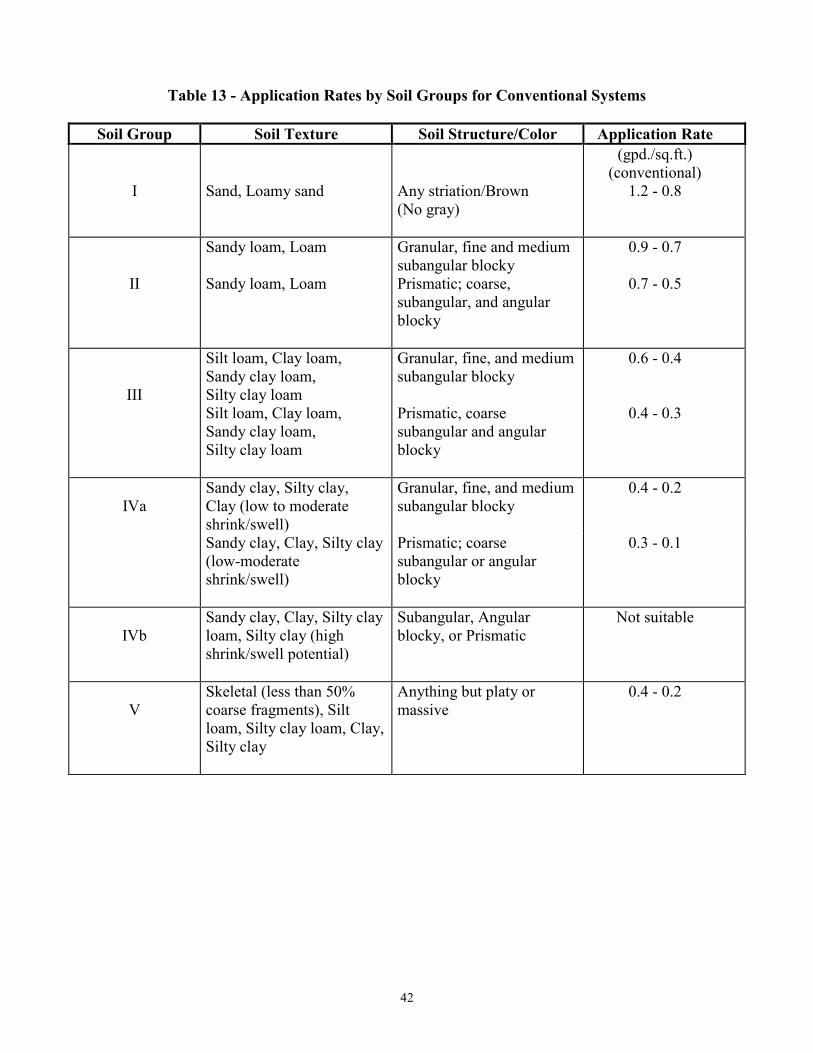
42
Table 13 - Application Rates by Soil Groups for Conventional Systems
Soil Group Soil Texture Soil Structure/Color Application Rate
I
Sand, Loamy sand
Any striation/Brown
(No gray)
(gpd./sq.ft.)
(conventional)
1.2 - 0.8
II
Sandy loam, Loam
Sandy loam, Loam
Granular, fine and medium
subangular blocky
Prismatic; coarse,
subangular, and angular
blocky
0.9 - 0.7
0.7 - 0.5
III
Silt loam, Clay loam,
Sandy clay loam,
Silty clay loam
Silt loam, Clay loam,
Sandy clay loam,
Silty clay loam
Granular, fine, and medium
subangular blocky
Prismatic, coarse
subangular and angular
blocky
0.6 - 0.4
0.4 - 0.3
IVa
Sandy clay, Silty clay,
Clay (low to moderate
shrink/swell)
Granular, fine, and medium
subangular blocky
0.4 - 0.2
Sandy clay, Clay, Silty clay
(low-moderate
shrink/swell)
Prismatic; coarse
subangular or angular
blocky
0.3 - 0.1
IVb
Sandy clay, Clay, Silty clay
loam, Silty clay (high
shrink/swell potential)
Subangular, Angular
blocky, or Prismatic
Not suitable
V
Skeletal (less than 50%
coarse fragments), Silt
loam, Silty clay loam, Clay,
Silty clay
Anything but platy or
massive
0.4 - 0.2
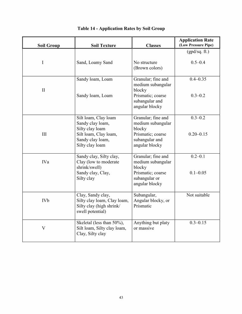
43
Table 14 - Application Rates by Soil Group
Soil Group
Soil Texture
Classes
Application Rate (Low Pressure Pipe)
I
Sand, Loamy Sand
No structure
(Brown colors)
(gpd/sq. ft.)
0.5–0.4
II
Sandy loam, Loam
Sandy loam, Loam
Granular; fine and
medium subangular
blocky
Prismatic; coarse
subangular and
angular blocky
0.4–0.35
0.3–0.2
III
Silt loam, Clay loam
Sandy clay loam,
Silty clay loam
Silt loam, Clay loam,
Sandy clay loam,
Silty clay loam
Granular; fine and
medium subangular
blocky
Prismatic; coarse
subangular and
angular blocky
0.3–0.2
0.20–0.15
IVa
Sandy clay, Silty clay,
Clay (low to moderate
shrink/swell)
Granular; fine and
medium subangular
blocky
0.2–0.1
Sandy clay, Clay,
Silty clay
Prismatic; coarse
subangular or
angular blocky
0.1–0.05
IVb
Clay, Sandy clay,
Silty clay loam, Clay loam,
Silty clay (high shrink/
swell potential)
Subangular,
Angular blocky, or
Prismatic
Not suitable
V
Skeletal (less than 50%),
Silt loam, Silty clay loam,
Clay, Silty clay
Anything but platy
or massive
0.3–0.15

44
19 CSR 20-3.070 Requirements for On-Site Waste
water Treatment System Inspectors/Evaluators
PURPOSE: This rule establishes criteria for
inclusion on the lists of those individuals licensed to
inspect or evaluate on-site wastewater treatment
systems for the purposes of real estate transactions.
PUBLISHER’S NOTE: The secretary of state has
determined that the publication of the entire text of the
material which is incorporated by reference as a portion
of this rule would be unduly cumbersome or expensive.
This material as incorporated by reference in this rule
shall be maintained by the agency at its headquarters and
shall be made available to the public for inspection and
copying at no more than the actual cost of reproduction.
This note applies only to the reference material. The
entire text of the rule is printed here.
(1) Applicability. The requirements and procedures
included in this rule apply to individuals qualified to
perform inspections and/or evaluations of existing on-site
wastewater treatment systems upon a request from a
lending institution, a prospective purchaser, the owner of
the property, a real estate agent, or a real estate broker.
(2) Definitions.
(A) “Administrative authority” shall mean the
department or local public health agencies, planning and
zoning commissions, county building departments, county
public works departments, sewer districts, and/or
municipalities that have authority to govern on-site
wastewater treatment systems.
(B) “Department” shall mean the Missouri Department
of Health and Senior Services.
C) “Lending institution” shall mean a bank, savings
and loan association, credit union, consumer credit lender,
mortgage banker, or any other association or institution,
which makes real estate loans.
(D) “Licensed individual” shall mean any person,
including staff of local administrative authorities, licensed
by the department, to inspect or evaluate an existing on-
site wastewater treatment system for the purposes of a
real estate transaction.
(E) “On-site wastewater treatment system (OWTS)”
shall mean any system handling, or treatment facility
receiving, domestic sewage which discharges three
thousand (3,000) gallons per day or less into a subsurface
soil absorption system or a single-family residence
lagoon.
(F) “Property owner” shall mean the person with the
legal right to possession of real estate.
(G) “Requesting party” shall mean a lending
institution, a prospective purchaser, the property owner, a
real estate agent, or a real estate broker who requests an
inspection or evaluation of an OWTS serving a property
that is the subject of a real estate transaction.
(3) An individual must be licensed with the department to
inspect or evaluate an existing OWTS upon the request
from a lending institution, which is providing either a
government loan or conventional loan, or from another
requesting party in connection with a real estate
transaction. If the inspection or evaluation determines
that the OWTS does not meet department standards, any
new construction, major modification, or major repair
must be conducted according to the standards set forth in
sections 701.025 through 701.059, RSMo, and any rules
promulgated thereunder or applicable local OWTS
ordinance.
(4) As deemed necessary by the department, an inspection
or evaluation of an OWTS will include a microbiological
test and other examination(s) of the private water supply
intended for potable use serving the same property as the
OWTS. In addition, the inspection or evaluation will
include an inspection of any visible portion of the water
supply construction, from the source to the storage vessel,
and may include review of the well drilling reports.
(5) If it is necessary to enter any adjoining property in the
course of an inspection or evaluation to properly make a
determination regarding the OWTS inspection/evaluation,
a licensed individual shall notify the owner of the
adjoining property and obtain permission before entry is
made.
(6) An individual must be licensed with the department to
perform inspections and evaluations of existing OWTS
for the purposes of a real estate transaction. To be
licensed with the department, an individual shall:
(A) Complete a basic installer training course
conducted by or approved by the department with a score
of seventy percent (70%) or higher;
(B) Complete a licensed inspector training course
conducted by or approved by the department with a score
of seventy percent (70%) or higher; and
(C) Complete the department’s licensing process
described in section (7) of this rule.
(7) Department’s Licensing Process.
(A) The license shall be issued to only one (1)
individual person and not to a company, firm, association,
or other group. The license is not transferable.
(B) To obtain a license from the department, an
individual must submit a completed application packet to
the department for approval. Completed application
packets shall be mailed to the Missouri Department of
Health and Senior Services, Attention: Fee Receipts, PO
Box 570, Jefferson City, MO 65102-0570.
(C) The application packet shall include the following:
1. The completed application form, Mo Form #1
(6-08), Application for Licensure, is incorporated by
reference in this rule and is available on the Internet at
www.dhss.mo.gov/Onsite or by contacting the department
45
at PO Box 570, Jefferson City, MO 65102-0570, (573)
751-6095. This rule does not incorporate any subsequent
amendments or additions;
2. Documentation of the successful completion of
both the basic installers training course and licensed
inspector training course; and
3. A check or money order made payable to the
Missouri Department of Health and Senior Services for
the nonrefundable-processing fee of ninety dollars ($90).
The processing fee may be waived for the staff of a local
administrative authority that has enacted local ordinances,
which include requirements for inspections of existing
OWTS that are at least equal to department standards.
(8) Department’s Renewal Licensing Process. An
individual’s license with the department shall expire
thirty-six (36) months from the month of issuance unless
the license has been revoked or surrendered.
(A) To renew their license with the department, an
individual must submit a renewal application packet to the
department for approval. Completed application packets
shall be mailed to the Missouri Department of Health and
Senior Services, Attention: Fee Receipts, PO Box 570,
Jefferson City, MO 65102-0570.
(B) The renewal application packet shall include:
1. The completed application form, Mo Form #2
(6-08), Application for Licensure Renewal, is
incorporated by reference in this rule and is available on
the Internet at www.dhss.mo.gov/Onsite or by contacting
the department at PO Box 570, Jefferson City, MO
65102-0570, (573) 751-6095. This rule does not
incorporate any subsequent amendments or additions;
2. A check or money order made payable to the
Missouri Department of Health and Senior Services for
the nonrefundable-processing fee of ninety dollars ($90).
The processing fee may be waived for the staff of a local
administrative authority that has enacted local ordinances,
which include requirements for inspections of existing
OWTS that are at least equal to department standards; and
3. Documentation of the applicant’s successful
completion, within the previous thirty-six (36) months of
the following minimum continuing education:
A. For individuals who are renewing their
license for the first time, at least twenty (20) hours of
department-approved continuing education units of which
at least eight (8) continuing education units shall meet
select department criteria; or
B. For individuals who are renewing their
license for the second or subsequent time, at least twelve
(12) hours of department-approved continuing education
units of which at least eight (8) continuing education units
shall meet select department criteria.
(C) Individuals submitting a renewal application more
than fifteen (15) calendar days after the previous license
expires shall pay a late charge of ten dollars ($10) in
addition to the ninety-dollar ($90) processing fee.
(D) License renewal applications will not be accepted
if received by the department more than forty-five (45)
calendar days after the previous license expires.
Individuals submitting license renewal applications more
than forty-five (45) calendar days after the expiration of
their license will be required to complete the initial
licensing process, including any department training
requirements for an initial license.
(9) A fifteen-dollar ($15) processing fee will be assessed
for duplicate and/or replacement license identification
cards.
(10) Standards of Practice for Licensed Individuals.
(A) A licensed individual shall:
1. Possess a current license with the department
before conducting any inspection or evaluation of an
OWTS;
2. Inspect or evaluate only those OWTS for which
requests have been made for the purposes of real estate
transactions. Investigations of complaints or alleged
violations of Chapter 701, RSMo, may only be made by
the department or a local administrative authority;
3. As part of an OWTS inspection or evaluation,
collect a water sample from a private water supply for
microbiological testing and inspect any visible portion of
the water supply construction, from the source to the
storage vessel;
4. Record their license number on all bids,
proposals, contracts, invoices, inspection reports,
evaluation reports, and other correspondence with the
requesting party or the department;
5. Apply department standards for all inspections
and evaluations of OWTS using the correct procedures
and forms to complete the inspection or the evaluation.
Combining inspection and evaluation procedures or forms
is not acceptable;
6. Document inspections and evaluations
accurately in writing on department-approved forms;
7. Clearly state any defect(s), if the OWTS is found
to be malfunctioning or otherwise not meeting department
standards;
8. Retain one (1) copy of the completed
documentation of the inspection or evaluation for at least
three (3) years and submit a copy to the department, the
local administrative authority, if applicable, the requesting
party, and the property owner;
9. Submit completed inspection/evaluation reports
to the department within thirty (30) calendar days of
completion, including water sample results if applicable;
and
10. Notify the property owner that he/she is not
obligated to contract for repair or re-inspection services
with the initial licensed individual if the OWTS has been
found to be malfunctioning or otherwise not meeting
department standards. However, this paragraph does not
46
preclude the licensed individual from offering these
services to the owner.
(11) The department may audit the work of a licensed
individual at any time to determine whether the standards
of practice, as defined by this rule, are being met. Failure
to adhere to department standards may be cause for
placement on probation, suspension, or revocation of the
license, or for mandatory successful completion of a
training course and/or testing as described in section (6)
of this rule. The audit may be an unannounced visit to the
property inspected or evaluated, or a visit during an
inspection or evaluation with or without prior
appointment with the licensed individual.
(12) A licensed individual may have his/her license
placed on probation, suspended, or revoked if the
individual:
(A) Fails an audit or refuses to participate in an audit;
(B) Fails to submit reports, submits false reports, or
allows another individual to use his/her license;
(C) Is convicted of a violation of any provisions of
sections 701.025 through 701.059, RSMo, or any rules
promulgated under these statutes;
(D) Has pled guilty or has been found guilty of an
infraction, misdemeanor, or felony involving
misrepresentation, fraud, or other crime relating to
activities of inspecting, evaluating, installing, repairing, or
otherwise associated with an OWTS;
(E) Directs or allows an unlicensed individual to
conduct any part of an inspection or evaluation of an
OWTS; or
(F) Fails to comply with the standards of practice
established in this rule.
(13) The suspension or revocation of an individual’s
license shall be served in writing by certified mail or
personal service to the affected individual or his/her
representative. The decision of the department may be
appealed to the Administrative Hearing Commission as
provided in Chapters 536 and 621, RSMo.
(14) Any individual whose license has been revoked may
not reapply for a license for at least one (1) year from date
of revocation, must complete the department’s training
requirements for licensure described in section (6) of this
rule, and complete the department’s licensing process as
described in section (7) of this rule.
(15) An individual may be permanently barred from
reapplying for a license if the individual:
(A) Has pled guilty or has been found guilty of an
infraction, misdemeanor, or felony involving
misrepresentation, fraud, or other crime relating to
activities associated with an OWTS; or
(B) Has his/her license revoked a second time within
five (5) years.
(16) No person without a valid license may conduct any
part of an inspection or evaluation of an OWTS, whether
on his/her own or under supervision of a person with a
valid license. Persons conducting inspections or
evaluations without the required license, or representing
themselves as licensed, are considered in violation of
section 701.053, RSMo, which is a class A misdemeanor.
AUTHORITY: section 701.033, RSMo Supp. 2008 and sections 701.046 and 701.051, RSMo 2000.* Emergency rule filed April 17, 1995,
terminated April 26, 1995. Original rule filed April 17, 1995, effective
Dec. 30, 1995. Rescinded and readopted: Filed Oct. 22, 2008, effective May 30, 2009.
*Original authority: 701.033, RSMo 1986, amended 1993, 1994, 1995, 2004; 701.046, RSMo 1994; and 701.051, RSMo 1994, amended 1997.
47
19 CSR 20-3.080 Requirements for Percolation
Testers, On-Site Soils Evaluators and Registered On-
Site Wastewater Treatment System Installers
PURPOSE: This rule establishes the criteria for
inclusion on the lists of those individuals qualified
to perform percolation tests and/or soils
morphology evaluations in determining soil
properties for on-site wastewater treatment
systems and for inclusion on the registered on-site
wastewater system installers list in accordance
with sections 701.025 through 701.059, RSMo.
PUBLISHER’S NOTE: The secretary of state has
determined that the publication of the entire text of
the material which is incorporated by reference as a
portion of the rule would be unduly cumbersome or
expensive. This material as incorporated by
reference in this rule shall be maintained by the
agency at its headquarters and shall be made
available to the public for inspection and copying at
no more than the actual cost of the reproduction.
This note applies only to the reference material. The
entire text of the rule is printed here.
(1) Applicability. The requirements and procedures
included in this rule apply to individuals qualified to
perform percolation tests and/or soil morphology
evaluations and installers who are seeking inclusion on
the department’s on-site wastewater treatment systems
professionals registry.
(2) Definitions.
(A) “Administrative authority” shall mean the
department or local public health agencies, planning and
zoning commissions, county building departments,
county public works departments, sewer districts, and/or
municipalities that have authority to govern individual
on-site wastewater treatment systems.
(B) “Advanced on-site wastewater treatment system
(OWTS) installer” shall mean an individual registered by
the department to install advanced OWTS as listed by the
department.
(C) “Basic on-site wastewater treatment system
(OWTS) installer” shall mean an individual registered by
the department to install basic OWTS as listed by the
department.
(D) “Department” shall mean the Missouri Department
of Health and Senior Services.
(E) “Installer” shall mean any individual, other than a
homeowner, who installs a system for their own personal
use, who alters, extends, repairs, or constructs an OWTS,
including but not limited to, excavating or earthmoving
work connected with the construction of an OWTS on
behalf of, or under contract with, the property owner.
(F) “Licensed professional engineer” shall mean any
person authorized pursuant to the provisions of Chapter
327, RSMo, to practice as a professional engineer in
Missouri, as the practice of engineering is defined in section
327.181, RSMo.
(G) “On-site soil evaluator” shall mean individuals
including soil scientists, licensed professional engineers, and
registered geologists meeting the requirements of this rule.
(H) “On-site wastewater treatment system (OWTS)” shall
mean any system handling, or treatment facility receiving,
domestic sewage which discharges three thousand (3,000)
gallons per day or less into a subsurface soil absorption
system or a single-family residence lagoon.
(I) “Registered geologist” shall mean any person
authorized pursuant to the provisions of Chapter 256, RSMo,
to practice as a registered geologist in Missouri, as defined
in section 256.453(10), RSMo.
(J) “Soil morphology evaluation” shall mean the method
of testing or evaluating absorption qualities of the soil by
physical examination of the soil’s color, mottling, texture,
structure, topography, and hill-slope position.
(K) “Soil scientist” shall mean a person that has
successfully completed at least fifteen (15) semester credit
hours of soils science course work, including at least three
(3) hours of course work in soil morphology and
interpretations.
(3) An individual must be registered with the department to
conduct any part of a percolation test or soil morphology
evaluation in which results are intended for use in the design
or installation of an OWTS according to the standards set
forth in sections 701.025 through 701.059, RSMo, and 19
CSR 20-3.060.
(A) Percolation Tests. To register with the department to
conduct percolation tests, an individual shall:
1. Successfully complete a training course conducted by
or approved by the department, which shall include, at a
minimum, course work, field work, a written examination,
and a practical examination; or
2. Meet the definition of an on-site soil evaluator,
licensed professional engineer, or registered geologist; and
3. Complete the department’s registration process
described in section (5) of this rule.
(B) Soil Morphology Evaluations. To register with the
department to perform soils morphology evaluations, an
individual shall:
1. Meet the definition of a soil scientist with at least
fifteen (15) semester credit hours of soils science course
work, including at least three (3) hours of course work in
soil morphology and interpretations; or
2. Meet the definition of a licensed professional
engineer or registered geologist with at least ten (10)
semester credit hours of soils science course work, including
at least three (3) hours of course work in soil morphology
and interpretations; and
3. Complete a written and field test conducted by or
approved by the department with a score of seventy percent
(70%) or higher on all sections of each examination; and
4. Complete the department’s registration process
48
described in section (5) of this rule.
(4) An individual must be registered with the department,
with the exception of a homeowner meeting the
requirements of section 701.055, RSMo, to install an
OWTS. Only installers registered as advanced OWTS
installers shall install systems listed by the department as
advanced OWTS.
(A) Basic OWTS Installer. To register with the
department as a basic OWTS installer, an individual
shall:
1. Complete a basic installer training course
conducted by or approved by the department with a score
of seventy percent (70%) or higher; and
2. Complete the department’s registration process
described in section (5) of this rule.
(B) Advanced OWTS Installer. To register with the
department as an advanced OWTS installer, an
individual shall:
1. Possess a basic OWTS installer’s registration in
good standing;
2. Complete an advanced OWTS installer training
course conducted by or approved by the department with
a score of seventy percent (70%) or higher; and
3. Complete the department’s registration process
described in section (5) of this rule.
(5) Department’s Registration Process.
(A) To register with the department, an individual
must submit a completed application packet to the
department for approval. Completed application packets
shall be mailed to the Missouri Department of Health and
Senior Services, Attention: Fee Receipts, PO Box 570,
Jefferson City, MO 65102-0570.
(B) The application packet shall include the following:
1. The completed application form, Mo Form #1 (6-
08), Application for Registration, which is incorporated
by reference in this rule and is available on the Internet at
www.dhss.mo.gov/Onsite or by contacting the
department at PO Box 570, Jefferson City, MO 65102-
0570, (573) 751-6095. This rule does not incorporate any
subsequent amendments or additions;
2. For on-site soil evaluators, mail an original
transcript from the college or university attended directly
from the registrar to the Missouri Department of Health
and Senior Services, Attention: Bureau of Environmental
Regulation and Licensure, PO Box 570, Jefferson City,
MO 65102-0570. If requested, provide course
descriptions from the college or university attended to
verify the nature of the course work;
3. For percolation testers and on-site soil evaluators,
provide proof of licensure as a professional engineer or
certificate of registration by the Board of Geologist
Registration indicating the registrant is in good standing,
if applicable; and
4. A check or money order made payable to the
Missouri Department of Health and Senior Services for the
nonrefundable-processing fee of ninety dollars ($90).
(6) Department’s Temporary and Probationary Registration
Process.
(A) Upon completion of the department’s registration
process described in section (5) of this rule, the department
may issue a one (1)-time temporary basic OWTS installer
registration, valid for no more than one hundred eighty (180)
calendar days for work in a specific county or counties. The
temporary basic OWTS registration will be converted to a
basic OWTS installer registration upon completion of a
training course conducted by or approved by the department.
Failure to complete the training or the department’s
registration process will result in termination of the
individual’s temporary basic OWTS installer registration.
(B) The department may issue a probationary basic OWTS
installer registration for work in a specific county or
counties. This registration will be valid for a specific period
of time, as determined by the department, and will be
dependent on the registered individual meeting and
maintaining specific requirements as established by the
department and completing the department’s registration
process as described in section (5) of this rule.
(7) Department’s Renewal Registration Process. An
individual’s registration with the department shall expire
thirty-six (36) months from its effective date unless the
registration has been revoked or surrendered.
(A) To renew his or her registration with the department,
an individual must submit a renewal application packet to
the department for approval. Completed application packets
shall be mailed to the Missouri Department of Health and
Senior Services, Attention: Fee Receipts, PO Box 570,
Jefferson City, MO 65102-0570.
(B) The renewal application packet shall include:
1. The completed application form, Mo Form #2A (6-
08), Application for Registration Renewal, which is
incorporated by reference in this rule and is available on the
Internet at www.dhss.mo.gov/Onsite or by contacting the
department at PO Box 570, Jefferson City, MO 65102-0570,
(573) 751-6095. This rule does not incorporate any
subsequent amendments or additions;
2. A check or money order made payable to the
Missouri Department of Health and Senior Services for the
nonrefundable-processing fee of ninety dollars ($90); and
3. Documentation of the applicant’s successful
completion, within the previous thirty-six (36) months, of
the following minimum continuing education:
A. For on-site soil evaluators, percolation testers, and
basic and advanced OWTS installers who are renewing their
registration for the first time, at least twenty (20) hours of
department-approved continuing education units of which at
least eight (8) continuing education units shall meet select
department criteria;
49
B. For on-site soil evaluators and advanced
OWTS installers who are renewing their registration for
the second or subsequent time, at least twelve (12) hours
of department-approved continuing education units of
which at least eight (8) continuing education units shall
meet select department criteria related to their OWTS
profession; or
C. For basic OWTS installers and percolation
testers who are renewing their registration for the second
or subsequent time, at least eight (8) hours of
department-approved continuing education units.
(C) Individuals submitting a renewal application more
than fifteen (15) calendar days after the previous
registration expires shall pay a late charge of ten dollars
($10) in addition to the ninety dollar ($90) registration-
processing fee.
(D) Registration renewal applications will not be
accepted if received by the department more than forty-
five (45) calendar days after the previous registration
expires. Individuals submitting registration renewal
applications more than forty-five (45) calendar days after
expiration of their registration will be required to
complete the initial registration process, including any
department training requirements for an initial
registration.
(8) A fifteen-dollar ($15) processing fee will be assessed
for duplicate and/or replacement registration
identification cards.
(9) Standards of Practice for Percolation Testers, On-Site
Soil Evaluators, and OWTS Installers.
(A) A percolation tester or on-site soil evaluator shall:
1. Possess a current registration with the department
before performing any activities related to a percolation
test or soil morphology evaluation;
2. Record their registration number on all bids,
proposals, contracts, invoices, percolation test reports,
soil morphology evaluation reports, and other
correspondence with the property owner or
administrative authority;
3. Provide true and accurate information on any
application, percolation test report, soil morphology
evaluation report, and any other OWTS documentation;
4. Maintain a current address and phone number
with the department and submit any address or phone
number changes to the department in writing within
thirty (30) calendar days of the change taking place;
5. Conduct percolation tests in accordance with
section (2) of 19 CSR 20-3.060; and
6. Conduct site/soil morphology evaluations in
accordance with the standards detailed in sections (2)
and (7) of 19 CSR 20-3.060. Specifically, the on-site
soil evaluator shall:
A. Evaluate the nine (9) items listed in paragraphs
(2)(A)2. through 10. of 19 CSR 20-3.060;
B. Evaluate and classify six (6) site factors listed in
subsection (7)(C) of 19 CSR 20-3.060, as suitable,
provisionally suitable, or unsuitable according to subsections
(7)(E) through (L) of 19 CSR 20-3.060;
C. Include a diagram showing location and extent of
the area(s) evaluated;
D. Make recommendations regarding the use and
effectiveness of water lowering systems when there is
evidence of a high water table; and
E. Based on subsection (7)(M) and Tables 13 and 14
of 19 CSR 20-3.060, for horizons that are not classified as
unsuitable, assign a conventional soil loading rate for each
horizon and assign an alternative soil loading rate for each
horizon to a depth of at least twelve inches (12") below the
likely depth of an alternative system.
(B) A registered basic OWTS installer or a registered
advanced OWTS installer shall:
1. Possess a current basic OWTS installer registration or
advanced OWTS installer registration with the department
before beginning construction of any OWTS;
2. Record their registration number on all bids,
proposals, contracts, invoices, permit application
construction drawings, and other correspondence with the
property owner or administrative authority;
3. Provide true and accurate information on any
application and any other OWTS documentation;
4. Notify the administrative authority if their
involvement as the registered installer with the permit
application and OWTS changes;
5. Begin the construction of an OWTS only after
obtaining approval from the administrative authority, unless
approval is not required;
6. Construct the OWTS meeting the construction
standards and permit criteria required by sections 701.025
through 701.059, RSMo, and any rule adopted thereunder or
the more stringent requirements of the administrative
authority, if applicable;
7. Construct the OWTS that has been authorized by the
administrative authority for the specific location identified in
the application;
8. Be present at the construction site during construction
and supervise all construction activities;
9. Provide required notice and an opportunity for
inspection prior to completion of the OWTS installation as
required by the administrative authority;
10. Submit complete and accurate “certification without
on-site inspection form,” when requested;
11. Not create or increase a health or safety hazard,
nuisance condition, or surface water or groundwater
contamination when constructing, repairing, modifying, or
troubleshooting an OWTS; and
12. Maintain a current address and phone number with
the department and submit any address or phone number
changes to the department in writing within thirty (30)
calendar days of the change taking place.
(10) The department may audit the work of a percolation
50
tester, on-site soil evaluator, registered basic OWTS
installer, or registered advanced OWTS installer at any
time to determine whether the standards of practice, as
defined by this rule, are being met. Failure to adhere to
department standards may be cause for placement on
probation, suspension, or revocation of the registration,
or for mandatory successful completion of a training
course and/or testing as described in sections (3) and (4)
of this rule. The audit may be an unannounced visit to
the property on which the percolation test, soil
morphology examination, or OWTS installation was
conducted, which may include an independent soil
percolation test or soil morphology examination, or a
visit within the period of a soil percolation test, soil
morphology examination, or OWTS installation with or
without prior appointment with the registered individual.
(11) A percolation tester, on-site soil evaluator,
registered basic OWTS installer, or registered advanced
OWTS installer may have their registration placed on
probation, suspended, or revoked if the individual:
(A) Fails to maintain any professional license
necessary for registration as a percolation tester or on-
site soil evaluator;
(B) Fails an audit or refuses to participate in an audit;
(C) Fails to submit reports, submits false reports, or
allows another individual to use his/her registration;
(D) Is convicted of a violation of any provisions of
sections 701.025 through 701.059, RSMo, or any rules
promulgated under these statutes;
(E) Has pled guilty or has been found guilty of an
infraction, misdemeanor, or felony involving
misrepresentation, fraud, or other crime relating to
activities of percolation testing, soil morphology
evaluations, installing, repairing, inspecting, or otherwise
associated with an OWTS;
(F) Directs or allows an unregistered individual to
conduct a percolation test or soil morphology
examination;
(G) Directs or allows an unregistered individual to
install an OWTS without direct supervision; or
(H) Fails to comply with the standards of practice
established by this rule.
(12) The suspension or revocation of a percolation
tester’s, on-site soil evaluator’s, or OWTS installer’s
registration shall be served in writing by certified mail or
personal service to the affected individual or his/her
representative. The decision of the department may be
appealed to the Administrative Hearing Commission as
provided in Chapters 536 and 621, RSMo.
(13) Any individual whose registration has been revoked
may not reapply for registration for at least one (1) year
from date of revocation, and must complete the
department’s training requirements for registration
described in sections (3) and (4) of this rule and
complete the department’s registration process as described
in section (5) of this rule.
(14) An individual may be permanently barred from
reapplying for registration if the individual:
(A) Has pled guilty or has been found guilty of an
infraction, misdemeanor, or felony involving
misrepresentation, fraud, or other crime relating to activities
associated with an OWTS; or
(B) Has his/her registration revoked a second time within
five (5) years.
(15) No person without a valid registration may conduct any
part of a percolation test or soil morphology evaluation for
an OWTS, whether on their own or under supervision of a
person with a valid registration. Persons conducting
percolation tests or soil morphology evaluations without the
required registration, or representing themselves as
registered, are considered in violation of section 701.053,
RSMo, which is a class A misdemeanor.
(16) No person as defined in section 701.025, RSMo, may
authorize, permit, or knowingly allow a percolation test or
soil morphology evaluation for an OWTS by an unregistered
individual or the installation of an OWTS by an unregistered
individual other than the homeowner.
AUTHORITY: section 701.033, RSMo Supp. 2008 and section 701.040, RSMo 2000.*
Emergency rule filed April 17, 1995, terminated April 26, 1995. Original rule filed
April 17, 1995, effective Dec. 30, 1995. Emergency amendment filed Sept. 2, 2004,
effective Sept. 12, 2004, expired March 10, 2005. Rescinded and readopted: Filed
Sept. 2, 2004, effective Feb. 28, 2005. Amended: Filed Oct. 22, 2008, effective May 30,
2009.
*Original authority: 701.033, RSMo 1986, amended 1993, 1994, 1995, 2004 and
701.040, RSMo 1994.

51
Local Public Health Agency (LPHA) contact information:
http://health.mo.gov/living/lpha/lphas.php
Department of Health and Senior Services
Clark Scotland
Knox Lewis
Marion
Mo
ntg
om
ery
G
asco
na
de
Schuyler Putnam
Adair Sullivan
Linn Macon Shelby
Ralls Monroe
Mercer
Grundy
Randolph
Livingston
Chariton
Daviess
Worth
Caldwell Clinton
Nodaway Atchison
Holt
Andrew
Buchanan
Platte Clay Ray
Carroll Pike
Audrain Lincoln
Warren St. Charles
St. Louis
Osage Franklin
Jefferson
Ste. Genevieve
St. Francois Perry
Jackson
Lafayette Saline Howard
Pettis
Cole
Callaway
Boone
Cooper
Moniteau
Morgan
Miller Maries
Phelps Crawford Washington
Pulaski
Cass Johnson
Bates
Henry Benton
Vernon
St. Clair
Hickory Camden
Dent
Iron
Bo
llin
ge
r Cape Girardeau
Scott
Mississippi Stoddard
New Madrid
Dunklin
Barton
Jasper
Newton
McDonald
Cedar Polk
Dade
Barry
Christian
Greene Wright
Dallas Laclede
Taney
Douglas
Texas
Ozark Howell
Shannon
Carter
Oregon Ripley Butler
Wayne
Pemiscot
ON-SITE SEWAGE AUTHORITY
State Administered Counties – Contact
Onsite Sewage Program
Contract Counties (State Standards)
Contact Local Public Health Agency (LPHA)
Ordinance Counties
Contact LPHA or other Local Authority 11/2017
In state administered counties contact:
Onsite Wastewater Treatment Program 930 Wildwood Dr.
Jefferson City, MO 65102 (573) 751-6095
(573) 526-7377 Fax
Harrison
Gentry
DeKalb
Reynold Madison
Lawrencee
Webster
Stone
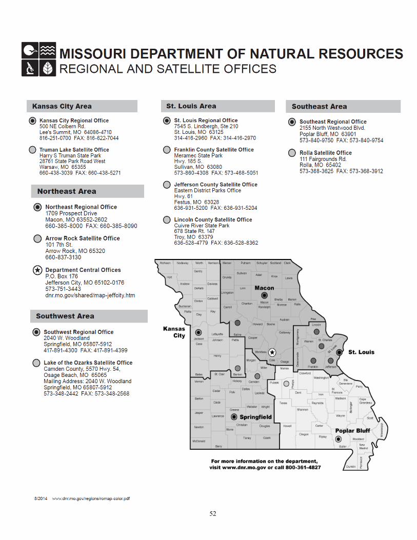
52