
Gordon Wetzstein Stanford University · Logistics! • HW3 is probably the longest homework, so get...
49
Head Mounted Display Optics I Gordon Wetzstein Stanford University EE 267 Virtual Reality Lecture 7 stanford.edu/class/ee267/
Transcript of Gordon Wetzstein Stanford University · Logistics! • HW3 is probably the longest homework, so get...
Head Mounted Display Optics I!
Gordon Wetzstein!Stanford University!
!
EE 267 Virtual Reality!
Lecture 7!stanford.edu/class/ee267/!
!

Logistics!
• HW3 is probably the longest homework, so get started asap if you have not done so already!
• What is MAR (minimum angle of resolution)? !
Conflicting definitions of whether it’s the visual angle of 1 pixel or 1 cycle (=2 pixels) – for consistency, we use the same definition as in Guenther et al., which is 2 pixels!!
• all hardware for HW4 will be given out in lab/office hours on Friday, 10-11:30am, Packard 001!

Lecture Overview!
1. stereo rendering for HMDs!2. lens distortion correction using GLSL!

All Current-generation VR HMDs are “Simple Magnifiers”!
1. Stereo Rendering for HMDs!

Image Formation!
HMD!
lens!
Side View!
micro display!

Image Formation!
HMD!
lens!
Side View!
deyeeye relief!
micro display!
f
d '
h '
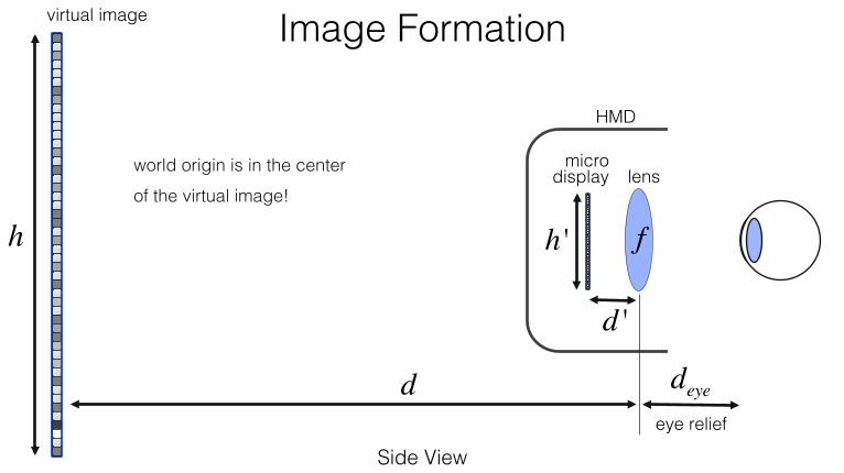
Image Formation!
HMD!
virtual image!
Side View!
d
h
deyeeye relief!
lens!micro
display!
f
d '
h '
world origin is in the center of the virtual image!!

Image Formation!
HMD!
virtual image!
Side View!
d
1d+ 1d '
= 1f
⇔ d = 11f− 1d '
Gaussian thin lens formula:!
h
deyeeye relief!
lens!micro
display!
f
d '
h '
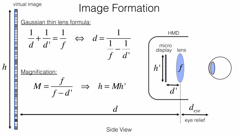
Image Formation!
HMD!
virtual image!
Side View!
d
1d+ 1d '
= 1f
⇔ d = 11f− 1d '
Gaussian thin lens formula:!
Magnification:!
M = ff − d '
⇒ h = Mh '
h
deyeeye relief!
lens!micro
display!
f
d '
h '
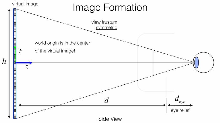
Image Formation!virtual image!
Side View!
d
h
eye relief!
deye
view frustum symmetric!
z
yworld origin is in the center of the virtual image!!

Image Formation!virtual image!
Side View!
d
h
eye relief!
deye
view frustum symmetric! near
clipping plane!
z
y

Image Formation!virtual image!
Side View!
d
h
eye relief!
deye
view frustum symmetric!
zneartop!
bottom!
near clipping plane!
z
y

Image Formation!virtual image!
Side View!
d
h
eye relief!
deye
view frustum symmetric!
zneartop!
bottom!
similar triangles:!near
clipping plane!
top = znearh
2 d + deye( )
bottom = −znearh
2 d + deye( )

Image Formation!
Top View!eye relief!
deye
ipd!
d 'w '
HMD!

Image Formation – Left Eye!
HMD!
Top View!
deyeeye relief!
w '2
ipd/2!

HMD!
virtual image!
Top View!
d
w1
deyeeye relief!
w2
ipd/2!
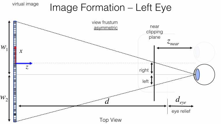
Image Formation – Left Eye!
z
x

HMD!
virtual image!
Top View!
d
w1
deyeeye relief!
w2
w1 = Mipd2
w2 = Mw '− ipd2
⎛⎝⎜
⎞⎠⎟
ipd/2!
Image Formation – Left Eye!
z
x

virtual image!
Top View!
deye relief!
deye
view frustum asymmetric!
znear
near clipping plane!
w1
w2
Image Formation – Left Eye!
z
x
virtual image!
Top View!
deye relief!
deye
view frustum asymmetric!
znear
right!
left!
near clipping plane!
w1
w2
Image Formation – Left Eye!
z
x

virtual image!
Top View!
deye relief!
deye
view frustum asymmetric!
znear
right!
left!
similar triangles:!
right = znearw1
d + deye
left = −znearw2
d + deye
near clipping plane!
w1
w2
Image Formation – Left Eye!

virtual image!
Top View!
deye relief!
deye
view frustum asymmetric!
w1
w2
Image Formation – Right Eye!
w1 = Mipd2
w2 = Mw '− ipd2
⎛⎝⎜
⎞⎠⎟
z
x

virtual image!
Top View!
deye relief!
deye
view frustum asymmetric!
znearright!
left!
similar triangles:!
right = znearw2
d + deye
left = −znearw1
d + deyew1
w2
Image Formation – Right Eye!

View Matrix - Lookat !
Top View!
d
h
eye relief!
deye
center point (right eye)!
center point (right eye)!
eye position (right eye)!
eye position (left eye)!
ipd!
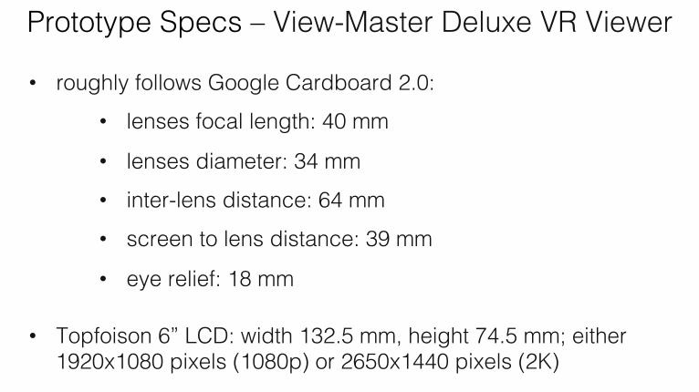
Prototype Specs – View-Master Deluxe VR Viewer!
• roughly follows Google Cardboard 2.0:!• lenses focal length: 40 mm!
• lenses diameter: 34 mm!• inter-lens distance: 64 mm!• screen to lens distance: 39 mm!
• eye relief: 18 mm!!
• Topfoison 6” LCD: width 132.5 mm, height 74.5 mm; either 1920x1080 pixels (1080p) or 2650x1440 pixels (2K)!

Image Formation!
• use these formulas to compute the perspective matrix in WebGL!
• you can use:! THREE.Matrix4().makePerspective(left,right,top,bottom,near,far) THREE.Matrix4().lookAt(eye,center,up)
!• that’s all you need to render stereo images on the HMD!

Image Formation for More Complex Optics!
• especially important in free-form optics, off-axis optical configurations & AR!
• use ray tracing – some nonlinear mapping from view frustum to microdisplay pixels!
• much more computationally challenging & sensitive to precise calibration; our HMD and most magnifier-based designs will work with what we discussed so far!

All lenses introduce image distortion, chromatic aberrations, and other artifacts – we need to correct
for them as best as we can in software!!
2. Lens Distortion Correction!
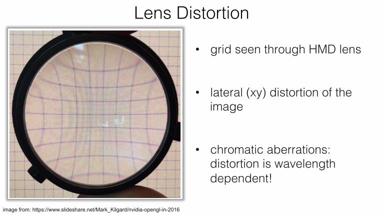
image from: https://www.slideshare.net/Mark_Kilgard/nvidia-opengl-in-2016
• grid seen through HMD lens!
• lateral (xy) distortion of the image!
• chromatic aberrations: distortion is wavelength dependent!!
Lens Distortion!

Pincussion Distortion!
Lens Distortion!
Barrel Distortion!
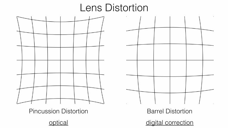
Pincussion Distortion!optical!
Lens Distortion!
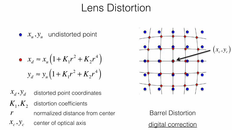
Barrel Distortion!digital correction!

Lens Distortion!
image from: https://www.slideshare.net/Mark_Kilgard/nvidia-opengl-in-2016

Lens Distortion!
xu , yu undistorted point!
Lens Distortion!
Barrel Distortion!digital correction!
xd ≈ xu 1+ K1r2 + K2r
4( )yd ≈ yu 1+ K1r
2 + K2r4( )
xu , yu undistorted point!
rxc , yc center of optical axis!
xc , yc( )
normalized distance from center!distortion coefficients!K1,K2
distorted point coordinates!xd , yd
Lens Distortion!
xd ≈ xu 1+ K1r2 + K2r
4( )yd ≈ yu 1+ K1r
2 + K2r4( )
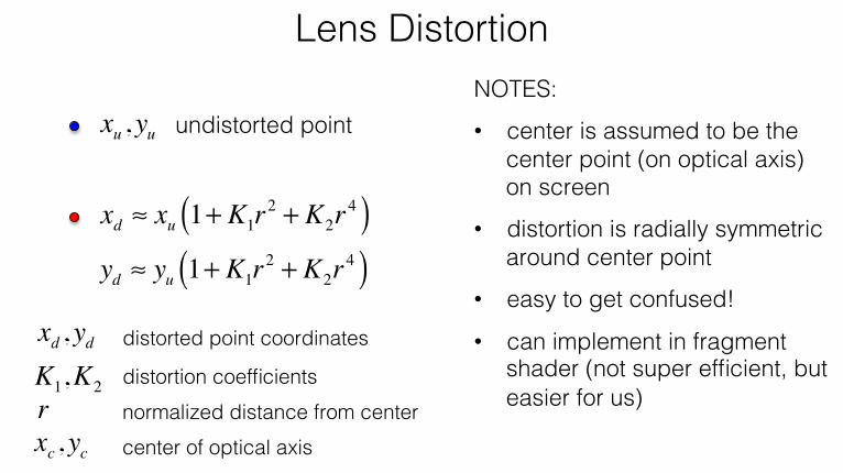
xu , yu undistorted point!NOTES:!• center is assumed to be the
center point (on optical axis) on screen!
• distortion is radially symmetric around center point !
• easy to get confused!!
• can implement in fragment shader (not super efficient, but easier for us) !r
xc , yc center of optical axis!normalized distance from center!distortion coefficients!K1,K2
distorted point coordinates!xd , yd

Normalizing r!
xd ≈ xu 1+ K1r2 + K2r
4( )yd ≈ yu 1+ K1r
2 + K2r4( )
xu , yu undistorted point!
Calculate in metric units, e.g. mm. Need physical size of the pixels of your screen for this!!
r!
r! 2 = xu − xc( )2 + yu − yc( )2xc , yc
un-normalized radial distance from center:!
center!

Normalizing r!virtual image!
Side View!
d
r!
view frustum symmetric!
r = r!
din mm
mm⎡⎣⎢
⎤⎦⎥
distance of a pixel from center point in mm!d distance to lens in mm!! r normalized, unit-less distance !
that we use for distortion! !
r!

Lens Distortion – Center Point!!
Top View!
d
h
eye relief!
deye
right eye!
xc , yc
xc , yc
left eye!
ipd!

Lens Distortion Correction Example!
stereo rendering without lens distortion correction!
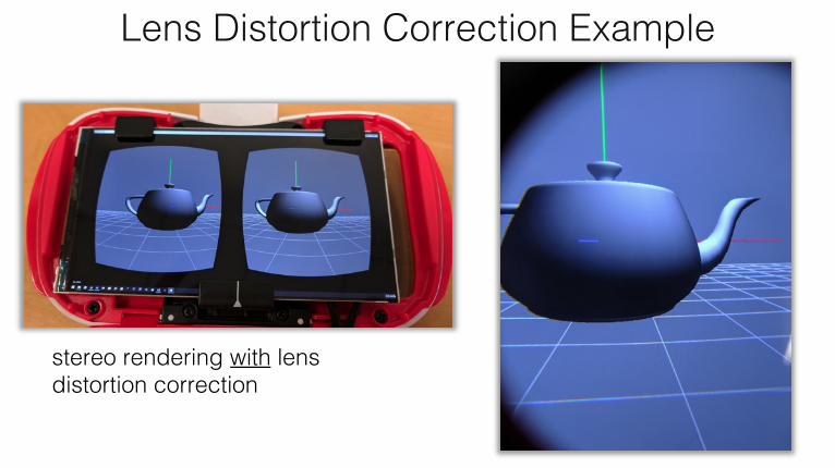
Lens Distortion Correction Example!
stereo rendering with lens distortion correction!

How to Render into Different Parts of the Window?!• WebGLRenderer.setViewport(x,y,width,height)
• x,y lower left corner; width, height viewport size !
(x1,y1) width1
height1
height2
height3
width3
width2
(x3,y3)
(x2,y2)

Microdisplays!

Liquid Crystal Display (LCD) - Subpixels!w
ikip
edia!
TN subpixels!IP
S!S-
IPS!
IPS!

wik
iped
ia!
LCD!
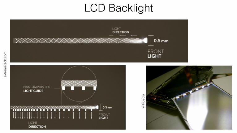
LCD Backlight!ex
trem
etec
h.co
m!
wik
iped
ia!
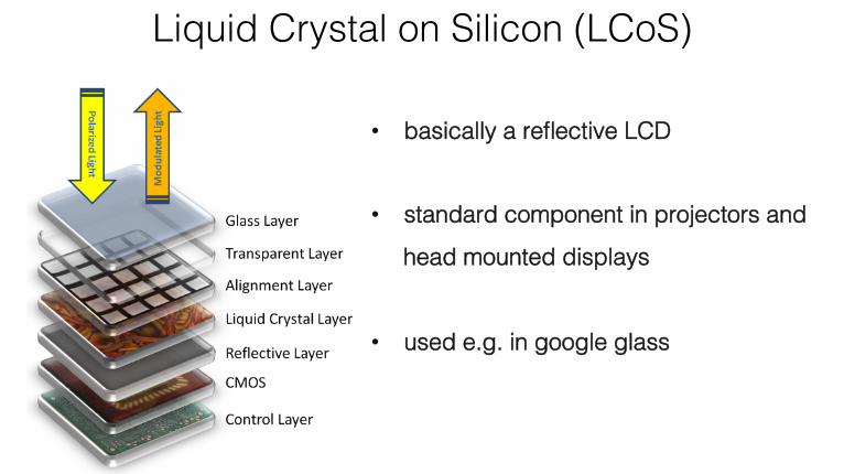
Liquid Crystal on Silicon (LCoS)!
• basically a reflective LCD!
• standard component in projectors and
head mounted displays!
• used e.g. in google glass!

Organic Light Emitting Diodes (OLED)!
light
rabb
it.co
.uk!

Digital Micromirror Device (DMD)!
• developed by Texas Instruments!
• MEMS device!
• binary states (e.g. +/- 10
degrees)!
• gray-level through pulse width modulation (PWM)!
Texas Instruments!

B. T. Schowengerdt, R. Johnston, C.D. Melville, E.J. Seibel. 3D Displays Using Scanning Laser Projection.
SID 2012. !
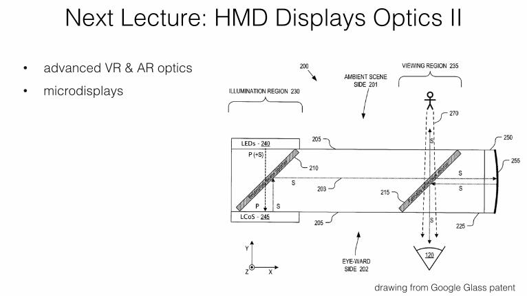
Next Lecture: HMD Displays Optics II!
• advanced VR & AR optics!• microdisplays!
drawing from Google Glass patent!