Good Solid Modeling Bad FEA
5
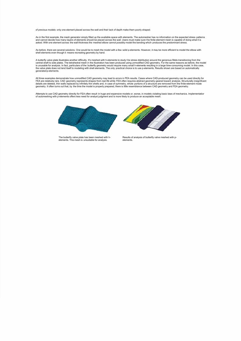
Good Solid Modeling, Bad FEA By: PAUL KUROWSKI President, Acom Consulting,Toronto, Ontario, Canada Solid modeling is great for visualizing ideas but it's often misapplied in finite-element analysis. One of the latest methods of slashing development time is to use t he 3D models that CAD users create as a basis f or finite-element analysis. In a perfect world, performing finite-element analysis on these models directly, rather than recreating data for this purpose, lets analysts concentrate more on analysis and less on syntax. Solids appear to be a wise choice as a basis for FEA because FE meshing can sometimes take place directly on CAD geometry without modifications. The literature abounds with examples of engineers doing exactly this. In real life, however, the interface between 3D CAD and FEA is seldom that simple. Solid CAD geometry almost always requires extensive modifications before it is suitable for meshing with finite elements. There also are occasions when solid CAD geometry is completely inappropriate for finite-element models. Successful interfacing requires time, care, and an understanding of inherent limitations. A f ew practical examples demonstrate why using unmodified CAD geometry for FEA can lead to erroneous results. There was no user intervention in generating a cooling-fin model built with h- elements. Unfortunately, default settings of an automatic mesh generator placed only one element across the fin thickness at the base where one would expect the highest stresses. To make matters worse, elements at t he fin base are poorly shaped. The meshed model produces meaningless and potentially dangerous results. Maximum averaged Von Mises stress equals 10,600 psi. Part 2: A Cooling Fin Consider the task of examining stresses at the vertical base of a horizontal cooling fin after applying bending loads to its edge. The CAD geometry for the fin and a portion of the base plate are exported to an FEA program as a solid and meshed using default parameters in t he automesher. An accompanying illustration shows the meshed model and resulting contour plot. But the mesh is not suitable for analysis and results are erroneous. What went wrong? Automeshing is a purely geometric function. The mesh generator simply fills up the available space with elements because it knows nothing about the expected stress pattern. As a result, it places one or two elements across the fin thickness, many of t hem poorly shaped by a lack of depth. Considering the kind of elements used (second-order subparametric h-elements), one or even two elements are insufficient to model stress distribution where the fin meets t he base. The mesh is incapable of modeling the stress pattern that will develop in the real structure. This is not a fault of the automesher. Even the best automatic mesh generators provide no assurance of a good mesh. It's the analyst's responsibility to make sure the mesh can model a stress pattern according to the laws of mechanics. Several elements are required across the thickness to accurately model bending. However, meshing with greater density would call for a large number of small elements making a prohibitively large FE model. This means the solid CAD geometry is practically unsuitable for meshing with solid h-elements. Furthermore, insisting on solid CAD geometry locks analysts into using solid elements. The only choice short of running a huge model is to use p-elements which can model bending even with only one element across the fin thickness. However, p-elements produce a problem which was masked before by the low density of h-elements. The CAD-produced geometry contains reentrant corners, those with more than 180° internal angles, without fillets. A theoretically infinite stress occurs at the corners. P-elements try to model these stresses by increasing the polynomial order of their shape functions. The results reported by a p-element model with singularity depends on the user-required accuracy. As users request greater solution accuracy, the solver responds by increasing the p-order used by elements around the corner. The model reports higher stresses with each increase in p-order. This continues until the solver assigns the highest p-order allowed. Should the user reduce the element size, the situation still repeats itself. Stress in reentrant corners will never converge to a finite value. In fact, results reported by the model in t he illustration are close to results from a shell model discussed later only by coincidence. Had the user employed smaller p-elements or requested a lower convergence error, or both, the model would have reported much higher stresses. Users must modify CAD-supplied geometry to deal with the inherent sensitivity of p-elements to singularities. For example, users may decide to add small f illets which would always exist in the real structure. The illustration Fin with f illets shows results from a p-element model with added fillets. Alternatively, when looking only for the highest stress, one might analyze a 2D plane strain slice from the middle of the fin, as it appears in the close-up. Of course, this requires modifying the CAD geometry. Another way around the problem of singularities is to recreate the geometry in the FEA program for use with shell elements as in t he illustration
-
Upload
download2005 -
Category
Documents
-
view
221 -
download
0
Transcript of Good Solid Modeling Bad FEA

8/8/2019 Good Solid Modeling Bad FEA
http://slidepdf.com/reader/full/good-solid-modeling-bad-fea 1/5

8/8/2019 Good Solid Modeling Bad FEA
http://slidepdf.com/reader/full/good-solid-modeling-bad-fea 2/5

8/8/2019 Good Solid Modeling Bad FEA
http://slidepdf.com/reader/full/good-solid-modeling-bad-fea 3/5

8/8/2019 Good Solid Modeling Bad FEA
http://slidepdf.com/reader/full/good-solid-modeling-bad-fea 4/5
8/8/2019 Good Solid Modeling Bad FEA
http://slidepdf.com/reader/full/good-solid-modeling-bad-fea 5/5