
Good Service Practices and Installation of Room Air ...
182
TECHNICIANS HANDBOOK i Good Service Practices and Installation of Room Air-conditioners with HCFC–22 and Flammable Refrigerants TECHNICIANS HANDBOOK Published by
Transcript of Good Service Practices and Installation of Room Air ...

TECHNICIANS HANDBOOK i
Good Service Practices and Installation of Room Air-conditioners with HCFC–22 and Flammable Refrigerants TECHNICIANS HANDBOOK
Published by

GOOD SERVICE PRACTICES AND INSTALLATION OF ROOM AIR-CONDITIONERS WITH HCFC–22 AND FLAMMABLE REFRIGERANTSii
Financially supported under:Multilateral Fund (MLF) to the Montreal Protocol
Implemented by:The Ozone Cell of the Ministry of Environment, Forests and Climate Change (MoEF&CC),Government of India, in cooperation with the Government of Germany represented by Deutsche Gesellschaft für Internationale Zusammenarbeit (GIZ) GmbH and United Nations Environment Programme (UNEP)
Published by:Deutsche Gesellschaft fürInternationale Zusammenarbeit (GIZ) GmbH
Registered offi cesBonn and EschbornDag-Hammarskjöld-Weg 1-565760 Eschborn, GermanyT +49 61 96 79-1022F +49 61 96 79-80 1022E [email protected] www.giz.de/proklima
GIZ – Proklima InternationalDeutsche Gesellschaft fur Internationale Zusammenarbeit (GIZ) GmbHSecond Floor, B - 5/2, Safdarjung Enclave, New Delhi – 110 029, India
Programme Manager:Bernhard Siegele ([email protected])
Authors:Prof. R.S. Agarwal, Ankur Khandelwal, C J Mathew and Ringkhang Muchahary
Editor:Smita Vichare
Design/layout:AspireDesign, New Delhi
On behalf ofGerman Federal Ministry for Economic Cooperation and Development (BMZ)Environment and Sustainable Use of Natural Resources Division Bonn, Germany
GIZ is responsible for the content of this publication.
New Delhi, India, September 2018
All rights reserved. This book or any portion thereof may not be reproduced or used in any manner whatsoever without the express written permission of the publisher.
TECHNICIANS HANDBOOK i
GOOD SERVICE PRACTICES AND INSTALLATION OF ROOM AIR-CONDITIONERS WITH HCFC–22 AND FLAMMABLE REFRIGERANTS TECHNICIANS HANDBOOK

GOOD SERVICE PRACTICES AND INSTALLATION OF ROOM AIR-CONDITIONERS WITH HCFC–22 AND FLAMMABLE REFRIGERANTSii
DISCLAIMER
The information in this handbook and the procedures described are for use only by persons with the appropriate technical skills and training, at their own discretion and risk. The technical and legislative information presented is current at the date of original publication. Due to rapid advancing technology and changing regulations in this fi eld, no representation can be made for accuracy of this information in the future.
The authors, reviewers of this document and Deutsche Gesellschaft für Internationale Zusammenarbeit (GIZ) GmbH and their staff do not endorse the performance or worker safety of any of the technical options, procedures described in this document. Every industrial operation requires consideration of worker safety and proper disposal of contaminants and waste products.

TECHNICIANS HANDBOOK iii
Refrigeration and air-conditioning (RAC) servicing sector is very important as refrigeration and air conditioning equipment remains in use for nearly 10 years leaving a signifi cant population with Ozone Depleting Substances (ODS) based equipment likely to be in operation. The refrigerant consumption in the Servicing Sector not only depends on the installed base of RAC equipment, but also on quality of the product and the quality of servicing during product life cycle. There could be potentially signifi cant savings in refrigerant use if good service practices are followed. The good service practice is important not only because of environment issue but also to maintain the design energy effi ciency of the air-conditioners.
As per informal industry level estimates, the number of servicing technicians for the residential Refrigeration and Air-conditioning (RAC) sector is estimated to be 200,000 this number will be growing with the growing market of room air-conditioners. The consumption in the servicing sector will be reduced mainly through training on better servicing practices and leak prevention in the present scenario the service technicians also need to be prepared on the introduction of alternatives to HCFC-22 like HC-290, HFC-32 etc. The technicians will have to be trained to appropriately handle the low GWP fl ammable refrigerants.
The HCFC Phase out Management Plans (HPMPs) in India are being implemented under the direct supervision of the Ozone Cell, Ministry of Environment, Forest and Climate Change (MoEF&CC), Government of India. RAC servicing sector project under HPMP
FOREWORD

GOOD SERVICE PRACTICES AND INSTALLATION OF ROOM AIR-CONDITIONERS WITH HCFC–22 AND FLAMMABLE REFRIGERANTSiv
is being implemented by Government of Germany represented by Deutsche Gesellschaft für Internationale Zusammenarbeit (GIZ) GmbH and United Nations Environment Programme (UNEP) under the guidance of Ozone Cell, MoEF&CC. The aim of HPMP is to minimize the emissions of ozone depleting substances into the environment and, thus, mitigate the ozone layer depletion
The Ministry is focussing on synergizing the training of RAC service technicians under HPMP Stage II with Skill India Mission in order to have wider positive impact on environment protection and livelihood of technicians. In this regard, the Technicians Handbook and the Trainers Handbook on Good Service Practices and Installation of Room Air-conditioners with HCFC 22 and fl ammable refrigerants will be a great help training of RAC service technicians.
I wish the trainings to be imparted under HPMP Stage II to RAC service technicians all success.

TECHNICIANS HANDBOOK v
ABOUT PROKLIMA
Proklima is a programme of the Deutsche Gesellschaft für Internationale Zusammenarbeit (GIZ) GmbH. Since 2008 Proklima has been working successfully on behalf of the Federal Ministry for the Environment, Nature Conservation and Nuclear Safety (BMU) under its International Climate Initiative (ICI) to disseminate ozone-and climate-friendly technologies.
Proklima has been providing technical and fi nancial support for developing countries since 1996, commissioned by the German Federal Ministry for Economic Cooperation and Development (BMZ) to implement the provisions of the Montreal Protocol on Substances that Deplete the Ozone Layer.
Th is publication has been prepared under the project HCFC Phase-Out Management Plan Service Sector under Multilateral Fund (MLF) to the Montreal Protocol.

GOOD SERVICE PRACTICES AND INSTALLATION OF ROOM AIR-CONDITIONERS WITH HCFC–22 AND FLAMMABLE REFRIGERANTSvi

TECHNICIANS HANDBOOK vii
ACKNOWLEDGEMENTS
Th is handbook is exclusively prepared for the Refrigeration and Air-conditioning (RAC) service technicians as a reference material for installation and servicing the air-conditioners charged with HCFC-22 and fl ammable refrigerant. We wish to thank Prof R.S. Agarwal, Mr. Ankur Khandelwal, Mr. C J Mathew and Mr. Ringkhang Muchahary for their valuable contributions to the handbook.
Our explicit thanks to Mr. Gyanesh Bharti, Joint Secretary (Ozone), Ministry of Environment, Forest and Climate Change (MoEF&CC), and Dr. Amit Love, Joint Director, Ozone Cell, MoEF&CC, Government of India for their continued support and guidance. Our exclusive appreciation and thanks to Mr. Bernhard Siegele, Program Manager, GIZ Proklima for his encouragement and aspiring guidance. A special thanks to my colleagues Mr. Marcel Nitschmann, GIZ Proklima HQs. and Ms. Suparna Dalal, GIZ Proklima, for their continued support. Few pictures in this handbook were taken from the book ‘Good Practices in Refrigeration’, published by GIZ-Proklima in March/ April 2010.
SMITA VICHARE, GIZ – PROKLIMA

GOOD SERVICE PRACTICES AND INSTALLATION OF ROOM AIR-CONDITIONERS WITH HCFC–22 AND FLAMMABLE REFRIGERANTSviii

TECHNICIANS HANDBOOK ix
CONTENTS
Introduction v
1. Montreal Protocol and Impact of Refrigerants on Environment 1
2. Air-conditioning 19
3. Alternative Refrigerants to HCFC-22 43
4. Tools and Equipment and Maintenance 59
5. Copper Tube Processing & Brazing 79
6. Quality Installation of Split Air-conditionersand Preventive Maintenance 97
7. Good Service Practices for Room Air-conditioners and Safety 113
8. Good Service Practices for Energy Effi cient Operation of Room Air-conditioners 137
9. Soft Skills 149
10. Certifi cation: Refrigeration and Air-conditioning Service Technician 157

GOOD SERVICE PRACTICES AND INSTALLATION OF ROOM AIR-CONDITIONERS WITH HCFC–22 AND FLAMMABLE REFRIGERANTSx
TECHNICIANS HANDBOOK xi
CONTENTSINTRODUCTION
CHAPTER 1: Montreal Protocol and Impact of Refrigerants
on Environment
CHAPTER 2: Air-conditioning
CHAPTER 3: Alternative Refrigerants to HCFC-22
CHAPTER 4: Tools and Equipment and Maintenance
CHAPTER 5: Copper Tube Processing and Brazing
CHAPTER 6: Quality Installation of Split Air-conditioners and
Preventive Maintenance
CHAPTER 7: Good Service Practices for Room Air-conditioners and
Safety
CHAPTER 8: Good Service Practices for Energy Effi cient Operation
of Room Air-conditioners
CHAPTER 9: Soft Skills
CHAPTER 10: Certifi cation: Refrigeration in Air Conditioning Service
Technicians
INTRODUCTION
Th is handbook provides information to introduce and upgrade on good service practices during Installation and servicing of room air-conditioners. Room air-conditioner consumes high energy as compared to the other household appliances. Th e good service practice is important due to environmental issues and to maintain the design energy effi ciency of the air-conditioners because effi ciency decreases due to age, defects and poor service practices. Th e quality of servicing room air-conditioner depends on knowledge & skill levels of technicians and using appropriate equipment & tools.
Th e international environment treaty Montreal Protocol on Substances that Deplete the Ozone Layer was signed to reduce the ozone depleting substances (ODS) in the atmosphere by implementing control measures to phase-out ODSs. Th e production and consumption of ODSs like CFCs, CTC and halons are already phased out globally, including in India. Th e Protocol was ratifi ed by India in 1992. Th e HCFC Phase-out Management Plan (HPMP) in India is being implemented under the direct supervision of the Ozone Cell, Ministry of Environment, Forests and Climate Change (MoEF&CC), Government of India to phase-out the production and use of HCFCs as per the phase-out targets.
HCFCs are widely used in India in various sectors including RAC servicing sector. Th e Servicing Sector has a signifi cant consumption of HCFCs, more than 40% of the HCFC consumption due to large and increasing population of RAC equipment in the country. HCFC-22 is most suitable and commonly used refrigerant in the room air-conditioner as it has very good properties and it is widely used refrigerant for room ACs, 77% of its consumption is in room ACs. Although suitable for air-conditioner, HCFC-22 is being phased-out globally under the Montreal Protocol as it is one of the ozone depleting substances.
Th ere are several factors that should be considered when selecting an alternative refrigerant, like performance, environment issues, cost & availability, safety, material compatibility etc. As there is a restriction on use
GOOD SERVICE PRACTICES AND INSTALLATION OF ROOM AIR-CONDITIONERS WITH HCFC–22 AND FLAMMABLE REFRIGERANTSxii
of ozone depleting substances, except zero ODP, other parameters have to be traded-off against one another to get the optimum. Th ere are refrigerants suitable for alternative to HCFC-22 available, e.g. R-290, HFC-32, R-410A which are being used globally, including in India. R-290 has no ODP and GWP is negligible as compared to other refrigerants available commercially, but it is fl ammable. HFC-32 and R-410 are not having ozone depleting potential, but these are high global warming substances. So, these refrigerants are not suitable for long term replacement because Montreal Protocol has made an agreement to phase-down HFCs, called Kigali Amendment. As the alternative refrigerants are fl ammable and/or have higher pressure, good service practices and all safety procedures must be known and followed while performing servicing.
Th is handbook is prepared by GIZ Proklima for the technicians to be trained under HPMP project in India. Th e handbook provides preliminary and practical information to the technicians that can be applied on day-to-day basis during installation and servicing of air-conditioners. Th e principles of air-conditioning, how the impact of refrigerants and air-conditioner on environmental can be minimized; these are explained in a simple and easy to understand manner. Good copper tube processing is very important task for proper functioning of the air-conditioners and prevent leakage of refrigerants to environment. Incorrect installation can lead to high electricity bills, poor air circulation, as well as maintenance problems. Good servicing practices while repairing the air-conditioners together with following the safety measures yield customer satisfaction, repeat orders and contribute to save the environment too. Air-conditioners introduced with alternative refrigerants having specifi c properties and characteristic require to be installed and serviced by trained technicians. If he is certifi ed technicians it is an approval process ensuring that the technician is competent to complete the installation and servicing of AC successfully and safely, work with RAC tools & equipment and fl ammable and high-pressure refrigerants. Training, assessment, and certifi cation also give enhance assurance that servicing will be performed according to applicable standards. In additions the soft skill – behaviour of the technician plays a crucial role. Th e handbook briefl y introduces the technicians to it.
Th e handbook is planned to be updated on a regular basis to integrate suggestions received and to keep pace with the evolving body of experience.
TECHNICIANS HANDBOOK 1
MONTREAL PROTOCOL AND IMPACT OF REFRIGERANTS ON ENVIRONMENT
01

GOOD SERVICE PRACTICES AND INSTALLATION OF ROOM AIR-CONDITIONERS WITH HCFC–22 AND FLAMMABLE REFRIGERANTS2
The depletion of the ozone
layer and global warming are
the two major environmental
concerns associated with the
refrigerants used in room air-
conditioners. It was noticed by
the world scientists that the
man made chemical compounds
containing chlorine and bromine
elements like Chlorofl uorocarbons
(CFCs), Hydrochlorofl uorocarbons
(HCFCs), methyl chloroform,
Carbon tetrachloride (CTC),
halons and methyl bromide are
responsible for the depletion
of Ozone Layer in the earth’s
atmosphere. The international
environment treaty the Montreal
Protocol on substances that
deplete the Ozone Layer was
signed and came into force on
16th September, 1987 for the
protection of the ozone layer
by phasing out production and
consumption of these substances.
Montreal Protocol has been
recognized globally as the most
successful international treaty on
environment so far. The Protocol
has been universally ratifi ed.
All the 197 countries are the
signatory to the Montreal Protocol
and have ratifi ed this agreement.
India ratifi ed the Montreal
Protocol in June, 1992.
Historically, CFC-11 was used
for manufacturing of aerosol
products, foam products, in
chiller. CFC-12 was used as
refrigerant in refrigeration and
air-conditioning (RAC) equipment.
CFC-113 and methyl chloroform
were used as solvent. CTC was
used as solvent, process agent
and feedstock in textile and
metal-cleaning sector. CTC was
also used as process agent
in manufacturing chlorinated
rubber, chlorinated paraffi n and
pharmaceutical products. Halon
was used in fi re extinguishers.
HCFCs are being used as
refrigerant in RAC equipment.
HCFCs including HCFC-22 are
widely used refrigerants because
of their excellent thermodynamic
and thermos-physical properties.
However, all these chlorinated
and brominated chemicals being
ozone depleting substance are the
controlled substances under the
Montreal Protocol. The production
and consumption of substances
like CFCs, CTC and halons have
already been phased out. HCFCs
are being phased out globally
with an agreed accelerated
phase-out schedule of the
Montreal Protocol.
Background

TECHNICIANS HANDBOOK 3
UV-A5% ABSORBED
UV-B95% ABSORBED
UV-C100% ABSORBED
Another major environmental
issue is the increased global
warming due to the emission
of greenhouse gases (GHGs).
The emission of ODSs including
HCFC-22 used as refrigerants
and the energy consumption
by room air–conditioners (ACs)
during its working life also
contributes towards global
warming. These compounds
are also having high global
warming potential, like other
GHGs, carbon dioxide (CO2),
methane (CH4), nitrous oxide
(N2O), Sulphur-hexafl uorides
(SF6), Halocarbons (HFCs),
perfl uorocarbons (PFCs) and
Nitrogen Trifl uoride (NF3). The
emissions of refrigerant occur
during use in manufacturing,
and servicing of air-
conditioners, like charging
refrigerant into the system,
improper recovery of refrigerant
and leakage from the air-
conditioning system and the
lines. As most of the room
air-conditioners used currently
are charged with HCFC-22, it is
very important for the service
technician to minimize the
emission of HCFC-22 as much
as possible during installation
and servicing of air-conditioner.

GOOD SERVICE PRACTICES AND INSTALLATION OF ROOM AIR-CONDITIONERS WITH HCFC–22 AND FLAMMABLE REFRIGERANTS4
Stratospheric Ozone Layer
Ozone is a gas that occurs naturally in the atmosphere. It is a tri-atomic form of oxygen (O3) and an unstable molecule. It is found in the earth’s upper atmosphere known as the stratosphere, about 15-60 km above the earth’s surface. Ozone has a strong odor and is of blue colour. Ozone absorbs the sun’s harmful UV-B radiation and protects living organisms on the Earth. Although ozone represents only a small fraction of the total amount of gases present in the atmosphere but it plays a vital role by shielding humans and other forms of life on the Earth from harmful ultraviolet (UV) rays from the Sun.
Th e amount of stratospheric ozone overhead varies on any given day and at any given location. Th e variation is due to vertical circulation of air in both the troposphere and the stratosphere. Total ozone varies strongly with latitude over the globe, with the largest values occurring at middle
MESOSPHERE
STRATOSPHERE
PROTECTIVE NATURAL OZONE LAYER
TROPOSPHERE
Supersonic Aircraft
Damaging Industrial Ozone
Mount Everest
Research Baloons
Altitude (Kms)
5 10 15 20
Limit of most clouds
Figure 1.1: Ozone Layer

TECHNICIANS HANDBOOK 5
and high latitudes during all seasons. While stratospheric ozone which protects the earth from the sun is good, the ground level ozone produced due to atmospheric pollution in cities is harmful for human health. It causes breathing problems for some people and usually occurs during summer when the pollution over a city builds up.
With the increased industrial activities, in the past several decades, man-made chemicals such as CFCs, HCFCs and other that are increasingly released into the atmosphere, have contributed to the depletion of this important protective layer.
Ozone absorbs UV Radiation
Th e Sun emits radiations of varying wavelengths in the form of electromagnetic spectrum. Th e UV ray is one form of radiant energy coming out from the Sun along with the visible rays. Of these, UV-B and UV-C being highly energetic, are harmful to life on Earth. UV-B radiation is absorbed only by the stratospheric ozone (ozone layer) and thus only 2-3% of it reaches the Earth’s surface. Ozone layer, therefore, is essential for protection of life on the Earth. Depletion of the Ozone layer would result in increase of UV-B and UV-C radiation reaching the Earth’s surface leading to dangerous consequences for the life on Earth. Th e ozone layer, therefore, acts as Earth’s sunscreen.
Figure 1.2 : Ozone Layer as Earth Sunscreen

GOOD SERVICE PRACTICES AND INSTALLATION OF ROOM AIR-CONDITIONERS WITH HCFC–22 AND FLAMMABLE REFRIGERANTS6
Formation of Stratospheric Ozone
In the stratosphere, ozone formation and destruction are natural processes and take place simultaneously and continuously. Ozone (O3) is a tri-atomic molecule of oxygen instead of normal two. It is formed from oxygen naturally in the upper levels of the Earth’s atmosphere (stratospheric region) by high-energy UV radiation from the Sun. Th e UV radiation breaks down oxygen molecules, releasing free atoms, some of which bond with other oxygen molecules to form ozone.
Th e reverse is also true; some of the ozone is also decomposed into oxygen atoms, which join to become oxygen molecules. Th us, a continuous equilibrium is maintained between ozone and oxygen in the ozone layer. Th e amount of ozone in the atmosphere is very small and its maximum concentration, is at a height of about 17-25 km away from the earth, is only ten parts per million.
Mechanism of Destruction of Stratospheric ozone
When substances having ozone depleting potential like HCFC molecule reaches to the ozone layer, it triggers a chain of reactions which initiate the ozone layer depletion. Firstly, in presence of sun’s UV rays, HCFC molecule decomposes and releases chlorine radical. Th is chlorine radical reacts with a molecule of ozone, yielding an oxygen molecule and a chloro-mono-oxide molecule. Th e chloro-mono-oxide molecule is unstable which breaks and releases a free chlorine radical. Th is chlorine radical starts again another cycle of similar reaction with another ozone molecule, and once again
Figure 1.3 : Formation of Stratospheric Ozone

TECHNICIANS HANDBOOK 7
returns to its chlorine radical state. Th us, through these repetitive cycles or chain reaction the ozone layer gets continuously depleted in the presence of the HCFCs.
All the ODSs exhibit similar reactions, as HCFC-22 refer Figure 1.4, thus contributing to depletion of ozone layer. Th e presence of chlorine and bromine atoms in the ODSs is what causes the ozone depletion.
Measurement of Stratospheric Ozone
Ozone is measured in Dobson units (DU); 100 DU is equivalent to the quantity of ozone that would form a layer 1 mm thick at sea level, if compressed at Standard Temperature and Pressure (STP). Typical values vary between 200 and 500 DU over the globe .In September of 2017, the Antarctic ozone hole reached its smallest maximum area since 1988, dropping below 20 million square kilometers for the fi rst time in the past 29 years.
Effects of Ozone Layer Depletion
UV radiation is classifi ed in three ranges: UV-A, UV-B, UV-C. Of these, UV-A is the least energetic and less harmful. UV-B is energetic enough to cause biological interactions. Th e component of UV-C in the solar spectrum itself is small, and that reaching the earth is practically nil. Because of the damage to the ozone layer, it is essentially the UV-B which reaches the earth’s surface and cause a number of harmful eff ects, such as.• It leads to an increase in the probability of the incidents of skin cancer
amongst human beings.
Figure 1.4 : Ozone depletion from HCFC-22
GOOD SERVICE PRACTICES AND INSTALLATION OF ROOM AIR-CONDITIONERS WITH HCFC–22 AND FLAMMABLE REFRIGERANTS8
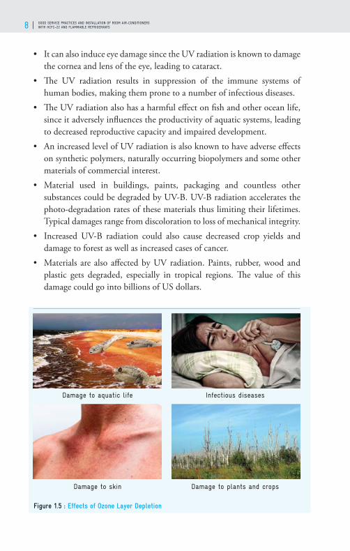
• It can also induce eye damage since the UV radiation is known to damage the cornea and lens of the eye, leading to cataract.
• Th e UV radiation results in suppression of the immune systems of human bodies, making them prone to a number of infectious diseases.
• Th e UV radiation also has a harmful eff ect on fi sh and other ocean life, since it adversely infl uences the productivity of aquatic systems, leading to decreased reproductive capacity and impaired development.
• An increased level of UV radiation is also known to have adverse eff ects on synthetic polymers, naturally occurring biopolymers and some other materials of commercial interest.
• Material used in buildings, paints, packaging and countless other substances could be degraded by UV-B. UV-B radiation accelerates the photo-degradation rates of these materials thus limiting their lifetimes. Typical damages range from discoloration to loss of mechanical integrity.
• Increased UV-B radiation could also cause decreased crop yields and damage to forest as well as increased cases of cancer.
• Materials are also aff ected by UV radiation. Paints, rubber, wood and plastic gets degraded, especially in tropical regions. Th e value of this damage could go into billions of US dollars.
Damage to aquatic life
Damage to skin
Infectious diseases
Damage to plants and crops
Figure 1.5 : Effects of Ozone Layer Depletion

TECHNICIANS HANDBOOK 9
Global Warming
Another important environmental impact of refrigerants relates to the phenomenon of Global Warming. Th e solar radiation interacts with earth’s surface in several ways. Out of the total solar radiation, nearly 20% is refl ected from the earth’s atmosphere, 20% is dispersed into the atmosphere, and 9% is refl ected from earth’s surface or dust. Th e remaining, nearly 51%, penetrates in the atmosphere and reaches the earth’s surface. Most of the solar radiation reaching the earth’s surface are reradiated to the atmosphere. As the reradiated radiation leaves the earth, it once again interacts with the atmosphere. Some of this manages to escape (about 17%), but majority of radiation is returned back to the earth’s surface by the presence of GHGs. Th is refl ected energy warms the surface of the earth, leading to what we call the Greenhouse Eff ect or global warming.
However, some of the green-house gases, such as HCFCs along with other gases like carbon dioxide (CO2), methane (CH4), nitrous oxide (N2O), sulphur hexafl uorides (SF6), halocarbons (HFCs), and perfl uorocarbons (PFCs), essentially emitted through the human activities, cause an increase in the level of greenhouse eff ect leading to high global warming which is responsible for likely mean temperature rise of Earth’s atmosphere.
Figure 1.6 : Global Warming

GOOD SERVICE PRACTICES AND INSTALLATION OF ROOM AIR-CONDITIONERS WITH HCFC–22 AND FLAMMABLE REFRIGERANTS10
Effects of Global Warming
In the last hundred years, the mean global temperature has increased by 0.3 to 0.6°C. Because of this, the sea water thermally expands, and the icecaps melt, leading to rise in sea levels. It destroys coastal towns making people homeless. An increase in global sea level of 4 to 10 inches has been observed over the last 100 years. Th is also aff ects rainfall pattern on the earth, leads to climate changes and thereby alters the bio-diversity.
Due to global warming there is changes in water supply and water quality. Th e habitat the plant and animal species are aff ected. It also has a negative eff ect on human health, as evidenced by increase in cases of Malaria, Dengue and Yellow Fever. According to experts, the world will see a defi nite impact of global warming in the next few decades. Increase in global temperatures, coupled with rapid growth of population, will make society more vulnerable to climate change. It will lead to climatic disorders, droughts, famines, fl oods and longer heat waves spreading to newer areas. Tropical islands and low-lying coastal areas will face the threat of being submerged.
Rising sea level
Habitat damage and species affected
Increased temperature
Changes in water supply
Figure 1.7: Effects of Global Warming
TECHNICIANS HANDBOOK 11
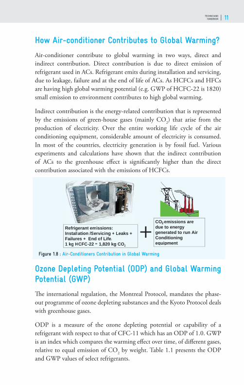
How Air-conditioner Contributes to Global Warming?
Air-conditioner contribute to global warming in two ways, direct and indirect contribution. Direct contribution is due to direct emission of refrigerant used in ACs. Refrigerant emits during installation and servicing, due to leakage, failure and at the end of life of ACs. As HCFCs and HFCs are having high global warming potential (e.g. GWP of HCFC-22 is 1820) small emission to environment contributes to high global warming.
Indirect contribution is the energy-related contribution that is represented by the emissions of green-house gases (mainly CO2) that arise from the production of electricity. Over the entire working life cycle of the air conditioning equipment, considerable amount of electricity is consumed. In most of the countries, electricity generation is by fossil fuel. Various experiments and calculations have shown that the indirect contribution of ACs to the greenhouse eff ect is signifi cantly higher than the direct contribution associated with the emissions of HCFCs.
Ozone Depleting Potential (ODP) and Global Warming Potential (GWP)
Th e international regulation, the Montreal Protocol, mandates the phase-out programme of ozone depleting substances and the Kyoto Protocol deals with greenhouse gases.
ODP is a measure of the ozone depleting potential or capability of a refrigerant with respect to that of CFC-11 which has an ODP of 1.0. GWP is an index which compares the warming eff ect over time, of diff erent gases, relative to equal emission of CO2 by weight. Table 1.1 presents the ODP and GWP values of select refrigerants.
Figure 1.8 : Air-Conditioners Contribution in Global Warming
Refrigerant emissions: Installation /Servrr icing + Leaks +Failures + End of Life.1 kg HCFC-22 = 1,820 kg CO2
+CO2emissions aredue to energy generated to run Air Conditioning equipment

GOOD SERVICE PRACTICES AND INSTALLATION OF ROOM AIR-CONDITIONERS WITH HCFC–22 AND FLAMMABLE REFRIGERANTS12
Table 3.1: ODP and GWP values of select Refrigerants
Refrigerant ODP GWP
CFC-11 1 4750
CFC-12 1 10900
HCFC-22 0.055 1810
Propane (R-290) 0 3
HFC-32 0 675
R-407C 0 1700
R-404A 0 4200
R-410A 0 2100
HFC-134a 0 1430
HFO-1234yf 0 <1
HFO-1233zd(E) 0 <1
HFCs refrigerants have been emerged as the main alternatives to ODSs which have been phased out under the Montreal Protocol. HFCs are not ozone depleting substances but have high global warming potential. So, the parties to the Montreal Protocol decided for an amendment to the Montreal Protocol for phase-down of HFCs at its 28th Meeting of Parties (MOP) held at Kigali, Rwanda. Th is amendment is called as Kigali Amendment to the Montreal Protocol.
Total Equivalent Warming Impact (TEWI)
Global warming or environmental impacts of air-conditioners are due to direct and indirect emissions of greenhouse gases. In addition to the direct impact due to emission of the refrigerant estimated by GWP, air-conditioning system while operating requires energy input, which indirectly aff ects the environment. Th is impact is originated from CO2 emissions from the energy production processes. Th e global warming impacts from air-conditioners can be measured in TEWI (Total Equivalent Warming Impact in kg of CO2).
TEWI combines the eff ects of:• Direct emissions of refrigerants from air-conditioners during its life
time.

TECHNICIANS HANDBOOK 13
• Indirect emission of CO2 from the combustion of fossil fuels for generation of electricity used by the air-conditioner throughout its lifetime.
TEWI provides a measure of the environmental impact of refrigerant and other greenhouse gases from manufacture, operation, service and end-of-life disposal of equipment.
Total Equivalent Warming Impact in kg of CO2
TEWI = mref.GWPref.z + mba.GWPba + t.E.f
Where,mref : Mass of refrigerant in kgGWPref : Global Warming Potential of refrigerant in kg of CO2
z: Number of charges of refrigerant during service lifemba: Mass of blowing agent in kgGWPba : Global Warming Potential of blowing agent in kg of CO2
t: Service life of appliance in yearsE: Annual energy consumption of appliance in kWh/yrf: CO2-factor of energy conversion in kg of CO2/kWhel
Montreal Protocol
Th e Montreal Protocol on Substances that Deplete the Ozone Layer was ratifi ed by India in June 1992. India was classifi ed as a party operating under Paragraph-1, Article-5 of the Montreal Protocol, was thus qualifi ed for technical and fi nancial assistance, including transfer of technology, through the fi nancial mechanism of the Montreal Protocol. India prepared Country Programme incorporating the National Strategy and Action Plan for controlling the use of Ozone Depleting Substances and it was approved in 1993. Since then India has taken proactive measures for ODS phase-out projects including technology transfer investments, technical assistance, training and capacity-building, information dissemination and awareness-raising and regulations. India has established a comprehensive regulatory framework for controlling ODS. As a result, India has consistently been in compliance with the provisions of the Montreal Protocol. Th e Ministry of Environment, Forests and Climate Change (MoEF&CC) has been designated as the nodal ministry for the Montreal Protocol. It has

GOOD SERVICE PRACTICES AND INSTALLATION OF ROOM AIR-CONDITIONERS WITH HCFC–22 AND FLAMMABLE REFRIGERANTS14
established a special directorate, the Ozone Cell, dedicated to managing and coordinating the implementation of the Montreal Protocol in India. India has already phased out production and consumption of CFCs, CTC and halons.
Although HCFCs have much lower ODP than CFCs, all these HCFCs have also been classifi ed as controlled substances under Annex-C, Group-I of the Montreal Protocol. Recognizing the environmental benefi ts of phase-out of production and consumption of HCFCs earlier than the previous control schedule, the XIXth Meeting of the Parties to the Montreal Protocol in September 2007, through its Decision XIX/6, accelerated the phase-out schedule for HCFCs by 10 years.
Th e accelerated HCFC phase-out schedule for Article-5 countries is the freeze in 2013 at the base-line level (an average of 2009 and 2010) for production and consumption respectively and subsequently, 10% reduction of the baseline in 2015, 35% reduction in 2020, 67.5% in 2025 and complete phase-out in 2030 while allowing for servicing an annual average of 2.5% during the period 2030-2040. Th e Phase-out schedule for Article 5 countries is given in fi gure 1.9.
Figure 1.9 : HCFC phase-out schedule for Article 5 countries

TECHNICIANS HANDBOOK 15
HCFC Phase-out in RAC Servicing Sector under Montreal Protocol
Th e HCFC Phase out Management Plans (HPMPs) in India are being implemented under the direct supervision of the Ozone Cell, MoEF&CC, Government of India. RAC servicing sector project under HPMP is being implemented by Government of Germany represented by Deutsche Gesellschaft für Internationale Zusammenarbeit (GIZ) GmbH and United Nations Environment Programme (UNEP) under the guidance of Ozone Cell, MoEF&CC. India has achieved all the compliance target set by the Montreal Protocol for HCFCs. India has established base-line for production and consumption sectors – an average of 2009 and 2010 for production and consumption respectively, achieved the HPMP Stage-I targets, the 2013 freeze and 10% reduction of baseline in 2015 targets. India is now implementing the HPMP Stage-II.
HCFCs are widely used in India in various sectors including Foam, Refrigeration and Air-Conditioning (RAC) manufacturing sector, solvent sector, RAC servicing sector etc. Th e Servicing Sector has a signifi cant consumption of HCFCs, namely, HCFC-22, HCFC-123 due to large and increasing population of RAC equipment in the country. Th e service sector in India has more than 40% of the HCFC consumption. HCFC has a range of applications however it is widely used in room air-conditioners. Sustainable phase-out needs to include the service sector due to the risk of reverse conversions.
HCFCs are being replaced by alternative refrigerants, like HFCs and natural refrigerants. Worldwide, there are well established and energy effi cient technologies available with non-ozone-depleting refrigerants like R-290, HFC-32 and R-410A for the room air-conditioning sector. As R-410A has a high GWP and HFC-32 is having moderate GWP, these refrigerants are not a long-term solution. Due to environmental issues of high GWP refrigerants, natural refrigerants with negligible GWP are gaining more popularity for various applications, including room air-conditioners. Among the hydrocarbons, R-290 (Propane) has similar properties to HCFC-22. R-290 having the characteristics of being fl ammable, the safety issue needs to be addressed, by adequate changes in some electrical components and providing adequate ventilation surrounding the system/equipment.

GOOD SERVICE PRACTICES AND INSTALLATION OF ROOM AIR-CONDITIONERS WITH HCFC–22 AND FLAMMABLE REFRIGERANTS16
Role of Service Technicians to phase-out HCFCs
Phasing-out HCFC in the RAC servicing sector is very important as refrigeration and air conditioning equipment remains in use for up to 10 - 15 years, a signifi cant population of HCFC-based equipment is likely to be still in operation. Th e consumption in the servicing sector will be reduced mainly through training on better servicing practices and leak prevention but service technicians also need to be prepared on the introduction of alternatives like HC-290, HFC-32 etc. Technicians must be trained to appropriately handle the low GWP fl ammable refrigerants.
Th e servicing practices need to be improved not only for reducing the refrigerant requirement in servicing, but also for proper and effi cient functioning of the RAC equipment. During servicing, recovery of refrigerant is not a common practice, especially in developing countries. Th e refrigerant is often vented out and after repair the equipment is recharged with the virgin refrigerant. Th ere is also a practice to top up the RAC equipment with the refrigerant without proper leak detection and repair. Th ere could be signifi cant savings in refrigerant use if proper recovery of refrigerant and good servicing practices are implemented.
Th e refrigerant consumption in the Servicing Sector not only depends on the installed base of RAC equipment, but also on quality of the product and the quality of servicing during product life cycle. Th e quality of servicing depends on knowledge and skill levels of technicians, using appropriate equipment and tools etc. Th e total number of enterprises in the Servicing Sector in India is about 37,000 and the total number of technicians is about 200,000. Th ere could be potentially signifi cant savings in refrigerant use if good service practices are followed, like proper recovery and charging of refrigerants. Th e good service practice is important not only because of environment issue but also to maintain the design energy effi ciency of the air-conditioners. Th e aim of HPMP is to minimize the emissions of ozone depleting substances into the environment and, thus, mitigate the ozone layer depletion.
Kigali Amendment to the Montreal Protocol
Montreal Protocol is successfully phasing out the production and consumption of ODSs. All 197 countries of the world are working together to phase-out ODSs. Although, HFCs are not ozone depleting substances,

TECHNICIANS HANDBOOK 17
but have high global warming potential. Th ese refrigerants emerged as the main alternatives to ODSs which have been phased out under the Montreal Protocol. As ODSs are being phased out, there is a rapid growing of HFCs and it is estimated that by the end of century there will be temperature rise of 0.3 to 0.5oC because of HFCs production and consumption. So, the Parties to the Montreal Protocol on Substances that Deplete the Ozone Layer made agreement at their 28th Meeting of the Parties to the Montreal Protocol on 15 October 2016 in Kigali, Rwanda to phase-down HFCs. It is a dedicated eff ort to reduce GHG emissions through phase-down of HFCs and improve energy effi ciency.
Phase-Down Schedule of HFCs for Article 5 Countries
Th e fi gure 1.11 presents the phase-down schedule of HFCs for Article 5 countries as per the Kigali amendment to the Montreal Protocol. Th ere are four groups, two for non-Article 5 countries and two for Article 5 countries. India opted for the Group 2, recognizing that penetration of cooling is very low in the country but growing rapidly and non-availability of alternatives for all the applications especially the high pressure applications which are needed in the country. Th e baseline for Group 2 Article 5 countries is the average HFCs production and consumption for the years 2024, 2025 and 2026 plus 65% of HCFCs baseline respectively.
Figure 1.10 : Effect of Kigali Amendment on Surface temperature

GOOD SERVICE PRACTICES AND INSTALLATION OF ROOM AIR-CONDITIONERS WITH HCFC–22 AND FLAMMABLE REFRIGERANTS18
Figure 1.11: HFC phase-down schedule for Article 5 countries

TECHNICIANS HANDBOOK 19
AIR-CONDITIONING
02

GOOD SERVICE PRACTICES AND INSTALLATION OF ROOM AIR-CONDITIONERS WITH HCFC–22 AND FLAMMABLE REFRIGERANTS20
Background
To perform good servicing and maintain system effi ciency of air-conditioning, a technician should have knowledge of fundamentals of Air-conditioning including heat loads, vapor compression cycle, diff erent types of air-conditioning systems, parts and components of air-conditioning and their functions, working principle of window and split air-conditioners and electrical components and controls for air-conditioner. Th e basics are discussed in this chapter along with commonly used new technologies such as invertor technology.
Purpose of Air-Conditioning
Air-conditioning is defi ned as “the process of treating air so as to control simultaneously its temperature, humidity, cleanliness and distribution to meet the requirements of the conditioned space”. As the defi nition indicates, the important processes involved in the operation of an air-conditioning system are:• Temperature control• Humidity control• Air fi ltering, cleaning and purifi cation• Air movement and circulation
Figure 2.1: Purpose of Air-conditioning

TECHNICIANS HANDBOOK 21
Th e comfort temperature zone is 22.1°C to 26.7°C (a diff erence of 10-15°C below human body temperature). For comfort, relative humidity varies with the season. In summer, it is about 50-60% and in winter, it is about 45-55%. Th e air movement should be about 1m/s, for a better human comfort, the circulation of air is essential.
Heat Transfer
Heat is a form of energy and it fl ows from a body at a higher temperature to a body at a lower temperature, as shown in fi gure 2.2. For example, hot water in a glass kept in a room, cools down by transferring heat from the hot water to the room.
Air-Conditioning is a process that reduces the temperature of a confi ned space and maintain it at a temperature lower than the ambient temperature. In air-conditioner it is accomplished by transferring heat from the air-conditioned space to refrigerant used in refrigeration cycle and transferring the heat to the ambient (heat sink).
Removal of Heat by the Air-conditioner
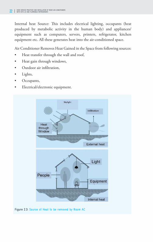
Th e fi gure 2.3 shows the external and internal heat sources in a confi ned space. Th e gained heat to be removed by air-conditioner to maintain temperature and humidity in the confi ned space to provide occupant comfort.
External heat source: Heat fl ows through the exterior walls, roof, windows and infi ltration. Hot or warm air from outside entering the conditioned space through the window/doors gaps is called infi ltration.
Figure 2.2: Heat Transfer
GOOD SERVICE PRACTICES AND INSTALLATION OF ROOM AIR-CONDITIONERS WITH HCFC–22 AND FLAMMABLE REFRIGERANTS22
Internal heat Source: Th is includes electrical lighting, occupants (heat produced by metabolic activity in the human body) and appliances/equipment such as computers, servers, printers, refrigerator, kitchen equipment etc. All these generates heat into the air-conditioned space.
Air Conditioner Removes Heat Gained in the Space from following sources:• Heat transfer through the wall and roof,• Heat gain through windows,• Outdoor air infi ltration,• Lights, • Occupants,• Electrical/electronic equipment.
Figure 2.3: Source of Heat to be removed by Room AC

TECHNICIANS HANDBOOK 23
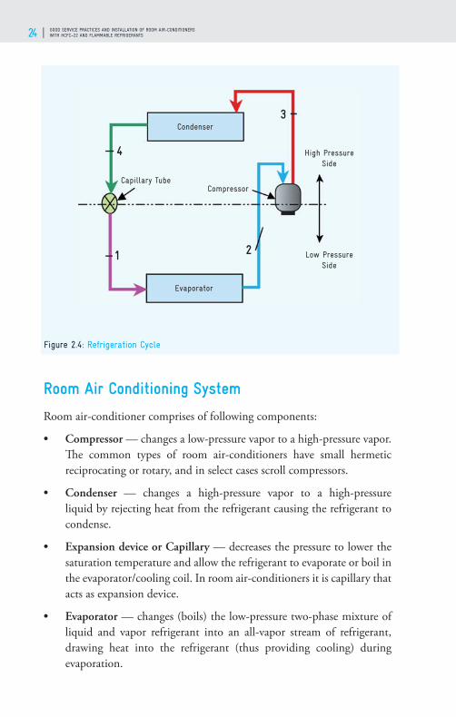
Vapour Compression Cycle
Room Air-conditioner works on the vapour compression refrigeration cycle. A vapour compression refrigeration cycle, as shown in fi gure 2.4, consists of four processes: (1) evaporation, (2) compression, (3) condensation, (4) expansion. Two diff erent pressures exist in air-conditioning cycle - high pressure and low pressure. Evaporator is in low pressure side and condenser in the high pressure side. Th e two pressure areas are due to other two components, one, expansion device or capillary that reduces pressure from condenser pressure to evaporator pressure and controls the refrigerant fl ow. Th e other one is compressor, which increases the refrigerant pressure from evaporator pressure to condenser pressure to enable rejection of heat in the condenser.
Th e liquid refrigerant which is at low pressure in a heat exchanger absorbs heat from air to be cooled, changing its state to vapour. Th e process of a liquid refrigerant evaporating to a vapour state is called ‘evaporation’. Th e component in which evaporation takes place is called an ‘evaporator’. Th e design of an evaporator should be such that the refrigerant should reach a superheated state at its exit. Th e low pressure refrigerant vapour enters the compressor and gets compressed, in this process, the pressure and temperature of the refrigerant increases substantially. Th e refrigerant entering the compressor should be dry and adequately superheated. Th e vapour which emerges from the outlet of the compressor is highly superheated.
After compression, the high pressure superheated refrigerant fl ows through a heat exchanger where heat is rejected to a suitable sink e.g. atmospheric air. Th is heat exchanger is known as a condenser. Th e heat rejection in the fi rst part of the condenser is known as desuperheating. Th e desuperheated refrigerant further rejects heat and it starts condensing in the heat exchanger to a liquid state. In the last part of the condenser, the condensed refrigerant is sub cooled. When the high pressure condensed liquid refrigerant fl ows through the capillary, its pressure decreases. Th e capillary also controls the refrigerant fl ow or quantity into the evaporator. Hence, appropriate capillary diameter and length should be used.
GOOD SERVICE PRACTICES AND INSTALLATION OF ROOM AIR-CONDITIONERS WITH HCFC–22 AND FLAMMABLE REFRIGERANTS24
Room Air Conditioning System
Room air-conditioner comprises of following components:
• Compressor — changes a low-pressure vapor to a high-pressure vapor. Th e common types of room air-conditioners have small hermetic reciprocating or rotary, and in select cases scroll compressors.
• Condenser — changes a high-pressure vapor to a high-pressure liquid by rejecting heat from the refrigerant causing the refrigerant to condense.
• Expansion device or Capillary — decreases the pressure to lower the saturation temperature and allow the refrigerant to evaporate or boil in the evaporator/cooling coil. In room air-conditioners it is capillary that acts as expansion device.
• Evaporator — changes (boils) the low-pressure two-phase mixture of liquid and vapor refrigerant into an all-vapor stream of refrigerant, drawing heat into the refrigerant (thus providing cooling) during evaporation.
Figure 2.4: Refrigeration Cycle
Condenser
Evaporator
1
3
2
4
CompressorCapillary Tube
Low Pressure Side
High Pressure Side

TECHNICIANS HANDBOOK 25
Th e fi gure 2.5 shows the diff erent component in the air-conditioning cycle with state of refrigerant with diff erent colors. Refrigerant between compressor and condenser are in a high-pressure gaseous state. From condenser to expansion device is high pressure liquid state; Expansion device to evaporator is low pressure liquid state and evaporator to compressor is low pressure gaseous state.
Qe: Heat removed from the Space by the refrigerant in Evaporator
P: Power consumed by the Compressor
Qc: Heat removed to ambient by the refrigerant in Condenser, which is equivalent to sum of the Qe and P
Figure 2.5: Air-conditioning components

GOOD SERVICE PRACTICES AND INSTALLATION OF ROOM AIR-CONDITIONERS WITH HCFC–22 AND FLAMMABLE REFRIGERANTS26
Compressor
Compressor is one of the most important components of air-conditioning cycle. It draws in the low temperature and pressure refrigerant gas and then compress it to a high pressure and temperature. Th e high pressure and temperature refrigerant gas is then transferred into the condenser. Th e commonly used compressors in the room air-conditioners are:
Reciprocating – hermetic: A reciprocating compressor is also known as piston compressor. Th e back and forth piston motion in a cylinder synchronized with suction and discharge valves helps to compress the refrigerant vapour from a low pressure and temperature to a high pressure and temperature. Th e operation cycle of reciprocating compressor consists of suction of the refrigerant gas, compression and discharge the compressed gas. In hermetic compressors, the motor and the compressor are enclosed in a housing so that there will be no leakage of refrigerant. Th e housing has refrigerant inlet and outlet and for power input socket connected. Motors reject a part of the power supplied to it due to eddy currents and friction and the compressor also gets heated-up due to friction and also due to temperature rise of the vapor during compression.
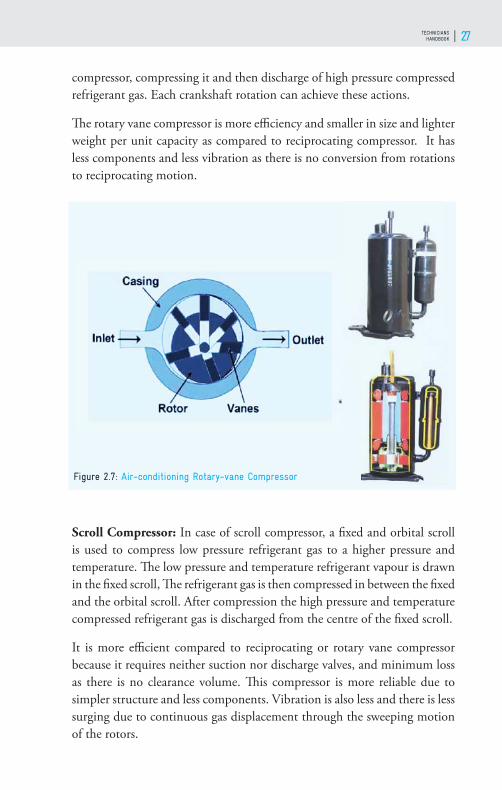
Rotary-vane compressor: Th e function of the vane in the rotary-vane compressor is similar to that of a piston, so, it is also known as a rotary piston compressor. Th e casing which is in stable position acts as a cylinder. Th e suction and discharge sections are made splitting the cylinder and piston rolling inside it with the help of vane. As piston rotates, due to changing of volume of suction and discharge side there will be suction of gas inside the
Figure 2.6: Air-conditioning Reciprocating Compressor
TECHNICIANS HANDBOOK 27
compressor, compressing it and then discharge of high pressure compressed refrigerant gas. Each crankshaft rotation can achieve these actions.
Th e rotary vane compressor is more effi ciency and smaller in size and lighter weight per unit capacity as compared to reciprocating compressor. It has less components and less vibration as there is no conversion from rotations to reciprocating motion.
Scroll Compressor: In case of scroll compressor, a fi xed and orbital scroll is used to compress low pressure refrigerant gas to a higher pressure and temperature. Th e low pressure and temperature refrigerant vapour is drawn in the fi xed scroll, Th e refrigerant gas is then compressed in between the fi xed and the orbital scroll. After compression the high pressure and temperature compressed refrigerant gas is discharged from the centre of the fi xed scroll.
It is more effi cient compared to reciprocating or rotary vane compressor because it requires neither suction nor discharge valves, and minimum loss as there is no clearance volume. Th is compressor is more reliable due to simpler structure and less components. Vibration is also less and there is less surging due to continuous gas displacement through the sweeping motion of the rotors.
Figure 2.7: Air-conditioning Rotary-vane Compressor

GOOD SERVICE PRACTICES AND INSTALLATION OF ROOM AIR-CONDITIONERS WITH HCFC–22 AND FLAMMABLE REFRIGERANTS28
Expansion Devices
An expansion device reduces the pressure & temperature of the refrigerant coming from the condenser as per the requirement of the system. It also regulates the fl ow (metering) of refrigerant as per the load on the evaporator. Expansion device essentially off er resistance to fl ow so that the pressure drops.
Basically, there are two types of expansion devices• Constant restriction type – Capillary tube• Variable-restriction type – Expansion Valve
CONSTANT RESTRICTION TYPE
Capillary tube: Th e capillary tube is a fi xed restriction type expansion device. It is a long and narrow tube connecting the condenser directly to the evaporator. Th e resistance to fl ow permits the capillary to be used as a pressure reducing device to meter the fl ow of refrigerant given to the evaporator.
Figure 2.8: Air-conditioning Scroll Compressor
Figure 2.9: Capillary Tube

TECHNICIANS HANDBOOK 29
Th e Pressure drop through the capillary tube is due to the following:• Friction due to fl uid viscosity, resulting in frictional pressure drop. • Acceleration due to the fl ashing of the liquid refrigerant into vapour
resulting in momentum pressure drop.
Th e cumulative pressure drop must be equal to the diff erence in pressure at the two ends of the tube. For a given state of refrigerant, the pressure drop is directly proportional to the length and inversely proportional to the bore diameter of the tube. Capillary tube is the most commonly used expansion device in room air conditioners. Th e advantage of a capillary tube is its simplicity, low cost and the absence of any moving parts. It should be ensured that the refrigerant must be free from moisture and dirt, otherwise it will choke the capillary and stop the fl ow of refrigerant.
VARIABLE RESTRICTION TYPE:
In this, the extent of opening area of fl ow keeps on changing depending on the type of control.
Two common types are • Automatic Expansion Valve (Pressure Control) • Th ermostatic Expansion Valve
Automatic Expansion Valve: Th is works in response to the pressure changes in the evaporator due to increase in load (pressure increase) or due to decrease in load (pressure decreases). Th is valve maintains a constant pressure throughout the varying load on the evaporator controlling the quantity of refrigerant fl owing into evaporator. Th is consists of a needle valve, a seat, a diaphragm and a spring. Th e opening of the valve is controlled by the two opposing forces, the tension (pressure) in the spring and the pressure in the evaporator acting on diaphragm. Once the spring is adjusted for a desired evaporator pressure and given load, the valve operates, automatically with
Figure 2.10: Automatic Expansion Valve
GOOD SERVICE PRACTICES AND INSTALLATION OF ROOM AIR-CONDITIONERS WITH HCFC–22 AND FLAMMABLE REFRIGERANTS30
changing load conditions in the evaporator.
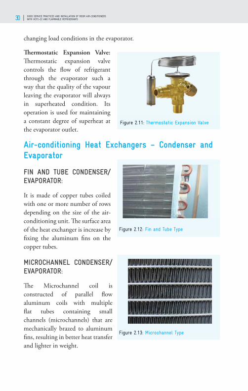
Th ermostatic Expansion Valve: Th ermostatic expansion valve controls the fl ow of refrigerant through the evaporator such a way that the quality of the vapour leaving the evaporator will always in superheated condition. Its operation is used for maintaining a constant degree of superheat at the evaporator outlet.
Air-conditioning Heat Exchangers – Condenser and Evaporator
FIN AND TUBE CONDENSER/EVAPORATOR:
It is made of copper tubes coiled with one or more number of rows depending on the size of the air-conditioning unit. Th e surface area of the heat exchanger is increase by fi xing the aluminum fi ns on the copper tubes.
MICROCHANNEL CONDENSER/EVAPORATOR:
Th e Microchannel coil is constructed of parallel fl ow aluminum coils with multiple fl at tubes containing small channels (microchannels) that are mechanically brazed to aluminum fi ns, resulting in better heat transfer and lighter in weight.
Figure 2.11: Thermostatic Expansion Valve
Figure 2.12: Fin and Tube Type
Figure 2.13: Microchannel Type

TECHNICIANS HANDBOOK 31
Microchannel coils are signifi cantly smaller and effi cient, and use less refrigerant than standard tube and fi n coils.
Rooms Air-conditioners
Room air-conditioners are classifi ed on the basis of their design and features. For example, window room air-conditioners are assembled and pre-charged systems, ready to plug in. Split room air-conditioners have to be assembled on the site. Some models, are designed for heating and cooling, with a reversible cycle they are called as a heat pump.
Working of a Window Air-conditioner (WAC)
Th e working of a window air-conditioner with typical operating temperatures and air fl ow at various locations is shown in fi gure 2.14. Th e colours indicate the temperature of hot or cold air and the refrigerant. Th e components of the window air-conditioner, namely compressor, condenser, capillary, evaporator and fans, are also shown in the fi gure. Th e window AC comprises of both indoor and outdoor components, but these are integrated in a single unit. Th e diff erence between supply and return air temperature is on order of 10-12.5°C.
Figure 2.14: Working of a Window Air-conditioner

GOOD SERVICE PRACTICES AND INSTALLATION OF ROOM AIR-CONDITIONERS WITH HCFC–22 AND FLAMMABLE REFRIGERANTS32
Working of a Split Air-conditioner (SAC)
Th e working of a split air-conditioner along with air temperatures, relative humidity and movements are shown in Figure 2.15,. Th is is very similar to the WAC but the unit is split into two parts, namely, Indoor Unit (IDU) and Outdoor Unit (ODU). Th e colours indicate the temperature of hot or cold air and refrigerant.
Designation of Refrigerants
Refrigerants are designated as given below.
1. Fully saturated halogenated compounds are designated with formula: R XYZ
Figure 2.15: Working of a Split Air-conditioner
HCFC-22 (CHClF2) HFC-32 (CH2F2)
TECHNICIANS HANDBOOK 33
Where, R indicates refrigerant X+1 indicates no. of Carbon atoms (C), Y-1 indicates no. of Hydrogen atoms (H), Z Indicates no. of Fluorine atoms (F)
For example
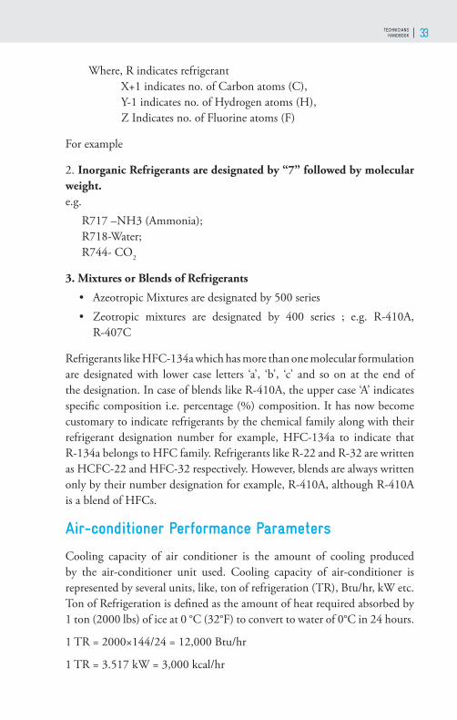
2. Inorganic Refrigerants are designated by “7” followed by molecular weight.e.g.
R717 –NH3 (Ammonia); R718-Water; R744- CO2
3. Mixtures or Blends of Refrigerants • Azeotropic Mixtures are designated by 500 series• Zeotropic mixtures are designated by 400 series ; e.g. R-410A,
R-407C
Refrigerants like HFC-134a which has more than one molecular formulation are designated with lower case letters ‘a’, ‘b’, ‘c’ and so on at the end of the designation. In case of blends like R-410A, the upper case ‘A’ indicates specifi c composition i.e. percentage (%) composition. It has now become customary to indicate refrigerants by the chemical family along with their refrigerant designation number for example, HFC-134a to indicate that R-134a belongs to HFC family. Refrigerants like R-22 and R-32 are written as HCFC-22 and HFC-32 respectively. However, blends are always written only by their number designation for example, R-410A, although R-410A is a blend of HFCs.
Air-conditioner Performance Parameters
Cooling capacity of air conditioner is the amount of cooling produced by the air-conditioner unit used. Cooling capacity of air-conditioner is represented by several units, like, ton of refrigeration (TR), Btu/hr, kW etc. Ton of Refrigeration is defi ned as the amount of heat required absorbed by 1 ton (2000 lbs) of ice at 0 °C (32°F) to convert to water of 0°C in 24 hours.
1 TR = 2000×144/24 = 12,000 Btu/hr
1 TR = 3.517 kW = 3,000 kcal/hr

GOOD SERVICE PRACTICES AND INSTALLATION OF ROOM AIR-CONDITIONERS WITH HCFC–22 AND FLAMMABLE REFRIGERANTS34
Coeffi cient of Performance (COP) or Energy Effi ciency Ratio (EER) is defi ned as the ratio of Refrigeration Eff ect or cooling capacity in watt to the Electrical Power Input watt. Th e performance of any Refrigeration and Air-conditioning system is generally measured by its COP or EER. EER is a dimensionless number. Th e refrigeration eff ect may be expressed in watts (W) or kcal/hr or Btu/hr. Th e power required for running the system is conventionally expressed only in watts. Higher EER means that the power required to run the system is lower for an equivalent cooling capacity. Th erefore, higher EER systems are generally recommended.
Importance of Energy Effi ciency
Th e consumption of electricity will be less if air-conditioners have higher energy effi ciency. Lower energy consumption leads to a reduction in the emissions of CO2 leading to reduction in global warming. Better servicing of air-conditioners also leads to reduction of emission of HCFC-22, resulting in reduction of ozone depletion and global warming. Technicians must remember that neither refrigerant leakage nor excess charging of refrigerant is good and they must improve servicing procedures. In order to protect the environment, it should be ensured that air-conditioners consume less energy and avoid refrigerant leakages. Th e focus should be on achieving the best possible energy effi ciency, with the lowest possible refrigerant emissions. Th is is a key to both environmental and economic sustainability.
Inverter Technology
Fixed speed ACs are lesser effi cient, especially at part load because the system operates with ON-OFF control. Capillary, the constant restriction type is used as expansion devise for fi xed speed ACs. Th e starting power is higher and there is a limitation of effi ciency of AC motors compared to DC motors like compressor motor, condenser motor and evaporator motor.
Figure 2.16: Working principle of Inverter ACs
TECHNICIANS HANDBOOK 35
Th e Inverter technology is the latest evolution of technology, control the speed of the compressor motor, so as to continuously regulate the temperature. Th e DC Inverter units have a variable-frequency drive that comprises an inverter to control the speed of the motor, thus the compressor and the cooling. Th e drive converts the incoming AC current to DC and then through a modulation in an inverter produces current of desired frequency. Th rough microcontroller adjust the speed of the compressor according to the ambient air temperature.
PERFORMANCE OF FIXED AND VARIABLE SPEED ACS:
Air conditioners without inverters consumes high energy during starting the system. It runs to cool a room to a set temperature, then turn OFF once the temperature is reached, then turn back ON again when the temperature rises. Th is repeated ON-OFF process increases the average power consumption. In case of invertor technology the compressor motor speed is regulated by the controller to provide required cooling for the space. Th e power drawn by the compressor motor is reduced accordingly, it enhances the COP of the system.
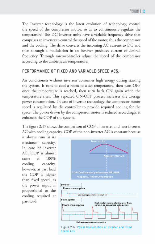
Th e fi gure 2.17 shows the comparison of COP of inverter and non-inverter AC with cooling capacity. COP of the non-inverter AC is constant because it always runs at its maximum capacity. In case of inverter AC, COP is almost same at 100% cooling capacity, however, at part load the COP is higher than fi xed speed, as the power input is proportional to the cooling required at part load.
Figure 2.17: Power Consumption of Inverter and Fixed speed ACs
GOOD SERVICE PRACTICES AND INSTALLATION OF ROOM AIR-CONDITIONERS WITH HCFC–22 AND FLAMMABLE REFRIGERANTS36
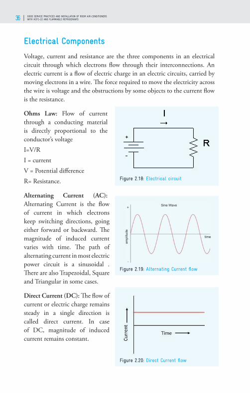
Electrical Components
Voltage, current and resistance are the three components in an electrical circuit through which electrons fl ow through their interconnections. An electric current is a fl ow of electric charge in an electric circuits, carried by moving electrons in a wire. Th e force required to move the electricity across the wire is voltage and the obstructions by some objects to the current fl ow is the resistance.
Ohms Law: Flow of current through a conducting material is directly proportional to the conductor’s voltageI=V/RI = currentV = Potential diff erenceR= Resistance.
Alternating Current (AC): Alternating Current is the fl ow of current in which electrons keep switching directions, going either forward or backward. Th e magnitude of induced current varies with time. Th e path of alternating current in most electric power circuit is a sinusoidal . Th ere are also Trapezoidal, Square and Triangular in some cases.
Direct Current (DC): Th e fl ow of current or electric charge remains steady in a single direction is called direct current. In case of DC, magnitude of induced current remains constant.
Figure 2.18: Electrical circuit
Figure 2.19: Alternating Current fl ow
Figure 2.20: Direct Current fl ow

TECHNICIANS HANDBOOK 37
Electrical Power and Energy: Th e rate of fl ow of electrical energy through an electric circuit is the electrical power. It is a product of voltage and current. Th e unit of electrical power is Watt (W) or kW. Electrical energy consumption is the rate of electrical power consumed at the time duration. It is a product of power of an electrical appliance and time duration of its uses. If power of an appliance is 1 kW, and it is run for 1 hour, then electrical energy consumption will be 1 kWhr
Figure 2.21: LED
Figure 2.22: Transistor
Figure 2.24: Transformer
Figure 2.23: Integrated Circuit (microchips)
LED: LED is made of a p-n junction diode. It releases light when it is oscillated. Energy is released as photons when a suitable voltage is applied to the leads.
Transistor: Transistor is used to amplify or switch electrical power and electronic signal consisting three or more terminals for connecting to an external circuit. It is made of semiconductor materials.
Integrated Circuit (microchips): A semiconductor wafer on which a number of small resistor, capacitors and transistors are fabricated. It works as an oscillator, an amplifi er, a timer, a counter, a microprocessor or a computer memory.
Transformer: Transformer consists of metal core with coils of wire around it. It converts alternating current to the required values by decreasing or increasing the alternating voltages in an electronic or electric circuit. Step down transformers are used for

GOOD SERVICE PRACTICES AND INSTALLATION OF ROOM AIR-CONDITIONERS WITH HCFC–22 AND FLAMMABLE REFRIGERANTS38
air conditioning to step down the voltage from a line voltage to a safer and more effi cient voltage for use in the control of the system.
Resistor: Resistor can be a small carbon device or big wire-wound power resistor, resist or limit the fl ow of current in the circuit.
Capacitor: Capacitor is made of one or more pairs of conductors and an insulator separating them. It is used to store electric charge. Th e following Capacitor are part of Air-Conditioner • Compressor Motor Capacitor:
Th is capacitor gets the motor running in the air conditioning unit.
• Start Capacitor: Th is capacitor provides auxiliary support give, helps the motor a boost to get it started.
• Indoor Blower Motor Capacitor: To start the indoor-blower-motor and keep it running effi ciently.
• Outdoor Fan Motor Capacitor: It starts the outdoor fan and keeps the air fl owing through the coils.
Figure 2.25: Resistor
Figure 2.26: Capacitor

TECHNICIANS HANDBOOK 39
Inductor: Inductor consists of a coil or a wire loop. It is used to store energy in the form of a magnetic fi eld. More the turns in the coil, the more will be the inductance.
Th ermistor: Th ermistor is a kind of resistor which is more sensitive to temperature as compared to other resistors. It is used as an inrush current limiter, temperature sensor, self-regulating heating element and self-resetting overcurrent protector.
Printed Circuit Board (PCB): A PCB acts as a base for the components that are mounted on its surface and are interconnected with wires, conductive tracks and so on.
Relay: Relay is a switch that controls an electrical circuit by opening and closing contacts in another circuit, electromechanically by a magnetic force or electronically. Relays are used in air-conditioner in control circuits to turn system components on and off such as blower motor, condenser fan motor or a compressor.
Switch: Switch is used to make or break connections in an electric circuit. A switch is used to divert the current from one conductor to another.
Figure 2.27: Inductor
Figure 2.28: Thermistor
Figure 2.30: Relay
Figure 2.31: Switch
Figure 2.29: PCB

GOOD SERVICE PRACTICES AND INSTALLATION OF ROOM AIR-CONDITIONERS WITH HCFC–22 AND FLAMMABLE REFRIGERANTS40
Connector: A device which is used to join two circuit together. Th e connector may be a port, a plug, a cable connector etc.
Circuit Breaker: A control and protection device of electrical power system. A switching device which can be operated manually as well as automatically. Its main function is to shield an electric circuit from harm caused by overload or short circuit. It interrupts the current fl ow when protective relays fi nd out a fault. In air-conditioner circuit breakers control all electrical circuit including indoor unit or compressor.
Motor: Motor is used to transform electrical energy into mechanical energy, produces linear or rotary force. Air conditioner motors are crucial components that are required in the operation of the air conditioning.
Capacitor Starts Motor:
Th e capacitor is connected in series with the starter winding, which causes current in starter winding. When motor reaches 75% of the rated speed, the capacitor and the starter winding is disconnected by a switch
Figure 2.32: Connector
Figure 2.33: Circuit Breaker
Figure 2.34: Motor
Figure 2.35: Capacitor Starts Motor

TECHNICIANS HANDBOOK 41
Relay Starts Motor: Relay is connected between the Starter and run winding, which causes current in starter winding. Resistance of motor increases with current, which cuts the start winding then the motor works only on run winding.
Permanent Split Capacitor (PSC) Motor: PSC Motor has a cage ro-tor and the two windings - main and auxiliary windings. It has only one capacitor connected in series with the starting winding. Th e ca-pacitor is permanently connected in the circuit both at the starting and the running conditions.
Capacitor Start Capacitor Run (CSR) Motor: CSR motor has a cage rotor, and its stator- two windings - Main and Auxiliary. Two capacitors - one is used at the time of the starting known as starting capacitor; other one is used for continuous running of the motor and is known as RUN capacitor
Split Phase Induction Motor: Split Phase Induction Motor is also known as a Resistance Start Motor. It has a single cage rotor, and stator - two windings main winding and starting winding. Th e main winding has very low resistance and a high inductive reactance whereas the starting winding has high resistance and low inductive reactance.
Figure 2.36: Relay Starts Motor
Figure 2.37: Permanent Split Capacitor (PSC) Motor
Figure 2.38: Capacitor Start Capacitor Run (CSR) Motor
Figure 2.39: Split Phase Induction Motor

GOOD SERVICE PRACTICES AND INSTALLATION OF ROOM AIR-CONDITIONERS WITH HCFC–22 AND FLAMMABLE REFRIGERANTS42

TECHNICIANS HANDBOOK 43
ALTERNATIVE REFRIGERANTS TO HCFC-22
03
GOOD SERVICE PRACTICES AND INSTALLATION OF ROOM AIR-CONDITIONERS WITH HCFC–22 AND FLAMMABLE REFRIGERANTS44
Background
Refrigerant is a very important for functioning of any refrigeration and Air Conditioning Equipment. Th e refrigerant could be either a single component substance or mixture of two or more single components substances. . It absorb heat from the conditioned space and transfer the heat to atmosphere or any other heat sink. Refrigerant should have the certain properties to run the Air-conditioning system to get the desired cooling and comfort in the space to be air-conditioned and meet the safety and environmental issues. Hydrochlorofl uorocarbons (HCFCs) are one of the family of refrigerants like HCFC-22, HCFC-123 etc., that are widely used as refrigerant for several applications including room ACs. All these HCFC refrigerants are being phased out, as they are having ozone depleting potential.
Need of Alternative Refrigerants to HCFC-22:
HCFC-22 is most suitable and commonly used refrigerant in the room Air-conditioner as it has very good thermodynamic and thermophysical properties and it is widely used refrigerant for room ACs, about 77% of its consumption is in room ACs manufacturing and servicing. But, it is an ozone depleting substance, although the ozone depleting potential is lower than that of CFCs. It is also having high global warming potential. Th e production and consumption of HCFC-22 is being phased out under the Montreal Protocol on substances that deplete the ozone layer. Th erefore, we need alternative refrigerants to HCFC-22 which should have similar or better properties suitable for room air-conditioner, considering the zero-ozone depleting potential and low or negligible global warming potential. Th ere are some alternative refrigerants commercially available and using all over the world. Although these refrigerants are suitable for air-conditioner, they have some diff erent characteristics compared to HCFC-22 and some refrigerants have safety issues. So, as a technician it is very important to know the characteristics of these refrigerants.
Considerations for Selection of Alternate Refriger-ants:
RAC technicians should perform the services such that the environmental eff ect due to room AC system is as much low as possible. Th is can be achieved

TECHNICIANS HANDBOOK 45
when room AC system consumes less energy (high energy effi cient) and refrigerant leakages are minimum/negligible. Whether manufacturers, an engineer/technician, or an owner, the focus of achieving the higher energy effi ciency, with the lower possible emissions is the key to the selected process of alternative refrigerant for maximum climate benefi ts.
Th ere are several factors that should be considered when selecting an alternative refrigerant for air- conditioning systems. Th e alternative refrigerant should have the following desirable characteristics as given in fi gure 3.2:
a. Th e air-conditioner with new refrigerant should have similar or higher effi ciency as compared with HCFC-22.
Figure 3.1: Two important parameters to be considered for Selection of Alternate Refrigerants
Figure 3.2: Desirable characteristics of Refrigerants

GOOD SERVICE PRACTICES AND INSTALLATION OF ROOM AIR-CONDITIONERS WITH HCFC–22 AND FLAMMABLE REFRIGERANTS46
b. It must have zero ODP and minimum/negligible GWP.
c. It must be available in the market and cost must not be too high.
d. It should be preferably non-toxic and non-fl ammable.
e. It must be compatible to all the materials used in air-conditioning system.
f. Th e alternative refrigerant must be having a good lubricant oil miscibility characteristic.
g. Th e stability of a refrigerant is linked to the way it behaves in the presence of other substances, particularly within the refrigerating system. It is important that the refrigerant will not react with, or act as a solvent with any of the materials within the system. Th ese include tubes and other components, compressor motor winding insulation material, compressor oils and associated additives. Th is should also be considered with respect to the small quantities of contaminants such as moisture and air.
Th ere are many refrigerants available, but none have all the characteristics as desired. Except zero ODP, the rest of the parameters have to be traded-off against one another to get the optimum to replace the HCFC-22. So, we have to select the refrigerant having nearest to the desired characteristics.
Safety Classifi cation of Refrigerant
When selecting alternatives to HCFCs, in addition to the conventional desirable properties of refrigerants, safety features must be taken into account. Th e American Society of Heating, Refrigerating and Air-conditioning Engineers (ASHRAE) Standard 34, specifi es the class for safety of refrigerant and gives a designation to the refrigerant. Refrigerants are categorized for fl ammability and toxicity. Th e fl ammability of refrigerant is referred with numbers and toxicity with symbols A or B. Th is classifi cation includes:
Flammability “1” – No fl ammability “2” – Flammable “2L”– Mildly Flammable “3” – Higher Flammability
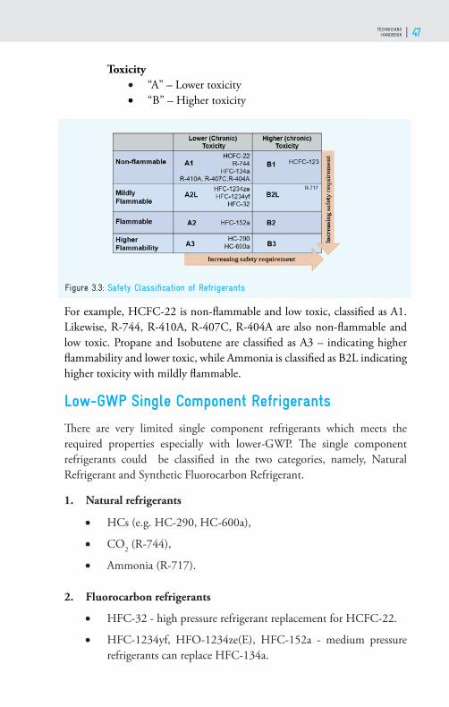
TECHNICIANS HANDBOOK 47
Toxicity “A” – Lower toxicity “B” – Higher toxicity
For example, HCFC-22 is non-fl ammable and low toxic, classifi ed as A1. Likewise, R-744, R-410A, R-407C, R-404A are also non-fl ammable and low toxic. Propane and Isobutene are classifi ed as A3 – indicating higher fl ammability and lower toxic, while Ammonia is classifi ed as B2L indicating higher toxicity with mildly fl ammable.
Low-GWP Single Component Refrigerants
Th ere are very limited single component refrigerants which meets the required properties especially with lower-GWP. Th e single component refrigerants could be classifi ed in the two categories, namely, Natural Refrigerant and Synthetic Fluorocarbon Refrigerant.
1. Natural refrigerants
HCs (e.g. HC-290, HC-600a),
CO2 (R-744),
Ammonia (R-717).
2. Fluorocarbon refrigerants
HFC-32 - high pressure refrigerant replacement for HCFC-22.
HFC-1234yf, HFO-1234ze(E), HFC-152a - medium pressure refrigerants can replace HFC-134a.
Figure 3.3: Safety Classifi cation of Refrigerants

GOOD SERVICE PRACTICES AND INSTALLATION OF ROOM AIR-CONDITIONERS WITH HCFC–22 AND FLAMMABLE REFRIGERANTS48
HFO-1233zd(E), HFO-1336mzz - low pressure refrigerants for the replacement of HCFC-123.
With the continued attention on replacement of refrigerants, coupled with the ever-growing market for Room AC, eff orts are being made to develop to develop and study the alternative refrigerants. A number of refrigerants have been developed but a very few have been commercially used.
Natural refrigerants
Some organic and inorganic compounds which are suitable for use as refrigerant in a refrigeration and air conditioning system applications are termed as natural refrigerants. Natural refrigerants occur in nature’s biological and chemical cycles without human intervention. Th e most common natural refrigerants are hydrocarbons, ammonia and carbon dioxide. Th ey have zero ODP and zero or negligible GWP. Although these refrigerants have safety issues, because of minimal environmental impacts and for being suitable in a sustainable technological development perspective, natural refrigerants could have an important role in the future in diff erent air-conditioning systems. Propane or R-290 is used widely as alternative refrigerant to HCFC-22 for Room Air- Conditioners is discussed below.
Figure 3.4: Low-GWP Single Component Refrigerants
TECHNICIANS HANDBOOK 49
PROPANE OR R-290:
R-290 Room ACs are successfully developed and are being markets. Th e R-290 newly designed Room ACs have better energy effi ciency. It is an excellent alternative to HCFC-22 in the current situation, as it has zero ozone depleting potential and negligible global warming potential. It is a highly fl ammable refrigerant, so safety issues to be addressed adequately. It is commercially available and used by many countries including India.
Th e important characteristics of R-290 are It is a single fl uid hydrocarbon refrigerant, so, easy to handle.
It can be long term solutions due to their zero ODP and negligible GWP.
Boiling point temperature of R-290 is -42.1°C which is slightly lower than HCFC-22.
It is miscible with mineral oil and some other commonly used refriger-ation oils with appropriate viscosities.
No acid formation in combination with water.
Th e system capacities with R-290 are close to with HCFC-22, with hydrocarbons purity class 99.5%.
R-290 is not applicable for retrofi tting for system with HCFC-22, it can only be used in properly designed.
Requires lower refrigerant charge for the same cooling capacity than HCFC-22.
It has higher heat transfer coeffi cient.
Reduction of electrical power consumption due to lower pressure ratio and lower density than HCFC-22.
It is easily available in the market.
Th e main disadvantage of R-290 is that they are fl ammable. R-290 is fl ammable in the range of 2 to 10% volume present in air. Ignition source temperature should be 470°C and above. Th erefore, safety issue needs to

GOOD SERVICE PRACTICES AND INSTALLATION OF ROOM AIR-CONDITIONERS WITH HCFC–22 AND FLAMMABLE REFRIGERANTS50
be addressed, by adequate changes in some electrical components and adequate ventilation surrounding the system/equipment. European Union regulation, EN378 Standard has restricted the refrigerant charge limit of R-290 in air-conditioning systems. Th ere is no restriction for the equipment with R-290 charge quantity 150g or lower. But the equipment with charge quantity above 150g must follow charge limit as per the area of the space or room. R-290 vapour density at 20°C and at atmospheric pressure is higher than that of air, so when leakage it fl ows downward. So, for wall mounted air-conditioners, IDU must be installed at a height of minimum 2.1m. It must be recommended that technicians handling R-290 refrigerant is well trained and always use the PPE.
Fluorocarbon refrigerants
Fluorocarbon is a chemical compound part or all of hydrogen atoms of hydrocarbon including methane and ethane were replaced with fl uorine. Th e fl uorocarbon refrigerants are CFCs HCFCs and HFCs. Th e production and use of CFCs are phased-out globally. HCFCs are being phased-out globally under the Montreal protocol. HFCs are not having ozone depleting potential, but they are having global warming potential. HFC-32, the fl uorocarbon refrigerant used in room AC is discussed below.
HFC-32:
It is a high-pressure refrigerant, higher than that of HCFC-22. It is mildly fl ammable. Th e new system with HFC-32 also have high effi ciency. But, this refrigerant has moderate global warming potential (=675) which is much higher compared to R-290. Th e HFC-32 room ACs have been marketed since 2013 in India. It is also used commercially in many countries.
Figure 3.5: Flammability Characteristics of R-290

TECHNICIANS HANDBOOK 51
Th e important characteristics of HFC-32 are
• HFC-32 is an organic compound of the dihalogenoalkane variety. It is based on methane, except that two of the four hydrogen atoms have been replaced by fl uorine atoms.
• It is also a single component refrigerant, easy to handle.
• It has high global warming potential of 675, although, 37% lower than HCFC-22 refrigerant.
• It is a high-pressure refrigerant, boiling point is -51.7°C.
• Th is refrigerant is miscible with Polyol Easter oils, the most suitable lubricant for system with this refrigerant.
• HFC-32 is mildly fl ammable, fl ammability range of 14 to 31% volume present in air. Its ignition temperature is higher (648°C).
• It has very high refrigerating capacity, about 1.6 times, as compared to HCFC-22, as it has high latent heat of vaporization.
• Refrigerating charge quantity required is lower than the HCFC-22, and so lower refrigerant circulating rate, thus require lower size of compressor.
• Th e heat transfer coeffi cient of HFC-32 is higher than HCFC-22.
• Th e cooling capacity and COP are higher.
• Th is refrigerant is available in the market at lower cost.
Figure 3.6: Flammability Characteristics of HFC-32
GOOD SERVICE PRACTICES AND INSTALLATION OF ROOM AIR-CONDITIONERS WITH HCFC–22 AND FLAMMABLE REFRIGERANTS52
Issues of HFC-32 and R-290 refrigerants
HFC-32 is a high pressure and mildly fl ammable refrigerant. Although R-290 is low pressure, it is highly fl ammable and thus require safer design. Th erefore, to handle R-290 and charge quantity the technician should have knowledge of regulation and standards relating to fl ammable refrigerant. HFC-32 is miscible with POE lubricants which is highly hygroscopic.
On the part of manufacturer safer design is required, but at the same time technicians must follow good service practices considering safety. It must be recommended that technicians handling R-290 and HFC-32 refrigerant is well trained and always use the PPE.
Refrigerants Blends
Th ere are some HFC blends like R-410A and R-407C, available commercially which are being used in refrigeration and air-conditioning. Th ese refrigerants are having no ozone depleting potential but having high global warming potential. So, these refrigerants are not long term solution for alternative to HCFC-22.
R-410A (HFC-32/HFC-125): It is also high-pressure refrigerant like HFC-32. It is widely used refrigerant in Room ACs globally including in India. It is non –fl ammable refrigerant. However it has high global warming potential, so, it is not a long term alternative. Th e phase-down of various HFCs will begin in next 5 to 7 years as per the agreed schedule in the Kigali Amendment to the Montreal Protocol.
R-407C (HFC-32/125/134a): It is also a blend of HFCs. It has a large temperature glide that results in lower cooling capacity as well as energy effi ciency as compared to HCFC-22. Pressure is a little higher than HCFC-22. But, it is also having high global warming potential, so, it is not a long term alternative. Issues with HFC Blends
Azeotropic blends: Th ese types of blends are usually binary mixtures that behave like a pure fl uid. A single temperature defi nes either the evaporation or the condensing pressure.
Zeotropic blends: A zeotropic blend is a mixture of refrigerants whose

TECHNICIANS HANDBOOK 53
diff erent volatilities are seen when observing the performance of a refrigeration cycle. Th ere is change in the molar composition and/or a change in saturation temperature during boiling or condensation, so, it does not behave like a single refrigerant when condensing or evaporating. Two diff erent situations arise, depending upon the type of system.
Th e fi gure 3.7 shows zeotropic mixture of refrigerant components, as it fl ows through a heat exchanger tube. In the case of a pure fl uid, the temperature of the refrigerant remains the same as the liquid vaporizes, or the vapor condenses. However, with a zeotropic blend, as the refrigerant vaporizes, the saturation temperature rises (or as the vapor condenses, the saturation temperature falls). Th e refrigerant is at the bubble temperature when it is just a pure liquid (e.g. when it is just evaporating) and is at the dew temperature when it is just a pure gas (e.g. when it is just condensing).
Temperature glide: Th e characteristic called “temperature glide” occurs when the refrigerant blend has various temperatures as it evaporates or condenses at a single given pressure.
Unsaturated Fluorocarbons (HFOs)
Unsaturated fl uorocarbons refrigerants are composed of hydrogen, fl uorine and carbon atoms, but contain at least one double bond between the carbon atoms. Th ese refrigerants have been developed as these are having zero ODP and very low atmospheric life resulting in negligible GWP (<1). Some of the recently developed refrigerants are described below.
• HFO-1234yf: It is unsaturate d HFC and can replace HFC-134a in same systems since the pressure-temperature characteristics are almost
Figure 3.7: Issues with HFC Blends
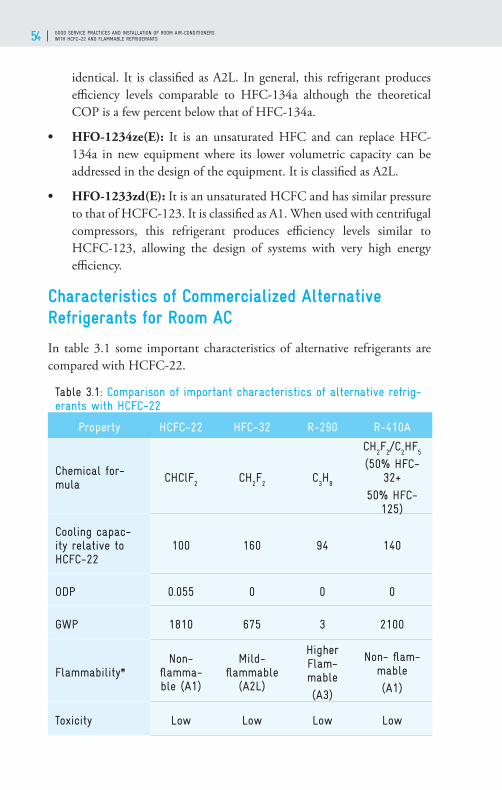
GOOD SERVICE PRACTICES AND INSTALLATION OF ROOM AIR-CONDITIONERS WITH HCFC–22 AND FLAMMABLE REFRIGERANTS54
identical. It is classifi ed as A2L. In general, this refrigerant produces effi ciency levels comparable to HFC-134a although the theoretical COP is a few percent below that of HFC-134a.
• HFO-1234ze(E): It is an unsaturated HFC and can replace HFC-134a in new equipment where its lower volumetric capacity can be addressed in the design of the equipment. It is classifi ed as A2L.
• HFO-1233zd(E): It is an unsaturated HCFC and has similar pressure to that of HCFC-123. It is classifi ed as A1. When used with centrifugal compressors, this refrigerant produces effi ciency levels similar to HCFC-123, allowing the design of systems with very high energy effi ciency.
Characteristics of Commercialized Alternative Refrigerants for Room AC
In table 3.1 some important characteristics of alternative refrigerants are compared with HCFC-22.
Table 3.1: Comparison of important characteristics of alternative refrig-erants with HCFC-22
Property HCFC-22 HFC-32 R-290 R-410A
Chemical for-mula CHClF
2CH
2F
2C
3H
8
CH2F
2/C
2HF
5
(50% HFC-32+
50% HFC-125)
Cooling capac-ity relative to HCFC-22
100 160 94 140
ODP 0.055 0 0 0
GWP 1810 675 3 2100
Flammability*Non-
fl amma-ble (A1)
Mild-fl ammable
(A2L)
Higher Flam-mable (A3)
Non- fl am-mable (A1)
Toxicity Low Low Low Low

TECHNICIANS HANDBOOK 55
In fi gure 3.8 the pressure vs. temperature of HCFC-22, R-290, HFC-32 and R-410A are compared. Th e vapour pressure curves for HCFC-22 and R-290 are very similar. At higher temperature, the pressure of R-290 is slightly lower than HCFC-22. However, for HFC-32 and R-410A, the pressures are higher than HCFC-22.
Refrigeration Oil and Properties
Compressor manufacturers always specify oil type and fi ll each model of compressor accordingly. In hermetic systems, the lubricant is in intimate contact with the electrical motor windings. Th e oil must therefore provide good, material compatibility and have high thermal stability properties. Although the majority of the lubricant remains in the compressor, a small amount will be circulated into the rest of the refrigerant circuit. Th e lubricant must be able to resist both the high temperatures at the compressor discharge valves and the low temperatures at the expansion device. It must be suffi ciently soluble with the refrigerant itself in order for it to be returned back to the compressor, so that over time, it does not become starved of oil, which could lead to mechanical failure.
Th e properties of a good refrigeration lubricant are:
• Low wax content. Separation of wax from the refrigeration oil mixture may plug refrigerant control orifi ces.
• Good thermal stability. It should not form hard carbon deposits and
Figure 3.8: Pressure vs Temperature graph for available alternative refrigerants
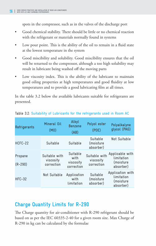
GOOD SERVICE PRACTICES AND INSTALLATION OF ROOM AIR-CONDITIONERS WITH HCFC–22 AND FLAMMABLE REFRIGERANTS56
spots in the compressor, such as in the valves of the discharge port
• Good chemical stability. Th ere should be little or no chemical reaction with the refrigerant or materials normally found in systems
• Low pour point. Th is is the ability of the oil to remain in a fl uid state at the lowest temperature in the system
• Good miscibility and solubility. Good miscibility ensures that the oil will be returned to the compressor, although a too high solubility may result in lubricant being washed off the moving parts
• Low viscosity index. Th is is the ability of the lubricant to maintain good oiling properties at high temperatures and good fl uidity at low temperatures and to provide a good lubricating fi lm at all times.
In the table 3.2 below the available lubricants suitable for refrigerants are presented.
Table 3.2: Suitability of Lubricants for the refrigerants used in Room AC
Refrigerants Mineral Oil
(MO)
Alkyl Benzene
(AB)
Polyol ester
(POE)Polyalkalyne glycol (PAG)
HCFC-22 Suitable SuitableSuitable (moisture absorber)
Not Suitable
Propane
(R-290)
Suitable with viscosity correction
Suitable with
viscosity correction
Suitable with viscosity correction
Applicable with limitation(moisture absorber)
HFC-32Not Suitable Application
with limitation
Suitable(moisture absorber)
Application with limitation(moisture absorber)
Charge Quantity Limits for R-290Th e Charge quantity for air-conditioner with R-290 refrigerant should be based on as per the IEC 60335-2-40 for a given room size. Max Charge of R-290 in kg can be calculated by the formulae

TECHNICIANS HANDBOOK 57
Mmax = 2.5 x (LFL)5/4 x h x (A)1/2
Where,
A = Room area in m2
h = height of the indoor unit installed from ground in m.
LFL =Lower fl ammablility limit of propane = 0.038 kg/m3
Th e fi gure 3.9 shows the charge limit with respect to room fl oor area. Th is fi gure has been developed based on the principle explained above and could be used as to maximum for a given fl oor area and height of mount-ing of indoor unit of Room AC. As shown in the fi gure 3.9, for a 30 m2 fl oor area and indoor unit of Room AC installed at a height of 2.1 m the maximum charge limit is 0.48 kg.
Figure 3.9: Charge Quantity Limits for R-290

GOOD SERVICE PRACTICES AND INSTALLATION OF ROOM AIR-CONDITIONERS WITH HCFC–22 AND FLAMMABLE REFRIGERANTS58

TECHNICIANS HANDBOOK 59
TOOLS AND EQUIPMENT AND MAINTENANCE
04

GOOD SERVICE PRACTICES AND INSTALLATION OF ROOM AIR-CONDITIONERS WITH HCFC–22 AND FLAMMABLE REFRIGERANTS60
Background
Refrigeration and air-conditioning service technicians work mainly with hand tools and equipment. To be successful, the technicians must select quality tools, take good care of them and be skilled in their use. Th e technicians should always use the right hand tools and equipment for the right job and as recommended by the manufacturer of the air-conditioner. Using improper equipment and tools for a specifi c job may be unsafe. For example, using a fl at screwdriver instead of a Phillips screwdriver - the fl at screwdriver tip may slip and result in personal injury. Use of appropriate tools and equipment helps in improving the quality of installation as also repairs and servicing. Th is chapter provide useful information for selection, care and use of RAC tools and equipment.
RAC Tools
SPANNERSCommon types of spanners include open-end spanner, the box spanner and combination spanners. Th ere are also tube-type spanners and adjustable spanners. Th e use of box-end and socket spanner-cum-screwdriver is the best choice when there is adequate space around the nut and bolt. Th e adjustable spanner 150 mm (6”) is a popular type of adjustable wrench spanner necessary for opening / fi xing odd-sized nuts and bolts.
ALLEN KEYSAllen keys are made up of a hexagonal metal bar and can be used to tighten nuts having hexagonal recess on the head. Th e Allen key set comes with various sizes.
Figure 4.1 : Spanners, Line Tester and Allen Keys

TECHNICIANS HANDBOOK 61
LINE TESTERInsulated electric tester (500 V) should be used before start of electric work to test live electric supply in wires and sockets. It also helps to check polarity in the electric socket.
PLIERSDiff erent pliers need to be used as per the requirement. Insulated combination pliers 150 mm (6”) size] help to grip objects and to strip or cut wires. Th is is a handy tool for general use. For safety, it is not advisable to use this on nuts, bolts or fi ttings. To grip a small hardware or to strip or cut wires, insulated nose pliers are recommended. Th is helps to work in a narrow work space. To grip big objects like tubes, nuts or bolts, monkey pliers 100 mm (4”) size can be used.
FILESDepending on the requirement, various types of fi les can be used to remove unwanted burrs while doing operations on tubes or other metal surfaces. A Flat Rough File 200 mm (8”) with a safe handle is recommended when metal is to be removed at a faster rate from a fl at surface. A Round File 150 mm (6”) can be used for cleaning metal surfaces and shaping metal parts in a circular shape.
CRIMPING PLIERSCrimping pliers are necessary for crimping closed end splice & fi xing fastener clips to wire’s end. Th ese can be used to cuts wire and strips wire. Th ese can be also used for crimping solderless connectors onto wires.
PINCH OFF PLIERS /SELF-LOCKING PLIERSAt the end of servicing of window type room air conditioners, tubes need to be pinched and sealed. Pinch off pliers are the ideal tool for this purpose. Th e gap between the jaws of the pinching plier can be adjusted as required.
Figure 4.2 : Pliers and Files
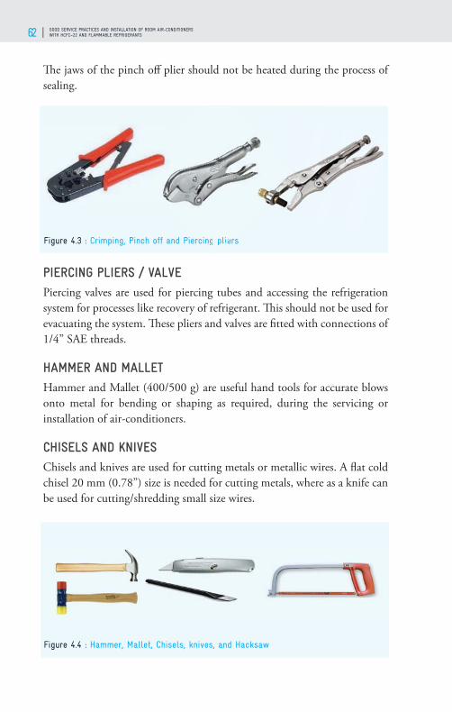
GOOD SERVICE PRACTICES AND INSTALLATION OF ROOM AIR-CONDITIONERS WITH HCFC–22 AND FLAMMABLE REFRIGERANTS62
Th e jaws of the pinch off plier should not be heated during the process of sealing.
PIERCING PLIERS / VALVEPiercing valves are used for piercing tubes and accessing the refrigeration system for processes like recovery of refrigerant. Th is should not be used for evacuating the system. Th ese pliers and valves are fi tted with connections of 1/4” SAE threads.
HAMMER AND MALLET Hammer and Mallet (400/500 g) are useful hand tools for accurate blows onto metal for bending or shaping as required, during the servicing or installation of air-conditioners.
CHISELS AND KNIVES Chisels and knives are used for cutting metals or metallic wires. A fl at cold chisel 20 mm (0.78”) size is needed for cutting metals, where as a knife can be used for cutting/shredding small size wires.
Figure 4.3 : Crimping, Pinch off and Piercing pliers
Figure 4.4 : Hammer, Mallet, Chisels, knives, and Hacksaw
rcing plie

TECHNICIANS HANDBOOK 63
HACKSAWTh e hacksaw is preferred for cutting larger, hard copper tubing. If a saw is used, a wave set blade of 32 teeth per inch is most suitable.
TORQUE WRENCHA torque wrench is a tool used to apply precisely a specifi c torque to a fastener such as a nut or bolt to avoid over /under stressing. A set of torque wrenches (several heads) for up to 200 N.m (2039 kgf.cm) is required specially for tightening fl are connections. An adjustable torque wrench can be used on diff erent sizes of fi ttings suitable for open end spanners.
HAND DRILL MACHINEIt is used to drill the holes on sheet metal for fi tting of screws. With additional attachment, to drill larger holes on walls for refrigeration tubes and drain pipes at the time of installation.
RATCHET WRENCH/SERVICE VALVE WRENCHTh is is also one of the important tools. To open or close the service/cylinder valve which can rotate clock wise or anti clock wise. Instead of this tool if fi eld technicians use plier or adjustable spanner it will damage the valve spindle and it may not be possible to operate the valve after some time. Improper handling of any cylinder valve may cause uncontrollable leakage or worse may be the chances of the accident.
TUBE CUTTER Tube cutters are available in diff erent design and sizes. Tubing cutters make an accurate 90° cut on copper tubing. Th e standard tube cutter is available for tube sizes from 1/8” to 1 1/8”. For confi ned areas mini tube
Figure 4.5 : Torque Wrench, Hand Drill Machine and Ratchet Wrench/Service Valve Wrench

GOOD SERVICE PRACTICES AND INSTALLATION OF ROOM AIR-CONDITIONERS WITH HCFC–22 AND FLAMMABLE REFRIGERANTS64
cutter can be used. During the cutting process, tube cutter is to rotate once around copper tube and then rotate the handle wheel slightly to the level of tightness and then again rotate around the tube. If the handle wheel is tightened too much, the tube will deform and the blade will get damaged.
CAPILLARY TUBE CUTTER It is very important tool for RAC technicians. It can cut the capillary at an angle and with no burs. It consumes very less time, without burs . One can make at an angle of 45 degrees with respect to capillary and apply the capillary cutter. Do not use wire cutters instead of capillary cutter as the wire cutter do not have angle inside the cutter.
DEBURRING TOOLWhen a soft copper tube is cut with a tube cutter, it usually leaves some sharp burrs on the cut ends. Burrs must be removed by reaming in order to keep the tube wall surface smooth and clean. Most tube cutters have a reamer attached to it. Reamer/deburring tool can be used to remove the burr from inside as well as outside of the copper tube. While deburring, keep the tool at the bottom hand and tube on the upper hand, so that all the burs can be collected within the deburring tool otherwise all the burs will enter the copper tube.
FLARING TOOL WITH SWAGING KITTo connect a copper tubing to a fi tting, fl ared type connection is generally used. Flaring tools consist of a tube holding device called fl aring block and a yoke assembly comprised of a feed screw and a smooth surfaced fl are compression cone. Th e tubing is clamped in the fl aring bar, yoke is engaged and feed screw advanced until the cone shape is formed and a moderate resistance is encountered.
Figure 4.6 : Tube cutter, Capillary tube cutter and Deburring tool

TECHNICIANS HANDBOOK 65
In a combination fl aring and swaging tool the block is used for holding the tube and the swaging adaptors attached to the yoke assembly, when tightened with the lever expands the tube to the proper size. Punch type swaging tools are also available for diff erent types of tubes.
TUBE BENDER (LEVER TYPE) Tube bender is an important tool for making neat and accurate bends that does not place any strain on the fi ttings after it is installed. Lever type tube benders do not allow the tubing to kink, fl atten or buckle. Th erefore it is a good practice to use a lever type tube bender during installation and servicing of Air-conditioners. Some technicians use spring bender as they are cheaper.
SCRUBBER CUM WIRE BRUSHUse scrubber to clean outside of copper tubes joints before and after brazing.
TONGSTongs shall be used to lift the objects that are too hot to handle.
MALE AND FEMALE QUICK COUPLERMale & Female couplers are used for joining tubes that eliminate need for fl aring of tubes and save time, avoid leakages that can occur through ordinary valves during servicing. Th ey are suitable for 1/4” copper tubes.
Figure 4.8 : Tube bender (lever type), Scrubber cum wire brush and Tongs
Figure 4.7 : Flaring tool with swaging kit

GOOD SERVICE PRACTICES AND INSTALLATION OF ROOM AIR-CONDITIONERS WITH HCFC–22 AND FLAMMABLE REFRIGERANTS66 GOOD SERVICE PRACTICES AND INSTALLATION OF ROOM AIR-CONDITIONERSWITH HCFC–22 AND FLAMMABLE REFRIGERANTS66
DIGITAL CLAMP METERTh e multifunctional digital clamp meter aids to check the resistance, AC/DC voltage and current. It measures resistance in the range 0-200kΩ, DC voltage up to 1000V, AC voltage up to 750V and AC current 0-300amp. It is also used as a continuity/diode tester with audible beep. Th is can be used for checking earthing in wall socket.
CORE REMOVAL TOOLTh is tool is important for split air-conditioner service. Th is can be used to replace the pin valve on the service port of Split ACs without loss of refrigerant and also for removing the pin valve during recovery of refrigerant from the system and during evacuation of system. To operate this valve fi rst tighten the valve clock wise and hook it on to the core/pin valve, after that attach a charging hose with valve attached to it and rotate anti-clock wise direction. Due to pressure in the system the spindle will be pushed outward, close the valve and do the required procedure.
2-WAY GAUGE MANIFOLDDiff erent types of gauge manifolds are available in the market. Very important to diagnose trouble in air-conditioning systems. Th is is mainly used during evacuation or charging operations. It contains two shut-off valves, three external connections, and two pressure gauges. Th e gauges and the fl exible hoses that connect to the manifold to connect it to the system are colour coded; blue is the low side of the system, red is the high side. Th e left-hand gauge is called a compound or suction pressure gauge. Th e right-hand gauge is called the high pressure or discharge pressure gauge.
Th e right side shut-off valve will control the fl ow through the centre port
Figure 4.9 : Male and female quick coupler, Digital Clamp Meter and Core Removal Toolnd
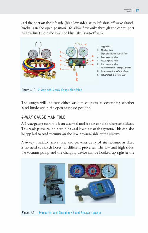
TECHNICIANS HANDBOOK 67TECHNICIANSHANDBOOK 67
and the port on the left side (blue low side), with left shut-off valve (hand-knob) is in the open position. To allow fl ow only through the center port (yellow line) close the low side blue label shut-off valve.
Th e gauges will indicate either vacuum or pressure depending whether hand-knobs are in the open or closed position.
4-WAY GAUGE MANIFOLDA 4-way gauge manifold is an essential tool for air-conditioning technicians. Th is reads pressures on both high and low sides of the system. Th is can also be applied to read vacuum on the low-pressure side of the system.
A 4-way manifold saves time and prevents entry of air/moisture as there is no need to switch hoses for diff erent processes. Th e low and high sides, the vacuum pump and the charging device can be hooked up right at the
Figure 4.10 : 2-way and 4-way Gauge Manifolds
Figure 4.11 : Evacuation and Charging Kit and Pressure gauges

GOOD SERVICE PRACTICES AND INSTALLATION OF ROOM AIR-CONDITIONERS WITH HCFC–22 AND FLAMMABLE REFRIGERANTS68
beginning of the job. Th e manifold is a central control for service. One needs to just operate the appropriate valve.
EVACUATION AND CHARGING KITTh e portable gas charging station has hoses with female quick couplers, weighing balance, manifold, high vacuum pump, vacuum gauge and pressure gauges. Th is helps to evacuate the air-conditioning system to the desired vacuum, charge it with the exact /specifi ed quantity of refrigerant.
PRESSURE GAUGESTh ere are diff erent types of pressure gauges, Bourdon tube type is most commonly used gauge. Th ey are available in diff erent ranges for measuring pressure and vacuum. Vacuum gauge is used to measure pressures lower than the ambient atmospheric pressure (e.g.: −15 psig or −760 mmHg equals total vacuum). A compound gauge is useful to measure pressure at the low and high sides of a running system.
A thermo-couple vacuum gauge is useful for measuring the fi ne vacuum which is diffi cult to measure using a compound gauge. Th is gauge measures the vacuum in microns or Pascals. (1 micron = 0.001mm i.e. 1/1000mm Hg).
ELECTRONIC WEIGHING SCALETh is helps to charge the air-conditioners with the exact amount of refrigerant.
MEASURING TAPEAt the time of installation of window air-conditioners (WAC) and split air-conditioners (SAC), measuring tape is required to measure the room size to calculate heat load and for the proper positioning of the indoor and outdoor units. Th is also helps to cut the tubes of the required size.
Figure 4.12 : Electronic Weighing scale, Measuring Tape and Spirit Level
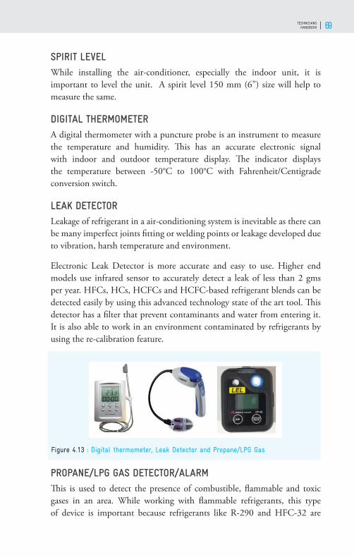
TECHNICIANS HANDBOOK 69
SPIRIT LEVELWhile installing the air-conditioner, especially the indoor unit, it is important to level the unit. A spirit level 150 mm (6”) size will help to measure the same.
DIGITAL THERMOMETER A digital thermometer with a puncture probe is an instrument to measure the temperature and humidity. Th is has an accurate electronic signal with indoor and outdoor temperature display. Th e indicator displays the temperature between -50°C to 100°C with Fahrenheit/Centigrade conversion switch.
LEAK DETECTORLeakage of refrigerant in a air-conditioning system is inevitable as there can be many imperfect joints fi tting or welding points or leakage developed due to vibration, harsh temperature and environment.
Electronic Leak Detector is more accurate and easy to use. Higher end models use infrared sensor to accurately detect a leak of less than 2 gms per year. HFCs, HCs, HCFCs and HCFC-based refrigerant blends can be detected easily by using this advanced technology state of the art tool. Th is detector has a fi lter that prevent contaminants and water from entering it. It is also able to work in an environment contaminated by refrigerants by using the re-calibration feature.
PROPANE/LPG GAS DETECTOR/ALARMTh is is used to detect the presence of combustible, fl ammable and toxic gases in an area. While working with fl ammable refrigerants, this type of device is important because refrigerants like R-290 and HFC-32 are
Figure 4.13 : Digital thermometer, Leak Detector and Propane/LPG Gas

GOOD SERVICE PRACTICES AND INSTALLATION OF ROOM AIR-CONDITIONERS WITH HCFC–22 AND FLAMMABLE REFRIGERANTS70
odorless and any emissions or leakage is dangerous. A gas detector can sound an alarm to operators in the area where the leak is occurring, giving them the opportunity to take necessary precautions.
REFRIGERANT HOSESTh e various types of hoses are refrigerant standard hose, vacuum hose, refrigerant hose with end-mounted ball valve and specially designed HC refrigerant venting hose. Refrigerant standard hose is with 50.8 mm x 6.35 mm (2” x 1/4”) SAE size with female fl are connections of 900 mm (35.43”) length. For minimal refrigerant emission while charging, the refrigerant hose with end-mounted ball valve must be used.
REFRIGERANT CAN ADAPTER WITH FLEXIBLE HOSE Propane is mostly available in cans. It is important to charge the air-conditioner with accurate quantity of refrigerant as specifi ed by the manufacturer. Th erefor it is important to place the refrigerant can properly on an electronic weighing scale and connect it to the gauge manifold with a fl exible capillary type charging line. A refrigerant can adapter with fl exible hose is most suitable for this.
CONTROL VALVEIdeal for using it during refrigerant charging. Eliminates refrigerant or oil, from spraying during connections.
REFRIGERANT RECOVERY MACHINE WITH A RECOVERY CYLINDERSince it is important to reduce HCFCs emission and in line with HCFC phase-out - it is important to recover as much HCFCs as possible. Likewise,
Figure 4.14 : Refrigerant Hoses, Can Adapter with fl exible hose and Control Valve
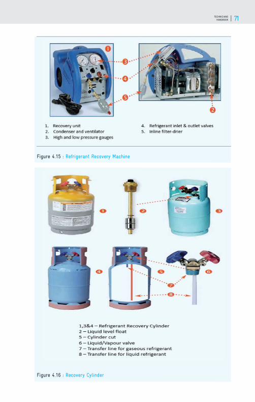
TECHNICIANS HANDBOOK 71
Figure 4.15 : Refrigerant Recovery Machine
Figure 4.16 : Recovery Cylinder

GOOD SERVICE PRACTICES AND INSTALLATION OF ROOM AIR-CONDITIONERS WITH HCFC–22 AND FLAMMABLE REFRIGERANTS72
HFCs should also be recovered as they have high GWP. For such recovery of refrigerants, a recovery machine is required.
It is recommended to use recovery machine with oil-less compressor. Oil less recovery machine does not have the risk of addition of any oil from the compressor to the refrigerant.
Separate recovery cylinders should be used for recovery of diff erent refrigerants. Do not use disposable cylinders for recovery of refrigerant.
BRAZING TOOL KITFor proper brazing using adequate temperature, the minimum requirement is an LPG brazing kit. One example is the swirl jet or spit fi re which can reach higher temperatures than the ordinary LPG torches. It is still better to have oxy-acetylene brazing torch – but economic consideration may not allow this.
BRAZING FILLER METALBrazing fi ller metals can join similar and dissimilar metals at brazing temperature. Brazing fi ller metals melt at temperature range of 538 to 816 C. Some fi ller material used for brazing copper tubing are of two categories, alloys containing 30% to 60% silver, others are copper alloys which contain some phosphorous. Th ese two classes vary in melting, fl owing and fl uxing characteristics. Strong joints can be made with either class of fi ller metal.
HEAT DEFLECTOR
An asbestos-lined heat defl ector should be used to refl ect the heat on to the joints while brazing.
Figure 4.17 : Brazing tool kit and Brazing fi ller metal

TECHNICIANS HANDBOOK 73
REFRIGERANT IDENTIFIERRefrigerant identifi er will provide a fast, easy and accurate means to identify refrigerants and to determine refrigerant purity in storage cylinders. It can be used to determine the concentrations of diff erent refrigerants.
OIL CAN
Oil can is required for oiling the fan motor for better lubrication which is necessary at the time of service.
AIR VELOCITY METER (ANEMOMETER)Anemometer is an apparatus for measuring the speed of air. Th e commonest kind of anemometer is a fan blades fi xed in the circular ring. When placed in an airfl ow direction, the lightweight metal vanes present in the devise rotate due to the fl ow of air through it. Th is rotation speed of the vanes is proportional to the speed of air fl ow through the anemometer. A gearing and clutch mechanism that exists in the device records the number of rotations of the vanes and thus the speed of the air is displayed on the screen.
Figure 4.18 : Refrigerant Identifi er, Oil Can and Heat defl ector
Figure 4.19 : Anemometer, Hand electrical air blower and Sound Level Meter
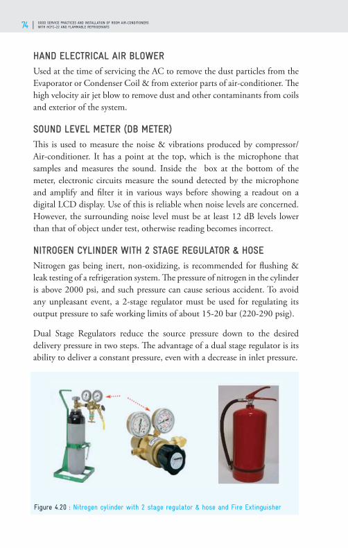
GOOD SERVICE PRACTICES AND INSTALLATION OF ROOM AIR-CONDITIONERS WITH HCFC–22 AND FLAMMABLE REFRIGERANTS74
HAND ELECTRICAL AIR BLOWER Used at the time of servicing the AC to remove the dust particles from the Evaporator or Condenser Coil & from exterior parts of air-conditioner. Th e high velocity air jet blow to remove dust and other contaminants from coils and exterior of the system.
SOUND LEVEL METER (DB METER)Th is is used to measure the noise & vibrations produced by compressor/ Air-conditioner. It has a point at the top, which is the microphone that samples and measures the sound. Inside the box at the bottom of the meter, electronic circuits measure the sound detected by the microphone and amplify and fi lter it in various ways before showing a readout on a digital LCD display. Use of this is reliable when noise levels are concerned. However, the surrounding noise level must be at least 12 dB levels lower than that of object under test, otherwise reading becomes incorrect.
NITROGEN CYLINDER WITH 2 STAGE REGULATOR & HOSENitrogen gas being inert, non-oxidizing, is recommended for fl ushing & leak testing of a refrigeration system. Th e pressure of nitrogen in the cylinder is above 2000 psi, and such pressure can cause serious accident. To avoid any unpleasant event, a 2-stage regulator must be used for regulating its output pressure to safe working limits of about 15-20 bar (220-290 psig).
Dual Stage Regulators reduce the source pressure down to the desired delivery pressure in two steps. Th e advantage of a dual stage regulator is its ability to deliver a constant pressure, even with a decrease in inlet pressure.
Figure 4.20 : Nitrogen cylinder with 2 stage regulator & hose and Fire Extinguisher

TECHNICIANS HANDBOOK 75
FIRE EXTINGUISHERTh is is most important, do not forget to have a powder type fi re extinguisher as only this can be used on any type of fi re (oil, electricity, papers etc.). It should be placed in a safe but rapidly accessible location to make use of it in case of any eventuality. It is better to display the location near the entrance of any workshop or keep it close to brazing kit. Th e label of the extinguisher must be checked for its status.
Quality Maintenance of Select Tools and Equipment
‘Maintenance’ means all actions necessary for retaining an item, tool or equipment in a serviceable condition, or restoring it to a serviceable condition. Th is includes servicing, repair, modifi cation, overhaul, inspection and condition verifi cation. Maintenance increases the availability of tools and equipment when required and keeps the same in working order doing like lubrication, overhauling of equipment and tools and changing oils/lubricants. Good and timely maintenance of tools and equipment ensures assured proper working of the same when required.1. Routine maintenance is a must as electro-mechanical tools/ equipment
are used by RAC technicians.2. Th e basic goal of maintenance is to prevent the failure of tools and
equipment before it actually occurs.3. Maintenance is designed to preserve and enhance reliability of tools
and equipment by replacing worn components before they actually fail.
4. It helps reliability, safety and productivity as also avoids waste, disruption, accidents and inconvenience.
VACUUM PUMPOver time, vacuum pump oil can become oxidized or contaminated by moisture from the system and it reduces the pump’s ability to reach its ultimate vacuum level. Th erefore the oil must be carefully maintained and changed at proper intervals or after the pump is used for about 100 hours. Visually through the sight glass check the oil. If the oil looks milky or rusty, it should be replaced immediately. Always use the type of oil recommended by the manufacturer of the pump. Vacuum pump oil has a low vapor pressure. It is therefore absolutely diff erent from normal hydraulic oil or motor oil.

GOOD SERVICE PRACTICES AND INSTALLATION OF ROOM AIR-CONDITIONERS WITH HCFC–22 AND FLAMMABLE REFRIGERANTS76
Before performing any maintenance always disconnect the vacuum pump from the electrical source. Get the pressures measured with a calibrated vacuum gauge or micron gauge. Maintain a record of maintenance jobs done. Each month check for wear and tear or damage of electrical wires and plugs. If damage or excessive wear and tear is found, replace them. Steps for changing vacuum pump oil:1. Operate the vacuum pump to heat up the vacuum pump oil.2. Turn the vacuum pump switch off and disconnect the electrical cord
plug from the electrical outlet.3. Place the vacuum pump on a level surface.4. Unscrew and remove the oil plug from the bottom of the pump
housing to let the oil drain from the pump completely.5. Refi t the drain plug back into the pump housing.6. Remove the oil fi ll plug at the top of the pump housing.7. Add oil as noted on specifi cation/amount of recommended vacuum
pump oil, to raise the oil level to the full oil level marks of the oil sight glass.
8. Refi t the oil fi ll plug.9. Operate the vacuum pump for a short period of time.10. Check the oil level through the oil sight glass.
MICRON GAUGETh e micron gauge is very crucial in evacuation or system repairs. It must be maintained at its best. Th e sensor has to be regularly checked and kept safe. Always keep the connections clean. A vacuum gauge can sometimes get oil into the vacuum chamber and onto the vacuum sensor and this will aff ect the accuracy of the sensor, clean it only with Isopropyl alcohol. Any other solvents must not be used. Th is being delicate equipment, it must not be tampered on their own but contact the supplier or manufacturer for assistance. Notes to be maintained in the diary or mobile phone about the details of the repair for future reference. Th e record of maintenance has to be maintained.
MANIFOLD GAUGE AND CHARGING HOSESTh e manifold gauge set has to be kept clean for better and safer performance and maintain it regularly. Th e manifolds are generally made of precision
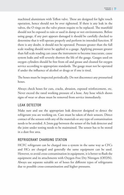
TECHNICIANS HANDBOOK 77
machined aluminium with Tefl on valve. Th ese are designed for light touch operation, hence should not be over tightened. If there is any leak in the valves, the O rings on the valve piston require to be replaced. Th e manifold should not be exposed to rain or used in damp or wet environments. Before using gauge, if any part appears damaged it should be carefully checked to determine that it will operate properly and perform its intended function. If there is any doubt, it should not be operated. Pressure greater than the full scale reading should never be applied to a gauge. Applying pressure greater than full scale reading can cause the instrument to become inaccurate, cause system leaks and will severely shorten the life of the gauge. Gauges used on oxygen cylinders should be free from oil and grease and cleaned for oxygen service according to appropriate standards. Th e gauge must not be operated if under the infl uence of alcohol or drugs or if one is tired.
Th e hoses must be inspected periodically. Do not disconnect any pressurized hoses.
Always check hoses for cuts, cracks, abrasion, exposed reinforcement, etc. Never exceed the rated working pressure of a hose. Any hose which shows signs of wear or abuse must be removed from service immediately.
LEAK DETECTORMake sure and use the appropriate leak detector designed to detect the refrigerant you are working on. Care must be taken of their sensors. Direct contact of the sensors with any of the materials or any type of contamination needs to be avoided. A 2mm gap between the sensor of the leak detector and the joint under testing needs to be maintained. Th e sensor has to be stored in a dust free area.
REFRIGERANT CHARGING STATIONHCFC refrigerant can be charged into a system in the same way as CFCs and HCs are charged and generally the same equipment can be used. However, to avoid cross-contamination in equipment, it is better to fl ush the equipment and its attachments with Oxygen-Free Dry Nitrogen (OFDN). Always use separate suitable set of hoses for diff erent types of refrigerants due to possible cross-contamination and higher pressures.

GOOD SERVICE PRACTICES AND INSTALLATION OF ROOM AIR-CONDITIONERS WITH HCFC–22 AND FLAMMABLE REFRIGERANTS78
RECOVERY UNITAny assembled recovery unit may not be as reliable as commercially manufactured units. Th e compressor can fail and will need replacement if the machine is used on a regular and extensive basis. Th erefore, it is recommended that a spare compressor is kept ready for this purpose. 1. A fi lter dryer must always be used between the recovery machine and
its inlet hose.2. Special care should be taken when recovering from a ‘burnt-out’ air-
conditioner. Two high acid capacity fi lters in series are to be used. After recovery of the refrigerant from the system is complete, it is to be fl ushed with a small amount of OFDN or clean refrigerant and lubricant to purge off any foreign materials left inside.
3. the refrigerant is to be always removed into the external storage cylinder. Liquid refrigerant left in the condenser may expand, causing damage to the components.
4. Ensure that the power supply is disconnected. Before beginning any type of maintenance work.
5. If the unit is to be stored or not used for a long time, it is recommended that it be completely evacuated of any residual refrigerant and purged with OFDN.
6. If any abnormal noise is observed from the recovery machine, it may be an indication of a potential malfunction. Fan blade/ Guard/ mounting may be loose, if left unattended, it can damage the condenser. Check the capacitor mounting, internal hose connections and all electrical connections.
7. In case of under recovery of refrigerant, it may be due to presence of non-condensable gases in the recovery unit or recovery cylinder.
8. Purge all hoses properly and evacuate the recovery cylinder. 9. If it is diffi cult to start the unit, please turn on the purge valve, balance
the internal pressure and make it easier to start.10. Ensure that the inlet and discharge ports are protected and kept clean
by replacing the plastic caps after every use. 11. For best results, keep a fi lter prominently connected to the inlet port
and change it regularly.12. Change hoses periodically as they develop leaks and a build-up of
contaminants over time.

TECHNICIANS HANDBOOK 79
COPPER TUBE PROCESSING & BRAZING
05
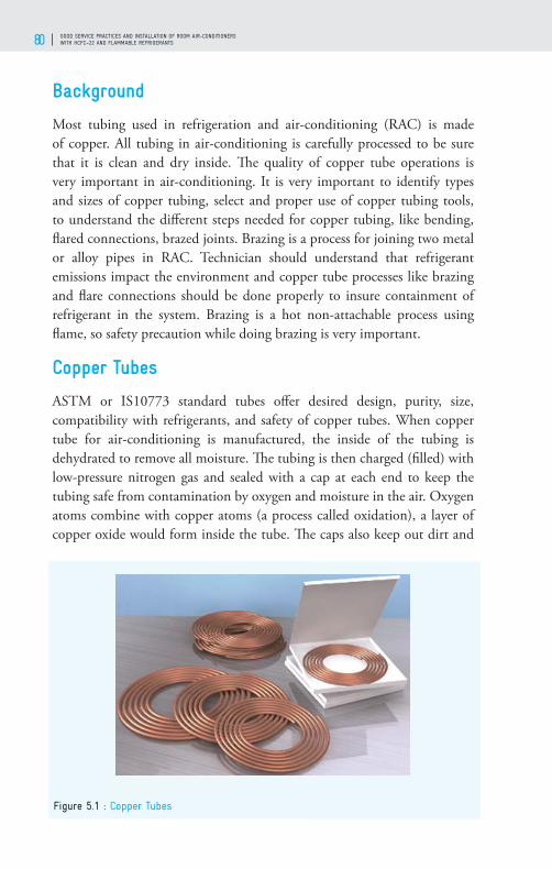
GOOD SERVICE PRACTICES AND INSTALLATION OF ROOM AIR-CONDITIONERS WITH HCFC–22 AND FLAMMABLE REFRIGERANTS80
Background
Most tubing used in refrigeration and air-conditioning (RAC) is made of copper. All tubing in air-conditioning is carefully processed to be sure that it is clean and dry inside. Th e quality of copper tube operations is very important in air-conditioning. It is very important to identify types and sizes of copper tubing, select and proper use of copper tubing tools, to understand the diff erent steps needed for copper tubing, like bending, fl ared connections, brazed joints. Brazing is a process for joining two metal or alloy pipes in RAC. Technician should understand that refrigerant emissions impact the environment and copper tube processes like brazing and fl are connections should be done properly to insure containment of refrigerant in the system. Brazing is a hot non-attachable process using fl ame, so safety precaution while doing brazing is very important.
Copper Tubes
ASTM or IS10773 standard tubes off er desired design, purity, size, compatibility with refrigerants, and safety of copper tubes. When copper tube for air-conditioning is manufactured, the inside of the tubing is dehydrated to remove all moisture. Th e tubing is then charged (fi lled) with low-pressure nitrogen gas and sealed with a cap at each end to keep the tubing safe from contamination by oxygen and moisture in the air. Oxygen atoms combine with copper atoms (a process called oxidation), a layer of copper oxide would form inside the tube. Th e caps also keep out dirt and
Figure 5.1 : Copper Tubes

TECHNICIANS HANDBOOK 81
other foreign matter that could contaminate a refrigeration system. Caps or plugs should be replaced after cutting a length of tubing.
Th e tubes used in air-conditioners are measured based on outside diameter. Air-conditioning and refrigeration tubes are classifi ed based on the thickness of tubes.
Table 5.1: Size of Copper Tubes and their thickness
Outside Diameterinch (mm)
Wall Thicknessinch (mm)
1/4 (6.35) 0.030 (0.762)
3/8 (9.525) 0.032 (0.813)
1/2 (12.7) 0.032 (0.813)
5/8 (15.875) 0.035 (0.889)
3/4 (19.05) 0.035 (0.889)
7/8 (22.225) 0.045 (1.143)
1 1/8 (28.575) 0.050 (1.27)
1 3/8 (34.925) 0.050 (1.27)
Th ree types of copper tubes are available in the market:• K Class: Th ick-walled tubes used for heavy duty applications and where
corrosion might occur.• L Class: Medium thick-walled tubes which are used widely in almost all
applications. (L and K class tubes are suitable for room air-conditioners)• M Class: Th in-walled tubes, it is not used in air-conditioning systems
because it does not meet safety code requirements
Copper Tubing Operations
Copper tube operations involve the following processes.• Straightening and measuring, • Cutting, • Reaming, • Bending, • Cleaning/polishing, • Swaging soft-drawn copper tubing,

GOOD SERVICE PRACTICES AND INSTALLATION OF ROOM AIR-CONDITIONERS WITH HCFC–22 AND FLAMMABLE REFRIGERANTS82
• Flaring soft-drawn copper tubing, and • Brazing.
All these operations need to be done carefully in good service practicing. Using accurate sizes of copper tubes will correctly fi t into each in a telescopic form e.g. 5/8 to ½”,½ to 3/8”, 3/8 to ¼” (15.8 mm to 12.7 mm, 12.7 mm to 9.5 mm,9.5 mm to 6.3 mm).
Tube Straightening and Measuring
A photograph of straightening operation of copper tubing used in air-conditioners is shown in fi gure 5.2. Th is is fi rst step in copper tube processing. Th e straightening must be done from head to tail of tube. Straightening is done by supporting the coil upright with one hand and holding the free end of the tubing stationary on a fl at surface with the other hand (or a foot). Th e coil is then rolled in a straight line to the desired length. Do not straighten out an excessive length of the copper tube as it is diffi cult to recoil the tubing without bends.
Before cutting, marking is important. Th e part marked to be placed on fl at surface safely, free from damage. Th e correct dimensions must be made and incorporated while working on copper tubes.
Figure 5.2 : Tube Straightening and Measuring

TECHNICIANS HANDBOOK 83
Copper Tube Cutting
In air-conditioners servicing, cutting of copper tube must be done precisely. Although, cutting copper tubing is a simple task, it must be performed properly. Care must be exercised not to damage the ends being cut. Th e cutting of the tube should be done using a tube cutter. Copper tubing cutters make an accurate 90°. Th e surface of the cut part should not be rough or slanted. It should be at a right angle to the axis of tube and smooth. Avoid excessive blade pressure; because of more pressure on the cutter, the tube gets cut like pinched and leaves some burr. Avoid twisting the tube and let cutting edge reach the bottom or another side. Select a cutter as per tube size; do not use hacksaw or any other tool to cut soft copper tubing. Th e Hacksaw is used only for cutting larger, hard tubing. Th e cutter blade should be kept sharp. After cutting off the desired length, place the cap or plug on the end of the coil to prevent contamination. A Mini tube cutter can be used in confi ned areas.
Reaming
After cutting, the tube ends will have some sharp burrs and it must be removed. Reaming is a process of removing burrs and scraping the ends to a fl at surface. Tube face and reamer should be facing each other without deviation. To remove the burr, the reamer is positioned at the tube end to be reamed and rotated gently. Both the outer and inner burr is to be removed with the help of a reamer. Care must be taken that copper chips or burrs do not enter inside the tubing. Th e tube must be held upside down or at an angle during the reaming process so the chips will fall on the fl oor. It is important to have a proper dimension of the cut tubing end. Burrs or ridges
Figure 5.3 : Copper Tube Cutting

GOOD SERVICE PRACTICES AND INSTALLATION OF ROOM AIR-CONDITIONERS WITH HCFC–22 AND FLAMMABLE REFRIGERANTS84
on the inside of the tube will cause problems while assembling them. Th e thickness of the tubing at the cut end should match the thickness of rest of the tubing.
Bending
Bending is one of the most important process in copper tubing in the air-conditioning system. Th is operation helps to avoid many joints in the air-conditioner during servicing. While bending care must be taken to ensure that the entire tube surface remains round at the bend. Th e tube should not be fl atten. Proper bending does not allow the tubing to fl atten or kink. Calibrated lever type bending tool should be used. Lever-type tubing benders are easy to operate and are calibrated to allow accurate short radius bends up to 180°. Some benders are designed to fi t only one size of tubing, while others can be used with a range of sizes.
Figure 5.4 : Reaming
Figure 5.5 : Bending
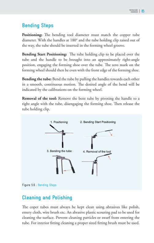
TECHNICIANS HANDBOOK 85
Bending Steps
Positioning: Th e bending tool diameter must match the copper tube diameter. With the handles at 180° and the tube holding clip raised out of the way, the tube should be inserted in the forming wheel groove.
Bending Start Positioning: Th e tube holding clip to be placed over the tube and the handle to be brought into an approximately right-angle position, engaging the forming shoe over the tube. Th e zero mark on the forming wheel should then be even with the front edge of the forming shoe.
Bending the tube: Bend the tube by pulling the handles towards each other in a smooth, continuous motion. Th e desired angle of the bend will be indicated by the calibrations on the forming wheel.
Removal of the tool: Remove the bent tube by pivoting the handle to a right angle with the tube, disengaging the forming shoe. Th en release the tube holding clip.
Cleaning and Polishing
Th e coper tubes must always be kept clean using abrasives like polish, emery cloth, wire brush etc. An abrasive plastic scouring pad to be used for cleaning the surface. Prevent cleaning particles or swarf from entering the tube. For interior fi tting cleaning a proper sized fi tting brush must be used.
Figure 5.6 : Bending Steps

GOOD SERVICE PRACTICES AND INSTALLATION OF ROOM AIR-CONDITIONERS WITH HCFC–22 AND FLAMMABLE REFRIGERANTS86
Swaging
Th e swaging operation helps to join the two tubes of the same diameter. Swaging is the process of enlarging the diameter of one end of a length of soft copper tubing, so the end of another length can be slipped into it. For this operation only, the soft copper tube should be used. Th e swaged copper tube connection to be then brazed. To perform swage, the fl aring block, hammer, and proper size swaging tool are required. Selection of correct size hole to place the tube is very important. Th e position of the tube above the fl aring block should be outer diameter (OD)+3 mm of the tube. Th e length of the overlap of the two copper tubes to be swaged should be equal to OD of the tubing.
Figure 5.8 : Swaging
Figure 5.7 : Cleaning ( L ) Polishing ( R )

TECHNICIANS HANDBOOK 87
Flaring
When connecting tubing to fi ttings, it is a common practice to make fl are connections. To join the copper tube with male threaded fl are fi tting in air-conditioner servicing, fl aring operation must be perfectly performed. Th e end of the soft copper tube is fl ared at 45° angle. Th e fl ared end of tubing rests against the male portion of the fi tting being connected. For fl aring operation, a fl aring block and a fl aring yoke are required. It is a mechanical joint without any gasket in between. Th e soft copper fl are takes the shape of the fi ttings and seals properly. Th erefore, proper attention is very much required while doing the fl aring process. Th e fl ared joint must be done carefully to avoid the emission of refrigerants.
Flaring Steps
After cutting, reaming and cleaning process the following steps to be done.
Assemble the fl aring tool with tube: Place the fl are-nut over the end of the tube with the threads close to the end is fl ared. Th e tube to be inserted
Figure 5.9 : Flaring
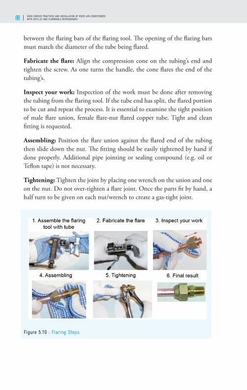
GOOD SERVICE PRACTICES AND INSTALLATION OF ROOM AIR-CONDITIONERS WITH HCFC–22 AND FLAMMABLE REFRIGERANTS88
between the fl aring bars of the fl aring tool. Th e opening of the fl aring bars must match the diameter of the tube being fl ared.
Fabricate the fl are: Align the compression cone on the tubing’s end and tighten the screw. As one turns the handle, the cone fl ares the end of the tubing’s.
Inspect your work: Inspection of the work must be done after removing the tubing from the fl aring tool. If the tube end has split, the fl ared portion to be cut and repeat the process. It is essential to examine the tight position of male fl are union, female fl are-nut fl ared copper tube. Tight and clean fi tting is requested.
Assembling: Position the fl are union against the fl ared end of the tubing then slide down the nut. Th e fi tting should be easily tightened by hand if done properly. Additional pipe jointing or sealing compound (e.g. oil or Tefl on tape) is not necessary.
Tightening: Tighten the joint by placing one wrench on the union and one on the nut. Do not over-tighten a fl are joint. Once the parts fi t by hand, a half turn to be given on each nut/wrench to create a gas-tight joint.
Figure 5.10 : Flaring Steps
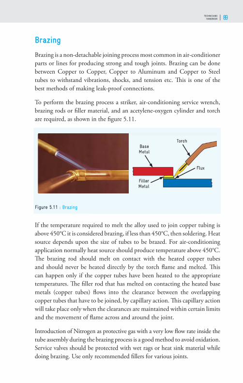
TECHNICIANS HANDBOOK 89
Brazing
Brazing is a non-detachable joining process most common in air-conditioner parts or lines for producing strong and tough joints. Brazing can be done between Copper to Copper, Copper to Aluminum and Copper to Steel tubes to withstand vibrations, shocks, and tension etc. Th is is one of the best methods of making leak-proof connections.
To perform the brazing process a striker, air-conditioning service wrench, brazing rods or fi ller material, and an acetylene-oxygen cylinder and torch are required, as shown in the fi gure 5.11.
If the temperature required to melt the alloy used to join copper tubing is above 450°C it is considered brazing, if less than 450°C, then soldering. Heat source depends upon the size of tubes to be brazed. For air-conditioning application normally heat source should produce temperature above 450°C. Th e brazing rod should melt on contact with the heated copper tubes and should never be heated directly by the torch fl ame and melted. Th is can happen only if the copper tubes have been heated to the appropriate temperatures. Th e fi ller rod that has melted on contacting the heated base metals (copper tubes) fl ows into the clearance between the overlapping copper tubes that have to be joined, by capillary action. Th is capillary action will take place only when the clearances are maintained within certain limits and the movement of fl ame across and around the joint.
Introduction of Nitrogen as protective gas with a very low fl ow rate inside the tube assembly during the brazing process is a good method to avoid oxidation. Service valves should be protected with wet rags or heat sink material while doing brazing. Use only recommended fi llers for various joints.
Figure 5.11 : Brazing

GOOD SERVICE PRACTICES AND INSTALLATION OF ROOM AIR-CONDITIONERS WITH HCFC–22 AND FLAMMABLE REFRIGERANTS90
Safety Precaution while doing Brazing
“Safety First and Everywhere”. During brazing, Personal Protective Equipment (PPE) like goggles, shoes, apron/lab coat and gloves exclusively designed for safety must be worn.
Safety has one more vital issue of smoking. One should never smoke in the work area or laboratory or workplace. Always make a practice to work in the safe working environment and to remind the same install the safety signs apart from First-aid kit and fi re extinguisher at a convenient place. Th is is for self, others and property. While brazing, heat source depends upon the size of tubes to be brazed. It requires to use the tools and equipment with care. If fl ux is needed to be applied do not apply with fi ngers.
Th e torch should never be pointed towards an open fl ame or source of sparks. It is recommended that always a sparker to be used to light the torch, do not use match sticks or cigarette lighter. A fl ashback arrestor for both the acetylene and oxygen regulators should be used. Always keep a fi re extinguisher near the work area.
Brazing Filler Material
Filler material in liquid state distributes between two or more close-fi tting parts to be joined by capillary action. Filler material interacts with a thin layer of the base metal (known as wetting) and when cooled, it forms a sealed/leak-proof joint as a single component.
Th e brazed joint is stronger than the fi ller metals used because of the
Figure 5.12 : Safety Precaution while doing Brazing

TECHNICIANS HANDBOOK 91
geometry of the joint and the metallurgical bonding that occurs. For brazing steel base metal with copper, fi ller material normally used is silver (Ag) 35%. Fluxes made of sodium, potassium, lithium & borax is added as a paste, powder to brazed metal to remove oxides. At least 2% silver alloy to be used as fi ller material for copper to copper joints.
Brazing joint
In the brazing process melted fi ller metal joins the base surface irregular voids such that metallurgical bonding occurs between the fi ller material and
Figure 5.13 : Brazing Filler Material distribution in joints
Figure 5.14 : Brazing Joint

GOOD SERVICE PRACTICES AND INSTALLATION OF ROOM AIR-CONDITIONERS WITH HCFC–22 AND FLAMMABLE REFRIGERANTS92
base material. In a pictorial form a cross-section of the inner and outer tubes being brazed, along with the molten fi ller material is shown in fi gure 5.14. Th e melted fi ller rod as a liquid wet the surface of the copper tubes and penetrates superfi cially into the surface of the copper tubes to form a strong metallurgical bond between the outer surface of one tube and the inner surface of the other tube that overlaps this tube at the joint. Th e boundary-locking layers in the diagram show the metallurgical bond.
Brazing Joint Preparation
Before the start of the brazing process, the tubes are to be prepared. First swage one tube end in the case of the same size tubes. Th e clearance between two tubes should be in the range 0.05 mm to 0.5 mm. Length of joint should be at least equivalent to the diameter of tubes in the case of same size tubes. Clean the surfaces of tubes and ends of tubes with proper materials. While inserting the smaller diameter end into larger diameter end, the tubes must be straight and aligned with each other. Th ere may be brazing of the two dissimilar tubes like ¼” to 3/8”. In such case length of the joint should at least be equivalent to the 1.5 times diameter of the smaller tube. Th e fi rst thing to be done before the commencement of brazing is to ensure that the joints are prepared correctly. Th is involves thorough cleaning of the surfaces to be joined using emery or wire brush to leave a clean and bright surface. Th is will ensure removal of all dirt, greases, oils and other impurities that will otherwise be present on the surfaces and prevent proper wetting of the surfaces. Insert the spigot end into the swaged end/ bigger tube end/ fi tting end. Provide support to the tubes being brazed to retain uniform clearances and prevent slipping, disorientation etc.
Brazing Process
Assembly: Th e pipe and fi tting or expanded pipes are to be kept together and the right joint depth in the system should be maintained.
Torch (fl ame) adjustment: Adjust the torch for a slightly reduced fl ame. Slowly pass nitrogen into the tube work to prevent oxide formation on the inner surface of the tubes. Once the refrigerant is circulating, oxide scale on the inside of the tubes can lead to serious problems. Flow rate should be about 1 to 2 liters per minute. Flow rate sensitively can be felt easily on the back of a moistened hand.

TECHNICIANS HANDBOOK 93
Apply heat: Heat to be applied uniformly to both, tube and fi tting, by moving the torch around to ensure even heating before adding the fi ller material (rod).
Apply fi ller: As the heated area gradually changes color to red (a cherry red but not a bright red), apply fi ller material (rod) by lightly brushing the tip of the stick into the shoulder of the fi tting. Care should be taken not to over-heat the tube.
Remove the heat: Heat to be removed until the molten brazing alloy solidifi es to a tan black color (approx. 10 to 15 seconds).
Types of Flame in Oxy-Acetylene/LPG Brazing
Brazing torch fl ame gets developed when acetylene (C2H2) and oxygen (O2) burn together. Th e fl ame formed are of three types; neutral, reducing and oxidizing. Th e sketches are presented in the fi gure 5.16. In case of neutral fl ame, inner cone gives 2/3rd of heat whereas the outer envelope provides 1/3rd of the energy.
In the mixture of C2H2, and O2, when excess C2H2 is present then combustion of acetylene is incomplete. Th is type of fl ame is good for aluminum alloys and high carbon steels. In burning mixture due to excess
Figure 5.15 : Brazing Process
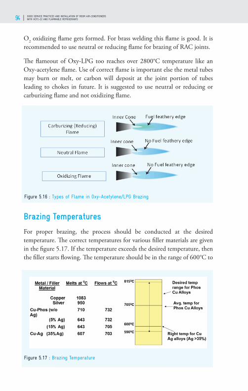
GOOD SERVICE PRACTICES AND INSTALLATION OF ROOM AIR-CONDITIONERS WITH HCFC–22 AND FLAMMABLE REFRIGERANTS94
O2 oxidizing fl ame gets formed. For brass welding this fl ame is good. It is recommended to use neutral or reducing fl ame for brazing of RAC joints.
Th e fl ameout of Oxy-LPG too reaches over 2800°C temperature like an Oxy-acetylene fl ame. Use of correct fl ame is important else the metal tubes may burn or melt, or carbon will deposit at the joint portion of tubes leading to chokes in future. It is suggested to use neutral or reducing or carburizing fl ame and not oxidizing fl ame.
Brazing Temperatures
For proper brazing, the process should be conducted at the desired temperature. Th e correct temperatures for various fi ller materials are given in the fi gure 5.17. If the temperature exceeds the desired temperature, then the fi ller starts fl owing. Th e temperature should be in the range of 600°C to
Figure 5.16 : Types of Flame in Oxy-Acetylene/LPG Brazing
Figure 5.17 : Brazing Temperature
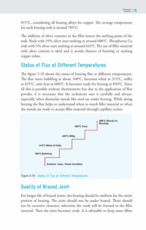
TECHNICIANS HANDBOOK 95
815°C, considering all brazing alloys for copper. Th e average temperature for such brazing rods is around 705°C.
Th e addition of silver contents in the fi ller lowers the melting point of the rods. Rods with 35% silver start melting at around 600°C. Phosphorus Cu rods with 5% silver start melting at around 643°C.Th e use of fi ller material with silver content is ideal and it avoids chances of burning or melting copper tubes.
Status of Flux at Different Temperatures
Th e fi gure 5.18 shows the status of brazing fl ux at diff erent temperatures. Th e fl ux starts bubbling at about 100°C, becomes white at 315°C, milky at 425°C, and clear at 600°C. It becomes ready for brazing at 850°C. Since all this is possible without thermometer but due to the application of fl ux powder, it is necessary that the technician uses it carefully and always, especially when dissimilar metals like steel are under brazing. While doing brazing the fl ux helps to understand when to touch fi ller material or when the metals are ready to accept fi ller material through capillary action.
Quality of Brazed Joint
For longer life of brazed joints, the heating should be uniform for the entire portion of brazing. Th e joint should not be under heated. Th ere should not be excessive clearance otherwise the voids will be formed in the fi ller material. Th en the joint becomes weak. It is advisable to keep some fi llets
Figure 5.18 : Status of Flux at Different Temperatures

GOOD SERVICE PRACTICES AND INSTALLATION OF ROOM AIR-CONDITIONERS WITH HCFC–22 AND FLAMMABLE REFRIGERANTS96
at the joints to compensate for the voids. Always fi ller material should melt on its own and no attempt should be made to drop the fi ller material. Th is makes a good/strong joint.
Advantages of Brazing
Th e advantages of brazing are• Dissimilar metals can be joined.• Good for very thin metal joints.• Metals with diff erent thickness can be joined easily.• Th ermal stresses not produced in the work piece - no warping.• Using this process, carbides tips are brazed on the steel tool holders.

TECHNICIANS HANDBOOK 97
QUALITY INSTALLATION OF SPLIT AIR-CONDITIONERS AND PREVENTIVE MAINTENANCE
06
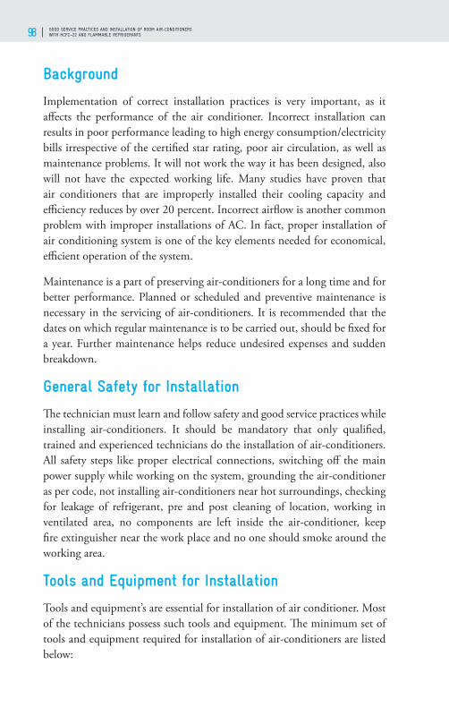
GOOD SERVICE PRACTICES AND INSTALLATION OF ROOM AIR-CONDITIONERS WITH HCFC–22 AND FLAMMABLE REFRIGERANTS98
Background
Implementation of correct installation practices is very important, as it aff ects the performance of the air conditioner. Incorrect installation can results in poor performance leading to high energy consumption/electricity bills irrespective of the certifi ed star rating, poor air circulation, as well as maintenance problems. It will not work the way it has been designed, also will not have the expected working life. Many studies have proven that air conditioners that are improperly installed their cooling capacity and effi ciency reduces by over 20 percent. Incorrect airfl ow is another common problem with improper installations of AC. In fact, proper installation of air conditioning system is one of the key elements needed for economical, effi cient operation of the system.
Maintenance is a part of preserving air-conditioners for a long time and for better performance. Planned or scheduled and preventive maintenance is necessary in the servicing of air-conditioners. It is recommended that the dates on which regular maintenance is to be carried out, should be fi xed for a year. Further maintenance helps reduce undesired expenses and sudden breakdown.
General Safety for Installation
Th e technician must learn and follow safety and good service practices while installing air-conditioners. It should be mandatory that only qualifi ed, trained and experienced technicians do the installation of air-conditioners. All safety steps like proper electrical connections, switching off the main power supply while working on the system, grounding the air-conditioner as per code, not installing air-conditioners near hot surroundings, checking for leakage of refrigerant, pre and post cleaning of location, working in ventilated area, no components are left inside the air-conditioner, keep fi re extinguisher near the work place and no one should smoke around the working area.
Tools and Equipment for Installation
Tools and equipment’s are essential for installation of air conditioner. Most of the technicians possess such tools and equipment. Th e minimum set of tools and equipment required for installation of air-conditioners are listed below:

TECHNICIANS HANDBOOK 99
1. A screwdriver set2. Phillips head screwdriver3. Knife or wire stripper4. Steel tape measure5. Spirit level6. Hacksaw7. Core bits for drilling8. Hammer9. Drilling machine10. Tube cutter11. Tube fl aring tool12. Tube bender13. Torque wrench14. Adjustable wrench15. Reamer (for deburring)16. Refrigeration (thermal) insulation tape17. Insulated staples for connecting electrical wires18. Putty19. Clamps or saddles to protect the refrigerant tubes20. Th ermometer21. Multi-meter or clamp tester.22. Guage manifold23. Th ermometer24. Tong 25. Tester26. Clamp meter27. Brazing cap28. Vacuum pump29. Digital Vacuum meter

GOOD SERVICE PRACTICES AND INSTALLATION OF ROOM AIR-CONDITIONERS WITH HCFC–22 AND FLAMMABLE REFRIGERANTS100
Electrical Power Point
Before starting the installation of the air-conditioner, electrical connections have to be verifi ed for rated current, voltage, and phase connections on the right hand side (RHS) of the socket as shown in fi gure 6.1. Th e technician should ensure that adequate earthing, as per national standards, is provided.
Installation of Split Air-conditioner
In the case of the split air-conditioner, the evaporator is located at a higher position as compared with the window air-conditioner. Cool air has higher density than hot air. Th e air which comes in contact with the evaporator coil or cooling coil gets cooled and cold air is supplied through the supply grill to the space (room) with a certain throw and velocity. Th e cold air being of higher density, fl ows downward towards the fl oor. Th e warm air moves
Figure 6.1 : Electrical Power Point
Figure 6.2 : Proper Location for SAC

TECHNICIANS HANDBOOK 101
up as it is lighter than the rest of the air in the room. Th is phenomenon has been shown in fi gure 6.2.
Location for Indoor Unit (IDU)
Th e IDU must be mounted on a strong wall, away from direct heat and breeze. Th ere should not be any obstruction to the circulation of air. Th ere should be adequate space, more than 150 mm (6”), around the IDU. Th e distance between the ceiling and the IDU should be more than 50 mm (2”) in the case of front suction or grille design and more than 150 mm (6”) in the case of top suction or fl at front panel design. For the drain, the tube should slope towards the outside of the wall. Th e location should be away from fl ammable materials and the tubing should have minimum bends and elbows. A hole should be drilled in the wall for the drain tube, refrigerant tubes and electrical cable, etc. Th e hole size should be decided to accommodate all the elements mentioned.
Installation of IDU
Following are the steps for installation of the IDU:1. Align the installation plate on the wall horizontally, and mark locations
for fasteners. Using the spirit level, mark the vertical center line.2. Drill 6 mm (0.23”) holes at the marked points, insert sheaths/plugs
and fi t the installation plate with eight screws.3. Open the cover of the hole of the plastic tube as per suitable direction
for drainage.4. Drill a hole of 70 & 100 mm (2.7” & 4”) diameter for 1.0 TR and 2.0
TR units respectively for tubing and wires.5. Th e holes must be slightly sloping, 4 - 6 mm towards the outdoor side.
Figure 6.3 : Proper Location for Indoor Unit (IDU)

GOOD SERVICE PRACTICES AND INSTALLATION OF ROOM AIR-CONDITIONERS WITH HCFC–22 AND FLAMMABLE REFRIGERANTS102
6. Drill the tubing hole on the right or left side of the installation plate as per the drain line.
7. Use a special conduit for allowing the tubes to smoothly slide out.
Location for Outdoor Unit (ODU)
For quality installation of ODU, a strong foundation is required, away from direct heat. Th ere should be no obstruction to air circulation. Th e space around the ODU must be more than 150-250 mm (6”–9.8”) in the rear and more than 1500 mm (59”) in front of the unit. It should be placed away from any fl ammable materials. If there is a shade above the ODU, it will improve its performance. Avoid locating the ODU where it would be exposed to the salty atmosphere. Th e tubing should have minimum bends and elbows.
Figure 6.4 : Installation of Indoor Unit (IDU)
Figure 6.5 : Proper Location for ODU

TECHNICIANS HANDBOOK 103
Installation of ODU
Th e following instructions have to be followed while installing the ODU:1. Ensure that the base for installation of the ODU is rigid.2. In case the site is located where the breeze is strong, or if it is at a high
altitude, install the ODU lengthwise along the wall, using a shield to protect the working of the fan. Select a site for ODU in such a way that its access is easy for installation and future servicing.
3. If the drainage is bad, or if water is likely to accumulate near the outdoor unit, place the ODU on a concrete block or raised platform, if possible.
4. If the outdoor unit vibrates too much, adjust the angle of the installation legs. In case the unit is likely to tilt or fall, bolt it with 8 mm (0.31”) diameter anchor bolts.
Installation of Split Air Conditioner Tubes
Following are the steps for the installation of refrigerant tubes. Th e technician should follow the procedure for installation of tubes without any deviation.1. Make a hole of 70 -100 mm (2.75” – 4”) diameter in the wall (L or R)
for taking out tubes, drain tube and wires.2. Measure the distance between the IDU and ODU, including all bends.3. Cut the tubes a little longer than the measured distance.4. Remove burrs from the cut edges of the tubes.
Figure 6.6 : Installation of ODU

GOOD SERVICE PRACTICES AND INSTALLATION OF ROOM AIR-CONDITIONERS WITH HCFC–22 AND FLAMMABLE REFRIGERANTS104
5. Remove the fl are nut from the tube end.6. Flare the tube ends after inserting fl aring nuts.7. Tape the fl aring portion to protect it from dust or damage.8. Align the centers of both fl ares at both IDU and ODU. Tighten the
fl are nuts.9. Insulate all tubes for better performance.10. Connect the drain hose and extend it with a rigid tube if required.11. Insulate the drain hose laid indoors. Th e drain hose should be inclined
downward.12. Remove fi lters and pour water into the drain pan to confi rm the
smooth fl ow of water.
Connecting the Tubes
For connecting IDU & ODU with compressor, copper tubing is necessary. When height between IDU and ODU is about 3 m then the length of the tube should be 5 m and when height is 7 m then the length should be 10 m. Connect the piping to the Indoor Unit. Align the centers of both fl ares (IDU & piping) and tighten the fl are nuts connecting the piping to the outdoor unit. Apply torque that is just right for fl are nuts, over tightening shears the tubes, ultimately resulting into the leak.
Insulate all tubing’s for better performance. Th e fi gure 6.7 shows the various color codes for tubes carrying liquid and gaseous refrigerant, drain, and 3 core electrical wires. It is just that the drain pipe should be inclined so that condensate drains. In the case of the drain pipe placed like siphon, the condensate will not fl ow.
Figure 6.7 : Copper Tube Connections

TECHNICIANS HANDBOOK 105
For air-conditioners with fl ammable refrigerants it is advisable to avoid fl are connections inside the room. If refrigerant tubings are to be connected indoors, cut the fl are connections, swage the tube ends and join the tubes by brazing.
Tightening Torque Required for Different Size Flare Nuts
Th e torque required for tightening diff erent tube sizes varies according to the diameter of the tube. Apply torque that is just right for fl are nuts, over tightening shears the tubes, ultimately resulting into the leak. If a fl are joint leaks even after tightening to the required torque, the reason for leakage may be due to bad fl are, burrs on tube and wrong size fl are. Th en cut the tube and make the new fl are.
Table 6.1: Torque required to tighten fl are joints
Flare sizeMin. Wall
thickness (mm)Torque (Nm)
Metric (mm) Imperial Seriesmm inch
6 0.8 14 to 18
6.35 1/4 0.8 14 to 18
7.94 5/16 0.8 33 to 42
8 0.8 33 to 42
9.52 3/8 0.8 33 to 42
10 0.8 33 to 42
12 0.8 50 to 62
12.7 ½ 0.8 50 to 62
15 0.8 63 to 77
15.88 5/8 0.95 63 to 77
18 1.0 90 to 110
19.06 4/4 1.0 90 to 110

GOOD SERVICE PRACTICES AND INSTALLATION OF ROOM AIR-CONDITIONERS WITH HCFC–22 AND FLAMMABLE REFRIGERANTS106
Leak testing
For reliability and environment protection, the system must be pressure and leak tested. Do not purge the system with refrigerant or use it for leak testing. Th is is due to fl ammability and GWP concerns. Th e system should be checked for leakage using OFDN.
Nitrogen required for fl ushing and leak testing in refrigeration and air conditioning applications should be 99.995% pure free from oxygen, air dust etc. and dew point at least -40°C. If nitrogen of these specifi cations is not available, connect 25g drier-fi lter to the nitrogen cylinder hose prior to the inlet valve of hose to be connected to air-conditioner system. Th e test pressure of OFDN should be higher than operating pressure. Procedure for leak testing is similar for HCs & HFCs. Keep the system under pressure for 15 minutes and observe for any drop in pressure. If there is any drop in pressure identify the leak and rectify it. Use of soap solution for leak testing is permitted when the system is under positive pressure. Apply soap solution on each joint with the help of a brush and look for leakage, if any.
Evacuation
Th e system should be free from air, moisture, and non-condensable gases to ensure proper and effi cient operation of the air conditioner. Th erefore, it is important to evacuate the IDU during installation of the air-conditioner. For deep vacuum, a suitable 2-stage rotary vane vacuum pump should be deployed (100-120 lpm. & blank-off 20 microns). Use micron gauge
Figure 6.8 : Evacuation

TECHNICIANS HANDBOOK 107
to measure evacuation pressure. Th e evacuation must reach 500 or lower microns level. A Bourdon type vacuum gauge cannot read vacuum in microns – hence actual vacuum reached cannot be known.
However, in the absence of a micron vacuum gauge, the vacuum pump should be run for at least about 15 minutes after the Bourdon type vacuum gauge reading shows -30” / -760 mm / 0 millibar (at sea level).
Additional Refrigerant Quantity for SAC
If the distance between IDU and ODU are longer than OEM suggested one, the quantity of refrigerant specifi ed by the manufacturer may not be suffi cient and additional refrigerant will have to be charged.
Usually, the standard length of tubing is 4 meters only. Additional gas charge quantity varies with the length and diameter of the refrigerant tubing.
For air-conditioners with fl ammable refrigerants the selection of air-conditioner is made based on the room size and refrigerant charge quantity. Th erefore, it is necessary to consult the manufacturer before extending the refrigerant tubes or charging additional refrigerant.
ADDITIONAL CHARGE FOR HCFC-22 UNIT IS CALCULATED AS:
For 6.35 mm (1/4”) liquid tube and 12.7 mm (1/2”) gas tube with a total measured length of 15 m (49.2 ft), the additional charge will be approximately 256 g of HCFC-22. Th e technician must use the table given here below for calculation of additional charge in case of HCFC-22 units. Alternatively, OEMs need to be contacted or their service manuals must be referred to for this purpose.
Table 6.2: Additional Refrigerant Charge
Gas Tube dia g/m Liquid Tube dia g/m
12.7 mm (1/2”) 1.87 6.35 mm (1/4”) 21.38
15.87 mm (5/8”) 3.71 7.94 mm (5/16”) 37.16
19.05 mm (3/4”) 5.58 9.52 mm (3/8”) 57.66
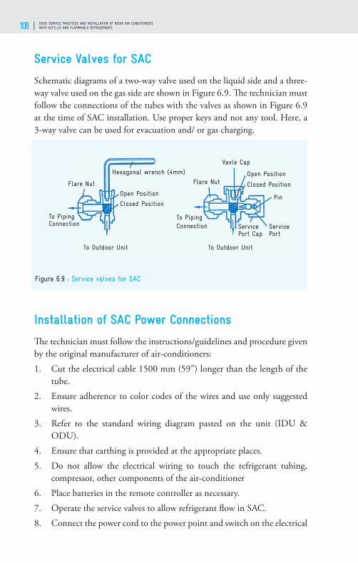
GOOD SERVICE PRACTICES AND INSTALLATION OF ROOM AIR-CONDITIONERS WITH HCFC–22 AND FLAMMABLE REFRIGERANTS108
Service Valves for SAC
Schematic diagrams of a two-way valve used on the liquid side and a three-way valve used on the gas side are shown in Figure 6.9. Th e technician must follow the connections of the tubes with the valves as shown in Figure 6.9 at the time of SAC installation. Use proper keys and not any tool. Here, a 3-way valve can be used for evacuation and/ or gas charging.
Installation of SAC Power Connections
Th e technician must follow the instructions/guidelines and procedure given by the original manufacturer of air-conditioners:1. Cut the electrical cable 1500 mm (59”) longer than the length of the
tube.2. Ensure adherence to color codes of the wires and use only suggested
wires.3. Refer to the standard wiring diagram pasted on the unit (IDU &
ODU).4. Ensure that earthing is provided at the appropriate places.5. Do not allow the electrical wiring to touch the refrigerant tubing,
compressor, other components of the air-conditioner6. Place batteries in the remote controller as necessary.7. Operate the service valves to allow refrigerant fl ow in SAC.8. Connect the power cord to the power point and switch on the electrical
Figure 6.9 : Service valves for SAC

TECHNICIANS HANDBOOK 109
power supply to the unit.9. Set the control panel as desired and start the air-conditioner.10. Permit the air-conditioner to run for about 20-25 minutes.11. Observe suction pressure and supply and return air temperature. 12. Reinstall the locknuts on the service valves. Do the fi nal leak testing.
Ensure that there are no leaks.13. Give a demonstration for eff ective use.14. Fill up the warranty documents of the air-conditioner.15. Record all observations as a report and fi ll up the checklist on
completing the installation.16. Before leaving the site, collect all the belongings.17. Take your leave politely of the customer.
Post-Installation Check-up
Th e following is a questionnaire for evaluation of work done:1. Is the air-conditioner installed securely?2. Is there enough space provided around the IDU and ODU for better
performance?3. Is anything obstructing the circulation of air?4. Are all gaps around the unit fi lled with thermal insulation?5. Is care taken to avoid any potential complaints from neighbors about
vibration and dripping of water?6. Are electric wires used as per the requirements?7. Is the earthing wire connected properly to the units?8. Are line voltage and supply of current as specifi ed?9. Ensure no leakage of refrigerant.10. Check operations of the electronic and electrical control panel.11. Has the temperature of supply and return air been noted? (Diff erence
to be 10-12°C)12. Does the drain fl ow out smoothly?13. Has the customer been educated with regard to benefi ts, fi lter cleaning,
front grille panel, regular maintenance?
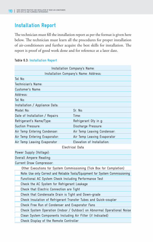
GOOD SERVICE PRACTICES AND INSTALLATION OF ROOM AIR-CONDITIONERS WITH HCFC–22 AND FLAMMABLE REFRIGERANTS110
Installation Report
Th e technician must fi ll the installation report as per the format is given here below. Th e technician must learn all the procedures for proper installation of air-conditioners and further acquire the best skills for installation. Th e report is proof of good work done and for reference at a later date.
Table 6.3: Installation Report
Installation Company’s Name:
Installation Company’s Name: Address:
Tel No:
Technician’s Name:
Customer’s Name:
Address:
Tel No:
Installation / Appliance Data:
Model No: Sr. No:
Date of Installation / Repairs Time:
Refrigerant’s Name/Type: Refrigerant Qty in g:
Suction Pressure: Discharge Pressure:
Air Temp Entering Condenser: Air Temp Leaving Condenser:
Air Temp Entering Evaporator: Air Temp Leaving Evaporator
Air Temp Leaving Evaporator Elevation of Installation:
Electrical Data
Power Supply (Voltage):
Overall Ampere Reading:
Current Draw Compressor:
Other Executions for System Commissioning (Tick Box for Completion)
Note: Use only Correct and Reliable Tools/Equipment for System Commissioning
Functional AC System Check Including Performance Test
Check the AC System for Refrigerant Leakage
Check that Electric Connection are Tight
Check that Condensate Drain is Tight and Down-grade
Check Insulation of Refrigerant Transfer Tubes and Quick-coupler
Check Free Run of Condenser and Evaporator Fans
Check System Operation (Indoor / Outdoor) on Abnormal Operational Noise
Clean System Components Including Air Filter (if Indicated)
Check Display of the Remote Controller

TECHNICIANS HANDBOOK 111
Installation Company’s Name:
Installation Company’s Name: Address:
Execute Briefi ng of the AC System User
Company Signature and Date
Customer Signature and Date:
Preventive Maintenance of Room Air-conditioners
Regular maintenance of room air-conditioners will improve their life, performance, reliability and safety. Preventive maintenance is also important to maintain the original energy effi ciency of the system and for the environmental perspective, so that there would be no leakage of refrigerant to the environment. To prevent chance of sudden failure of the system, it is good to have periodic inspection, cleaning and replacing the defective parts. Also, due to poor functioning of some parts of the system, it is good to replace those parts before it will actually fail to work, otherwise it will lead to higher energy consumption or leakage of refrigerants. Manufacturers recommend the schedule for the preventive maintenance; the technicians are advised to follow the preventive maintenance as the schedule specifi ed. Maintenance is necessary to be carried out by both customer and technical professionals viz. service technicians. Given below are the tasks to be performed by the customer and the technicians.
MAINTENANCE BY CUSTOMER• Change and/or clean the primary fi lter every two months. If the unit
is equipped with a plasma indoor air quality fi lter, clean it when the reminder light illuminates.
• Vacuum dust from the indoor evaporator coil and wipe away built-up dirt. Leave heavier, stubborn dirt deposits or mould accumulation for cleaning by a professional technician.
• Clean the condensate drain pan, drain and verify that the drain is open. If there’s evidence of mould or other bacterial growth, let a technician handle it.
• Cut weeds or other encroaching vegetation from around the outdoor condenser to allow two feet of free space on all sides for airfl ow.

GOOD SERVICE PRACTICES AND INSTALLATION OF ROOM AIR-CONDITIONERS WITH HCFC–22 AND FLAMMABLE REFRIGERANTS112
MAINTENANCE BY TECHNICIAN1. Inspect and clean the evaporator coil.2. Check the balance of the blower and fan wheel and verify there is
suffi cient airfl ow.3. Inspect the condensate drain system for algae and treat with algaecide if
necessary.4. Check the refrigerant charge and top up as necessary. If the level is
signifi cantly low, perform leak detection procedures.5. Clean the condenser coil and clear out debris such as grass clippings and
leaves.6. Verify electrical connections at the outdoor unit and weatherproof with
non-conductive coating.7. Lubricate the condenser fan and adjust belt tension, if required.8. Check thermostat operation and calibrate, if necessary.9. Th e technician must clean the evaporator coil, condensate pan and
fi lters. Similarly, he must clean and fl ush the brazing torch with its tip.
REGULAR PREVENTIVE MAINTENANCE OF ROOM AIR-CONDITION-ERS1. Check voltage, current and earthing.2. Inspect for refrigerant/lubricant/oil leaks and proper levels.3. Confi rm that the condenser coil is free from debris.4. Straighten any bent heat exchanger fi ns on the condenser coil.5. Examine suction pipe insulation and replace, if needed.6. If the AC is of very old design, lubricate the fan motors/bearings.7. Check fan/blower blades/fi ns for damage and cleanliness.8. Ensure proper condition of 2- and 3-way service valves, with caps.9. Check all wiring, electrical connections.10. Test controls/thermostat/PCB for proper functioning.11. Assess air fi lters for proper size and cleanliness.12. Confi rm that the evaporator coil is free from dust.13. Check condensate pan and drain for cleanliness.14. Confi rm no leakages from RAC products, tools/equipment.15. Record all the work done during preventive maintenance. Refer to the sample overleaf.

TECHNICIANS HANDBOOK 113
GOOD SERVICE PRACTICES FOR ROOM AIR-CONDITIONERS AND SAFETY
07

GOOD SERVICE PRACTICES AND INSTALLATION OF ROOM AIR-CONDITIONERS WITH HCFC–22 AND FLAMMABLE REFRIGERANTS114
Background
Good service practices are important so that the designed energy effi ciency of the air-conditioner is maintained and to minimize the emissions of ozone depleting and global warming substances into the atmosphere. While servicing, practices like recovery of refrigerant, leak and pressure testing and system evacuation are ‘good service practices’ (GSPs) that will increase the operative life of the equipment, as well benefi t the environment. During servicing, recovery of the refrigerant is not a common practice. Th e refrigerant is often vented out during servicing or repair, and the air-conditioner will be completely recharged. Th ere will be huge savings in refrigerant consumption if proper recovery is carried out by the service technicians.
Often, the air-conditioning system also just gets topped up with refrigerant without proper leak detection and will, therefore, continue to leak. Also, by toping up process, correct quantity of refrigerant cannot be charged into the system. Th erefore, performance of the air-conditioner gets degraded. Th e HCFC-22 alternative refrigerants are fl ammable and/or have higher pressure, therefore, it is essential to follow good service practices and all safety procedures while performing servicing.
Th e term ‘safety’ is applicable to any air-conditioning activity. It may apply to safety of the operator, technician & customer and of the tools and equipment. Personal protective equipment (PPE) must be worn by the technician when at work, to protect him from hazards. Th ere is no exception to the rule that ‘Th e safe way is the right way.’ Work must be done by properly trained personnel equipped with the tools and equipment in good condition and of good quality.
Good Service Practices
Following are the ten main steps during servicing or repairing of air-conditioners. All steps are necessary and must be followed one after another.1. Recovering refrigerant from the sealed refrigeration system or venting
and removal of leftover refrigerant like R-290 which has insignifi cant impact on environment.
2. Repairing/replacing inoperative spare parts3. Cleaning/polishing and fl ushing the system

TECHNICIANS HANDBOOK 115
4. Careful brazing and/or fl aring of tubes5. Leak and pressure testing6. Evacuation and vacuum holding7. Refrigerant charging8. Sealing the process tube and/or closing the valves9. Routine checking for proper operation10. Recording the details of work done
Before starting servicing of air-conditioners (ACs) with fl ammable refrigerants it is important to ensure that all the safety measures given at the end of this chapter are followed.
Recovery of Refrigerant from Sealed Refrigeration System
Before recovery work, technicians fi rst need to identify the refrigerant type and quantity in the system he is servicing. Th en, it is to be checked that recovery unit and cylinder is available. Also, have to keep all the required tools such as safety gloves, 3/8” or ¼” diameter short length hose pipe. It is advised to have at least one cylinder for every refrigerant type serviced so that the recovered refrigerant can be put back into the same system after fi nishing the service, plus an extra cylinder for burnouts refrigerants and other unknowns.
An approved in-line fi lter to be used to prevent contaminants from entering the system. Th e refrigerant is removed from the system in its present condition and stored in a cylinder. Vapour recovery method or liquid recovery method can be used to remove the refrigerant from the system.
Figure 7.1 : Recovery Cylinder

GOOD SERVICE PRACTICES AND INSTALLATION OF ROOM AIR-CONDITIONERS WITH HCFC–22 AND FLAMMABLE REFRIGERANTS116
Th e fi gure 7.1 shows the internal parts of the cylinder for recovery in vapor as also liquid state of refrigerant. One should be careful in selecting the cylinder for diff erent types of refrigerant. Disposable cylinders are not safe for refi lling. Only clean cylinders, free from contamination by oil, acid and moisture etc. must be used. It is also advised that only certifi ed cylinders should be used, and they should be checked visually before using.
Th e cylinder should not be fi lled more than 80% of the rated capacity by volume. Never mix diff erent refrigerants or recover one refrigerant into a cylinder meant for some other refrigerant. Always label the recovery cylinder by putting the refrigerant number, name weight of the cylinder and the total weight with date. It is important to evacuate the recovery cylinders and purge the hoses to avoid contamination or introduce non-condensable gases that would increase the discharge pressure.
RECOVERY MACHINETh e Figure 7.2 shows a schematic diagram of simple vaour recovery machine. Th e various components are systematically shown for ease of understanding.
It may be noted the system confi guration of recovery machine to machine may vary due to design features. However, working principle remains the same. Check operation manual to fi nd the proper confi guration for the unit. Some of the essential aspects to be followed for proper functioning and use of recovery machine:
Figure 7.2 : Recovery Unit
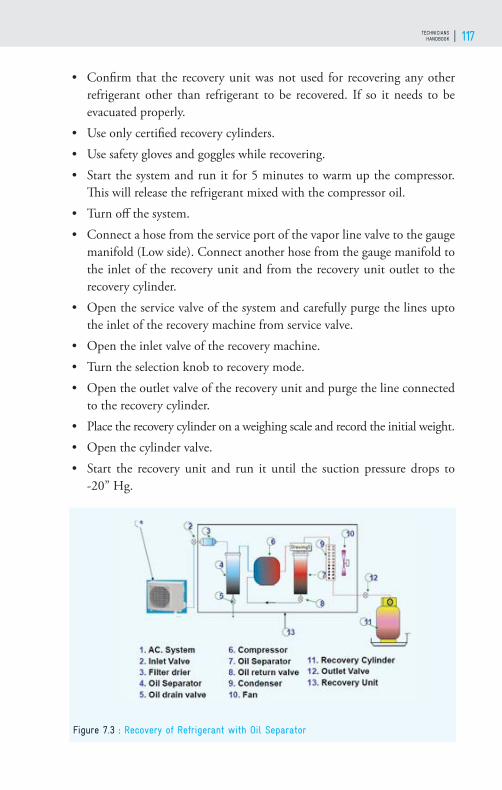
TECHNICIANS HANDBOOK 117
• Confi rm that the recovery unit was not used for recovering any other refrigerant other than refrigerant to be recovered. If so it needs to be evacuated properly.
• Use only certifi ed recovery cylinders. • Use safety gloves and goggles while recovering.• Start the system and run it for 5 minutes to warm up the compressor.
Th is will release the refrigerant mixed with the compressor oil. • Turn off the system.• Connect a hose from the service port of the vapor line valve to the gauge
manifold (Low side). Connect another hose from the gauge manifold to the inlet of the recovery unit and from the recovery unit outlet to the recovery cylinder.
• Open the service valve of the system and carefully purge the lines upto the inlet of the recovery machine from service valve.
• Open the inlet valve of the recovery machine.• Turn the selection knob to recovery mode.• Open the outlet valve of the recovery unit and purge the line connected
to the recovery cylinder.• Place the recovery cylinder on a weighing scale and record the initial weight.• Open the cylinder valve.• Start the recovery unit and run it until the suction pressure drops to
-20” Hg.
Figure 7.3 : Recovery of Refrigerant with Oil Separator

GOOD SERVICE PRACTICES AND INSTALLATION OF ROOM AIR-CONDITIONERS WITH HCFC–22 AND FLAMMABLE REFRIGERANTS118
• Wait for a while, if the pressure increases, start the recovery unit and recover until the pressure drops to -20” Hg. Record the fi nal weight. Never fi ll a cylinder more than 80% of its capacity.
• Fill the system with Oxygen Free Dry Nitrogen (OFDN) to break the vacuum and maintain a positive pressure of 2 to 5 psig.
• Close the service valve on the ODU.
Th e fi gure 7.3 shows another design of recovery machine with oil separator. Th e working principle is similar to the simple vapour recover machine. All the components of the machine are labeled in the schematic diagram for ease of understanding.
SAFE VENTING IN CASE OF ROOM AC CHARGED WITH R-290R-290 is non-ODS and has negligible global warming potential. Hence it need not be recovered and can be safely released into the atmosphere. It is highly fl ammable therefore it should be vented to safe outside open area and not to be released indoors, working area and near sources of ignition. Connect a long hose to the service valve of the AC and vent the refrigerant gradually. Use piercing plier/valve for appliances without service valve. After venting the refrigerant, it is necessary to remove the residual refrigerant remaining in the system. Th is is to prevent the risk of fl ash fi re during de-brazing of system lines. Using a vacuum pump, evacuate the system to about -20” of Mercury (Hg). After evacuation break the vacuum by fi lling the system with dry Nitrogen to a pressure of about 5 psig. It is important to break the vacuum with dry nitrogen or else air will enter the system and contaminate the refrigerant circuit. Ensure that the work area is well ventilated and the discharge from the vacuum pump does not get accumulated near the work area.
Figure 7.4 : Cut section of strainer

TECHNICIANS HANDBOOK 119
Repair and/or Replacement of Inoperative Spares
Release the OFDN from the system and disconnect the lines from the service valves. Th e inoperative spare parts should be replaced with genuine and recommended spares. Each time a system is being repaired, a new strainer and fi lter should be installed. Install a fi lter with a molecular sieve. Th is will desiccate and purify the refrigerant.
Th ere should be very less chances of capillary getting choked due to internal frost formation. Th e selection of drier/strainer depends on the basis of two system characteristics, 1) type and amount of contaminants that can be expected to develop in the system and 2) maximum operating pressure of the system. A strainer having adequate screen area to catch and hold moisture and other foreign particles that accumulate during the life of the unit and yet permit the refrigerant fl ow to continue without excessive pressure drop, it is necessary to consider the size and quantity of the contaminants. Strainer wire mesh is normally made of stainless steel, brass or phosphor bronze and sizes are from 100 x 90 to 150 x 140 etc. Th e fi lter/strainer must be replaced during servicing if system is opened for recharging.
Cleaning and Flushing
Upon dismantling the system, all the parts of the system must be cleaned and then polished using emery cloth / paper. Th e system must be fl ushed using OFDN (Purity: 99.995%, Dew Point: - 40°C at least) at a pressure of about 10 bar (150 psi). Th e Nitrogen cylinders as shown in Figure 7.5 fi tted with two stages regulator should be used. It is a must to have proper
Figure 7.5 : Nitrogen Cylinder with two stage pressure regulator
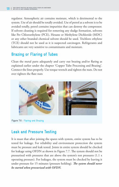
GOOD SERVICE PRACTICES AND INSTALLATION OF ROOM AIR-CONDITIONERS WITH HCFC–22 AND FLAMMABLE REFRIGERANTS120
regulator. Atmospheric air contains moisture, which is detrimental to the system. Use of air should be totally avoided. Use of petrol as a solvent is to be avoided totally, petrol contains impurities that can destroy the compressor. If solvent cleaning is required for removing any sludge formation, solvents like Per Chloroethylene (PCE), Hexane or Methylene Dichloride (MDC) or any other branded chemical solvent should be used. Trichloro ethylene (TCE) should not be used as it is suspected carcinogen. Refrigerants and lubricants are very sensitive to contaminants and moisture.
Brazing or Flaring of Tubes
Clean the metal parts adequately and carry out brazing and/or fl aring as explained earlier under the chapter ‘Copper Tube Processing and Brazing’. Connect the lines properly. Use torque wrench and tighten the nuts. Do not over tighten the fl are nuts
Leak and Pressure Testing
It is must that after joining the spares with system, entire system has to be tested for leakage. For reliability and environment protection the system must be pressure and leak tested. Joints in entire system should be checked for leakage using OFDN as shown in Figure 7.7. Th e system should not be pressurized with pressures that are above the system’s test pressures (1.1 x operating pressure). For leakages, the system must be checked by leaving it under pressure for 15 minutes (pressure holding). Th e system should never be started when pressurized with OFDN.
Figure 7.6 : Flaring and Brazing
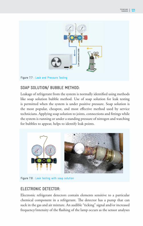
TECHNICIANS HANDBOOK 121
SOAP SOLUTION/ BUBBLE METHOD: Leakage of refrigerant from the system is normally identifi ed using methods like soap solution bubble method. Use of soap solution for leak testing is permitted when the system is under positive pressure. Soap solution is the most popular, cheapest, and most eff ective method used by service technicians. Applying soap solution to joints, connections and fi ttings while the system is running or under a standing pressure of nitrogen and watching for bubbles to appear, helps to identify leak points.
ELECTRONIC DETECTOR: Electronic refrigerant detectors contain elements sensitive to a particular chemical component in a refrigerant. Th e detector has a pump that can suck in the gas and air mixture. An audible “ticking” signal and/or increased frequency/intensity of the fl ashing of the lamp occurs as the sensor analyses
Figure 7.7 : Leak and Pressure Testing
Figure 7.8 : Leak testing with soap solution

GOOD SERVICE PRACTICES AND INSTALLATION OF ROOM AIR-CONDITIONERS WITH HCFC–22 AND FLAMMABLE REFRIGERANTS122
higher concentrations of refrigerant, indicating the source and location of the leak.
Th e most common locations of leakages in joints are at:
1. Flare connections/nuts2. Service valve: O-rings, access fi tting, mounting3. Cracked brazed joint in tubing4. Deteriorated evaporator and / or condenser end bends5. Tubes rubbing with each other or with other materials
When refrigerant leaks out, it increases the cost of repairing and servicing. It also has harmful eff ects on the environment. Th e effi ciency of the system drops and power consumption increases. Th erefore, CO2 consumption increases and there is a greater impact on environment or climate change. Hence, care must be taken to avoid refrigerant leakages.
Evacuation and Vacuum Holding
Evacuation is a process by which pressure in the sealed system is reduced, causing moisture to boil off into vapor. It removes air, moisture and other non-condensable gases from the system. Frozen moisture in the system may lead to one of the following problems:• Choked capillary tube, metering device and strainers• Choked fi lter driers• Reduced system eff ectiveness and effi ciency
To speed up evacuation, large valve port/hoses (9.52 mm or 3/8”) must
Figure 7.9 : Electronic refrigerant detector
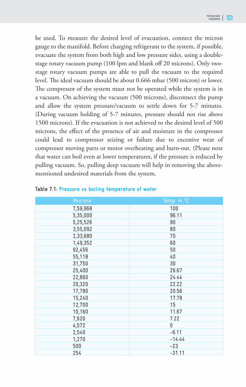
TECHNICIANS HANDBOOK 123
be used. To measure the desired level of evacuation, connect the micron gauge to the manifold. Before charging refrigerant to the system, if possible, evacuate the system from both high and low pressure sides, using a double-stage rotary vacuum pump (100 lpm and blank off 20 microns). Only two-stage rotary vacuum pumps are able to pull the vacuum to the required level. Th e ideal vacuum should be about 0.666 mbar (500 micron) or lower. Th e compressor of the system must not be operated while the system is in a vacuum. On achieving the vacuum (500 microns), disconnect the pump and allow the system pressure/vacuum to settle down for 5-7 minutes. (During vacuum holding of 5-7 minutes, pressure should not rise above 1500 microns). If the evacuation is not achieved to the desired level of 500 microns, the eff ect of the presence of air and moisture in the compressor could lead to compressor seizing or failure due to excessive wear of compressor moving parts or motor overheating and burn-out. (Please note that water can boil even at lower temperatures, if the pressure is reduced by pulling vacuum. So, pulling deep vacuum will help in removing the above-mentioned undesired materials from the system.
Table 7.1: Pressure vs boiling temperature of water
Microns Temp. in OC7,59,968 1005,35,000 96.115,25,526 903,55,092 802,33,680 701,49,352 6092,456 5055,118 4031,750 3025,400 26.6722,860 24.4420,320 22.2217,780 20.5615,240 17.7812,700 1510,160 11.677,620 7.224,572 02,540 -6.111,270 -14.44500 -23254 -31.11
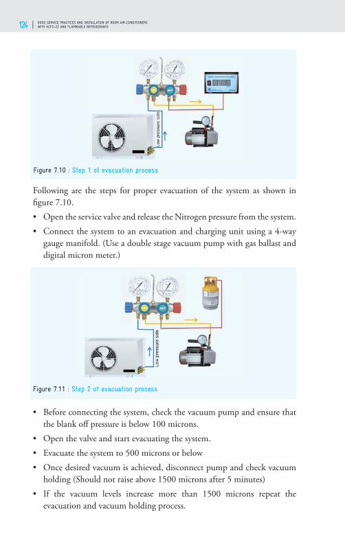
GOOD SERVICE PRACTICES AND INSTALLATION OF ROOM AIR-CONDITIONERS WITH HCFC–22 AND FLAMMABLE REFRIGERANTS124
Following are the steps for proper evacuation of the system as shown in fi gure 7.10.• Open the service valve and release the Nitrogen pressure from the system.• Connect the system to an evacuation and charging unit using a 4-way
gauge manifold. (Use a double stage vacuum pump with gas ballast and digital micron meter.)
• Before connecting the system, check the vacuum pump and ensure that the blank off pressure is below 100 microns.
• Open the valve and start evacuating the system.• Evacuate the system to 500 microns or below• Once desired vacuum is achieved, disconnect pump and check vacuum
holding (Should not raise above 1500 microns after 5 minutes)• If the vacuum levels increase more than 1500 microns repeat the
evacuation and vacuum holding process.
Figure 7.10 : Step 1 of evacuation process
Figure 7.11 : Step 2 of evacuation process

TECHNICIANS HANDBOOK 125
After the vacuum gauge shows the vacuum, then close the valve and remove the micron gauge. Th en attach the charging cylinder with valve in close position as shown in fi gure 7.11. Run the vacuum pump for two minutes with high side valve in open position to remove the non-condensable gases from the charging hose. By doing this there will be no need to purge the refrigerant from the charging hose.
Refrigerant Charging
For better performance of the air-conditioner, charging with accurate quantity of refrigerant is important. Charge always in a well evacuated system. Sweep charge or charge by feel, is not recommended. Charging should be done slowly and gradually, so that no liquid goes into the compressor. Since there is no eff ect of atmosphere (pressure /temperature) on mass or weight of the refrigerant, weight system must be deployed for measuring the amount of refrigerant while gas charging as shown in fi gure 7.12. A digital weighing scale/ balance for accurate quantity of charge must be used. Th is is a must for effi cient functioning of the air-conditioner and it is a GSP. In case the system gets over charged, the excess charge of refrigerant should not be vented out into the atmosphere but recovered. Refrigerant should enter the compressor only in a vapour state. After 5 minutes of refrigerant charging, pressures and temperatures of refrigerant must be checked. High or low pressures and temperatures indicate that the system is overcharged or undercharged. Undercharged systems are less effi cient, have higher running costs and might not be able to meet the load. Overcharged
Figure 7.12 : Charging of refrigerant into the air-conditioner
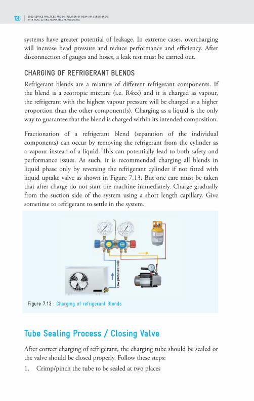
GOOD SERVICE PRACTICES AND INSTALLATION OF ROOM AIR-CONDITIONERS WITH HCFC–22 AND FLAMMABLE REFRIGERANTS126
systems have greater potential of leakage. In extreme cases, overcharging will increase head pressure and reduce performance and effi ciency. After disconnection of gauges and hoses, a leak test must be carried out.
CHARGING OF REFRIGERANT BLENDSRefrigerant blends are a mixture of diff erent refrigerant components. If the blend is a zeotropic mixture (i.e. R4xx) and it is charged as vapour, the refrigerant with the highest vapour pressure will be charged at a higher proportion than the other component(s). Charging as a liquid is the only way to guarantee that the blend is charged within its intended composition.
Fractionation of a refrigerant blend (separation of the individual components) can occur by removing the refrigerant from the cylinder as a vapour instead of a liquid. Th is can potentially lead to both safety and performance issues. As such, it is recommended charging all blends in liquid phase only by reversing the refrigerant cylinder if not fi tted with liquid uptake valve as shown in Figure 7.13. But one care must be taken that after charge do not start the machine immediately. Charge gradually from the suction side of the system using a short length capillary. Give sometime to refrigerant to settle in the system.
Tube Sealing Process / Closing Valve
After correct charging of refrigerant, the charging tube should be sealed or the valve should be closed properly. Follow these steps:1. Crimp/pinch the tube to be sealed at two places
Figure 7.13 : Charging of refrigerant Blends

TECHNICIANS HANDBOOK 127
2. Th e pinching tool must not be removed until the tube is sealed3. Braze or seal the tube4. Remove the pinching and / or crimping tool5. Final leak test must be done
OR1. Close the three-way service valve properly2. Check for leaks3. Put the lock-nut4. Final leak test must be done
Routine Check-up for Proper Functioning
As part of a routine checkup, measure temperatures of supply and return air after 20 minutes. Measure the current drawn by the air-conditioner. Keep a record on the job cards. Label the system and leave it in order. Record all observations.
Record Details of Work Done / Report Writing
It is recommended that the service personnel should maintain a record book or log book for serviced AC and enter pre-and post repair details as shown in the Table 7.2.
Figure 7.14 : Recording Observations
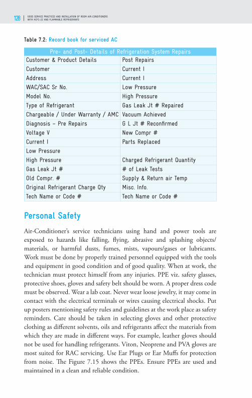
GOOD SERVICE PRACTICES AND INSTALLATION OF ROOM AIR-CONDITIONERS WITH HCFC–22 AND FLAMMABLE REFRIGERANTS128
Table 7.2: Record book for serviced AC
Pre- and Post- Details of Refrigeration System RepairsCustomer & Product Details Post Repairs
Customer Current I
Address Current I
WAC/SAC Sr No. Low Pressure
Model No. High Pressure
Type of Refrigerant Gas Leak Jt # Repaired
Chargeable / Under Warranty / AMC Vacuum Achieved
Diagnosis – Pre Repairs G L Jt # Reconfi rmed
Voltage V New Compr #
Current I Parts Replaced
Low Pressure
High Pressure Charged Refrigerant Quantity
Gas Leak Jt # # of Leak Tests
Old Compr. # Supply & Return air Temp
Original Refrigerant Charge Qty Misc. Info.
Tech Name or Code # Tech Name or Code #
Personal Safety
Air-Conditioner’s service technicians using hand and power tools are exposed to hazards like falling, fl ying, abrasive and splashing objects/materials, or harmful dusts, fumes, mists, vapours/gases or lubricants. Work must be done by properly trained personnel equipped with the tools and equipment in good condition and of good quality. When at work, the technician must protect himself from any injuries. PPE viz. safety glasses, protective shoes, gloves and safety belt should be worn. A proper dress code must be observed. Wear a lab coat. Never wear loose jewelry, it may come in contact with the electrical terminals or wires causing electrical shocks. Put up posters mentioning safety rules and guidelines at the work place as safety reminders. Care should be taken in selecting gloves and other protective clothing as diff erent solvents, oils and refrigerants aff ect the materials from which they are made in diff erent ways. For example, leather gloves should not be used for handling refrigerants. Viton, Neoprene and PVA gloves are most suited for RAC servicing. Use Ear Plugs or Ear Muff s for protection from noise. Th e Figure 7.15 shows the PPEs. Ensure PPEs are used and maintained in a clean and reliable condition.
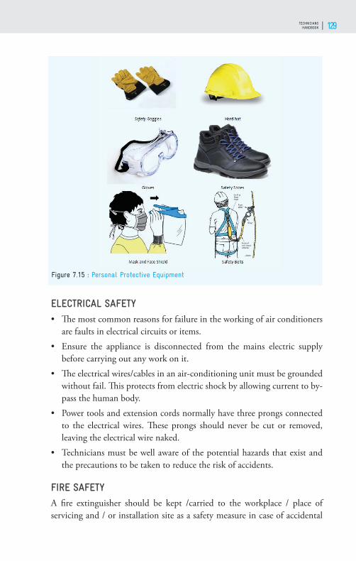
TECHNICIANS HANDBOOK 129
ELECTRICAL SAFETY• Th e most common reasons for failure in the working of air conditioners
are faults in electrical circuits or items.• Ensure the appliance is disconnected from the mains electric supply
before carrying out any work on it. • Th e electrical wires/cables in an air-conditioning unit must be grounded
without fail. Th is protects from electric shock by allowing current to by-pass the human body.
• Power tools and extension cords normally have three prongs connected to the electrical wires. Th ese prongs should never be cut or removed, leaving the electrical wire naked.
• Technicians must be well aware of the potential hazards that exist and the precautions to be taken to reduce the risk of accidents.
FIRE SAFETYA fi re extinguisher should be kept /carried to the workplace / place of servicing and / or installation site as a safety measure in case of accidental
Figure 7.15 : Personal Protective Equipment

GOOD SERVICE PRACTICES AND INSTALLATION OF ROOM AIR-CONDITIONERS WITH HCFC–22 AND FLAMMABLE REFRIGERANTS130
fi re. Fire extinguishers are classifi ed in three groups, based on the cause of fi re that requires to be extinguished:• Class A fi re extinguishers are designed for use on fi re occurring from
burning wood, paper, or other ordinary combustibles.• Class B fi re extinguishers are designed for use on fi re due to fl ammable
liquids like grease, petrol or oil.• Class C fi re extinguishers are designed for use on electrical fi res.• Use of ABC powder-type fi re extinguisher is ideal.
ADDITIONAL SAFETY GUIDELINES FOR GOOD SERVICE PRACTICES1. Take care while opening the system as the pressure inside the system is
generally higher than atmospheric pressure2. Liquid refrigerant causes frostbite if it comes into contact with human
skin. For protection, wear personal protective equipment (PPE)3. Th e refrigerant in the air-conditioner may be contaminated with acids.
Ensure it does not come into contact with the skin4. Th e compressor oil may also be acidic, so wear gloves and goggles when
removing and/or repairing a faulty compressor5. Always use a two-stage pressure regulator (up to 50 bar) when using
nitrogen
Figure 7.16 : Fire Extinguisher and Symbols

TECHNICIANS HANDBOOK 131
6. Ensure that all hoses are free from cracks and have adequate strength to withstand high pressures
7. Charge the system with correct quantity of good quality refrigerant8. Seal the charging point by brazing/closing of valve and then test for
leakage9. Label the air-conditioner correctly with information of the refrigerant
used10. Make sure the refrigerant cylinder/can valves are in good condition and
are capped when not in use11. Do not modify cylinder/can or valves12. Do not re-fi ll disposable cylinders/cans
ADDITIONAL SAFETY MEASURES FOR FLAMMABLE REFRIGERANTS Servicing room Air-conditioners with fl ammable refrigerants need adequate training and experience. Some safety measures to be strictly taken during servicing of air conditioners with fl ammable refrigerants as given below.• Work in well ventilated area, outdoors or use forced / induced ventilation
system.• No ignition sources should be there within 2 meter radius of working
area.• Ensure that suitable fi re extinguishing equipment (ABC-powder type)
is available.• Cut off power supply connection before starting of work. • Discharge the capacitor completely before conducting repair work/
Figure 7.17 : Safety measures for fl ammable refrigerants

GOOD SERVICE PRACTICES AND INSTALLATION OF ROOM AIR-CONDITIONERS WITH HCFC–22 AND FLAMMABLE REFRIGERANTS132
servicing.• Keep refrigerant sensor detectors for fl ammable refrigerant.• Display “no smoking “or “access denied “signs.
Ignition source include fl ames due to brazing torches, match or cigarette lighter or sparks from unsealed components such as electrical switches, relays, OLPs or loose wires or even static electricity. Th e basic safety logic is that in order to have an explosion, there should be a combustible mixture of gas and air (Oxygen) within the fl ammable limits, and simultaneously, there should be an ignition source with suffi cient intensity to initiate and sustain the explosion. Th erefore, the fi rst step is to avoid the possibility of any leak. Even if there is a leak, make sure that a combustible mixture is not formed. In addition to this, the area should be controlled in such a way that the sources of ignition are eliminated or avoided.
Safety of Tools and Equipment• Th e right tools must be used for doing the job.• Th ese must be operated according to the instructions of the manufacturers.• Hacksaw blades, knives, drill bits or other tools must be directed away
from walkways and other technicians working in close proximity. Dull tools can be more hazardous than sharp ones.
• Technicians operating the tools and equipment have personal responsibility of using them carefully by learning the appropriate skills.
SAFETY WHILE USING POWER TOOLS• Disconnect tools when not in use, before servicing and cleaning and
when changing accessories.• People who are not involved with the ongoing work should be kept away
from the worksite.• Secure work with clamps or a vise, freeing both hands to operate the tool.• Do not keep your hand on the tool switch while carrying the plugged-in
tool.• Keep tools sharp and clean.• Remove damaged electric tools and tag them: ‘Do Not Use’.• Do not carry or pull portable tools by the cord.• Do not use electric cords to hoist or lower tools.• Do not pull the cord or hose to disconnect the tool.

TECHNICIANS HANDBOOK 133
• Keep cords and hoses away from heat, oil and sharp edges.• Replace damaged cords immediately.
Safe Handling and Storage of Refrig-erant Cylinders
Cylinders fi lled with the refrigerant have to be handled with utmost care. Refrigerants like HFC-32 and R-410A have higher operating pressures. Th ese refrigerants should not be stored in cylinders rated for refrigerants like HCFC-22. Always check the pressure rating of the cylinder before fi lling the cylinder with any refrigerant. Th e test pressure of any cylinder should be 2 to 2.5 times the service pressure. Following guidelines are recommended for storage of refrigerant cylinders:• Gas cylinders should be stored in a covered area
where the temperature is below 50°C.• Cylinders must be kept away from sources of ignition, including static
discharges.• Th e work area and where the cylinders are stored, should be a ‘no
smoking’ zone.• Certifi ed stickers on the cylinders must not be removed or destroyed
When the cylinder is not in use, ensure that the cap is closed.• Gas cylinders must be stored and transported only in an upright position.
Figure 7.19 : Safety storage for fl ammable refrigerants
Figure 4.18 : Storage of refrigerant cylinder
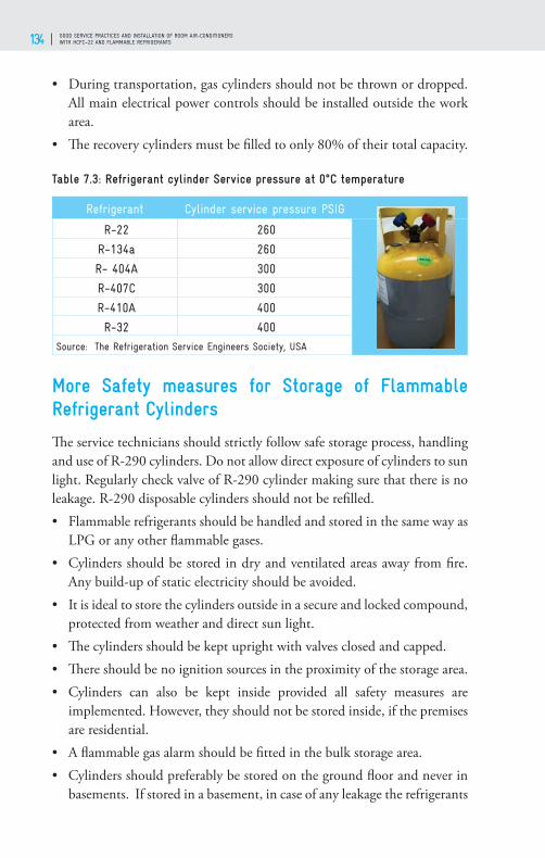
GOOD SERVICE PRACTICES AND INSTALLATION OF ROOM AIR-CONDITIONERS WITH HCFC–22 AND FLAMMABLE REFRIGERANTS134
• During transportation, gas cylinders should not be thrown or dropped. All main electrical power controls should be installed outside the work area.
• Th e recovery cylinders must be fi lled to only 80% of their total capacity.
Table 7.3: Refrigerant cylinder Service pressure at 0°C temperature
Refrigerant Cylinder service pressure PSIG
R-22 260
R-134a 260
R- 404A 300
R-407C 300
R-410A 400
R-32 400
Source: The Refrigeration Service Engineers Society, USA
More Safety measures for Storage of Flammable Refrigerant Cylinders
Th e service technicians should strictly follow safe storage process, handling and use of R-290 cylinders. Do not allow direct exposure of cylinders to sun light. Regularly check valve of R-290 cylinder making sure that there is no leakage. R-290 disposable cylinders should not be refi lled. • Flammable refrigerants should be handled and stored in the same way as
LPG or any other fl ammable gases. • Cylinders should be stored in dry and ventilated areas away from fi re.
Any build-up of static electricity should be avoided. • It is ideal to store the cylinders outside in a secure and locked compound,
protected from weather and direct sun light. • Th e cylinders should be kept upright with valves closed and capped. • Th ere should be no ignition sources in the proximity of the storage area. • Cylinders can also be kept inside provided all safety measures are
implemented. However, they should not be stored inside, if the premises are residential.
• A fl ammable gas alarm should be fi tted in the bulk storage area. • Cylinders should preferably be stored on the ground fl oor and never in
basements. If stored in a basement, in case of any leakage the refrigerants

TECHNICIANS HANDBOOK 135
will accumulate there and will not be easily dispersed. • Th is can eventually lead to an explosion, if there is any spark in the
room. Cylinders should not be stored with other fl ammable substances, particularly fl ammable gases.
• Storage of empty cylinders should be segregated from that of the fi lled-up cylinders.
• Follow the Petroleum and Explosive Safety Organization (PESO) Regulations for transport of fl ammable and high-pressure refrigerants. Do not transport refrigerant in the passenger compartment of a vehicle.
• Always keep First - Aid box. Use dry powder fi re extinguisher.

GOOD SERVICE PRACTICES AND INSTALLATION OF ROOM AIR-CONDITIONERS WITH HCFC–22 AND FLAMMABLE REFRIGERANTS136
TECHNICIANS HANDBOOK 137
GOOD SERVICE PRACTICES FOR ENERGY EFFICIENT OPERATION OF ROOM AIR-CONDITIONERS
08

GOOD SERVICE PRACTICES AND INSTALLATION OF ROOM AIR-CONDITIONERS WITH HCFC–22 AND FLAMMABLE REFRIGERANTS138
Background
Room air-conditioner consumes signifi cantly higher energy as compared to other household appliances. Th e effi ciency of the Room Air-conditioner decreases due to age, defects and poor service practices. To maintain the designed energy effi ciency of Room Air-conditioner it is necessary to follow good service practices (GSP) and periodic preventive maintenance. With proper maintenance of Air-conditioner (AC), there will be signifi cant saving of energy use. Th e household energy consumption can be lowered by effi cient operation and adopting high Bureau of Energy Effi ciency (BEE) energy star labeled Room Air-conditioner. Most of the refrigerants have harmful impact on the environment, so during installation and/or servicing, greater care should be taken to avoid release of refrigerants to the environment. Following good services practices for energy effi cient operations will give service satisfaction to the customer and will help the technician in getting enhanced and repeated business.
Sources of Emissions – Global Warming Contribution
Th ere are direct emissions of refrigerant used in ACs during installation due to leakages, servicing and disposal of ACs at the end of life. As HCFCs and HFCs are having high global warming potential (e.g. GWP of HCFC-22 is 1820, R-410A is 2080). Such emissions to environment contribute towards global warming.
Indirect emission and contribution in global warming are due to electricity consumption during the working life time of the air-conditioner. Generation of electricity in the power plants results in Greenhouse Gases
Figure 8.1 : Sources of Emission – Window Room Air-Conditioner
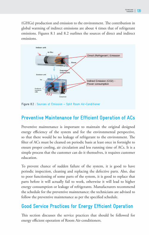
TECHNICIANS HANDBOOK 139
(GHGs) production and emission to the environment. Th e contribution in global warming of indirect emissions are about 4 times that of refrigerant emissions. Figures 8.1 and 8.2 outlines the sources of direct and indirect emissions.
Preventive Maintenance for Effi cient Operation of ACs
Preventive maintenance is important to maintain the original designed energy effi ciency of the system and for the environmental perspective, so that there would be no leakage of refrigerant to the environment. Th e fi lter of ACs must be cleaned on periodic basis at least once in fortnight to ensure proper cooling, air circulation and less running time of ACs. It is a simple process that the customer can do it themselves, it requires customer education.
To prevent chance of sudden failure of the system, it is good to have periodic inspection, cleaning and replacing the defective parts. Also, due to poor functioning of some parts of the system, it is good to replace that parts before it will actually fail to work, otherwise it will lead to higher energy consumption or leakage of refrigerants. Manufacturers recommend the schedule for the preventive maintenance; the technicians are advised to follow the preventive maintenance as per the specifi ed schedule.
Good Service Practices for Energy Effi cient Operation
Th is section discusses the service practices that should be followed for energy effi cient operation of Room Air-conditioners.
Figure 8.2 : Sources of Emission – Split Room Air-Conditioner

GOOD SERVICE PRACTICES AND INSTALLATION OF ROOM AIR-CONDITIONERS WITH HCFC–22 AND FLAMMABLE REFRIGERANTS140
CLEANING OF CONDENSER AND EVAPORATOR COILS
Dust debris or contaminant creates fouling on evaporator surfaces, which reduce airfl ow and poor heat transfer in condenser and evaporator resulting in less cooling and reduction in overall performance and effi ciency of AC. Th e excessive accumulation of dirt on the evaporator may have ice formation on coil surface.
Dust, debris can be sucked into the fi ns of a condensing unit coil as air is drawn through them by the fan. Th ese obstructions will lower the eff ectiveness of the coil, elevate condensing temperature, and reduce cooling effi ciency. A visual inspection is generally adequate to determine whether the coil must be cleaned, though cleaning a relatively unobstructed coil is likely to improve effi ciency.
Both the evaporator and condensers coil should be cleaned at least twice in a year. Th e fi lters of ACs should be cleaned frequently.
ENERGY EFFICIENCY CONSIDERATION ON ELECTRICAL COMPONENTS
While servicing it is to be checked that all wires/cables are properly connected, any loose connections should be avoided completely. Th ere will be energy loss due to loose connections of wires and also chances of overheating and sparking which is a heavy danger in case of fl ammable refrigerant.
When replacing electrical parts like capacitor only select the parts recommended by the manufacturer. A wrong size capacitor could cause the compressor/fan motor to overheat, decrease the effi ciency and shorten its
Figure 8.3 : Cleaning of condenser and evaporator coils

TECHNICIANS HANDBOOK 141
life. Also, the relay specifi ed by the manufacturer should be used.
AVOID RESTRICTION OF AIRFLOW OVER CONDENSING COIL AND EVAPORATOR COIL:
Th ere should not be any obstruction to the circulation of air, restriction on air fl ow will reduce performance of the AC. Th e space around the ODU must be more than 150-250 mm (6”–9.8”) in the rear and more than 1500 mm (59”) in front of the unit. Th ere should be adequate space, more than 150 mm (6”), around the IDU. Th e distance between the ceiling and the IDU should be more than 50 mm (2”) in the case of front suction or grille
design and more than 150 mm (6”) in the case of top suction or fl at front panel design.
AIM FOR ZERO REFRIGERANT EMISSIONS
Leakage of refrigerant is harmful to environment. Th e reduction of refrigerant charge in the system due to leakage results in decrease in system performance and effi ciency. It is important to follow the correct method
Figure 8.4 : Cleaning of Air fi lter
Figure 8.5 : Aim for zero refrigerant
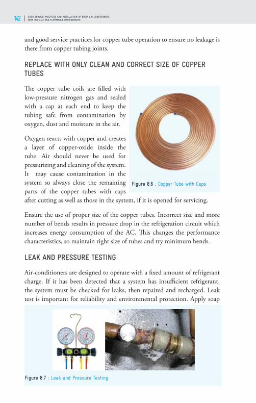
GOOD SERVICE PRACTICES AND INSTALLATION OF ROOM AIR-CONDITIONERS WITH HCFC–22 AND FLAMMABLE REFRIGERANTS142
and good service practices for copper tube operation to ensure no leakage is there from copper tubing joints.
REPLACE WITH ONLY CLEAN AND CORRECT SIZE OF COPPER TUBES
Th e copper tube coils are fi lled with low-pressure nitrogen gas and sealed with a cap at each end to keep the tubing safe from contamination by oxygen, dust and moisture in the air.
Oxygen reacts with copper and creates a layer of copper-oxide inside the tube. Air should never be used for pressurizing and cleaning of the system. It may cause contamination in the system so always close the remaining parts of the copper tubes with caps after cutting as well as those in the system, if it is opened for servicing.
Ensure the use of proper size of the copper tubes. Incorrect size and more number of bends results in pressure drop in the refrigeration circuit which increases energy consumption of the AC. Th is changes the performance characteristics, so maintain right size of tubes and try minimum bends.
LEAK AND PRESSURE TESTING
Air-conditioners are designed to operate with a fi xed amount of refrigerant charge. If it has been detected that a system has insuffi cient refrigerant, the system must be checked for leaks, then repaired and recharged. Leak test is important for reliability and environmental protection. Apply soap
Figure 8.6 : Copper Tube with Caps
Figure 8.7 : Leak and Pressure Testing
TECHNICIANS HANDBOOK 143
solution to joints, connections and fi ttings while system is running or under a standing pressure of nitrogen to identify leak points through appearance of bubbles. Electronic leak detector can also be used for leak detection.
USE OXYGEN-FREE DRY NITROGEN (OFDN)
After repairing and joining processes the system must be tightened and pressure tested. Th is is to be done by pressurizing the system with OFDN to a pressure higher than the operating pressure and check the system for pressure holding for at least fi fteen minutes to ensure there is no leak in the system. Keep noticing the pressure gauge for the pressure drop, if any.
AVOID SLUDGE AND OXIDE FORMATION
After long operation and due to some contaminants, there may be sludge and oxide formation inside the system that can reduce the heat transfer rate and thus cooling capacity. So, it is required to clean the condenser and evaporator coil with solvents and fl ush the system thoroughly with OFDN when system is opened for servicing. Slowly pass low pressure OFDN through the tubes.
PROPER EVACUATION OF THE SYSTEM:
For better performance of air-conditioner the system should be free from air, moisture, and non-condensable gases. Presence of moisture leads to choking of capillary, strainers, and fi lter/drier. Th e non-condensable gases increase system pressure, higher condenser and discharge pressure and result in decrease in energy effi ciency of the system. Th is results in increased power consumption and, also, lesser cooling capacity of the system. Th erefore, deep evacuation (proper vacuum) of system is important before charging the refrigerant. Th e evacuation must be carried out to 500 or lower microns level. Evacuate the system at least for 30 minutes to ensure adequate vacuum, if micron gauge is not available.
USE QUALITY REFRIGERANTS AND COMPATIBLE LUBRICATION OIL
Contaminated refrigerant may contain non-condensable gases and moisture; these will result in sludge formation and creates chocking of capillary and sludge formation in the system. Ensure that refrigerants of proper quality and purity are used, cross contamination of refrigerants should be avoided, it may result in reduced performance and even failure of the system.

GOOD SERVICE PRACTICES AND INSTALLATION OF ROOM AIR-CONDITIONERS WITH HCFC–22 AND FLAMMABLE REFRIGERANTS144
Lubrication of moving parts is very important in room air-conditioning system. Always use good quality recommended lubricating oil. Th e change in oil may result in improper miscibility of refrigerant and lubricant. Th is would result in separation of oil in the cooling coil.
Replace strainer/fi lter so that there will be minimum possibility of moisture and other contaminants in the system while servicing the system.
REFRIGERANT CHARGE QUANTITY AS SPECIFIED ON THE OUTDOOR UNIT OF THE AIR-CONDITIONER
Th e capillary systems like ACs are very sensitive to charge quantity. Charge the quantity of refrigerant as per the manufacturer recommendation (specifi ed on the outdoor unit). Th e Figure 8.8 shows variation in energy effi ciency with higher and lower charge quantities, the energy effi ciency drops in both the cases It is necessary the ACs should be charged with refrigerant by weight.
Overcharging of refrigerant increases the compressor power consumption. High operating pressures/temperatures indicate that system is overcharged. Th ere is more chance of leakage from overcharged system. Undercharged will cause less cooling eff ect thus decrease the system effi ciency.
Important to note : Charging of refrigerant by weight is the right procedure for Room ACs.
Figure 8.8 : Energy Effi ciency Deviation with Charge Quantity
TECHNICIANS HANDBOOK 145
Education to Customer on Energy Saving
Following are few advices that the technicians should provide to the AC users for operating the systems effi ciently. 1. Doors and windows of air-conditioned spaces where AC is operating
should be closed so that there will be no outside hot air entering the space.
2. Run ceiling fan, it helps proper circulation of the air inside the room. Also, due to a little higher speed of air using ceiling fan, the temperature set point can be increased, by which we can lower energy consumption of Room AC.
3. Use LED lights which consume less energy and also generate less heat for same output lumens. LED lights consume less both lighting and air- conditioner energy.
4. While buying new air-conditioner, opt higher BEE Star rating system, which consumes less energy as compared to low star rating system. 5 Star rated Room AC consume about 20 to 25% lower energy than 1 Star AC.
5. Draw curtains, drapes and blinds if possible, this helps to lower the heat transfer through windows and walls, lowering the cooling energy required and thus less energy consumption.
6. Run the system at higher temperature set in a range 24-27°C. At lower temperature setting, it will consume more power.
7. Air fi lter should be cleaned by customer periodically and AC should be serviced at least twice in a year. Th e air fi lters accumulates dirt which restrict the air circulation.
8. Electricity saving is equivalent to lower electricity bill to the users. 9. Th e customer should be made aware that servicing of the air-
conditioner should be got done from certifi ed technicians.
Impact of Temperature settings on Energy Consumption
Th e thermostat temperature setting plays a critical role in cooling capacity requirement of the space to be air-conditioned, lower the set point temperature, more is the cooling requirement and more energy

GOOD SERVICE PRACTICES AND INSTALLATION OF ROOM AIR-CONDITIONERS WITH HCFC–22 AND FLAMMABLE REFRIGERANTS146
consumption for the space. Making the room temperature set to 26°C the energy savings will be around 15 to 20% lower than the room temperature set of 20°C.
Air-conditioner Energy Labelling Standard
BEE started mandatory energy effi ciency Star rating from 2010 for room air-conditioner up to a rated cooling capacity of 10.465 kW. Th e room air conditioner of the vapour compression type which are of unitary air conditioner and split air-conditioner up to a rated cooling capacity of 10,465 Watts (9,000 kcal/hour) being manufactured, commercially purchased or sold in India shall –• meet the compliance requirements of the maximum operating conditions
test in accordance with IS 1391(Part1) for unitary air conditioner and IS 1391(Part2) for split air conditioner.
• be certifi ed against IS/ISO 9000 or above.
Th e BEE label to room air conditioner is maximum of 5 stars with an interval of 1 star, and the room air conditioner is rated from star 1 to star 5 based on their relative energy effi ciencies.
Earlier BEE used to label the system based on the Energy Effi ciency Ratio (EER), means the ratio of capacity (in Watts) to the power consumption at nominal voltage and frequency. From 2018 BEE labels the system based on the Indian Seasonal Energy Effi ciency Ratio (ISEER), means the ratio of the total annual amount of heat that the equipment may remove from
Figure 8.9 : The Impact of Indoor Temperature settings on Energy Consumption

TECHNICIANS HANDBOOK 147
the indoor air when operated for cooling in active mode to the total annual amount of energy consumed by the equipment during the same period.
Th e methodology for calculating the cooling seasonal total load, cooling seasonal energy consumption and ISEER shall be in accordance with the ISO 16358.
Th e labelling program is a dynamic system, every two years BEE revise and enhance energy effi ciency values which is illustrated in the fi gure 8.10.
Checklist for Good Service Practices
Action
Check air fi lter and perform cleaning
Check Condenser coil wash outdoor unit condenser coil annually at least once a year to maximize effi ciency and enhance AC working life;
Check Evaporator coil and clean it at least once a year;
Perform leak and pressure testing
Use Oxygen Free Dry Nitrogen to remove contaminants from the system
Ensure correct Refrigerant Charge as recommended by the manufacturer
Treat AC drain pans to prevent its clogging may be due to algae growth
Check compressor amps
Check condenser fan amps
Tighten electrical connections
Check capacitance of Capacitors
Educate customer on Energy Effi cient operations
Figure 8.10 : Star Level up-gradation for Split AC

GOOD SERVICE PRACTICES AND INSTALLATION OF ROOM AIR-CONDITIONERS WITH HCFC–22 AND FLAMMABLE REFRIGERANTS148

TECHNICIANS HANDBOOK 149
SOFT SKILLS
09
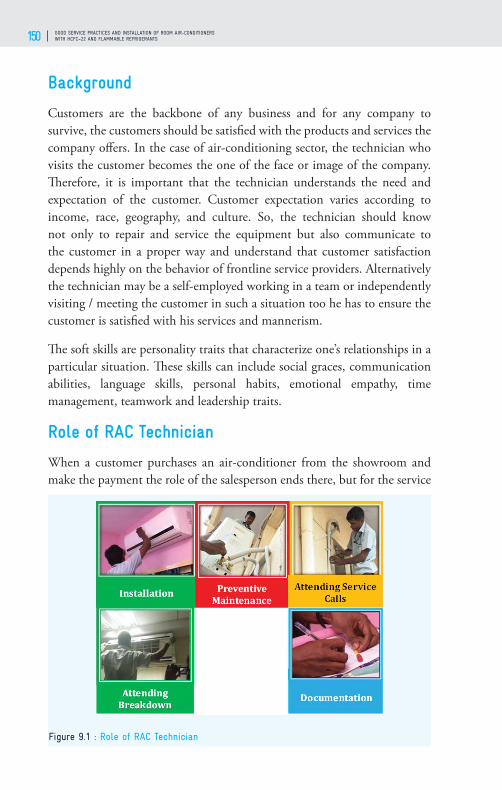
GOOD SERVICE PRACTICES AND INSTALLATION OF ROOM AIR-CONDITIONERS WITH HCFC–22 AND FLAMMABLE REFRIGERANTS150
Background
Customers are the backbone of any business and for any company to survive, the customers should be satisfi ed with the products and services the company off ers. In the case of air-conditioning sector, the technician who visits the customer becomes the one of the face or image of the company. Th erefore, it is important that the technician understands the need and expectation of the customer. Customer expectation varies according to income, race, geography, and culture. So, the technician should know not only to repair and service the equipment but also communicate to the customer in a proper way and understand that customer satisfaction depends highly on the behavior of frontline service providers. Alternatively the technician may be a self-employed working in a team or independently visiting / meeting the customer in such a situation too he has to ensure the customer is satisfi ed with his services and mannerism.
Th e soft skills are personality traits that characterize one’s relationships in a particular situation. Th ese skills can include social graces, communication abilities, language skills, personal habits, emotional empathy, time management, teamwork and leadership traits.
Role of RAC Technician
When a customer purchases an air-conditioner from the showroom and make the payment the role of the salesperson ends there, but for the service
Figure 9.1 : Role of RAC Technician
TECHNICIANS HANDBOOK 151
technician, it is the beginning of long-term relationship. His/her role starts with the identifi cation of a proper location for installation, installing the AC, educating the customer on proper usage, giving energy saving tips, doing preventive maintenance, attending breakdown calls etc.
Soft Skills
Th e technicians must understand what is “Good service” all about, it is not just knowing all about the equipment and servicing techniques but a combination of many factors with work ethics at the core of it.
Attitude: An eff ective customer relationship starts with the attitudes of the customer service representatives. Maintaining a positive attitude is about putting oneself in the customer’s position and viewing the problem from their point of view. Th is would help the service technician to make better decisions and know how to deal with diff erent customers. Attitude of the technician should be that of “Help and Support”.
Communication skills: Communication is the key component of an excellent service, as it is the art of conveying the message. As to how the technician can steer the conversation toward a positive outcome this is possible thorough eff ective communication. Being cheerful and calm even in a tough situation helps to win the customer.
Language skills: Politely communicating in the language that can be understood by the customers and peer group enhances the ability to explain and execute the work appropriately.
Time management: Visiting and /or completing the tasks in time as specifi ed is one of the important characteristics necessary for a technician to be successful.
Effective Communication Skills
Eye to eye contact: Eye to eye contact is important, it is also an important form of non-verbal communication and can create an instant connection between the technicians and their customer and provides a positive step towards building a successful human connection with a customer.
Body language: Body language is an added tool of communication. With a positive attitude, the technician will appear more amenable, amicable,

GOOD SERVICE PRACTICES AND INSTALLATION OF ROOM AIR-CONDITIONERS WITH HCFC–22 AND FLAMMABLE REFRIGERANTS152
responsive, and attuned to the needs and expectations of customers. Th is, in turn, would refl ect in their behavior towards customers, who would feel heard, respected, and cared for by the technician. A smiling face and the tone of voice can make a huge positive impact.
Silence: Silence though is not golden in customer service, sometimes it is better to keep silent, especially when there is a situation of arguments and if you feel your response is going to make customer uncomfortable.
Quick take away: Summarizing what was discussed, listening to what the customer have to say about the quality of work, will lead to doing a better next time. Pay attention to the needs of the customer make a special eff ort to hear what the customer are saying. Encourage them to continue and ask questions.
Communication with Customers
COMMUNICATION PRACTICES BEFORE START OF THE WORK
While visiting customers keeping an appointment is important. Th at is going to be the fi rst chance of impressing the customer. Check the customer location and give the costumer an appropriate time. Th e most important thing is to be on time, checking the route through GPS for route planning. Informing customer about visit charges.
Ring the bell and wait, introduce yourself and your company, greet the customer formally. Use customer title and surname, if someone does not have a professional title, use the title “Sir” or “Madam”. Show the ID card.
Figure 9.2 : Effective Communication Skills
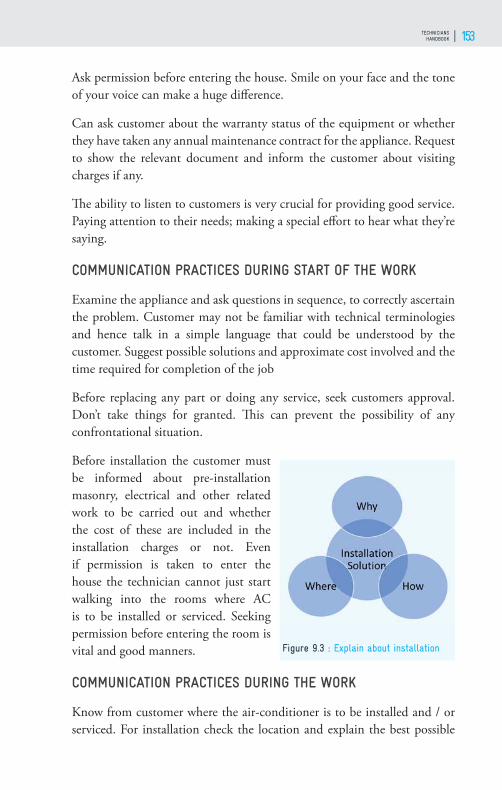
TECHNICIANS HANDBOOK 153
Ask permission before entering the house. Smile on your face and the tone of your voice can make a huge diff erence.
Can ask customer about the warranty status of the equipment or whether they have taken any annual maintenance contract for the appliance. Request to show the relevant document and inform the customer about visiting charges if any.
Th e ability to listen to customers is very crucial for providing good service. Paying attention to their needs; making a special eff ort to hear what they’re saying.
COMMUNICATION PRACTICES DURING START OF THE WORK
Examine the appliance and ask questions in sequence, to correctly ascertain the problem. Customer may not be familiar with technical terminologies and hence talk in a simple language that could be understood by the customer. Suggest possible solutions and approximate cost involved and the time required for completion of the job
Before replacing any part or doing any service, seek customers approval. Don’t take things for granted. Th is can prevent the possibility of any confrontational situation.
Before installation the customer must be informed about pre-installation masonry, electrical and other related work to be carried out and whether the cost of these are included in the installation charges or not. Even if permission is taken to enter the house the technician cannot just start walking into the rooms where AC is to be installed or serviced. Seeking permission before entering the room is vital and good manners.
COMMUNICATION PRACTICES DURING THE WORK
Know from customer where the air-conditioner is to be installed and / or serviced. For installation check the location and explain the best possible
Figure 9.3 : Explain about installation
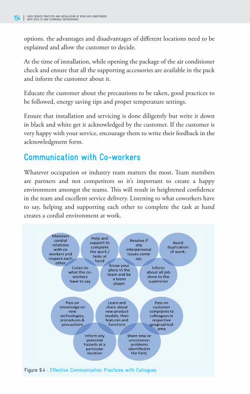
GOOD SERVICE PRACTICES AND INSTALLATION OF ROOM AIR-CONDITIONERS WITH HCFC–22 AND FLAMMABLE REFRIGERANTS154
options. the advantages and disadvantages of diff erent locations need to be explained and allow the customer to decide.
At the time of installation, while opening the package of the air conditioner check and ensure that all the supporting accessories are available in the pack and inform the customer about it.
Educate the customer about the precautions to be taken, good practices to be followed, energy saving tips and proper temperature settings.
Ensure that installation and servicing is done diligently but write it down in black and white get it acknowledged by the customer. If the customer is very happy with your service, encourage them to write their feedback in the acknowledgment form.
Communication with Co-workers
Whatever occupation or industry team matters the most. Team members are partners and not competitors so it’s important to create a happy environment amongst the teams. Th is will result in heightened confi dence in the team and excellent service delivery. Listening to what coworkers have to say, helping and supporting each other to complete the task at hand creates a cordial environment at work.
Figure 9.4 : Effective Communication Practices with Collogues

TECHNICIANS HANDBOOK 155
It is important viz. to resolve any interpersonal issues among team members. Early indications of problems and resolving them at the earliest are signs of team eff ectiveness.
Pass knowledge on new technologies, procedures, and precautions to team members. All humans are with diff erent skills and knowledge, and learning from other members of the team goes a long way forward in thinking innovatively and coming up with solutions that will suit the job and make customer happy. Discussing the problems faced in the fi eld with colleagues will help all to come up with better solutions.
Pass on customer complaints to colleagues in the respective geographical area. Working together produces good customer service. Strong teams, for example, assure consistency of communication with the customer, deadlines are more easy to be met and everyone takes responsibility for their actions.
Telephone Skills
Before answering a call relaxing the mind is important, if the phone call is answered in an agitated mood, it will aff ect the tone and voice. Th e phone call have to be answered with a smile.
Start the conversation by greeting the customer. Speaking clearly, with a vibrant tone and voice is an attribute to clear communication. Practice speaking skills at home, with friends or colleagues. While answering a phone call state name and organization and write down the caller’s name and other information the customer is providing. Have a writing pad and pencil ready to take notes or messages. Never answer a call while eating food or chewing gum.
Writing Skills
During installation or attending service complaints communicate the information like the nature of the complaint, corrective actions required to be taken, post completing the task type of work done, precautions to be taken and payment received from customers etc. Clear writing minimizes issues with customers, cuts complaints and promotes loyalty. All required format to be fi lled up immediately on completion of work. Th is will help to keep the maintenance records properly.

GOOD SERVICE PRACTICES AND INSTALLATION OF ROOM AIR-CONDITIONERS WITH HCFC–22 AND FLAMMABLE REFRIGERANTS156
Reading Skills
It is important to acquire good reading skills as it allows to understand written sentences and paragraphs in work related documents. Habit to read all product operating manuals, standard operating procedures, MSDS of diff erent types of solvents and refrigerants used in your workplaces.
Professionalism
Professionalism is particularly important for those who work in customer service since job skills, good judgment and polite behavior can leave customers feeling satisfi ed and encourage them to remain loyal customers.
Competency is the sum total of the skills, knowledge, practical behaviors and attitudes.
Punctuality - A skill that a customer service representative should have is the ability to eff ectively manage time.
Follow up- As far as possible don’t keep work pending. Like the NIKE tag line “Just Do It” Follow it up and keep the customer informed about the progress. It’s a fact that passion in the workplace creates excitement.
Always upgrade knowledge and skills- Customer expectations are always changing, and with new technologies and products are being introduced to the market, it is necessary to for technicians to constantly upgrade skills and knowledge.
Personal Hygiene
Maintaining good hygiene helps to reduce the risks of ill health, but equally important aff ects how we and others perceive ourselves and can infl uence our levels of confi dence and self-esteem which can aff ect many aspects of our lives.
Clean and neatly ironed clothes, polished shoes and clean socks to be worn when at work. Bathing and regularly washing hands, keeping oneself neat and clean helps give a good impression. While working the appliances and walls of the customer should not be soiled by touching with oily and greasy hands. Some stains caused by greasy hands may not be able to remove easily. Avoid wearing heavy jewelry to work.
TECHNICIANS HANDBOOK 157
CERTIFICATION: REFRIGERATION AND AIR-CONDITIONING SERVICE TECHNICIAN
10

GOOD SERVICE PRACTICES AND INSTALLATION OF ROOM AIR-CONDITIONERS WITH HCFC–22 AND FLAMMABLE REFRIGERANTS158
Background
Around the world in most of the countries have certifi cation system for refrigeration and air conditioning (RAC) trade that includes installation and servicing of Room air conditioners (Room ACs). Only certifi ed service technicians are allowed to work in this area. India also has introduced on voluntary basis technician certifi cation program in room AC It may become mandatory in future. Th e certifi cation to service technicians for room air-conditioner is being based on evaluation through a competency examination covering theoretical and practical assessment. In this chapter the certifi cation process, its needs and benefi ts are discussed. It also includes information on elements of examination and assessment process.
Certifi cation for room air-conditioner service technicians is important as a proof of their professional competency and it enhances employability within the country as well as abroad. Over the years the need for certifi cation in RAC trade: Room air conditioners has been recognized as RAC is an interdisciplinary and complex subject. It requires knowledge and hand on experience on mechanical, electrical and electronic technologies. Th e servicing personnel require the handling of high pressure, fl ammable and toxic gasses. Further, it has been well understood that trained and certifi ed technicians could provide better services to the customers, increase their income and help in reducing refrigerant consumption and their emissions as well as maintain designed energy effi ciency of the system resulting in conservation of energy.
Why Certifi cation
Th e certifi cation is based on assessment of competency which ensures that technician has needed subject understanding and capable of doing the work to the satisfaction of the customer with his/her own safety. It has become increasingly essential as HCFCs, including HCFC-22, are being phased-out under Montreal Protocol, globally, as these chemicals deplete ozone layer. Many of the refrigerants alternative to HCFC-22 are fl ammable and/or toxic or high working pressures. Most of the technicians are not familiar with servicing of ACs with these alternative refrigerants. Th e installation and servicing of air-conditioning equipment operating with such refrigerants need to be handled carefully and considered in the context of safety issues. It is therefore essential to have training followed with a certifi cate based on the assessment theory and practical of the technician.

TECHNICIANS HANDBOOK 159
Certifi cation is an approval process to ensure that the technician is competent to complete the installation and servicing of AC successfully, giving an assurance to the customer of quality work performance. Training, assessment, and certifi cation also give enhance assurance that servicing will be performed according to applicable standards.
Benefi ts of Certifi cation
Certifi cation is a measure undertaken voluntarily for enhancement of professional skills of RAC servicing personnel. It will help the service technicians in a number of ways, the social status and identity, safety, increased employability within the country and abroad and increaed earnings. Certifi cation has been one of the requirements for taking any such employment especially abroad as skilled peronnel for Indian certifi ed room AC technicians. Th e certifi cation process will enhance skills of the RAC technicians through further education and training, required for preparation for the assessment/exam. Th e education and skill enhancement in addition to the upgrading the skills will create health & safety awareness and signifi cant value addition for technicians leading to better quality of life.
Role of HPMP in Certifi cation Process
Technicians participating in the two day technicians training programs conducted by GIZ under HPMP in the country will receive a Certifi cate of Participation. In addition will allow the technicians to make himself aware of his competence requirements and do self-evaluation leading to identify the gaps in what they know and what is required for acquiring
Figure 10.1 : Overview of National Qualifi cation & Certifi cation Network
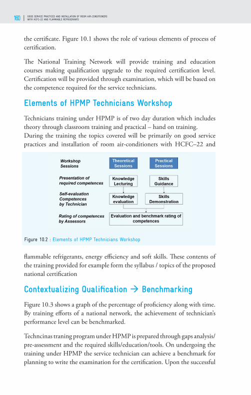
GOOD SERVICE PRACTICES AND INSTALLATION OF ROOM AIR-CONDITIONERS WITH HCFC–22 AND FLAMMABLE REFRIGERANTS160
the certifi cate. Figure 10.1 shows the role of various elements of process of certifi cation.
Th e National Training Network will provide training and education courses making qualifi cation upgrade to the required certifi cation level. Certifi cation will be provided through examination, which will be based on the competence required for the service technicians.
Elements of HPMP Technicians Workshop
Technicians training under HPMP is of two day duration which includes theory through classroom training and practical – hand on training. During the training the topics covered will be primarily on good service practices and installation of room air-conditioners with HCFC–22 and
fl ammable refrigerants, energy effi ciency and soft skills. Th ese contents of the training provided for example form the syllabus / topics of the proposed national certifi cation
Contextualizing Qualifi cation Benchmarking
Figure 10.3 shows a graph of the percentage of profi ciency along with time. By training eff orts of a national network, the achievement of technician’s performance level can be benchmarked.
Techncinas traning program under HPMP is prepared through gaps analysis/pre-assessment and the required skills/education/tools. On undergoing the training under HPMP the service technician can achieve a benchmark for planning to write the examination for the certifi cation. Upon the successful
Figure 10.2 : Elements of HPMP Technicians Workshop

TECHNICIANS HANDBOOK 161
Figure 10.3 : Contextualizing Qualifi cation- Benchmarking
completion of the certifi cation exam, technician can be registered as a nationally certifi ed technician for servicing room air-conditioner.
International Scenario
Many countries have a certifi cation system for room air-conditioner service technician and it is mandatory to have for installation and servicing of room ACs.
In the USA Environmental Protection Agency (EPA) gives a certifi cate to qualifi ed service technicians. It is a mandatory requirement of Refrigeration and air-conditioning technicians to pass an EPA approved test implemented by an approved certifying organization.
In European Union, the technicians are required to follow regulation ‘EN 13313 Competence of Personnel and EU “F-Gas” Regulation No 517/2014’. According to the EN 13313, persons responsible for installation, inspection, testing, maintenance, repair, commissioning, and disposal of air-conditioning systems and their parts, must have the competencies to be certifi ed by an approved national organization. Th e “F-gas” Regulation requires all personnel and companies to have a certifi cation proving their ability to manipulate systems using “F-gases”. Th e personnel certifi cation is obtained after a theoretical and practical assessment (EC No 303 & 304/2008 for examination requirements).
Japan has a certifi cation body - High-Pressure Gas Safety Act and the Refrigeration Safety Regulations. It is a mandatory requirement of Refrigeration and air-conditioning technicians to hold a Refrigeration Safety Manager Certifi cate.

GOOD SERVICE PRACTICES AND INSTALLATION OF ROOM AIR-CONDITIONERS WITH HCFC–22 AND FLAMMABLE REFRIGERANTS162
Ministry of Human Resources and Social Security (MHRSS), Australian Government give certifi cate III in Air-conditioning and Refrigeration to perform servicing work. In China Ministry of Human Resources and Social Security (MHRSS) gives certifi cation systems for refrigerant servicing technicians.
Certifi cation – Roles and Responsibility
Th e roles and responsibility of certifi cation system in India are as follows:
Certifi cation Standards is one standard framework across the nation as per National Skills Qualifi cation Framework (NSQF) Standard. Th e technicians must be qualifi ed as per Qualifi cation Packs (QPs) & National Occupational Standards (NOSs). An NSQF Certifi cation with Skill India logo is provided to the certifi ed technicians.
NOSs – National Occupational Standards (NOSs) specify the standard of performance, knowledge, and understanding when carrying out a particular activity in the workplace. Each NOS defi nes one key function in a job role.
QPs – A set of NOSs, aligned to a job role, called Qualifi cation Packs (QPs), would be available for every job role in each industry sector. Th is drive both the creation of curriculum, and assessments.
Th e affi liations of certifi cation are::• Adjoined industry and Govt certifi cate e.g. (ESSCI)• Training Partner (TP) & Trainer
Figure 10.4 : International Scenario
TECHNICIANS HANDBOOK 163
• Assessment Partner (AP) & Assessor• Master Trainer
Preparation for Exam
Training material prepared under HPMP for RAC technicians viz. the Technicians Handbook - Good Practices in Installation and Servicing of Room Air-conditioners with HCFC – 22 and fl ammable refrigerants (technicians receive it as reference material on undergoing the technicians training programs – HPMP Stage –II).
Participant Handbook – Field Technical Air Conditioner, published by ESSCI and some other relevant reading/reference material prepared by experts from RAC Industry Experts and other experts.
Follow “Qualifi cations Pack- Field Technician: Air Conditioner” Published by ESSCI, Skill India for Electronics. Participants must go through the Qualifi cation Pack that consists of the following topics:• Installation of room air conditioner• Repair of the dysfunctional air conditioner• Interaction with colleagues• Maintaining of health and safety • Engagement with the customer for service
Technicians can also refer E-learning contents in the student section of ESSCI website, www.essc-india.org
Examination and Assessment
Th e examination process involves following elements:i. Assessment and certifi cation is done as per the National Skills
Qualifi cations Framework (NSQF). Th is is a competency-based framework that organizes all qualifi cations according to a series of levels of knowledge, skills and aptitude.
ii. Assessment is by third party assessors who are affi liated with ESSCI on all of the National Occupational Standards (currently there are 4 for AC technicians).
iii. Written part of the assessment is done online at computer terminals (questions are selected from a common knowledge bank and are of

GOOD SERVICE PRACTICES AND INSTALLATION OF ROOM AIR-CONDITIONERS WITH HCFC–22 AND FLAMMABLE REFRIGERANTS164
varying levels of diffi culty).iv. Practical assessment which would include viva questions as well as
demonstration of skills is done by the assessment agency’s assessors. v. Grading and weightage of the various skills is as per the Qualifi cation
Pack published by ESSCI for various trades including RAC Field Technicians: Room ACs
vi. Th e technician should score a minimum of 70% of aggregate marks to successfully clear the assessment.
Certifi cate Sample

TECHNICIANS HANDBOOK 165

GOOD SERVICE PRACTICES AND INSTALLATION OF ROOM AIR-CONDITIONERS WITH HCFC–22 AND FLAMMABLE REFRIGERANTS166

TECHNICIANS HANDBOOK 167

GOOD SERVICE PRACTICES AND INSTALLATION OF ROOM AIR-CONDITIONERS WITH HCFC–22 AND FLAMMABLE REFRIGERANTS168
HCFC Phase-Out Management Plan (HPMP) for Service Sector in India: The Government of India has planned to reduce consumption of HCFC in the servicing sector during Phase 1 (2012 – 2014) in order to meet its compliance targets in 2013 (freeze) and 2015 (10% reduction) in line with the accelerated phase-out schedule of the Montreal Protocol. In the
servicing sector HCFC-123, HCFC-124, HCFC-142b and HCFC-22 are consumed, however, during Phase I only the consumption of HCFC-22 will be addressed. Awareness raising, early adoption of better servicing practices and recovery would have an immediate phase-out impact and could signifi cantly reduce the consumption of HCFC in the country
The Refrigeration and Air Conditioning (RAC) servicing sector contributes to a large extent to the consumption of HCFCs, in particular in the room air-conditioner segment. GIZ-Proklima on behalf of the Government of Germany and in close co-operation with the Ozone Cell in the Ministry of Environment and Forests will implement phase-out activities in the Indian RAC servicing sector. The consumption will be reduced mainly through training on better servicing practices and leak prevention but service technicians also need to be prepared on the introduction of alternatives like HC-290, HFC-410a and HFC-32. There are already 15 training partners in the country which will reach out to train as many technicians as possible and to address all the identifi ed sub-sectors in metros and towns all over India.
Lead Implementing Agency for Service Sector:Deutsche Gesellschaft für Internationale Zusammenarbeit (GIZ) GmbH B-5/2, Safdarjung Enclave New Delhi - 110029, IndiaTel: +91-11-49495353Web: www.giz.de/india