Discussion Managing People Managing Performance Good Practice Guide
Upload
hoangkhanhCategory
view
223download
0
PV LARGE-SCALE BUILDING INTEGRATED FIELD TRIALS
GOOD PRACTICE GUIDE ‘Managing Installation of PV Systems’
Contract Number: S/P2/00457
URN Number: 08/573
DTI Good Practice Guide - Managing Installation of Large PV Systems
1
PV LARGE-SCALE BUILDING INTEGRATED FIELD TRIAL
GOOD PRACTICE GUIDE
‘Managing Installation of PV Systems’
- for building owners and developers contemplating/installing a large PV system
Contract Number: S/P2/00457
URN Number: 08/573
Contractor Halcrow Group Ltd
Subcontractors
Cambridge Architectural Research Ltd White Consulting
Prepared by Emily Rudkin
Jim Thornycroft
First Published 2008 ©Crown Copyright 2008
The work described in this report was carried out under contract as part of the BERR New and Renewable Energy Programme, which is managed by AEA Energy & Environment. The views and judgements expressed in this report are those of the contractor and do not necessarily reflect those of BERR or by AEA Energy & Environment
DTI Good Practice Guide - Managing Installation of Large PV Systems
2
Table of Contents 1. Introduction ............................................................................................................................ 3
1.1 Purpose of guide .............................................................................................................. 3 1.2 DTI Large Scale Building Integrated Photovoltaic (LSBIPV) Programme.......................... 3 1.3 Definition of a Larger System............................................................................................ 4 1.4 Typical Project Cycle ........................................................................................................ 4
2. Organisation........................................................................................................................... 5 2.1 Who to involve in a project................................................................................................ 5 2.2 How many contracts / how to cover all responsibilities...................................................... 6 2.3 Tendering ......................................................................................................................... 6 2.4 Checking interface between contracts .............................................................................. 6 2.5 Other interfaces ................................................................................................................ 7
3. Design stage .......................................................................................................................... 8 3.1 Module Choice/ Mounting Options.................................................................................... 8 3.2 Module Technology Comparison Table........................................................................... 10 3.3 Building Aesthetics ......................................................................................................... 11 3.4 Electrical Wiring/Installation ............................................................................................ 11 3.5 Other energy efficiency measures .................................................................................. 11
4. Procurement......................................................................................................................... 12 4.1 Key Documents for PV ................................................................................................... 12 4.2 Communicating special requirements for PV to other trades........................................... 12 4.3 Checking Procurement Interfaces................................................................................... 13 4.4 Storage on site ............................................................................................................... 13 4.5 Warranties ...................................................................................................................... 13
5. Installation ............................................................................................................................ 14 5.1 Buildability / Project timings ............................................................................................ 14 5.2 Construction sequence ................................................................................................... 14 5.3 Liaisons required (DNO, roofer, PV specialist, main contractor etc)................................ 14
6. Commissioning of system..................................................................................................... 16 6.1 Interface to Electricity Network – permission to connect, metering.................................. 16 6.2 Commissioning of monitoring equipment ........................................................................ 16 6.3 Documentation and handover of PV system ................................................................... 17
7. Operation & maintenance..................................................................................................... 18 7.1 System Performance / Shading ...................................................................................... 18 7.2 Auto-reclose G59/1 relays .............................................................................................. 18 7.3 Identification of system failures....................................................................................... 18 7.4 Training in energy efficient behaviour ............................................................................. 19
Appendix 1 ............................................................................................................................... 20 Example table of 12 projects from the LSBIPV Programme.................................................. 20
Appendix 2 ............................................................................................................................... 22 Table of Key Documents for PV............................................................................................ 22
Appendix 3 ............................................................................................................................... 27 Monitoring of your PV system............................................................................................... 27
DTI Good Practice Guide - Managing Installation of Large PV Systems
3
How to set up the contracts, and questions to ask
• Posing the questions which a building owner should ask of a PV specialist, but without duplicating the detail of the specialist knowledge of a PV Specialist
• Focussing on the interfaces between the parties involved and the activities involved which the building owner should be aware of in overseeing and setting up the project
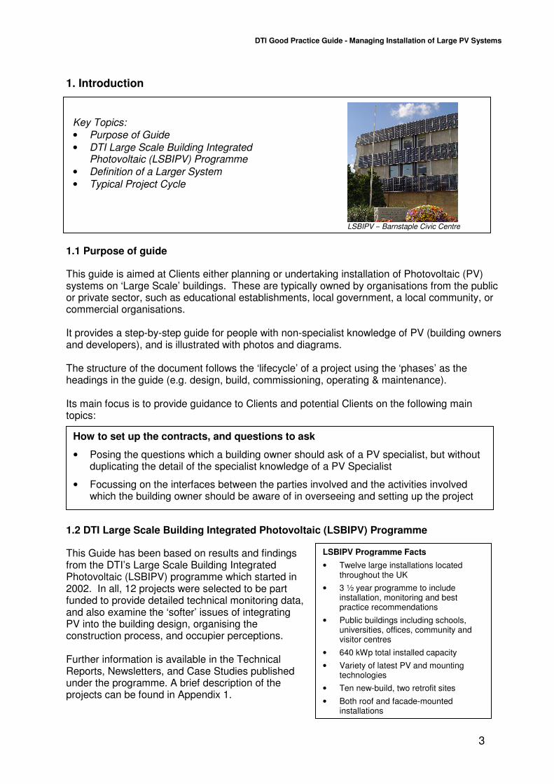
Key Topics:
• Purpose of Guide
• DTI Large Scale Building Integrated Photovoltaic (LSBIPV) Programme
• Definition of a Larger System
• Typical Project Cycle
LSBIPV Programme Facts
• Twelve large installations located throughout the UK
• 3 ½ year programme to include installation, monitoring and best practice recommendations
• Public buildings including schools, universities, offices, community and visitor centres
• 640 kWp total installed capacity
• Variety of latest PV and mounting technologies
• Ten new-build, two retrofit sites
• Both roof and facade-mounted installations
1. Introduction
1.1 Purpose of guide
This guide is aimed at Clients either planning or undertaking installation of Photovoltaic (PV) systems on ‘Large Scale’ buildings. These are typically owned by organisations from the public or private sector, such as educational establishments, local government, a local community, or commercial organisations. It provides a step-by-step guide for people with non-specialist knowledge of PV (building owners and developers), and is illustrated with photos and diagrams. The structure of the document follows the ‘lifecycle’ of a project using the ‘phases’ as the headings in the guide (e.g. design, build, commissioning, operating & maintenance). Its main focus is to provide guidance to Clients and potential Clients on the following main topics:
1.2 DTI Large Scale Building Integrated Photovoltaic (LSBIPV) Programme
This Guide has been based on results and findings from the DTI’s Large Scale Building Integrated Photovoltaic (LSBIPV) programme which started in 2002. In all, 12 projects were selected to be part funded to provide detailed technical monitoring data, and also examine the ‘softer’ issues of integrating PV into the building design, organising the construction process, and occupier perceptions. Further information is available in the Technical Reports, Newsletters, and Case Studies published under the programme. A brief description of the projects can be found in Appendix 1.
LSBIPV – Barnstaple Civic Centre
DTI Good Practice Guide - Managing Installation of Large PV Systems
4
Outline Design
Planning Permission
Detail Design
Building Construction (new build)
PV Install
PV Commission
Interface PV to Electricity Company
PV Operation &
Maintenance
PV Specialist
1.3 Definition of a Larger System The type of building suitable for a large scale PV system would typically have a south-facing roof or façade area sufficient to site from 200m2 to 1500m2 of PV. This would correspond to an installed ‘Watts Peak’ of 20 to 100kWp depending on what PV technology is used (see section 3 for technical information). Large scale PV differs from small ‘domestic’ systems in the way the projects are organised, in that they are typically owned and operated by organisations and groups rather than individual homeowners. This leads to different and potentially more complicated contractual arrangements as detailed in section 2. From the technical viewpoint, there is a wider range of options for mounting the PV compared to small PV systems, with the buildings typically having the option to mount glass/glass see-through glazing as well as integrated and ‘semi-integrated’ systems. These are covered in more detail in section 3. A further technical difference is the requirement for contacting the Electricity Company (Distribution Network Operator, DNO) for permission to connect in parallel with the conventional supply which changes when above a certain installed size (see section 6). A companion guide to this for smaller domestic systems is available from the DTI.
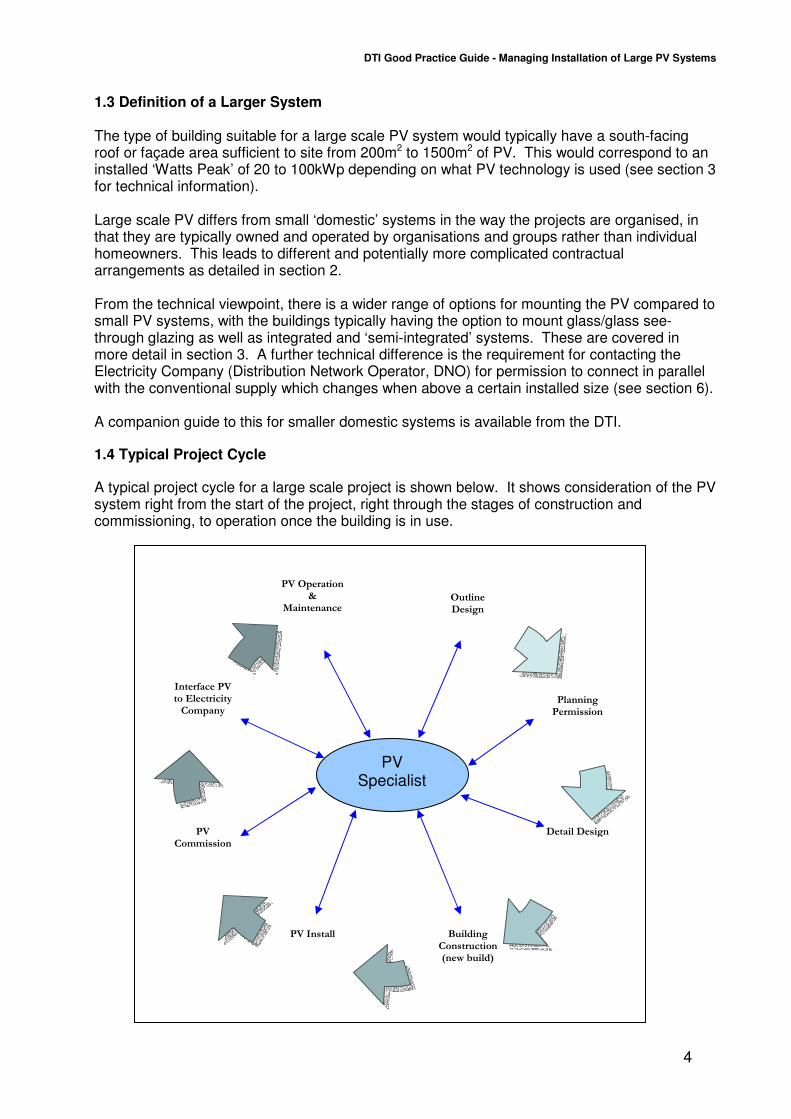
1.4 Typical Project Cycle
A typical project cycle for a large scale project is shown below. It shows consideration of the PV system right from the start of the project, right through the stages of construction and commissioning, to operation once the building is in use.
DTI Good Practice Guide - Managing Installation of Large PV Systems
5
‘Client’ (Building ‘Client’ (Building
A) ‘Client’ (Building Owner)
B) Design Consultant/ Architect
D) Main Contractor for building
C) PV specialist (PV Supply & DC installation)
E) Roofing Contractor
F) AC wiring contractor
Distribution Network Operator DNO (Connection)
Electricity Supplier (Tariffs & ROCs)
Building Control (Planning permission)
2. Organisation
2.1 Who to involve in a project
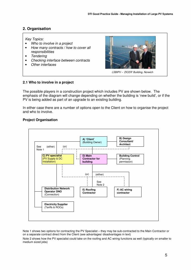
The possible players in a construction project which includes PV are shown below. The emphasis of the diagram will change depending on whether the building is ‘new build’, or if the PV is being added as part of an upgrade to an existing building. In either case there are a number of options open to the Client on how to organise the project and who to involve. Project Organisation
Note 1 shows two options for contracting the PV Specialist – they may be sub-contracted to the Main Contractor or on a separate contract direct from the Client (see advantages/ disadvantages in text)
Note 2 shows how the PV specialist could take on the roofing and AC wiring functions as well (typically on smaller to medium sized jobs)
(either)
(either) (or)
(or)
Key Topics:
• Who to involve in a project
• How many contracts / how to cover all responsibilities
• Tendering
• Checking interface between contracts
• Other interfaces
See Note 1
See Note 2
LSBIPV – ‘ZICER’ Building, Norwich

DTI Good Practice Guide - Managing Installation of Large PV Systems
6
2.2 How many contracts / how to cover all responsibilities
The Client (A), typically the building owner, shown at the top of the diagram would probably engage the services of a Design Consultant or Architect (B), especially if the project involved other work as well as the PV system. At this early stage, PV Specialists (C) should be asked to look at the project and suggest how their products could be most effectively incorporated into the building, and produce outline estimates and technical details. Alternatively, Design Consultants who have been involved in such schemes before, are increasingly gaining enough specialist knowledge to produce an outline scheme and cost themselves. To make sure the project is offered the full range of PV technology currently available as well as competitive prices it is recommended that several PV Specialists are contacted, as some might restrict themselves to particular products ranges that they are agents for.
2.3 Tendering
The main choice is then whether to let a separate contract direct with the PV Specialist, or incorporate the PV system as part of the scope of the main contractor. If there is limited other building work, the contract might be let direct from the Client to the PV Specialist. However, it would be more normal for a larger scale project to link the work of the main contractor and the PV Specialist by writing in a ‘liaison role’ between the two. Quite often this might involve the AC wiring and roofing being physically carried out by the main contractor (or their subcontractors), but to a specification and perhaps after training (e.g. for fitting PV roof tiles) given by the PV Specialist. The other main option is to require that the main contractor tender for the work as part of their contract and be fully responsible for any interfaces that there might be. This could either be by the design consultant providing a more detailed Tender Specification for the procurement and installation, or more normally at the moment, by choosing a scheme from a specific PV Specialist and then using them as a ‘Nominated Subcontractor’ for the works. The disadvantage to the Client of doing this might be a ‘handling charge’ from the main contractor for taking the responsibility for this additional work in his programme. With most projects currently being procured under the Government’s grants schemes, initial application for the grant is undertaken jointly between the Client and a chosen PV Specialist. However, some organisations (e.g. public bodies) will then be required to tender for the work against their internal procurement rules once the grant award has been authorised. If this is undertaken and the contract subsequently awarded to a second PV Specialist, occasionally, if a significant amount of work has been undertaken at the preparation stage, the first PV Specialist may require that this cost is refunded. It is also worth noting that the PV Specialist should be on an ‘approved’ list maintained under the scheme or by industry, to give added protection to the Client. A list of accredited solar PV installers under the grant schemes is available on the Energy Saving Trust website www.est.org.uk.
2.4 Checking interface between contracts
Interfaces between contracts are almost as key to the success of a scheme, as having the correct technical design in the first place. Whilst separating the contracts in both time and liability by completing the building first and then installing the PV as a ‘retrofit’ would provide a solution, in practice it is normally not the most efficient method, as potential savings both in the end-date and lack of duplicated work can be made by a well planned integrated scheme.
DTI Good Practice Guide - Managing Installation of Large PV Systems
7
Installing the PV as part of the fabric of the building (glass/glass façade or integrated ‘PV tiles’) is often best carried out by the ‘roofers’ with training and testing of the PV during installation carried out by the PV Specialist. Liability for any faults in building weather-proofness would have to be agreed in advance. The responsibility for carrying out a structural assessment of the building and support structure to prove it is strong enough to carry the additional weight and wind load from the PV is also a very important interface. On a new build, the design consultant is probably best placed to have the information to do the study for the building, with the PV Specialist providing the structural calculations for any framework they may install. However, information on component masses/sizes etc will have to be communicated between the two. The AC wiring is also often most efficiently installed at the same time as the building’s main electrical wiring. Again responsibility for installing the correct cable and providing the certification for it needs to be agreed in advance. Where the PV is to be installed by the PV Specialist themselves, it is important to ensure that any mounting feet/points are planned with the main roofers, so that the integrity of the roofing (and liability issues) is not compromised by adding the PV. The final main point on interfaces is to ensure that all works are accounted for in one of the contracts, and that there are not any unwanted surprises on reaching a late stage of the installation.
2.5 Other interfaces
To ensure there is no delay in waiting for permission from planning authorities, or for connection of the system to the electricity supply, it is important for the Client to be clear what is required, and to ensure that a member of the team is responsible for each aspect. Typically the Design Consultant would inform the Client of planning permission requirements, and seek these on their behalf. However, if the PV was in a prominent position or mounted away from the normal building fabric, the PV Specialist would probably need to provide additional details to support the application for planning permission. For connection to the Distribution Network Operator’s (DNO) system, the PV Specialist would usually make the Client aware of requirements. However the final Agreements are usually signed between the Client and the DNO. Tariffs, ROCs (Renewable Obligation Certificates), and installation of an ‘export meter’ are again commercial arrangements between the Client and an Electricity Supplier. Although the PV Specialist can usually provide links to further information, it is usually the Client who progresses this, as similar to Supply contracts it is usual for these to be changed over the lifetime of the system.
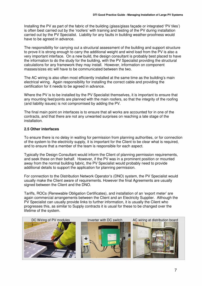
DC Wiring of PV modules Inverter with DC switch AC wiring at distribution board
DTI Good Practice Guide - Managing Installation of Large PV Systems
8
3. Design stage
3.1 Module Choice/ Mounting Options
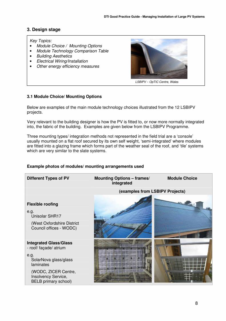
Below are examples of the main module technology choices illustrated from the 12 LSBIPV projects. Very relevant to the building designer is how the PV is fitted to, or now more normally integrated into, the fabric of the building. Examples are given below from the LSBIPV Programme. Three mounting types/ integration methods not represented in the field trial are a ‘console’ usually mounted on a flat roof secured by its own self weight, ‘semi-integrated’ where modules are fitted into a glazing frame which forms part of the weather seal of the roof, and ‘tile’ systems which are very similar to the slate systems.
Example photos of modules/ mounting arrangements used
Different Types of PV
Mounting Options – frames/ integrated
Module Choice
(examples from LSBIPV Projects)
Flexible roofing
e.g. Unisolar SHR17
(West Oxfordshire District Council offices - WODC)
Integrated Glass/Glass - roof/ façade/ atrium
e.g. SolarNova glass/glass laminates
(WODC, ZICER Centre, Insolvency Service, BELB primary school)
Key Topics:
• Module Choice / Mounting Options
• Module Technology Comparison Table
• Building Aesthetics
• Electrical Wiring/Installation
• Other energy efficiency measures
LSBIPV – OpTIC Centre, Wales

DTI Good Practice Guide - Managing Installation of Large PV Systems
9
Slate
e.g. Atlantis Sunslates (Columba Centre)
Bolt on - Crystalline (over roof)
e.g.
• BP585 (Cotswold Water Park)
• BP2150F (Gaia Energy Centre)
• BP5170 (St Mary’s Church)
• Photowatt PW1650 (University of Gloucestershire)
• BP5170 (Barnstaple Civic Centre)
Bolt on -Thin Film
e.g.
• Kaneka LS202 (Birmingham High Performance Centre)
• Shell ST36 Copper-Indium-Diselenide (OpTIC Centre)
Tile (Not used on LFT) Similar to ‘slate’ but often in wider strips.
Semi-integrated (Not used on LFT) Standard modules but put into roof so that they provide part of the roof weatherproof skin.
Console (Not used on LFT) Free-standing, weighted by ballast
DTI Good Practice Guide - Managing Installation of Large PV Systems
10
3.2 Module Technology Comparison Table
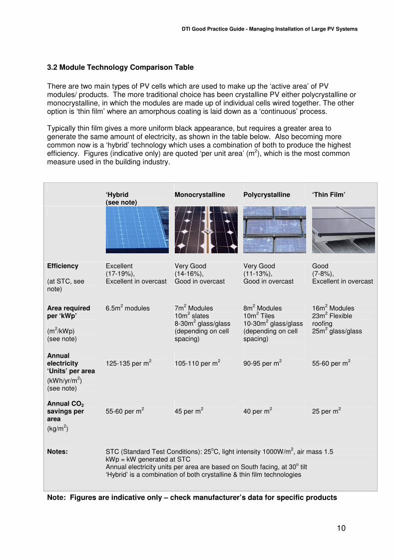
There are two main types of PV cells which are used to make up the ‘active area’ of PV modules/ products. The more traditional choice has been crystalline PV either polycrystalline or monocrystalline, in which the modules are made up of individual cells wired together. The other option is ‘thin film’ where an amorphous coating is laid down as a ‘continuous’ process. Typically thin film gives a more uniform black appearance, but requires a greater area to generate the same amount of electricity, as shown in the table below. Also becoming more common now is a ‘hybrid’ technology which uses a combination of both to produce the highest efficiency. Figures (indicative only) are quoted ‘per unit area’ (m2), which is the most common measure used in the building industry.
‘Hybrid (see note)
Monocrystalline Polycrystalline ‘Thin Film’
Efficiency (at STC, see note)
Excellent (17-19%), Excellent in overcast
Very Good (14-16%), Good in overcast
Very Good (11-13%), Good in overcast
Good (7-8%), Excellent in overcast
Area required per ‘kWp’ (m
2/kWp)
(see note)
6.5m2 modules 7m
2 Modules
10m2 slates
8-30m2 glass/glass
(depending on cell spacing)
8m2 Modules
10m2 Tiles
10-30m2 glass/glass
(depending on cell spacing)
16m2 Modules
23m2 Flexible
roofing 25m
2 glass/glass
Annual electricity ‘Units’ per area
(kWh/yr/m2)
(see note)
125-135 per m
2
105-110 per m
2
90-95 per m
2
55-60 per m
2
Annual CO2
savings per area
(kg/m2)
55-60 per m
2
45 per m
2
40 per m
2
25 per m
2
Notes: STC (Standard Test Conditions): 25oC, light intensity 1000W/m
2, air mass 1.5
kWp = kW generated at STC Annual electricity units per area are based on South facing, at 30
o tilt
‘Hybrid’ is a combination of both crystalline & thin film technologies
Note: Figures are indicative only – check manufacturer’s data for specific products
DTI Good Practice Guide - Managing Installation of Large PV Systems
11
3.3 Building Aesthetics
The type of module chosen and its mounting system will have a considerable effect on the aesthetics of the building. In well chosen combinations which compliment the style and materials of the building the aesthetics are often enhanced, as well as giving the building a high tech and environmental image. Appendix 1 shows photographs of the results achieved on the buildings within the LBIPV Programme, using a range of products available at the time of building.
3.4 Electrical Wiring/Installation
Electrical installation is covered in some detail in the PV Installation Guide presented in Section 4 of this guide. Important points for Clients to be aware of are that the installation on the module side of the inverters is ‘DC’ which is not always commonly used by electricians in their normal work. In addition, because of special ‘current limiting’ properties of PV cells, these circuits cannot be protected against faults by normal fuses in the same way that standard power circuits are, and so again special measures are taken as described in the Guide and advised by the PV specialist. The ‘inverter’ provides an interface to the normal electricity supply in the building, with the output being ‘AC’ allowing the system to operate in parallel with the other generators and loads on the system. Part of the requirements for connection in parallel is a protection relay (‘G59/1’ for bigger systems) or inverters which incorporate a similar function (‘G83/1 tested’) for smaller systems. At the present time there are about half a dozen manufacturers with products ‘type tested’ to the G83/1 requirements. The AC wiring is essentially the same as used for other building systems and if feasible should be installed by the contractor during the other work on the building.
3.5 Other energy efficiency measures
PV is only one of a number of measures that can be designed into a building to reduce its energy use and CO2 emissions. PV should be complemented with other energy efficiency measures such as insulation to reduce heat loss from the building envelope, energy efficient technology, and perhaps other renewable energy technologies. Passive solar design can also significantly reduce the energy demands of a building. New larger scale buildings are likely to be designed to the BREEAM ratings on energy efficiency, which usually exceed Building Regulation requirements.

DTI Good Practice Guide - Managing Installation of Large PV Systems
12
Key Topics:
• Key documents for PV
• Communicating special requirements for PV to other trades
• Checking Procurement Interfaces
• Storage on site
• Warranties
4. Procurement
4.1 Key Documents for PV
Key documents to be aware of are shown in the table in Appendix 2. It would be useful for the Client to be aware of the existence of the documents and to check that the system is being designed and installed using their guidance and requirements, but it would not be necessary to read them in depth:
4.2 Communicating special requirements for PV to other trades
The documents in Appendix 2 can be used to specify the particular requirements to other trades.
The ‘Photovoltaics in Buildings - Guide to the installation of PV systems, 2nd edition’ is the main ‘best practice guide for PV, with references to many of the documents in the Appendix
‘Engineering Recommendation G59/1’ is the Electricity Industry Recommendation for connection of large generators.
LSBIPV – Columba Centre, Islay
DTI Good Practice Guide - Managing Installation of Large PV Systems
13
For instance, the DC requirements for PV are summarised in the first document, the PV Installers Guide. Also, if electricians for the AC side of the system need guidance on specification of equipment or labelling, again this can be found in the PV Installers Guide. Electrical interface requirements are detailed in full in the Engineering Recommendations.
4.3 Checking Procurement Interfaces
As well as the electrical installation interfaces, interfaces with the roofing will need to be made. For roofers procuring material for the roof or façade installation, the PV Specialist should make available the brochures and manuals for the PV system to be used, and communicate any dimensional requirements so that these can be planned from the procurement stage. This will reduce the risk of delays in the installation phase by ensuring that all components are ready and dimensioned correctly.
4.4 Storage on site
If the PV modules are procured by the PV Specialist, then arrangements should be made for the material to be stored safely, and also for the relevant insurances to be in place.
4.5 Warranties
In addition, it should be decided in advance where the interfaces are for the warranty on the system. From the Client’s point of view, a single warranty from the main contractor is the easiest to manage, but if installed as separate contracts warranties should detail the extent of each responsibility. This could be complex in an area like a roof leak, where the PV Specialist might have specified the work and provided the PV material, but the roofer installed it. It would need to be established if the fault were with the specification, or the quality of installation. It is usual for extended warranties on equipment such as PV modules to be passed on to the owner. As described in Section 6.3, during the initial period where there is a guarantee of workmanship it is usual to pass any warranty issues through the PV Specialist.
DTI Good Practice Guide - Managing Installation of Large PV Systems
14
5. Installation
5.1 Buildability / Project timings
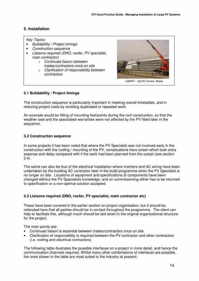
The construction sequence is particularly important in meeting overall timetables, and in reducing project costs by avoiding duplicated or repeated work. An example would be fitting of mounting feet/points during the roof construction, so that the weather seal and the associated warranties were not affected by the PV fitted later in the sequence.
5.2 Construction sequence
In some projects it has been noted that where the PV Specialist was not involved early in the construction with the roofing / mounting of the PV, complications have arisen which took extra expense and delay compared with if the work had been planned from the outset (see section 2.4). The same can also be true of the electrical installation where inverters and AC wiring have been undertaken by the building AC contractor later in the build programme when the PV Specialist is no longer on site. Locations of equipment and specifications of components have been changed without the PV Specialists knowledge, and on commissioning either has to be returned to specification or a non-optimal solution accepted.
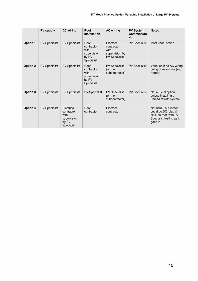
5.3 Liaisons required (DNO, roofer, PV specialist, main contractor etc)
These have been covered in the earlier section on project organisation, but it should be reiterated here that all parties should be in contact throughout the programme. The client can help to facilitate this, although much should be laid down in the original organisational structure for the project. The main points are:
• Continued liaison is essential between trades/contractors once on site
• Clarification of responsibility is required between the PV contractor and other contractors (i.e. roofing and electrical contractors)
The following table illustrates the possible interfaces on a project in more detail, and hence the communication channels required. Whilst many other combinations of interfaces are possible, the ones shown in the table are most suited to the industry at present:
Key Topics:
• Buildability / Project timings
• Construction sequence
• Liaisons required (DNO, roofer, PV specialist, main contractor)
o Continued liaison between trades/contractors once on site
o Clarification of responsibility between contractors
LSBIPV – OpTIC Centre, Wales
DTI Good Practice Guide - Managing Installation of Large PV Systems
15
PV supply DC wiring Roof installation
AC wiring PV System Commission-ing
Notes
Option 1 PV Specialist PV Specialist Roof contractor with supervision by PV Specialist
Electrical contractor with supervision by PV Specialist
PV Specialist Most usual option
Option 2 PV Specialist PV Specialist Roof contractor with supervision by PV Specialist
PV Specialist (or their subcontractor)
PV Specialist Variation if no AC wiring being done on site (e.g. retrofit)
Option 3 PV Specialist PV Specialist PV Specialist PV Specialist (or their subcontractor)
PV Specialist Not a usual option unless installing a framed retrofit system
Option 4 PV Specialist Electrical contractor with supervision by PV Specialist
Roof contractor
Electrical contractor
Not usual, but roofer could do DC ‘plug & skts’ on roof, with PV Specialist testing as it goes in
DTI Good Practice Guide - Managing Installation of Large PV Systems
16
Key Topics:
• Interface to Electricity Network – permission to connect, metering
• Commissioning of monitoring equipment
• Documentation and handover of PV system
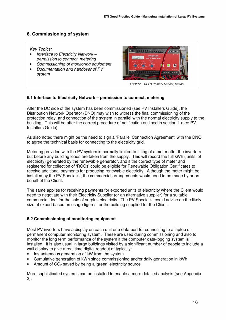
6. Commissioning of system
6.1 Interface to Electricity Network – permission to connect, metering
After the DC side of the system has been commissioned (see PV Installers Guide), the Distribution Network Operator (DNO) may wish to witness the final commissioning of the protection relay, and connection of the system in parallel with the normal electricity supply to the building. This will be after the correct procedure of notification outlined in section 1 (see PV Installers Guide). As also noted there might be the need to sign a ‘Parallel Connection Agreement’ with the DNO to agree the technical basis for connecting to the electricity grid. Metering provided with the PV system is normally limited to fitting of a meter after the inverters but before any building loads are taken from the supply. This will record the full kWh (‘units’ of electricity) generated by the renewable generator, and if the correct type of meter and registered for collection of ‘ROCs’ could be eligible for Renewable Obligation Certificates to receive additional payments for producing renewable electricity. Although the meter might be installed by the PV Specialist, the commercial arrangements would need to be made by or on behalf of the Client. The same applies for receiving payments for exported units of electricity where the Client would need to negotiate with their Electricity Supplier (or an alternative supplier) for a suitable commercial deal for the sale of surplus electricity. The PV Specialist could advise on the likely size of export based on usage figures for the building supplied for the Client.
6.2 Commissioning of monitoring equipment
Most PV inverters have a display on each unit or a data port for connecting to a laptop or permanent computer monitoring system. These are used during commissioning and also to monitor the long term performance of the system if the computer data-logging system is installed. It is also usual in large buildings visited by a significant number of people to include a wall display to give a real time digital readout of typically:
• Instantaneous generation of kW from the system
• Cumulative generation of kWh since commissioning and/or daily generation in kWh
• Amount of CO2 saved by being a ‘green’ electricity source More sophisticated systems can be installed to enable a more detailed analysis (see Appendix 3).
LSBIPV – BELB Primary School, Belfast
DTI Good Practice Guide - Managing Installation of Large PV Systems
17
6.3 Documentation and handover of PV system
When the work has been completed, the system should be fully checked and tested. Any test results will be recorded on a commissioning record (see PV Installers Guide), and this will be signed by an authorised signatory to confirm the work is satisfactory. When the work has been completed, the Client should be given a copy of this commissioning record together with relevant conformity certificates and guarantees. The Specialist will also give the Client full operating and maintenance instructions, along with a full description of the system. All the documents provided should be written in plain English. Handover documentation should also be accompanied by a Warranty for the system including equipment (usually comprising manufacturers warranties), and workmanship. It would be usual for the PV system to be warranted for a certain period through the one point of contact with the PV Specialist, so that any diagnostics and remedial work would be carried out by the Specialist as part of that Warranty. Although there is no agreed standard method of specifying it yet, it is recommended that the Client request some form of guarantee of performance from the Specialist. This is to ensure a guaranteed minimum output from their PV system (normally over a year). Most warranties only cover for failures of components in the PV system. However in the LSBIPV programme, there have been instances where parts of the Client’s system have underperformed without failure and this has not been covered under the Warranty. It is also recommended that the Client inform their insurance company that PV is mounted on the building, and check whether there are any additional requirements from their insurer.

DTI Good Practice Guide - Managing Installation of Large PV Systems
18
Key Topics:
• System Performance / Shading
• Auto-reclose G59/1 relays
• Identification of system failures
• Training in energy efficient behaviour
7. Operation & maintenance
7.1 System Performance / Shading
Some guidance on the performance of systems is given in the update of the PV Installers Guide in Section 4. The PV Specialist should model the system using one of the software simulation programmes available, which have a ‘library’ of modules and inverters and can select the sunlight conditions most representative of the site. If shading is seen to be a potential problem at the site, then its effect can be minimised, by using the PV simulation programme to ‘fine tune’ the design, or discount the use of part of the building if it is not suitable. Also, some types of PV operate better in more diffuse light (thin film or hybrid) and these panels might be selected in certain conditions – the PV Specialist should be able to advise on this.
7.2 Auto-reclose G59/1 relays
An example of problems encountered during operation in the LSBIPV programme is the tripping of the main G59/1 protection relay, by the mains operating out of limits. This is not usually apparent at commissioning and will cause the system to shut down. If a manual reset relay has been selected, this may go undetected for some time before the relay is reset and the output from the system used. If there are any concerns regarding the mains in the area, it is recommended that an automatic reset relay is installed.
7.3 Identification of system failures
Although PV operates largely without maintenance, all PV systems in the LSBIPV programme had partial failures during the monitoring period, such as the tripping of circuit breakers or the G59 relay. This demonstrates the importance of monitoring to identify problems, minimise downtime and get the highest energy output from the system. It is recommended that a person is assigned to monitoring the system, either by observing the displays/lights on the inverters themselves, by looking at the trend graphs if the system is monitored on computer, or by a remote data link if there is going to be no-one on site in a position to keep an eye on the system. This may be a member of staff or in larger buildings someone on the building management team. Alternatively for an additional fee, the PV Specialist may be able to remotely monitor the system, or recommend someone else to do this. It is also highly recommended that the location of the inverters is carefully considered during the design phase to ensure easy access for monitoring and carrying out of maintenance activities when necessary.
LSBIPV – Columba Centre, Islay
DTI Good Practice Guide - Managing Installation of Large PV Systems
19
7.4 Training in energy efficient behaviour
While a PV system can make a significant contribution to a building’s energy demand, in many cases the behaviour of the occupants in a building can have an even greater effect. Education of building occupants to ensure that basic energy conservation measures are employed is an essential component to ensure that the energy generated from the PV system is not wasted.
DTI Good Practice Guide - Managing Installation of Large PV Systems
20
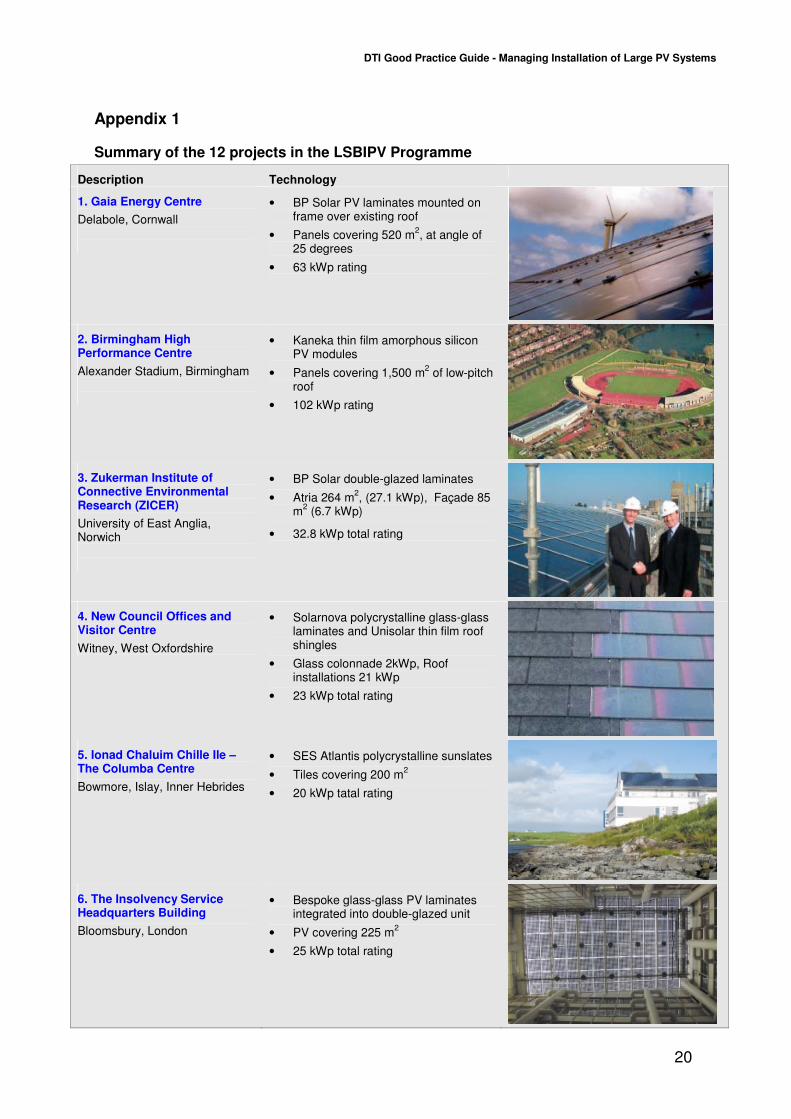
Appendix 1
Summary of the 12 projects in the LSBIPV Programme
Description Technology
1. Gaia Energy Centre
Delabole, Cornwall
• BP Solar PV laminates mounted on frame over existing roof
• Panels covering 520 m2, at angle of
25 degrees
• 63 kWp rating
2. Birmingham High Performance Centre
Alexander Stadium, Birmingham
• Kaneka thin film amorphous silicon PV modules
• Panels covering 1,500 m2 of low-pitch
roof
• 102 kWp rating
3. Zukerman Institute of Connective Environmental Research (ZICER)
University of East Anglia, Norwich
• BP Solar double-glazed laminates
• Atria 264 m2, (27.1 kWp), Façade 85
m2 (6.7 kWp)
• 32.8 kWp total rating
4. New Council Offices and Visitor Centre
Witney, West Oxfordshire
• Solarnova polycrystalline glass-glass laminates and Unisolar thin film roof shingles
• Glass colonnade 2kWp, Roof installations 21 kWp
• 23 kWp total rating
5. Ionad Chaluim Chille Ile – The Columba Centre
Bowmore, Islay, Inner Hebrides
• SES Atlantis polycrystalline sunslates
• Tiles covering 200 m2
• 20 kWp tatal rating
6. The Insolvency Service Headquarters Building
Bloomsbury, London
• Bespoke glass-glass PV laminates integrated into double-glazed unit
• PV covering 225 m2
• 25 kWp total rating
DTI Good Practice Guide - Managing Installation of Large PV Systems
21
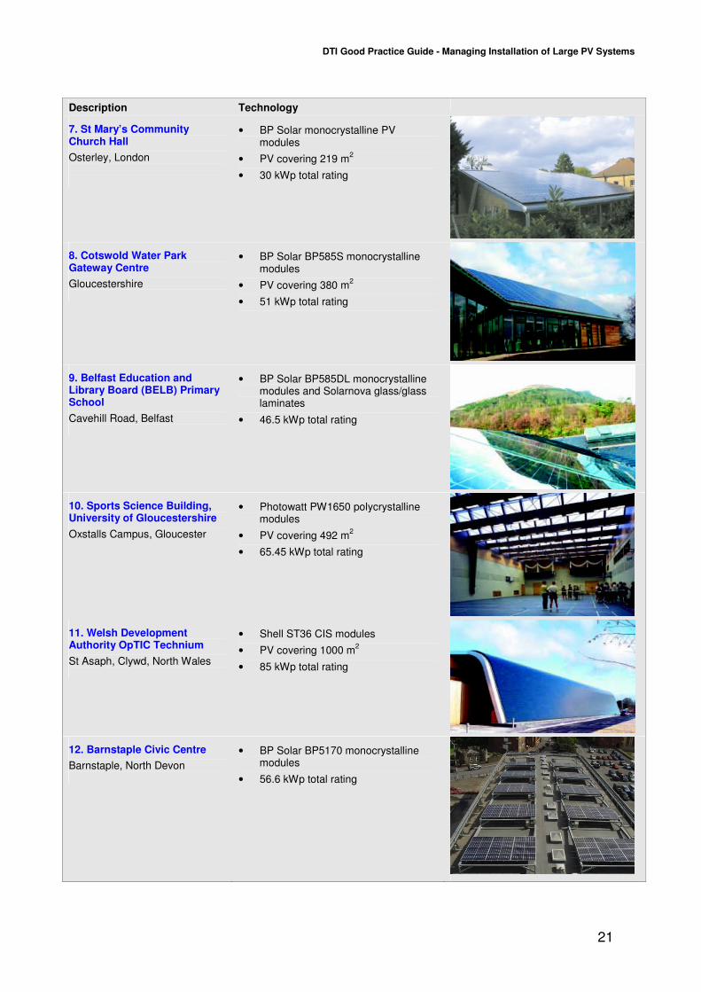
Description Technology
7. St Mary’s Community Church Hall
Osterley, London
• BP Solar monocrystalline PV modules
• PV covering 219 m2
• 30 kWp total rating
8. Cotswold Water Park Gateway Centre
Gloucestershire
• BP Solar BP585S monocrystalline modules
• PV covering 380 m2
• 51 kWp total rating
9. Belfast Education and Library Board (BELB) Primary School
Cavehill Road, Belfast
• BP Solar BP585DL monocrystalline modules and Solarnova glass/glass laminates
• 46.5 kWp total rating
10. Sports Science Building, University of Gloucestershire
Oxstalls Campus, Gloucester
• Photowatt PW1650 polycrystalline modules
• PV covering 492 m2
• 65.45 kWp total rating
11. Welsh Development Authority OpTIC Technium
St Asaph, Clywd, North Wales
• Shell ST36 CIS modules
• PV covering 1000 m2
• 85 kWp total rating
12. Barnstaple Civic Centre
Barnstaple, North Devon
• BP Solar BP5170 monocrystalline modules
• 56.6 kWp total rating

DTI Good Practice Guide - Managing Installation of Large PV Systems
22
Appendix 2
Table of Key Documents for PV
Title Front Cover Notes
Photovoltaics in Buildings Guide to the installation of PV systems 2
nd edition
The main ‘best practice guide for PV, with references to many of the documents below.
Engineering Recommendation G59/1 ‘Recommendations for the connection of Embedded Generating Plant to the Regional Electricity Companies’ Distribution Systems’, (Electricity Association, 1991), www.energynetworks.org/dg01.asp
Note: This is the Electricity Industry Recommendation for connection of generators. It is applicable if the inverter is not covered under G83/1. Other guidance can be found in IEC 61727 Ed.2: Photovoltaic (PV) systems - Characteristics of the utility interface.
Engineering Recommendation G83/1 Sept 2003, ‘Recommendations for the connection of Small-scale Embedded Generators (up to 16A per phase) in parallel with Public Low-Voltage Distribution Networks’, (Energy Networks Association, 2003), www.energynetworks.org/dg01.asp
Note: This simplified connection route applies to ‘type tested’ inverters for systems up to about 5kWp. Prior-notification of the Distribution Network Operator (DNO) is not required for ‘single’ installations, but is required for ‘multiple’ single phase installations.
It refers to the Electricity Safety, Quality and Continuity Regulations (ESQCR), 2002. Draft prEN 50438 ‘Requirements for the connection of micro-cogenerators in parallel with public low-voltage distribution networks’ is a European version, which once issued, will also cover systems up to 16A per phase.
DTI Good Practice Guide - Managing Installation of Large PV Systems
23
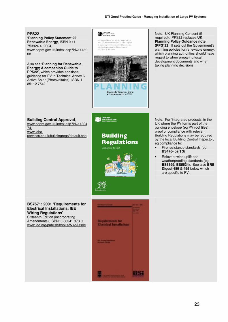
PPS22 ‘Planning Policy Statement 22: Renewable Energy, ISBN 0 11 753924 4, 2004, www.odpm.gov.uk/index.asp?id=1143908
Also see ‘Planning for Renewable Energy; A companion Guide to PPS22’, which provides additional guidance for PV in Technical Annex 6 Active Solar (Photovoltaics), ISBN 1 85112 7542.
Note: UK Planning Consent (if required). PPS22 replaces UK Planning Policy Guidance note (PPG)22. It sets out the Government's planning policies for renewable energy, which planning authorities should have regard to when preparing local development documents and when taking planning decisions.
Building Control Approval, www.odpm.gov.uk/index.asp?id=1130474, www.labc-services.co.uk/buildingregs/default.asp
Note: For ‘integrated products’ in the UK where the PV forms part of the building envelope (eg PV roof tiles), proof of compliance with relevant Building Regulations may be required by the local Building Control Inspector, eg compliance to:
• Fire resistance standards (eg BS476- part 3)
• Relevant wind uplift and weatherproofing standards (eg BS6399, BS5534). See also BRE Digest 489 & 495 below which are specific to PV.
BS7671: 2001 ‘Requirements for Electrical Installations, IEE Wiring Regulations’ Sixteenth Edition (incorporating Amendments), ISBN: 0 86341 373 0, www.iee.org/publish/books/WireAssoc
DTI Good Practice Guide - Managing Installation of Large PV Systems
24
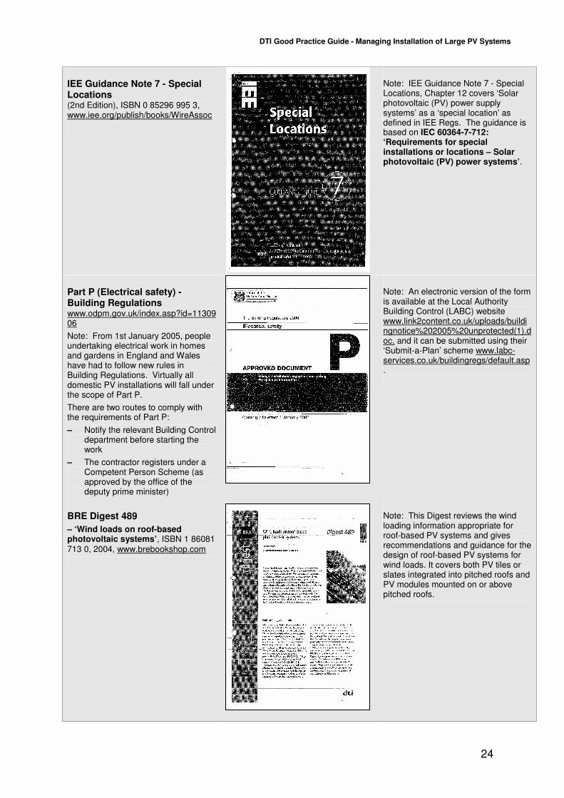
IEE Guidance Note 7 - Special Locations (2nd Edition), ISBN 0 85296 995 3, www.iee.org/publish/books/WireAssoc
Note: IEE Guidance Note 7 - Special Locations, Chapter 12 covers ‘Solar photovoltaic (PV) power supply systems’ as a ‘special location’ as defined in IEE Regs. The guidance is based on IEC 60364-7-712: ‘Requirements for special installations or locations – Solar photovoltaic (PV) power systems’.
Part P (Electrical safety) - Building Regulations www.odpm.gov.uk/index.asp?id=1130906
Note: From 1st January 2005, people undertaking electrical work in homes and gardens in England and Wales have had to follow new rules in Building Regulations. Virtually all domestic PV installations will fall under the scope of Part P.
There are two routes to comply with the requirements of Part P:
– Notify the relevant Building Control department before starting the work
– The contractor registers under a Competent Person Scheme (as approved by the office of the deputy prime minister)
Note: An electronic version of the form is available at the Local Authority Building Control (LABC) website www.link2content.co.uk/uploads/buildingnotice%202005%20unprotected(1).doc, and it can be submitted using their ‘Submit-a-Plan’ scheme www.labc-services.co.uk/buildingregs/default.asp.
BRE Digest 489
– ‘Wind loads on roof-based photovoltaic systems’, ISBN 1 86081 713 0, 2004, www.brebookshop.com
Note: This Digest reviews the wind loading information appropriate for roof-based PV systems and gives recommendations and guidance for the design of roof-based PV systems for wind loads. It covers both PV tiles or slates integrated into pitched roofs and PV modules mounted on or above pitched roofs.
DTI Good Practice Guide - Managing Installation of Large PV Systems
25
BRE Digest 495
Mechanical installation of roof-mounted photovoltaic systems
ISBN 1 86081 869 23, 2005, www.brebookshop.com
Note: This Digest gives guidance on installing and using photovoltaic systems on roofs. The guidance refers only to the mechanical installation of roof mounted integrated and stand-off photovoltaic systems; it provides best practice guidance on installation requirements and does not constitute fixing instructions.
‘Photovoltaics in Buildings– Safety and the CDM Regulations’
(BSRIA/DTI Feb 2000, ISBN 0 86022 548 8), www.bsria.co.uk/bookshop/system/index.html
This covers larger systems, although most of the safety advice is also relevant to small installations that may be exempt from the Regulations.
It provides a simple guide to the Construction Design and Management Regulations 1994 (CDM Regulations), with regard to the design, installation, operation, maintenance, decommissioning and disposal of PV installations in buildings.
Note: It also provides a commentary on the UK legislative framework with particular reference to CDM Regulations, hazards and risks associated with PV installations, and PV issues that must be addressed in the Health and Safety Plan and Health and Safety File.
Draft IEC 62446 Ed.1 ‘Grid connected PV systems – Minimum system documentation, commissioning tests and inspection requirements’.
Note: This standard will define the minimum information and documentation required to be handed over to a customer following the installation of a grid connected PV system. This document also describes the minimum commissioning tests, inspection criteria and documentation expected to verify the safe installation and correct operation of the system. This document is not written for AC module systems or systems that utilize energy storage (e.g. batteries) or hybrid systems.
DTI Good Practice Guide - Managing Installation of Large PV Systems
26
IEC 61215 ‘Crystalline silicon terrestrial photovoltaic (PV) modules – Design qualification and type approval’
www.iec.ch/cgi-in/procgi.pl/www/iecwww.p?wwwlang=e&wwwprog=TCpubs.p&progdb=db1&committee=TCTC&number=82
Note: This is the International standard for crystalline PV. It specifies requirements for the design qualification and type approval of terrestrial photovoltaic modules suitable for long-term operation in general open-air climates, as defined in IEC 60721-2-1. It determines the electrical and thermal characteristics of the module and shows, as far as possible, that the module is capable of withstanding prolonged exposure in certain climates.
IEC 61646 ‘Thin film terrestrial photovoltaic (PV) modules – Design qualification and type approval’
www.iec.ch/cgi-bin/procgi.pl/www/iecwww.p?wwwlang=e&wwwprog=TCpubs.p&progdb=db1&committee=TCTC&number=82
(In preparation - IEC 61646 Ed. 2.0 E 1CD Thin-film terrestrial photovoltaic (PV) modules - Design qualification and type approval)
Note: This is the International standard for thin film PV. It specifies requirements for the design qualification and type approval of terrestrial thin-film photovoltaic modules suitable for long-term operation in moderate open-air climates.
IEC 61730-1
IEC 61730-1 ‘Photovoltaic (PV) module safety qualification - Part 1: Requirements for construction
&
IEC 61730-2 ‘Photovoltaic (PV) module safety qualification - Part 2: Requirements for testing’,
www.iec.ch/cgi-bin/procgi.pl/www/iecwww.p?wwwlang=e&wwwprog=TCpubs.p&progdb=db1&committee=TCTC&number=82
Note: Part 1 is Fundamental construction requirements, Part 2 is Testing requirements. These two international standards specify requirements for photovoltaic modules in order to provide safe electrical and mechanical operation during their expected lifetime. They address the prevention of electrical shock, fire hazards, and personal injury due to mechanical and environmental stresses. Pertains to the particular requirements of construction and is to be used in conjunction with IEC 61215 or IEC 61646.
DTI Good Practice Guide - Managing Installation of Large PV Systems
27
Measured parameters:
• Solar radiation on the horizontal
• Solar radiation in plane of array
• Ambient temperature
• Array temperature
• DC electrical output of each PV array
• AC output of each inverter
• Electricity imported to the building
• Electricity exported from the building
Energy Output from PV System
0
2000
4000
6000
8000
10000
12000
Jan-0
5
Feb
-05
Mar
-05
Apr
-05
May
-05
Jun-0
5
Jul-05
Aug
-05
Sep
-05
Oct
-05
Nov-
05
Dec-
05
Outp
ut
kW
h
Actual output
Predicted output
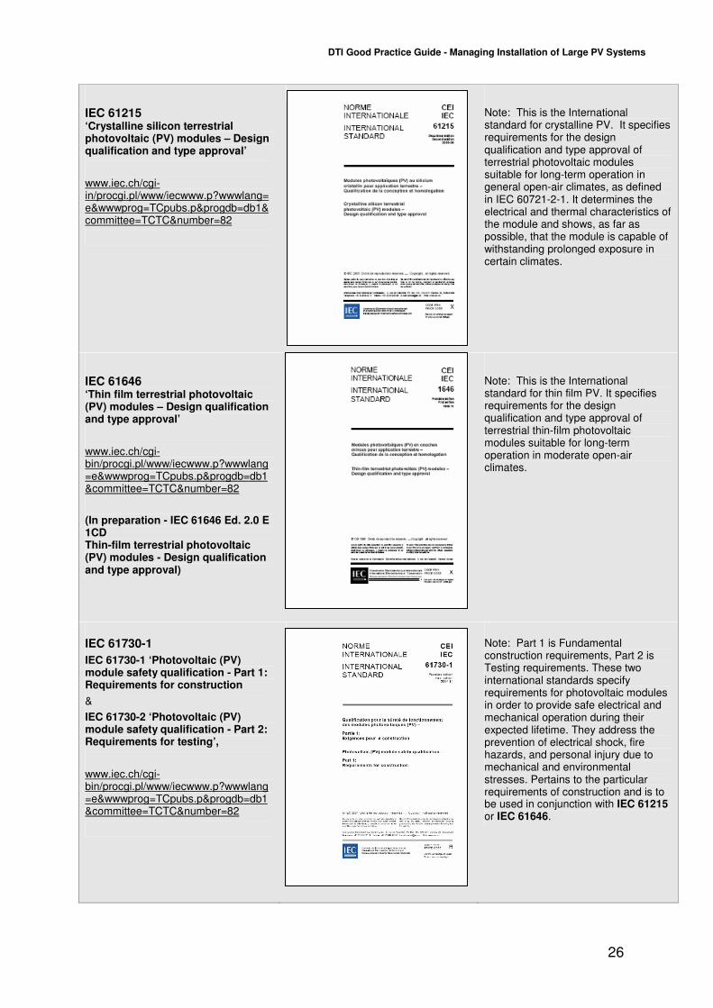
Example of annual processed data, comparing actual energy output with estimated output at the OpTIC Centre, North Wales
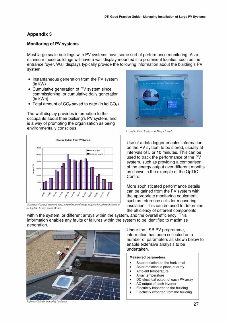
Reference Cells for measuring Insolation
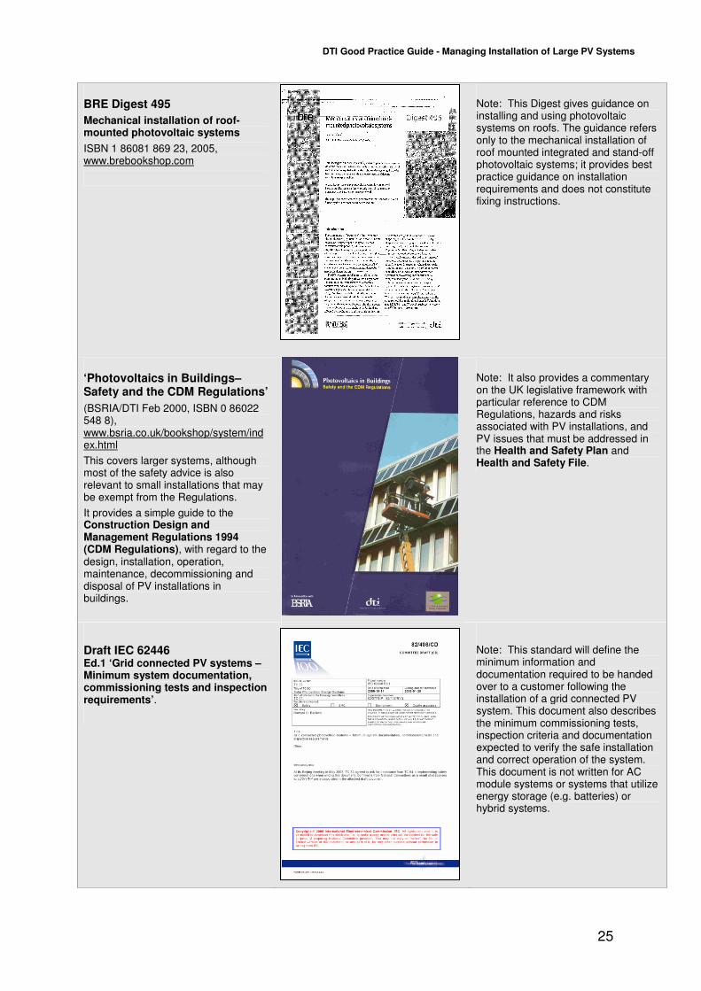
Example Wall Display – St Mary’s Church
Appendix 3
Monitoring of PV systems
Most large scale buildings with PV systems have some sort of performance monitoring. As a minimum these buildings will have a wall display mounted in a prominent location such as the entrance foyer. Wall displays typically provide the following information about the building’s PV system:
• Instantaneous generation from the PV system (in kW)
• Cumulative generation of PV system since commissioning, or cumulative daily generation (in kWh)
• Total amount of CO2 saved to date (in kg CO2) The wall display provides information to the occupants about their building’s PV system, and is a way of promoting the organisation as being environmentally conscious.
Use of a data logger enables information on the PV system to be stored, usually at intervals of 5 or 10 minutes. This can be used to track the performance of the PV system, such as providing a comparison of the energy output over different months as shown in the example of the OpTIC Centre. More sophisticated performance details can be gained from the PV system with the appropriate monitoring equipment, such as reference cells for measuring insolation. This can be used to determine the efficiency of different components
within the system, or different arrays within the system, and the overall efficiency. This information enables any faults or failures within the system to be identified to maximise generation.
Under the LSBIPV programme, information has been collected on a number of parameters as shown below to enable extensive analysis to be undertaken.