
Good Heat Treating Practice - Home - My...
138
Standard for Repair and Remanufacturing of Drill- through Equipment API Standard 16AR First Edition, XXXX 2015 Draft – November 10 2014
Transcript of Good Heat Treating Practice - Home - My...

Standard for Repair and Remanufacturing of Drill-throughEquipment
API Standard 16AR First Edition, XXXX 2015
Draft – November 10 2014

SPECIAL NOTESAPI publications necessarily address problems of a general nature. With respect to particular circumstances, local, state, and federal laws and regulations should be reviewed.
API is not undertaking to meet the duties of employers, manufacturers, or suppliers to warn and properly train and equip their employees, and others exposed, concerning health and safety risks and precautions, nor undertaking their obligations under local, state, or federal laws.
Information concerning safety and health risks and proper precautions with respect to particular materials and conditions should be obtained from the employer, the manufacturer or supplier of that material, or the material safety data sheet.
Nothing contained in any API publication is to be construed as granting any right, by implication or otherwise, for the manufacture, sale, or use of any method, apparatus, or product covered by letters patent. Neither should anything contained in the publication be construed as insuring anyone against liability for infringement of letters patent.
Generally, API standards are reviewed and revised, reaffirmed, or withdrawn at least every five years. Sometimes a one-time extension of up to two years will be added to this review cycle. This publication will no longer be in effect five years after its publication date as an operative API standard or, where an extension has been granted, upon republication. Status of the publication can be ascertained from the API Standards department telephone (202) 682-8000. A catalog of API publications, programs and services is published annually and updated biannually by API, and available through Global Engineering Documents, 15 Inverness Way East, M/S C303B, Englewood, CO 80112-5776.
This document was produced under API standardization procedures that ensure appropriate notification and participation in the developmental process and is designated as an API standard. Questions concerning the interpretation of the content of this standard or comments and questions concerning the procedures under which this standard was developed should be directed in writing to the Director of the Standards department, American Petroleum Institute, 1220 L Street, N.W., Washington, D.C. 20005. [email protected] Requests for permission to reproduce or translate all or any part of the material published herein should be addressed to the Director, Business Services.
API standards are published to facilitate the broad availability of proven, sound engineering and operating practices. These standards are not intended to obviate the need for applying sound engineering judgment regarding when and where these standards should be utilized. The formulation and publication of API standards is not intended in any way to inhibit anyone from using any other practices.
Any manufacturer marking equipment or materials in conformance with the marking requirements of an API standard is solely responsible for complying with all the applicable requirements of that standard. API does not represent, warrant, or guarantee that such products do in fact conform to the applicable API standard.
All rights reserved. No part of this work may be reproduced, stored in a retrieval system, or transmitted by any means, electronic, mechanical, photocopying, recording, or otherwise, without prior written permission from the publisher. Contact the Publisher, API Publishing Services, 1220
L Street, N.W., Washington, D.C. 20005.
Copyright © 2014 American Petroleum Institute

FOREWORD
This standard shall become effective on the date printed on the cover but may be used voluntarily from the date of distribution.
Standards referenced herein may be replaced by other international or national standards that can be shown to meet or exceed the requirements of the referenced standard. Manufacturers electing to use another standard in lieu of a referenced standard are responsible for documenting equivalency. This standard is under the jurisdiction of the API Subcommittee on Drilling Well Control Systems.
This standard replaces the repair and remanufacturing requirements from API 16A.
API publications may be used by anyone desiring to do so. Every effort has been made by the Institute to assure the accuracy and reliability of the data contained in them; however, the Institute makes no representation, warranty, or guarantee in connection with this publication and hereby expressly disclaims any liability or responsibility for loss or damage resulting from its use or for the violation of any federal state, or municipal regulation with which this publication may conflict.
Suggested revisions are invited and should be submitted to the API, Standards Department, 1220 L Street, NW, Washington, DC 20005, or by email to [email protected].

Table of Contents
Contents1. Scope............................................................................................................................12. Normative References................................................................................................23. Terms, Definitions and Abbreviations.........................................................................4
3.1 Terms and Definitions.........................................................................................43.2 Abbreviated terms..............................................................................................13
4. Quality Control Requirements...................................................................................154.1 General...............................................................................................................154.2 Measuring and testing equipment......................................................................15
4.2.1 General...........................................................................................................154.2.2 Pressure-measuring devices...........................................................................15
4.3 Quality control personnel qualifications............................................................154.3.1 Non-destructive examination (NDE) personnel............................................154.3.2 Visual examination personnel........................................................................154.3.3 Welding inspectors........................................................................................164.3.4 Third Party Inspection...................................................................................164.3.5 Equipment certification.................................................................................164.3.6 Other personnel..............................................................................................16
4.4 Quality control requirements for equipment and parts......................................174.4.1 General...........................................................................................................174.4.2 Material requirements....................................................................................174.4.3 End connections.............................................................................................174.4.4 Bolting specification......................................................................................174.4.5 Quality control instructions...........................................................................184.4.6 Non-destructive examination (NDE).............................................................194.4.7 Acceptance status...........................................................................................19
4.5 Quality control requirements for specific equipment and parts.........................194.5.1 Pressure-containing and pressure-controlling parts.......................................204.5.2 Hardness testing.............................................................................................204.5.3 Critical dimensions........................................................................................204.5.4 Traceability....................................................................................................204.5.5 Chemical analysis..........................................................................................214.5.6 Visual examination........................................................................................214.5.7 Surface NDE..................................................................................................214.5.8 Acceptance criteria for MP and LP...............................................................214.5.9 Weld NDE.....................................................................................................224.5.10 Weld NDE - Surface examination (other than visual)...............................224.5.11 Repair welds..............................................................................................224.5.12 Weld NDE — Volumetric examination of fabrication weld.....................224.5.13 Volumetric NDE parts...............................................................................254.5.14 Non-Metallic parts.....................................................................................264.5.15 Annular packers when shipped in a BOP..................................................264.5.16 Assembled equipment................................................................................264.5.17 Closed-preventer test.................................................................................274.5.18 Hydraulic connector pressure test..............................................................27
iv

4.6 Requirements for quality control records..........................................................274.6.1 General...........................................................................................................274.6.2 NACE records requirements..........................................................................274.6.3 Records control..............................................................................................274.6.4 Records to be maintained by remanufacturer................................................28
4.7 Remanufacturing Service levels........................................................................295. Quality Management System Requirements.............................................................31
5.1 Control of Documents........................................................................................315.2 Training and Awareness....................................................................................315.3 Control of testing, measuring, monitoring equipment.......................................315.4 Contract Review................................................................................................32
5.4.1 General...........................................................................................................325.4.2 Determination of Requirements.....................................................................32
5.5 Purchasing Control............................................................................................325.6 Design and Development...................................................................................32
5.6.1 Design and Development Planning...............................................................325.6.2 Design documentation...................................................................................335.6.3 Design and Development Inputs....................................................................335.6.4 Design Verification........................................................................................335.6.5 Design Validation..........................................................................................335.6.6 Control of design and development changes.................................................345.6.7 Control of nonconforming product................................................................345.6.8 Field nonconformity analysis........................................................................34
6. Responsibilities..........................................................................................................356.1 OEM / CEM.......................................................................................................356.2 Repairer / Remanufacturer.................................................................................356.3 Product Owner:..................................................................................................35
7. Repair / Remanufacturing Specification Level Minimum Requirements.................377.1 General...............................................................................................................377.2 Current Equipment Manufacturer (CEM).........................................................377.3 Requirements for Pressure Testing....................................................................37
7.3.1 General...........................................................................................................377.3.2 Hydrostatic Testing........................................................................................377.3.3 Operating Chamber Pressure Test.................................................................387.3.4 Closed-preventer test.....................................................................................387.3.5 Shear test........................................................................................................387.3.6 Rams lock test................................................................................................397.3.7 Elastomeric Seal Requirements.....................................................................397.3.8 Wellbore Sealing Components and Consumables.........................................397.3.9 Operating Sealing Components and Consumables........................................39
7.4 Dimensional check.............................................................................................397.5 NDE – Initial Inspection....................................................................................407.6 Inspection on closure bolting (pressure retaining).............................................407.7 Visual Inspection at disassembly.......................................................................407.8 Drift Test............................................................................................................417.9 Replacement Parts.............................................................................................41

7.10 General Equipment Specifications....................................................................417.11 Documentation...................................................................................................417.12 Failure Reporting...............................................................................................41
8. Materials....................................................................................................................428.1 General...............................................................................................................428.2 Metallic Parts.....................................................................................................428.3 Non-metallic parts.............................................................................................428.4 Base metal material Identification.....................................................................43
8.4.1 General...........................................................................................................438.4.2 Original Material Test Records (MTRs)........................................................438.4.3 Determining Hardness and approximate ultimate tensile values:..................438.4.4 Determining Chemical Composition:............................................................44
8.5 Pressure-containing members............................................................................448.5.1 Property requirements....................................................................................448.5.2 Heat treating...................................................................................................458.5.3 Chemical composition...................................................................................468.5.4 Material qualification.....................................................................................468.5.5 Qualification test coupons (QTC)..................................................................478.5.6 Equivalent round (ER)...................................................................................478.5.7 Processing......................................................................................................488.5.8 Tensile and impact testing.............................................................................498.5.9 Hardness testing.............................................................................................49
9. Welding requirements................................................................................................499.1 General...............................................................................................................499.2 Weldment design and configuration..................................................................50
9.2.1 Pressure-containing fabrication weldments...................................................509.2.2 Load-bearing weldments...............................................................................509.2.3 Repair welds..................................................................................................509.2.4 Tack welds.....................................................................................................519.2.5 Weld surfacing (overlay) for corrosion resistance and wear resistance for material surface property controls.............................................................................51
9.3 Welding controls................................................................................................549.3.1 Procedures......................................................................................................549.3.2 Application....................................................................................................549.3.3 Designed welds..............................................................................................549.3.4 Preheating......................................................................................................549.3.5 Instrument calibration....................................................................................559.3.6 Materials........................................................................................................559.3.7 Post-weld heat treatment................................................................................55
9.4 Welding procedure and performance qualifications..........................................569.4.1 General...........................................................................................................569.4.2 Base metals....................................................................................................569.4.3 Filler material qualification...........................................................................569.4.4 Chemical Analysis.........................................................................................579.4.5 Heat-treat condition.......................................................................................579.4.6 Procedure qualification record.......................................................................57
vi

9.5 Other Welding Qualification requirements.......................................................579.5.1 ASME Section IX, Article I — Welding general requirements....................579.5.2 ASME Section IX, Article II — Welding procedure qualifications..............599.5.3 ASME Section IX, Article III — Welding performance qualifications........609.5.4 ASME Section IX, Article IV — Welding data............................................61
9.6 Other requirements............................................................................................629.7 Documentation Requirements...........................................................................62
10. Decommissioning..................................................................................................6211. Marking requirements............................................................................................62
11.1 Low-stress-area marking...................................................................................6311.2 High-stress-area marking...................................................................................6311.3 Weld metal overlays..........................................................................................6311.4 Wellbore non-metallic components...................................................................6311.5 Non-wellbore non-metallic components............................................................6311.6 Specific codification requirements of equipment..............................................63
12. Storing and shipping..............................................................................................6412.1 Storing for periods greater than 30 days............................................................64
12.1.1 Draining after testing.................................................................................6412.1.2 Rust prevention..........................................................................................6412.1.3 Connection-surface protection...................................................................6412.1.4 Hydraulic operating system.......................................................................6412.1.5 Elastomeric seals.......................................................................................6412.1.6 Ring gaskets...............................................................................................64
12.2 Shipping.............................................................................................................6413. Certification...........................................................................................................64
13.1 Certificate of Conformance...............................................................................6413.2 Statement of Compatibility................................................................................65
13.2.1 Statement of Fact.......................................................................................6513.3 Certificate of Service.........................................................................................65
Annex A (Normative) General Equipment Specifications................................................66Annex B (Normative) Manufacturing Data Book Requirements......................................69Annex C (Normative) Product History File Requirements...............................................71Annex D (Normative) Failure reporting............................................................................73Annex E (Normative) Design ownership..........................................................................74Annex F (Informative) Minimum requirements for Certificate Of Conformance (COC).75Annex G (Informative) Recommended weld preparation design dimensions...................77Annex H (Normative) Qualification of heat-treating equipment......................................80Annex I (Normative) Equivalent Rounds (ER) models.....................................................83Annex J (Normative) Replacement parts...........................................................................85Annex K (Normative) Location of Charpy V-notch impact tests for weld qualification. .86
1. ScopeThis Standard specifies requirements for repair, remanufacturing, testing, inspection, welding, marking, certification, recertification, handling, storing and shipping of drill-

through equipment used for drilling for petroleum and natural gas built under API 16A and API 6A equipment produced prior to existence of API 16A.
Repair and remanufacturing under this standard excludes work performed on equipment under maintenance.
This standard defines various Repair / Remanufacturing specification levels (RSLs) for the equipment identified below as well as the mandatory equipment traceability that is required to prove compliance.
The repair and remanufacturing identified in this standard shall be supported by the Original Product Definition or Current Product Definition.
This standard is applicable to and establishes requirements for the following specific equipment:
1. ram blowout preventers;
2. ram blocks, operators, packers and top seals;
3. annular blowout preventers;
4. annular packing units;
5. hydraulic connectors;
6. drilling spools;
7. adapters;
8. loose connections;
9. clamps.
Dimensional interchangeability is limited to end and outlet connections. Simplified examples of surface and subsea equipment defined by this standard are shown in Figures 1 and 2.
Requirements for failure reporting are outlined in Annex D.
viii

9 API SPECIFICATION 16AR
Key:1. Ring gaskets API 6A 7. Wellhead API 6A2. Annular BOP API 16A 8. Casing API 5CT / 5L3. Clamp API 16A 9. End and outlet connections API 6A4. Ram BOP API 16A 10. Drill-through equipment API 16A5. Drilling / spacer spool API 16A 11. Wellhead equipment API 6A6. Valve API 6A
Figure 1 — Simplified example of surface drill-through equipment

STANDARD FOR REPAIR AND REMANUFACTURING OF WELL CONTROL EQUIPMENT 10
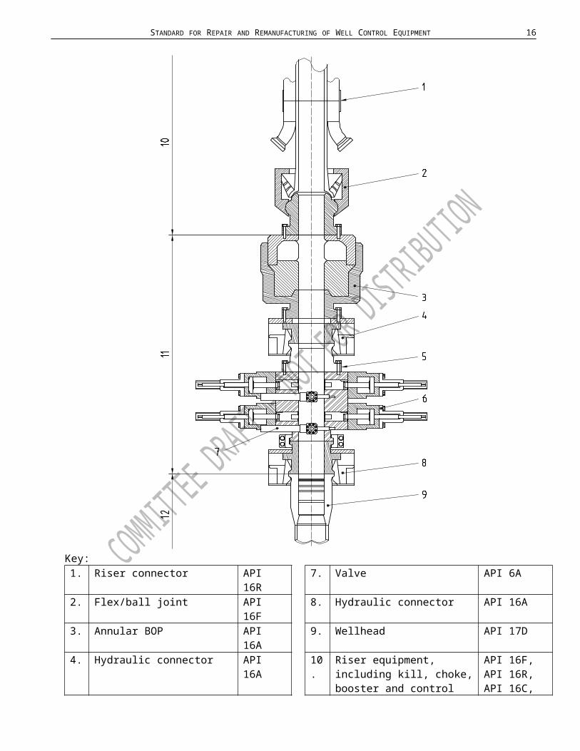
Key:1. Riser connector API 16R 7. Valve API 6A2. Flex/ball joint API 16F 8. Hydraulic connector API 16A3. Annular BOP API 16A 9. Wellhead API 17D4. Hydraulic connector API 16A 10. Riser equipment, including
kill, choke, booster and control fluid conduit lines
API 16F,API 16R,API 16C,API 16D
5. Adapter API 16A 11. Drill-through equipment API 16A6. Ram BOP API 16A 12. Wellhead equipment API 17D
Figure 2 — Simplified example of subsea drill-through equipment

11 API SPECIFICATION 16AR
2. Normative ReferencesThe following referenced documents are indispensable for the application of this document. For dated references, only the edition cited applies. For undated references, the latest edition of the referenced document (including any amendments) applies.
APIAPI Specification 5DP, Specification for Steel pipes for Use as Drill Pipe
API Specification 6A, Specification for Wellhead and Christmas Tree Equipment
API Specification 16A, Specification for Drill-through Equipment
API Specification 20E, Specification for Alloy and Carbon Steel Bolting for Use in the Petroleum and Natural Gas Industries
API Specification Q1: Specification for Quality Management System Requirements for Manufacturing Organizations for the Petroleum, Petrochemical and Natural Gas Industry
ASMEASME Boiler and Pressure Vessel Code Section V, Article 5, UT Examination Methods for Materials and Fabrication
ASME Boiler and Pressure Vessel Code Section IX, Articles I, II, III and IV
ASME B40.100 Pressure Gauges and Gauge Attachments
ASME BPVC section VIII, DIV1, UCS-56 and B31.1 section 132.5.
ASME B&PVC Section VIII Div 2, paragraph 6.4.5.3
ASNTASNT-SNT-TC-1A, Recommended Practice for Personnel Qualification and Certification in Nondestructive Testing
ASTMASTM A370, Test Methods and Definitions for Mechanical Testing of Steel Products
ASTM D395, Standard Test Methods for Rubber Property — Compression Set
ASTM D412, Test Methods for Vulcanized Rubber, Thermoplastic Rubbers and Thermoplastic Elastomers
ASTM D471, Standard Test Method for Rubber Property — Effect of Liquids
ASTM D1414, Standard Test Methods for Rubber O-Rings
ASTM D1415, Standard Test Method for Rubber Property — International Hardness
ASTM D1418, Standard Practice for Rubber and Rubber Lattices — Nomenclature
ASTM D2240, Test Method for Rubber Property — Durometer Hardness
ASTM E10, Standard Test Method for Brinell Hardness of Metallic Materials
ASTM E18, Standard Test Methods for Rockwell Hardness of Metallic MaterialsASTM E94, Standard Guide for Radiographic Testing

STANDARD FOR REPAIR AND REMANUFACTURING OF WELL CONTROL EQUIPMENT 12
ASTM E140, Hardness Conversion Tables for Metals
ASTM E165, Standard Test Method for Liquid Penetrant Examination
ASTM E384, Standard Test Method for Knoop and Vickers Hardness of MaterialsASTM E569, Standard Practice for Acoustic Emission Monitoring of Structures During Controlled Simulation
ASTM E709, Standard Guide for Magnetic Particle Examination
ISOISO 2859-1:1989, Sampling procedures for inspection by attributes — Part 1: Sampling plans indexed by acceptable quality level (AQL) for lot-by-lot inspection
ISO 6506-1, Metallic materials, Brinell hardness test, Part 1: Test method
ISO 6507-1, Metallic materials, Vickers hardness test, Part 1: Test method
ISO 6508- All parts, Metallic materials, Rockwell hardness test
ISO 6892, Metallic materials, Tensile testing at ambient temperature
ISO 13665, Seamless and welded steel tubes for pressure purposes — Magnetic particle inspection of the tube body for the detection of surface imperfections
ISO 9712, International Standard for Nondestructive Testing Personnel Qualification and Certification
CSWIP, Requirements for the Certification of Visual Welding Inspectors (Level 1), Welding Inspectors (Level 2) and Senior Welding Inspectors (Level 3) (fusion welding) in accordance with the requirements of BS EN ISO 176371:2011
ISO 15156, Materials for use in H2S-containing environments in oil and gas production, all parts.
NACENACE MR0175, Sulfide Stress Cracking Resistant Metallic Materials for Oilfield Equipment
SAESAE AMS-H-6875B, Heat Treatment of Steel Raw Materials
SAE AMS 2750E, Pyrometry
Footnote:1) American Society of Mechanical Engineers, Three Park Avenue, New York, NY 10016-5990, USA.2) American Society for Nondestructive Testing, 4153 Arlingate Plaza, Columbus, OH 43228-0518,
USA.3) American Society for Testing and Materials, 100 Barr Harbor Drive, West Conshohocken, PA 19428-
2959, USA.4) International Organization for Standardization, 1, ch. de la Voie-Creuse, Case postale 56, CH-1211
Geneva 20, Switzerland, www.iso.org.5) NACE International, 1440 South Creek Drive, Houston, Texas 77084-4906, www.nace.org.6) SAE International, 400 Commonwealth Drive, Warrendale, PA 15096-0001, USA.

13 API SPECIFICATION 16AR
3. Terms, Definitions and Abbreviations3.1Terms and Definitions
For the purpose of this document, the following terms and definitions apply.
3.1.1acceptance criteriadefined limits placed on characteristics of materials, products or service
3.1.2adapterpressure-containing piece of equipment having end connections of different nominal size designation and/or pressure rating
3.1.3annular blowout preventerblowout preventer that uses a shaped elastomeric sealing element to seal the space between the tubular and the wellbore or an open hole
3.1.4blind-shear ram BSRclosing and sealing component in a ram blowout preventer that first shears the tubular in the wellbore and then seals off the bore or acts as a blind ram if there is no tubular in the wellbore
3.1.5blind ramclosing and sealing component in a ram blowout preventer that seals the open wellbore
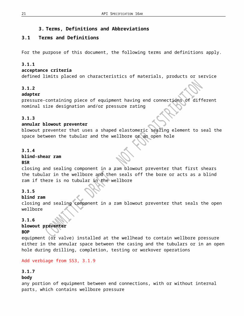
3.1.6blowout preventer BOPequipment (or valve) installed at the wellhead to contain wellbore pressure either in the annular space between the casing and the tubulars or in an open hole during drilling, completion, testing or workover operations
Add verbiage from S53, 3.1.9
3.1.7bodyany portion of equipment between end connections, with or without internal parts, which contains wellbore pressure
3.1.8boltingAll threaded fasteners, tap-end studs, double-ended studs, headed bolts, cap screws, screws, and nuts other than closure bolting.
3.1.9calibrationcomparison and adjustment to a standard of known accuracy

STANDARD FOR REPAIR AND REMANUFACTURING OF WELL CONTROL EQUIPMENT 14

15 API SPECIFICATION 16AR
3.1.10casing-shear ramclosing component in a ram blowout preventer that shears the tubular in the wellbore and does not provide a seal on the wellbore
3.1.11casting (noun)object at or near finished shape obtained by solidification of a substance in a mold
3.1.12Certificate of ConformanceCOCdocument in which the Manufacturer, Repairer, Remanufacturer, or recognized technical authority certifies that the assembly or part is in conformance to the mentioned standard(s), specifications and guidelines in accordance with the original or current product definition, including design changes resulting from a malfunction or failure history of drill-through equipment.
3.1.13Certificate of ServiceCOSdocument in which the equipment Manufacturer, Repairer, Remanufacturer, recognized technical authority / Owner or Operator certifies that the equipment has been inspected, properly maintained and tested in accordance with the applicable Equipment Owner’s maintenance program and manufacturers guidelines.
3.1.14chemical analysisdetermination of the chemical composition of material
3.1.15clamp (noun)device with internal angled shoulders used to fasten mating hubs
3.1.16closure boltingthreaded fasteners used to assemble on join wellbore pressure-containing parts other than end and outlet connections.
3.1.17conformancesatisfying the specified requirements in every detail
3.1.18corrosion-resistant ring groovering groove lined with metal resistant to metal-loss corrosion
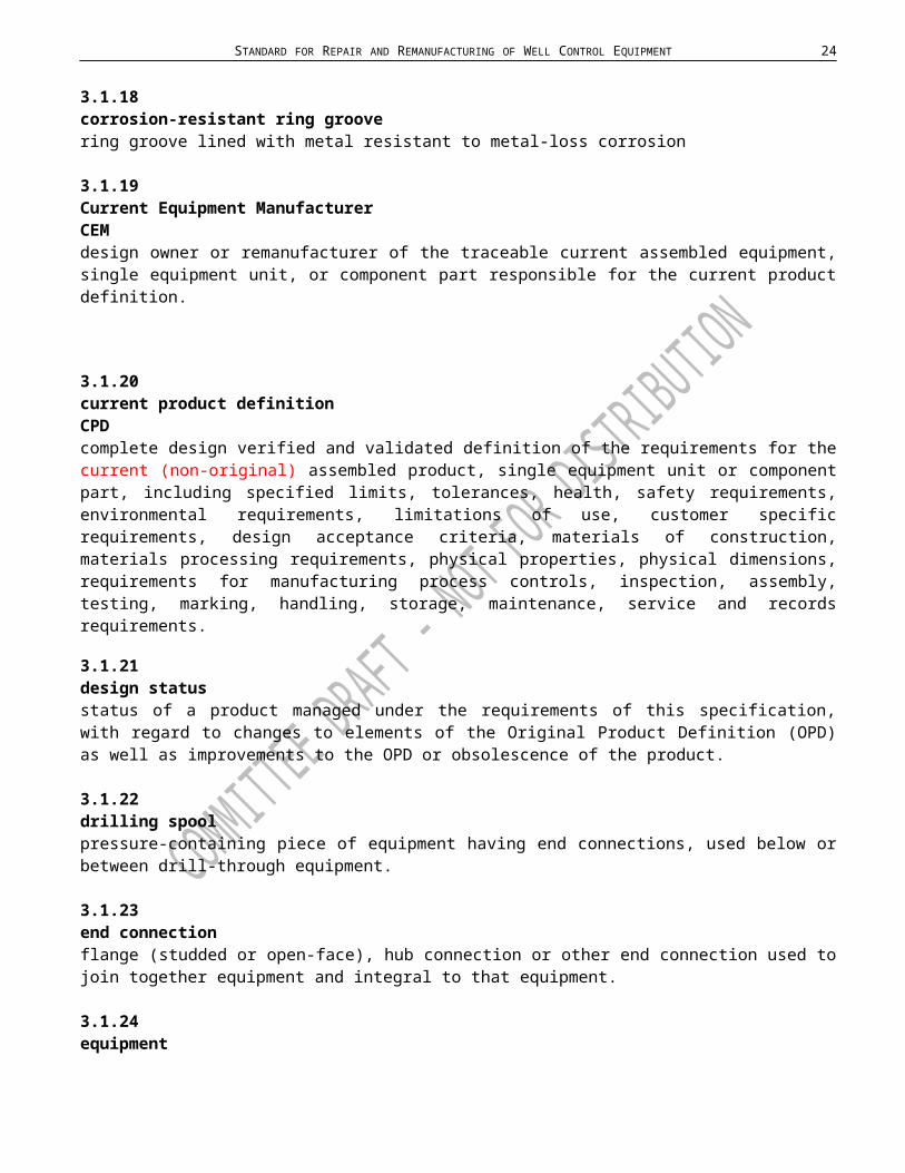
3.1.19Current Equipment ManufacturerCEMdesign owner or remanufacturer of the traceable current assembled equipment, single equipment unit, or component part responsible for the current product definition.
STANDARD FOR REPAIR AND REMANUFACTURING OF WELL CONTROL EQUIPMENT 16
3.1.20current product definition CPD complete design verified and validated definition of the requirements for the current (non-original) assembled product, single equipment unit or component part, including specified limits, tolerances, health, safety requirements, environmental requirements, limitations of use, customer specific requirements, design acceptance criteria, materials of construction, materials processing requirements, physical properties, physical dimensions, requirements for manufacturing process controls, inspection, assembly, testing, marking, handling, storage, maintenance, service and records requirements.
3.1.21design statusstatus of a product managed under the requirements of this specification, with regard to changes to elements of the Original Product Definition (OPD) as well as improvements to the OPD or obsolescence of the product.
3.1.22drilling spoolpressure-containing piece of equipment having end connections, used below or between drill-through equipment.
3.1.23end connectionflange (studded or open-face), hub connection or other end connection used to join together equipment and integral to that equipment.
3.1.24equipmentany single completed unit that can be used for its intended purpose without further processing or assembly
3.1.25fabrication weldweld that joins two or more pieces of metal
3.1.26flangeprotruding rim, with holes to accept bolts and having a sealing mechanism, used to join pressure-containing equipment together by bolting to another flange
3.1.xxflange boltingstuds and nuts used to join API 6A flange end and outlet connections.
3.1.27forging (noun)shaped metal part formed by the forging method
3.1.28full-penetration weldweld that extends throughout the complete wall section of the parts joined

17 API SPECIFICATION 16AR
3.1.29heatcast lot material originating from a final melt
NOTE For remelted alloys, a heat is defined as the raw material originating from a single remelted ingot.
3.1.30heat-affected zoneHAZportion of the base metal which has not been melted, but whose mechanical properties or microstructure has been altered by the heat of welding or cutting
3.1.31heat treatmentheat treatingalternate steps of controlled heating and cooling of materials for the purpose of changing physical or mechanical properties
3.1.32heat treatment loadmaterial moved as a batch through one heat treatment cycle
3.1.33hot-work (verb)deform metal plastically at a temperature above the recrystallization temperature
3.1.34hubprotruding rim with an external angled shoulder and a sealing mechanism used to join pressure-containing equipment
3.1.35hydraulic connectorhydraulically actuated drill-through equipment that locks and seals on end connections
3.1.36indicationvisual sign of cracks, pits or other abnormalities found during liquid penetrant, magnetic particle, ultrasonic and radiography examinations.
3.1.37integral (adjective)parts joined by the forging, casting or welding process
3.1.38leakagevisible passage of pressurized fluid from the inside to the outside of the pressure-containment area of the equipment being tested
3.1.39loose connectionflange (studded or open-face), hub connection or other end connection used to join together equipment, but not integral to the equipment

STANDARD FOR REPAIR AND REMANUFACTURING OF WELL CONTROL EQUIPMENT 18
3.1.40maintenanceupkeep of well control equipment which is performed in accordance with the equipment owner’s PM program and the manufacturer’s guidelines.
NOTE These procedures may include but are not limited to, inspections, function testing, pressure testing, non-destructive examination and change out of parts.
3.1.41major repair weldweld that is the greater in thickness of either 1 inch or 25 percent of the original base metal thickness
3.1.42manufacturerThe OEM or CEM of the product or part.
3.1.43manufacturing databookMDBcomposite file of records from a traceable API product which includes all records associated with the original API product manufacturing including certification records as required by this specification.
3.1.44original equipment manufacturerOEMdesign owner or manufacturer of the traceable assembled equipment, single equipment unit, or component part owning the original product definition.
3.1.45original product definition OPD complete design verified and validated definition of the requirements for the original assembled product, single equipment unit or component part, including specified limits, tolerances, health, safety requirements, environmental requirements, limitations of use, customer specific requirements, design acceptance criteria, materials of construction, materials processing requirements, physical properties, physical dimensions, requirements for manufacturing process controls, inspection, assembly, testing, marking, handling, storage, maintenance, service and records requirements.
3.1.46partindividual piece used in the assembly of a single unit of equipment
3.1.47post-weld heat treatmentPWHTheating and cooling a weldment in a controlled manner to obtain desired properties
3.1.48

19 API SPECIFICATION 16AR
pressure-containing part or memberpressure-containing member or part exposed to wellbore fluids whose failure to function as intended would result in a release of wellbore fluid to the environment
NOTE Examples include bodies, bonnets and connecting rods.
3.1.49pressure-containing weldweld whose failure will reduce the pressure-containing integrity of the component
3.1.50pressure-controlling partparts intended to control or regulate the movement of wellbore fluids
NOTE Examples include packing elements, rams, and replaceable seats within a pressure-containing member or part.
3.1.51pressure-retaining partpart not exposed to wellbore fluids whose failure to function as intended will result in a release of wellbore fluid to the environment
NOTE Examples include closure bolts and clamps.
3.1.52procedure qualification recordPQRrecord of the welding data used to make the test weldment containing the actual values or ranges of the essential and supplementary essential variables used in preparing the test weldments, including the test results
3.1.53product ownerowner of the product repaired or remanufactured in conformance with this document
3.1.54product history filePHFcomposite file of records from a traceable API product which includes all records associated with the original API product repair and remanufacturing, including certification records required by this specification.
3.1.55ram blowout preventerblowout preventer that uses metal blocks with integral elastomer seals to seal off pressure on a wellbore with or without tubulars in the bore
3.1.56rated working pressuremaximum internal pressure that the equipment is designed to contain and/or control
3.1.57recognized technical authorityManufacturer / Remanufacturer holding the manufacturing and quality licenses, or registered professional engineer, or a technical classification society, or engineering firm in which its employees

STANDARD FOR REPAIR AND REMANUFACTURING OF WELL CONTROL EQUIPMENT 20
hold appropriate licenses to perform the verification in the appropriate jurisdiction, or evidence to demonstrate that the individual, society, or firm has the applicable expertise and experience necessary to perform the required verifications.
3.1.58record (noun)document or dataset created and maintained that provides objective evidence of activities performed, results achieved or statements made.
3.1.59remanufactureprocess of disassembly, reassembly and testing of drill-through equipment, with or without the replacement of parts, in which machining, welding, heat treatment or other manufacturing operation is employed
3.1.60remanufacturerAn organization that performs the repair or remanufacturing work.
3.1.61repairprocess of disassembly, reassembly and testing of drill-through equipment, with or without the replacement of parts
NOTE Repair does not include machining, welding, heat treating or other manufacturing operation of component parts and does not include the replacement of pressure-containing part(s) or member(s). Repair may include replacement of parts other than pressure-containing part(s) or member(s).
3.1.62repair weldwelding performed subsequent to original heat treatment other than base weld repair
3.1.63serializationassignment of a unique code to individual parts and/or pieces of equipment to maintain records
3.1.??skim cutre-facing of a machined surface removing no more than 0.010 - .125 inch (discuss to define allowable range).
re-facing of a machined surface within allowable tolerances established by the manufacturer or remanufacturer which have been subjected to the verification standards within 16A and which does not exceed material removal of .060”
3.1.64stabilizedpressure testing in a state in which the initial pressure-decline rate has decreased to within the manufacturer's specified rate
21 API SPECIFICATION 16AR
NOTE Pressure decline can be caused by such things as changes in temperature, setting of elastomer seals or compression of air trapped in the equipment being tested.
3.1.65Statement of Compatibilitydocument in which a Manufacturer, Repairer, Remanufacturer, or recognized technical authority states that a component part meets or exceeds the product performance requirements as defined in 16A and is compatible with the assembly it is intended for.
3.1.66Statement of FactSOFdocument in which the Manufacturer, Repairer, Remanufacturer, or recognized technical authority certifies that the repair performed was made with in accordance with the scope defined by the Owner.
NOTE A Statement of Fact does not fulfil the requirements of a Certificate of Conformance or other documentation verifying product design.
3.1.67stress reliefcontrolled heating of material to a predetermined temperature for the purpose of reducing any residual stresses
3.1.68trepan (verb)produce a hole through a part by boring a narrow band or groove around the circumference of the hole and removing the solid central core of material
3.1.69variable-bore ramVBRclosing and sealing component in a ram blowout preventer that is capable of sealing on a range of tubular sizes
3.1.70visual examinationexamination of parts and equipment for visible defects in material and workmanship
3.1.71volumetric non-destructive examinationexamination for internal material defects by radiography, acoustic emission or ultrasonic testing
3.1.72weld (verb)act of fusing materials, with or without the addition of filler materials
3.1.73weld groovearea between two metals to be joined that has been prepared to receive weld filler metal
3.1.74weldingapplication of any one of a group of welding processes, which applies heat energy sufficient to melt and join one or more pieces of metal through localized fusion and coalescence

STANDARD FOR REPAIR AND REMANUFACTURING OF WELL CONTROL EQUIPMENT 22
3.1.75welding procedure specificationWPSwritten welding procedure that is qualified to provide direction for welding in accordance with requirements of this standard and describing the specific essential, nonessential, and supplementary essential variables required for each welding process.
NOTE These variables and their meanings are defined, respectively, in Article II, QW-250 through QW-280 and Article IV of the ASME Boiler & Pressure Vessel Code Section IX–Welding and Brazing Qualifications.
3.1.76weldmentportion or area of a component on which welding has been performed. A weldment includes the weld metal, the heat-affected zone (HAZ), and the base metal unaffected by the heat of welding
3.1.77yield strengthstress level, measured at room temperature, at which material plastically deforms and will not return to its original dimensions when the stress is released
NOTE 1 The term is expressed in Newton’s per square millimeter (pounds per square inch) of loaded area.
NOTE 2 All yield strengths specified in this standard are considered as being the 0,2 % yield offset strength in accordance with ISO 6892 or ASTM A370.

23 API SPECIFICATION 16AR
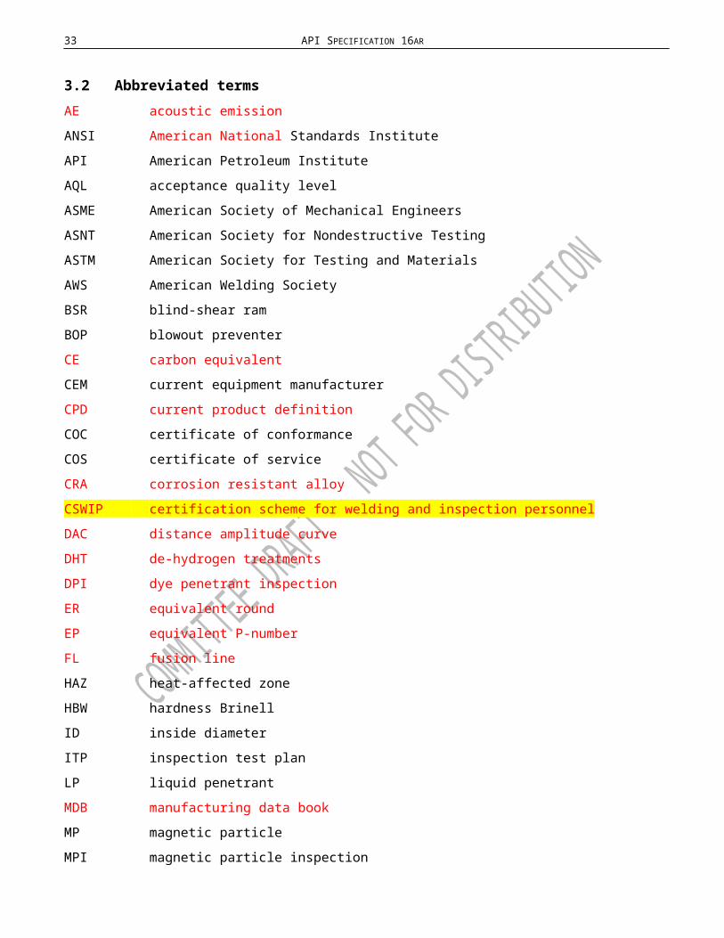
3.2Abbreviated termsAE acoustic emission
ANSI American National Standards Institute
API American Petroleum Institute
AQL acceptance quality level
ASME American Society of Mechanical Engineers
ASNT American Society for Nondestructive Testing
ASTM American Society for Testing and Materials
AWS American Welding Society
BSR blind-shear ram
BOP blowout preventer
CE carbon equivalent
CEM current equipment manufacturer
CPD current product definition
COC certificate of conformance
COS certificate of service
CRA corrosion resistant alloy
CSWIP certification scheme for welding and inspection personnel
DAC distance amplitude curve
DHT de-hydrogen treatments
DPI dye penetrant inspection
ER equivalent round
EP equivalent P-number
FL fusion line
HAZ heat-affected zone
HBW hardness Brinell
ID inside diameter
ITP inspection test plan
LP liquid penetrant
MDB manufacturing data book
MP magnetic particle
MPI magnetic particle inspection
MTR material test record
NACE National Association of Corrosion Engineers
NDE nondestructive examination
OD outside diameter
STANDARD FOR REPAIR AND REMANUFACTURING OF WELL CONTROL EQUIPMENT 24
OEC other end connection
OEM original equipment manufacturer
OPD original product definition
PHF product history file
PM preventive maintenance
PMI positive material identification
PQR procedure qualification record
PWHT post-weld heat treatment
QMS quality management system
Q&T quenched and tempered
RSL remanufacturing specification level
SOF statement of fact
SSC Sulfide Stress Cracking
SST stainless steel
TPI third party inspection
UNS unified numbering system
UTS ultimate tensile strength
VBR variable-bore ram
WPS welding procedure specification
YS yield strength
SMYS specified minimum yield strength

25 API SPECIFICATION 16AR
4. Quality Control Requirements4.1GeneralThis clause specifies the quality control requirements for equipment repaired and remanufactured to meet this specification. Ed to clarify whether this is Standard or Specification.
4.2Measuring and testing equipment 4.2.1 GeneralEquipment used to inspect, test or examine material or other equipment shall be identified, controlled, calibrated and adjusted at specified intervals in accordance with documented manufacturer requirements, and consistent with recognized standards specified by the manufacturer, to maintain the accuracy required by this specification.
4.2.2 Pressure-measuring devices4.2.2.1 Type and Accuracy Test pressure-measuring devices shall be accurate in accordance with 16A.
Pressure tests shall be documented in a chart(linear or circular) in the Product History File (PHF) and Manufacturing Data Book (MDB).
The record shall identify the recording device, calibration due date and shall be dated and signed.
4.2.2.2 Calibration procedurePressure-measuring devices shall be calibrated with a master pressure-measuring device or a deadweight tester to at least three equidistant points of full scale (excluding zero and full scale as required points of calibration).
4.2.2.3 Calibration IntervalsIntervals shall be established for calibrations based on repeatability and degree of usage.
Calibration intervals shall be a maximum of three months until recorded calibration history can be established by the manufacturer and new intervals established demonstrating the ability to retain accuracy after a period of time and after repeated use. The date of the last test may be noted on the front of the gauge.
4.3Quality control personnel qualifications4.3.1 Non-destructive examination (NDE) personnel Personnel performing NDE shall be qualified in accordance with the manufacturer's documented training program that is based on the requirements specified in ISO 9712 or ASNT SNT-TC-1A.
4.3.2 Visual examination personnel Personnel performing visual examinations, including welders, shall take and pass an annual vision examination in accordance with the manufacturer's documented procedures that meet the applicable requirements of ISO 9712 or ASNT SNT-TC-1A.

STANDARD FOR REPAIR AND REMANUFACTURING OF WELL CONTROL EQUIPMENT 26
4.3.3 Welding inspectorsPersonnel performing visual inspection of welding operations and completed welds shall be qualified to one of the following:
1) AWS Senior Certified Welding Inspector;
2) AWS Certified Welding Inspector;
3) AWS Certified Associate Welding Inspector;
4) CSWIP Certified Visual Welding Inspectors (Level 1);
5) CSWIP Certified Welding Inspectors (Level 2);
6) CSWIP Certified Senior Welding Inspectors (Level 3)
7) Welding inspector certified by the manufacturer's documented training program
The manufacturer shall have written procedures:
1) Defining the In-house welding inspector certification program including training syllabus, Instructor qualification requirements, length of certification and renewal requirements;.
2) Defining the roles, responsibilities, authority and accountability of a welding inspector;
3) Defining essential welding variables and equipment monitoring;
4) Defining Welding, Weld NDE and PWHT audits. Internal Audits shall be performed at least annually, covering all on-site areas and shifts. Supplier Audits shall be performed in accordance with the Manufacturers written procedure for Validation of Supplier Processes
4.3.4 Third Party InspectionIf Third Party Inspection is used, the following applies:
1) Third Party Inspectors (TPI) shall be competent based on the appropriate education, training, skills and experience needed to perform the inspection service and certification related product requirements defined in the inspection scope.
2) Evidence of the determination of competence of TPI personnel shall be recorded and maintained by the TPI company in accordance with their QMS documented procedures and requirements for competence.
3) The TPI scope shall be clearly defined in the purchase order by the client.
4) The TPI requirements defined in the purchase order shall be included in the Inspection Test Plan for the product.
4.3.5 Equipment certificationEquipment certification shall be approved by a Recognized Technical Authority.
4.3.6 Other personnel All other personnel performing measurements, inspections, or tests for acceptance shall be qualified and competent in accordance with the manufacture’s quality management systems documented procedures

27 API SPECIFICATION 16AR
and requirements, that meet the requirements of API Q1 or equivalent internationally recognized standard.
4.4Quality control requirements for equipment and parts4.4.1 General All pressure-containing and pressure-controlling parts exposed to wellbore fluid shall be in conformance with the requirements of NACE MR0175 or ISO 15156 (all parts).
4.4.2 Material requirementsMaterial used for (removed pressure-containing) parts or members shall conform to the requirements of API 16A with the exceptions noted in Table 3 according to RSL.
4.4.3 End connections4.4.3.1 FlangesType 6B and 6BX blind flanges shall conform to the dimensional requirements of API 6A.
4.4.3.2 HubsDimensions of 16B and 16BX blind hubs shall conform to API 16A with applicable size and pressure rating.
4.4.3.3 Other end connections (OECs)The design and configuration of blind OECs shall conform to API 16A. OEM product definition requirements shall be met.
4.4.3.4 AdaptersEnd connections shall meet the all the design and material requirements of API-16A. All connections shall have a size designation and pressure rating.
4.4.4 Bolting specificationAll bolting selection for surface and subsea pressure control equipment shall consider the maximum hardness requirements, in relation to the operational environment, selected corrosion protection system, coating and plating in order to prevent hydrogen embrittlement
The method of applying the coating to bolting shall ensure that damage through delayed embrittlement (hydrogen embrittlement) is avoided.
Bolting selection for offshore / marine application shall be resistant for high chlorides environment.
Applications of plated low alloy steel bolts, not in conformance ASTM B633, and B850 specifications shall be separately qualified for the application.
CRA bolting selection for surface and subsea pressure control equipment shall consider galvanic corrosion and prevention thereof.
Oversizing of nut threads or under sizing of bolt threads is not permissible.

STANDARD FOR REPAIR AND REMANUFACTURING OF WELL CONTROL EQUIPMENT 28
4.4.4.1 Closure BoltingClosure bolting and other parts shall conform to, or exceed, the manufacturer's written specification and API 16A standard revision under which originally built.
Closure bolting for surface BOP’s shall conform to Table-ATable A — Bolting specification
Bolt size uncoated Coated (painted)
Plated CRA
All sizes API 20E, BSL-1 API 20E, BSL-1 API 20E, BSL-1, SR-1 API 20F, BSL-2
Closure bolting for subsea BOP’s shall conform to Table-BTable B — Bolting specification
Bolt size Uncoated Coated (painted)
Plated CRA
All sizes API 20E, BSL-2 API 20E, BSL-2 API 20E, BSL-2, SR-1 API 20F, BSL-2
The manufacturer shall retain certified material test reports and individual-heat-traceability records for all closure bolting, as required.
The continuous cast method shall not be used for subsea bolting when the micro hardness in the bolt fabrication process exceeds 34 HRC.
4.4.4.2 Flange boltingNuts and bolts used to flange end and outlet connections shall be in conformance with API 6A.
Additionally studs and nuts specification for surface flange bolting shall conform to the requirements of Table-A.
Additionally studs and nuts specification for subsea flange bolting shall conform to the requirements of Table-B.
4.4.4.3 Studs and nuts other than closure bolting or flange boltingStuds and nuts other than closure bolting shall conform to, or exceed, the manufacturer's written specification and API 6A standard revision under which originally built.
Studs and nuts for surface drill through equipment other than closure bolting or flange bolting shall conform to the requirements of Table-A.
Studs and nuts for subsea drill through equipment other than closure bolting or flange bolting shall conform to the requirements of Table-B.
The manufacturer shall retain certified material test reports and individual-heat-traceability records for all closure bolting, as required.

29 API SPECIFICATION 16AR
4.4.5 Quality control instructionsAll quality control work shall be controlled by the manufacturer's documented instructions, which includes an appropriate Inspection Test Plan (ITP) or other methodology that provides an auditable tracking document with quantitative and qualitative acceptance criteria.
4.4.6 Non-destructive examination (NDE)NDE instructions shall be detailed regarding the requirements of this International Standard and those of all applicable nationally or internationally recognized standards specified by the manufacturer. All NDE instructions shall be approved by a NDE Level III examiner.
4.4.6.1 NDE qualification levelsNDE level I:
a) The NDE Level I is qualified to perform system calibrations, Implement techniques and conduct limited evaluation in the NDE method in which the individual is certified.
b) The NDE Level I does not Interpret test results for acceptance or rejection.
NDE Level II:
a) The NDE Level Il is qualified to setup and calibrate equipment, Interpret and evaluate results with respect to applicable codes, standards, and specifications.
b) The NDT Level Il is familiar with the scope and limitations of the used methods for which qualified.
c) The NDE Level II can provide training of NDE Level I personnel.
d) The NDE Level II is qualified to prepare written Instructions, and report the NDE results.
NDE Level III:
a) The NDE Level III is qualified to select the appropriate NDE techniques based on knowledge of materials, fabrication methods and product design for the part.
b) The NDE Level III is responsible to establish techniques and procedures for the examination of a part.
c) The NDT Level III evaluates and interprets the results of the NDE method in conformance with the codes, standards and specifications.
d) The NDE Level III establishes acceptance criteria where none are available.
e) The NDE Level III is responsible for the training and certification examination of NDE Level I and II personnel.

STANDARD FOR REPAIR AND REMANUFACTURING OF WELL CONTROL EQUIPMENT 30
4.4.7 Acceptance statusThe acceptance status of all equipment, parts and materials shall be indicated either on the equipment, parts or materials or in the records traceable to the equipment, parts or materials.
4.5Quality control requirements for specific equipment and partsUnless specified differently in this standard, quality control requirements for specific equipment and parts under API 16AR will be in conformance with API 16A.
All new manufactured or replacement parts shall be in full conformance to API 16A requirements, including design verification and validation.
Quality control records and marking for specific equipment and parts shall be in conformance with API 16A.
4.5.1 Pressure-containing and pressure-controlling partsPressure-containing and pressure-controlling parts include those exposed to wellbore fluid (except for studs and nuts, closure bolting, ring gaskets, non-metallic sealing materials, molded sealing assemblies and metallic inserts in molded assemblies).
4.5.2 Hardness testinga) Hardness testing methods shall be in accordance with ASTM E10, ASTM E18, ASTM E110, ASTM
E384, ISO 6506-1, ISO 6507-1 or ISO 6508-1, as appropriate.b) At least one hardness test (consisting of at least two indentations) shall be performed on each part
tested, at a location determined by the manufacturer's specifications.c) When equipment is a weldment composed of different material designations, hardness testing shall
be performed on each component part of the weldment after the final heat treatment (including stress-relieving). The results of these hardness tests shall satisfy the hardness value requirements for each respective part.
d) The hardness testing used to qualify each part shall be performed after the last heat-treatment cycle (including all stress-relieving heat-treatment cycles) and after all exterior machining operations.
e) The actual value of the hardness test shall be stamped on the part adjacent to the test location. It is permissible for the hardness marking to be covered by other components after assembly.
f) Hardness measurements on wellbore-wetted parts manufactured from carbon low alloy and martensitic stainless type steels shall exhibit maximum values in accordance with NACE MR0175 or ISO 15156 (all parts) and minimum values equal to or greater than those specified in API 16A.
4.5.3 Critical dimensionsa) Critical dimensions, as defined by the Current Equipment Manufacturer or Remanufacturer shall be
documented for each part and such documentation shall be retained by the CEM in accordance with the quality control requirements of 5.1.
b) Critical dimensions, as defined by the Current Equipment Manufacturer, shall be within acceptable tolerances per the CPD.
c) The Current Equipment Manufacturer shall define and document the extent to which dimensions shall be verified.

31 API SPECIFICATION 16AR
4.5.4 Traceabilitya) Parts and material shall be traceable to the individual heat and heat-treatment lot.b) Identification shall be maintained on materials and parts, to facilitate traceability, as required by
documented manufacturer requirements.c) Manufacturer-documented traceability requirements shall include provisions for maintenance or
replacement of identification marks and identification control records.d) Welds without sufficient documentation / traceability in the PHF to meet the design specification of
the manufacturer / remanufacturer of the product shall be removed.
4.5.5 Chemical analysisa) Chemical analysis shall be performed when an MTR is not available.
b) Chemical analysis shall be performed in accordance with the manufacturer's / remanufacturers written procedure.
c) The chemical composition shall be in conformance with the requirements of API 16A.
4.5.6 Visual examinationa) Each part shall be visually examined.b) Visual examination of castings and forgings shall be performed in accordance with the Current
Equipment Manufacturer's written specification.c) Acceptance criteria shall be in accordance with Current Equipment Manufacturer's written
specifications.d) Non-well fluid-wetted and non-sealing surfaces shall be examined in accordance with Current
Equipment Manufacturer's written specifications.
4.5.7 Surface NDEa) For Surface NDE of ferromagnetic materials all accessible well fluid-wetted surfaces and all
accessible sealing surfaces of each finished part shall be inspected after final heat treatment and after final machining operations by either magnetic particle (MP) or liquid penetrant (LP) methods.
b) For Surface NDE of non-ferromagnetic materials all accessible well fluid-wetted surfaces of each finished part shall be inspected after final heat treatment and after final machining operations by the LP method.
c) LP examination shall be in accordance with procedures specified in ASTM E165.d) MP examination shall be in accordance with procedures specified in ASTM E709. Prods are not
permitted on well fluid-wetted surfaces or sealing surfaces.
4.5.8 Acceptance criteria for MP and LPInherent indications not associated with a surface rupture (i.e. magnetic permeability variations, non-metallic stringer, etc.) are not considered relevant indications.
4.5.8.1 Acceptance criteria for surfaces other than pressure-contact (metal-to-metal) sealing surfaces
a) No relevant indication with a major dimension equal to or greater than 5 mm (0.2 in).b) No more than ten relevant indications in any continuous 10 cm2 (2.5 in2) area.c) Four or more relevant indications in a line separated by less than 1.5 mm (0.06 in) (edge to edge)
are unacceptable.

STANDARD FOR REPAIR AND REMANUFACTURING OF WELL CONTROL EQUIPMENT 32
4.5.8.2 Acceptance criteria for pressure contact (metal to metal) sealing surfacesThere shall be no relevant indications in the pressure-contact (metal-to-metal) sealing surfaces.
4.5.9 Weld NDEa) When examination is required, essential welding variables and equipment shall be monitored and
completed weldments and the entire accessible weld shall be examined in accordance with the methods and acceptance criteria of this specification.
b) 100 % of all surfaces prepared for welding shall be visually examined prior to initiating welding.c) Examinations shall include a minimum of 13 mm (0.5 in) of adjacent base metal on both sides of the
weld.d) Weld NDE surface preparation acceptance shall be in accordance with the Current Equipment
Manufacturer's written specification.e) All welds shall be examined according to Current Equipment Manufacturer's written specification.f) Any undercut detected by visual examination shall be evaluated in accordance with the Current
Equipment Manufacturer's written specification.g) Surface porosity and exposed slag are not permitted on or within 3 mm (0.125 in) of sealing
surfaces.
4.5.10 Weld NDE - Surface examination (other than visual)a) 100 % of all pressure-containing welds repair and weld metal overlay welds and repaired fabrication
welds shall be examined by either MP or LP methods after all welding, post-weld heat treatment and machining operations are completed.
b) The examination shall include 13 mm (0.5 in) of adjacent base material on both sides of the weld.c) Acceptance criteria for MP and LP shall be in conformance with API 16A.
4.5.11 Repair weldsa) All repair welds shall be examined using the same methods and acceptance criteria used in
examining the base metal.b) The examination shall include 13 mm (0.5 in) of adjacent base material on both sides of the weld.c) Surfaces of ground-out areas for repair welds shall be examined prior to welding to ensure defect
removal using the acceptance criteria for fabrication welds
4.5.12 Weld NDE — Volumetric examination of fabrication weld4.5.12.1 Samplinga) 100 % of all pressure-containing welds shall be examined by either radiography, ultrasonic or
acoustic emission methods after all welding and post-weld heat treatment.b) All repair welds for which the repair is greater than 25 % of the original wall thickness or 25 mm (1
inch) (whichever is less) shall be examined by either radiography, ultrasonic or acoustic emission methods after all welding and post-weld heat treatment.
c) Examinations shall include at least 13 mm (0.5 in) of adjacent base metal on all sides of the weld.
4.5.12.2 Radiography examinationa) Radiographic examinations shall be performed in accordance with procedures specified in ASTM
E94, to a minimum equivalent sensitivity of 2 % and a 2-2T quality level.
33 API SPECIFICATION 16AR
b) Both X ray and gamma ray radiation sources are acceptable within the inherent thickness range limitation of each.
c) Real-time imaging and recording/enhancement methods may be used when the manufacturer has documented proof that the methods will result in a minimum equivalent sensitivity of 2 % and a 2-2T quality level.
d) Wire-type image quality indicators are acceptable for use in accordance with ASTM E747.
4.5.12.3 Radiography examination acceptance criteriaThe following shall not be accepted:a) any type of crack, zone of incomplete fusion or penetration,b) any elongated slag inclusion that has a length equal to or greater than specified in Table 1;c) any group of slag inclusions in a line having an aggregate length greater than the weld thickness, t,
in any total weld length 12t, except when the distance between successive inclusions exceeds six times the length of the longest inclusion,
d) any rounded indications in excess of that specified in ASME Boiler and Pressure Vessel Code, Section VIII, Division I, Appendix 4.
Table 1 — Weld inclusion criteria
Weld thicknesst
Inclusion length
mm (in) mm (in) 19 0.76 6.4 0.25
19 t 57 0.76 t 2.25 0.33 t 0.33 t 57 2.25 19.0 0.75
4.5.12.4 Ultrasonic examinationUltrasonic examinations shall be performed in accordance with procedures specified in ASME Boiler and Pressure Vessel Code, Section V, Article 4.
4.5.12.5 Ultrasonic examination acceptance criteriaThe following shall not be accepted:
a) any indication whose signal amplitude exceeds the reference level,b) any linear indication interpreted as a crack, incomplete joint penetration or incomplete fusion,c) any slag indication with amplitude exceeding the reference level whose length exceeds that
specified in Table 1.NOTE If a weld joins two members having different thicknesses at the weld, t is taken as the thinner of the two thicknesses.
4.5.12.6 Acoustic emission examinationa) Acoustic emission (AE) examinations shall be performed in accordance with procedures specified in
ASTM E569.b) The acoustic emission examination shall be conducted throughout the duration of the hydrostatic “in-
plant” test.
4.5.12.7 Acoustic examination acceptance criteriaEvaluation and acceptance criteria shall be as follows:
STANDARD FOR REPAIR AND REMANUFACTURING OF WELL CONTROL EQUIPMENT 34
a) During the first pressurization cycle, any rapid increase in AE events or any rapid increase in AE count rate shall require a pressure hold. If either of these conditions continues during the pressure hold, the pressure shall be immediately reduced to atmospheric pressure and the cause determined. There shall be no leakage at any time during the test.
b) During the second pressurization cycle, the requirements of 4.5.12.7 a) shall apply and, in addition, the following AE indications shall not be accepted: any AE event during any pressure hold; any single AE event that produces more than 500 counts, or that produces a single attribute
equivalent to 500 counts; three or more AE events from any circular area whose diameter is equal to the weld thickness or
25 mm (1 in), whichever is greater; two or more AE events from any circular area (having a diameter equal to the weld thickness or
25 mm (1 in), whichever is greater) that emitted multiple AE events during the first pressurization;
Welds that produce questionable acoustic emission response signals (i.e. AE signals that cannot be interpreted by the AE examiner) shall be evaluated by radiography in accordance with 4.5.12.2 If the construction of the pressure vessel does not permit interpretable radiographs to be taken, ultrasonic examination may be substituted for radiography in accordance with 4.5.12.4 Final acceptance (or rejection) of such welds shall be based on the radiographic or ultrasonic results, as applicable.
4.5.12.8 Weld NDE — Hardness testinga) All accessible pressure-containing, non-pressure-containing and major repair welds shall be
hardness tested.b) At least one hardness test shall be performed in both the weld and in the adjacent unaffected base
metal after all heat treatment and machining operations.c) The hardness recorded in the PQR shall be the basis for acceptance if the weld is not accessible for
hardness testing.d) Hardness testing shall be performed in accordance with one of the following:
those procedures specified in ASTM E18, ASTM E110 (Brinell) or ISO 6506-1; those procedures specified in ASTM E10, ASTM E110 (Rockwell) or ISO 6508-1; at least one hardness test shall be performed in both the weld and in the adjacent unaffected
base metal after all heat treatment and machining operations. . The actual value of the hardness test shall be stamped on the part adjacent to the test location. It is permissible for hardness marking to be covered by other components after assembly.
4.5.12.9 Hardness examination acceptance criteriaHardness values shall meet the requirements of
a) At least one hardness test (two indentations) shall be performed on each part tested, at a location determined by the manufacturer's specifications.
b) The hardness testing used to qualify each part shall be performed after the last heat-treatment cycle (including all stress-relieving heat-treatment cycles) and after all exterior machining operations.
c) The actual value of the hardness test shall be stamped on the part adjacent to the test location. It is permissible for hardness marking to be covered by other components after assembly.
d) When equipment is a weldment composed of different material designations, the manufacturer shall perform hardness tests on each component part of the weldment after the final heat treatment (including stress-relieving). The results of these hardness tests shall satisfy the hardness value requirements for each respective part.

35 API SPECIFICATION 16AR
e) Hardness measurements on parts manufactured from carbon low alloy and martensitic stainless type steels shall exhibit maximum values in accordance with NACE MR0175 or ISO 15156 (all parts) and should exhibit minimum values equal to or greater than those specified in Table 2.
Table 2 — Minimum hardness requirementsAPI material designation
Minimum Hardness(Brinell)
36K 140 HBW45K 140 HBW60K 174 HBW75K 197 HBW
f) In the event that it is necessary to report the hardness test results in other measurement units, conversions shall be made in accordance with ASTM E 140 or ISO 18265.
g) In the event that a part does not exhibit the required minimum hardness level, the part may be considered to have an acceptable hardness if the measured value satisfies the following requirements.
The relation between minimum yield strength, ultimate tensile strength and hardness of the material is a documented record (see 8.4.3) and the Finite Element Analysis and/or strain gauge measurements show that the correlated yield strength taken from the hardness levels is greater than the minimum yield strength needed to meet the allowable stress requirements as per API 16A.
Or
The tensile strength, as determined from the tensile tests results, shall be used with the hardness measurements in order to determine the minimum acceptable hardness value for parts manufactured from the same heat.
The minimum acceptable hardness value for any part shall be determined by equation 1:
HBW C=[ UTSUTS¿¿QTC ¿¿¿¿]×HBWQTC
(Equation 1)
whereHBWC is the minimum acceptable Brinell hardness for the part after the final heat-
treatment cycle (including stress-relieving cycles);
UTS is the minimum acceptable ultimate tensile strength specified for the applicable strength level, i.e. 483 MPa (70 000 psi), 586 MPa (85 000 psi) or 655 MPa (95 000 psi);
UTSQTC is the ultimate tensile strength determined from the QTC tensile tests;
HBWQTC is the Brinell hardness value observed on the QTC.
h) The hardness recorded in the PQR shall be the basis for acceptance if the weld is not accessible for hardness testing.
STANDARD FOR REPAIR AND REMANUFACTURING OF WELL CONTROL EQUIPMENT 36
4.5.13 Volumetric NDE parts 4.5.13.1 Samplinga) For quench-and-tempered replacement products, the volumetric inspection shall be performed after
heat treatment for mechanical properties exclusive of stress-relief treatments or re-tempering to reduce hardness.
b) As far as practical the entire volume of each part shall be volumetrically inspected (radiography or ultrasonic) after heat treatment for mechanical properties and prior to machining operations that limit effective interpretation of the results of the examination.
4.5.13.2 Ultrasonic examinationa) Hot-worked parts: Ultrasonic examination of hot-worked parts shall be performed in accordance with
the flat-bottom-hole procedures specified in ASTM A388 (except immersion method may be used) and ASTM E428.
b) Calibration: Distance amplitude curve (DAC) shall be based on 1.6 mm (1.0625 in) flat-bottom hole for metal thicknesses through 38 mm (1.5 in), on 3.2 mm (0.125 in) flat-bottom hole for metal thicknesses from 38 mm (1.5 in) through 150 mm (6 in), and on 6.4 mm (0.25 in) flat-bottom hole for metal thicknesses exceeding 150 mm (6 in).
4.5.13.3 Acceptance criteria ultrasonic examinationThe following acceptance criteria apply:a) no single indications exceeding reference distance amplitude curve;b) no multiple indications exceeding 50 % of reference distance amplitude curve.
Multiple indications are defined as two or more indications (each exceeding 50 % of the reference distance amplitude curve) within 13 mm (0.5 in) of each other in any direction.
4.5.13.4 Radiographic examinationRadiographic examination of hot-worked parts shall be performed in accordance with methods specified in 4.5.12.2
4.5.13.5 Acceptance criteria radiographic examinationThe following acceptance criteria apply to hot-worked parts:a) no cracks, laps, or bursts;b) no elongated indications with length greater than specified in table 1.
4.5.14 Non-Metallic partsInspection of Non-metallic parts shall be in conformance with API 16A.
4.5.15 Annular packers when shipped in a BOPWhen the annular packer is shipped in the assembled BOP, it shall be pressure-tested and drift tested in accordance with API 16A.

37 API SPECIFICATION 16AR
4.5.16 Assembled equipmenta) A drift test is required on ram BOP, annular BOP, hydraulic connectors, drilling spools and adapters.b) The quality control requirements shall include pressure tests and hydraulic operating system tests,
for each assembled equipment unit.c) Serialization shall be recorded on all assembled equipment and shall be carried out in accordance
with the CEM written specification.d) A report shall be prepared in which all serialized and individual-heat-traceable parts are listed as
traceable to the assembly (e.g., assembly part number, serial number).e) The hydrostatic proof or shell test pressure shall be determined by the rated working pressure for the
equipment and be in conformance with API 16A.
4.5.17 Closed-preventer testa) Each ram and annular blowout preventer shall be subjected to a closed-preventer test after the
hydrostatic proof test.b) The hydraulic operating system pressure used shall be equal to or less than the manufacturer's
specified operating pressure.c) Annular packing tests shall require pressure-testing on the appropriate size drill pipe and without out
drill pipe in accordance with API 16A.d) VBRs shall be tested on the minimum and maximum sizes for their range.e) Each preventer equipped with blind-shear rams or casing-shear rams shall be subjected to a
shearing test when the product definition from assembly has no verification testing history. Shear testing requirements shall be in conformance with API 16A.
f) The BOP closed-preventer test for each blowout preventer equipped with a hydraulic ram-locking system shall be pressure tested with the locking system engaged and closing pressure bled off.
g) Loose operator assembly locking systems shall be tested in accordance with the CEM requirements specified in the purchase order.
4.5.18 Hydraulic connector pressure testFactory acceptance testing shall be in conformance with API 16A.
4.6Requirements for quality control records4.6.1 GeneralThe quality control records required by this Standard are those documents and records necessary to substantiate that all materials and equipment made to this Standard do conform to the specified requirements.
4.6.2 NACE records requirementsRecords required substantiating conformance of equipment to NACE requirements shall be in addition to those described in other clauses of this Standard, unless the records required by this Standard also satisfy the NACE MR0175 requirements.
4.6.3 Records controlThe organization shall maintain a documented procedure to define the controls and responsibilities needed for the initiation, identification, collection, storage, protection, retrieval, retention time, and disposition of records.
Records, including those from outsourced activities, shall be established and controlled to provide evidence of conformity to requirements and of the effective operation of the quality management system.
STANDARD FOR REPAIR AND REMANUFACTURING OF WELL CONTROL EQUIPMENT 38
Records shall be retained for a minimum of ten years following the date the equipment was received by the service provider, or as required by customer, legal and other applicable requirements, whichever is longer.
All records required by this Standard shall be signed and dated.
Records shall be legible, identifiable, retrievable and protected from damage, deterioration or loss.
Records can be hard copies and/or computer-stored as defined in the organization records control system procedure.
4.6.4 Records to be maintained by remanufacturer4.6.4.1 GeneralThe remanufacturer shall retain all documents and records as required in clause 4.6.4.2.In addition, the remanufacturer shall provide a PHF and MDB in conformance with Annex B and Annex C to their client in either electric format, hard copy or both, as specified in the purchase order by the client.
4.6.4.2 Parts or components covered in API 16AThe following records shall be retained:
1) weld procedure qualification record;
2) welder qualification record;
3) material test records:
― chemical analysis;
― tensile tests (QTC);
― impact tests (QTC, as required);
― hardness tests (QTC);
4) NDE personnel qualification records;
5) NDE records:
― surface NDE records;
― full penetration fabrication;
― weld volumetric NDE records;
― repair weld NDE records;
6) hardness test records;
7) welding process records:
― welder identification;

39 API SPECIFICATION 16AR
― weld procedures;
― filler material lot number;
― post-weld heat treatments and De-Hydrogen Treatments (DHT);
8) heat treatment records:
― actual temperature;
― actual times at temperature;
9) volumetric NDE records;
10) hydrostatic pressure test records;
11) critical dimensions as defined by the manufacturer.
4.7Remanufacturing Service levels
Remanufacturing Specification Levels (RSL) for remanufactured parts / assemblies indicate the level of traceability and conformance of the API 16A (as summarized in Table 3 below).
STANDARD FOR REPAIR AND REMANUFACTURING OF WELL CONTROL EQUIPMENT 40
Table 3 – Quality Control RequirementsA) Base Material:Tensile testing RSL-1 RSL-2 RSL-3All pressure-containing parts material qualification tensile testing is in conformance with API 16A.
X
Only the base material of pressure containing parts material qualification tensile testing is in conformance with API 16A.
X
No tensile testing is available for pressure containing parts. As a minimum hardness testing required.
X
All pressure-controlling parts material qualification tensile testing is in conformance with API 16A.
X
Only the base material of pressure controlling parts material qualification tensile testing is in conformance with API 16A.
X
No tensile testing is available for wellbore wetted pressure controlling parts. As a minimum hardness testing required.
X
No tensile testing is available for non-wellbore wetted pressure controlling parts. As a minimum hardness testing required.
X
Impact testing RSL-1 RSL-2 RSL-3All pressure-containing parts material qualification impact testing is in conformance with API 16A.
X
Only the base material of pressure containing parts material qualification impact testing in conformance with API 16A.
X
No impact testing is available for pressure containing parts. XAll pressure-controlling parts material qualification impact testing in conformance with API 16A.
X
Only the base material of pressure controlling parts material qualification impact testing in conformance with API 16A.
X
No impact testing is available for wellbore wetted pressure controlling parts. XNo impact testing is available for non-wellbore wetted pressure controlling parts. XHardness testing RSL-1 RSL-2 RSL-3Hardness measurements meet the current Product Definition allowables but do not meet the 16A material designations hardness levels.
X
B) Weld Material:Mechanical testing RSL-1 RSL-2 RSL-3Mechanical properties (yield strength 0.2% offset, tensile strength, elongation, reduction area, impact values, etc.) do not all meet minimum base material properties.
X
Micro structure not available for all welds. XLocation of impact test samples for the weld qualification test is not in conformance with Annex K
X
C) Critical dimensions RSL-1 RSL-2 RSL-3Critical dimensions, as defined by the OEM or CEM, are out of tolerance for as-new equipment but meet the allowable wear allowances.
X
D) Traceability RSL-1 RSL-2 RSL-3All pressure containing, pressure retaining, and pressure controlling equipment is fully traceable in accordance with 16A standards as well as the CEM standards and the history of the equipment is completely documented.
X
All pressure containing, pressure retaining, and pressure controlling equipment is traceable only back to heat lot but not in accordance with both the 16A standards and the CEM standards.
X
There are gaps in the repair/remanufacture history of the equipment but the traceability to the OEM is available.
X
Traceability of at least one piece of pressure containing, pressure retaining, or pressure controlling equipment has been lost and the properties of the material have been identified by taking coupons out of the base material.
X
Material properties are not available for at least one pressure containing, pressure retaining, or pressure controlling part.
X
In the event the original serialization is lost, the remanufacturer shall designate a new unique identifier for the part or assembly.
X
E) Volumetric NDE parts - Sampling RSL-1 RSL-2 RSL-3When traceability has been lost for the part, the entire volume of each part shall be volumetrically inspected (radiography or ultrasonic) after heat treatment for defects and prior to machining operations that limit effective interpretation of the results of the examination
X

41 API SPECIFICATION 16AR
NOTE The X in the above table indicates the maximum RSL a unit can obtain if the applicable condition exists.
5. Quality Management System Requirements5.1Control of DocumentsThe quality management system documentation shall include:
1) Statements of quality policy and quality objectives;
2) A quality manual that addresses each requirement of this specification and includes:
― the scope of the quality management system, including justification for any exclusions to specific quality management system elements;
― a description of the sequence and interaction between the processes of the quality management system;
― identification of processes that require validation;
― reference to documented procedures that control the quality management system processes;
― documented procedures established for the quality management system;
― documents and records to ensure the effective planning, operation, and control of its processes and compliance with specified requirements.
5.2Training and AwarenessThe organization shall:
1) Provide Quality Management System training to the organization’s personnel and contractors who affect the execution of services or provision of service-related products;
2) Ensure that customer-specified training and/or customer-provided training, if required, is included in the training program;
3) Maintain appropriate records on education, training, skills and experience.
5.3Control of testing, measuring, monitoring equipment Look at ISO 17025 for calibration suppliers.
The repairer / remanufacturer shall maintain a documented procedure which defines the required testing, measurement, monitoring, and detection equipment to be controlled and necessary to provide evidence that service or service-related product meets specified requirements.
The procedure shall address equipment traceability, frequency of calibration, calibration method, acceptance criteria, suitable environmental conditions, storage and handling.
The procedure shall identify required assessments and maintain records when the validity of the previous testing, measuring, monitoring, or detection results are found not to conform to calibration requirements. The organization shall take appropriate action on the equipment and any service affected.

STANDARD FOR REPAIR AND REMANUFACTURING OF WELL CONTROL EQUIPMENT 42
Testing, measuring, monitoring and detection equipment shall have unique identification. When the equipment is externally provided, the organization shall verify that the equipment is suitable to provide evidence of conformity of service or service-related product to specified requirements.
5.4Contract Review 5.4.1 GeneralThe organization shall maintain a documented procedure for the review of contract requirements related to the execution of services or provision of service-related products.
5.4.2 Determination of RequirementsThe organization shall determine:
1) Requirements specified by the customer, including the requirements for service planning, execution, and evaluation;
2) Requirements not stated by the customer but considered necessary by the organization or industry recognized Standards for the execution of service and provision of service related product.
3) Documentation requirements pertaining to the certificate of compliance/conformance, MDB, PHF, and any other required traceable documents.
Where the customer has provided incomplete, incorrect or unachievable requirements in the purchase order, the customer requirements shall be informed by the remanufacturer and records maintained.
5.5Purchasing ControlThe organization shall maintain a documented procedure and qualification of outsourced services to ensure that purchased or outsourced services and service-related products conform to specified requirements.
Selection of outsourced service suppliers by the remanufacturer shall include the following prior to initiation of the purchase agreement:
1) Assessment of the supplier at supplier’s facility to meet the organization’s purchasing requirements, and
2) Verification that the supplier’s quality management system conforms to the quality system requirements specified for suppliers by the organization.
5.6 Design and Development 5.6.1 Design and Development PlanningThe organization shall maintain a documented procedure to plan and control the design and development of the product, including the use of service-related products.
The procedure shall identify:
1) the design and development stages;
43 API SPECIFICATION 16AR
2) the activities required for completion, review, and verification of each stage;
3) the interfaces between different groups involved in design and development; and
4) the responsibilities and authorities for the design and development activities.
The organization shall manage the interfaces between different groups involved in design and development to ensure effective communication and clear assignment of responsibilities.
When design and development are outsourced, the organization shall ensure the supplier meets the requirements of clause 5.6 and provide objective evidence that the supplier has met these requirements.
5.6.2 Design documentationDesign documentation shall include the methods, assumptions, formulas and calculations.
5.6.3 Design and Development InputsInputs relating to design of the product shall be determined and records maintained.
These inputs shall include:
1) customer-specified requirements
2) other applicable requirements including:
― requirements provided from an external source, ― requirements for products and service-related products, including its functional and technical
requirements,
5.6.4 Design VerificationThe design and development requirements are to be examined and confirmed to be in conformance with specified requirements of the contract and relevant standards.
NOTE Design verification activities includes one or more of the following:
1) confirming the accuracy of design results through the performance of alternative calculations,
2) review of design output documents independent of activities of design and development,
3) comparing new designs to similar proven designs.
5.6.5 Design ValidationDesign and development validation shall be performed in accordance with planned arrangements (see Annex J) to ensure that the resulting product is capable of meeting the requirements for the specified application or intended use, where known. Wherever practicable, validation shall be completed prior to the delivery or implementation of the product. Records of the results of validation and any necessary actions shall be maintained.

STANDARD FOR REPAIR AND REMANUFACTURING OF WELL CONTROL EQUIPMENT 44
Parts that do not have existing validation records inside an assembly covered under the current product definition shall require the 16A validation testing that loads the part according to the design verification calculations.
5.6.6 Control of design and development changesDesign and development changes shall be identified and records maintained. The changes shall be reviewed, verified and validated, as appropriate, and approved before implementation. The review of design and development changes shall include evaluation of the effect of the changes on constituent parts and product already delivered. Records of the results of the review of changes and any necessary actions shall be maintained.
5.6.7 Control of nonconforming productThe organization shall ensure that product which does not conform to product requirements is identified and controlled to prevent its unintended use or delivery. A documented procedure shall be established to define the controls and related responsibilities and authorities for dealing with nonconforming product.
When nonconforming product is corrected it shall be subject to re-verification to demonstrate conformity to the requirements.
5.6.8 Field nonconformity analysisThe documented procedure for nonconforming product shall include requirements for identifying, documenting and reporting incidents of field nonconformities or product failures. The documented procedure shall ensure the analysis of field nonconformities, provided the product or documented evidence supporting the nonconformity is available to facilitate the determination of the cause taking action appropriate to the effects or potential effects of the non-conformance.
45 API SPECIFICATION 16AR
6. Responsibilities6.1OEM / CEMThe OEM / CEM shall be responsible for:
1) Conformance to the standard in manufacturing / remanufacturing, documentation (Manufacturing Data Book (MDB) + Product History File (PHF) and certification.
2) Maintaining the original product definition (OPD) or current product definition (CPD) and the ongoing product design status.
3) Documenting design changes resulting from a malfunction or failure history of drill-through equipment manufactured, remanufactured and / or repaired in the OPD or CPD.
4) Auditing approved repair facilities in compliance with the requirements of this product standard to assure compliance.
5) Maintaining of API 16AR, MDB and records that will be included in the PHF for ten years.
6) Maintaining of API 16AR, MDB and records that will be included in the PHF for more than ten years on request of and in agreement with the equipment owner.
7) Maintaining equipment decommissioning records for 5 years.
6.2Repairer / RemanufacturerThe repairer / remanufacturer shall be responsible for:
1) Conformance to the API 16AR standard in repair and remanufacturing, the documentation (Manufacturing Data Book (MDB) + Product History File (PHF) and certification.
2) Providing the product owner with an overview of equipment traceability and compliance to the OPD or CPD before selecting and agreeing the RSL in the purchase order.
3) Auditing repairer / remanufacturer approved repair facilities in compliance with the requirements of this product standard to assure compliance.
4) Maintaining of API 16AR, MDB and records that will be included in the PHF for ten years.
5) Maintaining of API 16AR, MDB and records that will be included in the PHF for more than ten years on request of and in agreement with the equipment owner.
6) Maintaining equipment decommissioning records for 5 years.
6.3Product Owner:The product owner shall be responsible for:
1) Maintaining an up to date MDB + PHF.
2) Maintaining equipment in certification.

STANDARD FOR REPAIR AND REMANUFACTURING OF WELL CONTROL EQUIPMENT 46
3) Documenting the requirements for the MDB + PHF in the purchase order for repair and / or remanufacturing.
4) Documentation of the required RSL for the product in the purchase order for repair and / or remanufacturing.
5) Listing the requirements for Third Party Inspection (TPI) requirements in the purchase order for repair and / or remanufacturing.
6) Keeping accurate records of product use and exposure to Sulfide Stress Cracking (SSC) environment.
7) Scheduling the required maintenance for the product, including the requirements from the OEM / CEM.
8) Maintaining the product status verification and traceability, field configuration assessment and service conditions, maintenance and service procedures, inspection and test procedures, design status assessment and disposition, usage and performance history evaluation, repair and selection of remanufacture procedures as described in this standard.

47 API SPECIFICATION 16AR
7. Repair / Remanufacturing Specification Level Minimum Requirements7.1GeneralQuality control requirements for specific equipment and parts as documented in clause 4.5 shall meet or exceed the agreed RSL as documented in the customer purchase order.
The RSL for the entire system/assembly cannot be higher than the lowest RSL level of a part.
Parts that do not meet the minimum of RSL-1 quality requirements defined in 4.7 and Annex E and Annex J of this standard are not considered to be in conformance with this specification.
7.2Current Equipment Manufacturer (CEM)Throughout field life of an API 16A product the control of the design specification may change as result of equipment being maintained / remanufactured by organizations other than those who own the Original Product Definition (OPD).
The design owner or manufacturer of the traceable assembled equipment, single equipment unit, or component part is the CEM.
NOTE If any alterations to the original design and/or assembled equipment or component part are made by anyone other than the OEM, the assembly, part, or component is not considered an OEM product. The party that performs these alterations is then designated as the CEM as illustrated in Annex E.
7.3Requirements for Pressure Testing7.3.1 GeneralAll drill-through equipment shall be subjected to a hydrostatic proof test prior to shipment from the service or repair facility. Water with soluble oil that also provides corrosion protection in the vapor phase should be used as the testing fluid to avoid corrosion of the drill-through equipment. The type of soluble oil and concentration used shall be documented in the test records. Water can be used in the bore for pressure testing, but requires preservation of the drill-through equipment afterwards.
7.3.2 Hydrostatic TestingDrill-through equipment shall be tested with its sealing mechanisms in the open position, if applicable.
Equipment repaired will require hydrostatic testing of the equipment to 1.0 x rated working pressure.
Equipment remanufactured will require hydrostatic proof testing of the equipment to 1.5 x rated working pressure.
Unless otherwise specified by the equipment owner in the purchase order, equipment can be hydrostatically tested to 1.0 x rated working pressure under any one or all of the following conditions:
a) Skim cut performed to maintain surface finish and dimensions on proprietary sealing surfaces.b) Skim cut is performed to an API 6A ring groove to remove defects. The dimensions and surface
finish of the 6A connection shall meet the requirements of 6A after the skim cut.c) Qualified overlay weld repair(s) that do not require PWHT of the base material and in which the total
weld material deposited is less than ??? in^3.

STANDARD FOR REPAIR AND REMANUFACTURING OF WELL CONTROL EQUIPMENT 48
For equipment with end or outlet connections having different working pressures, the lowest rated working pressure shall be used to determine the shell pressure test.
Remanufacturing pressure containing and controlling parts will require hydrostatic proof testing.
7.3.3 Operating Chamber Pressure TestThe hydraulic operating system test shall be tested on each assembled blowout preventer and hydraulic connector.
After repair the hydraulic operating chamber shall be tested at a minimum test pressure equal to 1.0 times the operating chamber’s rated working pressure. The hydrostatic proof test and the hydraulic operating chamber test shall be in conformance with API 16A.
7.3.4 Closed-preventer testEach ram and annular blowout preventer shall be subjected to a closed-preventer test after the hydrostatic proof test. The hydraulic operating system pressure used shall be equal to or less than the specified operating pressure.
The test fluids used for all closed preventer tests shall meet the requirements of 7.3.1.
The timing of all closed-preventer tests shall not start until the test pressure has stabilized. Closed-preventer tests shall be performed at low and high pressures, with the low pressure test always preceding the high pressure test.
The pipe ram preventer tests shall be performed with the appropriate size drill pipe for the rams being tested. VBRs shall be tested on the minimum and maximum sizes for their range including pipe geometry changes as defined in API 5DP.
The annular test shall require pressure-testing on the appropriate size drill pipe in accordance with API 16A unless otherwise specified by customer.
7.3.4.1 Low Pressure TestA pressure of 1.4 MPa to 2.1 MPa (200 psi to 300 psi) shall be applied and held below the closed ram or annular packing unit for not less than 10 min after stabilization.
7.3.4.2 High Pressure TestA pressure at least equal to the rated working pressure of the preventer shall be applied and held below the closed ram or annular packing unit for not less than 10 min after stabilization.
7.3.4.3 Acceptance CriteriaThere shall be no visible leakage.
7.3.5 Shear testShear testing is outside the scope of this 16AR specification.

49 API SPECIFICATION 16AR
7.3.6 Rams lock testThis test determines the ability of the blowout preventer's ram-locking device to maintain a wellbore pressure seal after removing the closing and/or locking pressure(s).
This test shall apply to each included ram that is designed to operate with the ram-locking system. The preventer shall be tested after the rams are closed, the locks engaged and then all operating pressure(s) released.
7.3.7 Elastomeric Seal Requirements All elastomer components used shall be in conformance with the requirements of API-16A.
7.3.8 Wellbore Sealing Components and Consumables If the remanufacturer / manufacturer provides components for testing, those parts/components are removed after testing when conformance has been proven. The equipment owner shall add those components when putting the system into service.
Traceability shall be maintained of the parts added to maintain compliance with the standard and to maintain the equipment’s Remanufacturing Service Level.
Independent ram assemblies and operators will be treated as a separate component from the blowout preventer.
7.3.9 Operating Sealing Components and ConsumablesIdentification of non-wellbore non-metallic components, such as elastomeric seals used in ram and annular type BOP actuation systems, shall be in accordance with the manufacturer / remanufacturer written specifications.
Markings and traceability shall be maintained and can be done through a traceable number by the remanufacturer / manufacturer, permanently stamped or etched into the ram assembly.
Ram assemblies and operators will be provided with a separate certificate showing conformance or compatibility (where applicable).
Specialized components, including proprietary design BOP seals and packing units, shall be stored in accordance with the OEM / CEM recommendations.
7.4Dimensional check For repair and remanufacturing the sealing dimensions shall be within product definition tolerances.
Corrosion shall be removed and parts dimensional verified to have sufficient remaining strength in conformance with the product definition.
Wear tolerances defined in the product definition, shall be used to verify if the part is suitable for service.
Dimensional checks shall include the following as a minimum:
― Wear of all and sealing surfaces.
STANDARD FOR REPAIR AND REMANUFACTURING OF WELL CONTROL EQUIPMENT 50
― Flange and Bore Dimensions
― Pressure Retaining Components
― Pressure controlling Components
― Any Critical Areas per the Product Definition
Dimensions shall be documented and approved by a supervisor who is deemed competent and can assure the technician is competent to record and take measurements in accordance with the established QMS.
7.5NDE – Initial Inspection The following inspections shall be performed before proceeding with remanufacture of equipment.
― All well-fluid wetted surfaces shall be MPI or DPI inspected
― All welds shall be MPI or DPI inspected
― External surfaces shall be 100% visually inspected and any anomalies further investigated with MPI or DPI
― Unacceptable indications found with MPI or DPI shall be removed.
If full weld records are not available it is advisable to acid etch the BOP to determine any previous weld.
7.6Inspection on closure bolting (pressure retaining)If closure bolting identification is lost, that bolting shall be replaced.
If closure bolting or other closing devices are intended for reuse, they shall undergo a thorough inspection which includes:
― Wet particle MPI or DPI of the threads and non-threaded areas of the part
― Hardness measurements on bolts & nuts
― Threads (internal / external) inspection for wear and stretch
― Bolt holes threads inspected for wear and stretch.
― Bolt holes verified for weld repairs and etched when traceability of repairs has been lost.
― Full dimensional inspection of the closure bolting.
7.7Visual Inspection at disassemblyAll parts shall be 100% visually inspected and includes but is not limited to:
― Critical wear areas and body structure
― All threaded lifting bolt holes
51 API SPECIFICATION 16AR
― Sealing surfaces
― Door/Bonnet assembly alignment
― Straightness of parts
― Flatness of seal areas
― Damage to running surfaces
― Corrosion / pitting
7.8Drift TestA drift test is required on ram BOP, annular BOP, hydraulic connectors, drilling spools and adapters.A drift mandrel shall be passed through the bore of the assembly after all pressure testing.Drift mandrel diameter shall be in conformance with API 16A.
The drift should have a taper in conformance with API 16A or as otherwise specified by the manufacturer / remanufacturer.
7.9Replacement Parts
All replacement parts shall be designed and manufactured to meet or exceed the requirements of API-16A specification and Annex J.
Replacement parts shall be documented in the PHF. Unique markings of the part shall provide the traceability that allows verification of the part design status.
Equipment shall be reassembled in accordance with documented specifications of the repairer / remanufacturer.
7.10 General Equipment Specifications Equipment repaired and / or remanufactured under API 16AR shall meet the general equipment specification in conformance with Annex A.
7.11 Documentation Repair and remanufacturing activities performed on the product shall be fully documented, supported by the required certification and added to the PHF as defined in Annex-B and Annex-C.
Documentation shall provide traceability as required under API 16A.
7.12 Failure Reporting The equipment owner of blowout prevention equipment shall provide a failure notification to the equipment manufacturer. The manufacturer shall, on request of the equipment owner, provide a failure report / of any malfunction or failure that occurs in conformance with Annex D.

STANDARD FOR REPAIR AND REMANUFACTURING OF WELL CONTROL EQUIPMENT 52
8. Materials8.1GeneralUnless specified differently in this standard, material requirements shall be in conformance with API 16A.
This clause describes the performance, processing and compositional requirements for materials used in:• pressure-containing or • pressure containing parts. and • all other parts
All parts shall as a minimum satisfy the OPD or CPD design requirements for the product repaired and /or remanufactured under this specification.
Metallic materials exposed to well bore fluids and gases shall meet the design requirements of NACE MR0175 / ISO 15156. Permitted exclusions allow shear blades not to be Sulfide Stress Cracking (SSC) resistant. For shear blades that do not comply with these hardness limitations, their suitability for, and their sealing capability in, SSC environment are the responsibility of the user.
8.2Metallic PartsA written material specification shall be required for all manufacturing / remanufacturing of metallic pressure-containing, pressure-controlling and all other parts.
The remanufacturer shall meet or exceed the material specifications for the product as listed in the OPD or CPD. The OPD or CPD shall contain the following information:
― acceptance and/or rejection criteria;
― material composition with tolerance;
― material qualification;
― allowable melting practice(s);
― forming practice(s);
― heat treatment procedure, including cycle time and temperature with tolerances, heat treating equipment and cooling media;
― NDE requirements;
― mechanical property requirements.
8.3Non-metallic partsEach manufacturer (OEM and CEM) shall have written specifications for all elastomeric materials used in the repair and remanufacturing of drill-through equipment.
These specifications shall include the following physical tests and limits for acceptance and control:
― acceptance and/or rejection criteria
53 API SPECIFICATION 16AR
― physical property requirements.
― material qualification, which shall meet the equipment temperature and pressure class requirement.
― storage and age-control requirements.
― Hardness in accordance with ASTM D2240 or ASTM D1415;
― Normal stress-strain properties in accordance with ASTM D412 or ASTM D1414;
― Compression set in accordance with ASTM D395 or ASTM D1414;
― Immersion testing in accordance with ASTM D471 or ASTM D1414;
― Generic base polymer testing in accordance with ASTM D1418
8.4Base metal material Identification8.4.1 General
In order to start the repair and remanufacturing process, material composition shall be established.
8.4.2 Original Material Test Records (MTRs). If no original Material Tests Records are available, the following shall be tested and documented to establish material property requirements for pressure-containing members to meeting RSL-1:
― Determining hardness and approximate tensile values― Determining chemical composition.
Materials to be included in analysis shall include the following elements: ― Carbon― Manganese― Silicon― Phosphorus― Sulfur― Nickel― Chromium― Molybdenum― Vanadium― Boron
8.4.3 Determining Hardness and approximate ultimate tensile values:Determining Hardness and approximate tensile values shall be done in accordance with
Brinell: ASTM E10 (Brinell) or ASTM E110 (portable testing)ISO 6506-1, Metallic materials, Brinell hardness test, Part 1
Rockwell:ASTM E18 for Rockwell

STANDARD FOR REPAIR AND REMANUFACTURING OF WELL CONTROL EQUIPMENT 54
ISO 6508-1, Metallic materials, Rockwell hardness test, Part 1: Test method (scales A, B, C, D, E, F, G, H, K, N,T)
Vickers:ASTM E384 for VickersISO 6507-1, Metallic materials, Vickers hardness test, Part 1
Hardness conversion shall be done in accordance with ASTM E140, Hardness Conversion Tables for Metals
NOTE The hardness of a material is in principle related to the Ultimate Tensile Strength (UTS) and not to the Yield Strength (YS). UTS and YS show a linear correlation with hardness for most steels. However, for steel that shows evidence of strain hardening, a lower strength can be measured for a given hardness. There can be a non-linear relation between strength and hardness.
If uncertainty exists with respect to the material specification, it is required to validate the material properties as per the RSL, see 4.7.
8.4.4 Determining Chemical Composition:In absence of material specifications for the parts of the system, Positive Material Information (PMI) shall be used to confirm that the material from the pressure containing and pressure controlling parts meets the requirements of the product definition.
The material identification shall be done using an industry recognized process that is capable of:
― Determining carbon content
― Determining all alloying elements such that the material can be matched to a base material specification.
― Determining Nickel and sulfur content for NACE MR0175 applications.
― Determining other types of non iron-based materials (i.e. type of overlay materials).
Prior to welding of carbon and low alloy steel, all elements in the carbon equivalency formula shall be adequately identified as per ASME, QW-403.26 Section IX:
C.E. = C% + Mn%/6 + (Cr%+Mo%+V%)/5 + (Ni%+Cu%)/15 (Equation 2)
8.5Pressure-containing members8.5.1 Property requirementsPressure-containing members shall be manufactured from materials as specified by the manufacturer that meet the requirements of API 16A and are listed in Table 4 and Table 5 below.Charpy V-notch impact testing shall conform to 8.5.4.2.
Table 4 — Material property requirements for pressure-containing members
Material designation
Yield strength2 % offset
min.
Tensile strength
min.
Elongationin 50 mm
min.
Reductionof area
min.MPa (psi) MPa (psi) % %
36K 248 36 000 483 70 000 21 none specified

55 API SPECIFICATION 16AR
45K 310 45 000 483 70 000 19 3260K 414 60 000 586 85 000 18 3575K 517 75 000 655 95 000 18 35
Non-standard As specified As specified As specified As specified 15 20
Table 5 — Material applications for pressure-containing members
Part
Rated working pressure13.8 MPa(2 000 psi)
20.7 MPa(3 000 psi)
34.5 MPa(5 000 psi)
69.0 MPa(10 000 psi
)
103.5 MPa(15 000 psi)
138.0 MPa(20 000 psi)
Body 36K, 45K, 60K, 75K45K
60K, 75K 60K, 75K
End connections 60K 75K
Blind flanges 60K 75KBlind hubs 60K 75K
Non-standard materials may be used that have a design stress intensity that is not less than that of the lowest strength standard material permitted for the applications above.
8.5.2 Heat treatingIn principle, parts in the remanufacturing process can be fully normalized or annealed and again heat treated (quenched and tempered) with the aim to restore the material properties that are in conformance with the minimum requirements of API 16A.
Although normalizing or annealing may lead to distortion of dimensions, surfaces, and tolerances of the part, it may in some occasions be economical to do so.
Parts that are to be quenched and tempered and include existing welds shall have all the weld material removed before the heat treating process.
A full QTC is required after the full heat treatment (normalized or annealed + Q&T) is completed.
All heat-treatment operations shall be performed utilizing equipment qualified in accordance with the requirements specified by the manufacturer / remanufacturer (see Annex H for a recommended practice).
Care should be taken in loading of material within furnaces such that the presence of one part does not adversely affect the heat-treating response of any other part.
Temperature and times for heat treatment shall be determined in accordance with the manufacturer's / remanufacturers written specification.
Quenching shall be performed in accordance with the manufacturer's / remanufacturers written specifications.
a) Water quenching
The temperature of the water or water-based quenching medium shall not exceed 38 °C (100 °F) at the start of the quench, nor exceed 49 °C (120 °F) at the completion of the quench.

STANDARD FOR REPAIR AND REMANUFACTURING OF WELL CONTROL EQUIPMENT 56
b) Oil quenching / Polymer
The temperature of any oil/polymer-quenching medium shall be greater than 38 °C (100 °F) at the start of the quench.
8.5.3 Chemical composition8.5.3.1 GeneralThe remanufacturer shall specify the range of chemical composition of the material used to remanufacture pressure-containing members.
Material composition shall be determined on a heat basis (or a remelt ingot basis for remelt grade materials) in accordance with the manufacturer's written specification.
8.5.3.2 Composition limitsThe chemical composition limits of pressure-containing members manufactured from carbon and low alloy steels or martensitic stainless steels shall comply with API 16A.
8.5.4 Material qualification8.5.4.1 Tensile testingIf yield strength 0.2% offset, tensile strength, elongation and reduction area shall be reestablished for the remanufacturing in order to meet RSL-2 requirements, removing a test specimen from the part is required.
Tensile test specimens shall be removed from a part and must meet dimensions as described in 8.5.8.
Tensile tests shall be performed at room temperature in accordance with the procedures specified in ISO 6892 or ASTM A370
A minimum of one tensile test shall be performed. The results of the tensile test(s) shall satisfy the applicable requirements of API 16A. If the results of the first tensile tests do not satisfy the applicable requirements, two additional tensile tests may be performed in an effort to qualify the material. The results of each of these additional tests shall be in conformance with the requirements of API 16A.
8.5.4.2 Impact testingIf impact strength shall be reestablished for remanufacturing in order to meet RSL-2 requirements, a test coupon shall be removed from the part and must meet dimensions as described in 8.5.8.
Impact tests shall be performed in accordance with ASTM A370 using the Charpy V-notch technique.In order to qualify material for an API 16A temperature rating T-0, T-20 or T-75. The impact tests shall be performed at or below the test temperature shown in Table 6.
Pressure containing members from which the impact strength is unknown and that only require RSL-1 shall not be higher classed than T-0.
A minimum of three impact specimens shall be tested to qualify a part. The average of the impact property value shall be at least the minimum value shown in Table 6. In no case shall an individual impact value fall below 2/3 the required minimum average. No more than one of the three test results shall be below the required minimum average.

57 API SPECIFICATION 16AR
If a test fails, then one retest of three additional specimens (removed from the same part may be made. The retest shall exhibit an impact value for each specimen equal to or exceeding the required minimum average.
The values listed in Table 6 are the minimum acceptable values for forgings and wrought products tested in the transverse direction and for castings and weld qualifications.
Forgings and wrought products may be tested in the longitudinal direction instead of the transverse direction, in which case they shall exhibit 27 J (20 ft-lb) minimum average value.
Repairs for equipment rated for 20,000 psi and higher pressure, the Charpy V-notch impact values for weld forgings and wrought products shall meet the requirements of API 16A.
Table 6 — Acceptance criteria for Charpy V-notch impact tests
Temperature rating
Test temperatureMinimum impact value required for average of
each set of three specimens
Minimum impact value permitted for one specimen
only per set
°C (°F) J (ft-lb) J (ft-lb)T-0, 18 0 20 15 14 10T-20 29 20 20 15 14 10T-75 59 75 20 15 14 10
NOTE For Charpy V-notch impact tests the lowest design temperature defines the value.
Rated pressure can be de-rated for elevated temperature service over 250 degrees F as per API 6A.
8.5.5 Qualification test coupons (QTC)In remanufacturing the QTC used for reestablishing the material properties shall be removed from the part requiring weld repair.
A QTC may be taken from an equal size part from the same heat number as the part requiring weld repair to represent the impact and/or tensile properties, provided it satisfies the requirements of this standard.
The properties exhibited by the QTC shall represent the properties of the material comprising the equipment it qualifies.
When the QTC is a trepanned core or a prolongation removed from a production part, the QTC shall only qualify parts having the same or smaller equivalent round (ER).
A QTC may only qualify material and parts produced from the same heat.
8.5.6 Equivalent round (ER)8.5.6.1 GeneralThe dimensions of a QTC for a part shall be determined using the following ER method.

STANDARD FOR REPAIR AND REMANUFACTURING OF WELL CONTROL EQUIPMENT 58
8.5.6.2 ER methodsAnnex-I illustrates the basic models for determining the ER of simple solid and hollowed parts and more complicated equipment. The ER of a part shall be determined using the actual dimensions of the part in the “as-heat-treated” condition.
8.5.6.3 Required dimensionsThe ER of the QTC shall be equal to or greater than the dimensions of the part it qualifies, except the size of the QTC is required not to exceed 125 mm (5 in) ER.
8.5.7 Processing8.5.7.1 Melting practices
Processing the QTC shall not be permitted by using a melting practice cleaner than that of the material it qualifies.
EXAMPLE A QTC made from a remelt grade or vacuum-degassed material does not qualify material from the same primary melt which has not experienced the identical melting practice.
NOTE Remelt grade material removed from a single remelt ingot may be used to qualify other remelt grade material which has been processed in like manner and is from the same primary melt. No additional alloying is permitted on these individual remelt ingots.
8.5.7.2 WeldingWelding on the QTC shall be prohibited, except for attachment-type welds.
8.5.7.3 Heat treatingAll heat-treatment operations shall be performed utilizing “production type” equipment certified in accordance with the manufacturer/remanufacturer written specification. “Production type” heat-treatment equipment shall be considered equipment that is routinely used to process parts.
Qualification of heat treatment equipment shall be in conformance with Annex H.
The QTC shall experience the same specified heat-treatment processing as the parts it qualifies.
The QTC shall be heat-treated using the manufacturer/remanufacturer specified heat-treatment procedures.
When the QTC is not heat-treated as part of the same heat treatment load as the parts it qualifies, the austenitizing (or solution heat-treat) temperatures for the QTC shall be within 14 °C (25 °F) of those for the parts.
The tempering temperature for the part shall be no lower than 14 °C (25 °F) below that of the QTC. The upper limit shall be no higher than permitted by the heat-treatment procedure for that material. The cycle time of the QTC at each temperature shall not exceed that for the parts.
59 API SPECIFICATION 16AR
8.5.8 Tensile and impact testingRemoval of tensile and impact specimens from multiple QTCs shall be permitted as long as the multiple QTCs have been exposed to the same heat-treatment cycle(s).
Standard-size specimens of cross-section 10 mm(0.39 in) 10 mm(0.39 in) shall be used, except where there is insufficient material, in which case the next smaller standard-size specimen obtainable shall be used. When it is necessary to prepare sub-size specimens, the reduced dimension shall be in the direction parallel to the base of the V-notch.
Tensile and impact specimens shall be removed from the part such that their longitudinal centerline axis is wholly within the center core 0.25T envelope for a solid QTC or within 1 mm (0.039 in) of the mid-thickness of the thickest section of a hollow QTC (see Annex-I).
NOTE For QTCs larger than the dimensions specified in Annex I, the test specimens do not need be removed from a location farther from the QTC surface than that would be required if the specified QTC dimensions were used.
When a sacrificial production part is used as the QTC, the test specimens shall be removed from a section of the part satisfying the dimensional requirements of the QTC for that production part.
8.5.9 Hardness testingA hardness test shall be performed on the QTC after the final heat-treatment cycle.Hardness testing shall be performed in accordance with procedures specified in ISO 6892 or ISO 6506-1 as appropriate.
9. Welding requirements9.1GeneralNOTE The welding requirements of this standard are the minimum for joining and repairing pressure containing and load bearing parts by fusion welding and for qualification of fusion-welding procedures.
All welding of components exposed to wellbore fluid shall conform to with the welding requirements of NACE MR0175. Verification of conformance shall be established through implementation of the manufacturer's written welding procedure specification (WPS) and the supporting procedure qualification record (PQR).
When material specifications for pressure-containing and pressure-retaining components require impact testing, verification of conformance shall be established through implementation of the manufacturer's WPS and supporting PQR.
Welding shall be performed in accordance with a WPS that has been written and qualified in accordance with ASME, BPVC, Section IX, Article II. The WPS shall describe all the essential, non-essential and supplementary essential (if required, see ASME, BPVC, Section IX) variables.
The PQR shall record the essential, and supplementary essential (if required) variables of the weld procedure used for the qualification test(s). Both the WPS and PQR shall be maintained as records in accordance with the quality control record requirements from section 4.6.3 and 4.6.4.
Welds from previous remanufacturing without sufficient documentation / traceability in the PHF to meet the design specification of the manufacturer / remanufacturer of the product shall be removed.
STANDARD FOR REPAIR AND REMANUFACTURING OF WELL CONTROL EQUIPMENT 60
9.2Weldment design and configuration9.2.1 Pressure-containing fabrication weldmentsNOTE Pressure-containing fabrication weldments contain and are wetted by wellbore fluid.
Only full-penetration welds fabricated in accordance with the manufacturer's written specification shall be used. Figures G.1 through G.3 in Annex-G are provided for reference.
Welding and completed welds shall meet the quality control requirements of clause 5.5.
9.2.2 Load-bearing weldmentsNOTE Load-bearing weldments are those subject to external loads and not exposed to wellbore fluids.
Joint design shall be in accordance with the manufacturer's written procedures.Welding and completed welds shall meet the quality control requirements of 4.5.Lifting welds shall be considered critical welds and shall meet the requirements of API 8C
9.2.3 Repair weldsAll repair welding shall be carried out in accordance with the manufacturer's written specification. All repair welds to pressure-containing members performed subsequent to original heat treatment shall be mapped.
Prior to any weld repair that requires PWHT a review of the number of cumulative heat treat hours shall be performed and a repair WPS must be qualified for the additional PWHT at temperature.
New and repair welds shall be mapped to provide traceability for the weld.
Repair Welds shall be mapped on a separate weld map.
Weld maps shall contain the following traceability Information, at a minimum:a) Part Sketch denoting new weld /repair Area
b) Part Number
c) Serial number
d) Welder’s ID number
e) Welders Stamp Number
f) PT / MT Report Number of verification of Defect Removal
g) WPS used
h) Filler Material Heat/Batch/Lot
i) Weld Flux Heat/Batch/Lot, if used
j) Number PWHT hours per weld used for this remanufacturing cycle.
k) Accumulation of all PWHT hours per weld.
l) Number PWHT hours for base material
Welding and completed welds shall meet the quality control requirements of 4.5.
Anonimous, 01/27/15,
Check if API 8C covers the requirements for the lifting attachments to API 16A equipment. Should it not be API RP 7L ?

61 API SPECIFICATION 16AR
9.2.4 Tack weldsTack welds made by non-qualified persons shall be removed.
9.2.5 Weld surfacing (overlay) for corrosion resistance and wear resistance for material surface property controls
9.2.5.1 Corrosion-resistant ring grooves9.2.5.1.1 General
NOTE Standard dimensions for the preparation of type SR ring grooves for overlays are specified in API 6A.
If equipment has metal-overlaid, corrosion-resistant ring grooves, the ring gasket type and number shall be followed by “CRA” to designate a corrosion-resistant alloy, or “SST” to designate an austenitic stainless steel.
9.2.5.1.2 Thickness
The minimum thickness of the finished corrosion-resistant weld overlay on equipment surfaces shall be in accordance with OEM/CEM specifications. Those specifications shall note the acceptable thickness allowable after skim cut operations in addition to the “as-new” thickness. They shall also note the minimum thickness of overlay that may be repaired without PWHT.
3 mm is in Norsok M100, referencing the dilution issues when overlaying causing crevice corrosion. The question remains as to whether the 3mm is required at the bottom of a ring groove or just the sealing surface. Look into how to use the carbon content for a given procedure at a given thickness to define a minimum. Check 16A with respect to carbon requirements on overlays.
Possibly need to evaluate actual thicknesses of Inconel used in service and what the corrosion of those surfaces looks after 5-10 years.
9.2.5.1.3 Chemical analysis
Chemical analysis on the weld metal shall be performed in accordance with the requirements of ASME. BPVC, Section IX, at a location 3 mm (0.125 in) or less from the original base metal surface. The chemical composition of the deposited base metal at the location shall be as specified by the remanufacturer, OEM or CEM.
For the nickel-based alloy UNS N06625, the chemical composition shall meet one of the classes given in Table 8.
Either Fe5 or Fe10 may be used for any trim class, unless otherwise restricted by the manufacturer's specification or by the client purchase order to the remanufacturer.
For austenitic or 300 series stainless steels, the chemical composition shall be given in Table 8.
Table 8 —Chemical composition of austenitic or 300 series stainless steels

STANDARD FOR REPAIR AND REMANUFACTURING OF WELL CONTROL EQUIPMENT 62
For the nickel-based alloy UNS N06625, the chemical composition shall meet one of the classes given in table 9
Table 9—Chemical composition of the nickel-based alloy UNS06625
For all other compositions, the chemical analysis of the overlay shall conform to the specified limits of the manufacturer’s written specification.
Welds for use in hydrogen sulphide service shall conform to the requirements of ISO 15156 (all parts), NACE MR 0175.
9.2.5.1.4 Application
Ring grooves designated for corrosion resistant overlay shall require:a) Post weld heat treatment:
End and outlet connections with corrosion-resistant weld-overlaid ring grooves shall be subjected to post weld heat treatment when required by the WPS.
b) Ring joint grooves preparation for welding:
Ring grooves for welding shall be prepared in accordance with API 6A.
c) Other weld preparations:
Other weld preparations may be used if the mechanical properties of the deposited weld metal equal or exceed those of the base metal.
9.2.5.2 Other corrosion-resistant overlays other than ring groovesThe provisions of 9.2.5.1 shall apply to the use of corrosion-resistant weld overlay for bodies, bonnets, clamp hub end connectors, and end outlet connectors for the purposes other than API 6A standard ring grooves.
The manufacturer shall use a written procedure that provides controls for consistently meeting the manufacturer-specified material surface properties in the final machined condition. As a minimum, this shall include inspection methods and acceptance criteria.
63 API SPECIFICATION 16AR
Qualification shall be in accordance with Articles II and III of ASME Boiler and Pressure Vessel Code Section IX for corrosion-resistant weld metal overlay or hard facing weld metal overlay as applicable.
9.2.5.3 Chemical analysisChemical analysis of the weld metal shall be performed in accordance with the requirements of ASME. BPVC, Section IX, at the minimum overlay thickness as specified by the remanufacturer, OEM or OPD holder for the finished component.
Provisions for the chemical analysis of 9.2.5.1.3 shall apply.
9.2.5.4 Mechanical properties overlaysBase metal shall retain the minimum mechanical property requirements after post-weld heat treatment.
The manufacturer shall specify the methods to assure that these mechanical properties and record the results as part of the PQR.
If the overlay material is considered part of the remanufacturer, OEM or OPD holder or API 16A design criteria, mechanical testing of the overlay shall be required as part of the weld qualification.
9.2.5.5 Guided-bend tests Guided-bend tests and acceptance criteria shall be in accordance with ASME, BPVC:2004, Section IX, to confirm weld-overlay material bond integrity.
9.2.5.6 Mechanical properties base materialThe mechanical properties of the base material after heat treatment shall be in conformance with the minimum mechanical property requirements of API 16A. The manufacturer shall specify the methods to ensure these mechanical properties, and shall record the results as a part of the PQR in conformance with ASME IX.
9.2.5.7 Weld conformance overlaysHardness test shall be performed at a minimum of three test locations in each base material, the heat affected zone and in each layer of the overlay up to a maximum of two layers in conformance with the test locations specified in figure 3.
STANDARD FOR REPAIR AND REMANUFACTURING OF WELL CONTROL EQUIPMENT 64
Key Dimensions in millimetres (inches)
1 Weld2 HAZ3 Base
Figure 3 —Hardness test locations for weld overlays
For corrosion-resistant ring groove overlay, chemical analysis shall be performed in the weld metal in accordance with the requirements of ASME Section IX at a location of 3 mm (0.125 in) or less from the original base metal surface.
The average of three or more test results shall be equal or greater than 83 HRB and recorded as part of the PQR. The chemical composition of the deposited weld metal at that location shall be as specified by the remanufacturer, OEM or OPD holder.
9.2.5.8 Quality control requirementsThe remanufacturer, OEM or OPD holder shall use a written procedure that provides controls for consistency meeting the specified material surface properties in final machined condition.
9.3Welding controls9.3.1 ProceduresThe manufacturer's system for controlling welding shall include procedures for monitoring, updating and controlling the qualification of welders, welding operators and the use of welding-procedure specifications.
9.3.2 ApplicationWelding shall be performed by personnel qualified in accordance with the requirements of clause 4.3.
Welding shall be performed in accordance with written WPS and qualified in accordance with Article II of ASME Section IX. The WPS shall describe all the essential, non-essential and supplementary essential (in accordance with ASME Section IX) variables. Welders and welding operators shall have access to, and shall comply with, the welding parameters as defined in the WPS.
65 API SPECIFICATION 16AR
NOTE It is recommended that the WPS is written in a language that can easily be understood by the welding personnel.
9.3.3 Designed weldsFor all welds that are considered part of the design of a production part, the manufacturer shall specify the requirements for the intended weld.
Dimensions of groove and fillet welds with tolerances shall be documented in the manufacturer's specification. Recommended weld preparation design dimensions can be found in Annex G, figures G1 through G3.
9.3.4 PreheatingPreheating of assemblies or parts, when required, shall be performed in accordance with the remanufacturer, OEM or OPD holder written procedures.
NOTE It is recommended that the weld area and an additional 6 inches around the area are heated to the minimum preheat temperature.
9.3.5 Instrument calibrationInstruments to verify temperature, voltage and amperage shall be serviced and calibrated in accordance with the written specification of the manufacturer performing the welding.
9.3.6 Materials9.3.6.1 Welding consumablesWelding consumables shall conform to American Welding Society (AWS) or the consumable manufacturer's approved specifications.
The manufacturer shall have a written procedure for storage and control of welding consumables. Materials of low-hydrogen type shall be stored and used as recommended by the consumable manufacturer to retain their original low-hydrogen properties.
9.3.6.2 Deposited weld metal propertiesThe deposited weld metal mechanical properties shall meet or exceed the minimum specified mechanical properties of the base material. Verification of properties shall be established through the implementation of the manufacturer's WPS and supporting PQR. When materials of differing strength are joined, the weld metal shall meet the minimum requirements of the lesser strength material.
9.3.7 Post-weld heat treatmentPost-weld heat treatment of components shall be in accordance with the remanufacturer, OEM or OPD holder written procedures.
Furnace post-weld heat treatment shall be performed in equipment meeting the requirements specified by in Annex H and performed in accordance with the remanufacturer, OEM, or OPD holder procedure.
Local post-weld heat treatment may be performed with a qualified written procedure.

STANDARD FOR REPAIR AND REMANUFACTURING OF WELL CONTROL EQUIPMENT 66
Local post-weld heat treatment shall consist of heating a band around the weld at a temperature within the range specified in the qualified WPS. The minimum width of the controlled band adjacent to the weld, on the face of the greatest weld width, shall be the thickness of the weld. Localized flame-heating is permitted provided the flame is baffled to prevent direct impingement on the weld and base material.
A sketch of local PWHT heater size location and thermocouples location shall be provided in the PHF.A WPS for attaching thermocouples to the welds shall be in accordance with ASME B&PVC Section VIII Div 2, paragraph 6.4.5.3
When PWHT is required, all-weld-metal test coupons shall be PWHT’d with the nominal temperature and maximum time to be used in production. The yield strength 0.2% offset, tensile strength, elongation and reduction area shall meet the base metal properties.
Additional heat treatments that affect base metal and weld mechanical properties like de-hydration and Intermediate stress relief shall be included in the qualification of the WPS.
All WPS’s shall specify the following if PWHT or additional heat treatment is required:
― Holding temperature range
― Holding time
― Heating method
― Insulation
― Temperature control devices
― Recording equipment
In addition, the WPS should specify the following if PWHT or additional heat treatment is required:
― Maximum heating rate
― Maximum cooling rate
― Temperature gradients
If not specified on the WPS, the heating and cooling rates shall be identified in a in a documented PWHT procedure, In accordance with ASME BPVC section VIII, DIV1, UCS-56 and B31.1 section 132.5.
9.4Welding procedure and performance qualifications9.4.1 GeneralAll weld procedures, welders and welding operators shall be qualified in accordance with the qualification and test methods of Section IX, ASME Boiler and Pressure Vessel Code, as amended below.
9.4.2 Base metalsThe manufacturer may use ASME Section IX P number materials. In principle, materials not listed in ASME BPCV Section IX shall have their own WPS.
67 API SPECIFICATION 16AR
The manufacturer shall establish an equivalent P number (EP) grouping for carbon and low alloy steels not listed in ASME Section IX with a carbon equivalent less or equal to 0.43 for <1 inch or less and 0.45 for > 1inch material thickness (see 8.4.4, Equation 2).
Carbon and low alloy steels not listed in ASME Section IX with a carbon equivalent as identified above and a nominal carbon content greater than 0.23 % (by weight) shall be specifically qualified for the manufacturer's specified base material.
Qualification of a base material at a specified strength level shall qualify that base material at all lower strength levels.
9.4.3 Filler material qualificationFiller metals shall be specified in each WPS by ASME II, Part C/AWS specification and classification or other recognized international standard.
Welding consumables shall be clearly identified by trade name, as applicable, and the identity maintained until consumed.
9.4.4 Chemical AnalysisChemical analysis of the base materials and filler metal for the test weldment shall be obtained from the supplier or by testing, and shall be part of the PQR.
9.4.5 Heat-treat conditionAll testing shall be done with the test weldment in the post-weld heat-treated condition. Post-weld heat treatment of the test weldment shall be according to the remanufacturer, OEM or OPD holder written specifications.
9.4.6 Procedure qualification recordThe PQR shall record all essential and supplementary essential (when required by ASME) variables of the weld procedure used for the qualification test(s). Both the WPS and the PQR shall be maintained as records in accordance with the requirements of section 4.
9.5Other Welding Qualification requirements9.5.1 ASME Section IX, Article I — Welding general requirements9.5.1.1 GeneralArticle I of ASME Section IX shall apply with additions as given below.
9.5.1.2 Hardness testing9.5.1.3 GeneralHardness testing shall be conducted across the weld and base material heat-affected zone (HAZ) cross-section and shall be recorded as part of the PQR.
Results on all pressure-containing and pressure-controlling parts exposed to wellbore fluid shall be in conformance with NACE MR0175 requirements.

STANDARD FOR REPAIR AND REMANUFACTURING OF WELL CONTROL EQUIPMENT 68
The remanufacturer, OEM or OPD holder shall specify the hardness testing locations in order to determine maximum hardness.
Testing shall be performed on the weld and base-material HAZ cross-section in accordance with ISO 6508 (all parts) or ASTM E18, Rockwell method; or ISO 6507 (all parts), using the 98 N method or ASTM E384, Vickers 10 kgf method.
Results shall be converted to Rockwell C, as applicable. ISO 18265 or ASTM E140 shall be used for the conversion of hardness readings for materials within the scope of their application.
NOTE Other conversion tables do exist and users may establish correlations for individual materials outside the scope of ISO 18265 or ASTM E140.
9.5.1.4 Rockwell method (ISO 6508-1)
If the Rockwell method is selected by the manufacturer, the following procedure shall be used:
a) for a weld cross-section thickness less than 13 mm (0.5 in), four hardness tests each shall be made in the base material(s), the weld and the HAZ;
b) for a weld cross-section thickness equal to or greater than 13 mm (0.5 in), six hardness tests each shall be made in the base material(s), the weld and the HAZ;
c) HAZ hardness tests shall be performed in the base material within 1.5 mm (0.06 in) of the weld interface and at least one each within 3 mm (0.125 in) from top and bottom of the weld. See Figure 4 for test locations.
Key Dimensions in millimetres (inches)
1 Weld2 HAZ3 Basea Typical
Figure 4 — Rockwell hardness test locations
69 API SPECIFICATION 16AR
9.5.1.5 Vickers method (ISO 6507-1)
If the Vickers method is selected by the manufacturer, the following procedure shall be used:
a) for a weld cross-section thickness less than 13 mm (0.5 in), four hardness tests each shall be made in the base materials and the weld;
b) for a weld cross-section thickness equal to or greater than 13 mm(0.5 in), six hardness tests each shall be made in the base material(s) and the weld;
c) multiple HAZ hardness tests equally spaced 3 mm (0.125 in) apart shall be performed in each of the base materials within 0.25 mm (0.01 in) of the weld interface and at least one within 1.5 mm (0.06 in) from the top and the bottom of the weld. See Figure 5 for test locations.
Dimensions in millimetres (inches)
Key1 Weld2 HAZ3 Basea Typical
Figure 5 — Vickers hardness test locations
9.5.1.6 Hardness testing (optional) — Minimum mechanical propertiesFor the purpose of hardness inspection and qualifying production weldments, a minimum of three hardness tests in the weld metal shall be made and recorded as part of the PQR. These tests shall be made by the same methods used to inspect production weldments. These tests may be used to qualify weld metal with hardness less than shown in 8.5.9 by the method shown in the same subsection.
9.5.1.7 Impact testingWhen impact testing is required by the base material specification, the testing shall be performed in accordance with ASTM A 370 using the Charpy V-notch technique. Results of testing in the weld and base material HAZ shall meet the minimum requirements of the base material. Records of results shall become part of the PQR.
Impact testing for weld qualification shall follow Annex K.
Anonimous, 11/10/14,
New Annex

STANDARD FOR REPAIR AND REMANUFACTURING OF WELL CONTROL EQUIPMENT 70
9.5.2 ASME Section IX, Article II — Welding procedure qualifications9.5.2.1 GeneralArticle II of ASME Section IX shall apply with additions as shown in this section.
9.5.2.2 Heat treatmentThe Post-Weld Heat Treatment (PWHT) of the test weldment and the production weldment shall be in the same range as that specified on the WPS. Allowable range for the post-weld heat treatment on the WPS shall be a nominal temperature of 14 °C ( 25 °F). The stress-relieving heat-treatment(s) time(s) at temperature(s) of production parts shall be equal to or less than that of the test weldment.
For Quenched & Tempered and Normalized & Tempered materials, the PWHT holding temperature shall be at least 25 °F below the original tempering temperature of the base material.
Weld qualifications shall be designed. If weld procedures do not allow additional PWHT cycles after remanufacturing, then the client shall be notified.
9.5.2.3 Bolt tapped and blind hole repair procedure qualificationProcedure Qualification for bolt, tapped, and blind hole repairs shall include the following:
a) Base material shall be of the same P-number and group number per ASME Section II. If not listed in section II, the base material shall be of the same type and in the highest strength heat treated condition that the procedure will be qualified for.
b) The base metal shall be of a size that ensures the proper heat sink during welding of the production hardware. The width needs to be the hole size plus 6 inches, the length needs to be the diameter of 3 holes, the minimum spacing between the holes, and 6 inches. The depth needs to be the maximum hole depth, and for blind holes, a minimum of 1.5 inches.
c) The welding process shall be run as it will be performed during production. That is, if continuous welding is planned to be employed on production until the hole is filled, then all 3 qualification holes will be welded using the same technique.
d) All post heating operations (DHT, Intermediate Stress Relief, PWHT) will be performed and then final inspection including both surface and volumetric inspection will be performed.
e) All three holes will be section through the entire thickness both transverse (radially) and longitudinally. These sections will be polished for both metallographic inspection at both 50X and 400X and used for hardness testing.
9.5.3 ASME Section IX, Article III — Welding performance qualifications9.5.3.1 GeneralArticle III of ASME Section IX shall apply with additions as shown in this subsection.
9.5.3.2 Bolt, tapped and blind hole repair performance qualificationThe welder or welding operator shall perform an additional repair welding performance qualification test using a mock-up hole (refer to Annex G, Figure G.2).
Anonimous, 10/27/14,
New text

71 API SPECIFICATION 16AR
The repair welding qualification test hole shall be qualified by radiography according to clause 5, or shall be cross-sectioned through the centerline of the hole in two places 90° apart and shall be examined by NDE in accordance with clause 5. This evaluation shall include the total depth of the hole.
The repair weld qualification shall be restricted by the following essential variables for performance controls.
a) The hole diameter used for the performance qualification test is the minimum diameter qualified. Any hole with a diameter greater than that used for the test shall be considered qualified.
b) The depth-to-diameter ratio of the test hole shall qualify all repairs to holes with the same or smaller depth-to-diameter ratio.
c) The performance qualification test shall have straight parallel walls. If any taper, counter-bore or other aid is used to enhance the hole configuration of the performance test, that configuration shall be considered an essential variable.
For welder performance qualification, ASME Section IX P-1 base metals may be used for the test coupon in place of the low alloy steels covered by the API Specification 16A.
9.5.4 ASME Section IX, Article IV — Welding dataArticle IV of ASME Section IX shall apply as written.
Mechanical test specimens shall be removed from the procedure qualification test coupon for welding procedure qualification.

STANDARD FOR REPAIR AND REMANUFACTURING OF WELL CONTROL EQUIPMENT 72
t
Discard 50 mm (2)"
Discard 50 mm (2)"
Transverse tensile test
Transverse tensile test
Face bend test
Root bend test
Face bend test
Root bend test
Macro examination & hardness test
Longitudinal tensile test
Charpy V-notch impact test in weld metal
Charpy V-notch impact test on fusion line
Charpy V-notch impact test in Heat Afected Zone
Figure 6 — Typical mechanical specimen removal for welding procedure qualification
9.6Other requirementsWhere metallic permanent backing material is permitted, the P-number or its nominal chemical composition shall be specified in the WPS and/or the applicable fabrication drawing. For joints between similar materials, the chemical composition of backing materials shall match the nominal base metal chemical composition.
Temporary attachments welded to the base metal shall be compatible with the base metal and welded in accordance with a qualified weld procedure.
73 API SPECIFICATION 16AR
Temporary attachments shall be removed by gouging or grinding and the base metal restored to its original condition before final heat treatment (if required), pressure testing, and final acceptance. The base metal shall be inspected with MT or PT upon removal of the attachment.
9.7Documentation RequirementsRepair and remanufacturing records included in Annex C shall be included in the PHF.
10.Decommissioning
The Repairer / Remanufacturer is responsible for determining, documenting and executing requirements for the decommissioning of API 16A products. The equipment owner shall be informed when API 16A products cannot (economically) meet the minimum requirements of this standard.
At the end of the decommissioning process, a report shall be written capturing the date and location of the decommissioning.All documentation shall be retained and available for a minimum of five years past the date of decommissioning of the equipment.
The decommissioning report shall be approved by the owner/operator and included in the PHF.
11.Marking requirementsEquipment repaired or remanufactured shall be marked. The repair or remanufacture marking requirements are in addition to and do not replace original marking requirements of API 16A.
Location of marking for metallic equipment which is repaired or remanufactured shall be in accordance with API 16A.The following marking shall be added to the parts:a) “RMFR” for remanufacture or “RPR” for repair
b) repairer's/remanufacturer's name or mark;
c) date of repair or remanufacture (month and year).
Original markings lost before remanufacturing must be replaced by markings in conformance with API 16A, containing the details from the OEM or CEM.
Parts or assemblies that do not conform to the OPD shall have a unique identifier.
11.1 Low-stress-area markingFor identification on low-stress areas (such as nameplates, outside diameters of flanges, etc.), the use of sharp “V” stamping shall be acceptable.
11.2 High-stress-area markingFor identification on high-stress areas, dot, vibration or round “V” stamping shall be acceptable. Sharp “V” stamping shall be acceptable in high-stress areas only if subsequent stress-relieving is performed to the component.

STANDARD FOR REPAIR AND REMANUFACTURING OF WELL CONTROL EQUIPMENT 74
11.3 Weld metal overlaysWhen equipment has weld metal-overlaid ring grooves, the ring gasket type and number shall be followed by “CRA” to designate a corrosion-resistant alloy or “SST” to designate an austenitic stainless steel.
11.4 Wellbore non-metallic componentsFor identification of wellbore non-metallic components, such as ram and annular-type BOP packers and seals, the manufacturer / remanufacturer shall have a written procedure for affixing the required codification to the product or its package.
The remanufacturer shall retain a certificate of compliance for non-metallic sealing materials and molded sealing assemblies to manufacturer's written requirements.
The remanufacturer's part number shall be marked on the component and uses the alphanumeric code system as defined in API 16A.
11.5 Non-wellbore non-metallic componentsIdentification of non-wellbore non-metallic components, such as elastomeric seals used in ram and annular type BOP actuation systems, shall be in conformance with the OPD or CPD specification.
11.6 Specific codification requirements of equipmentRing gaskets shall be marked in accordance with API 6A.
Low alloy studs and nuts shall be marked in accordance with API 20E.
Closure bolting shall be marked in accordance with API 20E.
Wellbore non-metallic components shall be marked with an alphanumeric code system in the sequence denoted in API 16A.
In addition, the remanufacturers part number shall be marked on the component.
12.Storing and shipping12.1 Storing for periods greater than 30 days12.1.1 Draining after testingAll equipment shall be drained after testing and prior to storage.
12.1.2 Rust preventionPrior to storage, parts and equipment shall have exposed metallic surfaces protected with a rust preventative which does not become fluid at temperatures below 50 °C (125 °F).
12.1.3 Connection-surface protectionAll connection faces and ring gasket grooves shall be protected with durable covers.

75 API SPECIFICATION 16AR
12.1.4 Hydraulic operating system The hydraulic operating system shall be flushed with a non-freezing, corrosion-inhibiting fluid in accordance with the equipment manufacturer's written procedures.
Ports shall be plugged prior to storing.
Equipment may be stored with customer specified control fluid to avoid contamination with corrosion inhibiting fluid.”
It is recommended to attach weather proof labels on the outside of the connector near the operating control ports “Shipped with fluid xxxxx.”
CAUTION Mixing of OEM or CEM control fluids may create highly caustic compounds. These compounds can cause extreme damage to lip seal elastomers.
12.1.5 Elastomeric sealsElastomeric seals shall be stored in accordance with the manufacturer's written procedures.
12.1.6 Ring gasketsLoose ring gaskets shall be wrapped or boxed for storage and shipping.
12.1.7 Galvanic corrosion inhibition statement here.
12.2 ShippingAll equipment shall be shipped in accordance with the remanufacturer's written procedures.
13.CertificationCertificate records shall be added to the equipment Product History File (PHF) to support the traceability of the product through equipment life.
All documents noted in section 13 are status reports on the conformance to specifications at time of issue and do not infer duration of validity.
13.1 Certificate of ConformanceOn completion of the repair or remanufacturing of drill through equipment under this standard, a Certificate of Conformance (COC) shall be issued unless the work scope is otherwise specified by the equipment owner.
Minimum requirements for the Certificate of Conformance (COC) shall be used to certify repairs and remanufacturing under this standard. The minimum requirements for the COC are listed in Annex F.
13.2 Statement of CompatibilityReplacement parts other than those supported by the OEM or CEM product definition shall be supported by a Statement of Compatibility (SOC) in the PHF.
Anonimous, 11/10/14,
Do we need hyphenation?
STANDARD FOR REPAIR AND REMANUFACTURING OF WELL CONTROL EQUIPMENT 76
13.2.1 Statement of FactInspections and repair performed on a part or system made in accordance with the reduced / limited scope defined by the owner shall be documented by a Statement Of Fact (SOF).
NOTE This record does not fulfil the requirements of a Certificate of Conformance or other documents verifying product design.
13.3 Certificate of ServiceEquipment inspection, service and maintenance performed should be documented by Certificate Of Service (COS) in the PHF.

77 API SPECIFICATION 16AR
Annex A(Normative)
General Equipment Specifications 111
This annex provides specifications for repair and remanufacturing of equipment covered by the scope of API 16AR.
A.1 Blowout preventers and drilling spools
A.1.1 Size designation
Equipment to which this standard is applicable shall have a vertical through-bore dimension (drift diameter) corresponding with the size designation as shown in Table A1.
Table A1 — Equipment sizeNominal size designation Drift diameter
mm (in) mm (in)179 7 1/16 178.61 7.032228 9 227.84 8.970279 11 278.64 10.970346 13 5/8 345.31 13.595425 16 3/4 424.69 16.720476 18 3/4 475.49 18.720527 20 3/4 526.29 20.720540 21 1/4 538.99 21.220680 26 3/4 678.69 26.720762 30 761.24 29.970
A.1.2 Service conditions
A.1.2.1 Rated working pressure
The rated working pressure shall be determined by the lowest pressure rating of all integral end or outlet connections. Equipment to which this standard is applicable shall be rated in only the rated working pressures shown in Table A2.
Table A2 — Equipment rated working pressuresMPa (psi)6.9 1 00013.8 2 00020.7 3 00034.5 5 00069.0 10 000
103.5 15 000138.0 20 000
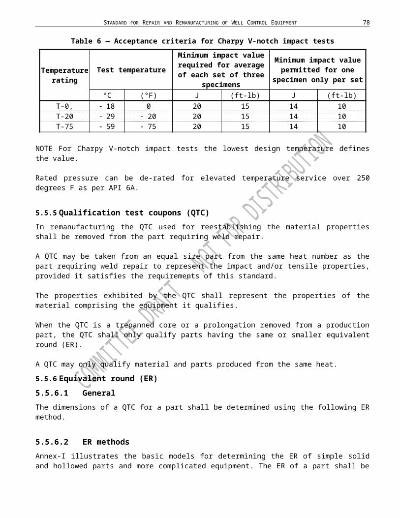
STANDARD FOR REPAIR AND REMANUFACTURING OF WELL CONTROL EQUIPMENT 78
A.1.2.2 Temperature ratings Minimum temperature is the lowest ambient temperature to which the equipment may be subjected. Maximum temperature is the highest temperature of the fluid that may flow through the equipment.
A.1.2.2.1 Temperature ratings for metallic materialsEquipment shall be repaired or remanufactured for metallic parts to operate within the temperature ranges shown in Table A3. Equipment from which traceability is lost or from which material properties cannot be reconstructed, shall be temperature classified to T-0.
Table A3 — Temperature ratings for metallic materials
Classification Operating range°C °F
T-75 59 to 121 75 to 250T-20 29 to 121 20 to 250T-0 18 to 121 0 to 250
T 350 -29 to 177 -20 to 350
NOTE Information on strength of materials at elevated temperatures is found in API 6A
A.1.2.2.2 Temperature ratings for non-metallic sealing materialsEquipment shall be repaired or remanufactured for wellbore elastomeric materials to operate within the temperature classifications of Table A4.
Table A4 — Temperature ratings for non-metallic sealing materials
Lower Limit
Upper Operating Limit
Upper extreme limit
(first digit)
(second digit)
(third digit)
Code Temperature Code Temperature Code TemperatureF C F C F C
A -15 -26 A 150 66 A 180 82B 0 -18 B 180 82 B 200 93C 10 -12 C 210 99 C 220 104D 20 -14 D 240 116 D 250 121E 30 -1 E 270 132 E 300 149F 40 4 F 300 149 F 350 177G Other Other G Other Other G Other Other
Example: Material "FDE" has a lower temperature rating of 40 degrees F , a continuouselevated temperature rating of 240 degrees F and an extreme temperature limit of 300 degrees F
All other elastomeric seals shall be designed to operate within the temperature ranges specified in the OEMs written specifications or OPD.
A.1.2.2.3 Wellbore elastomeric materialsThe purchaser shall provide the temperature range for which wellbore elastomeric materials must operate.
79 API SPECIFICATION 16AR
A.1.3 Outlet connectionsThe purchaser shall determine the number, location, size, pressure and temperature ratings for all outlet connections.
NOTE The pressure rating for the BOP or drilling spool is determined by the lowest pressure rating of all end or outlet connections.
Flanged end and outlet connections shall be in conformance to the dimensional requirements of API Specification 6A and API Specification 16A, prior to assembly and testing.
A.1.4 Equipment details/data bookOn request of the purchaser, and when specified in the contract, a data book shall be supplied, which shall meet or exceed the requirements for the Manufacturing Data Book (MDB) and / or Product History File (PHF), as listed in Annex B and Annex C.
STANDARD FOR REPAIR AND REMANUFACTURING OF WELL CONTROL EQUIPMENT 80
Annex B(Normative)
Manufacturing Data Book Requirements 222
The below mentioned document contents for the construction of the Manufacturing Data Book (MDB) shall be provided and recorded in order to provide the minimum traceability requirements for maintenance and remanufacturing of pressure control equipment manufactured under API 16A.
Manufacturing Data Book (MDB)
Document Contents Delivered to Client Maintained by Manufacturer
Purchase order number/sales order number √ √Date of Manufacturing √ √Serial Numbers of equipment and location √ √Assembly drawings showing:
Actual overall package dimensions Pressure rating End connection/outlet description Mass, Centre of gravity, List of materials for components defined
in API Specification 16A, section 8.5.1 and the location of their use.
√ √
Manufacturer's statement of compliance to current edition of API Specification 16A.
√ √
Design Verification Report Rated Working Pressure Temperature ratings Specified minimum yield strength (SMYS) Ultimate tensile strength (UTS) NACE Other specific customer requirements
√ √
Material Test Records (including the following): a) Certified Material test reports √ √
b) Chemical Analysis √ √
c) Tensile tests (QTC) or prolongation √ √
d) Impact tests (QTC as required) or prolongation as required
√ √
e) Hardness tests (QTC) or prolongation. √ √
f) NDE Personnel qualification records √May be difficult to get for older products, can be retrieved if brought in for repair at
original facility
√
81 API SPECIFICATION 16AR
Manufacturing Data Book (MDB) continued.
Document Contents Delivered to Client Maintained by Manufacturer
Material Specification Number √ √Welding Process Records:
Weld Data Sheet which includes:• Welder ID• Filler Metal• Welding consumable records• Heat and/or batch number• WPS #• Weld map• Weld inspection records• PWHT records• Sketch of local PWHT heater size location
and thermocouples location.
√ √
All remaining documentation required as defined in API 16A are kept at OEM / CEM facility for required length of time
√ √
NDE Records:
a) Surface NDE Records √ √
b) Full penetration fabrication √ √
c) Weld volumetric NDE records √ √
d) Repair weld NDE records √ √
Heat Treatment Records
a) Actual Temperature√ √
b) Actual times at temperature√ √
Third Party or Class Society Inspection Reports√ √
Test Report(s), Pressure Testing and Final Acceptance Testing a) Volumetric NDE Records / radiographic UT
Records√ √
b) Hydrostatic pressure test records √Limited scope and pressure test only
√
c) Critical dimensions (as defined by OEM / CEM)
√Limited scope and basic dimensions only
(height, weight, etc…)
√Critical dimensions
kept by OEM / CEM.
Final Acceptance Testing reports √ √
Certificate of Conformancea) includes the standard to which equipment is
certified to.
√ √

STANDARD FOR REPAIR AND REMANUFACTURING OF WELL CONTROL EQUIPMENT 82
Annex C(Normative)
Product History File Requirements 333
The below mentioned document contents for the construction of the Product History File (PHF) shall be provided and recorded in order to provide the minimum traceability requirements for maintenance and remanufacturing of pressure control equipment manufactured under API 16A.
Traceability shall be provided by the repairer / remanufacturer in the PHF for the parts being either original parts or non-original parts.
Product History File (PHF) Repair Only
Document Contents Delivered to Client Maintained by Manufacturer
Manufacturing Data Book √ √Serial Numbers of equipment and location √ √Design Verification Report √
Still covered by original design verification , however design verification
reports remain proprietary to OEM or CEM
√
Third Party or Class Society Inspection Reports√ √
Test Report(s), Pressure Testing and Final Acceptance Testing a) Volumetric NDE Records / radiographic UT
Records√ √
b) Hydrostatic pressure test records √Limited scope and pressure test only
√
c) Critical dimensions (as defined by OEM) √Limited scope and basic dimensions only
(height, weight, etc…)
√
Final Acceptance Testing reports √ √
Certificate of Conformancea) includes the standard to which equipment is
certified to.
√ √

83 API SPECIFICATION 16AR
Product History File (PHF) Repair and RemanufacturingManufacturing Data Book (if available)
√ √
Serial Numbers of equipment and location √ √
Design Verification Report (if available)
√Repair facility will be required to
ensure that all design verification is compliant with API 16A.
√
PMI Test √ √
Material Specification Number √ √
Welding Process Records (if applicable)Weld Data Sheet which includes:• Welder ID• Filler Metal• Welding consumable records• Heat and/or batch number• WPS #• Weld map• Weld inspection records• PWHT records• Sketch of local PWHT heater size location
and thermocouples location.
√ √
All remaining documentation required as defined in API 16A are kept at OEM / CEM facility for required length of time
√ √
NDE Records √ √
Heat Treatment Records (if applicable)√ √
Third Party or Class Society Inspection Reports√ √
Test Report(s), Pressure Testing and Final Acceptance Testing
√ √
a) Volumetric NDE Records / radiographic UT Records
√ √
b) Hydrostatic pressure test records √Limited scope and pressure test only
√
c) Critical dimensions (as defined by OEM) √Limited scope and basic dimensions
only (height, weight, etc…)
√
Statement of Compatibilitya) includes the standard to which equipment
is certified to.
√ √

STANDARD FOR REPAIR AND REMANUFACTURING OF WELL CONTROL EQUIPMENT 84
Annex D(Normative)
Failure reporting 444
D.1 Owner Responsibility
The equipment owner of blowout prevention equipment shall provide a failure notification to the equipment manufacturer. The manufacturer shall, on request of the equipment owner, provide a failure report / of any malfunction or failure.
The failure report shall include the following:
― as much information as possible on the operating conditions that existed at the time of the malfunction or failure;
― an accurate a description as possible of the malfunction or failure;
― any operating history of the drill through equipment leading up to the malfunction or failure (e.g. field repair, modifications made to the drill through equipment, etc.).
The CEM or OEM shall respond to receiving the failure report and provide a timeline to provide failure resolution.
D.2 Manufacturer’s Responsibility
D.2.1 Manufacturer’s Internal Responsibility
All failures experienced with drill through equipment from the owner or operator shall be formally communicated to the individual or group within the CEM or OEM organization responsible for the design and specification documents.
The CEM or OEM shall have a written procedure that describes forms and procedures for making this type of communication, and shall maintain records of progressive design, material changes, or other corrective actions taken for each model and size of blowout prevention equipment.
D.2.2 Manufacturer’s External Responsibility
All failures experienced with drill through equipment shall be reported in writing to each and every equipment owner of the blowout prevention equipment within three weeks after the occurrence.
The CEM or OEM shall communicate any design changes resulting from a malfunction or failure history to every equipment owner using the affected equipment. That notice shall be within 14 days after the design change.

85 API SPECIFICATION 16AR
Annex E(Normative)
Design ownership 555
If any alterations to the original design and/or assembled equipment or component part are made by anyone other than the OEM, the assembly, part, or component shall not be considered an OEM product. The party that performs these alterations shall be then designated as the Current Equipment Manufacturer (CEM).
Used pressure control equipment
All parts in assembly are in conformance with the product definition for the
assembled system, subassembly or product.
Repair / replacement parts
Remanufacture(hot work and / or
machining)
OEM/CEM controls the specification for the assembled system,
subassembly or product after repair and will provide a COC
The Owner / User controls the specification of the hybrid system, unless one of the suppliers of parts adopts the
assembled system, subassembly or product as CEM and will provide a COC.
Part is supported by a current verified and validated product
definition
Yes
Yes
No
No
Part is in conformance with remanufacturers verified and validated
product definition
Yes
No
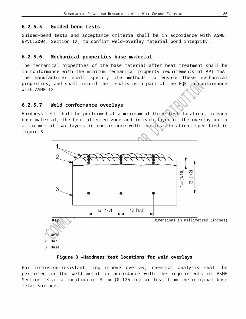
Company Registration No.: Insert Registration # Certificate No.: ABC-14-0001
STANDARD FOR REPAIR AND REMANUFACTURING OF WELL CONTROL EQUIPMENT 86
Annex F(Informative)
Minimum requirements for Certificate Of Conformance (COC)
NOTE This example contains the minimum requirements for the certificate of conformance in order to provide good traceability of the equipment through field life.
Example
Company Logo
CERTIFICATE OF CONFORMANCE
Certificate No. :
Customer :
Customer Reference No.:
Date of Remanufacture:
Customer Purchase Order:
Work Order No.:
A. Assurance:This is to confirm that the drill through equipment remanufactured per the above purchase order and as listed below have been inspected and/or remanufactured and maintained in accordance with the following:
1. API Spec.16AR “Specification for Drill-through Equipment Repair and Remanufacture”, 1 st Edition, RSL level 1, 2 or 3
2. Companies current understanding of implementation and interpretation of Jurisdictional regulations listed here:
a. …………..b. …………..
In addition, the following additional standard(s) have been used in support of the repair and remanufacture of the equipment listed on this certificate:
API Spec16A “Specification for Drill-through Equipment”, latest Edition …………… ……………
Company NameCompany Address
Company telephone number

87 API SPECIFICATION 16AR
Controlled Document No. Revision Date/Level Page 1 of 2

STANDARD FOR REPAIR AND REMANUFACTURING OF WELL CONTROL EQUIPMENT 88
B. The certification is related to the following operational limitation:
Maximum Working Pressure:
Design Temperature (minimum to maximum):
Sour Service according to NACE MR0175 / ISO 15156: Yes / No
Remanufacturing Specification Level (RSL)
Other limitation:
C. List of inspected equipment:
Item Assembly or Part No. Qty. Description Serial Number(s)
1
2
3
D. Comments: It is the responsibility of the owner to ensure that risk analysis is considered and carried out prior to every
operation including subject equipment when evaluating the risk situation. All documentation in support of the above listed products is retained on file by the Company for a minimum
of 10 years for repair / remanufacture. All documents and inspection reports to support this certificate of conformance have been verified to the
best of my knowledge to be true and correct. All documents and inspection reports to support this certificate of conformance have been added to the
Product History File. All documents and inspection reports to support this certificate of conformance shall be added and
maintained by the Owner in the Product History File.
E. Conditions Non-metallic sealing material shall be capable of functioning at specified design temperature and at
retained fluid rating, Sour Service, NACE MR0175 / ISO 15156.
Certificate of Conformance Approval
Signature Signature
Name: Name:Title: Title:
Company disclaimer or Quality disclaimer if so desired by the organization.

89 API SPECIFICATION 16AR
Controlled Document No. Revision Date/Level Page 2 of 2
STANDARD FOR REPAIR AND REMANUFACTURING OF WELL CONTROL EQUIPMENT 90
Annex G(Informative)
666Recommended weld preparation design dimensions
NOTE Recommended weld preparation designs and dimensions shown in this annex should be considered for joining parts through welding.
Dimensions in millimetres (inches) unless otherwise indicated
a) V-groove
b) U-groove
c) Heavy-wall V-groove

91 API SPECIFICATION 16AR
Keya Maximum misalignment.
Figure G.1 — Typical weld grooves for pipe butt joints
Dimensions in millimetres (inches) unless otherwise indicated
Keya Maximum misalignment (unless removed by machining).b Remove to sound metal by machining.c Maximum misalignment.d Backing shall be removed. Material shall be compatible with base material.
Figure G2 — Typical attachment welds

STANDARD FOR REPAIR AND REMANUFACTURING OF WELL CONTROL EQUIPMENT 92
Dimensions in millimetres (inches) unless otherwise indicated
Keya Ratio of d1 to D2 shall not exceed 1,5:1.b Depth required to maintain a maximum of 1,5:1 depth, d1, to diameter, D2, ratio.
Figure G3 — Typical repair welds
Key1 side2 enda Original area.
Figure G4 — Repairs

93 API SPECIFICATION 16AR
Annex H(Normative)
Qualification of heat-treating equipment
H.1 GeneralAll heat treatment of parts and QTCs shall be performed with equipment meeting the requirements of this annex.
H.2 Temperature toleranceThe temperature at any point in the working zone shall not vary by more than 14°C ( 25 °F) from the furnace set-point temperature after the furnace working zone has been brought up to temperature (SAE AMS 2750E, Class 5 or better). Furnaces which are used for tempering, aging and/or stress-relieving shall not vary by more than 8 °C ( 15 °F) from the furnace set-point temperature after the furnace working zone has been brought up to temperature.
H.3 Furnace calibrationH.3.1 GeneralHeat treatment of production parts shall be performed with heat-treating equipment that has been calibrated and surveyed.
H.3.2 RecordsRecords of furnace calibration and surveys shall be maintained for a period not less than three (3) years.
H.3.3 Temperature survey method for calibration of batch-type furnacesA temperature survey within the furnace working zone(s) shall be performed on each furnace at the maximum and minimum temperatures for which each furnace is to be used.
A minimum of nine thermocouple test locations shall be used for all furnaces having a working zone greater than 0.3 m3 (10 ft3).
For each 3,5 m3 (125 ft3) of furnace working zone surveyed, at least one thermocouple test location shall be used, up to a maximum of 40 thermocouples. See Figures H.1 and H.2 for examples of thermocouple locations.
For furnaces having a working zone less than 0.3 m3 (10 ft3), the temperature survey may be made with a minimum of three thermocouples located either at the front, center and rear, or at the top, center and bottom of the furnace working zone.
After insertion of the temperature-sensing devices, readings shall be taken at least once every 3 minutes to determine when the temperature of the furnace working zone approaches the bottom of the temperature range being surveyed.
Once the furnace temperature has reached the set-point temperature, the temperature of all test locations shall be recorded at 2-min intervals, maximum, for at least 10 minutes. Then readings shall be taken at 5-min intervals, maximum, for sufficient time (at least 30 minutes) to determine the recurrent temperature pattern of the furnace working zone.
Before the furnace set-point temperature is reached, none of the temperature readings shall exceed the set-point temperature by more than 14 ºC (25 ºF).
After the furnace control set-point temperature is reached, no temperature reading shall vary beyond the limits specified. The temperatures within each furnace shall be surveyed within one year prior to use of the furnace for heat treatment.
When a furnace is repaired or rebuilt, a new temperature survey shall be carried out before the furnace is used for heat treatment, subject to the following. 1) Repairs that return the furnace to the condition it was in at the time of the last furnace survey and calibration or
repairs that do not affect the temperature tolerance of the furnace shall not require a new temperature survey and calibration.

STANDARD FOR REPAIR AND REMANUFACTURING OF WELL CONTROL EQUIPMENT 94
2) The SAE AMS 2750 sections on furnace modifications and furnace repairs shall be used to determine whether a new furnace survey is required.
3) All furnace repairs and modifications shall be documented and the responsible Quality Assurance organization shall make determination whether an additional furnace survey and calibration is required based on the repairs or modifications in accordance with AMS 2750.
a) Top view b) Side view
Figure H.1 — Thermocouple locations — Rectangular furnace (working zone)
a) Side view b) Top view
Figure H.2 — Thermocouple locations — Cylindrical furnace (working zone)

95 API SPECIFICATION 16AR
The scenarios in this annex are merely examples for illustration purposes only. Each company should develop its own approach. They are not to be considered exclusive or exhaustive in nature.
H.3.4 Continuous-type furnaces methodFurnaces used for continuous heat treatment shall be calibrated in accordance with procedures specified in SAE AMS-H-6875B.
H.4 InstrumentsH.4.1 GeneralAutomatic controlling and recording instruments shall be used.Thermocouples shall be located in the furnace working zone(s) and protected from furnace atmospheres by means of suitable protective devices.
H.4.2 AccuracyThe controlling and recording instruments used for the heat-treatment processes shall be accurate to 1 % of their full-scale range.
H.4.3 CalibrationTemperature-controlling and -recording instruments shall be calibrated at least once every three months.Equipment used to calibrate the production equipment shall be accurate to 0.25 % of full-scale range.
When a furnace is repaired or rebuilt, a new temperature survey shall be carried out before the furnace is used for heat treatment, subject to the following.
Repairs that return the furnace to the condition it was in at the time of the last furnace survey and calibration or repairs that do not affect the temperature tolerance of the furnace shall not require a new temperature survey and calibration.
The SAE AMS 2750 sections on furnace modifications and furnace repairs shall be used to determine whether a new furnace survey is required.
All furnace repairs and modifications shall be documented and the responsible Quality Assurance organization shall make determination whether an additional furnace survey and calibration is required based on the repairs or modifications in accordance with AMS 2750.

STANDARD FOR REPAIR AND REMANUFACTURING OF WELL CONTROL EQUIPMENT 96
Annex I(Normative)
Equivalent Rounds (ER) models777
This annex illustrates the basic models for determining the ER of simple solid and hollowed parts and more complicated equipment. The ER of an existing part shall be determined using the actual dimensions of the part in the “as-heat-treated” condition. Test coupons are only required to be taken from the part when traceability has been lost and base material properties must be re-established.
When L is less than T, consider section as a plate of L thickness. Area inside dashed lines is 1/4 T envelope for test specimen removal.
When L is less than D, consider as a plate of T thickness
Figure I.1—Simple geometric equivalent rounds (ER) sections/shapes having length L
a. Where T is the thickness when the component is heat-treated, use the larger of the two indicated dimensions.
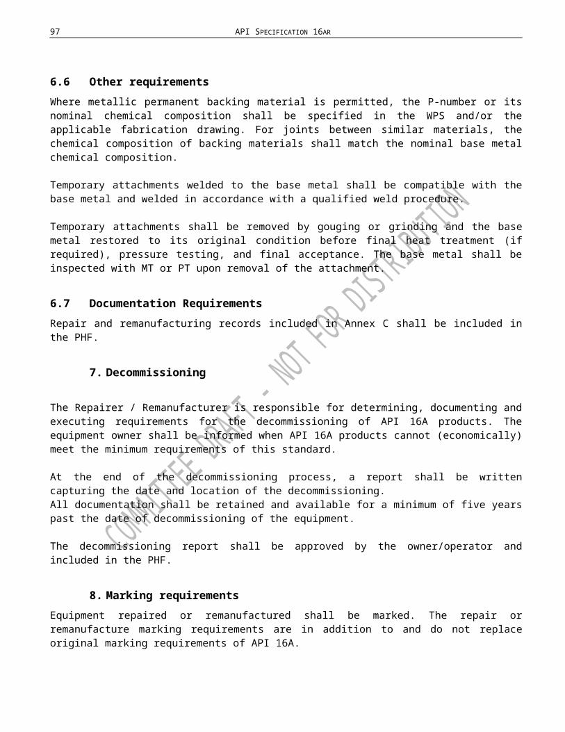
97 API SPECIFICATION 16AR
When all internal and external surfaces during heat treatment are within 13 mm (1/2 in) of the final surfaces, ER 1/4 T.
When all internal and external surfaces during heat treatment are not within 13 mm (0.5 in) of the final surfaces, then ER 2 T. On multi-flanged components, T shall be the thickness of the thickest flange.
Figure I.2 — Complex-shaped components
b. Envelope for test specimen removal.
.Figure I.3 — Equivalent round models
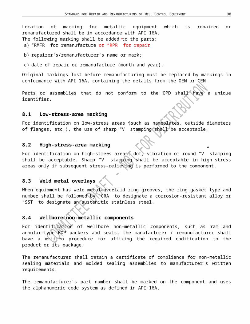
STANDARD FOR REPAIR AND REMANUFACTURING OF WELL CONTROL EQUIPMENT 98
Annex J(Normative)
Replacement parts 888
In order to assess the remanufacturing specification level (RSL) for replacement parts, the below shown process flow diagram shall be used.
All parts meet a current product definition
Not all parts meet current product
definition. Parts have partial traceability
RSL-1RSL-2RSL-3
Remanufactured / replacement partsAll parts shall meet or exceed the requirements of API-16A specification.
Part is not in conformance with the requirements of the API 16AR standard.
Design verification and validation completed
Replacement or Remanufactured parts meet or exceed the full API 16A specification, including all design verification and validation, and may be used in an assembly repaired as per 16AR.
API 16A + QMS Requirements in 16AR1) Design documentation (verification)2) Design review3) Design validation
No
Yes
Not all parts meet current product
definition. All parts have full traceability
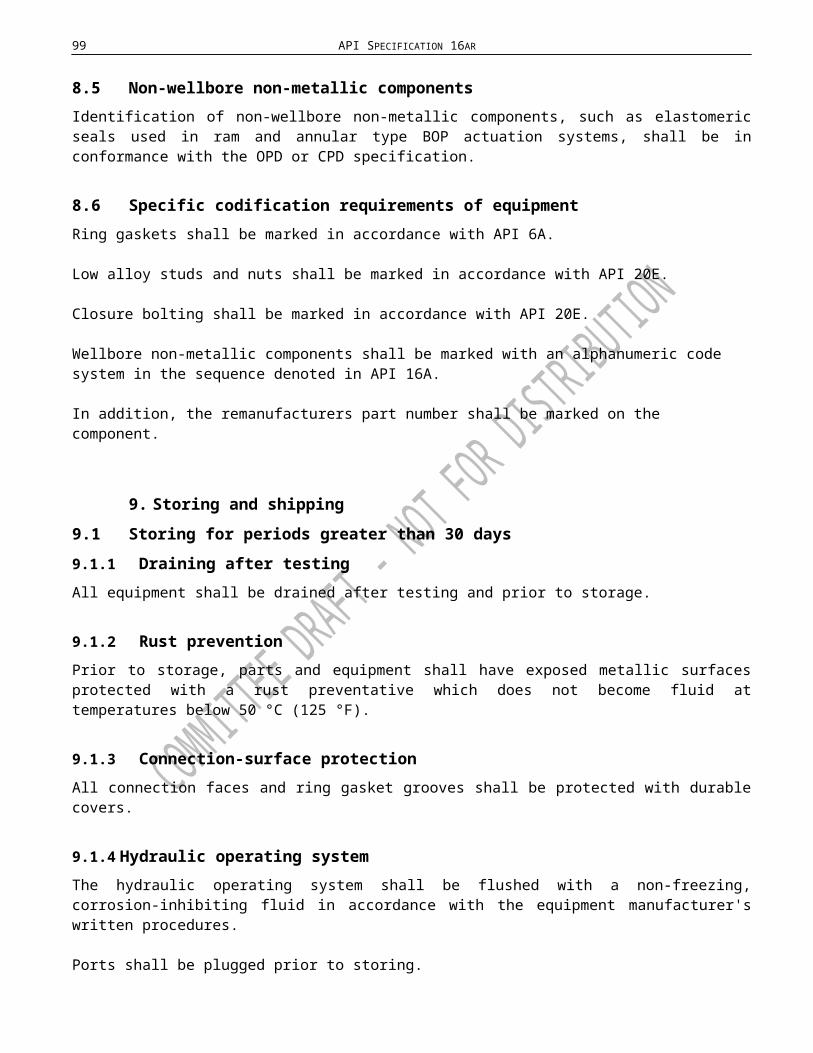
99 API SPECIFICATION 16AR
Annex K(Normative)
Location of Charpy V-notch impact tests for weld qualification 999
When impact testing is required the testing shall be performed in accordance with ASTM A370 using the Charpy V-notch technique. Results of testing in the weld and HAZ shall meet the minimum requirements of the base material, for both average and minimum toughness requirements.
If any one of the three specimens falls below the minimum allowed toughness requirement, then two additional Charpy test specimens will be required from that area and both shall be at or above the minimum toughness requirement. Records of results shall become part of the PQR.
The amount and of Charpy V-notch impact test specimen shall be in accordance with Figure K.1 following the sampling requirements in relation with the material thickness and qualification weld type:
a. Less or equal to 20 mm (0.8 inch) – Charpy specimens shall be taken from the external surface (within 2mm from the surface), subject to the requirements for multi-process and double sided welds.
b. Greater than 20 mm (0.8 inch) to less or equal to 40 mm (1.6 inch) – Charpy specimens shall be taken from the external and internal surface (within 2mm from both surfaces), subject to the requirements for multi-process and double sided welds.
c. Greater than 40 mm (1.6 inch) – Charpy specimens shall be taken from the external and internal surfaces within 2mm (0.1 inch) from both surfaces and from the mid wall position, subject to the requirements for multi-process and double sided welds.
When impact testing is required, sets of three test specimens shall be removed from the weld, fusion-line, and fusion-line (FL) + 2 mm (0.1 inch).
When the welding process heat input is greater than 2 kJ/mm (50 kJ/in), an additional set of Charpy test specimens shall be removed from the fusion-line (FL) +5 mm (0.2 inch).
If multiple welding processes are used to produce the weldment, the weld metal and appropriate HAZ test specimens shall be removed for each welding process.
On double sided welds, weld metal from the root region containing fully melted individual or continuous tack welds shall also be Charpy tested.

STANDARD FOR REPAIR AND REMANUFACTURING OF WELL CONTROL EQUIPMENT 100
t ≤ 20 mm (0.8 inch)
t > 20 ≤ 40 mm (> 0.8 < 1.6 inch)
t > 40 mm (1.6 inch)
Legend:a = On weld centerb = On fusion line (FL)c = In Heat Affected Zone (HAZ) , FL + 2 mm (0.1 inch)d = In Heat Affected Zone (HAZ), FL + 5 mm (0.2 inch)
a b c d
a b c d
d
ba c dba c d
cba
d
a b c d
ba c d
cba d
a b c d
cba d
ba c d
a b c d
a b c
t
t
t
FL + 2 mm
2 mm (0.1 inch)
2 mm (0.1 inch)
2 mm (0.1 inch) 2 mm (0.1 inch)
2 mm (0.1 inch)
2 mm (0.1 inch) 2 mm (0.1 inch)
2 mm (0.1 inch)
Figure K.1 — Location of Charpy V-notch impact test

101 API SPECIFICATION 16AR
Bibliography
[1] API Bulletin 6AF, Capabilities of API flanges under combinations of load
[2] API Specification Q2: Specification for Quality Management System Requirements for Service Supply Organizations for the Petroleum, Petrochemical and Natural Gas Industry
[3] ASME Boiler and Pressure Vessel Code Section VIII, Division 1, Appendix 4, Rounded Indication Charts Acceptance Standard for Radiographically Determined Rounded Indications in Welds
[4] ASME Boiler and Pressure Vessel Code Section VIII, Division 2, Pressure Vessel — Alternate Rules, Appendix 4, Design Based on Stress Analysis
[5] ASME Boiler and Pressure Vessel Code Section VIII, Division 2, Pressure Vessel — Alternate Rules, Appendix 6, Experimental Stress Analysis
[6] ASTM A 193, Specification for Alloy Steel and Stainless Steel Bolting Materials for High Temperature Service
[7] ASTM A 320, Specification for Alloy Steel Bolting Materials for Low Temperature Service
[8] ASTM A 453, Specification for Bolting Materials, High Temperature, 50 to 120 ksi Yield Strength, with Expansion Coefficients Comparable to Austenitic Steels
[9] ASTM E 747, Standard Practice for Design, Manufacture, and Material Grouping Classification of Wire Image
[10] AWS QC1 Standard for AWS Certification of Welding Inspectors

Additional copies are available through Global Engineering Documents at (800) 854-7179 or (303) 397-7956Information about API Publications, Programs and Services is available on the World Wide Web at http://www.api.org
Product No: G6HT01


