Gonstead Pelvic Analysis Click to label each segment Would like have prompts (ex. “click on L1,...
11
Gonstead Pelvic Analysis • Click to label each segment • Would like have prompts (ex. “click on L1, click on L2”) L1 L2 L3 L4 L5
-
Upload
jimmy-etherington -
Category
Documents
-
view
250 -
download
5
Transcript of Gonstead Pelvic Analysis Click to label each segment Would like have prompts (ex. “click on L1,...

Gonstead Pelvic
Analysis• Click to label each
segment• Would like have
prompts (ex. “click on L1, click on L2”)
L1
L2
L3
L4
L5

Gonstead Pelvic
Analysis• Click highest point
on right femur head (have computer place dot there)
• Click on the highest point of the left femur head (place dot)
• Draw line connecting dots – “femoral head line”
L1
L2
L3
L4
L5
. .

Gonstead Pelvic
Analysis• Click the highest point on
right iliac crest (have computer place dot there)
• Click the lowest point on right ischial tuberosity (have computer place dot there)
• Click the highest point on left iliac crest (have computer place dot there)
• Click the lowest point on left ischial tuberosity (have computer place dot there)
• Would like to be able to click and drag the dots to adjust their position and/or select the dot and use the arrow keys to “nudge” it into the desired position
L1
L2
L3
L4
L5
. .
. .
. .

Gonstead Pelvic
Analysis• All lines “flying in”
are constructed parallel to the femoral head line.
L1
L2
L3
L4
L5
. .
. .
. .
Gonstead Pelvic
Analysis• Need to measure distance
between the iliac crest line and ischial tuberosity line 90 degrees/ perpendicular to the femoral head line, not from point to point, and not true vertical.
• Complete for left and right side
• Measurements ( must be mm) need to be displayed on screen (if possible just caudal to the femur head dots)
• Do not need to display these vertical measurement lines
• (having the computer automatically compute the measurement would be a plus)
L1
L2
L3
L4
L5
. .
. .
. .
163 168
Gonstead Pelvic
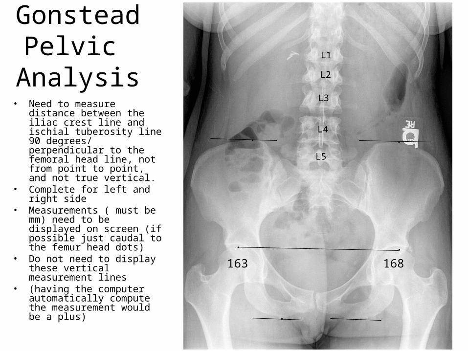
Analysis• Place dot on S2
tubercle (or S1if preferred/ visualized).
• Place a dot in the center of the pubic symphysis.
L1
L2
L3
L4
L5
. .
. .
. .
163 168
.
.

Gonstead Pelvic
Analysis• Draw line perpendicular
to the FHL through the S1 tubercle to be displayed adjacent to the symphysis pubis
• Measure between pubic symphysis dot and resultant line (mm); display just caudal to the pubic symphysis dot.
• (having the computer automatically compute the measurement would be a plus)
L1
L2
L3
L4
L5
. .
. .
. .
163 168
.
.
2

Gonstead Pelvic
Analysis• Place a dot at the
lateral aspect of each S1 facet base
• Draw a connecting line, the sacral base line
L1
L2
L3
L4
L5
. .
. .
. .
163 168
.
.
2
. .
Gonstead Pelvic
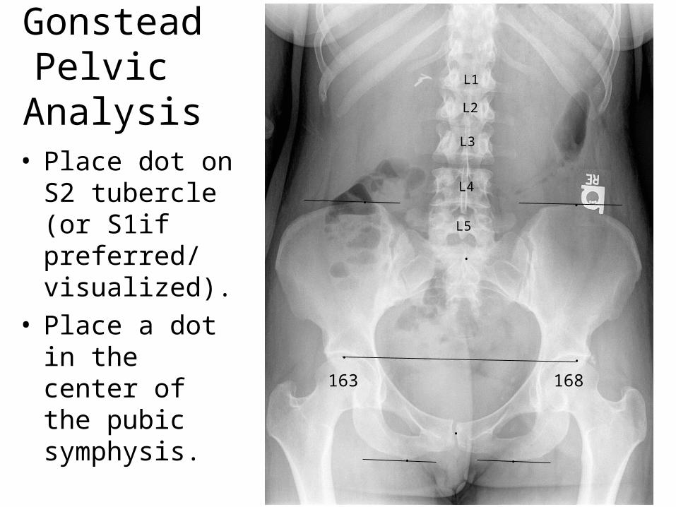
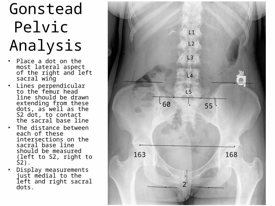
Analysis• Place a dot on the most
lateral aspect of the right and left sacral wing
• Lines perpendicular to the femur head line should be drawn extending from these dots, as well as the S2 dot, to contact the sacral base line
• The distance between each of these intersections on the sacral base line should be measured (left to S2, right to S2).
• Display measurements just medial to the left and right sacral dots.
L1
L2
L3
L4
L5
. .
. .
. .
163 168
.
.
2
. .. .60 55

Gonstead Pelvic
AnalysisL1
L2
L3
L4
L5
. .
. .
. .
163 168
.
.
2
. .. .60 55
3MD
• Calculate the Measured Deficiency (m.d.)
– Extend a line horizontally from most superior aspect of the higher of the two femur heads to overly the lower femur head. This line would be best represented by a short line above the lower femur head.
– Measure the true vertical distance from the most superior aspect of the lower femur head to the line (from the previously placed dot to the line).
– Record the measurement adjacent to the end of the horizontal line with the label “MD” (as pictured)

Gonstead Pelvic
AnalysisL1
L2
L3
L4
L5
. .
. .
. .
163 168
.
.
2
. .. .60 55
3MD
• Place a dot on the most lateral aspect of the right iliac wing
• Place a dot on the most medial aspect of the posterior superior iliac spine
• Lines perpendicular to the femur head line should be drawn through these dots
• Measure perpendicular distance between the resultant lines
• Display measurement just medial to the lateral dot
• Repeat for the left side
. . ..89 83