GOM Verification Of Finite Element Simulations
70
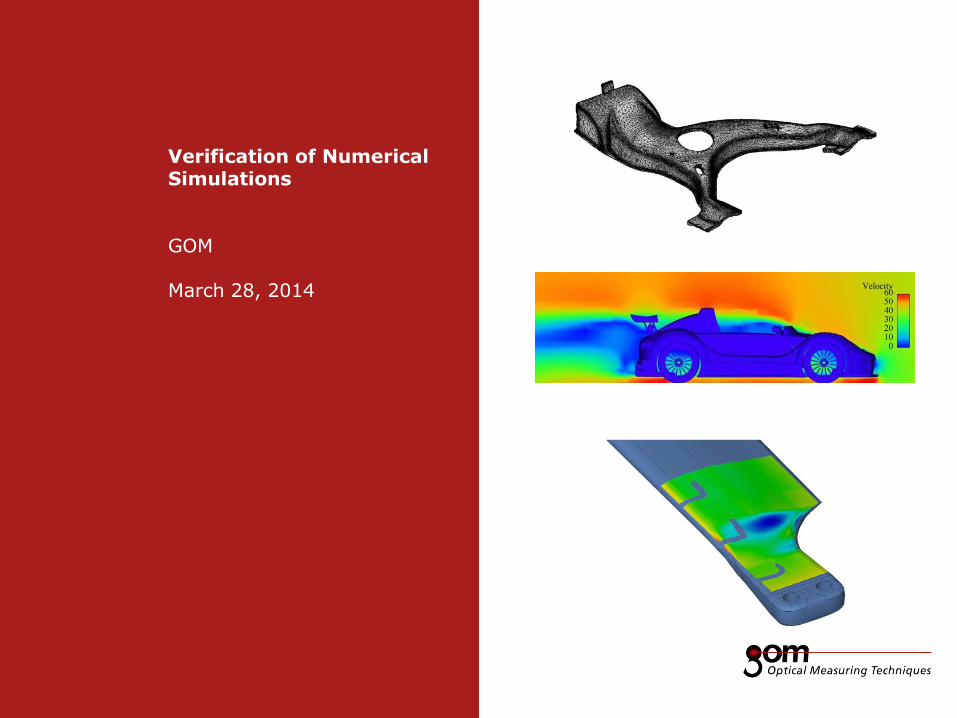
Verification of Numerical Simulations GOM March 28, 2014
-
Upload
trilionqualitysystems -
Category
Software
-
view
332 -
download
2
Transcript of GOM Verification Of Finite Element Simulations
Frame 1
Frame 1
Underline 1
Underline 2
Underline 1
Underline 2
Frame 2
Frame 2 Frame 1
Column 1 Column 2
Column 3 Column 1 Column 2
Content
Content
Left Line Title
Upper Line Title
Right Line Title
Verification of Numerical Simulations GOM March 28, 2014
2-Frame Setup / Frame 2 2-Frame Setup / Frame 1
3-Frame Setup / Frame 1 3-Frame Setup / Frame 2 3-Frame Setup / Frame 3
Frame 1
Frame 1
Underline 1
Underline 2
Underline 1
Underline 2
Page 2 Verification of Numerical Simulations GOM
Frame 2
Frame 2 Frame 1
Column 1 Column 2
Column 3 Column 1 Column 2
Content
Content
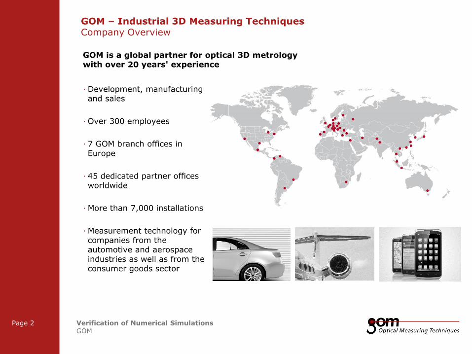
GOM – Industrial 3D Measuring Techniques Company Overview
· Development, manufacturing and sales
· Over 300 employees
· 7 GOM branch offices in Europe
· 45 dedicated partner offices worldwide
· More than 7,000 installations
· Measurement technology for companies from the automotive and aerospace industries as well as from the consumer goods sector
GOM is a global partner for optical 3D metrology with over 20 years' experience

2-Frame Setup / Frame 2 2-Frame Setup / Frame 1
3-Frame Setup / Frame 1 3-Frame Setup / Frame 2 3-Frame Setup / Frame 3
Frame 1
Frame 1
Underline 1
Underline 2
Underline 1
Underline 2
Page 3 Verification of Numerical Simulations GOM
Frame 2
Frame 2 Frame 1
Column 1 Column 2
Column 3 Column 1 Column 2
Content
Content
GOM Customers (Extract)
Automobile manufacturers · Audi D
· Avtovaz RU
· Bentley UK
· BMW AT, D, UK
· Chrysler USA
· Daimler D
· Fiat IT
· Ford BE, D, UK, USA, BR
· Freightliner USA
· General Motors AU, AT, BR, USA
· Honda CN, JP, USA
· Hyundai KR
· Isuzu JP
· Jaguar UK
· Kia KR
· Land Rover UK
· McLaren UK
· Modenas MY
· NAZA MY
· Nissan JP, UK, USA
· Opel D
· Porsche D
· PSA FR
· Renault FR, ES, TR
· Seat ES
· Skoda CZ
· Subaru JP
· Suzuki CN
· Tata Motors Limited IN
· Toyota D, J, TR, USA, CA
· Volkswagen CN, D, MX, PL
· Volvo SE
· Temsa TR
Automotive suppliers · Autopal CZ
· Batz ES
· Bertone IT
· Bertrandt D
· Bosch D, CH
· Bridgestone JP
· Carcoustics LI
· DAAZ RU
· Delphi JP
· Faurecia D, FR
· FES D
· Goodyear USA
· Hella Leuchtensysteme D
· IAV D
· Italdesign-Giugiaro IT
· Kautex Textron D
· Läpple D
· LUK D
· Magna CA, AT
· Mahle D
· Matador SK
· Matrici ES
· Metalbages ES
· Michelin FR
· Montupet FR
· Nothelfer DE
· OLHO Technik DE
· Pierburg Kolbenschmidt AG, D
· Pininfarina IT
· Solvay BE
· ThyssenKrupp D
Aerospace · Airbus D
· Airforce Research Laboratories USA
· Aselsan TR
· Boeing USA
· Cessna USA
· Chrom Alloy USA, TH
· DLR D
· EADS D, FR
· ELBAR SULZER NL
· Eurocopter D
· Federal Aviation Administration USA
· FOI SE
· Gorbynov Aviation Production RU
· Honeywell IE, USA
· Howmet UK, USA, JP
· IMA Dresden DE
· IMPO RU
· Lockhead Martin USA
· MTU D
· NASA USA
· Northrop Grumman Systems Corp. USA
· ONERA FR
· Pratt & Whitney USA, NO
· RollsRoyce UK, USA
· Saturn RU
· Snecma Propulsion Solide FR
· Solar Turbines USA
· Triumph USA
· Turbine Services USA
· Vulcan Air IT
· VZLÚ CZ
2-Frame Setup / Frame 2 2-Frame Setup / Frame 1
3-Frame Setup / Frame 1 3-Frame Setup / Frame 2 3-Frame Setup / Frame 3
Frame 1
Frame 1
Underline 1
Underline 2
Underline 1
Underline 2
Page 4 Verification of Numerical Simulations GOM
Frame 2
Frame 2 Frame 1
Column 1 Column 2
Column 3 Column 1 Column 2
Content
Content
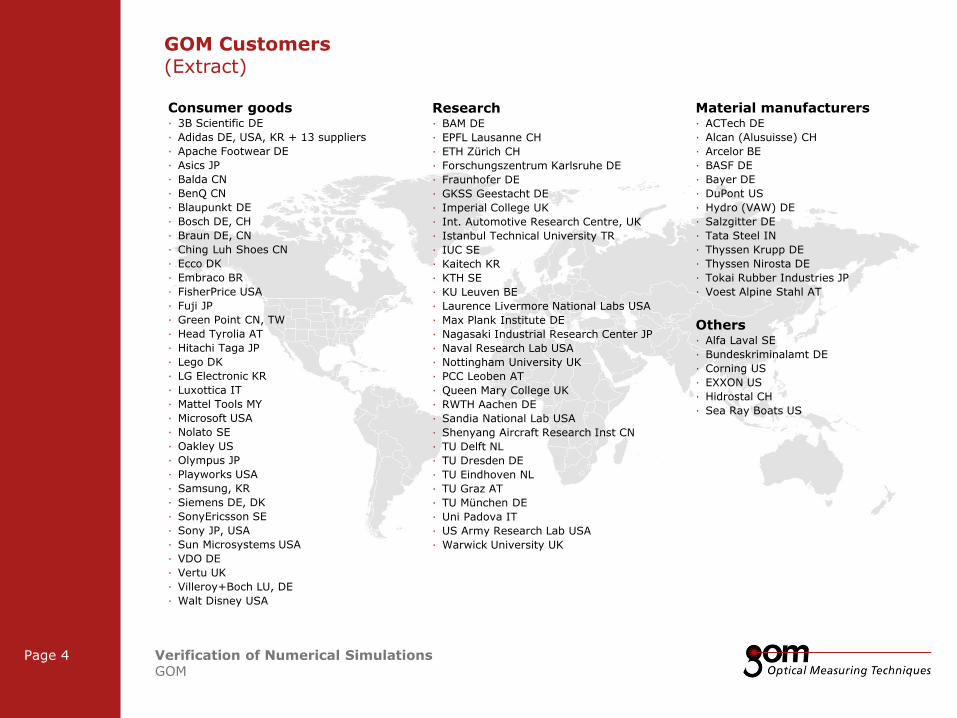
Material manufacturers · ACTech DE
· Alcan (Alusuisse) CH
· Arcelor BE
· BASF DE
· Bayer DE
· DuPont US
· Hydro (VAW) DE
· Salzgitter DE
· Tata Steel IN
· Thyssen Krupp DE
· Thyssen Nirosta DE
· Tokai Rubber Industries JP
· Voest Alpine Stahl AT
Others · Alfa Laval SE
· Bundeskriminalamt DE
· Corning US
· EXXON US
· Hidrostal CH
· Sea Ray Boats US
GOM Customers (Extract)
Consumer goods · 3B Scientific DE
· Adidas DE, USA, KR + 13 suppliers
· Apache Footwear DE
· Asics JP
· Balda CN
· BenQ CN
· Blaupunkt DE
· Bosch DE, CH
· Braun DE, CN
· Ching Luh Shoes CN
· Ecco DK
· Embraco BR
· FisherPrice USA
· Fuji JP
· Green Point CN, TW
· Head Tyrolia AT
· Hitachi Taga JP
· Lego DK
· LG Electronic KR
· Luxottica IT
· Mattel Tools MY
· Microsoft USA
· Nolato SE
· Oakley US
· Olympus JP
· Playworks USA
· Samsung, KR
· Siemens DE, DK
· SonyEricsson SE
· Sony JP, USA
· Sun Microsystems USA
· VDO DE
· Vertu UK
· Villeroy+Boch LU, DE
· Walt Disney USA
Research · BAM DE
· EPFL Lausanne CH
· ETH Zürich CH
· Forschungszentrum Karlsruhe DE
· Fraunhofer DE
· GKSS Geestacht DE
· Imperial College UK
· Int. Automotive Research Centre, UK
· Istanbul Technical University TR
· IUC SE
· Kaitech KR
· KTH SE
· KU Leuven BE
· Laurence Livermore National Labs USA
· Max Plank Institute DE
· Nagasaki Industrial Research Center JP
· Naval Research Lab USA
· Nottingham University UK
· PCC Leoben AT
· Queen Mary College UK
· RWTH Aachen DE
· Sandia National Lab USA
· Shenyang Aircraft Research Inst CN
· TU Delft NL
· TU Dresden DE
· TU Eindhoven NL
· TU Graz AT
· TU München DE
· Uni Padova IT
· US Army Research Lab USA
· Warwick University UK
2-Frame Setup / Frame 2 2-Frame Setup / Frame 1
3-Frame Setup / Frame 1 3-Frame Setup / Frame 2 3-Frame Setup / Frame 3
Frame 1
Frame 1
Underline 1
Underline 2
Underline 1
Underline 2
Page 5 Verification of Numerical Simulations GOM
Frame 2
Frame 2 Frame 1
Column 1 Column 2
Column 3 Column 1 Column 2
Content
Content
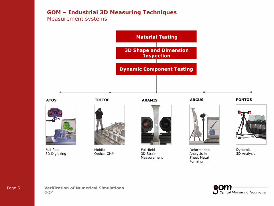
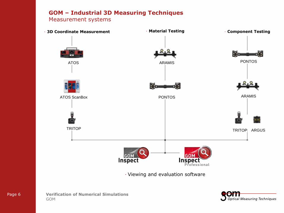
GOM – Industrial 3D Measuring Techniques Measurement systems
Full-field
3D Digitizing
ATOS
3D Shape and Dimension Inspection
Material Testing
Dynamic Component Testing
Full-field
3D Strain Measurement
ARAMIS
Deformation Analysis in Sheet Metal Forming
ARGUS
Mobile
Optical CMM
TRITOP
Dynamic
3D Analysis
PONTOS
2-Frame Setup / Frame 2 2-Frame Setup / Frame 1
3-Frame Setup / Frame 1 3-Frame Setup / Frame 2 3-Frame Setup / Frame 3
Frame 1
Frame 1
Underline 1
Underline 2
Underline 1
Underline 2
Page 6 Verification of Numerical Simulations GOM
Frame 2
Frame 2 Frame 1
Column 1 Column 2
Column 3 Column 1 Column 2
Content
Content
GOM – Industrial 3D Measuring Techniques Measurement systems
· Material Testing · 3D Coordinate Measurement · Component Testing
ATOS
ATOS ScanBox
TRITOP
ARAMIS
PONTOS
PONTOS
ARAMIS
TRITOP ARGUS
· Viewing and evaluation software
2-Frame Setup / Frame 2 2-Frame Setup / Frame 1
3-Frame Setup / Frame 1 3-Frame Setup / Frame 2 3-Frame Setup / Frame 3
Frame 1
Frame 1
Underline 1
Underline 2
Underline 1
Underline 2
Page 7 Verification of Numerical Simulations GOM
Frame 2
Frame 2 Frame 1
Column 1 Column 2
Column 3 Column 1 Column 2
Content
Content
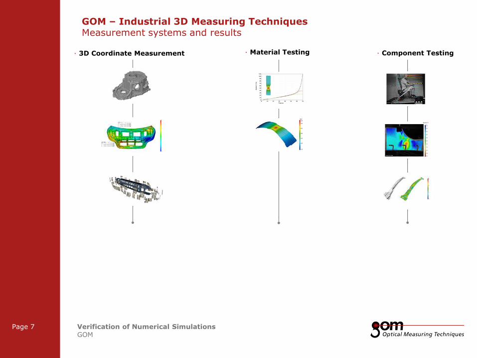
GOM – Industrial 3D Measuring Techniques Measurement systems and results
· Material Testing · 3D Coordinate Measurement · Component Testing
2-Frame Setup / Frame 2 2-Frame Setup / Frame 1
3-Frame Setup / Frame 1 3-Frame Setup / Frame 2 3-Frame Setup / Frame 3
Frame 1
Frame 1
Underline 1
Underline 2
Underline 1
Underline 2
Page 8 Verification of Numerical Simulations GOM
Frame 2
Frame 2 Frame 1
Column 1 Column 2
Column 3 Column 1 Column 2
Content
Content
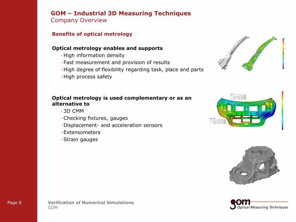
GOM – Industrial 3D Measuring Techniques Company Overview
Benefits of optical metrology
Optical metrology enables and supports
· High information density
· Fast measurement and provision of results
· High degree of flexibility regarding task, place and parts
· High process safety
Optical metrology is used complementary or as an alternative to
· 3D CMM
· Checking fixtures, gauges
· Displacement- and acceleration sensors
· Extensometers
· Strain gauges
Frame 1
Frame 1
Underline 1
Underline 2
Underline 1
Underline 2
Frame 2
Frame 2 Frame 1
Column 1 Column 2
Column 3 Column 1 Column 2
Content
Content
Left Line Title
Upper Line Title
Right Line Title
Verification of Numerical Simulations Webinar Overview

2-Frame Setup / Frame 2 2-Frame Setup / Frame 1
3-Frame Setup / Frame 1 3-Frame Setup / Frame 2 3-Frame Setup / Frame 3
Frame 1
Frame 1
Underline 1
Underline 2
Underline 1
Underline 2
Page 10 Verification of Numerical Simulations GOM
Frame 2
Frame 2 Frame 1
Column 1 Column 2
Column 3 Column 1 Column 2
Content
Content
· Following topics will be discussed during the Application Webinar “Verification of Numerical Simulations”
· Introduction in GOM’s optical measuring systems
· Determination of input parameters for numerical simulations
· Verification procedures for numerical simulations
· Including example applications in
· Sheet metal forming
· Composite component testing
· Biomedical applications
· Fluid dynamics in the Automotive and Aerospace industry
· Supported numerical simulation software packages and formats
Verification of Numerical Simulations Overview
Frame 1
Frame 1
Underline 1
Underline 2
Underline 1
Underline 2
Frame 2
Frame 2 Frame 1
Column 1 Column 2
Column 3 Column 1 Column 2
Content
Content
Left Line Title
Upper Line Title
Right Line Title
Verification of Numerical Simulations Optical Measuring Techniques

2-Frame Setup / Frame 2 2-Frame Setup / Frame 1
3-Frame Setup / Frame 1 3-Frame Setup / Frame 2 3-Frame Setup / Frame 3
Frame 1
Frame 1
Underline 1
Underline 2
Underline 1
Underline 2
Page 12 Verification of Numerical Simulations GOM
Frame 2
Frame 2 Frame 1
Column 1 Column 2
Column 3 Column 1 Column 2
Content
Content
Verification of Numerical Simulations Example Applications

2-Frame Setup / Frame 2 2-Frame Setup / Frame 1
3-Frame Setup / Frame 1 3-Frame Setup / Frame 2 3-Frame Setup / Frame 3
Frame 1
Frame 1
Underline 1
Underline 2
Underline 1
Underline 2
Page 13 Verification of Numerical Simulations GOM
Frame 2
Frame 2 Frame 1
Column 1 Column 2
Column 3 Column 1 Column 2
Content
Content
Verification of Numerical Simulations Overview Finite Element Simulation
Input Geometry (Mesh)
Material Parameters
FE Verification
Boundary Conditions
Shape
Displacement
Strain
Position
FE Optimization
Meshing
2-Frame Setup / Frame 2 2-Frame Setup / Frame 1
3-Frame Setup / Frame 1 3-Frame Setup / Frame 2 3-Frame Setup / Frame 3
Frame 1
Frame 1
Underline 1
Underline 2
Underline 1
Underline 2
Page 14 Verification of Numerical Simulations GOM
Frame 2
Frame 2 Frame 1
Column 1 Column 2
Column 3 Column 1 Column 2
Content
Content
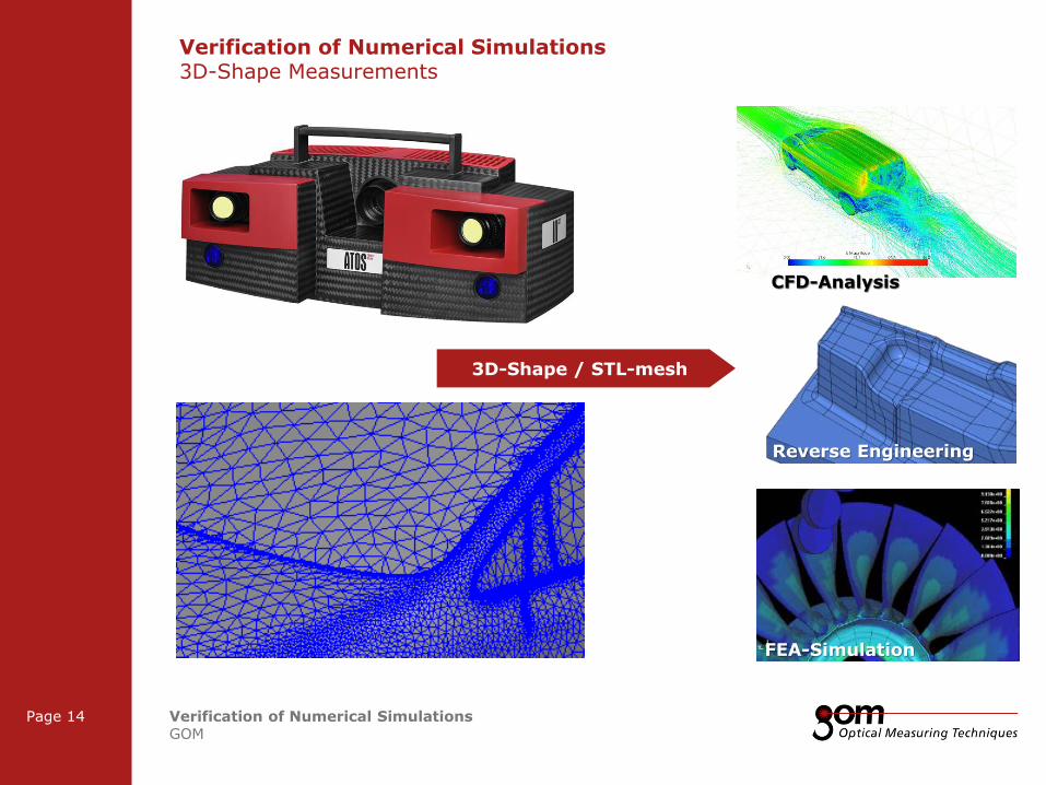
Verification of Numerical Simulations 3D-Shape Measurements
Reverse Engineering
FEA-Simulation
CFD-Analysis
3D-Shape / STL-mesh
2-Frame Setup / Frame 2 2-Frame Setup / Frame 1
3-Frame Setup / Frame 1 3-Frame Setup / Frame 2 3-Frame Setup / Frame 3
Frame 1
Frame 1
Underline 1
Underline 2
Underline 1
Underline 2
Page 15 Verification of Numerical Simulations GOM
Frame 2
Frame 2 Frame 1
Column 1 Column 2
Column 3 Column 1 Column 2
Content
Content
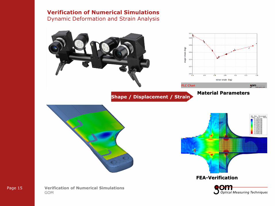
Verification of Numerical Simulations Dynamic Deformation and Strain Analysis
FEA-Verification
Material Parameters
Shape / Displacement / Strain
2-Frame Setup / Frame 2 2-Frame Setup / Frame 1
3-Frame Setup / Frame 1 3-Frame Setup / Frame 2 3-Frame Setup / Frame 3
Frame 1
Frame 1
Underline 1
Underline 2
Underline 1
Underline 2
Page 16 Verification of Numerical Simulations GOM
Frame 2
Frame 2 Frame 1
Column 1 Column 2
Column 3 Column 1 Column 2
Content
Content
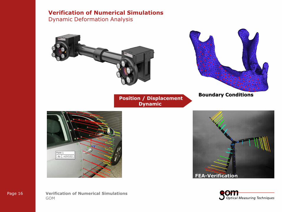
Boundary Conditions
Verification of Numerical Simulations Dynamic Deformation Analysis
Position / Displacement Dynamic
FEA-Verification
2-Frame Setup / Frame 2 2-Frame Setup / Frame 1
3-Frame Setup / Frame 1 3-Frame Setup / Frame 2 3-Frame Setup / Frame 3
Frame 1
Frame 1
Underline 1
Underline 2
Underline 1
Underline 2
Page 17 Verification of Numerical Simulations GOM
Frame 2
Frame 2 Frame 1
Column 1 Column 2
Column 3 Column 1 Column 2
Content
Content
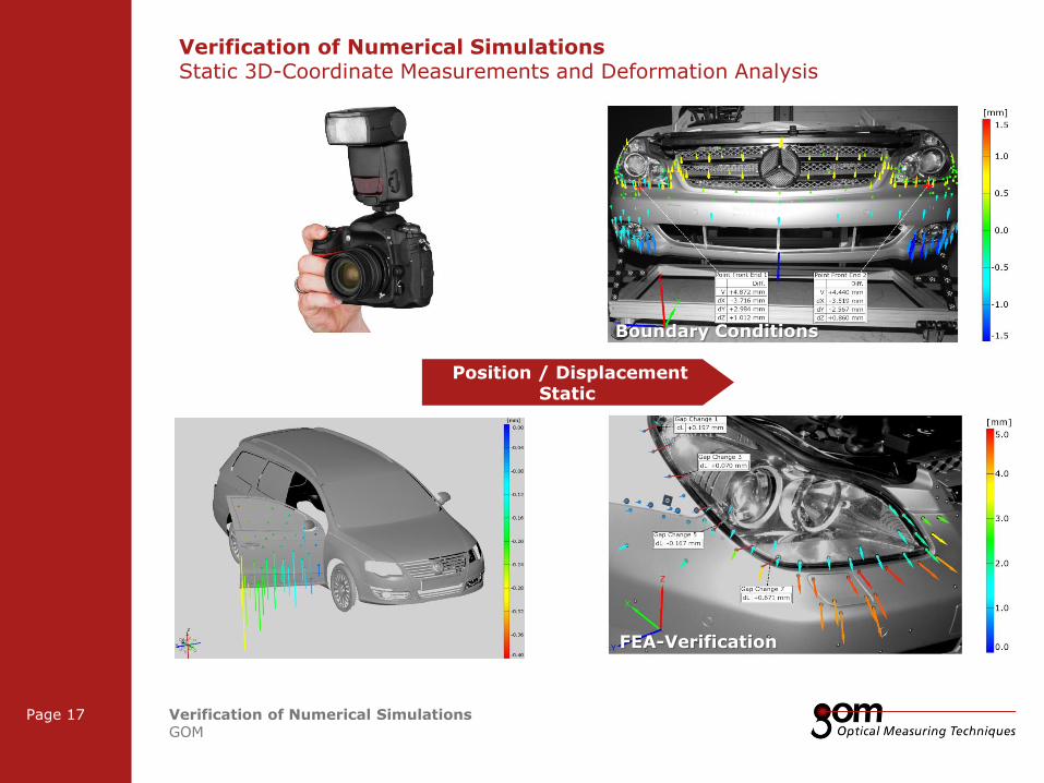
Boundary Conditions
Verification of Numerical Simulations Static 3D-Coordinate Measurements and Deformation Analysis
Position / Displacement Static
FEA-Verification
2-Frame Setup / Frame 2 2-Frame Setup / Frame 1
3-Frame Setup / Frame 1 3-Frame Setup / Frame 2 3-Frame Setup / Frame 3
Frame 1
Frame 1
Underline 1
Underline 2
Underline 1
Underline 2
Page 18 Verification of Numerical Simulations GOM
Frame 2
Frame 2 Frame 1
Column 1 Column 2
Column 3 Column 1 Column 2
Content
Content
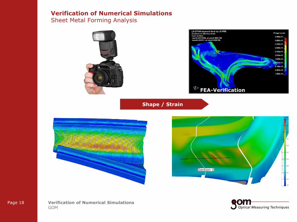
Verification of Numerical Simulations Sheet Metal Forming Analysis
FEA-Verification
Shape / Strain
2-Frame Setup / Frame 2 2-Frame Setup / Frame 1
3-Frame Setup / Frame 1 3-Frame Setup / Frame 2 3-Frame Setup / Frame 3
Frame 1
Frame 1
Underline 1
Underline 2
Underline 1
Underline 2
Page 19 Verification of Numerical Simulations GOM
Frame 2
Frame 2 Frame 1
Column 1 Column 2
Column 3 Column 1 Column 2
Content
Content
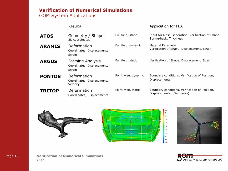
Verification of Numerical Simulations GOM System Applications
Results Application for FEA
ATOS Geometry / Shape 3D coordinates
Full field, static Input for Mesh Generation, Verification of Shape Spring-back, Thickness
ARAMIS Deformation Coordinates, Displacements,
Strain
Full field, dynamic Material Parameter Verification of Shape, Displacement, Strain
ARGUS Forming Analysis Coordinates, Displacements,
Strain
Full field, static
Verification of Shape, Displacement, Strain
PONTOS Deformation Coordinates, Displacements, Velocity
Point wise, dynamic Boundary conditions, Verification of Position,
Displacements
TRITOP Deformation Coordinates, Displacements
Point wise, static
Boundary conditions, Verification of Position, Displacements, (Geometry)
Frame 1
Frame 1
Underline 1
Underline 2
Underline 1
Underline 2
Frame 2
Frame 2 Frame 1
Column 1 Column 2
Column 3 Column 1 Column 2
Content
Content
Left Line Title
Upper Line Title
Right Line Title
Verification of Numerical Simulations Determination of Input Parameters
2-Frame Setup / Frame 2 2-Frame Setup / Frame 1
3-Frame Setup / Frame 1 3-Frame Setup / Frame 2 3-Frame Setup / Frame 3
Frame 1
Frame 1
Underline 1
Underline 2
Underline 1
Underline 2
Page 21 Verification of Numerical Simulations GOM
Frame 2
Frame 2 Frame 1
Column 1 Column 2
Column 3 Column 1 Column 2
Content
Content
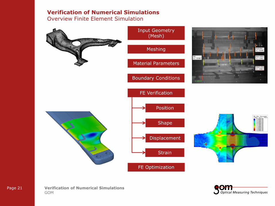
Verification of Numerical Simulations Overview Finite Element Simulation
Input Geometry (Mesh)
Material Parameters
FE Verification
Boundary Conditions
Shape
Displacement
Strain
Position
FE Optimization
Meshing
2-Frame Setup / Frame 2 2-Frame Setup / Frame 1
3-Frame Setup / Frame 1 3-Frame Setup / Frame 2 3-Frame Setup / Frame 3
Frame 1
Frame 1
Underline 1
Underline 2
Underline 1
Underline 2
Page 22 Verification of Numerical Simulations GOM
Frame 2
Frame 2 Frame 1
Column 1 Column 2
Column 3 Column 1 Column 2
Content
Content
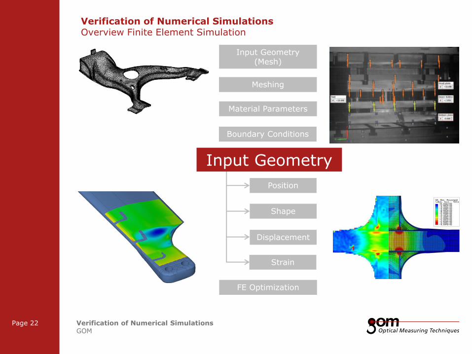
Verification of Numerical Simulations Overview Finite Element Simulation
Input Geometry (Mesh)
Material Parameters
FE Verification
Boundary Conditions
Shape
Displacement
Strain
Position
FE Optimization
Meshing
Input Geometry
2-Frame Setup / Frame 2 2-Frame Setup / Frame 1
3-Frame Setup / Frame 1 3-Frame Setup / Frame 2 3-Frame Setup / Frame 3
Frame 1
Frame 1
Underline 1
Underline 2
Underline 1
Underline 2
Page 23 Verification of Numerical Simulations GOM
Frame 2
Frame 2 Frame 1
Column 1 Column 2
Column 3 Column 1 Column 2
Content
Content
Verification of Numerical Simulations Determination of Input Parameters
· Input geometry for numerical simulation
· Numerical simulations are initially depending on 3D input geometries which are usually taken from construction models (CAD)
· Due to differences in the 3D shape of CAD data sets and prototypes the reliability of numerical simulations are sometimes questionable
· Thus the accuracy and reliability of numerical simulations can be improved using the real parts geometry
2-Frame Setup / Frame 2 2-Frame Setup / Frame 1
3-Frame Setup / Frame 1 3-Frame Setup / Frame 2 3-Frame Setup / Frame 3
Frame 1
Frame 1
Underline 1
Underline 2
Underline 1
Underline 2
Page 24 Verification of Numerical Simulations GOM
Frame 2
Frame 2 Frame 1
Column 1 Column 2
Column 3 Column 1 Column 2
Content
Content
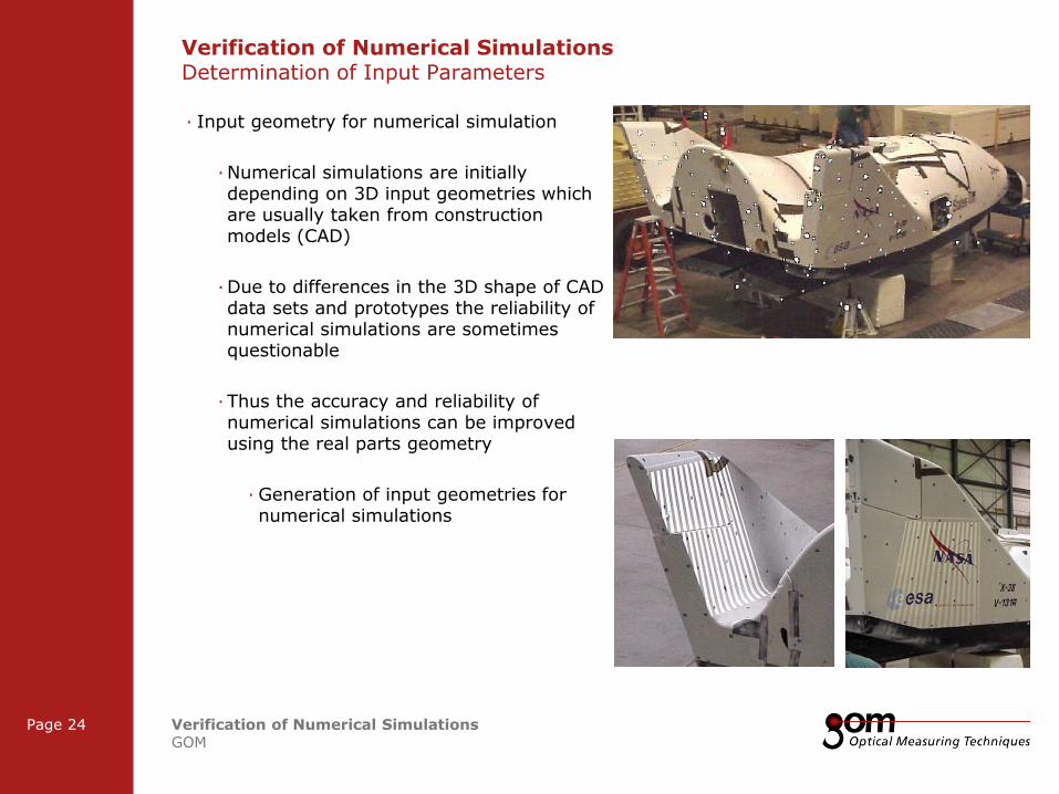
Verification of Numerical Simulations Determination of Input Parameters
· Input geometry for numerical simulation
· Numerical simulations are initially depending on 3D input geometries which are usually taken from construction models (CAD)
· Due to differences in the 3D shape of CAD data sets and prototypes the reliability of numerical simulations are sometimes questionable
· Thus the accuracy and reliability of numerical simulations can be improved using the real parts geometry
· Generation of input geometries for numerical simulations

2-Frame Setup / Frame 2 2-Frame Setup / Frame 1
3-Frame Setup / Frame 1 3-Frame Setup / Frame 2 3-Frame Setup / Frame 3
Frame 1
Frame 1
Underline 1
Underline 2
Underline 1
Underline 2
Page 25 Verification of Numerical Simulations GOM
Frame 2
Frame 2 Frame 1
Column 1 Column 2
Column 3 Column 1 Column 2
Content
Content
Verification of Numerical Simulations Determination of Input Parameters
· Input geometry for numerical simulation
· Numerical simulations are initially depending on 3D input geometries which are usually taken from construction models (CAD)
· Due to differences in the 3D shape of CAD data sets and prototypes the reliability of numerical simulations are sometimes questionable
· Thus the accuracy and reliability of numerical simulations can be improved using the real parts geometry
· Generation of input geometries for numerical simulations
Section based reverse engineered CAD model from scan data
2-Frame Setup / Frame 2 2-Frame Setup / Frame 1
3-Frame Setup / Frame 1 3-Frame Setup / Frame 2 3-Frame Setup / Frame 3
Frame 1
Frame 1
Underline 1
Underline 2
Underline 1
Underline 2
Page 26 Verification of Numerical Simulations GOM
Frame 2
Frame 2 Frame 1
Column 1 Column 2
Column 3 Column 1 Column 2
Content
Content
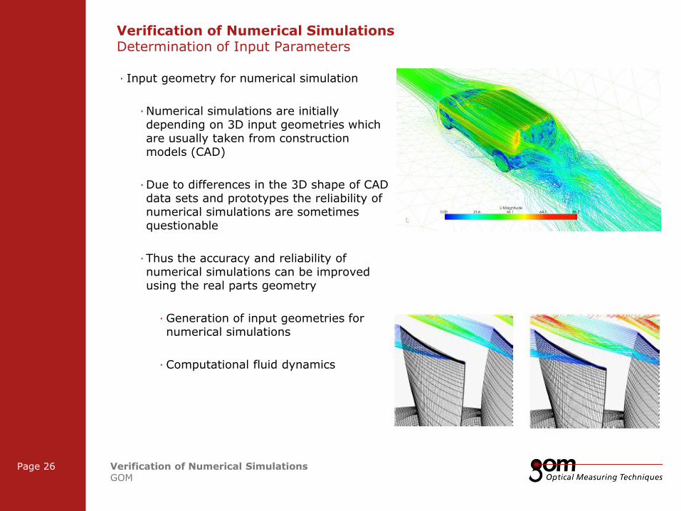
Verification of Numerical Simulations Determination of Input Parameters
· Input geometry for numerical simulation
· Numerical simulations are initially depending on 3D input geometries which are usually taken from construction models (CAD)
· Due to differences in the 3D shape of CAD data sets and prototypes the reliability of numerical simulations are sometimes questionable
· Thus the accuracy and reliability of numerical simulations can be improved using the real parts geometry
· Generation of input geometries for numerical simulations
· Computational fluid dynamics

2-Frame Setup / Frame 2 2-Frame Setup / Frame 1
3-Frame Setup / Frame 1 3-Frame Setup / Frame 2 3-Frame Setup / Frame 3
Frame 1
Frame 1
Underline 1
Underline 2
Underline 1
Underline 2
Page 27 Verification of Numerical Simulations GOM
Frame 2
Frame 2 Frame 1
Column 1 Column 2
Column 3 Column 1 Column 2
Content
Content
Verification of Numerical Simulations Overview Finite Element Simulation
Input Geometry (Mesh)
Material Parameters
FE Verification
Boundary Conditions
Shape
Displacement
Strain
Position
FE Optimization
Meshing
2-Frame Setup / Frame 2 2-Frame Setup / Frame 1
3-Frame Setup / Frame 1 3-Frame Setup / Frame 2 3-Frame Setup / Frame 3
Frame 1
Frame 1
Underline 1
Underline 2
Underline 1
Underline 2
Page 28 Verification of Numerical Simulations GOM
Frame 2
Frame 2 Frame 1
Column 1 Column 2
Column 3 Column 1 Column 2
Content
Content
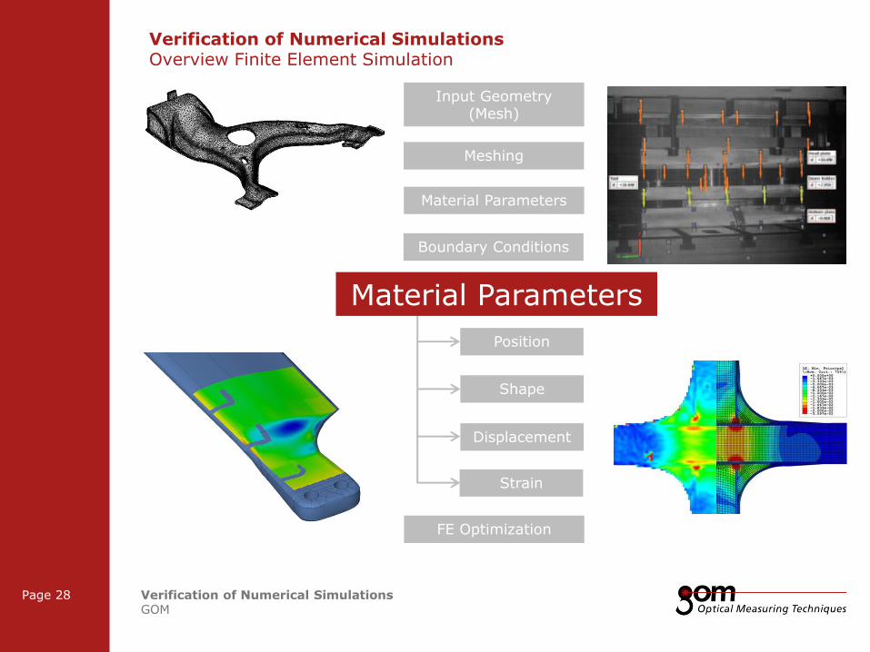
Verification of Numerical Simulations Overview Finite Element Simulation
Input Geometry (Mesh)
Material Parameters
FE Verification
Boundary Conditions
Shape
Displacement
Strain
Position
FE Optimization
Meshing
Material Parameters
2-Frame Setup / Frame 2 2-Frame Setup / Frame 1
3-Frame Setup / Frame 1 3-Frame Setup / Frame 2 3-Frame Setup / Frame 3
Frame 1
Frame 1
Underline 1
Underline 2
Underline 1
Underline 2
Page 29 Verification of Numerical Simulations GOM
Frame 2
Frame 2 Frame 1
Column 1 Column 2
Column 3 Column 1 Column 2
Content
Content
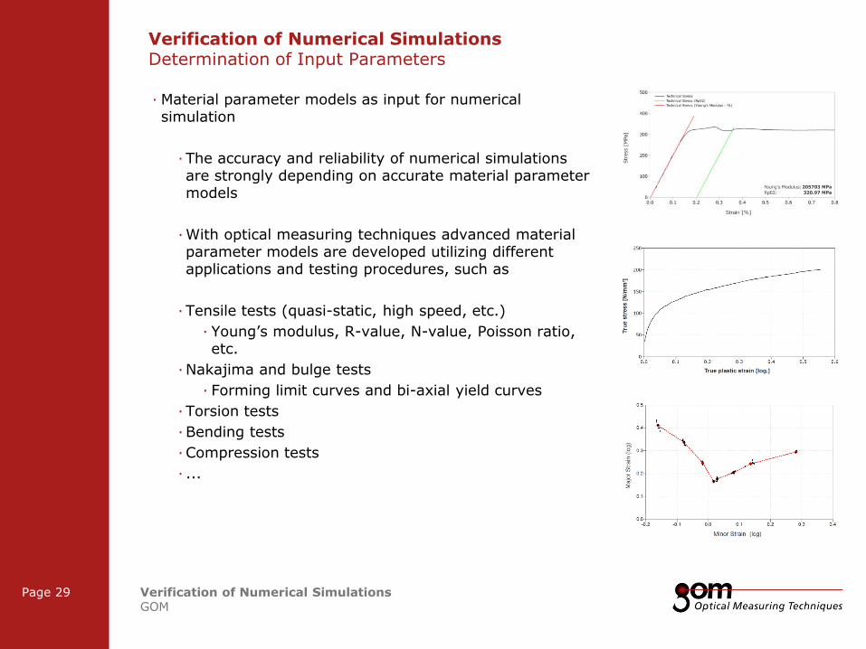
Verification of Numerical Simulations Determination of Input Parameters
· Material parameter models as input for numerical simulation
· The accuracy and reliability of numerical simulations are strongly depending on accurate material parameter models
· With optical measuring techniques advanced material parameter models are developed utilizing different applications and testing procedures, such as
· Tensile tests (quasi-static, high speed, etc.)
· Young’s modulus, R-value, N-value, Poisson ratio, etc.
· Nakajima and bulge tests
· Forming limit curves and bi-axial yield curves
· Torsion tests
· Bending tests
· Compression tests
· ...

2-Frame Setup / Frame 2 2-Frame Setup / Frame 1
3-Frame Setup / Frame 1 3-Frame Setup / Frame 2 3-Frame Setup / Frame 3
Frame 1
Frame 1
Underline 1
Underline 2
Underline 1
Underline 2
Page 30 Verification of Numerical Simulations GOM
Frame 2
Frame 2 Frame 1
Column 1 Column 2
Column 3 Column 1 Column 2
Content
Content
Verification of Numerical Simulations Overview Finite Element Simulation
Input Geometry (Mesh)
Material Parameters
FE Verification
Boundary Conditions
Shape
Displacement
Strain
Position
FE Optimization
Meshing

2-Frame Setup / Frame 2 2-Frame Setup / Frame 1
3-Frame Setup / Frame 1 3-Frame Setup / Frame 2 3-Frame Setup / Frame 3
Frame 1
Frame 1
Underline 1
Underline 2
Underline 1
Underline 2
Page 31 Verification of Numerical Simulations GOM
Frame 2
Frame 2 Frame 1
Column 1 Column 2
Column 3 Column 1 Column 2
Content
Content
Verification of Numerical Simulations Overview Finite Element Simulation
Input Geometry (Mesh)
Material Parameters
FE Verification
Boundary Conditions
Shape
Displacement
Strain
Position
FE Optimization
Meshing
Boundary Conditions
2-Frame Setup / Frame 2 2-Frame Setup / Frame 1
3-Frame Setup / Frame 1 3-Frame Setup / Frame 2 3-Frame Setup / Frame 3
Frame 1
Frame 1
Underline 1
Underline 2
Underline 1
Underline 2
Page 32 Verification of Numerical Simulations GOM
Frame 2
Frame 2 Frame 1
Column 1 Column 2
Column 3 Column 1 Column 2
Content
Content
Verification of Numerical Simulations Determination of Input Parameters
· Boundary conditions as input for numerical simulations
· Numerical simulations strongly depend on the input of boundary conditions which represent manufacturing and testing conditions

2-Frame Setup / Frame 2 2-Frame Setup / Frame 1
3-Frame Setup / Frame 1 3-Frame Setup / Frame 2 3-Frame Setup / Frame 3
Frame 1
Frame 1
Underline 1
Underline 2
Underline 1
Underline 2
Page 33 Verification of Numerical Simulations GOM
Frame 2
Frame 2 Frame 1
Column 1 Column 2
Column 3 Column 1 Column 2
Content
Content
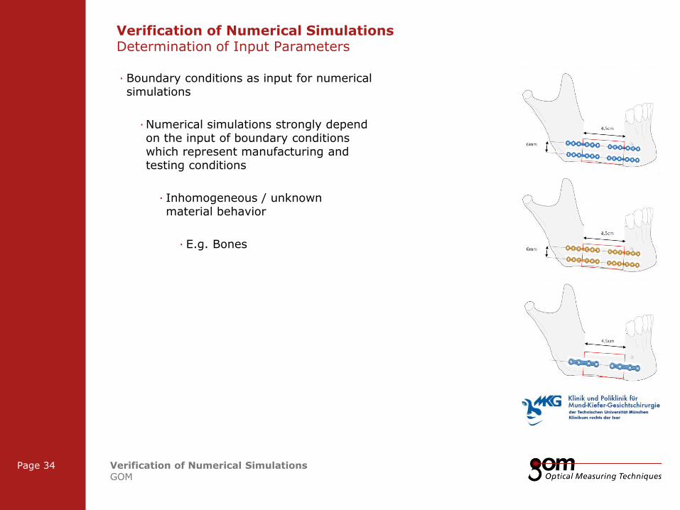
Verification of Numerical Simulations Determination of Input Parameters
· Boundary conditions as input for numerical simulations
· Numerical simulations strongly depend on the input of boundary conditions which represent manufacturing and testing conditions
· Inhomogeneous / unknown material behavior
· E.g. Bones
2-Frame Setup / Frame 2 2-Frame Setup / Frame 1
3-Frame Setup / Frame 1 3-Frame Setup / Frame 2 3-Frame Setup / Frame 3
Frame 1
Frame 1
Underline 1
Underline 2
Underline 1
Underline 2
Page 34 Verification of Numerical Simulations GOM
Frame 2
Frame 2 Frame 1
Column 1 Column 2
Column 3 Column 1 Column 2
Content
Content
Verification of Numerical Simulations Determination of Input Parameters
· Boundary conditions as input for numerical simulations
· Numerical simulations strongly depend on the input of boundary conditions which represent manufacturing and testing conditions
· Inhomogeneous / unknown material behavior
· E.g. Bones

2-Frame Setup / Frame 2 2-Frame Setup / Frame 1
3-Frame Setup / Frame 1 3-Frame Setup / Frame 2 3-Frame Setup / Frame 3
Frame 1
Frame 1
Underline 1
Underline 2
Underline 1
Underline 2
Page 35 Verification of Numerical Simulations GOM
Frame 2
Frame 2 Frame 1
Column 1 Column 2
Column 3 Column 1 Column 2
Content
Content
Verification of Numerical Simulations Determination of Input Parameters
· Boundary conditions as input for numerical simulations
· Numerical simulations strongly depend on the input of boundary conditions which represent manufacturing and testing conditions
· Inhomogeneous / unknown material behavior
· E.g. Bones
PONTOS Measurement
FEA Input Geometry
2-Frame Setup / Frame 2 2-Frame Setup / Frame 1
3-Frame Setup / Frame 1 3-Frame Setup / Frame 2 3-Frame Setup / Frame 3
Frame 1
Frame 1
Underline 1
Underline 2
Underline 1
Underline 2
Page 36 Verification of Numerical Simulations GOM
Frame 2
Frame 2 Frame 1
Column 1 Column 2
Column 3 Column 1 Column 2
Content
Content
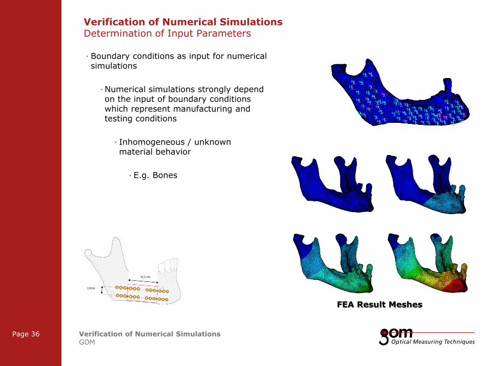
Verification of Numerical Simulations Determination of Input Parameters
· Boundary conditions as input for numerical simulations
· Numerical simulations strongly depend on the input of boundary conditions which represent manufacturing and testing conditions
· Inhomogeneous / unknown material behavior
· E.g. Bones
FEA Result Meshes
2-Frame Setup / Frame 2 2-Frame Setup / Frame 1
3-Frame Setup / Frame 1 3-Frame Setup / Frame 2 3-Frame Setup / Frame 3
Frame 1
Frame 1
Underline 1
Underline 2
Underline 1
Underline 2
Page 37 Verification of Numerical Simulations GOM
Frame 2
Frame 2 Frame 1
Column 1 Column 2
Column 3 Column 1 Column 2
Content
Content
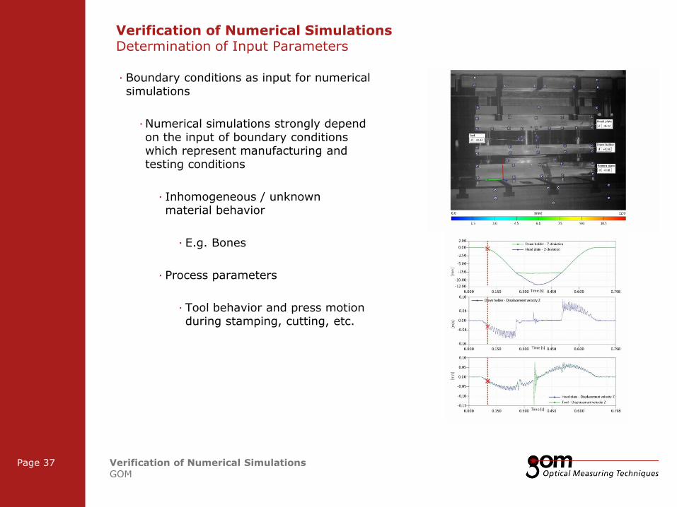
Verification of Numerical Simulations Determination of Input Parameters
· Boundary conditions as input for numerical simulations
· Numerical simulations strongly depend on the input of boundary conditions which represent manufacturing and testing conditions
· Inhomogeneous / unknown material behavior
· E.g. Bones
· Process parameters
· Tool behavior and press motion during stamping, cutting, etc.

Frame 1
Frame 1
Underline 1
Underline 2
Underline 1
Underline 2
Frame 2
Frame 2 Frame 1
Column 1 Column 2
Column 3 Column 1 Column 2
Content
Content
Left Line Title
Upper Line Title
Right Line Title
Verification of Numerical Simulations Common Verification Procedures
2-Frame Setup / Frame 2 2-Frame Setup / Frame 1
3-Frame Setup / Frame 1 3-Frame Setup / Frame 2 3-Frame Setup / Frame 3
Frame 1
Frame 1
Underline 1
Underline 2
Underline 1
Underline 2
Page 39 Verification of Numerical Simulations GOM
Frame 2
Frame 2 Frame 1
Column 1 Column 2
Column 3 Column 1 Column 2
Content
Content
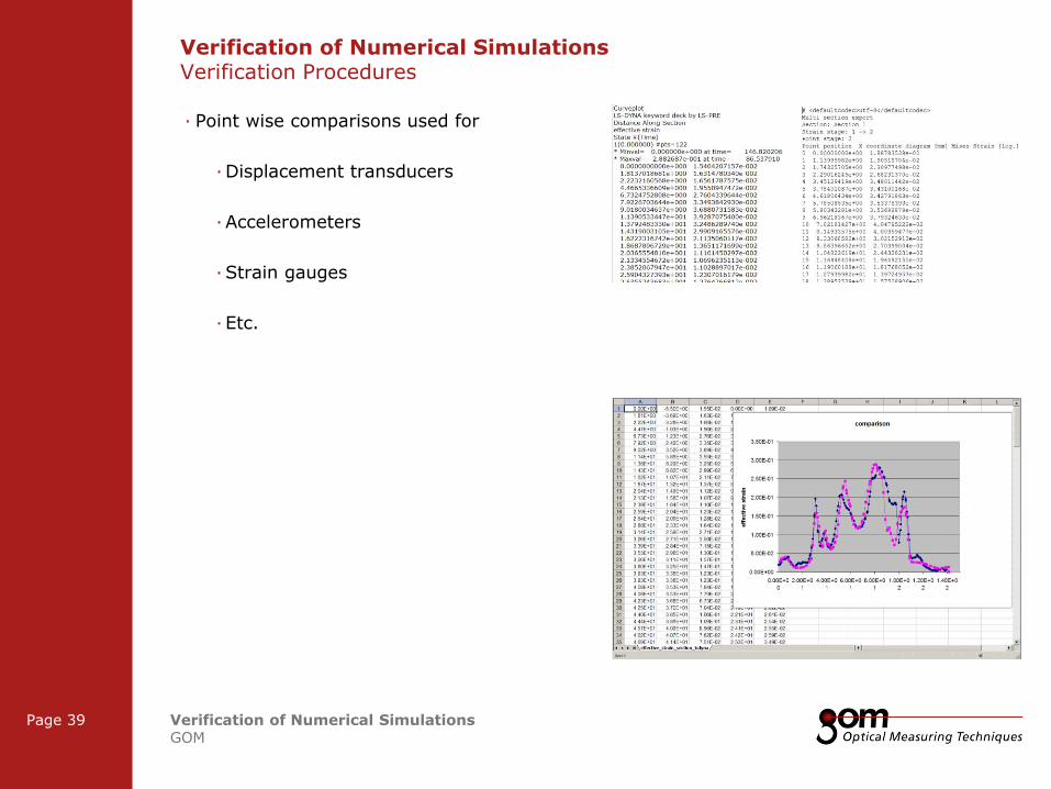
Verification of Numerical Simulations Verification Procedures
· Point wise comparisons used for
· Displacement transducers
· Accelerometers
· Strain gauges
· Etc.
2-Frame Setup / Frame 2 2-Frame Setup / Frame 1
3-Frame Setup / Frame 1 3-Frame Setup / Frame 2 3-Frame Setup / Frame 3
Frame 1
Frame 1
Underline 1
Underline 2
Underline 1
Underline 2
Page 40 Verification of Numerical Simulations GOM
Frame 2
Frame 2 Frame 1
Column 1 Column 2
Column 3 Column 1 Column 2
Content
Content
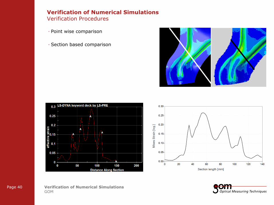
Verification of Numerical Simulations Verification Procedures
· Point wise comparison
· Section based comparison
2-Frame Setup / Frame 2 2-Frame Setup / Frame 1
3-Frame Setup / Frame 1 3-Frame Setup / Frame 2 3-Frame Setup / Frame 3
Frame 1
Frame 1
Underline 1
Underline 2
Underline 1
Underline 2
Page 41 Verification of Numerical Simulations GOM
Frame 2
Frame 2 Frame 1
Column 1 Column 2
Column 3 Column 1 Column 2
Content
Content
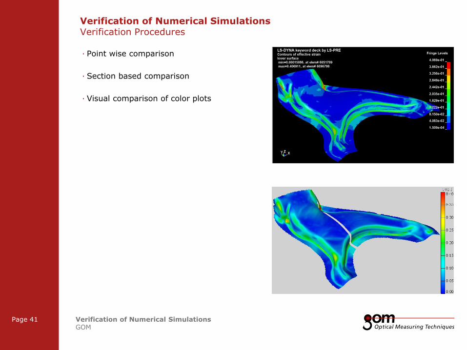
Verification of Numerical Simulations Verification Procedures
· Point wise comparison
· Section based comparison
· Visual comparison of color plots
2-Frame Setup / Frame 2 2-Frame Setup / Frame 1
3-Frame Setup / Frame 1 3-Frame Setup / Frame 2 3-Frame Setup / Frame 3
Frame 1
Frame 1
Underline 1
Underline 2
Underline 1
Underline 2
Page 42 Verification of Numerical Simulations GOM
Frame 2
Frame 2 Frame 1
Column 1 Column 2
Column 3 Column 1 Column 2
Content
Content
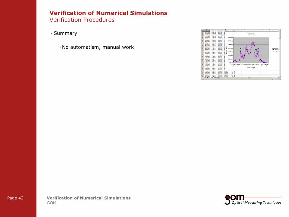
· Summary
· No automatism, manual work
Verification of Numerical Simulations Verification Procedures

2-Frame Setup / Frame 2 2-Frame Setup / Frame 1
3-Frame Setup / Frame 1 3-Frame Setup / Frame 2 3-Frame Setup / Frame 3
Frame 1
Frame 1
Underline 1
Underline 2
Underline 1
Underline 2
Page 43 Verification of Numerical Simulations GOM
Frame 2
Frame 2 Frame 1
Column 1 Column 2
Column 3 Column 1 Column 2
Content
Content
· Summary
· No automatism, manual work
· Due to user interaction very fault-prone
· Definition of points, sections, etc. in correct corresponding positions in FEA and measurement results
Verification of Numerical Simulations Verification Procedures
2-Frame Setup / Frame 2 2-Frame Setup / Frame 1
3-Frame Setup / Frame 1 3-Frame Setup / Frame 2 3-Frame Setup / Frame 3
Frame 1
Frame 1
Underline 1
Underline 2
Underline 1
Underline 2
Page 44 Verification of Numerical Simulations GOM
Frame 2
Frame 2 Frame 1
Column 1 Column 2
Column 3 Column 1 Column 2
Content
Content
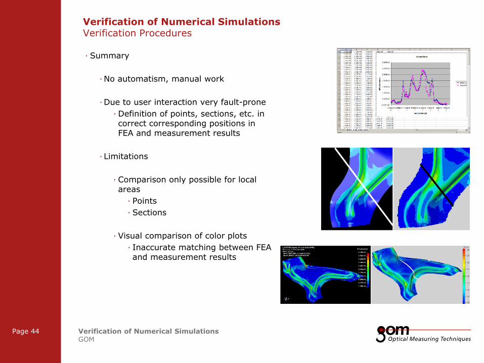
· Summary
· No automatism, manual work
· Due to user interaction very fault-prone
· Definition of points, sections, etc. in correct corresponding positions in FEA and measurement results
· Limitations
· Comparison only possible for local areas
· Points
· Sections
· Visual comparison of color plots
· Inaccurate matching between FEA and measurement results
Verification of Numerical Simulations Verification Procedures

Frame 1
Frame 1
Underline 1
Underline 2
Underline 1
Underline 2
Frame 2
Frame 2 Frame 1
Column 1 Column 2
Column 3 Column 1 Column 2
Content
Content
Left Line Title
Upper Line Title
Right Line Title
Verification of Numerical Simulations Verification Procedure using 3D Data

2-Frame Setup / Frame 2 2-Frame Setup / Frame 1
3-Frame Setup / Frame 1 3-Frame Setup / Frame 2 3-Frame Setup / Frame 3
Frame 1
Frame 1
Underline 1
Underline 2
Underline 1
Underline 2
Page 46 Verification of Numerical Simulations GOM
Frame 2
Frame 2 Frame 1
Column 1 Column 2
Column 3 Column 1 Column 2
Content
Content
Verification of Numerical Simulations Overview Finite Element Simulation
Input Geometry (Mesh)
Material Parameters
FE Verification
Boundary Conditions
Shape
Displacement
Strain
Position
FE Optimization
Meshing

2-Frame Setup / Frame 2 2-Frame Setup / Frame 1
3-Frame Setup / Frame 1 3-Frame Setup / Frame 2 3-Frame Setup / Frame 3
Frame 1
Frame 1
Underline 1
Underline 2
Underline 1
Underline 2
Page 47 Verification of Numerical Simulations GOM
Frame 2
Frame 2 Frame 1
Column 1 Column 2
Column 3 Column 1 Column 2
Content
Content
Verification of Numerical Simulations Overview Finite Element Simulation
Input Geometry (Mesh)
Material Parameters
FE Verification
Boundary Conditions
Shape
Displacement
Strain
Position
FE Optimization
Meshing
FE Verification
2-Frame Setup / Frame 2 2-Frame Setup / Frame 1
3-Frame Setup / Frame 1 3-Frame Setup / Frame 2 3-Frame Setup / Frame 3
Frame 1
Frame 1
Underline 1
Underline 2
Underline 1
Underline 2
Page 48 Verification of Numerical Simulations GOM
Frame 2
Frame 2 Frame 1
Column 1 Column 2
Column 3 Column 1 Column 2
Content
Content
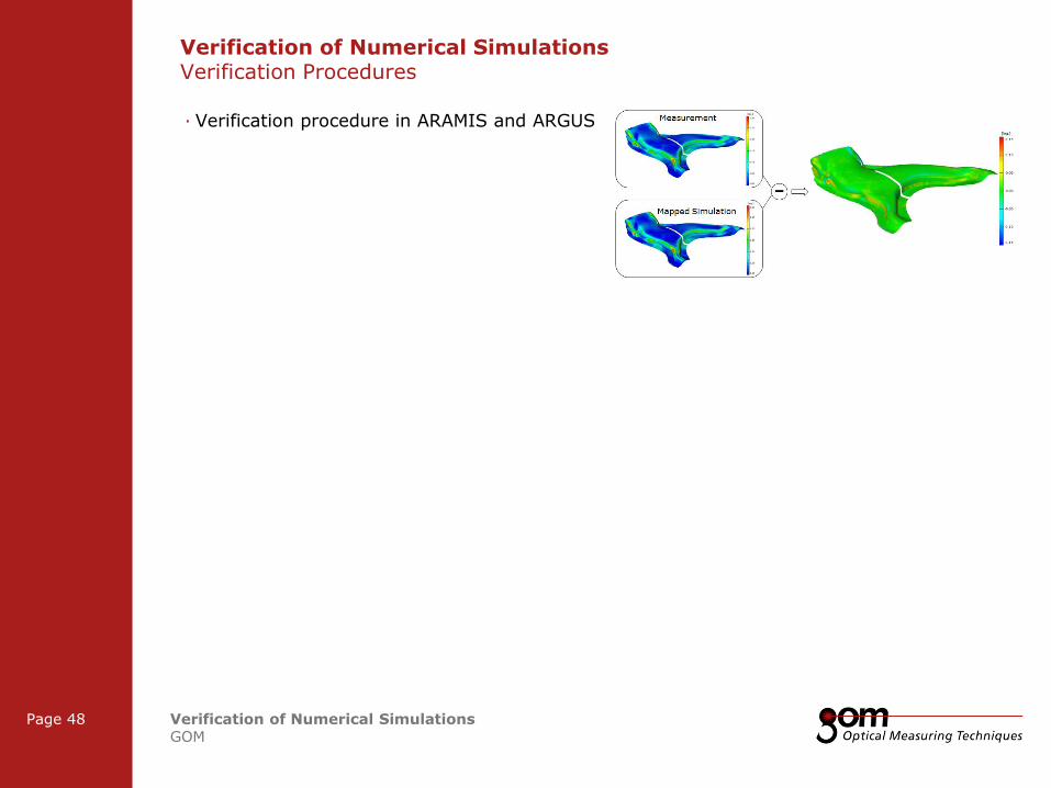
· Verification procedure in ARAMIS and ARGUS
Verification of Numerical Simulations Verification Procedures
2-Frame Setup / Frame 2 2-Frame Setup / Frame 1
3-Frame Setup / Frame 1 3-Frame Setup / Frame 2 3-Frame Setup / Frame 3
Frame 1
Frame 1
Underline 1
Underline 2
Underline 1
Underline 2
Page 49 Verification of Numerical Simulations GOM
Frame 2
Frame 2 Frame 1
Column 1 Column 2
Column 3 Column 1 Column 2
Content
Content
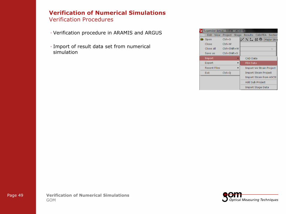
· Verification procedure in ARAMIS and ARGUS
· Import of result data set from numerical simulation
Verification of Numerical Simulations Verification Procedures
2-Frame Setup / Frame 2 2-Frame Setup / Frame 1
3-Frame Setup / Frame 1 3-Frame Setup / Frame 2 3-Frame Setup / Frame 3
Frame 1
Frame 1
Underline 1
Underline 2
Underline 1
Underline 2
Page 50 Verification of Numerical Simulations GOM
Frame 2
Frame 2 Frame 1
Column 1 Column 2
Column 3 Column 1 Column 2
Content
Content
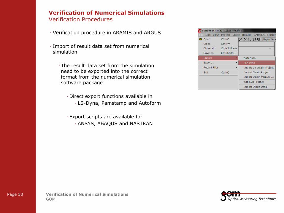
· Verification procedure in ARAMIS and ARGUS
· Import of result data set from numerical simulation
· The result data set from the simulation need to be exported into the correct format from the numerical simulation software package
· Direct export functions available in
· LS-Dyna, Pamstamp and Autoform
· Export scripts are available for
· ANSYS, ABAQUS and NASTRAN
Verification of Numerical Simulations Verification Procedures
2-Frame Setup / Frame 2 2-Frame Setup / Frame 1
3-Frame Setup / Frame 1 3-Frame Setup / Frame 2 3-Frame Setup / Frame 3
Frame 1
Frame 1
Underline 1
Underline 2
Underline 1
Underline 2
Page 51 Verification of Numerical Simulations GOM
Frame 2
Frame 2 Frame 1
Column 1 Column 2
Column 3 Column 1 Column 2
Content
Content
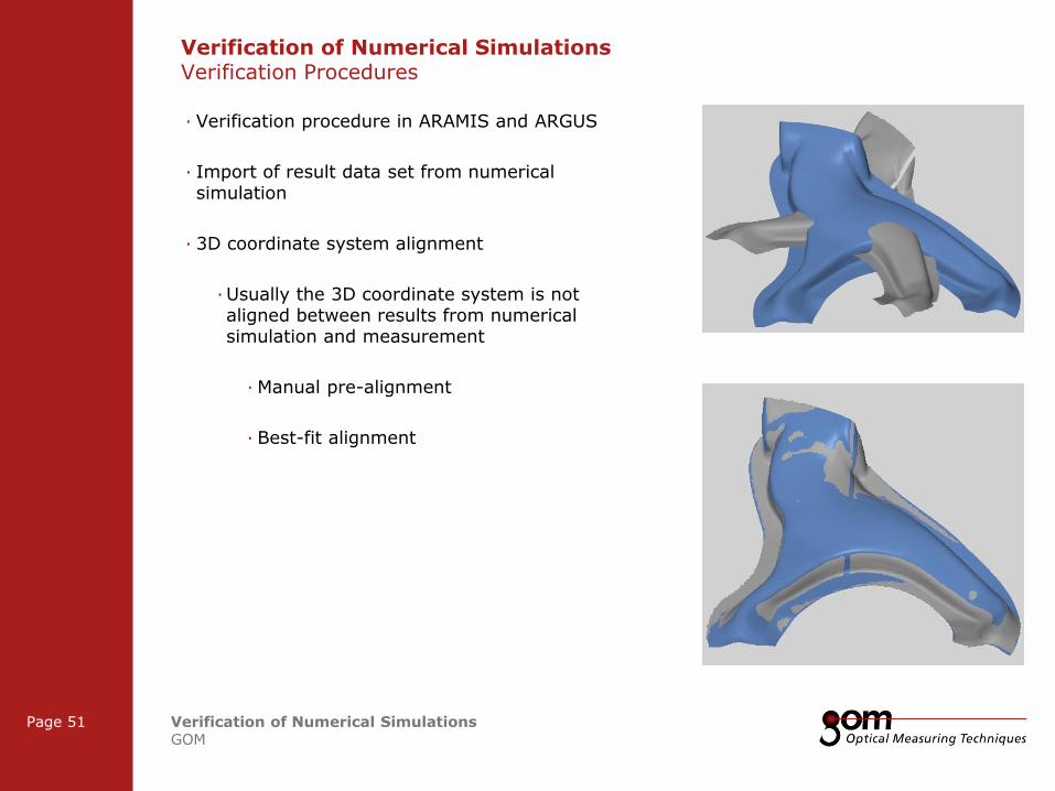
· Verification procedure in ARAMIS and ARGUS
· Import of result data set from numerical simulation
· 3D coordinate system alignment
· Usually the 3D coordinate system is not aligned between results from numerical simulation and measurement
· Manual pre-alignment
· Best-fit alignment
Verification of Numerical Simulations Verification Procedures
2-Frame Setup / Frame 2 2-Frame Setup / Frame 1
3-Frame Setup / Frame 1 3-Frame Setup / Frame 2 3-Frame Setup / Frame 3
Frame 1
Frame 1
Underline 1
Underline 2
Underline 1
Underline 2
Page 52 Verification of Numerical Simulations GOM
Frame 2
Frame 2 Frame 1
Column 1 Column 2
Column 3 Column 1 Column 2
Content
Content
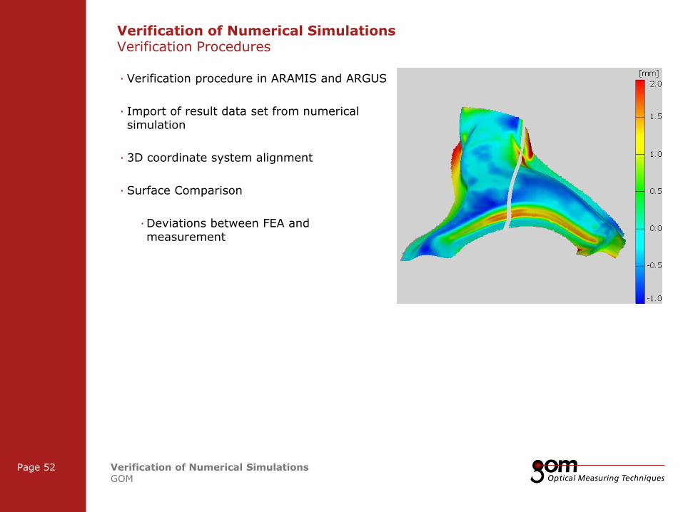
· Verification procedure in ARAMIS and ARGUS
· Import of result data set from numerical simulation
· 3D coordinate system alignment
· Surface Comparison
· Deviations between FEA and measurement
Verification of Numerical Simulations Verification Procedures

2-Frame Setup / Frame 2 2-Frame Setup / Frame 1
3-Frame Setup / Frame 1 3-Frame Setup / Frame 2 3-Frame Setup / Frame 3
Frame 1
Frame 1
Underline 1
Underline 2
Underline 1
Underline 2
Page 53 Verification of Numerical Simulations GOM
Frame 2
Frame 2 Frame 1
Column 1 Column 2
Column 3 Column 1 Column 2
Content
Content
· Verification procedure in ARAMIS and ARGUS
· Import of result data set from numerical simulation
· 3D coordinate system alignment
· Surface Comparison
· Deviations between FEA and measurement
· With “small enough” deviation between the two surfaces the comparison of further result data, such as displacement and strain, is useful
Verification of Numerical Simulations Verification Procedures
2-Frame Setup / Frame 2 2-Frame Setup / Frame 1
3-Frame Setup / Frame 1 3-Frame Setup / Frame 2 3-Frame Setup / Frame 3
Frame 1
Frame 1
Underline 1
Underline 2
Underline 1
Underline 2
Page 54 Verification of Numerical Simulations GOM
Frame 2
Frame 2 Frame 1
Column 1 Column 2
Column 3 Column 1 Column 2
Content
Content
· Verification procedure in ARAMIS and ARGUS
· Import of result data set from numerical simulation
· 3D coordinate system alignment
· Surface Comparison
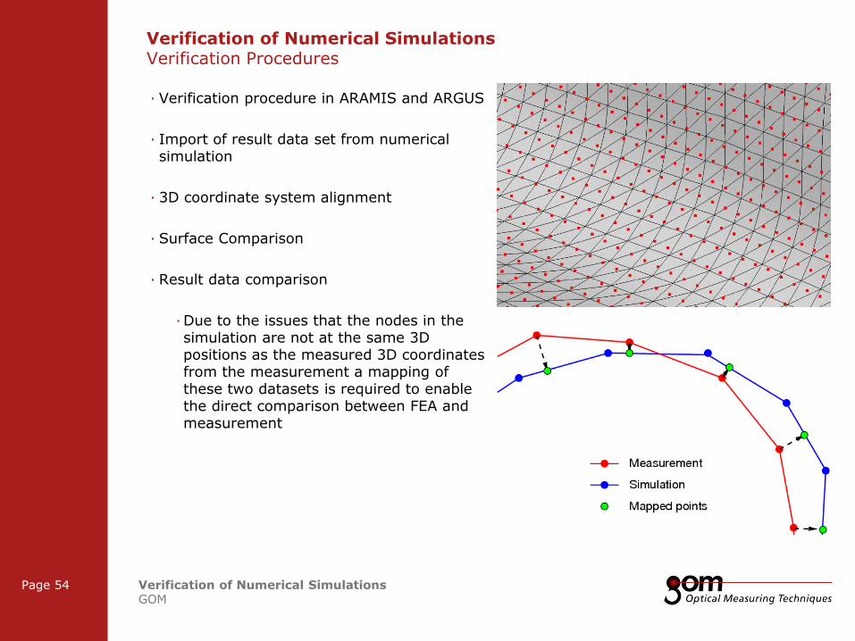
· Result data comparison
· Due to the issues that the nodes in the simulation are not at the same 3D positions as the measured 3D coordinates from the measurement a mapping of these two datasets is required to enable the direct comparison between FEA and measurement
Verification of Numerical Simulations Verification Procedures

2-Frame Setup / Frame 2 2-Frame Setup / Frame 1
3-Frame Setup / Frame 1 3-Frame Setup / Frame 2 3-Frame Setup / Frame 3
Frame 1
Frame 1
Underline 1
Underline 2
Underline 1
Underline 2
Page 55 Verification of Numerical Simulations GOM
Frame 2
Frame 2 Frame 1
Column 1 Column 2
Column 3 Column 1 Column 2
Content
Content
· Verification procedure in ARAMIS and ARGUS
· Import of result data set from numerical simulation
· 3D coordinate system alignment
· Surface Comparison
· Result data comparison
· Due to the issues that the nodes in the simulation are not at the same 3D positions as the measured 3D coordinates from the measurement a mapping of these two datasets is required to enable the direct comparison between FEA and measurement
Verification of Numerical Simulations Verification Procedures
2-Frame Setup / Frame 2 2-Frame Setup / Frame 1
3-Frame Setup / Frame 1 3-Frame Setup / Frame 2 3-Frame Setup / Frame 3
Frame 1
Frame 1
Underline 1
Underline 2
Underline 1
Underline 2
Page 56 Verification of Numerical Simulations GOM
Frame 2
Frame 2 Frame 1
Column 1 Column 2
Column 3 Column 1 Column 2
Content
Content
· Verification procedure in ARAMIS and ARGUS
· Import of result data set from numerical simulation
· 3D coordinate system alignment
· Surface Comparison
· Result data comparison
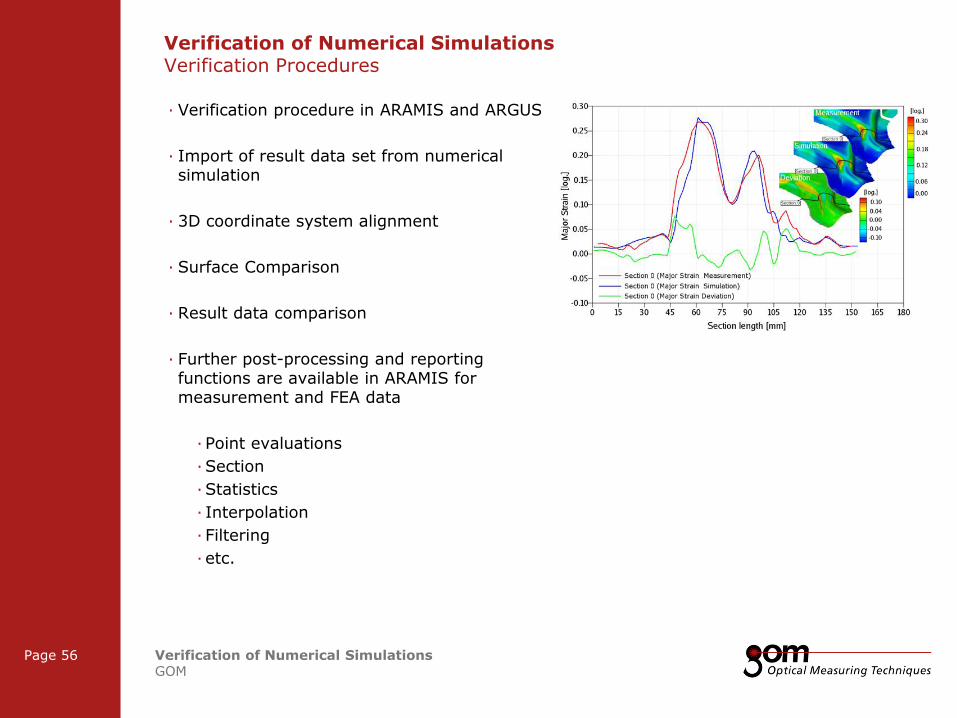
· Further post-processing and reporting functions are available in ARAMIS for measurement and FEA data
· Point evaluations
· Section
· Statistics
· Interpolation
· Filtering
· etc.
Verification of Numerical Simulations Verification Procedures
Frame 1
Frame 1
Underline 1
Underline 2
Underline 1
Underline 2
Frame 2
Frame 2 Frame 1
Column 1 Column 2
Column 3 Column 1 Column 2
Content
Content
Left Line Title
Upper Line Title
Right Line Title
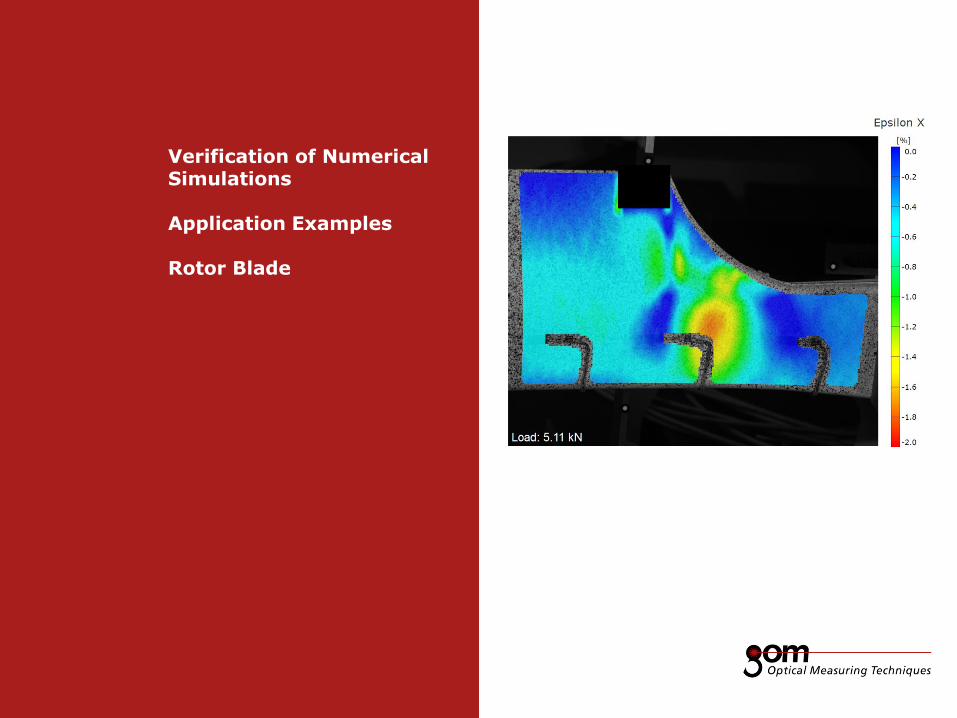
Verification of Numerical Simulations Application Examples Rotor Blade
2-Frame Setup / Frame 2 2-Frame Setup / Frame 1
3-Frame Setup / Frame 1 3-Frame Setup / Frame 2 3-Frame Setup / Frame 3
Frame 1
Frame 1
Underline 1
Underline 2
Underline 1
Underline 2
Page 58 Verification of Numerical Simulations GOM
Frame 2
Frame 2 Frame 1
Column 1 Column 2
Column 3 Column 1 Column 2
Content
Content
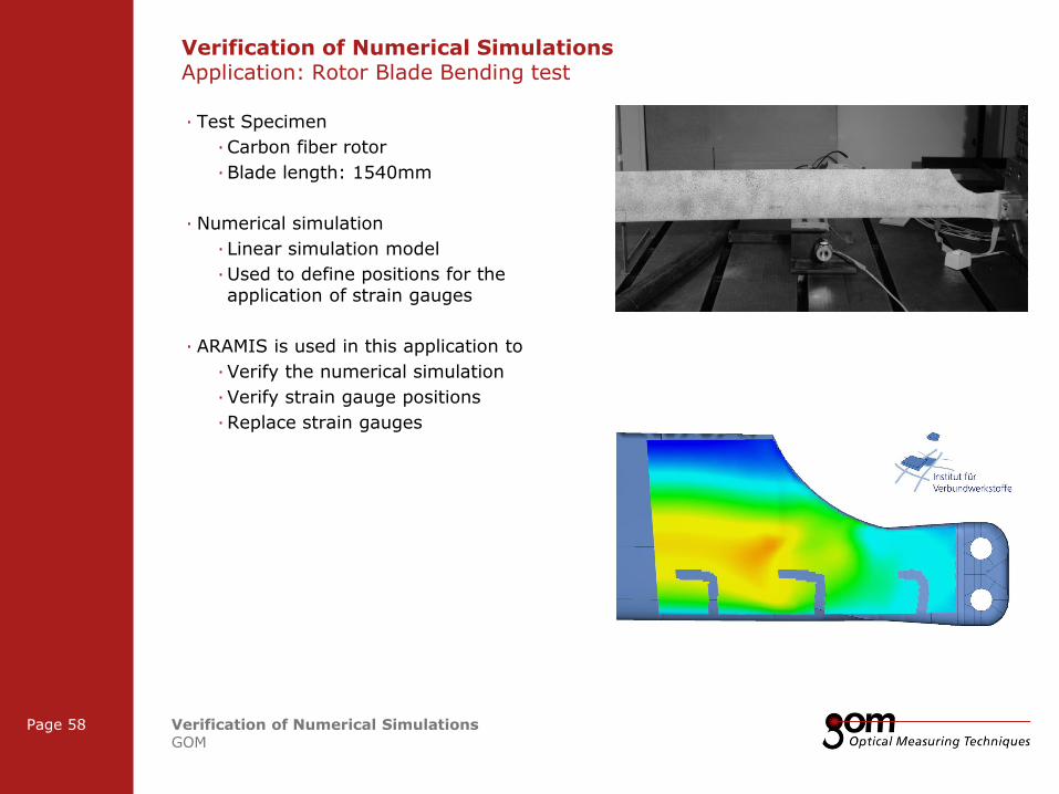
· Test Specimen
· Carbon fiber rotor
· Blade length: 1540mm
· Numerical simulation
· Linear simulation model
· Used to define positions for the application of strain gauges
· ARAMIS is used in this application to
· Verify the numerical simulation
· Verify strain gauge positions
· Replace strain gauges
Verification of Numerical Simulations Application: Rotor Blade Bending test
2-Frame Setup / Frame 2 2-Frame Setup / Frame 1
3-Frame Setup / Frame 1 3-Frame Setup / Frame 2 3-Frame Setup / Frame 3
Frame 1
Frame 1
Underline 1
Underline 2
Underline 1
Underline 2
Page 59 Verification of Numerical Simulations GOM
Frame 2
Frame 2 Frame 1
Column 1 Column 2
Column 3 Column 1 Column 2
Content
Content
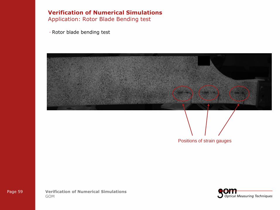
· Rotor blade bending test
Positions of strain gauges
Verification of Numerical Simulations Application: Rotor Blade Bending test
2-Frame Setup / Frame 2 2-Frame Setup / Frame 1
3-Frame Setup / Frame 1 3-Frame Setup / Frame 2 3-Frame Setup / Frame 3
Frame 1
Frame 1
Underline 1
Underline 2
Underline 1
Underline 2
Page 60 Verification of Numerical Simulations GOM
Frame 2
Frame 2 Frame 1
Column 1 Column 2
Column 3 Column 1 Column 2
Content
Content
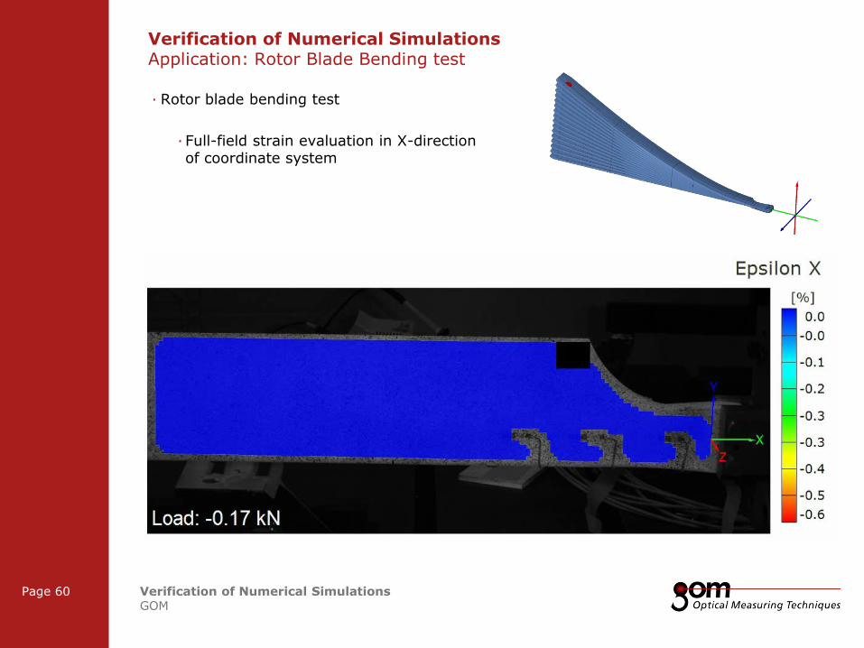
· Rotor blade bending test
· Full-field strain evaluation in X-direction of coordinate system
Verification of Numerical Simulations Application: Rotor Blade Bending test
2-Frame Setup / Frame 2 2-Frame Setup / Frame 1
3-Frame Setup / Frame 1 3-Frame Setup / Frame 2 3-Frame Setup / Frame 3
Frame 1
Frame 1
Underline 1
Underline 2
Underline 1
Underline 2
Page 61 Verification of Numerical Simulations GOM
Frame 2
Frame 2 Frame 1
Column 1 Column 2
Column 3 Column 1 Column 2
Content
Content
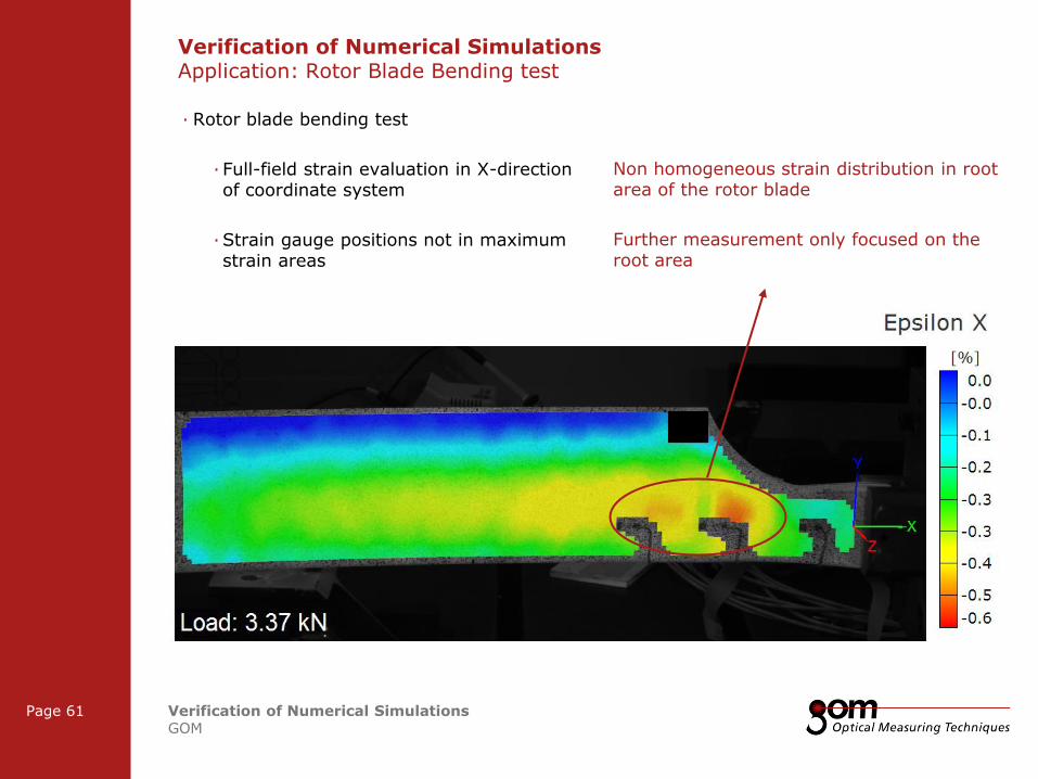
· Rotor blade bending test
· Full-field strain evaluation in X-direction of coordinate system
· Strain gauge positions not in maximum strain areas
Non homogeneous strain distribution in root area of the rotor blade
Further measurement only focused on the root area
Verification of Numerical Simulations Application: Rotor Blade Bending test
2-Frame Setup / Frame 2 2-Frame Setup / Frame 1
3-Frame Setup / Frame 1 3-Frame Setup / Frame 2 3-Frame Setup / Frame 3
Frame 1
Frame 1
Underline 1
Underline 2
Underline 1
Underline 2
Page 62 Verification of Numerical Simulations GOM
Frame 2
Frame 2 Frame 1
Column 1 Column 2
Column 3 Column 1 Column 2
Content
Content
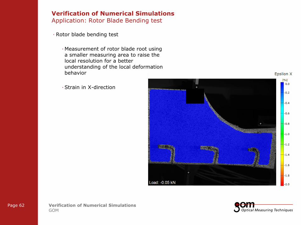
· Rotor blade bending test
· Measurement of rotor blade root using a smaller measuring area to raise the local resolution for a better understanding of the local deformation behavior
· Strain in X-direction
Verification of Numerical Simulations Application: Rotor Blade Bending test
2-Frame Setup / Frame 2 2-Frame Setup / Frame 1
3-Frame Setup / Frame 1 3-Frame Setup / Frame 2 3-Frame Setup / Frame 3
Frame 1
Frame 1
Underline 1
Underline 2
Underline 1
Underline 2
Page 63 Verification of Numerical Simulations GOM
Frame 2
Frame 2 Frame 1
Column 1 Column 2
Column 3 Column 1 Column 2
Content
Content
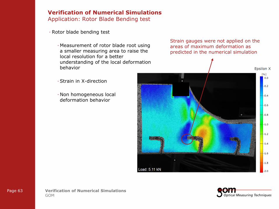
· Rotor blade bending test
· Measurement of rotor blade root using a smaller measuring area to raise the local resolution for a better understanding of the local deformation behavior
· Strain in X-direction
· Non homogeneous local deformation behavior
Strain gauges were not applied on the areas of maximum deformation as predicted in the numerical simulation
Verification of Numerical Simulations Application: Rotor Blade Bending test
2-Frame Setup / Frame 2 2-Frame Setup / Frame 1
3-Frame Setup / Frame 1 3-Frame Setup / Frame 2 3-Frame Setup / Frame 3
Frame 1
Frame 1
Underline 1
Underline 2
Underline 1
Underline 2
Page 64 Verification of Numerical Simulations GOM
Frame 2
Frame 2 Frame 1
Column 1 Column 2
Column 3 Column 1 Column 2
Content
Content
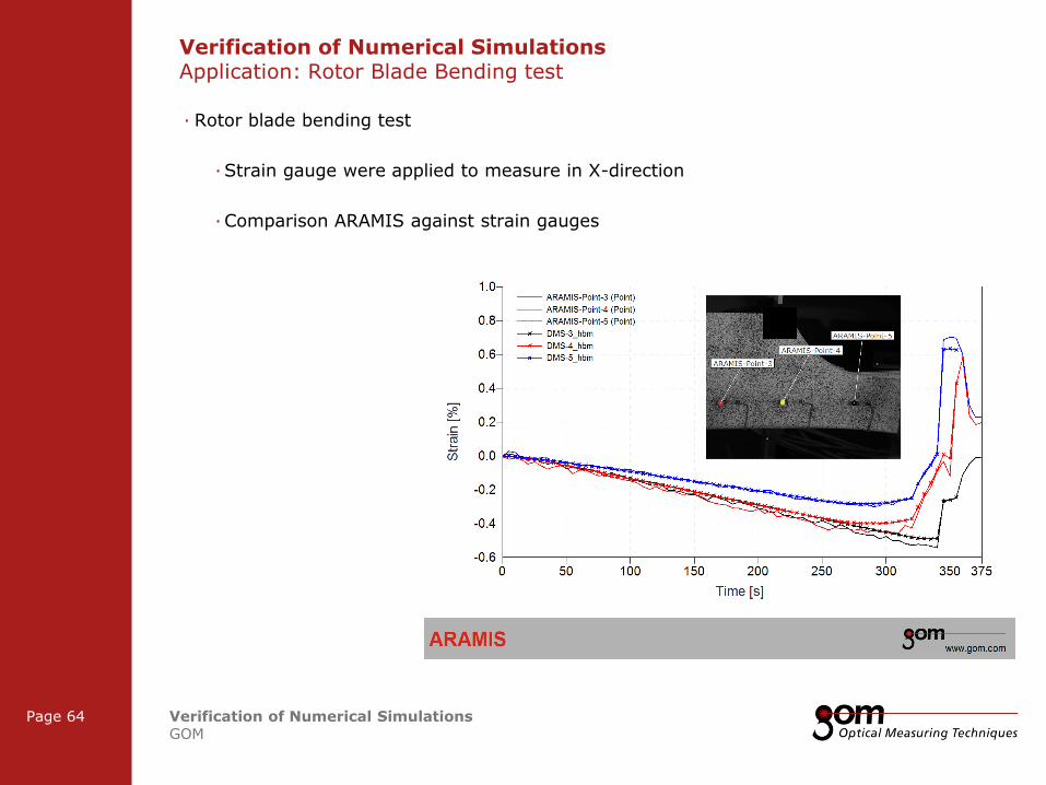
· Rotor blade bending test
· Strain gauge were applied to measure in X-direction
· Comparison ARAMIS against strain gauges
Verification of Numerical Simulations Application: Rotor Blade Bending test
2-Frame Setup / Frame 2 2-Frame Setup / Frame 1
3-Frame Setup / Frame 1 3-Frame Setup / Frame 2 3-Frame Setup / Frame 3
Frame 1
Frame 1
Underline 1
Underline 2
Underline 1
Underline 2
Page 65 Verification of Numerical Simulations GOM
Frame 2
Frame 2 Frame 1
Column 1 Column 2
Column 3 Column 1 Column 2
Content
Content
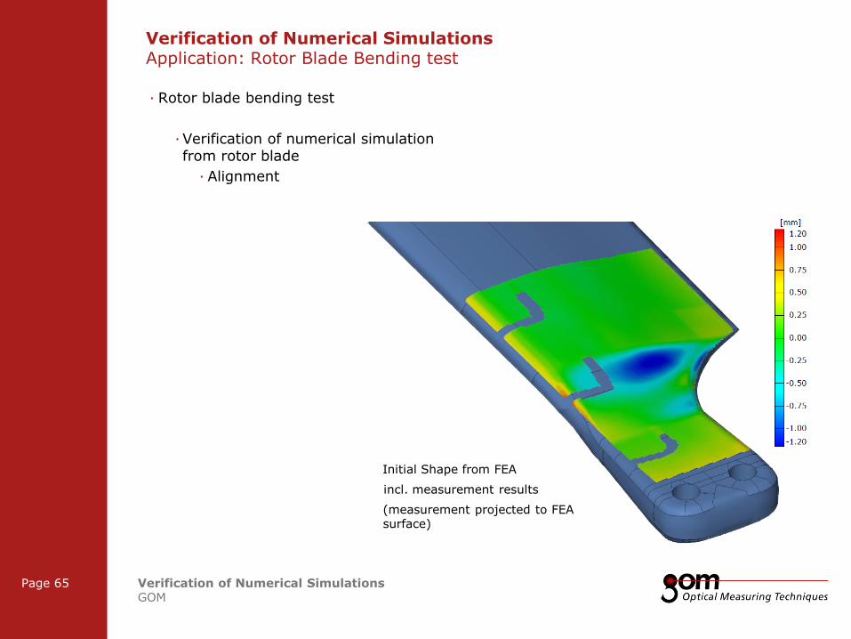
· Rotor blade bending test
· Verification of numerical simulation from rotor blade
· Alignment
Verification of Numerical Simulations Application: Rotor Blade Bending test
Initial Shape from FEA
incl. measurement results
(measurement projected to FEA surface)
2-Frame Setup / Frame 2 2-Frame Setup / Frame 1
3-Frame Setup / Frame 1 3-Frame Setup / Frame 2 3-Frame Setup / Frame 3
Frame 1
Frame 1
Underline 1
Underline 2
Underline 1
Underline 2
Page 66 Verification of Numerical Simulations GOM
Frame 2
Frame 2 Frame 1
Column 1 Column 2
Column 3 Column 1 Column 2
Content
Content
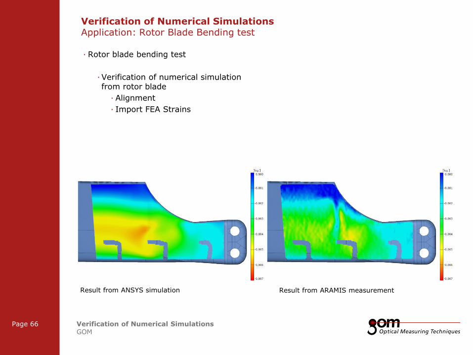
· Rotor blade bending test
· Verification of numerical simulation from rotor blade
· Alignment
· Import FEA Strains
Verification of Numerical Simulations Application: Rotor Blade Bending test
Result from ANSYS simulation Result from ARAMIS measurement
2-Frame Setup / Frame 2 2-Frame Setup / Frame 1
3-Frame Setup / Frame 1 3-Frame Setup / Frame 2 3-Frame Setup / Frame 3
Frame 1
Frame 1
Underline 1
Underline 2
Underline 1
Underline 2
Page 67 Verification of Numerical Simulations GOM
Frame 2
Frame 2 Frame 1
Column 1 Column 2
Column 3 Column 1 Column 2
Content
Content
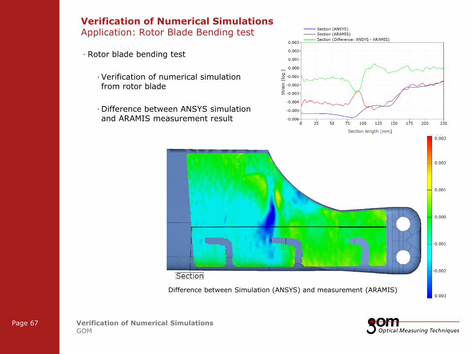
· Rotor blade bending test
· Verification of numerical simulation from rotor blade
· Difference between ANSYS simulation and ARAMIS measurement result
Verification of Numerical Simulations Application: Rotor Blade Bending test
Difference between Simulation (ANSYS) and measurement (ARAMIS)
2-Frame Setup / Frame 2 2-Frame Setup / Frame 1
3-Frame Setup / Frame 1 3-Frame Setup / Frame 2 3-Frame Setup / Frame 3
Frame 1
Frame 1
Underline 1
Underline 2
Underline 1
Underline 2
Page 68 Verification of Numerical Simulations GOM
Frame 2
Frame 2 Frame 1
Column 1 Column 2
Column 3 Column 1 Column 2
Content
Content
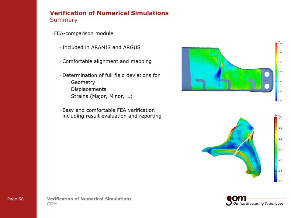
· FEA-comparison module
· Included in ARAMIS and ARGUS
· Comfortable alignment and mapping
· Determination of full field deviations for
· Geometry
· Displacements
· Strains (Major, Minor, …)
· Easy and comfortable FEA verification including result evaluation and reporting
Verification of Numerical Simulations Summary

2-Frame Setup / Frame 2 2-Frame Setup / Frame 1
3-Frame Setup / Frame 1 3-Frame Setup / Frame 2 3-Frame Setup / Frame 3
Frame 1
Frame 1
Underline 1
Underline 2
Underline 1
Underline 2
Page 69 Verification of Numerical Simulations GOM
Frame 2
Frame 2 Frame 1
Column 1 Column 2
Column 3 Column 1 Column 2
Content
Content
Verification of Numerical Simulations Overview Finite Element Simulation
Input Geometry (Mesh)
Material Parameters
FE Verification
Boundary Conditions
Shape
Displacement
Strain
Position
FE Optimization
Meshing

Frame 1
Frame 1
Underline 1
Underline 2
Underline 1
Underline 2
Frame 2
Frame 2 Frame 1
Column 1 Column 2
Column 3 Column 1 Column 2
Content
Content
Left Line Title
Upper Line Title
Right Line Title
Thank you for your attention
www.gom.com