
GOLF IRRIGATION CATALOG 2015media.toro.com/CatalogDocuments/Product Literature/golf_cat.pdfGOLF...
92
GOLF IRRIGATION CATALOG 2015
Transcript of GOLF IRRIGATION CATALOG 2015media.toro.com/CatalogDocuments/Product Literature/golf_cat.pdfGOLF...

GOLF IRRIGATION CATALOG 2015

A CENTURY OF INNOVATION
Since July 10, 1914, a long line of ingenious Toro inventors have developed dramatic breakthroughs that helped establish and strengthen the Company’s leadership role and revolutionize the industries in which we compete.
As we enter our second century, the people of Toro will continue to lead with our relentless drive to innovate. At Toro, innovation is more than a slogan; it is our lifeblood, our legacy, our commitment to all the customers we are honored to serve.
By celebrating our past, we reveal our future. Yesterday, today and tomorrow, The Toro Company’s fundamental commitment to building long-term customer relationships based on integrity and trust, transcends time.
Our high-quality products and legacy of trusting relationships has combined to make Toro the leading global supplier of innovative turf maintenance equipment and precision irrigation solutions to the golf market. Our products are used to maintain a vast number of public, private, municipal, and resort golf courses-including many of the world’s top golf venues.
The strength of any institution rests solely in the good will of the people with whom they deal. You can replace anything except the good will of your customers.
~John Samuel Clapper, Co-Founder and First President
The success of this company is no secret. It has been due to two simple things: building a good product, and treating customers honestly and fairly. The only way to success is by the fair and honest treatment of customers.
~Kenneth E. Goit, Toro’s Third President
Our purpose is to help our customers enrich the beauty, productivity and sustainability of the land. This is our legacy, our purpose, our commitment to both the customers we serve and the generations to come.
2

3
Lynx, Field Controllers & Sprinklers Overview 4-9
Irrigation Services 10
CONTROL SYSTEMS & FIELD CONTROLLERSField Controller Comparison Chart 11
Lynx® Central Control 12-13
Turf Guard® Wireless Soil Monitoring System 14-15
Hand-held Radio Interface 16
Radio Interface Unit (RIU) & FIU with Radio 16
NSN® (National Support Network) 17
Network VP® Satellites 18-19
E-OSMAC®, OSMAC RDR Satellites 20-21
GDC 2-Wire System 22-23
SPRINKLERS & SUBSURFACE DRIPSprinkler Comparison Charts 24-25
INFINITY® Series Rotors 26-37
FLEX800™ Series Rotors 38-49
FLEX800™ B Series Rotors 50-53
Main Nozzle Adaptor Performance Charts 54-55
FLEX800™ R Series Conversion Upgrades 56-58
Toro® Conversion Upgrades 57
Back & Mainless Nozzle Data 59
T7 Rotor 60-61
690 Series Rotors 62-63
590GF Sprays 64-65
Precision™ Rotating Nozzles 66-67
Precision™ Spray Nozzles 68-71
Subsurface Drip 72-73
Toro® Swing Joints 74-75
Sprinkler Tools 76
VALVESValve Comparison Chart 77
220G Brass Series 78-79
P220G and P220GS Series 80-81
Toro® Valve Boxes 82-83
Toro® Dry Boxes 84
Quick Couplers 85
GOLF LIGHTINGTwilight™ Golf Cup & Perimeter Lighting 86-87
RESOURCESTechnical Data 88
Wire Sizing 88
Warranty 89
Distributor Map and List 90-91
TABLE OFCONTENTS

LYNX® CENTRAL CONTROL SYSTEM OVERVIEW
More information & demo video on
www.toro.com/lynx
BETTER INFORMATIONFOR BETTER DECISIONS
The Toro® Lynx® Central Control System was developed specifically to help you address the unique challenges and changing priorities you face every day. With Lynx, you can now have all of your essential irrigation information readily available in one place, conveniently combined into a single, intuitive interface.
Easy to UseLynx® has a distinct user interface that combines all essential data and intuitively presents the information you need (alerts, scheduled watering and more) at a glance. It’s easy to access all the information you need with one click through your Favorites Menu.
Easy to Control Lynx® empowers you to take quick, accurate action to effectively control and manage your golf course by providing past, present and future course information from multiple sources into a single, intuitive interface.
National Support Network (NSN®)Toro’s exclusive National Support Network provides software and network assistance from experienced service professionals who understand what you need. NSN Connect™ allows easy remote access to your irrigation system.
Easy to Set UpLynx® was developed for quick setup – it gives you a fast, accurate way to setup your system to put water exactly where you want it, and then allows you to make edits as your course conditions change.
4
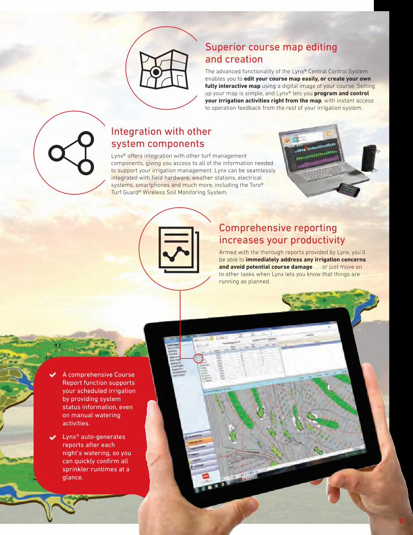
Integration with othersystem componentsLynx® offers integration with other turf management components, giving you access to all of the information needed to support your irrigation management. Lynx can be seamlessly integrated with field hardware, weather stations, electrical systems, smartphones and much more, including the Toro® Turf Guard® Wireless Soil Monitoring System.
Comprehensive reporting increases your productivityArmed with the thorough reports provided by Lynx, you’ll be able to immediately address any irrigation concerns and avoid potential course damage . . . or just move on to other tasks when Lynx lets you know that things are running as planned.
A comprehensive Course Report function supportsyour scheduled irrigation by providing system status information, even on manual watering activities.
Lynx® auto-generates reports after each night’s watering, so you can quickly confirm all sprinkler runtimes at aglance.
Superior course map editing and creationThe advanced functionality of the Lynx® Central Control System enables you to edit your course map easily, or create your own fully interactive map using a digital image of your course. Setting up your map is simple, and Lynx® lets you program and control your irrigation activities right from the map, with instant access to operation feedback from the rest of your irrigation system.
5

More information on
www.toro.com/golf
FIELD CONTROL SYSTEMS – Integrate Seamlessly with Lynx®
6
Advanced 2-Wire ControlIntelligent 2-wire modules can be installed inside the sprinklers or off-fairway.
TORO FIELD CONTROL SYSTEMS Toro is the World's leading golf irrigation company
and provides an array of field control options
Satellite ControlSatellite systems use controllers placed on each hole to operate a specified number of stations.
Custom pedestal colors enable satellites to blend into the natural surroundings.
Hardwire, 2-way radio and paging communication options allows for easy installation and maintenance.
Future upgrades can be accomplished with advanced satellite firmware, keeping you current with technology.
Satellite upgrade kits enable older Toro satellite units to be upgraded very cost effectively vs. a complete system change-out.
Sturdy Plastic PedestalsAvailable in Sand, Tree Bark or Green.
Continuous two-way communication
Real time diagnostics and voltage tests
Best-in-class broadband lightning protection
Vandal and flood resistant
Allows for system expansion by tapping into the cable
Toro INFINITY® and FLEX800™ Series sprinkler models have an integrated 2-wire module option

The Lynx® Central Control System offers integration with Toro’s Field Control Systems, enabling you to have the complete information needed to support your irrigation decisions.
Lynx® for GDC
7
While others have followed in our footsteps, Toro is the industry leader in advanced 2-wire systems.

More information & demo video on
www.toroinfinity.com
8
TORO® GOLF SPRINKLERS
The new INFINITY® Series improves your course quality with less workload and most important, it keeps players playing. Calculate the money you’ll save by cutting sprinkler maintenance from hours to minutes.
INFINITY® SERIES GOLF SPRINKLERS Engineered for Today’s Challenges.
Designed for Tomorrow’s Technologies.
Smart Access®
Provides top accessibility to all critical components.
No digging or unsightly turf repair scars
Pilot valve removable with water “ON”
GDC 2-wire module accessible from the top
Customizable marker
No buried wire splices or ground faults
Replaceable cover if damaged
Increased labor efficiency
Lower long term cost of ownership
Protective EnclosureThe protective enclosure isolates wire splices from the soil and potential shorts to ground. Provides access for system troubleshooting and repairs without digging!
Future ProofThe SMART ACCESS® compartment provides room to grow. Whatever the future holds, this sprinkler will be ready.
9
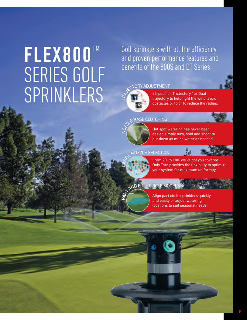
FLEX800™ SERIES GOLF SPRINKLERS
Golf sprinklers with all the efficiency and proven performance features and benefits of the 800S and DT Series
24-position TruJectory™ or Dual trajectory to help fight the wind, avoid obstacles or to or to reduce the radius.
TRAJ
ECTORY ADJUSTMENT
NOZ
ZLE BASE CLUTCHING
LARG
E NOZZLE SELECTION
PART
AND FULL CIRCLE MODELS
Hot spot watering has never been easier, simply turn, hold and shoot to put down as much water as needed.
From 20’ to 100’ we’ve got you covered! Only Toro provides the flexibility to optimize your system for maximum uniformity.
Align part circle sprinklers quickly and easily or adjust watering locations to suit seasonal needs.

Toro Technical SupportOur technical support team is highly skilled at what they do. From helping
superintendents, program controllers, to troubleshooting complex system issues with
consultants, the support team provides years of irrigation experience that you can count
on. For exceptional technical support, call 1-877-345-TORO (3626).
Toro Controller RepairDid you know that with Toro’s Board Exchange Program you can get the replacement
controller boards you need immediately? Through your distributor, Controller Repair
provides controller boards ready for immediate board exchange to assure that
controller downtime is minimal and your golf course and reputation stays protected.
For immediate assistance call: 1-877-345-TORO (3626).
Visit Controller Repair website at www.toro.com/controller-repair
Toro Distributor SupportOur distributors have been our partners for an average of 40 years (10 to 88 years) and
we consider them an extension of us.
Toro Field ServiceWith some of the most knowledgeable and helpful field service staff in the industry, and
our extensive training and support programs; Toro field service personnel are always
there to assist—before, during, and well after a sale.
Toro Genuine PartsFrom the smallest sprinkler part to complete control systems, Toro Service Parts
support can deliver most replacement parts to our distributors within hours. In fact,
Toro offers its customers the highest parts order completion rate in the industry: 98%!
Toro FinancingBy offering a variety of customized, competitive financing plans, Toro gives you
“one-stop shopping” eliminating the need for third-party funding. You can improve
your course without draining your budget.
Toro National Support Network (NSN®)A team of A+ certified technicians and licensed irrigators dedicated to the daily
operations and maintenance of computerized central control systems for customers
worldwide. (see page 17 for more information)
10
TORO SUPPORT

Field Controller Comparison Charts
Feature/Capability Network VP® E-OSMAC® OSMAC® RDR GDC
Catalog Pages 18-19 20-21 20-21 22-23
Maximum Station Per Controller 64 64 48 1600
Maximum Simultaneously Operating Stations
Per Controller32 16 16 200
Stand-alone Programs 64 24* 24* 10**
Wireline Field Communication Yes No No Yes
Wireless Field Communication Yes Yes Yes Yes***
Upload Field Changes Yes No No No
Field Controller Alerts Yes No No Yes
Downloaded Programs Yes No No Yes***
Station Based Flow Management Yes Yes Yes Yes
Station Current Sensing Yes No No No
Station Runtimes In Seconds Yes Yes Yes No
* Requires Smart OSMAC** GDC 200 Stand-alone Gateway
*** GDC Remote
Lynx® CentralControl System
Pages 12-13 Turf Guard®
Pages 14-15
11
CONTROL SYSTEM AND FIELD CONTROLLERS

12
The Toro® Lynx® Control System was developed specifically to help you address the unique challenges and changing priorities you face every day. With the Lynx System, you can now have all of your essential irrigation information readily available in one place, conveniently combined into a single, intuitive interface.
Integrated Turf Guard® Soil Sensor InformationHelps you determine when to irrigate and how much which helps you save water.
Lynx MobileEnables remote access and control from any mobile device connected to the Internet. Screens are specifically designed and optimized for smaller devices.
Lynx 3.1 Adds More Flexibility and More ControlStation Percent Adjust for duration allows you to set temporary
adjustments that automatically returns to normal after a set
number of days. The new Sequential Instant Program allows
you to pick the order stations water automatically. GDC system
diagnostics can now be selected by Hole or Area to make pin
pointing a problem even easier, and you can now chose to have
Lynx automatically upload station changes into the Watering Plan.
Simplified Decision Making with Dynamic Drilldown Guides you to where you need to go. Follow the water drop in
the Watering Plan to find stations, holes or entire areas that are
disabled, on hold or otherwise not programmed to irrigate. Quickly
find any stations in Course Report that did not operate as intended.
Flexible and Editable MapEasily add, drag, drop and assign sprinklers, satellites, sensors and
switches to their exact locations. You can effortlessly make edits as
your field hardware changes. Fully supports CAD-generated maps.
Power Guard Helps Prevent Wasted Energy Integration with a Flowtronex® pump station with PACE™ enables
the exclusive Lynx Power Guard feature to track and control
electricity usage of the system.
LYNX® CENTRAL CONTROL SYSTEM
FEATURES & BENEFITS

13
NSN® ConnectRemote access so that you can control irriga-tion anytime, anywhere.
ADDITIONAL FEATURESRuntimes:• Runtimes are executed to the second rather than rounding to the
whole minute, resulting in more precise irrigation and water savings (Network VP® & OSMAC® only)
• Control your irrigation by setting runtime minutes or application inches and let the system calculate the other. See exactly how much water you will apply and how long you will irrigate each area
• Runtime synchronization with Network VP satellites prevents irrigation outages if the central goes offline
• Integrated runtime display shows past and planned irrigation activity so you can easily determine what action to take
Quick Start:• With Quick Start, you create station, hardware and area associations,
and control the definition of greens, tees, fairways and sprinklers based on the their locations
• A basic hydraulic tree is auto-generated for you during Quick StartViews and Reports:• Course Report provides both real time and daily summaries of both
scheduled and manual watering events• Area and Hole orientation allows you to control your irrigation system
the same way you think about the course• Instant Program has simple check-box selection and Dynamic
Drilldown to you can instantly create and personalize new irrigation programs
• Projected Flow View shows you areas that will be watered and how much will be applied
Communication:• Current-sensing capabilities notify you of wire cuts and sprinklers
unintentionally turned off (Network VP Only)• Constant communication with Network VP satellites lets you take
action if a power outage threatens irrigation• Toro GDC communication and solenoid diagnostics help identify
shorts, low voltage and other issues• Weather station integration and Hand-held Remote Interface support
are included as standard featuresOperating System:• Windows 7
Specifying Information—Lynx CE Central Upgrade for SitePro®
Model Description
LYNX-NSN-STANLYNX-NSN-PREMLYNX-NONNSN-STANLYNX-NONNSN-PREMLX-SW
Lynx Upgrade - NSN – Standard Toro Computer Lynx Upgrade - NSN – Premium Toro Computer Lynx Upgrade-NSN-Standard Computer and 1-year NSN SupportLynx Upgrade-NSN-Premium Computer and 1-year NSN Support Software, Lynx, Client/Server
Specifying Information—Lynx Central
LX-0X-X-XXModel Computer Hardware Service Levels Field Hardware
LX 0X X X X
LX-LYNX Central Control 1—Standard Computer4—Premium Computer
1—1-year NSN5—5-years NSN
O—CE 1—SE 2—PE
1—For OSMAC7—For Network VP8—For Network GDC
Example: When ordering a LYNX Central standard computer with one year of NSN and CE Level with Network VP field hardware, you would order: LX-01-1-07
SPECIFICATIONS – Lynx® Levels ComparisonSYSTEM CAPACITY Lynx CE Lynx PE Lynx SE
Satellites 500 500 500
Satellites Stations 32,000 1344 512
GDC Stations 6400 1000 500
Weather Stations 10 10 10
Pump Stations 10 3 2
Courses 3 2 1
Holes 84 56 28
Hydraulic Branches 1024 300 100
HARDWARE SUPPORTED
OSMAC® Yes Yes Yes
Network GDC Yes Yes Yes
Network VP® Yes No No
PROGRAMMING
VP Current Sensing Yes No No
VP Station Adjust Upload Yes No No
Site Code Categories 7 3 No
Precip. Mgmt. Groups (PMG) Yes Yes No
Max. Stations/Hole Control Yes Yes No
Instant Program Creation Yes Yes Yes
Program Priority Yes Yes No
Pump Profiling Yes No No
Station Group Multi-Manual Yes No No
Master Group Multi-Manual Yes No No
Pump Integration Yes Yes Optional
Weather Station Alarms Yes Yes Optional
ET Auto Calc. RT Method Yes Yes Optional
NSN ConnectRemote Access Through A Trusted Partner
LYNX® CENTRAL CONTROL SYSTEM

14
Get the essential soil information you need, when you need it. Stay up to date on your current soil conditions no matter where you are. Get the information you need to make important decisions in real time. Turf Guard sensors instantly track soil moisture, salinity, and temperature, saving you time. Repeaters mount easily inside all Toro Network VP®, Network LTC® Plus and E-OSMAC® satellite pedestals.
Reduce Water Usage and Improve PlayabilityMonitor moisture levels and adjust irrigation without risking turf
quality. Promote root growth by avoiding over watering. Detect
dry areas before they impact the turf’s health.
100% Wireless NetworkNo wires between the repeaters and the sensors, or the sensor
and the probes means that sensors can be installed anywhere on
the course without disrupting play. Install sensors without having
to trench or pull wires.
Take the Guesswork out of Managing SalinityTrack salt build-up and schedule flushing as needed. Get positive
confirmation that your flushing reduced soil salts. Know when and
how much water to flush with.
TURF GUARD® WIRELESS SOIL MONITORING SYSTEM
FEATURES & BENEFITS
Web-based or Stand-alone InterfaceGraphical course overview displays sensor data at-a-glance. Plus with Toro Lynx® Control System integration you can check course moisture, salinity and temperature readings right from your irrigation control software.

15
ADDITIONAL FEATURESOperational• Two distinct depths in the soil profile – critical root zone level and a
second 5” lower. Independent measurements from each depth.• MESH routing technology offers complete coverage even in remote
canyon courses.• Repeater mounts in most Toro irrigation satellite pedestals. An external
repeater is available for other models including non-Toro pedestals.• Supports up to 500 sensors per course• Expected sensor battery life of 3 years, field replaceable.• Sensor reading sent every 5 minutes.• Automatic network configuration and failure recovery.• Plots trends and compares historical and current readings.• Lynx® Control System integration
ElectricalInput Power: - Repeater: <.02A @ 6 VDC - Base Station: <.1A @ 120 VAC, 50/60 Hz• UL and CE approvedDimensions:• Body: 2” x 3” x 5”• Spikes: 2.5” x 3/16”• Installation Hole Diameter: 4.25”Temperature:• Operating: 32º F to 140º F• Storage: -22º F to 180º FSensing:• 0.1°F temperature resolution• 0.1 % volumetric soil moisture content resolution• 0.1 dS/m soil conductivity resolution (salinity)Communication:• Repeater Range: 2,000’ line-of-sight• Buried Sensor Range: 500’ line-of-sight• 900 MHz ISM Band FHSS communication• Additional licensing not required
Specifying Information—Turf GuardModel Description
TG-S2-RTG-R-INTTG-R-EXT
TG-BTG-S2-BAT
Turf Guard Sensor With Replaceable BatteryRepeater-Internal MountRepeater-External Mount
Base StationSensor Replacement Battery
HOW IT WORKS…
Three to five sensors buried in each green at critical root zone levels
Additional sensors buried in fairways, tee boxes and planters
Above-ground radio repeaters installed on or in existing irrigation pedestals
Wireless MESH networking links all sensors to central control system
Moisture, Temperature and Salinity readings displayed in your office

CONTROL SYSTEM ACCESSORIES
16
Specifying Information—Field Interface Unit (FIU) Model Description
FIU-2011FIU-2011RFIU-2021FIU-2021R
Field Interface Unit with 1 Wire Line & 1 Radio Line, Radio Not IncludedField Interface Unit with 1 Wire Line & 1 Radio Line, Radio IncludedField Interface Unit with 2 Wire Lines & 1 Radio Line, Radio Not IncludedField Interface Unit with 2 Wire Lines & 1 Radio Line, Radio Included
Note: FCC license required.
Specifying Information—Radio Interface Unit (RIU)
Model Description
RIU-00RIU-01RIU-02
Radio Interface Unit – External RadioRadio Interface Unit – Single RadioRadio Interface Unit – Dual Radio
Note: FCC license required.
Radio Interface Unit (RIU) Graphical User Interface.
Radio Interface Unit (RIU)The Toro® Radio Interface Unit combines the functions of the
OSMAC® Base Station and Hand-held Remote Interface (HHRI) in
a single unit. Available in a dual radio configuration that performs
both Base Station and HHRI functions, a single radio configuration
that’s programmable for either function, and a radio-less
configuration that’s programmable for either function and utilizes
a user-supplied external radio for added flexibility.
Network Radio-Link and FIU with RadioNetwork Radio-Link offers you the flexibility to design your
irrigation system unconfined by the limitations of distance
or terrain. Oversized acreage and natural barriers are not a
problem for Network Radio-Link. Communicating where wires
can't run, it's the bridge between non-contiguous wire line
systems and much more.
Provides control of your system while you're on-the-go
Provides both hand-held control and central-to-satellite communication
Designed to operate continuously, 24/7
Interfaces with your Lynx® or SitePro® central without the burden of recurring network costs
Tailored to fit your application with programmable selections for: OSMAC Base Station and hand-held remote interface modes, independent transmit/receive UHF frequencies, independent transmit/receive private line settings (CTCSS) and transmit power.
Wireless communication to Network satellites
Network Radio-Link kits for upgrades
True 2-way communication
Multi-port field interface allows one radio to be shared among many satellites
Easy satellite installation
Compatible with Network LTC® Plus and Network VP®
FEATURES & BENEFITS
FEATURES & BENEFITS

17
Before, during and after the purchase of your Toro central control system, we pledge to support all of your needs with our National Support Network, Toro NSN® has been taking care of customers since 1991. From small system upgrades to large-scale golf applications, our knowledgeable staff, including bilingual representatives, is available to assist you over the phone 24/7, every day of the year. Our technicians are licensed irrigation specialists and can link directly to your system’s computer to perform remote diagnostic checks and offer expert advice. If necessary, we can send you a replacement computer within 24 hours. Support subscriptions to Toro NSN are included with the purchase of a Toro central control system and can be renewed for extended periods after this initial subscription. NSN Connect provides remote access and our latest offering and NSN Connect Plus allows remote monitoring of your system. The NSN Customer Portal is your one-stop-shop for anything and everything dealing with your NSN relationship.
NSN® Connect for Lynx® and SitePro®
Features• Remote access so that you can control Irrigation anytime, anywhere• Easy access from your desktop, laptop, or mobile device• Ability to easily transfer files• Ability to print remote documents from a remote location
Minimum Requirements for Remote Control Devices• Desktop or Laptop - Windows 7 (or later) or Mac OSX 10.7 (or later) - Modern web browser (Internet Explorer 9+, Chrome, Safari, Firefox)• Tablet or Smart Phone - Apple (iOS), Android, or Windows 8.x - Any modern mobile web browser (Internet Explorer 10+, Chrome, Safari, Firefox)
NSN® Customer Portal*Features• Access your irrigation computer via your NSN Connect account• View the status of your recent Orders and Shipments• Chat with an NSN Technician• View the status of your NSN service(s)• See what service renewal options are available to you• Watch training videos and view other training resources• Access the NSN Technical Knowledge Base• Tell us what kind of emails you would, and would not, like to receive from NSN
*Coming in 2015
NSN® Connect Plus for LynxFeatures• Adds remote hardware and software monitoring to NSN Connect• Automatic notifications via Email and Txt• Proactive support and computer hardware replacement from NSN
Specifications• Platform – Toro® Lynx control system• Operating System – Windows 7 (64-bit)• User Configuration - Ability to have multiple email/txt recipients for alert notifications - Ability to set a schedule (days and times) of when to receive alert notifications - Ability to enable/disable specific monitors - Ability to have alerts sent to different recipients for different monitors• Monitors - Toro Lynx Control System Software - Computer Hardware• High speed Internet access required at the Irrigation computer
We're Always Here for You! NATIONAL SUPPORT NETWORK (NSN®)

18
The Network VP® satellite from Toro® combines modular flexibility, ease of use and increased control in a single controller. With individual station runtimes programmed to the second and station-based flow management, the Network VP provides the most water efficient capabilities for irrigating.
Station Based Flow ManagementReduces nighttime water window and optimizes pump capacity.
Central irrigation programs (greens, tees, etc.) are available from
the satellite faceplate for manual watering and field adjustments.
Reduced Download TimeVariable Length (VL) communication reduces download time by up
to 80%. Communicate all program information to field controllers
in minutes.
Current Sensing Provides ProtectionMonitors each station output for proper amperage draw with user
defined thresholds. Under and over current alarm notification
protects against electrical shorts, wire cuts, etc.
Runtime In Seconds For More Precise WateringStation runtimes are executed to the second. This prevents
individual stations from over or under watering by up to 25%
compared to systems that operate only in whole minutes.
NETWORK VP® SATELLITES
FEATURES & BENEFITSIntuitive User Interface With backlit display for better low-light viewing. Station range entry makes establishing irrigation routines easier. DVD type controls for Start, Pause/Resume and Stop.

19
Upgrade Kit – Network LTC® Plus to Network VPUpgrade kits include a faceplate, power distribution board, and interface cable. Full installation can be completed in minutes per controller.
SPECIFICATIONSOperational• Operates as a stand-alone controller, or under the management of a
central computer - Supports wireline or radio communications - Supports hybrid communication (wireline & radio) • 64 irrigation programs• Basic, Advanced and Grow-in programs• Percent adjust from 1% to 900% • Each output can be defined as an irrigation station or general
application switch• Non-volatile memory retains program information and satellite
settings during power-off conditions. Battery back-up retains the date and time.
• 16-64 stations in 8-station increments – individual station control and the ability to run up to 32 stations simultaneously
• Backwards compatible with Toro Network 8000 satellites
ElectricalInput Power:• 108 V ac to 132 V ac, 60 Hz - 0.20 amps (no load) 115 V ac - 1.20 amps (max load) 115 V ac• 216 V ac to 264 V ac, 50 Hz - 0.10 amps (no load) 230 V ac - 0.60 amps (max load) 230 V ac
Output Power:• 24 V ac - 3.0 amps (max total load)• UL Listed
Dimensions• Plastic Cabinet: 17” W x 40” H x 16” D
Temperature/Humidity• Operating Temperature: -15º F to 140º F• Storage temperature: -22º F to 149º F• Humidity: 0% to 95% RH (non-condensing)
Options• Surge Protection
Specifying Information—Network LTC Plus Upgrade Kit118-0038
Kit ContainsNetwork VP Faceplate, Network LTC Plus To Network VP Power Distribution Board, Cable And Hardware
Specifying Information—Network VP Satellites201-XXX6XX
Description Configuration Cabinet Output Comm. Options
201 XX X 6 X X
201—Network VP Satellite
16—16 Stations 24—24 Stations32—32 Stations 40—40 Stations48—48 Stations 56—56 Stations64—64 Stations
P—Plastic, GreenT—Desert SandB—Tree Bark
6—24 VAC Electric A—Stand-aloneM—2-Way Wire ModemR—UHF Radio
3—Large-capacity Terminal Block & Switches4—Large-capacity Terminal Block w/Add’l Surge & Switches
Example: When ordering a 24-station, Stand-alone VP Satellite in a plastic cabinet with large-capacity terminal block, additional surge and switches, you would specify: 201-24P6A4

20
The E-OSMAC satellite is easy to install, troubleshoot and maintain. Economical because you buy only what you need and can expand as your site conditions change. They utilize paging technology to create one of the most convenient, dependable, and flexible satellites on the market. Employing wireless communication, these satellites are great for retrofit projects.
Low Cost Wireless CommunicationIdeal choice for upgrading existing systems. No communication
wires are needed. Mounts to many existing pedestal bolt patterns.
Easily ExpandableE-OSMAC offers up to 64 stations in eight-station increments. The
OSMAC RDR is expandable from 16 to 48 stations.
Lower Operating CostsThe enhanced surge protection on E-OSMAC and electric OSMAC
RDR provide lower operating costs. Ideal for high lightning areas.
Flexible Station OutputsAvailable with either electric or hydraulic station outputs.
Combine satellites with different output types for added system
flexibility.
E-OSMAC® AND OSMAC RDR SATELLITES
FEATURES & BENEFITS
21
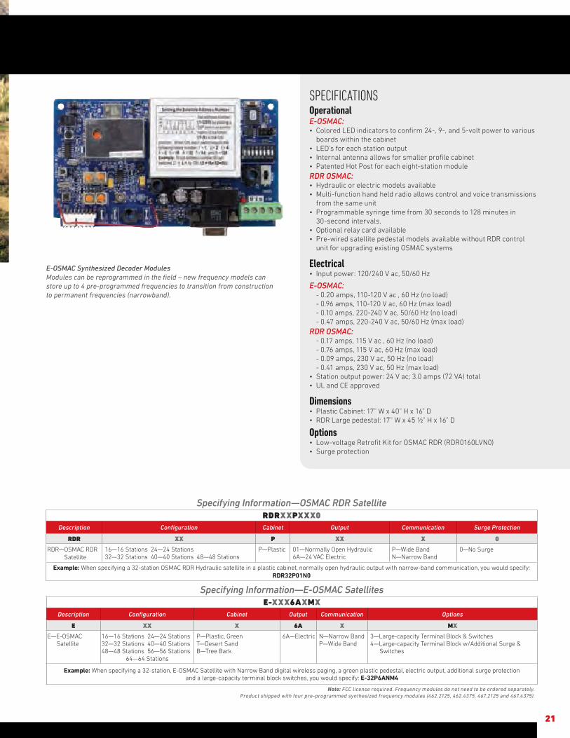
SPECIFICATIONSOperationalE-OSMAC:• Colored LED indicators to confirm 24-, 9-, and 5-volt power to various
boards within the cabinet• LED’s for each station output• Internal antenna allows for smaller profile cabinet• Patented Hot Post for each eight-station moduleRDR OSMAC:• Hydraulic or electric models available• Multi-function hand held radio allows control and voice transmissions
from the same unit• Programmable syringe time from 30 seconds to 128 minutes in
30-second intervals.• Optional relay card available• Pre-wired satellite pedestal models available without RDR control
unit for upgrading existing OSMAC systems
Electrical• Input power: 120/240 V ac, 50/60 Hz
E-OSMAC: - 0.20 amps, 110-120 V ac , 60 Hz (no load) - 0.96 amps, 110-120 V ac, 60 Hz (max load) - 0.10 amps, 220-240 V ac, 50/60 Hz (no load) - 0.47 amps, 220-240 V ac, 50/60 Hz (max load)RDR OSMAC: - 0.17 amps, 115 V ac , 60 Hz (no load) - 0.76 amps, 115 V ac, 60 Hz (max load) - 0.09 amps, 230 V ac, 50 Hz (no load) - 0.41 amps, 230 V ac, 50 Hz (max load)• Station output power: 24 V ac; 3.0 amps (72 VA) total• UL and CE approved
Dimensions• Plastic Cabinet: 17” W x 40” H x 16” D• RDR Large pedestal: 17” W x 45 ½” H x 16” D
Options • Low-voltage Retrofit Kit for OSMAC RDR (RDR0160LVN0)• Surge protection
E-OSMAC Synthesized Decoder ModulesModules can be reprogrammed in the field – new frequency models can store up to 4 pre-programmed frequencies to transition from construction to permanent frequencies (narrowband).
Specifying Information—OSMAC RDR SatelliteRDRXXPXXX0
Description Configuration Cabinet Output Communication Surge Protection
RDR XX P XX X 0
RDR—OSMAC RDR Satellite
16—16 Stations 24—24 Stations 32—32 Stations 40—40 Stations 48—48 Stations
P—Plastic 01—Normally Open Hydraulic 6A—24 VAC Electric
P—Wide Band N—Narrow Band
0—No Surge
Example: When specifying a 32-station OSMAC RDR Hydraulic satellite in a plastic cabinet, normally open hydraulic output with narrow-band communication, you would specify: RDR32P01N0
Specifying Information—E-OSMAC SatellitesE-XXX6AXMX
Description Configuration Cabinet Output Communication Options
E XX X 6A X MX
E—E-OSMAC Satellite
16—16 Stations 24—24 Stations32—32 Stations 40—40 Stations48—48 Stations 56—56 Stations
64—64 Stations
P—Plastic, Green T—Desert Sand B—Tree Bark
6A—Electric N—Narrow Band P—Wide Band
3—Large-capacity Terminal Block & Switches 4—Large-capacity Terminal Block w/Additional Surge & Switches
Example: When specifying a 32-station, E-OSMAC Satellite with Narrow Band digital wireless paging, a green plastic pedestal, electric output, additional surge protection and a large-capacity terminal block switches, you would specify: E-32P6ANM4
Note: FCC license required. Frequency modules do not need to be ordered separately.Product shipped with four pre-programmed synthesized frequency modules (462.2125, 462.4375, 467.2125 and 467.4375).
22
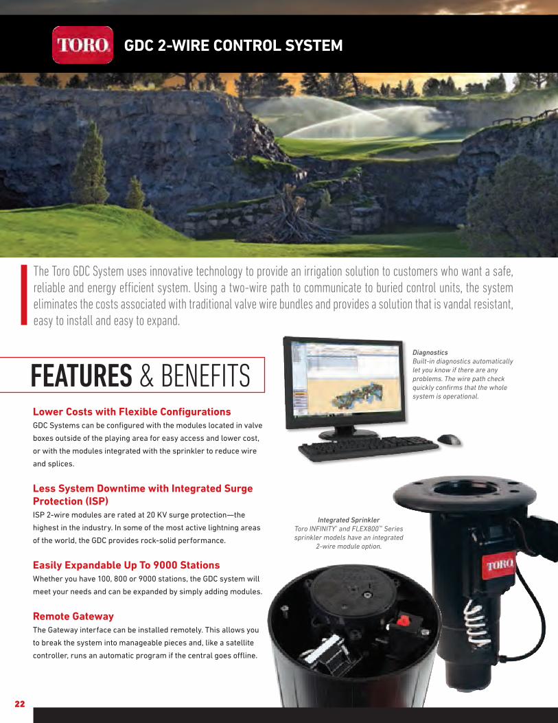
The Toro GDC System uses innovative technology to provide an irrigation solution to customers who want a safe, reliable and energy efficient system. Using a two-wire path to communicate to buried control units, the system eliminates the costs associated with traditional valve wire bundles and provides a solution that is vandal resistant, easy to install and easy to expand.
Lower Costs with Flexible ConfigurationsGDC Systems can be configured with the modules located in valve
boxes outside of the playing area for easy access and lower cost,
or with the modules integrated with the sprinkler to reduce wire
and splices.
Less System Downtime with Integrated Surge Protection (ISP)ISP 2-wire modules are rated at 20 KV surge protection—the
highest in the industry. In some of the most active lightning areas
of the world, the GDC provides rock-solid performance.
Easily Expandable Up To 9000 StationsWhether you have 100, 800 or 9000 stations, the GDC system will
meet your needs and can be expanded by simply adding modules.
Remote GatewayThe Gateway interface can be installed remotely. This allows you
to break the system into manageable pieces and, like a satellite
controller, runs an automatic program if the central goes offline.
GDC 2-WIRE CONTROL SYSTEM
FEATURES & BENEFITSDiagnosticsBuilt-in diagnostics automatically let you know if there are any problems. The wire path check quickly confirms that the whole system is operational.
Integrated SprinklerToro INFINITY® and FLEX800™ Series sprinkler models have an integrated
2-wire module option.

23
SPECIFICATIONSOperational Lynx® Central: - Mapping capabilities - Remote hand-held operation - Weather station integration - Pump station integration• Enhanced diagnostics: - Communication - Electrical shorts/opens - Solenoid check
Installation• Maximum number of wire paths: - 4 per gateway• Maximum number of gateways: - 4 per system (Standard) - 9 per system (Remote)• Maximum number of decoders
per wire path: - 250• Maximum stations per gateway: - 1000 integrated - 1600 off fairway - 1000 remote• Maximum stations per system: - 4000 integrated - 6400 off fairway - 9000 Remote
Electrical• Input power: - 88-264 V ac, 50/60 Hz• Output Power: - Output voltage: 40 V ac max - Output power: 75 VA max - Class 2, SELV• ISP 2-wire modules are rated at 20 KV surge protection• 2-Wire modules wiring: 14 awg
• Simultaneous stations per output board:
- 100• Maximum distance from
central to module (using 14 gauge wire): 2.6 miles• Maximum distance from
module to sprinkler (using 14 gauge wire): 400 ft.• Solenoids per output: 2
DCLS-P• Stations per module: 1, 2 or 4
Temperature• Operating Temperature: 32° F
to 140° F• Storage temperature: -22° F
to 212° F
• No holding power required to operate stations
• Decoder identification is a unique 5-character address
• Standalone option (GDC200)
Off Fairway Configuration
Integrated Configuration
Standard
Lynx®
DEC-ISP-4 DEC-ISP-2 DEC-ISP-1
DEC-PCS-1600
Remote
Lynx® DEC-RS-1000MFIU-2011DR DEC-RS-1000-DR
or
Specifying Information—GatewayDEC-XXX-XXXX
Type Communication Station CountDEC XXX XXXXDEC SA—Stand-alone
PCS—CentralRS—Remote*
200—200 Stations
1600—1600 Stations, Standard
1000-M—1000 Stations, Remote, Wired
1000-DR—1000 Stations, Remote, Radio
*1000-M & 1000-DR only
Specifying Information—2-Wire ModulesDEC-ISP-X
Type ConfigurationDEC-ISP X
DEC-ISP—Module* 1—1-station 2—2-station4—4-station
Example: A 2-station GDC Module would be specified as: DEC-ISP-2
*Refer to sprinkler pages for specifying information on Sprinkler 2-wire Modules

24
SPRINKLERS AND SUBSURFACE DRIP IRRIGATION
Model INF35-6/INF55-6
INF35/INF55
INF34/INF54
FLX35-6/FLX55-6
FLX35/FLX55
FLX34/FLX54
Catalog Pages 26-29 30-33 34-37 38-41 42-45 46-49
Radius 42’-100’ 43’-92’ 52’-99’ 42’-100’ 43’-92’ 52’-99’
Short Radius (mainless) 25’-51’ 25’-50’ 25’-51’ 25’-50’
Radius Reduction Screw X X Optional Optional
Back nozzle Capable X X X X
Inlet Size 1” & 1½” ACME# 1” & 1½” ACME 1” & 1½” ACME 1” & 1½” ACME 1” & 1½” ACME 1” & 1½” ACME
Turf X X X X X X
High Wind X X X X X X
GDC 2-wire Systems X X X X X X
Normally OpenHydraulic System X' X' X'
Spike Guard™ Solenoid X X X X X X
Full Circle X X X X X X
Part-circle Adjustable X X X X
Part/Full Circle In One 40˚-330˚ & 360˚
40˚-330˚ & 360˚
40˚-330˚ & 360˚
40˚-330˚ & 360˚
Ratcheting Riser X X X X
Check Valve X X X
Effluent Water Option X X X X X X
Trajectory Adjustment 7˚-30˚ 25˚ & 15˚ 25˚ & 15˚ 7˚-30˚ 25˚ & 15˚ 25˚ & 15˚
Nozzle Base Clutching X X X X
SMART ACCESS®
Compartment X X X
SMART ACCESS® Cover X X X
Removable Marker X X X
Pilot Valve ServiceableUnder Pressure X X X
Warranty 3 Years/5 Years*
3 Years/5 Years*
3 Years/5 Years*
3 Years/5 Years*
3 Years/5 Years*
3 Years/5 Years*
*When purchased and installed with Toro Swing Joints.X'–Complete sprinkler requires the purchase and assembly of riserless bodies and conversions.
# NPT and BSP models available as riserless bodies only.

25
Model FLEX800 B SERIES T7 Rotor 690 590GF
Catalog Pages 50-53 60-61 62-63 64-65
Radius 25’-95’ Low-flow: 38’–53’High-flow: 46’–83’ 87’-108’ 2'-26
Short Radius (mainless) X X X
Radius Reduction Screw Optional X X
Back nozzle Capable X
Inlet Size 1” NPT, BSP, ACME 1” ACME 1½” NPT 1/2” NPT
Flow Range 7.1-56.3 Gpm Low-flow: 1.7–12.7 GpmHigh-flow: 6.8–30.5 Gpm 51.0-82.2 Gpm .05-4.5 Gpm
Recommended Operating Pressure 50-100 Psi 40-100 Psi 80-100 Psi 20-50 Psi
Turf X X X X
High Wind X X
Low Pressure X X
Normally OpenHydraulic System X
Full Circle X X 1 and 2 Speed X
Part-circle Adjustable X X X
Part-circle Fixed 90˚ and 180˚ X
Part/Full Circle In One 40˚-330˚ & 360˚ X X
Ratcheting Riser FLX35-6B/FLX35B X
Check Valve X X X X
Effluent Water Option X X X
Trajectory Adjustment 7˚-30˚/25˚ & 15˚
Warranty 3 Years/5 Years* 5 Years 3 Years/5 Years* 3 Years
*When purchased and installed with Toro Swing Joints.

26
With the industry’s largest selection of high performance nozzles and TruJectory™ adjustment the INFINTY 35-6/55-6 Series with SMART ACCESS® allows you to put water precisely where you want it for maximum distribution uniformity. And the part/full circle drive and ratcheting riser allows you to simply and economically adjust the area of coverage to match your seasonal watering needs or meet water rationing mandates in seconds with no disassembly or additional parts required.
Industry's Largest Nozzle SelectionNozzles from 42’ to 100’ radius plus a wide assortment of back
nozzles lets you put the precise amount of water exactly where
you need it. All color coded and debris tolerant nozzles threaded
in from the front.
Hot Spot WateringNozzle base can be turned in either direction and held to put down
as much water as needed, precisely where you want it. Standard
on all Toro Part circle Golf rotors!
Adjustment With No DisassemblyA Toro original, simply pull up the riser and ratchet it to the
precise position you want to water.
True Part and Full-Circle in One(40° - 330° part circle)These sprinklers can be full circle today and part circle tomorrow
allowing you to simply and economically adjust the area of
coverage to match your seasonal needs or meet water rationing
mandates.
INFINITY® 35-6/55-6 SERIES GOLF ROTORS
FEATURES & BENEFITS
Smart Access®
Provides top accessibility to all critical components.
No digging or unsightly turf repair scars
No buried wire splices or ground faults
Pilot valve removable with water “ON”
Lower long term cost of ownership
Customizable marker
Replaceable cover if damaged
Increased labor efficiency

INF35-6 CONVERSION UPGRADES
MODELS DESCRIPTION
• INF35-6-3134
• INF35-6-3537
• INF35-6-3134E
• INF35-6-3537E
INF35-6 w/31–34 Nozzles(33 Nozzle Installed)INF35-6 w/35–37 Nozzles(35 Nozzle Installed)INF35-6 w/31–34 Nozzles(33 Nozzle Installed), EffluentINF35-6 w/35–37 Nozzles(35 Nozzle Installed), Effluent
INF55-6 CONVERSION UPGRADES
MODELS DESCRIPTION
• INF55-6-5154
• INF55-6-5558
• INF55-6-59• INF55-6-5154E
• INF55-6-5558E
• INF55-6-59E
INF55-6 w/51–54 Nozzles(53 Nozzle Installed)INF55-6 w/55–58 Nozzles(55 Nozzle Installed)INF55-6 w/59 Nozzle installedINF55-6 w/51–54 Nozzles(53 Nozzle Installed), EffluentINF55-6 w/55–58 Nozzles(55 Nozzle Installed), EffluentINF55-6 w/59 Nozzle installed Effluent
SPECIFICATIONS Operational• Inlet: - INF35-6: 1” ACME - INF55-6: 1½” ACME• Radius: - INF35-6: 42’ – 92’ - INF55-6: 52’ – 100’• Flow Rate: - INF35-6: 7.1 – 45.3 Gpm - INF55-6: 13.9 - 61.1 Gpm• Precipitation Rates: - INF35-6: Minimum - .37”/hr; Maximum - .53”/hr - INF55-6: Minimum - .43”/hr; Maximum - .60”/hr• Pilot Valve: Selectable at 50, 65, 80 and 100 Psi• Recommended Operating Pressure Range: 65-100 psi (maximum -150 Psi and minimum - 40 Psi)• Activation types – Electric Valve-in-Head: - Standard Solenoid: n 24 VAC, 50/60 Hz n Inrush: 0.30 A n Holding 0.20 A - Spike Guard Solenoid: n 24 VAC, 50/60 Hz n Inrush: 0.12 A n Holding 0.10 A - Nickel-Plated Spike Guard Solenoid: n 24 VAC, 50/60 Hz n Inrush: 0.12 A n Holding 0.10 A - DC Latching Solenoid (DCLS): n Momentary low voltage pulse - Integrated GDC Module w/DCLS: n Momentary low voltage pulse• Trajectory: 24 positions from 7° - 30° in 1° increments
Additional Features• INF35-6 has eight nozzle variations (30, 31, 32, 33, 34, 35, 36 and 37)• INF55-6 has nine nozzle variations (51, 52, 53, 54, 55, 56, 57, 58 and 59) • Four in-line nozzles, rotating stream pattern• One back nozzle position• Stator variations: INF35-6 – 3 and INF55-6 – 3• Ratcheting riser• Nozzle base clutching
Warranty• Three years• Five years when installed with Toro Swing Joints
27
Trajectory – 24 PositionsFrom 7° - 30° in 1° increments put water where you want it. Adjust from the top of the sprinkler in seconds, wet or dry. This flexibility lets you tackle every obstacle on the course; wind, trees, bunkers, mounds and more.
7°
30°
Dimensions• SMART ACCESS® Cover and Compartment Diameter: - INF35-6: 75/8” - INF55-6: 75/8” • Body height: - INF35-6: 10” - INF55-6: 113/8” • Weight: - INF35-6: 4.31 lbs. - INF55-6: 5.13 lbs. • Pop-up height to nozzle: 3¼”
Specifying Information—INFINITY 35-6 & INFINITY 55-6INFX5-XXX-X6-7
BodyInlet Arc Nozzle Pressure
Regulation* Activation Type Trajectory Optional
INFX 5 X X X X 6 73—1" 5—11⁄2"
5—Part-circle and Full-circle In One
INF35—30, 31, 32, 33, 34, 35, 36, 37INF55—51, 52, 53, 54, 55, 56, 57, 58, 59
6—65 Psi8—80 Psi1—100 Psi
1—Standard Solenoid2—Spike Guard™ Solenoid3—Nickel-plated Spike Guard Solenoid4—DC Latching Solenoid (DCLS)5—Integrated GDC Module w/DCLS
6—24-position TruJectory
7—Effluent
Example: When specifying an INF35-6 Series Sprinkler with #34 nozzle, pressure regulation at 65 Psi and Spike Guard you would specify: INF35-346-26
Note: Not all models available. * All sprinklers are equipped with the selectable pilot valve that allows settings at 50, 65, 80 and 100 psi.

INFINITY® 35-6/55-6 SERIES GOLF ROTORS
28 | Learn more at www.toro.com/golf
Nozzle/psi/gpm #34 Nozzle @ 65 psi, 30.0 gpm #35 Nozzle @ 65 psi, 32.4 gpm #36 Nozzle @ 80 psi, 34.0 gpm
Trajectory 7° 10° 15° 20° 25° 30° 7° 10° 15° 20° 25° 30° 7° 10° 15° 20° 25° 30°
"A" Radius 58' 60' 63' 67' 74' 70' 59' 61' 64' 70' 76' 74' 64' 68' 76' 80' 84' 82'
"B" Spray Height 4' 4' 6' 11' 14' 17' 4' 5' 7' 11' 15' 17' 5' 7' 9' 14' 17' 22'
"C" Distance from Head 24' 26' 35' 39' 39' 39' 30' 32' 36' 43' 43' 43' 25' 38' 40' 45' 49' 45'
Nozzle/psi/gpm #37 Nozzle @ 80 psi, 39.8 gpm
Trajectory 7° 10° 15° 20° 25° 30°
"A" Radius 65' 69' 78' 82' 86' 84'
"B" Spray Height 5' 7' 9' 14' 18' 22'
"C" Distance from Head 30' 39' 41' 46' 50' 46'
Nozzle/psi/gpm #54 Nozzle @ 65 psi, 31.2 gpm #55 Nozzle @ 65 psi, 33.8 gpm #56 Nozzle @ 80 psi, 35.7 gpm
Trajectory 7° 10° 15° 20° 25° 30° 7° 10° 15° 20° 25° 30° 7° 10° 15° 20° 25° 30°
"A" Radius 58' 60' 63' 67' 74' 70' 59' 62' 66' 70' 76' 77' 72' 73' 75' 82' 85' 82'
"B" Spray Height 5' 6' 8' 10' 15' 17' 6' 6' 9' 11' 15' 17' 5' 7' 9' 14' 17' 22'
"C" Distance from Head 31' 34' 40' 41' 41' 42' 34' 36' 43' 45' 45' 45' 25' 38' 40' 45' 49' 45'
Nozzle/psi/gpm #57 Nozzle @ 80 psi, 41.9 gpm #58 Nozzle @ 80 psi, 46.2 gpm #59 Nozzle @ 80 psi, 53.3 gpm
Trajectory 7° 10° 15° 20° 25° 30° 7° 10° 15° 20° 25° 30° 7° 10° 15° 20° 25° 30°
"A" Radius 72' 74' 77' 83' 89' 85' 75' 77' 83' 87' 92' 88' 77' 78' 84' 89' 96' 92'
"B" Spray Height 5' 7' 9' 14' 18' 22' 6' 7' 10' 15' 18' 22' 7' 8' 11' 16' 21' 25'
"C" Distance from Head 30' 39' 41' 46' 50' 46' 38' 40' 43' 47' 52' 48' 42' 44' 45' 47' 53' 49'
Information is for reference only. Actual results may vary.
INFINITY 35-6 TRAJECTORY PERFORMANCE
Nozzle/psi/gpm #31 Nozzle @ 65 psi, 15.5 gpm #32 Nozzle @ 65 psi, 20.5 gpm #33 Nozzle @ 65 psi, 22.9 gpm
Trajectory 7° 10° 15° 20° 25° 30° 7° 10° 15° 20° 25° 30° 7° 10° 15° 20° 25° 30°
"A" Radius 46' 46' 50' 53' 54' 50' 46' 49' 51' 55' 63' 54' 54' 56' 59' 62' 66' 61'
"B" Spray Height 4' 4' 5' 8' 11' 13' 3' 4' 6' 9' 12' 15' 4' 5' 7' 9' 13' 15'
"C" Distance from Head 25' 25' 26' 33' 33' 33' 20' 24' 28' 34' 34' 34' 23' 28' 32' 34' 35' 35'
INFINITY 55-6 TRAJECTORY PERFORMANCE
Nozzle/psi/gpm #51 Nozzle @65 psi, 15.7 gpm #52 Nozzle @65 psi, 20.8 gpm #53 Nozzle @65 psi, 23.4 gpm
Trajectory 7° 10° 15° 20° 25° 30° 7° 10° 15° 20° 25° 30° 7° 10° 15° 20° 25° 30°
"A" Radius 46' 46' 51' 53' 54' 50' 49' 50' 51' 55' 64' 65' 54' 56' 59' 62' 68' 61'
"B" Spray Height 4' 4' 6' 10' 13' 15' 4' 4' 6' 9' 11' 13' 5' 6' 7' 9' 13' 15'
"C" Distance from Head 26' 27' 32' 38' 40' 41' 22' 26' 31' 35' 34' 30' 30' 33' 32' 35' 37' 37'
AC
B

Learn more at www.toro.com/golf | 29
INFINITY 35-6 SERIES PERFORMANCE CHART
Base Pressure
Nozzle Set 30
(White)
Nozzle Set 31
(Yellow)
Nozzle Set 32
(Blue)
Nozzle Set 33
(Brown)
Nozzle Set 34
(Orange)
Nozzle Set 35
(Green)
Nozzle Set 36
(Gray)
Nozzle Set 37
(Black)
102-2208 102-4587 102-4588 102-4589 102-0728 102-0729 102-0730 102-4261
Blue Gray Blue Gray Red Gray Orange Gray Orange Gray Blue Gray Blue Gray Orange Gray
102-2925 102-2910 102-2925 102-2910 102-2928 102-2910 102-2926 102-2910 102-2926 102-2910 102-2925 102-2910 102-2925 102-2910 102-2926 102-2910
psi Radius gpm Radius gpm Radius gpm Radius gpm Radius gpm Radius gpm Radius gpm Radius gpm50 42 7.1 52 13.7 61 17.1 64 20.2 69 27.4 — — — — — —65 45 8.7 54 15.5 63 20.5 66 22.9 74 30.0 76 32.4 80 34.0 — —80 46 9.6 57 17.0 67 22.6 70 25.3 77 33.2 79 35.8 84 37.5 86 40.8
100 48 11.2 59 18.9 72 25.2 74 28.2 80 37.0 84 39.9 88 42.5 92 45.3Stator 102-6929 Blue 102-1939 Yellow 102-1940 White
Conversions INF35-6-3134 INF35-6-3537
INFINITY 55-6 SERIES PERFORMANCE CHART
BasePressure
Nozzle Set 51
(Yellow)
Nozzle Set 52
(Blue)
Nozzle Set 53
(Brown)
Nozzle Set 54
(Orange)
Nozzle Set 55
(Green)
Nozzle Set 56
(Gray)
Nozzle Set 57
(Black)
Nozzle Set 58
(Red)
Nozzle Set 59
(Beige)
102-4587 102-4588 102-4589 102-0728 102-0729 102-0730 102-4261 102-4260 102-4259
Blue Gray Red Gray Orange Gray Orange Gray Blue Gray Blue Gray Orange Gray Blue Gray Blue Gray
102-2925 102-2910 102-2928 102-2910 102-2926 102-2910 102-2926 102-2910 102-2925 102-2910 102-2925 102-2910 102-2926 102-2910 102-2925 102-2910 102-2925 102-2910
psi Radius gpm Radius gpm Radius gpm Radius gpm Radius gpm Radius gpm Radius gpm Radius gpm Radius gpm50 52 13.9 62 17.4 66 20.7 69 28.6 — — — — — — — — — —65 54 15.7 64 20.8 68 23.4 74 31.2 76 33.8 81 35.7 — — — — — —80 57 17.2 68 22.9 72 25.8 77 34.4 79 37.2 85 39.4 89 43.6 92 47.5 96 57.0
100 59 19.1 73 25.5 76 28.7 80 38.2 84 41.3 89 43.7 94 48.5 95 51.1 100 61.1Stator 102-1939 Yellow 102-1940 White 102-1941
Conver. INF55-6-5154 INF55-6-5558 INF55-6-59■ Not recommended at these pressures. Radius shown in feet.
Toro recommends the use of a 11⁄4" swing joint at flows over 25-Gpm (95-LPM). Sprinkler radius data collected in Toro’s zero wind test facility per ASAE standard S398.1.Actual site conditions must be considered when selecting the appropriate nozzle.
All sprinklers are equipped with the selectable pilot valve that allows settings at 50, 65, 80 and 100 psi.
Note: Main Nozzle Adapter Data Located on Pages 54. Back Nozzle Data Located on Page 59.
Main Nozzle AdapterA wide assortment of intermediate and inner nozzles for use in the main nozzle adapter and back nozzle position provide unmatched nozzle flexibility.
INFINITY® 35-6/55-6 SERIES GOLF ROTORS

30
The New INFINITY 35/55 Series with SMART ACCESS® features a dual trajectory main nozzle that provides exceptional nozzle performance at the 25° standard angle position and great performance in windy applications at the 15° low angle position. And the part/full circle drive and ratcheting riser allows you to adjust the area of coverage to match your seasonal watering needs or meet water rationing mandates in seconds with no additional parts required.
Industry's Largest Nozzle SelectionNozzles from 43’ to 92’ radius plus a wide assortment of back
nozzles lets you put the precise amount of water exactly where
you need it. All nozzles threaded in from front.
Stainless Steel Valve SeatEliminates body damage from rocks and debris. This in-
destructible stainless steel seat is molded to the body and
virtually eliminates body replacements due to seat damage.
Standard on all Toro Golf rotors!
Radius Reduction ScrewAllows for fine tuning the radius to exactly the distance you need.
In combination with main nozzle sizing and trajectory adjustment
the radius reduction screw can effectively reduce the sprinkler
throw down to 30’.
True Part and Full-Circle in One(40° - 330° part circle)These sprinklers can be full circle today and part circle tomorrow
allowing you to adjust the area of coverage to match your
seasonal needs or meet water rationing mandates.
INFINITY® 35/55 SERIES GOLF ROTORS
FEATURES & BENEFITS
Smart Access®
Provides top accessibility to all critical components.
No digging or unsightly turf repair scars
No buried wire splices or ground faults
Pilot valve removable with water “ON”
Lower long term cost of ownership
Customizable marker
Replaceable cover if damaged
Increased labor efficiency

INF35 CONVERSION UPGRADES
MODELS DESCRIPTION
• INF35-3134
• INF35-3537
• INF35-3134E
• INF35-3537E
INF35 w/31–34 Nozzles (#3 Nozzle Installed)INF35 w/35–37 Nozzles (#5 Nozzle Installed) INF35 w/31–34 Nozzles (#3 Nozzle Installed), Effluent INF35 w/35–37 Nozzles (#5 Nozzle Installed), Effluent
INF55 CONVERSION UPGRADES
MODELS DESCRIPTION
• INF55-5154 • INF55-5558 • INF55-59 • INF55-5154E • INF55-5558E
• INF55-59E
INF55 w/51–54 Nozzles (#3 Nozzle Installed)INF55 w/55–58 Nozzles (#5 Nozzle Installed) INF55 w/59 NozzleINF55 w/51–54 Nozzles (#3 Nozzle Installed), EffluentINF55 w/55–58 Nozzles (#5 Nozzle Installed), EffluentINF55 w/59 Nozzle, Effluent
SPECIFICATIONS Operational• Inlet: - INF35: 1” ACME - INF55: 1½” ACME• Radius: - INF35: 43’ – 83’ - INF55: 55’ – 92’• Flow Rate: - INF35: 8.2 – 47.3 gpm - INF55: 14.1 – 61.3 gpm• Precipitation Rates: - INF35: Minimum - .41”/hr; Maximum - .45”/hr - INF55: Minimum - .46”/hr; Maximum - .58”/hr• Pilot Valve: Selectable at 50, 65, 80 and 100 psi• Recommended Operating Pressure Range: 65-100 psi (maximum – 150 Psi and minimum – 40 psi)• Activation types – Electric Valve-in-Head: - Standard Solenoid: n 24 VAC, 50/60 Hz n Inrush: 0.30 A n Holding 0.20 A - Spike Guard Solenoid: n 24 VAC, 50/60 Hz n Inrush: 0.12 A n Holding 0.10 A - Nickel-Plated Spike Guard Solenoid: n 24 VAC, 50/60 Hz n Inrush: 0.12 A n Holding 0.10 A - DC Latching Solenoid (DCLS): n Momentary low voltage pulse - Integrated GDC Module w/DCLS: n Momentary low voltage pulse
Additional Features• INF35 has eight nozzle variations (30, 31, 32, 33, 34, 35, 36 & 37)• INF55 has nine nozzle variations (51, 52, 53, 54, 55, 56, 57, 58 & 59)• Three in-line nozzles, rotating stream pattern• Two back nozzle positions• Stator variations: 3• Radius reduction screw 363-4839 for fine tuning• Ratcheting riser• Nozzle base clutching
Warranty• Three years• Five years when installed with Toro Swing Joints
31
Dimensions• SMART ACCESS® Cover and Compartment Diameter: - INF35: 75/8” - INF55: 75/8”• Body height: - INF35: 10” - INF55: 113/8”• Weight: - INF35: 4.26 lbs. - INF55: 5.08 lbs.• Pop-up height to nozzle: 3¼”
Dual TrajectoryThe 25° setting provides maximum distance of throw and the 15° setting provides improved wind performance, radius reduction and obstacle avoidance.
15°
25°
OR
Specifying Information—INFINITY 35 & INFINITY 55INFX5-XXX-X7
BodyInlet
Arc NozzlePressure
Regulation*Activation Type Optional
INFX 5 X X X X 73—1" 5—11⁄2"
5—Part-circle and Full-circle In One
INF35—30, 31, 32, 33, 34, 35, 36, 37INF55—51, 52, 53, 54, 55, 56, 57, 58, 59
6—65 Psi8—80 Psi1—100 Psi
1—Standard Solenoid2—Spike Guard™ Solenoid3—Nickel-plated Spike Guard Solenoid4—DC Latching Solenoid (DCLS)5—Integrated GDC Module w/DCLS
7—Effluent
Example: When specifying an INF35 Series Sprinkler with #34 nozzle, pressure regulation at 65 Psi and Spike Guard you would specify: INF35–346–2
Note: Not all models available. * All sprinklers are equipped with the selectable pilot valve that allows settings at 50, 65, 80 and 100 psi.

32 | Learn more at www.toro.com/golf
INFINITY 35 SERIES PERFORMANCE CHART—25°
FrontNozzle
Positions
Nozzle Set 30
(White Plug)
Nozzle Set 31
(Yellow)
Nozzle Set 32
(Blue)
Nozzle Set 33
(Brown)
Nozzle Set 34
(Orange)
Nozzle Set 35
(Green)
Nozzle Set 36
(Gray)
Nozzle Set 37
(Black)
102-2208 102-6906 102-0726 102-6907 102-0728 102-6955 102-6935 102-6936
Yellow Biege Yellow Brown Yellow Yellow Yellow Yellow Yellow Yellow Yellow Green Green Green Green Green
102-5670 102-6942 102-5670 102-5671 102-5670 102-6884 102-5670 102-6884 102-5670 102-6884 102-5670 102-6885 102-6531 102-6885 102-6531 102-6885
BackNozzle
PositionsRed Plug Red Plug Red Plug Red Plug Red Plug Red Plug Red Plug Red Plug Red Plug Red Plug Red Plug Red Plug Red Plug Red Plug Red Plug Red Plug
102-4335 102-4335 102-4335 102-4335 102-4335 102-4335 102-4335 102-4335 102-4335 102-4335 102-4335 102-4335 102-4335 102-4335 102-4335 102-4335
psi Radius gpm Radius gpm Radius gpm Radius gpm Radius gpm Radius gpm Radius gpm Radius gpm
50 43 8.2 53 13.8 56 18.3 61 21.7 65 25.3 — — — — — —65 45 10.0 53 15.5 59 20.5 64 24.4 68 28.2 72 34.1 — — — —80 46 11.5 57 17.3 62 22.7 67 27.1 71 31.1 75 37.8 78 40.3 80 44.0
100 47 13.4 59 19.1 65 24.9 70 29.8 74 34.1 79 40.9 81 43.8 83 47.3
INFINITY 35 NOZZLE APEX
Pressure Nozzle Apex at 15˚ Apex at 25°
65 psi
31 6’ @ 51’ 13’ @ 54’
32 6’ @ 51’ 11’ @ 64’
33 7’ @ 59’ 13’ @ 68’
34 8’ @ 63’ 15’ @ 74’
35 9’ @ 66’ 15’ @ 76’
80 psi36 8’ @ 75’ 18’ @ 83’
37 9’ @ 74’ 19’ @ 82’
INFINITY® 35/55 SERIES GOLF ROTORS
INFINITY 35 SERIES PERFORMANCE CHART—15°psi Radius gpm Radius gpm Radius gpm Radius gpm Radius gpm Radius gpm Radius gpm Radius gpm50 43 8.2 52 13.6 58 18.1 61 21.5 62 25.6 — — — — — —65 45 10.0 54 15.3 60 20.3 64 24.2 65 27.3 69 33.1 — — — —80 46 11.5 58 17.2 64 22.6 69 26.8 69 30.2 75 36.8 76 39.7 76 42.9
100 47 13.4 60 19.0 66 24.7 71 29.5 72 32.9 78 39.5 82 42.6 82 46.1Stator 102-6929 Blue 102-1939 Yellow 102-1940 White
Conversions INF35-3134 INF35-3537
■ Not recommended at these pressures. Radius shown in feet. Toro recommends the use of a 11⁄4" swing joint at flows over 25-Gpm (95-LPM). Sprinkler radius data collected in Toro’s zero wind test facility per ASAE standard S398.1.
Actual site conditions must be considered when selecting the appropriate nozzle.All sprinklers are equipped with the selectable pilot valve that allows settings at 50, 65, 80 and 100 psi.

Learn more at www.toro.com/golf | 33
Note: Main Nozzle Adapter Data Located on Pages 54. Back Nozzle Data Located on Page 59.
INFINITY 55 SERIES PERFORMANCE CHART—25°
FrontNozzle
Positions
Nozzle Set 51
(Yellow)
Nozzle Set 52
(Blue)
Nozzle Set 53
(Brown)
Nozzle Set 54
(Orange)
Nozzle Set 55
(Green)
Nozzle Set 56
(Gray)
Nozzle Set 57
(Black)
Nozzle Set 58
(Red)
Nozzle Set 59
(Beige)
102-6906 102-0726 102-6907 102-0728 102-6955 102-6935 102-6936 102-6909 102-4259
Yellow Brown Yellow Yellow Yellow Yellow Yellow Yellow Yellow Green Green Green Green Green Green Green Green Green
102-5670 102-5671 102-5670 102-6884 102-5670 102-6884 102-5670 102-6884 102-5670 102-6885 102-6531 102-6885 102-6531 102-6885 102-6531 102-6885 102-6531 102-6885
BackNozzle
PositionsRed Plug Red Plug Red Plug Red Plug Red Plug Red Plug Red Plug Red Plug Red Plug Red Plug Red Plug Red Plug Red Plug Red Plug Red Plug Red Plug Red Plug Red Plug
102-4335 102-4335 102-4335 102-4335 102-4335 102-4335 102-4335 102-4335 102-4335 102-4335 102-4335 102-4335 102-4335 102-4335 102-4335 102-4335 102-4335 102-4335
psi Radius gpm Radius gpm Radius gpm Radius gpm Radius gpm Radius gpm Radius gpm Radius gpm Radius gpm
50 55 14.1 57 18.5 62 22.3 66 25.8 — — — — — — — — — —65 57 15.8 60 20.9 65 25.1 69 28.7 73 35.9 — — — — — — — —80 59 17.5 61 23.1 68 27.8 72 31.7 76 39.7 80 43.1 83 48.2 85 50.0 89 57.5
100 61 19.3 63 25.3 71 30.3 75 34.5 80 43.5 83 49.0 88 51.5 90 53.9 92 61.3
INFINITY 55 NOZZLE APEX
Pressure Nozzle Apex at 15˚ Apex at 25°
65 psi
51 6’ @ 51’ 13’ @ 54’
52 6’ @ 51’ 11’ @ 64’
53 7’ @ 59’ 13’ @ 68’
54 8’ @ 63’ 15’ @ 74’
55 9’ @ 66’ 15’ @ 76’
80 psi
56 8’ @ 75’ 18’ @ 83’
57 9’ @ 74’ 19’ @ 82’
58 10’ @ 82’ 18’ @ 87’
59 11’ @ 81’ 21’ @ 91’
INFINITY® 35/55 SERIES GOLF ROTORS
INFINITY 55 SERIES PERFORMANCE CHART—15°psi Radius gpm Radius gpm Radius gpm Radius gpm Radius gpm gadius gpm Radius gpm Radius gpm Radius gpm50 55 14.0 59 16.5 62 22.2 63 25.6 — — — — — — — — — —65 56 15.6 62 20.7 65 25.0 66 28.5 75 35.3 — — — — — — — —80 59 17.4 66 23.0 69 27.7 70 31.5 78 39.0 78 42.4 79 46.9 79 49.5 82 57.2
100 60 19.2 68 25.1 71 30.2 72 34.3 80 41.9 81 47.2 83 52.1 83 53.4 85 60.8Stator 102-1939 Yellow 102-1940 White 102-1941 White
Conver-sions
INF35-3134 INF35-3537 INF55-59
■ Not recommended at these pressures. Radius shown in feet. Toro recommends the use of a 11⁄4" swing joint at flows over 25-Gpm (95-LPM). Sprinkler radius data collected in Toro’s zero wind test facility per ASAE standard S398.1.
Actual site conditions must be considered when selecting the appropriate nozzle.All sprinklers are equipped with the selectable pilot valve that allows settings at 50, 65, 80 and 100 psi.

34
The New INFINITY 34/54 is Toro’s Premium full-circle golf sprinkler series with SMART ACCESS®. The dual trajectory main nozzle provides exceptional nozzle performance at the 25° standard angle position and great performance in windy applications at the 15° low angle position. And the consistency of the constant velocity full circle drive ensures even water application across the coverage area every time you water.
Industry's Largest Nozzle SelectionNozzles from 52’ to 100’. Color coded for easy flow and radius
identification and threaded from the front to simplify servicing.
Constant Velocity Full Circle DriveEnsures consistent rotation speeds when matched with station
run times for even water application across the coverage area
every time you water.
Radius Reduction Screw for Fine TuningIn combination with main nozzle sizing and trajectory
adjustment the radius reduction screw can effectively
reduce the sprinkler throw down to 30’.
INFINITY® 34/54 SERIES GOLF ROTORS
FEATURES & BENEFITS
Smart Access®
Provides top accessibility to all critical components.Five Activation Types
No digging or unsightly turf repair scars
No buried wire splices or ground faults
Pilot valve removable with water “ON”
Lower long term cost of ownership
Customizable marker
Replaceable cover if damaged
Increased labor efficiency
Standard solenoid
Spike Guard™ solenoid
Nickel plated Spike Guard solenoid
DC Latching Solenoid (DCLS)
Integrated GDC module with DCLS
Available on all INFINITY models!

INF34 CONVERSION UPGRADES
MODELS DESCRIPTION
• INF34-3134
• INF34-3537
• INF34-3134E
• INF34-3537
INF34 w/31–34 Nozzles (33 Nozzle Installed)INF34 w/35–37 Nozzles (35 Nozzle Installed)INF34 w/31–34 Nozzles (33 Nozzle Installed), Effluent INF34 w/35–37 Nozzles (35 Nozzle Installed), Effluent
INF54 CONVERSION UPGRADES
MODELS DESCRIPTION
• INF54-5154
• INF54-5558
• INF54-59 • INF54-5154E
• INF54-5558E
• INF54-59E
INF54 w/51–54 Nozzles (53 Nozzle Installed)INF54 w/55–58 Nozzles (55 Nozzle Installed) INF54 w/ 59 Nozzle installedINF54 w/51–54 Nozzles (53 Nozzle Installed), EffluentINF54 w/55–58 Nozzles (55 Nozzle Installed), EffluentINF54 w/ 59 Nozzle installed Effluent
SPECIFICATIONS Features• Dual Trajectory adjustment on main nozzle - 25° or 15°• Constant velocity full circle drive• Radius reduction screw can effectively reduce the sprinkler throw down
to 30’
Operational• Inlet: - INF34: 1” ACME - INF54: 1½” ACME• Radius: - INF34: 52’ – 91’ - INF54: 52’ – 99’• Flow Rate: - INF34: 13.0 – 46.9 gpm - INF54: 13.2 - 61.8 gpm• Precipitation Rates: - INF34: Minimum - .33”/hr; Maximum - .55”/hr - INF54: Minimum - .33”/hr; Maximum - .61”/hr• Pilot Valve: Selectable at 50, 65, 80 and 100 psi• Recommended Operating Pressure Range: 65-100 psi (maximum-150 psi
and minimum-40 psi)• Activation types – Electric Valve-in-Head: - Standard Solenoid: n 24 VAC, 50/60 Hz n Inrush: 0.30 A n Holding 0.20 A - Spike Guard Solenoid: n 24 VAC, 50/60 Hz n Inrush: 0.12 A n Holding 0.10 A - Nickel-Plated Spike Guard Solenoid: n 24 VAC, 50/60 Hz n Inrush: 0.12 A n Holding 0.10 A - DC Latching Solenoid (DCLS): n Momentary low voltage pulse - Integrated GDC Module w/DCLS: n Momentary low voltage pulse• Trajectory: 25° or 15°
Dimensions• SMART ACCESS® Cover and Compartment Diameter: - INF34: 75/8” - INF54: 75/8” • Body height: - INF34: 10” - INF54: 113/8” • Weight: - INF34: 4.22 lbs. - INF54: 5.04 lbs. • Pop-up height to nozzle: 3¼”
35
Warranty• Three years• Five years when installed with
Toro Swing Joints
Dual Trajectory - 25° or 15°Provides two selections for the main nozzle trajectory; the 25 degree setting provides maximum distance of throw and the 15 degree setting provides improved wind performance, radius reduction and obstacle avoidance.
Specifying Information—INFINITY 34 & INFINITY 54INFX4-XXX-X-7
BodyInlet
Arc NozzlePressure
Regulation*Activation Type Optional
INFX 5 X X X X 73—1" 5—11⁄2"
4—Full Circle INF34—31, 32, 33, 34, 35, 36, 37INF54—51, 52, 53, 54, 55, 56, 57, 58, 59
6—65 Psi8—80 Psi1—100 Psi
1—Standard Solenoid2—Spike Guard™ Solenoid3—Nickel-plated Spike Guard Solenoid4—DC Latching Solenoid (DCLS)5—Integrated GDC Module w/DCLS
7—Effluent
Example: When specifying an INF34 Series Sprinkler with #34 nozzle, pressure regulation at 65 Psi and Spike Guard you would specify: INF34–346–2
Note: Not all models available. * All sprinklers are equipped with the selectable pilot valve that allows settings at 50, 65, 80 and 100 psi.
15°
25°

INFINITY® 34/54 SERIES GOLF ROTORS
36 | Learn more at www.toro.com/golf
INFINITY 34 NOZZLE APEX
Pressure Nozzle Apex at 15˚ Apex at 25°
65 psi
31 6’ @ 51’ 13’ @ 54’
32 6’ @ 51’ 11’ @ 64’
33 7’ @ 59’ 13’ @ 68’
34 8’ @ 63’ 15’ @ 74’
35 9’ @ 66’ 15’ @ 76’
80 psi36 8’ @ 75’ 18’ @ 83’
37 9’ @ 74’ 19’ @ 82’
INFINITY 34 SERIES PERFORMANCE CHART—25°
FrontNozzle
Positions
Nozzle Set 31
(Yellow)
Nozzle Set 32
(Blue)
Nozzle Set 33
(Brown)
Nozzle Set 34
(Orange)
Nozzle Set 35
(Green)
Nozzle Set 36
(Gray)
Nozzle Set 37
(Black)
102-0725 102-7001 102-0727 102-7002 102-6908 102-0730 102-4261
Red Plug Red Plug Red Plug Red Plug Red Plug Red Plug Red Plug Red Plug Red Plug Red Plug Red Plug Red Plug Red Plug Brown
102-4335 102-4335 102-4335 102-4335 102-4335 102-4335 102-4335 102-4335 102-4335 102-4335 102-4335 102-4335 102-4335 102-6883
BackNozzle
PositionsYellow Blue Yellow Orange Yellow Red Yellow Beige Yellow Beige Yellow Red Yellow Gray
102-6937 102-2925 102-6937 102-2926 102-6937 102-2928 102-6937 102-2929 102-6937 102-2929 102-6937 102-6944 102-6937 102-6945
psi Radius gpm Radius gpm Radius gpm Radius gpm Radius gpm Radius gpm Radius gpm
50 57 13.0 58 15.5 64 21.9 68 24.4 — — — — — —65 58 14.6 60 18.0 68 24.4 72 28.1 76 32.2 — — — —80 60 16.2 63 20.5 72 26.9 76 31.1 80 35.6 83 38.2 85 41.5
100 62 17.9 66 23.4 75 29.8 79 34.9 84 49.3 88 43.4 91 46.9
INFINITY 34 SERIES PERFORMANCE CHART—15°
psi Radius gpm Radius gpm Radius gpm Radius gpm Radius gpm Radius gpm Radius gpm
50 52 12.9 53 15.6 60 21.7 62 25.5 — — — — — —
65 53 14.4 54 17.1 61 24.2 64 28.0 67 32.1 — — — —
80 56 16.0 57 19.0 65 26.6 69 31.0 73 35.5 76 38.0 77 41.3
100 57 17.5 59 20.5 67 29.5 71 33.9 75 38.4 80 43.1 81 46.8
Stator 102-6929 Blue 102-1940 White
Conversions INF34-3134 INF34-3537
■ Not recommended at these pressures. Radius shown in feet. Toro recommends the use of a 11⁄4" swing joint at flows over 25-Gpm (95-LPM). Sprinkler radius data collected in Toro’s zero wind test facility per ASAE standard S398.1.
Actual site conditions must be considered when selecting the appropriate nozzle.All sprinklers are equipped with the selectable pilot valve that allows settings at 50, 65, 80 and 100 psi.
Note: Main Nozzle Adapter Data Located on Pages 54. Back Nozzle Data Located on Page 59.
Learn more at www.toro.com/golf | 37
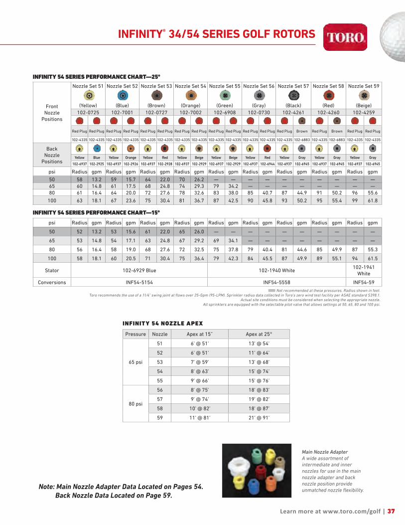
INFINITY 54 SERIES PERFORMANCE CHART—25°
FrontNozzle
Positions
Nozzle Set 51
(Yellow)
Nozzle Set 52
(Blue)
Nozzle Set 53
(Brown)
Nozzle Set 54
(Orange)
Nozzle Set 55
(Green)
Nozzle Set 56
(Gray)
Nozzle Set 57
(Black)
Nozzle Set 58
(Red)
Nozzle Set 59
(Beige)
102-0725 102-7001 102-0727 102-7002 102-6908 102-0730 102-4261 102-4260 102-4259
Red Plug Red Plug Red Plug Red Plug Red Plug Red Plug Red Plug Red Plug Red Plug Red Plug Red Plug Red Plug Red Plug Brown Red Plug Brown Red Plug Red Plug
102-4335 102-4335 102-4335 102-4335 102-4335 102-4335 102-4335 102-4335 102-4335 102-4335 102-4335 102-4335 102-4335 102-6883 102-4335 102-6883 102-4335 102-4335
BackNozzle
PositionsYellow Blue Yellow Orange Yellow Red Yellow Beige Yellow Beige Yellow Red Yellow Gray Yellow Gray Yellow Gray
102-6937 102-2925 102-6937 102-2926 102-6937 102-2928 102-6937 102-2929 102-6937 102-2929 102-6937 102-6944 102-6937 102-6945 102-6937 102-6945 102-6937 102-6945
psi Radius gpm Radius gpm Radius gpm Radius gpm Radius gpm Radius gpm Radius gpm Radius gpm Radius gpm
50 58 13.2 59 15.7 64 22.0 70 26.2 — — — — — — — — — —65 60 14.8 61 17.5 68 24.8 74 29.3 79 34.2 — — — — — — — —80 61 16.4 64 20.0 72 27.6 78 32.6 83 38.0 85 40.7 87 44.9 91 50.2 96 55.6
100 63 18.1 67 23.6 75 30.4 81 36.7 87 42.5 90 45.8 93 50.2 95 55.4 99 61.8
INFINITY 54 SERIES PERFORMANCE CHART—15°
psi Radius gpm Radius gpm Radius gpm Radius gpm Radius gpm Radius gpm Radius gpm Radius gpm Radius gpm
50 52 13.2 53 15.6 61 22.0 65 26.0 — — — — — — — — — —
65 53 14.8 54 17.1 63 24.8 67 29.2 69 34.1 — — — — — — — —
80 56 16.4 58 19.0 68 27.6 72 32.5 75 37.8 79 40.4 81 44.6 85 49.9 87 55.3
100 58 18.1 60 20.5 71 30.4 75 36.4 79 42.3 84 45.5 87 49.9 89 55.1 94 61.5
Stator 102-6929 Blue 102-1940 White102-1941
White
Conversions INF54-5154 INF54-5558 INF54-59
■ Not recommended at these pressures. Radius shown in feet. Toro recommends the use of a 11⁄4" swing joint at flows over 25-Gpm (95-LPM). Sprinkler radius data collected in Toro’s zero wind test facility per ASAE standard S398.1.
Actual site conditions must be considered when selecting the appropriate nozzle.All sprinklers are equipped with the selectable pilot valve that allows settings at 50, 65, 80 and 100 psi.
INFINITY 54 NOZZLE APEX
Pressure Nozzle Apex at 15˚ Apex at 25°
65 psi
51 6’ @ 51’ 13’ @ 54’
52 6’ @ 51’ 11’ @ 64’
53 7’ @ 59’ 13’ @ 68’
54 8’ @ 63’ 15’ @ 74’
55 9’ @ 66’ 15’ @ 76’
80 psi
56 8’ @ 75’ 18’ @ 83’
57 9’ @ 74’ 19’ @ 82’
58 10’ @ 82’ 18’ @ 87’
59 11’ @ 81’ 21’ @ 91’
INFINITY® 34/54 SERIES GOLF ROTORS
Main Nozzle AdapterA wide assortment of intermediate and inner nozzles for use in the main nozzle adapter and back nozzle position provide unmatched nozzle flexibility.

38
With the industry’s largest selection of high performance nozzles and TruJectory™ adjustment the New FLEX800 35-6/55-6 Series allows you to put water precisely where you want it for maximum distribution uniformity. And the part/full circle drive allows you to simply and economically adjust the area of coverage to match your seasonal watering needs or meet water rationing mandates in seconds with no disassembly or additional parts required.
Industry's Largest Nozzle SelectionNozzles from 42’ to 100’ radius plus a wide assortment of back
nozzles lets you put the precise amount of water exactly where
you need it. All nozzles threaded in from the front.
20,000 Volt Lightning RatingSpike-Guard™ solenoid virtually eliminates the need for
replacements in high lightning areas. Draws half the amperage
of traditional solenoids so you can run twice as many sprinklers
simultaneously, reduce the cost of wire during initial installation
or increase the distance from controller to sprinkler.
Adjustment With No DisassemblyToro exclusive, simply pull up the riser and ratchet it to the precise
position you want to water.
True Part and Full-Circle in One (40° - 330° part circle)These sprinklers can be full circle today and part circle tomorrow
allowing you to simply and economically adjust the area of
coverage to match your seasonal needs or meet water rationing
mandates.
FLEX800™ 35-6/55-6 SERIES GOLF ROTORS
FEATURES & BENEFITS
Trajectory – 24 PositionsFrom 7° - 30° in 1° increments put water where you want it. Adjust from the top of the sprinkler in seconds, wet or dry. This flexibility lets you tackle every obstacle on the course; wind, trees, bunkers, mounds and more.
7°
30°
NEW!
FLX35-6 FLX55-6

FLX35-6 CONVERSION UPGRADES
MODELS DESCRIPTION
• FLX35-6-3134
• FLX35-6-3537
• FLX35-6-3134E
• FLX35-6-3537E
FLX35-6 w/31–34 Nozzles(33 Nozzle Installed)FLX35-6 w/35–37 Nozzles(35 Nozzle Installed)FLX35-6 w/31–34 Nozzles(33 Nozzle Installed), EffluentFLX35-6 w/35–37 Nozzles(35 Nozzle Installed), Effluent
FLX55-6 CONVERSION UPGRADES — RIBBED BODY
MODELS DESCRIPTION
• FLX55-6-5154
• FLX55-6-5558
• FLX55-6-59• FLX55-6-5154E
• FLX55-6-5558E
• FLX55-6-59E• 102-5011
• 102-0950
FLX55-6 w/51–54 Nozzles(53 Nozzle Installed)FLX55-6 w/55–58 Nozzles(55 Nozzle Installed)FLX55-6 w/59 Nozzle installedFLX55-6 w/51–54 Nozzles(53 Nozzle Installed), EffluentFLX55-6 w/55–58 Nozzles(55 Nozzle Installed), FLX55-6 w/59 Nozzle installed, Effluent690 Adapter allows you to upgrade any 690 with FLX55-6 conversionsRequired to Upgrade all 650, 670, 680, 750, and 780 Series Sprinklers
FLX55-6 CONVERSION UPGRADES — RIBLESS BODY
MODELS DESCRIPTION
• FLX55-6-5154R
• FLX55-6-5558R
• FLX55-6-59R• FLX55-6-5154RE
• FLX55-6-5558RE
• FLX55-6-59RE
FLX55-6 w/51–54 Nozzles (53 Nozzle Installed)FLX55-6 w/55–58 Nozzles (55 Nozzle Installed)FLX55-6 w/59 Nozzle installedFLX55-6 w/51–54 Nozzles (53 Nozzle Installed), EffluentFLX55-6 w/55–58 Nozzles (55 Nozzle Installed), EffluentFLX55-6 w/59 Nozzle installed, Effluent
SPECIFICATIONS Operational• Inlet: - FLX35-6: 1” ACME - FLX55-6: 1½” ACME• Radius: - FLX35-6: 42’ – 92’ - FLX55-6: 52’ – 100’• Flow Rate: - FLX35-6: 7.1 – 45.3 gpm - FLX55-6: 13.9 - 61.1 gpm• Precipitation Rates: - FLX35-6: Minimum - .37”/hr; Maximum - .53”/hr - FLX55-6: Minimum - .43”/hr; Maximum - .60”/hr• Pilot Valve: Selectable at 50, 65, 80 and 100 psi• Recommended Operating Pressure Range: 65-100 psi (maximum -150 Psi and minimum - 40 psi)• Activation types – Electric Valve-in-Head: - Standard Solenoid: n 24 VAC, 50/60 Hz n Inrush: 0.30 A n Holding 0.20 A - Spike Guard Solenoid: n 24 VAC, 50/60 Hz n Inrush: 0.12 A n Holding 0.10 A - Nickel-Plated Spike Guard Solenoid: n 24 VAC, 50/60 Hz n Inrush: 0.12 A n Holding 0.10 A - DC Latching Solenoid (DCLS): n Momentary low voltage pulse - Integrated GDC Module w/DCLS: n Momentary low voltage pulse• Trajectory: 24 positions from 7° - 30° in 1° increments
Additional Features• FLX35-6 has eight nozzle variations (30, 31, 32, 33, 34, 35, 36 and 37)• FLX55-6 has nine nozzle variations (51, 52, 53, 54, 55, 56, 57, 58 and 59) • Four in-line nozzles, rotating stream pattern• One back nozzle position• Stator variations: FLX35-6 – 3 and FLX55-6 – 3• Ratcheting riser• Nozzle base clutching
Warranty• Three years• Five years when installed with Toro Swing Joints
39
Specifying Information—FLEX800 35-6 & FLEX800 55-6FLXX5-XXX-X6-7
BodyInlet
Arc NozzlePressure
Regulation*Activation Type Trajectory Optional
FLXX 5 X X X X 6 73—1" 5—11⁄2"
5—Part-circle and Full-circle In One
FLX35—30, 31, 32, 33, 34, 35, 36, 37FLX55—51, 52, 53, 54, 55, 56, 57, 58, 59
6—65 Psi8—80 Psi1—100 Psi
1—Standard Solenoid2—Spike Guard™ Solenoid3—Nickel-plated Spike Guard Solenoid4—DC Latching Solenoid (DCLS)5—Integrated GDC Module w/DCLS
6—24-position TruJectory
7—Effluent
Example: When specifying an FLX35-6 Series Sprinkler with #34 nozzle, pressure regulation at 65 Psi and Spike Guard you would specify: FLX35-346-26
Note: Not all models available. * All sprinklers are equipped with the selectable pilot valve that allows settings at 50, 65, 80 and 100 psi.
Dimensions• Body Flange Diameter: - FLX35-6: 61/2” - FLX55-6: 71/2” • Body height: - FLX35-6: 10” - FLX55-6: 113/8” • Weight: - FLX35-6: 2.94 lbs. - FLX55-6: 3.61 lbs. • Weight–Integrated GDC - FLX35-6: 3.63 lbs. - FLX55-6: 4.30 lbs. • Pop-up height to nozzle: 3¼”
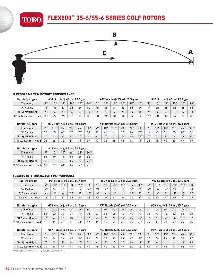
40 | Learn more at www.toro.com/golf
Nozzle/psi/gpm #34 Nozzle @ 65 psi, 30.0 gpm #35 Nozzle @ 65 psi, 32.4 gpm #36 Nozzle @ 80 psi, 34.0 gpm
Trajectory 7° 10° 15° 20° 25° 30° 7° 10° 15° 20° 25° 30° 7° 10° 15° 20° 25° 30°
"A" Radius 58' 60' 63' 67' 74' 70' 59' 61' 64' 70' 76' 74' 64' 68' 76' 80' 84' 82'
"B" Spray Height 4' 4' 6' 11' 14' 17' 4' 5' 7' 11' 15' 17' 5' 7' 9' 14' 17' 22'
"C" Distance from Head 24' 26' 35' 39' 39' 39' 30' 32' 36' 43' 43' 43' 25' 38' 40' 45' 49' 45'
Nozzle/psi/gpm #37 Nozzle @ 80 psi, 39.8 gpm
Trajectory 7° 10° 15° 20° 25° 30°
"A" Radius 65' 69' 78' 82' 86' 84'
"B" Spray Height 5' 7' 9' 14' 18' 22'
"C" Distance from Head 30' 39' 41' 46' 50' 46'
Nozzle/psi/gpm #54 Nozzle @ 65 psi, 31.2 gpm #55 Nozzle @ 65 psi, 33.8 gpm #56 Nozzle @ 80 psi, 35.7 gpm
Trajectory 7° 10° 15° 20° 25° 30° 7° 10° 15° 20° 25° 30° 7° 10° 15° 20° 25° 30°
"A" Radius 58' 60' 63' 67' 74' 70' 59' 62' 66' 70' 76' 77' 72' 73' 75' 82' 85' 82'
"B" Spray Height 5' 6' 8' 10' 15' 17' 6' 6' 9' 11' 15' 17' 5' 7' 9' 14' 17' 22'
"C" Distance from Head 31' 34' 40' 41' 41' 42' 34' 36' 43' 45' 45' 45' 25' 38' 40' 45' 49' 45'
Nozzle/psi/gpm #57 Nozzle @ 80 psi, 41.9 gpm #58 Nozzle @ 80 psi, 46.2 gpm #59 Nozzle @ 80 psi, 53.3 gpm
Trajectory 7° 10° 15° 20° 25° 30° 7° 10° 15° 20° 25° 30° 7° 10° 15° 20° 25° 30°
"A" Radius 72' 74' 77' 83' 89' 85' 75' 77' 83' 87' 92' 88' 77' 78' 84' 89' 96' 92'
"B" Spray Height 5' 7' 9' 14' 18' 22' 6' 7' 10' 15' 18' 22' 7' 8' 11' 16' 21' 25'
"C" Distance from Head 30' 39' 41' 46' 50' 46' 38' 40' 43' 47' 52' 48' 42' 44' 45' 47' 53' 49'Information is for reference only. Actual results may vary.
FLEX800 35-6 TRAJECTORY PERFORMANCE
Nozzle/psi/gpm #31 Nozzle @ 65 psi, 15.5 gpm #32 Nozzle @ 65 psi, 20.5 gpm #33 Nozzle @ 65 psi, 22.9 gpm
Trajectory 7° 10° 15° 20° 25° 30° 7° 10° 15° 20° 25° 30° 7° 10° 15° 20° 25° 30°
"A" Radius 46' 46' 50' 53' 54' 50' 46' 49' 51' 55' 63' 54' 54' 56' 59' 62' 66' 61'
"B" Spray Height 4' 4' 5' 8' 11' 13' 3' 4' 6' 9' 12' 15' 4' 5' 7' 9' 13' 15'
"C" Distance from Head 25' 25' 26' 33' 33' 33' 20' 24' 28' 34' 34' 34' 23' 28' 32' 34' 35' 35'
FLEX800 55-6 TRAJECTORY PERFORMANCE
Nozzle/psi/gpm #51 Nozzle @65 psi, 15.7 gpm #52 Nozzle @65 psi, 20.8 gpm #53 Nozzle @65 psi, 23.4 gpm
Trajectory 7° 10° 15° 20° 25° 30° 7° 10° 15° 20° 25° 30° 7° 10° 15° 20° 25° 30°
"A" Radius 46' 46' 51' 53' 54' 50' 49' 50' 51' 55' 64' 65' 54' 56' 59' 62' 68' 61'
"B" Spray Height 4' 4' 6' 10' 13' 15' 4' 4' 6' 9' 11' 13' 5' 6' 7' 9' 13' 15'
"C" Distance from Head 26' 27' 32' 38' 40' 41' 22' 26' 31' 35' 34' 30' 30' 33' 32' 35' 37' 37'
AC
B
FLEX800™ 35-6/55-6 SERIES GOLF ROTORS

Learn more at www.toro.com/golf | 41
FLEX800 35-6 SERIES PERFORMANCE CHART
BasePressure
Nozzle Set 30
(White)
Nozzle Set 31
(Yellow)
Nozzle Set 32
(Blue)
Nozzle Set 33
(Brown)
Nozzle Set 34
(Orange)
Nozzle Set 35
(Green)
Nozzle Set 36
(Gray)
Nozzle Set 37
(Black)
102-2208 102-4587 102-4588 102-4589 102-0728 102-0729 102-0730 102-4261
Blue Gray Blue Gray Red Gray Orange Gray Orange Gray Blue Gray Blue Gray Orange Gray
102-2925 102-2910 102-2925 102-2910 102-2928 102-2910 102-2926 102-2910 102-2926 102-2910 102-2925 102-2910 102-2925 102-2910 102-2926 102-2910
psi Radius gpm Radius gpm Radius gpm Radius gpm Radius gpm Radius gpm Radius gpm Radius gpm50 42 7.1 52 13.7 61 17.1 64 20.2 69 27.4 — — — — — —65 45 8.7 54 15.5 63 20.5 66 22.9 74 30.0 76 32.4 80 34.0 — —80 46 9.6 57 17.0 67 22.6 70 25.3 77 33.2 79 35.8 84 37.5 86 40.8
100 48 11.2 59 18.9 72 25.2 74 28.2 80 37.0 84 39.9 88 42.5 92 45.3Stator 102-6929 Blue 102-1939 Yellow 102-1940 White
Conversions FLX35-6-3134 FLX35-6-3537
FLEX800 55-6 SERIES PERFORMANCE CHART
BasePressure
Nozzle Set 51
(Yellow)
Nozzle Set 52
(Blue)
Nozzle Set 53
(Brown)
Nozzle Set 54
(Orange)
Nozzle Set 55
(Green)
Nozzle Set 56
(Gray)
Nozzle Set 57
(Black)
Nozzle Set 58
(Red)
Nozzle Set 59
(Beige)
102-4587 102-4588 102-4589 102-0728 102-0729 102-0730 102-4261 102-4260 102-4259
Blue Gray Red Gray Orange Gray Orange Gray Blue Gray Blue Gray Orange Gray Blue Gray Blue Gray
102-2925 102-2910 102-2928 102-2910 102-2926 102-2910 102-2926 102-2910 102-2925 102-2910 102-2925 102-2910 102-2926 102-2910 102-2925 102-2910 102-2925 102-2910
psi Radius gpm Radius gpm Radius gpm Radius gpm Radius gpm Radius gpm Radius gpm Radius gpm Radius gpm50 52 13.9 62 17.4 66 20.7 69 28.6 — — — — — — — — — —65 54 15.7 64 20.8 68 23.4 74 31.2 76 33.8 81 35.7 — — — — — —80 57 17.2 68 22.9 72 25.8 77 34.4 79 37.2 85 39.4 89 43.6 92 47.5 96 57.0
100 59 19.1 73 25.5 76 28.7 80 38.2 84 41.3 89 43.7 94 48.5 95 51.1 100 61.1Stator 102-1939 Yellow 102-1940 White 102-1941
Conver. FLX55-6-5154 FLX55-6-5558 FLX55-6-59
n Not recommended at these pressures. Radius shown in feet. Toro recommends the use of a 11⁄4" swing joint at flows over 25-Gpm (95-LPM). Sprinkler radius data collected in Toro’s zero wind test facility per ASAE standard S398.1.
Actual site conditions must be considered when selecting the appropriate nozzle.All sprinklers are equipped with the selectable pilot valve that allows settings at 50, 65, 80 and 100 psi.
FLEX800™ 35-6/55-6 SERIES GOLF ROTORS
Note: Main Nozzle Adapter Data Located on Pages 54. Back Nozzle Data Located on Page 59.
Main Nozzle AdapterA wide assortment of intermediate and inner nozzles for use in the main nozzle adapter and back nozzle position provide unmatched nozzle flexibility.

42
The New FLEX800 35/55 Series features a dual trajectory main nozzle that provides exceptional nozzle performance at the 25° standard angle position and great performance in windy applications at the 15° low angle position. And the part/full circle drive allows you to adjust the area of coverage to match your seasonal watering needs or meet water rationing mandates in seconds with no additional parts required.
Industry's Largest Nozzle SelectionNozzles from 43’ to 92’ radius plus a wide assortment of back
nozzles lets you put the precise amount of water exactly where
you need it. All nozzles threaded in from front.
Stainless Steel Valve SeatEliminates body damage from rocks and debris. This in-
destructible stainless steel seat is molded to the body and
virtually eliminates body replacements due to seat damage.
Optional Radius Reduction ScrewAllows for fine tuning the radius to exactly the distance you need.
In combination with main nozzle sizing and trajectory adjustment
the radius reduction screw can effectively reduce the sprinkler
throw down to 30’.
True Part and Full-Circle in One(40° - 330° part circle)These sprinklers can be full circle today and part circle tomorrow
allowing you to adjust the area of coverage to match your
seasonal needs or meet water rationing mandates.
FLEX800™ 35/55 SERIES GOLF ROTORS
FEATURES & BENEFITS
Dual TrajectoryThe 25° setting provides maximum distance of throw and the 15° setting provides improved wind performance, radius reduction and obstacle avoidance.
FLX35 FLX55
15°
25°
OR
NEW!

FLX35 CONVERSION UPGRADES
MODELS DESCRIPTION
• FLX35-3134
• FLX35-3537
• FLX35-3134E
• FLX35-3537E
FLX35 w/31–34 Nozzles (#3 Nozzle Installed)FLX35 w/35–37 Nozzles (#5 Nozzle Installed) FLX35 w/31–34 Nozzles (#3 Nozzle Installed), Effluent FLX35 w/35–37 Nozzles (#5 Nozzle Installed), Effluent
FLX55 CONVERSION UPGRADES — RIBBED BODY
MODELS DESCRIPTION
• FLX55-5154 • FLX55-5558 • FLX55-59 • FLX55-5154E • FLX55-5558E
• FLX55-59E• 102-5011
• 102-0950
FLX55 w/51–54 Nozzles (#3 Nozzle Installed)FLX55 w/55–58 Nozzles (#5 Nozzle Installed) FLX55 w/59 NozzleFLX55 w/51–54 Nozzles (#3 Nozzle Installed), EffluentFLX55 w/55–58 Nozzles (#5 Nozzle Installed), EffluentFLX55 w/59 Nozzle, Effluent690 Adapter allows you to upgrade any 690 with FLX55 conversionsRequired to Upgrade all 650, 670, 680, 750, and 780 Series Sprinklers
FLX55 CONVERSION UPGRADES — RIBLESS BODY
MODELS DESCRIPTION
• FLX55-5154R • FLX55-5558R • FLX55-59R • FLX55-5154RE • FLX55-5558RE
• FLX55-59RE
FLX55 w/51–54 Nozzles (#3 Nozzle Installed)FLX55 w/55–58 Nozzles (#5 Nozzle Installed) FLX55 w/59 NozzleFLX55 w/51–54 Nozzles (#3 Nozzle Installed), EffluentFLX55 w/55–58 Nozzles (#5 Nozzle Installed), EffluentFLX55 w/59 Nozzle, Effluent
SPECIFICATIONS Operational• Inlet: - FLX35: 1” ACME - FLX55: 1½” ACME• Radius: - FLX35: 43’ – 83’ - FLX55: 55’ – 92’• Flow Rate: - FLX35: 8.2 – 47.3 gpm - FLX55: 14.1 – 61.3 gpm• Precipitation Rates: - FLX35: Minimum - .41”/hr; Maximum - .45”/hr - FLX55: Minimum - .46”/hr; Maximum - .58”/hr• Pilot Valve: Selectable at 50, 65, 80 and 100 psi• Recommended Operating Pressure Range: 65-100 psi (maximum – 150 Psi and minimum – 40 psi)• Activation types – Electric Valve-in-Head: - Standard Solenoid: n 24 VAC, 50/60 Hz n Inrush: 0.30 A n Holding 0.20 A - Spike Guard Solenoid: n 24 VAC, 50/60 Hz n Inrush: 0.12 A n Holding 0.10 A - Nickel-Plated Spike Guard Solenoid: n 24 VAC, 50/60 Hz n Inrush: 0.12 A n Holding 0.10 A - DC Latching Solenoid (DCLS): n Momentary low voltage pulse - Integrated GDC Module w/DCLS: n Momentary low voltage pulse
Additional Features• FLX35 has eight nozzle variations (30, 31, 32, 33, 34, 35, 36 & 37)• FLX55 has nine nozzle variations (51, 52, 53, 54, 55, 56, 57, 58 & 59)• Three in-line nozzles, rotating stream pattern• Two back nozzle positions• Stator variations: 3• Radius reduction screw 363-4839 for fine tuning• Ratcheting riser• Nozzle base clutching
Warranty• Three years• Five years when installed with Toro Swing Joints
43
Specifying Information—FLEX800 35 & FLEX800 55FLXX5-XXX-X-7
BodyInlet
Arc NozzlePressure
Regulation*Activation Type Optional
FLXX 5 X X X X 73—1" 5—11⁄2"
5—Part-circle and Full-circle In One
FLX35—30, 31, 32, 33, 34, 35, 36, 37FLX55—51, 52, 53, 54, 55, 56, 57, 58, 59
6—65 Psi8—80 Psi1—100 Psi
1—Standard Solenoid2—Spike Guard™ Solenoid3—Nickel-plated Spike Guard Solenoid4—DC Latching Solenoid (DCLS)5—Integrated GDC Module w/DCLS
7—Effluent
Example: When specifying an FLX35-6 Series Sprinkler with #34 nozzle, pressure regulation at 65 Psi and Spike Guard you would specify: FLX35-346-26
Note: Not all models available. * All sprinklers are equipped with the selectable pilot valve that allows settings at 50, 65, 80 and 100 psi.
Dimensions• Body Flange Diameter: - FLX35: 61/2” - FLX55: 71/2”• Body height: - FLX35: 10” - FLX55: 113/8”• Weight: - FLX35: 2.89 lbs. - FLX55: 3.57 lbs. • Weight–Integrated GDC - FLX35: 3.58 lbs. - FLX55: 4.26 lbs. • Pop-up height to nozzle: 3¼”

44 | Learn more at www.toro.com/golf
FLEX800 35 SERIES PERFORMANCE CHART—25°
FrontNozzle
Positions
Nozzle Set 30
(White Plug)
Nozzle Set 31
(Yellow)
Nozzle Set 32
(Blue)
Nozzle Set 33
(Brown)
Nozzle Set 34
(Orange)
Nozzle Set 35
(Green)
Nozzle Set 36
(Gray)
Nozzle Set 37
(Black)
102-2208 102-6906 102-0726 102-6907 102-0728 102-6955 102-6935 102-6936
Yellow Biege Yellow Brown Yellow Yellow Yellow Yellow Yellow Yellow Yellow Green Green Green Green Green
102-5670 102-6942 102-5670 102-5671 102-5670 102-6884 102-5670 102-6884 102-5670 102-6884 102-5670 102-6885 102-6531 102-6885 102-6531 102-6885
BackNozzle
PositionsRed Plug Red Plug Red Plug Red Plug Red Plug Red Plug Red Plug Red Plug Red Plug Red Plug Red Plug Red Plug Red Plug Red Plug Red Plug Red Plug
102-4335 102-4335 102-4335 102-4335 102-4335 102-4335 102-4335 102-4335 102-4335 102-4335 102-4335 102-4335 102-4335 102-4335 102-4335 102-4335
psi Radius gpm Radius gpm Radius gpm Radius gpm Radius gpm Radius gpm Radius gpm Radius gpm
50 43 8.2 53 13.8 56 18.3 61 21.7 65 25.3 — — — — — —65 45 10.0 53 15.5 59 20.5 64 24.4 68 28.2 72 34.1 — — — —80 46 11.5 57 17.3 62 22.7 67 27.1 71 31.1 75 37.8 78 40.3 80 44.0
100 47 13.4 59 19.1 65 24.9 70 29.8 74 34.1 79 40.9 81 43.8 83 47.3
FLEX800 35 NOZZLE APEX
Pressure Nozzle Apex at 15˚ Apex at 25°
65 psi
31 6’ @ 51’ 13’ @ 54’
32 6’ @ 51’ 11’ @ 64’
33 7’ @ 59’ 13’ @ 68’
34 8’ @ 63’ 15’ @ 74’
35 9’ @ 66’ 15’ @ 76’
80 psi36 8’ @ 75’ 18’ @ 83’
37 9’ @ 74’ 19’ @ 82’
FLEX800™ 35/55 SERIES GOLF ROTORS
FLEX800 35 SERIES PERFORMANCE CHART—15°psi Radius gpm Radius gpm Radius gpm Radius gpm Radius gpm Radius gpm Radius gpm Radius gpm50 43 8.2 52 13.6 58 18.1 61 21.5 62 25.6 — — — — — —65 45 10.0 54 15.3 60 20.3 64 24.2 65 27.3 69 33.1 — — — —
80 46 11.5 58 17.2 64 22.6 69 26.8 69 30.2 75 36.8 76 39.7 76 42.9
100 47 13.4 60 19.0 66 24.7 71 29.5 72 32.9 78 39.5 82 42.6 82 46.1
Stator 102-6929 Blue 102-1939 Yellow 102-1940 White
Conversions FLX35-3134 FLX35-3537■ Not recommended at these pressures. Radius shown in feet.
Toro recommends the use of a 11⁄4" swing joint at flows over 25-Gpm (95-LPM). Sprinkler radius data collected in Toro’s zero wind test facility per ASAE standard S398.1.Actual site conditions must be considered when selecting the appropriate nozzle.
All sprinklers are equipped with the selectable pilot valve that allows settings at 50, 65, 80 and 100 psi.
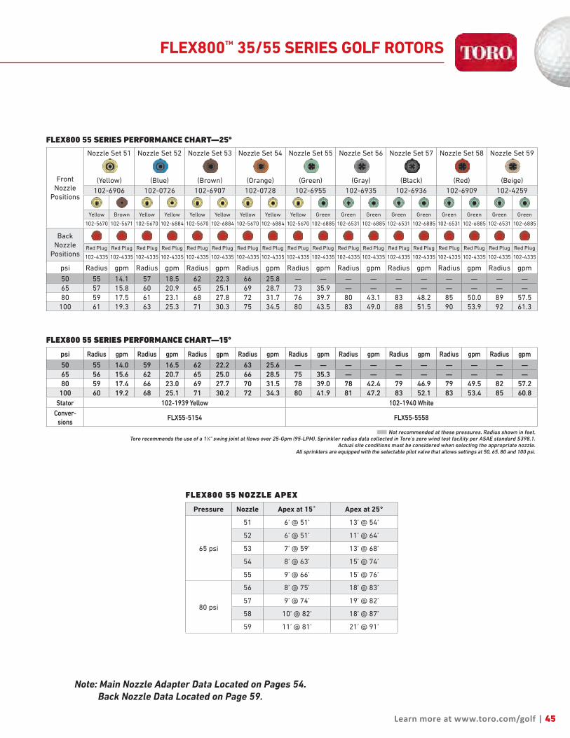
Learn more at www.toro.com/golf | 45
FLEX800 55 SERIES PERFORMANCE CHART—25°
FrontNozzle
Positions
Nozzle Set 51
(Yellow)
Nozzle Set 52
(Blue)
Nozzle Set 53
(Brown)
Nozzle Set 54
(Orange)
Nozzle Set 55
(Green)
Nozzle Set 56
(Gray)
Nozzle Set 57
(Black)
Nozzle Set 58
(Red)
Nozzle Set 59
(Beige)
102-6906 102-0726 102-6907 102-0728 102-6955 102-6935 102-6936 102-6909 102-4259
Yellow Brown Yellow Yellow Yellow Yellow Yellow Yellow Yellow Green Green Green Green Green Green Green Green Green
102-5670 102-5671 102-5670 102-6884 102-5670 102-6884 102-5670 102-6884 102-5670 102-6885 102-6531 102-6885 102-6531 102-6885 102-6531 102-6885 102-6531 102-6885
BackNozzle
PositionsRed Plug Red Plug Red Plug Red Plug Red Plug Red Plug Red Plug Red Plug Red Plug Red Plug Red Plug Red Plug Red Plug Red Plug Red Plug Red Plug Red Plug Red Plug
102-4335 102-4335 102-4335 102-4335 102-4335 102-4335 102-4335 102-4335 102-4335 102-4335 102-4335 102-4335 102-4335 102-4335 102-4335 102-4335 102-4335 102-4335
psi Radius gpm Radius gpm Radius gpm Radius gpm Radius gpm Radius gpm Radius gpm Radius gpm Radius gpm
50 55 14.1 57 18.5 62 22.3 66 25.8 — — — — — — — — — —65 57 15.8 60 20.9 65 25.1 69 28.7 73 35.9 — — — — — — — —80 59 17.5 61 23.1 68 27.8 72 31.7 76 39.7 80 43.1 83 48.2 85 50.0 89 57.5
100 61 19.3 63 25.3 71 30.3 75 34.5 80 43.5 83 49.0 88 51.5 90 53.9 92 61.3
FLEX800 55 NOZZLE APEX
Pressure Nozzle Apex at 15˚ Apex at 25°
65 psi
51 6’ @ 51’ 13’ @ 54’
52 6’ @ 51’ 11’ @ 64’
53 7’ @ 59’ 13’ @ 68’
54 8’ @ 63’ 15’ @ 74’
55 9’ @ 66’ 15’ @ 76’
80 psi
56 8’ @ 75’ 18’ @ 83’
57 9’ @ 74’ 19’ @ 82’
58 10’ @ 82’ 18’ @ 87’
59 11’ @ 81’ 21’ @ 91’
Note: Main Nozzle Adapter Data Located on Pages 54. Back Nozzle Data Located on Page 59.
FLEX800™ 35/55 SERIES GOLF ROTORS
FLEX800 55 SERIES PERFORMANCE CHART—15°
psi Radius gpm Radius gpm Radius gpm Radius gpm Radius gpm Radius gpm Radius gpm Radius gpm Radius gpm
50 55 14.0 59 16.5 62 22.2 63 25.6 — — — — — — — — — —65 56 15.6 62 20.7 65 25.0 66 28.5 75 35.3 — — — — — — — —80 59 17.4 66 23.0 69 27.7 70 31.5 78 39.0 78 42.4 79 46.9 79 49.5 82 57.2
100 60 19.2 68 25.1 71 30.2 72 34.3 80 41.9 81 47.2 83 52.1 83 53.4 85 60.8Stator 102-1939 Yellow 102-1940 White
Conver-sions
FLX55-5154 FLX55-5558
■ Not recommended at these pressures. Radius shown in feet. Toro recommends the use of a 11⁄4" swing joint at flows over 25-Gpm (95-LPM). Sprinkler radius data collected in Toro’s zero wind test facility per ASAE standard S398.1.
Actual site conditions must be considered when selecting the appropriate nozzle.All sprinklers are equipped with the selectable pilot valve that allows settings at 50, 65, 80 and 100 psi.

15°
25°
OR
46
The New FLEX800 34/54 Series with dual trajectory main nozzle provides exceptional nozzle performance at the 25° standard angle position and great performance in windy applications at the 15° low angle position. And the consistency of the constant velocity full circle drive ensures even water application across the coverage area every time you water.
Industry's Largest Nozzle SelectionNozzles from 52’ to 99’ radius plus a wide assortment of back
nozzles lets you put the precise amount of water exactly where
you need it. All nozzles threaded in from front.
Stainless Steel Valve SeatEliminates body damage from rocks and debris. This in-
destructible stainless steel seat is molded to the body and
virtually eliminates body replacements due to seat damage.
Optional Radius Reduction ScrewAllows for fine tuning the radius to exactly the distance you need.
In combination with main nozzle sizing and trajectory adjustment
the radius reduction screw can effectively reduce the sprinkler
throw down to 30’.
Constant Velocity Full Circle DriveEnsures consistent rotation speeds when matched with station
run times for even water application across the coverage area
every time you water.
FLEX800™ 34/54 SERIES GOLF ROTORS
FEATURES & BENEFITS
Dual TrajectoryThe 25° setting provides maximum distance of throw and the 15° setting provides improved wind performance, radius reduction and obstacle avoidance.
FLX34 FLX54
NEW!

FLX34 CONVERSION UPGRADES
MODELS DESCRIPTION
• FLX34-3134
• FLX34-3537
• FLX34-3134E
• FLX34-3537E
FLX34 w/31–34 Nozzles (#3 Nozzle Installed)FLX34 w/35–37 Nozzles (#5 Nozzle Installed) FLX34 w/31–34 Nozzles (#3 Nozzle Installed), Effluent FLX34 w/35–37 Nozzles (#5 Nozzle Installed), Effluent
FLX54 CONVERSION UPGRADES
MODELS DESCRIPTION
• FLX54-5154 • FLX54-5558 • FLX54-59 • FLX54-5154E • FLX54-5558E
• FLX54-59E• 102-5011
• 102-0950
FLX54 w/51–54 Nozzles (#3 Nozzle Installed)FLX54 w/55–58 Nozzles (#5 Nozzle Installed) FLX54 w/59 NozzleFLX54 w/51–54 Nozzles (#3 Nozzle Installed), EffluentFLX54 w/55–58 Nozzles (#5 Nozzle Installed), EffluentFLX55 w/59 Nozzle, Effluent690 Adapter allows you to upgrade any 690 with FLX54 conversionsRequired to Upgrade all 1.5” Series Sprinklers (650, 670, 680, 750, and 780)
SPECIFICATIONS Operational• Inlet: - FLX34: 1” ACME - FLX54: 1½” ACME• Radius: - FLX34: 52’ – 91’ - FLX54: 52’ – 99’• Flow Rate: - FLX34: 13.0 – 46.9 gpm - FLX54: 13.2 - 61.8 gpm• Precipitation Rates: - FLX34: Minimum - .33”/hr; Maximum - .55”/hr - FLX54: Minimum - .33”/hr; Maximum - .61”/hr• Pilot Valve: Selectable at 50, 65, 80 and 100 psi• Recommended Operating Pressure Range: 65-100 psi (maximum-150 psi and minimum-40 psi)• Activation types – Electric Valve-in-Head: - Standard Solenoid: n 24 VAC, 50/60 Hz n Inrush: 0.30 A n Holding 0.20 A - Spike Guard Solenoid: n 24 VAC, 50/60 Hz n Inrush: 0.12 A n Holding 0.10 A - Nickel-Plated Spike Guard Solenoid: n 24 VAC, 50/60 Hz n Inrush: 0.12 A n Holding 0.10 A - DC Latching Solenoid (DCLS): n Momentary low voltage pulse - Integrated GDC Module w/DCLS: n Momentary low voltage pulse• Trajectory: 25° or 15°
Dimensions• Body Flange Diameter: - FLX34: 61/2” - FLX54: 71/2” • Body height: - FLX34: 10” - FLX54: 113/8” • Weight: - FLX34: 2.87 lbs. - FLX54: 3.55 lbs. • Weight–Integrated GDC - FLX34: 3.56 lbs. - FLX54: 4.24 lbs. • Pop-up height to nozzle: 3¼”
Warranty• Three years• Five years when installed with Toro Swing Joints
47
Specifying Information—FLEX800 34 & FLEX800 54FLXX4-XXX-X-7
BodyInlet
Arc NozzlePressure
Regulation*Activation Type Optional
FLXX 4 X X X X 73—1" 5—11⁄2"
4—Part-circle and Full-circle In One
FLX34—30, 31, 32, 33, 34, 35, 36, 37FLX54—51, 52, 53, 54, 55, 56, 57, 58, 59
6—65 Psi8—80 Psi1—100 Psi
1—Standard Solenoid2—Spike Guard™ Solenoid3—Nickel-plated Spike Guard Solenoid4—DC Latching Solenoid (DCLS)5—Integrated GDC Module w/DCLS
7—Effluent
Example: When specifying an FLX34 Series Sprinkler with #34 nozzle, pressure regulation at 65 Psi and Spike Guard you would specify: FLX34–346–2
Note: Not all models available. * All sprinklers are equipped with the selectable pilot valve that allows settings at 50, 65, 80 and 100 psi.
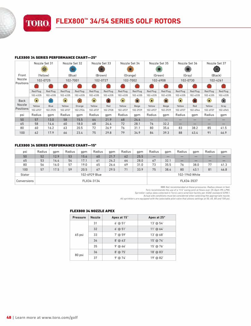
48 | Learn more at www.toro.com/golf
FLEX800 34 SERIES PERFORMANCE CHART—25°
FrontNozzle
Positions
Nozzle Set 31
(Yellow)
Nozzle Set 32
(Blue)
Nozzle Set 33
(Brown)
Nozzle Set 34
(Orange)
Nozzle Set 35
(Green)
Nozzle Set 36
(Gray)
Nozzle Set 37
(Black)
102-0725 102-7001 102-0727 102-7002 102-6908 102-0730 102-4261
Red Plug Red Plug Red Plug Red Plug Red Plug Red Plug Red Plug Red Plug Red Plug Red Plug Red Plug Red Plug Red Plug Red Plug
102-4335 102-4335 102-4335 102-4335 102-4335 102-4335 102-4335 102-4335 102-4335 102-4335 102-4335 102-4335 102-4335 102-4335
BackNozzle
PositionsYellow Blue Yellow Orange Yellow Red Yellow Beige Yellow Beige Yellow Red Yellow Gray
102-6937 102-2925 102-6937 102-2926 102-6937 102-2928 102-6937 102-2929 102-6937 102-2929 102-6937 102-6944 102-6937 102-6945
psi Radius gpm Radius gpm Radius gpm Radius gpm Radius gpm Radius gpm Radius gpm
50 57 13.0 58 15.5 64 21.9 68 24.4 — — — — — —65 58 14.6 60 18.0 68 24.4 72 28.1 76 32.2 — — — —80 60 16.2 63 20.5 72 26.9 76 31.1 80 35.6 83 38.2 85 41.5
100 62 17.9 66 23.4 75 29.8 79 34.9 84 39.3 88 43.4 91 46.9
FLEX800 34 SERIES PERFORMANCE CHART—15°
psi Radius gpm Radius gpm Radius gpm Radius gpm Radius gpm Radius gpm Radius gpm
50 52 12.9 53 15.6 60 21.7 62 25.5 — — — — — —65 53 14.4 54 17.1 61 24.2 64 28.0 67 32.1 — — — —80 56 16.0 57 19.0 65 26.6 69 31.0 73 35.5 76 38.0 77 41.3
100 57 17.5 59 20.5 67 29.5 71 33.9 75 38.4 80 43.1 81 46.8
Stator 102-6929 Blue 102-1940 White
Conversions FLX34-3134 FLX34-3537
■ Not recommended at these pressures. Radius shown in feet. Toro recommends the use of a 11⁄4" swing joint at flows over 25-Gpm (95-LPM).
Sprinkler radius data collected in Toro’s zero wind test facility per ASAE standard S398.1.Actual site conditions must be considered when selecting the appropriate nozzle.
All sprinklers are equipped with the selectable pilot valve that allows settings at 50, 65, 80 and 100 psi.
FLEX800 34 NOZZLE APEX
Pressure Nozzle Apex at 15˚ Apex at 25°
65 psi
31 6’ @ 51’ 13’ @ 54’
32 6’ @ 51’ 11’ @ 64’
33 7’ @ 59’ 13’ @ 68’
34 8’ @ 63’ 15’ @ 74’
35 9’ @ 66’ 15’ @ 76’
80 psi36 8’ @ 75’ 18’ @ 83’
37 9’ @ 74’ 19’ @ 82’
FLEX800™ 34/54 SERIES GOLF ROTORS

Learn more at www.toro.com/golf | 49
FLEX800 54 SERIES PERFORMANCE CHART—25°
FrontNozzle
Positions
Nozzle Set 51
(Yellow)
Nozzle Set 52
(Blue)
Nozzle Set 53
(Brown)
Nozzle Set 54
(Orange)
Nozzle Set 55
(Green)
Nozzle Set 56
(Gray)
Nozzle Set 57
(Black)
Nozzle Set 58
(Red)
Nozzle Set 59
(Beige)
102-0725 102-7001 102-0727 102-7002 102-6908 102-0730 102-4261 102-4260 102-4259
Red Plug Red Plug Red Plug Red Plug Red Plug Red Plug Red Plug Red Plug Red Plug Red Plug Red Plug Red Plug Red Plug Brown Red Plug Brown Red Plug Red Plug
102-4335 102-4335 102-4335 102-4335 102-4335 102-4335 102-4335 102-4335 102-4335 102-4335 102-4335 102-4335 102-4335 102-6883 102-4335 102-6883 102-4335 102-4335
BackNozzle
PositionsYellow Blue Yellow Orange Yellow Red Yellow Beige Yellow Beige Yellow Red Yellow Gray Yellow Gray Yellow Gray
102-6937 102-2925 102-6937 102-2926 102-6937 102-2928 102-6937 102-2929 102-6937 102-2929 102-6937 102-6944 102-6937 102-6945 102-6937 102-6945 102-6937 102-6945
psi Radius gpm Radius gpm Radius gpm Radius gpm Radius gpm Radius gpm Radius gpm Radius gpm Radius gpm
50 58 13.2 59 15.7 64 22.0 70 26.2 — — — — — — — — — —65 60 14.8 61 17.5 68 24.8 74 29.3 79 34.2 — — — — — — — —80 61 16.4 64 20.0 72 27.6 78 32.6 83 38.0 85 40.7 87 44.9 91 50.2 96 55.6
100 63 18.1 67 23.6 75 30.4 81 36.7 87 42.5 90 45.8 93 50.2 95 55.4 99 61.8
FLEX800 54 SERIES PERFORMANCE CHART—15°
psi Radius gpm Radius gpm Radius gpm Radius gpm Radius gpm Radius gpm Radius gpm Radius gpm Radius gpm
50 52 13.2 53 15.8 61 22.0 65 26.0 — — — — — — — — — —65 53 14.8 54 17.4 63 24.8 67 29.2 69 34.1 — — — — — — — —80 56 16.4 58 19.4 68 27.6 72 32.5 75 37.8 79 40.4 81 44.6 85 49.9 87 55.3
100 58 18.1 60 21.1 71 30.4 75 36.4 79 42.3 84 45.5 87 49.9 89 55.1 94 61.5
Stator 102-6929 Blue 102-1940 White 102-1941 White
Conversions FLX54-5154 FLX54-5558 FLX54-59
■ Not recommended at these pressures. Radius shown in feet. Toro recommends the use of a 11⁄4" swing joint at flows over 25-Gpm (95-LPM).
Sprinkler radius data collected in Toro’s zero wind test facility per ASAE standard S398.1.Actual site conditions must be considered when selecting the appropriate nozzle.
All sprinklers are equipped with the selectable pilot valve that allows settings at 50, 65, 80 and 100 psi.
FLEX800 54 NOZZLE APEX
Pressure Nozzle Apex at 15˚ Apex at 25°
65 psi
51 6’ @ 51’ 13’ @ 54’
52 6’ @ 51’ 11’ @ 64’
53 7’ @ 59’ 13’ @ 68’
54 8’ @ 63’ 15’ @ 74’
55 9’ @ 66’ 15’ @ 76’
80 psi
56 8’ @ 75’ 18’ @ 83’
57 9’ @ 74’ 19’ @ 82’
58 10’ @ 82’ 18’ @ 87’
59 11’ @ 81’ 21’ @ 91’
FLEX800™ 34/54 SERIES GOLF ROTORS
Note: Main Nozzle Adapter Data Located on Pages 54. Back Nozzle Data Located on Page 59.
Main Nozzle AdapterA wide assortment of intermediate and inner nozzles for use in the main nozzle adapter and back nozzle position provide unmatched nozzle flexibility.

50
The FLEX800™ B Series golf sprinkler family brings you all the great features and performance of the FLEX800 35-6, 34 and 35 Series sprinklers in a more economical body package specifically designed for block systems. With its rugged golf body design, small exposed surface diameter, flanged body for stability and check valve these sprinklers are perfect for every golf application.
Industry's Largest Nozzle SelectionNozzles from 25’ to 95’ radius, plus a wide assortment of
intermediate and inner nozzles, provide unmatched flexibility
allowing you to put the precise amount of water exactly where you
need it. All nozzles are color-coded, debris tolerant, and thread in
from front.
True Part and Full-Circle in One(40° - 330° part circle)These sprinklers can be full circle or part circle allowing you to
adjust the area of coverage to match your seasonal needs or meet
water rationing mandates.
Flanged Cap Installs Below GradeStabilizes the body position and maintains optimum nozzle
performance.
Small Exposed DiameterMinimizes the appearance of the sprinkler to maximize the beauty
of the course. Perfect for high traffic areas like tees, greens and
surrounds.
FLEX800™ 35-6B/34B/35B SERIES GOLF ROTORS
FEATURES & BENEFITS
NEW!
FLX35-6B FLX34B
FLX35B

SPECIFICATIONS Operational• Inlet: 1” NPT, BSP or ACME• Radius: - FLX35-6B: 42’ – 95’ - FLX35B: 43’ – 90’ - FLX34B: 57’ – 95’• Flow Rate: - FLX35-6B : 7.1 – 52.5 gpm - FLX35B: 8.2 – 56.3 gpm - FLX34B : 13.0 – 55.4 gpm• Precipitation Rates: - FLX35-6B : Minimum - .34”/hr; Maximum - .56”/hr - FLX35B: Minimum - .37”/hr; Maximum - .67”/hr - FLX34B : Minimum - .33”/hr; Maximum - .59”/hr• Recommended Operating Pressure Range: 50-100 psi (maximum – 150 psi and minimum – 40 psi)• Check-O-Matic models maintain up to 5’ elevation change°
Nozzle Selection• Nozzle variations - FLX35-6B - Nine variations (30, 31, 32, 33, 34, 35, 36, 37 & 38) - FLX34B - Nine variations (30, 31, 32, 33, 34, 35, 36, 37 & 38) - FLX54B – Eight variations (31, 32, 33, 34, 35, 36, 37 & 38) • Back nozzle capability on part circle models standard - FLX35-6B – one position available - FLX35B – two positions available - FLX34B – two additional front nozzle positions• Main-less capability for short radius applications• Stator variations - 2• Radius reduction screw for fine tuning the radius (363-4839). Optional on: FLX35B, FLX34B and not available on FLX35-6B models• Ratcheting riser – Part circle models• Nozzle base clutching – Part circle models
Dimensions• Body diameter: 6”• Body height: 8.5”• Weight: - FLX34B – 1.98 lbs. - FLX35B – 2.00 lbs. - FLX35-6B – 2.05 lbs.• Pop-up height to nozzle: 3¼”
Warranty• Three years• Five years when installed with Toro Swing Joints
51
Specifying Information—FLEX800 B SeriesFLX3XB-X2-XXXXE
Series Arc System Thread Type Valve Type Nozzle OptionalFLX3 X B X 2 XXXX E
FLX3 – FLEX800 B Series
4—Full-Circle5—Part-/Full-Circle5-6—Part-/Full-Circle with TruJectory
B—Block 0—NPT 4—ACME5—BSP
Check-O-Matic 3134— Includes nozzles #31, 32, 33 & 343538— Includes nozzles #35, 36, 37 & 38
E—Effluent Model
Example: When specifying a FLEX800 B Series Sprinkler with full circle – NPT threads #34 nozzles, you would specify: FLX34B-02-3134
Main Nozzle AdapterA wide assortment of intermediate and inner nozzles for use in the main nozzle adapter and back nozzle position provide unmatched nozzle flexibility.
7°
30°
Nozzle Trajectory Provides Unmatched PerformanceFLX35-6B with TruJectory™ adjustment from 7°-30° in 1° increments and FLX35/FLX34 models with dual trajectory settings of 25° or 15° provide improved wind performance, obstacle avoidance and radius adjustment.
FLX35-6B
15°
25°
FLX34B and FLX35B
OR

FLEX800™ 35-6B/34B/35B SERIES GOLF ROTORS
FLEX800 35-6B SERIES PERFORMANCE CHART—25°
BasePressure
Nozzle Set 30
(White)102-2208
Nozzle Set 31
(Yellow)
102-4587
Nozzle Set 32
(Blue)
102-4588
Nozzle Set 33
(Brown)
102-4589
Nozzle Set 34
(Orange)
102-0728
Nozzle Set 35
(Green)102-0729
Nozzle Set 36
(Gray)102-0730
Nozzle Set 37
(Black)102-4261
Nozzle Set 38
(Red)102-6909
Blue
Gray
Blue
Gray Red Gray Orange
Gray Orange Gray Blue
Gray Blue
Gray Orange
Gray Blue
Gray
102-2925 102-2910 102-2925 102-2910 102-2928 102-2910 102-2926 102-2910 102-2926 102-2910 102-2925 102-2910 102-2925 102-2910 102-2926 102-2910 102-2925 102-2910
Back Nozzle 102-4335 Red Plug
psi Radius gpm Radius gpm Radius gpm Radius gpm Radius gpm Radius gpm Radius gpm Radius gpm Radius gpm
50 42 7.1 52 14.0 58 18.0 — — — — — — — — — — — —
60 43 7.9 54 15.2 60 19.5 66 21.9 — — — — — — — — — —
70 45 8.8 55 16.4 63 21.0 68 23.6 74 32.7 77 35.2 — — — — — —
80 46 9.6 57 17.4 65 22.6 70 25.3 77 35.1 79 37.7 84 39.6 86 43.4 90 47.5
90 47 10.4 58 18.5 68 23.9 72 26.8 79 37.0 82 9.9 86 41.9 88 45.9 93 50.0
100 48 11.2 59 19.4 70 25.2 74 28.2 80 38.9 84 41.8 88 44.1 90 48.4 95 52.5
Stator 102-6929 Blue 102-1939 Yellow 102-1940 White
Conversions INF35-6-3134 INF35-6-3537
FLEX800 B Series with mainless short radius nozzle configuration.
52

FLEX800™ 35-6B/34B/35B SERIES GOLF ROTORS
FLEX800 35B SERIES PERFORMANCE CHART—25°
FrontNozzle
Positions
Nozzle Set 30
(White Plug)102-2208
Nozzle Set 31
(Yellow)102-6906
Nozzle Set 32
(Blue)
102-0726
Nozzle Set 33
(Brown)102-6907
Nozzle Set 34
(Orange)102-0728
Nozzle Set 35
(Green)
102-6955
Nozzle Set 36
(Gray)
102-6935
Nozzle Set 37
(Black)102-6936
Nozzle Set 38
(Red)102-6909
Yellow Biege Yellow Brown Yellow Yellow Yellow Yellow Yellow Yellow Yellow Green Green Green Green Green Green Green
102-5670 102-6942 102-5670 102-5671 102-5670 102-6884 102-5670 102-6884 102-5670 102-6884 102-5670 102-6885 102-6531 102-6885 102-6531 102-6885 102-6531 102-6885
Back Nozzles 102-4335 Red Plug
psi Radius gpm Radius gpm Radius gpm Radius gpm Radius gpm Radius gpm Radius gpm Radius gpm Radius gpm
50 43 8.2 55 13.6 56 18.3 — — — — — — — — — — — —
60 44 9.3 56 15.0 58 20.1 63 24.2 — — — — — — — — — —
70 45 10.4 58 16.2 60 21.8 65 26.3 69 30.0 73 37.0 — — — — — —
80 46 11.5 59 17.3 62 23.3 67 28.0 71 32.1 75 39.6 78 42.9 80 48.6 85 50.6
90 47 12.5 60 18.4 64 24.7 69 29.8 73 34.2 77 42.0 80 45.4 82 51.5 88 53.6
100 47 13.4 61 19.3 65 26.0 70 31.4 74 35.9 79 44.2 81 48.8 83 54.2 90 56.3
Stator 102-6929 Blue 102-1939 Yellow 102-1940 White
Conversions FLX35-3134 FLX35-3537
FLEX800 34B SERIES PERFORMANCE CHART—25°
FrontNozzle
Positions
Nozzle Set 31
(Yellow)
102-0725
Nozzle Set 32
(Blue)102-7001
Nozzle Set 33
(Brown)
102-0727
Nozzle Set 34
(Orange)
102-7002
Nozzle Set 35
(Green)
102-6908
Nozzle Set 36
(Gray)
102-0730
Nozzle Set 37
(Black)
102-4261
Nozzle Set 38
(Red)
102-4260
Front Nozzles 102-4335 Red Plug
BackNozzle
PositionsYellow Blue Yellow Orange Yellow Red Yellow Beige Yellow Beige Yellow Red Yellow Gray Yellow Gray
102-6937 102-2925 102-6937 102-2926 102-6937 102-2928 102-6937 102-2929 102-6937 102-2929 102-6937 102-6944 102-6937 102-6945 102-6937 102-6945
psi Radius gpm Radius gpm Radius gpm Radius gpm Radius gpm Radius gpm Radius gpm Radius gpm
50 57 13.0 58 15.5 — — — — — — — — — — — —
60 58 14.1 60 17.2 67 23.6 — — — — — — — — — —
70 59 15.5 61 18.2 69 26.2 73 30.0 78 35.7 — — — — — —
80 60 16.2 63 20.5 72 27.9 76 32.1 80 38.2 83 40.9 85 42.1 91 50.2
90 61 17.5 65 22.0 74 29.7 78 34.1 82 40.5 86 43.4 88 44.5 93 52.8
100 62 18.8 66 23.4 75 31.4 79 36.0 84 42.7 88 45.8 91 46.9 95 55.4
Stator 102-6929 Blue 102-1940 White
Conversions FLX34-3134 FLX34-3537
■ Not recommended at these pressures. Radius shown in feet. Toro recommends the use of a 11⁄4" swing joint at flows over 25-Gpm (95-LPM). Sprinkler radius data collected in Toro’s zero wind test facility per ASAE standard S398.1.
Actual site conditions must be considered when selecting the appropriate nozzle.All sprinklers are equipped with the selectable pilot valve that allows settings at 50, 65, 80 and 100 psi.
53
Note: Main Nozzle Adapter Data Located on Pages 54. Back Nozzle Data Located on Page 59.

MAIN NOZZLE ADAPTER
INTERMEDIATE NOZZLE PERFORMANCE CHARTS
Performance Charts
102-2929Beige
Trajectory 30° 25° 20° 15° 10° 7°
Pressure Flow Radius Radius Radius Radius Radius RadiusPsi BAR Gpm lpm Feet Meters Feet Meters Feet Meters Feet Meters Feet Meters Feet Meters50 3.4 8.1 30.7 53 17.4 52 17.1 50 16.4 48 15.7 45 14.8 42 13.860 4.1 8.9 33.7 57 18.7 56 18.4 53 17.4 51 16.7 47 15.4 45 14.865 4.5 9.3 35.2 58 19.0 56 18.4 54 17.7 51 16.7 49 16.1 46 15.170 4.8 9.6 36.3 59 19.4 57 18.7 56 18.4 53 17.4 50 16.4 48 15.780 5.5 10.3 39.0 61 20.0 60 19.7 58 19.0 56 18.4 53 17.4 50 16.490 6.2 10.9 41.3 63 20.7 61 20.0 59 19.4 57 18.7 54 17.7 51 16.7
100 6.9 11.5 43.5 65 21.3 63 20.7 60 19.7 58 19.0 55 18.0 51 16.7
102-2927Gray
Trajectory 30° 25° 20° 15° 10° 7°
Pressure Flow Radius Radius Radius Radius Radius RadiusPsi BAR Gpm lpm Feet Meters Feet Meters Feet Meters Feet Meters Feet Meters Feet Meters50 3.4 5.0 18.9 50 16.4 48 15.7 46 15.1 44 14.4 41 13.5 38 12.560 4.1 5.5 20.8 52 17.1 50 16.4 48 15.7 46 15.1 43 14.1 40 13.165 4.5 5.7 21.6 53 17.4 51 16.7 49 16.1 46 15.1 44 14.4 41 13.570 4.8 5.9 22.3 53 17.4 51 16.7 49 16.1 47 15.4 45 14.8 42 13.880 5.5 6.3 23.8 54 17.7 52 17.1 50 16.4 48 15.7 46 15.1 43 14.190 6.2 6.7 25.4 55 18.0 53 17.4 52 17.1 50 16.4 48 15.7 45 14.8
100 6.9 7.1 26.9 55 18.0 54 17.7 53 17.4 52 17.1 50 16.4 46 15.1
102-2928Red
Trajectory 30° 25° 20° 15° 10° 7°
Pressure Flow Radius Radius Radius Radius Radius RadiusPsi BAR Gpm lpm Feet Meters Feet Meters Feet Meters Feet Meters Feet Meters Feet Meters50 3.4 6.3 23.8 53 17.4 51 16.7 48 15.7 46 15.1 43 14.1 40 13.160 4.1 7.0 26.5 55 18.0 53 17.4 50 16.4 48 15.7 45 14.8 42 13.865 4.5 7.2 27.3 56 18.4 54 17.7 52 17.1 49 16.1 47 15.4 44 14.470 4.8 7.5 28.4 57 18.7 55 18.0 53 17.4 51 16.7 49 16.1 46 15.180 5.5 8.0 30.3 59 19.4 58 19.0 56 18.4 54 17.7 52 17.1 49 16.190 6.2 8.5 32.2 60 19.7 58 19.0 57 18.7 55 18.0 53 17.4 50 16.4
100 6.9 9.0 34.1 61 20.0 59 19.4 57 18.7 55 18.0 53 17.4 50 16.4
102-2926Orange
Trajectory 30° 25° 20° 15° 10° 7°
Pressure Flow Radius Radius Radius Radius Radius RadiusPsi BAR Gpm lpm Feet Meters Feet Meters Feet Meters Feet Meters Feet Meters Feet Meters50 3.4 4.3 16.3 48 15.7 46 15.1 44 14.4 42 13.8 39 12.8 35 11.560 4.1 4.7 17.8 50 16.4 48 15.7 46 15.1 44 14.4 41 13.5 38 12.565 4.5 4.9 18.5 51 16.7 49 16.1 47 15.4 45 14.8 42 13.8 39 12.870 4.8 5.1 19.3 51 16.7 50 16.4 48 15.7 46 15.1 43 14.1 40 13.180 5.5 5.4 20.4 52 17.1 51 16.7 50 16.4 48 15.7 45 14.8 42 13.890 6.2 5.8 22.0 53 17.4 52 17.1 51 16.7 49 16.1 47 15.4 44 14.4
100 6.9 6.1 23.1 54 17.7 53 17.4 52 17.1 50 16.4 48 15.7 45 14.8
102-2925Blue
Trajectory 30° 25° 20° 15° 10° 7°
Pressure Flow Radius Radius Radius Radius Radius RadiusPsi BAR Gpm lpm Feet Meters Feet Meters Feet Meters Feet Meters Feet Meters Feet Meters50 3.4 2.7 10.2 42 13.8 41 13.5 39 12.8 38 12.5 36 11.8 34 11.260 4.1 3.0 11.4 43 14.1 42 13.8 40 13.1 39 12.8 37 12.1 35 11.565 4.5 3.2 12.1 43 14.1 42 13.8 40 13.1 39 12.8 37 12.1 35 11.570 4.8 3.3 12.5 44 14.4 42 13.8 41 13.5 39 12.8 38 12.5 36 11.880 5.5 3.5 13.2 44 14.4 43 14.1 41 13.5 40 13.1 38 12.5 36 11.890 6.2 3.7 14.0 45 14.8 44 14.4 42 13.8 41 13.5 39 12.8 37 12.1
100 6.9 3.9 14.8 45 14.8 44 14.4 43 14.1 42 13.8 40 13.1 38 12.5
54

MAIN NOZZLE ADAPTER
INNER NOZZLE PERFORMANCE CHARTS*
102-6885Green
Trajectory 30° 25° 20° 15° 10° 7°
Pressure Flow Radius Radius Radius Radius Radius RadiusPsi BAR Gpm lpm Feet Meters Feet Meters Feet Meters Feet Meters Feet Meters Feet Meters50 3.4 5.4 20.4 51 16.7 50 16.4 48 15.7 45 14.8 42 13.8 39 12.860 4.1 5.9 22.3 52 17.1 51 16.7 49 16.1 46 15.1 43 14.1 41 13.565 4.5 6.1 23.1 52 17.1 51 16.7 50 16.4 47 15.4 44 14.4 42 13.870 4.8 6.3 23.8 53 17.4 52 17.1 50 16.4 47 15.4 44 14.4 42 13.880 5.5 6.7 25.4 53 17.4 52 17.1 51 16.7 48 15.7 45 14.8 43 14.190 6.2 7.1 26.9 54 17.7 53 17.4 52 17.1 50 16.4 47 15.4 45 14.8
100 6.9 7.4 28.0 55 18.0 55 18.0 54 17.7 52 17.1 49 16.1 47 15.4
102-6884Yellow
Trajectory 30° 25° 20° 15° 10° 7°
Pressure Flow Radius Radius Radius Radius Radius RadiusPsi BAR Gpm lpm Feet Meters Feet Meters Feet Meters Feet Meters Feet Meters Feet Meters50 3.4 4.1 15.5 48 15.7 47 15.4 45 14.8 41 13.5 38 12.5 35 11.560 4.1 4.5 17.0 49 16.1 48 15.7 47 15.4 44 14.4 41 13.5 38 12.565 4.5 4.7 17.8 50 16.4 49 16.1 48 15.7 45 14.8 42 13.8 39 12.870 4.8 4.8 18.2 50 16.4 49 16.1 48 15.7 45 14.8 43 14.1 40 13.180 5.5 5.1 19.3 51 16.7 50 16.4 49 16.1 47 15.4 44 14.4 41 13.590 6.2 5.4 20.4 53 17.4 52 17.1 50 16.4 48 15.7 45 14.8 42 13.8
100 6.9 5.8 22.0 54 17.7 53 17.4 51 16.7 49 16.1 46 15.1 43 14.1
102-6883Brown
Trajectory 30° 25° 20° 15° 10° 7°
Pressure Flow Radius Radius Radius Radius Radius RadiusPsi BAR Gpm lpm Feet Meters Feet Meters Feet Meters Feet Meters Feet Meters Feet Meters50 3.4 2.4 9.1 41 13.5 40 13.1 38 12.5 36 11.8 33 10.8 30 9.860 4.1 2.6 9.8 43 14.1 42 13.8 40 13.1 38 12.5 36 11.8 33 10.865 4.5 2.7 10.2 44 14.4 42 13.8 41 13.5 39 12.8 37 12.1 34 11.270 4.8 2.8 10.6 45 14.8 43 14.1 42 13.8 40 13.1 38 12.5 35 11.580 5.5 3.0 11.4 46 15.1 45 14.8 43 14.1 41 13.5 40 13.1 36 11.890 6.2 3.2 12.1 46 15.1 45 14.8 44 14.4 42 13.8 41 13.5 37 12.1
100 6.9 3.4 12.9 46 15.1 45 14.8 44 14.4 43 14.1 41 13.5 38 12.5
102-6937Yellow
Trajectory 30° 25° 20°
Pressure Flow Radius Radius RadiusPsi BAR Gpm lpm Feet Meters Feet Meters Feet Meters50 3.4 3.7 14.0 26 8.5 24 7.9 20 6.660 4.1 4.0 15.1 28 9.2 25 8.2 22 7.265 4.5 4.2 15.9 28 9.2 25 8.2 22 7.270 4.8 4.4 16.7 28 9.2 26 8.5 23 7.580 5.5 4.7 17.8 28 9.2 26 8.5 24 7.990 6.2 5.0 18.9 29 9.5 27 8.9 25 8.2
100 6.9 5.2 19.7 30 9.8 29 9.5 27 8.9
102-6531Green
Trajectory 30° 25° 20°
Pressure Flow Radius Radius RadiusPsi BAR Gpm lpm Feet Meters Feet Meters Feet Meters50 3.4 4.0 15.1 32 10.5 30 9.8 26 8.560 4.1 4.3 16.3 34 11.2 31 10.2 27 8.965 4.5 4.5 17.0 34 11.2 31 10.2 27 8.970 4.8 4.7 17.8 34 11.2 31 10.2 28 9.280 5.5 5.0 18.9 34 11.2 32 10.5 29 9.590 6.2 5.3 20.1 34 11.2 32 10.5 29 9.5
100 6.9 5.6 21.2 35 11.5 33 10.8 30 9.8* Not recommended below 20°
Main Nozzle AdaptorP/N 118-1521
55
INTERMEDIATE NOZZLE PERFORMANCE CHARTS
Performance Charts

56
The Toro FLEX800™ R Series Conversion Upgrades enable customers with existing Rain Bird® Eagle™ 900 and 1100 Series sprinklers to upgrade to Toro’s industry leading sprinkler technology. The benefits of upgrading include the patented TruJectory™ adjustment, full and part circle in the same sprinkler, the ability to ratchet the riser and clutch the nozzle base, and an extra 1½” pop-up height.
Industry's Largest Nozzle SelectionNozzles from 42’ to 100’ radius plus a wide assortment of back
nozzles lets you put the precise amount of water exactly where
you need it.
20,000 Volt Lightning RatingSpike Guard™ solenoid virtually eliminates the need for
replacements in high lightning areas. Draws half the amperage
of traditional solenoids so you can run twice as many sprinklers
simultaneously, reduce the cost of wire during installation or
increase the distance from controller to sprinkler.
Dual TruJectoryThe 25° setting provides maximum distance of throw and the 15°
setting provides improved wind performance, radius reduction
and obstacle avoidance (FLX54RB and FLX55RB).
True Full-Circle in One (40° - 330° part circle)These sprinklers can be full circle today and part circle tomorrow
allowing you to simply and economically adjust the area of
coverage to match your seasonal needs or meet water rationing
mandates (FLX55-6RB and FLX55RB).
FLEX800™ R SERIES CONVERSION UPGRADES
FEATURES & BENEFITS
Adds 1½” of Pop-up Height
Left: Rain Bird Eagle 900
Right: Rain Bird Eagle 900 upgraded with Toro R Series upgrade assembly and optional Spike Guard solenoid/adapter
20,000 Volt Lightning Rating
FLX55-6RBFLX55RB
FLX54RB
NEW!
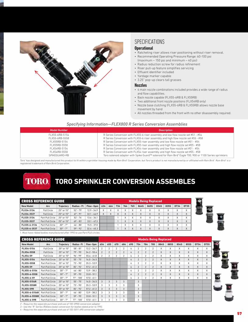
SPECIFICATIONS Operational• Ratcheting riser allows riser positioning without riser removal.• Recommended Operating Pressure Range: 60-100 psi (maximum – 150 psi and minimum – 40 psi)• Radius reduction screw for radius refinement• Riser pull-up feature simplifies servicing• Effluent identifier included• Yardage marker capable• 3.25” pop-up clears tall grasses
Nozzles• 4 main nozzle combinations included provides a wide range of radius
and flow capabilities.• Back nozzle capable (FLX55-6RB & FLX55RB)• Two additional front nozzle positions (FLX54RB only)• Nozzle base clutching (FLX55-6RB & FLX55RB) allows nozzle base
movement by hand• All nozzles threaded from the front with no other disassembly required.
57
Specifying Information—FLEX800 R Series Conversion AssembliesModel Number Description
FLX55-6RB-5154 FLX55-6RB-5558 FLX55RB-5154 FLX55RB-5558 FLX54RB-5154 FLX54RB-5558
SPIKEGUARD-RB
R Series Conversion with FLX55-6 riser assembly and low flow nozzle set #51 - #54 R Series Conversion with FLX55-6 riser assembly and high flow nozzle set #55 - #58 R Series Conversion with FLX55 riser assembly and low flow nozzle set #51 - #54R Series Conversion with FLX55 riser assembly and high flow nozzle set #55 - #58R Series Conversion with FLX54 riser assembly and low flow nozzle set #51 - #54R Series Conversion with FLX54 riser assembly and high flow nozzle set #55 - #58Toro solenoid adapter with Spike Guard™ solenoid for Rain Bird® Eagle 700, 900 or 1100 Series sprinklers
Toro® has designed and manufactured this product to fit within a sprinkler housing made by Rain Bird® Corporation, but Toro’s product is not manufactured by or affiliated with Rain Bird®. Rain Bird® is a registered trademark of Rain Bird Corporation.
CROSS REFERENCE GUIDE Models Being Replaced
New Model Arc Trajectory Radius - Ft Flow - Gpm 634 664 734 764 765 864S 865S 834S 835S DT34 DT35
FLX34-3134 Full Circle 25° or 15° 52' - 79' 12.9 - 34.9 X X X X X X X X X X X
FLX34-3537 Full Circle 25° or 15° 67' - 91' 32.1 - 46.9 X X X X X X X X X X X
FLX35-3134 Part/Full Circle 25° or 15° 52' - 74' 13.6 - 34.1 1 X X X X X X X X
FLX35-3537 Part/Full Circle 25° or 15° 69' - 83' 33.1 - 47.3 1 X X X X X X X X
FLX35-6-3134 Part/Full Circle 30° - 7° 46' - 80' 15.5 - 37.0 1 X X X X X X X X
FLX35-6-3537 Part/Full Circle 30° - 7° 59' - 92' 32.4 - 45.3 1 X X X X X X X X
1. Must have ribbed bodies manufactured after 1992 to use Part/Full circles.
CROSS REFERENCE GUIDE Models Being Replaced
New Model Arc Trajectory Radius - Ft Flow - Gpm 654 655 670 684 690 754 784 785 884S 885S 854S 855S DT54 DT55
FLX54-5154 Full Circle 25° or 15° 58' - 81' 13.2 - 36.7 2 2 2 2 4 2 2 2 X X X X X X
FLX54-5558 Full Circle 25° or 15° 79' - 95' 34.2 - 55.4 2 2 2 2 4 2 2 2 X X X X X X
FLX54-59 Full Circle 25° or 15° 96' - 99' 55.6 - 61.8 2 2 2 2 4 2 2 2 X X X X X X
FLX55-5154 Part/Full Circle 25° or 15° 55' - 75' 14.0 - 34.5 4 2 2 2 X X X X X X
FLX55-5558 Part/Full Circle 25° or 15° 73' - 90' 35.3 - 53.9 4 2 2 2 X X X X X X
FLX55-59 Part/Full Circle 25° or 15° 82' - 92' 57.2 - 61.3 4 2 2 2 X X X X X X
FLX55-6-5154 Part/Full Circle 30° - 7° 46' - 80' 13.9 - 38.2 4 2 2 2 X X X X X X
FLX55-6-5558 Part/Full Circle 30° - 7° 59' - 95' 33.8 - 51.1 4 2 2 2 X X X X X X
FLX55-6-59 Part/Full Circle 30° - 7° 77' - 100' 57.0 - 61.1 4 2 2 2 X X X X X X
FLX55-5154R Part/Full Circle 25° or 15° 55' - 75' 14.0 - 34.5 3 3 3 3 3
FLX55-5558R Part/Full Circle 25° or 15° 73' - 90' 35.3 - 53.9 3 3 3 3 3
FLX55-59R Part/Full Circle 25° or 15° 82' - 92' 57.2 - 61.3 3 3 3 3 3
FLX55-6-5154R Part/Full Circle 30° - 7° 46' - 80' 13.9 - 38.2 3 3 3 3 3
FLX55-6-5558R Part/Full Circle 30° - 7° 59' - 95' 33.8 - 51.1 3 3 3 3 3
FLX55-6-59R Part/Full Circle 30° - 7° 77' - 100' 57.0 - 61.1 3 3 3 3 3
2 - Requires the separate purchase and use of 102-0950 conversion adapter3 - Use the "R" Series (Ribless body) conversion for bodies dated prior to 1992.4 - Requires the separate purchase and use of 102-5011 690 conversion adapter
TORO SPRINKLER CONVERSION ASSEMBLES
57
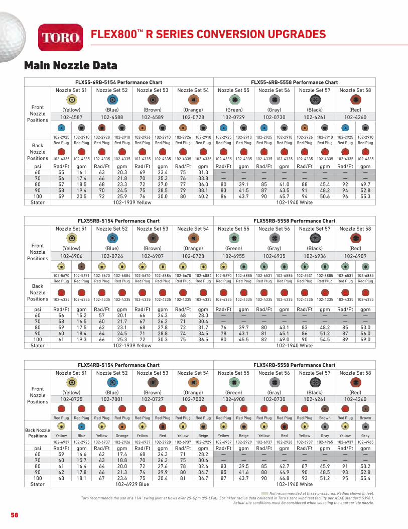
FLEX800™ R SERIES CONVERSION UPGRADES
FLX55-6RB-5154 Performance Chart FLX55-6RB-5558 Performance Chart
Front Nozzle
Positions
Nozzle Set 51
(Yellow)
Nozzle Set 52
(Blue)
Nozzle Set 53
(Brown)
Nozzle Set 54
(Orange)
Nozzle Set 55
(Green)
Nozzle Set 56
(Gray)
Nozzle Set 57
(Black)
Nozzle Set 58
(Red)
102-4587 102-4588 102-4589 102-0728 102-0729 102-0730 102-4261 102-4260
102-2925 102-2910 102-2928 102-2910 102-2926 102-2910 102-2926 102-2910 102-2925 102-2910 102-2925 102-2910 102-2926 102-2910 102-2925 102-2910
Back Nozzle
Positions
Red Plug Red Plug Red Plug Red Plug Red Plug Red Plug Red Plug Red Plug Red Plug Red Plug Red Plug Red Plug Red Plug Red Plug Red Plug Red Plug
102-4335 102-4335 102-4335 102-4335 102-4335 102-4335 102-4335 102-4335 102-4335 102-4335 102-4335 102-4335 102-4335 102-4335 102-4335 102-4335
psi Rad/Ft gpm Rad/Ft gpm Rad/Ft gpm Rad/Ft gpm Rad/Ft gpm Rad/Ft gpm Rad/Ft gpm Rad/Ft gpm60 55 16.1 63 20.3 69 23.4 75 31.3 — — — — — — — —70 56 17.4 66 21.8 70 25.3 76 33.8 — — — — — — — —80 57 18.5 68 23.3 72 27.0 77 36.0 80 39.1 85 41.0 88 45.4 92 49.790 58 19.4 70 24.5 75 28.5 79 38.1 83 41.5 87 43.5 91 48.2 94 52.8
100 59 20.5 72 25.9 76 30.0 80 40.2 86 43.7 90 45.7 94 50.6 96 55.3Stator 102-1939 Yellow 102-1940 White
FLX55RB-5154 Performance Chart FLX55RB-5558 Performance Chart
Front Nozzle
Positions
Nozzle Set 51
(Yellow)
Nozzle Set 52
(Blue)
Nozzle Set 53
(Brown)
Nozzle Set 54
(Orange)
Nozzle Set 55
(Green)
Nozzle Set 56
(Gray)
Nozzle Set 57
(Black)
Nozzle Set 58
(Red)
102-6906 102-0726 102-6907 102-0728 102-6955 102-6935 102-6936 102-6909
102-5670 102-5671 102-5670 102-6884 102-5670 102-6884 102-5670 102-6884 102-5670 102-6885 102-6531 102-6885 102-6531 102-6885 102-6531 102-6885
Back Nozzle
Positions
Red Plug Red Plug Red Plug Red Plug Red Plug Red Plug Red Plug Red Plug Red Plug Red Plug Red Plug Red Plug Red Plug Red Plug Red Plug Red Plug
102-4335 102-4335 102-4335 102-4335 102-4335 102-4335 102-4335 102-4335 102-4335 102-4335 102-4335 102-4335 102-4335 102-4335 102-4335 102-4335
psi Rad/Ft gpm Rad/Ft gpm Rad/Ft gpm Rad/Ft gpm Rad/Ft gpm Rad/Ft gpm Rad/Ft gpm Rad/Ft gpm60 56 15.2 57 20.1 66 24.3 68 28.0 — — — — — — — —70 58 16.5 60 21.7 67 26.2 71 30.4 — — — — — — — —80 59 17.5 62 23.1 68 27.8 72 31.7 76 39.7 80 43.1 83 48.2 85 53.090 60 18.4 64 24.5 71 28.8 74 34.5 78 43.1 81 45.1 86 51.2 87 56.0
100 61 19.3 66 25.3 72 30.3 75 36.5 80 45.5 82 49.0 90 54.5 89 59.0Stator 102-1939 Yellow 102-1940 White
FLX54RB-5154 Performance Chart FLX54RB-5558 Performance Chart
Front Nozzle
Positions
Nozzle Set 51
(Yellow)
Nozzle Set 52
(Blue)
Nozzle Set 53
(Brown)
Nozzle Set 54
(Orange)
Nozzle Set 55
(Green)
Nozzle Set 56
(Gray)
Nozzle Set 57
(Black)
Nozzle Set 58
(Red)
102-0725 102-7001 102-0727 102-7002 102-6908 102-0730 102-4261 102-4260
Red Plug Red Plug Red Plug Red Plug Red Plug Red Plug Red Plug Red Plug Red Plug Red Plug Red Plug Red Plug Red Plug Brown Red Plug Brown
Back Nozzle Positions Yellow Blue Yellow Orange Yellow Red Yellow Beige Yellow Beige Yellow Red Yellow Gray Yellow Gray
102-6937 102-2925 102-6937 102-2926 102-6937 102-2928 102-6937 102-2929 102-6937 102-2929 102-6937 102-2928 102-6937 102-4965 102-6937 102-4965
psi Rad/Ft gpm Rad/Ft gpm Rad/Ft gpm Rad/Ft gpm Rad/Ft gpm Rad/Ft gpm Rad/Ft gpm Rad/Ft gpm60 59 14.6 62 17.4 68 24.3 71 28.2 — — — — — — — —70 60 15.7 63 18.8 70 26.3 75 30.6 — — — — — — — —80 61 16.4 64 20.0 72 27.6 78 32.6 83 39.5 85 42.7 87 45.9 91 50.290 62 17.8 66 21.3 74 29.9 80 34.7 85 41.6 88 44.9 90 48.5 93 52.8
100 63 18.1 67 23.6 75 30.4 81 36.7 87 43.7 90 46.8 93 51.2 95 55.4Stator 102-6929 Blue 102-1940 White
■ Not recommended at these pressures. Radius shown in feet.
Toro recommends the use of a 11⁄4" swing joint at flows over 25-Gpm (95-LPM). Sprinkler radius data collected in Toro’s zero wind test facility per ASAE standard S398.1.Actual site conditions must be considered when selecting the appropriate nozzle.
Main Nozzle Data
58

FLEX800™ R SERIES CONVERSION UPGRADES
FLX55RB MAINLESS NOZZLE PERFORMANCE DATA
Green Plug Grey
102-6531 102-2208 102-2910Green Plug Green
102-6531 102-2208 102-6885Green Plug Red
102-6531 102-2208 102-2928Green Plug Beige
102-6531 102-2208 102-2929
psi Radius gpm Radius gpm Radius gpm Radius gpm
65 34 10.4 44 10.2 48 11.5 50 13.5
SOR 3:40 3:50 3:25 2:40
80 37 11.6 44 11.4 48 12.9 50 15.0
SOR 3:15 3:25 3:00 2:30
Requires the low-flow stator 102-6929 for indicated rotation speeds.SOR: Speed of rotation
Mainless Data
Back Nozzle Performance Data
FLX55-6RB SERIES MAINLESS NOZZLE PERFORMANCE DATA
Blue Plug Grey102-2925 102-2208 102-2910
Orange Plug Grey102-2926 102-2208 102-2910
Red Plug Grey102-2928 102-2208 102-2910
Grey Plug Grey102-2910 102-2208 102-2910
Grey Plug Grey 102-2930 102-2208 102-2910
psi Radius gpm Radius gpm Radius gpm Radius gpm Radius gpm
65 46 8.7 46 10.4 50 12.4 42 10.2 47 13.9
SOR 5:02 4:16 3:36 4:19 4:06
80 46 9.6 47 11.5 53 13.7 44 11.2 51 15.3
SOR 4:22 3:40 3:03 3:53 3:40
Requires the low-flow stator 102-6929 for indicated rotation speeds.SOR: Speed of rotation
Nozzles 65 psi 80 psi
Part # Description Color Radius gpm Radius gpm Profile
102-6937Inner Nozzle
w/ Yellow RestrictorYel/Yel 29 3.7 30 4.1
102-6531Inner Nozzle
w/ White RestrictorGrn/Wht 31 4.3 33 4.6
102-6883 Intermediate Nozzle Brown 38 2.8 38 2.8
102-6884 Intermediate Nozzle Yellow 41 4.1 43 4.5
102-6885 Intermediate Nozzle Green 42 5.4 45 6.0
102-2925 Intermediate Nozzle Blue 40 2.8 42 3.2
102-2926 Intermediate Nozzle Orange 44 4.3 45 4.8
102-2927 Intermediate Nozzle Gray 46 5.1 47 5.4
102-2928 Intermediate Nozzle Red 48 6.5 50 7.0
102-2929 Intermediate Nozzle Beige 51 8.1 53 9.1
59

60
The T7 Series sprinkler is built rugged to withstand the harsh golf course conditions. The low-flow version is perfect for shorter-radius golf course applications like tee boxes, surrounds and perimeters. The T7 has been designed and tested to ensure the high reliability demanded by the market.
Water is Evenly DistributedHigh efficiency nozzles with single port design ensure water is
evenly distributed across the pattern.
VersatilityAvailable in standard and low-flow models to meet your
application needs.
Vandal and Abuse ResistantThe Smart Arc memory safely returns the sprinkler to previously
set arc even when turned beyond arc borders.
Clears Tall GrassesThe 5.75 inch pop-up ensures proper spray pattern and nozzle
distribution uniformity even in taller grasses.
T7 SERIES ROTORS
FEATURES & BENEFITS
Model Choices
Plastic or stainless steel models
Low-Flow or High-Flow models
Effluent water indicator models
Slip clutch
Riser pull-up feature – adjustment/pull-up tool supplied
Locking cap screw
Additional Features
Standard check valve
Radius reduction screw – up to 25%
Threaded cap-retained riser assembly
Variable reversing stator

SPECIFICATIONS Operational• Inlet size: 1” threaded ACME• Radius: - Low-flow models: 38’ – 56’ - High-flow models: 46’ – 75’• Flow rate: - Low-flow models: 1.7 – 13.0 gpm; 6 nozzle tree included with each head (2, 3, 4.5, 6, 7.5 and 9) - High-flow models: 6.8 – 30.5 gpm; 7 nozzle tree included with each head (7, 9, 12, 16, 20, 24 and 27)• Operating pressure: 40-100 psi• Arc adjustment: 45° - 360° (unidirectional at 360°)
Dimensions• Body diameter: 2.7”• Body height: 8.8”• Rubber cover diameter: 2.2”• Pop-up height to nozzle: 5.75”
Warranty• Five years
61
Specifying Information—T7 Series RotorsT7PSS-42XX
Description Optional Thread OptionalT7P SS 42 X
T7P—Sports Rotor SS—Stainless Steel Riser 42–ACME Thread E—EffluentL—Low Flow
Example: A low flow T7P sprinkler with a stainless steel riser and effluent rubber cover would be specified as T7PSS-42LE
* Pre-installed nozzle. Data based on 180° * Pre-installed nozzle. Data based on 180°
Nozzle Press.(psi)
Radius (Ft)Flow Rate
(gpm)Precip Rate
(in/hr) ▲Precip Rate
(in/hr) ■
7.0
40 46.3 6.81 0.715 0.62050 48.7 7.41 0.746 0.64660 49.0 8.10 0.782 0.67770 50.3 8.90 0.824 0.71480 52.0 9.67 0.827 0.71690 52.0 10.27 0.845 0.732
100 53.3 10.85 0.827 0.716
9.0
40 47.3 7.54 0.759 0.65750 50.7 8.25 0.734 0.63560 50.3 8.91 0.762 0.66070 52.0 9.81 0.807 0.69980 53.7 10.49 0.800 0.69390 53.3 11.20 0.823 0.713
100 54.0 11.83 0.839 0.727
12.0*
40 50.3 9.95 0.885 0.76750 53.3 10.55 0.902 0.78160 56.7 11.53 0.913 0.79170 59.0 12.54 0.956 0.82880 59.7 13.51 0.993 0.86090 60.7 14.38 1.020 0.883
100 63.0 15.18 1.039 0.900
16.0
40 52.3 13.42 1.062 0.92050 57.0 14.96 1.061 0.91960 60.0 15.79 1.044 0.90470 61.0 17.13 1.094 0.94880 63.7 18.41 1.100 0.95390 64.3 19.64 1.136 0.984
100 65.7 20.80 1.166 1.009
20.0
40 52.0 16.10 1.275 1.10450 57.3 18.40 1.216 1.05360 61.0 19.56 1.209 1.04770 63.7 21.01 1.256 1.08780 66.3 22.58 1.188 1.02990 68.0 23.99 1.225 1.061
100 70.3 25.29 1.253 1.085
24.0
40 53.7 15.46 1.272 1.10150 60.3 17.69 1.093 0.94660 63.7 19.76 1.107 0.95970 66.3 21.61 1.138 0.98580 68.3 23.29 1.154 0.99990 70.0 24.87 1.196 1.036
100 72.3 26.30 1.160 1.005
27.0
40 55.0 19.37 1.424 1.23350 64.3 21.98 1.157 1.00260 71.0 23.82 1.051 0.91070 72.3 25.67 1.101 0.95480 73.0 27.34 1.141 0.98890 74.3 29.03 1.179 1.021
100 75.0 30.52 1.207 1.045
NOZZLE PERFORMANCE DATA-HIGH FLOW MODELS
NOZZLE PERFORMANCE DATA-LOW FLOW MODELS
Nozzle Press.(psi)
Radius (Ft)Flow Rate
(gpm)Precip Rate
(in/hr) ▲Precip Rate
(in/hr) ■
2.0
40 40 1.73 0.25 0.2250 42 1.96 0.29 0.2560 42 2.17 0.30 0.2670 41 2.36 0.33 0.2880 42 2.54 0.35 0.3190 41 2.71 0.36 0.31
100 41 2.88 0.38 0.33
3.0*
40 41 2.43 0.36 0.3150 42 2.77 0.39 0.3360 41 3.10 0.41 0.3670 41 3.38 0.45 0.3980 42 3.64 0.46 0.4090 41 3.89 0.47 0.41
100 43 4.06 0.49 0.42
4.5
40 38 4.07 0.63 0.5450 41 4.65 0.62 0.5360 41 5.17 0.68 0.5970 42 5.64 0.71 0.6280 42 6.08 0.77 0.6690 43 6.49 0.78 0.68
100 43 6.88 0.83 0.72
6.0
40 43 4.92 0.59 0.5150 46 5.63 0.59 0.5160 48 6.27 0.61 0.5270 50 7.05 0.65 0.5780 49 7.37 0.68 0.5990 50 7.87 0.70 0.61
100 50 8.37 0.74 0.64
7.5
40 44 5.78 0.66 0.5850 46 6.63 0.70 0.6060 48 7.37 0.71 0.6270 50 8.05 0.75 0.6580 51 8.73 0.78 0.6790 52 9.46 0.84 0.73
100 52 9.89 0.81 0.70
9.0
40 45 7.33 0.81 0.7050 49 8.44 0.78 0.6860 51 9.39 0.80 0.7070 54 10.43 0.83 0.7280 55 11.27 0.83 0.7290 55 12.05 0.89 0.77
100 56 12.74 0.90 0.78
Top Arc IndicationArc setting indicator on top of the rotor allows for easy wet or dry adjustments. Part or full-circle from 45° to 360°.
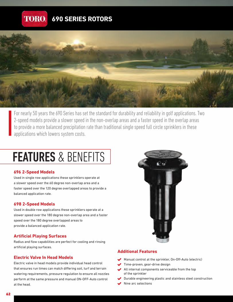
62
For nearly 50 years the 690 Series has set the standard for durability and reliability in golf applications. Two 2-speed models provide a slower speed in the non-overlap areas and a faster speed in the overlap areas to provide a more balanced precipitation rate than traditional single speed full circle sprinklers in these applications which lowers system costs.
696 2-Speed ModelsUsed in single row applications these sprinklers operate at
a slower speed over the 60 degree non-overlap area and a
faster speed over the 120 degree overlapped areas to provide a
balanced application rate.
698 2-Speed ModelsUsed in double row applications these sprinklers operate at a
slower speed over the 180 degree non-overlap area and a faster
speed over the 180 degree overlapped areas to
provide a balanced application rate.
Artificial Playing Surfaces Radius and flow capabilities are perfect for cooling and rinsing
artificial playing surfaces.
Electric Valve In Head ModelsElectric valve in head models provide individual head control
that ensures run times can match differing soil, turf and terrain
watering requirements, pressure regulation to ensure all nozzles
perform at the same pressure and manual ON-OFF-Auto control
at the head.
690 SERIES ROTORS
FEATURES & BENEFITS
Additional Features
Manual control at the sprinkler, On-Off-Auto (electric)
Time-proven, gear-drive design
All internal components serviceable from the top of the sprinkler
Durable engineering plastic and stainless steel construction
Nine arc selections
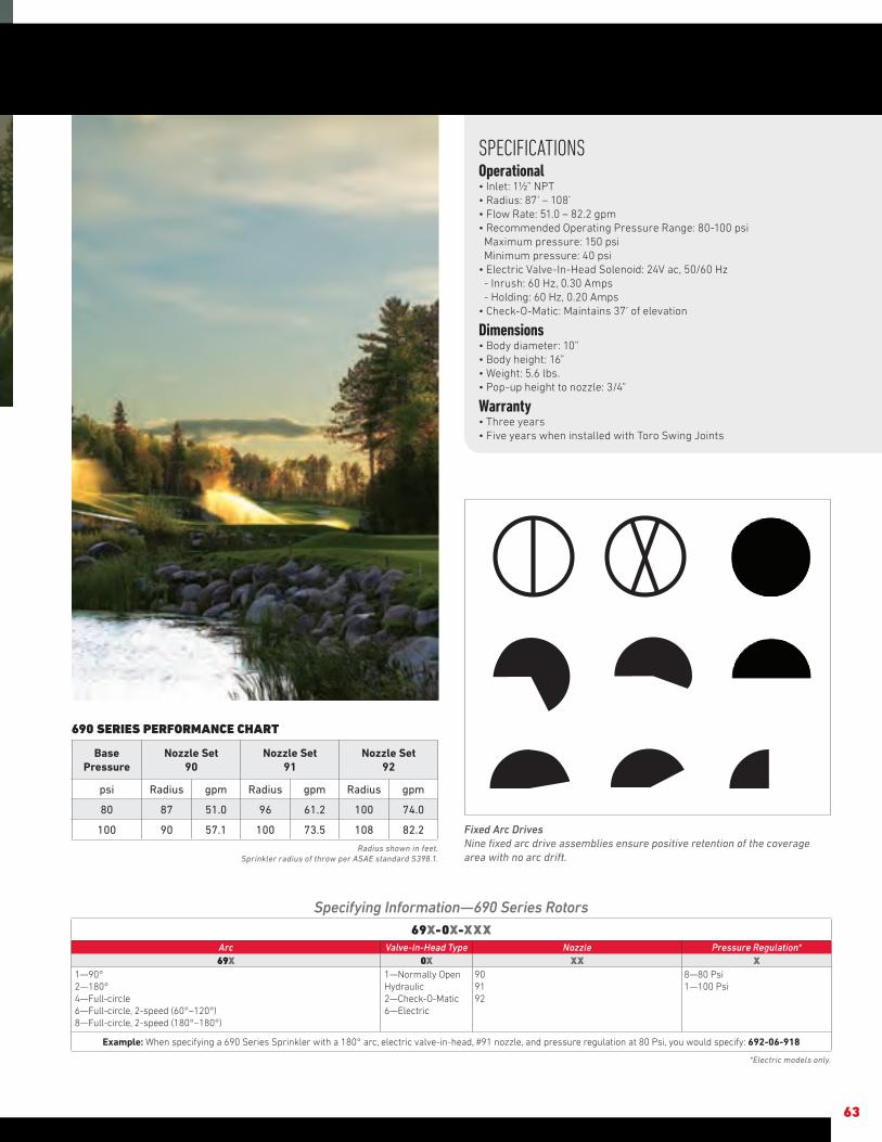
SPECIFICATIONS Operational• Inlet: 1½” NPT• Radius: 87’ – 108’• Flow Rate: 51.0 – 82.2 gpm• Recommended Operating Pressure Range: 80-100 psi Maximum pressure: 150 psi Minimum pressure: 40 psi• Electric Valve-In-Head Solenoid: 24V ac, 50/60 Hz - Inrush: 60 Hz, 0.30 Amps - Holding: 60 Hz, 0.20 Amps• Check-O-Matic: Maintains 37’ of elevation
Dimensions• Body diameter: 10”• Body height: 16” • Weight: 5.6 lbs.• Pop-up height to nozzle: 3/4”
Warranty• Three years• Five years when installed with Toro Swing Joints
63
Specifying Information—690 Series Rotors69X-0X-XXX
Arc Valve-In-Head Type Nozzle Pressure Regulation*69X 0X XX X
1—90° 2—180° 4—Full-circle 6—Full-circle, 2-speed (60°–120°) 8—Full-circle, 2-speed (180°–180°)
1—Normally Open Hydraulic2—Check-O-Matic6—Electric
909192
8—80 Psi1—100 Psi
Example: When specifying a 690 Series Sprinkler with a 180° arc, electric valve-in-head, #91 nozzle, and pressure regulation at 80 Psi, you would specify: 692-06-918
*Electric models only.
Fixed Arc DrivesNine fixed arc drive assemblies ensure positive retention of the coverage area with no arc drift.
690 SERIES PERFORMANCE CHART
BasePressure
Nozzle Set90
Nozzle Set91
Nozzle Set92
psi Radius gpm Radius gpm Radius gpm
80 87 51.0 96 61.2 100 74.0
100 90 57.1 100 73.5 108 82.2
Radius shown in feet.Sprinkler radius of throw per ASAE standard S398.1.

Additional Features
Stainless steel retraction spring
All bodies shipped with flush plug in place
Ratcheting riser feature for arc adjustment
64
Toro’s 590GF Series is the first spray head designed specifically for golf course irrigation with enhanced water management capabilities. The 590GF is built for the tough golf course environment, including harsh debris situations like top-dressing and sand, high water pressures, and daily mower and foot traffic. The 590GF is perfect around bunkers, on small tee boxes, and around the clubhouse. And with its patented X-Flow technology, the 590GF has a built-in shutoff device should a nozzle be damaged or removed and it’s standard check valve feature minimizes low head drainage.
Nozzle OptionsIn addition to the full line of Toro MPR, TVAN and specialty nozzles
the 590GF accepts the revolutionary Precision™ Spray and
Precision™ Rotating Series nozzles with optimized distribution
uniformity that provides exceptional turf conditions with minimal
water usage.
Designed Flush Rate
Sprinkler flushes during pop-up and retraction clearing debris
from around the riser to eliminate stick-ups and ensure positive
sealing and retraction.
X-Flow® Shut Off DeviceThe X-Flow shut off feature stops the flow of water if the nozzle is
damaged or removed to eliminate flooding, water waste and soil
erosion.
Prevent Low Head Drainage The standard check valve prevents low head drainage with up to
10’ of elevation change minimizing soil erosion and water waste.
590GF SERIES SPRAYS
FEATURES & BENEFITS
590GF-4
590GF-6
590GF-12

Without X-Flow®
Water waste, soil erosion and flooding occur
SPECIFICATIONS Operational• Radius: 2’ – 26’• Recommended pressure range: 25-50 psi (maximum – 75 psi)• Flow rate: 0.05 – 4.5 Gpm• 2 Gpm flush rate
Dimensions• Body diameter: - 13/8” on 4P and 6P - 15/8” on 12P • Cap diameter: 2”• Inlet: 1/2” female-threaded
Warranty• Three years
Risers and Extenders 570-6X• Male-inlet threads install onto any 590GF
sprinkler or to provide a 6" extension• Maximum pressure: 75 psi
570SR-6 and 570SR-18 Risers• 1⁄2" male-threaded inlet for installation on
pipe fittings• Maximum pressure: 75 psi• Height: 6" and 18"
65
Flanged Cap Flanged cap installs below grade to stabilize the body position and maintain optimum nozzle performance.
With X-Flow®
Eliminates water waste, soil erosion and flooding
Specifying Information—590GF Series Sprays590GF-XX-E
Model Pop-Up Height Optional590GF XX E
590GF—590GF Series Sprays
4—4” Pop-Up 6—6” Pop-Up 12—12” Pop-Up
E—Effluent

66
Based off the design of the world’s leading gear-driven rotor for golf applications, the Precision™ Series Rotating Nozzle powered by its proven planetary gear drive delivers wind-resistant, multi-stream, multi-trajectory patterns. Both the full circle and adjustable arc models deliver a radius range of 14 to 26 feet with exceptional uniformity and outstanding close-in watering, preventing the need to extend irrigation cycles to compensate for brown spots. The consistent matched precipitation rate of 0.55 inches per hour helps meet the needs of tight water windows.
Gear-DrivenPrecision™ Series Rotating Nozzles utilize a proven planetary gear
drive, variable stator and turbine to rotate the nozzle. The entire
gear package is contained in the area beneath the fine mesh filter
screen. Particles large enough to enter through the filter will exit
out of the nozzle plate through the multi-streams.
Matched Precipitation Rate of 0.55”/hr.These nozzles deliver water more slowly and evenly than
standard spray nozzles.
Consistent Speed of RotationThe gear drive mechanism delivers a consistent speed of rotation
regardless of system pressure and prevents
product stalling at low pressure.
PRECISION™ SERIES ROTATING NOZZLE
FEATURES & BENEFITS
Female-threadedPRN-A
Male-threadedPRN-TA
Female-threadedPRN-F
Male-threadedPRN-TF

SPECIFICATIONS Operational• Radius: 14’-26’• Operating pressure range: 20-75 psi• Recommended Pressure: 40-50 psi• Flow Rate: 0.17-3.68 gpm
Warranty• Five years
67
Step-Up™ Technology Designed to deliver high uniformity with matched precipitation for in-close watering all the way out to the furthest radius point. The unique “steps” create 15 streams, each designed to cover an area of the pattern.
Steps
Steps
Arc psi gpm Radius Precip. Rate n (in./hr.)
Precip. Rate (in./hr.)
45°
20 0.17 14.0 0.67 0.7730 0.19 15.0 0.65 0.7540 0.25 17.0 0.67 0.7750 0.31 18.5 0.70 0.8160 0.35 19.5 0.71 0.8275 0.43 22.0 0.68 0.79
90°
20 0.43 16.0 0.65 0.7530 0.49 17.5 0.62 0.7140 0.62 20.5 0.57 0.6650 0.75 22.5 0.57 0.6660 0.82 23.5 0.57 0.6675 0.92 25.0 0.57 0.65
120°
20 0.48 16.4 0.69 0.7930 0.57 17.5 0.72 0.8340 0.78 20.2 0.55 0.6450 0.97 22.5 0.55 0.6460 1.07 23.5 0.56 0.6575 1.18 25.0 0.55 0.63
180°
20 0.83 15.0 0.71 0.8230 0.94 17.0 0.63 0.7240 1.22 20.5 0.56 0.6550 1.46 22.5 0.56 0.6460 1.61 24.0 0.54 0.6275 1.81 26.0 0.52 0.60
240°
20 1.12 15.0 0.72 0.8330 1.27 17.0 0.63 0.7340 1.56 20.0 0.56 0.6550 1.80 21.5 0.56 0.6560 1.95 22.5 0.56 0.6475 2.20 24.0 0.55 0.64
270°
20 1.08 14.0 0.71 0.8130 1.23 16.0 0.62 0.7140 1.62 19.0 0.57 0.6650 2.00 21.5 0.55 0.6460 2.26 23.0 0.55 0.6375 2.60 25.0 0.53 0.61
360°
20 1.81 15.0 0.77 0.8930 2.00 17.2 0.65 0.7540 2.56 20.9 0.56 0.6550 3.09 22.9 0.57 0.6560 3.34 23.8 0.57 0.6675 3.68 25.6 0.54 0.62
Specifying Information—Precision™ Series Rotating NozzlePRN-XX
Model Thread Model
PRN X XPRN—Precision™ Rotating Nozzle T—Male Thread
Blank—Female ThreadA—Adjustable arcF— Full-circle
Example: A male threaded Precision™ Series Rotating nozzle with a 24’ radius and a 180° arc would be specified as: PRN-TAA female threaded Precision™ Series Rotating nozzle with a 20’ radius and 360° arc would be specified as: PRN-F
Precision™ Series Rotating Nozzle Visual Arc Adjustment The unique adjustment method allows for pre-setting of arc by hand or tool before the nozzle is installed. Visual indicators allow the user to quickly adjust the arc pattern to the desired arc from 45-270°. The adjustment band can be adjusted by hand or with the pre-included tool (PRNTOOL).
180° workingpattern
Right edge
PERFORMANCE DATA –PRECISION™ SERIES ROTATING NOZZLES
Nozzle data subject to change.
Additional Features15 unique streams with different trajectories
Maximum height of 20° trajectory to fight through wind
Threads onto nearly all sprayheads and shrub adapters (male or female)
Pre-attached screen for easy installation
Radius reduction up to 25% by turning set screw
Color coded to identify adjustable or full circle
Precipitation rate = 0.55”/hr. on square spacing plans
Maintains precipitation rate as radius is reduced
Matched precipitation from 14-26 feet
Matched precipitation from 20-75 psi
Adjustable by hand or with included tool
Consistent speed of rotation not affected by pressure

68
Toro’s Precision™ Series Spray Nozzles are the most complete and efficient spray nozzle line available to help irrigation professionals manage water use. The Precision™ Spray nozzles 1”/hr. precipitation rate ensures that water is applied more slowly and evenly. Now also available in pressure-compensating versions, further enhancing the best-in-class spray nozzle in the industry.
Patented H²0 Chip TechnologyUsing patented H²0 chip technology – and no moving parts – each
Precision™ Series Spray nozzle creates one or more high
frequency oscillating streams to achieve the desired arc and
radius with 1/3 less water usage.
Maximize Irrigation EfficiencyPrecision™ Spray nozzles deliver an industry first 1”/hr
precipitation rate, which better matches soil infiltration rate. This
lower precipitation rate, along with high distribution uniformity
make this nozzles family the most efficient nozzle from 5’-15’.
Pressure-Compensating Versions AvailablePressure-Compensating Precision™ Series Spray Nozzles
maintain 1”/hr precipitation rate and minimizes misting up to
inlet pressures to more than 40 Psi, minimizing the need for a
regulating head, at fraction of the cost.
PRECISION™ SERIES SPRAY NOZZLE
FEATURES & BENEFITS
No Moving or Sonic Welded PartsAssures no variation at the end of the water arc for better edge definition and consistent, reliable performance.

SPECIFICATIONS Operational• Radius: 5’-15’ (1,5-4,6m)• Operating pressure range: 20-75 psi (1,4-5,2 Bar)• Recommended Pressure: non-Pressure-Compensating—30 psi (2,1
Bars), Pressure Compensating—50 psi (3,4 Bars)• Flow Rate: 0.04-2.4 gpm (0,1-9,4 LPM)• Nozzle trajectory: - 5’: 5° - 8’: 10° - 10’: 15° - 12’: 20° - 15’: 27° - Corner and Side Strips: 20°
Warranty• Two years
69
H20 Technology Water expands and collapses inside the H²0 Chip creating high-frequency oscillating streams which allow for distance of throw using 1/3 less flow.
Pressure Compensation DeviceThe elastomeric PCD disk opens and closes in response to changes in inlet pressure to maintain optimal performance, even when the pressure rises higher than 40 Psi.
Competitor’s High Flow Nozzle:12H Nozzle at 50 Psi = 1.83Gpm or 2.45”/hr.*
Precision™ Series Spray Nozzle with PCD Nozzle: 12H Nozzle at 50 Psi = 0.74 Gpm or 1”/hr.*
*Based on internal flow rate test data in Riverside, CA.
Up To60% Less
Water!
Precision™ Series Spray Nozzle with PCD Performs Under Pressure!
Specifying InformationO-X-XXXX-XXXX
Nozzle Thread Radius Arc Body
O X XXXX XXXX
O—1” Per Hour T—Toro Male Threaded NozzleBlank—Female Threaded Nozzle
5—5’ 8—8’ 10—10’ 12— 12’ 15—15’
(4X15—4’X15’* 4X30—4’X30’*
4X9—4’X9’ 4X18—4’X18’
60—60° Q—90° T—120° 150—150° H—180° 210—210°
TT—240° TQ—270°F-360—Full-circle LCS—Left CornerRCS—Right Corner SST—Side Strip*
P— Pressure-Compensating
Call out body as required
Example: A female threaded Precision™ Series Spray with a spray radius of 12’ (3,7m) and a 90° arc would be specified as: O-12-QExample 2: A male threaded Pressure-Compensating Precision™ Series Spray with a spray radius of 10’ (3,0m) and a 180° arc would be spcified as O-T-10-HP
Additional FeaturesSpecialty Arcs available (60°*, 120°, 150°*, 210°, 240°)
Radius reduction 25% maximum
Color coded for radius on top of the nozzle
Precipitation rate ≤ 1”/hour
Maintains precipitation rate as radius is reduced up to max of 25%
Matched precipitation rate within radius families
Matched precipitation rates between radius families
Screen attached to nozzle for easy insertion into the spray body
Works on all spray bodies-male and female

PRECISION™ SERIES SPRAY NOZZLE PERFORMANCE CHARTS
9 Arcs Plus Side and Corner Strips Available
4’ X 15’4’ X 9’
60°* 90° 120° 150°* 180° 210°* 240° 270° 360°
* Not available with Pressure-Compensation
5 Radii Available inMale & Female Threads
5’8’
10’12’
15’
LCS (Left Corner Strip)
SST (Side Strip)
RCS (Right Corner Strip)
4’ X 15’4’ X 9’
4’ X 30’4’ X 18’
PERFORMANCE DATA PRESSURE-COMPENSATING PRECISION™ SERIES SPRAY NOZZLES
Arc psi gpm RadiusPrecip. Rate S (in./hr.)
Precip. Rate (in./hr.)
5Q40 0.06 4.6 1.0 1.250 0.08 5.1 1.2 1.460 0.09 5.6 1.3 1.570 0.11 6.2 1.5 1.7
5T40 0.07 4.4 1.0 1.150 0.11 4.9 1.3 1.560 0.15 5.5 1.7 2.070 0.19 6.0 2.0 2.4
5H40 0.10 4.4 1.0 1.250 0.13 4.9 1.1 1.360 0.16 5.4 1.3 1.570 0.19 6.0 1.4 1.6
5TT40 0.14 4.3 1.1 1.350 0.20 4.9 1.3 1.560 0.25 5.4 1.4 1.770 0.31 6.0 1.6 1.8
5TQ 40 0.15 4.3 1.0 1.250 0.21 4.9 1.2 1.460 0.26 5.6 1.4 1.670 0.32 6.2 1.5 1.7
5F 40 0.17 4.0 1.0 1.250 0.24 4.8 1.1 1.360 0.31 5.5 1.2 1.470 0.38 6.3 1.3 1.5
Arc psi gpm RadiusPrecip. Rate S (in./hr.)
Precip. Rate (in./hr.)
8Q40 0.14 7.0 1.1 1.3
50 0.17 7.7 1.2 1.3
60 0.20 8.4 1.2 1.4
70 0.23 9.1 1.3 1.4
8T40 0.20 7.6 1.0 1.2
50 0.24 8.0 1.1 1.3
60 0.27 8.5 1.2 1.4
70 0.31 8.9 1.3 1.5
8H40 0.26 7.0 1.0 1.2
50 0.33 7.6 1.1 1.3
60 0.39 8.1 1.2 1.4
70 0.46 8.7 1.3 1.4
8TT40 0.34 7.0 1.0 1.1
50 0.43 7.8 1.1 1.2
60 0.52 8.5 1.2 1.4
70 0.61 9.3 1.3 1.5
8TQ40 0.41 7.2 1.0 1.1
50 0.48 7.9 1.1 1.2
60 0.55 8.6 1.1 1.3
70 0.62 9.3 1.2 1.4
8F40 0.55 7.0 1.1 1.2
50 0.65 7.5 1.1 1.2
60 0.74 8.0 1.1 1.3
70 0.84 8.5 1.1 1.3
Arc psi gpm RadiusPrecip. Rate S (in./hr.)
Precip. Rate (in./hr.)
10Q40 0.26 9.5 1.0 1.1
50 0.28 10.0 1.1 1.2
60 0.29 10.5 1.1 1.3
70 0.31 11.1 1.2 1.4
10T40 0.31 9.5 1.0 1.1
50 0.36 10.0 1.1 1.2
60 0.41 10.5 1.2 1.4
70 0.46 11.0 1.3 1.5
10H40 0.48 9.7 1.0 1.1
50 0.53 10.1 1.1 1.2
60 0.57 10.4 1.1 1.3
70 0.62 10.8 1.2 1.4
10TT40 0.63 9.6 1.0 1.1
50 0.70 9.9 1.1 1.2
60 0.77 10.3 1.1 1.3
70 0.84 10.6 1.2 1.4
10TQ40 0.71 9.5 1.0 1.1
50 0.77 9.9 1.0 1.2
60 0.82 10.3 1.1 1.2
70 0.88 10.7 1.1 1.3
10F40 0.95 9.6 1.0 1.1
50 1.06 10.0 1.1 1.2
60 1.16 10.5 1.1 1.3
70 1.27 10.9 1.2 1.4
Arc psi gpm RadiusPrecip. Rate S (in./hr.)
Precip. Rate (in./hr.)
12Q40 0.34 12.0 1.0 1.2
50 0.39 12.2 1.1 1.3
60 0.43 12.5 1.2 1.3
70 0.48 12.7 1.2 1.4
12T40 0.46 11.5 1.0 1.2
50 0.50 11.8 1.0 1.2
60 0.54 12.0 1.1 1.3
70 0.58 12.3 1.1 1.3
12H40 0.70 11.5 1.0 1.2
50 0.75 11.8 1.0 1.2
60 0.80 12.2 1.1 1.2
70 0.85 12.5 1.1 1.2
12TT40 0.90 11.4 1.0 1.2
50 1.03 11.5 1.1 1.3
60 1.16 11.5 1.2 1.3
70 1.29 11.6 1.2 1.4
12TQ40 1.05 11.4 1.0 1.2
50 1.14 11.7 1.0 1.2
60 1.23 12.0 1.1 1.3
70 1.32 12.3 1.1 1.3
12F40 1.35 11.5 1.0 1.1
50 1.49 11.8 1.0 1.2
60 1.63 12.2 1.1 1.3
70 1.77 12.5 1.1 1.3
Arc psi gpm RadiusPrecip. Rate S (in./hr.)
Precip. Rate (in./hr.)
15Q40 0.53 14.2 1.0 1.2
50 0.59 14.5 1.1 1.2
60 0.64 14.8 1.1 1.3
70 0.70 15.1 1.2 1.3
15T40 0.72 14.3 1.0 1.2
50 0.77 14.8 1.0 1.2
60 0.82 15.2 1.1 1.2
70 0.87 15.7 1.1 1.2
15H40 1.10 14.5 1.0 1.2
50 1.20 14.3 1.1 1.2
60 1.29 14.0 1.1 1.3
70 1.39 13.8 1.2 1.3
15TT40 1.45 14.5 1.0 1.2
50 1.57 14.8 1.0 1.2
60 1.68 15.0 1.1 1.2
70 1.80 15.3 1.1 1.3
15TQ40 1.60 14.0 0.9 1.0
50 1.70 14.4 1.0 1.1
60 1.80 14.8 1.0 1.2
70 1.90 15.1 1.1 1.2
15F40 2.20 14.5 1.0 1.2
50 2.36 14.8 1.0 1.2
60 2.52 15.1 1.1 1.2
70 2.68 15.4 1.1 1.3
Arc psi gpm RadiusPrecip. Rate S (in./hr.)
Precip. Rate (in./hr.)
4X30SST
40 0.62 4x30 1.0 1.1
50 0.65 4x30 1.0 1.2
60 0.67 4x30 1.1 1.3
70 0.70 4x30 1.1 1.3
4X15LCS
40 0.32 4x15 1.0 1.2
50 0.33 4x15 1.1 1.2
60 0.34 4x15 1.1 1.3
70 0.35 4x15 1.2 1.3
4X15RCS
40 0.32 4x15 1.0 1.2
50 0.33 4x15 1.1 1.2
60 0.34 4x15 1.1 1.3
70 0.35 4x15 1.2 1.3
4X18SST
40 0.36 4X18 1.0 1.1
50 0.37 4X18 1.0 1.2
60 0.38 4X18 1.0 1.2
70 0.39 4X18 1.0 1.2
4X9LCS
40 0.18 4X9 1.0 1.1
50 0.19 4X9 1.1 1.2
60 0.20 4X9 1.1 1.2
70 0.21 4X9 1.2 1.3
4X9RCS
40 0.18 4X9 1.0 1.2
50 0.19 4X9 1.1 1.2
60 0.20 4X9 1.1 1.2
70 0.21 4X9 1.2 1.3
70 | Learn more at www.toro.com/golf

71
Arc psi gpm RadiusPrecip. Rate S (in./hr.)
Precip. Rate (in./hr.)
5-60°20 0.04 4.7 1.0 1.1530 0.04 5.0 1.0 1.1540 0.04 5.0 1.0 1.1550 0.05 5.3 1.0 1.14
5Q20 0.06 4.6 1.0 1.1830 0.06 5.0 1.0 1.1440 0.07 5.0 1.0 1.1650 0.07 5.0 1.0 1.17
5T20 0.07 4.4 1.0 1.1730 0.09 5.0 1.0 1.2040 0.09 5.2 1.0 1.1550 0.10 5.4 1.0 1.13
5-150°20 0.07 4.0 1.0 1.1830 0.11 5.0 1.0 1.1940 0.12 5.2 1.0 1.2050 0.13 5.4 1.0 1.20
5H20 0.10 4.4 1.0 1.1530 0.13 5.0 1.0 1.1640 0.14 5.1 1.0 1.1550 0.14 5.2 1.0 1.14
5-210°20 0.10 4.4 1.0 1.1530 0.15 5.2 1.1 1.2340 0.16 5.3 1.1 1.2750 0.17 5.5 1.1 1.25
5TT 20 0.14 4.3 1.1 1.2630 0.17 5.0 1.0 1.1340 0.19 5.0 1.1 1.2350 0.19 5.0 1.1 1.25
5TQ 20 0.15 4.3 1.0 1.1730 0.20 5.0 1.0 1.1640 0.21 5.0 1.1 1.2150 0.22 5.0 1.1 1.27
5F 20 0.17 4.0 1.0 1.1830 0.26 5.0 1.0 1.1640 0.26 5.0 1.0 1.1650 0.26 5.0 1.0 1.16
Arc psi gpm RadiusPrecip. Rate S (in./hr.)
Precip. Rate (in./hr.)
8-60°20 0.10 7.6 1.0 1.230 0.11 8.0 1.0 1.140 0.12 8.1 1.1 1.250 0.13 8.3 1.1 1.3
8Q20 0.14 7.0 1.1 1.330 0.17 8.0 1.0 1.140 0.18 8.2 1.0 1.250 0.18 8.4 1.0 1.1
8T20 0.20 7.6 1.0 1.230 0.22 8.0 1.0 1.140 0.23 8.2 1.0 1.150 0.24 8.3 1.0 1.1
8-150°20 0.25 7.5 1.0 1.230 0.27 8.0 1.0 1.140 0.28 8.1 1.0 1.150 0.29 8.2 1.0 1.2
8H20 0.26 7.0 1.0 1.230 0.33 8.0 1.0 1.140 0.34 8.0 1.0 1.250 0.34 8.0 1.0 1.2
8-210°20 0.33 7.6 1.1 1.330 0.36 8.0 1.1 1.340 0.37 8.1 1.1 1.350 0.38 8.2 1.1 1.3
8TT 20 0.34 7.0 1.0 1.230 0.44 8.0 1.0 1.140 0.46 8.0 1.0 1.250 0.46 8.0 1.0 1.2
8TQ 20 0.41 7.2 1.0 1.130 0.49 8.0 1.1 1.140 0.54 8.0 1.1 1.250 0.55 8.0 1.1 1.2
8F 20 0.55 7.0 1.1 1.230 0.66 8.0 1.0 1.140 0.68 8.0 1.0 1.250 0.71 8.0 1.1 1.2
Arc psi gpm RadiusPrecip. Rate S (in./hr.)
Precip. Rate (in./hr.)
10-60°20 0.16 9.5 1.0 1.230 0.17 10.0 1.0 1.140 0.18 10.0 1.0 1.250 0.19 10.0 1.1 1.3
10Q20 0.26 9.5 1.0 1.130 0.23 10.0 1.0 1.240 0.28 10.2 1.0 1.250 0.28 10.3 1.0 1.2
10T20 0.31 9.5 1.0 1.130 0.34 10.0 1.0 1.140 0.36 10.0 1.0 1.250 0.37 10.0 1.1 1.2
10-150°
20 0.41 9.8 1.0 1.130 0.43 10.0 1.0 1.140 0.44 10.2 1.0 1.150 0.46 10.4 1.0 1.1
10H20 0.48 9.7 1.0 1.130 0.51 10.0 1.0 1.140 0.55 10.3 1.0 1.250 0.56 10.4 1.0 1.2
10-210°
20 0.56 9.8 1.1 1.330 0.58 10.0 1.1 1.340 0.60 10.4 1.1 1.250 0.62 10.5 1.1 1.3
10TT 20 0.63 9.6 1.0 1.130 0.69 10.0 1.0 1.240 0.73 10.3 1.0 1.150 0.74 10.4 1.0 1.1
10TQ 20 0.71 9.5 1.0 1.130 0.79 10.0 1.0 1.140 0.84 10.3 1.0 1.150 0.86 10.4 1.0 1.1
10F 20 0.95 9.6 1.0 1.130 1.03 10.0 1.0 1.140 1.08 10.3 1.0 1.150 1.12 10.4 1.0 1.2
Arc psi gpm RadiusPrecip. Rate S (in./hr.)
Precip. Rate (in./hr.)
12-60°20 0.24 11.5 1.0 1.230 0.25 12.0 1.0 1.240 0.26 12.1 1.0 1.250 0.28 12.2 1.1 1.3
12Q20 0.34 12.0 1.0 1.230 0.37 12.1 1.0 1.140 0.39 11.4 1.0 1.250 0.39 12.0 1.0 1.1
12T20 0.46 11.5 1.0 1.230 0.49 12.0 1.0 1.140 0.51 12.2 1.0 1.150 0.52 12.3 1.0 1.1
12-150°
20 0.60 11.6 1.0 1.230 0.62 12.0 1.0 1.240 0.63 12.2 1.0 1.150 0.64 12.3 1.0 1.1
12H20 0.70 11.5 1.0 1.230 0.74 12.0 1.0 1.140 0.79 12.3 1.0 1.250 0.80 12.4 1.0 1.2
12-210°
20 0.76 11.6 1.1 1.330 0.82 12.0 1.1 1.340 0.84 12.3 1.1 1.250 0.85 12.4 1.1 1.2
12TT 20 0.90 11.4 1.0 1.230 0.99 12.0 1.0 1.140 1.04 12.3 1.0 1.150 1.05 12.4 1.0 1.1
12TQ 20 1.05 11.4 1.0 1.230 1.15 12.0 1.0 1.240 1.19 12.2 1.0 1.250 1.22 12.3 1.0 1.2
12F 20 1.35 11.5 1.0 1.130 1.48 12.0 1.0 1.140 1.59 12.4 1.0 1.150 1.60 12.5 1.0 1.1
Arc psi gpm RadiusPrecip. Rate S (in./hr.)
Precip. Rate (in./hr.)
15-60°20 0.35 14.0 1.0 1.230 0.39 15.0 1.0 1.240 0.40 15.1 1.0 1.250 0.42 15.3 1.0 1.2
15Q20 0.53 14.2 1.0 1.230 0.58 15.0 1.0 1.140 0.60 15.1 1.0 1.250 0.61 15.3 1.0 1.2
15T20 0.72 14.3 1.0 1.230 0.77 15.0 1.0 1.140 0.81 15.3 1.0 1.250 0.82 15.4 1.0 1.2
15-150°
20 0.92 14.7 1.0 1.230 0.96 15.0 1.0 1.240 1.00 15.2 1.0 1.250 1.10 15.3 1.1 1.3
15H20 1.10 14.5 1.0 1.230 1.16 15.0 1.0 1.140 1.25 15.4 1.0 1.250 1.28 15.5 1.0 1.2
15-210°
20 1.15 14.5 1.1 1.230 1.20 15.0 1.0 1.240 1.30 15.5 1.0 1.250 1.40 15.6 1.1 1.3
15TT 20 1.45 14.5 1.0 1.230 1.54 15.0 1.0 1.140 1.58 15.2 1.0 1.150 1.61 15.3 1.0 1.1
15TQ 20 1.72 14.5 1.0 1.230 1.78 15.0 1.0 1.140 1.82 15.0 1.0 1.250 1.90 15.3 1.0 1.2
15F 20 2.20 14.5 1.0 1.230 2.31 15.0 1.0 1.140 2.35 15.2 1.0 1.150 2.40 15.3 1.0 1.1
Arc psi gpm RadiusPrecip. Rate S (in./hr.)
Precip. Rate (in./hr.)
4X30SST
20 0.62 4x28 1.0 1.130 0.66 4x30 1.1 1.240 0.67 4x30 1.1 1.250 0.68 4x30 1.1 1.3
4X15LCS
20 0.32 4x15 1.0 1.230 0.33 4x15 1.1 1.240 0.34 4x15 1.1 1.350 0.34 4x15 1.1 1.3
4X15RCS
20 0.32 4x15 1.0 1.230 0.33 4x15 1.1 1.240 0.34 4x15 1.1 1.350 0.34 4x15 1.1 1.3
4X18SST
20 0.36 4X18 1.0 1.130 0.37 4X18 1.0 1.140 0.38 4X18 1.0 1.250 0.38 4X18 1.0 1.2
4X9LCS
20 0.18 4X9 1.0 1.130 0.19 4X9 1.0 1.240 0.20 4X9 1.1 1.250 0.20 4X9 1.1 1.1
4X9RCS
20 0.18 4X9 1.0 1.230 0.19 4X9 1.0 1.240 0.20 4X9 1.1 1.250 0.20 4X9 1.1 1.2
PERFORMANCE DATA PRECISION™ SERIES SPRAY NOZZLES

72
Subsurface irrigation provides water directly to the root zone to ensure maximum utilization, minimizing the waste from evaporation and surface runoff. These kits provide everything you need to set up a tee box, bunker system, lake perimeter or anywhere else a low volume subsurface system applies.
Pressure Compensating EmittersEvery emitter is equipped with a pressure compensating device
to ensure the optimum operating pressure and precise flow rates
are distributed from each point throughout the zone regardless of
distance or elevation change.
Treflan® Root InhibitorEach emitter is impregnated with Treflan, a powerful root inhibitor
than prevents roots from entering and clogging the emitter
opening. This ensures even water distribution uniformity and
maximum efficiency from each point of emission.
Filtration and Pressure Regulation ProvidedEach kit includes a Y filter with 150 mesh/100 micron element
to prevent debris contamination and a 25 psi fixed regulator to
eliminate damage from high pressure spikes.
Flush ValveProvides a momentary high velocity in the tubing to move debris
out of the piping system to eliminate emitter clogging every time
the zone is activated.
SUBSURFACE IRRIGATION
FEATURES & BENEFITS
Air Relief Valve Opens at the end of every watering cycle allowing clean air to enter the system and eliminate emitter clogging from siphoning.

SPECIFICATIONS Drip System Specifications-Bunkers Only• Flow range: - Low flow: 0.1 to 8.0 gpm - High flow: 2.0 to 20.0 gpm• DL2000™ range: - Low flow: 12’ to 1000’ - High flow: 250’ to 2500’• Pressure compensating emitter: 0.5 gph • Emitter spacing – 12"• DL2000™ maximum run length: 250’• Application rate (12” x 12” spacing): 0.85” per hour
Benefits On Bunkers• Uniformly applies water to areas such as fingers• Minimizes runoff• Eliminates overspray into bunker keeping sand dry• Cycle/soak allows for application on steep slopes• Reduces bunker cave-ins• Saves time, labor and money by eliminating the need for
hand-watering
Benefits On Tees• Applies water directly to the root zone allowing turf to stay dry• Water is applied precisely to the tee box without watering the
surrounding area
Bunker System Components• DL2000™ subsurface dripline• Drip Zone Valve Kit – includes control valve, pressure
regulator, Y-filter and manual ball valve• Air Vent Assembly – pre-assembled and ready to install
(bunker only)• Required inlet/outlet fittings• Flush Assembly Fittings (8 gpm) 2 psi sealing flush valve
(bunker only)• Installation Fittings: - Includes Loc-Eze® tees, couplings, elbows and end clamps - 10’ of Blue Stripe® polyethylene tubing - Soil staples for secure tubing placement• Pipe thread tap
Warranty• Two years
73
Specifying Information—Subsurface IrrigationModel Number Description
SSDS-LF-500SSDS-HF-1000RGP-212-05
DL2000 500' Drip System (Bunker)—Low FlowDL2000 1000' Drip System (Bunker)—High FlowDL2000 500’ (Roll, 0.5 GPH), 12” Spacing
Example: A 500' DL2000 Drip System, would be specified as: SSDS-LF-500

74
Toro offers a full line of swing joints that cover all Golf sprinkler thread types. Swing joints provide the flexibility to align the sprinkler to proper grade and level positioning to ensure optimum water use through maximum nozzle distribution uniformity.
Minimize Friction Loss1”, 1¼” and 1½” models are available to cover flows exceeding 80
Gpm, and minimize friction loss to ensure optimum pressure is
available at each sprinkler.
Standard 2X90 And Ultra 4X90 Outlet Configurations
The standard 2x90 models provide two 90’s at the outlet for
alignment in two directions and the Ultra 4x90 models provide
four 90’s at the outlet for maximum alignment flexibility in four
directions.
Saddle And Glue Tee Models Glue tees for PVC piping applications and saddle tees for HDPE
and PVC piping applications. Both tee styles are available with 1”,
1¼” and 1½” double o-ring sealing outlets.
Quick Coupler Models
All swing joint styles are available with a quick coupler outlet
that includes both an anti-rotation and position stabilizing feature
to ensure the quick coupling valve stays secure during key
installation and removal.
SWING JOINTS
FEATURES & BENEFITS
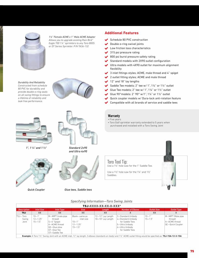
Additional Features
Schedule 80 PVC construction
Double o-ring swivel joints
Low friction loss characteristics
315 psi pressure rating
800 psi burst pressure safety rating
Standard models with 2X90 outlet configuration
Ultra models with 4X90 outlet for maximum alignment flexibility
3 inlet fittings styles; ACME, male thread and 4” spigot
2 outlet fitting styles; ACME and male thread
12” and 18” lay lengths
Saddle Tee models; 2” tee w/ 1”, 1¼” or 1½” outlet
Glue Tee models; 2” tee w/ 1”, 1¼” or 1½” outlet
Glue 90°models: 2” 90° w/1”, 1¼” or 1½” outlet
Quick coupler models w/ Dura-lock anti-rotation feature
Compatible with all brands of service and saddle tees
Warranty• Five years• Toro Golf sprinkler warranty extended to 5 years when
purchased and installed with a Toro Swing Joint
Toro Tool Tip: Use a 1¼” hole saw for the 1” Saddle Tee.
Use a 1½” hole saw for the 1¼” and 1½” Saddles.
75
Durability And ReliabilityConstructed from schedule 80 PVC for durability and provide double o-ring seals on all swing fittings to ensure a lifetime of reliability and leak free performance.
1¼” Female ACME x 1” Male ACME AdapterAllows you to upgrade existing Rain Bird®* Eagle 700 1¼” sprinklers to any Toro 800S or DT Series Sprinkler. P/N TA36-132
Specifying Information—Toro Swing JointsTSJ-XXXX-XX-XX-X-XXX*
Description Inlet Size Inlet Type Size Length Number of Elbows Outlet Size Outlet TypeTSJ XX XX XX XX X XX X
TSJ— Toro Swing Joint
10—1”12—1.25”15—1.5”
M—MIPT (male pipe thread)S—4” SpigotA—ACME threadGE—Glue elowGT—Glue TeeST—Saddle Tee
Blank—same as inlet size10—1”12—1.25”15—1.5”
12—12” Lay Length18—18” Lay Length
3—Standard Unibody4—Standard Unibody for Saddle Tees5—Ultra Unibody6—Ultra Unibody for Saddle Tees
10—1” 15—1.5”
M—MIPT (Male pipe thread)A—ACME threadQC—Quick Coupler
Example: A Toro 1½” Swing Joint with an ACME inlet, 12” lay length, 3 elbows (standard uni-body) and 1½” ACME outlet fitting would be specified as: TSJ-15A-12-3-15A
1", 1 1/4" and 1 1/2" Standard 2x90 and Ultra 4x90
Glue tees, Saddle teesQuick Coupler

76
995-15 Selector tool• All electric golf sprinklers • Allows user to manually turn the
sprinkler “ON”, turn or leave it “OFF” or place it into the “AUTO” position awaiting a command from the controller
995-83 Multi Purpose tool• All Golf sprinklers • Riser pull up for INFINITY, FLEX800, DT
and 800S Series• Riser screen removal on all models• Upper snap ring remover on all models
PNOZZTOOLRiser Pull Up Tool • Used on 590GF sprays
Riser Removal Tools• 995-06 drive assembly extraction tool
630, 650 and 690 models - Threads into the nozzle base and allows
removal of the drive from the body• 995-85 drive assembly extraction tool
730,750,760,780,860S,880S - Threads onto the drive output shaft and allows removal of the drive from the body
995-82 Arc adjustment tool, 3/32” Allen Wrench• 765,785,865S,885S Arc adjustment of the
part circle drives• INFINITY, FLEX800, DT and 800S Series.
Adjustment of the radius reduction screw
Valve Removal Tools • 995-08 All 1” golf models and 640 • 995-09 All 1.5” models and 690
Nut Drivers• 995-105 5/16” INFINITY, FLEX800, DT
and 800S Series TruJectory adjustment on INFX5-6/FLX5-6 models
- Inner, intermediate and back nozzle removal on all DT and 800S models
• 995-99 5/8” - Series Dual trajectory selection - Main nozzle removal on all models• 995-79 7/16” 834S/854S pre August 2007 - Inner, intermediate and back nozzle removal - 650/760/780/860S/880S Inner,
intermediate and back nozzle removal• 995-81 9/16” 760/780 Series Main nozzle removal• 995-80 1/2” 760/780/860S/880S Nozzle base jam nut removal• 995-52 1/4” 660/680 Drive plate nut
removal• 995-53 3/8” 660/680 Cap nut removal
Valve Insertion ToolsAligns and Installs Valve into the Body• 995-xx 640 VIH body• 995-76 All 1” golf models • 995-101 All 1.5” golf models • 995-12 690 body• 995-20 690 with rubber cover • 118-1843 INFINITY 50 models• 118-1844 INFINITY 30 models
995-100 Valve Snap Ring Pliers with Screen Remover• All Golf sprinklers Lower snap ring removal on all models• Rock screen removal on all INFINITY,
FLEX800, DT and 800S Series• Valve removal on all models
Riser Hold Up Tools Allow for Nozzle Servicing• 118-0954 Riser hold up tool, red• 995-55 All 700 models • 995-102 Universal hold up tool, all 700, 800S, DT, INFINITY and FLEX800 models
76
GOLF SPRINKLERS SPRINKLER TOOLS

77
Valve Comparison Chart
Model 220G Brass Series
P220GSeries
P220GS SeriesScrubber
Catalog Pages 78-79 80-81 80-81
Flow Range 5.0-180 gpm 5.0-300 gpm 5.0-180 gpm
Operating Pressure 10-220 psi max 10-220 psi max 10-220 psi max
Conditions
Electrically Activated Systems X X X
Pressure Regulated Systems X X X
Effluent Water X X X
Sizes
1” X X X
11/4” X
11/2” X X X
2” X X X
ConfigurationsInline/Globe X X X
Angle/Globe X X
Inlet/Outlet Threaded (Female) X X X
Features
Manual Flow Control X X X
Pressure Regulation X X X
Internal Manual Bleed X X X
External Manual Bleed (Flush) X X X
Body ConstructionGlass-filled Nylon X X
Brass X
Warranty 5 Years 5 Years 5 Years
77
VALVES AND VALVE BOXES COMPARISON CHARTS

78
The 220G Brass Series valves provide extra durability in the most challenging environments on the course. With precise pressure regulation the optimum operating pressure and exact flow requirements are delivered to every sprinkler ensuring maximum efficiency and uniformity.
EZReg® Pressure Regulating SystemCan be adjusted from 5-100 Psi to provide the optimum operating
pressure for every zone.
Spike Guard™ Solenoid
With 20,000 volt lightning rating, it virtually eliminates the
need for solenoid replacements. And with half the amperage
draw of traditional solenoids you can run twice as many valves
simultaneously, reduce the cost of wire during installation or
increase the distance from controller to valve.
Internal Manual BleedEnsures the optimum pressure of the system even when being
operated manually.
Self Flushing And Serviceable Filter A 120 mesh stainless steel screen in the flow of water is
continually being cleaned any time the valve is in operation.
Serviceable from the side of the valve the filter can be removed
without valve disassembly.
220G BRASS SERIES VALVES
FEATURES & BENEFITS
220G-27-04
220G-27-06

SPECIFICATIONS Operational• Flow Range: – 1” – 5 to 40 gpm – 1¼” – 20 to 100 gpm – 1½” – 20 to 130 gpm – 2” – 30 to 180 gpm• Operating Pressure (220 psi maximum pressure rating): – Electric – 10 to 220 psi• Pressure regulating: – Outlet: 5 to 100 psi ± 3 psi• Inlet: 10 to 220 psi• Minimum pressure differential (between inlet and outlet) for pressure
regulation: 10 psi (2" is 20 psi)• Burst pressure safety rating: 750 psi• Body style: – Globe valve – 1”, 1¼”, 1½”, 2” female threads• Spike Guard™ Solenoid: 24 VAC (50/60 Hz) Standard – Inrush: 60 Hz: 0.12 amps – Holding: 60 Hz: 0.1 amps• DC latching – momentary low voltage pulse
Dimensions• 1” – 5¼” H x 5” W• 1¼” – 6½” H x 6” W• 1½” - 6½” H x 6” W• 2” – 7½” H x 7” W
79
Fabric Reinforced DiaphragmProvides superior performance and extended life without tearing in high pressure applications.
Specifying Information—220G Brass Series220G-27-0XXX
Type Body Style Size Optional
220G 27 OX XX
220G—220G Brass Series Valve 27—NPT, Pressure-regulated (5–100 Psi) 4—1" 5—11⁄4" 6—11⁄2" 8—2"
DL—Latching Solenoid for 2-wire GDC SystemsE—Effluent
Example: A 1" NPT pressure-regulated, 220G Brass Series Valve with 60 Hz solenoid, would be specified as: 220G-27-04
220G BRASS SERIES FRICTION LOSS DATA
Model TypeGpm Flow
5 10 15 20 30 40 50 60 70 80 100 120 150 170 180
1" Electric 1.75 2.0 2.2 3.10 5.05 7.80
11/4" Electric 1.85 2.50 2.70 3.50 4.10 5.6
11/2" Electric 2.15 2.45 2.80 3.05 3.80 5.0 6.55
2" Electric 3.05 3.20 2.90 2.95 3.25 3.40 4.50 6.55 10.10 13.45 14.85
Notes: For optimum performance when designing a system, calculate total friction loss to ensure sufficient downstream pressure.For optimum regulation performance, size regulating valves toward the higher flow ranges.
Flow rates are recommended not to exceed 5 psi loss.
VALVE WIRE SIZING CHARTMaximum One-way Distance (in ft.) Between Controller
and Valve Using Spike-Guard™ Solenoid*
Ground WireControl Wire
18 16 14 12 10 8 6
18 2040 2520 2940 3280 3540 3720 3860
16 2520 3260 4000 4660 5220 5620 5920
14 2940 4000 5180 6360 7420 8300 8960
12 3280 4660 6360 8240 10100 11800 13180
10 3540 5220 7420 10100 13180 16060 18770
8 3720 5260 8300 11800 16060 20800 25540
6 3860 5960 8960 13180 18700 25540 33080
* Solenoid Model: 24 V ac Pressure: 150 Psi Voltage Drop: 4 V Minimum Operating Voltage: 20 V Amperage (peak) 0.12 A
Additional FeaturesDiaphragm stem guide
Ingot brass and stainless steel construction
Pressure regulates in electric and manual modes, serviceable under pressure
Forward-flow design for more precise regulation
Standard, built-in Schrader-type valve for downstream pressure verification
Anti-vandal dust cap on pressure-regulating models
No external tubing
External manual bleed for system flushing
Manual flow control: adjustable to zero flow
– Stainless steel diaphragm support ring for minimum wear
– Stainless steel solenoid seat for longer life and positive shutoff
– Low-power requirement for longer wire runsWarranty• Five years

80
The P220G and P220GS Series provide a full family of plastic valves that can deliver the water to meet the challenging needs of today’s courses. With precise pressure regulation these valves deliver the optimum pressure and flow requirements to every sprinkler on the zone ensuring maximum uniformity of the water to the turf.
EZReg® Pressure Regulating SystemCan be adjusted from 5-100 Psi to deliver the optimum pressure
for every need.
Spike Guard™ Solenoid
With its 20,000 volt lightning rating, it virtually eliminates the need
for solenoid replacements in high lightning environments.
Internal Manual BleedEnsures the optimum pressure of the system even when being
operated manually.
Double-beaded Fabric Reinforced DiaphragmProvides superior performance and extended life without tearing
in high-pressure golf applications.
P220G AND P220GS SERIES VALVES
FEATURES & BENEFITS
P220G-27-061½”
P220G-27-082”
P220G-27-041”
Self Cleaning Metering Pin A self-cleaning feature that operates two times during every valve cycle ensuring smooth positive opening and closing.
Additional Features
Glass-filled nylon and stainless steel construction
Internal and External bleed
No external tubing
Standard, built-in Schrader-type valve for downstream pressure verification
Flow control independent of solenoid
Self-aligning bonnet to ensure correct installation
Self-cleaning, stainless steel metering rod
Low-flow capability down to 5 gpm
Low-power requirement for longer wire runs

SPECIFICATIONS Operational• Flow Range: – 1” – 5 to 40 gpm – 1½” – 30 to 100 gpm – 2” – 80 to 180 gpm• Operating Pressure (220 psi maximum pressure rating): – 1” – 1½” – 10 to 220 psi – 2” – 20 to 220 psi• EZReg® Pressure regulating: – Outlet: 5 to 100 psi ± 3 psi• Inlet: 10 to 220 psi• Minimum pressure differential (between inlet and outlet) for pressure regulation: 10 psi• Burst pressure safety rating: 750 psi• Body styles: – Globe/Angle – 1”, 1½”, 2” female threads• Spike Guard™ Solenoid: 24 VAC (50/60 Hz) Standard – Inrush: 60 Hz: 0.12 amps – Holding: 60 Hz: 0.1 amps• DC latching – momentary low voltage pulse
Dimensions• 1” – 63 ⁄4” H x 35 ⁄8” W• 1½” – 7¼” H x 35 ⁄8” W• 2” – 9½” H x 61 ⁄8” W
Warranty• Five years
81
Specifying Information—P220G and P220GS SeriesP220GS-27-OX-XXX
Type Body Style Size Optional
P220Gs 27 OX XXX
P220G—P220G Series Plastic ValveP220GS—P220GS Plastic Scrubber Valve
27—NPT, Pressure-regulated (5–100 Psi) 4—1" 6—11/2" 8—2"
E—EffluentDL—DC Latching Solenoid for GDC SystemDLE—DC Latching Solenoid for GDC System, Effluent
Example: A 1” P220G Series plastic electric, pressure-regulating valve with a 60 Hz solenoid, would be specified as: P220G-27-04
P220G SERIES FRICTION LOSS DATA*
Size Configurationgpm Flow
5 10 20 30 40 50 60 70 80 90 100 110 120 130 140 150 180
1"GlobeAngle
4.004.00
4.204.20
3.203.10
4.102.70
7.204.80
11/2"GlobeAngle
1.601.30
2.301.60
3.602.80
5.204.00
7.005.50
9.207.10
11.208.90
13.6010.90
16.4013.50
2"GlobeAngle
2.101.20
2.70 1.60
3.302.00
4.002.40
4.802.80
5.603.30
6.503.90
7.504.40
8.705.20
P220GS SERIES FRICTION LOSS DATA*
Size Configurationgpm Flow
5 10 20 30 40 50 60 70 80 90 100 110 120 130 140 150
1"GlobeAngle
4.634.14
4.744.64
3.102.54
6.055.53
10.759.46
11/2"GlobeAngle
1.140.95
1.561.51
2.852.28
4.363.69
6.285.29
8.576.97
11.209.26
14.0311.80
17.2014.60
20.4617.40
2"GlobeAngle
3.572.79
4.623.50
5.334.41
6.805.62
8.206.39
9.027.35
10.468.81
11.619.37
Note: For optimum performance when designing a system, be sure to calculate total friction loss to ensure sufficient downstream pressure.For optimum regulation performance, size regulating valves toward the higher flow ranges.
Flow rates are recommended not to exceed 5 Psi loss.
VALVE WIRE SIZING CHARTMaximum One-way Distance (in ft.) Between Controller
and Valve Using Spike-Guard™ Solenoid*
Ground WireControl Wire
18 16 14 12 10 8 6
18 2040 2520 2940 3280 3540 3720 3860
16 2520 3260 4000 4660 5220 5620 5920
14 2940 4000 5180 6360 7420 8300 8960
12 3280 4660 6360 8240 10100 11800 13180
10 3540 5220 7420 10100 13180 16060 18770
8 3720 5260 8300 11800 16060 20800 25540
6 3860 5960 8960 13180 18700 25540 33080
* Solenoid Model: 24 V ac Pressure: 150 psi Voltage Drop: 4 V Minimum Operating Voltage: 20 V Amperage (peak) 0.12 A
ACT™ SystemToro’s patented technology employs a constantly rotating turbine to clean the metering/filtration area. This ensures that dirt, algae and particulates do not impede valve performance.
Filter Surface
“Scrubber” Turbine

82
Valve boxes are used for practical, aesthetic and security reasons wherever valves or off-fairway GDC modules need to be installed below grade but remain accessible for monitoring or service. Toro offers a full line of valve boxes that will fit valves up to 4” and 1-, 2- and 4- station GDC modules.
T-lip Lid DesignThe T-lip lid design keeps dirt out to prevent jamming and
provides improved grip for lid removal and easy access to the
equipment inside. The secure snap fit and bolt retention ensure
that only authorized personnel will have access.
Wide Range Of SizesToro offers a wide range of round and rectangular boxes to meet
every need. 6”, 7” and 10” round; and 12” x 17” and 15” x 21”
rectangular in both 12” standard depth and 6” shallow depth.
With the reverse stack capability and rectangular 6” extensions
tackling deeper installations can be easily accomplished.
Variety of ColorsToro valve boxes and covers come in a wide variety of colors to
blend into the surrounding environment or to identify specific
applications. Green for grass, tan for sand and purple for non-
potable water applications. Black and brown to blend in with a
variety of soils and mulches and gray for electrical applications.
Durable ConstructionValve boxes are constructed of H.D.P.E. (High-Density
Polyethylene) with heavy-duty wall sections designed to provide a
secure enclosure to protect your equipment investment.
TORO® VALVE BOXES
FEATURES & BENEFITS Reverse StackAllows for deeper installations in an initial 12” then 24” increments.
Rectangular Extension BoxesRectangular extensions allow
for deeper installation in 6” increments

83
DescriptionA
LengthB
WidthC
HeightWeight
(lbs)6" 6.3" 8.1" 9.0" 1.15 lbs
7" 6.8" 9.3" 9.0" 1.80 lbs
10" 9.9" 13.0" 10.3" 3.39 lbs
DescriptionA
LengthB
WidthC
HeightWeight
(lbs)6" box 6.3" 8.1" 9.0" .77 lbs
7" box 6.8" 9.3" 9.0" 1.19 lbs
10" box 9.9" 13.0" 10.3" 2.26 lbs
Specifying Information–Round Valve BoxesTVB-XXRND-XX
Type Size Color Description
TVB XXRND XX
TVB—Toro Valve Box 6—6" Round7—7" Round10—10" Round
Blank— Green lid and black boxG—Green lid and boxGY—Gray lid and box (electrical)T—Tan lid and boxE—Purple lid and box (effluent)BK—Black lid and boxBR—Brown lid w/black box
Example: A Toro 7" round valve box for effluent water applications would be specified as: TVB-7RND-E
Specifying Information–Round Valve Box SeparatesTVB-XXXXX-XX
Type Size Box or Lid Color Description
TVB XXXXX XX
TVB—Toro Valve Box
6LID—6" Round lid7LID—7" Round lid10LID—10" Round lidBOX6—6" Box (black only)BOX7—7" Box (black only)BOX10—10" Box (black only)
G—Green lidGY—Gray lid (electrical)T—Tan lidE—Purple lid (effluent)BK—Black lidBR—Brown lid
Example: A Toro 7" round valve box lid for effluent water applications would be specified as: TVB-7LID-E
DescriptionA
LengthB
WidthC
HeightWeight
(lbs)6" lid 6.3" 8.1" 1.2" .31 lbs
7" lid 6.8" 9.3" 1.7" .52 lbs
10" lid 9.9" 13.0" 2.1" 1.13 lbs
DiscriptionA
LengthB
WidthC
HeightWeight
(lbs)12x17x6 18.8" 13.8" 6.8" 6.56 lbs
12x17x12 21.0" 16.0" 12.3" 9.05 lbs
15x21x6 24.3" 18.8" 7.2" 8.75 lbs
15x21x12 25.7" 19.1" 12.3" 12.11 lbs
DiscriptionA
LengthB
WidthC
HeightWeight
(lbs)
12"x17" lid 16.9" 11.8" 2.0" 2.73 lbs
15"x21" lid 21.3" 14.9" 1.9" 3.23 lbs
12"x17"x6" box 18.8" 13.8" 6.8" 3.83 lbs
12"x17"x12" box 21" 16" 12.3" 6.32 lbs
15"x21"x6" box 24.3" 17.8" 6.9" 5.66 lbs
15"x21"x12" box 25.7" 19.1" 12.3" 8.88 lbs
Specifying Information—Rectangular Valve Boxes TVB-XXXX-XX-XX
Type Size Height Color Description
TVB XXXX XX XX
TVB—Toro Valve Box
1217—12"X17"1521—15"X21"
6—6" High12—12" High
Blank— Green lid and black boxG—Green lid and boxGY—Gray lid and box (elect.)T—Tan lid and boxE—Purple lid and box (effluent)BK—Black lid and boxBR—Brown lid w/black box
Example: A Toro 12x17x6 rectangular valve box for effluent water applications would be specified as: TVB-1217-6-E
DiscriptionA
LengthB
WidthC
HeightWeight
(lbs)12x17x6 18.8" 13.8" 6.8" 6.71 lbs
15x21x6 24.3" 17.8" 6.9" 8.89 lbs
Specifying Information—Rectangular ExtensionsTVB-XXXX-EXT6BOX-XX
Type Size Height Color Description
TVB XXXX EXT6BOX XX
TVB—Toro Valve Box
1217—12"X17"1521—15"X21"
EXT6BOX—6" High Blank— Black boxG—Green boxGY—Gray box (elect.)T—Tan boxE—Purple box (effluent)
Example: A Toro 6" extension for a 12"x17" tan valve box would be specified as: TVB-1217-EXT6BOX-T
Specifying Information—Rectangular Valve Box SeparatesTVB-XXXX-LID-XX
Type Size Height Color Description
TVB XXXX LID XX
TVB—Toro Valve Box
1217—12"X17"1521—15"X21"
LID—Lid Blank— Green lidG—Green lidGY—Gray lid (elect.)T—Tan lidE—Purple lid (effluent)BK—Black lidBR—Brown lid
Example: A Toro 12x17 rectangular valve box lid for effluent water applications would be specified as: TVB-1217-LID-E
TVB-XXXX-XXXXXType Size HeightTVB XXXX XX
TVB—Toro Valve Box
1217—12"X17"1521—15"X21"
6BOX—6" High valve box12BOX—12" High valve box
Example: A Toro 12x17X6 rectangular valve box would be specified as: TVB-1217-6BOX-BK

TVB-1217-DBDSOptional dirt skirt attaches directly to the bottom of the valve box and provides an outer seal to prevent intrusion from burrowing rodents, water and critters.
Heavy duty 12”x 17” x 12” box construction molded from High Density Polyethylene (H.D.P.E), available in Green, Tan, Purple, Black, Gray and Brown.
84
TORO® DRY BOXES
DiscriptionA
LengthB
WidthC
HeightWeight
(lbs)12DB 21.0" 16.0" 12.3" 9.8 lbs
Specifying Information—Dry Box Valve BoxesTVB-1217-12DB-XX
Type Size Height Color Description
TVB 1217 12DB XX
TVB—Toro Valve Box
1217—12"X17" 12DB—12" High Dry Box
Blank— Green lid and black boxG—Green lid and boxGY—Gray lid and box (elect.)T—Tan lid and boxE—Purple lid and box (effluent)BK—Black lid and boxBR—Brown lid w/black box
Example: A Toro 12"x17"x12" valve box for electrical applications would be specified as: TVB-1217-12DB-GY
DiscriptionA
LengthB
WidthC
HeightWeight
(lbs)DBAP 11.5" 8.5" .2" 0.99 lbs
DBDS 19.8" 14.5" 1.3" 2.8 lbs
Accessories
TVB-1217-DBAP DRY BOX Accessory Plate
TVB-1217-DBDS DRY BOX Dirt Skirt
Specifications
Static Vertical Load Rating: SCTE – Light Duty, Pedestrian
Properties of Base Material
ASTM Test Method HDPE
Tensile Strength D-638 2700-4,400 psi (Typical Range)
Flexural Modulus D-790 Minimum 140,000 not to exceed 24,000 psi
Notched Izod Impact Strength D-256 0.5 - 3.0 (Typical Range)
Deflection Temperature @ 66Psi D-648 150-200 F (Typical
Range)
Density D-792 Minimum 0.95- not to exceed 0.965
Electrical Dielectric Strength D-149 400-600 V/mil
(Typical Range)
Chemical Resistance D-543 Very Resistant
Water Absortion D-570 Less than 1% weight change
Warranty• Five years
TVB-1217-DB (Dry Box)Dual bolt retention (with covers) to ensure proper sealing and vandal resistance.
Heavy duty lid construction molded from High Density Polyethylene (H.D.P.E), available in Green, Tan, Purple, Black, Gray and Brown.
TVB-1217-DBAPOptional accessory plate attaches directly to the lid and allows attachments of various components like GDC modules, elec/hyd converters, battery operated controllers and more.
Dual seal lid design keeps water and critters from creeping in from the top.

85
Warranty• Five years
Ordering Information—Quick Coupler Valve AccessoriesOrder Number Description
463-01464-01464-02464-03465-01466-01
1/2" Female, 3/4" Male, Single-lug Coupler Key3/4" Female, 1" Male, Single-lug Coupler Key1" Female, Single-lug Coupler Key1" ACME Thread Coupler Key11/4" Inlet, 3/4" Female, 1" Male, Single-lug Coupler Key11/4" Female, 11/2" Male, Single-lug Coupler Key
477-00477-01477-02
3/4" NPT x 3/4" MHT Hose Swivel1" NPT x 3/4" MHT Hose Swivel1" NPT x 1" MHT Hose Swivel
470 SERIES FRICTION LOSS DATAgpm Flow
10 15 20 25 30 35 40 50 60 70 85 100Model 473 1.5 3.1 5.3 8.5Model 474 1.1 2.2 3.6 5.7 8.0Model 475 1.0 1.8 2.7 3.6 6.4 9.8Model 476 1.0 1.7 2.6 3.6 5.6 8.8
Note: For optimum sprinkler performance when designing a system, be sure to calculate total friction loss to ensure sufficient downstream pressure.Flow rates are recommended not to exceed 5 Psi loss. Values listed in Psi.
Specifying Information—Quick Couplers
Toro ModelNumber
DescriptionInlet Size
NPT ThreadsBodyType
OutletKey Size
CorrespondingKey(s)
Valve Cover Type
CorrespondingSwivel(s)*
477-00 477-01 477-02
473-00 474-00 474-01 474-03 474-04 474-21 474-24474-40474-41 474-44 475-00 475-01 476-00 476-01 476-04
QCV .75, SS CVRQCV 1, SS CVRQCV 1, VYL CVRQCV 1, VYL CVR, W/LKQCV 1, LAV VYL CVRQCV 1, VYL CVR, 2PCQCV 1, LAV VYL CVR, 2PCQCV 1, SS CVR, ACMEQCV 1, VYL CVR, ACMEQCV 1, LAV VYL CVR, W/LK, ACMEQCV 1.25, SS CVRQCV 1.25, VYL CVRQCV 1.5, SS CVRQCV 1.5, VYL CVRQCV 1.5, LAV VYL CVR
3/4"1"1"1"1"1"1"1"1"1"1"1"
11/2"11/2"11/2"
1 Piece1 Piece1 Piece1 Piece1 Piece2 Piece2 Piece1 Piece1 Piece1 Piece1 Piece1 Piece1 Piece1 Piece1 Piece
3/4"1"1"1"1"1"1"1"1"1"
11/4"11/4"11/2"11/2"11/2"
463-01 464-01 & 464-02 464-01 & 464-02 464-01 & 464-02 464-01 & 464-02 464-01 & 464-02 464-01 & 464-02
464-03 464-03464-03465-01465-01 466-01 466-01 466-01
Stainless SteelStainless SteelYellow Vinyl, Spring LoadedYellow Vinyl, Locking, Spring Loaded Lavender Vinyl, Locking, Spring LoadedYellow Vinyl, Spring LoadedLavender Vinyl, Locking, Spring LoadedStainless SteelYellow Vinyl, Spring LoadedLavender Vinyl, Locking, Spring LoadedStainless SteelYellow VinylStainless SteelYellow Vinyl, Spring LoadedLavender Vinyl, Locking, Spring Loaded
AB B B B B B BBB B B B B B
BA A A A A A A AA B B B B B
BAAAAAAA AABBBBB
474-44
477-00464-03
473-00476-01
470 QUICK COUPLER VALVES
470 Quick Coupler ValvesWhether it’s for hand watering the hot spots, fertilizer wash in,
washing down equipment or filling the sprayer and lakes the
400 Series provides a full family of quick coupling valves and
accessories that connects you directly to the main water source to
fill all your hand watering needs.
Full range of flows from 0 to 100 gallons per minute
¾”, 1” and 1½” one- and two-piece single-lug modelsincluding ACME thread key connections to meet a variety of installation requirements
Hose swivel provides 360° movement without hose tangling for ease of use
A variety of sizes meet various applications
Metal and vinyl locking and non-locking covers
Effluent (lavender-colored) locking cover
FEATURES & BENEFITS

LED Technology Provides High IlluminationWorking in conjunction with a proprietary optical lens design, the LEDs provide a narrow beam of light to brightly illuminate the flag.
Quick-Connect Perimeter Stake
86
The Twilight™ Golf Cup promotes twilight putting and evening special events. Highlight the beauty of the course to attract special events to the venue and drive additional revenue. The Twilight™ Golf Cup will set you apart from your competition by lighting up the putting green allowing members, guests and customers to remain longer and enjoy other attractions your facility has to offer like dining, lounges and the Pro Shop.
Twilight Golf CupThe wireless Twilight™ Golf Cup is sized to easily install into any
standard cup hole. Convenient battery operation and wireless
technology makes it quick to install. With high illumination, energy
efficient LED lamps, and a proprietary optical lens, the flag and
cup placements pop off the green. Their Lithium–Ion battery will
provide illumination for a full eight hours and requires about five
hours charge time to achieve full capacity. Charger charges up to
three golf cups at once.
Quick-Connect Perimeter LightingThe quick-connect system for perimeter lighting is a snap. The
perimeter lights plug in for use during evening activities and
are removable during daytime hours. Simply flip open the top of
the perimeter in-ground stake and snap the lighting fixture into
place creating a low voltage connection. Permanently installed
receptacles are flush mounted to grade, just off the putting green
surface. The directional luminaire is crafted from solid brass and
has an adjustable knuckle to place the light just where you want it.
TWILIGHT™ GOLF CUP AND PERIMETER LIGHTING
FEATURES & BENEFITS
Quick-Connect Perimeter Light

SPECIFICATIONS OperationalTwilight™ Golf Cup (TWGC)• White ABS cup aligns notches in solid brass ball catch with notches in
cup. Fits most standard and putting green flags.• CREE XB-D white LEDs, 3200K color temperature• Bottom compartment houses the on/off switch, charging port and
Lithium-Ion battery.• Charger will charge up to three golf cups at one time – estimated
charging time is 5 hours.• Lithium-Ion battery will run the cup light for up to 8 hoursPerimeter Post Light (TWGP)• Solid brass die cast construction of the luminaire – Tempered glass
lens encased in a silicone gasket to create a weather resistant seal.• Provided with a 5W LED MR16 lamp• Solid brass quick-connect adaptor is mounted to the bottom of the
36” stem• Adjustable head rotates vertically allowing for on-site adjustability,
includes low-glare lamp shieldPerimeter In-Ground Stake (TWGP-STAKE)• Sturdy, in-grade, 3” diameter stake provides electrical connection to
the transformer and stability for the 36” tall perimeter post light• Resin flip top for easy connection• Flush mount to grade when not in use with fixture inserted• Powered by a TUV certified low voltage transformer
ElectricalTwilight™ Golf Cup (TWGC)• LEDs – 12VDC, (3) 1 Watt light emitting diodes• Lithium-Ion Battery – 11.1 VDC 2600 mAh• Charger – 120VAC/12VDCPerimeter Light (TWGP)• 5 Watt LED lamp, 12V ACTWGP-TRANS-XXXXX - Transformer• 120V AC 6’ long cord• 12V-15V output for the 360SS• 12V-22V output for the 1120SS
Dimensions• TWGC Cup light only: 45/16” Dia. x 65/16” H • Flag height: 301/4” H• TWGP Perimeter Post Light: 43” H installed• TWGP Receptacle – exposed diameter 35/8”
Warranty• Twilight™ Golf Cup, 2 years• Perimeter Post Light, limited lifetime warranty• Perimeter in-ground stake & Hub, 3 years• Transformers, limited lifetime warranty• LED lamp in Perimeter Post Light, 5 years• Lithium-Ion Battery, 2 years
87
Specifying Information—Twilight Perimeter Lighting Model Number Description
TWGP-STAR36-12-L5 Perimeter Post Light w/Starburst Luminaire on 36" Post, w/12-Volt, 5-Watt LED, Vertical-Spread Lens
TWGP-STAKE Stake, Stabilizing, w/Electrical Receptacle Assembly, w/2 Waterproof Wire Splices
TWGP-TRANS-360SS 360-Watt Transformer, Indoor/Outdoor, Wall-MountableTWGP-TRANS-360DB 360-Watt Transformer, Direct-BurialTWGP-TRANS-1120SS 1120-Watt Transformer, Indoor/Outdoor, Wall-MountableTWGP-HUB Hub Electrical Enclosure, w/4 InLine Fuse Holders, w/4
5-Amp Fuses,4 Spare 5-Amp Fuses, 4 Waterproof Wire Splices
TWGP-WIRE-12-2-500 Direct-Burial Cable, 12-Gauge, 2-Conductor, 500-Foot SpoolTWGP-ELECREC Receptacle, Electrical, w/2-Wire Splice, ReplacementTWGP-5WLAMP Lamp, LED, 5-Watt, Flood, 27K, ReplacementTWGP-LID Receptacle, Electrical, Lid, ReplacementTWGP-LENS Vertical-Spread Lens, ReplacementTWGP-HEXLOUVER Hex Louver, ReplacementTWGP-GREASE Grease, Lubricating/Sealing, for Replacement LED Installation
Specifying Information—Twilight Cup Lights Model Number Description
TWGC Twilight Wireless Golf Cup Light, Single UnitTWGC-3P Kit, Twilight Golf Cup, 3-PackTWGC-BALLCATCH Ball Catch, BrassTWGC-CHARGER-S Charger, Power SupplyTWGC-CUP Twilight Wireless Golf Cup, Single CupTWGC-CUPANDCATCH Twilight Wireless Golf Cup, Single Unit, w/Ball Catch, BrassTWGC-FLAG Twilight Wireless Golf Cup Flag, Pole and NutTWGC-LIBATT Battery, Lithium Ion, Rechargeable
TWGC-3P
TWGC-CUPANDCATCH
TWGP-STAR36-12-L5
TWGP-STAKE
TWGC

PRECIPITATION RATE FORMULAS
■ Square-spaced sprinklers in pattern:
Gpm of full-circle x 96.3
(Spacing)2
■ Triangular-spaced sprinklers in pattern:
Gpm of full-circle x 96.3
(Spacing)2 (.866)
■ Area and flow:
Total Gpm of zone x 96.3
Total irrigated square feet of zone
■ Single row:
Gpm of full-circle x 96.3
(Spacing) (Scallop)
Standard Wattage Solenoid
Product Solenoids
Assumes 24 VAC, 50/60 Hz Output120 VAC, 60 Hz 240 VAC, 50 Hz
Inrush Holding Inrush Holding
Network VP Satellite
0 — 0.20 — 0.19 1 0.26 0.25 0.30 0.22 2 0.35 0.30 0.34 0.25 3 0.40 0.34 0.36 0.28 4 0.46 0.39 0.39 0.30 5 0.50 0.43 0.42 0.33 6 0.64 0.48 0.44 0.36 7 0.70 0.52 0.46 0.38 8 0.73 0.56 0.50 0.41 9 0.77 0.61 0.53 0.4310 0.80 0.65 0.57 0.4611 0.85 0.69 0.57 0.4812 0.91 0.73 0.57 0.5113 1.00 0.77 0.61 0.5314 1.03 0.81 0.62 0.5515 1.05 0.85 0.63 0.5816 1.14 0.88 0.66 0.60
Network LTCSatellite
0 0.15 0.15 0.08 0.08 1 0.23 0.21 0.12 0.11 2 0.31 0.27 0.17 0.14 3 0.39 0.33 0.22 0.17 4 0.47 0.39 0.26 0.20 5 0.55 0.45 0.31 0.24 6 0.63 0.51 0.36 0.27 7 0.71 0.57 0.40 0.30 8 0.79 0.63 0.45 0.33 9 0.87 0.69 0.50 0.3610 0.95 0.75 0.55 0.4011 1.03 0.81 0.59 0.4312 1.11 0.87 0.64 0.46
E-Seriesosmac
Satellite
0 0.05 0.05 0.03 0.031 0.13 0.11 0.07 0.062 0.21 0.17 0.12 0.093 0.29 0.23 0.17 0.124 0.37 0.29 0.21 0.155 0.45 0.35 0.26 0.196 0.53 0.41 0.31 0.227 0.61 0.47 0.35 0.258 0.69 0.53 0.40 0.289 0.77 0.59 0.45 0.31
10 0.85 0.65 0.50 0.3511 0.93 0.71 0.54 0.3812 1.01 0.77 0.59 0.4113 1.09 0.83 0.64 0.4414 1.17 0.89 0.68 0.4715 1.25 0.95 0.73 0.5116 1.33 1.01 0.81 0.54
Spike Guard™ Low Wattage Solenoid
Product Solenoids
Assumes 24 VAC, 50/60 Hz Output120 VAC, 60 Hz 240 VAC, 50 Hz
Inrush Holding Inrush Holding
Network VP Satellite
0 — 0.20 0.21 0.20 1 0.24 0.22 0.22 0.21 2 0.26 0.24 0.23 0.22 3 0.29 0.27 0.24 0.23 4 0.31 0.29 0.25 0.24 5 0.33 0.31 0.26 0.26 6 0.35 0.33 0.28 0.27 7 0.39 0.37 0.29 0.28 8 0.41 0.39 0.30 0.30 9 0.43 0.41 0.32 0.3110 0.46 0.44 0.34 0.3311 0.47 0.46 0.35 0.3512 0.49 0.48 0.36 0.3613 0.52 0.50 0.37 0.3814 0.54 0.52 0.38 0.3915 0.56 0.54 0.40 0.4016 0.58 0.56 0.43 0.4217 0.60 0.58 0.44 0.4318 0.61 0.60 0.46 0.4519 0.63 0.62 0.47 0.4620 0.66 0.64 0.49 0.4821 0.68 0.66 0.50 0.4922 0.70 0.68 0.51 0.5023 0.74 0.70 0.53 0.5224 0.76 0.72 0.54 0.5325 0.79 0.74 0.55 0.5426 0.80 0.75 0.57 0.5627 0.85 0.77 0.58 0.5728 0.90 0.79 0.59 0.5829 0.93 0.81 0.60 0.5930 0.96 0.82 0.61 0.6031 1.01 0.84 0.62 0.6132 1.04 0.86 0.64 0.62
Network LTCSatellite
and Network LTC Plus
Satellite
0 0.15 0.15 0.08 0.08 1 0.17 0.17 0.10 0.10 2 0.20 0.19 0.11 0.11 3 0.22 0.21 0.13 0.13 4 0.25 0.23 0.15 0.14 5 0.27 0.25 0.17 0.16 6 0.29 0.27 0.18 0.17 7 0.32 0.29 0.20 0.19 8 0.34 0.31 0.22 0.20 9 0.37 0.33 0.23 0.2210 0.39 0.35 0.25 0.2311 0.41 0.37 0.27 0.2512 0.44 0.39 0.28 0.26
E-osmacSatellite
0 0.05 0.05 0.03 0.031 0.07 0.07 0.05 0.052 0.10 0.09 0.06 0.063 0.12 0.11 0.08 0.084 0.15 0.13 0.10 0.095 0.17 0.15 0.12 0.116 0.19 0.17 0.13 0.127 0.22 0.19 0.15 0.148 0.24 0.21 0.17 0.159 0.27 0.23 0.18 0.17
10 0.29 0.25 0.20 0.1811 0.31 0.27 0.22 0.2012 0.34 0.29 0.23 0.2113 0.36 0.31 0.25 0.2314 0.39 0.33 0.27 0.2415 0.41 0.35 0.29 0.2616 0.44 0.37 0.30 0.27
Wire SizingCurrent Draw (Amperage)
Scal
lop
Spacing
Technical DataTechnical Data BookForm No. 490-1737
CONVERSION INFORMATION ■ All gallons per minute are shown in U.S.
■ To convert to imperial gallons per minute, multiply by 0.833
■ To convert to liters per minute, multiply by 3.78
■ To convert pounds per square inch (Psi) to atmospheres, divide by 14.7
■ To convert pounds per square inch (Psi) to kilograms per square centimeter (kg/cm2), divide by 14.22
■ To convert feet to meters, divide by 3.28
WINTERIZING SPECIFICATIONS
In freezing climates, valves should be properly winterized to prevent freeze-related damage.
SPRINKLER SPACING
The Toro Company does not recommend designing for zero (0) mph wind conditions.
■ Square Spacing No wind - 55% of diameter 4 mph wind - 50% of diameter 6,4 kph wind - 50% of diameter 8 mph wind - 45% of diameter 12,8 kph - 45% of diameter ■ Triangular Spacing No wind - 60% of diameter 4 mph wind - 55% of diameter 6,4 kph wind - 55% of diameter 8 mph wind - 50% of diameter 12,8 kph - 50% of diameter ■ Single Row Spacing No wind - 50% of diameter 4 mph wind - 50% of diameter 6,4 kph wind - 50% of diameter 8 mph wind - 45% of diameter 12,8 kph - 45% of diameter
Design in consideration of the worst wind conditions.
88

The Toro Company and its affiliate, Toro
Warranty Company, pursuant to an
agreement between them, jointly warrants
to the owner, each new piece of irrigation
equipment (featured in the current
catalog at date of installation) against
defects in material and workmanship
for a period described below, provided
they are used for irrigation purposes
under manufacturer’s recommended
specifications.
During the warranty period, we will repair
or replace, at our option, any part found
to be defective. Your remedy is limited
solely to the replacement or repair of
defective parts.
This warranty does not apply (i) to Acts of
God (e.g., lightning, flooding, etc.); or (ii) to
products not manufactured by Toro when
used in conjunction with Toro products; or
(iii) where equipment is used, or installation
is performed in any manner contrary to
Toro’s specifications and instructions, nor
where equipment is altered or modified.
Return the defective part to your irrigation
contractor or installer, or your local Golf
Irrigation Distributor, or contact:
The Toro Company
5825 Jasmine Street, Riverside, CA 92504
(800) 664-4740
For the location of your nearest Toro
distributor or outside the U.S., call:
(951) 688-9221.
Neither Toro nor Toro Warranty Company
is liable for indirect, incidental or
consequential damages in connection
with the use of equipment, including but
not limited to: vegetation loss, the cost of
substitute equipment or services required
during periods of malfunction or resulting
non-use, property damage or personal
injury resulting from installer’s actions,
whether negligent or otherwise.
Some states do not allow the exclusion of
incidental or consequential damages, so
the above exclusion may not apply to you.
All implied warranties, including those
of merchantability and fitness for
use, are limited to the duration of this
express warranty. Some states do not
allow limitations on how long an implied
warranty lasts, so the above limitation may
not apply to you.
This warranty gives you specific legal
rights and you may have other rights which
vary from state to state.
Golf Sprinklers
All Toro golf sprinklers and conversion
assemblies are covered by this warranty
for 3 years from date the date of
installation. Proof of installation date
required for any warranty claim.
All Toro golf sprinklers purchased and
installed with a Toro swing joint will be
covered by a five-year Warranty*. Proof of
simultaneous installation required for any
warranty claim.
* Excludes 590GF Series and sprinkler conversion assemblies.
Swing Joints
Toro swing joints are covered by this
warranty for 5 years from the date of
installation. Proof of installation date
required for any warranty claim.
Valves
220G Series, P-220G Series and P-220GS
Series valves are covered by this warranty
for 5 years from date of installation. 470
Series quick coupler valves are covered
by this warranty for 2 years from date of
installation.
DL2000™ Subsurface Drip Irrigation
Toro DL2000™ Subsurface Drip Irrigation
products are covered by this warranty for
2 years from date of installation.
Control Systems, Turf Guard®, Valve Boxes and Dry Boxes
All Toro golf control systems (central
controls, field satellite controllers, GDC and
Turf Guard), Valve Boxes and Dry Boxes,
unless covered by a Toro NSN Support
Plan, are covered by this warranty for 1
year from date of installation.
Twilight™ Golf Lighting
Perimeter Post Light - limited lifetime
warranty; Perimeter In-Ground Stake and
Hub - 3 years; Transformers – limited life-
time warranty; FLEX™ Series LED Lamps
- 5-year warranty; Lithium-Ion Battery
– 2 years. All Toro Twilight™ Golf Lighting
products are covered by this warranty from
the date of installation. Proof of installation
date is required for any warranty claim.
We reserve the right to improve our products and make changes in the specifications and designs without notice and without incurring obligation. Products depicted in this brochure are for demonstration purposes only. Actual products offered for sale may vary in design and features.
THE TORO LIMITED WARRANTY GOLF IRRIGATION
89

23
NORTH CAROLINA SOUTH CAROLINA TENNESSEE VIRGINIA WEST VIRGINIAOrders: 800-232-8676 Office: 800-932-8676
smithturf.com
23
21
9
14
12
10
11
1316
24
25
26
7 12
19
15
17
3
20
22
6
5
18
8
4
90
DISTRIBUTION OUR TRUSTED PARTNERS
International distributors can be found at:
www.toro.com/locator
91
Our American Partners 1. Century Equipment, Inc. (419) 865-7400
2. E. H. Griffith, Inc. (412) 271-3365
3. Grassland Equipment & Irrigation Corp. (518) 785-5841
4. Kona Irrigation Supply, Ltd. (808) 329-1167
5. Hector Turf (954) 429-3200
6. Jerry Pate Turf & Irrigation, Inc. (850) 479-4653
7. Kenney Machinery Corp. (317) 872-4793
8. L. L. Johnson Distributing Company (303) 320-1270
9. Midland Implement Company, Inc. (406) 248-7771
10. Midwest Turf & Irrigation, Inc. (402) 895-8900
11. MTI Distributing, Inc. (763) 592-5600
12. Professional Turf Products (817) 785-1900
13. Reinders, Inc. (262) 786-3300
14. Simpson Norton Corporation (623) 932-5116
15. Smith Turf & Irrigation L.L.C. (704) 393-8873
16. Spartan Distributors, Inc. (616) 887-7301
17. Storr Tractor Company (908) 722-9830
18. Turf Equipment & Irrigation (801) 566-3256
19. Turf Equipment & Supply Company, Inc. (410) 799-5575
20. Turf Products L.L.C. (860) 763-3581
21. Turf Star, Inc. (800) 585-8001
22. Wesco Turf Inc. (941) 377-6777
23. Western Equipment Distributors, Inc. (253) 872-8858
Our Canadian Partners24. Ful-Flo Industry's, Ltd. (204) 633-4414
25. Oakcreek Golf and Turf Inc. (403) 279-2907
26. Turf Care Products Canada (905) 836-0988

www.toro.com
5825 Jasmine StreetRiverside, CA 92504-1183Phone: 877-345-8676Fax: 800-862-8676
©2015 The Toro CompanyAll Right Reserved
PN: 15-5003-IG
We reserve the right to improve our products and make changes in the specifications and designs without notice and without incurring obligation.
Products depicted in this brochure are for demonstration purposes only. Actual products offered for sale may vary in design and features.
Toro is always there to help you care for your landscapes the way you want,when you want, better than anyone else.
facebook.com/Toro.Companytwitter.com/torogolf
youtube.com/toro