Goal Assignment and Trajectory Planning for Large Teams of Aerial ...
8
Goal Assignment and Trajectory Planning for Large Teams of Aerial Robots Matthew Turpin GRASP Lab University of Pennsylvania [email protected] Kartik Mohta GRASP Lab University of Pennsylvania [email protected] Nathan Michael The Robotics Institute Carnegie Mellon University [email protected] Vijay Kumar GRASP Lab University of Pennsylvania [email protected] Abstract—This paper presents a computationally tractable, resolution-complete algorithm for generating dynamically feasi- ble trajectories for N interchangeable (identical) aerial robots navigating through cluttered known environments to M goal states. This is achieved by assigning the robots to goal states while concurrently planning the trajectories for all robots. The algorithm minimizes the maximum cost over all robot trajectories. The computational complexity of this algorithm is shown to be cubic in the number of robots, substantially better than the expected exponential complexity associated with planning in the joint state space and the assignment of goals to robots. This algorithm can be used to plan motions and goals for tens of aerial robots, each in a 12-dimensional state space. Finally, experimental trials are conducted with a team of six quadrotor robots navigating in a constrained three-dimensional environment. I. I NTRODUCTION This paper addresses the problem of simultaneously finding optimal paths and assignments of aerial robots to goals in a setting where robots are identical, and in which it is desirable to minimize the maximum cost over all robot trajectories. This problem is relevant to missions with many tasks that have to be performed as quickly as possible and the tasks can be performed in parallel. In such settings, the cost function may need to reflect the maximum effort over all robots or the the maximum distance traveled by a robot. This is particularly important in first-response and search-and-rescue applications in which a number of robots must visit, for example, all of the rooms in a building. A constraint on the fuel or energy that can be spent on the mission leads quite naturally to a setting where we want to minimize the maximum cost. In such conditions, we are also interested in completeness. We would like the algorithm to find a solution when one exists, even though the solution may not be the optimal solution. Finally, it is necessary to find trajectories that are safe. We want robots to avoid collisions with the environment and with other robots. Optimal trajectory planning for multiple robots with col- lision avoidance can be performed by a conventional path planner simply by planning in the joint state space. Of course, the computational complexity typically grows exponentially with the number of robots [2]. One approach studied to counter this growth is to decouple the path planning from the speed at which each path is traversed [2, 5]. Similarly, it is possible to plan trajectories using probabilistic roadmaps and random prioritization [21]. As decoupled approaches are generally not complete, several approaches seek to balance coupled and decoupled formulations in pursuit of completeness with com- putational tractability [8]. Additionally, computational tech- niques such as subdimensional expansion [23, 22] can be employed to mitigate increased computational complexity by selectively expanding the higher-dimensional state space as required. Other approaches switch robot positions until robots can easily navigate to goal positions without collision [16, 12], however these can result in extremely lengthy paths. An alternative strategy is to formulate multi-robot coor- dination and collision avoidance as reactive control or local coordination problems. Both navigation functions [11] and the decentralized collision avoidance method proposed in [20] enable a robot team to navigate to an assigned set of goals and scale well with the number of agents but lack safety and optimality guarantees for systems with higher-order dynamics. We approach the problem as one of task allocation as devel- oped in the operational research community in the context of finding an optimal assignment of workers to goals [7] . This has recently been applied to multi-robot task allocation [3] and trajectory planning [6, 10, 18, 9]. As shown in [18, 24], cou- pling goal assignment with trajectory planning paradoxically reduces the complexity. This paper, following the authors’ previous work [19], considers the problem of simultaneously planning trajectories and goal assignments for idealized interchangeable robots with initial and final deployment states at rest in an environment with static obstacles. In this work (and in departure from [19]), we propose a complete algorithm for Goal Assignment and Planning (GAP) that computes optimal trajectories and as- signments of robots to goals with complex vehicle dynamics and cost functions. The performance of the algorithm is studied in simulation for large teams in complex and cluttered environments and experimentally with a team of six quadro- tor vehicles. These experimental results demonstrate that the proposed algorithm allows the generation of feasible, safe trajectories for dynamic systems in tightly constrained three- dimensional environments. II. PRELIMINARIES Let the set of integers between 1 and z be represented by: I z ≡{1, 2,...,z}
-
Upload
truongkien -
Category
Documents
-
view
216 -
download
2
Transcript of Goal Assignment and Trajectory Planning for Large Teams of Aerial ...
Goal Assignment and Trajectory Planningfor Large Teams of Aerial Robots
Matthew TurpinGRASP Lab
University of [email protected]
Kartik MohtaGRASP Lab
University of [email protected]
Nathan MichaelThe Robotics Institute
Carnegie Mellon [email protected]
Vijay KumarGRASP Lab
University of [email protected]
Abstract—This paper presents a computationally tractable,resolution-complete algorithm for generating dynamically feasi-ble trajectories for N interchangeable (identical) aerial robotsnavigating through cluttered known environments to M goalstates. This is achieved by assigning the robots to goal stateswhile concurrently planning the trajectories for all robots.The algorithm minimizes the maximum cost over all robottrajectories. The computational complexity of this algorithmis shown to be cubic in the number of robots, substantiallybetter than the expected exponential complexity associated withplanning in the joint state space and the assignment of goals torobots. This algorithm can be used to plan motions and goalsfor tens of aerial robots, each in a 12-dimensional state space.Finally, experimental trials are conducted with a team of sixquadrotor robots navigating in a constrained three-dimensionalenvironment.
I. INTRODUCTION
This paper addresses the problem of simultaneously findingoptimal paths and assignments of aerial robots to goals in asetting where robots are identical, and in which it is desirableto minimize the maximum cost over all robot trajectories. Thisproblem is relevant to missions with many tasks that haveto be performed as quickly as possible and the tasks can beperformed in parallel. In such settings, the cost function mayneed to reflect the maximum effort over all robots or the themaximum distance traveled by a robot. This is particularlyimportant in first-response and search-and-rescue applicationsin which a number of robots must visit, for example, all ofthe rooms in a building. A constraint on the fuel or energythat can be spent on the mission leads quite naturally to asetting where we want to minimize the maximum cost. In suchconditions, we are also interested in completeness. We wouldlike the algorithm to find a solution when one exists, eventhough the solution may not be the optimal solution. Finally,it is necessary to find trajectories that are safe. We want robotsto avoid collisions with the environment and with other robots.
Optimal trajectory planning for multiple robots with col-lision avoidance can be performed by a conventional pathplanner simply by planning in the joint state space. Of course,the computational complexity typically grows exponentiallywith the number of robots [2]. One approach studied to counterthis growth is to decouple the path planning from the speedat which each path is traversed [2, 5]. Similarly, it is possibleto plan trajectories using probabilistic roadmaps and random
prioritization [21]. As decoupled approaches are generally notcomplete, several approaches seek to balance coupled anddecoupled formulations in pursuit of completeness with com-putational tractability [8]. Additionally, computational tech-niques such as subdimensional expansion [23, 22] can beemployed to mitigate increased computational complexity byselectively expanding the higher-dimensional state space asrequired. Other approaches switch robot positions until robotscan easily navigate to goal positions without collision [16, 12],however these can result in extremely lengthy paths.
An alternative strategy is to formulate multi-robot coor-dination and collision avoidance as reactive control or localcoordination problems. Both navigation functions [11] andthe decentralized collision avoidance method proposed in [20]enable a robot team to navigate to an assigned set of goalsand scale well with the number of agents but lack safety andoptimality guarantees for systems with higher-order dynamics.
We approach the problem as one of task allocation as devel-oped in the operational research community in the context offinding an optimal assignment of workers to goals [7] . Thishas recently been applied to multi-robot task allocation [3] andtrajectory planning [6, 10, 18, 9]. As shown in [18, 24], cou-pling goal assignment with trajectory planning paradoxicallyreduces the complexity.
This paper, following the authors’ previous work [19],considers the problem of simultaneously planning trajectoriesand goal assignments for idealized interchangeable robots withinitial and final deployment states at rest in an environmentwith static obstacles. In this work (and in departure from [19]),we propose a complete algorithm for Goal Assignment andPlanning (GAP) that computes optimal trajectories and as-signments of robots to goals with complex vehicle dynamicsand cost functions. The performance of the algorithm isstudied in simulation for large teams in complex and clutteredenvironments and experimentally with a team of six quadro-tor vehicles. These experimental results demonstrate that theproposed algorithm allows the generation of feasible, safetrajectories for dynamic systems in tightly constrained three-dimensional environments.
II. PRELIMINARIES
Let the set of integers between 1 and z be represented by:
Iz ≡ {1, 2, . . . , z}

Let the state of robot i be designated by xi ∈ X where Xis the state space of a single robot. The set of all points inEuclidean space occupied by robot i is represented by the openset B(xi) ⊂ R3. With slight abuse of notation, B(x(t)) ⊂ R3
is the set of all points swept out by trajectory x(t) ∈ X . Theinitial state of robot i ∈ IN will be designated as si = xi(0).Similarly, gj specifies the j ∈ IM desired goal state.
The assignment of robots is represented by the mappingφ : IN → IM ∪ 0 where each goal can be assigned to amaximum of one robot:
φi =
{j if robot i is assigned to goal j0 otherwise
A directed graph G = (V,E) is constructed by sampling thestate space using either a deterministic or probabilistic plannersuch as a Probabilistic Roadmap (PRM) [4]. Each vertex vi ∈V represents a valid, collision-free state in X and V mustcontain all starting and goal states:
si ∈ V ∀ i ∈ IN , gj ∈ V ∀ j ∈ IM (1)
An edge eij ∈ E corresponds to a collision free trajectorysegment τij(t) where τij(t0) = vi, τij(tf ) = vj and hascost C(τij) > 0. The underlying dynamics of the systemwill determine how to best compute these segments. Possiblecost functions C include distance traveled, energy used, andtrajectory duration.
The graph cannot include edges ekl corresponding to tra-jectories τkl that can cause collisions with states si or gj ,unless one of the vertices of the edge (vk or vl) is si or gj ,respectively:
vk 6= si AND vl 6= si =⇒ B(τkl) ∩B(si) = ∅vk 6= gi AND vl 6= gi =⇒ B(τkl) ∩B(gi) = ∅ (2)
For example, a regular orthogonally-connected grid forspherical robots satisfies Eq. (1) and Eq. (2).
A path in the graph G is represented by an ordered list ofthe edges in the graph, P (vi, vj) = {eik, ekl . . . , emn, enj}.The cost of a path in the graph is represented using the norm:
||P (vi, vj)|| =∑
ekl∈P (vi,vj)
C(τkl)
The optimal path is that which minimizes the sum of costs ofedges between vertices:
P ?(vi, vj) = arg minP (vi,vj)
||P (vi, vj)||
The corresponding trajectory for a path from the graph can beconstructed by the concatenation of trajectory segments. Forexample, γij(t) is the optimal trajectory from si to gj and canbe written as the sequence: γij = {τik, τkl, . . . , τmn, τnj}.
Sufficient Conditions for Resolution Completeness: As aresult of this algorithm decoupling trajectory generation andtime parameterization, there are conditions which must be metto ensure resolution completeness.
si
sj
Fig. 1. Example of poor initial conditions for circular robot j which do notsatisfy (3). The starting state of robot j has boundaries in free configurationspace for which there exists no trajectory from sj . In this example, robot iis now unable to pass through the passage.
The set of all valid states which share a boundary withvertex vk can be defined as:
Vk = {v∣∣cl(B(v)) ∩ cl(B(vk)) 6= ∅, B(v) ∩B(vk) = ∅}
where cl(·) is the closure of the set.The following are conservative sufficient conditions for
resolution completeness:
∃τij∣∣vi = si,∀vj ∈ Vi, B(τij)∩B(sk) = ∅ ∀ k ∈ IN \ i (3)
∃τij∣∣vi = gi,∀vj ∈ Vi, B(τij)∩B(gk) = ∅ ∀ k ∈ IN \ i (4)
In words, these state that each robot at its start or goal is ableto design a trajectory to any state in the configuration spacewhich shares a boundary with that start or goal, respectivelywithout collision with another start or goal condition. Theseconditions prevent a robot modifying shape of the configura-tion space for other robots. See Fig. 1 for an example of initialconditions which violate the assumption in Eq. (3).
III. ALGORITHM
The Goal Assignment and Planning (GAP) algorithm pre-sented in Algorithm 1 relies heavily upon a number of well-known methods to generate collision-free trajectories for alarge number of potentially complex dynamic robots.
Algorithm 1 Goal Assignment and Planning (GAP) Overview1: for i ∈ IN do2: for j ∈ IM do3: Compute γij(t), optimal trajectory from si to gj4: Compute optimal assignment of robots to goals, φ∗
5: for i ∈ IN do6: for j ∈ IN \ i do7: if si ∈ P ?(sj , gφ?j ) then8: Assign partial order P: j � i9: if gi ∈ P ?(sj , gφ?j ) then
10: Assign partial order P: i � j11: Construct suitable total ordering ψ from partial orderingP
12: Optional refinement of γiφ?i (t). See Sect. V13: for i = 1→ N do14: Compute tψi , time offset of robot with priority i15: return trajectories γiφ?i (t− tψi)

The generation of a graph G, which has the dimensionalityof that of a single robot, is specified in Sect. II and mustbe performed before the algorithm begins. The method nextrelaxes inter-agent collision conditions to decouple the systeminto N multi-goal trajectory planning problems, a processwhich is detailed in Sect. III-A. Sect. III-B describes utilizingthe Hungarian algorithm to assign robots to goal states. Next,Sect. III-C introduces the notion of prioritization of robots,which is always possible due to the minimum maximum costproperty of the optimal assignment. Finally in Sect. III-D,trajectories satisfying robot dynamics and avoiding collisionswith the environment and other robots are computed. Proofsof collision avoidance and the completeness of Algorithm 1are deferred to Sect. IV.
A. Computing Individual Trajectories
After construction of graph G, the graph is searched for theminimum cost path for all NM combinations of robots andgoal states. Dijkstra’s algorithm [1] is a natural choice for thisgraph search as it returns optimal paths in the graph from thestart vertex of a robot to all other vertices.
After the optimal path through the graph is found, full robottrajectories can be constructed from the trajectory segments τklcorresponding to ekl ∈ E to form γij(t) for robot i such thatγij(ti,0) = si and γij(ti,f ) = gj . Each robot will remain atits starting vertex when t < ti,0 and its goal vertex if t > ti,f .
If the graph search finds that goal gj is unreachable fromstart location si, the cost is infinite C(γij) =∞.
B. Assignment
The optimal assignment is defined as the one that minimizesthe p-norm of the costs incurred by the team:
φ∗ ≡ argminφ
(∑i∈IN
||P (si, gφi)||p) 1p
(5)
where p is sufficiently large such that the following minimum-maximum cost principle holds:
max(||P ?(si, gφ?i )||, ||P ?(sj , gφ?j )||
)≤ max
(||P ?(si, gφ?j )||, ||P ?(sj , gφ?i )||
) (6)
This means any pairwise exchange of assignment betweenrobots i and j will not result in the maximum cost of thetrajectory decreasing. This is a variant of the task assignmentproblem and can be solved using the well-known Hungar-ian algorithm [7] with bounded computational complexity ofO(max(N,M)3).
The cost of a path to g0 is defined as a very large constant,Λ, as g0 corresponds to a robot not being assigned to a goal:
||P (si, g0)|| = Λ, Λ >∑eij∈E
C(τij)
This choice of cost will force as many robots as possible tonavigate to a goal state.
C. Prioritization
The prioritization stage induces an ordering among all ofthe robots:
si ∈ P ?(sj , gφ?j ) =⇒ i ≺ j ∀i 6= j (7)
gi ∈ P ?(sj , gφ?j ) =⇒ i � j ∀i 6= j (8)
These relations induce a partial ordering P . The proof thatthis is in fact a partial ordering is left to the reader as it issimilar to that of the partial order in [19].
The next step is to construct a total ordering which respectsall relations of the partial ordering P . In the case of anambiguity in the partial ordering, the cost of the trajectoriescan be used as a tie breaker when constructing this totalordering. This total ordering can then be represented by themapping ψ : IN → IN where ψi identifies the robot withpriority i.
D. Parameterization
To summarize up to this point: feasible trajectories foreach robot have been computed for every robot-goal pair(γij) and robots have either been assigned a goal destinationφ?i = j ∈ IM or will remain stationary φ?i = 0, and the robotshave been given a prioritization order (ψi). The trajectoriesγiφ?i (t) will navigate the robot from the initial state si tothe final assigned state gφ?i , however at this point, there maybe collisions between robots. We propose a simple schemethat essentially entails a reparametrization of the plannedtrajectories. This section outlines a basic method which relieson the resting boundary conditions assumption.
Robots are systematically assigned time offsets, t ≥ 0, toavoid collision with robots of higher priority. The robot withhighest priority (ψ1) begins with an offset of tψ1 = 0. Then,the robot with the second highest priority (ψ2) computes anoffset such that its trajectory never collides with the robot withhighest priority. It is usually best to minimize the offset times:
tψ2= arg min
tψ2
B(γψ2,φψ2(t−tψ2
)))∩B(γψ1,φψ1(t−tψ1
)) = ∅
Similarly, the robot with the third highest priority then findsthe minimum time offset which results in a collision freetrajectory between it and all other robots with higher priority.This continues with each robot requiring knowledge of the fulltrajectory of all robots with higher priority than itself until alloffset times are computed, ti ∀ i ∈ IN .
E. Algorithm Applied to Simple Robotic Example
This section considers a team of interchangeable circularkinematic robots with diameter D = 1 that can move spatiallyin 2 dimensions. The state is represented as a 2-dimensionalposition vector, xi ∈ R2. The graph structure chosen isa regular grid with vertex spacing of D. The trajectoriescorresponding to edges of the graph are chosen to be straightlines between vertices with constant velocity:
τij(t) =
(vi − vj||vi − vj ||2
)(t− t0tf − t0
)

s1
s2
s3
g3
g2
g1
s4
(a) Initial states (si), goal states(gi), and obstacles (gray)
s1
s2
s3
s4
g3
g2
g1
(b) Computation of G = (V,E),trajectories τ shown.
s1
s2
s3
g3
g2
g1
s4
(c) Optimal assignment trajectories(φ?)
s2
g3
g2
g1
s4
s3
s1
(d) Snapshots of trajectory trackingat t = 0.5, 1.0, 1.5, 2.0
Fig. 2. Key algorithmic steps for a simple circular robotic team of N = 4robots navigating to M = 3 goal states.
The robot extent is equivalent to a ball of radius R, or B(xi) =xi + BR. A 4-connected grid using straight line trajectoriessatisfies the requirements in (3), (4) and (2). The edge costscan be defined as the distance traveled:
C(τij) = ||vi − vj ||2 = D = 1
Now, consider the N = 4 robot system with M = 3 goalsdepicted in Fig. 2(a). The graph and corresponding trajectoriesare constructed making use of the regular grid as shown inFig. 2(b). Then the optimal path through the graph is plannedfor each robot to every goal, resulting in 12 trajectories. Thetrajectory costs returned for each of the paths through thegraph in Fig. 2(b) are:
[||P ?(si, gj)||
]=
7 9 69 11 84 6 32 2 3
The optimal assignment using the Hungarian algorithm is
to assign robot 1 to goal 3, robot 3 to goal 1, and robot 4 togoal 2, or φ?1 = 3, φ?2 = 0, φ?3 = 1, φ?4 = 2. The trajectoriescorrelating to these assignments are plotted in Fig. 2(c).
Notice how in Fig. 2(c), the starting location of robot 3 is inthe path of robot 1, or s3 ∈ P (s1, gφ?1 ). Therefore, accordingto in (7), robot 3 has priority over robot 1, or a partial order isinduced of 1 � 3. A valid total ordering might be {3, 2, 1, 4}.In this case, ψ1 = 3, ψ2 = 2, ψ3 = 1, and ψ4 = 4. Now, robotψ1, or robot 3 assigns its time offset of t3 = 0. Then robotψ2 = 2 assignes its time offset, which can also be 0. Next,robot ψ3 = 1 assigns its offset time, which can be t1 = 0 aswell since the trajectory will not lead to a collision even withzero offset. Finally robot ψ4 = 4 plans t4 = 0.
IV. ALGORITHM PROPERTIES
Sect. IV-A proves collision avoidance for all robots andSect. IV-B demonstrates completeness. Finally, Sect. IV-Cshows polynomial growth of the complexity bound of thealgorithm in the number of boundary conditions.
A. Collision Avoidance
The minor restrictions on allowable vertices in V and ontrajectories τ will now be useful in demonstrating collisionavoidance in Theorem 1.
Theorem 1. Algorithm 1 returns trajectories for every robotin the system γi,φ?i (t− ti), which will task as many robots togoal states as possible without collisions.
Proof: The conditions in (2) require that in order for arobot to collide with another robot which is stationary at itsstart or assigned goal state, the moving robot must pass directlythrough the start or goal vertex of the stationary robot.
However, a robot passing directly through the start or goalvertex of another robot induces the ordering dictated by (7) or(8). These conditions have been proven in Sect. III-C to gen-erate a partial ordering. Therefore the total ordering ψ whichrespects all partial orders also ensures conditions on whichrobots transverse the starting and goal states of other robots.For instance, si ∈ P ?(sj , gφ?j ) results in gi /∈ P ?(sj , gφ?j ).Since t is computed in the order of priority, robots will alwaysdepart the starting location before any other robot needs toenter it. Similarly, robots will never arrive at a goal locationbefore any robots using that vertex have already left it. Byinduction, each robot will always be able to find a time t suchthat it does not intersect any robots of higher priority.
B. Completeness
The assumptions in (3) and (4) specify that a robot at eithera start or goal state cannot increase the number of connectedcomponents of the configuration space of any other robot. Theonly vertices in the graph which yield a collision with initialand goal states are the initial and goal states themselves. Anyrobot which needs to pass through a boundary state of anotherwill only do so if the robot with that start state is alreadymoving as demonstrated in Theorem 1. Therefore the algo-rithm presented in this paper will preserve the completenessguarantees of Dijkstra’s algorithm.
C. Complexity Analysis
This section will analyze the computational complexity ofthe presented algorithm in terms of number of the robots, N ,and number of goals being used, M . Planning individualrobot trajectories in Sect. III-A assumes that G is alreadyconstructed. To search for the optimal solution using Dijk-stra’s algorithm using a min priority queue for each startlocation to all vertices has complexity bound of O(|E| +|V |log|V |). For typical sampling, |V |, |E| � max(N,M)and therefore constant in N , M . Therefore, finding pathsfrom all starting locations to all goal locations has bounded

s1
s2
gφ�1
gφ�2
(a)
s1
gφ�1
s2
1 ≺ 2
(b)
s2 gφ�2
gφ�11 ≺ 2
(c)
Fig. 3. Optional refinement of trajectories. Figure 3(a) shows optimal initialtrajectories and Fig. 3(b) shows trajectory refinement of a higher priorityrobot. The robot must avoid collisions with the starting states of all robotswith lower priority. Figure 3(c) shows trajectory refinement of a lower priorityrobot. This robot must avoid goal states of higher priority robots.
complexity of O(N(|E| + |V |log|V |)). The Hungarian al-gorithm can be used to solve the assignment problem inSect. III-B which has a well-known polynomial complexitybound of O(max(N,M)3). The prioritization scheme de-signed in Sect. III-C grows with a complexity bound ofO(N2). Computing time offsets in Sect. III-D grows withcomplexity bound O(N2). Therefore, the worst case complex-ity of this algorithm is O(max(N,M)3+N(|E|+|V |log|V |)).
V. OPTIONAL TRAJECTORY REFINEMENT
While the algorithm presented in Sect. III is very generalfor dynamic systems, systems with complex dynamics mayrequire trajectory planning in the complete state space whichmay be very difficult, time consuming, or memory intensive toperform. Therefore, this section presents an optional methodto refine trajectories, allowing a lower resolution graph to beconstructed or even the use of a lower dimensional robot state.
An assigned trajectory γiφ?i can be optionally refined to γiφ?iimmediately preceding calculation of time parameterization inSect. III-D.
There are four requirements for a valid trajectory refine-ment. First, the refined trajectories must be dynamically feasi-ble and not cause a collision with any obstacle. Next, refinedtrajectories must satisfy the boundary conditions si and gi.Third, refined trajectories must respect the constraints specifiedby the computed total ordering ψ:
i ≺ j =⇒ B(γiφ?i ) ∩B(gj) = ∅i � j =⇒ B(γiφ?i ) ∩B(sj) = ∅
Finally, the refinement must decrease the cost of the trajectoryfor an individual robot:
C(γiφ?i ) < C(γiφ?i ) =∑
eij∈P?(si,gφ?i)
C(τij)
If these conditions are met, the results from Theorem 1continue to apply and collision avoidance is guaranteed. Thebasic steps of trajectory refinement are shown in Fig. 3.
VI. APPLICATION TO QUADROTOR MICRO AERIALVEHICLE AND EXPERIMENTAL RESULTS
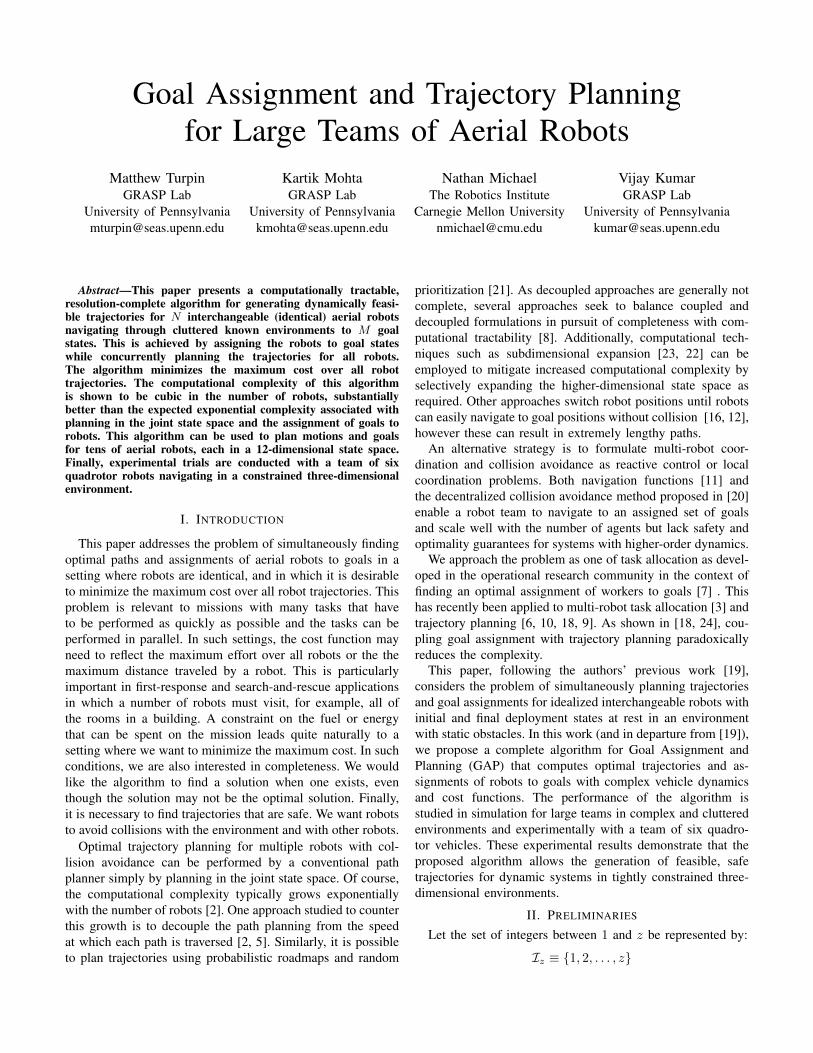
The algorithm presented in this paper was implemented on ateam of homogeneous quadrotors to navigate a complex maze-like environment. Figure 4 shows the test vehicle with a massof 75 g used in these experiments. To guide the experimentdesign, consider a scenario where a team of quadrotors entersa structure, explores a series of chambers connected by narrowpassageways, and departs the structure. The structure used forexperimentation, shown in Fig. 5, has been designed to bereconfigurable with small passageways. For this experiment,the passageways are configured such that there exist very longinternal paths within the structure.
Due to their dynamics, quadrotors require planning in a 12-dimensional state space to fully model the robots’ capabilities.Fortunately, the quadrotor has been shown to be differentiallyflat with flat outputs of position and yaw: x ∈ R3×SO(2). Forthe purpose of these experiments, orientation of the quadrotoris not relevant due to symmetry, so the state of the robots is theposition vector xi ∈ R3. Minimum snap trajectories have beenshown to be very well suited to quadrotors [13, 15] and thesetrajectories can be generated through a number of waypointsquickly and reliably.
In a closed environment as in these experiments, aerody-namic effects such as ground and inter-vehicle effects aresubstantial for the quadrotors, particularly between multiplerobots in a confined space. Therefore, B(x) is represented byan ellipsoid with elongated vertical dimension to minimizedownwash effects on other robots (as proposed in [14]).
The graph, G, is systematically generated by selecting alarge number of vertices vi ∈ R3 in and out of the structurewhich have zero velocity, acceleration, and jerk and respectthe conditions (1), (2). The trajectory τij is generated byminimizing snap to navigate from one vertex to the nextwhere the cost function used is the integral of snap over thetrajectory:
C(τij) =
∫ tf
to
....xi(t)
2 dt
Edge eij is added if ||vi − vj ||2
is below a threshold distanceand trajectory τij is obstacle collision-free.
Then, optimal individual trajectories are computed by usingDijkstra’s algorithm. Optimal assignment φ? and the totalordering ψ are then computed based on the optimal paths,boundary conditions, and path costs. Finally, time offsets arecomputed in order of priority ψ to ensure collision avoidanceof trajectories. Additional time is added to each time offsetrobots to minimize the effects of lingering aerodynamic tur-bulence and downwash.
As the quadrotor has homogeneous boundary conditions atevery vertex, the original trajectories tend to take a substantialamount of time. Therefore, trajectory refinement is used tocomplement the complex dynamics of the quadrotor. Thezero velocity, acceleration, and jerk boundary conditions arerelaxed where possible to allow the quadrotor to make fasterprogress and expend less energy. In many instances, this results
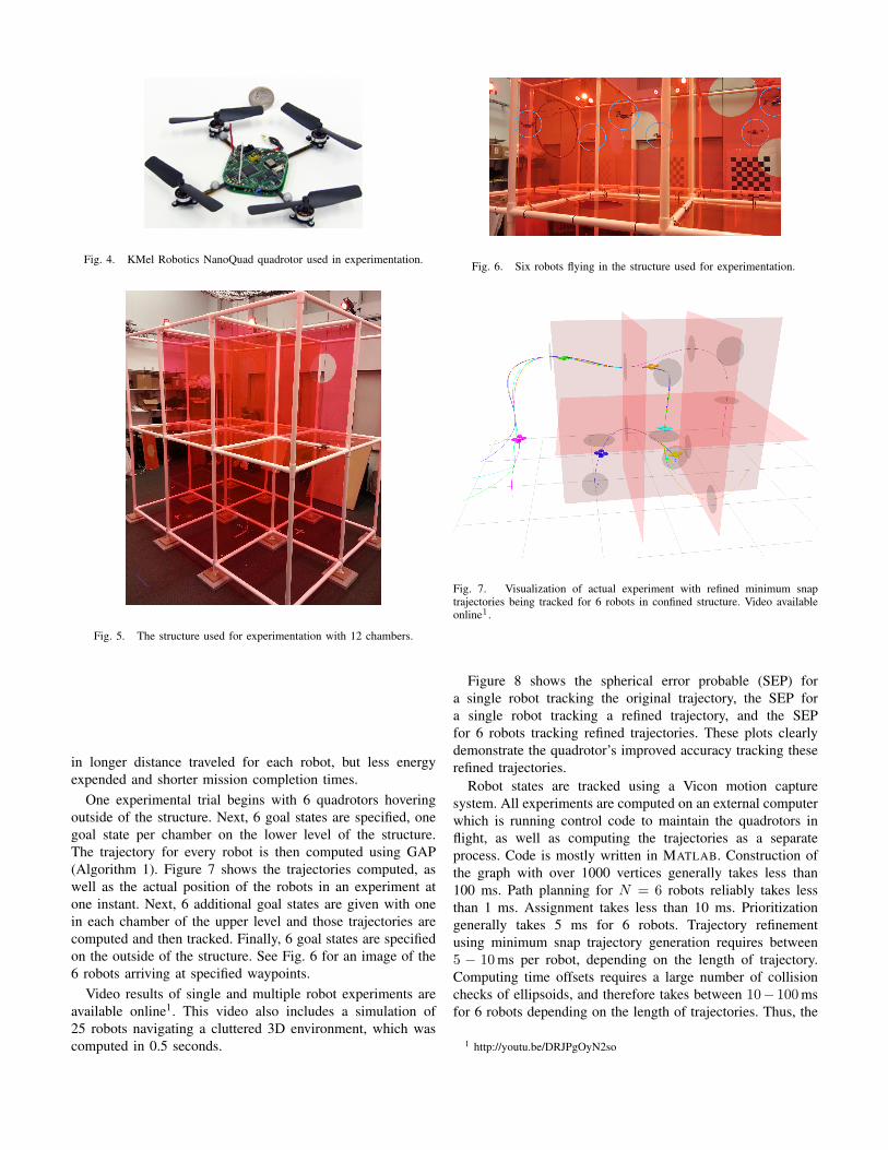
Fig. 4. KMel Robotics NanoQuad quadrotor used in experimentation.
Fig. 5. The structure used for experimentation with 12 chambers.
in longer distance traveled for each robot, but less energyexpended and shorter mission completion times.
One experimental trial begins with 6 quadrotors hoveringoutside of the structure. Next, 6 goal states are specified, onegoal state per chamber on the lower level of the structure.The trajectory for every robot is then computed using GAP(Algorithm 1). Figure 7 shows the trajectories computed, aswell as the actual position of the robots in an experiment atone instant. Next, 6 additional goal states are given with onein each chamber of the upper level and those trajectories arecomputed and then tracked. Finally, 6 goal states are specifiedon the outside of the structure. See Fig. 6 for an image of the6 robots arriving at specified waypoints.
Video results of single and multiple robot experiments areavailable online1. This video also includes a simulation of25 robots navigating a cluttered 3D environment, which wascomputed in 0.5 seconds.
Fig. 6. Six robots flying in the structure used for experimentation.
Fig. 7. Visualization of actual experiment with refined minimum snaptrajectories being tracked for 6 robots in confined structure. Video availableonline1.
Figure 8 shows the spherical error probable (SEP) fora single robot tracking the original trajectory, the SEP fora single robot tracking a refined trajectory, and the SEPfor 6 robots tracking refined trajectories. These plots clearlydemonstrate the quadrotor’s improved accuracy tracking theserefined trajectories.
Robot states are tracked using a Vicon motion capturesystem. All experiments are computed on an external computerwhich is running control code to maintain the quadrotors inflight, as well as computing the trajectories as a separateprocess. Code is mostly written in MATLAB. Construction ofthe graph with over 1000 vertices generally takes less than100 ms. Path planning for N = 6 robots reliably takes lessthan 1 ms. Assignment takes less than 10 ms. Prioritizationgenerally takes 5 ms for 6 robots. Trajectory refinementusing minimum snap trajectory generation requires between5 − 10 ms per robot, depending on the length of trajectory.Computing time offsets requires a large number of collisionchecks of ellipsoids, and therefore takes between 10− 100 msfor 6 robots depending on the length of trajectories. Thus, the
1 http://youtu.be/DRJPgOyN2so

0 0.2 0.4 0.6 0.8 10
0.05
0.1
0.15Er
ror (
m)
Fraction of Measurements Below Error
Fig. 8. Spherical Error Probable (SEP) for trials with 1 robot followingan unrefined trajectory (blue, dash dot), 1 robot following a refined trajectory(black solid), and 6 robots tracking refined trajectories as a team (red dashed).Notice that the refined trajectories give substantially lower error. Additionally,the initial trajectory takes 6 times longer than a refined trajectory to completeas it does not respect the quadrotor dynamics.
10 2
10 1
100
101
2 4 6 10 16 22 32 44 60 82Number of Robots
Tim
e to
Com
pute
(s)
Dijkstra SearchHungarian AlgorithmRefinementCollision AvoidanceGoal Assignment and PlanningLinear (N) Quadratic (N2) Cubic (N3)
Fig. 9. 100 simulation trials for each value of N to demonstrate time durationspent computing each stage of the algorithm applied to quadrotors. Note thatboth the planning (red) and refinement (green) grow roughly linearly in thenumber of robots and collision avoidance (pink) grows roughly quadratically.As the number of robots grows larger, the N3 complexity of the Hungarianalgorithm begins to dominate.
total computation time is typically just under 0.2 s to generatedynamically feasible trajectories for 6 quadrotors through atight space in MATLAB, however this could be optimizedsubstantially to get better performance.
A much larger environment, similar to the maze-like struc-ture in 5, was modeled in simulation to test the computationalrequirements as the number of robots grows much larger thanthe current experimental space allows. This simulated graphhas |V | > 104, |E| > 6 × 10⁵, which for N < 100 areroughly constant in the number of simulated robots. The timesof computation for each stage of the algorithm are displayedin Fig. 9.
This plot confirms the complexity analysis as a function ofthe number of robots in IV-C, where as the number of robotsincreases, solving the task assignment grows roughly cubicallyand begins to dominate the computation time at about 16
robots for the given parameters of the simulation. Of course, as|V | or |E| increase, the Dijkstra search will contribute more,moving the crossover of graph search and task assignment tohigher N .
VII. CONCLUSIONS AND FUTURE WORK
This paper presents a resolution-complete tractable trajec-tory generation method for a team of robots with arbitrar-ily complex dynamics. The algorithm is shown to providecollision-free trajectories for large numbers of robots. Theconcept of trajectory refinement allows us to incorporate thedynamics of the robot without substantially increasing thealgorithm’s complexity. This algorithm is then applied to ateam of quadrotor aerial vehicles.
In current work, we are pursuing distributed solutions aswell as relexing the assumption of completely interchangeablerobots. It also appears this algorithm could be very useful insolving the dynamic vehicle routing problem[17], but wouldrequire additional consideration to handle time evolving goalstates. Finally, the flexibility of the cost function may be usefulin creating algorithms for designing controllers which couldbe used for exploration with teams of robots.
ACKNOWLEDGMENTS
Research supported by: ONR Grant N00014-07-1-0829,ONR MURI Grant N00014-08-1-0696, NSF CCF-1138847,ARL Grant W911NF-08-2-0004, ONR Grant N00014-09-1-1051, Matthew Turpin was supported by NSF FellowshipGrant DGE-0822.
REFERENCES
[1] E.W. Dijkstra. A note on two problems in connexion withgraphs. Numerische mathematik, 1(1):269–271, 1959.
[2] M. Erdmann and T. Lozano-Perez. On multiple movingobjects. In Robotics and Automation. Proceedings. 1986IEEE International Conference on, volume 3, pages1419–1424. IEEE, 1986.
[3] B.P. Gerkey and M.J. Mataric. A formal analysis andtaxonomy of task allocation in multi-robot systems. TheInternational Journal of Robotics Research, 23(9):939–954, 2004.
[4] D. Hsu, L. Kavraki, J.C. Latombe, R. Motwani,S. Sorkin, et al. On finding narrow passages withprobabilistic roadmap planners. In Proc. Int. Workshopon Algorithmic Foundations of Robotics (WAFR), volume1998, 1998.
[5] K. Kant and S.W. Zucker. Toward efficient trajectoryplanning: The path-velocity decomposition. The Interna-tional Journal of Robotics Research, 5(3):72–89, 1986.
[6] S. Kloder and S. Hutchinson. Path planning forpermutation-invariant multirobot formations. Robotics,IEEE Transactions on, 22(4):650–665, 2006.
[7] H.W. Kuhn. The hungarian method for the assignmentproblem. Naval Research Logistics Quarterly, 2(1-2):83–97, 1955.

[8] S.M. LaValle and S.A. Hutchinson. Optimal motionplanning for multiple robots having independent goals.Robotics and Automation, IEEE Transactions on, 14(6):912–925, 1998.
[9] L. Liu and D. Shell. A distributable and computation-flexible assignment algorithm: From local task swappingto global optimality. In Proc. of Robot.: Sci. and Syst.,Sydney, Australia, July 2012.
[10] L. Liu and D.A. Shell. Multi-level partitioning anddistribution of the assignment problem for large-scalemulti-robot task allocation. In In Proc. of Robotics:Science and Systems, Los Angeles, CA, June 2011.
[11] Savvas G Loizou and Kostas J Kyriakopoulos. Nav-igation of multiple kinematically constrained robots.Robotics, IEEE Transactions on, 24(1):221–231, 2008.
[12] Ryan Luna and Kostas E Bekris. Push and swap: Fastcooperative path-finding with completeness guarantees.In Proceedings of the Twenty-Second international jointconference on Artificial Intelligence-Volume Volume One,pages 294–300. AAAI Press, 2011.
[13] D. Mellinger and V. Kumar. Minimum snap trajectorygeneration and control for quadrotors. In Proc. of theIEEE Intl. Conf. on Robot. and Autom., Shanghai, China,May 2011.
[14] N. Michael, D. Mellinger, Q. Lindsey, and V. Kumar.The GRASP multiple micro UAV testbed. IEEE Robot.Autom. Mag., 17(3):56–65, September 2010.
[15] M. J. Van Nieuwstadt and R. M. Murray. Real-timetrajectory generation for differentially flat systems. Intl.J. Robust and Nonlinear Control, 8(11):995–1020, De-cember 1998.
[16] Mike Peasgood, Christopher Michael Clark, and JohnMcPhee. A complete and scalable strategy for coordi-
nating multiple robots within roadmaps. Robotics, IEEETransactions on, 24(2):283–292, 2008.
[17] Harilaos N Psaraftis. Dynamic vehicle routing problems.Vehicle routing: Methods and studies, 16:223–248, 1988.
[18] M. Turpin, N. Michael, and V. Kumar. Trajectory plan-ning and assignment in multirobot systems. In Workshopon the Algorithmic Foundations of Robotics, Boston, MA,June 2012.
[19] M. Turpin, N. Michael, and V. Kumar. Computationallyefficient trajectory planning and task assignment for largeteams of unlabeled robots. In Proc. of the IEEE Int. Conf.on Robotics and Automation, May 2013.
[20] J. Van Den Berg, S. Guy, M. Lin, and D. Manocha. Re-ciprocal n-body collision avoidance. Robotics Research,pages 3–19, 2011.
[21] J.P. van den Berg and M.H. Overmars. Prioritized motionplanning for multiple robots. In Intelligent Robots andSystems, 2005.(IROS 2005). 2005 IEEE/RSJ Interna-tional Conference on, pages 430–435. IEEE, 2005.
[22] G. Wagner, M. Kang, and H. Choset. Probabilisticpath planning for multiple robots with subdimensionalexpansion. In Robotics and Automation (ICRA), 2012IEEE International Conference on, pages 2886–2892.IEEE, 2012.
[23] Glenn Wagner and Howie Choset. M*: A completemultirobot path planning algorithm with performancebounds. In Proc. of the IEEE/RSJ Int. Conf. on IntelligentRobots and Systems, pages 3260–3267, San Francisco,CA, Sept. 2011.
[24] Jingjin Yu and M LaValle. Distance optimal formationcontrol on graphs with a tight convergence time guaran-tee. In Decision and Control (CDC), 2012 IEEE 51stAnnual Conference on, pages 4023–4028. IEEE, 2012.


![1 Optimal Rendezvous Trajectory for Unmanned Aerial … · arXiv:1612.06100v2 [math.OC] 20 Dec 2016 1 Optimal Rendezvous Trajectory for Unmanned Aerial-Ground Vehicles A. Rucco, P.B.](https://static.fdocuments.net/doc/165x107/5ad60d117f8b9a5d058df0b0/1-optimal-rendezvous-trajectory-for-unmanned-aerial-161206100v2-mathoc-20.jpg)