
GNSS Signal Structures
45
Stansell Consulting RL GNSS Signal Structures Tom Stansell Stansell Consulting [email protected] Bangkok, Thailand 23 January 2018
Transcript of GNSS Signal Structures

S t a n s e l lC o n s u l t i n g
RL
GNSS Signal Structures
Tom StansellStansell Consulting
Bangkok, Thailand
23 January 2018

S t a n s e l lC o n s u l t i n g
RL
Slide 2
Introduction
It’s a pleasure to speak with you this morning. What follows are excerpts from three separate presentations.
Regards,
Tom Stansell

S t a n s e l lC o n s u l t i n g
RL
Slide 3
Source Presentations

Slide 2
The Goal of Interoperability
Ideal interoperability allows navigation with one signal each from four or more systems with no additional receiver cost or complexity
Interoperable = Better Together than Separate

Slide 3
Main Benefits of Interoperability
More Satellites Better Geometry Improves:
Satellite coverage Navigate where could not before
Dilution of Precision Accuracy is better everywhere Eliminates DOP holes (with open sky)
RAIM* Integrity checked everywhere, all the time Eliminates RAIM holes (with open sky)
Phase ambiguity resolution For survey and machine control applications
Accuracy Allows higher elevation angle cutoff which reduces multipath, ionospheric,
and tropospheric errors
* Receiver Autonomous Integrity Monitoring

Slide 4
Spectrum of GNSS Signals
NAVIC

Slide 5

Originally presented December 2008; Updated to current status and plans
2018

Slide 7
GPS Signals Summary
Center
Frequency
C/A BPSK(1) Open Service
P(Y) BPSK(10)
L1C TMBOC Open Service, Separate Pilot and Data Channels
M BOC(10,5)
P(Y) BPSK(10)
L2C BPSK(1) Open Service, Separate Pilot and Data Channels
M BOC(10,5)
L5 1176.45 MHz L5 BPSK(10) Open Service, Separate Pilot and Data Channels
1227.6 MHzL2
Band Signal Waveform Notes
L1 1575.42 MHz

Slide 8


Slide 10
Galileo Signals Summary
Center
Frequency
E1 OS CBOC Open Service, Separate Pilot and Data ChannelsPRS BOC(15,2.5)
CS BPSK(5) Commercial Service, Separate Pilot and Data ChannelsPRS BOC(10,5)
E5 1191.795 MHz E5a & E5b AltBOC(15,10) Open Service, Separate Pilot and Data Channels
Notes
E1 1575.42 MHz
E6 1278.75 MHz
Band Signals Waveform

Slide 11

Note: Some signal changes are being evaluated

Slide 13
Signal Plans


Slide 15
Future GLONASS Signal Spectrum

Slide 16
Signal Plans(From Several Presentations)


“QBOC”

11
GNSS Signals, Spectra, and Receiver Fundamentals

2

3

4
Simple Pseudorandom Code Generator
Code length = � = � = 15
C/A Code length = � = �� = 1023

5
Code Modulation Spreads the Spectrum

6
Frequency Domain

7
GNSS Spectra
E6B3E5b/B2b
L1, L2, & L5 are paramount, but also GLONASS, PRS, E5b, B3, & E6
NAVIC Note: NAVIC

8
GNSS L1 SpectrumP
ow
er
Sp
ec
tra
l D
en
sit
y (
dB
W/M
Hz)
Frequency (MHz)

9
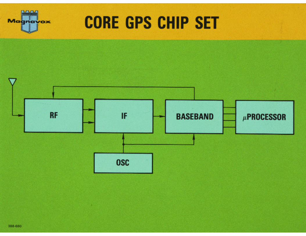
Receiver Signal Processing
10

11
27 Years with Just 3 GPS Signals
1978 to 2005
Direct civil access to C/A code
Indirect civil access by codeless and semi-codeless means

12
IIR-M Satellites Added Three More
20051978 to 2005
Direct civil access to L2C code
13
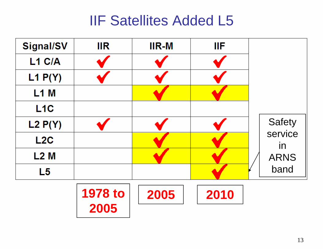
IIF Satellites Added L5
2005 20101978 to 2005
Safety service
in ARNS band

14
GPS III Will Add L1C
2005 20101978 to 2005
2018?
Better performance

15
Modernized Signal Structures• The most important improvements in GNSS
signal structures since1978 have been adopted for essentially every new and modernized signal– Including GPS, Galileo, BeiDou, and QZSS
– Hopefully also for NAVIC and GLONASS CDMA
• The improvements are (a) to have a data-less pilot carrier and (b) to use Forward Error Control (FEC) to enhance data reception
• There are many other variations, e.g.,– Binary Offset Carrier (BOC) combinations, spreading
code structures, FEC techniques, power split between data and pilot channels, symbol interleaving, etc.
– Each has a purpose, e.g., spectrum separation
© The Aerospace Corporation 2015
Signal Structure, Interoperability, and Geometry
Tom StansellConsultant to the Aerospace [email protected]
23 January 2018ICG Workshop, Bangkok, Thailand

2 © The Aerospace Corporation 2015
Disclaimer
The views and opinions expressed herein are those of the author and
do not necessarily reflect the official policy or position of The Aerospace Corporation or of any agency of the
U.S. government.
Portions of this work have been sponsored by The Aerospace Corporation

3 © The Aerospace Corporation 2015
The Most Important Ingredient
• Only Navigation by Satellite can provide excellent Geometry
– Continuous, worldwide, four dimensional, with excellent accuracy
– GDOP, Geometric Dilution of Precision, and its important children:
• PDOP, HDOP, VDOP, and TDOP
– Although the satellite signals may be weak, the geometry is strong
• No terrestrial navigation aid delivers “the most important ingredient”
• Do users need better geometry than GPS alone can provide?
• The answer is a definite “YES” as demonstrated by:
– Widespread use of GLONASS in products from consumer mobile phones to commercial survey and machine control products
• In spite of the difficulty of using GLONASS FDMA with GPS CDMA
– Plus widespread development of receivers to use all available GNSS
• Aircraft at altitude and ships at sea may not need more than GPS
– But integrity by A-RAIM requires many more satellites
• Users subject to signal blockage or outage do need more satellites
• Thus, the second most important ingredient is signal interoperability
– Enabling the best geometry by using every interoperable satellite signal
4 © The Aerospace Corporation 2015
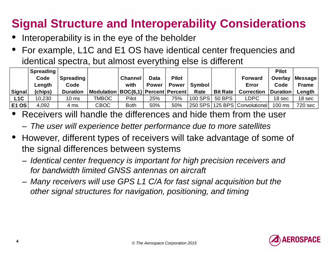
Signal Structure and Interoperability Considerations• Interoperability is in the eye of the beholder
• For example, L1C and E1 OS have identical center frequencies and identical spectra, but almost everything else is different
• Receivers will handle the differences and hide them from the user
– The user will experience better performance due to more satellites
• However, different types of receivers will take advantage of some of the signal differences between systems
– Identical center frequency is important for high precision receivers and for bandwidth limited GNSS antennas on aircraft
– Many receivers will use GPS L1 C/A for fast signal acquisition but theother signal structures for navigation, positioning, and timing
Signal
Spreading
Code
Length
(chips)
Spreading
Code
Duration Modulation
Channel
with
BOC(6,1)
Data
Power
Percent
Pilot
Power
Percent
Symbol
Rate Bit Rate
Forward
Error
Correction
Pilot
Overlay
Code
Duration
Message
Frame
Length
L1C 10,230 10 ms TMBOC Pilot 25% 75% 100 SPS 50 BPS LDPC 18 sec 18 sec
E1 OS 4,092 4 ms CBOC Both 50% 50% 250 SPS 125 BPS Convolutional 100 ms 720 sec

5 © The Aerospace Corporation 2015
Predicting the Future• If there are three global interoperable GNSS constellations in 2020
– GPS, Galileo, and BeiDou, with a total of 72 to 90 operational satellites
1. Use of GLONASS FDMA will decrease for precision applications– The current demand for more satellites will be satisfied by interoperable
CDMA signals, leaving little demand for the more difficult FDMA signals
2. Users will not say “this is my GNSS” or “this is my BeiDou”– There will be few if any GPS-only or BeiDou-only or Galileo-only receivers– Users won’t know and they won’t care where the signals originate– They will just enjoy the better performance provided by better geometry– And they probably will continue to call their device a “GPS” (sorry!)
3. Special, unique, or “orphan” signals will be little used– Use of GPS L2C will decline because no other GNSS provides it– The standard dual-frequency pair will become 1575.42 and 1176.45 MHz– E5b and B2b will be little used, whereas E5a and B2a will be widely used
• A lively discussion topic!

6 © The Aerospace Corporation 2015
Future Decrease in High Precision FDMA Use • A pure “time delay” Δt is characterized by a linear slope of phase
versus frequency
• However, a bandpass filter must rapidly attenuate signals outside the bandpass region
• This introduces nonlinearities in phase versus frequency, especially at the band edges
• In high precision applications it is desirable for every signal from every satellite to experience the same nonlinearities so there are no time delay differences between signals due to receiver filtering
• This will be true if every signal has the same center frequency
• Because this is not true for GLONASS FDMA signals, very careful calibration of each channel is required for near-precision results
• This is why high precision use of GLONASS FDMA will likely decrease substantially with deployment of Galileo and BeiDou
/ / ( / )f t t
Ph
as
e
Frequency

7 © The Aerospace Corporation 2015
Growth Continues and Should Accelerate
• Application growth is fueled primarily by the private sector
– Heavily regulated products, e.g., for aviation and the military, are slow to change and generally lag in innovation (sad but true)
• Factors that encourage innovation and application growth:
– Competition, Moore’s law, opportunity, fear, and the profit motive
• What in the future will stimulate growth:
– Much better GNSS geometry improves availability, continuity, integrity, and accuracy, especially in difficult environments
• Urban canyons, real canyons, open pit mining, even aviation
– A-RAIM will become practical and begin to displace SBAS use
– Ambiguity resolution for Real Time Kinematic (RTK) in survey and machine control will become almost instantaneous and more reliable
• Improved vertical accuracy will displace some laser plane requirements
• Alternate means to communicate message parameters will promote “instant navigation” for all applications (push to navigate)