
GNSS REFERENCE STATION INSTALLATION AND OPERATION · PDF fileGNSS REFERENCE STATION...
20
BEST PRACTICES FOR GNSS RTK SERVICE PROVIDERS September 1, 2017 1 GNSS REFERENCE STATION INSTALLATION AND OPERATION BEST PRACTICES Acknowledgement 2 Preface 2 1.0 Introduction 2 2.0 Terms and Definitions 3 3.0 Installation 4 3.1 Site Location 4 3.2 Satellite Visibility 5 3.3 Radio Frequency Environment 6 3.4 Antenna Mounting 6 3.5 Ground-based Monuments 7 3.5.1 Pillars 7 3.5.2 Braced 8 3.6 Roof-based Monuments 9 3.6.1 Structural Support 9 3.6.2 Attachment to Structure 9 4.0 Operation 12 4.1 Antenna 12 4.2 Receivers 13 4.3 Power and Computing 13 4.4 Communication and Data Access 14 4.5 Quality Control 14 Final Remarks 15 References: 15 Appendix 1: Recommended Directory and File Naming Conventions 17 Appendix 2: Frost Depth Information 20
Transcript of GNSS REFERENCE STATION INSTALLATION AND OPERATION · PDF fileGNSS REFERENCE STATION...

BEST PRACTICES FOR GNSS RTK SERVICE PROVIDERS September 1, 2017
1
GNSS REFERENCE STATION INSTALLATION AND OPERATION
BEST PRACTICES
Acknowledgement 2 Preface 2
1.0 Introduction 2 2.0 Terms and Definitions 3
3.0 Installation 4 3.1 Site Location 4 3.2 Satellite Visibility 5 3.3 Radio Frequency Environment 6
3.4 Antenna Mounting 6 3.5 Ground-based Monuments 7
3.5.1 Pillars 7
3.5.2 Braced 8 3.6 Roof-based Monuments 9 3.6.1 Structural Support 9
3.6.2 Attachment to Structure 9 4.0 Operation 12
4.1 Antenna 12 4.2 Receivers 13
4.3 Power and Computing 13 4.4 Communication and Data Access 14
4.5 Quality Control 14 Final Remarks 15 References: 15
Appendix 1: Recommended Directory and File Naming Conventions 17 Appendix 2: Frost Depth Information 20
BEST PRACTICES FOR GNSS RTK SERVICE PROVIDERS September 1, 2017
2
Acknowledgement The following Best Practice guidelines are based on a document originally developed by Service Nova
Scotia as part of their efforts to modernize the Nova Scotia Coordinate Reference System. Monument
design information was inspired from Guidelines for New and Existing Continuously Operating Reference
Stations (CORS), NGS, NOS, NOAA, Silver Spring, MD 20910, February 2006
(http://geodesy.noaa.gov/CORS/Establish_Operate_CORS.shtml).
The Canadian Geodetic Survey (CGS) welcomes feedback on the content of this document. Please contact:
Canadian Geodetic Survey 336A-588 Booth Street Ottawa, Ontario Canada K1A 0Y7 Phone: 1-343-292-6617 (Monday - Friday, 07:00 - 16:00 EST) Email: [email protected]
Preface
In Canada, public sector agencies have traditionally assumed the responsibility to provide coordinates for
geodetic control points, along with the standards and products that support access to a consistent national
geospatial infrastructure. With GNSS technology, end-users now rely heavily on data acquired and
disseminated directly from GNSS tracking stations - known as active control stations (ACS) or Real-time
kinematic references (RTK). This mode of operation may affect open and reliable access to a consistent
geodetic reference frame unless proper practices are followed for station installation and operation.
As the ‘active’ component of our national positioning infrastructure is being densified and expanded, a
strategy for integrating the coordinates of all reference stations into the CSRS is required to maintain the
consistency of the geodetic fabric. These best practice guidelines for reference station operators should
encourage the selection of suitable locations and deployment of proper GNSS equipment to meet the
performance requirements of most users. In particular, they should help protect the interests of Professional
Land Surveyors who rely on them and are the gateway to land administration processes in Canada.
1.0 Introduction
The provision of a national Coordinate Referencing System (CRS) has been the mandate of the Canadian
Geodetic Survey (CGS) since the early 1900’s. Currently, NAD83(CSRS) at epoch 2010 is the most up to
date CRS for Canada. A CRS is usually materialized by an integrated network of monumented geodetic
control points observed periodically (passive) or continuously (active); and whose coordinates are made
accessible to end-users through data and products. Today, the precise coordinates of the antenna phase
centers of GNSS satellites or reference stations have also become part of our national CRS, although they
aren’t physical objects anchored to the Earth’s crust, as traditional survey control markers.
BEST PRACTICES FOR GNSS RTK SERVICE PROVIDERS September 1, 2017
3
While CGS is responsible for the national realization of NAD83(CSRS), provincial agencies have the
authority to adopt specific epochs of NAD83 realization within their jurisdiction. To date, this fact has led to
the adoption of 2 distinct epochs of NAD83 realization across Canada, 1997 and 2002. These different
epoch realizations introduce coordinate discrepancies of a few centimetres along some provincial borders.
The provincial CRS is usually the foundation that supports all geographic information. When functioning at
a high level, a consistent CRS leads to better asset management and infrastructure development. It is the
role of the Province to represent the best interest of its citizens by ensuring that accuracy and widespread
access to the provincial CRS are provided on an ongoing basis.
Dissemination of GNSS data from continuously operating ACS or RTK stations (or networks) has become
a popular means of providing precise access to geodetic coordinate referencing systems. As Canadians
look to embrace this technology, it is important to encourage the use of best practices to install and operate
ACS/RTK stations and monitor their stability. This document has been compiled for that purpose. This
document is also meant to complement the Guidelines for RTK GNSS Surveying in Canada available from
Natural Resources Canada. By clearly defining Best Practices for GNSS Reference Station operators and
end users, more consistent outcomes are likely to be achieved.
These guidelines specify best practices for various components of an RTK station operation that address
concerns with:
a) Monument location, antenna stability and satellite visibility;
b) GNSS equipment specification and deployment ;
c) Communication and data/metadata standards;
These guidelines are intended to facilitate the integration of RTK references into the CACS network and to
encourage the use of NAD83(CSRS) integrated coordinates by GNSS NRTK service providers..
2.0 Terms and Definitions
As the guidelines are intended to encourage RTK Providers to adhere to best practices, the term should is
used throughout the document to reflect its recommendations. Adherence to the recommended practices
should enable the provision of GNSS corrections that support positioning with centimetre precision (1 sigma
in each component) traceable to the NAD83(CSRS).
The following definitions have been adopted for this document:
Active Control Station: GNSS hardware that is permanently setup over a coordinated reference
mark for the purpose of distributing corrections for Differential GNSS positioning.
Antenna Phase Center (APC): the electrical point, within or outside an antenna, at which the GNSS
signal is measured. The realization of the phase center is determined by the set of antenna phase
center variations (PCV) corrections to account for the non-ideal electrical response as a function of
elevation and azimuth angles.

BEST PRACTICES FOR GNSS RTK SERVICE PROVIDERS September 1, 2017
4
Antenna Reference Point (ARP): The point on the exterior of the antenna to which the antenna
height is measured.
Antenna eccentricity: The vertical and horizontal distances from the mark to the ARP.
Monument: The structure (e.g., pillar, building…etc.), including the mount, which keeps the GNSS
antenna attached to earth’s surface
Mount: the device used to attach the antenna to the monument
Mark: a unique and permanent point on the monument to which the antenna reference point is
measured. This mark should remain invariant with respect to the monument.
Site operator: Person responsible for operating an ACS site
Site log: Plain ASCII file that contains all historical information about a site and details the
equipment and monument used.
3.0 Installation
No reference site installation is perfect. There are, however, designs that are known to cause (or will likely
cause) degradation in data quality, which should be avoided. The guidelines in the following sub-sections
will help to ensure that the deployment of GNSS equipment at a reference site delivers high quality data. In
general, the following factors should be considered in order of importance when choosing the best location
for an ACS monument:
1. Site location
2. Satellite visibility
3. Data degradation factors
4. Equipment security
5. Proximity to power and communications
3.1 Site Location
The location of a site should be selected to maximize the stability of the GNSS antenna reference point
(maintain a fixed position in three dimensions) and minimize measurement of near-surface effects. The
uppermost part of the ground is subject to the greatest amount of motion (e.g., soil expansion and
contraction due to changes in water saturation, frost heave, soil weathering). Generally, increasing the depth
of the monument improves its stability. Ensuring that an antenna is well anchored to the ground through the
monument is essential so that the position and velocity associated with a given site represents the crustal
position and velocity of the site, not just that of the antenna. Detailed discussion of benchmark stability and
monument can be found in GSD (1978), NOAA (1978) and USACE (2012).
ACS sites should be designed to minimize the impact of:

BEST PRACTICES FOR GNSS RTK SERVICE PROVIDERS September 1, 2017
5
Caverns, sink holes, and mines
Areas where there is active fluid/gas pumping
Frost heave, shrinking and swelling of soil and rock
Soil expansion and contraction
Slope instability
Soil consolidation
Motion intrinsic to a monument e.g. thermal expansion and contraction
If the soil and geological conditions are questionable, a conservative, “worst case” scenario should be
assumed.
3.2 Satellite Visibility An open area with minimal obstructions and minimum likelihood of change in the environment surrounding
the monument should be chosen. Avoid sites with future tree or shrub growth, building additions, rooftop
additions, new antenna masts, satellite dishes, parking lots, chain link fences…etc. Also avoid nearby (within
30 m) reflectors such as vehicles, metal walls and metal signs which can cause signal multipath.
Obstructions should be kept below 10 degrees above the horizon from the ARP and there should be minimal
obstructions from 0 to 10 degrees (see Figure 1). The greater the volume through which
uninterrupted/unreflected signals can reach the antenna, the greater the likelihood of a robust position
estimate. Lightning rods, broadcast antennas or other objects should not extend above the antenna or be
anywhere within 3 m of the antenna and all should be below the 0 degree of the horizontal surface containing
the ARP.
Figure 1: Obstruction-Free Zone around the Antenna

BEST PRACTICES FOR GNSS RTK SERVICE PROVIDERS September 1, 2017
6
3.3 Radio Frequency Environment
The signals received by an ACS antenna and receiver can be detrimentally affected by interference from
other radio frequency sources (e.g. TV, microwave, FM radio stations, cellular telephones, VHF and UHF
repeaters, RADAR, high voltage power lines). This can cause additional noise, intermittent or partial loss of
lock or even render sites inoperable. Every effort should be made to avoid proximity to such equipment.
When present, all such equipment should be documented in the site log.
3.4 Antenna Mounting
A device should exist between the monument and the antenna so that:
a) the antenna can be levelled and oriented to north; and
b) when the antenna is changed, the new ARP can be returned to the exact same point in 3-
dimensional space as the previous ARP or the change in position between the mark and the ARP
should be measured to within ±1 mm.
If the antenna is simply attached to a threaded rod, the new antenna may not return to the same 3-D position
or may be oriented differently (the latter would be immaterial only if the phase center variation model is
perfectly symmetrical). Both events would require a new position to be computed, which is undesirable. The
antenna should be leveled to within 0.15 degrees or 2.5 mm/meter (this is easily achieved using a good
quality spirit level available in most hardware stores). Tribrach’s are not permitted, as there is no mechanism
to lock the adjustable wheels in place. A number of devices exist that will do this (see Figure 2). For example:
www.ngs.noaa.gov/CORS/Articles/modifying_a_tribrach_adaptor.pdf
UNAVCO GNSS Antenna Mounts
Figure 2: Antenna Mount
The antenna should be oriented to true north using the convention of aligning the antenna cable attachment
point, unless the antenna has a different inscribed North point. Remember that declination is the angle
between magnetic north and true north. A magnetic declination calculator for setting a compass correctly is
available at: http://geomag.nrcan.gc.ca/calc/mdcal-eng.php. The declination used should be recorded in the

BEST PRACTICES FOR GNSS RTK SERVICE PROVIDERS September 1, 2017
7
log file (see Section 4.4. Site Log). All antenna phase center patterns assume an oriented antenna, and
phase center values can differ between north and east by up to a centimeter.
The antenna cable should not be under tension. Looping the first section of cable next to the antenna and
attaching it to the mount can best avoid this problem. If the cable is not encased in conduit, then care should
be taken that it will not move around and be damaged. Take particular care at any point where the cable is
subject to increased friction, e.g. edges and egress points. Typical GNSS antenna cables for ACS
(RG213/RG214) have a signal loss of 9 db/100ft/30m at 1Ghz. Total loss for installed length of cable at an
ACS should be 9 db or less, implying a maximum cable length of 100ft/30m. If a longer cable is needed
then a lower loss cable should be used (The type, manufacturer, and length of cable should be listed in the
Site Log, see4.4).
The antenna cable should directly connect to the receiver and antenna or antenna splitter. No connectors
should be inserted to convert connector types (E.g., TNC to N-type). The junction point of the antenna cable
and antenna after the two have been connected should be sealed with waterproof material (E.g., butyl wrap).
Site operators should insert a lightning arrestor in the antenna cable between the antenna and the receiver
with its own independent ground. The arrestor should be located on the outside of the building at or near
the egress point of the cable into the building. This should protect the receiver in the event of a lightning
strike on or near the antenna. The following URL may be helpful, and clearly indicates the potential signal
loss created by a poorly selected arrestor:
http://kb.unavco.org/kb/article.php?id=462
When the antenna is not in a secure location, a security mechanism is required to minimize the chance of
the antenna assembly being removed. Schmidt et al. (2000) provide an example of a security mechanism.
3.5 Ground-based Monuments
3.5.1 Pillars
Ground-based pillar-type monuments adhere to the following guidelines:
i. Should be approximately 1.5 m above the ground surface to mimic the geometry used at NGS’s
antenna phase center calibration facility. In the event that obstructions exist, a taller monument may
be necessary.
ii. Should have a deep foundation (e.g., concrete or bedrock), that extends at least 4 m below the frost
line (see Appendix 2) and/or the center of mass of the pillar should be below the frost line.
iii. The top of the pillar should be narrower than the widest part of the antenna, and the smaller the
surface the better. In constructing the pillar, consider that future antennas may be smaller; hence
the narrower the top of the pillar the better. The distance between the top of the pillar (if it has a
surface) and the antenna should be less than 5 cm or greater than 1 GNSS wavelength (~20 cm).
This will allow enough room to manipulate a leveling and orienting device. These recommendations

BEST PRACTICES FOR GNSS RTK SERVICE PROVIDERS September 1, 2017
8
apply to the top of the pillar only; a very narrow pillar would be unstable and not recommended,
however tapered pillars are good. These guidelines will mitigate multipath issues. The steel pillar
design illustrated in Schmidt et al. (2000) is recommended (see Figure 3).
Figure 4 illustrates a concrete pillar styled monument.
3.5.2 Braced
Braced monuments (see Figure 3) are especially stable and well anchored to the ground, although they
more expensive than pillars. Extensive diagrams with details of all aspects of constructions are available
through UNAVCO at:
http://pboweb.unavco.org/?pageid=45
http://kb.unavco.org/kb/category/gnss-and-related-equipment/monumentation/deep-drilled-braced/109/
Figure 3 : GPS pedestal monument (Schmidt
et al., 2000)
Figure 4 : Ground based, concrete pillar monument
Figure 5 : Braced monument (UNAVCO, 2012)

BEST PRACTICES FOR GNSS RTK SERVICE PROVIDERS September 1, 2017
9
3.6 Roof-based Monuments
3.6.1 Structural Support
Masonry buildings or buildings constructed of structural steel anchored to a concrete foundation are
permitted. Solid brick or reinforced concrete buildings are recommended. The building should be at least 5
years old to increase the likelihood that all primary settling of the building has occurred. There should be no
visible cracks on the outside or inside walls. To minimize the effects of thermal expansion as well as
multipath issues, the following characteristics are not recommended:
i. Buildings taller than two stories.
ii. Buildings constructed of wood.
iii. Metal frame buildings with metal walls or roof.
3.6.2 Attachment to Structure
The following guidelines are used for locating and attaching ACS hardware to buildings:
i. Stainless steel or galvanized steel is recommended for longevity (Angle iron or circular pipe).
Aluminum is not recommended as it has approximately twice the thermal expansion of
steel/concrete
ii. The antenna mount should be bolted directly to the main part of the building; a load-bearing wall
near a corner is recommended.
iii. The use of epoxy and threaded lock adhesives fasteners (bolts/anchors/rods) is strongly
recommended.
iv. Mounting on a chimney is not recommended unless it has been filled with concrete or if it is
particularly robust.
v. The mount should not interfere with the building’s replaceable roof. This will minimize the
likelihood that the mount will be disturbed when the roof is replaced.
vi. Attaching laterally to a load bearing wall:
a. The mount should extend about 0.5 m above the roofline and be attached to the building
for a length of at least 1 m, with at least 2 anchors/bolts (3 or more is preferred). The ratio
of freestanding part to bolted part should be 1:2 or greater.
b. The bolts/anchors should penetrate directly through the mount (no u-bolts or unistrut
brackets with metal ties/clamps). Spacers to keep the mount from sitting flush against the
wall are acceptable.
vii. Attaching vertically to a master wall:
a. A bolt or rod should be anchored into a load-bearing wall.
b. Take care not to void a roof warranty.

BEST PRACTICES FOR GNSS RTK SERVICE PROVIDERS September 1, 2017
10
c. Avoid metal flashing on a parapet wall.
viii. Aesthetics should be considered before leaving a site, especially when leasing equipment space.
Masts should be blended into the natural color scheme of the building. Dark colours should be
avoided to minimize thermal effects. Paint will also help to avoid corrosion of some materials.
Figure 6 illustrates an antenna mast attached to a load bearing wall, which uses through bolts for mounting
(Figure 7).
Despite having metal siding, the building in Figure 8 has a concrete inner wall. The antenna mast is mounted to the concrete inner wall using through bolts (Figure 9).
Figure 6 : Antenna mast attached to a load bearing wall
Figure 7 : Through bolts for mounting

BEST PRACTICES FOR GNSS RTK SERVICE PROVIDERS September 1, 2017
11
Figure 8 : Metal siding with concrete inner wall
installation
Figure 9 : Through bolts in concrete inner
wall
Some locations, such as the one shown in Figure 10, necessitate some ingenuity. Nearby obstructions
made the best choice for antenna location at the top of the spire. The antenna is fastened directly to
structural steel.
Figure 10: Spire installation
BEST PRACTICES FOR GNSS RTK SERVICE PROVIDERS September 1, 2017
12
4.0 Operation
Continuous and reliable operation of a GPS reference site requires that all equipment deployed meets
required specifications and is properly configured. In general, characteristics of the following components
of a GNSS tracking station are specified to ensure that the end-user requirements are met in terms of RTK
service availability and positioning accuracy:
1. Antenna
2. Receiver
3. Power and Computing
4. Communication and Archiving
5. Quality Control
6. Proximity to power and communications
It is strongly recommended that equipment be upgraded and/or replaced as technology evolves (e.g., new
GNSS signals are added). Equipment changes should, however, be minimized as they have the potential
of introducing a change in position.
4.1 Antenna
A consistent phase center and ARP for the antenna is essential to relate the GNSS measurements to the
reference mark on the monument. Ignoring the phase center variations can lead to errors of several
centimeters. All analysis of GNSS data should be performed using an NGS-validated phase center model
included in the calculation of the official positional coordinates for an ACS site. Antennas should be
inspected at least annually for damage.
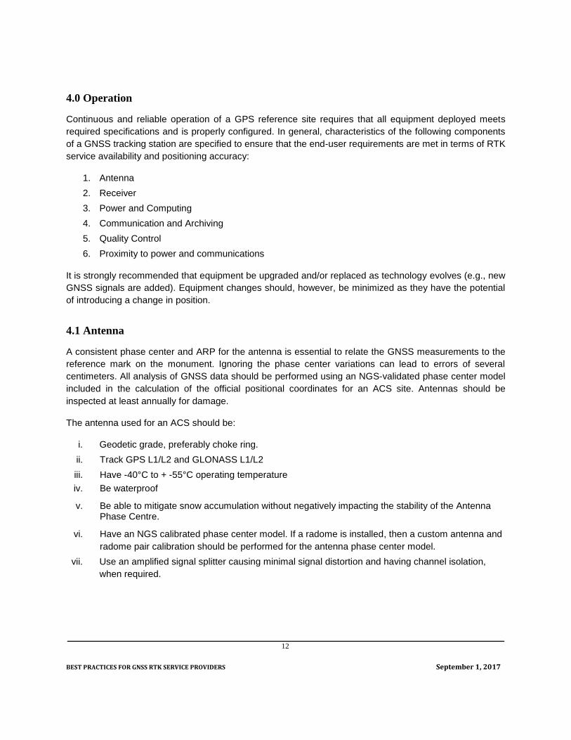
The antenna used for an ACS should be:
i. Geodetic grade, preferably choke ring.
ii. Track GPS L1/L2 and GLONASS L1/L2
iii. Have -40°C to + -55°C operating temperature
iv. Be waterproof
v. Be able to mitigate snow accumulation without negatively impacting the stability of the Antenna Phase Centre.
vi. Have an NGS calibrated phase center model. If a radome is installed, then a custom antenna and
radome pair calibration should be performed for the antenna phase center model.
vii. Use an amplified signal splitter causing minimal signal distortion and having channel isolation,
when required.

BEST PRACTICES FOR GNSS RTK SERVICE PROVIDERS September 1, 2017
13
4.2 Receivers
Site operators should keep all receiver firmware current. Network administrators should be notified before
planned updates occur. ACS receivers should have the following characteristics:
i. Track GPS L1/L2 signals and GLONASS L1/L2 signals and be capable of tracking modern signals
(GPS L2C/L5, Galileo, Compass).
ii. Track at least 14 satellites on L1 and L2 above 0 degrees
iii. Provide L1 C/A-code pseudorange or P-code pseudorange and L1 and L2 full wavelength carrier
phase
iv. Sample at a frequency of at least 1 Hz
v. Support NTRIP client and server (supporting at least 10 simultaneous clients) functionality
vi. Support RTCM SC104 versions 2.x and 3.x input/output
vii. -40°C to + 55°C operating temperature
viii. Power Consumption < 10 W
ix. L1 and L2 carrier phase measurement precision < 2 mm (RMS)
x. Data storage capacity for at least 24 hours of 1 Hz raw data
xi. Ethernet interface
Receivers should be configured so that:
i. Smoothing is not applied to the observables
ii. Tracking occurs with an elevation cutoff angle of 0 degrees
iii. Observations are recorded at a sampling interval of at least 1 Hz.
iv. Hourly blocks (strongly preferred), or 24 hr blocks of data are logged according to GNSS time.
v. Tracking occurs for all satellites regardless of health status since the US Department of Defense’s
criteria for designating an unhealthy satellite is not always applicable to ACS users.
4.3 Power and Computing
All ACSs should have an uninterruptible power supply that provides at least 24 hours of back up operating
time for the receiver and any other equipment necessary to archive at least 24 hours of raw data at the
receiver sampling interval.
GNSS RTK Service Providers should use redundant server infrastructure for delivering ACS data to users.
Each server should be connected to an uninterruptible power supply that can deliver at least 2 hours of
operation time in the event of a power outage. The service delivery system should be scalable to support
potentially thousands of users.

BEST PRACTICES FOR GNSS RTK SERVICE PROVIDERS September 1, 2017
14
4.4 Communication and Data Access
Access to data files from the GNSS NRTK Service Provider’s server should be done via the internet. GNSS
data files should be transferred using the Internet File Transfer Protocol (FTP). The stored data should be
retrievable immediately after the hour, either hourly or at the end of the day (24h00 GNSS time). The GNSS
NRTK Service Provider’s web and FTP server should support continuous file access.
All file names and associated dates should be recorded with respect to GNSS time, not local time. Most
GNSS receivers will automatically convert UTC to GNSS time. Recommendations on directory structure
and file naming conventions are given in Appendix 1.
The GNSS NRTK Service Provider’s should store the observed tracking data in its native format and also
make it available in ASCII RINEX format (Version 2 or higher).
A set of sharply focused digital photographs (at least 1 megapixel images) are required to document a site.
The photographs should give a clear view of the equipment being used, how it is assembled, as well as the
space around it for someone who has not visited the site. These photographs should be updated if the
equipment changes or changes occur in the physical space around the antenna.
A site log containing all the historical information about a site and detailing the equipment and monument
used is essential. The site log is as important as the GNSS data collected at a site. It should follow the
format specified by the International Global Navigation Satellite System Service (IGS). A blank site log
template is found at http://igscb.jpl.nasa.gov/igscb/station/general/blank.log.
All parts for which information is available should be filled. Any empty or inapplicable sections should not
be deleted. These files should be “machine readable” and therefore saved as ASCII files and have the
exact spacing described in the instructions found at
ftp://igscb.jpl.nasa.gov/pub/station/general/sitelog_instr.txt.
Most entries can only be on one line, if more information is needed it should be entered it in the Additional
Information part of each section. Examples of Site Log files can be found at http://www.igs.org/network .
4.5 Quality Control
The quality of the observations made by a GNSS reference station can be determined by the repeatability
and long-term stability of the coordinates estimated for its antenna phase center. The computation of
coordinates within a particular geodetic reference frame, such as NAD83(CSRS), is done by integrating the
reference station into an existing control network. This can be accomplished on a continuous basis at
prescribed intervals by combining data from the GNSS reference with surrounding active control stations in
a least-squares network adjustment. An alternate method is to occupy a number of monumented passive
control points around the reference station and periodically estimate coordinates with differential processing.
While possible, this method is less efficient and does not provide the opportunity for continuous monitoring
of the station position.
Assigning coordinates to the station data in the RTK software used to compute single-station or network

BEST PRACTICES FOR GNSS RTK SERVICE PROVIDERS September 1, 2017
15
corrections is also critical to ensure that user solutions are in a well-defined and traceable reference frame.
NAD83(CSRS) coordinates with epoch of realization are recommended.
Therefore, GNSS RTK Service Providers should:
a) Monitor data acquisition processes to detect sites that are not operating.
b) Perform daily network adjustments or single-station PPP processing to detect unstable
reference stations
c) Report reference stations that experience sudden coordinate changes. As a rule of thumb,
reference stations should be considered unstable if coordinate changes exceed:
i. 5 mm horizontally or 10 mm vertically in less than 1 hour or
ii. 10 mm horizontally and 15 mm vertically in a 24 hour period
Final Remarks
The information contained in this document was compiled to inform GNSS RTK Providers of considerations
to make when installing a GNSS Reference Station for continuous operations. The recommendations are
directed in particular to providers who intend to deliver geodetic quality positioning solutions in a standard
reference frame, such as NAD83(CSRS). Given the benefits of integrating geospatial information into a
nationally consistent reference frame to preserve its long-term value, all providers are encouraged to adopt
the proposed best practices and contribute to sustaining a nation-wide consistent and accurate geodetic
reference.
References:
Eng. Toolbox, 2012. Coefficients of Linear Thermal Expansion, The Engineering Toolbox. http://www.engineeringtoolbox.com/linear-expansion-coefficients-d_95.html.
GSD, 1978. Specifications and Recommendations for Control Surveys and Survey Markers. Geodetic Survey Division, Natural Resources Canada.
NOAA, 2006. Guidelines for New and Existing Continuously Operating Reference Stations (CORS), 2006. National Geodetic Survey National Ocean Survey, NOAA, Silver Spring, MD 20910. http://www.ngs.noaa.gov/PUBS_LIB/CORS_guidelines.pdf
NOAA, 1978. NOAA Manual NOS NGS 1. Geodetic Bench Marks. U.S. Department of Commerce. National Oceanic and Atmospheric Administration, National OceanSurvey, Rockville, Md. http://www.ngs.noaa.gov/PUBS_LIB/GeodeticBMs/
Schmidt, M., H. Dragert, W. Hill, N. Courtier, 2000. New GPS monument design for permanent GPS installations in the Western Canada Deformation Array. Proceedings, IGS Network Workshop 2000, 12-14 July 2000, Soria Moria, Oslo, Norway.
SNSMR, 2012. NSCRS Modernization Strategy. Draft strategy document available through Service Nova Scotia and Municipal Relations - Geographic Information Services.
UNAVCO, 2012. Permanent Station GPS/GNSS, 2012. UNAVCO. http://kb.unavco.org/kb/article/unavco-resources-permanent-gps-gnss-stations-634.html

BEST PRACTICES FOR GNSS RTK SERVICE PROVIDERS September 1, 2017
16
URECON, 2012. Ambient Temperatures – Below Ground. Frost Depth. http://www.urecon.com/applications/municipal_ambient_below.html.
USACE, 2012. Survey Markers and Monumentation, 2012. US Army Corps of Engineers. http://www.publications.usace.army.mil/Portals/76/Publications/EngineerManuals/EM_1110-1-1002.pdf

BEST PRACTICES FOR GNSS RTK SERVICE PROVIDERS September 1, 2017
17
Appendix 1: Recommended Directory and File Naming Conventions
Native data:
/base_directory/native/yyyy/ddd/ssss/ssssdddh[mm].[c]
RINEX data:
/base_directory/rinex/yyyy/ddd/ssss/ssssdddh[mm].yyt.[c]
If the GNSS NRTK Service Provider wants to deliver RINEX observation, meteorological, navigation…etc.
files as a group of files, the files within the archive should be uncompressed and the archive should be
labeled:
ssssdddh[mm].yy.c
Files should use the following convention all in lowercase, which follows the RINEX convention:
ssssdddh[mm].yyt.[c]
The following symbology is used:
base_directory: any directory on the site operator’s ftp server where data are going to be stored.
ssss: the four-character site ID
ddd: the GNSS day of year
yyyy: four digit GNSS year
h: a letter that corresponds to an hour-long GNSS time block (see below) or 0 (zero) for a full 24hr
GNSS time block.
00 01 02 03 04 05 06 07 08 09 10 11 12 13 14 15 16 17 18 19 20 21 22 23
a b c d e f g h I j k l m n o p q r s t u v w x
mm: applies only to sites that record in less than 1 hour time blocks and consists of the minutes
after the hour that the file begins e.g. if 30 minute files are collected then 00 and 30 would be
used.
yy: the last two digits of four digit GNSS year (e.g. 2004 is 04)
t: the file type as:
Type Description
o Observation
d Observation Hatanaka compressed. The source code
for creating and uncompressing this format is available
at: http://terras.gsi.go.jp/ja/crx2rnx.html
m Meteorological
BEST PRACTICES FOR GNSS RTK SERVICE PROVIDERS September 1, 2017
18
n Navigation
s Summary
c Compression is optional, but recommended to save
bandwidth. One of the following formats should be
used:
a) zip – zip
b) gz – gzip GNU zip (preferred) and available at:
http://www.gnu.org/software/gzip/
c) Z – UNIX compressed
The native binary files will have manufacturer specific extensions but should mimic the aforementioned
format as closely as possible.
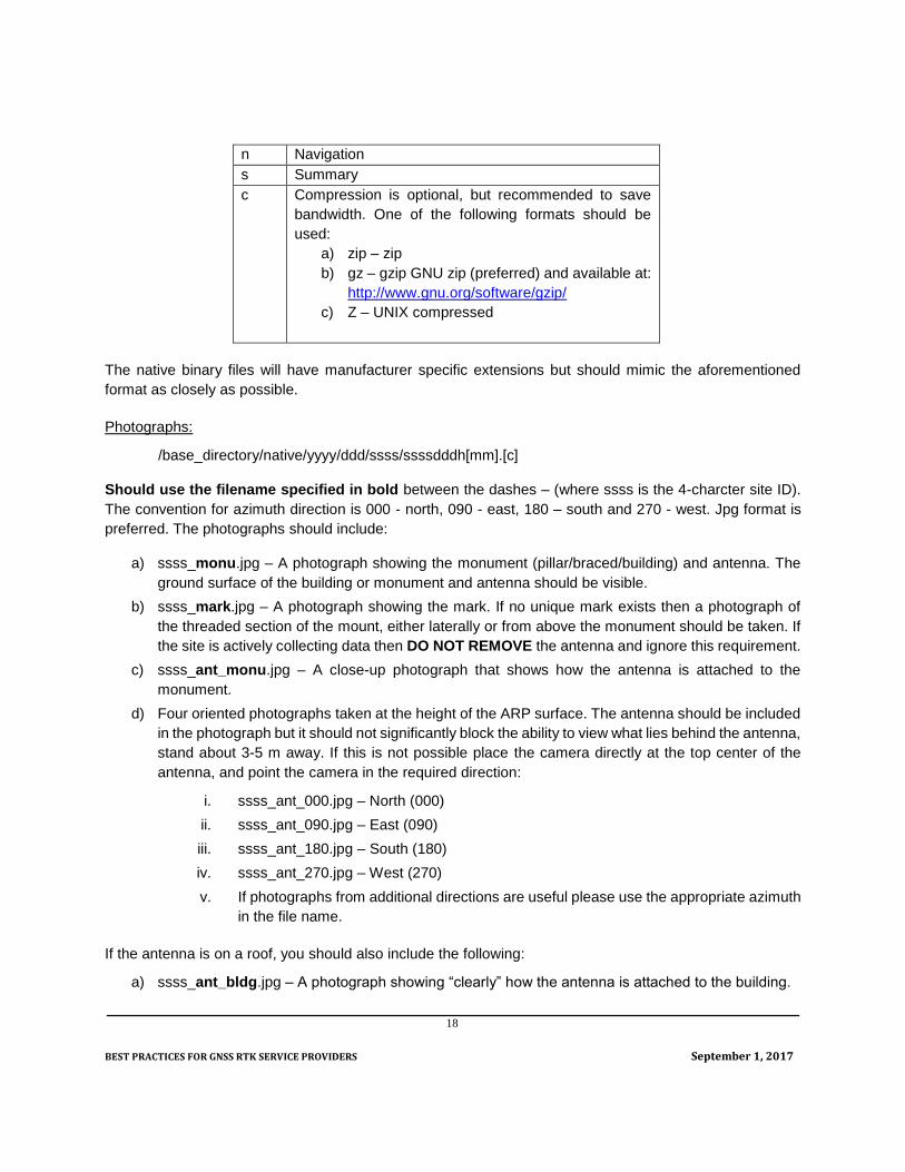
Photographs:
/base_directory/native/yyyy/ddd/ssss/ssssdddh[mm].[c]
Should use the filename specified in bold between the dashes – (where ssss is the 4-charcter site ID).
The convention for azimuth direction is 000 - north, 090 - east, 180 – south and 270 - west. Jpg format is
preferred. The photographs should include:
a) ssss_monu.jpg – A photograph showing the monument (pillar/braced/building) and antenna. The
ground surface of the building or monument and antenna should be visible.
b) ssss_mark.jpg – A photograph showing the mark. If no unique mark exists then a photograph of
the threaded section of the mount, either laterally or from above the monument should be taken. If
the site is actively collecting data then DO NOT REMOVE the antenna and ignore this requirement.
c) ssss_ant_monu.jpg – A close-up photograph that shows how the antenna is attached to the
monument.
d) Four oriented photographs taken at the height of the ARP surface. The antenna should be included
in the photograph but it should not significantly block the ability to view what lies behind the antenna,
stand about 3-5 m away. If this is not possible place the camera directly at the top center of the
antenna, and point the camera in the required direction:
i. ssss_ant_000.jpg – North (000)
ii. ssss_ant_090.jpg – East (090)
iii. ssss_ant_180.jpg – South (180)
iv. ssss_ant_270.jpg – West (270)
v. If photographs from additional directions are useful please use the appropriate azimuth
in the file name.
If the antenna is on a roof, you should also include the following:
a) ssss_ant_bldg.jpg – A photograph showing “clearly” how the antenna is attached to the building.
BEST PRACTICES FOR GNSS RTK SERVICE PROVIDERS September 1, 2017
19
b) ssss_ant_roof.jpg – A photograph showing the antenna and the roof surface.
c) ssss_ant_sn.jpg – A close-up photograph of the antenna showing its model and serial number.
d) ssss_rec_sn.jpg – A close-up photograph of the receiver showing its model and serial number.
e) ssss_rec.jpg – A photograph of the receiver location.
BEST PRACTICES FOR GNSS RTK SERVICE PROVIDERS September 1, 2017
20
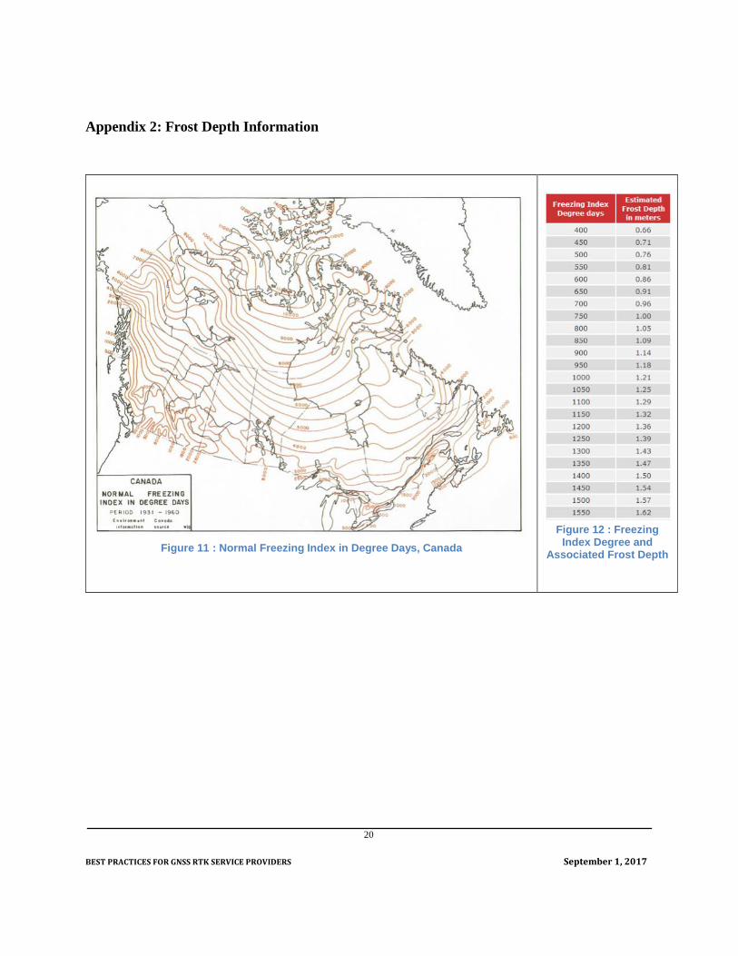
Appendix 2: Frost Depth Information
Figure 11 : Normal Freezing Index in Degree Days, Canada
Figure 12 : Freezing
Index Degree and Associated Frost Depth


![Common Ground Control Station for Unmanned Aerial Vehicle [UAV] Operation](https://static.fdocuments.net/doc/165x107/544bfa78af7959b0438b57a4/common-ground-control-station-for-unmanned-aerial-vehicle-uav-operation.jpg)


