GNSS Control Surveys
51
Guideline GNSS Control Surveys March 2020
Transcript of GNSS Control Surveys

Guideline GNSS Control Surveys March 2020

GNSS Control Surveys, Transport and Main Roads, March 2020
Copyright
© The State of Queensland (Department of Transport and Main Roads) 2020. Licence
This work is licensed by the State of Queensland (Department of Transport and Main Roads) under a Creative Commons Attribution (CC BY) 4.0 International licence. CC BY licence summary statement In essence, you are free to copy, communicate and adapt this work, as long as you attribute the work to the State of Queensland (Department of Transport and Main Roads). To view a copy of this licence, visit: https://creativecommons.org/licenses/by/4.0/ Translating and interpreting assistance
The Queensland Government is committed to providing accessible services to Queenslanders from all cultural and linguistic backgrounds. If you have difficulty understanding this publication and need a translator, please call the Translating and Interpreting Service (TIS National) on 13 14 50 and ask them to telephone the Queensland Department of Transport and Main Roads on 13 74 68.
Disclaimer While every care has been taken in preparing this publication, the State of Queensland accepts no responsibility for decisions or actions taken as a result of any data, information, statement or advice, expressed or implied, contained within. To the best of our knowledge, the content was correct at the time of publishing. Feedback Please send your feedback regarding this document to: [email protected]

GNSS Control Surveys, Transport and Main Roads, March 2020 i
Contents
1 Introduction ....................................................................................................................................1
1.1 Overview ......................................................................................................................................... 1
1.2 Key changes from version December 2016 and version March 2020 ........................................... 1
1.3 Network success – Get the planning and fieldwork right ................................................................ 2
1.4 Developing state-wide infrastructure .............................................................................................. 2
1.5 Purpose ........................................................................................................................................... 3
1.6 Associated Standards, Guidelines and Legislation ........................................................................ 3
1.7 Acronyms ........................................................................................................................................ 3
1.8 Definitions ....................................................................................................................................... 5
2 Project reference frame surveys ..................................................................................................8
2.1 Project reference frame marks ....................................................................................................... 8
2.2 Project life ....................................................................................................................................... 9
3 Survey datum .................................................................................................................................9
3.1 Geo reference system .................................................................................................................... 9
3.2 Connection to datum ..................................................................................................................... 10 3.2.1 Datum traceability ........................................................................................................ 10
3.3 Datum control................................................................................................................................ 10 3.3.1 Horizontal .................................................................................................................... 11 3.3.2 Vertical ......................................................................................................................... 11
3.4 Local AHD and ellipsoidal derived AHD heights ........................................................................... 12
4 Quantifying survey quality ......................................................................................................... 13
4.1 Uncertainty .................................................................................................................................... 13
4.2 Evaluating and expressing uncertainty ......................................................................................... 13
4.3 Survey control network uncertainty............................................................................................... 14
5 Equipment ................................................................................................................................... 14
6 GNSS methodology .................................................................................................................... 14
6.1 General considerations ................................................................................................................. 14
6.2 Project considerations .................................................................................................................. 15
6.3 Network considerations ................................................................................................................ 15
6.4 Mandatory observation practices .................................................................................................. 15 6.4.1 Epoch intervals ............................................................................................................ 16 6.4.2 Baselines ..................................................................................................................... 16 6.4.3 Photos ......................................................................................................................... 18
6.5 Default methodologies .................................................................................................................. 18 6.5.1 Dual occupations ......................................................................................................... 18 6.5.2 Dual 18+ hour static sessions ..................................................................................... 19 6.5.3 Combination methodology ........................................................................................... 19
6.6 Multi-Constellations and signal codes .......................................................................................... 20
7 Planning the network ................................................................................................................. 21
7.1 Safety ............................................................................................................................................ 21
GNSS Control Surveys, Transport and Main Roads, March 2020 ii
7.2 Network design ............................................................................................................................. 21 7.2.1 Research original marks and surveys ......................................................................... 22 7.2.2 GNSS for ellipsoidal heights ........................................................................................ 23 7.2.3 GNSS for AHD heights ................................................................................................ 23 7.2.4 Property access ........................................................................................................... 23 7.2.5 Choose methodology .................................................................................................. 23
7.3 Reconnaissance ........................................................................................................................... 24
7.4 Placing new marks ........................................................................................................................ 25
7.5 Field observation schedule ........................................................................................................... 25 7.5.1 GNSS Planning ........................................................................................................... 25 7.5.2 Review network design and methodology ................................................................... 25 7.5.3 Create field observation schedule ............................................................................... 26
8 Fieldwork – session observations ............................................................................................ 26
8.1 Safety ............................................................................................................................................ 26
8.2 Preparation ................................................................................................................................... 27
8.3 Setup ............................................................................................................................................. 27 8.3.1 Antenna orientation ..................................................................................................... 27 8.3.2 Observation records .................................................................................................... 28 8.3.3 Photos ......................................................................................................................... 29
8.4 Download data .............................................................................................................................. 32
9 Processing and adjustment ....................................................................................................... 33
9.1 Epoch interval ............................................................................................................................... 33
9.2 Daily check processing ................................................................................................................. 33
9.3 Baseline processing ...................................................................................................................... 33
9.4 Network adjustment ...................................................................................................................... 33 9.4.1 Minimally constrained adjustment ............................................................................... 33 9.4.2 Constrained adjustment .............................................................................................. 33
9.5 Uncertainty calculation .................................................................................................................. 34 9.5.1 12d Model macro ......................................................................................................... 34 9.5.2 Spreadsheet ................................................................................................................ 35
10 Reports and deliverables ........................................................................................................... 35
Appendix A – GNSS Network Workflow ............................................................................................ 37
Appendix B – GFM methodology flowchart ...................................................................................... 38
Appendix C – Observation record example ...................................................................................... 39
Appendix D – Network examples ....................................................................................................... 41

GNSS Control Surveys, Transport and Main Roads, March 2020 1
1 Introduction
1.1 Overview
This GNSS Control Surveys document is a guideline for the specific requirements for the planning, observation and delivery of Project Reference Frame surveys using Global Navigation Satellite System (GNSS) technology for the Department of Transport and Main Roads. It aims to bring consistent methodology and understanding of the department’s current capture and adjustment requirements for GNSS surveys for project control.
This version replaces GNSS Control Surveys (December 2016). New versions of the Intergovernmental Committee on Surveying and Mapping’s peak control survey document, Standards for the Australian Survey Control Network – Special Publication 1 have also been published (current version 2.1) which feature new standards and guidelines.
For detailed baseline processing and network adjustment procedure, refer to the department’s Trimble Business Center v5.0 – Processing and Adjusting GNSS Control Networks, October 2019 manual (or its successor).
1.2 Key changes from version December 2016 and version March 2020
• Mandatory dual sessions. Dual sessions provide two main purposes which are:
− Loop closures - For loop closures to be performed, GNSS baselines are required from more than one observation session. If only one session is used, the baselines are correlated (have at least one common source of error) and thus, the loop closures will tend to always indicate misleading excellent results. In addition, by having several of the points being occupied on more than one occasion will aid in detecting whether antenna height mistakes are present in the data set.
− Redundancy - Redundancy provides blunder detection such as mis-measurement of antenna heights and re-cantering errors. In addition, the ranges between the satellites and the receivers defining the baselines will be from different constellations at different times.
• Independent baselines only for network adjustments. Including dependent baselines introduce false redundancy in sample size (Degrees of Freedom) and will inflate the accuracy in the minimally constrained adjustment. They will make it easier to pass the Chi square test and thus give a misleading pass result.
• Observation times - Longer observation time reduces random error. There are different observation times depending on purpose:
− Primary purpose – To provide a Project Reference Frame to suit Transport and Main Roads project requirements. Minimum observation time is 1 hour plus 5 minutes per 1 km of baseline length. NOTE: Observation times more than 1 hour require 30 second epoch intervals.
− Secondary purpose – For submitting GNSS observed data to the Department of Natural Resources, Mines and Energy (DNRME) for inclusion into the State-wide datum adjustment. Minimum observation time is 6 hours.

GNSS Control Surveys, Transport and Main Roads, March 2020 2
• Horizontal Survey Uncertainty (SU) resultant coordinates of Project Reference Frame marks values have been amended from <10 mm to <15 mm. The value of <10 mm was based on the practice of including dependent baselines in a minimally constrained network adjustment. This introduces false redundancy in sample size (Degrees of Freedom) and inflates the accuracy in the minimally constrained adjustment.
1.3 Network success – Get the planning and fieldwork right
The most crucial contributing elements to the success of any GNSS control network project are the recording of good quality satellite data for sufficient length of time, with connections to high quality datum control survey marks.
Selecting good sites with minimal obstructions and recording longer sessions than is theoretically required will generally produce good quality results. Good quality long session data will generally process and adjust easily and quickly.
KEY POINT
No amount of manipulation of the data during the processing and adjustment phase can make up for lack of good data, poor planning or field craft. Common causes of network failure are insufficient session lengths, poor quality datum marks used, using marks with satellite visibility problems (obstructions & multipath) and an insufficient number of baselines observed. Short cuts will lead to failures and re-work.
1.4 Developing state-wide infrastructure
As a state government department, Transport and Main Roads have an obligation to contribute to the development of state-wide infrastructure as well as datum propagation and improvement. Project control should not be looked at in isolation, it is part of a much bigger picture.
Furthermore, surveys for the department are of value for a survey and mapping infrastructure purpose, and therefore are subject to the conditions contained in the Surveying and Mapping Infrastructure Act 2003 and Surveying and Mapping Infrastructure Regulation 2014.
The Survey and Mapping Infrastructure Regulation 2014 states that:
A survey is of value for a survey and mapping infrastructure purpose if, for example, the survey:
• produces information in a form that can be recorded in a state dataset,
• places permanent marks,
• makes measurements between permanent marks, and
• makes measurements that establish the relationship between the geodetic reference framework and a subsidiary framework (example of a subsidiary framework – cadastral boundary system)
Surveys of value to surveying and mapping infrastructure must be carried out in a way that achieves the survey's intended purpose. The survey's intended purpose may be achieved by, for example:
• establishing appropriate survey marks for the survey by:
− placing survey marks of a type complying with the relevant survey standard, and
− using existing survey marks as reference points.

GNSS Control Surveys, Transport and Main Roads, March 2020 3
• depicting in the survey record, the spatial location and extent of the features surveyed as required by an established survey standard, and
• achieving an acceptable level of survey quality that is appropriate for the survey's intended purpose as required by an established survey standard.
1.5 Purpose
Primary purpose: To provide a Project Reference Frame (Survey Control) to suit Transport and Main Roads project requirements. Minimum observation time is 1 hour plus 5 minutes per 1 km of baseline length. NOTE: Observation times of 1 hour or more require 30 second epoch intervals.
However, it is strongly recommended to adopt the preferred methodology of a minimum of dual 6 hours session lengths for submitting GNSS observed data to the Department of Natural Resources, Mines and Energy (DNRME) for inclusion into the State-wide datum adjustment. See Section 1.4
Secondary purpose: For submitting GNSS observed data to the Department of Natural Resources, Mines and Energy (DNRME) for inclusion into the State-wide datum adjustment. Minimum observation time is 6 hours.
1.6 Associated Standards, Guidelines and Legislation
Users of this manual should be familiar with the Intergovernmental Committee on Surveying and Mapping’s publication Standard for Australian Survey Control Network – Special Publication (SP1) V2.1 and associated Guideline documents. For GNSS Control surveys, the most relevant guideline documents can include:
• Guideline for Control Surveys by GNSS V2.1
• Guideline for Adjustment and Evaluation of Survey Control V2.1
• Guideline for Installation and Documentation of Survey Control Marks V2.1
• Guideline for Continuously Operating Reference Stations V2.1
• Standard for the Australian Survey Control Network – SP1 Version 2.1
Users should also be familiar with relevant sections contained within Transport and Main Roads surveying standard:
• TMR Surveying Standards (February 2016)
Users should also be familiar with relevant sections contained within:
• Survey and Mapping Infrastructure Act 2003
− Survey and Mapping Infrastructure Regulation 2014
1.7 Acronyms
The following abbreviations have been used throughout this document.
AHD Australian Height Datum (1971)
ALS Airborne Laser Scanning

GNSS Control Surveys, Transport and Main Roads, March 2020 4
ANJ Queensland State Adjustment (State Control Survey) comprising Asia-Pacific Reference Frame (APREF), National GNSS Campaign Archive (NGCA) administered by Geoscience Australia and Jurisdictional Data Archive (JDA) administered by Queensland Department of National Resources, Mines and Energy (DNRME)
ARP Antenna Reference Point
AUSGeoid AUSGeoid models are used to convert ellipsoidal heights to Australian Height Datum (AHD) and vice versa
AUSPOS Online GPS processing service provided by Geoscience Australia
CORS Continuously Operating Reference Station
DCS Datum Control Survey
DER Permanent Mark Detailed Enquiry Report
DNRME Department of Natural Resources, Mines and Energy
GA Geoscience Australia
GDA2020 Geocentric Datum of Australia 2020
GDA94 Geocentric Datum of Australia 1994
GFM Ground and feature model survey
GIS Geographic Information System
GLONASS Global Navigation Satellite System (Russian Federation)
GNSS Global Navigation Satellite System
GPS Global Positioning System (USA)
GRS80 Geodetic Reference System 1980 reference ellipsoid
ICSM Intergovernmental Committee on Surveying & Mapping
ITRF International Terrestrial Reference Frame
MGA2020 Map Grid of Australia 2020
MGA94 Map Grid of Australia 1994
MLS Mobile Laser Scanning
NGRS National Geospatial Reference Frame
NGS National Geodetic Survey (USA)
NLN National levelling network
NRTK Network Real Time Kinematic Global Navigation Satellite System
PRF Project Reference Frame
PRFM Project Reference Frame Marks
PM Permanent Mark

GNSS Control Surveys, Transport and Main Roads, March 2020 5
PU Positional Uncertainty
RTK Real Time Kinematic Global Navigation Satellite System
RU Relative Uncertainty
SBQ Surveyors Board of Queensland
SCDB Survey Control Database
SP1 ICSM Standard for the Australian Survey Control Network, Special Publication 1, v2.1, October 2014
SU Survey Uncertainty
UTM Universal Transverse Mercator projection
WGS84 World Geodetic System 1984
1.8 Definitions
AUSGeoid09
AUSGeoid09 is a 1’ by 1’ (approximately 1.8 km) grid used to transfer heights between the ellipsoid (GDA94) and the Australian Height Datum (AHD). Unlike previous versions of AUSGeoid (‘93/’98), AUSGeoid09 provides users with the height offset between the ellipsoid and AHD as opposed to the ellipsoid and the geoid.
AUSGeoid2020
"Onshore, AUSGeoid2020 is a combined gravimetric-geometric model. The gravimetric component is a 1' by 1' grid of ellipsoid-quasigeoid separation values created using data from gravity satellite missions (e.g., GRACE, GOCE), re-tracked satellite altimetry, localised airborne gravity, land gravity data from the Australian national gravity database and a Digital Elevation Model to apply terrain corrections.
The geometric component is a 1' by 1' grid of quasigeoid-AHD separation values and is developed using a dataset of collocated GNSS ellipsoidal height and AHD heights. The geometric component attempts to account for an offset between AHD and the quasigeoid that ranges from about -0.5 m (AHD below quasigeoid) in the southwest of Australia to about +0.5 m (AHD above quasigeoid) in the northeast of Australia. The offset between AHD and the quasigeoid is primarily due to the method by which AHD was realised. Given that the warmer, less dense water off the coast of northern Australia is approximately one metre higher than the cooler, denser water off the coast of southern Australia, by constraining each of the tide gauges to zero AHD, the effects of sea surface topography were propagated into the adjustment.
Differences between AUSGeoid09 and AUSGeoid2020
Aligned with GDA2020
The change in the reference frame used for the development of GDA2020 (i.e. ITRF2014 compared to ITRF92 used for GDA94) means the ellipsoidal height of a point in GDA94 is approximately 9 cm higher than GDA2020. As a result, AUSGeoid2020 is incompatible with GDA94. Data referenced to GDA94 is only compatible with AUSGeoid09.

GNSS Control Surveys, Transport and Main Roads, March 2020 6
Uncertainty provided
AUSGeoid09 provided an estimate of the root mean square error at the input data points used in the construction of the model (Brown et al., 2011). AUSGeoid2020 provides a rigorous uncertainty value associated with the offset between the ellipsoid and AHD, varying as a function of location. This value includes the uncertainty from the gravimetric component and geometric component of the model." Geocentric Datum of Australia 2020 Technical Manual 56 Version 1.3.
Australian Height Datum (AHD)
Australian Height Datum is the national height datum surface based on mean sea level for 1966-1968 at 30 tide gauges around Australia, adopted by the National Mapping Council in 1971 (AHD71) as the datum to which all vertical control for mapping is to be referred.
Australian Height Datum Derived (AHDD)
Heights derived relative to the Australian Height Datum.
Australian Height Datum Derived (AHDD) – Local
Local AHD refers to AHD heights that have been transferred by differential levelling.
Australian Height Datum Derived (AHDD) – AUSGeoid derived
AHD heights that have been derived from GNSS observations using AUSGeoid separation values.
Datum
A set of parameters which define the origin and orientation of a reference system with respect to a fundamental absolute system.
Datum Control Surveys
These surveys define, extend or improve the National Geospatial Reference System (NGRS). These control surveys are included in NGRS adjustments to allow for the most rigorous estimation and testing of position and uncertainty for new and existing survey control marks in the NGRS (see SP1). Realised as Datum marks within DNRME’s Survey Control Database (SCDB).
Datum Control Surveys
Datum Control Survey marks realised as Datum marks within DNRME’s Survey Control Database (SCDB).
Ellipsoidal heights
Global positioning, such as GNSS, will generally give a latitude, longitude (or x and y position) and height. This height is usually the height above (or below) the ellipsoid (spheroid).
Geocentric Datum of Australia 2020 (GDA2020)
An ellipsoidal surface expressed as latitudes and longitudes which has its origin at the centre mass (hence the term Geocentric) of the earth. The coordinate datum of the GDA2020 is the Australian Fiducial Network (AFN), which is tied to the International Earth Rotational Reference System (IERS) Terrestrial Reference Frame 2014 (ITRF2014), epoch 2020.0

GNSS Control Surveys, Transport and Main Roads, March 2020 7
Geocentric Datum of Australia 1994 (GDA94)
An ellipsoidal surface expressed as latitudes and longitudes which has its origin at the centre mass (hence the term Geocentric) of the earth. The coordinate datum of the GDA’94 is the Australian Fiducial Network (AFN), which is tied to the International Earth Rotational Reference System (IERS) Terrestrial Reference Frame 1992 (ITRF92), epoch 1994.0.
Geoid
The equipotential surface of the Earth’s gravity field which best fits global mean sea level.
Map Grid of Australia 2020 (MGA2020)
Cartesian coordinates from a universal transverse Mercator projection based on the Geocentric Datum of Australia 2020 (GDA2020) latitudes and longitudes.
Map Grid of Australia 1994 (MGA94)
Cartesian coordinates from a universal transverse Mercator projection based on the Geocentric Datum of Australia 1994 (GDA94) latitudes and longitudes.
National Geospatial Reference Frame (NGRS)
The National Geospatial Reference System is Australia’s high accuracy spatial referencing system. It includes GDA94 and AHD71.
NLN
National Levelling Network heights are the highest accuracy and most rigorously derived height. Marks in the NLN usually have Class A 1st Order or Class C 3rd Order heights. Some NLN runs only featured one way levelling and therefore have Class D 4th Order heights.
Permanent Survey Mark (PSM) or Permanent Mark (PM)
Permanent survey marks or Permanent marks form part of the state’s survey and mapping infrastructure and are maintained within the survey control register (SCDB) by DNRME.
Project
A specific activity which creates and delivers a unique product or service.
Project Reference Frame (PRF)
A Reference Frame or Framework for a specific project.
Project Reference Frame Marks (PRFM)
The Survey control marks that create the Project Reference Frame, these marks will be fit for purpose and provide a valid coordinate within the PRF.
Reference Framework
Provides a reference from which measurements can be taken so that it is possible to define positions in space in either zero, one, two or three dimensions. They can be represented by Survey Control marks which are usually physically established marks on the ground in the form of permanent marks.

GNSS Control Surveys, Transport and Main Roads, March 2020 8
SP1
ICSM - The Standard for the Australian Survey Control Network – Special Publication 1 (v2.1) and associated Guidelines provide an outcomes based framework that supports the highest level of rigour and integrity in the delivery and maintenance of Australia’s survey control mark network.
Standards
TMR Surveying Standards February 2016 (Part 1, Part 2 & Schedule 1)
Uncertainty
Uncertainty in these Standards is as defined and realised as per SP1. It is the doubt about the validity of a measurement or result of a measurement (for example, a coordinate). It is an indication of how wrong a value may be and is used in these Standards to quantify the level of survey quality. Uncertainty is expressed as a standard of deviation in the International System of Units (SI) expanded to the 95% confidence level.
2 Project reference frame surveys
The Project Reference Frame (PRF) is a Reference Frame or Framework for a specific project. The PRF defines the position of a project as evidenced by the coordinates of the Project Reference Frame Marks (PRFM). PRFM’s are the primary survey control for a project.
A Project Reference Frame shall be used to define the position of the project for the following geomatic survey types:
• Total Station and RTK GNSS Ground and Feature Model (GFM) – generally 1 km spaced PM’s
• Photogrammetry GFM – the PM’s covering the project extents that are used to coordinate the ground control targets
• Airborne Laser Scanning GFM – the PM’s used as control
• Mobile Laser Scanning GFM – the PM’s used as control
• Terrestrial Laser Scanning GFM – generally 1 km spaced PM’s
• Construction – generally the PRF 1 km spaced control marks from the GFM, and
• Audit – generally the PRF from the GFM and the major survey marks from the construction phase.
2.1 Project reference frame marks
Project Reference Frame Marks (PRFM) create the Project Reference Frame and are the primary onsite horizontal and vertical coordinate reference marks for each survey project. These marks will be coordinated using datum control PM’s that meet the position quality (≤ 0.020 m) required by the TMR Surveying Standards February 2016, Part 2, Section 1.3.1.1.
The PRF will primarily consist of existing or newly placed PM’s and will comprise of a minimum of three marks for every project. Ideally, they should be positioned such that they encompass the project. Survey marks shall meet the requirements of the TMR Surveying Standards February 2016 Part 1 Section 6 for PM’s.
PRF requirements may vary for different geomatic survey types and will be stated in the relevant survey type sections of the TMR Surveying Standards or the Survey Brief.

GNSS Control Surveys, Transport and Main Roads, March 2020 9
Care must be taken when choosing or placing PRFM’s to ensure they won’t be disturbed and will be useful and relevant for the entire life of the project, that is until the project has been constructed and audited. There shall be a minimum spacing of 500 m between PRFM’s.
For smaller projects, like an intersection survey, these requirements may be varied in the Survey Brief.
KEY POINT
Be aware that extra care must be taken with the fieldwork as baselines under 500 m often lead to processing and adjustment failures as well as failing to meet uncertainty requirements.
Consideration should be given to positioning the primary control outside of the project limits as these reduce the likelihood of disturbance by the construction phase, increases GNSS baseline lengths and increases total station sight distances.
2.2 Project life
When defining the Project Reference Frame, the requirements of the entire life of the project should be considered. Appropriately positioned and spaced PRFM’s can be used from the planning stage through to pre-design, construction and audit phases which may span over many years. Densification of the PRF for the different project stages is easily achievable by not having to re-occupy remotely located Datum Control Survey marks, which saves time and money.
For example, creation of a PRF for a 30 km long photogrammetry project. Place PRFM’s at 5 km intervals across the project extents in safe positions (considering any new concept alignments). Photogrammetry ground control marks are coordinated from PRFM’s. A subsequent pre-design total station GFM would densify the 5 km spaced PRF down to a 1 km spaced PRF by using the PRFM’s as control. Construction and audit phases would use the 1 km spaced PRF as the basis for the respective survey components.
3 Survey datum
Survey Datum is the framework upon which all geospatial information, including the PRF is referenced. The Survey Datum not only supports the accuracy of captured survey data, but also provides geospatial correlation with other data sets. It determines the integrity of delivered geospatial products and is the core element for sharing geospatial information within the department, other agencies in the Government and the private sector. The departments specified Datum’s are listed in the TMR Surveying Standards.
3.1 Geo reference system
The Geo reference system is a three-dimensional reference framework that consists of a mathematical system where geometric parameters define the size, shape and location of a reference ellipsoid/spheroid surface. It is a closed geometric shape that is an approximate mathematical shape of the earth which for a Geocentric datum has its origin at the centre mass of the earth. GDA94 and GDA2020 are a geo reference system.
GNSS Control Surveys, Transport and Main Roads, March 2020 10
KEY POINT
Unless specified otherwise, GDA2020 has not yet been adopted by Transport and Main Roads. With the implementation of Geocentric Datum of Australia 2020 (GDA20200), Geoscience Australia is updating Regulation 13 Certificates on Continually Operating Reference Stations (CORS) survey marks to be published as GDA2020 coordinate values.
As many current projects are based on GDA94, it will be necessary to undertake a coordinate transformation from GDA2020 to GDA94 from the GDA2020 published values. The Intergovernmental Committee on Surveying and Mapping (ICSM) has published a technical manual (Geocentric Datum of Australia 2020 Technical Manual) from the ISCM website https://www.icsm.gov.au/publications/gda2020-technical-manual-v-12 that provides descriptions and transformation parameters to assist with datum transformation between GDA2020 to GDA94.
Transport and Main Roads has also published a document “Transformations from GDA2020 to GDA94” is located at the following link:
https://www.tmr.qld.gov.au/business-industry/Technical-standards-publications/Surveying-support-documents
3.2 Connection to datum
The Project Reference Frame shall be coordinated relatively to the departments specified Datum’s. These origin datum marks are referenced within Queensland by PM’s (including CORS) in DNRME’s Datum Control Survey’s. This survey control mark network is maintained as the Survey Control Database (SCDB) and is easily found in the Queensland Globe. To rigorously propagate datum to the PRF, direct measurements to the Datum Control Survey mark network are required.
3.2.1 Datum traceability
Datum Control Survey points must be clearly annotated and referenced within the deliverable survey information. This traceability shall include datum origin information, values adopted and a copy of the originating documents. DNRME are currently re-adjusting the ANJ network every month which means traceability of the origin of survey is critically important. Looking to the future, the implementation of a dynamic datum in Australia will necessitate keeping comprehensive records for traceability.
3.3 Datum control
Datum Control Survey marks of sufficient quality within the Survey Control Database (SCDB) of Permanent Marks (PM) administered by the Department of Natural Resources and Mines (DNRME) shall be the origin of the PRF. Only marks that meet the criteria in Section’s 3.2.1 and 3.2.2 shall be used as datum control. Only the Project Manager can vary this requirement. For example, when joining to an existing survey or in remote areas where only survey marks with larger PU than required are available.
In addition to the position quality requirements presented below, the quality of the physical mark including stability, and proximity to the project site must also be considered.

GNSS Control Surveys, Transport and Main Roads, March 2020 11
3.3.1 Horizontal
A minimum of three horizontal datum control marks shall be connected to in every survey control network. Datum Control marks to derive horizontal coordinates of the PRFM network shall have a horizontal Positional Uncertainty of ≤ 0.020 m. The use of CORS is highly desirable as they have a horizontal PU of close to 0.010 m, are usually very stable and highly repeatable.
A hierarchical system shall be used when selecting Datum Control PM’s based on GDA94 horizontal uncertainty. In descending order of desirability:
i. Tier 1 and 2 Continuously Operating Reference Stations (CORS) with Regulation 13 Certificate (see SP1 v2.1 – Guideline for Continuously Operating Reference Stations, Sections 3.1 and 3.2)
ii. Tier 3 Continuously Operating Reference Stations (CORS) with Regulation 13, (see SP1 v2.1 – Guideline for Continuously Operating Reference Stations, Sections 3.1 and 3.2), and
iii. ANJ (Queensland ANJ Adjustment) PM’s with PU ≤ 0.020 m.
KEY POINT
Whilst GDA2020 is discussed throughout this document, it has not been adopted as datum by Transport and Main Roads at the date of this publication. GDA94 remains the current datum reference to be adopted.
3.3.2 Vertical
The requirements to reference vertical datum control marks needs to be assessed on a project by project basis. Some projects may not require a high level of attention to vertical datum when observing the GNSS network as all marks will be subsequently differentially levelled from a local vertical datum mark. All networks shall connect to at least one good quality vertical datum mark.
Therefore, the height quality of PM’s used as datum to derive height on PRFM’s is partially dependant on the intended use of the derived heights. When heights are required, a minimum of three vertical datum control points shall be connected to.
A hierarchical system shall be used when selecting PM’s to derive the height of PRFM’s. The system is based on GDA94 ellipsoidal vertical uncertainty and AHD quality. In descending order of desirability, with option iv) representing the minimum acceptable level of quality to be used:
i. ANJ PM’s with Ellipsoidal PU ≤ 0.050 m and AHD 3rd Order Class C quality
ii. AHD 3rd Order Class C quality PM’s
iii. ANJ PM’s with Ellipsoidal PU ≤ 0.050 m and AHD 4th Order (minimum Class D) quality, and
iv. AHD 4th Order (minimum Class D) quality PM’s.
GNSS Control Surveys, Transport and Main Roads, March 2020 12
3.4 Local AHD and ellipsoidal derived AHD heights
Default height datum for departmental surveys is AHD71. Heights on Datum Control marks may be:
• AHD or AHDD derived by differential levelling
• AHDD derived from ellipsoidal height with a separation value applied from AUSGeoid09
• Ellipsoidal height, and
• No AHD height.
AHD heights derived using a different Geoid model version to the project shall NOT be used as height datum (constrained in the network adjustment) for the project.
(For example: an AUSGeoid98 derived AHD height shall NOT be used as datum on an AUSGeoid09 project. Nor should an AUSGeoid09 derived AHD height be used as datum on an AUSGeoid2020 project).
Users of GNSS techniques need to be aware of the differences that can exist between heights derived by the different methods.
CORS marks have very high quality ellipsoidal heights but may exhibit differences to local NLN / AHDD heights when compared. This can be due to regional uncertainties in the geoid model and inaccuracies in the levelled network. The differences can be significant with many areas exhibiting a difference of 50 to 100 mm between local AHD and AHD derived from ellipsoid heights using AUSGeoid09. The objective of the GNSS network with regards to height needs to be considered when choosing marks for height with either ellipsoidal, AUSGeoid09 derived AHD or spirit levelled AHD heights.
KEY POINT
When performing a least squares network adjustment, it is highly recommended that ellipsoidal heights (or ellipsoidal derived AHD) and local AHD heights are NOT both constrained in the same adjustment. Generally, the network will not process well or produce high quality adjustment results.
Early in the project planning stage, it should be decided what the GNSS derived heights will be used for and if ellipsoidal or local AHD heights will be constrained.
KEY POINT
Unless specified otherwise, AUSGeoid2020 has not yet been adopted by Transport and Main Roads.
WARNING: AUSGeoid09 is aligned with GDA94 and AUSGeoid2020 is aligned with GDA2020. As there is an approximate 9 cm height difference between the GDA94 and GDA2020 ellipsoids, never use AUSGeoid2020 with GDA94 or AUSGeoid09 with GDA2020. They are incompatible with each other.

GNSS Control Surveys, Transport and Main Roads, March 2020 13
4 Quantifying survey quality
The ICSM Standard for the Australian Survey Control Network - SP1 v2.1 is to be used as the basis to the minimum requirements for determining position and associated uncertainty for survey control networks. SP1 v2.1 completes the transition from CLASS and ORDER to uncertainty as the basis for evaluating and expressing the quality of measurements and positions.
The purpose of the SP1 standard is “to specify the minimum requirements for the determination of one, two, or three dimensional position and associated uncertainty of Australia’s survey control marks”.
4.1 Uncertainty
SP1 states:
“The quality of a control survey shall be quantified in terms of uncertainty. When quantifying survey quality, the following uncertainty categories shall apply:
Survey Uncertainty (SU) is the uncertainty of the horizontal and/or vertical coordinates of a survey control mark relative to the survey in which it was observed and is free from the influence of any imprecision or inaccuracy in the underlying datum realisation. Therefore, SU reflects only the uncertainty resulting from survey measurements, measurement precisions, network geometry and the choice of constraint. A minimally constrained least squares adjustment is the preferred and most rigorous way to estimate and test SU. SU is expressed in SI units at the 95% confidence level.
Positional Uncertainty (PU) is the uncertainty of the horizontal and/or vertical coordinates of a survey control mark with respect to the defined datum and represents the combined uncertainty of the existing datum realisation and the new control survey. That is, PU includes SU as well as the uncertainty of the existing survey control marks to which a new control survey is connected. A fully constrained least squares adjustment is the preferred and most rigorous way to estimate and test PU. PU is expressed in SI units at the 95% confidence level.
Relative Uncertainty (RU) is the uncertainty between the horizontal and/or vertical coordinates of any two survey control marks. Such marks may be connected by measurement directly or indirectly. The preferred and most rigorous means for deriving RU between pairs of marks is by propagating the respective variances and co-variances obtained from a minimally or fully constrained least squares adjustment (i.e. from SU or PU). RU can be expressed in SI units at the 95% confidence level, or in a proportional form such as a ratio of uncertainty per unit length or survey misclosure.”
4.2 Evaluating and expressing uncertainty
SU shall be estimated as per Section A3.4 of the Addendum of Transport and Main Road’s Trimble Business Center v5.0 – Processing and Adjusting GNSS Survey Control Networks manual, October 2019.
PU shall be estimated as per Section A3.4 of the Addendum of Transport and Main Road’s Trimble Business Center v5.0 – Processing and Adjusting GNSS Survey Control Networks manual, October 2019.
SU and PU of Survey Control shall be expressed in terms of a horizontal circular confidence region at the 95% confidence interval.
The department’s intention is for project calculated uncertainty values to closely resemble ANJ state-wide adjustment uncertainty values after the Transport and Main Roads network has been included.
GNSS Control Surveys, Transport and Main Roads, March 2020 14
4.3 Survey control network uncertainty
The resultant coordinates of Project Reference Frame marks shall meet a horizontal Survey Uncertainty (SU) of < 0.015 m and an estimated Horizontal Positional Uncertainty (PU) of ≤ 0.030 m (see TMR Surveying Standards, February 2016, Part B Section 5.3.3).
KEY POINT
Applying uncertainty values of existing survey control marks in a constrained adjustment is defined in Clause 4 of the Standard for the Australian Survey Control Network – SP1 Version 2.1 as “…PU includes SU as well as the uncertainty of the existing survey control marks to which a new control survey is connected. A fully constrained least squares adjustment is the preferred and most rigorous way to estimate and test PU. PU is expressed in SI units at the 95% confidence level”
Adherence to this requirement is specified in Section 5.2 of the TMR Surveying Standards, Part 2, February 2016 as “…Control surveys undertaken for TMR shall be based on SP1 guidelines.”
The Positional Uncertainty (PU) values published at 95% uncertainty for existing survey control marks shall be applied as a weighting expressed at one sigma uncertainty in a constrained least squares adjustment in the department’s Trimble Business Center v5.0 – Processing and Adjusting GNSS Control Networks, October 2019 manual
5 Equipment
GNSS and ancillary equipment shall meet the following minimum requirements:
• GNSS receiver shall be capable of dual frequency code and carrier phase tracking
• GNSS antenna shall be of survey quality
• GNSS antenna model shall have a NGS or IGS absolute calibration, and
• Tripod, tribrach and plummet shall be of high quality and in good adjustment (within equipment manufacturers stated precisions).
6 GNSS methodology
Two GNSS methods are supported for determination of a Project Reference Frame for the department. These methods are Classic Static (also known as Static) and Rapid Static (also known as Fast Static and Quick Static).
Post Processed Kinematic (PPK), Real Time Kinematic (RTK) and Network RTK (NRTK) are not supported and are unacceptable to coordinate PRFM’s.
6.1 General considerations
Rapid Static and Classic Static GNSS networks are the most accurate, rigorous and reliable methods for coordinate definition and subsequent evaluation of uncertainty of project survey control.
The influence of internal and external effects should be minimised by good site selection and network planning. Typical factors affecting GNSS measurements are (see SP1):
• GNSS system effects such as the ephemeris error and satellite availability and geometry at each survey site.
• Atmospheric effects due to the ionosphere and troposphere.

GNSS Control Surveys, Transport and Main Roads, March 2020 15
• Site dependant effects such as obstructions, multipath and interference from non-GNSS radio sources, and
• Instrumental effects, un-modelled antenna centre phase offsets.
Well accepted methods for minimising errors due to these effects are:
• Redundancy in the observations
• absence of signal obstructions, and
• longer observation session duration.
Effects external to the GNSS measurements should be eliminated by incorporating procedures for minimising blunders such as checking mark identifiers, centring and orientation of the antenna, and the measurement of antenna heights (see also Section 8.3.3 photos).
6.2 Project considerations
The requirements of the project reference frame need to be assessed to determine the GNSS network methodology to be used. A number of factors need to be considered, including:
• The purpose of the project reference frame. Type of survey the PRF will or may be used for
• is the purpose to determine horizontal coordinates; or horizontal coordinates and vertical heights
• the required quality of resultant positions including future project use
• value and use of the project reference frame over the life of the project (not just the immediate use), and
• value to the state-wide infrastructure.
6.3 Network considerations
There are some basic network questions that need to be considered for every project to help determine the appropriate methodology.
• Required quality level on resultant PRF survey marks (SU & PU)
• density of existing ANJ marks with ≤ 0.020 m horizontal positional uncertainty
• baseline lengths, and
• spacing of project reference frame marks.
6.4 Mandatory observation practices
The following observation practices are mandatory regardless of the overall methodology unless specified differently in the Survey Brief.
• Satellite elevation mask set to 10° above horizontal for field sessions.
• Antenna orientated to within 5°of true north (see NGS website for antenna information & Section 8.3.1 of this guideline).
• Minimum observation session length shall be 1 hour plus 5 minutes per 1 km of baseline length.

GNSS Control Surveys, Transport and Main Roads, March 2020 16
• Occupations of the same mark shall be separated by a minimum of 30 minutes between the end of one session and the start of the subsequent session (unless restarting due to an unplanned event like battery failure). This is to allow some change in the satellite configuration.
• The tripod must be reset with the reference height varied by a minimum of 0.1 m between occupations.
• Instrument height measurements are to be independently verified at start and end of occupation.
• Validation photos shall be taken of all session setups (see Section 8.3.3).
• A minimum of three datum control survey marks will be observed as part of the network.
• A minimum of three PRFM’s (excluding datum control marks unless they are inside the project extents) shall form the PRF.
• Networks should feature sufficient redundancy, closed figures and no single radiations, and
• Employ good network design – do not extrapolate, the PRF is to be contained within the datum control used.
6.4.1 Epoch intervals
It is vitally important that the epoch logging interval is set correctly and consistently across all GNSS receivers utilised on the project. Setting a large epoch interval for a short session will result in less observations recorded than desirable which may negatively affect the accuracy. Setting too small of an interval for a long session will result in too many observations being recorded with little satellite configuration change.
• Networks adopting a methodology of observation sessions of 1 hour and more are to record at epoch intervals of 30 seconds or less but must process at 30 seconds.
KEY POINT
To limit the necessity of changing epoch record intervals in the receivers, an epoch interval that is compatible with both methods may be set for the field recording sessions, however data shall be processed at the epoch intervals stated above. Rinex files shall only include data at the epoch record intervals required above.
6.4.2 Baselines
Ideally every possible baseline between the chosen network marks, both datum control and PRFM’s, should be observed for as long as possible. As this is not always possible or practical, the following rules have been developed and shall be adhered to as the minimum required. Some projects may require additional baselines due to project specific factors like site conditions (For example, heavily vegetated), or higher accuracy requirements.
Minimum baseline requirements include:
• Direct connections (a baseline formed) between adjacent PRFM’s shall be observed (critical in a linear road corridor project). That is, GNSS traversing or leap-frogging.

GNSS Control Surveys, Transport and Main Roads, March 2020 17
• Every mark in the network shall be directly connected to at least two different network marks (no single radiations/hanging lines).
• A minimum of the first, last and every alternate mark (That is, every odd number mark) in a linear sense shall each have a direct connection to at least two datum control marks (see Section 6.4.2.1 for examples), and
• Baselines over 50 km shall be observed for a minimum of 6 hours.
6.4.2.1 Observation requirements
Example 1 (see Appendix D Scenario 2): In this scenario, there are 4 receivers occupying alternate marks from PM1 to PM3 and will have direct connections to occupied Datum Control Survey (DCS) ANJ permanent marks DCS_1 & DCS_2 in dual sessions. This is followed by 4 receivers occupying alternate marks from PM5 to PM7 and will have direct connections to occupied DCS marks DCS_1 and DCS_3 in dual sessions. This is then followed by infill with 3 receivers to occupy PM1, PM2 and PM3 for direct connections in dual sessions. This procedure is repeated for PM3, PM4 and PM 5 and finally for PM 5, PM6 and PM7. Every baseline is in a closed loop made up from different sessions.
Example 2 (see Appendix D Scenario 3): In this scenario, in addition to the CORS, 5 receivers are used for a dual session from PM1 to PM5 for simultaneous observations. And 4 receivers are then used for dual sessions from PM5 to PM8 for simultaneous observations. Independent baselines are made up from these 2 dual sessions. In this configuration, every observed baseline is in a closed loop made up from different dual sessions. There are many possible configurations. Getting the best result is often ‘trial and error’ by processing each session at a time in a minimally constrained adjustment.
6.4.2.2 Minimum baseline duration
Resultant baselines must have been created from sufficient overlap of data compared with other baselines within the network and be appropriate for the baseline length.
KEY POINT
It is very easy, especially when moving receivers to new setups whilst other receivers continue to log data, to create short time baselines which can degrade the network. These must be identified and disabled/deleted where necessary. If a short time baseline is important to the network it will have to be re-observed. This may be the result of a poor observation schedule or an equipment failure.
Example: Occupation on two marks PM1 and PM2 to form a baseline between PM1 to PM2 of at least 6 hours simultaneous duration
Baseline ≥ 6 hours overlap
PM 1
PM 2
7:00am 10:00am 4:00pm 6:00pm

GNSS Control Surveys, Transport and Main Roads, March 2020 18
6.4.3 Photos
Photos of every observation session setup are mandatory. They are an excellent source of quality assurance. See Section 9.3.3 for specific requirements.
6.5 Default methodologies
There are three recommended default methodologies that will cover the majority of project reference frame projects. These are dual 6 hour occupation sessions, dual 18+ hour sessions and a combination of these two methods. A well proven methodology is to observe a framework of longer sessions across the project bounds and in-fill with shorter sessions.
There is no substitute for good satellite data over a long period. Recording longer observation sessions than is theoretically required is highly recommended and generally leads to better quality baselines and resultant positions. No amount of editing or manipulation in the processing/adjustment phase can make up for lack of good data. Shortcuts will quite often lead to problems in the processing and adjustment stage and less than ideal results. There is no substitute for good extra data.
6.5.1 Dual occupations
This Fast Static methodology is appropriate for networks where the existing datum control survey network is dense and/or all baseline lengths within the network are under 20 km. Typically the GNSS network will be of low value for a state-wide infrastructure/datum control densification purposes as the datum control network is already quite dense (< 10 km).
Specific requirements in addition to mandatory observation practices (see Section 6.4) are:
• Independent occupations are mandatory.
• Observation session length is dependent on baseline length with recommended guideline session length in the following scenarios:
− 5 km to 10 km baselines require a minimum of dual 2 hours sessions
− 10 km to 20 km baselines require a minimum of dual 3 hours sessions
− 20 km to 50 km baselines require a minimum of dual 6 hours sessions
− 50 km to 80 km baselines require a minimum of dual 8 hours sessions
− 80 km to 100 km baselines require a minimum of dual 9 hours sessions
− 100 km to 150 km baselines require a minimum of dual 14 hours sessions
KEY POINT
It is strongly recommended to adopt the preferred methodology of a minimum of dual 6 hours session lengths for all observations for the purpose of submitting GNSS observed data to the Department of Natural Resources, Mines and Energy (DNRME) for inclusion into the State-wide datum adjustment.

GNSS Control Surveys, Transport and Main Roads, March 2020 19
Geoscience Australia by evaluation of data through its AUSPOS processing service has determined that 6 hours is the recommended minimum session length for files submitted to the AUSPOS service. When graphing 3 dimension accuracy compared to session length, 6 hour session length is where the accuracy stops rapidly improving and becomes more gradual.
Geoscience Australia will be conducting a new regular national adjustment in the near future which requires a minimum of 6 hours (currently must contain more than one hour) of GNSS data. Even one epoch less than 6 hours will see an observation file rejected as it is automated system.
6.5.2 Dual 18+ hour static sessions
This method is essentially the same as the Dual 6+ hour method but with longer continuous observation sessions. The longer sessions allow significant satellite configuration movement and allow the processing software to resolve issues more effectively. Dual 18+ hour sessions should be used in areas of sparse datum control, for baselines over 100 km on large projects or where higher quality positions are required. Consideration should be given to creating a framework of two or three day long sessions than the 18+ hour sessions infill.
6.5.3 Combination methodology
A combination of the methods may be used to observe an overarching framework of longer sessions across the project bounds. The framework is completed with shorter sessions to in-fill. The longer sessions generally improve the quality of the shorter sessions. It is important to remember that the shorter in-fill session must be capable of meeting the quality requirements of the survey.
There are many ways this methodology can be implemented. For example, it may be as simple as observing every 3rd mark twice as long.
6.5.3.1 Framework - dual occupations with in-fill
Dual occupation methodology can be used to create an overarching framework of longer sessions and complete the in-fill with shorter sessions. Minimum observation session length of the in-fill sessions shall be 1 hour plus 5 minutes per km baseline length. And depending on project purpose (see Section 1.5). The first and last PRFM’s (That is, the extents) shall always form part of the framework. The maximum distance between framework PRFM observation sessions is 5 km. Single observation sessions shall NOT be used to infill between dual occupations. Dual occupation rules from Section 6.5.1 apply.
6.5.3.2 Framework – Dual 18+ hour network with in-fill
Using dual 18+ hour static sessions to provide an overarching framework for dual 6+ hour infill sessions is of great benefit as the quality of the positions from the shorter sessions is generally improved. To use this method the 6 hour sessions must be capable of meeting the project quality requirements.
The maximum distance between 18+ hour PRFM observation sessions is 10 km where PRFMs are generally 1 km apart. The first and last PRFM’s (That is, the extents) shall always be observed for 18+ hours.

GNSS Control Surveys, Transport and Main Roads, March 2020 20
Projects that feature very long length baselines and/or require very high quality positions may necessitate longer observation sessions to form the framework and in-fill sessions. Framework sessions may need to be 48 or 72 hours long with 24 hour sessions required for in-fill sessions. This particular methodology, when used in a network with baselines up to 500 km long and CORS as datum, will generally achieve excellent position quality on project marks.
6.6 Multi-Constellations and signal codes
KEY POINT
Single occupation methods have no independency or redundancy. Length of occupation time reduces random errors, while multiple occupations detect blunders. Two occupations provide redundancy on measured baselines.
In addition to GPS and GLONASS, there are now additional satellite constellations such as Galileo, BeiDou and QZSS. Recording of these new additional satellite data should be done with the same session times as recommended above.
Dual frequency (L1 and L2) are the default frequencies to be used. L5 will not be deployed until 2021 (see below).
GNSS signal codes
Coarse/Acquisition (C/A) code is for civilian use and the restricted Precision (P) code and L1 (L for long wave as opposed to S for short wave radio) and L2 carrier phase observations.
Dual frequency L1 and L2 are two frequency carrier waves. Signals or ranging codes need to be modulated on these carrier waves. A receiver capable of performing this measurement can be significantly more accurate and is typically referred to as a dual frequency receiver.
The P code is called the Precise code. It is carried on the L1, L2 and L5 frequencies.
L1
The L1 signal is the oldest GPS signal. It has two parts: the Coarse/Acquisition Code (C/A) and the Precision Code (P-code). The P-code is reserved for military use, while the C/A is open to the public. The L1 signal uses the frequency 1575.42 MHz. (source) Since the L1 is the oldest and most established signal, even the cheapest GPS units are capable of receiving it. However, because its frequency is relatively slow it is not very effective at traveling through obstacles.
L2
The L2 frequency was implemented after the L1. It also has a military code and a civilian use code. The L2 uses the frequency 1227.60 MHz, which is faster than the L1. This allows the signal to better travel through obstacles such as cloud cover, trees, and buildings. However, since L2 is newer, it’s infrastructure is not yet complete. Because of this, it cannot be used on its own: it must be used along with L1 frequencies. (source)

GNSS Control Surveys, Transport and Main Roads, March 2020 21
L5
L5 is the third GPS signal, operating at 1176 MHz. It is the most advanced GNSS signal yet, but it is still in its infancy, with deployment scheduled for 2021. (source) It will be used for safety-of-life transportation and other demanding applications such as aviation. It will eventually become another signal available for civilian users. (source) Since it is so new, it’s not yet useful for surveyors, but it is something to keep in mind when designing the GPS receivers of the future.
7 Planning the network
As discussed in Section 6.2, the objectives of the project reference frame establishment need to be assessed to be able to successfully design a GNSS network and choose an observation methodology.
7.1 Safety
All relevant departmental safety requirements shall be adhered to for all fieldwork. Safety is relevant to Sections 7.3 Reconnaissance, 7.4 Placing new marks and 8 Fieldwork.
Working alone, working remote and available communication options including mobile phone reception shall be considered. A communication plan including check-ins may be mandatory.
7.2 Network design
The design of the network will affect the results that are obtained from the survey. The following principles are recommended for good network design:
• locate control of sufficient quality close to the project area
• use good network geometry
• build network redundancy
• use marks in low multipath environments, and
• avoid letting logistical constraints degrade the network design and methodology.
The network design must take into account the mandatory observation practices listed in Section 6.4 and be tailored to a number of factors including:
• objective of the network
• project site characteristics
• availability of marks
• baseline lengths
• density and quality of existing marks in surrounding area
• minimum spacing of 500 m between marks
• at least 250 m from a radio transmitter or mobile phone tower (as they cause interference), and
• clear of multipath inducing objects like buildings and large signs.
Network design examples are available in Appendix D.

GNSS Control Surveys, Transport and Main Roads, March 2020 22
7.2.1 Research original marks and surveys
There are many datasets available to research what original survey marks are available for use. Some searches may be more extensive than others depending on the network objectives. A project that must connect to an original survey or requires a tight connection to local AHD will require a more comprehensive search.
Datum control marks shall conform to the horizontal Positional Uncertainty required by the TMR Surveying Standards, February 2016 (≤ 0.020 m). Some search options are:
• Use Qld Globe to search for ANJ and NLN marks for datum control - download all relevant Form 6's from Qld Globe including backup marks in case the primary marks can't be found.
• Use resources provided by CORS provider (For example, website) to find nearby CORS marks - download Regulation 13 certificates.
• Use Qld Globe to research existing marks within or immediately adjacent to the project site - download all relevant Form 6's from Qld Globe.
• Use GIS datasets (if necessary) to assist in finding marks with unique characteristics (For example, only marks of type “star picket”). Download Form 6’s from Qld Globe.
• If connections are desired to NLN 3rd order level marks the NLN field notes can be very handy. A lot of NLN marks do not have Form 6 sketches. Gravity Traverse Description sheets list the speedo readings, both progressive and from the previous station, and descriptions. Major features like creek’s and intersecting roads are listed. Gravity traverse overlay maps are available and can be handy to help find NLN level run marks especially in more remote areas.
• Research original Transport and Main Roads surveys for existing Type C BM's. Original field books can also be handy to help find other marks like PM’s as the amount of detail in a FB is greater than a Form 6 sketch. If found, original Transport and Main Roads BM’s are to be registered as PM’s.
• The GNSS baselines table in MapInfo, part of Survey Datum Product, can be useful to see what GNSS baselines have been read in the area (This information is also available as a kmz for use in the Globe). This may help prioritise what datum control survey marks are of most use to include in the network and what baselines could be observed to help improve the ANJ adjustment in the area (connecting different networks).
KEY POINT
Where Form 6’s have published both GDA2020 and GDA94 coordinates, they generally only publish Positional Uncertainty (PU) values for GDA2020. As the 7 parameter transformation between GDA2020 and GDA94 is very uniform in a given area, the relativity between marks is preserved. Also, if an adjustment constraining the GDA94 values (which are just the GDA2020 values transformed) the PU results would be the same. In addition, the PU’s from the adjustment are dominated by the quality of the observations and not on the constraints. Which means the PU values for GDA2020 and GDA94 can be considered the same.

GNSS Control Surveys, Transport and Main Roads, March 2020 23
7.2.2 GNSS for ellipsoidal heights
GNSS is especially useful for deriving ellipsoidal heights.
Generally, GNSS achieves SU for ellipsoidal heights 1.5 to 2 times higher than horizontal SU values. Achieving high quality SU “in ellipsoidal heights requires significantly more attention than for horizontal position. The influence of GNSS observation time is particularly important for height. Longer observation times influence the achievable uncertainty of ellipsoidal heights by minimising the effects of the atmosphere (especially troposphere in the case of heights) as well as satellite geometry and antenna models.” (see SP1 v2.1 – Guideline for Control Surveys by GNSS, Section 3.1.1)
A minimum of three datum control survey marks with ellipsoidal heights from the ANJ adjustment or CORS should be included in any network where ellipsoidal heights are required to be determined on project marks.
7.2.3 GNSS for AHD heights
Care must be taken when deriving AHD heights by constraining the network to local AHD heights. Local AHD has significant variations in the height difference relationship between marks. In general, “GNSS provides a Relative Uncertainty comparable to 12 mm * √k in km for relative height transfer”. (see SP1 v2.1 – Guideline for GNSS Surveys by GNSS, Section 4.1)
National Levelling Network (NLN) 3rd order Class C PM’s should be prioritised where possible. NLN levelled marks are the propagation of AHD datum, had rigour in the levelling technique employed, and are inter-connected longer length runs. 4th order Class D heights are derived from 3rd or 4th Order marks, are quite often short runs that don’t connect to numerous known level marks, and with a less accurate technique employed.
Ideally the local AHD PM’s used should be the highest quality available; be part of the same level network; derived from the same mark; or derived from marks in the same level network.
When local AHD heights are to be used as datum to derive heights on other project marks using GNSS and AUSGeoid, at least three survey control marks with published AHD heights should be observed. Connection to at least three marks helps to confirm the published AHD heights, AUSGeoid and the GNSS observations.
7.2.4 Property access
Where access to private property is necessary, initiate Notice of Entry process as per current department requirements.
Some PM form 6’s detail the access arrangements for the mark. At times, gate keys are required. Organise as necessary.
7.2.5 Choose methodology
Taking into consideration the general, project and network considerations, the required position quality (SU & PU), the density of existing ANJ PM’s and the baseline lengths decide on the appropriate methodology. The flowchart in Appendix B and network examples in Appendix D will assist.

GNSS Control Surveys, Transport and Main Roads, March 2020 24
7.3 Reconnaissance
Reconnaissance of the marks and the site in general is very beneficial when planning for a successful project.
Recommended information to be sourced:
• Plans of the marks
• road network plans to aid navigation to the marks
• Transport and Main Roads road reference information
• gravity traverse description sheets
• gravity traverse overlay maps, and
• original Transport and Main Roads field books.
Helpful tools:
• Handheld GNSS with GPS tripmeter
• phone with GNSS, GPS Tripmeter and magnetic declination apps
• camera or phone with camera
• laptop or tablet with GIS software and datasets – imagery, topographic, road network, SCDB database, gravity overlay
• compass and clinometer, and
• vegetation limitation equipment.
Searching for marks:
• If the mark is found
− check mark number
− assess condition including stability, safety of mark and accessibility
− Obstructions present including trees, high voltage powerlines, proximity to communication towers including mobile phone towers, proximity to chain-wire fences, large signs and buildings.
− remove easily removable obstructions
− complete an obstruction diagram if necessary. Photos of obstructions can be helpful
− complete PM maintenance form (even if the mark will not be used), and
− assess safety of site if the receiver is to be left unattended during fieldwork.
• If the mark is not found
− complete PM maintenance form
Travel times:
• Take note of travel time to site, and
• Note travel times between marks, especially useful for any marks remote to the project or in hard to access positions.

GNSS Control Surveys, Transport and Main Roads, March 2020 25
7.4 Placing new marks
Where insufficient or unsuitable original marks exist onsite, new Permanent Marks should be placed in suitable locations. PM’s shall only be placed by a person registered as a Surveyor with the SBQ or a person supervised by an SBQ registered Surveyor who is taking responsibility.
Requirements of the TMR Surveying Standards, February 2016 Part 1 Section 6 regarding PM’s shall be followed. SP1’s Guideline for Installation and Documentation of Survey Control Marks V2.1 is useful.
Whilst it is often hard to find a “perfect” spot, important considerations when placing marks suitable for GNSS are:
• Minimum of 500 m spacing between marks
• Sky visibility – 360° @ less than 5° is ideal
• Clear of obstructions including trees, powerlines, buildings, chain wire fences and large signs (multipath inducing objects)
• Place at least 250 m from communication towers including mobile phone towers as they can cause interference
• Place clear of underground assets (DBYD plans may be required. And electronic and/or physical location by a DBYD locator is recommended), and
• If there is no choice but to put in a mark in a less than ideal site, complete an obstruction diagram. Pre-planning of satellite availability and an appropriate observation schedule can then be developed.
7.5 Field observation schedule
It is worthwhile, especially on larger projects with multiple crews involved, to work out a schedule of what receivers will be placed where and when.
7.5.1 GNSS Planning
GNSS planning can easily be completed online using the address below.
http://www.trimble.com/GNSSPlanningOnline/#/Settings
7.5.2 Review network design and methodology
After the reconnaissance has been completed the network design and methodology to be adopted needs to be revisited. The recon allows the planning to be refined to help ensure the project objectives are met. The review can be either in the field or back in the office.
• Update the network plan with field verified marks
• Did any marks have obstruction issues that need resolving by trimming vegetation or using planning software to determine the best time to occupy the mark
• Do site conditions require longer observation times?
• Check the minimum and maximum baseline lengths, and
• Review the project objectives to ensure the network will satisfy requirements.

GNSS Control Surveys, Transport and Main Roads, March 2020 26
7.5.3 Create field observation schedule
The field observation schedule is determined by:
• travel time to site
• travel time between marks
• number of GNSS receivers available
• time taken to setup and pulldown receivers
• number of personnel available
• number of vehicles available
• battery capacity (for longer session networks), and
• GNSS session lengths (which may vary across the marks to be occupied due to baseline length or site obstructions).
The objective of the field observation plan is to occupy all the marks so that the relevant baselines are measured for at least the desired amount of time in an efficient and orderly manner. The plan will allow all personnel to know where they need to be, when they need to be there, how long they need to occupy the mark for and where to go next.
With the considerations above, create a plan of the field observation schedule. Creating a series of plans showing the marks to occupy and resultant baselines for each “set” of concurrent observations can be helpful. Review individual plans and the network as a whole and refine as necessary.
A detailed sequential timeline plan of the marks to be occupied should be given to each team member detailing:
• date
• mark to be occupied
• minimum session length required
• observation latest start time, and
• observation earliest finish time.
The detail required in the timeline plan will depend on the experience of the personnel, the number of marks to be occupied and communication available onsite. It may be beneficial for each team member to have everyone else’s timeline plan, carefully and clearly labelled, in case anything goes wrong.
8 Fieldwork – session observations
The fieldwork should be very easy if the network planning and fieldwork preparation has been done well.
8.1 Safety
All relevant departmental safety requirements shall be adhered to for all fieldwork.
Working alone, working remote and available communication options including mobile phone reception shall be considered. A communication plan including check-ins to the district office may be compulsory. A communication plan between personnel onsite should also be considered especially if they will be separated.

GNSS Control Surveys, Transport and Main Roads, March 2020 27
8.2 Preparation
Ensure all equipment is in good order and batteries are charged.
• GNSS receivers
• external batteries and cables (a multi-meter is very handy for checking charge in external batteries)
• camera (or phone with camera but be aware they are hard to use for height measure photos)
• tripods, adaptors and tribrach’s
• sufficient hard drive memory is available
• phones/satellite communication device, and
• phone with GNSS, GPS Tripmeter and magnetic declination apps.
Ensure a correctly setup survey style is available on all hand controllers or as the default recording status on the GNSS receivers. Logging interval (epoch), elevation mask and maximum DOP values should all be pre-set.
Ensure all paperwork is printed and organised.
• safety documentation
• observation record sheets
• PM Form 6’s and route maps to marks
• field observation schedules, and
• communication plan with relevant phone numbers.
It is a highly recommended practice to record to the GNSS receiver especially when recording longer sessions. This eliminates two possible sources of failure: Bluetooth or cable failure between receiver and hand controller, and the hand controller battery going flat. Bluetooth should never be used to record data to a hand controller from the receiver.
8.3 Setup
Each setup of the antenna should be completed carefully.
The following processes shall be completed for every setup:
• antenna orientated to within 5° of true north
• observation records, and
• photos.
8.3.1 Antenna orientation
The antenna should be orientated to within 5° of true north. A GNSS antenna’s physical centre and phase centre may be different depending on variable factors such as satellite geometry. To limit these differences all antennas in a survey network should be oriented in the same direction to ensure that the measurements reflect the actual distance between monuments.

GNSS Control Surveys, Transport and Main Roads, March 2020 28
The north point will vary across the different models and makes of antenna. Relevant information can be found at http://www.ngs.noaa.gov/ANTCAL/ (website correct 31/05/2019) by browsing by manufacturer and model. The far right column in the NGS table shows a code for NRP (north reference point). FAQ#5 under Help Links has a table explaining the codes.
Commonly used antennas and their north reference point are:
• Trimble R8 and R10 – control panel/display to face north
• Leica GS14 – control panel/display to face north
• Leica GS15 - RTK connector; UHF connector for RTK broadcasting antenna to face north
• Javad Triumph 2A – has a north arrow on the side with the record button
• Topcon Hiper SR – control panel/display to face north.
8.3.1.1 True north
True north can be converted to magnetic azimuth by subtracting the magnetic declination. Magnetic declination (Mag Dec) varies from place to place and must be calculated.
Magnetic azimuth = true azimuth - magnetic declination (take care to retain the sign of all the angles)
For example: if the mag declination is 12°.
Magnetic azimuth = 360 – 12 = 348°, meaning the GNSS antenna must be orientated to a magnetic azimuth (compass bearing) of 348°.
Many different resources can be used to calculate Mag Dec at a mark’s position. Some examples are:
• Geoscience Australia website http://www.ga.gov.au/oracle/geomag/agrfform.jsp (website correct 31/05/2019)
• National Oceanic and Atmospheric Administration (NOAA) CrowdMag app for Android and iOS.
8.3.2 Observation records
Field observation logging sheets shall be completed for each receiver session. The receiver type, serial number, station name, antenna height (including the actual measuring point on the antenna) and start and stop times shall be noted. The file number of each receiver session shall be added in the download and processing phase. Appendix C has an example observation sheet.
Other recommended examples can be found in DNRME’s “Completion of Permanent Survey Mark Plans” (SIG/2013/427 Version 1.05) https://www.business.qld.gov.au/industry/titles-property-construction/surveying/permanent-survey-marks (website correct 22/08/2019)
8.3.2.1 Antenna height
Measuring the antenna height is of critical importance and care must be taken to ensure all aspects of the height measurement are correct. The following points are required for every observation session:
1. The physical point measured to must be recorded in the observation record
2. The correct location of the receiver (different receivers have different locations)
3. The height measurement at the start of the session
4. The height measurement at the end of the session

GNSS Control Surveys, Transport and Main Roads, March 2020 29
5. Photo of the height measurement at the start of the session (see Section 8.3.3)
6. Photo of the height measurement at the end of the session (see Section 8.3.3).
8.3.3 Photos
Photos are an easy way of providing quality assurance and confidence in the setup. They are critical to resolving many setup issues. Photos shall be in focus and must be re-taken if not. Use of an actual camera is highly recommended if working in a one person crew. When working alone, smart phones tend to be hard to use for taking the height measurement photos whilst holding the measuring tape in the other hand due to the position of the record button. To minimise parallax, the photo should be taken at the same height of the measurement location of the receiver. The macro function of the camera should be used for close-up photos.
A complete list of the minimum number of photos that shall be taken at each setup are:
Photo 1 - Verification of the physical mark showing its identifier (number)
Photo 2 - The GNSS receiver ID (Photo 2a or 2b)
Photo 3 - The height measurement at the start of the session
Photo 4 - The level bubble
Photo 5 - (optional) photo through the optical plummet or laser plummet dot on the mark
Photo 6 - Any obstructions that may affect the processing (if any)
Photo 7 - Verification of the physical mark showing its identifier at the end of the session, and
Photo 8 - The height measurement at the end of the session.
Photos are to be taken in the order presented above. It helps greatly when working with the photos to have them in a set order. Photo 2 and 3 can quite often be taken as one photo if the serial number is written on the side of the antenna.

GNSS Control Surveys, Transport and Main Roads, March 2020 30
8.3.3.1 Photo examples and descriptions
Photos shall be taken of every receiver setup showing, and in this order:
Photo 1 – Verification of the physical mark showing its identifier (number)
Photo 2a – The GNSS receiver ID. This may be of the full serial number (usually underneath the receiver) or see Photo 2b.
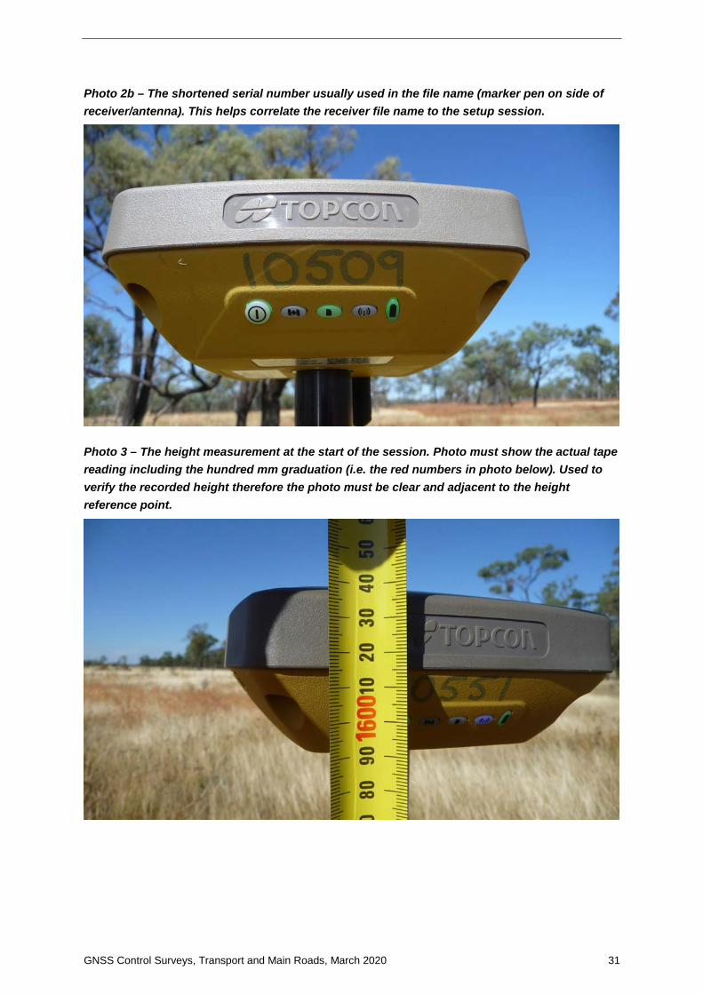
GNSS Control Surveys, Transport and Main Roads, March 2020 31
Photo 2b – The shortened serial number usually used in the file name (marker pen on side of receiver/antenna). This helps correlate the receiver file name to the setup session.
Photo 3 – The height measurement at the start of the session. Photo must show the actual tape reading including the hundred mm graduation (i.e. the red numbers in photo below). Used to verify the recorded height therefore the photo must be clear and adjacent to the height reference point.
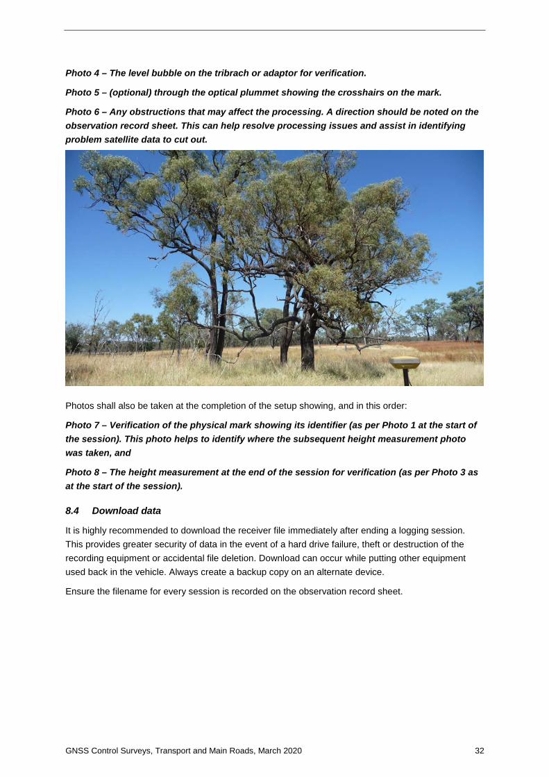
GNSS Control Surveys, Transport and Main Roads, March 2020 32
Photo 4 – The level bubble on the tribrach or adaptor for verification.
Photo 5 – (optional) through the optical plummet showing the crosshairs on the mark.
Photo 6 – Any obstructions that may affect the processing. A direction should be noted on the observation record sheet. This can help resolve processing issues and assist in identifying problem satellite data to cut out.
Photos shall also be taken at the completion of the setup showing, and in this order:
Photo 7 – Verification of the physical mark showing its identifier (as per Photo 1 at the start of the session). This photo helps to identify where the subsequent height measurement photo was taken, and
Photo 8 – The height measurement at the end of the session for verification (as per Photo 3 as at the start of the session).
8.4 Download data
It is highly recommended to download the receiver file immediately after ending a logging session. This provides greater security of data in the event of a hard drive failure, theft or destruction of the recording equipment or accidental file deletion. Download can occur while putting other equipment used back in the vehicle. Always create a backup copy on an alternate device.
Ensure the filename for every session is recorded on the observation record sheet.

GNSS Control Surveys, Transport and Main Roads, March 2020 33
9 Processing and adjustment
Processing and adjustment is covered in detail in the departmental manual Trimble Business Center v5.0 – Processing and Adjusting GNSS Control Networks, October 2019.
It is a highly recommended practice to download data for the observation campaign period of any surrounding CORS even if existing ANJ marks are used as datum. CORS data is generally only available for one month before it is deleted. It is better to have the data available and not use it, than need it and not have it. This approach also has benefits if the network gets added to at a later stage and CORS must be utilised.
9.1 Epoch interval
If the epoch interval of field recorded data is different to the values specified in Section 6.4.1, the baseline processing interval must be set as per Section 6.4.1.
9.2 Daily check processing
At the end of each day all session files should be imported into the GNSS manufacturer’s proprietary software and the baselines processed. An analysis of loop closure misclose should be conducted. This allows early detection of issues and re-observation if necessary.
9.3 Baseline processing
At the completion of the field campaign, process all sessions to baselines using the Rapid or Precise Ephemeris. Prior to processing baselines, a coordinate seed point must be set, and the sessions scrutinised to determine sufficient overlap of the individual sessions (see Section 6.4.2). Flagged baselines shall be inspected and resolved as necessary.
9.4 Network adjustment
Least squares network adjustments shall be conducted at the 95% confidence level. Adjustments will pass the chi-square distribution testing and variance factor (or sigma-zero) will be unity or very close to it, thus proving to be statistically reliable.
9.4.1 Minimally constrained adjustment
Using least squares network adjustment software, a minimally constrained least squares adjustment shall be performed where the network is constrained to a GDA94 latitude and longitude and ellipsoidal height. Results are to be assessed whether they meet Survey Uncertainty requirements. SU shall be estimated as per Section A3.4 of the Addendum of the department’s Trimble Business Center v5.0 – Processing and Adjusting GNSS Survey Control Networks manual, October 2019.
9.4.2 Constrained adjustment
A least squares constrained network adjustment shall be performed where the network is constrained to MGA94 coordinates on known marks. If CORS or a mixture of CORS and ANJ have been utilised, use GDA94 latitude and longitude as constraints.
Depending on project objectives, heights should be constrained to AHD or ellipsoidal heights (avoid mixing in the same adjustment). Verify that the survey passes all relevant tests and meets the required standards including Horizontal Positional Uncertainty.

GNSS Control Surveys, Transport and Main Roads, March 2020 34
9.5 Uncertainty calculation
Uncertainty shall be calculated as per SP1 Standards for the Australian Survey Control Network v2.1. Horizontal Survey Uncertainty (SU) shall be determined based on the minimally constrained least squares adjustment. Horizontal Positional Uncertainty (PU) shall be determined based on a constrained least squares network adjustment. Uncertainties shall meet or be better than the values listed in Section 4.3. The intention of these Uncertainty calculations is for the resultant values to closely resemble uncertainty values that would be generated by the ANJ adjustment once this network has been included. PU shall be estimated as per Section A3.4 of the Addendum of the department’s Trimble Business Center v5.0 – Processing and Adjusting GNSS Survey Control Networks manual, October 2019.
9.5.1 12d Model macro
A macro has been developed for 12d Model users which requires resultant coordinates and associated information to be exported from the network adjustment software in specific formats.
After the minimally constrained adjustment a comma delimited .dat file is to be exported from the GNSS adjustment software as per Table 9.51(a) below.
Table 9.5.1(a) – Export format for SU calculation
Field Example 1 – Constrained mark
Example 2 – Adjusted mark
Point ID CORS1 PM3
Easting 536795.655 527021.321
Northing 6909322.144 6937601.018
Elevation 20.143 6.618
Error ellipse - Semi major axis (m) 0.009
Error ellipse - Semi minor axis (m) 0.009 Example using above table:
CORS1, 536795.655, 6909322.144, 20.143,,
PM3, 527021.321, 527021.321, 6.618,0.009,0.009
After the constrained adjustment, a comma delimited .dat file is to be exported from the GNSS adjustment software as per Table 9.5.1(b).

GNSS Control Surveys, Transport and Main Roads, March 2020 35
Table 9.5.1(b) – Export format for PU calculation
Field Example 1 – Horiz Constrained mark
Example 2 – AHD constrained mark
Point ID CORS1 PM3
Easting 536795.655 527021.321
Northing 6909322.144 6937601.018
Elevation 20.143 6.618
Feature Code PFSC PFSC
Description CORS1 PM3 Brass Plaque
Error ellipse - Semi major axis (m) 0.007
Error ellipse - Semi minor axis (m) 0.007
Easting constraint – horizontal PU (m) @ 1 sigma 0.003
Northing constraint – horizontal PU (m) @ 1 sigma 0.003
Horizontal Quality Fixed in Adjustment Adjusted
Elevation Quality Adjusted Fixed in Adjustment Example using above table:
e.g. CORS1, 536795.655, 6909322.144, 20.143,,,0.007,0.007,Fixed in Adjustment,Adjusted
PM3, 527021.321, 6937601.018, 6.618,0.007,0.007,,,Adjusted,Fixed in Adjustment
The 12d Model macro will generate a report which is useful as a record of the uncertainty calculations and shall form part of the project records.
The macro forms part of the Survey module of the TMR 12d Model Customisation v12.1.0.
9.5.2 Spreadsheet
There is also a excel spreadsheet available to calculate uncertainty values. It requires values to be copied from the output files (as above) into the spreadsheet fields. SU and PU for single or multiple marks can be calculated. The spreadsheet is available on the department’s Spatial Sciences Forum. For externals, contact [email protected]
10 Reports and deliverables
The following files, reports and forms listed below shall form part of the corporate record of survey and included where applicable in the field book:
• raw GNSS receiver files
• RINEX files (v2.11) for all valid observations - correct for mark name, antenna height and type, epoch interval
• GNSS occupation log sheets
• occupation photos of each receiver setup
• least squares network adjustment project
• baseline loop closure details from processing software

GNSS Control Surveys, Transport and Main Roads, March 2020 36
• report on the minimally constrained adjustment (generated from software)
• report on the constrained adjustment (generated from software)
• table of adjusted co-ordinates
• Uncertainty calculation records
• PM Form 6’s used as datum control (essential for traceability)
• CORS Regulation 13 Certificates (essential for traceability)
• new and updated PSM Form 6’s, and
• PSM Maintenance forms for all PM’s searched for.
The TMR Project Manager shall forward to DNRME:
• least squares network adjustment project (if software used is accepted by DNRME)
• raw GNSS receiver files
• RINEX files (v2.11) for all valid observations correct for mark name, antenna height and type
• all new and updated PSM forms
• PSM maintenance forms for all PM’s searched for
• GNSS session observation records, and
• Occupation photos of each receiver setup.

GNSS Control Surveys, Transport and Main Roads, March 2020 37
Appendix A – GNSS Network Workflow

GNSS Control Surveys, Transport and Main Roads, March 2020 38
Appendix B – GFM methodology flowchart
Start – Typical GFM
Density of existing Horz Uncertainty
≤20mm ANJ
Density less than 20km?
Density less than 50km?
Baselines between 10km
to 20km?
Density less than 100km?
Dual 18+ hour sessions
OrCombination of 18+
hour framework with Dual 6+ hour
in-fill
Dual 9+ hour sessions on every mark
Dual 6+ hour sessions on every
markOr
Combination of Dual 6+ hour
framework with 3+ hour in-fill
Dual 6+ hour sessions on every mark
Baselines between 20km
to 50km?
Quality SU < 15mm, PU ≤30mm as per
TMR Surveying Standards
Mark spacing approx 1km
No No No
Yes
No
Yes
Baselines between 50km
to 100km?No
Yes
Dual 18+ hour sessions
OrCombination of 18+
hour framework with Dual 6+ hour
in-fill
No
Yes Yes Yes
Methodology Flowchart – Project Reference Frame for typical GFM Survey

GNSS Control Surveys, Transport and Main Roads, March 2020 39
Appendix C – Observation record example
See next page
Other recommended examples can be found in DNRME’s “Completion of Permanent Survey Mark Plans” (SIG/2013/427 Version 1.05) https://www.business.qld.gov.au/industry/titles-property-construction/surveying/permanent-survey-marks (website correct 22/08/2019)

GNSS Control Surveys, Transport and Main Roads, March 2020 40
Project No:
TMR GNSS SURVEY LOG SHEET
Date: ___________________ Sheet No.________ of _______
Road: ______________________
Surveyor:____________________Antenna:________________________________
Measure to:_____________________________
Mark ID: Approx Chainage:
Receiver ID:
Date & Time Start:
Date & Time End:
Antenna Height Start:
Antenna Height End:
Centred & Levelled at start: At end:
Antenna to Nth:
Lights covered:
Photos (tick): 1. Mark ID 2. Serial No.
Take in this order 3. Ht Measure Start 4. Bubble
5. Optical plummet (optional) 6. Obstructions
7. Mark ID at end 8. Ht Measure End
PM sketch required: PS Sketch Done:
PM centre punched: PM stamped:
Receiver File name:
Rinex File name:
Rinex height to ARP: Checked:
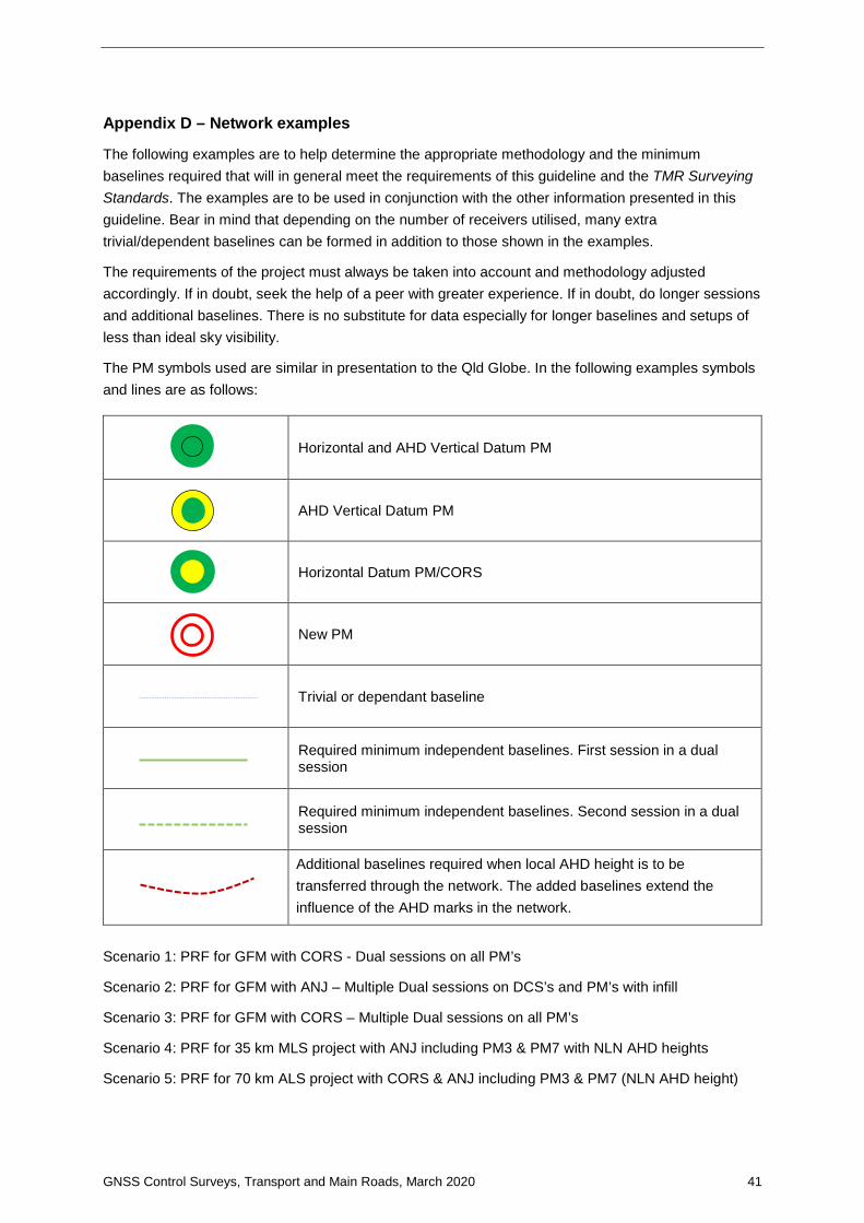
GNSS Control Surveys, Transport and Main Roads, March 2020 41
Appendix D – Network examples
The following examples are to help determine the appropriate methodology and the minimum baselines required that will in general meet the requirements of this guideline and the TMR Surveying Standards. The examples are to be used in conjunction with the other information presented in this guideline. Bear in mind that depending on the number of receivers utilised, many extra trivial/dependent baselines can be formed in addition to those shown in the examples.
The requirements of the project must always be taken into account and methodology adjusted accordingly. If in doubt, seek the help of a peer with greater experience. If in doubt, do longer sessions and additional baselines. There is no substitute for data especially for longer baselines and setups of less than ideal sky visibility.
The PM symbols used are similar in presentation to the Qld Globe. In the following examples symbols and lines are as follows:
Horizontal and AHD Vertical Datum PM
AHD Vertical Datum PM
Horizontal Datum PM/CORS
New PM
Trivial or dependant baseline
Required minimum independent baselines. First session in a dual session
Required minimum independent baselines. Second session in a dual session
Additional baselines required when local AHD height is to be transferred through the network. The added baselines extend the influence of the AHD marks in the network.
Scenario 1: PRF for GFM with CORS - Dual sessions on all PM’s
Scenario 2: PRF for GFM with ANJ – Multiple Dual sessions on DCS’s and PM’s with infill
Scenario 3: PRF for GFM with CORS – Multiple Dual sessions on all PM’s
Scenario 4: PRF for 35 km MLS project with ANJ including PM3 & PM7 with NLN AHD heights
Scenario 5: PRF for 70 km ALS project with CORS & ANJ including PM3 & PM7 (NLN AHD height)

GNSS Control Surveys Guideline, Transport and Main Roads, March 2020 42
Scenario 1: PRF for GFM with CORS – Dual session simultaneous occupations on all PM’s
Session Receivers Independent baselines
CORS CORS CORS A B C
One CORS1 CORS2 CORS3 PM1 PM2 PM3 CORS1 – PM2, PM1 – PM2, PM2 -PM3, PM3-CORS2, PM3-CORS3,
Two CORS1 CORS2 CORS3 PM1 PM2 PM3 CORS1 – PM1, PM1 – PM3, PM3 -CORS1, PM2-CORS2, PM2-CORS3
Total number of occupations (n) for session 1 = 3 receivers (PM1 to PM3) + 3 CORS = 6. Session 1 Independent baselines = (n -1) = (6-1) = 5 Total number of occupations (n) for session 2 = 3 receivers (PM1 to PM3) + 3 CORS = 6. Session 1 Independent baselines = (n -1) = (6-1) = 5 Total number of independent baselines with dual sessions = 10 Dependent baselines
In this example, a user can consider any 5 of the 15 baselines independent, although in practice the shortest lines in a simultaneous receiver session are almost always deemed the minimum baselines and the longest lines are eliminated as dependent or trivial. However, forming loops from different sessions is also an important consideration. When using independent baselines, closed loops cannot consist of one observation session only. Dual sessions of simultaneous observations on all marks can allow closed loop configurations by reconfiguring the independent baselines on the second session. As previously mentioned, a user can consider any 5 of the 15 lines as being independent. In the example below, the second session has 5 lines that are different from the first session to form loops. There is no restriction on which independent baselines can be selected. It is often a case of ‘trial and error’ on achieving the best results in the least squares adjustment.
Quality: H_SU < 15mm, H_PU ≤ 30mm PRFM spacing: approx. 1km CORS density: approx. 40km Baselines: < 50km Dual 6+ hour sessions on every mark
PM2
CORS1
PM1
PM3
CORS3 CORS2
Total number of baselines = n(n – 1)/2 = 6(6 – 1)2 =15

GNSS Control Surveys Guideline, Transport and Main Roads, March 2020 43
Scenario 2: PRF for GFM with ANJ – Multiple Dual sessions on DCS’s and PM’s and infill
Session Receivers Independent baselines No. of independent baselines A B C D
One DCS_1 DCS_2 PM1 PM3 DCS_2 – PM1, PM1 – PM3, PM3 – DCS_1 3
Two DCS_1 DCS_2 PM1 PM3 DCS_2 – PM3, DCS_2 – DCS_1, PM1 – DCS1 3
Three DCS_1 DCS_3 PM5 PM7 DCS_1 – PM5, PM5 – PM7, PM7 – DCS_3 3
Four DCS_1 DCS_2 PM5 PM7 DCS_1 – PM7, DCS_1 – DCS_3, PM5 – DCS3 3
Five PM1 PM2 PM3 PM1 – PM2, PM2 – PM3 2
Six PM1 PM2 PM3 PM1 – PM2, PM2 – PM3 2
Seven PM3 PM4 PM5 PM3 – PM4, PM4 – PM5 2
Eight PM3 PM4 PM5 PM3 – PM4. PM3 – PM5 2
Nine PM5 PM6 PM7 PM5 – PM6, PM6 – PM7 2
Ten PM5 PM6 PM7 PM5 – PM6, PM6 – PM7 2
In this scenario, there are 4 receivers occupying alternate marks from PM1 to PM3 and will have direct connections to occupied Datum Control Survey (DCS) ANJ permanent marks DCS_1 & DCS_2 in dual sessions. This is followed by 4 receivers occupying alternate marks from PM5 to PM7 and will have direct connections to occupied DCS marks DCS_1 and DCS_3 in dual sessions. This is followed by infill with 3 receivers to occupy PM1, PM2 and PM3 for direct connections in dual sessions. This procedure is repeated for PM3, PM4 and PM 5 and finally for PM 5, PM6 and PM7. Every baseline is in a closed loop made up from different sessions.
Quality: H_SU < 15 mm, H_PU ≤ 30 mm PRFM spacing: approx. 1 km ANJ density: approx. 20 km. Baselines: < 20 km Dual 6+ hour sessions on every mark
Or Combination of Dual 6+ hour framework with 2 hour in-fill
PM7
PM1
PM2
PM3
PM5
DCS_1
PM4
PM6
DCS_3 DCS_2
Recommendation (minimum): Dual 6+ hour sessions DCS_1, 2 & 3 Dual 6+ hour sessions PM’s 1, 3, 5 & 7 Dual 2+ hour sessions PM’s 2, 4, & 6
Methodology criteria met Minimum of 3 control survey marks (DCS) Connections between adjacent PRFM’s First & last PRFM direct connection to two DCS Every alternate PRFM direct connection to two DCS

GNSS Control Surveys Guideline, Transport and Main Roads, March 2020 44
Scenario 3: PRF for GFM with CORS – Multiple dual session simultaneous occupations on all PM’s
Session Receivers Independent baselines
CORS CORS CORS CORS A B C D E
1 CORS1 CORS2 CORS3 CORS4 PM1 PM2 PM3 PM4 PM5 CORS1 - PM1, PM1 - PM2, PM2 - PM3, PM3 – PM4, PM4 – PM5, PM5 - CORS4, PM5 – CORS3, PM2 – CORS2
2 CORS1 CORS2 CORS3 CORS4 PM1 PM2 PM3 PM4 PM5 CORS1 – PM2, CORS2 – PM1, PM1 – PM3, CORS1 – PM3, PM2 – PM4, CORS2 – PM4, CORS4 – PM4, CORS3 – PM4
3 CORS1 CORS2 CORS3 CORS4 PM5 PM6 PM7 PM8 CORS1 – PM5, CORS2 – PM5, PM5 – PM6, PM6 -PM7, PM7 – PM8, PM8 – CORS3, PM5 - CORS4
4 CORS1 CORS2 CORS3 CORS4 PM5 PM6 PM7 PM8 CORS3 – PM5, PM5 – PM7, CORS3 – PM6, PM6 – PM8, PM6 – CORS4, CORS 4 – PM8
In this scenario, in addition to the CORS, 5 receivers are used for a dual session from PM1 to PM5 for simultaneous observations. And 4 receivers are then used for dual sessions from PM5 to PM8 for simultaneous observations. Independent baselines are made up from these 2 dual sessions. In this configuration, every observed baseline is in a closed loop made up from different dual sessions. There are many possible configurations. Getting the best result is often ‘trial and error’ by processing each session at a time in a minimally constrained adjustment.
PM5 PM7 PM4
CORS1 CORS4
PM3 PM1
PM8
PM6 PM2
CORS3 CORS2
Quality: H_SU < 15 mm, H_PU ≤ 30 mm PRFM spacing: approx. 5 km CORS density: approx. 80 km Baselines: < 90 km Dual 9+ hour sessions on every mark
Total number of occupations (n) for session 1 = 5 receivers (PM1 to PM5) + 4 CORS = 9. Dual session 1 Independent baselines = (n -1) = (9 -1) = 8
Total number of occupations (n) for session 2 = 5 receivers (PM1 to PM5) + 4 CORS = 9. Dual session 1 Independent baselines = (n -1) = (9 -1) = 8
Total number of occupations (n) for session 3 = 4 receivers (PM1 to PM3) + 4 CORS = 8. Dual session 1 Independent baselines = (n -1) = (8 -1) = 7
Total number of occupations (n) for session 4 = 4 receivers (PM1 to PM3) + 4 CORS = 8. Dual session 1 Independent baselines = (n -1) = (8 -1) = 7
Total number of independent baselines with dual sessions = 30
Recommendation (minimum): Dual 9+ hour sessions on all marks

GNSS Control Surveys Guideline, Transport and Main Roads, March 2020 45
Scenario 4: PRF for 35km MLS project with ANJ including PM3 & PM7 with NLN AHD heights
Methodology criteria met Minimum of 3 datum control survey marks (DCS) Connections between adjacent PRFM’s First & last PRFM directly connected to two DCS Every alternate PRFM directly connected to two DCS
Quality: H_SU < 15 mm, H_PU ≤ 30 mm PRFM spacing: approx. 5 km ANJ density: approx. 50 to 100 km Baselines: < 100 km
Therefore, options are: Single 6+ hour sessions on every mark, Or Combination of longer framework with 6+ hour in-fill Recommendation (minimum): 6+ hour sessions on all marks to create the baselines shown as a minimum If local AHD heights are required from the network, the additional red baselines should be observed as a minimum.
PM7
PM1
PM2
PM3
PM5
DCS_1
PM4
PM6
DCS_3 DCS_2
Same scenario & methodology as Scenario 2, except with larger PRFM spacing, ANJ density and much longer baselines requiring minimum dual 6+ hour sessions on all marks.

GNSS Control Surveys Guideline, Transport and Main Roads, March 2020 46
Scenario 5: PRF for 70 km ALS project with CORS & ANJ including PM3 & PM7 (NLN AHD height)
Session Receivers Independent baselines
CORS CORS CORS CORS A B C D E
1 CORS1 CORS2 CORS3 CORS4 PM1 PM2 PM3 PM4 PM5 CORS1 - PM1, PM1 - PM2, PM2 - PM3, PM3 – PM4, PM4 – PM5, PM5 - CORS4, PM5 – CORS3, PM2 – CORS2
2 CORS1 CORS2 CORS3 CORS4 PM1 PM2 PM3 PM4 PM5 CORS1 – PM2, CORS2 – PM1, PM1 – PM3, CORS1 – PM3, PM2 – PM4, CORS2 – PM4, CORS4 – PM4, CORS3 – PM4
3 CORS1 CORS2 CORS3 CORS4 PM5 PM6 PM7 PM8 CORS1 – PM5, CORS2 – PM5, PM5 – PM6, PM6 -PM7, PM7 – PM8, PM8 – CORS3, PM5 - CORS4
4 CORS1 CORS2 CORS3 CORS4 PM5 PM6 PM7 PM8 CORS3 – PM5, PM5 – PM7, CORS3 – PM6, PM6 – PM8, PM6 – CORS4, CORS 4 – PM8
In this scenario, in addition to the CORS, 5 receivers are used for a dual session from PM1 to PM5 for simultaneous observations. And 4 of receivers are then used for dual sessions from PM5 to PM8 for simultaneous observations. Independent baselines are made up from these 2 dual sessions. In this configuration, every observed baseline is in a closed loop made up from different dual sessions. There are many possible configurations. Getting the best result is often ‘trial and error’ by processing each session at a time in a minimally constrained adjustment.
PM5 PM7 PM4
CORS1 CORS4
PM3 PM1
PM8
PM6 PM2
CORS3 CORS2
Quality: H_SU < 15 mm, H_PU ≤ 30 mm PRFM spacing: approx. 10 km CORS density: approx. 50 to 100 km Baselines: > 100 km Dual 24+ hour sessions on every mark
Total number of occupations (n) for session 1 = 5 receivers (PM1 to PM5) + 4 CORS = 9. Dual session 1 Independent baselines = (n -1) = (9 -1) = 8
Total number of occupations (n) for session 2 = 5 receivers (PM1 to PM5) + 4 CORS = 9. Dual session 1 Independent baselines = (n -1) = (9 -1) = 8
Total number of occupations (n) for session 3 = 4 receivers (PM1 to PM3) + 4 CORS = 8. Dual session 1 Independent baselines = (n -1) = (8 -1) = 7
Total number of occupations (n) for session 4 = 4 receivers (PM1 to PM3) + 4 CORS = 8. Dual session 1 Independent baselines = (n -1) = (8 -1) = 7
Total number of independent baselines with dual sessions = 30
Recommendation (minimum): Dual 24+ hour sessions on all marks