
GM-20/25 and GM-40/45 Series Dual-block Multi-function Gas ...
20
Installation Sheets Manual 121 Gas Combustion Combination Controls and Systems Section G Technical Bulletin GM-20/25 GM-40/45 Issue Date 1298 © 1998 Johnson Controls, Inc. 1 Part No. 24-8711-48, Rev. A www.johnsoncontrols.com Code No. LIT-121892 Introduction Page 3 x Application 3 x Electrical Ratings 3 x Specifications 4 Installation 5 x Mounting 5 x Standard Wiring (From Burner Sequence Control) 6 x 4-Pin Connector Plug Wiring (From Burner Sequence Control) 8 x GM-4_6_ Connection of Impulse Lines 9 x Checkout Procedure 10 Adjustments 11 x GM-_ _1_ (Dual On/Off Fast Open with Flow Adjustment) 11 x GM-_ _2_ (Dual On/Off Step-slow Opening with Flow Adjustment) 12 x GM-_ _3_ (Dual On/Off with Pressure Regulator) 12 x GM-_ _4_ (Dual On/Off with Step-slow Opening with Pressure Regulator) 13 x GM-4_5_ (Dual On/Off with Servo Precision Regulator) 13 x GM-4_6_ (Dual On/Off with Gas/Air Ratio Control) 15 Repairs and Replacement 19 GM-20/25 and GM-40/45 Series Dual-block Multi-function Gas Control Valves
Transcript of GM-20/25 and GM-40/45 Series Dual-block Multi-function Gas ...

Installation Sheets Manual 121Gas Combustion Combination Controls and Systems Section G
Technical Bulletin GM-20/25GM-40/45
Issue Date 1298
© 1998 Johnson Controls, Inc. 1Part No. 24-8711-48, Rev. A www.johnsoncontrols.comCode No. LIT-121892
Introduction Page 3
x Application 3
x Electrical Ratings 3
x Specifications 4
Installation 5
x Mounting 5
x Standard Wiring (From Burner Sequence Control) 6
x 4-Pin Connector Plug Wiring (From Burner Sequence Control) 8
x GM-4_6_ Connection of Impulse Lines 9
x Checkout Procedure 10
Adjustments 11
x GM-_ _1_ (Dual On/Off Fast Open with Flow Adjustment) 11
x GM-_ _2_ (Dual On/Off Step-slow Opening with Flow Adjustment) 12
x GM-_ _3_ (Dual On/Off with Pressure Regulator) 12
x GM-_ _4_ (Dual On/Off with Step-slow Opening with Pressure Regulator) 13
x GM-4_5_ (Dual On/Off with Servo Precision Regulator) 13
x GM-4_6_ (Dual On/Off with Gas/Air Ratio Control) 15
Repairs and Replacement 19
GM-20/25 and GM-40/45 SeriesDual-block Multi-function Gas Control Valves

2 G—GM-20/25 and GM-40/45 Series Dual-block Multi-function Gas Control Valves Technical Bulletin

G—GM-20/25 and GM-40/45 Series Dual-block Multi-function Gas Control Valves Technical Bulletin 3
Introduction
Figure 1: GM Series Dual-block Multi-functionGas Control Valves
The GM Series dual-block multi-function gas control valves are intendedfor use on atmospheric and forced-draft gas burners in heatinginstallations. This multi-functional control on a dual-block valve bodyprovides a compact answer to gas train applications. The GM valvereplaces multiple gas train components, such as on/off gas valves, gaspressure regulators, and modulating gas valves. Optional sizing of bodyflanges offers greater adaptation to diversified burner designs andapplications. Valves are approved to European and North American gasvalve standards.
Typical applications include boilers, burners and ovens, rooftop units,makeup air heaters, hot water heaters, kilns, and paint booths.
Table 1: Electrical RatingsValve Model Operating Voltages Power Consumption
GM-2_ _ _ 230 VAC +10/-15%, 50/60 Hz120 VAC +10/-15%, 50/60 Hz24 VAC +10/-15%, 50/60 Hz
46 VA
GM-4_ _ _ 230 VAC +10/-15%, 50/60 Hz120 VAC +10/-15%, 50/60 Hz24 VAC +10/-15%, 50/60 Hz
46 VA
Application
ElectricalRatings

4 G—GM-20/25 and GM-40/45 Series Dual-block Multi-function Gas Control Valves Technical Bulletin
Table 2: SpecificationsMedia 1st (Manufactured Gas), 2nd (Natural Gas), and 3rd (Liquefied
Petroleum [LP] Gas) Family GasesMaximum InletPressure
Europe:GM-_01 _ and GM-_02_: 360 mbarGM-251_ and GM-252_: 200 mbarAll Other Models 100 mbarNorth America:GM-_01 _ and GM-_02_: 5 psiGM-251_ and GM-252_: 2 psiAll Other Models 0.5 psi
MaximumRegulatingSetting
20 mbar (8 in. W.C.) (GM-_ _3_ and GM-_ _4_)50 mbar (20 in. W.C.) (GM-4_5_ and GM-4_6_)
ReversePressure Rating
150 mbar (60 in. W.C.) minimum; Class A (EN 161)
RegulatorClassification
Spring Regulator (GM-_ _3_ and GM-_ _4_): Class B (EN 88)Servo Regulator (GM-4_5_): Class A (EN 88)
PermissibleAmbientTemperature
-15 to 60°C (5 to 140°F)
BodyConnections
Detachable flanges with pipe thread 3/8 to 1-1/2 in. NPT or Rp
Valve TorsionGroup
Group 2 (EN 88 and EN 161)
Pressure Taps Flanges: 9.0 mm (0.35 in.) spigot for flexible tubingBody: Rp 1/8 thread standard (multi-position)
Rp 1/4 thread special (multi-position) GM-4 onlyMaterials Body and Flanges: Die-cast aluminum
Diaphragms and Seals: Perbunan rubberSolenoid Enclosure: IEC 529 (NEMA 1 and IP 54)
Filter Segment Standard Dirt Strainer: 0.5 mm (0.02 in.) metal meshOptional Filter Set: 0.05 mm (0.002 in.) nylon mesh and fleece filter
Operating TimeRating
100% Continuous
Valve Timings Closing Time: < 1 secondOpening Time: < 1 to 15 secondsDead Time: < 1 second
ElectricalConnections
Standard Wiring: PG 13.5 compression fitting with cage-typeterminal blocks inside the electrical box
Optional Wiring: 1/2 in. NPT conduit adapter compression fitting or4-pin connector plug (ISO 4400 [DIN 43650])
Coil InsulationClass
Class F
Agency Listings IAS (AGA/CGA) Certificate Numbers: C0197002C0197004
European Certificate Number: CE 0063AN3731SpecificationStandards
EN 88, EN 126, and EN 161Standards Complying with the EMC DirectiveStandards Complying with the Low Voltage DirectiveANSI Standards, Z21.18, Z21.21, and Z21.78Canadian Standards CAN1-6.3 and CAN1-6.5
The performance specifications are nominal and conform to acceptable industry standards. Forapplication at conditions beyond these specifications, consult the local Johnson Controls office.Johnson Controls, Inc. shall not be liable for damage resulting from misapplication or misuse of itsproducts.
Refer to the GM-20/25 and GM-40/45 Series Product Bulletin (LIT-4350340) for necessary information onoperating and performance specifications of this product.
Specifications
G—GM-20/25 and GM-40/45 Series Dual-block Multi-function Gas Control Valves Technical Bulletin 5
Installation
IMPORTANT: This technical bulletin is intended as a guide forauthorized service personnel installing or servicingJohnson Controls products. Carefully follow allinstructions in this sheet and all instructions on theappliance. Limit repairs, adjustments, and servicing tothe operations listed in this sheet or on the appliance.
! WARNING: The system must meet all applicable codes. Improperinstallation may cause fire, explosions, propertydamage, and injuries or death.
Carefully follow all instructions in this sheet and all instructions on theappliance. Limit repairs, adjustments, and servicing to the operations listedin this sheet or on the appliance.
! WARNING: Fire or explosion hazard. Shut off the gas supply atthe main manual shutoff valve before installing orservicing the GM Series valve.
1. Ensure that the maximum ambient temperature is not exceeded(see Table 2).
2. Check the power supply voltage for compatibility with the requiredvalve voltage. All wiring must conform to national and local electricalcodes and regulations.
3. When installing the valve on the manifold, the gas must flow throughthe valve body in the direction indicated by the arrow on the body. Ifthe valve is installed with the gas flow opposite the arrow, leakage canoccur.
4. Shut off the gas at the main manual shutoff valve.
5. Mount the valve. It is recommended that the flanges be mounted tothe pipe separately with the valve then mounted between thetwo flanges. The filter plate assembly should be installed (using thelonger bolts) between the inlet flange and the valve.
Mounting

6 G—GM-20/25 and GM-40/45 Series Dual-block Multi-function Gas Control Valves Technical Bulletin
The GM Series valve may be mounted on a horizontal manifold withthe solenoid actuator pointed up (vertical) or in any position notexceeding 90o from the vertical. The valve may also be mounted on avertical manifold in any position around its axis (see Figure 2). Do notinstall the solenoid actuator upside down. Install vertically whereverpossible.
90° Maxim umfrom Vertica l
90° Maxim umfrom Vertica l
L im ited Horizon tal and Vertica l
Figure 2: GM Series Valve Mounting Position
Use an approved pipe joint sealing compound on male threads beforeassembly.
6. Remove excess compound after mounting the flanges to the pipe.Threads of pipe and nipples must be smooth and free of tears andburrs. Steam clean all piping to remove foreign substances such ascutting oil or thread chips.
! WARNING: Shock hazard. Avoid electrical shock and equipmentdamage by disconnecting electrical power to the valvebefore proceeding.
! CAUTION: Equipment damage hazard. To prevent possiblegrounding of the 24 VAC transformer secondary, donot connect the ground wire on 24 VAC models.
Follow the procedure below to wire the valve when using the standardPG 13.5 cable compression electrical connection.
1. Observe that the operating voltage is identical to the information onthe product identification label.
2. Route the electrical cable for the valve solenoid from the burnersequence control to the valve.
3. Remove the cover of one of the electrical box and make wiringconnections in accordance with Figure 3.
4. Reattach the electrical box cover.
Standard Wiring(From BurnerSequenceControl)

G—GM-20/25 and GM-40/45 Series Dual-block Multi-function Gas Control Valves Technical Bulletin 7
Note: Figure 3 shows wiring connections for individual valve opening.For simultaneous valve opening, wire a jumper betweenTerminals V1 and V2 of either the electrical box on the first orsecond valve.
5. Use a wrench to tighten the PG 13.5 cable compression plug to securewires and prevent moisture from entering the terminal box.
Note: If an optional 1/2 in. NPT thread electrical connector or 4-pinDIN 43650 (ISO 4400) electrical connector (each orderedseparately) is used for wiring, refer to the documentation suppliedwith the electrical connector for specific wiring instructions.
V1 V2
V1
V2
N
N V 2 V 1 N V 1 V 2
V 1
V 2
V 1
V 2
Addtional Connection(May be used to connect pilotor bypass valves. Break awayplastic to open.)
GND GND
GND*
Electrical BoxConnection
*
PG 13 .5 CableCompression P lug(Facto ry Installed )
W iring C onnec tionsN = CommonV1 = Line Va lve 1V2 = Line Va lve 2GND = Earth Ground*(* Do not connect earth ground fo r 24 VAC mode ls.)
Figure 3: Standard Wiring Electrical Connections

8 G—GM-20/25 and GM-40/45 Series Dual-block Multi-function Gas Control Valves Technical Bulletin
! WARNING: Shock hazard. Avoid electrical shock and equipmentdamage by disconnecting electrical power to the valvebefore proceeding.
! CAUTION: Equipment damage hazard. To prevent possiblegrounding of the 24 VAC transformer secondary, donot connect the ground wire on 24 VAC models.
Use the following procedure to wire the valve when using a factory-installed 4-pin DIN 43650 (ISO 4400) electrical plug connection.
1. Observe that the operating voltage is identical to the information onthe product identification label.
2. Route the electrical cable for the valve solenoid from the burnersequence control to the valve.
3. Make wiring connections in accordance with Figure 4.
Note: Figure 4 shows wiring connections for individual valve opening.For simultaneous valve opening, wire a jumper between terminalsV1 and V2 of either the electrical box on the first or second valve.
PE (Ground)
2
3
1 N (Comm on)
13
2
Line (Valve 1)
Line (Valve 2)
Term inal DesignationsV1 V2
Figure 4: 4-Pin Wiring Electrical Connections
4-Pin ConnectorPlug Wiring(From BurnerSequenceControl)

G—GM-20/25 and GM-40/45 Series Dual-block Multi-function Gas Control Valves Technical Bulletin 9
The internal diameter of the impulse tubes for the combustion air (PA) andthe combustion chamber pressure (PF) should be 4.0 mm (5/32 in.), seeFigure 5. Make the connections as short as possible and route to preventthe entry of condensate into the controller. The installation of acondensation trap in the connection line from the combustion chamber ishighly recommended. Do not close the connection for PF if not used.
IMPORTANT: Avoid sharp bends or kinks in the tubing to avoiddamage to the tubing and allow for an accurate pressurereading.
PF PA
Figure 5: Impulse Line Connections
GM-4_6_Connection ofImpulse Lines

10 G—GM-20/25 and GM-40/45 Series Dual-block Multi-function Gas Control Valves Technical Bulletin
! WARNING: Fire or explosion hazard. Verify that the valvefunctions properly and there are no gas leaks. Followthis checkout procedure before leaving the installation.Failure to verify proper valve installation, equipmentoperation, and gas tight connections may result in fire,explosion, property damage, and injuries or death.
1. Shut off the gas at the main manual shutoff valve and open thepressure connection between the manual shutoff valve and the GMvalve.
2. Connect air tubing with a maximum pressure of 1-1/2 times thevalve’s maximum operating pressure (as indicated on the valve) to theopened pressure connection.
3. Paint the pipe connections and flanges of the valve with a rich soapand water solution to check for leakage.
If bubbles occur, this is an indication of a leak. To stop a leak, tightenjoints and pipe connections. Replace the part if the leak cannot bestopped.
If bubbles do not occur, remove the air tubing and close the upstreampressure connection.
4. Open the main manual shutoff valve.
5. Refer to the Adjustments section to make any necessary valve settingadjustments.
! WARNING: Fire or explosion hazard. Valve settings must be inaccordance with the appliance or equipmentmanufacturer’s specifications.
6. Before leaving the installation, observe at least three completeoperating cycles to ensure that all components are functioningcorrectly.
CheckoutProcedure

G—GM-20/25 and GM-40/45 Series Dual-block Multi-function Gas Control Valves Technical Bulletin 11
Adjustments
IMPORTANT: All adjustments must be made in conjunction with thegas appliance and in accordance with the appliancemanufacturer’s instructions. Only authorizedpersonnel should make adjustments. See each valvemodel version for specific adjustments.
! WARNING: Explosion hazard. The minimum flow rate of thevalve must not be adjusted below the minimum safeworking rate of the appliance.
It is recommended that the flange pressure tap connections be used tomonitor the inlet and outlet valve pressure while performing each of thespecific adjustment procedures. These pressure connections are located onthe inlet and outlet flanges of the valve in the form of a brass spigot,sealed with a captive brass needle screw. To monitor the inlet or outletpressure using these taps, turn the appropriate needle screw in acounterclockwise direction one or two turns and fit a 9 mm diameterflexible tube over the spigot. After all valve adjustments have been made,remove the flexible tube and turn the needle screw in a clockwise directionuntil tight, sealing the spigot.
This valve provides manual flow adjustment throughout the full range ofzero to maximum flow. For flow rate adjustment, loosen the unsealedmounting screw on the plastic adjustment knob at the top of the solenoidcoil. Hand turn the adjustment knob clockwise to decreaseor counterclockwise to increase the flow rate through the valve (seeFigure 6). Tighten the mounting screw to secure the adjustment knob atthe desired flow rate.
Figure 6: Manual Flow Adjustment Knob
GM-_ _1_(Dual On/OffFast Openwith FlowAdjustment)

12 G—GM-20/25 and GM-40/45 Series Dual-block Multi-function Gas Control Valves Technical Bulletin
This valve provides adjustable step/slow opening for smooth ignition in aburner application. The valve is factory set to maximum start gas positionand maximum flow position. Adjust the hydraulic damper at the top of thesolenoid coil to set the desired flow rate through the valve as well as thedesired start gas flow rate.
To adjust the maximum flow rate, loosen the unsealed mounting screw onthe aluminum hydraulic damper housing. Hand turn the housing clockwiseuntil the desired setting is obtained. Tighten the mounting screw to securethe adjustment knob at the desired flow rate.
To adjust the start gas position, remove the plastic cap from the hydraulicdamper housing and turn the brass screw clockwise until the desiredsetting is obtained (see Figure 7). Replace the plastic cap.
A
V M A X.
Figure 7: Hydraulic Damper Housing
This valve provides spring regulation to maintain the gas pressure at thevalve outlet. For outlet pressure adjustment, loosen the unsealed mountingscrew on the plastic regulator knob at the top of the solenoid coil. Handturn the regulator knob clockwise to increase or counterclockwise todecrease the outlet pressure of the valve (see Figure 8). Tighten themounting screw to secure the adjustment knob at the desired outletpressure.
SO
LL W
E R T S T./R E G . S E T PO
I NT
Figure 8: Spring Pressure Regulator Adjustment Knob
GM-_ _2_(Dual On/OffStep-slowOpeningwith FlowAdjustment)
GM-_ _3_(Dual On/Offwith PressureRegulator)

G—GM-20/25 and GM-40/45 Series Dual-block Multi-function Gas Control Valves Technical Bulletin 13
This valve provides controls for step/slow opening (for smooth ignition)and pressure regulation (for maintaining outlet gas pressure).
Refer to the GM-_ _3_ version for setting the gas pressure at the valveoutlet. For setting of the start gas position and maximum flow rate, see theGM-_ _2_ version.
This valve provides servo regulation for precision control of the valveoutlet pressure. To set the valve for the desired outlet pressure, the startgas pressure must be adjusted first.
To set the start gas position, energize the solenoid coil to open the valveseats. Remove the pressure tap plug (see Figure 9) located below the gasoutlet pipe connection and measure the start gas pressure. The adjustmentscale (PST) indicates the factory-set start gas pressure (see Figure 10);therefore, a subsequent fine adjustment may be necessary. Use thehexagonal tool provided (or an acceptable Allen wrench) to adjust the PST
scale and obtain the desired start gas pressure.
PressureTap P lug
Figure 9: Valve Outlet Pipe Connection
P ST
P G
5-50
2
6
10
Figure 10: P ST and PG Adjustment Scales (Metric Shown)
GM-_ _4_(Dual On/OffStep-slowOpening withPressureRegulator)
GM-4_5_(Dual On/Offwith ServoPrecisionRegulator)

14 G—GM-20/25 and GM-40/45 Series Dual-block Multi-function Gas Control Valves Technical Bulletin
The start gas pressure (PST) remains at the set level until the pressure tapplug is replaced and tightened. The pressure then rises to the setpoint (PG).
IMPORTANT: PG must be greater then PST in order for the valve tooperate properly.
Once the desired start gas pressure has been obtained, the outlet pressure(PG) can be adjusted. To set the outlet pressure position, energize thesolenoid coil to open the valve seats. Remove an outlet pressure tap plugfrom the valve body and measure the servo pressure regulator performanceand timing characteristics (see Figure 11). The adjustment scale (PG)indicates the factory-set outlet pressure (see Figure 10), which can beadjusted using the hexagonal tool provided (or an acceptable Allenwrench) to obtain the desired servo pressure regulator performance andtiming characteristics.
P G
P ST
3 to 12 Seconds
Time (s)
P G
Figure 11: Servo Pressure Regulator Performance vs.Timing Characteristics
Cycle the valve three times to check for proper performance, leaving aminimum time of 20 seconds between cycles to evacuate the pressurechamber.
G—GM-20/25 and GM-40/45 Series Dual-block Multi-function Gas Control Valves Technical Bulletin 15
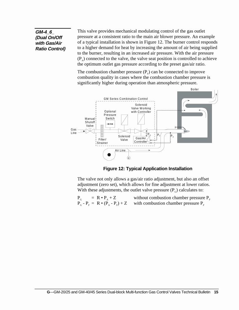
This valve provides mechanical modulating control of the gas outletpressure at a consistent ratio to the main air blower pressure. An exampleof a typical installation is shown in Figure 12. The burner control respondsto a higher demand for heat by increasing the amount of air being suppliedto the burner, resulting in an increased air pressure. With the air pressure(PA) connected to the valve, the valve seat position is controlled to achievethe optimum outlet gas pressure according to the preset gas/air ratio.
The combustion chamber pressure (PF) can be connected to improvecombustion quality in cases where the combustion chamber pressure issignificantly higher during operation than atmospheric pressure.
M
P G P AP F
G asL ine
M anualShutoffValve
O ptiona lPressure
Sw itch
Filte r/S trainer
A ir L ine
G M Series Com bination Control
So lenoidValve W orkingw ith Contro lle r
Gas/AirController
Bo iler
So lenoidValve
Figure 12: Typical Application Installation
The valve not only allows a gas/air ratio adjustment, but also an offsetadjustment (zero set), which allows for fine adjustment at lower ratios.With these adjustments, the outlet valve pressure (PG) calculates to:
PG = R • PA + Z without combustion chamber pressure PF
PG - PF = R • (PA - PF) + Z with combustion chamber pressure PF
GM-4_6_(Dual On/Offwith Gas/AirRatio Control)

16 G—GM-20/25 and GM-40/45 Series Dual-block Multi-function Gas Control Valves Technical Bulletin
To adjust the valve, first check the factory settings. The adjustments forthe gas/air ratio (R scale) and zero set (Z scale) are located on both sides ofthe gas/air ratio control module (see Figure 13). The factory settings are:
x Gas/air ratio (R): 1:2
x Zero set (Z): 0
Z
0- +
R1
0,6
234
56
Figure 13: Zero Set and Gas/Air Ratio Adjustments
Before starting the burner, make sure that the gas/air ratio and zero setsettings are correct for the specific appliance. If necessary, use thehexagonal tool provided (or an acceptable Allen wrench) to adjust thesesettings to the appliance manufacturer’s recommendations. If the specificratio settings are not available, ensure that the appliance is safe to operateat the factory settings.
Start the burner and gradually increase the output of the valve. If theburner does not light, check for a flame during the ignition phase. If theflame extinguishes immediately, the system may have excess air. Checkagain and adjust the gas/air ratio (R) setting if necessary.
With the burner in the maximum output position, adjust the gas/air ratio(R scale) to meet the desired flue gas analysis readings. The ratio (R) ofgas outlet pressure (PG) to combustion air pressure (PA) is adjustable withina range of 0.6:1 to 6:1 (see Figure 14).
Check the flue gas analyses on low and high output settings withoutmanipulating the adjustments. Once the readings have been checked, finetune (by adjusting the zero set) the settings if necessary. In cases wherecombustion chamber pressure (PF) is used, connect it and repeat the gas/airratio (R) adjustment.
Gas/Air Ratio (R)Adjustment

G—GM-20/25 and GM-40/45 Series Dual-block Multi-function Gas Control Valves Technical Bulletin 17
Z 0.6:1
0.7:1
1:1
2:1
3:15:16:1
00 4 8 12 16 20
4
8
12
16
20
P A (in. W.C.)P A - P F (in. W.C.)
P G (in. W.C.)
P G - P F (in. W.C.)
Figure 14: Analyses Chart
With the correct gas/air ratio (R) set, there may be some minor deviations(caused by friction, etc.) at very low pressures. To allow for fineadjustment of the valve, the zero set can be changed. The zero set adds aconstant offset to the flue gas analyses, affecting the low output figuresmore significantly than the high output figures.
Zero set (Z) can be accomplished by a parallel shift of the characteristiccurve from -2 to +2 mbar (-0.8 to +0.8 in. W.C.) (see Figure 14).
Set the burner to the low fire position, perform a flue gas analysis, andvary the outlet pressure by adjusting the Z scale until the desired flue gasanalysis readings are obtained.
If adjusting the zero set (Z) results in an unacceptable high output figure,repeat the adjustments starting with the gas/air ratio (R) adjustmentprocedure.
Zero Set (Z)Adjustment

18 G—GM-20/25 and GM-40/45 Series Dual-block Multi-function Gas Control Valves Technical Bulletin
G—GM-20/25 and GM-40/45 Series Dual-block Multi-function Gas Control Valves Technical Bulletin 19
Repairs and Replacement
Field repairs must not be made, except to replace the filter or strainer. Fora replacement part, contact the nearest Johnson Controls representative orthe original equipment manufacturer.
! CAUTION: Label all wires prior to disconnection when servicingvalves. Wiring errors can cause improper anddangerous operation. Verify proper operation afterservicing.
Perform the following steps to replace the filter or strainer.
1. Clean or replace the filter or strainer with each recommendedinspection or at a minimum each annual functional inspection.
2. Close the main manual shutoff valve and disconnect field wiring. Aseach wire is disconnected, label it with the correct terminaldesignation.
3. Remove the screws on the flanges and remove the valve and filterplate.
4. Clean or replace the filter or strainer. Reinstall the filter plate andvalve.
5. Refasten the flange screws to the valve and reconnect field wiring.
! WARNING: Fire or explosion hazard. Verify that the valvefunctions properly and there are no gas leaks. Followthis checkout procedure before leaving the installation.Failure to verify proper valve installation, equipmentoperation, and gas tight connections may result in fire,explosion, property damage, and injuries or death.
6. Open the pressure connection between the manual shutoff valve andthe GM valve.
7. Connect air tubing with a maximum pressure of 1-1/2 times thevalve’s maximum operating pressure (as indicated on the valve) to theopened pressure connection.

20 G—GM-20/25 and GM-40/45 Series Dual-block Multi-function Gas Control Valves Technical Bulletin
8. Paint the pipe connections and flanges of the valve with a rich soapand water solution.
If bubbles occur, this is an indication of a leak. To stop a leak, tightenjoints and pipe connections. Replace the part if the leak cannot bestopped.
If bubbles do not occur, remove the air tubing and close the upstreampressure connection.
9. Open the main manual shutoff valve.
10. Observe at least three complete operating cycles to ensure that allcomponents are functioning correctly.
Controls Group www.johnsoncontrols.com507 E. Michigan Street FAN 121P.O. Box 423 Installation Sheets ManualMilwaukee, WI 53201 Printed in U.S.A.


