
Global Operational Data Link (GOLD) Manual - …code7700.com/pdfs/icao_doc_10037_gold.pdfGlobal...
291
Doc 10037 AN/509 Global Operational Data Link (GOLD) Manual Disclaimer This document is an unedited version of an ICAO publication and has not yet been approved in final form. As its content may still be supplemented, removed, or otherwise modified during the editing process, ICAO shall not be responsible whatsoever for any costs or liabilities incurred as a result of its use. Advance edition (unedited) INTERNATIONAL CIVIL AVIATION ORGANIZATION
-
Upload
trankhuong -
Category
Documents
-
view
232 -
download
0
Transcript of Global Operational Data Link (GOLD) Manual - …code7700.com/pdfs/icao_doc_10037_gold.pdfGlobal...

Doc 10037 AN/509
Global Operational Data Link (GOLD)
Manual
Disclaimer
This document is an unedited version of an ICAO publication and has not yet been approved in final form. As its content may still be supplemented, removed, or otherwise modified during the editing process, ICAO shall not be responsible whatsoever for any costs or liabilities incurred as a result of its use.
Advance edition (unedited)
INTERNATIONAL CIVIL AVIATION ORGANIZATION

Published in separate English, French, Russian, Arabic, Chinese and Spanish editions by the INTERNATIONAL CIVIL AVIATION ORGANIZATION 999 Robert-Bourassa Boulevard, Montréal, Quebec, Canada H3C 5H7 For ordering information and for a complete listing of sales agents and booksellers, please go to the ICAO website at www.icao.int First Edition, 2016 Doc 10037, Global Operational Data Link (GOLD) Manual Order Number: xxxxx ISBN xxx-xx-xxxx-xxx-x © ICAO 2016 All rights reserved. No part of this publication may be reproduced, stored in a retrieval system or transmitted in any form or by any means, without prior permission in writing from the International Civil Aviation Organization.

AMENDMENTS
Amendments are announced in the supplements to the Products and Services Catalogue; the Catalogue and its supplements are available on the ICAO website at www.icao.int. The space below is provided to keep a record of such amendments.
RECORD OF AMENDMENTS AND CORRIGENDA
AMENDMENTS CORRIGENDA
No. Date Entered by No. Date Entered by

(iv)
FOREWORD
HISTORICAL BACKGROUND
The Global Operational Data Link (GOLD) Manual (Doc 10037) is the result of the progressive evolution of the
Asia-Pacific (APAC) Initial Future Air Navigation System (FANS 1/A) Operations Manual, the North Atlantic (NAT)
Guidance Material for ATS Data Link Services in North Atlantic Airspace and the European (EUR) LINK2000+ Guidance
Material for the aeronautical telecommunication network baseline 1 (ATN B1). These documents provided guidance on
ATS data link services, namely data link initiation capability (DLIC), automatic dependent surveillance – contract (ADS-C)
and controller-pilot data link communications (CPDLC).
Each of these founding documents provided guidance on a regional basis. However, in recognition of the need to
provide globally harmonized guidance on data link operations, the Global Operational Data Link Document (GOLD), First
Edition, which merged the APAC and NAT guidance material, was adopted by the APAC and NAT Regions in 2010.
The Second Edition of the GOLD, which incorporated the LINK2000+ guidance material, was published 26 April 2013
and adopted that same year by all ICAO Regions providing ADS-C and CPDLC services. The GOLD represented a very
significant step towards the global harmonization of ADS-C and CPDLC implementation.
At the first working group meeting of the Operational Data Link Panel (OPLINKP-WG/1, March 2013, Montréal), the
OPLINKP-WG reviewed the Implementation and Amendment Programme of the GOLD. The group recognized the value
of the GOLD to serve as a basis for global harmonization of DLIC, ADS-C and CPDLC operations and agreed to elevate
it to an ICAO manual. At the sixth meeting of the OPLINKP Working Group of the Whole (OPLINKP--WG/WHL/6,
October 2013, Montréal), the group further agreed that the first edition of the Global Operational Data Link (GOLD)
Manual would be based on the second edition of the GOLD that was developed by the Regions.
The Global Operational Data Link (GOLD) Manual addresses ATS data link service provision, operator readiness,
controller and flight crew procedures.
This manual supersedes Parts II (DLIC), III (ADS-C) and IV (CPDLC) of the Manual of Air Traffic Services Data Link
Applications (Doc 9694, First Edition).
SCOPE AND PURPOSE
The GOLD Manual provides guidance and information concerning data link operations and is intended to facilitate the
uniform application of Standards and Recommended Practices contained in Annex 2 — Rules of the Air, Annex 10 —
Aeronautical Telecommunications and Annex 11 — Air Traffic Services, the provisions in the Procedures for Air
Navigation Services — Air Traffic Management (PANS-ATM, Doc 4444) and, when applicable, the Regional
Supplementary Procedures (Doc 7030).
This guidance material is intended to improve safety and maximize operational benefits by promoting seamless and
interoperable data link operations throughout the world. This edition applies to DLIC, ADS-C, and CPDLC using
FANS 1/A and ATN B1 technologies. Additional guidance is provided that applies to CPDLC for automatic dependent
surveillance – broadcast (ADS-B) in-trail procedure (ITP).
The GOLD Manual is structured as follows:
a) Chapter 1 provides an overview of data link (i.e. CPDLC and ADS-C) operations, including operational
capabilities, systems, and services;
b) Chapter 2 provides administrative provisions related to data link, including service provision, operator
considerations for usage, and flight planning;

(v) Global Operational Data Link (GOLD) Manual
c) Chapter 3 provides controller and radio operator procedures for CPDLC and ADS-C;
d) Chapter 4 provides flight crew procedures for CPDLC and ADS-C;
e) Chapter 5 provides information on advanced air traffic services supported by data link, including re-
route procedures, tailored arrivals, and the in-trail procedure; and
f) Chapter 6 provides State aircraft data link operations.
The following personnel and organizations should be familiar with relevant aspects of its contents: regulators, airspace
planners, aircraft operators, flight operations officers/flight dispatchers, air navigation service providers (ANSPs),
aeronautical stations, communication service providers (CSPs), satellite service providers (SSPs) and radio operators,
training organizations, regional/State monitoring agencies, automation specialists at air traffic service and radio facilities,
and aircraft manufacturers and equipment suppliers.
The guidance will support the following activities:
a) the States’ roles and responsibilities in relation to the following:
1) safety oversight of air navigation services;
2) operational approval, flight crew training and qualification; and
3) design approval of aircraft data link systems.
b) the development of agreements and/or contractual arrangements between ANSPs and aircraft
operators and their respective communication service providers;
c) the development of operational procedures; and
d) operational monitoring, analysis, and exchange of operational data among regions, States, and
communication service providers.
FUTURE DEVELOPMENTS
In order to keep this manual relevant and accurate, suggestions for improving it in terms of format, content or
presentation are welcome. Any such recommendation or suggestion will be examined and, if found suitable, will be
included in regular updates to the manual. Regular revision will ensure that the manual remains both pertinent and
accurate. Comments on this manual should be addressed to:
The Secretary General
International Civil Aviation Organization
999 Robert-Bourassa Boulevard
Montréal, Quebec H3C 5H7
Canada
––––––––––––––––––––––

TABLE OF CONTENTS
Page
Publications …………………………………………………………………………………………………………………..(xiv)
Abbreviations and Acronyms ……………………………………………………………………………………………..(xvi)
Glossary ……………………………………………………………………………………………………………………….(xix)
Chapter 1. Overview of data link operations ................................................................................................... ..1-1
1.1 Data link operational capabilities ........................................................................................................ ..1-1
1.1.1 Data link benefits ................................................................................................................ ..1-1
1.1.2 Data link systems – interoperability standards .................................................................... ..1-1
1.1.3 Data link services – safety and performance specifications ................................................ ..1-6
1.1.4 Airspace types and their data link operational capabilities .................................................. ..1-7
1.2 Data link systems and services ........................................................................................................... ..1-9
1.2.1 Network descriptions and message acknowledgements .................................................... ..1-9
1.2.2 Data link initiation capability (DLIC) .................................................................................... 1-12
1.2.3 CPDLC connection management ....................................................................................... 1-17
1.2.4 Controller-pilot data link communications (CPDLC) ............................................................ 1-33
1.2.5 Automatic dependent surveillance – contract (ADS-C) ....................................................... 1-40
Chapter 2. Administrative provisions related to data link operations .......................................................... ..2-1
2.1 ANSP service provision ...................................................................................................................... ..2-1
2.1.1 Initial Operational Implementation of CPDLC and ADS-C .................................................. ..2-1
2.1.2 ATC automated data link functions ..................................................................................... ..2-3
2.1.3 Contractual considerations for CSP .................................................................................... ..2-9
2.1.4 Aeronautical information, notifications, and interfacility agreements ................................... 2-10
2.1.5 Monitoring and data recording ............................................................................................ 2-11
2.2 Operator considerations for CPDLC and ADS-C usage...................................................................... 2-12
2.2.1 Initial use of CPDLC and ADS-C ........................................................................................ 2-12
2.2.2 Local/regional monitoring agencies .................................................................................... 2-13
2.3 Flight planning .................................................................................................................................... 2-13
2.3.1 General ............................................................................................................................... 2-13
2.3.2 CPDLC and ADS-C ............................................................................................................ 2-13
Chapter 3. Controller and radio operator procedures .................................................................................... ..3-1
3.1 Overview .................................................................................................................................... ..3-1
3.1.1 General ............................................................................................................................... ..3-1
3.1.2 When to use voice and when to use CPDLC ...................................................................... ..3-1
3.2 CPDLC connection management and voice communication transfers ............................................... ..3-2
3.2.1 General ............................................................................................................................... ..3-2
3.2.2 Establish CPDLC connection .............................................................................................. ..3-3
3.2.3 Transfer voice communications with CPDLC connection transfer ...................................... ..3-3
3.2.4 Termination of the CPDLC connection ............................................................................... ..3-5
3.2.5 CPDLC connection with aircraft transiting small data link area ........................................... ..3-5

(vii) Table of Contents
3.3 CPDLC – Uplink messages ................................................................................................................ ..3-7
3.3.1 General ............................................................................................................................... ..3-7
3.3.2 Use of free text ................................................................................................................... ..3-8
3.3.3 “EXPECT” uplink messages ............................................................................................... ..3-9
3.3.4 Vertical clearances ............................................................................................................. 3-10
3.3.5 Report/confirmation requests .............................................................................................. 3-12
3.3.6 Creating multi-element uplink messages ............................................................................ 3-13
3.3.7 Weather deviations ............................................................................................................. 3-14
3.4 CPDLC – Downlink messages ............................................................................................................ 3-14
3.4.1 General ............................................................................................................................... 3-14
3.4.2 Clarifying a downlink message ........................................................................................... 3-14
3.4.3 Responses/acknowledgements .......................................................................................... 3-15
3.4.4 Responding to multi-element requests ............................................................................... 3-16
3.4.5 Offering alternative clearances to requests......................................................................... 3-17
3.5 ADS-C .................................................................................................................................... 3-18
3.5.1 General ............................................................................................................................... 3-18
3.5.2 ADS contracts ..................................................................................................................... 3-19
3.5.3 ADS-C connection management ........................................................................................ 3-19
3.5.4 ADS contract - periodic ....................................................................................................... 3-22
3.5.5 ADS contract - waypoint change event ............................................................................... 3-23
3.5.6 ADS contract - vertical range change and lateral deviation events ..................................... 3-23
3.6 Separation .................................................................................................................................... 3-23
3.6.1 General – ADS-C ................................................................................................................ 3-23
3.6.2 Vertical separation – ADS-C ............................................................................................... 3-24
3.6.3 Lateral separation – ADS-C ................................................................................................ 3-24
3.6.4 Longitudinal separation – ADS-C ........................................................................................ 3-24
3.7 Route conformance ............................................................................................................................ 3-25
3.8 Alerting service ................................................................................................................................... 3-25
3.9 Emergency procedures ....................................................................................................................... 3-26
3.9.1 General ............................................................................................................................... 3-26
3.9.2 CPDLC and ADS-C emergency .......................................................................................... 3-26
3.9.3 ADS-C emergency report without a CPDLC emergency message ..................................... 3-27
3.10 Non-routine procedures ...................................................................................................................... 3-27
3.10.1 General ............................................................................................................................... 3-27
3.10.2 Voice communications related to data link .......................................................................... 3-28
3.10.3 Data link initiation failure ..................................................................................................... 3-29
3.10.4 Data link service failures ..................................................................................................... 3-30
3.10.5 Using CPDLC to relay messages ....................................................................................... 3-33
Chapter 4. Flight crew procedures ................................................................................................................... ..4-1
4.1 Overview .................................................................................................................................... ..4-1
4.1.1 General ............................................................................................................................... ..4-1
4.1.2 Operational differences between voice communications and CPDLC ................................ ..4-1
4.1.3 When to use voice and when to use CPDLC ...................................................................... ..4-2
4.2 Logon .................................................................................................................................... ..4-3
4.2.1 General ............................................................................................................................... ..4-3
4.2.2 When to log on initially for data link services ...................................................................... ..4-6
4.2.3 Automatic transfer of CPDLC and ADS-C services between ATS units ............................. ..4-7
4.2.4 Transfer voice communications with the CPDLC connection transfer ................................ ..4-7
4.2.5 Exiting CPDLC and ADS-C service areas........................................................................... ..4-8

Table of Contents (viii)
4.3 CPDLC – Uplink messages ................................................................................................................ ..4-8
4.3.1 General ............................................................................................................................... ..4-8
4.3.2 Flight crew response times for CPDLC uplink messages ................................................... ..4-9
4.3.3 Conditional clearances ....................................................................................................... 4-10
4.3.4 “EXPECT” uplink messages ............................................................................................... 4-11
4.3.5 Uplink messages containing FMS-loadable data ................................................................ 4-12
4.4 CPDLC – Downlink messages ............................................................................................................ 4-12
4.4.1 General ............................................................................................................................... 4-12
4.4.2 Free text.............................................................................................................................. 4-14
4.4.3 Unsupported messages and voice responses to CPDL requests ....................................... 4-14
4.4.4 CPDLC reports and confirmation requests ......................................................................... 4-14
4.4.5 Weather deviations and offsets…………………………………………………………………..4-15
4.4.6 CPDLC position reporting…………………………………………………………………………4-18
4.5 Automatic dependant surveillance – contract (ADS-C) ....................................................................... 4-19
4.5.1 General ............................................................................................................................... 4-19
4.6 Emergency procedures ....................................................................................................................... 4-20
4.6.1 General ............................................................................................................................... 4-20
4.6.2 CPDLC and ADS-C emergency .......................................................................................... 4-21
4.7 Non-routine procedures ...................................................................................................................... 4-21
4.7.1 General ............................................................................................................................... 4-21
4.7.2 Voice communications related to data link .......................................................................... 4-21
4.7.3 Data link initiation failure ..................................................................................................... 4-22
4.7.4 Data link system failures ..................................................................................................... 4-23
4.7.5 Using CPDLC to relay messages ....................................................................................... 4-24
Chapter 5. Advanced air traffic services supported by data link .................................................................. ..5-1
5.1 Re-route procedures ........................................................................................................................... ..5-1
5.1.1 General ............................................................................................................................... ..5-1
5.1.2 Re-route procedures – AOC initiated (DARP) ..................................................................... ..5-1
5.1.3 Re-route procedures – ATC initiated .................................................................................. ..5-4
5.2 Tailored arrival (TA) ............................................................................................................................ 5-11
5.2.1 General ............................................................................................................................... 5-11
5.2.2 Provisions for the TA service .............................................................................................. 5-11
5.2.3 Clearance delivery and execution ....................................................................................... 5-12
5.3 Automatic dependent surveillance – broadcast in-trail procedure (ADS-B ITP) .................................. 5-16
5.3.1 General ............................................................................................................................... 5-16
5.3.2 Provisions for the ADS-B ITP service and operator eligibility.............................................. 5-17
5.3.3 Clearance delivery and execution ....................................................................................... 5-17
Chapter 6. State aircraft data link operations ................................................................................................. ..6-1
6.1 General .................................................................................................................................... ..6-1
6.2 Military assumes responsibility for separation of aircraft (MARSA) ..................................................... ..6-2
6.3 Air-to-air refuelling (AAR) .................................................................................................................... ..6-2
6.4 Formation flight data link procedures .................................................................................................. ..6-7
6.5 ADS-C reports .................................................................................................................................... ..6-8

(ix) Table of Contents
List of Tables
Table 1-1 Designators for aircraft and ATSU (ground) data link systems ........................................................ ..1-4
Table 1-2 Designators for subnetworks ........................................................................................................... ..1-6
Table 1-3 Types of data link systems and operations ..................................................................................... ..1-9
Table 1-4 Examples of responses to CPDLC uplink messages ...................................................................... 1-34
Table 1-5 Precedence of responses ................................................................................................................ 1-35
Table 1-6 Examples of multi-element CPDLC uplink messages ..................................................................... 1-36
Table 1-7 Example of CPDLC dialogue ........................................................................................................... 1-40
Table 1-8 Figure of merit values ...................................................................................................................... 1-57
Table 2-1 Supporting technology for transfers between FANS 1/A and ATN B1 ............................................. ..2-4
Table 2-2 Descriptors for CPDLC/ADS-C equipment and capabilities in Item 10 ............................................ 2-14
Table 3-1 CONTACT/MONITOR message elements ...................................................................................... ..3-4
Table 3-2 “EXPECT” uplink message elements for flight crew requests ......................................................... ..3-9
Table 3-3 Procedural “EXPECT” uplink message elements ............................................................................ 3-10
Table 3-4 Conditional vertical clearances applicable during flight manoeuvre ................................................ 3-11
Table 3-5 Voice phraseology related to CPDLC .............................................................................................. 3-28
Table 4-1 Messages and indications regarding use of message latency monitor............................................ ..4-6
Table 4-2 Conditional clearance clarification of vertical clearances ................................................................ 4-11
Table 4-3 Voice phraseology related to CPDLC .............................................................................................. 4-22
Table 5-1 AOC initiated re-route procedures ................................................................................................... ..5-2
Table 5-2 ATC initiated re-route procedures ................................................................................................... ..5-6
Table 5-3 Tailored arrival clearance delivery and execution ........................................................................... 5-13
Table 5-4 ADS-B ITP clearance delivery and execution .................................................................................. 5-18
Table 6-1 MARSA initiation and termination procedures ................................................................................. ..6-2
Table 6-2 Air refuelling data link procedures ................................................................................................... ..6-3
Table 6-3 Single aircraft or formation joining an ALTRV data link procedures ................................................ ..6-8
Table 6-4 Formation break-up or departure from ALTRV data link procedures ............................................... ..6-8
List of Figures
Figure 1-1 Overview of a data link system ........................................................................................................ ..1-2
Figure 1-2 Different ATS unit/aircraft interoperable connectivity ...................................................................... ..1-3
Figure 1-3 Uplink and message assurance ...................................................................................................... 1-10
Figure 1-4 Downlink and network acknowledgement ....................................................................................... 1-11
Figure 1-5 Uplink and logical acknowledgement .............................................................................................. 1-12
Figure 1-6 Downlink and logical acknowledgement .......................................................................................... 1-12
Figure 1-7 Initial logon exchanges .................................................................................................................... 1-16
Figure 1-8 Air-ground address forwarding message sequence (Transfer between areas where
data link is provided) ....................................................................................................................... 1-17
Figure 1-9 Ground-ground address forwarding using logon forwarding message ............................................ 1-17
Figure 1-10 Rejection of CPDLC uplinks from the NDA ..................................................................................... 1-18
Figure 1-11 CPDLC connection sequence ......................................................................................................... 1-19
Figure 1-12 Successful attempt to establish a CPDLC connection (inactive) ..................................................... 1-20
Figure 1-13 Termination of active CPDLC connection ........................................................................................ 1-22
Figure 1-14 Next data authority notification ........................................................................................................ 1-23
Figure 1-15 Connection forwarding .................................................................................................................... 1-24
Figure 1-16 Life cycle of the CPDLC connection process .................................................................................. 1-25
Figure 1-17 Nominal sequence for initial CPDLC connection establishment and transfer of
CPDLC connection using air-ground address forwarding................................................................ 1-26
Figure 1-18 Nominal sequence for initial CPDLC connection establishment and transfer of

Table of Contents (x)
CPDLC connection using ground-ground address forwarding (no use of Next Authority Notified) .. 1-27
Figure 1-19 Nominal sequence for initial CPDLC connection establishment and transfer of
CPDLC connection using ground-ground address forwarding (use of Next Authority Notified) ....... 1-28
Figure 1-20 Depiction of the change in route of an aircraft ................................................................................. 1-29
Figure 1-21 Sending a new NDA following a re-route ......................................................................................... 1-30
Figure 1-22 Non-receipt of the NDA message .................................................................................................... 1-31
Figure 1-23 Connection request from an ATS unit not designated as the NDA .................................................. 1-31
Figure 1-24 Successful CPDLC connection following a re-send of the NDA message ....................................... 1-32
Figure 1-25 Termination of both active and inactive CPDLC connection for general use – NDA NONE ............ 1-33
Figure 1-26 Termination of both active and inactive CPDLC connection for general use –
[free text] and flight crew assist ....................................................................................................... 1-33
Figure 1-27 Message/dialogue status for CPDLC request and clearance exchange.......................................... 1-38
Figure 1-28 Message/dialogue status for CPDLC confirmation request and report exchange ........................... 1-39
Figure 1-29 ADS-C periodic contract sequence ................................................................................................. 1-42
Figure 1-30 ADS-C emergency and non-emergency report sequence ............................................................... 1-43
Figure 1-31 ADS-C event contract sequence ..................................................................................................... 1-44
Figure 1-32 ADS-C waypoint change event ....................................................................................................... 1-45
Figure 1-33 ADS-C level range deviation event ................................................................................................. 1-45
Figure 1-34 ADS-C level range deviation event report ....................................................................................... 1-46
Figure 1-35 ADS-C lateral deviation event ......................................................................................................... 1-46
Figure 1-36 ADS-C lateral deviation event report ............................................................................................... 1-47
Figure 1-37 Effect of offset on ADS-C lateral deviation event report .................................................................. 1-47
Figure 1-38 No lateral deviation event report if active route is different to route held by ATS unit ..................... 1-48
Figure 1-39 ADS-C basic group.......................................................................................................................... 1-50
Figure 1-40 ADS-C flight identification group ..................................................................................................... 1-50
Figure 1-41 ADS-C Earth reference group ......................................................................................................... 1-50
Figure 1-42 ADS-C air reference group .............................................................................................................. 1-51
Figure 1-43 ADS-C airframe identification group ................................................................................................ 1-51
Figure 1-44 ADS-C meteorological group ........................................................................................................... 1-51
Figure 1-45 ADS-C predicted route group .......................................................................................................... 1-52
Figure 1-46 ADS-C fixed projected intent group ................................................................................................. 1-52
Figure 1-47 ADS-C intermediate projected intent group ..................................................................................... 1-53
Figure 1-48 Multiple ADS periodic contracts with different groups ..................................................................... 1-55
Figure 1-49 Multiple ADS periodic contracts with different reporting intervals .................................................... 1-55
Figure 1-50 Multiple and different ADS event contracts ..................................................................................... 1-56
Figure 1-51 Calculation of ADS-C periodic reporting interval ............................................................................. 1-58
Figure 3-1 CPDLC connection transfer - separate messages .......................................................................... ..3-4
Figure 3-2 Transiting small data link area ......................................................................................................... ..3-6
Figure 3-3 Priorities for ADS-C connections ..................................................................................................... 3-21
Figure 3-4 ADS-C connection not available due to congestion ........................................................................ 3-22
Figure 4-1 Depiction of logon addresses and CPDLC/ADS-C services on en route chart ................................ ..4-5
Figure 4-2 Offset and weather deviation ........................................................................................................... 4-15
Figure 4-3 Weather deviation clearance up to 20 NM (37 km) left of route ...................................................... 4-16
Figure 4-4 Subsequent weather deviation clearance up to 50 NM (93 km) left of route ................................... 4-16
Figure 4-5 Subsequent weather deviation clearance up to 30 NM (55.5 km) right of route .............................. 4-17
Figure 4-6 Waypoint sequencing anomaly ....................................................................................................... 4-20
Figure 5-1 The DARP process.......................................................................................................................... ..5-4
Figure 5-2 ATC initiated re-route – first waypoint in the new route is on the current route and
there is no route discontinuity .......................................................................................................... ..5-7
Figure 5-3 ATC initiated re-route – first waypoint in the new route is on the current route and
there is route discontinuity ............................................................................................................... ..5-8
Figure 5-4 ATC initiated re-route – first waypoint in the new route is not on the current route and

(xi) Table of Contents
there is no route discontinuity .......................................................................................................... ..5-9
Figure 5-5 ATC initiated re-route – first waypoint in the new route is not on the current route and
there is route discontinuity ............................................................................................................... 5-10
Figure 5-6 ATC initiated re-route – aircraft is cleared direct to a fix that is located downstream
in the current route .......................................................................................................................... 5-11
Figure 6-1 Air refuelling pattern ........................................................................................................................ ..6-3
LIST OF APPENDICES
Appendix A. DLIC and CPDLC message elements ......................................................................................... …A-1
A.1 General .................................................................................................................................... …A-1
A.2 Messages for DLIC and CPDLC connection establishment/termination ............................................. …A-3
A.2.1 Air-ground data link messages for DLIC ............................................................................. …A-3
A.2.2 Ground-ground data link messages for DLIC...................................................................... …A-3
A.2.3 Data link messages for CPDLC connection ........................................................................ …A-4
A.3 Response attribute of CPDLC message element ............................................................................... …A-5
A.4 CPDLC message elements ................................................................................................................. …A-7
A.4.1 Route message elements…………………………………………………………… ................. …A-7
A.4.2 Lateral message elements………………………………………………………… ................... ..A-11
A.4.3 Level message elements………………………………………………………………… ........... ..A-15
A.4.4 Crossing constraint message elements………………………………………… ..................... ..A-24
A.4.5 Speed message elements……………………………………………………………… ............. ..A-27
A.4.6 Air traffic advisory message elements………………………………………………… ............ ..A-30
A.4.7 Voice communications message elements…………………………………………… ............ ..A-34
A.4.8 Spacing message elements…………………………………………………………… .............. ..A-37
A.4.9 Emergency/urgency message elements……………………………………………… ............. ..A-40
A.4.10 Standard response message elements………………………………………………… ........... ..A-41
A.4.11 Supplemental message elements……………………………………………………… ............ ..A-43
A.4.12 Free text message elements…………………………………… ............................................. ..A-44
A.4.13 System management message elements………………… .................................................. ..A-45
A.5 Message elements parameters ........................................................................................................... ..A-48
A.6 Message elements recommended not to use ..................................................................................... ..A-54
A.6.1 FANS 1/A uplink message elements……………… ............................................................. ..A-54
A.6.2 FANS 1/A downlink message elements .............................................................................. ..A-56
A.6.3 ATN B1 uplink message element ........................................................................................ ..A-57
A.6.4 ATN B1 downlink message element ................................................................................... ..A-57
Appendix B. Regional/State-specific information ........................................................................................... ..B-1
B.1 General .................................................................................................................................... ..B-1
B.2 European (EUR) Region ..................................................................................................................... ..B-1
B.2.1 Administrative provisions related to data link operations .................................................... ..B-1
B.2.1.1 ANSP service provision ...................................................................................... ..B-1
B.2.1.2 EUR - NSAP address registry ............................................................................. ..B-3
B.2.1.3 Flight plan provisions .......................................................................................... ..B-3
B.2.1.4 Logon criteria ...................................................................................................... ..B-4
B.2.1.5 Lack Timer .......................................................................................................... ..B-4
B.2.2 Controller procedures ......................................................................................................... ..B-4
B.2.2.1 Reverting from CPDLC to voice .......................................................................... ..B-4

Table of Contents (xii)
B.2.2.2 Preconditions for the operational exchange of CPDLC messages ..................... ..B-5
B.2.2.3 Uplink messages ................................................................................................ ..B-5
B.2.2.4 Operational timers used by ATS unit .................................................................. ..B-8
B.2.2.5 Transfer of data communications with open dialogues ....................................... ..B-9
B.2.2.6 Abnormal situations ............................................................................................ ..B-9
B.2.2.7 Downlink error messages ................................................................................... B-10
B.2.3 Flight crew procedures ....................................................................................................... B-12
B.2.3.1 General ............................................................................................................... B-12
B.2.3.2 Latency time monitor (LTM) ................................................................................ B-14
B.2.3.3 Operational use of LACK .................................................................................... B-14
B.2.3.4 Operational timers used by the aircraft ............................................................... B-15
B.2.3.5 Use of degrees in ACL messages ...................................................................... B-16
B.2.3.6 Transfer of data communications with open dialogues ....................................... B-16
B.2.3.7 Multiple open requests for a same type .............................................................. B-17
B.2.3.8 Abnormal situations ............................................................................................ B-17
B.2.3.9 Uplink error messages ........................................................................................ B-17
B.2.4 Advanced data link operations ............................................................................................ B-21
B.2.5 State aircraft data link operation ......................................................................................... B-21
Table B-EUR-1. Data link services by control area (CTA)............................................................................. ..B-2
Table B-EUR-2. Operational error downlink messages ................................................................................ B-11
Table B-EUR-3. Operational error uplink messages ..................................................................................... B-18
B.3 North-America (NAM) Region ............................................................................................................. B-21
B.3.1 Administrative provisions related to data link operations .................................................... B-21
B.3.1.1 ANSP service provision ...................................................................................... B-21
B.3.2 Controller and radio operator procedures ........................................................................... B-23
B.3.2.1 Use of AT PILOTS DISCRETION ....................................................................... B-23
B.3.3 Flight crew procedures ....................................................................................................... B-24
B.3.3.1 Use of AT PILOTS DISCRETION ....................................................................... B-24
B.3.4 Advanced data link operations ............................................................................................ B-24
B.3.5 State aircraft data link operation ......................................................................................... B-24
Table B-NAM-1. Data link services by control area (CTA) ............................................................................ B-21
B.4 North Atlantic (NAT) Region ............................................................................................................... B-24
B.4.1 Administrative provisions related to data link operations .................................................... B-24
B.4.1.1 ANSP service provision ...................................................................................... B-24
B.4.1.2 Uplink message elements unsuited for NAT operations ..................................... B-25
B.4.1.3 Unsupported CPDLC downlink message elements – NAT ................................. B-26
B.4.1.4 Reporting requirements in NAT airspace where ADS-C is available .................. B-26
B.4.2 Controller and radio operator procedures ........................................................................... B-27
B.4.2.1 Voice communication procedures ....................................................................... B-27
B.4.3 Flight crew procedures ....................................................................................................... B-27
B.4.3.1 Voice communication procedures ....................................................................... B-27
B.4.4 Advanced data link operations ............................................................................................ B-29
B.4.5 State aircraft data link operation ......................................................................................... B-29
Table B-NAT-1. Data link services by control area (CTA) ............................................................................. B-24
Table B-NAT-2. Unsupported CPDLC downlink message elements ............................................................ B-26
B.5 Pacific (PAC) Region .......................................................................................................................... B-29

(xiii) Table of Contents
B.5.1 Administrative provisions related to data link operations .................................................... B-29
B.5.1.1 ANSP service provision ...................................................................................... B-29
B.5.1.2 Exchange of turbulence information in Fukuoka FIR .......................................... B-33
B.5.2 Controller and radio operator procedures ........................................................................... B-34
B.5.3 Flight crew procedures ....................................................................................................... B-34
B.5.4 Advanced data link operations ............................................................................................ B-34
B.5.5 State aircraft data link operation ......................................................................................... B-34
Table B-PAC-1. Data link services by control area (CTA) ............................................................................ B-29
Appendix C. Operator/aircraft specific information ....................................................................................... ..C-1
C.1 FANS 1/A and ATN B1 product availability ......................................................................... ..C-1
C.2 Verifying aircraft registration ............................................................................................... ..C-2
C.3 CPDLC connection management ....................................................................................... ..C-3
C.4 Flight crew display – response and acknowledgement ....................................................... ..C-3
C.5 FMS processing of waypoints in position reports ................................................................ ..C-4
C.6 Multiple request messages ................................................................................................. ..C-5
C.7 Waypoint sequencing ......................................................................................................... ..C-5
C.8 Open uplinks at time of transfer of communications ........................................................... ..C-6
C.9 Variable constraints ............................................................................................................ ..C-6
C.10 ADS C emergency report interval default ........................................................................... ..C-7
C.11 Message latency monitor .................................................................................................... ..C-7
C.12 Terminating ADS C connections ......................................................................................... ..C-8
C.13 SATCOM channel format .................................................................................................... ..C-8
C.14 Transfer of ATS unit ............................................................................................................ ..C-8
C.15 Number of ADS C connections ........................................................................................... ..C-9
C.16 Lateral deviation events on offsets ..................................................................................... ..C-9
C.17 Assigned block altitude ....................................................................................................... ..C-9
C.18 FANS 1/A-ATN B1 aircraft behaviour for automatic CPDLC transfers ................................ C-10
C.19 CM contact procedure ........................................................................................................ C-10
C.20 Duplicate CPDLC uplink message processing.................................................................... C-11
C.21 Response to end-service and error uplink messages ......................................................... C-11
C.22 CPDLC connection after logon ........................................................................................... C-12
C.23 ARINC 424 oceanic waypoints ........................................................................................... C-12
C.24 STANDBY response to pilot-initiated downlink request ...................................................... C-13
— — — — — — — —

PUBLICATIONS (referred to in this manual)
International Civil Aviation Organization (ICAO)
Annex 1 — Personnel Licensing
Annex 2 — Rules of the Air
Annex 4 — Aeronautical Charts
Annex 6 — Operation of Aircraft
Part I — International Commercial Air Transport — Aeroplanes
Part II — International General Aviation — Aeroplanes
Part III — International Operations — Helicopters
Annex 10 — Aeronautical Telecommunications
Volume II — Communication Procedures including those with PANS status
Volume III — Communication Systems
Annex 11 — Air Traffic Services
Annex 15 — Aeronautical Information Services
Designators for Aircraft Operating Agencies, Aeronautical Authorities and Services (Doc 8585)
Manual on Airborne Surveillance Applications (Doc 9994)
Performance-based Communication and Surveillance (PBCS) Manual (Doc 9869) (in preparation)
Performance-based Navigation Manual (PBN) (Doc 9613)
Procedures for Air Navigation Services — Air Traffic Management (PANS-ATM, Doc 4444)
Procedures for Air Navigation Services — ICAO Abbreviations and Codes (PANS-ABC, Doc 8400)
Regional Supplementary Procedures (Regional SUPPs, Doc 7030)
In Trail Procedure (ITP) Using Automatic Dependent Surveillance - Broadcast (ADS-B) (Circular 325)
Aeronautical Radio, Inc. (ARINC)
Navigation Systems Data Base (ARINC 424)

(xv) Publications
European Organization for Civil Aviation Equipment (EUROCAE) and Radio Technical Commission for
Aeronautics (RTCA, Inc.)
Interoperability Requirements for ATS Applications Using ARINC 622 Data Communications (FANS 1/A INTEROP Standard, RTCA DO-258A/EUROCAE ED-100A)
Interoperability Requirements Standard for Aeronautical Telecommunication Network Baseline 1 (ATN B1 INTEROP
Standard, RTCA DO-280B/EUROCAE ED-110B)
Future Air Navigation System 1/A — Aeronautical Telecommunication Network Interoperability Standard (FANS 1/A — ATN B1 INTEROP Standard, RTCA DO-305A/EUROCAE ED-154A)
Safety, Performance and Interoperability Requirements Document for In-Trail Procedure in Oceanic Airspace (RTCA DO-312/EUROCAE ED-159) and Supplement
––––––––––––––––––––––

ABBREVIATIONS AND ACRONYMS
When the following abbreviations and acronyms are used in this manual, they have the meanings shown. Where the term has “(ICAO)” annotated, the acronym has already been defined as such in Annexes and/or Procedures for Air Navigation Services (PANS).
AAR Air-to-air refuelling
ACARS Aircraft communications addressing and reporting system
ACAS Aircraft collision avoidance system (ICAO)
ACC Area control centre (ICAO)
ACL ATS clearance (data link service)
ACM ATS communications management (data link service)
ADS Automatic dependent surveillance (retained for reference with non-updated documents. This term
would normally be used to refer to ADS-C)
ADS-B Automatic dependent surveillance – broadcast (ICAO)
ADS-C Automatic dependent surveillance – contract (ICAO)
AFN ATS facilities notification
AGL Above ground level (ICAO)
AIC Aeronautical information circular (ICAO)
AIDC ATS interfacility data communications (ICAO)
AIP Aeronautical Information Publication (ICAO)
AIREP Air-report (ICAO)
ALTRV Altitude reservation
AMC ATS microphone check (data link service)
AMS(R)S Aeronautical mobile satellite (route) service (ICAO)
ANSP Air navigation service provider
AOC Aeronautical operational control (ICAO)
ARCP Air refuelling control point
AREX Air refuelling exit point
ARIP Air refuelling initial point
ATC Air traffic control (ICAO)
ATM Air traffic management (ICAO)
ATN Aeronautical telecommunication network (ICAO)
ATN B1 Aeronautical telecommunication network baseline 1, as defined by RTCA DO-280B/EUROCAE
ED-110B.
Note.— In the context of CPDLC, ATN B1 means that the data link system on an aircraft, the
ATS unit ground system, and communication service provision comply with ETSI EN 303 214 and
the EASA Certification Specifications and Acceptable Means of Compliance for Airborne
Communications, Navigation and Surveillance CS-ACNS. ATN B1 consists of the following data
link applications:
a) context management (CM) for data link initiation capability (DLIC); and
b) limited CPDLC for ATS communications management (ACM), ATS clearance (ACL), and
ATC microphone check (AMC).
ATS Air traffic service (ICAO)

(xvii) Abbreviations and Acronyms
ATSU ATS unit
CADS Centralized ADS-C system
CDA Current data authority (see ICAO definition for current data authority)
CM Context management (data link application)
CNS Communications, navigation and surveillance (ICAO)
CNS/ATM Communications, navigation and surveillance/air traffic management (ICAO)
CPDLC Controller-pilot data link communications (ICAO)
CPL Current flight plan
CRC Cyclic redundancy check
CSP Communication service provider
CTA Control area (ICAO)
DARP Dynamic airborne re-route procedure
D-ATIS Data link – automatic terminal information service (data link service)
DCL Departure clearance (data link service)
DCPC Direct controller-pilot communications
DLIC Data link initiation capability (ICAO)
DM Downlink message
DSC Downstream clearance (data link service)
EMERG Emergency (ICAO)
ETD Estimated time of departure or estimating departure (ICAO)
FANS Future air navigation system
FANS 1/A Future air navigation system - initial, as defined by RTCA DO-258A/EUROCAE ED-100A, or
previous standards that defined the FANS 1/A capability.
Note.— FANS 1/A generally means that the data link system on an aircraft, the ATS unit
ground system, and communication service provision comply with the standard. In certain cases,
specific reference is made to a particular type of FANS 1/A aircraft as follows:
a) FANS 1/A+ means that the aircraft completely complies with Revision A of the standard,
which includes message latency monitor; and
b) FANS 1/A ADS-C means that the aircraft complies with AFN and ADS-C applications, but
does not include the CPDLC application.
FDPS Flight data processing system (ICAO)
FIR Flight information region (ICAO)
FL Flight level
FLIPCY Flight plan consistency (data link service)
FMC Flight management computer
FMS Flight management system
FOM Figure of merit
FPL Filed flight plan
GPS Global positioning system (USA)
HF High frequency (3-30 Mhz) (ICAO)
IATA International Air Transport Association
ICAO International Civil Aviation Organization (ICAO)
ITP In trail procedure
LDE Lateral deviation event
LRDE Level range deviation event
MARSA Military assumes responsibility for separation of aircraft
MAS Message assurance
MASPS Minimum aviation system performance standards

Abbreviations and Acronyms (xviii)
MEL Minimum equipment list (ICAO)
MET Meteorological or meteorology (ICAO)
MIN Message identification number
MMEL Master minimum equipment list (ICAO)
MRN Message reference number
NDA Next data authority (see ICAO definition for next data authority)
ORT Operational requirements table
PANS-ATM Procedures for Air Navigation Services — Air Traffic Management (Doc 4444) (ICAO)
PBC Performance-based communication
PBCS Performance-based communication and surveillance
PBN Performance-based navigation
PBS Performance-based surveillance
POS Position report message
RCP Required communication performance
RNAV Area navigation
RNP Required navigation performance
RSP Required surveillance performance
RTF Radiotelephone
SARPs Standards and Recommended Practices (ICAO)
SATCOM Satellite communication
SATVOICE Satellite voice communication
SELCAL Selective calling system (ICAO)
SSP Satellite service provider
TA Tailored arrival
UM Uplink message
UPR User preferred route
VDL M0/A VHF data link mode 0/A subnetwork
VDL M2 VHF data link mode 2 subnetwork
VHF Very high frequency (30-300 Mhz) (ICAO)
VRE Vertical rate change event
WCE Waypoint change event
––––––––––––––––––––––

GLOSSARY
When the subsequent terms are used in this manual, they have the following meanings. Where the term has “(ICAO)”
annotated, the term has already been defined as such in Annexes and Procedures for Air Navigation Services (PANS).
Active flight plan (see flight plan).
Aeronautical Information Publication (AIP). A publication issued by or with the authority of a State and
containing aeronautical information of a lasting character essential to air navigation. (ICAO)
Aeronautical mobile satellite (route) service (AMS(R)S). An aeronautical mobile-satellite service reserved for
communications relating to safety and regularity of flights, primarily along national or international civil air routes. (ICAO)
Note.— AMS(R)S includes both voice and data. In this document, the use of AMS(R)S for voice
communications is referred to as SATVOICE to reflect the operational use of the term in standard phraseology and
messages.
Aeronautical mobile service (AMS). A mobile service between aeronautical stations and aircraft stations, or
between aircraft stations, in which survival craft stations may participate; emergency position-indicating radio beacon stations may also participate in this service on designated distress and emergency frequencies. (ICAO, RR S1.32)
Aeronautical operational control (AOC). Communication required for the exercise of authority over the initiation,
continuation, diversion or termination of flight for safety, regularity and efficiency reasons. (ICAO)
Aeronautical station. A land station in the aeronautical mobile service. In certain instances, an aeronautical station
may be located, for example, on board ship or on a platform at sea. (ICAO, RR S1.81)
Aeronautical telecommunication network (ATN). A global internetwork architecture that allows ground, air-
ground and avionic data subnetworks to exchange digital data for the safety of air navigation and for the
regular, efficient and economic operation of air traffic services. (ICAO)
Air traffic control (ATC) clearance. Authorization for an aircraft to proceed under conditions specified by an air
traffic control unit.
Note 1.— For convenience, the term “air traffic control clearance” is frequently abbreviated to “clearance”
when used in appropriate contexts.
Note 2.— The abbreviated term “clearance” may be prefixed by the words “taxi”, “take-off”, “departure”,
“en-route”, “approach” or “landing” to indicate the particular portion of flight to which the air traffic control clearance
relates.
(ICAO)

Glossary (xx)
Air traffic control (ATC) service. A service provided for the purpose of:
a) preventing collisions:
1) between aircraft; and
2) on the manoeuvring area between aircraft and obstructions; and
b) expediting and maintaining an orderly flow of air traffic. (ICAO)
Air traffic management (ATM). The dynamic, integrated management of air traffic and airspace including air traffic
services, airspace management and air traffic flow management — safely, economically and efficiently —
through the provision of facilities and seamless services in collaboration with all parties and involving airborne
and ground-based functions. (ICAO)
Air traffic service (ATS). A generic term meaning variously, flight information service, alerting service, air traffic
advisory service, air traffic control service (area control service, approach control service or aerodrome control
service). (ICAO)
Air traffic services unit (ATS unit). A generic term meaning variously, air traffic control unit, flight information
centre or air traffic services reporting office. (ICAO)
Airborne collision avoidance system (ACAS). An aircraft system based on secondary surveillance radar (SSR)
transponder signals which operates independently of ground-based equipment to provide advice to the pilot
on potential conflicting aircraft that are equipped with SSR transponders. (ICAO)
Aircraft. Any machine that can derive support in the atmosphere from the reactions of the air other than the
reactions of the air against the earth’s surface. (ICAO)
Active flight plan. (See flight plan).
Aircraft address. A unique combination of 24 bits available for assignment to an aircraft for the purpose of air-ground communications, navigation and surveillance. (ICAO)
Aircraft identification. A group of letters, figures or a combination thereof which is either identical to, or the coded
equivalent of, the aircraft call sign to be used in air-ground communications, and which is used to identify the
aircraft in ground-ground air traffic services communications. (ICAO)
Note 1.— The aircraft identification does not exceed 7 characters and is either the aircraft registration or the
ICAO designator for the aircraft operating agency followed by the flight identification.
Note 2.— ICAO designators for aircraft operating agencies are contained in ICAO Doc 8585, Designators for
Aircraft Operating Agencies, Aeronautical Authorities and Services.
Aircraft registration. A group of letters, figures or a combination thereof which is assigned by the State of Registry
to identify the aircraft. It is also referred to as registration mark.
Air-report. A report from an aircraft in flight prepared in conformity with requirements for position, and operational
and/or meteorological reporting. (ICAO)

(xxi) Glossary
Altitude reservation (ALTRV). Airspace utilization under prescribed conditions normally employed for the mass
movement of aircraft or other special requirements which cannot otherwise be accomplished.
Appropriate authority.
a) Regarding flight over the high seas: The relevant authority of the State of Registry.
b) Regarding flight other than over the high seas: The relevant authority of the State having sovereignty over
the territory being overflown. (ICAO)
Area control centre (ACC). A unit established to provide air traffic control service to controlled flights in control
areas under its jurisdiction. (ICAO)
Area navigation (RNAV) specification. See navigation specification. (ICAO)
ATC waypoint. A waypoint contained in Item 15 of the ICAO flight plan, or as amended by ATC.
Note.— A waypoint inserted by the flight crew for purposes of conducting flight operations such as points of no
return are not ATC waypoints.
ATM operation. An individual operational component of air traffic services. Examples of ATM operations include
the application of separation between aircraft, the re-routing of aircraft, and the provision of flight information.
ATS interfacility data communication (AIDC). Automated data exchange between air traffic services units,
particularly in regard to co-ordination and transfer of flights. (ICAO)
ATS surveillance service. A term used to indicate a service provided directly by means of an ATS surveillance
system. (ICAO)
ATS surveillance system. A generic term meaning variously, ADS-B, PSR, SSR or any comparable ground-based
system that enables the identification of aircraft.
Note.— A comparable ground-based system is one that has been demonstrated, by comparative assessment
or other methodology, to have a level of safety and performance equal to or better than monopulse SSR.
(ICAO)
Automatic dependent surveillance — broadcast (ADS-B). A means by which aircraft, aerodrome vehicles and
other objects can automatically transmit and/or receive data such as identification, position and additional
data, as appropriate, in a broadcast mode via a data link. (ICAO)
Automatic dependent surveillance — contract (ADS-C). A means by which the terms of an ADS-C agreement
will be exchanged between the ground system and the aircraft, via a data link, specifying under what
conditions ADS-C reports would be initiated, and what data would be contained in the reports. (ICAO)
Note.— The abbreviated term “ADS contract” is commonly used to refer to ADS event contract, ADS demand
contract, ADS periodic contract or an emergency mode.

Glossary (xxii)
Call sign. The designator used to identify aeronautical stations, including ATS units, and aircraft in radiotelephony
communications.
Note.— See Annex 10, Volume II, paragraph 5.2.1.7 for standards on defining call signs. For aircraft, the call
sign is equivalent to the aircraft identification.
Closed message. A message that:
a) contains no message elements that require a response; or
b) has received a closure response.
Closure response. A message containing a message element that has the ability to close another message.
Communication service provider (CSP). Any public or private entity providing communication services for
general air traffic. The services would include those provided by a satellite service provider (SSP) through a
contract or agreement.
Communication services. Aeronautical fixed and mobile services to enable ground-ground and/or air-ground
communications for safety and regularity of flight.
Compulsory reporting point. An ATC waypoint for which a position report is required by the aircraft.
Control area (CTA). A controlled airspace extending upwards from a specified limit above the earth. (ICAO)
Controller-pilot data link communications (CPDLC). A means of communication between controller and pilot,
using data link for ATC communications. (ICAO)
CPDLC dialogue.
a) a single message that is a closed message; or
b) a series of messages beginning with an open message, consisting of any messages related to the original
open message and each other through the use of a Message Reference Number (MRN) and ending when
all of these messages are closed. CPDLC message. Information exchanged between an airborne application and its ground counterpart. A CPDLC
message consists of a single message element or a combination of message elements conveyed in a single
transmission by the initiator.
Note.— The abbreviated term ‘message’ is commonly used to refer to a CPDLC message.
CPDLC message set. A list of standard message elements and free text message elements.
CPDLC message element. A component of a message. A standard message element is defined for specific uses
(e.g. vertical clearance, route modification). A “free text message element” provides additional capability.
Note.— The abbreviated term ‘message element’ is commonly used to refer to a CPDLC message element.

(xxiii) Glossary
CPDLC message element identifier. A unique designator for each message element.
Note. — In Doc 4444, a message element identifier is derived from the operational category of the CPDLC
message element. In Doc 10037, for each CPDLC message element, the operational message element identifier
correlates to a unique technical message element identifier for each technology, e.g. FANS 1/A or ATN B1.
Current data authority (CDA). The designated ground system through which a CPDLC dialogue between a pilot
and a controller currently responsible for the flight is permitted to take place. (ICAO)
Current flight plan. (See flight plan).
Data link initiation capability (DLIC). A data link application that provides the ability to exchange addresses,
names and version numbers necessary to initiate data link applications. (ICAO)
Downlink message (DM). A CPDLC message sent from an aircraft.
Dynamic airborne re-route procedure (DARP). The procedure for executing a re-route clearance initiated by a
request from AOC.
Family of frequencies. A group that contains two or more frequencies selected from different high frequency
bands used for the aeronautical mobile service and intended to permit communication at any time of day,
within the authorized area of use, between aircraft stations and appropriate aeronautical stations.
Filed flight plan. (See flight plan).
Flight crew member. A licensed crew member charged with duties essential to the operation of an aircraft during a
flight duty period (ICAO).
Flight identification. A group of numbers, which is usually associated with an ICAO designator for an aircraft
operating agency, to identify the aircraft in Item 7 of the flight plan.
Flight information region (FIR). An airspace of defined dimensions within which flight information service and
alerting service are provided. (ICAO)
Flight level (FL). A surface of constant atmospheric pressure which is related to a specific pressure datum,
1 013.2 hectopascals (hPa), and is separated from other such surfaces by specific pressure intervals. (ICAO)
Note 1.— A pressure type altimeter calibrated in accordance with the Standard Atmosphere:
a) when set to a QNH altimeter setting, will indicate altitude;
b) when set to QFE altimeter setting, will indicate height above the QFE reference datum;
c) when set to a pressure of 1 013.2 hPa, may be used to indicate flight levels.
Note 2.— The terms “height” and “altitude”, used in Note 1 above, indicate altimetric rather than geometric
heights and altitudes.
Flight manual. A manual, associated with the certificate of airworthiness, containing limitations within which the
aircraft is to be considered airworthy, and instructions and information necessary to the flight crew members
for the safe operation of the aircraft. (ICAO).

Glossary (xxiv)
Flight plan. Specified information provided to air traffic services units, relative to an intended flight or portion of a
flight of an aircraft. (ICAO)
A flight plan can take several forms, such as:
Current flight plan (CPL). The flight plan, including changes, if any, brought about by subsequent
clearances. (ICAO)
Note 1.— When the word “message” is used as a suffix to this term, it denotes the content and format of the
current flight plan data sent from one unit to another.
Filed flight plan (FPL). The flight plan as filed with an ATS unit by the pilot or a designated representative,
without any subsequent changes. (ICAO)
Note 2.— When the word “message” is used as a suffix to this term, it denotes the content and format of the
filed flight plan data as transmitted.
Active flight plan. The operational flight plan which is controlling the aircraft's progress in terms of route,
speed and altitude.
Operational flight plan. The operator’s plan for the safe conduct of the flight based on considerations of
aeroplane performance, other operating limitations and relevant expected conditions on the route to be
followed and at the aerodromes concerned. (ICAO).
Figure of merit (FOM). An indication of the aircraft navigation system’s ability to maintain position accuracy.
Free text message element. Part of a message that does not conform to any standard message element in the
PANS-ATM (Doc 4444).
Lateral deviation event (LDE). A type of event that triggers an ADS-C report when the absolute value of the lateral
distance between the aircraft`s actual position and the aircraft`s expected position on the aircraft active flight
plan becomes greater than the lateral deviation threshold.
Level range deviation event (LRDE). A type of event that triggers an ADS-C report when the aircraft`s level is
higher than the level ceiling or the aircraft`s level is lower than the level floor.
Note.— Sometimes referred to as altitude range change event or altitude range event.
Message identification number (MIN). An integer in the range 0 to 63 (inclusive) that uniquely identifies specific
uplink and downlink messages for each CPDLC connection.
Military assumes responsibility for the separation of aircraft (MARSA). Procedures between the controller and
the aircraft that delegate the separation responsibility temporarily to the military authority operating the flights,
thereby relieving ATC of the separation workload.
Minimum equipment list (MEL). A list which provides for the operation of aircraft, subject to specified conditions,
with particular equipment inoperative, prepared by an operator in conformity with, or more restrictive than, the
MMEL established for the aircraft type. (ICAO)

(xxv) Glossary
Master minimum equipment list (MMEL). A list established for a particular aircraft type by the organization
responsible for the type design with the approval of the State of Design containing items, one or more of which
is permitted to be unserviceable at the commencement of a flight. The MMEL may be associated with special
operating conditions, limitations or procedures. (ICAO)
Multi-element message. A CPDLC message consisting of more than one message element (clearance, instruction
or information), handled by the controller or the flight crew as a single message.
Navigation specification. A set of aircraft and flight crew requirements needed to support performance-based
navigation operations within a defined airspace. There are two kinds of navigation specifications:
Required navigation performance (RNP) specification. A navigation specification based on area navigation
that includes the requirement for performance monitoring and alerting, designated by the prefix RNP (e.g.
RNP 4, RNP APCH).
Area navigation (RNAV) specification. A navigation specification based on area navigation that does not
include the requirement for performance monitoring and alerting, designated by the prefix RNAV (e.g. RNAV
5, RNAV 1).
Note 1.— The Performance-based Navigation (PBN) Manual (Doc 9613), Volume II, contains detailed
guidance on navigation specifications.
Note 2.— The term RNP, previously defined as “a statement of the navigation performance necessary for
operation within a defined airspace”, has been removed from this Annex as the concept of RNP has been overtaken
by the concept of PBN. The term RNP is now solely used in the context of navigation specifications that require
performance monitoring and alerting (e.g. RNP 4 refers to the aircraft and operating requirements, including a 4 NM
lateral performance with on-board performance monitoring and alerting that are detailed in Doc 9613). (ICAO)
Next data authority. The ground system so designated by the current data authority through which an onward
transfer of communications and control can take place. (ICAO)
NOTAM. A notice distributed by means of telecommunication containing information concerning the establishment,
condition or change in any aeronautical facility, service, procedure or hazard, the timely knowledge of which is
essential to personnel concerned with flight operations. (ICAO)
Open message. A message that contains at least one message element that requires a response. An open
message remains open until the required response is received.
Operational flight plan (see flight plan).
Performance-based communication (PBC). Communication based on performance specifications applied to the
provision of air traffic services.
Note.— An RCP specification includes communication performance requirements that are allocated to system
components in terms of the communication to be provided and associated transaction time, continuity, availability,
integrity, safety and functionality needed for the proposed operation in the context of a particular airspace concept.

Glossary (xxvi)
Performance-based navigation (PBN). Area navigation based on performance requirements for aircraft operating
along an ATS route, on an instrument approach procedure or in a designated airspace.
Note.— Performance requirements are expressed in navigation specifications (RNAV specification, RNP
specification) in terms of accuracy, integrity, continuity, availability and functionality needed for the proposed
operation in the context of a particular airspace concept. (ICAO)
Performance-based surveillance (PBS). Surveillance based on performance specifications applied to the
provision of air traffic services.
Note.— An RSP specification includes surveillance performance requirements that are allocated to system
components in terms of the surveillance to be provided and associated data delivery time, continuity, availability,
integrity, accuracy of the surveillance data, safety and functionality needed for the proposed operation in the context
of a particular airspace concept.
Procedural control. Term used to indicate that information derived from an ATS surveillance system is not
required for the provision of air traffic control service. (ICAO)
Procedural separation. The separation used when providing procedural control. (ICAO)
Qualification. The process through which a State, approval authority and applicant ensure that a specific
implementation complies with applicable requirements with a specified level of confidence.
Radio operator. A person authorized by the appropriate authority to relay a radiotelephony communication
between the ATS unit and the flight crew.
Required communication performance (RCP) specification. A set of requirements for air traffic service provision
and associated ground equipment, aircraft capability, and operations needed to support performance-based
communication.
Required navigation performance (RNP) specification. See navigation specification. (ICAO)
Required surveillance performance (RSP) specification. A set of requirements for air traffic service provision
and associated ground equipment, aircraft capability, and operations needed to support performance-based
surveillance. Standard message element. Part of a message element defined in the PANS-ATM (Doc 4444) in terms of display
format, intended use and attributes.
Satellite service provider (SSP). An entity or group of entities that provide, via satellite, aeronautical fixed services
and/or aeronautical mobile services at least from the signal in space to/from aircraft, to the attachment point of
the ground earth station (GES) to the ground communication services network.
State of the Operator. The State in which the operator’s principal place of business is located or, if there is no
such place of business, the operator’s permanent residence. (ICAO)
Surveillance data. Data pertaining to the identification of aircraft and/or obstructions for route conformance
monitoring and safe and efficient conduct of flight.

(xxvii) Glossary
Tailored arrival (TA). A 4-dimentional (4-D) arrival procedure, based on an optimized ATC clearance, including, as
necessary, vertical and/or speed restrictions, from the aircraft's current position, normally just prior to top of
descent, to the designated destination runway. The TA clearance is issued via CPDLC data link message(s)
to the aircraft and automatically loaded into the aircraft's 4-D trajectory guidance capability.
Time critical situation. A situation when a prompt controlling action is required in the provision of air traffic
services.
Note.— Time-criticality is mainly determined by the following factors: ATC traffic situation, end-to-end
performance (systems and flight crew/controller response time), recovery time and controller/flight crew confidence
and experience on the means of communication that are available.
Unplanned outage. An outage for which no advance notification has been provided to the appropriate parties.
Uplink message (UM). A CPDLC message sent from a ground system.
Vertical rate change event (VRE). A type of event that triggers an ADS-C report when the aircraft’s rate of climb or
descent is greater than the vertical rate threshold.
Waypoint change event (WCE). A type of event that triggers an ADS-C report when there is a change in the next
waypoint or the next plus 1 waypoint on the aircraft active flight plan.
––––––––––––––––––––––


Chapter 1
OVERVIEW OF DATA LINK OPERATIONS
1.1. DATA LINK OPERATIONAL CAPABILITIES
1.1.1 Data link benefits
1.1.1.1 Data link services, such as CPDLC and ADS-C, provide communications that are intended to support
safer and more efficient air traffic management and increase airspace capacity.
1.1.1.2 In addition, in airspace where procedural separation is being applied, the data link services improve
communications, surveillance and route conformance monitoring.
1.1.1.3 CPDLC improves communication capabilities by reducing voice channel congestion and enabling the use
of CPDLC-related automation (such as automatically composing proposed text for a clearance upon completion of a
conflict probe).
1.1.1.4 Depending on the specific implementation, other advantages associated with CPDLC include:
a) providing direct controller-pilot communications (DCPC) in airspace where it was not previously
available;
b) allowing the flight crew to print messages;
c) allowing messages to be stored and reviewed as needed;
d) reducing flight crew-input errors by allowing the loading of information from specific uplink messages,
such as route clearances or frequency change instructions, into other aircraft systems, such as the
FMS or radios;
e) allowing the flight crew to request complex route clearances, which the controller can respond to
without having to manually enter a long string of coordinates;
f) reducing flight crew workload by supporting automatically transmitted reports when a specific event
occurs, such as crossing a waypoint and the loading of clearance information directly into the flight
management system; and
g) reducing controller workload by providing automatic flight plan updates when specific downlink
messages (and responses to some uplink messages) are received.
1.1.2 Data link systems – interoperability standards
1.1.2.1 “Data link” is a generic term that encompasses different types of data link systems and subnetworks.
Figure 1-1 provides an overview of a data link system, including subnetworks. While all data link capable aircraft have
access to VHF data link, not all aircraft have access to additional satellite, and/or HF data link capability. Similarly, not all
communication service providers (CSPs) have HF data link capability. Some ANSPs do not operationally require, nor

1-2 Global Operational Data Link (GOLD) Manual
allow use of, some of the subnetworks (e.g. SATCOM).
Figure 1-1. Overview of a data link system
1.1.2.2 Figure 1-2 shows different ATS unit ground systems and aircraft systems that are interoperable. A
designator is assigned to each type of ATS unit and aircraft data link system. Table 1-1 provides a brief description for
each designator and identifies the applicable industry interoperability standards.
Note.— A single aircraft or a single ATS unit may employ multiple types of data link systems.
FANS 1/A-ATN B1 aircraft are not specifically depicted in Figure 1-2.
1.1.2.3 Table 1-2 provides a brief description of each type of subnetwork that supports the different data link
systems and identifies the applicable interoperability standards.
1.1.2.4 The applicable industry interoperability standards for each type of data link system and each type of
subnetwork allocate requirements to the operator, the aircraft data link system, and the ANSP to ensure that the aircraft
system, the ATS unit ground system, and subnetworks are compatible.

Chapter 1. Overview of Data Link Operations 1-3
(Shown for
reference only)
ACARS ATSFANS 1/A
FANS 1/A+FANS 1/A ADS-C
ATN B1
ACARS ATSFANS 1/A ATN B1
FANS 1/A – ATN B1ATSU - CADS
ATSU – Oceanic and remote airspace
FANS 1/A (Generic)
Aircraft with multiple types of data link systems
(e.g. FANS 1/A-ATN B1 and ACARS ATS)
ATSU – Any airspace ATSU – Continental airspace
CSP
CADS
Figure 1-2. Different ATS unit/aircraft interoperable connectivity

1-4 Global Operational Data Link (GOLD) Manual
Table 1-1. Designators for aircraft and ATSU (ground) data link systems
Designator Description of designator Applicable interoperability standard(s)
Applicable system
ACARS ATS ATS applications, i.e. departure clearance (DCL), oceanic clearance (OCL) and data link – automatic terminal information service (D-ATIS), supported by aircraft communications addressing and reporting system (ACARS).
Note.— ACARS ATS is defined for reference only. Guidance for these applications is not provided in this document.
a) ED85A (DCL)
b) ED-106A (OCL)
c) ED-89A (D-ATIS)
d) ARINC 623-3
ATSU and Aircraft
ATSU CADS CSP’s centralized ADS-C system (CADS) enables an ATSU without FANS 1/A capability to receive ADS-C reports from any FANS 1/A, FANS 1/A+ or FANS 1/A ADS-C aircraft.
a) DO-258A/ED-100A, or previous versions
b) CADS Common Specification, Version 2.0, April 2004 (Available from ICAO Regional Office in Paris)
ATSU
FANS 1/A Initial future air navigation system (FANS 1/A) ATS applications, AFN, CPDLC and ADS-C, supported by FANS 1/A over ACARS.
Note.— FANS 1/A typically involve communication (CPDLC), navigation (RNAV/RNP) and surveillance (ADS-C). This document refers to the FANS 1/A for the data link system, which includes the CPDLC and ADS-C applications. Refer to ICAO Doc 9613 for guidance material on navigation (RNAV/RNP) qualification and use.
a) DO-258A/ED-100A, or previous versions
b) Boeing document D6-84207, Loading of ATC Clearances into the Flight Management System (FMS), August 2009
c) Airbus document X4620RP1133312, FANSA/A+ Function Integration with FMS Technical Report
ATSU and Aircraft
FANS 1/A+ Same as FANS 1/A, except with additional features, such as the message latency monitor function, described in DO-258A/ED-100A, paragraph 4.6.6.9. See also paragraph 2.1.2.6 in this document for procedures on its use.
FANS 1/A+ - complies with Revision A of the standard (i.e. not previous versions)
a) DO-258A/ED-100A only
b) Boeing document D6-84207, Loading of ATC Clearances into the Flight Management System (FMS), August 2009
c) Airbus document X4620RP1133312, FANSA/A+ Function Integration with FMS Technical Report
Aircraft
FANS 1/A ADS-C
ATS applications, AFN and ADS-C, supported by FANS 1/A over ACARS.
FANS 1/A ADS-C - complies with AFN and ADS-C applications, No CPDLC.
DO-258A/ED-100A Aircraft

Chapter 1. Overview of Data Link Operations 1-5
ATN B1 ATS applications, CM and CPDLC, supported by aeronautical telecommunication network – baseline 1 (ATN B1):
a) Context management (CM) application for data link initiation capability (DLIC);
b) CPDLC for ATS communications management (ACM), ATS clearance (ACL), and ATC microphone check (AMC), except that:
1) CONFIRM ASSIGNED LEVEL and SYSU-5 USE OF LOGICAL ACKNOWLEDGEMENT PROHIBITED will not be used by the ATSU; and
2) ASSIGNED LEVEL (level) is not required by the aircraft.
Note.— Interoperability for departure clearance (DCL), downstream clearance (DSC), data link – automatic terminal information service (D-ATIS), and flight plan consistency (FLIPCY) data link services, which are defined in DO-280B/ED-110B, are not supported.
a) DO-280B/ED-110B
b) EASA Certification Specifications and Acceptable Means of Compliance for Airborne Communications, Navigation and Surveillance CS-ACNS
c) Data Link Services (DLS) System Community Specification (ETSI EN 303 214).
Note.—There are some minor differenecs between ED-110B and ETSI EN 303 2014 (i.e. regarding the wording of CPDLC message elements).
ATSU and Aircraft
FANS 1/A – ATN B1
Enables ATSU with ATN B1 ground system to provide data link service to FANS 1/A aircraft.
a) ATN B1 standards are applicable and, in addition,
b) DO-305A/ED-154A
ATSU
Enables the use of CPDLC along a route of flight where data link services are provided by FANS 1/A technology in some airspaces and ATN B1 in other airspaces.
a) ATN B1 and FANS 1/A standards are applicable and, in addition,
b) DO-305A/ED-154A
Note.— Some aircraft (see Appendix C, paragraph C.1) implement FANS 1/A and ATN B1 capabilities as separate systems and do not comply with ED154A/ DO305A. Such aircraft do not benefit from automatic CPDLC transfers.
Aircraft

1-6 Global Operational Data Link (GOLD) Manual
Table 1-2. Designators for subnetworks
Designator Description of designator Applicable standard(s)
VDL M0/A Very high frequency data link – mode 0/A ARINC 618-6 (INTEROP) for air/ground protocol
VDL M2 Very high frequency data link – mode 2 a) ICAO Annex 10, Vol. III
b) ICAO Doc 9776, Manual on VDL Mode 2
c) RTCA DO-224C (MASPS)
d) ARINC 631-6 (INTEROP)
HFDL High frequency data link a) ICAO Annex 10, Vol. III
b) ICAO Doc 9741, Manual on HF Data Link
c) RTCA DO-265 (MASPS)
d) ARINC 753-3 (INTEROP)
SATCOM (Inmarsat)
Inmarsat or MT-SAT – aero classic satellite communications
a) ICAO Annex 10, Vol. III
b) ICAO Doc 9925, AMS(R)S Manual
c) RTCA DO-270 (MASPS)
d) ARINC 741P2-11 (INTEROP)
SATCOM (Iridium)
Iridium short burst data satellite communications
a) ICAO Annex 10, Vol. III
b) ICAO Doc 9925, AMS(R)S Manual
c) RTCA DO-270, Change 1 (MASPS)
d) ARINC 741P2-11 (INTEROP)
1.1.3 Data link services – safety and performance specifications
1.1.3.1 Oceanic SPR Standard (RTCA DO-306/EUROCAE ED-122)
1.1.3.1.1 The Safety and Performance Standard for Air Traffic Data Link Services in Oceanic and Remote Airspace
(Oceanic SPR Standard, RTCA DO-306/EUROCAE ED-122), provides operational, safety and performance criteria for
data link services that are applicable in airspace, where procedural separation is being applied, for normal ATC
communication and surveillance, taking into consideration the following data link applications:
a) data link initiation capability (DLIC);
b) CPDLC for ATC communication; and
c) ADS-C for surveillance - automatic position reporting.
1.1.3.2 Continental SPR Standard (RTCA DO-290/EUROCAE ED-120)
1.1.3.2.1 The Safety and Performance Standard for Air Traffic Data Link Services in Continental Airspace
(Continental SPR Standard, RTCA DO-290/EUROCAE ED-120, Change 1 and Change 2), provides operational, safety
and performance criteria for data link services in airspace where ATS surveillance services (e.g. radar services) are
provided and where certain specific criteria for sector densities and separation minima apply.
1.1.3.2.2 Specific criteria for data link services to support ATS surveillance under circumstances where lower
densities and/or higher minima apply would be locally assessed taking into consideration the appropriate safety and
performance standards.
1.1.3.2.3 Data link operations that use certain subnetworks (e.g. VDL M0/A), or take place in subnetwork transition
areas (e.g. VHF fringe coverage area), may not meet the performance criteria.

Chapter 1. Overview of Data Link Operations 1-7
1.1.3.3 Performance-based communication and surveillance (PBCS)
1.1.3.3.1 Performance-based communication and surveillance (PBCS) is a concept that applies required
communication performance (RCP) and required surveillance performance (RSP) specifications to ensure appropriate
performance levels for relevant ATM operations (e.g. application of a reduced separation minimum). Information on the
performance-based communication and surveillance (PBCS) concept and guidance material on its implementation are
contained in the Performance-based Communication and Surveillance (PBCS) Manual (Doc 9869).
1.1.4 Airspace types and their data link operational capabilities
1.1.4.1 Operational, safety and performance requirements applicable in an airspace are specified by the ANSP.
1.1.4.2 Airspace where procedural separation is being applied
1.1.4.2.1 The data link system in airspace where procedural separation is being applied, as shown in Figure 1-2,
comprises a variety of ground systems that may provide data link services to FANS 1/A (generic) aircraft and ACARS
ATS aircraft.
1.1.4.2.2 The data link services improve communications, surveillance and route conformance monitoring to
support operational capabilities that enable:
a) reduced separations, for example:
1) 50 NM (93 km) longitudinal separation;
2) 30 NM (55.5 km) longitudinal separation; and
3) 23 NM (42.6 km) lateral separation.
b) user preferred route (UPR);
c) re-route in some airspace; dynamic airborne re-route procedure (DARP);
d) weather deviation management in reduced separation environments;
e) more efficient air traffic management and increases in airspace capacity. For example, ADS-C
provides automatic surveillance capability that an ANSP may use to replace CPDLC and/or voice
position reporting; and
f) reduced flight crew workload through, for example, automatic position reporting and the ability to load
clearance information directly into the flight management system.
1.1.4.3 Airspace where ATS surveillance services are provided
1.1.4.3.1 As shown in Figure 1-2, the data link system in airspace where ATS surveillance services are provided
comprises a variety of ground systems:
a) ATN B1 ground systems, that may provide data link services to ATN B1 aircraft and
FANS 1/A-ATN B1 aircraft;
b) FANS 1/A-ATN ground systems, that may provide data link services to ATN B1 aircraft, FANS 1/A
aircraft and FANS 1/A-ATN B1 aircraft;

1-8 Global Operational Data Link (GOLD) Manual
c) FANS 1/A ground systems, that may provide data link services to FANS 1/A aircraft, FANS 1/A+
aircraft and FANS 1/A-ATN B1 aircraft; and
d) ACARS ATS ground systems, that may provide data link services to ACARS ATS aircraft.
Note.— FANS 1/A aircraft are technically interoperable with a FANS 1/A-ATN ATSU. However,
operationally, FANS-1/A+ may be required for data link operations in applicable airspace as specified in Regional
SUPPs and/or AIP (or other appropriate publication, such as AIC or NOTAM) (refer to Table 1-1).
1.1.4.4 Global overview of data link operational capabilities
1.1.4.4.1 Table 1-3 provides an overview of the operational capabilities that are supported by each of the different
data link systems.
Note.— In Table 1-3, the term “surveillance” includes conformance monitoring and conflict detection.

Chapter 1. Overview of Data Link Operations 1-9
Table 1-3. Types of data link systems and operations
Aircraft equipment
and capability
ATSU ground data link system
ACARS ATS CADS or AOC FANS 1/A ATN B1 FANS 1/A–ATN B1
ACARS ATS ATC communication
DCL or PDC
OCL
Flight information
D-ATIS
N/A N/A N/A N/A
FANS 1/A ADS-C
N/A Surveillance
ADS-C (CADS)
Surveillance
ADS-C
N/A N/A
FANS 1/A N/A Surveillance
ADS-C (CADS)
ATC communication
CPDLC
Surveillance
ADS-C
N/A ATC communication
CPDLC for ACM, ACL, and AMC data link services
FANS 1/A+ N/A Surveillance
ADS-C (CADS)
ATC communication
CPDLC
Surveillance
ADS-C
N/A ATC communication
CPDLC for ACM, ACL, and AMC data link services
ATN B1 N/A N/A N/A ATC communication
CPDLC for ACM, ACL, and AMC data link services
ATC communication
CPDLC for ACM, ACL, and AMC data link services
FANS 1/A–ATN B1
N/A Surveillance
ADS-C (CADS)
ATC communication
CPDLC
Surveillance
ADS-C
ATC communication
CPDLC for ACM, ACL, and AMC data link services
ATC communication
CPDLC for ACM, ACL, and AMC data link services
1.2. DATA LINK SYSTEMS AND SERVICES
1.2.1. Network descriptions and message acknowledgements
1.2.1.1. ACARS network and message acknowledgement
1.2.1.1.1. The FANS 1/A data link system (including FANS 1/A+, FANS 1/A ADS-C and FANS 1/A-ATN B1 defined
in paragraph 1.1.2) relies on the ACARS network, which is provided and maintained by various CSPs.
1.2.1.1.2. The ACARS network evolved from the need to be able to exchange messages between an aircraft and
its AOC.

1-10 Global Operational Data Link (GOLD) Manual
1.2.1.1.3. The ACARS network consists mainly of VHF (VDL M0/A and VDL M2) and satellite subnetworks, but also
includes the HFDL subnetwork. The performance characteristics of each subnetwork varies and its use for ATS
communications will depend on the performance required for the intended operation (refer paragraph 1.1.3).
1.2.1.1.4. While there are no technical provisions to indicate to the ATS unit that an uplink message is available for
display to the flight crew, the ACARS network allows the ATS unit to receive a message assurance (MAS) indicating that
an uplink message has been delivered to the aircraft, as shown in Figure 1-3.
Note.— It is possible that after successful delivery of an uplink message to the aircraft, the delivery of the
associated MAS success response to the ATS unit fails. Therefore, non-reception of a MAS success response by the
ATS unit is not necessarily a confirmation that the uplink was not delivered to the aircraft.
Figure 1-3. Uplink and message assurance
1.2.1.1.5. While there are no technical provisions to indicate to the aircraft that a downlink message has been
delivered to the ATS unit and is available for display to the controller, the ACARS network allows the aircraft to receive a
network acknowledgement indicating that a downlink message has been delivered to the CSP system, as shown in
Figure 1-4.
Note 1.— Some aircraft may re-send the downlink if the network acknowledgement is not received within
a given time. This may result in the ATS unit receiving a duplicated downlink message.
Note 2.— In some cases, the aircraft may have sent a downlink message that was not received by the
ATS unit. This is one reason the ATS unit will not rely solely on some event reports, such as the lateral deviation event
report, for protecting airspace.
ATSU 1
Uplink
Message assurance
(MAS)
Uplink
Message assurance
(MAS)
CSP

Chapter 1. Overview of Data Link Operations 1-11
Figure 1-4. Downlink and network acknowledgement
1.2.1.1.6. As the controller does not have a means to ensure that a clearance was made available for display to the
flight crew, procedures are in place to mitigate the effects of non-delivery (refer to paragraph 3.3.1.2).
1.2.1.2. ATN network and message acknowledgement
1.2.1.2.1. The ATN B1 data link system relies on the aeronautical telecommunication network (ATN), which is
provided and maintained by various CSPs and/or ANSPs.
1.2.1.2.2. The ATN was developed by ICAO to support the need for ATS communications.
1.2.1.2.3. The ATN relies only on VHF (VDL M2) to meet the performance required for the intended operations
(refer paragraph 1.1.3.2).
1.2.1.2.4. There are technical provisions, as shown in Figure 1-5 and Figure 1-6, for the sender to ensure that a
message has been delivered and made available for display to the receiver (end-to-end acknowledgement).
Note 1.— This acknowledgement mechanism is based on the use of dedicated CPDLC message elements
(e.g. SYSU-4 and SYSD-2). The ATS system (air or ground) will send a logical acknowledgement for any incoming
message as long as it is requested by the sender (a dedicated field in each individual message allows the sender to
indicate if LACK is required or not).
Note 2.— In areas where logical acknowledgements are not intended to be used, the ground system will
instruct the aircraft:
a) by sending SYSU-5 USE OF LOGICAL ACKNOWLEDGEMENT PROHIBITED, not to require the
SYSU-4 LOGICAL ACKNOWLEDGEMENT response for any future downlink message for the rest of
the CPDLC connection; and
b) by specifying “logical acknowledgement not required” within each of its uplink messages for the rest of
the CPDLC connection, not to send a SYSD-2 LOGICAL ACKNOWLEDGEMENT message in
response to the related uplink message.
ATSU 1
Downlink
Downlink
Network
acknowledgement
CSP

1-12 Global Operational Data Link (GOLD) Manual
Figure 1-5. Uplink and logical acknowledgement
Figure 1-6. Downlink and logical acknowledgement
1.2.2. Data link initiation capability (DLIC)
1.2.2.1. DLIC – general
1.2.2.1.1. DLIC provides the necessary information to enable data link communications between ATC ground and
aircraft systems. DLIC encompasses the following functions:
a) logon: data link application initiation which permits flight plan association;
b) update: updating of previously coordinated initiation information;
c) contact: instructions to perform data link initiation with another specified ground system; and
d) ground forwarding: forwarding of logon information.
Note.— For FANS 1/A and ATN B1, the update function is not used.
1.2.2.1.2. The logon is the first step in the data link process. A logon, initiated either by the flight crew or
ATSU 1
Uplink
Logical
Acknowledgement
(LACK)
ATSU 1
Downlink
Logical
Acknowledgement
(LACK)
ATSU 1
Downlink
Logical
Acknowledgement
(LACK)

Chapter 1. Overview of Data Link Operations 1-13
automatically following a contact request from another ATS unit, is performed prior to the ATS unit establishing a
CPDLC and/or ADS-C connection.
1.2.2.1.3. The purpose of the logon is to provide the ATS unit with:
a) the information on ATS data link applications supported by the aircraft system (e.g. CPDLC, ADS-C);
b) the associated version numbers of the ATS data link applications;
c) the unique identification of the aircraft; and
d) additional relevant aircraft information required to allow the ATS unit to correlate the logon
information with the aircraft’s corresponding flight plan.
Note 1.— For FANS 1/A, the unique identification of the aircraft is the aircraft registration and/or aircraft
address; for ATN B1 the unique identification of the aircraft is the aircraft address.
Note 2.— Under certain circumstances, it may be operationally desirable for an ATS unit to set up an
ADS-C connection (perhaps for a single demand contract) without a preceding logon. When this is done, correlation with
the flight plan can be achieved by requesting the optional flight identification group and checking this against the aircraft
registration in the flight plan. See also paragraph 3.5.3 for guidelines on ADS-C connection management.
1.2.2.1.4. On receipt of a logon request, the ATS unit correlates the logon information with the relevant information
in the flight plan held by the ATS unit. This ensures that messages are sent to the correct aircraft and that automation
associated with ADS-C reports or CPDLC messages updates the correct flight plan.
1.2.2.1.5. When making this correlation, the ground system:
a) ensures that the aircraft identification in the logon request matches that in Item 7 of the associated
flight plan and at least one of the aircraft registration or aircraft address provided match the
corresponding descriptors (following the REG and/or CODE indicators, respectively) in Item 18 of the
flight plan; and
b) only uses the information contained within the portion of the logon request message that is protected by the cyclic redundancy check (CRC).
Note 1.— The data used for correlation are:
a) for FANS-1/A, the aircraft identification, aircraft registration, and optionally, the aircraft’s current
position (lat/long) and the aircraft address (if available);
b) for ATN B1, the aircraft identification, departure and destination airports, the aircraft address, and
optionally estimated off-block time (EOBT), if available.
Note 2.— For FANS 1/A, the aircraft identification in the ACARS message header is not protected by the
CRC and the flight crew does not use this information to verify aircraft identification. Additionally, the format for the
aircraft identification in the ACARS message header is different from the format used by the ground system. For
example, the ground system uses a three alpha character ICAO designator for the operating agency followed by up to
four numeric characters for the flight identification.

1-14 Global Operational Data Link (GOLD) Manual
FANS 1/A Example
The following example of an AFN logon indicates the appropriate information in the ACARS
message to correlate the AFN logon with a flight plan.
QU <ACARS “TO” address>
. <ACARS “FROM” address> 010000
AFD
FI AB0123/AN ST-XYZ
DT QXT POR1 010000 J59A
- AFN/FMHABC123,.ST-XYZ,DEF456,000002/FPOS30000E160000,0/FCOADS,01/
FCOATC,01<CRC>
The ATS unit only uses the information in the CRC-protected portion of the ACARS message. In
the example above, the CRC portion is highlighted, and contains the following information:
aircraft identification is ABC123 (not the AB0123 contained in the ACARS header);
aircraft registration is ST-XYZ (hyphen is removed by ATS automation per paragraph 2.1.2.1.4;
and
aircraft address is DEF456.
Note.— Some ATS units may operate a ground system that does not integrate data link capability
with a flight data processing system. Under these circumstances, the ATS unit will need to ensure
that the logon information is available for the controller to manually cross-check the information with
the details in the flight plan.
ATN B1 Example
The following example of a CM logon indicates the appropriate information in the CM message to
correlate the CM logon with a flight plan.
CMLogonRequest
aircraftFlightIdentification ABC123
cMLongTSAP ATN address of the aircraft CM application (string of 18 or 19 octets), including the aircraft address DEF456 (3 octets).
groundInitiatedApplications 1 (CMA) and 22 (PM-CPDLC)
airOnlyInitiatedApplications 1 (CMA)
facilityDesignation None
airportDeparture LFBO
airportDestination ENGM
dateTimeDepartureETD None
The ATS unit only uses the information in the CRC-protected portion of the message:
aircraft identification is ABC123;
aircraft address is DEF456 and is included in the cMLongTSAP; and
departure airport is LFBO (Toulouse) and destination airport is ENGM (Oslo).
Note.— The facilityDesignation field would be used to require a logon to a facility different from the
one to which the logon request will be addressed. Such capability (commonly referred to as DLIC
server) is not implemented by ATN B1 systems.

Chapter 1. Overview of Data Link Operations 1-15
1.2.2.2. Initial logon request
1.2.2.2.1. An initial logon request is needed when the aircraft does not already have an ADS-C or CPDLC
connection, such as when:
a) the aircraft is preparing for departure; or
b) the aircraft will enter an area where data link services are available from an area where data link
services are not available; or
c) instructed by ATC (e.g. following a failed data link transfer).
1.2.2.2.2. To perform an initial logon request, the flight crew enters the four character ICAO identifier of the ATS unit
to which the logon request is to be sent and includes the following flight-specific information:
a) aircraft identification (same as item 7 of the flight plan);
b) aircraft registration and/or aircraft address (same as item 18, preceded by REG and/or CODE, of the
flight plan); and
c) departure and destination aerodromes, when required (same as items 13 and 16 of the flight plan).
Note 1.— In accordance with ICAO Doc 4444, the aircraft identification entered into the aircraft system is
either the ICAO designator for the aircraft operating agency followed by the flight identification or the aircraft registration.
Note 2.— The aircraft identification and registration may have been loaded prior to departure.
Note 3.— When the aircraft identification includes a numeric component, this component matches exactly
that included in the flight plan. In other words, “ABC3” does not match “ABC003.”
Note 4.— While the ATS unit identifier is only 4-characters, ATN B1 is capable of supporting up to
8 characters.
1.2.2.2.3. To avoid a data link initiation failure, the flight crew ensures that the flight-specific information entered into
the aircraft system is the same as the corresponding details filed in the flight plan.
1.2.2.2.4. When the flight crew performs the logon request, the aircraft system transmits the logon information in a
logon request message (see Appendix A.2.1) to the specified ATS unit.
Note.— The flight crew procedure for performing an initial logon request is provided in paragraph 4.2.
1.2.2.3. Logon response
1.2.2.3.1. As shown in Figure 1-7, the ground system automatically responds to a logon request with a logon
response (as per Appendix A.2.1). The logon response message provides information to the aircraft system concerning
whether:
a) the logon request was successful (e.g. could be correlated with a flight plan); or
b) the logon request was unsuccessful (e.g. could not be correlated with a flight plan). Refer to
paragraph 2.1.2.1.1 for conditions when an ATS unit sends a logon response indicating a data link
initiation failure to the aircraft.

1-16 Global Operational Data Link (GOLD) Manual
1.2.2.3.2. The logon response message also provides information concerning the ATS data link applications the
ATS unit supports.
Figure 1-7. Initial logon exchanges
1.2.2.4. Logon request triggered by contact request
1.2.2.4.1. The air-ground address forwarding procedure is the process whereby one ATS unit instructs the aircraft
system to initiate a logon request to another ATS unit (e.g. when the flight is leaving one ATS unit where a logon had
already been completed and the flight is transferred to another ATS unit).
1.2.2.4.2. When triggered by a contact request, a logon request is initiated without flight crew input.
1.2.2.4.3. The current data authority (CDA) typically initiates address forwarding to permit a downstream or adjacent
ATS unit (next data authority, NDA) to establish an inactive CPDLC connection and/or an ADS contract for monitoring
purposes.
1.2.2.4.4. Any ATS unit can initiate address forwarding by sending a contact request message to the aircraft. Upon
receipt, the aircraft automatically transmits a logon request to the ATSU whose address was included in the contact
request message.
Note.— Some aircraft will not accept a CPDLC connection with an ATSU to which they have been
instructed to log on unless the ATSU issuing the instruction had itself established a CPDLC connection with the aircraft.
Refer to Appendix C, paragraph C.3.
1.2.2.4.5. The sequence of messages associated with address forwarding is depicted in Figure 1-8.
1.2.2.4.6. The ATSU initiating the address forwarding procedure receives an indication of the status of the air-
ground logon procedure with the specified ATSU upon receipt of the contact complete message.
Note 1.— Only FANS 1/A aircraft will send a contact response message to the initiating ATSU.
Note 2.— For some ATN B1 aircraft, the contact complete message indicates a positive result even
Logon
Request
Logon
Response
ATSU

Chapter 1. Overview of Data Link Operations 1-17
though the logon response from the receiving ATSU indicated failurr. Refer to Appendix C, paragraph C.19.
Figure 1-8. Air-ground address forwarding message sequence
(Transfer between areas where data link is provided)
1.2.2.4.7. Where the functionality is available, an ATSU can initiate the air-ground address forwarding procedure
with a ground-ground address forwarding procedure (See Appendix A.2.2 for associated messages). The logon
forwarding message contains the same information as a logon request, but is transmitted by one ATSU to another as
depicted in Figure 1-9.
Figure 1-9. Ground-ground address forwarding using logon forwarding message
1.2.3. CPDLC connection management
ATSU 1 ATSU 2
Contact
Request
Contact
Response
Contact
Complete
Logon
Request
Logon
Reponse
ATSU 1 ATSU 2
Logon Forwarding

1-18 Global Operational Data Link (GOLD) Manual
1.2.3.1. Purpose of a CPDLC connection
1.2.3.1.1. The purpose of a CPDLC connection is to allow the exchange of CPDLC messages between an aircraft
and an ATS unit (active connection), and also to provide an advance connection with the next ATS unit (inactive
connection). An aircraft can have a maximum of two CPDLC connections established concurrently, each with a different
ATS unit. Only one CPDLC connection can be active at any given time; any second connection is inactive.
1.2.3.2. Active and inactive CPDLC connections
1.2.3.2.1. An active CPDLC connection can be established upon completion of the logon procedure if no previous
CPDLC connection exists with the aircraft. An active CPDLC connection allows an ATS unit and the aircraft to exchange
CPDLC messages. The ATS unit with which an aircraft has an active CPDLC connection is referred to as the CDA.
Note.— In some circumstances an active connection may not be operational (e.g. the connected ATSU is
not controlling the aircraft). Refer to paragraph 3.10.4.1 and paragraph 4.2.2.2.
1.2.3.2.2. An inactive CPDLC connection can be established upon completion of the logon procedure if a previous
CPDLC connection exists with the aircraft. The ATSU and the aircraft cannot exchange CPDLC messages when the
CPDLC connection is inactive. The ATSU with an inactive CPDLC connection is referred to as the NDA.
1.2.3.2.3. CPDLC messages can only be exchanged between the aircraft and the CDA. If the ATS unit with the
inactive connection sends a CPDLC message to the aircraft, the aircraft system rejects the message by sending
SYSD-3 NOT CURRENT DATA AUTHORITY to the ATSU (Refer to Figure 1-10).
Note 1.— ATN B1 aircraft will notify the CDA by sending DM 99 CURRENT DATA AUTHORITY as soon
as the CPDLC connection becomes active while a FANS 1/A aircraft does not provide such automated capability.
Note 2.— When connected with a FANS 1/A aircraft, the receiving ATS unit can use the following
methods to confirm a CPDLC connection is active.
a) wait until a CPDLC downlink message is received from the aircraft per paragraph 4.2.3.5;
b) wait until the ground-ground connection forwarding message for the flight is received from the
transferring ATS unit (if in use between the ATS units); or
c) send a CPDLC uplink message to the aircraft (the CPDLC connection is not active if the aircraft
responds with DM 63 NOT CURRENT DATA AUTHORITY).
Figure 1-10. Rejection of CPDLC uplink messages from the NDA
Any CPDLC Uplink
NOT CURRENT DATA
AUTHORITY
ATSU
Inactive connection

Chapter 1. Overview of Data Link Operations 1-19
1.2.3.3. Establishing a CPDLC connection
Note.— Provisions concerning the establishment of CPDLC are contained in Annex 10, Volume II,
Chapter 8, 8.2.8 and ICAO Doc 4444, paragraph 14.2.
1.2.3.3.1. The ATS unit can only initiate a CPDLC connection request after successfully correlating an aircraft with
the associated flight plan (paragraph 1.2.2.1 refers).
Note.— Flight plan correlation can occur as the result of the air-ground address forwarding procedure, or
as the result of ground-ground address forwarding procedure. The connection request can generally be sent
automatically by the ATS unit system, or manually by the controller. Depending on the functionality of the ground system,
the ATS unit may send the connection request upon completion of a successful logon procedure, or at some later time
(e.g. as the aircraft approaches the ATS unit’s airspace, or manually by the controller).
1.2.3.3.2. The ATS unit initiates a CPDLC connection by sending a CPDLC connection request to the aircraft as
shown in Figure 1-11.
1.2.3.3.3. Provided there is no existing CPDLC connection, the aircraft system:
a) accepts the connection request;
b) establishes this CPDLC connection as the active connection; and
c) responds with a CPDLC connection confirm.
Note.— If the logon procedure was not successful with the requesting ATS unit, some aircraft will reject the CPDLC connection request. Refer to Appendix C, paragraph C.3.
Figure 1-11. CPDLC connection sequence
1.2.3.3.4. If there is an existing CPDLC connection when a CPDLC connection request is received, the aircraft
system verifies that the ATS unit sending the CPDLC connection request has been specified as the next data authority.
In this case, as shown in Figure 1-12, the aircraft system:
a) accepts the CPDLC connection request;
b) establishes the connection, which is inactive; and
Connection
Request
Connection
Confirm
ATSU

1-20 Global Operational Data Link (GOLD) Manual
c) responds with a CPDLC connection confirm.
Otherwise, the aircraft system rejects the CPDLC connection request by sending a connection rejection message.
Note.— In addition to the connection rejection message, FANS 1/A aircraft will include the identity of the
CDA, while ATN B1 aircraft will notify that the ATS unit is not the authorized NDA.
Figure 1-12. Successful attempt to establish a CPDLC connection (inactive)

Chapter 1. Overview of Data Link Operations 1-21
1.2.3.4. Terminating a CPDLC connection (termination request message)
1.2.3.4.1. The CDA initiates the termination of the CPDLC connection by sending a termination request message to
the aircraft as depicted in Figure 1-13. Appendix A.2.3 provides the list of data link messages that support the CPDLC
connection. It defines a generic term for each message that will be used in this document. It also provides specific
content and purpose for FANS 1/A and ATN B1.
Note 1.— For FANS 1/A, the termination request message is normally sent as a single-element message.
Refer to paragraph 2.1.2 for ATC automated data link functions and paragraph 3.2 for controller procedures related
guidance.
Note 2.— For ATN B1, the termination request message is normally sent as a single-element message or
as a multi-element message that includes UM 117, UM 120 and . Refer to paragraph 2.1.2 for ATC automated data link
functions and paragraph 3.2 for controller procedures related guidance.
1.2.3.4.2. On receipt of a termination request message (without any additional message elements), the aircraft
system will downlink a CPDLC termination confirm message. The aircraft system will consider the aircraft to be
disconnected as soon as the termination confirm message has been sent.
1.2.3.4.3. On receipt of a termination request message containing a message element with a W/U response
attribute, such as a CONTACT or MONITOR message element (as per Appendix A.2.3) the aircraft system will:
a) display the message contained in the termination request message for flight crew processing; and
b) if the flight crew responds with RSPD-1 WILCO, send a CPDLC termination confirm message and
then consider the aircraft to be disconnected; or
c) if the flight crew responds with RSPD-2 UNABLE or RSPD-3 STANDBY, maintain the CPDLC connection with the CDA (and the next data authority, if any).
Note.— See Appendix A for message elements that require a W/U response.
1.2.3.4.4. If the next data authority attempts to uplink a termination request message to the aircraft, the aircraft
system will maintain the inactive CPDLC connection and send a termination rejection message SYSD-3 NOT CURRENT
DATA AUTHORITY.
Note.— Some aircraft may include the message reference number (MRN) in the termination rejection message.

1-22 Global Operational Data Link (GOLD) Manual
Active Connection
ATSU 1
Inactive Connection
Termination Request
Termination Confirm
ATSU 2
Connection Request
Connection Confirm
Address Forwarding Messages
Exchange of CPDLC
Messages
Active Connection
Exchange of CPDLC
Messages
NDA [ATSU 2]
Figure 1-13. Termination of active CPDLC connection
1.2.3.4.5. Normally, a ground system only terminates its own active CPDLC connection. However, the ground
system can also terminate an inactive CPDLC connection in non-normal situations, which are discussed further in
paragraph 1.2.3.7, Non-standard events associated with CPDLC transfers.
1.2.3.5. Transferring CPDLC connections
Note.— Provisions concerning the transfer of CPDLC are contained in Annex 10, Volume II, Chapter 8, 8.2.9.6 and ICAO Doc 4444, paragraph 14.3.3.
1.2.3.5.1. Under normal circumstances, the CDA will initiate a CPDLC transfer to an adjacent ATS unit as the
aircraft transits from the current ATS unit to another CPDLC-capable ATS unit. These transfers are normally automatic,
without flight crew action.
Note 1.— Paragraph 1.2.3.7 provides non-standard events associated with CPDLC transfers that may
require controller action per paragraph 3.2 and/or the flight crew action per paragraph 4.2.3.
Note 2.— Material for CPDLC connection transfers in the document are applicable independently of the
supporting technology (e.g. FANS or ATN B1).
1.2.3.5.1.1. The CDA performs the following steps in the exact order listed to transfer a CPDLC connection to the
next ATS unit:
a) sends a NDA message to notify the aircraft of the identity of the next ATS unit permitted to establish a
CPDLC connection;
b) initiates address forwarding with the next ATS unit; and

Chapter 1. Overview of Data Link Operations 1-23
c) sends a CPDLC termination request message when the aircraft is in the vicinity of the boundary with
the next ATS unit.
Note.— The aircraft system will only accept a CPDLC connection request from the ATS unit specified in
the NDA message.
1.2.3.5.1.2. Only the CDA can specify the next data authority by including the four-character ICAO identifier for the
appropriate ATS unit in the NDA message, as shown in Figure 1-14.
Note.— ATS unit 1 may optionally send a ground-ground next authority notified message.
Figure 1-14. Next data authority notification
1.2.3.5.1.3. When the active CPDLC connection is terminated, the aircraft will activate any inactive connection. In this
case, the next data authority becomes the CDA and is now able to exchange CPDLC messages with the aircraft.
1.2.3.5.1.4. ATS unit 1 may use the connection forwarding message described in paragraph 1.2.2.5.7 to provide
notification to the next ATS unit that ATS unit 1 has terminated its CPDLC connection, as depicted in Figure 1-15.
Note.— When a CPDLC connection has been transferred between ATS units without using the
connection forwarding message:
a) for FANS 1/A aircraft, the new ATS unit (CDA) has no indication that it has the active CPDLC
connection until a CPDLC downlink is received from the aircraft (see paragraph 1.2.3.2.3);
b) for ATN B1 aircraft, the new ATS unit (CDA) has an indication that it has the active CPDLC connection
(see paragraph 1.2.3.2.3).
ATSU 1 ATSU 2
NEXT DATA AUTHORITY
[ATSU 2]
Next Authority Notified

1-24 Global Operational Data Link (GOLD) Manual
Active Connection
ATSU 1 ATSU 2
Termination
Request
Termination
Confirm
Inactive Connection
Connection Forwarding
Active Connection
Figure 1-15. Connection forwarding
1.2.3.5.1.5. As described in paragraph 1.2.3.5.1.1, a successful CPDLC transfer is dependent upon the next ATS unit
establishing its own CPDLC connection prior to the termination request message being received by the aircraft.
1.2.3.5.1.6. Failure of the next ATS unit to establish a CPDLC connection before the termination request message
reaches the aircraft will have the following consequence:
a) the aircraft will not have CPDLC connectivity and the previous ATS unit will no longer be able to
exchange CPDLC messages with the aircraft, and
b) the first ATS unit to send a CPDLC connection request message to the aircraft will become the CDA.
Note.— Some FANS 1/A aircraft may require a logon request to be completed with that ATS unit before it
can accept the connection request. See Appendix C, paragraph C.14.
1.2.3.5.2. If the aircraft is entering an airspace where data link services are not provided, no NDA message is sent,
nor is the address forwarding process performed.
1.2.3.6. The CPDLC connection sequence
1.2.3.6.1. As the aircraft transits from one CPDLC-capable ATS unit to another, the same CPDLC transfer process
is repeated. The cyclical nature of this process is depicted in Figure 1-16.

Chapter 1. Overview of Data Link Operations 1-25
Figure 1-16. Life cycle of the CPDLC connection process
1.2.3.6.2. The sequence of messages from the logon request to the completion of the CPDLC transfer when using
air-ground address forwarding is depicted in Figure 1-17.
Note.— Only FANS 1/A aircraft will send Contact Response message to the initiating ATS unit.
CPDLC connection
ATSU(N) – Aircraft
ATSU(N) – Aircraft
Active connection
Next Data
Authority
ATSU(N+1)
CPDLC connection
ATSU(N+1) – Aircraft
ATSU(N+1) – Aircraft
Non-active connection
CPDLC disconnection
ATSU(N) – Aircraft
ATSU(N+1) – Aircraft
Active connection
N = N+1

1-26 Global Operational Data Link (GOLD) Manual
ATSU 1 ATSU 2
Contact Request
Connection Request
Connection Confirm
Exchange of
CPDLC messages
Exchange of
CPDLC messages
NEXT DATA
AUTHORITY [ATSU 2]
Termination Request
Connection request
Connection Confirm
Logon Request
Logon Response
Contact Response
Contact Complete
Termination Confirm
Logon Request
Logon Response
Figure 1-17. Nominal sequence for initial CPDLC connection establishment and transfer of
CPDLC connection using air-ground address forwarding
1.2.3.6.3. The sequence of messages from the logon request to the completion of the CPDLC transfer when using
ground-ground address forwarding (no use of Next Authority Notified) is depicted in Figure 1-18.

Chapter 1. Overview of Data Link Operations 1-27
ATSU 1 ATSU 2
Connection Request
Connection Confirm
Exchange of
CPDLC messages
Exchange of
CPDLC messages
NEXT DATA
AUTHORITY [ATSU 2]
Termination Request
Connection request
Connection Confirm
Termination Confirm
Logon Request
Logon Response
Logon Forwarding
Figure 1-18. Nominal sequence for initial CPDLC connection establishment and transfer of
CPDLC connection using ground-ground address forwarding (no use of Next Authority Notified)
1.2.3.6.4. The sequence of messages from the logon request to the completion of the CPDLC transfer when using
ground-ground address forwarding (use of Next Authority Notified) is depicted in Figure 1-19.

1-28 Global Operational Data Link (GOLD) Manual
ATSU 1 ATSU 2
Connection Request
Connection Confirm
Exchange of
CPDLC messages
Exchange of
CPDLC messages
NEXT DATA
AUTHORITY [ATSU 2]
Termination Request
Connection request
Connection Confirm
Termination Confirm
Logon Request
Logon Response
Next Authority Notified
Logon Forwarding
Figure 1-19. Nominal sequence for initial CPDLC connection establishment and transfer of
CPDLC connection using ground-ground address forwarding (use of Next Authority Notified)
1.2.3.7. Non-standard events associated with CPDLC transfers
1.2.3.7.1. Multiple NDA messages
1.2.3.7.1.1. Under normal circumstances, the CDA sends only a single NDA message to an aircraft. Exceptions to this
may include:
a) following a re-route (e.g. due to weather) that affects the identity of the next ATS unit whose airspace
the aircraft will enter; or
b) if the initial NDA message was not delivered to the aircraft.
1.2.3.7.1.2. When a NDA message is received, the aircraft system replaces any previous NDA message the aircraft
may have received unless the facility designation in the message is the same as the facility designation already held by
the aircraft system. If the facility designation is different, the aircraft terminates any inactive CPDLC connection that an
ATS unit may have established.
Note.— Some aircraft types may terminate an inactive CPDLC connection even if the facility designation
in the NDA message is the same. See Appendix C, paragraph C.3.

Chapter 1. Overview of Data Link Operations 1-29
1.2.3.7.1.3. In Figure 1-20, the next ATS unit on the aircraft’s route was ATS unit 2. Shortly after ATS unit 1 had
commenced the CPDLC transfer sequence to ATS unit 2, the aircraft was re-routed in such a way that ATS unit 3 is now
the next ATS unit.
Figure 1-20. Depiction of the change in route of an aircraft
1.2.3.7.1.4. Figure 1-21 shows that ATS unit 1 sends a new NDA message specifying ATS unit 3 as the next data
authority. On receipt of this NDA message, the aircraft disconnects its CPDLC connection from ATS unit 2 (if it had an
inactive connection). In addition, ATS unit 1 initiates address forwarding for the aircraft to ATS unit 3.
ATSU 1
ATSU 2
ATSU 3

1-30 Global Operational Data Link (GOLD) Manual
Active Connection
ATSU 1
Inactive Connection
New NDA [ATSU 3]
Termination Request
Termination Confirm
ATSU 2
Connection Request
Connection Confirm
Address forwarding messages
Re-reoute
(e.g. due to weather)
Active Connection
Exchange of CPDLC
Messages
ATSU 3
Inactive Connection
(ATSU 1 previously
sent NDA [ATSU 2])
Termination Confirm
Figure 1-21. Sending a new NDA following a re-route
1.2.3.7.1.5. In the case that ATS unit 3 does not support CPDLC services, ATS unit 1 requests the aircraft to
terminate the CPDLC connection with ATS unit 2 by using the method described in paragraph 1.2.3.7.3.1.a):
1.2.3.7.2. Failures of the CPDLC connection establishment
1.2.3.7.2.1. Upon receipt of a CPDLC connection request, the aircraft system sends a CPDLC connection rejection
message to the next ATS unit when the aircraft system receives the:
a) CPDLC connection request message from the next ATS unit before the NDA message from the CDA,
as shown in Figure 1-22; or
b) NDA message designating an ATSU that is different from the ATS unit sending the CPDLC
connection request, as shown in Figure 1-23.
Note 1.— To prevent rejection of the CPDLC connection request:
– The CDA sends the NDA message prior to initiating air-ground address forwarding to the next ATS unit
(refer to Figure 1-17).
– When it is known that the ground-ground address forwarding would trigger a CPDLC connection request
by next ATS unit, CDA sends the NDA message prior to initiating ground-ground address forwarding to
the next ATS unit (refer to Figure 1-18).
– When it is known that the next ATS unit will wait for a Next Authority Notified message prior to initiating
a CPDLC connection request, CDA can send the NDA message after completing ground-ground address
forwarding to the next ATS unit (refer to Figure 1-19).

Chapter 1. Overview of Data Link Operations 1-31
Note 2.— In addition to the connection rejection message, FANS 1/A aircraft will send DM 64, which
provides the identity of the CDA, while ATN B1 aircraft will send DM 107, which is a notification that the ATS unit is not
authorized to become the next data authority.
Figure 1-22. Non-receipt of the NDA message
Figure 1-23. Connection request from an ATS unit not designated as the NDA
1.2.3.7.2.2. The flight crew has no indication that the CPDLC connection request has been rejected.
1.2.3.7.2.3. If the CDA sends another NDA message specifying the correct ATS unit to the aircraft, the next ATS unit
will need to send a subsequent CPDLC connection request to establish the connection, as shown in Figure 1-24.
ATSU 1 ATSU 2
Connection
Rejection
Connection
Request
NEXT DATA AUTHORITY
[ATSU 2]
(not received
by aircraft)
NEXT DATA AUTHORITY
[ATSU 2]
ATSU 1 ATSU 3
Connection
Rejection
Connection
Request

1-32 Global Operational Data Link (GOLD) Manual
NEXT DATA AUTHORITY
[ATSU 2]
(not received
by aircraft)
ATSU 1 ATSU 2
Connection
Rejection
Connection
Request
Connection
Request
NEXT DATA AUTHORITY
[ATSU 2]
Connection
Confirm
Figure 1-24. Successful CPDLC connection following a re-send of the NDA message
1.2.3.7.3. Termination of both active and inactive CPDLC connections
1.2.3.7.3.1. If necessary, the ATS unit may terminate both the active and inactive CPDLC connections by:
a) prior to sending a termination request message, sending a new NDA message specifying that there
is now no next data authority, which ensures that the aircraft terminates the connection with ATS
unit 2. In this case, the flight crew will need to initiate a logon to prompt the new CDA to establish a
CPDLC connection, as shown in Figure 1-25; or
Note 1— For FANS 1/A, the ATS unit would send UM 160 NEXT DATA AUTHORITY (facility designation),
where (facility designation) is NONE (a fictitious value).
b) sending TXTU-1 AUTOMATIC TRANSFER OF CPDLC FAILED. WHEN ENTERING (unit name)
AREA DISCONNECT CPDLC THEN LOGON TO (facility designation). In this case, the flight crew
would respond with RSPD-4 ROGER, terminate the CPDLC connection(s) and then initiate a logon to
prompt the new CDA to establish a CPDLC connection as shown in Figure 1-26.
Note 2.— Some FANS 1/A aircraft will also disconnect all connections when open uplink messages exist
when the termination request message is received. Refer to Appendix C, paragraph C.8 for variations in aircraft
processing of open uplink messages at time of transfer of communications.
Note 3.— Some ATN B1 aircraft will also disconnect all connections when the termination request
message includes any message element other than UM117, UM120 and UM135. Refer to Appendix C, paragraph
C.8 for variations in aircraft processing of open uplink messages at time of transfer of communications.

Chapter 1. Overview of Data Link Operations 1-33
Active Connection
ATSU 1
Inactive Connection
Termination Request
Termination Confirm
ATSU 2
Connection Request
Connection Confirm
Address Forwarding Messages
Exchange of CPDLC
Messages
Flight crew initiates a logon
to reinstate CPDLC connection
(i.e. clear NDA [NONE])
NDA [NONE]
Termination Confirm
NDA [ATSU 2]
Figure 1-25. Termination of both active and inactive CPDLC connection for general use – NDA NONE
Active Connection
ATSU 1
Inactive Connection
TXTU-1 AUTOMATIC
TRANSFER OF CPDLC
FAILED. WHEN ENTERING
[unit name] AREA.
DISCONNECT CPDLC THEN
LOGON TO [facility
designation])
Termination Confirm
ATSU 2
Connection Request
Connection Confirm
Address Forwarding Messages
Exchange of CPDLC
Messages
Termination Confirm
NDA [ATSU 2]
Flight Crew
Action
Figure 1-26. Termination of both active and inactive CPDLC connection for general use – [free text] and flight crew assist
1.2.4. Controller-pilot data link communications (CPDLC)
1.2.4.1. CPDLC – general
1.2.4.1.1. CPDLC provides a means of communication between a controller and a pilot, using data link for ATC
communication.

1-34 Global Operational Data Link (GOLD) Manual
1.2.4.1.2. When communicating with an aircraft that is operating within airspace beyond the range of DCPC VHF
voice communication, CPDLC is available, and local ATC procedures do not state otherwise, the controller and flight
crew would normally choose CPDLC as the means of communication. The controller and flight crew would use voice as
an alternative means of communication (e.g. HF or SATVOICE direct or via a radio operator). However, in any case, the
controller and flight crew will determine the communication medium that they deem to be the most appropriate at any
given time.
1.2.4.1.3. In airspace where both DCPC VHF voice and CPDLC communication services are provided, and local
ATC procedures do not state otherwise, the controller and flight crew will determine the communication medium to use
at any given time.
Note.— ICAO Doc 4444, paragraph 8.3.2, requires that DCPC be established prior to the provision of
ATS surveillance services, unless special circumstances, such as emergencies, dictate otherwise. This does not prevent
the use of CPDLC for ATC communications, voice being immediately available for intervention and to address
non-routine and time critical situations.
1.2.4.2. CPDLC message set
1.2.4.2.1. The CPDLC message set consists of a set of message elements, most of which correspond to a
radiotelephony phraseology.
1.2.4.2.2. CPDLC message elements are referred to as uplink message elements, sent to an aircraft, or downlink
message elements, sent by the aircraft.
1.2.4.2.3. Each message element is asscoated to :
a) a message element identifier that uniquely identifies each message element in the CPDLC message
set. Uplink message elements are prefixed with UM followed by an integer value and downlink
message elements are prefixed with DM followed by an integer value;
b) a response attribute that defines whether or not a response is required for a message element, and,
in the case of an uplink message element, the type of response required;
c) an alert attribute that defines the message indication to the recipient.
1.2.4.2.4. The CPDLC message set, including the possible responses associated with each response attribute, is
included in Appendix A.
1.2.4.2.5. Table 1-4 provides examples of responses that may be required for a CPDLC uplink message depending
on its response attribute. See Appendix A, paragraph A.3 for a complete description of the responses associated with
each response attribute.
Table 1-4. Examples of responses to CPDLC uplink messages
Response attribute Description
W/U A RSPD-1 WILCO or RSPD-2 UNABLE is required in response to this CPDLC uplink
message element.
A/N A RSPD-5 AFFIRM or RSPD-6 NEGATIVE is required in response to this CPDLC uplink
message element.

Chapter 1. Overview of Data Link Operations 1-35
Response attribute Description
R A RSPD-4 ROGER or RSPD-2 UNABLE is required in response to this CPDLC uplink
message element.
Note 1.— FANS 1/A allows only DM3 ROGER message as a response to uplink message
with a R response attribute.
Y A response is required to close the CPDLC uplink message element. Any CPDLC
downlink message satisfies the requirement.
Note 2.— FANS 1/A does not include any message element with Y response attribute.
NE (for FANS 1/A)
N (for ATN B1)
A response is not required to close the CPDLC uplink message element even though a
response may be required operationally.
1.2.4.3. CPDLC messages
1.2.4.3.1. A CPDLC message consists of either a single message element, or a combination of up to five message
elements. A CPDLC message that consists of more than one message element is a multi-element message.
Note.— As a general rule, the size of a CPDLC message needs to be kept to a minimum. Refer to
paragraphs 3.3.6, 3.4.4, 4.3.1.2 and 4.4.1.4 for guidelines on use of multi-element messages.
1.2.4.4. Responses to CPDLC messages
1.2.4.4.1. A CPDLC message may be a multi-element message containing a number of message elements that
have different response types. However, the flight crew or controller can only provide a single response, based on the
highest precedence of the response type for the message elements in the message. Table 1-5 lists the response types
in order of decreasing precedence for CPDLC uplink and downlink messages.
1.2.4.4.2. When a multi-element message contains at least one message element with a Y response type, the flight
crew or controller responds with a single message element response associated with the highest precedence response
type for the elements in the message (as per Table 1-5), and additionally the message element(s) associated with the
message element(s) with a Y response type.
Note.— Some aircraft send all elements in a multi-element response message, others send the initial
response associated with the highest precedence response type for the elements in the message first, and then send
the message element(s) associated with the message element(s) with a Y response type.

1-36 Global Operational Data Link (GOLD) Manual
Table 1-5. Precedence of responses
CPDLC uplink messages
Response type Precedence
W/U 1
A/N 2
R 3
Y (for ATN B1)
NE (for FANS 1/A)
4
N (for ATN B1) 5
CPDLC downlink messages
Response type Precedence
Y 1
N 2
1.2.4.4.3. Table 1-6 provides examples of the appropriate responses to various multi-element CPDLC uplink
messages.
Table 1-6. Examples of multi-element CPDLC uplink messages
Multi-element message (Individual) response required for each message element
Response required for entire message
LVLU-6 CLIMB TO FL370
LVLU-24 REPORT MAINTAINING FL370
W/U W/U
W/U
LVLU-6 CLIMB TO FL370
SPDU-5 MAINTAIN PRESENT SPEED
W/U W/U
W/U
RTEU-16 REQUEST POSITION REPORT
TXTU-1 ADS-C HAS FAILED
Y
R
R and additionally RTED-5 POSITION REPORT (position report) (appended to R response message or as separate message)
LVLU-32 CAN YOU ACCEPT FL370 AT TIME 2200 SPDU-2 EXPECT SPEED CHANGE AT MINNY
A/N
R
A/N
LATU-16 FLY HEADING 350
LVLU-28 ADVISE PREFERRED LEVEL
W/U
Y
W/U and additionally LVLD-12 PREFERRED LEVEL (level single) (appended to W/U response message or as separate message)
1.2.4.5. Open and closed CPDLC messages
1.2.4.5.1. A CPDLC message is open if the aircraft or ground system has not yet received a required response.

Chapter 1. Overview of Data Link Operations 1-37
1.2.4.5.2. A CPDLC message is closed if the aircraft or ground system either:
a) does not require a response; or
b) has already received a required response.
Note 1.— RSPU-2 STANDBY and RSPU-3 REQUEST DEFERRED responses do not close a downlink CPDLC message.
Note 2.— RSPD-3 STANDBY response does not close an uplink CPDLC message.
1.2.4.6. CPDLC dialogues
1.2.4.6.1. Messages that are related (e.g. a CPDLC downlink request, the corresponding CPDLC uplink clearance
and the subsequent pilot response) constitute a CPDLC dialogue.
a) a CPDLC dialogue is open if any of the CPDLC messages in the dialogue are open;
b) a CPDLC dialogue is closed if all CPDLC messages in the dialogue are closed.
Note.— A dialogue can be technically closed, but still be operationally open. For example, when a RSPD-1 WILCO has been sent for a LVLU-24 REPORT MAINTAINING (level single), the dialogue is technically closed, but not operationally closed until the ATS unit receives the LVLD-9 MAINTAINING (level single).
1.2.4.6.2. Figure 1-27 provides an example of the individual message and dialogue status for a CPDLC request and
clearance exchange.

1-38 Global Operational Data Link (GOLD) Manual
Figure 1-27. Message/dialogue status for CPDLC request and clearance exchange
1.2.4.6.3. Figure 1-28 provides an example of the individual messages and dialogue status for a CPDLC
confirmation request and report exchange.

Chapter 1. Overview of Data Link Operations 1-39
Figure 1-28. Message/dialogue status for CPDLC confirmation request and report exchange
1.2.4.7. Message identification numbers (MIN)
1.2.4.7.1. For each CPDLC connection, the aircraft and ground systems assign every CPDLC uplink and downlink
message an identifier, known as a message identification number (MIN). The MIN is an integer in the range 0 to 63
(inclusive). The ground system assigns the MIN for uplink messages, and the aircraft system assigns the MIN for
downlink messages.
Note.— Some aircraft and ground systems assign MINs sequentially through the allowed range, while others re-assign MINs as soon as the dialogues using them have been closed. The numbers used as MINs by the ground and aircraft systems are entirely independent.
1.2.4.8. Message reference numbers (MRN)
1.2.4.8.1. The aircraft and ground systems assign a message reference number (MRN) to a CPDLC message when
it is a response to another CPDLC message. The MRN of the response message is the same as the MIN of the
corresponding CPDLC message in the dialogue.
1.2.4.8.2. The aircraft and ground systems associate corresponding CPDLC messages within a dialogue by their
message identification numbers and message reference numbers.
1.2.4.8.3. This functionality ensures that the aircraft and ground systems associate a CPDLC response message
with the correct CPDLC message in the dialogue.

1-40 Global Operational Data Link (GOLD) Manual
1.2.4.8.4. Table 1-7 provides an example of a CPDLC dialogue to illustrate the way in which the aircraft and ground
systems track the CPDLC messages using the MIN and MRN. In this example, the last MIN assigned by the aircraft
system was 7 and by the ground system was 11.
Table 1-7. Example of CPDLC dialogue
CPDLC message MIN MRN Comment
LVLD-1 REQUEST FL350 8 The aircraft system assigns a MIN of 8 to this message.
The downlink request is open.
RSPU-2 STANDBY 12 8 The ground system assigns a MIN of 12 to this uplink.
Because this uplink is a response to the downlink, the ground system assigns the MRN equal to the MIN of the downlink request (i.e. MRN = 8).
RSPU-2 STANDBY is not a closure message. The status of the downlink request is open.
LVLU-6 CLIMB TO FL350
LVLU-24 REPORT MAINTAINING FL350
13 8 The ground system assigns a MIN of 13 to this uplink (i.e. the ground system increments the MIN of the previous uplink message by one).
Because this uplink is a response to the downlink, the ground system assigns the MRN equal to the MIN of the downlink request (i.e. MRN = 8).
RSPD-1 WILCO 9 13 The aircraft system assigns a MIN of 9 to this downlink (i.e. the aircraft system increments the MIN of the previous downlink message by one).
Because this downlink is a response to the uplink, the aircraft system assigns the MRN equal to the MIN of the uplink (i.e. MRN = 13).
RSPD-1 WILCO is a closure message. The status of the uplink message is closed.
LVLD-9 MAINTAINING FL350 10 The aircraft system assigns a MIN of 10 to this downlink (i.e. the aircraft system increments the MIN of the previous downlink message by one).
The aircraft system does not assign an MRN because the associated uplink message has already been closed with the WILCO response.
The ground system does not respond to this downlink message because it does not require a response.
1.2.5. Automatic dependent surveillance – contract (ADS-C)
1.2.5.1. ADS-C – general
1.2.5.2. ADS-C uses various systems on board the aircraft to automatically provide aircraft position, altitude,
speed, intent and meteorological data, which can be sent in a report to an ATS unit or AOC facility ground system for
surveillance and route conformance monitoring.
1.2.5.2.1. One or more reports are generated in response to an ADS contract, which is requested by the ground
system. An ADS contract identifies the types of information and the conditions under which reports are to be sent by the
aircraft. Some types of information are included in every report, while other types are provided only if specified in the
ADS contract request. The aircraft can also send unsolicited ADS-C emergency reports to any ATS unit that has an ADS
connection with the aircraft.

Chapter 1. Overview of Data Link Operations 1-41
1.2.5.2.2. An ATS unit system may request multiple simultaneous ADS contracts to a single aircraft, including one
periodic and one event contract, which may be supplemented by any number of demand contracts. Up to five separate
ground systems may request ADS contracts with a single aircraft.
Note.— Although the terms are similar, ADS-C and ADS-B are two different applications. In comparison,
ADS-B (PSR, SSR or any comparable ground-based system that enables the identification of aircraft) is an ATS
surveillance system. An ADS-B-capable aircraft supports ATS surveillance services and broadcasts information at a
relatively high rate, and any appropriate receiver on the ground or in another aircraft within range can receive the
information.
1.2.5.3. ADS contract
1.2.5.3.1. After receiving a logon request, the ATS unit will need to establish ADS contract(s) with the aircraft before
it can receive any ADS-C reports. There are three types of ADS contracts:
a) periodic contract;
b) demand contract; and
c) event contract.
1.2.5.3.2. The ground system can establish ADS contracts without flight crew action provided that ADS-C in the
aircraft system is not selected off. The flight crew has the ability to cancel all contracts by selecting ADS-C off and some
aircraft systems allow the flight crew to cancel an ADS contract with a specific ATS unit.
Note.— The ADS-C capability on the aircraft is normally not turned off per paragraph 4.5.1.
ADS contracts are managed by ATS units based on their surveillance requirements (refer to paragraph 3.5.2).
1.2.5.3.3. Periodic contract
1.2.5.3.3.1. A periodic contract allows an ATS unit to specify:
a) the time interval at which the aircraft system sends an ADS-C report; and
b) the optional ADS-C groups that are to be included in the periodic report. Each optional group may
have a unique modulus which defines how often the optional group is included with the periodic
report (e.g. a modulus of five indicates that the optional group would be included with every fifth
periodic report sent).
Note.— ADS-C groups are referred to as data blocks in ICAO Doc 4444.
1.2.5.3.3.2. The range and resolution of the time interval parameter in the periodic contract allows for an interval to be
specified between 1 second and 4,096 seconds (approximately 68 minutes). However, RTCA DO-258A/EUROCAE
ED-100A limits the minimum interval to 64 seconds. If the ground system specifies a time interval less than 64 seconds,
the aircraft system will respond with a non-compliance notification and establish a periodic contract with a 64-second
reporting interval. If the ground system does not specify a time interval, the aircraft will establish a periodic contract of
64 seconds for emergency periodic reporting and 304 seconds for normal periodic reporting.
1.2.5.3.3.3. The ground system may permit the controller to alter the periodic reporting interval to allow for situations
where the controller desires a longer or shorter reporting interval. The controller may select a shorter reporting interval to
obtain more frequent surveillance information, for example, during an off-route deviation or an emergency.

1-42 Global Operational Data Link (GOLD) Manual
Note.— The ANSP ensures that separation minima are applied in accordance with appropriate standards.
The ground system may prevent the controller from selecting a periodic reporting interval that is longer than the
maximum interval specified in the standard for the separation minima being applied.
1.2.5.3.3.4. An ATS unit can establish only one periodic contract with an aircraft at any one time. A number of ATS
units can each establish their own periodic contract and specify their own conditions for the report with the same aircraft
at the same time.
1.2.5.3.3.5. A periodic contract remains in place until it is either cancelled or modified. Whenever an ATS unit
establishes a new periodic contract, the aircraft system automatically replaces the previous periodic contract with the
new one.
1.2.5.3.3.6. As shown in Figure 1-29, in response to a new ADS-C periodic contract, the aircraft:
a) sends an acknowledgement; and
b) sends the first periodic report of the new contract.
Note.— The contract acknowledgement and first ADS-C report may be transmitted in a single
downlink message.
Figure 1-29. ADS-C periodic contract sequence
1.2.5.3.4. Demand contract
1.2.5.3.4.1. A demand contract allows an ATS unit to request a single ADS-C periodic report. A demand contract
does not cancel or modify any other ADS contracts that may be in effect with the aircraft.
1.2.5.3.5. ADS-C emergency reports
1.2.5.3.5.1. The ADS-C application also supports emergency alerting. An ADS-C emergency report is a periodic
report that is tagged as an “emergency” report, allowing the emergency situation to be highlighted to ATC.
1.2.5.3.5.2. An ADS-C emergency can be triggered by the flight crew in a number of ways:
a) manually, by selecting the ADS-C emergency function;
b) indirectly, by triggering another type of emergency alerting system (e.g. transmission of a CPDLC
position report or selection of an SSR emergency code); and
New periodic
contract
Contract
acknowledgement
ATSU
First ADS-C report
for new contract

Chapter 1. Overview of Data Link Operations 1-43
c) covertly.
Note.— The availability of the above functionality may vary between aircraft types.
1.2.5.3.5.3. There have been reported instances of inadvertent ADS-C emergencies being transmitted. To check for
inadvertent or covert activation of the ADS-C emergency function, refer to paragraph 3.9.3.3.
1.2.5.3.5.4. Once an ADS-C emergency has been triggered, under normal circumstances the avionics will continue to
transmit ADS-C emergency periodic reports until the flight crew de-selects the ADS-C emergency function.
1.2.5.3.5.5. When this occurs, a “cancel ADS-C emergency” report is transmitted with the next ADS-C periodic report.
Depending on the current ADS-C periodic reporting interval, this may be 20-30 minutes after the flight crew has actually
cancelled the emergency, as shown in Figure 1-30.
1.2.5.3.5.6. To reduce the time interval between the flight crew cancelling the ADS-C emergency and the
transmission of the “cancel ADS-C emergency” report, a recommended practice is to reduce the ADS-C reporting
interval (refer to paragraph 3.9.2.5). This also provides enhanced situational awareness for an aircraft that is potentially
in an emergency situation. Refer paragraph 3.5.4.
Figure 1-30. ADS-C emergency and non-emergency report sequence
1.2.5.3.6. Event contract
1.2.5.3.6.1. An event contract allows an ATS unit to request an ADS-C report whenever a specific event occurs. An
ATS unit can establish only one event contract with an aircraft at any one time. However, the event contract can contain
multiple event types as follows:
a) waypoint change event (WCE);
b) level range deviation event (LRDE);
ATSU 1 ATSU 2
New ADS-C contract
(reduced reporting
interval)
ADS-C
emergency
report
ADS-C
emergency
report
ADS-C non-
emergency
report
ADS-C non-
emergency
reportIt may be some time before
ATSU2 receives a cancellation
of the ADS-C emergency
Flight crew cancels the
ADS-C emergency

1-44 Global Operational Data Link (GOLD) Manual
c) lateral deviation event (LDE); and
d) vertical rate change event (VRE).
Note.— In accordance with ICAO Doc 4444, paragraph 13.4.3.4.3.2, in airspace where procedural
separation is being applied, as a minimum, WCE, LRDE, and LDE shall be contained in ADS-C agreements.
1.2.5.3.6.2. As shown in Figure 1-31, in response to a new ADS-C event contract, the aircraft separately sends an
acknowledgement and then an ADS-C report(s) is transmitted only after one of the specified events occurs.
Figure 1-31. ADS-C event contract sequence
1.2.5.3.6.3. An event contract remains in effect until the ATS unit cancels it or until the event(s) used to trigger the
report occurs. The waypoint change event contract will trigger a report for all waypoint changes. All other event contracts
will trigger a report on the first occurrence and then, if necessary, the ATS unit will need to request a new event contract
indicating all desired event types.
1.2.5.3.6.4. Waypoint change event (WCE)
1.2.5.3.6.4.1. The aircraft system sends a WCE report when a change occurs to the Next and/or Next + 1 waypoint
(due to a flight plan change or waypoint sequence) in the FMS.
1.2.5.3.6.4.2. As shown in Figure 1-32, when the aircraft sequences MICKY, the Next and Next + 1 waypoints
contained in the FMS change. This results in sending a WCE report to all ATS units that have an event contract
containing a WCE with this aircraft.
New event contract
Contract
acknowledgement
ATSU
ADS-C event report
Event
triggered

Chapter 1. Overview of Data Link Operations 1-45
Figure 1-32. ADS-C waypoint change event
1.2.5.3.6.4.3. Other events that may cause the aircraft system to send a WCE report include:
a) the flight crew executing a clearance direct to a waypoint (i.e. next waypoint is changed);
b) the flight crew inserting a waypoint ahead of the aircraft (resulting in a change to the Next or Next + 1
waypoint); and
c) the flight crew executing a lateral offset (resulting in a change to the Next waypoint).
1.2.5.3.6.4.4. A waypoint change event report contains the following ADS-C groups:
a) basic group; and
b) predicted route group.
1.2.5.3.6.5. Level range deviation event (LRDE)
1.2.5.3.6.5.1. The ATS unit specifies the LRDE by defining the lower and upper limits of the level range.
1.2.5.3.6.5.2. For example, in Figure 1-33, the LRDE has been defined with a lower limit of FL368 and an upper limit
of FL372.
Figure 1-33. ADS-C level range deviation event
1.2.5.3.6.5.3. The aircraft system sends a LRDE report when the aircraft’s flight level is outside the level range
tolerances defined in the ADS-C event contract (Figure 1-34).
MICKY PLUTO MINNY
Before sequencing MICKY MICKY PLUTO
After sequencing MICKY PLUTO MINNY
Next Next + 1
370
368
372
Lower Limit
Upper Limit

1-46 Global Operational Data Link (GOLD) Manual
Figure 1-34. ADS-C level range deviation event report
1.2.5.3.6.5.4. Once an aircraft sends an LRDE report, it will not send another LRDE report until the ATS unit establishes
a new ADS-C LRDE contract.
1.2.5.3.6.5.5. An LRDE report contains the ADS-C basic group only.
1.2.5.3.6.6. Lateral deviation event
1.2.5.3.6.6.1. The ATS unit specifies the lateral deviation event by defining a lateral deviation threshold, which is a
maximum off-route distance either side of the route as specified by the ATS unit. It is not possible to define different
distances on each side of the route.
1.2.5.3.6.6.2. For example, in Figure 1-35, the lateral deviation event has been defined to be triggered for a lateral
deviation threshold of greater than 5 NM (9.3 km) either side of the route.
Figure 1-35. ADS-C lateral deviation event
1.2.5.3.6.6.3. The lateral deviation event is triggered when the lateral distance between the aircraft’s actual position and
its expected position, as defined in the aircraft active flight plan, exceeds the lateral deviation threshold defined in the
ADS-C event contract (Figure 1-36).
370
368
372
LRDE report
Lower Limit
Upper Limit
DAFFY PLUTO
5NM
5NM

Chapter 1. Overview of Data Link Operations 1-47
Figure 1-36. ADS-C lateral deviation event report
1.2.5.3.6.6.4. Under certain circumstances, such as when the flight crew activates an offset that is greater than the
lateral deviation threshold, the aircraft may transmit a lateral deviation event report immediately while still on the cleared
route. This provides an early warning of an impending lateral deviation.
1.2.5.3.6.6.5. As shown in Figure 1-37, after the offset has been activated, the aircraft system compares the current
position of the aircraft (on route) with the expected position of the aircraft on the offset route , and concludes that it
is off route by the intervening distance. If this off-route distance exceeds the lateral deviation threshold, the aircraft will
transmit a lateral deviation event report, containing the current position of the aircraft .
Figure 1-37. Effect of offset on ADS-C lateral deviation event report
1.2.5.3.6.6.6. As shown in Figure 1-38, LDE reports are based on deviations from the aircraft active flight plan. If the
aircraft active flight plan is different to the flight plan held by the ATS unit, and the aircraft remains within the lateral
deviation threshold (as defined by the ADS contract) of the aircraft active flight plan, no lateral deviation event report will
be triggered.
DAFFY PLUTO
5NM
5NM
LDE report
DAFFY PLUTO
5NM
5NM
10NM
1
2 OFFSET PATH
LDE report

1-48 Global Operational Data Link (GOLD) Manual
Figure 1-38. No lateral deviation event report if active route is different to route held by ATS unit
1.2.5.3.6.6.7. Once an aircraft has sent a lateral deviation event report, no further deviations will trigger another report
until the ATS unit re-establishes an ADS-C event contract containing a lateral deviation event.
1.2.5.3.6.6.8. A lateral deviation event report contains the ADS-C basic group only.
1.2.5.3.6.7. Vertical rate change event (VRE)
1.2.5.3.6.7.1. The vertical rate change event is triggered in one of two ways:
a) positive vertical rate: aircraft’s rate of climb is greater than the vertical rate threshold; or
b) negative vertical rate: aircraft’s rate of descent is greater than the vertical rate threshold.
Note.— The vertical rate change event does not detect a reduction in either the climb or descent rate.
1.2.5.3.6.7.2. A vertical rate change event report contains the following ADS-C groups:
a) basic group; and
b) earth reference group.
Note.—The earth reference group is referred to as the ground vector data block in ICAO Doc 4444.
1.2.5.3.7. Cancelling ADS contracts
1.2.5.3.7.1. Cancelling ADS contracts assists in:
a) minimizing costs associated with unnecessary ADS-C reports;
b) reducing congestion in the communication network; and
c) ensuring that subsequent ATS units can establish ADS contracts with the aircraft (there is a limit to
the number of ADS-C connections that an aircraft can support).
1.2.5.3.7.2. The ATS unit cancels an ADS contract and terminates the ADS-C connection when it no longer needs
DAFFY PLUTO
5NM
LDE report
5NM
Aircraft active
flight plan
Flight plan held by ATSU

Chapter 1. Overview of Data Link Operations 1-49
ADS-C reports to avoid unnecessary loading of the data link system. The ground system terminates the ADS-C
connection when:
a) the aircraft has crossed the boundary and the transferring ATS unit needs no further surveillance
information from the flight;
b) the ATS unit has cancelled or finished the flight plan for the aircraft; or
c) the controlling authority or an adjacent ATS unit needs no further surveillance information from the
flight.
1.2.5.3.7.3. The flight crew is able to terminate ADS-C connections, which in turn cancels ADS contracts. This
capability is used in accordance with guidelines provided in paragraph 4.5.
1.2.5.4. ADS-C report
1.2.5.4.1. The aircraft system sends specific aircraft data in different groups of an ADS-C report. Each group
contains different types of data. An ADS-C event report contains only some of the groups, which are fixed. The ADS-C
periodic report can contain any of the ADS-C groups, which the ATS unit specifies in the contract request.
1.2.5.4.2. ADS-C groups include:
a) basic group (Figure 1-39);
b) flight identification group (Figure 1-40);
c) earth reference group (Figure 1-41);
d) air reference group (Figure 1-42);
e) airframe identification group (Figure 1-43);
f) meteorological group (Figure 1-44);
g) predicted route group (Figure 1-45);
h) fixed projected intent group (Figure 1-46); and
i) intermediate projected intent group (Figure 1-47).
1.2.5.4.3. At a minimum, all ADS-C reports contain the basic group.

1-50 Global Operational Data Link (GOLD) Manual
Figure 1-39. ADS-C basic group
Figure 1-40. ADS-C flight identification group
Figure 1-41. ADS-C Earth reference group
DUMBO
MICKY
DAFFYSPEDY
Present position
Figure
of merit
Navigation
system
redundancy
TCAS
status
Time
stamp
Altitude
DUMBO
MICKY
DAFFYSPEDYAircraft
identification
DUMBO
MICKY
DAFFYSPEDYVertical rate
True track and
ground speed

Chapter 1. Overview of Data Link Operations 1-51
Figure 1-42. ADS-C air reference group
Figure 1-43. ADS-C airframe identification group
Figure 1-44. ADS-C meteorological group
DUMBO
MICKY
DAFFYSPEDYVertical rate
True heading and
Mach number
DUMBO
MICKY
DAFFYSPEDYAircraft address
(24 bit code)
DUMBO
MICKY
DAFFYSPEDYTemperature
Wind speed and
direction

1-52 Global Operational Data Link (GOLD) Manual
Figure 1-45. ADS-C predicted route group
Figure 1-46. ADS-C fixed projected intent group
1500S14211E
1515S14425E
DAFFYSPEDY
Next
Position, time interval and
predicted altitude
Position and
predicted altitude
Next + 1
DAFFYSPEDY
1505S15715E
DUMBO
MICKY
Position, predicted altitude, and
projected time interval
Fixed Projected Intent Point
(time interval ahead of aircraft)

Chapter 1. Overview of Data Link Operations 1-53
Figure 1-47. ADS-C intermediate projected intent group
1.2.5.5. Contents of ADS-C groups
1.2.5.5.1. The contents of the various ADS-C groups are depicted in the figures identified in paragraph 1.2.5.4.2.
Note 1.— Up to 10 points can be included in the intermediate projected intent group. For a point to qualify
to be included in the intermediate projected intent group, the point needs to be:
a) between the current position and the fixed projected point; and
b) associated with a planned speed, altitude or route change.
Note 2.— The intermediate projected intent group may include a FMS generated point, for example, the
top of descent (TOD) point (planned altitude change), which does not correspond to any waypoint in the flight plan.
1.2.5.5.2. The aircraft system defines the:
a) present position (in the basic group) and Next and Next + 1 information (in the predicted route group
and fixed projected intent group) as latitude/longitude; and
b) positional information (in the intermediate projected intent group) as a bearing/distance from the
present position in the basic group.
Note.— Positional information in an ADS-C report does not contain the name(s) of waypoints.
1.2.5.5.3. The time stamp is expressed in seconds past the last hour.
1.2.5.5.4. Estimates are expressed as estimated time intervals (in seconds) from the time stamp at the present
position in the basic group.
1.2.5.6. Using ADS-C reports
1.2.5.6.1. The ATS unit may use an ADS-C report for a variety of purposes. These include:
a) establishing and monitoring of traditional time-based separation minima;
SPEDY090/195
107/120
093/175
Fixed Projected Intent Point
Pilot inserted waypoint
Position (bearing/distance),
projected altitude, and
projected time interval
No planned change in speed,
altitude, or direction = Intermediate Intent Points

1-54 Global Operational Data Link (GOLD) Manual
b) establishing and monitoring of distance-based separation minima;
c) flagging waypoints as ‘overflown’;
d) updating estimates for downstream waypoints;
e) route and level conformance monitoring;
f) updating the display of the ADS-C position symbol, and the associated extrapolation;
g) generating (and clearing) alerts;
h) generating (and clearing) ADS-C emergencies;
i) updating meteorological information; and
j) updating other information in the flight plan held by the ATS unit.
1.2.5.6.2. Predicted route conformance
1.2.5.6.2.1. The ATS unit may use information from the basic group, the intermediate projected intent group, the fixed
projected intent group and the predicted route group for route conformance monitoring.
1.2.5.6.2.2. The ATS unit can compare information from the predicted route group, the fixed projected intent group or
intermediate projected intent group against the expected route in the flight plan to provide an indication to the controller
when a discrepancy exists.
Note.— To prevent nuisance indications, route conformance monitoring may include tolerances,
consistent with safety criteria, when comparing the reported data against the expected route (e.g. to accommodate 1 or
2 NM (2 or 4 km) strategic lateral offset procedures).
1.2.5.6.2.3. A ground system supporting ATS or AOC can specify periodic and event contracts differently from other
ground systems, such as:
a) different ADS-C groups as shown in Figure 1-48;
b) different periodic reporting interval as shown in Figure 1-49; and
c) different types of event contracts as shown in Figure 1-50.

Chapter 1. Overview of Data Link Operations 1-55
Figure 1-48. Multiple ADS periodic contracts with different groups
Figure 1-49. Multiple ADS periodic contracts with different reporting intervals
ATSU 2
ATSU 1
AOC
ATSU 3
ATSU 4
Basic group
Fixed projected intent
group + intermediate
projected intent group
Predicted route
group + Earth
reference group
All groups
ATSU 2
ATSU 1
AOC
ATSU 3
ATSU 4
20 min reports
24 min re
ports
15 min reports
14 min reports

1-56 Global Operational Data Link (GOLD) Manual
Figure 1-50. Multiple and different ADS event contracts
1.2.5.6.3. Level conformance
1.2.5.6.3.1. The ATS unit may use level range deviation events (LRDE) to monitor an aircraft conformance with
cleared level.
1.2.5.6.4. Generating emergency alerts
1.2.5.6.4.1. The ATS unit may use the vertical rate change event (VRE) to assist in the provision of Alerting service.
The VRE can be used in this context to provide an indication of an uncontrolled descent from cruise level.
Note.— A VRE of negative 5000 feet per minute (descent rate) is suggested as a suitable value.
1.2.5.6.5. Route conformance
1.2.5.6.5.1. The ATS unit may use the lateral deviation event (LDE) to detect deviations from the aircraft active
flight plan.
1.2.5.6.6. Updating other information in the flight plan
1.2.5.6.6.1. The ATS unit may use the Mach number in the air reference group to monitor conformance with filed flight
plan speed and provide updates as required.
1.2.5.6.7. Figure of merit
1.2.5.6.7.1. The ADS-C basic report contains a figure of merit (FOM) that provides the navigational accuracy of
position data in the basic report in accordance with Table 1–8.
ATSU 2
ATSU 1
AOC
ATSU 3
ATSU 4
LRDE
LRDE, LDE, W
CE
LRDE + WCE
All events

Chapter 1. Overview of Data Link Operations 1-57
Table 1–8. Figure of merit values
Figure of merit value
Accuracy of position Remarks
0 Complete loss of navigational capabilities
Inability to determine position within 30 nautical miles is considered total loss of navigation. Includes the inability to associate a valid time with the position.
1 < 30 NM (55.5 km) Consistent with inertial navigation on long flight without updates.
2 < 15 NM (28 km) Consistent with inertial navigation on intermediate length flight without updates.
3 < 8 NM (15 km) Consistent with inertial navigation on short length flight and beyond 50 nautical miles from VOR.
4 < 4 NM (7.4 km) Consistent with VOR accuracies at 50 nautical miles or less and with GPS worldwide.
5 < 1 NM (2 km) Consistent with RHO-RHO applications of ground-based DME, RNAV using multiple DME or GPS position updates.
6 < 0.25 NM (0.46 km) Consistent with RNAV using GPS.
7 < 0.05 NM (0.09 km) Consistent with augmented GPS accuracies.
1.2.5.6.8. ADS-C reporting interval
1.2.5.6.8.1. While ADS-C reporting intervals are generally referred to in whole minutes, they are not actually defined
that way in the ADS contract. The required ADS-C reporting interval is sent to the aircraft in one byte (eight bits) of data,
in accordance with Figure 1-51.

1-58 Global Operational Data Link (GOLD) Manual
Figure 1-51. Calculation of ADS-C periodic reporting interval
1.2.5.6.8.2. For example, to establish a “40 minute” reporting interval, the SF would equal 64 seconds and the rate
would equal 36. The actual reporting interval specified in the ADS contract would be 64 x (1 + 36) = 2368 seconds
(39 minutes 28 seconds).
–––––––––––––––––––

Chapter 2
ADMINISTRATIVE PROVISIONS RELATED TO
DATA LINK OPERATIONS
This chapter includes the prerequisites for data link operations, including service provision, operator eligibility, and flight
planning.
2.1 ANSP SERVICE PROVISION
2.1.1 Initial Operational Implementation of CPDLC and ADS-C
2.1.1.1 Prior to operational implementation, the ANSP should confirm that their equipment and procedures meet
system integrity requirements. This process should include:
a) a system safety assessment which demonstrates that the service provision meets the safety
objectives. The ANSP should conduct a system safety assessment through a functional hazard
analysis or a documented system safety case for initial implementation as well as for future
enhancements. These assessments should include: 1) identifying failure conditions;
2) assigning levels of criticality;
3) determining probabilities for occurrence; and
4) identifying mitigating measures.
b) integration testing and operational trials confirming interoperability for operational use of the aircraft
and ground systems; and
c) confirmation that the ATS operation manuals are compatible with those of adjacent providers.
2.1.1.2 Following the safety assessment, the ANSP should institute measures through automation or procedures
to mitigate the identified failure conditions. For example:
a) if the ANSP uses integrated measurement tools for the purpose of determining separation, they may
need to publish limitations on the use of such tools for establishing and monitoring separation
standards;
b) if an ANSP receives both an ADS-C and a CPDLC position report containing ETA that differ by
3 minutes or more, the controller should request confirmation of the estimate for the waypoint in
question; and
c) to fulfill the requirements of Annex 10, paragraph 8.2.8, the controller should be provided with
automation and/or procedures to ensure that the appropriate ATC unit has established an active
CPDLC connection with the aircraft. Refer to Appendix B for the mitigating measures used for
confirming CDA.

2-2 Global Operational Data Link (GOLD) Manual
2.1.1.3 The ANSP should ensure that it provides communication and surveillance services that meet the
performance specifications provided in ICAO Doc 9869 and that the contracted CSP meets its performance allocations.
The risks represented by the requirements are regarded as being minimum for the specified ATM operation to maintain
operational efficiency while meeting its required safety needs.
2.1.1.4 The ANSP should display messages to the controller using the preferred choice provided in Appendix A,
which is the same as Doc 4444, Appendix 5.
2.1.1.5 If the ANSP uses free text message elements, it should include an evaluation of the effects associated
with the use of free text message elements in operational and system safety assessments.
2.1.1.6 When the ANSP establishes procedures that require the controller or flight crew to use a free text
message element to mimic standard message elements provided in Appendix 5 in ICAO Doc 4444, the ANSP should
apply the following criteria:
1) the ground system should apply any range, resolution, and units of measure restrictions prior to use
of the message;
2) the ground system and aircraft system should provide a human interface for message composition
and recognition of free text message elements consistent with operational, safety, and performance
requirements associated with use of the free text message element;
3) the ATS unit should not use free text to mimic an ICAO Doc 4444 message element with a W/U
response attribute, unless the free text is combined with a standard message element with a W/U
response attribute as part of a multi-element message (see paragraph 3.3.6); and
4) when a free text message element (with a R response attribute) is used to mimic a message element
with a Y response attribute, the ATS unit should provide procedures and/or automation to ensure the
appropriate operational response is received.
Note.— The ground system will technically close the uplink message when it receives the R response
from the aircraft.
2.1.1.7 The ANSP should conduct trials with aircraft to ensure that the system meets the requirements for
interoperability such as is defined for FANS 1/A in RTCA DO-258A/EUROCAE ED-100A. Refer to paragraph 1.1 for
applicable interoperability standards for the different data link system.
2.1.1.8 The ANSP should develop appropriate procedures or other means to:
a) respond to CPDLC downlink message elements defined in Appendix A (See paragraph 2.1.4.2 for
publication of unsupported downlink messages);
b) ensure that data are correct and accurate, including any changes, and that security of such data is
not compromised;
c) notify adjacent ATS units of system failures, software upgrades (or downgrades) or other changes,
which may impact them. Such notification procedures will normally be detailed in letters of agreement
between adjacent units; and
d) ensure that the ATS unit only establishes an ADS contract with aircraft for which that ATS unit has
direct control or monitoring responsibility.

Chapter 2. Administrative Provisions related to Data Link Operations 2-3
Note.— An ATS unit may need to establish ADS contracts with aircraft operating in their area of
responsibility for purposes other than direct control or monitoring (e.g. testing of ground system software before
operational release).
2.1.1.9 The ANSP should ensure that its controllers receive appropriate training in accordance with ICAO
Annex 1 and obtain any necessary approval from the State.
2.1.2 ATC automated data link functions
2.1.2.1 Logon request
Note 1.— Provisions concerning the data link initiation are contained in Annex 10, Volume II, paragraph
8.1.1 and ICAO Doc 4444, paragraph 4.15.
Note 2.— For FANS 1/A, the geographic position of the aircraft at the time of initiating the logon is
contained in the logon request message.
2.1.2.1.1. If the aircraft is in or approaching an ATS unit’s airspace, the ground system should establish a
connection with the aircraft if:
a) there is a flight plan for the flight;
b) the flight plan contains the aircraft identification, and either the aircraft registration or the aircraft
address; and
c) the aircraft identification in the logon request matches that in Item 7 of the associated flight plan and
either one of the aircraft registration or the aircraft address provided matches the corresponding
descriptors (following the REG and/or CODE indicators, respectively).
Note.— The data used for correlation are:
a) for FANS-1/A, the aircraft identification, aircraft registration, and optionally, the aircraft’s current
position (lat/long) and the aircraft address (if available);
b) for ATN B1 the aircraft identification, departure and destination airports, the aircraft address, and
optionally estimated off-block time (EOBT), if available.
2.1.2.1.2. If the aircraft is in or approaching an ATS unit’s airspace and the conditions in paragraph 2.1.2.1.1.
cannot be satisfied, then the ground system should:
a) send to the aircraft a logon response indicating a data link initiation failure, and
b) provide an indication to the controller or other ATS personnel, as appropriate, for further processing
per paragraph 3.10.3.
2.1.2.1.3. For aircraft not in, and not approaching, an ATS unit’s airspace, the ground system should send to the
aircraft a logon response indicating a data link initiation failure. No further processing is necessary.
Note.— There may be instances where an ANSP has a flight plan on an aircraft in this condition and may elect to establish a connection with the aircraft. However, this can increase the risk of issuing clearances to an aircraft not under their jurisdiction.

2-4 Global Operational Data Link (GOLD) Manual
2.1.2.1.4. Hyphens or spaces contained in an aircraft registration are not valid characters in the ICAO flight plan and
therefore are not present in the filed flight plan. The ground system should be configured to prevent the logon request
being rejected due to hyphens or spaces being included in the aircraft registration sent in the logon request message,
but not in the flight plan.
2.1.2.2 Transfers between FANS 1/A and ATN B1 adjacent ATS units
2.1.2.2.1. To ensure transfers of CPDLC between FANS 1/A and ATN B1 areas, the ANSP should ensure its
FANS 1/A and ATN B1 ATS units comply with chapter 4 (Ground systems providing ATS datalink services to bilingual
aircraft) in ED-154A/DO-305A standard.
Note 1.— Compliance with the full ED-154A/DO-305A standard is not required to support automatic
CPDLC transfer. Only one particular requirement in chapter 4 applies to the transferring ATS unit (T-ATSU):
a) FANS 1/A T-ATSU ground systems include, in the contact request message, a specific 7-character
ACARS address based on the 4-character ICAO identifier of the ATN B1 receiving ATS unit (R-ATSU)
combined with “ATN”.
b) ATN B1 and FANS 1/A-ATN B1 T-ATSU ground systems include, in the contact request message, a
specific ATN address as a binary string made of zeroes.
Note 2.— When ED-154A/DO-305A chapter 4 applies for a given transition, the T-ATSU behavior is
systematic whatever the aircraft type.
Note 3.— Table 2-1 identifies the different combinations of transfers that can occur between two different
types of ground systems and specifies when ED-154A/DO-305A chapter 4 applies to the T-ATSU, in addition to the
standards per Table 1-1.
Table 2–1. Supporting technology for transfers between FANS 1/A and ATN B1
T-ATSU technology
R-ATSU technology
Aircraft technology
Additional standards to support CPDLC
transfer
Resulting technology with R-ATSU
FANS 1/A FANS 1/A FANS 1/A None FANS 1/A
ATN B1 Not applicable Voice
FANS 1/A-ATN B1
None FANS 1/A
FANS 1/A FANS 1/A-ATN B1
FANS 1/A ED154A/DO305A Chapter 4.2.2 (IR-208) for ground FANS 1/A T-ATSU
FANS 1/A
ATN B1 Not supported No CPDLC with T-ATSU.
Note.— ATN B1 may be used after a manual logon procedure is initiated.

Chapter 2. Administrative Provisions related to Data Link Operations 2-5
T-ATSU technology
R-ATSU technology
Aircraft technology
Additional standards to support CPDLC
transfer
Resulting technology with R-ATSU
FANS 1/A-ATN B1
ED154A/DO305A Chapter 4.2.2 (IR-208) for ground FANS 1/A T-ATSU
ATN B1
Note.— Some aircraft (see Appendix C, paragraph C.1) implement both FANS 1/A and ATN B1 capabilities as separate systems and do not comply with ED154A/DO305A. For such aircraft, the transfer results in using FANS 1/A for the receiving ATSU.
FANS 1/A ATN B1 FANS 1/A Not supported Voice
ATN B1 Not supported No CPDLC with T-ATSU.
Note.— ATN B1 may be used after a manual logon procedure is initiated.
FANS 1/A-ATN B1
ED154A/DO305A Chapter 4.2.2 (IR-208) for ground FANS 1/A T-ATSU
ATN B1
Note.— Some aircraft (see Appendix C, paragraph C.1) implement both FANS 1/A and ATN B1 capabilities as separate systems and do not comply with ED154A/DO305A. Such aircraft do not benefit from automatic transfer. ATN B1 may be used after a manual logon procedure is initiated.
FANS 1/A-ATN B1
FANS 1/A FANS 1/A None FANS 1/A
ATN B1 Not supported Voice
FANS 1/A-ATN B1
ED154A/DO305A Chapter 4.3.2 (IR-213) for ground FANS 1/A-ATN B1 T-ATSU
FANS 1/A
Note.— Some aircraft (see Appendix C, paragraph C.1) implement FANS 1/A and ATN B1 capabilities as separate systems and do not comply with ED154A/DO305A. Such aircraft may be using FANS 1/A with T-ATSU. The transfer will succeed as a nominal FANS 1/A to FANS 1/A transfer.
FANS 1/A-ATN B1
FANS 1/A-ATN B1
FANS 1/A None FANS 1/A
ATN B1 None ATN B1
FANS 1/A-ATN B1
None Same as with T-ATSU (ATN B1 or FANS 1/A)
FANS 1/A-ATN B1
ATN B1 FANS 1/A Not supported Voice
ATN B1 None ATN B1
FANS 1/A-ATN B1
None ATN B1
Note.— Some aircraft (see Appendix C, paragraph C.1) implement FANS 1/A and ATN B1 capabilities as separate systems and do not comply with ED154A/DO305A. Such aircraft may be using FANS 1/A with T-ATSU and do not benefit from automatic transfer. ATN B1 may be used after a manual logon procedure is initiated.
ATN B1 FANS 1/A FANS 1/A Not supported No CPDLC with T-ATSU.
Note.— FANS 1/A may be used after manual logon procedure.

2-6 Global Operational Data Link (GOLD) Manual
T-ATSU technology
R-ATSU technology
Aircraft technology
Additional standards to support CPDLC
transfer
Resulting technology with R-ATSU
ATN B1 Not supported Voice
FANS 1/A-ATN B1
ED154A/DO305A Chapter 4.3.2 (IR-213) for ground ATN B1 T-ATSU
FANS 1/A
Note.— Some aircraft (see Appendix C, paragraph C.1) implement FANS 1/A and ATN B1 capabilities as separate systems and do not comply with ED154A/DO305A. Such aircraft do not benefit from automatic transfer. FANS 1/A may be used after a manual logon procedure is initiated.
ATN B1 FANS 1/A-ATN B1
FANS 1/A Not supported No CPDLC with T-ATSU.
Note.— FANS 1/A may be used after manual logon procedure.
ATN B1 None ATN B1
FANS 1/A-ATN B1
None ATN B1
ATN B1 ATN B1 FANS 1/A Not supported Voice
ATN B1 None ATN B1
FANS 1/A-ATN B1
None ATN B1
2.1.2.3 CPDLC connection management
2.1.2.3.1. To prevent the aircraft rejecting the CPDLC connection request message from the receiving ATS unit, the
CDA should ensure completion of the NDA process prior to initiating address forwarding to the next ATS unit.
2.1.2.3.2. To avoid interruption of data link service, the ATS unit should:
a) initiate address forwarding at an agreed time prior to the estimated time at the boundary of a
downstream unit; or
b) when short transit times preclude this, as soon as possible after becoming CDA. Confirmation of
CDA status may be necessary to ensure that the NDA message, which needs to precede address
forwarding, is not rejected by the aircraft (see paragraph 3.2.4).
2.1.2.3.3. If the ground system does not receive the contact complete message within a specified time (e.g.
15 minutes) from sending the contact request message, it should provide an indication to the controller. Refer to
paragraph 3.2.2.2 for associated controller procedures.
2.1.2.3.4. If open uplink or downlink messages exist for the aircraft, the ground system should provide indication to
the controller and confirm messages are closed prior to sending the CPDLC termination request message.
2.1.2.3.5. When a CPDLC connection cannot be established by any ATS unit, the ground system should indicate to
the controller at that ATS unit that no connection has been established.
2.1.2.3.6. When necessary to terminate both the active and inactive CPDLC connections, any ATC automated data
link functions should be consistent with the methods described in paragraph 1.2.3.7.3.

Chapter 2. Administrative Provisions related to Data Link Operations 2-7
2.1.2.4 Emergency message element handling
2.1.2.4.1. The ground system should provide a clear indication to the controller of downlinked messages that
contain any of the message elements from the emergency message elements (see Appendix A, paragraph A 4.9 for the
list of emergency message elements).
2.1.2.4.2. When the ground system receives an emergency-mode ADS-C report, it should present it to the
controller. If a periodic contract is active, the emergency report will be transmitted at the existing periodic interval.
Otherwise, the interval will default to a value determined by the aircraft system (see Appendix C, paragraph C.10). The
flight crew can cancel the emergency mode (see paragraph 3.9.3 for associated controller procedures).
2.1.2.5 Automated responses
2.1.2.5.1. With the exception of RSPU-2 STANDBY or RSPU-3 REQUEST DEFERRED, the ground system should
assign an MRN to only one uplink message in response to a particular downlink message. If the ground system sends
two separate messages with the same MRN, and neither of the messages is RSPU-2 or RSPU-3, the aircraft system will
discard the second message and not display it to the flight crew.
2.1.2.5.2. The ground system should only assign a MRN to an uplink message that is responding to a downlink
message with the associated MIN and the downlink message requires a response. If the ATS unit sends an uplink
message with a MRN and the downlink message with the associated MIN did not require a response, the aircraft system
will discard the uplink message and not display it to the flight crew.
Note.— If an uplink message is discarded for the reasons described in paragraph 2.1.2.5.1 or
paragraph 2.1.2.5.2, the aircraft system will send an error message to the ground system indicating that the MRN was
not recognized.
2.1.2.5.3. If a downlink message contains a message element that is not supported, then the ATS unit should send
the CPDLC message SYSU-3 MESSAGE NOT SUPPORTED BY THIS ATC UNIT.
Note.— Some FANS 1/A aircraft may display UM162 as SERVICE UNAVAILABLE, which may be
confusing to the flight crew. Use of SYSU-3 is recommended (refer to Appendix A for implementation in FANS 1/A and
ATN B1).
2.1.2.5.4. ATS units may automate the sending of the CPDLC termination request message, based upon the
estimated time or location the aircraft is expected to cross the boundary. Refer to paragraph 1.2.3 and paragraph 3.2 for
the proper sequence and timing for sending the CPDLC termination request message and associated controller
procedures. Refer to paragraph 2.1.4.8 for guidance on detailing the parameters for this operation in interfacility
agreements.
2.1.2.6 Message latency monitor
2.1.2.6.1. An ATS unit may implement automation to support use of a message latency monitor on the aircraft. The
extent to which automation supports controller procedures that use the message latency monitor is a local matter.
2.1.2.6.2. The use of the message latency monitor, available on all ATN B1 aircraft and FANS 1/A+ aircraft, can
provide the ANSP a means to mitigate the effects of a delayed CPDLC message that is delivered to the aircraft, and
contributes to meeting the safety requirements for the ATS unit and the aircraft. Refer to ICAO Doc 9869 for specific
safety requirements associated with each RCP specification.
2.1.2.6.3. The ANSP should consider the effects of a delayed CPDLC message in accordance with

2-8 Global Operational Data Link (GOLD) Manual
paragraph 2.1.1.1 and identify mitigating measures.
Note 1.— A FANS 1/A ATS unit or a FANS 1/A–ATN B1 ATS unit, providing CPDLC services to
FANS 1/A aircraft, does not use the message latency monitor. To mitigate the effects of a delayed CPDLC message, the
ATS unit may apply the following alternative mitigation measures:
a) specify, in a contract or service agreement with the communication service provider, provisions that
would preclude the delivery of a delayed CPDLC message to an aircraft; or
b) perform the procedure from paragraph 3.3.1.2.
Note 2.— An ATN B1 ATS unit or a FANS 1/A-ATN B1 ATS unit that provides CPDLC services to ATN B1
aircraft may use the message latency monitor as mitigation against a delayed CPDLC message. The procedures are
applicable only in the European Region and are described in Appendix B, paragraph B.2.3.2.
2.1.2.7 Abnormal cases with ADS-C
2.1.2.7.1. When more than one ADS-C report for the same waypoint (or position) are received, the ground system
should update the flight data with the first report and provide an indication to the controller if there are significant
discrepancies in subsequent reports.
2.1.2.7.2. When the time stamp in the basic group is determined to be invalid for the position in an ADS-C report,
the ground system should not use it to update any flight data.
Note 1.— When the time stamp is invalid, the figure of merit (FOM) will be set to 0 and any value could be
expected in the basic group.
Note 2.— The time stamp in a FANS 1/A ADS-C report is provided only as seconds past the last hour.
Therefore, when an ADS-C report is received with a time stamp greater than the current ground system seconds past
the hour, the time stamp in the report may be related to the previous hour (possibly even the previous day/month/year).
The ground system may need to determine the full time stamp (i.e. including hours/day/month/year) for the ADS-C report
when determining the validity of the time stamp with the associated position in the ADS-C report.
2.1.2.7.3. If the aircraft is in heading select mode and the aircraft passes abeam an ATC waypoint by more than a
defined distance, the FMS will not sequence this or subsequent waypoints. Consequently, the aircraft will not send an
ADS-C waypoint change event report. However, if the aircraft sends an ADS-C periodic report with a predicted route
group, the NEXT waypoint data in the report will continue to indicate the waypoint that was passed. As a result, the
ground system could use invalid data for display of the aircraft position or extrapolating the correct route for the aircraft.
Refer to paragraph 4.5.1.6 for flight crew procedures.
Note.— When the aircraft is in heading select mode, the intent and predicted route information
transmitted by the aircraft will contain the next waypoint in the aircraft active flight plan regardless of the actual position
and heading of the aircraft. Predicted information is based on the FMS intent, which may not necessarily reflect the
intentions of the flight crew.
2.1.2.8 SATVOICE numbers in CPDLC messages
2.1.2.8.1. When (Frequencysatchannel) is used as a choice for the (frequency) variable to send SATVOICE
numbers in MONITOR and CONTACT messages (COMU-1 to COMU-7), the ATS unit should:
a) use this variable only if the ground system can determine the appropriate decoding in use by the receiving aircraft and encode the uplink accordingly; or

Chapter 2. Administrative Provisions related to Data Link Operations 2-9
b) use free text.
Note.— The decoding of the (Frequencysatchannel) variable varies by aircraft type, as described in
Appendix C, paragraph C.13.
2.1.3 Contractual considerations for CSP
2.1.3.1 The CSP should meet the performance criteria for communication services, in accordance with ICAO
Doc 9869.
2.1.3.2 If an aircraft generated downlink message passes all validation criteria, the CSP should send an
acknowledgement (ACK) to the aircraft and deliver the message to the address identified in the downlink message.
Note.— If the message is not delivered to the address identified in the downlink message, the CSP
should not send an acknowledgement (ACK) to the aircraft.
2.1.3.3 For those situations when a CSP cannot continue to provide data communications, it should inform
ANSPs and operators in accordance with established coordination procedures.
Note.— A CSP that holds a contract with an operator per paragraph 2.2.1.6 but not with the ANSP should
notify the ANSP when such situations occur and that operator is conducting data link operations in the ANSP’s airspace.
2.1.3.4 In the event of a centralized ADS-C (CADS) failure, the CSP for the CADS service should inform ATS.

2-10 Global Operational Data Link (GOLD) Manual
2.1.4 Aeronautical information, notifications, and interfacility agreements
2.1.4.1 The ANSP should notify operators of data link services using the AIP (or other appropriate publication).
Notification includes:
a) the ICAO 4-letter location indicator assigned to the ATS unit serving the airspace;
b) logon address - The logon address should preferably match the 4-letter location indicator. The ANSP
should ensure that the logon address for the ATS unit serving the airspace is provided on the
appropriate aeronautical charts (ICAO Annex 4);
c) applications, including for each application; application name, version interoperability coverage,
scheduled service, shutdowns, and information/alert bulletins;
d) significant differences between national regulations and practices, and related ICAO Annexes, PANS
and Supplementary Procedures;
e) requirements for use, for example:
1) when the aircraft SATCOM system is not serviceable and the route of flight extends beyond VHF
coverage, the ANSP may restrict the use of CPDLC and ADS-C even in VHF coverage;
2) procedures for initiation - When an ATS unit is unable to accept a logon request sent between
15 and 25 minutes prior to either the ETD or the estimate for entering its airspace, the ANSP
should publish in appropriate AIP (or other appropriate publication) the criteria for when a logon
request will be accepted. Refer to paragraph 1.2.2.1.4;
3) ADS-C and CPDLC position reporting requirements;
Note.— The AIP may specify that ADS-C reports may fulfill all normal position reporting requirements.
Refer to paragraph 4.4.6.3 for position reporting guidelines in an ADS-C environment.
4) supporting reduced separations, re-routes, tailored arrival and associated RCP and/or RSP
specification(s);
5) any required functionality, such as the message latency monitor provided by FANS 1/A+ aircraft
(refer to paragraph 2.1.2.6); and
f) flight plan form and submission requirements.
2.1.4.2 Unless otherwise prescribed by Regional agreement or by the State, the ANSP should support all
downlink messages defined in Appendix A.
Note 1.— Emergency messages, as a minimum, are displayed to the controller per paragraph 2.1.2.4.
Note 2.— When a reduced CPDLC message set is used across a group of adjoining ATS units, the
ANSP(s) need to ensure that the reduced message set is common and adequate for the applicable airspace.
2.1.4.3 An ANSP may suspend ADS-C and/or CPDLC use (including trials) for the control area under its
jurisdiction. Notification to affected ATS units should be carried out in accordance with coordination requirements
specified in applicable interfacility agreements.

Chapter 2. Administrative Provisions related to Data Link Operations 2-11
2.1.4.4 The ANSP should issue a timely NOTAM for scheduled and/or extended outages of the ADS-C service
and advise the operators to conduct position reporting via CPDLC or voice communications.
2.1.4.5 When an ANSP suspends ADS-C and/or CPDLC operations or when a planned system shutdown of the
communications network or the ATS system occurs, the ANSP should publish a NOTAM to inform all affected parties of
the shutdown period and advise operators to use voice communications during that time. The ANSP should ensure
procedures are established for the ATS unit to notify flight crews of any imminent loss of service.
2.1.4.6 In the event of a sudden failure of its ADS-C and/or CPDLC service, an ATS unit should inform adjacent
units in accordance with coordination procedures specified in applicable interfacility agreements and ensure a NOTAM is
issued for extended unplanned outages. Aircraft in communication with the ATS unit should be informed immediately.
2.1.4.7 When data link services are provided in contiguous airspace managed by multiple ATS units, interfacility
agreements should be established to allow timely establishment of ADS contracts and uninterrupted transfer of the
CPDLC connection. The interfacility agreements should include the time or location at which:
a) address forwarding occurs taking into consideration any automation requirements and the need for
ADS contracts to be established prior to the boundary as well as by ATS units whose airspace may
be approached but not entered; and
b) the CPDLC termination request message is sent (see paragraph 2.1.2.5.4 regarding related ATC
automation and paragraph 3.2 for associated ATC procedures).
2.1.4.8 When an ATS unit will only have control of a CPDLC-capable aircraft for a relatively short duration, the
ANSP may establish procedures in appropriate interfacility agreements to coordinate the transfer of communications for
the aircraft among the controlling and the affected ATS units. Refer to paragraph 3.2.5.
2.1.4.9 When CPDLC is used to assign frequencies, the frequencies to be allocated, or a mechanism for
exchanging them if dynamic, should be documented in inter-facility agreements.
2.1.4.10 If the message latency monitor described in paragraph 2.1.2.6 is used, the ANSP should establish
interfacility agreements, as necessary, to ensure that its use or non-use is consistent with data link operations in
airspace controlled by any of the adjacent ATS units.
2.1.5 Monitoring and data recording
2.1.5.1 The CNS/ATM environment is an integrated system including physical systems (hardware, software, and
communication network), human elements (the flight crew and the controller), and the related procedures.
2.1.5.2 The ANSP should establish end-to-end system monitoring in accordance with the guidelines provided in
ICAO Doc 9869. The guidelines aim to ensure end-to-end system integrity through post-implementation monitoring,
identifying, reporting and tracking of problems, and corrective action.
2.1.5.3 Pursuant to provisions of Annex 10, Volume II and Annex 11, the ANSP and its CSP(s) are required to
retain records for a period of at least 30 days. When pertinent to inquires or investigations, the records should be
retained for longer periods until it is evident that they will no longer be required. The ANSP and CSPs should make
these records available for air safety investigative purposes on demand. These recordings should allow replaying of the
situation and identifying the messages that the ATS unit sent or received.

2-12 Global Operational Data Link (GOLD) Manual
2.2 Operator considerations for CPDLC and ADS-C usage
2.2.1 Initial use of CPDLC and ADS-C
2.2.1.1 An operator intending to use CPDLC or ADS-C should ensure necessary approvals have been obtained
from State of Registry or State of Operator, if applicable. The operator should also ensure that aircraft equipment has
been approved for the intended use per interoperability standards (e.g. FANS 1/A or ATN B1), described in
paragraph 1.1.2, and in accordance with airworthiness requirements and related means of compliance.
2.2.1.2 The operator should establish policy and procedures for flight crews and flight operations
officers/dispatchers involved in data link operations, taking into account the flight manual and the MEL, and incorporate
them in appropriate operations manuals. The operations manuals should include:
a) procedures for use of the data link system specific to the aircraft type in accordance with operating
manuals provided by the aircraft or system manufacturer;
Note.— See Appendix C, paragraph C.4, for aircraft-specific display of responses and acknowledgements
to CPDLC messages and any constraints on processing these responses and acknowledgements.
b) procedures for the data link operations taking into account the guidance provided in Chapter 4 and
Chapter 5, as necessary;
c) minimum equipment lists (MEL) modifications (if required); and
d) procedures for establishing and maintaining voice communications (including any required SELCAL
checks) with every ATS unit along the route of flight; and
e) procedures or restrictions when SATCOM is not serviceable and the route of flight extends into
airspace beyond the range of VHF coverage.
2.2.1.3 The operator should ensure the flight crews and flight operations officers/dispatchers receive appropriate
training in accordance with Annex 1 and Annex 6 to the Convention on International Civil Aviation.
2.2.1.4 The operator should ensure the flight operations officers/dispatchers are trained in data link operations.
This training should include:
a) description of the data link system, including applications, network and subnetworks;
b) flight planning requirements for data link flights;
c) implications of flights departing under minimum equipment list (MEL) relief; and
d) implications of planned and unplanned outages on data link operations. 2.2.1.5 From time to time aircraft manufacturers release new software which will often rectify in service issues
and may add increased functionally. The operator should update their software as new releases become available to
ensure best possible performance.
2.2.1.6 The operator should ensure that their CSP(s) meets the performance criteria for communication services,
in accordance with ICAO Doc 9869 and notifies them and appropriate ANSPs when data communication services as
prescribed for the intended operations cannot be provided.

Chapter 2. Administrative Provisions related to Data Link Operations 2-13
2.2.1.7 The operator should ensure that flight operations, the flight crews and the appropriate ANSPs are notified
of failures with the aircraft equipment or the operator’s AOC system related to data link operations.
2.2.1.8 The operator should provide flight operations officer/dispatcher and the flight crew with procedures, as
appropriate, when the following occurs:
a) the operator is notified of data link system failures per paragraph 2.2.1.7; or
b) the AOC system or aircraft equipment fails such that the aircraft capability can no longer meet the
performance specifications (prescribed in ICAO Doc 9869 for the intended operation.)
2.2.1.9 The operator may be required to make special arrangements with an ATS unit for the purposes of
undertaking trials using ATC data link equipment.
2.2.2 Local/regional monitoring agencies
Note.— Guidance on problem reporting and corrective action and contact information for the appropriate
local/regional monitoring agency can be found in ICAO Doc 9869.
2.3 Flight planning
2.3.1 General
2.3.1.1 When filing data link capability, the operator should ensure that the flight crew will be able to use the data
link system for the flight in accordance with regulations, policies and procedures applicable in individual States and/or
FIRs for the flight, as published in documents such as regional supplementary (SUPPs) procedures and AIPs (or other
appropriate publications).
Note.— Refer to paragraph 2.2 for guidance on operator eligibility to participate CPDLC and
ADS-C operations.
2.3.1.2 The operator should ensure that the ICAO flight plan includes the proper information and that it accurately
indicates the equipment and capabilities that the flight will use anytime CPDLC and ADS-C services are available on the
entire route of flight.
Note 1.— Refer to ICAO Doc 4444, Appendix 2, for flight plan requirements.
Note 2.— For example, if the route of flight extends into airspace beyond the range of VHF coverage
where CPDLC and ADS-C services are available, and SATCOM is not serviceable, then the relevant CPDLC
descriptions (J5, J6 or J7) should not be filed.
2.3.2 CPDLC and ADS-C
2.3.2.1 In Item 10 of the flight plan, the operator should insert one or more of the descriptors, as appropriate,
listed in Table 2-2, to identify an aircraft’s data link equipment and capabilities:

2-14 Global Operational Data Link (GOLD) Manual
Table 2–2 Descriptors for CPDLC/ADS-C equipment and capabilities in Item 10
Item 10a - CPDLC equipment and capabilities Descriptor
CPDLC ATN VDL Mode 2 (ATN B1) J1
CPDLC FANS 1/A HFDL J2
CPDLC FANS 1/A VDL Mode 0/A J3
CPDLC FANS 1/A VDL Mode 2 J4
CPDLC FANS 1/A SATCOM (INMARSAT) J5
CPDLC FANS 1/A SATCOM (MTSAT) J6
CPDLC FANS 1/A SATCOM (Iridium) J7
Item 10b – ADS-C equipment and capabilities Descriptor
ADS-C with FANS 1/A capabilities D1
ADS-C with ATN capabilities G1
2.3.2.2 In Item 18 of the flight plan, the operator should insert the following other information relevant to CPDLC
and ADS-C equipment and capabilities:
a) the indicator REG/ followed by the aircraft registration; and
b) the indicator CODE/ followed by the aircraft address expressed in the form of an alphanumerical
code of six hexadecimal characters.
Note 1.— The ATS unit compares information contained in the flight plan, which may also include aircraft
identification (item 7), departure aerodrome (item 13) and destination aerodrome (item 16) with the information
contained in the logon request message prior to accepting the logon request (paragraph 1.2.2.2 refers).
Note 2.— The hyphen is not a valid character to include in a flight plan. Any hyphen that may be
contained in the aircraft registration needs to be omitted when including the aircraft registration in the flight plan.
––––––––––––––––––––––

Chapter 3
CONTROLLER AND RADIO OPERATOR PROCEDURES
3.1 OVERVIEW
3.1.1 General
3.1.1.1 This chapter provides guidance on procedures and recommended practices for the controller and the
radio operator in airspace where data link services are available.
3.1.1.2 This information is intended to assist in the development of:
a) local procedures and associated documentation; and
b) appropriate training programs.
3.1.1.3 Controllers should be knowledgeable in the ATC automation. Refer to paragraph 2.1.2 for guidelines for
implementation of ground systems supporting data link operations.
3.1.1.4 Controllers should be knowledgeable in data link operations. Refer to Chapter 1 for an overview of data
link operations.
3.1.1.5 Radio operator procedures specific to data link operations can be found in paragraphs 3.10 and 3.10.3.
3.1.2 When to use voice and when to use CPDLC
3.1.2.1 When communicating with an aircraft that is operating within airspace beyond the range of DCPC VHF
voice communication, CPDLC is available and local ATC procedures do not state otherwise, the controller should
normally choose CPDLC as the means of communication. The controller would use voice as an alternative means of
communication (e.g. VHF, HF or SATVOICE direct or via a radio operator). However, in any case, the controller will
determine the appropriate communication medium to use at any given time.
3.1.2.2 In airspace where both DCPC VHF voice and CPDLC communication services are provided, and local
ATC procedures do not state otherwise, the controller will determine the appropriate communication medium to use at
any given time.
Note.— ICAO Doc 4444, paragraph 8.3.2, requires that DCPC be established prior to the provision of
ATS surveillance services, unless special circumstances, such as emergencies, dictate otherwise. This does not prevent
the use of CPDLC for ATC communications, voice being immediately available for intervention and to address non-
routine and time critical situations.
3.1.2.3 To minimize pilot head down time and potential distractions during critical phases of flight, the controller
should use voice to communicate with aircraft operating below 10 000 ft AGL.
3.1.2.4 While the CPDLC message set, as defined in Appendix A, generally provides message elements for
common ATC communications, the controller may determine voice to be a more appropriate means depending on the

3-2 Global Operational Data Link (GOLD) Manual
circumstances (e.g. some types of non-routine communications).
Note 1.— Refer to paragraph 3.9 and paragraph 3.10 for guidelines on use of voice and data
communications in emergency and non-routine situations, respectively.
Note 2.— During an emergency, the flight crew would normally revert to voice communications.
However, the flight crew may use CPDLC for emergency communications depending on the situation. Refer to
paragraph 4.6.1 for flight crew procedures on use of voice and data communications in emergency situations.
3.1.2.5 The controller is required to respond to a CPDLC message via CPDLC, and respond to a voice message
via voice (ICAO Doc 4444 14.3.1.3 refers).
3.1.2.6 If a conflicting CPDLC and voice communication is received, the controller should obtain clarification
using voice.
Note.— For a correction to or clarification of a message sent via CPDLC, the controllers and pilots are
required to use the most appropriate means available for issuing the correct details or for providing clarification
(ICAO Doc 14.3.1.4 refers).
3.1.2.7 In circumstances where a CPDLC downlink contains a request that can only be responded to verbally the
controller should use CPDLC free text message TXTU-1 REQUEST RECEIVED EXPECT VOICE RESPONSE to
indicate that the operational response will be via voice and to close the CPDLC dialogue.
3.2 CPDLC CONNECTION MANAGEMENT AND VOICE COMMUNICATION TRANSFERS
3.2.1 General
3.2.1.1 The ATS unit should manage its CPDLC connections, including initiating, transferring and terminating the
connection when no longer needed.
Note.— The controlling ATS unit coordinates with the next ATS unit, establishing clearly when or where
the address forwarding will have to occur.
3.2.1.2 An ATS unit may have an active connection with an aircraft not in that ATS unit’s airspace. Some
examples are:
a) when the aircraft is within a non-CPDLC service area and the flight crew initiates a logon to the next
controlling ATS unit which is a CPDLC service area;
b) during the CPDLC connection transfer process;
c) where the active connection is retained by the transferring ATS unit subject to prior coordination; or
d) in emergency circumstances. 3.2.1.3 Regardless of its connection status, an ATS unit should never issue a clearance or instruction to an
aircraft outside its control area unless it has been coordinated with the ATS unit in whose airspace the aircraft is
operating.
3.2.1.4 The ATS unit should conduct any transfer of the CPDLC connection, or termination when the aircraft

Chapter 3. Controller and Radio Operator Procedures 3-3
leaves CPDLC airspace, in conjunction with an instruction (CONTACT or MONITOR) identifying the appropriate ATS
unit for further communication.
3.2.2 Establish CPDLC connection
Note.— See paragraph 1.2.3 for a description of CPDLC connection management.
3.2.2.1 When entering data link airspace flight crew will log on for data link services. The controlling ATS unit will
normally accept the logon and establish a CPDLC connection. As the flight approaches the boundary with another unit
providing data link services the ATS unit (referred to as the T-ATSU) will perform the actions appropriate to transferring
the connection to the downstream unit (the R-ATSU). The R-ATSU will set up its own (inactive) connection prior to the
termination of the T-ATSU's connection, thus ensuring unbroken connectivity.
3.2.2.2 An ATS unit should not assume that its CPDLC connection is active until one of the following has
occurred:
a) in a FANS 1/A environment, receipt of any downlink message from the aircraft, either unsolicited or
as a response to an uplink message sent for that purpose; or
b) in an ATN B1 environment, receipt of a DM 99 CURRENT DATA AUTHORITY message.
Note 1.— If the receiving ATS unit has not confirmed its CPDLC connection as being active, the receipt of
any response to an uplink (other than SYSD-3 NOT CURRENT DATA AUTHORITY), or any unsolicited downlink
message, will confirm that the connection is active.
Note 2.— Refer Appendix B for regional/State differences.
3.2.3 Transfer voice communications with CPDLC connection transfer
3.2.3.1 When CPDLC is transferred, the controller is required to commence the transfer of voice communications
and CPDLC concurrently (ICAO Doc 4444 14.3.3.1 refers).
3.2.3.2 When using CPDLC to effect voice communications transfers, the CDA should complete the voice
frequency change process with the CPDLC connection transfer, as shown in Figure 3-1, using the CONTACT/MONITOR
message elements (COMU-1 through COMU-7):
a) if the frequency change is to be made immediately, sending COMU-1 CONTACT (unit name)
(frequency) or COMU-5 MONITOR (unit name) (frequency) and then, as soon as possible after the
receipt of the RSPD-1 WILCO response to the CONTACT or MONITOR message, terminate the
CPDLC connection; or
Note.— For ATN B1, the termination request message is sent as a multi-element message that includes
UM 117 or UM 120,while the termination confirm is sent as a multi-element message that includes the WILCO response.
Refer to paragraph 1.2.3.7.3 for CPDLC termination.
b) If the frequency change is to be made at some time or position in the future, such as at the boundary,
sending COMU-2 or COMU-3 AT (position/time) CONTACT (unit name) (frequency) or COMU-6 or
COMU-7 AT (position/time) MONITOR (unit name) (frequency) and then, after the receipt of the
RSPD-1 WILCO response, terminate the CPDLC connection in accordance with interfacility
agreements (See paragraph 2.1.4.7).

3-4 Global Operational Data Link (GOLD) Manual
3.2.3.3 When using the (COMU-1 through COMU-7) CONTACT/MONITOR message elements, the CDA should
use the facility name for the (unit name) parameter.
Note.— See Appendix C, paragraph C.9 for aircraft that do not support a <space> within the (unit name)
parameter.
ATSU 1
Termination
Request
Termination
Confirm
CONTACT or MONITOR
or
AT [position/time]
CONTACT or MONITOR
WILCO
Figure 3-1. CPDLC connection transfer - separate messages
3.2.3.4 Since the CONTACT/MONITOR message elements listed in Table 3-1 include only one (frequency)
parameter, the controller should only use these message elements when instructing the flight crew to change the
primary frequency. In areas of poor radio coverage, the controller may append CPDLC message element COMU-4
SECONDARY FREQUENCY (frequency) to specify a secondary frequency.
Table 3-1. CONTACT/MONITOR message elements
Message element identifier
Message element
COMU-1 CONTACT (unit name) (frequency)
COMU-2 AT (position) CONTACT (unit name) (frequency)
COMU-3 AT TIME (time) CONTACT (unit name) (frequency)
COMU-5 MONITOR (unit name) (frequency)
COMU-6 AT (position) MONITOR (unit name) (frequency)

Chapter 3. Controller and Radio Operator Procedures 3-5
Message element identifier
Message element
COMU-7 AT TIME (time) MONITOR (unit name) (frequency)
Note.— In the FANS 1/A CPDLC message set, the option of RADIO per ICAO Annex 10, Volume II, paragraph
5.2.1.7.1.2 is not a possible value for the (unit name) parameter used in CONTACT and MONITOR messages. In the
absence of this option, some ANSPs use CENTER to apply to an aeronautical station (RADIO). Other ANSPs use
CPDLC free text to mimic the MONITOR/CONTACT instructions and indicate the facility name followed by RADIO.
3.2.4 Termination of the CPDLC connection
3.2.4.1 Normally, the transferring ATS unit should terminate the CPDLC connection prior to the aircraft crossing a
common boundary with the next ATS unit. If for operational reasons the transferring ATS unit needs to delay the transfer
until after the aircraft has passed the transfer point, the controller should coordinate the transfer with the downstream
ATS unit and then notify the flight crew of the intended delay using CPDLC message element ADVU-20 EXPECT
CPDLC TRANSFER AT TIME (time) or equivalent voice phraseology.
Note.— A termination request message is used to terminate a CPDLC connection (paragraph 1.2.3.4
refers). The controller may also initiate CPDLC termination via voice communication with the flight crew.
3.2.4.2 The transferring ATS unit should avoid terminating any CPDLC connection with open dialogues. In cases
where it is necessary, then prior to terminating the CPDLC connection, the transferring ATS unit should:
a) advise the flight crew via voice to check and respond to open CPDLC messages and;
b) coordinate with the receiving ATS unit, as necessary, any CPDLC messages that were still open after
terminating the CPDLC connection.
Note.— Upon termination of the CPDLC connection, the open uplink CPDLC messages are technically
closed at the transferring ATS unit and the aircraft.
3.2.4.3 Before terminating the CPDLC connection, the transferring ATS unit should respond to open CPDLC
downlink messages.
Note.— For an ATN B1 ground or aircraft system, an open downlink message is closed upon receipt of
the uplink response DM 1 UNABLE or UM 183 REQUEST AGAIN WITH NEXT UNIT.
3.2.5 CPDLC connection with aircraft transiting small data link area
3.2.5.1 Unless otherwise agreed in interfacility agreements, the current ATS unit should complete the process for
establishing a CPDLC connection and for communication transfer to the next ATS unit, even though the transit time
through the current airspace and/or the next airspace may be very short.
Note.— CPDLC connection transfer failures can be caused by controllers or systems not completing the
establishment of a CPDLC connection and/or the connection transfer during a short transit time through an ATS unit’s
airspace.
3.2.5.2 As a consequence, even though the short transit period through an ATS unit’s airspace is not adequate to
complete the communication transfer before the aircraft leaves the airspace, the current ATS unit should ensure that all

3-6 Global Operational Data Link (GOLD) Manual
messages are sent in the proper sequence at the correct time to successfully establish a CPDLC connection and
transfer the connection to the next ATS unit (e.g. NDA, address forwarding, MONITOR/CONTACT, and termination
request message) and manually intervene, if necessary.
Note 1.— The transferring ATS unit will need to be the CDA before any of these messages can be sent
successfully. For example, if the transferring ATS unit tries to send the NDA message prior to becoming the CDA to
account for a short transit time, the aircraft system will reject the NDA. As a result, the communication transfer may not
be completed until the aircraft has travelled a significant distance into the receiving ATS unit’s airspace.
Note 2.— In areas where short-term transfers are common, facilities may establish agreements, per
paragraph 2.1.4.8, to facilitate improved connection transfers. In some instances, an advantage may be gained by
skipping the CPDLC connection to an ATS unit (ATSU 2 in the Figure 3-2) where a short transit occurs and transferring
the NDA to the next downstream ATS unit (ATSU 3).
3.2.5.3 As shown in Figure 3-2, if ATS unit 2 requires ADS contracts to monitor the transit of the aircraft across
its area of responsibility, but the transfer of communications is not required, then ATS unit 1 should send the NDA
message specifying ATS unit 3 as the NDA. In this case, a system with manual capability should perform address
forwarding to ATS unit 3 first and then to ATS unit 2 to give ATS unit 3 a higher priority ADS-C connection.
Figure 3-2. Transiting small data link area
3.2.5.4 When the CPDLC connection is transferred from ATS unit 1 to ATS unit 3, these ATS units should agree
on the location or time the connection transfer is to occur.
ATSU 1
Requires CPDLC and ADS-C
ATSU 3
Requires CPDLC and ADS-C
Priority 2
ATSU 2
Requires ADS-C only
Priority 3
Flight
planned
route
Priority 1

Chapter 3. Controller and Radio Operator Procedures 3-7
3.2.5.5 In this circumstance, ATSU 1 may inform the flight crew by CPDLC message element ADVU-21 (or voice
equivalent): CPDLC WITH (unit name) NOT REQUIRED EXPECT NEXT CPDLC FACILITY (unit name)
Example:
Controller ADVU-21 CPDLC WITH ATSU 2 NOT REQUIRED EXPECT NEXT CPDLC FACILITY ATSU 3.
3.2.5.6 When applying this procedure for transferring CPDLC from ATS unit 1 to ATS unit 3, if the interfacility
agreement requires voice to also be transferred to ATS unit 3, then ATS unit 1 should specify ATS unit 3 in the
CONTACT or MONITOR message prior to ending the CPDLC connection or alternatively use voice. However, it may be
advantageous to transfer voice communications to ATS unit 2 even though ATS unit 2 will not need a CPDLC
connection. To achieve this, ATS unit 1 may specify ATS unit 2 in the CONTACT/MONITOR message sent prior to
ending the CPDLC connection or alternatively use voice.
3.2.5.7 If address forwarding can be manually initiated, then ATS unit 1 (priority 1) should initiate address
forwarding to ATS unit 3 (priority 2) prior to initiating address forwarding to ATS unit 2 (priority 3). A system that performs
automatic address forwarding would normally perform the address forwarding in sequence (i.e. ATS unit 2 first and then
ATS unit 3).
Note.— The order in which the ATS unit 1 performs address forwarding will ensure that the limited
number of ADS-C connections available are used in the priority assigned to each ATS unit.
3.3 CPDLC – UPLINK MESSAGES
3.3.1 General
Note. — Provisions concerning exchange of operational CPDLC messages are contained in Annex 10,
Volume II, paragraph, 8.2.9 and ICAO Doc 4444, paragraph 14.3.
3.3.1.1 If an unexpected or inappropriate response to a CPDLC uplink message is received or there is any
misunderstanding or doubt about the intent of a CPDLC dialogue, the controller should initiate voice contact to clarify the
meaning or intent. (see Appendix A for intent and use of CPDLC uplink and downlink message elements).
3.3.1.2 When a closure response to an open CPDLC uplink message is not received within a reasonable time
period as determined by the ATS unit, the controller should:
a) continue to protect any airspace reserved by an outstanding clearance until an appropriate
operational response is received from the flight crew; and
b) use voice communication to clarify the status of the open CPDLC uplink message.
Note 1.— A closure response is a response that operationally closes the dialogue. A RSPD-3 STANDBY
response to an open CPDLC uplink message does not operationally close the dialogue.
Note 2.— The use of voice rather than CPDLC free text prevents the undesired effect of opening a new
dialogue.
Note 3.— An ATN B1 aircraft system and ground system close the uplink message after the aircraft timer
(ttr) expiration and receipt of an ERROR response. In normal circumstances, the aircraft-timer (ttr) expires before the
ground-timer (tts) expires.
Note 4.— Some FANS 1/A-ATN B1 ATS units automatically initiate a User Abort (commanded

3-8 Global Operational Data Link (GOLD) Manual
termination) message to the aircraft upon expiration of the ground timer (tts).
3.3.1.3 The controller should only use standard message elements when composing clearances or instructions.
However, circumstances may exist where the controller may use free text message elements to supplement the
standard message elements (See paragraph 3.3.2).
Note.— The use of standard message elements is intended to minimize the risk of input errors and
misunderstandings, and facilitate use by a non-native English speaking controllers and flight crews. The use of standard
message elements allows the aircraft and ground systems to automatically process the information in the messages that
are exchanged, which allows the flight crew to respond more quickly to a standard clearance. For example, the ground
system can be capable of automatically updating flight plan data for route conformance monitoring, the aircraft system
can be capable of allowing the flight crew to load clearance information into the FMS with a LOAD prompt and review
the clearance, and both aircraft and ground systems can associate responses to messages.
3.3.2 Use of free text
Note.— Provisions concerning the use of free text messages elements are contained in Annex 10,
Volume II, paragraph 8.2.11 and ICAO Doc 4444, paragraph 14.3.4.
3.3.2.1 While the use of free text should generally be avoided, the controller may use the free text message
element for non-routine and emergency situations in accordance with the guidelines provided in this section.
Note 1.— See paragraph 2.1.1.5 for guidelines for the ANSP to validate the use of the free text
message element.
Note 2.— For FANS 1/A implementations, the flight crew cannot respond to the free text message
element with WILCO, UNABLE or STANDBY.
Note 3.— For FANS 1/A implementations, when the controller uses free text to ask the crew
affirmative/negative questions, the flight crew can only respond with ROGER, which means they have read and
understood the message, but does not answer the question affirmatively. In these cases, the flight crew would respond
to the question with a separate message.
3.3.2.2 The controller should only use a free text message element when the intended use does not change the
volume of protected airspace.

Chapter 3. Controller and Radio Operator Procedures 3-9
3.3.2.3 When free text is used, the controller should only use standard ATS phraseology and format and avoid
nonessential words and phrases. The controller should only include abbreviations in free text messages when they form
part of standard ICAO phraseology, for example, ETA.
3.3.3 “EXPECT” uplink messages
3.3.3.1 While EXPECT message elements can be useful for planning purposes, they can lead to operational
errors when pilots mistakenly interpret them as a clearance.
3.3.3.2 The controller should only use the EXPECT message elements:
a) when responding to a flight crew request using the appropriate message element provided in
Table 3-2; or
b) when procedurally required to advise the flight crew using the appropriate message element provided
in Table 3-3. Note 1.— The FANS 1/A CPDLC message set contains EXPECT uplink message elements that the
controller should NOT use because of potential misinterpretation in the event of a total communication failure. See
Appendix A, paragraph A.6, and Appendix B, paragraph B.4.1.3, for specific uplink message elements that should not be
used.
Note 2.— ATN B1 implementations do not support EXPECT uplink message elements.
Table 3-2. “EXPECT” uplink message elements for flight crew requests
Ref DL Request message Element Ref UL Response message element
“EXPECT” Vertical Clearances
LVLD-7 WHEN CAN WE EXPECT HIGHER LEVEL LVLU-1 EXPECT HIGHER AT TIME (time)
LVLU-2 EXPECT HIGHER AT (position)
LVLD-6 WHEN CAN WE EXPECT LOWER LEVEL LVLU-3 EXPECT LOWER AT TIME (time)
LVLU-4 EXPECT LOWER AT (position)
“EXPECT” Lateral Offsets
RTED-8 WHEN CAN WE EXPECT BACK ON ROUTE
LATU-7 EXPECT BACK ON ROUTE BEFORE PASSING (position)
LATU-8 EXPECT BACK ON ROUTE BEFORE TIME (time)
“EXPECT” Speed Changes
SPDD-2 WHEN CAN WE EXPECT (speed) SPDU-1 EXPECT SPEED CHANGE AT TIME (time)
SPDU-2 EXPECT SPEED CHANGE AT (position)

3-10 Global Operational Data Link (GOLD) Manual
Table 3–3. Procedural “EXPECT” uplink message elements
Ref UL Intent Advisory message element
“EXPECT” Route Modifications
RTEU-13 Notification that an onwards clearance may be issued at the specified time.
EXPECT FURTHER CLEARANCE AT TIME (time)
RTEU-14 Notification that a clearance may be issued for the aircraft to fly the specified procedure or clearance name.
EXPECT (named instruction)
“EXPECT” Air Traffic Advisories
TXTU-1 Notification that a SELCAL check on the specified HF frequency should be expected. This message is used to advise the flight crew that they may be on an incorrect HF frequency, have an incorrect registered frequency, or is otherwise required for communications.
EXPECT SELCAL CHECK HF (frequency)
ADVU-20 Notification that the CPDLC transfer is expected at the specified time.
EXPECT CPDLC TRANSFER AT TIME (time)
ADVU-21 Notification that the first specified ATS unit will not establish CPDLC and the NDA is expected to be the second specified ATS unit.
CPDLC WITH (unit name) NOT
REQUIRED EXPECT NEXT CPDLC FACILITY (unit name)
3.3.4 Vertical clearances
3.3.4.1 While conditional clearances add to the operational efficiency of the airspace, they have been associated
with a large number of operational errors. The controller should use conditional clearances only when necessary, not for
convenience.
3.3.4.2 The controller should use conditional clearances after determining that the operational efficiency needed
outweighs the risk of a missed condition on the clearance.
3.3.4.3 When a vertical clearance contains a constraint for starting the climb or descent, the controller should
precede the conditional vertical clearance with LVLU-5 MAINTAIN (level):
Controller LVLU-5 MAINTAIN (level)
LVLU-7 AT TIME (time) CLIMB TO (level)
Controller LVLU-5 MAINTAIN (level)
LVLU-8 AT (position) CLIMB TO (level)
Controller LVLU-5 MAINTAIN (level)
LVLU-10 AT TIME (time) DESCEND TO (level)
Controller LVLU-5 MAINTAIN (level)
LVLU-11 AT (position) DESCEND TO (level)
3.3.4.4 The potential exists for the AT (time/position) constraint at the beginning of a conditional vertical
clearance to be missed by the flight crew and consequently the clearance may be executed prematurely. Including the
LVLU-5 MAINTAIN (level) message element indicates to the flight crew that the current level/altitude is to be maintained
until the specified condition has been satisfied and may prevent such clearances being executed prematurely.
Note.— For ATN-B1 systems, these vertical clearance message elements are not available.
3.3.4.5 When a vertical clearance contains a constraint that is applicable during the flight manoeuvre, the
controller may use a conditional vertical clearance, as provided in Table 3-4, as either:

Chapter 3. Controller and Radio Operator Procedures 3-11
a) a single-element message, when the conditional vertical clearance is independent; or
b) a multi-element message, when another vertical clearance is dependent on the conditional vertical
clearance (see also paragraph 3.3.6).
Table 3–4. Conditional vertical clearances applicable during flight manoeuvre
Message element identifier
Message element
LVLU-12 CLIMB TO REACH (level single) BEFORE TIME (time)
LVLU-13 CLIMB TO REACH (level single) BEFORE PASSING (position)
LVLU-14 DESCEND TO REACH (level single) BEFORE TIME (time)
LVLU-15 DESCEND TO REACH (level single) BEFORE PASSING (position)
LVLU-18 CLIMB AT (vertical rate) OR GREATER
LVLU-19 CLIMB AT (vertical rate) OR LESS
LVLU-20 DESCEND AT (vertical rate) OR GREATER
LVLU-21 DESCEND AT (vertical rate) OR LESS
Example 1: The controller issues a vertical clearance for the aircraft to climb to FL 390 and maintain FL 390 BEFORE 2200Z.
Controller LVLU-12 CLIMB TO REACH FL390 BEFORE TIME 2200Z
Example 2: The controller issues a vertical clearance for the aircraft to climb to FL 390 at a vertical rate of 2000 feet per minute (or greater).
Controller LVLU-6 CLIMB TO FL390
LVLU-18 CLIMB AT 2000 FEET PER MINUTE OR GREATER
LVLU-24 REPORT MAINTAINING FL390
Example 3: The controller issues a vertical clearance for the aircraft to climb to FL 390, and reach an intermediate level of FL 370 (or higher) BEFORE 0100Z.
Controller LVLU-6 CLIMB TO FL390
LVLU-12 CLIMB TO REACH FL370 BEFORE TIME 0100Z
LVLU-24 REPORT MAINTAINING FL390
Note.— The example uses the message element LVLU-24 REPORT MAINTAINING (level single) to
highlight the final level intended by the clearance.
3.3.4.6 If a level restriction is required after sending the initial clearance, the controller should resend the entire
clearance with the level restriction in a single CPDLC message.
Note.— The controller should not send a vertical clearance in a CPDLC message and then subsequently
send a related level restriction in a separate message. If the controller sends the vertical clearance and the related level
restriction in two separate CPDLC messages, the controller would be unintentionally amending the final cleared level of
the aircraft (to FL 370) with the level restriction. The flight crew may misinterpret the two separate instructions.

3-12 Global Operational Data Link (GOLD) Manual
3.3.4.7 If a CPDLC level report is needed, the controller should append LVLU-24 REPORT MAINTAINING (level
single) to the vertical clearance message element that is used to assign a single level/altitude.
Note 1.— When LVLU-24 REPORT MAINTAINING (level single) is appended, the flight crew has access
to the standard message element LVLD-9 MAINTAINING (level single). If the report request is not appended, the flight
crew may not report when maintaining the cleared flight level.
Note 2.— Some States do not request a CPDLC level report when using ADS-C.
Note 3.— To obtain a report at an intermediate level, the controller should use LVLU-23 REPORT
LEAVING (level single).
Example: The controller issues a conditional clearance to a flight currently cruising at FL310 requesting climb to FL350
when the climb cannot be executed until the aircraft is at MICKY. The controller appends a request for a report when
level at FL350.
Controller LVLU-5 MAINTAIN FL310
LVLU-8 AT MICKY CLIMB TO FL350
LVLU-24 REPORT MAINTAINING FL350
3.3.4.8 To cancel a previously issued vertical range (i.e. block level) clearance and limit the aircraft to one
specific level, the controller should issue an appropriate vertical clearance.
Example 1:
Controller LVLU-5 MAINTAIN FL390
LVLU-24 REPORT MAINTAINING FL390
Flight crew RSPD-1 WILCO
Example 2:
Controller LVLU-6 CLIMB TO FL390
LVLU-24 REPORT MAINTAINING FL390
Flight crew RSPD-1 WILCO
Note.— The RSPD-1 WILCO response to the vertical clearance uplink cancels any previously issued
vertical range clearance.
3.3.5 Report/confirmation requests
Note.— For ATN-B1 systems, report/confirmation request message elements are not available, except as
indicated in Appendix A.
3.3.5.1 If the controller requests the aircraft’s Mach number or indicated airspeed, then the controller should use
the standard message element SPDU-15 REPORT (speed types) SPEED.
Note.— Use of standard message elements allows the flight crew to use an automated response.
3.3.5.2 If ADS-C indicates a deviation from cleared route, level or assigned speed, the controller may query the
flight crew via CPDLC using ADVU-19 (deviation type) ADS-C DEVIATION DETECTED. VERIFY AND ADVISE.

Chapter 3. Controller and Radio Operator Procedures 3-13
3.3.5.3 If a scheduled CPDLC position report is not received, the controller may request the report by uplinking
messageRTEU-16 REQUEST POSITION REPORT.
3.3.6 Creating multi-element uplink messages
3.3.6.1 The controller should minimize the use of CPDLC multi-element uplink messages and keep message size
to a minimum.
3.3.6.2 The controller should only combine clearance or instruction message elements that are dependent on
each other into a single uplink message.
Note.— The flight crew can only respond to the entire message with a single response and would have to
respond RSPD-2 UNABLE if they cannot comply with any part of the message. In addition, an aircraft system may
present long multi-element messages on multiple screens or pages, which increases the complexity for the flight crew in
reading and understanding the message in the correct sequence prior to responding (paragraph 4.3.1 refers).
Example 1: The controller sends a single multi-element uplink message containing message elements for each of the
different parts of the clearance and/or instruction.
Controller SUPU-1 WHEN READY
LVLU-9 DESCEND TO FL280
LVLU-24 REPORT MAINTAINING FL280
Example 2: The controller sends a single multi-element uplink message containing message elements for each of the different parts of the clearance and/or instruction.
Controller LVLU-9 DESCEND TO FL280
CSTU-2 CROSS DAFFY AT OR ABOVE FL310
Note 1.— The flight crew may misinterpret messages that contain unrelated clearances or instructions.
3.3.6.3 The controller should send all elements of a dependent clearance in a single unambiguous uplink
message.
Example 1: Level FL330 is only available for a flight if the speed is adjusted with other flights in the same route to
Mach .80 minimum, so the controller can only clear the aircraft to climb FL330 if its speed is Mach .80 or more. Both
clearances are mutually dependent. If the aircraft is unable to climb then a speed adjustment is not required. If the
aircraft cannot meet the speed constraint then a climb clearance is not available.
Controller SPDU-6 MAINTAIN M.80 OR GREATER
LVLU-6 CLIMB TO FL330
Note 1.— A dependent clearance is a message consisting of more than one clearance element, where
the flight crew is required to comply with each of the elements. A rejection of any of the elements, either singly or in
combination, renders the entire clearance invalid.
Note 2.— Sending the elements as individual messages may compromise safety or separation if the flight
crew accepts the first uplink of a dependent clearance, complies with the instruction, and then responds RSPD-2
UNABLE to the next message when received.
Note 3.— The flight crew will respond to the multi-element uplink message with either RSPD-1 WILCO or

3-14 Global Operational Data Link (GOLD) Manual
RSPD-2 UNABLE, which applies to the entire message, per paragraph 4.3.1.2.
Example 2: The controller sends a single multi-element uplink message containing an amended route
clearance that is dependent on a vertical clearance. To eliminate any potential ambiguity, the controller chose the
second element to reinforce that the flight crew needs to comply with the vertical clearance prior to complying with the
amend route clearance.
Controller LVLU-6 CLIMB TO FL330
RTEU-5 AT FL330 PROCEED DIRECT TO TUNTO
LVLU-24 REPORT MAINTAINING FL330
3.3.7 Weather deviations
Note.— For an ATN-B1 ATS units, message elements supporting weather deviations are not available.
3.3.7.1 When issuing a deviation clearance, the controller should use LATU-10 CLEARED TO DEVIATE UP TO
(lateral deviation) OF ROUTE and append LATU-18 REPORT BACK ON ROUTE.
Note.— If a clearance direct to a waypoint is issued before the deviating aircraft has reported back on
route, the controller will need to determine the aircraft’s location or continue to protect the airspace affected by the
weather deviation clearance until the aircraft sequences the specified waypoint.
3.3.7.2 A weather deviation clearance remains in effect until either:
a) a “back on route” report is received; or
b) the aircraft reaches a subsequent waypoint to which it has been cleared when clear of weather.
3.4 CPDLC – DOWNLINK MESSAGES
3.4.1 General
3.4.1.1 The ATS unit should respond to a downlink message that it does not support according to
paragraph 2.1.2.5.3.
3.4.1.2 The ATS unit should respond to an incoming request as soon as practicable to avoid the flight crew
initiating a duplicate request.
Note.— ATN B1 ground systems provide for automatic timeout of messages that are not responded to,
while FANS 1/A ground system messages can remain open indefinitely.
3.4.2 Clarifying a downlink message
3.4.2.1 In the case of a controller having any doubt as to the intent of a downlink message, or if any other
ambiguity exists, the controller should seek clarification using CPDLC or voice. The controller should then respond to the
downlink message with a CPDLC message consistent with the clarification to prevent confusion and to close the open
downlink message.

Chapter 3. Controller and Radio Operator Procedures 3-15
3.4.3 Responses/acknowledgements
3.4.3.1 The controller should respond to a clearance request by issuing a clearance using an appropriate
standard message element, RSPU-2 STANDBY or RSPU-1 UNABLE.
3.4.3.2 When a clearance request is denied, the controller should send RSPU-1 UNABLE and, when practicable,
append a reason for the non-availability of the clearance.
Note.— The controller should not restate the aircraft’s current clearance.
3.4.3.3 The controller should send RSPU-2 STANDBY to provide advice to the flight crew that the requested
clearance is being assessed, but is not readily available, for example, due to traffic or delays in coordination with the
next sector orATS unit.
Note 1.— Some ATS units automatically send a RSPU-2 STANDBY to acknowledge that it received a
downlink request (refer to Appendix B).
Note 2.— Some FANS 1/A aircraft may reject the actual response after having received a preliminary
RSPU-2 STANDBY for the downlink request (refer to Appendix C, paragraph C.24).
3.4.3.4 If a RSPU-2 STANDBY response is sent, the controller should subsequently send another response
within a reasonable period of time, or as required to prevent message timeout or flight crew confusion.
Note.— The downlink message remains open. If the controller does not respond within this time, the flight
crew may query the controller per paragraph 4.4.1.5.
3.4.3.5 If a duplicate CPDLC request is received prior to having responded to the first request, the controller
should send appropriate responses to both of the requests.
Note.— Responding to both requests will close the downlink messages. Depending on the ground
system, the closure response for the second request may be:
a) a re-iteration of the response for the first downlink request (e.g. a clearance or RSPU-1 UNABLE); or
b) some other uplink message that does not contradict any previous clearance that may have been sent
(i.e. avoid sending a clearance to one downlink request and RSPU-1 UNABLE to the duplicated
downlink message).
Example 1:
Dialogue 1 Dialogue 2
Flight crew LVLD-2 REQUEST CLIMB TO FL370
Flight crew LVLD-2 REQUEST CLIMB TO FL370
Controller RSPU-1 UNABLE
Controller RSPU-1 UNABLE

3-16 Global Operational Data Link (GOLD) Manual
Example 2:
Dialogue 1 Dialogue 2
Flight crew LVLD-2 REQUEST CLIMB TO FL370
Flight crew LVLD-2 REQUEST CLIMB TO FL370
Controller LVLU-6 CLIMB TO FL370
Controller LVLU-6 CLIMB TO FL370 or (for example)
TXTU-1 CLEARANCE ALREADY SENT
Flight crew RSPD-1 WILCO
Flight crew RSPD-1 WILCO or RSPD-4 ROGER, as appropriate
3.4.3.6 If a RSPU-2 STANDBY message had previously been sent when a duplicated request is received, and
additional time is required before the clearance is available, the controller should respond with RSPU-3 REQUEST
DEFERRED, when appropriate.
Example:
Dialogue 1 Dialogue 2
Flight crew LVLD-2 REQUEST CLIMB TO FL370
Controller RSPU-2 STANDBY
Flight crew LVLD-2 REQUEST CLIMB TO FL370
Controller RSPU-3 REQUEST DEFERRED
Time passes until clearance is available.
Controller LVLU-6 CLIMB TO FL370
Controller LVLU-6 CLIMB TO FL370 or (for example)
TXTU-1 CLEARANCE ALREADY SENT
Flight crew RSPD-1 WILCO
Flight crew RSPD-1 WILCO
3.4.4 Responding to multi-element requests
3.4.4.1 While it is recommended that the flight crew avoid requests for multiple clearances in a single CPDLC
message per paragraph 4.4.1.4, such requests can occur.
3.4.4.2 If the controller receives multiple clearance requests in a single message and can approve all clearance
requests, the controller is required to respond in a single message that includes the appropriate clearance for each
request in the message (ICAO Doc 4444 14.3.2.3.6 refers).
Example:
Flight crew LVLD-2 REQUEST CLIMB TO FL370
RTED-1 REQUEST DIRECT TO TUNTO
Controller LVLU-6 CLIMB TO FL370
RTEU-2 PROCEED DIRECT TO TUNTO
3.4.4.3 If the controller receives multiple clearance requests in a single message and cannot approve all of the
clearance request elements, the controller is required to send, in a single message, RSPU-1 UNABLE, which applies to

Chapter 3. Controller and Radio Operator Procedures 3-17
all elements of the original message (ICAO Doc 4444 14.3.2.3.5 refers). Note 1.— The controller should not restate the aircraft’s current clearance.
Note 2.— The controller should not send a single message containing RSPU-1 UNABLE for elements of
the multiple clearance request that cannot be granted and a clearance for the remaining elements.
Note 3.— The controller may include a reason to remove any ambiguity and, if appropriate, information on
when the portions of the clearance request that are available might be expected.
Note 4.— The controller may, following the RSPU-1 UNABLE (reason) message, send a separate
CPDLC message (or messages) to respond to those elements for which they can issue an appropriate clearance.
Example 1:
Flight crew LVLD-2 REQUEST CLIMB TO FL370
RTED-1 REQUEST DIRECT TO TUNTO
Controller RSPU-1 UNABLE
Example 2:
Flight crew LVLD-2 REQUEST CLIMB TO FL370
RTED-1 REQUEST DIRECT TO TUNTO
Controller
(provide reason using standard message element)
RSPU-1 UNABLE
SUPU-2 DUE TO CROSSINGTRAFFIC
Controller
(separate message element)
RTEU-2 PROCEED DIRECT TO TUNTO
3.4.5 Offering alternative clearances to requests
3.4.5.1 If a clearance request contained in a CPDLC message cannot be issued, the controller should send
RSPU-1 UNABLE to deny the request prior to issuing any subsequent clearances.
a) if an alternative clearance (intermediate level or deferred climb) can be issued, the controller may
subsequently uplink the clearance in a separate CPDLC message; and
b) if an alternative clearance that the flight crew might not be able to accept (higher level or route
modification) can be issued, the controller should negotiate the clearance with the flight crew prior to
issuing it.
Note.— The procedures for issuing alternative clearances are not applicable to a clearance request
associated with an ADS-B ITP. See paragraph 5.3.
Example 1: The aircraft is maintaining FL330. The controller is unable to issue the requested clearance and issues an alternative clearance to a flight level that is lower than requested.
Flight crew LVLD-2 REQUEST CLIMB TO FL370

3-18 Global Operational Data Link (GOLD) Manual
Controller RSPU-1 UNABLE
SUPU-2 DUE TO OPPOSITE DIRECTIONTRAFFIC
Controller LVLU-6 CLIMB TO FL350. LVLU-24 REPORT MAINTAINING FL350
Example 2: The aircraft is maintaining FL330. The controller is unable to issue the requested clearance, and queries whether the aircraft can accept a flight level that is higher than requested.
Flight crew LVLD-2 REQUEST CLIMB TO FL370
Controller RSPU-1 UNABLE
SUPU-2 DUE TO OPPOSITE DIRECTIONTRAFFIC
Controller LVLU-30 WHEN CAN YOU ACCEPT FL390
Flight crew LVLD-15 WE CAN ACCEPT FL390 AT TIME 2200
Note.— The controller should not simply respond to the downlink request with the alternative clearance.
The following procedure is not a recommended practice. The controller does not provide the correct ATC response.
Flight crew REQUEST CLIMB TO FL370
Controller UNABLE. CLIMB TO FL350. REPORT MAINTAINING FL350 or
UNABLE. CLIMB TO AND MAINTAIN FL350. REPORT LEVEL FL350
3.5 ADS-C
Note.— For ATN B1, the ADS-C application is not supported.
3.5.1 General
3.5.1.1 ADS-C reports contain FMS information relating to the figure of merit (FOM), ACAS and the aircraft's
navigational redundancy. Some automated ground systems use the FOM value received in an ADS-C report to
determine whether to display the report to controllers, or to display a "high" or "low" quality ADS-C symbol.
3.5.1.2 If a FOM-reported navigational performance is being used and a change to the FOM value is observed,
the controller should seek clarification from the flight crew as to the extent of any observed navigational degradation.
Note.— In accordance with ICAO Doc 4444, paragraph 5.2.2, when the flight crew advises ATC of
degraded performance below the level required for the airspace and where the reported degradation affects the
separation minimum currently being applied, the controller would take action to establish another appropriate type of
separation.
3.5.1.3 If a flight crew inserts a non-ATC waypoint into the aircraft active flight plan, the aircraft may send a
waypoint change event report, which contains information on the non-ATC waypoint in the predicted route group, as well
as the intermediate and fixed projected intent groups of the report. The ATS unit may receive information on the next, or
the next-plus-one waypoints from that report that do not correlate with the waypoint information provided in the current
flight plan or flight data record held by the ATS unit. Refer to Appendix C, paragraph C.5 for FMS processing of
waypoints on different aircraft types.
3.5.1.4 Unless required for safety purposes, such as to monitor aircraft operating close to, but not entering its
airspace, the ATS unit should only establish ADS contracts for aircraft within its area of responsibility.
3.5.1.5 A controller who becomes aware of corrupt or incorrect data from an ADS-C report should establish voice

Chapter 3. Controller and Radio Operator Procedures 3-19
contact with the aircraft concerned in order to correct the situation.
3.5.1.6 When an ATS unit is using both ADS-C and CPDLC position reporting and detects a discrepancy of
2 minutes or less between the reports, the controller should seek to resolve the discrepancy. Where the time difference
is more than 2 minutes, the controller should request confirmation of the estimate for the waypoint in question.
Note.— CPDLC and ADS-C estimates received from the same aircraft for the same position may differ as
a result of the ADS-C application reporting time to the second and the time reported b/y CPDLC application either being
truncated or rounded to the nearest full minute (depending on aircraft type). The flight crew also has the ability to modify
the estimate for the next position in the CPDLC position report. Any such modification will not be reflected in the
ADS-C report.
3.5.1.7 Whenever an ADS-C report (either a periodic or waypoint change event report) is not received within a
parameter of the expected time, the controller is required to ascertain the position of the aircraft by initiating a demand
contract request, re-establish a new periodic contract with the aircraft, or request a CPDLC or voice position report
(ICAO Doc 4444 13.4.3.4.3.4 refers). 3.5.1.8 When the application of specified separation minima is dependent on the reporting interval of periodic
position reports, the ATS unit is required to establish a periodic contract with a reporting interval less than the required
reporting interval (ICAO Doc 4444 13.4.3.4.3.3 refers).
3.5.1.9 If the controller becomes aware of a data link communications failure, the controller should advise
affected aircraft to revert to voice position reporting in accordance with paragraph 3.10.3.
3.5.2 ADS contracts
3.5.2.1 In airspace where procedural separation is being applied, the ATS unit is required to establish the
following (ICAO Doc 4444 13.4.3.4.3.2 refers):
a) ADS periodic contract at an interval appropriate to the airspace requirements; and
b) ADS event contract for the following events:
1) waypoint change event;
2) lateral deviation event; and
3) level range deviation event.
Note 1.— Circumstances may dictate that periodic contract reporting interval might be shortened on
receipt of a lateral deviation or level range deviation event report.
Note 2.— A vertical rate change event specified at, for example, a negative vertical rate (i.e. a descent)
exceeding 27 m/s (5 000 ft/min), may provide additional indication of an abnormal situation.
3.5.3 ADS-C connection management
3.5.3.1 The ATS unit should terminate ADS contracts when they are no longer operationally required.
3.5.3.2 When the ATS ground system receives a logon request message, the ATS unit may initiate an ADS-C

3-20 Global Operational Data Link (GOLD) Manual
connection by sending an ADS contract request(s) to the aircraft. The ADS-C application does not assign any technical
priority to ADS-C connections; therefore, the controlling ATS unit may not be aware of other connections established
with the aircraft. As a result, when the ground system functionality permits it, and where circumstances make it
advantageous, the controlling ATS unit should initiate address forwarding in an order that would provide ATS units that
will control the aircraft with an opportunity to have the highest priority for ADS-C connections.
Note 1.— ADS-C reports are assembled and sent in a sequential process based on the order of the ADS
contracts established with the various ATS units. For example, the first ATS unit to establish contracts with the aircraft
will continue to receive the reports from the aircraft first, even if it no longer has control of the flight. When this
connection is terminated, the next ATS unit to have established ADS contracts begins to receive the reports first. This
may have the effect of reducing the apparent ADS-C performance of aircraft for which the ATS unit is not the first unit to
be receiving the ADS-C report.
Note 2.— The following guidance is for ground systems that allow the controller to manually initiate the
address forwarding process. Other systems have automated this process, often linking it to the automated coordination
of the aircraft. Those systems will normally forward aircraft in the order in which they need to be coordinated.
3.5.3.3 The order for address forwarding should be as follows:
a) the NDA;
b) an ATS unit requiring an ADS-C connection for close boundary monitoring; and
c) other miscellaneous connections.
Note 1.— The NDA may not be the next ATS unit on route in the situation where there is a short sector
transition and the next ATS unit has advised that it wants to assume NDA.
3.5.3.4 For example, as shown in Figure 3-3, an ADS contract is required by ATS unit 2 to monitor the aircraft’s
progress. To ensure that the next unit with direct control responsibility for the aircraft (ATS unit 3) has priority over the
ADS-C connections, ATS unit 1 should initiate address forwarding to ATS unit 3 prior to address forwarding to ATS
unit 2.

Chapter 3. Controller and Radio Operator Procedures 3-21
Figure 3-3. Priorities for ADS-C connections
3.5.3.5 When all available ADS-C connections with a particular aircraft have been established, such as shown in
Figure 3-4, any other ATS units attempting to connect with the aircraft will receive a DISCONNECT REQUEST (DIS)
message with "reason code 1" (congestion).
3.5.3.6 When such a DIS message is received by an ATS unit that would normally have priority for an ADS-C
connection, the ATS unit should notify the current controlling ATS unit. The controlling ATS unit should attempt to
resolve the situation.
3.5.3.7 The controlling ATS unit has a number of options available, such as coordination with the previous ATS
unit or other adjacent ATS units to determine if the existing ADS-C connections are still required or, when considered
absolutely necessary, instructing the flight crew to terminate ADS-C connections per Appendix C, paragraph C.11.
3.5.3.8 Depending on aircraft type, the latter option may terminate all current ADS contracts; therefore, the
controlling authority should consider the operational effect on other ATS units prior to employing this method. For
example, as shown in Figure 3-4, the aircraft has allocated priority for ADS-C connections with four ATS units and one
AOC facility:
Connection: 1 - with ATS unit 1
2 - with ATS unit 2
3 - with the previous controlling ATS unit
4 - with the AOC facility
5 - with a ground facility collecting test data
ATS unit 3, the next controlling authority, is unable to establish an ADS-C connection with the aircraft due to congestion.
ATSU 1 – CDA
Requires CPDLC and ADS-C
ATSU 3 – Next ATSU (NDA)
Requires CPDLC and ADS-C
Priority 1
ATSU 2 –Adjacent ATSU
Requires ADS-C onlyFlight
planned
route
Priority 2
Priority 3

3-22 Global Operational Data Link (GOLD) Manual
Figure 3-4. ADS-C connection not available due to congestion
3.5.4 ADS contract – periodic
3.5.4.1 When setting a default periodic reporting interval, the ANSP should take into account requirements for the
separation standard in use, conformance monitoring, traffic levels, and alerting service. Typically, default periodic
contract intervals are set to satisfy the position reporting requirements of the default separation standard in use.
3.5.4.2 The ANSP should avoid arbitrarily selecting short periodic default intervals because of the economic cost
to the users and the unnecessary system loading imposed by these short default intervals.
3.5.4.3 There are a number of situations where a controller or ground automation may use a reporting interval
other than the default interval in the periodic contract. A change to the default interval for an aircraft may be warranted or
useful when:
a) the aircraft is cleared to deviate from areas of known significant weather;
b) the application of a smaller separation standard requires a shorter periodic interval;
c) there are periods of turbulence;
d) an unauthorized deviation from the clearance is detected; or
e) the aircraft is approaching a crossing route on which there is other traffic.
3.5.4.4 The ANSP should ensure that the periodic reporting interval in use is in accordance with the position
reporting requirements of the separation standard being used. In some circumstances, such as an emergency situation,
ATSU 1 (ADS-C)
Current controlling authority
ATSU 3 (ADS-C)
Next controlling authority
ATSU 2 (ADS-C)
Adjacent FIRFlight
planned
route
Priority 1
Priority 2
Priority 3
Priority 4
Priority 5

Chapter 3. Controller and Radio Operator Procedures 3-23
the ATS unit may establish a shorter periodic reporting interval. When not required for the application of separation, or
other circumstances, the ANSP should return to a longer periodic reporting interval to reduce operators costs and
unnecessary loading of the system.
Note.— Normally, the controlling ATS unit should not establish ADS-C periodic reporting at an interval
shorter than five minutes. An adjacent non-controlling ATS unit should not establish ADS-C periodic reporting at an
interval shorter than what is required for application of any reduced separation in effect for the flight. In unusual
circumstances, the ATS unit may specify a periodic reporting interval for a few aircraft as short as 64 seconds, per
paragraph 1.2.5.3.3.2.
3.5.5 ADS contract - waypoint change event
3.5.5.1 A waypoint event report will be sent at any waypoint contained in the aircraft active flight plan, which may
include compulsory and non-compulsory reporting points. These waypoints are reflected in the predicted route group.
3.5.6 ADS contract - vertical range change and lateral deviation events
3.5.6.1 When the level range deviation event and lateral deviation event contracts are established, the controller
will only be alerted to vertical or lateral variations that exceed the associated tolerances.
Note.— If a regular periodic report is sent as the aircraft is deviating from cleared level or route (but still
within the level or lateral tolerances) the controller will still be alerted to the variation despite no event report having
been sent.
3.6 SEPARATION
3.6.1 General – ADS-C
3.6.1.1 The ATS unit may use ADS-C for the application of procedural separation within a mixed environment,
such as airspace where position reports are provided by a mixture of aircraft reporting by ADS-C and aircraft reporting
by other means.
3.6.1.2 For example, the ATS unit may use a combination of ADS-C, voice reports, radar or ADS-B information to
determine separation between two or more aircraft.
3.6.1.3 When ADS-C is used for route conformance monitoring to support the separation, the ATS unit should
establish appropriate ADS contracts that specify the periodic reporting interval and tolerances on events in accordance
with separation standards.
Note.— This will ensure that estimates being used for route conformance monitoring are acceptable for
the separation and the controller receives an indication when the aircraft is not in conformance with its current flight plan.
3.6.1.4 The controller should advise the flight crew when the controller observes that the aircraft has deviated
significantly from its cleared flight profile. The controller should take action as appropriate if the deviation is likely to
affect the air traffic service being provided.

3-24 Global Operational Data Link (GOLD) Manual
3.6.2 Vertical separation – ADS-C
3.6.2.1 Where practical, the tolerances used to determine whether a specific level is occupied by an ADS-C
reporting aircraft within the airspace of a specific ATS unit should be consistent with other tolerances used throughout
the airspace. For example, the vertical tolerances for ADS-C should be consistent with vertical tolerances used for level
adherence monitoring by other forms of surveillance, such as radar.
3.6.2.2 Where other vertical tolerances do not exist, the ATS unit is required to apply a vertical tolerance of +/- 90
m (+/– 300 feet) for ADS-C applications. However, an individual ATS unit may specify in local instructions and the AIP
(or other appropriate publication) that it uses a tolerance of not less than +/- 60 m (+/– 200 feet) to provide consistency
with other vertical tolerances applied within its airspace (ICAO Doc 4444 13.5.2.1 refers).
3.6.2.3 If displayed ADS-C level information does not satisfy the required tolerance for an individual ATS unit,
then the controller is required to advise the flight crew accordingly and request confirmation of the aircraft's level. If
following confirmation of the level, the displayed ADS-C level information is still beyond the required tolerance, the
controller may need to apply another method of separation or another method of determining level information (ICAO
Doc 4444 13.5.2.2 refers).
3.6.2.4 When displayed ADS-C level information is within the specified tolerance of the expected or cleared flight
level, the ATS unit may use the ADS-C level information to apply vertical separation and to determine that an aircraft has
reached or is maintaining a specified level.
3.6.2.5 The controller can consider that an aircraft has left a specified level when the displayed ADS-C level
information indicates that the aircraft has passed the level in the required direction by more than the required tolerance.
3.6.3 Lateral separation – ADS-C
3.6.3.1 An ATS unit can use ADS-C report information to automatically detect when an aircraft is beyond an area
of lateral conflict and provide an indication when this occurs to the controller.
3.6.3.2 When conflict detection tools are not available, the controller can determine lateral conflicts by observing
the ADS-C report information and determining if the aircraft is within or outside the area of conflict.
Note.— The adequacy of the procedures used to detect lateral conflicts is a matter of the State.
3.6.4 Longitudinal separation – ADS-C
3.6.4.1 ATS units that use approved or integrated measurement tools for the purpose of determining screen-
based separation should publish in local documentation any limitations on the use of such tools for the establishment
and monitoring of separation standards.
3.6.4.2 The ATS unit may use ADS-C reports to establish and monitor longitudinal time and distance separation
standards.
3.6.4.3 Some ground systems display an extrapolated or interpolated ADS-C symbol between the receipt of
ADS-C reports. Provided that the periodic reporting interval in use is in accordance with any maximum reporting interval
specified by the separation standard, the ATS unit may determine separation between the extrapolated/interpolated
symbols by the use of screen-based measurement tools, or by the use of automated conflict detection tools.

Chapter 3. Controller and Radio Operator Procedures 3-25
3.6.4.4 When the ATS unit uses extrapolated or interpolated ADS-C symbols to provide separation and any doubt
exists as to the integrity or validity of the information being presented, the controller is required to send a demand
contract to update the relevant information (ICAO Doc 4444 13.5.3.3.1 refers). If doubt still exists, the controller should
consider using an alternative method of separation.
3.6.4.5 The ATS unit may use ground system flight data records updated by ADS-C reports in the application of
appropriate time-based separation standards. Methods of determination may include reference to:
a) estimates at waypoints;
b) calculated estimates for positions not contained in the flight plan;
c) screen-based measurement tools; or
d) automated conflict detection tools.
3.6.4.6 The ATS unit may use ADS-C reports for the application of appropriate longitudinal distance-based
separation minima. Methods of determination may include:
a) the use of automated system tools to measure the displayed positions of two or more aircraft
reporting by ADS-C;
b) comparing the displayed position of an ADS-C aircraft with the position of another aircraft determined
by an alternative form of surveillance; or
c) the use of automated conflict detection tools.
3.7 ROUTE CONFORMANCE
3.7.1 When ATC detects a divergence from ATC expected route after the next waypoint, the controller should
issue the following free text message to the aircraft.
TXTU-1 DIVERGENCE FROM ATC EXPECTED ROUTE AFTER NEXT WAYPOINT IS DETECTED. ATC
CLEARANCE TO FOLLOW
3.7.2 After assessing the appropriate resolution, the controller should issue a route clearance to the aircraft
using the appropriate CPDLC message or voice.
3.8 ALERTING SERVICE
3.8.1 For ADS-C aircraft, the ATS unit should base the provision of the alerting service on any missed
scheduled report (i.e. provided by either the periodic contract or the waypoint event contract).

3-26 Global Operational Data Link (GOLD) Manual
3.9 EMERGENCY PROCEDURES
3.9.1 General
Note.— Provisions concerning emergencies, hazards, and equipment failure procedures are contained in
Annex 10, Volume II, paragraph 8.2.12 and ICAO Doc 4444, paragraph 14.3.5.
3.9.1.1 The flight crew will use whatever means are appropriate (i.e. CPDLC and/or voice) to communicate during
an emergency.
Note.— For ATN B1 aircraft, emergency message elements are not supported. See Appendix A,
paragraph A 4.9, for a list of emergency message elements.
3.9.1.2 When emergency situations are communicated via CPDLC, the controller may respond via CPDLC.
However, the controller may also attempt to make voice contact with the aircraft.
3.9.1.3 The controller should follow normal emergency response procedures, as appropriate, depending on the
nature of the emergency.
3.9.2 CPDLC and ADS-C emergency
3.9.2.1 If the ATS unit receives an ADS-C emergency report without a corresponding CPDLC emergency
message, then the controller should request confirmation of the emergency in accordance with the guidelines provided
in paragraph 3.9.3.
3.9.2.2 The controller should treat any CPDLC downlink message that contains an emergency message element
(see Appendix A, paragraph A 4.9 for the list of emergency message elements) as an emergency message.
Note 1.— For FANS 1/A, DEVIATING UP TO [specified distance] [direction] OF ROUTE or
DEVIATING [distanceoffset] [direction] OF ROUTE is used in normal operations and is not an emergency message
element.
Note 2.— When the ATS unit receives EMGD-1 PAN PAN PAN or EMGD-2 MAYDAY MAYDAY
MAYDAY, additional message elements (e.g. LVLD-14 DESCENDING TO (level single)) may be appended. These
additional message elements may not accurately reflect the current level/altitude, attitude, tracking information, or the
intentions of the flight crew.
3.9.2.3 If the ATS unit receives a CPDLC emergency message such as EMGD-1 PAN PAN PAN or EMGD-2
MAYDAY MAYDAY MAYDAY, the controller should acknowledge receipt of the CPDLC message using the most
appropriate means (voice or CPDLC; RSPU-4 ROGER).
Note 1.— For FANS 1/A, the CPDLC emergency messages do not require a closure response. Therefore,
the aircraft system will reject receipt of any technical response (i.e. including a MRN).
Note 2.— For FANS 1/A, if the controller sends a CPDLC free text message to respond to an emergency
message, the flight crew may not send the required response (i.e. DM 3 ROGER) to the free text message, depending
on workload and the nature of the emergency.
3.9.2.4 The controller should attempt to determine the nature of the emergency and ascertain any assistance that
may be required.

Chapter 3. Controller and Radio Operator Procedures 3-27
3.9.2.5 The ATS unit with control responsibility for the flight may choose to:
a) shorten the ADS-C periodic reporting interval; or
b) send a demand contract request.
Note 1.— Shortening the ADS-C reporting interval reduces the period between cancellation of the ADS-C
emergency and receipt of the ADS-C CANCEL EMERGENCY message.
Note 2.— Adjacent ATS units should not shorten the ADS-C periodic reporting interval.
Note 3.— A demand contract request is not required if the periodic reporting interval has been
shortened – an ADS-C report will have already been triggered by the aircraft when the new periodic contract is received.
3.9.3 ADS-C emergency report without a CPDLC emergency message
3.9.3.1 When an ATS unit not having control responsibility for the aircraft receives an indication of an ADS-C
emergency, they should confirm that the controlling authority has also received the emergency report (see
paragraph 2.1.2.4.2 for related information).
3.9.3.2 When an ATS unit having control responsibility for the aircraft receives an indication of an ADS-C
emergency report without either a CPDLC emergency message or voice confirmation, then it is possible that the aircraft
may be subject to unlawful interference or inadvertent activation of the ADS-C emergency mode. If a subsequent ADS-C
report indicates that the aircraft is maintaining normal operations (i.e. the aircraft is operating in accordance with its
clearance), the controller should confirm the ADS-C emergency using CPDLC or voice.
3.9.3.3 To confirm activation of the ADS-C emergency mode using CPDLC, the controller should send the
following CPDLC message.
Controller EMGU-3 CONFIRM ADS-C EMERGENCY
3.9.3.3.1 If the emergency mode has been activated inadvertently, the controller expects the flight crew to cancel
the ADS-C emergency and advise the controller either by voice or the following CPDLC messages.
Flight crew RSPD-4 ROGER, then
TXTD-2 ADS-C RESET
3.9.3.3.2 If the aircraft continues with the ADS-C emergency mode activated, the controller should assume the
aircraft is in emergency conditions and follow normal alerting procedures.
Note.— The aircraft may not send the ADS-C CANCEL EMERGENCY message until the next ADS-C
periodic report is due.
3.10 NON-ROUTINE PROCEDURES
3.10.1 General
Note.— Provisions concerning complete communications failure (CPDLC and voice) are contained in

3-28 Global Operational Data Link (GOLD) Manual
Annex 2, 3.6.5.2 and ICAO Doc 4444, 15.3.
3.10.2 Voice communications related to data link
3.10.2.1 When CPDLC fails and open messages existed at the time of failure, the controller should re-commence
any dialogues involving those messages by voice.
Note.— Provisions concerning CPDLC failure are contained in Annex 10, Volume II, 8.2.12.5 and ICAO
Doc 4444, paragraph 14.3.6.
3.10.2.2 The controller or radio operator should use the standard voice phraseology under certain conditions as
indicated in Table 3-5.
Note.— See paragraph 4.7.2.2 for standard voice phraseology used by the flight crew.
Table 3–5 Voice phraseology related to CPDLC
Condition Voice phraseology
To advise all stations or a specific flight of a complete ground system failure and provide further instructions. (ICAO Doc 4444)
(ALL STATIONS) CPDLC FAILURE (instructions).
Example:
ALL STATIONS CPDLC FAILURE. DISCONNECT CPDLC. CONTINUE ON VOICE
To instruct the flight crew of a single CPDLC message failure. (ICAO Doc 4444)
CPDLC MESSAGE FAILURE (appropriate clearance, instruction, information or request)
To instruct the flight crew of a correction to a CPDLC clearances, instructions, information or requests. (ICAO Doc 4444)
DISREGARD CPDLC (message type) MESSAGE, BREAK (correct clearance, instruction, information or request)
To instruct all stations or a specific flight to avoid sending CPDLC requests for a limited period of time. (ICAO Doc 4444)
(ALL STATIONS) STOP SENDING CPDLC REQUESTS (UNTIL ADVISED) ((reason))
To instruct the flight crew to manually initiate a logon to the subsequent ATSU
DISCONNECT CPDLC THEN LOGON TO (facility designation)
Note 1.— The (facility designation) is the four character ICAO code.
Note 2.— Use this voice phraseology when the CPDLC transfer to an adjacent ATSU has failed.
To advise the flight crew prior to the commencement of a CPDLC shutdown and instruct them to continue on voice.
CPDLC WILL BE SHUT DOWN. DISCONNECT CPDLC. CONTINUE ON VOICE.
To advise all stations or a specific flight to resume normal CPDLC operations and provide the logon address.
(ALL STATIONS) RESUME NORMAL CPDLC OPERATIONS. LOGON TO (facility designation)

Chapter 3. Controller and Radio Operator Procedures 3-29
3.10.3 Data link initiation failure
Note.— Provisions concerning the data link initiation failure are contained in Annex 10, Volume II,
paragraph 8.1.1.4 and ICAO Doc 4444, paragraph 4.15.4.
3.10.3.1 In the event of a log on failure by an aircraft in or approaching an ATS unit’s airspace, and when a flight
plan is available, the ATS unit should check that the aircraft identification and aircraft registration or address, as well as
other details contained in the logon request message, correspond with details in the flight plan.
Note.—For FANS 1/A, the geographic position of the aircraft at the time of initiating the logon is contained
in the logon request message.
3.10.3.1.1 If initiation request details differ from the flight plan details, the controller should contact the flight crew to
resolve differences between the aircraft details and the flight plan and make the appropriate changes in either the flight
plan or the aircraft; and then arrange a re-initiation of the logon process by the flight crew.
3.10.3.1.2 If initiation request details match the flight plan details but the flight is not eligible for log on at this time,
the controller should contact the flight crew to arrange a re-initiation of the logon process at an appropriate time.
3.10.3.2 In the event of a log on failure by an aircraft in or approaching an ATS unit’s airspace, and, when no flight
plan is available, the controller should:
a) if possible, contact the flight crew to obtain sufficient flight plan data to enable a successful log on;
b) create a flight plan with sufficient information in the flight data processing system; and then
c) arrange a re-initiation of the logon process.
3.10.3.3 The ANSP should ensure that procedures are in place to notify the appropriate local/regional monitoring
agency via a problem report of the failure (paragraph 2.2.2 refers).
Note.— When it can be determined that the log on is inappropriate, no action is required.

3-30 Global Operational Data Link (GOLD) Manual
3.10.4 Data link service failures
3.10.4.1 CPDLC connection failure
3.10.4.1.1 If a CPDLC dialogue is interrupted by a data link service failure, the controller should re-commence the
entire dialogue by voice communication.
Note.— Provisions concerning CPDLC failure are contained in Annex 10, Volume II, 8.2.12.5 and ICAO
Doc 4444, paragraph 14.3.6.
3.10.4.1.2 When the controller recognizes a failure of the CPDLC connection, the controller should instruct the flight
crew to terminate the connection and then initiate another logon. The controller or radio operator should use the
following voice phraseology:
Controller (or radio operator)
CPDLC FAILURE.
DISCONNECT CPDLC THEN LOGON TO (facility designation)
Flight crew DISCONNECTING CPDLC WITH (facility designation). LOGGING ON TO (facility designation)
Note.— The (facility designation) is the 4-character ICAO code.
3.10.4.2 Transferring the CPDLC connection – abnormal conditions
3.10.4.2.1 If the controller receives an indication that the CPDLC termination was unsuccessful, the controller may
attempt to resend the termination request message. If the termination is still unsuccessful, the controller should instruct
the flight crew to terminate the CPDLC connection and initiate a logon to the next unit using the following CPDLC
message or equivalent voice phraseology:
Controller TXTU-1 AUTOMATIC TRANSFER OF CPDLC FAILED. WHEN ENTERING (unit name) AREA DISCONNECT CPDLC THEN LOGON TO (facility designation)
Flight crew RSPD-4 ROGER
Note 1.— The (unit name) is expressed as the radiotelephony name, not the 4-character code. The
(facility designation) is the relevant four character ICAO code.
Note 2.— Instructing the flight crew to DISCONNECT CPDLC will result in loss of CPDLC connectivity.
This procedure should only be applied approaching the boundary with the next ATS unit.
3.10.4.2.2 When necessary to terminate both the active and inactive CPDLC connections, the controller should
either:
a) prior to sending a termination request message, send a new NDA message specifying that there is
now no next data authority, which ensures that the aircraft terminates the inactive connection; or
b) send TXTU-1 AUTOMATIC TRANSFER OF CPDLC FAILED. WHEN ENTERING (unit name) AREA
DISCONNECT CPDLC THEN LOGON TO (facility designation).
Refer to paragraph 1.2.3.7.3 for a complete description of these methods.

Chapter 3. Controller and Radio Operator Procedures 3-31
3.10.4.3 Data link service failure
3.10.4.3.1 In the event of an unplanned data link shutdown, the relevant ATS unit should inform:
a) all affected aircraft using the following voice phraseology:
Controller (or radio operator)
ALL STATIONS CPDLC FAILURE.
DISCONNECT CPDLC. CONTINUE ON VOICE
Flight crew ROGER
b) the adjacent ATS units by direct coordination; and
c) all relevant parties via the publication of a NOTAM, if appropriate.
Note.— In the event of a planned or unplanned network or satellite data service outage (e.g. ground earth
station failure), the CSP will notify all ATS units within the affected area in accordance with paragraph 2.1.3.1 so the
controller can inform affected aircraft.
3.10.4.4 Planned data link shutdown
3.10.4.4.1 During the time period of a planned data link shutdown, the ANSP will advise the operators of the
requirements to use voice communication procedures.
3.10.4.4.2 When advising the flight crew prior to the commencement of a planned data link shutdown, the controller
should use the following CPDLC message or the controller/radio operator should use the equivalent voice phraseology:
Controller (radio operator, if voice)
TXTU-1 CPDLC WILL BE SHUT DOWN. DISCONNECT CPDLC. CONTINUE ON VOICE
Note 1.— The controller could optionally provide the voice frequency.
Flight crew RSPD-4 ROGER
Note 2.— The controller expects the flight crew to terminate the CPDLC connection and continue on voice.
3.10.4.5 CPDLC or ADS-C failure
3.10.4.5.1 Some ATS units are not equipped with both CPDLC and ADS-C and consequently may experience a
failure of either the CPDLC or ADS-C. For ATS units that have both CPDLC and ADS-C, both components can fail
independently or simultaneously.
3.10.4.5.2 When the ADS-C is shut down, the affected ATS unit should inform all other affected parties of the
shutdown and likely duration.
3.10.4.5.3 If the CPDLC service is still available, the controller should revert to either CPDLC or voice to fulfill the
position reporting requirement. The controller should ADVU-17 ADS-C OUT OF SERVICE REVERT TO VOICE
POSITION REPORTS to notify the flight crew of position reporting requirements.
3.10.4.5.4 When an ADS contract cannot be established, or if ADS-C reporting from an aircraft ceases
unexpectedly, the controller should instruct the flight crew, using the following CPDLC message or use equivalent voice
phraseology:
Controller ADVU-16 ACTIVATE ADS-C

3-32 Global Operational Data Link (GOLD) Manual
Flight crew RSPD-4 ROGER
Note.— The flight crew may have inadvertently selected ADS-C off. If ADS-C had been turned off,
re-arming it will not re-initiate previous ADS contracts. The ATS unit will need to establish new ADS contracts.
3.10.4.6 Resuming data link service
3.10.4.6.1 The controller or radio operator should use the following voice phraseology to advise the flight crew that
the CPDLC system has resumed operations.
Controller (or radio operator)
(ALL STATIONS) RESUME NORMAL CPDLC OPERATIONS.
LOGON TO (facility designation)
Flight crew LOGGING ON TO (facility designation)
Note.— The (facility designation) is the 4-character ICAO code.
3.10.4.6.2 The controller or radio operator should use the following voice phraseology to advise the flight crew that
the CPDLC and ADS-C system has resumed operations.
Controller (or radio operator)
(ALL STATIONS) RESUME NORMAL CPDLC and ADS-C OPERATIONS.
POSITION REPORTS NOT REQUIRED
Flight crew LOGGING ON TO (facility designation)
Note.— The (facility designation) is the 4-character ICAO code.
3.10.4.6.3 The controller or radio operator should use the following CPDLC message or use equivalent voice
phraseology to advise the flight crew that the ADS-C system has resumed operations and CPDLC and voice position
reports are not required.
Controller (or radio operator)
TXTU-1 ADS-C CONNECTED.
POSITION REPORTS NOT REQUIRED
Flight crew RSPD-4 ROGER
3.10.4.7 Inaccurate time estimates
3.10.4.7.1 If ADS-C or CPDLC position reports indicate inaccurate time estimates. The controller should notify the
flight crew using voice or the following free text message:
Controller TXTU-1 ADS-C ESTIMATES APPEAR INACCURATE. CHECK FMS.
Flight crew RSPD-4 ROGER
3.10.4.8 SATCOM failure
3.10.4.8.1 If the flight crew advises that a SATCOM failure has occurred on the aircraft and the failure affects the
separation minimum currently being applied, the controller should establish an appropriate separation minimum.

Chapter 3. Controller and Radio Operator Procedures 3-33
3.10.5 Using CPDLC to relay messages
3.10.5.1 In airspace where procedural separation is being applied, when an ATS unit and an aircraft cannot
communicate, the controller may use CPDLC to relay messages via an intermediary CPDLC-capable aircraft.
Depending on circumstances, the controller may first confirm that the CPDLC-capable aircraft is in contact with the
subject aircraft, and should obtain concurrence from the flight crew that they will act as an intermediary. The controller
should only use the following form:
Controller ADVU-18 RELAY TO (aircraft identification) (unit name) (relay text) (frequency(O)))
Where:
(aircraft identification) is expressed as the radiotelephony call sign, rather than the ICAO three letter or IATA two letter designator;
(unit name) is expressed as the radiotelephony name, not the 4-character code; and
(relay text) conforms to the guidelines provided paragraph 2.1.1.5 and 3.3.2 (e.g. CLEARS (aircraft identification) CLIMB TO AND MAINTAIN FL340).
Note.— The use of standard message elements is prohibited because the intermediary aircraft’s FMS could be unintentionally armed.
Flight crew RSPD-4 ROGER
Flight crew COMD-2 RELAY FROM (aircraft identification) (relayed text response)
Example:
Controller ADVU-18 RELAY TO UNITED345 OAKLAND CLEARS UNITED345 CLIMB TO AND MAINTAIN FL340
Flight crew RSPD-4 ROGER
Flight crew COMD-2 RELAY FROM UNITED345 CLIMBING FL340
––––––––––––––––––––––


Chapter 4
FLIGHT CREW PROCEDURES
4.1 OVERVIEW
4.1.1 General
4.1.1.1 The operator may be required to obtain a necessary approval by the State of the Operator or State of
Registry to use CPDLC and ADS-C services in accordance with paragraph 2.2. This chapter provides guidance on
procedures for the flight crew in airspace where data link services are available.
4.1.1.2 These procedures are intended to assist operators in the development of:
a) operating procedures and associated documentation; and
b) appropriate training programs.
4.1.1.3 Flight crews should be knowledgeable in operating manuals for use of the data link system specific to the
aircraft type.
Note.— Refer to paragraph 2.2.1.2.
4.1.1.4 Flight crews should be knowledgeable in data link operations.
Note 1.— Refer to Chapter 1 for an overview of data link operations.
Note 2.— Where applicable, the communication procedures for the provision of CPDLC shall be in line
with ICAO Annex 10, Volume II and Volume III, Part I, Chapter 3. CPDLC message element intent and text and
associated procedures are, in general, consistent with ICAO Doc 4444 PANS-ATM Chapter 12 – Phraseologies and
Chapter 14 – CPDLC.
4.1.2 Operational differences between voice communications and CPDLC
4.1.2.1 Development, testing, and operational experience have highlighted fundamental differences between
voice communications and CPDLC. These differences need to be considered when developing or approving flight crew
procedures involving the use of CPDLC.
4.1.2.2 For example, when using voice communications, each flight crew member hears an incoming or outgoing
ATS transmission. With voice, the natural ability for each flight crew member to understand incoming and outgoing
transmissions for their own aircraft has provided a certain level of situational awareness among the flight crew. With
CPDLC, flight crew procedures need to ensure that the flight crew has an equivalent level of situational awareness
associated with understanding the content and intent of a message in the same way.
4.1.2.3 Each flight crew member (e.g. pilot flying and pilot monitoring) should individually review each CPDLC
uplink message prior to responding to and/or executing any clearance, and individually review each CPDLC downlink

4-2 Global Operational Data Link (GOLD) Manual
message prior to transmission. Reading a message individually is a key element to ensuring that each flight crew
member does not infer any preconceived intent different from what is intended or appropriate. Reading the message
aloud would bias the other flight crew member and could lead to the error of ‘reading’ what was read aloud as opposed
to what was actually displayed.
4.1.2.4 Some uplink messages, such as complex or conditional clearances, require special attention to prevent
the flight crew from responding to a clearance with RSPD-1 WILCO, but not complying with that clearance. To minimize
errors, when responding to a clearance with RSPD-1 WILCO, each flight crew member should read the uplink message
individually (silently) before initiating a discussion about whether and how to act on the message.
4.1.2.5 In a similar manner, each flight crew member should individually review CPDLC downlink messages
before the message is sent. Having one flight crew member (e.g. the pilot monitoring) input the message and having a
different flight crew member (pilot flying) review the message before it is sent provides an adequate level of situational
awareness comparable to or better than voice communication.
4.1.2.6 If an operator uses augmented crews, the flight crew carrying out the ‘handover’ briefing should
thoroughly brief the ‘changeover’ flight crew or flight crew member on the status of ADS-C and CPDLC connections and
messages, including a review of any pertinent uplink and downlink CPDLC messages (e.g. conditional clearances).
4.1.2.7 The flight crew should coordinate uplink and downlink messages using the appropriate flight deck
displays. Unless otherwise authorized, the flight crew should not use printer-based information to verify CPDLC
messages as printers are not usually intended for this specific purpose.
Note.— For aircraft that have CPDLC message printing capabilities, there are constraints associated with
the use of the flight deck printer. Printers may not produce an exact copy of the displayed clearance with the required
reliability, and should not be used as the primary display for CPDLC. However, in some cases, printed copies may assist
the flight crew with clearances and other information that are displayed on more than one page, conditional clearances
and crew handover briefings.
4.1.3 When to use voice and when to use CPDLC
4.1.3.1 When operating within airspace beyond the range of DCPC VHF voice communication, CPDLC is
available and local ATC procedures do not state otherwise, the flight crew should normally choose CPDLC as the means
of communication. The flight crew would use voice as an alternative means of communication (e.g. VHF, HF or
SATVOICE direct or via a radio operator). However, in any case, the flight crew will determine the appropriate
communication medium to use at any given time.
4.1.3.2 In airspace where both DCPC VHF voice and CPDLC communication services are provided, and local
ATC procedures do not state otherwise, the flight crew will determine the communication medium to use at any
given time.
Note.— ICAO Doc 4444, paragraph 8.3.2, requires that DCPC be established prior to the provision of
ATS surveillance services, unless special circumstances, such as emergencies, dictate otherwise. This does not prevent
the use of CPDLC for ATC communications, voice being immediately available for intervention and to address
non-routine and time critical situations.
4.1.3.3 To minimize pilot head down time and potential distractions during critical phases of flight, the flight crew
should use voice for ATC communications when operating below 10 000 ft AGL.
4.1.3.4 While the CPDLC message set, as defined in Appendix A, generally provides message elements for
common ATC communications, the flight crew may determine voice to be a more appropriate means depending on the

Chapter 4. Flight Crew Procedures 4-3
circumstances (e.g. some types of non-routine communications).
Note.— Refer to paragraph 4.6 for guidelines on use of voice and data communications in emergency
and non-routine situations.
4.1.3.5 During an emergency, the flight crew would normally revert to voice communications. However, the flight
crew may use CPDLC for emergency communications if it is either more expedient or if voice contact cannot be
established. Refer to paragraph 4.6.2 for guidelines on use.
Note.— For ATN B1 aircraft, emergency message elements are not supported. See Appendix A,
paragraph A 4.9 for a list of emergency message elements.
4.1.3.6 Except as provided in paragraph 4.6.1.2, the flight crew should respond to a CPDLC message via
CPDLC, and should respond to a voice message via voice (ICAO Doc 4444 14.3.1.3 refers).
Note.— This will lessen the opportunity for messages to get lost, discarded or unanswered between the
ATS unit and the flight crew and cause unintended consequences.
4.1.3.7 If the intent of an uplink message is uncertain, the flight crew should respond to the uplink message with
RSPD-2 UNABLE and obtain clarification using voice.
Note.— For FANS 1/A aircraft, some uplink messages do not have a DM 1 UNABLE response. On these
aircraft, the flight crew should respond with DM 3 ROGER and then obtain clarification via voice.
4.1.3.8 Regardless of whether CPDLC is being used, the flight crew should continuously monitor VHF/HF/UHF
emergency frequency. In addition, the flight crew should continuously maintain a listening or SELCAL watch on the
specified backup or secondary frequency (frequencies).
4.2 LOGON
4.2.1 General
4.2.1.1 A CPDLC connection requires a successfully completed logon procedure before the ATS unit can
establish a CPDLC connection with the aircraft.
Note.— Refer to paragraph 1.2.2 for an overview of the logon procedure.
4.2.1.2 Prior to initiating the logon, the flight crew should verify the following:
a) the aircraft identification provided when initiating the logon exactly matches the aircraft identification
(Item 7) of the filed flight plan;
b) the flight plan contains the correct aircraft registration in Item 18 prefixed by REG/;
c) the flight plan contains the correct aircraft address in Item 18 prefixed by CODE/, when required;
d) the flight plan contains the correct departure and destination aerodromes in Items 13 and 16, when
required; and

4-4 Global Operational Data Link (GOLD) Manual
e) The aircraft registration provided when initiating the logon exactly matches the aircraft placard, when
the flight crew manually enters the aircraft registration. Refer to Appendix C, paragraph C.1 for
aircraft types that require manual entry.
Note 1.— If a logon request has been initiated with incorrect aircraft identification and aircraft registration,
the logon process will fail. The flight crew will need to correct the information and reinitiate the logon request.
Note 2.— For operators who do not provide an actual copy of the filed flight plan to the flight crew, the
required information will be available to the flight crew in equivalent flight planning documents.
4.2.1.3 If any of the information described in paragraph 4.2.1.2 do not match, the flight crew will need to contact
AOC or ATC, as appropriate, to resolve the discrepancy.
Note 1.— In accordance with ICAO Doc 4444, the aircraft identification is either the:
a) ICAO designator for the aircraft operating agency followed by the flight identification; or
b) aircraft registration.
Note 2.— The aircraft registration entered into the aircraft system can include a hyphen(-), even though
the aircraft registration in the flight plan message cannot include a hyphen.
Note 3. — The ATS unit correlates the data sent in a logon request message with flight plan data. If the
data does not match, the ATS unit will reject the logon request.
Note 4. — For operators who do not provide an actual copy of the filed flight plan to the flight crew, items
found in error may be corrected by AOC, provided that the flight crew is notified of the changes.
4.2.1.4 The flight crew should then manually initiate a logon using the logon address, as indicated on
aeronautical charts (See Figure 4-1 for example).
Note 1.— Often the logon address is the same as the 4-letter facility designator but in some airspace a
different logon address is used. Refer to Appendix B.
Note 2.— Some aircraft (see Appendix C, paragraph C.1) implement FANS 1/A and ATN B1 capabilities
as separate systems and do not comply with ED154A/DO305A. For these aircraft, the flight crew will have to select the
appropriate system (FANS 1/A or ATN B1) to initiate the logon.

Chapter 4. Flight Crew Procedures 4-5
Figure 4-1. Depiction of logon addresses and CPDLC/ADS-C services on en route chart
4.2.1.5 If there are no indications that the logon procedure was unsuccessful, the flight crew can assume that the
system is functioning normally and that they will receive a CPDLC connection prior to entry into the next ATS
unit’s airspace.
4.2.1.6 If an indication that the logon procedure was unsuccessful is received, the flight crew should reconfirm
that the logon information is correct per paragraphs 4.2.1.2 and 4.2.1.4 and reinitiate a logon.
Note.— If the logon information is correct and the logon process fails, see paragraph 4.7.3 for more
information.
4.2.1.7 Each time a CPDLC connection is established, the flight crew should ensure the identifier displayed on
the aircraft system matches the logon address for the controlling authority.
4.2.1.8 In the event of an unexpected CPDLC disconnect, the flight crew may attempt to reinitiate a logon to
resume data link operations.
4.2.1.9 The flight crew may receive a CPDLC free text message from the ATS unit or a flight deck indication
regarding the use of the message latency monitor on FANS 1/A+ aircraft. When this message is received, the flight crew
should respond as described in Table 4-1 and in accordance with procedures for the specific aircraft type.
Note 1.— Procedures associated with the message latency monitor are applicable only in the European
Region and are described in Appendix B, paragraph B.2.3.2.
Note 2.— FANS 1/A aircraft do not support the message latency monitor. Refer to Appendix C,
paragraph C.1, for availability of a FANS 1/A+ upgrade on different types of aircraft. Refer to Appendix C,

4-6 Global Operational Data Link (GOLD) Manual
paragraph C.11, for the specifications of the message latency monitor on different types of aircraft.
Table 4–1. Messages and indications regarding use of message latency monitor
Instruction to switch message latency monitor off
ATS unit TXTU-1 CONFIRM MAX UPLINK DELAY VALUE IS NOT SET
Flight crew
FANS 1/A+ aircraft Message latency monitor not available
The flight crew should:
a) confirm that the message latency monitor is off (or not set); and
b) respond to the uplink (free text) message with DM 3 ROGER.
The flight crew should respond to the CPDLC (free text) message with RSPD-4 ROGER.
Instruction to set the maximum uplink delay value
ATS unit SYSU-6 LATENCY TIME VALUE (latency value) where the (latency value) is an integer value (e.g. 40).
Flight crew
FANS 1/A+ aircraft Message latency monitor not available
The flight crew should:
a) set the value; and
b) respond to the uplink message with DM 3 ROGER.
The flight crew should respond to the uplink (free text) message with RSPD-4 ROGER and append the TXTD-2 TIMER NOT AVAILABLE.
Indication of delayed CPDLC uplink message (Some FANS 1/A+ aircraft only)
ATS unit/ aircraft system
(any CPDLC uplink message displayed with indication of delayed message)
Flight
crew
Some FANS 1/A+ aircraft only
The flight crew should:
a) revert to voice communications to notify the ATS unit of the delayed message received and to
request clarification of the intent of the CPDLC message (paragraph 4.7.2.2 refers); and
b) respond, appropriately, to close the message per the instructions of the controller.
4.2.2 When to log on initially for data link services
4.2.2.1 When operating outside data link airspace, the flight crew should initiate a logon 10 to 25 minutes prior to
entry into airspace where data link services are provided.
Note.— When departing an aerodrome close to or within such airspace, this may require the logon to be
initiated prior to departure.
4.2.2.2 Where a data link service is only provided in upper airspace and where local procedures do not dictate
otherwise, the flight crew should log on to that ATS unit in whose airspace a data link service will first be used.

Chapter 4. Flight Crew Procedures 4-7
4.2.2.3 When failure of a data link connection is detected, the flight crew should terminate the connection and
then initiate a new logon with the current ATS unit.
4.2.3 Automatic transfer of CPDLC and ADS-C services between ATS units
4.2.3.1 Under normal circumstances, the current and next ATS units automatically transfer CPDLC and ADS-C
services. The transfer is seamless to the flight crew.
Note.— The flight crew should not need to reinitiate a logon.
4.2.3.2 The flight crew should promptly respond to CPDLC uplink messages to minimize the risk of an open
CPDLC uplink message when transferring to the next ATS unit.
Note.— If a flight is transferred to a new ATS unit with an open CPDLC message, the message status will
change to ABORTED. If the flight crew has not yet received a response from the controller, the downlink request will
also display the ABORTED status. Refer also to Appendix C, paragraph C.8.
4.2.3.3 Prior to the point at which the current ATS unit will transfer CPDLC and/or ADS-C services, the flight crew
may receive an instruction to close any open CPDLC messages.
4.2.3.4 When entering the next ATS unit’s airspace, the flight crew should confirm the successful transfer from
the current ATS unit to the next ATS unit by observing the change in the active ATS unit indication provided by the
aircraft system.
4.2.3.5 When required by local procedures, the flight crew should send RTED-5 POSITION REPORT (position
report). Alternatively, the flight crew may be required to respond to a CPDLC message exchange initiated by the ATS
unit.
Note.— Since FANS 1/A aircraft do not report that the downstream ATS unit has become the CDA, the
only way to confirm that it has taken place is for the ATS unit to receive a CPDLC message from the aircraft (refer to
Appendix B).
4.2.4 Transfer voice communications with the CPDLC connection transfer
4.2.4.1 Prior to crossing the boundary, the active ATS unit may initiate transfer of voice communications with the
CPDLC connection transfer using any of the message elements containing CONTACT or MONITOR. Refer to
paragraph 3.2.3 for guidelines on the controller’s use of these message elements.
4.2.4.2 A CONTACT or MONITOR message instructs the flight crew to change to the specified frequency and
may include a position or time for when to change to the new frequency.
a) when a MONITOR message is received, the flight crew should change to the specified frequency
upon receipt of the instruction or at the specified time or position. The flight crew should not establish
voice contact on the frequency.
b) when a CONTACT message is received, the flight crew should change to the specified frequency
upon receipt of the instruction or at the specified time or position, and establish voice contact on the
frequency.

4-8 Global Operational Data Link (GOLD) Manual
Note 1.— Some States do not require HF SELCAL checks. If, following a MONITOR instruction, a
SELCAL check is specifically required by operator procedures, this will usually be accommodated on the
allocated frequency.
Note 2.— If the next ATS unit provides CPDLC services, the flight crew should not expect that CPDLC will
be terminated or suspended once voice contact is established per receipt of a CONTACT message, unless otherwise
advised per paragraph 3.10.4.2.1.
Note 3.— CONTACT/MONITOR messages may specify a SATVOICE number, per paragraph 2.1.2.8,
rather than a radio frequency.
4.2.4.3 If the ATS unit assigns a single HF frequency, the flight crew should select a secondary frequency from
the same family. Further details of the composition of frequency families may be found in regional documentation.
Note.— In areas of poor radio coverage, the controller may append COMU-4 SECONDARY FREQUENCY
(frequency) to specify a secondary frequency.
4.2.5 Exiting CPDLC and ADS-C areas
4.2.5.1 Approximately 15 minutes after exiting CPDLC and/or ADS-C areas, the flight crew should ensure there
are no active CPDLC or ADS-C connections. Ensuring that connections are not active eliminates the possibility of
inadvertent or inappropriate use of the connections.
4.2.5.2 The flight crew should consult the current ATS unit prior to the manual termination of any ADS contract,
even if it is suspected to be unnecessary or that its termination has failed.
4.2.5.3 In the event that the connection termination has failed, the flight crew should contact the ATS unit via
voice or any other appropriate means.
Note.— ADS contracts are normally managed (e.g. established and terminated) by ATS units as
described in paragraph 3.5.3.
4.3 CPDLC – UPLINK MESSAGES
4.3.1 General
4.3.1.1 When a CPDLC uplink is received, each flight crew member (e.g. pilot flying and pilot monitoring) should
read the message from the flight deck displays individually to ensure situational awareness is maintained. Once the
message has been individually read, the flight crew should then discuss whether to respond to the message with RSPD-
1 WILCO or RSPD-4 ROGER, as appropriate, or RSPD-2 UNABLE.
4.3.1.2 When processing a multi-element uplink message, the flight crew should ensure that the entire uplink has
been read and understood in the correct sequence prior to responding.
Note.— A CPDLC multi-element message is one that contains multiple clearances and/or instructions.
The display may only show part of a CPDLC multi-element message and require flight crew interaction to see the
entire message.

Chapter 4. Flight Crew Procedures 4-9
Example:
Controller LVLU-6 CLIMB TO FL350.
LVLU-23 REPORT LEAVING FL330.
LVLU-24 REPORT MAINTAINING FL350.
Flight crew RSPD-1 WILCO
4.3.1.3 If multiple clearances are received in a single message, the flight crew should only respond with RSPD-1
WILCO if all the clearances in the entire message can be complied with.
4.3.1.4 If the flight crew cannot comply with any portion of a multi-element message, the flight crew should
respond to the entire message with RSPD-2 UNABLE.
Note.— The flight crew can only provide a single response to the entire multi-element uplink message.
The flight crew cannot respond to individual elements of a multi-element message and should not execute any clearance
contained in the message.
4.3.1.5 When an uplink responded to with RSPD-1 WILCO or RSPD-4 ROGER, the flight crew should take
appropriate action to comply with the clearance or instruction.
Note.— Although a RSPD-1 WILCO or RSPD-4 ROGER response technically closes the uplink message,
in some cases, other responses may follow to provide additional information, as requested, to operationally close the
message.
4.3.1.6 The flight crew should respond to an uplink message with the appropriate response(s), as provided in
Appendix A.
Note 1.— The flight crew may need to perform some action before a subsequent CPDLC message can
be displayed.
Note 2.— For ATN-B1 systems, if the ground system does not receive a response within 120 seconds
from the time the uplink message was sent, the ATS unit will send an ERROR message for display to the flight crew and
both the aircraft and ground system close the dialogue.
4.3.1.7 When a message is received containing only TXTU-1 free text message element, or TXTU-1 free text
message element combined with elements that do not require a response, the flight crew should respond to the
message with RSPD-4 ROGER, then respond to any query that may be contained in the free text message element.
4.3.2 Flight crew response times for CPDLC uplink messages
4.3.2.1 System performance requirements have been established to support reduced separation standards.
Specific latency times have been allocated to the technical performance, and flight crew and controller response t imes.
Regional/State monitoring agencies analyze actual performance to ensure the technical and operational components of
the system meet required standards. For example, to support RCP 240 operations, the flight crew is expected to be able
to respond to a CPDLC uplink message within one minute.
4.3.2.2 For an ATN-B1 aircraft, the flight crew should respond to a CPDLC uplink message within 100 seconds to
prevent the CPDLC uplink message from automatically timing out.
Note.— ATN-B1 aircraft use a CPDLC message response timer, which is set at 100 seconds upon receipt
of the CPDLC uplink message. If the flight crew has not sent a response within this time:

4-10 Global Operational Data Link (GOLD) Manual
a) the flight crew is no longer provided with any response prompts for the message;
b) the aircraft sends an ERROR message for display to the controller; and
c) the aircraft and ground systems close the dialogue.
4.3.2.3 When a CPDLC uplink message automatically times out, the flight crew should contact ATC by voice.
4.3.2.4 The flight crew should respond to CPDLC messages as soon as practical after they are received. For
most messages, the flight crew will have adequate time to read and respond within one minute. However, the flight crew
should not be pressured to respond without taking adequate time to fully understand the CPDLC message and to satisfy
other higher priority operational demands. If additional time is needed, the flight crew should send a RSPD-3 STANDBY
response.
Note.— For ATN B1 aircraft systems, if the flight crew does not send an operational response within
100 seconds after the RSPD-3 STANDBY was sent, the CPDLC uplink message will time out (refer to
paragraph 4.3.2.3).
4.3.2.5 If a RSPD-3 STANDBY response has been sent, the flight crew should provide a subsequent closure
response to the CPDLC message.
Note 1.— In the case of a RSPD-3 STANDBY response, the uplink message remains open until the flight
crew responds with a RSPD-1 WILCO or RSPD-2 UNABLE. If the closure response is not received within a reasonable
period of time, the controller is expected to query the flight crew per paragraph 3.3.1.2.
Note 2.— Transmission times for messages may vary for a number of reasons including the type of
transmission media, network loading, or the criteria for transitioning from one media to another (e.g. VHF/Satcom).
Operational response times may vary depending on workload and complexity of the instruction or clearance.
4.3.3 Conditional clearances
4.3.3.1 Conditional clearances require special attention by the flight crew, particularly for a non-native English
speaking flight crew. A conditional clearance is an ATC clearance given to an aircraft with certain conditions or
restrictions such as changing a flight level based on a time or place. Conditional clearances add to the operational
efficiency of the airspace. Conditional clearances, however, have been associated with a large number of operational
errors. Following guidelines provided in paragraphs 4.1.2 and 4.3.1, such as each flight crew member individually
reading the uplinked clearances and conducting briefings with augmented crews, should aid in reducing errors.
4.3.3.2 The flight crew should correctly respond to conditional clearances containing “AT” or “BY”, taking into
account the intended meaning and any automation features provided by the aircraft systems. Table 4-2 clarifies the
intended meaning for conditional clearance message elements. (Refer also to Appendix A)
Table 4–2. Conditional clearance clarification of vertical clearances

Chapter 4. Flight Crew Procedures 4-11
Message Intent Message element
Instruction that at the specified time a climb to the specified level or vertical range is to commence and once reached the specified level is to be maintained.
Note 1.— Instruction that, NOT BEFORE the specified time, a climb to the specified level is to commence and, once reached, the specified level is to be maintained.
Note 2.— This message element would be preceded with LVLU-5 MAINTAIN (level), to prevent the premature execution of the instruction.
LVLU-7 AT TIME (time) CLIMB TO (level
Instruction that at the specified position a climb to the specified level or vertical range is to commence and once reached the specified level is to be maintained.
Note 1.— Instruction that, AFTER PASSING the specified position, a climb to the specified level is to commence and, once reached, the specified level is to be maintained.
Note 2.— This message element would be preceded with LVLU-5 MAINTAIN (level), to prevent the premature execution of the instruction.
LVLU-8 AT (position) CLIMB TO (level)
Instruction that at a specified time a descent to a specified level or vertical range is to commence and once reached the specified level is to be maintained.
Note 1.— Instruction that, NOT BEFORE the specified time, a descent to the specified level is to commence and, once reached, the specified level is to be maintained.
Note 2.— This message element would be preceded with LVLU-5 MAINTAIN (level), to prevent the premature execution of the instruction.
LVLU-10 AT TIME (time) DESCEND TO (level)
Instruction that at the specified position a descent to the specified level or vertical range is to commence and once reached the specified level is to be maintained.
Note 1.— Instruction that, AFTER PASSING the specified position, a descent to the specified level is to commence and, once reached, the specified level is to be maintained.
Note 2.— This message element would be preceded with LVLU-5 MAINTAIN (level), to prevent the premature execution of the instruction.
LVLU-11 AT (position) DESCEND TO (level)
Instruction that a climb is to commence at a rate such that the specified level is reached before the specified time. When this message element is not concatenated with another vertical clearance, the level specified is the assigned level which is to be maintained.
LVLU-12 CLIMB TO REACH (level single) BEFORE TIME (time)
Instruction that a climb is to commence at a rate such that the specified level is reached before passing the specified position.
LVLU-13 CLIMB TO REACH (level single) BEFORE PASSING (position)
Instruction that a descent is to commence at a rate such that the specified level is reached before the specified time. LVLU-14 DESCEND TO REACH
(level single) BEFORE TIME (time)
Instruction that a descent is to commence at a rate such that the specified level is reached before passing the specified position.
LVLU-15 DESCEND TO REACH (level single) BEFORE PASSING (position)
4.3.4 “EXPECT” uplink messages
4.3.4.1 “EXPECT” uplink messages are typically received in response to a flight crew request, and, in some
cases, when procedurally required per paragraph 3.3.3.
4.3.4.2 When receiving an EXPECT uplink message, the flight crew should respond with RSPD-4 ROGER,

4-12 Global Operational Data Link (GOLD) Manual
meaning that the message was received and understood.
Note 1.— The flight crew should NOT comply with an EXPECT message as if it was a clearance.
Note 2.— The FANS 1/A CPDLC message set contains EXPECT uplink message elements that the
controller should NOT use because of potential misinterpretation in the event of a total communication failure. See
Appendix A and Appendix B, paragraph B.4.1.3, for specific message elements that are not supported.
4.3.5 Uplink messages containing FMS-loadable data
4.3.5.1 CPDLC allows aircraft systems to be capable of loading route clearance information from CPDLC
messages directly into an FMS. The flight crew can use this capability to minimize the potential for data entry errors
when executing clearances involving loadable data. It also enables advanced air traffic services supported by data link,
such as a re-route or a tailored arrival, as described in Chapter 5, which otherwise may not be possible via voice.
Note.— Not all aircraft have the capability to load information from CPDLC message directly into
the FMS.
4.3.5.2 If a clearance is received that can be automatically loaded into the FMS, the flight crew should load the
clearance into the FMS and review it before responding with RSPD-1 WILCO.
4.3.5.3 The flight crew should verify that the route modification in the FMS is consistent with the CPDLC route
clearance. A discontinuity in a CPDLC route clearance is not necessarily a reason to respond to the clearance with
RSPD-2 UNABLE, as these can be appropriate in some circumstances.
4.3.5.4 The flight crew should respond to the clearance with RSPD-2 UNABLE when:
a) the FMS indicates that it cannot load the clearance (e.g. partial clearance loaded or unable to load);
or
Note.— The FMS checks the clearance to ensure it is correctly formatted and compatible with the FMS
navigation database.
b) the FMS indicates any inconsistencies or discontinuities with the route modification that are not
addressed by AIP (or other appropriate publication) or cannot be resolved by the flight crew.
4.3.5.5 The flight crew should use CPDLC or voice to clarify any clearance that was responded to with RSPD-2
UNABLE due to any loading failures, route discontinuities or inconsistencies.
4.3.5.6 If the clearance loads successfully and is acceptable, the flight crew may execute an FMS route
modification and respond to the clearance with RSPD-1 WILCO.
Note.— The flight crew will ensure the route in the FMC matches the ATC clearance.
4.4 CPDLC – DOWNLINK MESSAGES
4.4.1 General
4.4.1.1 Downlink messages can only be sent to the ATS unit that holds the active CPDLC connection. To provide
situational awareness, procedures should ensure that each flight crew member has read each downlink message before

Chapter 4. Flight Crew Procedures 4-13
it is sent.
4.4.1.2 When the aircraft has an active CPDLC connection with an ATS unit, the flight crew should downlink a
clearance request only if the flight is in that ATS unit’s airspace.
4.4.1.3 The flight crew should use standard downlink message elements to compose and send clearance
requests, CPDLC position reports, and other requested reports. Additional qualifying standard message elements, such
as SUPD-1 DUE TO (specified reason downlink) or DUE TO WEATHER, should also be used as needed.
Note.— The use of standard message elements is intended to minimize the risk of input errors,
misunderstandings, and confusion, and facilitate use by a non-native English speaking flight crew. The use of standard
message elements allows the aircraft and ground systems to automatically process the information in the messages that
are exchanged. For example, the flight crew can automatically load clearance information into the FMS and review the
clearance, the ground system can automatically update flight plan data for route conformance monitoring, and both
aircraft and ground systems can associate responses to messages.
4.4.1.4 To avoid potential ambiguity, the flight crew should avoid sending multiple clearance requests in a single
downlink message. For example, the flight crew should send separate downlink messages for LVLD-2 REQUEST
CLIMB TO (level) and RTED-1 REQUEST DIRECT TO (position) unless there is an operational need to combine them in
a single message (i.e. the flight crew does not want to climb unless they can re-route).
4.4.1.5 When a closure response to an open CPDLC downlink message is not received within a reasonable time
period, the flight crew should:
a) for a FANS 1/A aircraft, send a query using one of the “WHEN CAN WE EXPECT…” messages or a
TXTD-2 (free text) message rather than resending the downlink message. Alternatively, the flight
crew may use voice communication to clarify the status of the open CPDLC downlink message; or
b) for an ATN-B1 aircraft, the flight crew should use voice communication to resolve the operational
situation resulting from the timed out CPDLC downlink message.
Note 1.— A closure response is a response that operationally closes the dialogue. A RSPU-2 STANDBY
response to an open CPDLC downlink message does not operationally close the dialogue.
Note 2.— The use of a CPDLC free text message by a FANS 1/A aircraft avoids multiple open messages
involving the same downlink message.
Note 3.— ATN-B1 ground systems will reject duplicate requests and return an ERROR message for
display to the flight crew TOO MANY (dialogue type) REQUESTS - EXPECT ONLY ONE REPLY.
Example:
Flight crew LVLD-2 REQUEST CLIMB TO FL350
Reasonable period of time has passed
Flight crew LVLD-7 WHEN CAN WE EXPECT HIGHER LEVEL or
TXTD-2 WHEN CAN WE EXPECT CLIMB TO FL350
4.4.1.6 If the flight crew receives an indication of non-delivery of a downlink message, they may elect to re-send
an identical message within a reasonable amount of time or as required. Alternatively, they may use voice

4-14 Global Operational Data Link (GOLD) Manual
communication to clarify the status of the downlink message.
4.4.2 Free text
Note.— Provisions concerning the use of free text messages elements are contained in Annex 10,
Volume II, 8.2.11 and ICAO Doc 4444, 14.3.4.
4.4.2.1 While the use of free text should generally be avoided, the flight crew may use the free text message
element in accordance with the guidelines provided in this section.
Note 1.— The use of standard message elements is intended to reduce the possibility of misinterpretation
and ambiguity.
Note 2.— A free text message element (such as TXTD-2 REVISED ETA (position) (time)) does not
require a response from the ATS unit.
4.4.2.2 The flight crew should only use a free text message element when an appropriate standard message
element does not exist.
4.4.2.3 When composing a free text message, the flight crew should only use standard ATS phraseology and
format and avoid nonessential words and phrases. Abbreviations should only be included in free text messages when
they form part of standard ICAO phraseology, for example, ETA.
4.4.3 Unsupported messages and voice responses to CPDLC requests
4.4.3.1 While ATS units should provide CPDLC service using the complete message set provided in Appendix A,
some ATS units provide a CPDLC service using a limited message set. The flight crew should be aware of any
unsupported downlink message elements that are described in regional or State documentation.
4.4.3.2 If a downlink message, containing a message element that is not supported by the ATS unit, is sent, the
flight crew will typically receive the uplink message, SYSU-3 MESSAGE NOT SUPPORTED BY THIS ATC UNIT. If this
message is received, the flight crew should respond to the message with RSPD-4 ROGER and use voice for the
communication transaction.
4.4.3.3 In circumstances where a CPDLC downlink message contains a request that can only be responded to
verbally, the flight crew will typically receive the CPDLC free text message TXTU-1 REQUEST RECEIVED EXPECT
VOICE RESPONSE to indicate that the operational response will be via voice and to close the CPDLC dialogue. If this
message is received, the flight crew should respond to the message with RSPD-4 ROGER.
Example:
Controller TXTU-1 REQUEST RECEIVED EXPECT VOICE RESPONSE
Flight crew RSPD-4 ROGER
4.4.4 CPDLC reports and confirmation requests
4.4.4.1 The flight crew should respond to CPDLC reports and confirmation requests, when appropriate.

Chapter 4. Flight Crew Procedures 4-15
4.4.4.2 ATS units may send a CPDLC message that combines a REPORT instruction with a clearance. The flight
crew may use automation, procedures, and/or a combination to remind them when to send the reports requested in the
CPDLC message.
Example:
Controller LVLU-6 CLIMB TO FL350.
LVLU-23 REPORT LEAVING FL330.
LVLU-24 REPORT MAINTAINING FL350 .
Flight crew RSPD-1 WILCO
4.4.4.3 The controller may send a CPDLC message to request the flight crew to advise intentions when ADS-C
indicates the aircraft has deviated from its cleared route, level or assigned speed (paragraph 3.3.5.2 refers).
4.4.5 Weather Deviations and Offsets
4.4.5.1 General
4.4.5.1.1 The flight crew may use CPDLC to request a weather deviation clearance or an offset clearance. The
difference between a weather deviation and an offset is portrayed in Figure 4-2.
a) a weather deviation clearance authorizes the flight crew to deviate up to the specified distance at
their discretion in the specified direction from the route in the flight plan; and
b) an offset clearance authorizes the flight crew to operate at the specified distance in the specified
direction from the route in the flight plan. A clearance is required to deviate from this offset route.
Note.— CPDLC offers timely coordination of weather deviation clearances. However, the flight crew may
deviate due to weather under the provisions of ICAO Doc 4444, paragraph 15.2.3. The extent to which weather
deviations are conducted may be a consideration when applying reduced separations.
4.4.5.1.2 Flight crews should use the correct message element when requesting an off-route clearance.
Note.— The difference between a weather deviation and an offset affects how ATC separate aircraft.
Figure 4-2. Offset and weather deviation
4.4.5.2 Weather deviation requests and offsets
4.4.5.2.1 When requesting a weather deviation or offset clearance, the flight crew should specify the distance off
route with respect to the cleared route of the aircraft. If the flight crew has received an off-route clearance and then
FMS route
Offset
Weather
deviation

4-16 Global Operational Data Link (GOLD) Manual
requests and receives a subsequent off-route clearance, the new clearance supersedes the previous clearance (i.e. only
the most recent clearance is valid).
Note.— When an off-route clearance has been received, the flight crew will need to ensure that waypoints
are sequenced correctly per paragraph 4.5.1.6.
Example 1: As shown in Figure 4-3, the flight crew requests a weather deviation clearance to operate up to 20 NM (37 km) left of route. The controller issues the appropriate clearance.
Flight crew LATD-2 REQUEST WEATHER DEVIATION UP TO 20 NM LEFT OF ROUTE
Controller LATU-10 CLEARED TO DEVIATE UP TO 20 NM LEFT OF ROUTE
LATU-18 REPORT BACK ON ROUTE
Flight crew RSPD-1 WILCO
Figure 4-3. Weather deviation clearance up to 20 NM (37 km) left of route
Example 2: As shown in Figure 4-4, the flight crew is operating on a weather deviation clearance up to 20 NM (37 km)
left of route and then requests another weather deviation clearance to operate up to a further 30 NM (55.5 km) left of
route. In the clearance request, the flight crew specifies a deviation distance from the cleared route rather than from the
current weather deviation clearance. The controller issues the appropriate clearance.
Flight crew LATD-2 REQUEST WEATHER DEVIATION UP TO 50 NM LEFT OF ROUTE
Controller LATU-10 CLEARED TO DEVIATE UP TO 50 NM LEFT OF ROUTE
LATU-18 REPORT BACK ON ROUTE
Flight crew RSPD-1 WILCO
Figure 4-4. Subsequent weather deviation clearance up to 50 NM (93 km) left of route
Weather deviation clearance
20 NM
FMS route
FMS route
(Old) Weather deviation clearance 50 NM
(New) Weather deviation clearance
20 NM

Chapter 4. Flight Crew Procedures 4-17
Example 3: As shown in Figure 4-5, the aircraft then requests a weather deviation clearance to operate 30 NM (55.5
km) right of route. The controller issues the appropriate clearance. The flight crew expeditiously navigates from one side
of route to the other in accordance with the above clearance.
Note.— The ATS unit applies the appropriate separation standards during the manoeuvres.
Flight crew LATD-2 REQUEST WEATHER DEVIATION UP TO 30 NM RIGHT OF ROUTE
Controller LATU-10 CLEARED TO DEVIATE UP TO 30 NM RIGHT OF ROUTE
LATU-18 REPORT BACK ON ROUTE
Flight crew RSPD-1 WILCO
Figure 4-5. Subsequent weather deviation clearance up to 30 NM (55.5 km) right of route
4.4.5.3 Deviations either side of route
4.4.5.3.1 When requesting a deviation on either side of route, the flight crew should request a weather deviation left
and right of route using LATD-2 REQUEST WEATHER DEVIATION UP TO (lateral deviation) OF ROUTE.
Example: The flight crew requests a deviation left and right of route. The controller issues the appropriate clearance.
Flight crew LATD-2 REQUEST WEATHER DEVIATION UP TO 20 NM EITHER SIDE OF ROUTE.
Controller LATU-10 CLEARED TO DEVIATE UP TO 20 NM EITHER SIDE OF ROUTE
LATU-18 REPORT BACK ON ROUTE
Flight crew RSPD-1 WILCO
FMS route
(Old) Weather
deviation clearance
50 NM
(Old) Weather
deviation clearance
20 NM
30 NM
(New) Weather
deviation clearance

4-18 Global Operational Data Link (GOLD) Manual
4.4.5.4 Reporting back on route
4.4.5.4.1 When the flight crew no longer needs the deviation clearance and is back on the cleared route, the flight
crew should send a LATD-4 BACK ON ROUTE report.
a) if during the weather deviation, the flight crew receives a clearance to proceed direct to a waypoint –
and the flight crew responds to the clearance with RSPD-1 WILCO – the aircraft is considered to be
on the cleared route. Therefore, the flight crew should send a LATD-4 BACK ON ROUTE report after
they execute the “direct to” clearance; and
b) if the aircraft is off route during a weather deviation clearance and proceeding direct to a waypoint on
the cleared route, the flight crew should send a LATD-4 BACK ON ROUTE report after the aircraft
has sequenced the waypoint on the cleared route.
Note.— If a LATD-4 BACK ON ROUTE report is received while the aircraft is still off route, the incorrect
information provided to ATC may affect the separation standards in use. Alternatively, the flight crew may consider
requesting a clearance direct to the waypoint – on receipt of the uplink clearance, the procedure specified in item a)
above applies.
4.4.6 CPDLC Position Reporting
4.4.6.1 General
4.4.6.1.1 When using CPDLC to provide position information, the flight crew should report unnamed waypoints
(latitudes/longitudes) using the ICAO format of nn[N/S]nnn[E/W] or, if both degrees and minutes are required,
nnnn[N/S]nnnnn[E/W].
Note.— The flight crew and flight operations officers/dispatchers should not use the ARINC 424 format.
ARINC 424 describes a 5-character latitude/longitude format for aircraft navigation databases (e.g. 10N40 describes a
lat/long of 10N140W). The ATS unit may reject or be unable to process any downlink message containing waypoint
names in the ARINC 424 format.
4.4.6.2 Position reporting in a non-ADS-C environment
4.4.6.2.1 When ADS-C is not available, the flight crew should conduct position reporting by voice or CPDLC. When
using CPDLC, the flight crew should send RTED-5 POSITION REPORT (position report) whenever an ATC waypoint is
sequenced, (or passed abeam when offset flight is in progress).
4.4.6.2.2 When using CPDLC for position reporting, the flight crew should send position reports only at compulsory
reporting points and ensure that the position and next position information applies to compulsory reporting points, unless
requested otherwise by ATC. The ensuing significant point after the next position may be either a compulsory or
non-compulsory reporting point (refer AIREP form ICAO Doc 4444, Appendix 1).
4.4.6.3 Position reporting in an ADS-C environment
Note.— In an ADS-C environment, the flight crew should not provide position reports or revised waypoint
estimates by CPDLC or voice, unless otherwise instructed or under conditions in certain airspace as stipulated in AIP (or
other appropriate publication) (See also Appendix B).

Chapter 4. Flight Crew Procedures 4-19
4.4.6.3.1 If required by regional supplementary procedures or AIP (or other appropriate publication), the flight crew
should provide a CPDLC position report when either of the following events occurs:
a) an initial CPDLC connection is established; or
b) the CPDLC connection transfer has been completed (i.e. at the associated boundary entry position).
Note.— Some ANSPs require a single CPDLC position report, even when in an ADS-C environment, to
provide the controlling ATS unit confirmation that it is the CDA and the only ATS unit able to communicate with the
aircraft via CPDLC (refer to Appendix B).
4.4.6.3.2 The flight crew should include only ATC waypoints in cleared segments of the aircraft active flight plan.
However, when an ATC clearance eliminates a waypoint, it is permissible to retain and report the point abeam of that
waypoint since this ensures retention of meteorological data associated with the eliminated waypoint.
Note.— If the flight crew inserts non-ATC waypoints (e.g. mid-points) into the aircraft active flight plan and
activates the change, the aircraft system may trigger an ADS-C waypoint change event report at the non-ATC waypoint,
or include information about the non-ATC waypoint in the predicted route group, as well as the intermediate and fixed
projected intent groups. As a result, the ADS-C report will include information about the non-ATC waypoint, which is not
expected by the ATC ground system.
4.4.6.3.3 The flight crew should maintain the active route in the aircraft system to be the same as the ATC cleared
route of flight.
Note.— If the flight crew activates a non-ATC cleared route into the aircraft system, the ADS-C reports
will include information that will indicate the aircraft is flying a route that is deviating from the cleared route.
4.4.6.3.4 When reporting by ADS-C only, the flight crew should include ATC waypoints in the aircraft active flight
plan even if they are not compulsory reporting points.
4.5 AUTOMATIC DEPENDANT SURVEILLANCE – CONTRACT (ADS-C)
4.5.1 General
4.5.1.1 ADS-C allows the ATS unit to obtain position reports from the aircraft without flight crew action to update
the current flight plan, to check conformance and to provide emergency alerting.
Note.— In airspace where ADS-C is available, the flight crew need not send position reports via voice or
CPDLC, except as described in paragraph 4.4.6.3 or when required by regional supplementary procedures or AIP (or
other appropriate publication).
4.5.1.2 When using ADS-C, the flight crew should check to ensure ADS-C is armed prior to initiating a logon with
an ATS unit.
Note.— The flight crew can switch ADS-C off, which will cancel any ADS-C connections with the aircraft.
While ADS-C is disabled, the ground system will not be able to establish an ADS-C connection.
4.5.1.3 Normally, the flight crew should leave ADS-C armed for the entire flight. However, in airspace where
ADS-C is available, if the flight crew switches ADS-C off for any reason, or they receive indication of avionics failure
leading to loss of ADS-C, the flight crew should advise ATC and follow alternative procedures for position reporting per

4-20 Global Operational Data Link (GOLD) Manual
paragraphs 4.4.6 and 4.7.4.5.
4.5.1.4 In airspace where ADS-C is not available, the flight crew may switch ADS-C off to cancel inadvertent
ADS-C connections. In such cases, the flight crew should ensure that ADS-C is armed when re-entering airspace where
ADS-C is again available.
4.5.1.5 If ADS-C is disabled in an ADS-C environment, the ATS unit may send the flight crew an inquiry per
paragraph 4.7.4.7.
4.5.1.6 The flight crew should ensure that waypoints are sequenced correctly. If an aircraft passes abeam a
waypoint by more than the aircraft FMS waypoint sequencing parameter, the flight crew should sequence the waypoints
in the FMS, as appropriate.
Note.— As shown in Figure 4-2, when an aircraft passes abeam a waypoint in excess of the defined
sequencing parameter (refer to Appendix C, paragraph C.7 for specific aircraft types), the FMS will not sequence the
active waypoint. If the flight crew does not sequence the waypoint, incorrect information will be contained in ADS-C
reports and CPDLC position reports – the next waypoint in these reports will actually be the waypoint that the aircraft
has already passed.
Figure 4-6. Waypoint sequencing anomaly
4.6 EMERGENCY PROCEDURES
4.6.1 General
4.6.1.1 In accordance with established emergency procedures, the ATS unit within whose airspace the aircraft is
operating remains in control of the flight. If the flight crew takes action contrary to a clearance that the controller has
already coordinated with another sector or ATS unit and further coordination is not possible in the time available, then
the flight crew performs this action under their emergency command authority.
4.6.1.2 The flight crew will use whatever means are appropriate (i.e. CPDLC and/or voice) to communicate during
an emergency.
4.6.1.3 During an emergency, the flight crew would normally revert to voice communications. However, the flight
crew may use CPDLC for emergency communications if it is either more expedient or if voice contact cannot be
established.
Note.— For ATN B1 aircraft, emergency message elements are not supported. See Appendix A,
FMS routeA B
Sequencing
parameterNext + 1Next

Chapter 4. Flight Crew Procedures 4-21
paragraph A 4.9, for a list of emergency message elements.
4.6.2 CPDLC and ADS-C emergency
4.6.2.1 When using CPDLC to indicate an emergency situation or degraded operations to an ATS unit, the flight
crew should use the CPDLC emergency downlink message, either EMGD-2 MAYDAY MAYDAY MAYDAY or EMGD-1
PAN PAN PAN.
Note 1.— The flight crew may enter PERSONS on BOARD during preflight preparation, prior to initiating a
logon, or prior to sending the emergency message.
Note 2.— The CPDLC emergency downlink message will automatically select the ADS-C function to
emergency mode. When a situation prohibits sending a CPDLC emergency message (e.g. in an ADS-C only
environment), the flight crew may activate ADS-C emergency mode directly via ADS-C control functions.
4.6.2.2 If a CPDLC emergency downlink message is inadvertently sent or the emergency situation is resolved,
the flight crew should send EMGD-4 CANCEL EMERGENCY as soon as possible to advise the controller and
automatically set the ADS-C emergency mode to off. After sending EMGD-4 CANCEL EMERGENCY, the flight crew
should confirm the status of the flight and their intentions via either voice or CPDLC.
4.6.2.3 To check for inadvertent activation of the ADS-C emergency mode using CPDLC, the controller may send
the following CPDLC free text uplink or use equivalent voice phraseology. The flight crew should then check the status
of the aircraft’s ADS-C emergency mode and if the emergency mode has been activated inadvertently, the flight crew
should select ADS-C emergency mode to off and advise the controller either by voice or by the following CPDLC
messages.
Controller EMGU-3 CONFIRM ADS-C EMERGENCY
Flight crew RSPD-4 ROGER, then (free text)
TXTD-2 ADS-C RESET
4.7 NON-ROUTINE PROCEDURES
4.7.1 General
Note.— Provisions concerning complete communications failure (CPDLC and voice) are contained in
Annex 2, 3.6.4.2, Annex 10, Volume II, 5.2.2.7 and ICAO Doc 4444, 15.3.
4.7.2 Voice communications related to data link
4.7.2.1 When CPDLC fails and open messages existed at the time of failure, the flight crew should re-commence
any dialogues involving those messages by voice.
4.7.2.2 The flight crew should use the standard voice phraseology under certain conditions as indicated in
Table 4-3.
Note.— See paragraph 3.10.2.2 for standard voice phraseology used by the controller or radio operator.
4.7.2.3 Except as provided in Table 4-3 and paragraph 3.10.2.2, voice communication procedures related to data

4-22 Global Operational Data Link (GOLD) Manual
link operations are not standardized among the regions. Refer to Appendix B for any additional voice communication
procedures for a specific region.
Table 4–3. Voice phraseology related to CPDLC
Condition Voice phraseology
To notify ATC of a correction to a CPDLC message. (ICAO Doc 4444)
DISREGARD CPDLC (message type) MESSAGE, BREAK (correct information or request)
To notify ATC of a single CPDLC message failure. (ICAO Doc 4444)
CPDLC MESSAGE FAILURE (appropriate information or request)
To notify ATC of an aircraft data link system or CPDLC connection failure. (ICAO Doc 4444)
CPDLC FAILURE (requests/notifications)
Note.— This voice phraseology is included only with the first transmission made for this reason.
Example: CPDLC FAILURE. CONTINUING ON VOICE.
To advise ATC that the CPDLC connection is being terminated manually and logon procedure is being initiated with the next ATSU.
DISCONNECTING CPDLC WITH (facility designation). LOGGING ON TO (facility designation)
Note.— The facility designation is the ICAO four-character facility code or facility name.
To advise ATC that a logon procedure is being initiated following restoration of data link service.
LOGGING ON TO (facility designation)
To advise ATC that a delayed CPDLC uplink has been received and to request clarification of the intent of the CPDLC message.
DELAYED CPDLC MESSAGE RECEIVED (requests)
Note.— See paragraph 4.2.1.9 and Appendix C, paragraph C.11 for associated procedures.
4.7.3 Data link initiation failure
Note — Provisions concerning the data link initiation failure are contained in Annex 10, Volume II,
paragraph 8.1.1.4 and ICAO Doc 4444, paragraph 4.15.4.
4.7.3.1 In the event of a logon failure, the flight crew should verify the correct ATS unit address and confirm the
aircraft identification matches the information provided in the flight plan and, as appropriate:
a) make the necessary corrections; and then
b) re-initiate the logon.
4.7.3.2 If no reason for the failure is evident, the flight crew should:

Chapter 4. Flight Crew Procedures 4-23
a) contact the ATS unit by voice to advise of the failure; and
b) contact AOC to advise of the failure.
Note.— The ATS unit will attempt to resolve the problem.
4.7.3.3 The flight crew should report log-on failures to the appropriate local/regional monitoring agency in
accordance with procedures established by the operator (paragraph 2.2.2 refers).
4.7.4 Data link system failures
4.7.4.1 When SATCOM is not serviceable, the flight crew may use CPDLC within VHF coverage unless restricted
by State AIP and/or Regional SUPPs (paragraph 2.1.4.1).
4.7.4.2 When operating CPDLC and the aircraft data link system provides an indication of degraded performance
resulting from a failure or loss of connectivity, the flight crew should notify the ATS unit of the failure as soon as
practicable, including:
a) when operating outside of VHF coverage area and the SATCOM data link system fails; and
b) When operating in airspace where ATS surveillance services are provided and the VHF data link
system fails.
Note.— Timely notification is appropriate to ensure that the ATS unit has time to assess the situation and
apply a revised separation standard, if necessary.
4.7.4.3 If an automatic transfer of the CPDLC connection does not occur at the boundary, the flight crew should
contact the transferring ATS unit by sending TXTD-2 CPDLC TRANSFER FAILURE (or voice equivalent), advising them
that the transfer has not occurred. The flight crew may be instructed to re-initiate a logon per paragraph 3.10.4.2.
4.7.4.4 In the event of an aircraft data link system failure, the flight crew should notify the ATS unit of the situation
using the following voice phraseology:
Flight crew CPDLC FAILURE. CONTINUING ON VOICE
Controller ROGER. CONTINUE ON VOICE
Note.— The flight crew continues to use voice until the functionality of the aircraft system can be
re-established.
4.7.4.5 When the ATS unit provides notification that the CPDLC service has failed or will be shut down, the flight
crew should follow the instructions provided in the notification (e.g. disconnect CPDLC and continue on voice until
informed by the ATS unit that the data link system has resumed normal CPDLC operations).
4.7.4.6 If only the ADS-C service is terminated, then during that time period, the flight crew should conduct
position reporting by other means (e.g. CPDLC, if available, or via voice).
4.7.4.7 If the ATS unit cannot establish ADS contracts with an aircraft, or if ADS-C reporting from an aircraft
ceases, the flight crew may have inadvertently switched ADS-C off. If CPDLC is still available and the flight crew
receives the CPDLC message ADVU-16 ACTIVATE ADS-C (or voice equivalent), they should check to ensure that

4-24 Global Operational Data Link (GOLD) Manual
ADS-C is not switched off and respond to the controller as follows:
Controller ADVU-16 ACTIVATE ADS-C
Flight crew RSPD-4 ROGER
4.7.4.8 If the aircraft is operating on a vertical profile that is different from the profile programmed in the FMS, the
time estimates in the ADS-C report will be inaccurate. If the flight crew receives the message TXTU-1 ADS-C
ESTIMATES APPEAR INACCURATE. CHECK FMS, the flight crew should check the FMS, correct any the discrepancy
and respond to the CPDLC message with RSPD-4 ROGER.
4.7.5 Using CPDLC to relay messages
4.7.5.1 When an ATS unit and an aircraft cannot communicate, the controller may use CPDLC or voice to relay
messages. When it had been determined to use CPDLC, the controller may first confirm that the CPDLC-capable aircraft
is in contact with the subject aircraft. The flight crew should concur that they will act as an intermediary.
4.7.5.2 When using CPDLC to relay messages, the flight crew should:
a) only respond with RSPD-4 ROGER to CPDLC messages consisting entirely of free text; and
b) respond with RSPD-2 UNABLE to any CPDLC message containing standard message elements to
avoid confusion.
4.7.5.3 After sending RSPD-4 ROGER, the flight crew should only use free text to respond to the controller’s
uplink free text message.
Example, using:
a) ADVU-18 RELAY TO (aircraft identification) (unit name) (relay text) (frequency(O)); and
b) COMD-2 RELAY FROM (aircraft identification) (relayed text response); where:
1) (aircraft identification) is expressed as the radiotelephony call sign, rather than the ICAO three
letter or IATA two letter designator; and
2) (relay text) conform to the guidelines provided paragraph 4.4.2.3.
Controller ADVU-18 RELAY TO UNITED345 OAKLAND CLEARS UNITED345 CLIMB TO AND MAINTAIN FL340
Flight crew RSPD-4 ROGER
Flight crew COMD-2 RELAY FROM UNITED345 CLIMBING FL340
––––––––––––––––––––––

Chapter 5
ADVANCED AIR TRAFFIC SERVICES
SUPPORTED BY DATA LINK
5.1 RE-ROUTE PROCEDURES
5.1.1 General
5.1.1.1 When re-routing an aircraft, the flight crew, AOC and each ATS unit should follow standardized
procedures using appropriate CPDLC message elements. For flight crews performing re-routes, see paragraph 4.3.5.
5.1.1.2 The availability of new weather forecasts on long-haul routes may provide the potential for economic
and/or safety benefits for operators by allowing them to propose revised routes for airborne aircraft.
5.1.1.3 The flight crew may initiate a re-route request. Each ATS unit along the route may initiate an amended
route clearance.
5.1.1.4 For flights that cross the common boundary between two automated ATS units, the ATS units can
coordinate revised route information, reducing the requirement for AOC to transmit modification messages to all the ATS
units along the route.
5.1.1.5 If a re-route clearance changes the NEXT or NEXT+1 waypoint, the flight crew should update the re-route
clearance with most current available weather information for the new waypoints/levels.
5.1.2 Re-route procedures – AOC initiated (DARP)
5.1.2.1 The purpose of the dynamic airborne re-route procedure (DARP) is to allow aeronautical operational
control (AOC) )to initiate the process for an airborne aircraft to be issued an amended route clearance by the ATS unit.
5.1.2.2 An operator should only initiate these procedures where the re-route will occur in FIRs where DARP
services are available.
Note.— DARP service requires Air Traffic Services Interfacility Data Communications (AIDC) to permit the
electronic exchange of revised route information.
5.1.2.3 To be eligible for DARP, the operator will need an aircraft with operational CPDLC capability.
Additionally, the flight crew should downlink the route request:
a) at least 60 minutes prior to crossing the next boundary to allow co-ordination of route change via
AIDC between affected ATS units. This time period may be reduced between ATS units that support
the exchange of modified route information by AIDC using negotiation (CDN) messages after the
initial co-ordination has occurred.

5-2 Global Operational Data Link (GOLD) Manual
b) at least 20 minutes prior to the divergence waypoint to allow processing time by the ATS unit and the
flight crew.
Note.— A downlink route request may be made to a new ATS unit immediately after crossing the
boundary provided the above requirements are still met.
5.1.2.4 Table 5-1 provides the procedures for an AOC initiated re-route and Figure 5-1 provides an overview of
the DARP process.
Table 5–1. AOC initiated re-route procedures
Who Procedures
AOC
(Step 1)
a) The AOC should generate the amended route in compliance with standard UPR flight planning requirements (e.g. common boundary waypoints).
b) The AOC ensures that the elements used to define the amended route comply with the
requirements of ICAO Doc 4444. The elements that may be used to describe the
amended route include:
1) fix names;
Note 1.— ARINC 424 fix names should not be used to define latitude and longitude.
2) airway designators;
Note 2.— Where an airway designator is used it should be preceded and followed by a fix
name or navaid designator that is defined on the airway described.
3) navaid designators; and
4) latitude and longitude
Note 3.— The ICAO requirement is that position should be defined in either whole degrees of
latitude and longitude (e.g. 35S164E), or degrees and minutes for both latitude and longitude (e.g.
2513S15645E). A mixture of these formats should be avoided (e.g. 35S15725E).
c) The AOC sends the proposed route to the aircraft via ACARS.
Flight crew
(Step 2)
a) Where applicable, delete any waypoints on the proposed route that have already been sequenced.
b) Providing that the proposed route is acceptable to the flight crew, send the route request
to the controlling ATSU using the CPDLC message element:
RTED-3 REQUEST CLEARANCE (departure data[O])(enRoute data)(arrival approach data[O])
where the first fix in the route clearance is the next waypoint ahead of the aircraft.
Note 4.— The route request may also contain additional information such as departure
airport, destination airport, etc.
Note 5.— Flight crew procedures should include guidance on sending CPDLC route
clearance requests.

Chapter 5. Advanced Air Traffic Services Supported by Data Link 5-3
Who Procedures
ATSU
(Step 3)
a) Where the requested clearance is available, send the amended route clearance to the aircraft.
Example:
RTEU-9 AT (position) CLEARED (enRoute data) (arrival approach data)
where (position) = [(fix1)] is the next waypoint ahead of the aircraft and (route clearance) = [(fix2) (fix3) …].
Note 6.— The route clearance may also contain additional information such as departure airport, destination airport, etc.
Note 7.— On occasions, other CPDLC message elements may be more appropriate than RTEU-9.
b) Where the requested clearance is not available, send RSPU-1 UNABLE and append the
(reason].
Example:
RSPU-1 UNABLE. SUPU-2 DUE TO OPPOSITE DIRECTION TRAFFIC
Note 8.— ATSUs should not modify the content of the route without advising the flight crew.
This requirement does not apply to the removal of waypoints that have been sequenced prior to the
clearance being sent or minor changes to the route.
Flight crew
(Step 4)
a) On receipt of a CPDLC route clearance from the ATSU, the flight crew should:
1) load the uplink message into the FMS and review the clearance. If the clearance is acceptable, respond with RSPD-1 WILCO to confirm that the flight crew will comply with the clearance; or
2) otherwise:
i) respond with RSPD-2 UNABLE; and
ii) continue in accordance with the current ATC clearance.
b) where the requested clearance is rejected by the ATSU, the flight crew should continue in accordance with the existing clearance.
c) the flight crew should request new route data from AOC.

5-4 Global Operational Data Link (GOLD) Manual
Figure 5-1. The DARP process
5.1.2.5 While the method described in Figure 5-1, step (2), is the preferred method, the following examples show
how other CPDLC route clearance message elements could be used in this scenario:
a) RTEU-9 AT (E) CLEARED (X Y Z I);
b) RTEU-7 CLEARED (C D E X Y Z I); or
c) RTEU-6 CLEARED TO (I) VIA (C D E X Y Z).
Note.— When using RTEU-6, the position (I) should be a position on the original route of the aircraft.
5.1.3 Re-route procedures – ATC initiated
5.1.3.1 The purpose of the ATC initiated re-route procedure is to allow an ATS unit to initiate the process to issue
an amended route clearance to an airborne aircraft.
5.1.3.2 ATC should be aware that any waypoint that is sent in an uplink message and loaded as part of a new
route in the FMS will not contain forecast weather data. It does not make any difference whether the waypoint was
previously in the route or not. As a consequence, the flight crew will lose from the FMS all forecast weather data for

Chapter 5. Advanced Air Traffic Services Supported by Data Link 5-5
waypoints that were previously in the route but are uploaded again as part of the new route. ATC should therefore, as far
as possible, restrict the uplinked waypoints to that part of the route that is being amended. Some flight crews may be
able to request the missing forecast weather data from the operator.
5.1.3.3 If the re-route clearance changes the NEXT or NEXT+1 waypoint, then ATC may receive an ADS-C
report based on zero wind at the next waypoint which may result in an inaccurate estimate for that waypoint.
Note.— See also paragraph 5.1.1.5.
5.1.3.4 ATC should uplink the re-route as soon as practicable to allow processing time by the flight crew prior to
the divergence waypoint. For those cases where the aircraft is getting close to the divergence waypoint when the
clearance is issued, the controller should consider the option of clearing the aircraft direct to the next waypoint.
5.1.3.5 If the aircraft has passed the divergence waypoint when the CPDLC re-route message is received, the
flight crew should select RSPD-2 UNABLE and continue on the currently cleared route.
5.1.3.6 Aircraft operators should establish procedures for the flight crew to deal with clearances that create route
discontinuities. Such procedures should include the flight crew taking an initiative to obtain further route clearance before
reaching the waypoint where the route discontinuity occurs if such route clearance has not been received from ATC a
reasonable time before reaching the discontinuity waypoint.
5.1.3.7 ATC should only use RTEU-9 AT (position) CLEARED (enRoute data) (arrival approach data) to issue
CPDLC re-route clearances if the following conditions are satisfied:
a) the route is specified to destination; and
b) the (position) in RTEU-9 is on the currently cleared route.
Note.— All forecast weather data after (position) is lost from the FMS when the new route is activated.
5.1.3.8 ATC should only use RTEU-7 CLEARED (departure data[O]) (enRoute data) (arrival approach data) to
issue CPDLC re-route clearances if the route is specified from the aircraft present position to destination. All forecast
weather data is lost from the FMS when the new route is activated.
5.1.3.9 When using RTEU-6 CLEARED TO (position) VIA (departure data[O]) (enRoute data), ATC should not
populate the (position) field with the destination airport unless the route is specified to destination. All forecast weather
data for the uplinked waypoints is lost from the FMS when the new route is activated.
5.1.3.10 The (position) in RTEU-6 CLEARED TO (position) VIA (departure data[O]) (enRoute data)) does NOT
change the clearance limit for the flight. The clearance limit remains unchanged unless explicitly changed by ATC.
Although RTEU-6 semantically resembles a clearance limit (“CLEARED TO (position) VIA (departure data[O]) (enRoute
data)”), it is important to note that the FMS has no concept of a clearance limit. The word “TO” in RTEU-6 merely
signifies the far end of the route segment that is being changed. Although it may coincidentally be identical to the
clearance limit previously specified by ATC, this will not normally be the case.
5.1.3.11 Table 5-2 provides the procedures for an ATC initiated re-route, and figures provide an overview of the
process for the following cases:

5-6 Global Operational Data Link (GOLD) Manual
Figure
5-2 Figure
5-3 Figure
5-4 Figure
5-5 Figure
5-6
First waypoint in new route is on current route.
There is route discontinuity.
Aircraft is cleared direct to a fix located downstream in current route.
Table 5–2. ATC initiated re-route procedures
Who Procedures
ATSU
(Step 1)
a) Send an amended route clearance to the aircraft and append the (reason) if possible.
Example:
RTEU-9 AT (position) CLEARED (enRoute data) (arrival approach data) SUPU-2 DUE TO
OPPOSITE DIRECTIONTRAFFIC
Flight crew
(Step 2)
a) On receipt of a CPDLC route clearance initiated by an ATSU, the flight crew should:
1) load the uplink message into the FMS and review the clearance. If the clearance is
acceptable, respond with RSPD-1 WILCO to confirm that the flight crew will comply
with the clearance; or
2) otherwise:
i) respond with RSPD-2 UNABLE; and
ii) continue in accordance with the current ATC clearance.
b) Where an uplinked clearance is acceptable to the flight crew but creates a route
discontinuity, the flight crew should proceed to overcome the potential discontinuity by
applying their existing company procedures.

Chapter 5. Advanced Air Traffic Services Supported by Data Link 5-7
1 a) ATC sends the clearance CLEARED TO (E) VIA (A B C X Y) to the aircraft using RTEU-6 CLEARED
TO (position) VIA (departure data[O]) (enRoute data). There is no discontinuity because the uplink fix
(E) is in the existing cleared flight plan; or
Note 1.— Forecast weather data in the FMS is lost for waypoints A, B, C, D, waypoints X, Y do not
contain any forecast weather data, forecast weather data for waypoints E, F, …. remains intact.
b) ATC sends the clearance CLEARED (A B C X Y E F …) to the aircraft using RTEU-7 CLEARED
(departure data[O]) (enRoute data) (arrival approach data). There is no discontinuity because the
entire route has been replaced. The route must be specified to destination; or
Note 2.— Forecast weather data in the FMS is lost for the whole route.
c) ATC sends the clearance AT (C) CLEARED (X Y E F …) to the aircraft using RTEU-9 AT (position)
CLEARED (enRoute data) (arrival approach data). There is no discontinuity because the entire route
after C was specified. The route must be specified to destination.
Note 3.— Forecast weather data in the FMS is lost for all waypoints after C.
2 The flight crew responds to the clearance with RSPD-1 WILCO or RSPD-2 UNABLE, as appropriate.
Figure 5-2. ATC initiated re-route – first waypoint in the new route is on the current route
and there is no route discontinuity
A
BC
DE
F
YX

5-8 Global Operational Data Link (GOLD) Manual
1 ATC sends the clearance CLEARED TO (Z) VIA (A B C X Y) to the aircraft using RTEU-6 CLEARED TO
(position) VIA (departure data[O]) (enRoute data).
Note 1.— Forecast weather data in the FMS is lost for waypoints A, B, C waypoints. X, Y, Z do not
contain any forecast weather data. Forecast weather data for waypoints D, E F, G, H etc. remains intact.
Note 2.— In this case, ATC should not use CPDLC message elements RTEU-7 CLEARED (departure
data[O]) (enRoute data) (arrival approach data) or RTEU-9 AT (position) CLEARED (enRoute data) (arrival
approach data).
2 a) The flight crew responds to the clearance with RSPD-1 WILCO or RSPD-2 UNABLE, as appropriate.
b) This clearance creates a route discontinuity at Z. The flight crew should obtain further route
clearance from ATC before the aircraft reaches Z (that clearance could, for example, be from Z direct
to G). In the meantime, the flight crew should overcome the discontinuity at Z by applying their
existing company practices under the assumption that a further route clearance will be received
before reaching Z.
Figure 5-3. ATC initiated re-route – first waypoint in the new route is on the current route
and there is route discontinuity
A
BC
DE
F
YX
G H
Z

Chapter 5. Advanced Air Traffic Services Supported by Data Link 5-9
1 a) ATC sends the clearance CLEARED TO (E) VIA (X Y) to the aircraft using RTEU-6 CLEARED TO
(position) VIA (departure data[O]) (enRoute data). There is no discontinuity at E because the uplink
fix (E) is in the existing cleared flight plan; or
Note 1.— Forecast weather data in the FMS is lost for waypoints A, B, C, D, waypoints X, Y do not
contain any forecast weather data, forecast weather data for waypoints E, F, etc. remains intact).
b) ATC sends the clearance CLEARED (X, Y, E, F …) to the aircraft using RTEU-7 CLEARED
(departure data[O]) (enRoute data) (arrival approach data). The entire route is replaced and the route
must be specified to destination.
Note 2.— Forecast weather data in the FMS is lost for the whole route.
Note 3.— The clearance in a) and b) above takes immediate effect and, since the first fix specified (X) is
not on the existing route of flight, the new route effectively starts with “present position direct X,” although this
is not explicitly stated in the uplink message. In this case, ATC should not use CPDLC message element
RTEU-9 AT (position) CLEARED (enRoute data) (arrival approach data).
2 The flight crew responds to the clearance with RSPD-1 WILCO or RSPD-2 UNABLE, as appropriate.
Figure 5-4. ATC initiated re-route – first waypoint in the new route is not on the current route
and there is no route discontinuity
A
BC
DE
F
YX

5-10 Global Operational Data Link (GOLD) Manual
1 ATC sends the clearance CLEARED TO (Z) VIA (X Y) to the aircraft using RTEU-6 CLEARED TO (position)
VIA (departure data[O]) (enRoute data).
Note 1.— Waypoints X, Y, Z do not contain any forecast weather data. Forecast weather data for
waypoints A, B, C, D, E, F, G, H, I etc remains intact.
Note 2.— The clearance above takes immediate effect and, since the first fix specified (X) is not on the
existing route of flight, the new route effectively starts with "present position direct X,” although this is not
explicitly stated in the uplink message.
Note 3.— In this case, ATC should not use CPDLC message elements RTEU-7 CLEARED (departure
data[O]) (enRoute data) (arrival approach data) or RTEU-9 AT (position) CLEARED (enRoute data) (arrival
approach data).
2 a) The flight crew responds to the clearance with RSPD-1 WILCO or RSPD-2 UNABLE, as appropriate.
b) This clearance creates a route discontinuity at Z. The flight crew should obtain further route
clearance from ATC before the aircraft reaches Z (that clearance could, for example, be from Z direct
to I). In the meantime, the flight crew should overcome the discontinuity at Z by applying their
existing company practices under the assumption that a further route clearance will be received
before reaching Z.
Figure 5-5. ATC initiated re-route – first waypoint in the new route is not on the current route
and there is route discontinuity
A
BC
D E F
YX
G H
Z
I

Chapter 5. Advanced Air Traffic Services Supported by Data Link 5-11
1 ATC sends the clearance RTEU-2 PROCEED DIRECT TO (fix I) to the aircraft.
2 The flight crew responds to the clearance with RSPD-1 WILCO, immediately loading the clearance into the
FMC and proceeding direct to the cleared direct-to fix I.
Figure 5-6. ATC initiated re-route – aircraft is cleared direct to a fix that is located downstream in the
current route
5.2 TAILORED ARRIVAL (TA)
5.2.1 General
5.2.1.1 The tailored arrival (TA) is a 4-dimensional (4-D) arrival procedure, based on an optimized ATC
clearance, including, as necessary, vertical and/or speed restrictions, from the aircraft's current position, normally just
prior to top of descent, to the designated destination runway. This optimized ATC clearance, or TA clearance, is issued
via CPDLC data link message(s) to the aircraft and, upon flight crew selection, automatically loaded into the aircraft's
FMS (i.e. 4-D trajectory guidance). The TA clearance generally consists of the lateral path, vertical and speed
constraints, published approach procedure, and runway assignment.
5.2.1.2 This section contains guidelines and procedures that were regionally developed for ANSPs to provide the
TA service and for operators to use the service. These guidelines and procedures will facilitate the development of a
global procedure.
Note.— As ANSPs plan for providing the TA service throughout the world, ground system capability and
geographical constraints may lead to some variations in local implementations. As experience is gained, these variations
and other refinements will need to be coordinated in future amendments to the guidelines provided herein.
5.2.2 Provisions for the TA service
5.2.2.1 The operator should establish operating and notification procedures for the flight crew and conduct
training to be eligible to participate in tailored arrivals.
5.2.2.2 At each of the ATS units where the TA service is available, the ANSP should provide procedures to the
XXXX
I
HGF
EDCBA

5-12 Global Operational Data Link (GOLD) Manual
controllers and conduct training for constructing and issuing the TA clearance. If the flight crew from an eligible operator
requests a TA clearance and the traffic situation permits, the controller should accommodate the request. All other
standard operating procedures apply.
5.2.2.3 When the TA service is provided, the ANSP should:
a) assign a TA designator to the TA clearance. The TA designator should:
1) contain more than five letters so that it is not easily confused with a published or public
procedure;
2) relate to the geographical arrival area (e.g. PACIFIC 1 TA); and
3) be easy to pronounce when communicating on voice.
Note.— The flight crew and the controller use the TA designator throughout the procedure to
unambiguously convey the route and vertical and speed constraints associated with the TA.
b) define and notify operators of the TA request point as a time in minutes from the estimated top of
descent (TOD) or from the airspace boundary where CPDLC service is terminated.
Note.— For example, the TA request point for the PACIFIC 1 TA at San Francisco airport is 45 minutes
before the aircraft enters U.S. domestic airspace.
5.2.3 Clearance delivery and execution
5.2.3.1 Table 5-3 provides the procedures for delivering and executing a tailored arrival clearance.

Chapter 5. Advanced Air Traffic Services Supported by Data Link 5-13
Table 5–3. Tailored arrival clearance delivery and execution
Who Procedures
Flight crew
(Step 1)
At the TA request point, the flight crew should request a TA using the CPDLC standardized free
text message element:
TXTD-2 REQUEST TAILORED ARRIVAL (TA designator) (speed), where (TA designator) and
(speed) are optional.
Note 1.— When the ANSP and operators are evaluating a TA, the flight crew may include
additional information such as an intended descent speed, using the format M[nn] for Mach or
[nnn]KIAS for IAS. When this information is included, the controller and flight crew procedures
should include message formats and intended use to avoid misunderstanding or confusion with the
operational procedures.
Example 1: TXTD-2 REQ TA PACIFIC 1.
Example 2: TXTD-2 REQ TA PACIFIC 1 M.83
Example 3: TXTD-2 REQ TA 280KIAS
Controller
(Step 2) a) If the situation permits, the controller should uplink the TA clearance via CPDLC using:
TXTU-1 (TA designator)
RTEU-9 AT (position) CLEARED (enRoute data) (arrival approach data))
LVLU-5 MAINTAIN (level)
Example: The controller uses the name PACIFIC 1 TA, which is unambiguous for the specific
route and vertical and speed constraints. The route clearance includes lateral route, crossing
restrictions, approach procedure, and runway assignment, and FL370 is the currently assigned
flight level.
PACIFIC 1 TA
AT CINNY CLEARED (Route Clearance)
MAINTAIN FL370.
b) The controller may issue a vertical clearance after delivery of the tailored arrival
clearance, without interfering with the TA clearance. In such cases, the controller should
reissue the TA clearance to ensure no ambiguity.

5-14 Global Operational Data Link (GOLD) Manual
Who Procedures
Flight crew
(Step 3)
a) The flight crew should load the TA clearance into the FMS and review it. If acceptable, the
flight crew should activate the route in the FMS and respond to the clearance with RSPD-
1 WILCO. If unacceptable, the flight crew should respond to the clearance with RSPD-2
UNABLE.
b) The flight crew should select the appropriate descent speed schedule
(e.g. 280kts (+/- 10kts)) above 10 000ft.
Note 2.— This procedure provides additional descent profile predictability to the controllers,
increasing the potential for the controllers to allow a full TA during congested periods when
increased predictability is required due to other traffic. This function will eventually be replaced by
ground automation which advises the optimum speed for the descent, based on the entire airspace
situation at the expected time of the arrival.
c) If possible, the flight crew should request FMC waypoint wind and temperature data from
AOC.
AOC
(Step 4)
AOC should uplink cruise and descent winds to the arriving aircraft to optimize the FMS-calculated
profile for the most predictable execution of that profile.
Controller
(Step 5)
When required, the controller should transfer control to the next sector and terminate CPDLC and
ADS-C connections.
Note 3.— The transferring sector either manually or automatically advises the next sector that
the aircraft is on a particular TA.
Flight crew
(Step 6)
When instructed, the flight crew should establish voice contact with the next sector using the
phraseology (ATS unit), (call sign), on the (TA designator) TAILORED ARRIVAL, maintaining
(level).

Chapter 5. Advanced Air Traffic Services Supported by Data Link 5-15
Who Procedures
Controller
(Step 7)
a) The controller should advise (call sign) MAINTAIN (level).
Note 4.— The controller has access to the uplinked lateral routing and currently assigned
level/altitude on the flight strip through ATC interfacility coordination.
b) If the controller needs to add speed control (e.g. to increase the potential for issuing a TA
clearance), the controller should advise the flight crew as soon as possible to expect a
restriction.
Example:
(call sign) EXPECT TO DESCEND AT 260 KTS
c) When appropriate, the controller should issue a descent clearance along the cleared
route, using (TA designator] TAILORED ARRIVAL. (dest/area) ALTIMETER/QNH [nnnn]
and, as necessary, include a speed or vertical restriction.
Example 1: The controller does not issue a speed or vertical restriction.
(call sign) DESCEND VIA PACIFIC 1 TAILORED ARRIVAL. KSFO ALTIMETER 29.92.
Example 2: The controller issues a speed restriction.
(call sign) DESCEND VIA RADFORD 1 TAILORED ARRIVAL. DO NOT EXCEED 260KTS.
NZAA QNH 1014.
Example 3: The controller issues a vertical restriction.
(call sign) DESCEND VIA THE CATALINA 1 TAILORED ARRIVAL BUT AFTER SLI. MAINTAIN
(level/altitude).
d) The controller should transfer control to the next controller.
Flight crew
(Step 8)
The flight crew should initiate contact with the next controller using:
(ATS unit), (call sign), PASSING FL/ALT (level), on the (TA designator) TAILORED ARRIVAL
Note 5.— Subsequent exchanges on different frequencies with the same ATS unit do not
require the flight crew to state the passing level/altitude.

5-16 Global Operational Data Link (GOLD) Manual
Who Procedures
Controller
(Step 9)
If continuation of the TA profile is acceptable to the approach controller, the controller should clear
the aircraft for the approach by stating:
a) (call sign) AFTER (fix name) CLEARED (approach name); or
b) (call sign) DESCEND VIA (TA designator) TAILORED ARRIVAL. CROSS (fixname) AT
OR ABOVE (level/altitude). CLEARED (approach name); or
c) DESCEND VIA THE (TA designator) TAILORED ARRIVAL. EXPECT (runway or
procedure name).
Example 1: (call sign) AFTER MENLO CLEARED ILS RW28L APPROACH.
Example 2: (call sign) DESCEND VIA THE FLORIDA 8 (or 9) TAILORED ARRIVAL, CROSS
PABOY AT OR ABOVE 3000FT. CLEARED LOCALIZER DME RUNWAY 8L APPROACH.
Example 3: (call sign) DESCEND VIA THE FLORIDA 9 TAILORED ARRIVAL. EXPECT
RUNWAY 09.
Flight crew
(Step 10)
If all conditions are acceptable, the flight crew should execute the cleared FMS-directed profile and
apply standard approach and landing procedures.
Controller
(Step 11)
a) At any time, the controller may issue alternative level/altitude, routing, or vectors and
discontinue the TA to best suit traffic conditions. When the controller discontinues the TA,
the controller should provide instructions including an assigned level/altitude to the flight
crew.
Note 6.— The controller must include an assigned level/altitude because the flight crew does
not know the minimum vectoring level/altitude nor do they know the level/altitude of other traffic.
b) The controller may clear the aircraft back onto the TA by stating:
(call sign) CLEARED DIRECT (Waypoint on TA). RESUME THE (TA designator) TAILORED
ARRIVAL.
5.3 AUTOMATIC DEPENDENT SURVEILLANCE – BROADCAST IN-TRAIL PROCEDURE (ADS-B ITP)
5.3.1 General
5.3.1.1 The ADS-B ITP is intended to increase the chances of receiving a clearance to climb or descend to a
specified flight level as requested by the flight crew. The ADS-B ITP permits the flight crew to request a climb or descent
manoeuvre past a maximum of two reference aircraft, in compliance with a longitudinal separation minimum based on
distance as determined by the aircraft’s ADS-B system during the ITP manoeuvre.

Chapter 5. Advanced Air Traffic Services Supported by Data Link 5-17
Note.— See ICAO Doc 4444, paragraph 5.4.2.7, for standards for applying the longitudinal separation
minimum during an ADS-B ITP manoeuvre. Further guidance can be found in the:
a) Manual on Airborne Surveillance Applications (Doc 9994);
b) In-Trail Procedure (ITP) Using Automatic Dependent Surveillance - Broadcast (ADS-B) (ICAO
Circular 325); and
c) Safety, Performance and Interoperability Requirements Document for In Trail Procedure in Oceanic
Airspace (EUROCAE ED-159 / RTCA DO-312) and Supplement.
5.3.1.2 Prior to requesting an ITP climb or descend manoeuvre, the flight crew uses the ADS-B system to
determine if the ITP criteria are met. The ITP criteria are designed such that two aircraft will maintain the ITP separation
minimum (specified by ICAO Doc 4444) throughout the manoeuvre while vertical separation is not maintained.
5.3.1.3 This section provides guidelines and procedures for delivering and executing the ADS-B ITP clearance
using CPDLC. These guidelines and procedures are intended for ANSPs that provide the ADS-B ITP service and
participating operators.
5.3.2 Provisions for the ADS-B ITP service and operator eligibility
5.3.2.1 When using CPDLC to support the ADS-B ITP, the ANSP should adhere to the guidelines for the
provision of CPDLC services provided in paragraph 2.1.
5.3.2.2 In addition to a necessary approval to use CPDLC per paragraph 2.2, an operator intending to use ADS-B
ITP service should ensure the necessary approvals have been obtained from the State of registry or State of the
operator, in accordance with airspace and State regulatory requirements.
5.3.3 Clearance delivery and execution
5.3.3.1 When performing an ADS-B ITP supported by CPDLC, the controller should issue CPDLC clearance
messages throughout the ADS-B ITP procedure, as appropriate, in response to the flight crew request. The flight crew
should respond appropriately to the CPDLC clearance messages and ensure conformance to its clearance. Table 5-4
provides procedural guidance for delivering and executing an ADS-B ITP clearance using CPDLC.

5-18 Global Operational Data Link (GOLD) Manual
Table 5–4. ADS-B ITP clearance delivery and execution
Who Procedures
Flight crew
Step 1 – requests clearance
The flight crew should check if the ITP criteria are met.
Note.— The display of surrounding traffic enhances flight crew awareness.
If the ITP criteria are met, then to request a climb or descent to a specified flight level, the flight crew
should send a CPDLC downlink message containing:
a) LVLD-2 REQUEST CLIMB TO (level) or LVLD-3 REQUEST DESCENT TO (level), as
appropriate; and
b) One of the following free text message elements, depending on the number and the
position of the reference aircraft, to convey traffic information to the controller:
Number and relative position of
reference aircraft Free Text content
1 reference aircraft (ahead) SPCD-1 ITP (distance) BEHIND (aircraft
identification)
1 reference aircraft (behind) SPCD-2 ITP (distance) AHEAD OF (aircraft
identification)
2 reference aircraft (both ahead) SPCD-3 ITP (distance) BEHIND (aircraft
identification) AND (distance) BEHIND (aircraft
identification)
2 reference aircraft (both behind) SPCD-4 ITP (distance) AHEAD OF (aircraft
identification) AND (distance) AHEAD OF (aircraft
identification)
2 reference aircraft (one ahead and
one behind)
SPCD-5 ITP (distance) BEHIND (aircraft
identification) AND (distance) AHEAD OF (aircraft
identification)
Note 1.— (distance) is an integer value followed by NM and represents the ITP distance from
the reference aircraft identified in the request.
Note 2.— (aircraft identification) is defined by ICAO PANS ATM, item 7 of the flight plan
(i.e. 2 to 7 characters).
Example of a request for an ADS-B ITP climb clearance:
LVLD-2 REQUEST CLIMB TO FL360
SPCD-5 ITP 25 NM BEHIND SIA228 AND 21 NM AHEAD OF AFR008

Chapter 5. Advanced Air Traffic Services Supported by Data Link 5-19
Who Procedures
Controller
Step 2 –
issues
clearance
If the parameters contained in the ITP request (i.e. number of reference aircraft and distance) and
the aircraft information available to the controller (e.g. surrounding traffic and differential Mach) are
within the allowance for the ITP procedure, then to issue a vertical clearance for the ITP request, the
controller should send a CPDLC uplink message containing:
a) One of the free text message elements (in the table that follows), depending on the number
and the position of the reference aircraft, to convey traffic information to the flight crew;
and, as a minimum,
b) LVLU-6 CLIMB TO (level), or
LVLU-9 DESCEND TO (level), as appropriate.
Number and relative position of
reference aircraft Free Text content
1 reference aircraft (ahead) SPCU-1 ITP BEHIND (aircraft identification)
1 reference aircraft (behind) SPCU-2 ITP AHEAD OF (aircraft identification)
2 reference aircraft (both ahead) SPCU-3 ITP BEHIND (aircraft identification) AND
BEHIND (aircraft identification)
2 reference aircraft (both behind) SPCU-4 ITP AHEAD OF (aircraft identification) AND
AHEAD OF (aircraft identification)
2 reference aircraft (one ahead and
one behind)
SPCU-5 ITP BEHIND (aircraft identification) AND
AHEAD OF (aircraft identification)
Note 1.— Depending on the operational context, message element may be combined with:
a) LVLU-12 CLIMB TO REACH (level) BEFORE TIME (time) or LVLU-13 CLIMB TO REACH
(level) BEFORE PASSING (position) instead of LVLU-6; or
b) LVLU-14 DESCEND TO REACH (level) BEFORE TIME (time) or LVLU-15 DESCEND TO
REACH (level) BEFORE PASSING (position) instead of LVLU-9.
Note 2.— The message may also include other message elements such as LVLU-24 REPORT
MAINTAINING (level single).

5-20 Global Operational Data Link (GOLD) Manual
Who Procedures
Example of ADS-B ITP climb clearance message:
SPCU-5 ITP BEHIND SIA228 AND AHEAD OF AFR008
LVLU-6 CLIMB TO FL360
LVLU-24 REPORT MAINTAINING FL360
Example of ADS-B ITP descent clearance message:
SPCU-5 ITP BEHIND SIA228 AND AHEAD OF AFR008
LVLU-14 DESCEND TO REACH FL320 BEFORE TIME 1234Z
Controller
Step 2 –
unable to
issue
clearance
If for any reason the clearance requested by the flight crew is not available, the controller should
respond to the request by sending RSPU-1 UNABLE.
The ADS-B ITP request is terminated.
Flight crew
Step 3 –
responds to
clearance
Upon receipt of the ADS-B ITP clearance, the flight crew should re-assess the clearance (in accordance with applicable standards and regulations taking into account the provisions of Chapter 4).
If the ADS-B ITP criteria are still met, the flight crew should respond to the ADS-B ITP clearance
with RSPD-1 WILCO message and comply with the vertical clearance instructions in the clearance.
If the ADS-B ITP criteria are no longer met, the flight crew should respond to the ADS-B ITP
clearance with RSPD-2 UNABLE and maintain the last assigned altitude.
––––––––––––––––––––––

Chapter 6
STATE AIRCRAFT DATA LINK OPERATIONS
6.1 GENERAL
6.1.1 The data link and voice communication requirements for CNS/ATM are being defined by international,
regional, and national civil aviation authorities and are based on use of commercial communication systems. In airspace
where procedural separation is being applied, data link has seen increased use and is normally used as the means of
communication. The military has unique requirements insofar as using CPDLC. These requirements were never
considered when the CPDLC message set was being developed.
6.1.2 Many air and maritime air forces have the capability to conduct air-to-air refuelling (AAR) operations.
Although detailed procedures are dependent on aircraft type, mode of employment and national requirements, there is
sufficient commonality for standard procedures to be developed to enhance operational interoperability. Many of these
air and maritime air forces are making the transition to aeronautical data links and the use of controller pilot data link
communications (CPDLC) and automatic dependent surveillance - contract (ADS-C).
6.1.3 The procedures outlined below describe the communications to be utilized by military aircraft in the
attempt to promote harmonization in CPDLC and ADS-C procedures. These procedures have been developed utilizing a
combination of existing CPDLC message elements and free text. To the maximum extent possible, data link capable
aircraft should adhere to procedural guidelines provided in Chapter 4 and Chapter 5.
6.1.4 The aim of this chapter is to provide a reference document covering military procedures to be used in an
aeronautical data link environment. This chapter will provide guidance for the flight crew and the ANSP to promote
harmonized military AAR operations in an aeronautical data link environment and lead to a better understanding of AAR
procedures and terminology.
6.2 MILITARY ASSUMES RESPONSIBILITY FOR SEPARATION OF AIRCRAFT (MARSA)
6.2.1 Prior to commencing AAR or manoeuvres with receiver aircraft, the tanker will notify ATC that the military
assumes responsibility for separation of aircraft (MARSA). The tanker will use the term, MARSA, to notify ATC that the
tanker and receiver aircraft are accepting the responsibility for their actions within the AAR route and the tanker is the
lead of the formation. ATC controls all other traffic to preclude conflicts between civil and military traffic involved in the
AAR while at the same time still controlling the tanker and receiver. The actual refuelling commences at the air refuelling
control point (ARCP) and continues as the aircraft proceed down the refuelling route. Normally, the refuelling is
completed prior to the aircraft reaching the air refuelling exit point (AREX) point. At AREX, both aircraft need to receive
ATC clearances to continue on their filed routing.

6-2 Global Operational Data Link (GOLD) Manual
Table 6–1. MARSA initiation and termination procedures
Who Procedures
Flight crew (Tanker)
(Step 1)
a) The tanker can initiate MARSA after it receives clearance for the block level/altitude
and, optionally, reports passing the ARCP. The tanker informs the controller that the
flight crew is accepting MARSA procedures with the receiver.
TXTD-2 ACCEPT MARSA WITH (call sign(s) of receiver aircraft)
where (receiver aircraft call sign(s)) exactly matches the filed flight plan(s) for the receiver
aircraft.
b) The tanker performs MARSA with receiver aircraft.
Flight crew (Tanker and Receiver)
(Step 2)
To terminate MARSA, each aircraft should first notify the controller of their assigned
level/altitude.
LVLD-9 MAINTAINING (level single)
Controller (to Tanker)
(Step 3)
Then, when the controller receives notification that each aircraft is at its assigned level/altitude,
the controller sends a free text message to terminate MARSA between the tanker and the
receiver aircraft.
TXTU-1 MARSA TERMINATED WITH (call sign(s) of receiver aircraft)
MARSA is terminated when the tanker receives notification.
6.3 AIR-TO-AIR REFUELLING (AAR)
6.3.1 Air-to-air refuelling is normally accomplished between 10 000 and 28 000 feet depending on receiver type,
requiring both aircraft to descend for refuelling.
6.3.2 Refuelling routes are numbered and depicted on charts used in airspace where ATS surveillance services
are being provided and a few are depicted on charts used in airspace where procedural separation is being applied.
Refuelling may also be conducted on non-designated routes with an altitude reservation (ALTRV). In all cases, the
refuelling procedure is part of the filed flight plan. The flight plan always includes time, requested block level/altitude, air
refuelling control point (ARCP), air refuelling initial point (ARIP), air refuelling exit point (AREX) and intermediate
refuelling route points. If the procedure is depicted, its designation (ARxxx) is sufficient to define the route. In a
procedurally controlled environment, a refuelling pattern may be part of an existing ALTRV.
6.3.3 During the refuelling phase all aircraft operate within the block level/altitude and fly the route along the
refuelling route in the flight plan. An ADS contract may be set with any aircraft but it is only necessary with the lead
tanker and needs to correspond with a filed flight plan. Additionally, any other CPDLC report (i.e. LATU-19 REPORT
PASSING (position), etc.) may be requested of the tanker in order to track the progress of the flight. The aircraft may or
may not remain in a single formation in the block level/altitude for the remainder of the flight. There are no special
CPDLC messages developed during this phase.
6.3.4 A typical air-refuelling pattern is illustrated in Figure 6-1. The light green route represents the tanker’s
intended route to the ARCP. The light blue route is the receiver’s intended route. Both aircraft file separate flight plans
showing the specific aerial refuelling locations. The dark blue route is the tanker’s orbit and rendezvous flight paths with

Chapter 6. State Aircraft Data Link Operations 6-3
the dark green route depicting the AAR route. Three or more points can define the AAR route. The ARIP is the point
where the receiver enters the AAR route. The ARCP is the reference point for the holding pattern where the tanker
awaits the receiver. The AAR route is between the ARCP and the AREX.
Figure 6-1. Air refuelling pattern
Table 6–2. Air refuelling data link procedures
Who Procedures
Flight crew (Tanker)
(Step 1)
At approximately 10 minutes from the ARCP, the tanker requests a clearance to delay at the
ARCP until the rendezvous with the receiver and request a block level/altitude for air refuelling.
RTED-4 REQUEST (clearance type) CLEARANCE
TXTD-2 TO DELAY FOR AIR REFUEL AT (position) UNTIL (time)
LVLD-1 REQUEST (level)
Where:
(position) is the ARCP as filed in the tanker’s flight plan.
(time) is the time the tanker expects to pass the ARCP and commence refuelling along the
refuelling route. It is also the end of the delay time.
ARIP ARCP AREX
Tanker
TankerReceiver
Receiver
Tanker

6-4 Global Operational Data Link (GOLD) Manual
Who Procedures
Controller (to Tanker)
(Step 2)
a) The controller clears the tanker to delay at the ARCP, as requested.
TXTU-1 CLEARED TO DELAY FOR AIR REFUEL AT (position) UNTIL (time)
Note.— This message may need to be appended with a “free text” message in the event
the controller needs to specify a specific area of operations or if the area to delay is different
than the filed flight plan.
b) If block level/altitude is available, the controller issues one of the following
instructions:
LVLU-6 CLIMB TO (level) or
LVLU-9 DESCEND TO (level); or
LVLU-5 MAINTAIN (level).
Optionally, the controller may append the following:
LVLU-26 REPORT REACHING BLOCK (level single) TO (level single); and/or
LATU-19 REPORT PASSING (position)
c) If the block level/altitude clearance is not available, the controller issues the following:
RSPU-1 UNABLE
SUPU-2 DUE TO TRAFFIC
Optionally, the controller may append the following:
LVLU-5 MAINTAIN (level), then any one of the following
LVLU-3 EXPECT LOWER AT TIME (time) or
LVLU-4 EXPECT LOWER AT (position); or
LVLU-1 EXPECT HIGHER AT TIME (time) or
LVLU-2 EXPECT HIGHER AT (position)
Optionally, the controller may request a report.
LATU-19 REPORT PASSING (position).

Chapter 6. State Aircraft Data Link Operations 6-5
Who Procedures
Flight crew (Tanker)
(Step 3)
The tanker responds to the controller instructions in accordance with the guidance provided in
paragraph 1.2.4.4.
RSPD-1 WILCO;
RSPD-2 UNABLE;
RSPD-4 ROGER; or
RSPD-3 STANDBY.
Flight crew
(Tanker)
(Step 4)
If ATC has instructed the aircraft to report passing the ARCP, then when the tanker crosses the
ARCP, the flight crew notifies the controller that it has crossed the ARCP and has entered the
air-refuelling orbit.
LATD-8 PASSING (position)
Controller
(to Tanker)
(Step 5)
If block level/altitude was NOT previously available, when traffic permits, the controller issues
the block level/altitude clearance for the tanker.
LVLU-6 CLIMB TO (level); or
LVLU-9 DESCEND TO (level); or
LVLU-5 MAINTAIN (level).
Optionally, the controller may append the following:
LVLU-26 REPORT REACHING BLOCK (level single) TO (level single).
Flight crew
(Tanker)
(Step 6)
The tanker responds to the controller instructions in accordance with the guidance provided in
paragraph 1.2.4.4.
RSPD-1 WILCO;
RSPD-2 UNABLE;
RSPD-4 ROGER; or
RSPD-3 STANDBY.
Flight crew
(Tanker)
(Step 7)
When the receiver approaches the ARIP, the tanker informs the controller that the flight crew is
accepting MARSA procedures with the receiver.
TXTD-2 ACCEPT MARSA WITH (call sign(s) of receiver aircraft)
where (call sign(s) of receiver aircraft) exactly matches the filed flight plan(s) for the receiver
aircraft.

6-6 Global Operational Data Link (GOLD) Manual
Who Procedures
Flight crew
(Receiver(s))
(Step 8)
Prior to entering the ARIP – ARCP route, each receiver aircraft requests a level/altitude change
to conduct refuelling.
LVLD-1 REQUEST (level)
Controller
(to Receiver(s))
(Step 9)
a) If the controller has received the MARSA message from the tanker, the controller
clears the receiver(s) to operate in the block level/altitude required for refueling.
Note.— If the controller did not receive the MARSA message from the tanker, the
controller would UNABLE any requests from the receiver(s) until MARSA could be confirmed.
LVLU-6 CLIMB TO (level); or
LVLU-9 DESCEND TO (level); or
LVLU-5 MAINTAIN (level) and
TXTU-1 CLEARED TO CONDUCT REFUELING.
Optionally, the controller may append the following:
LVLU-26 REPORT REACHING BLOCK (level single) TO (level single).
Controller
(to Tanker)
b) The controller clears the tanker for refuelling.
TXTU-1 CLEARED TO CONDUCT REFUELLING.
Flight crew
(Tanker and
Receiver)
(Step 10)
The tanker and receiver respond to the controller instructions in accordance with the guidance
provided in paragraph 1.2.4.4.
RSPD-1 WILCO;
RSPD-2 UNABLE;
RSPD-4 ROGER; or
RSPD-3 STANDBY.
Flight crew
(Tanker and
Receiver)
(Step 11)
When the tanker is commencing the rendezvous with the receiver, each aircraft sends the
following:
LVLD-4 AT (position) REQUEST (level);
Where:
(position) is the EXIT point; and
(level) is the requested level for each aircraft after refuelling is complete.

Chapter 6. State Aircraft Data Link Operations 6-7
Who Procedures
Flight crew
(Tanker)
(Step 12)
When approaching the end of refuelling, the tanker notifies the controller when to expect the
end of refuelling.
TXTD-2 EXPECT END OF REFUEL AT (time/position).
Controller
(to Tanker and
Receiver)
(Step 13)
The controller issues instructions to assign different flight levels/altitudes to each of the aircraft
upon completion of refuelling.
SUPU-1 WHEN READY; and
LVLU-5 MAINTAIN (level); and
LVLU-24 REPORT MAINTAINING (level single)
Note.— Climb or descent clearances may be issued as appropriate.
Flight crew
(Tanker and
Receiver)
(Step 14)
a) The tanker and receiver respond to the controller instructions in accordance with the
guidance provided in paragraph 1.2.4.4.
RSPD-1 WILCO;
RSPD-2 UNABLE;
RSPD-4 ROGER; or
RSPD-3 STANDBY.
b) When the aircraft is maintaining the assigned level, each aircraft notifies the
controller.
LVLD-9 MAINTAINING (level single)
Controller
(to Tanker)
(Step 15)
When the controller receives notification that each aircraft is at its assigned level/altitude, the
controller sends a free text message to terminate MARSA between the tanker and the receiver
aircraft.
TXTU-1 MARSA TERMINATED WITH (call sign(s) of receiver aircraft)
6.4 FORMATION FLIGHT DATA LINK PROCEDURES
6.4.1 Formation flying in a standard formation is usually one in which a proximity of no more than 1 mile
laterally or longitudinally and within 100 feet vertically from the flight leader is maintained by each aircraft. Non-standard
formations are those operating under conditions other than standard formation dimensions that the flight leader has
requested and air traffic control (ATC) has approved, or when operating within an authorized ALTRV.
6.4.2 For each flight plan, the lead aircraft will initiate a logon at the correct time (refer to paragraph 4.2.2).
Once in formation, only the lead aircraft will make position reports in accordance paragraph 4.4.6. Use CPDLC standard
messages for level/altitude requests, routing requests (if different from what was filed), and speed or ETA requests with
ATC to effect any en-route changes.

6-8 Global Operational Data Link (GOLD) Manual
6.4.3 In the event a formation wants to break-up the formation or depart an ALTRV the aircraft desiring to break
off of the formation will coordinate their departure a minimum of ten (10) minutes prior to separation with appropriate
requests, and the following data link procedures will be used. Air traffic control will need separate flight plans for each
flight in the event that the formation breaks up.
Table 6–3. Single aircraft or formation joining an ALTRV data link procedures
Who Procedures
Flight crew When a single aircraft or formation is joining an ALTRV, the flight crew notifies the controller of its intention to join the formation. TXTD-2 JOINING ALTRV (ALTRV designator) AT (time/position) Example: JOINING ALTRV CW413 AT HEMLO or JOINING ALTRV CW413 AT 1530Z
Table 6-4. Formation break-up or departure from ALTRV data link procedures
Who Procedures
Controller ATC responds to the request. RTEU-2 PROCEED DIRECT TO (position); or RTEU-3 AT TIME (time) PROCEED DIRECT TO (position); or RTEU-4 AT (position) PROCEED DIRECT TO (position); or RTEU-6 CLEARED TO (position) VIA (departure data[O]) (enRoute data); or RTEU-7 CLEARED (departure data[O]) (enRoute data) (arrival approach data); or RTEU-9 AT (position) CLEARED (enRoute data) (arrival approach data)
Flight crew The flight crew responds to the controller instructions in accordance with the guidance provided in paragraph 1.2.4.4. RSPD-1 WILCO; RSPD-2 UNABLE; RSPD-4 ROGER; or RSPD-3 STANDBY.
Flight crew or Controller
The flight crew may further request desired level/altitude and the controller would respond with
the appropriate instructions.
6.5 ADS-C REPORTS
6.5.1 If suitably equipped, State aircraft should ensure ADS-C is armed because ADS contracts may be
established by ATC. ATC will establish ADS contracts with the lead aircraft as identified in the filed flight plan.

Appendix A
DLIC AND CPDLC MESSAGE ELEMENTS
A.1 GENERAL
A.1.1 This appendix contains the CPDLC message elements for the FANS 1/A, ATN B1, and ATN B1-FANS 1/A data link systems described in paragraph 1.1.2. The CPDLC message elements are based on the CPDLC message set in ICAO Doc 4444, Amendment 7, Applicable November 2016.
Section A.2 provides air-ground and ground-ground data link messages for DLIC, as well as data link
messages for CPDLC connection establishment and termination;
Section A.3 provides a CPDLC message element response requirements key;
Section A.4 provides the CPDLC uplink and downlink message elements and their intended uses;
Section A.5 provides the description of the variables used in the CPDLC message elements; and
Section A.6 provides message elements recommended not to use, with justification. ANSPs and
operators should establish procedures or system automation to avoid the use of these message elements (e.g. use of
ADS-C capabilities to obtain same operational information).
A.1.2 For interpretation of Section A.4, the following guidelines apply:
a) “Operational definition colums” are taken from ICAO Doc 4444 (e.g. message element intended
use, format for message element display and message response attribute). The message
elements shaded in grey indicates that they are currently under consideration for inclusion as part
of future amendment to Doc 4444 is under consideration.
b) The “CPDLC message sets” columns indicate which message element in each CPDLC message
set, i.e. FANS 1/A, ATN B1, or ATN B1-FANS 1/A supports the ICAO Doc 4444 message element.
N/A in the “CPDLC message set” column indicates that the corresponding CPDLC message set
does not support the message element defined in ICAO Doc 4444.
c) In cases where there are differences with ICAO Doc 4444 for format for message element display,
ICAO Doc 4444 indicates the recommended choice and should be used for new implementations.
The others shown in the technology-specific columns indicate legacy implementations that are
considered acceptable.
Note.— When a FANS 1/A and/or ATN B1 Free text message element is used in order to provide the
operational intended use equivalent to a standard message element as defined in ICAO Doc 4444, this document
provides the recommended content for the Free Text message element in the FANS 1/A and/or ATN B1 columns. In
some cases, this guidance might differ from the content specified in the supporting interoperability standards

A-2 Global Operational Data Link (GOLD) Manual
d) A FANS 1/A and/or ATN B1 message element that does not have an equivalent message
element in ICAO Doc 4444 should not be used (see §A.6.1. and §A.6.2). New FANS 1/A and/or
ATN B1 implementations may reject these message elements, indicating they are not supported.
e) The CPDLC message set in use will depend on the aircraft system and ground system
capabilities and is shown as follows:
Aircraft System
FANS 1/A ATN B1 FANS 1/A-ATN B1
(See Note 2)
Gro
un
d
sy
ste
m
FANS 1/A FANS 1/A N/A FANS 1/A
ATN B1 N/A ATN B1 ATN B1
FANS 1/A – ATN B1 FANS 1/A- ATN B1
(See Note 1)
ATN B1
ATN B1 or
FANS 1/A-ATN B1
(See Note 1)
Note 1.—The FANS 1/A-ATN B1 message set is the equivalent of an ATN B1 message set, either through the use of free text (e.g. UM169, DM67) other message elements that are operationally equivalent, except for message elements that are not operationally supported.
Note 2.— A FANS 1/A-ATN B1 aircraft system fully supports FANS 1/A and ATN B1 CPDLC message sets.
As a result, the message sets will be used to support the operations as follows:
The FANS 1/A ground system uses FANS 1/A message set to provide data link service to FANS 1/A
aircraft and FANS 1/A-ATN B1 aircraft.
The ATN B1 ground system uses ATN B1 message set to provide data link service to ATN B1 aircraft
and FANS 1/A-ATN B1 aircraft.
The FANS 1/A-ATN B1 ground systems uses FANS 1/A-ATN B1 message set to provide data link
service to FANS 1/A aircraft and FANS 1/A-ATN B1 aircraft.

Appendix A A-3
A.2 Messages for DLIC and CPDLC Connection Establishment/Termination
A.2.1 Air-ground data link messages for DLIC
Generic Message
Name
Purpose FANS-1/A ATN B1
Air-ground logon procedure
Logon Request To provide the ATSU with information to confirm the identity of the aircraft and its data link capabilities, and to notify the ATSU of the flight crew’s intention to use data link services.
FN_CON CM_LOGON_REQUEST
Logon Response
To notify the aircraft of the status of its logon request.
FN_AK CM_LOGON_RESPONSE
Air-ground address forwarding procedure
Contact Request
To instruct the aircraft to send a logon request to the specified ATSU.
FN_CAD CM_CONTACT
Contact Response
To indicate to the initiating ATSU that the logon request will be sent to the specified ATSU.
FN_RESP No ATN equivalent
Contact Complete
To provide to the initiating ATSU the status of the logon request to the specified ATSU.
FN_COMP CM_CONTACT_RESPONSE
A.2.2 Ground-ground data link messages for DLIC
Generic
Message
Name
Purpose AIDC OLDI (See note)
Ground-ground address forwarding procedure
Logon
Forwarding
To provide an ATSU with logon information
from an aircraft.
AIDC FAN OLDI LOF
Next Authority
Notified
To provide the receiving ATSU with the
information that the aircraft has been
notified about its next data authority.
Note.— This message is to prevent the
receiving ATSU from attempting to
establish a CPDLC connection prior to the
NDA message being sent to the aircraft.
No equivalent OLDI NAN
Connection
Forwarding
To advise an ATSU that the transferring
ATSU has terminated its CPDLC
connection with the aircraft using a CPDLC
Connection Status identifier (CPD =0).
Note.— This message can also be used to
notify the status of the inactive connection.
AIDC FCN Not applicable
Note.— On-line Data Interchange (OLDI) is implemented in European Region to provide AIDC capability.

A-4 Global Operational Data Link (GOLD) Manual
A.2.3 Data link messages for CPDLC connection
Generic Message Name FANS-1/A ATN B1
CPDLC Connection Establishment
Connection Request CR1 (CPDLC connection request) containing UM 163 (icao facility designation) (tP4+Table)
CPDLC_START_REQUEST
Connection Rejection DR1 (disconnect request) optionally containing error message element DM 64 (facility designation)
CPDLC_START_CONFIRM (rejected) and optionally containing error message element DM 107 NOT AUTHORIZED NEXT DATA AUTHORITY
Connection Confirm CC1 (connection confirm) containing (version number)
CPDLC_START_CONFIRM (accepted)
CPDLC Connection Termination (active)
Termination Request CPDLC message containing END SERVICE and optionally a CONTACT or MONITOR message element.
Note 1.— Under normal circumstances, FANS 1/A ATSU will send a CONTACT or MONITOR message and then the termination request message containing END SERVICE message element only.
Note 2.— Under normal circumstances, FANS 1/A-ATN B1 ATSU will send a termination request message containing both END SERVICE message element and a CONTACT or MONITOR message element.
CPDLC_END_REQUEST and optionally containing a CONTACT or MONITOR message element.
Termination Rejection CPDLC message containing:
DM 63 NOT CURRENT DATA AUTHORITY, or if a CONTACT or MONITOR message is included in the termination request, DM 1 UNABLE
CPDLC_END_CONFIRM (rejected) containing:
DM 63 NOT CURRENT DATA AUTHORITY, or if a CONTACT or MONITOR message is included in the termination request, DM 1 UNABLE
Termination Confirm DR1 CPDLC_END_CONFIRM (accepted) containing DM 0 WILCO
CPDLC Connection Termination (both active and inactive)
Note.— The following messages are defined in FANS 1/A and ATN B1 interoperability standards, to disconnect both the active and inactive CPDLC connections, but there is no operational need for them and, therefore, are not used in this document, except as may be documented in Appendix B.

Appendix A A-5
Generic Message Name FANS-1/A ATN B1
Not applicable The following messages are not used in this document:
a) CPDLC uplink message containing UM 161 END SERVICE and UM 159 ERROR (commanded termination) and
b) Associated DR1 with a CPDLC downlink message containing DM 62 ERROR (error information).
These messages are described in DO-258A/ED-100A, paragraph 4.6.2.2.2, and were not included in DO-219, paragraph 2.2.2.2.2, which was the original basis of FANS 1/A designs. See Appendix C, for additional details.
USER_ABORT is not used in this document.
CPDLC Connection Termination (aircraft initiated)
DR1 ‘Disconnect Request’ with DM62 ERROR [errorinformation] containing ‘commandedTermination’ reason
USER ABORT containing ‘commandedTermination’ reason
A.3 Response attribute of CPDLC message element
Response attribute
Description
For uplink message
W/U Response required. Yes
Valid responses. WILCO, UNABLE, STANDBY, NOT CURRENT DATA AUTHORITY, NOT
AUTHORIZED NEXT DATA AUTHORITY, LOGICAL ACKNOWLEDGEMENT (only if required),
ERROR
Note.— WILCO, UNABLE, NOT CURRENT DATA AUTHORITY, NOT AUTHORIZED NEXT
DATA AUTHORITY and ERROR will close the uplink message.
FANS 1/A.— WILCO, UNABLE, STANDBY, ERROR, NOT CURRENT DATA AUTHORITY.
A/N Response required. Yes
Valid responses. AFFIRM, NEGATIVE, STANDBY, NOT CURRENT DATA AUTHORITY, NOT
AUTHORIZED NEXT DATA AUTHORITY, LOGICAL ACKNOWLEDGEMENT (only if required),
ERROR
Note.— AFFIRM, NEGATIVE, NOT CURRENT DATA AUTHORITY, NOT AUTHORIZED NEXT
DATA AUTHORITY and ERROR will close the uplink message.
FANS 1/A.— AFFIRM, NEGATIVE, STANDBY, ERROR, NOT CURRENT DATA AUTHORITY.

A-6 Global Operational Data Link (GOLD) Manual
Response attribute
Description
R Response required. Yes
Valid responses. ROGER, UNABLE, STANDBY, NOT CURRENT DATA AUTHORITY, NOT
AUTHORIZED NEXT DATA AUTHORITY, LOGICAL ACKNOWLEDGEMENT (only if required),
ERROR
Note.— ROGER, NOT CURRENT DATA AUTHORITY, NOT AUTHORIZED NEXT DATA
AUTHORITY and ERROR will close the uplink message.
FANS 1/A.— ROGER, STANDBY, ERROR, NOT CURRENT DATA AUTHORITY. FANS 1/A
aircraft do not have the capability to send UNABLE in response to an uplink message containing
message elements with an “R” response attribute. For these aircraft, the flight crew may use
alternative means to UNABLE the message. These alternative means will need to be taken into
consideration to ensure proper technical and operational closure of the communication
transaction.
Y Response required. Yes
Valid responses: Any CPDLC downlink message, LOGICAL ACKNOWLEDGEMENT (only if
required)
N Response required. No, unless logical acknowledgement required.
Valid Responses (only if LOGICAL ACKNOWLEDGEMENT is required). LOGICAL
ACKNOWLEDGEMENT, NOT CURRENT DATA AUTHORITY, NOT AUTHORIZED NEXT
DATA AUTHORITY, ERROR
FANS 1/A.— Defined “Response not required,” but not used. Under some circumstances, an
ERROR message will also close an uplink message.
NE [Not defined in ICAO Doc 4444]
FANS 1/A.— The WILCO, UNABLE, AFFIRM, NEGATIVE, ROGER, and STANDBY responses
are not enabled (NE) for flight crew selection. An uplink message with a response attribute NE is
considered to be closed even though a response may be required operationally. Under some
circumstances, a downlink error message may be linked to an uplink message with a NE
attribute.
For downlink message
Y Response required. Yes
Valid responses. Any CPDLC uplink message, LOGICAL ACKNOWLEDGEMENT (only if
required).
N Response required. No, unless logical acknowledgement required.
Valid responses (only if LOGICAL ACKNOWLEDGEMENT is required). LOGICAL
ACKNOWLEDGEMENT, SERVICE UNAVAILABLE, FLIGHT PLAN NOT HELD, ERROR
FANS 1/A.— Aircraft do not have the capability to receive technical responses to downlink
message elements with an “N” response attribute (other than LACK or ERROR for ATN B1
aircraft). In some cases, the response attribute is different between FANS 1/A aircraft and
ICAO Doc 4444. As an example, most emergency messages have an “N” response attribute for
FANS 1/A whereas ICAO Doc 4444 defines a “Y” response attribute for them. As a
consequence, for FANS 1/A aircraft, the ATC will need to use alternative means to acknowledge
to the flight crew that an emergency message has been received.

Appendix A A-7
A.4 CPDLC message elements
Note 1.— The [O] attached to a parameter indicates that the provision of this parameter in the message element is optional.
Note 2.— The message text within parenthesis (e.g. (TERMINATE AT (positionAtw[O])) as part of SPCU-11) indicates that the provision of this text and associated parameter in the message element is optional.
A.4.1 Route Message Elements
Route uplink message elements (RTEU)
Operational definition in PANS-ATM (Doc 4444) CPDLC message sets
Message element identifier
Message element intended use
Format for message element display
Resp. FANS 1/A ATN B1
RTEU-1 Instruction to proceed via the specified departure clearance.
(departure clearance) W/U UM169 (free text)
Note.— UM169 may be combined with UM158 ATIS (atis code) and/or UM123 SQUAWK (beacon) code) and/or UM19 MAINTAIN (altitude)
N/A
RTEU-2 Instruction to proceed directly to the specified position.
PROCEED DIRECT TO (position)
W/U UM74 PROCEED DIRECT TO (position) UM74 PROCEED DIRECT TO (position)
UM75 WHEN ABLE PROCEED DIRECT TO (position)
Note.— This message element is equivalent to SUPU-5 plus RTEU-2 in ICAO Doc 4444.
N/A
RTEU-3 Instruction to proceed, at the specified time, directly to the specified position.
AT TIME (time) PROCEED DIRECT TO (position)
W/U UM76 AT (time) PROCEED DIRECT TO (position)
N/A
RTEU-4 Instruction to proceed, at the specified position, directly to the next specified position.
AT (position) PROCEED DIRECT TO (position)
W/U UM77 AT (position) PROCEED DIRECT TO (position)
N/A
RTEU-5 Instruction to proceed upon reaching the specified level, directly to the specified position.
AT (level single) PROCEED DIRECT TO (position)
W/U UM78 AT (altitude) PROCEED DIRECT TO (position)
N/A

A-8 Global Operational Data Link (GOLD) Manual
Route uplink message elements (RTEU)
Operational definition in PANS-ATM (Doc 4444) CPDLC message sets
Message element identifier
Message element intended use
Format for message element display
Resp. FANS 1/A ATN B1
RTEU-6 Instruction to proceed to the specified position via the specified route.
CLEARED TO (position) VIA (departure data[O]) (en-route data)
W/U UM79 CLEARED TO (position) VIA (route clearance)
UM79 CLEARED TO (position) VIA (route clearance)
RTEU-7 Instruction to proceed via the specified route.
CLEARED (departure data[O]) (en-route data) (arrival approach data)
W/U UM80 CLEARED (route clearance) UM80 CLEARED (route clearance)
RTEU-8 Instruction to proceed in accordance with the specified procedure.
CLEARED (procedure name)
W/U UM81 CLEARED (procedure name) N/A
RTEU-9 Instruction to proceed from the specified position via the specified route.
AT (position) CLEARED (en-route data) (arrival approach data)
W/U UM83 AT (position) CLEARED
(route clearance)
N/A
RTEU-10 Instruction to proceed from the specified position via the specified procedure.
AT (position) CLEARED (procedure name)
W/U UM84 AT (position) CLEARED (procedure name)
N/A
RTEU-11 Instruction to enter a holding pattern at the specified position in accordance with the specified instructions.
Note.— RTEU-13 EXPECT FURTHER CLEARANCE AT TIME (time) is appended to this message when an extended hold is anticipated.
AT (position) HOLD
INBOUND TRACK (degrees)(direction) TURNS (leg type) LEGS
W/U UM91 HOLD AT (position) MAINTAIN (altitude) INBOUND TRACK (degrees) (direction) TURN LEG TIME (leg type)
N/A

Appendix A A-9
Route uplink message elements (RTEU)
Operational definition in PANS-ATM (Doc 4444) CPDLC message sets
Message element identifier
Message element intended use
Format for message element display
Resp. FANS 1/A ATN B1
RTEU-12 Instruction to enter a holding pattern at the specified position in accordance with the published holding instructions.
Note.— RTEU-13 EXPECT FURTHER CLEARANCE AT TIME (time) is appended to this message when an extended hold is anticipated.
AT (position) HOLD AS PUBLISHED
W/U UM92 HOLD AT (position) AS PUBLISHED MAINTAIN (altitude)
UM92 HOLD AT (position) AS PUBLISHED MAINTAIN (level)
RTEU-13 Notification that an onwards clearance may be issued at the specified time.
EXPECT FURTHER CLEARANCE AT TIME (time)
R UM93 EXPECT FURTHER CLEARANCE AT (time)
N/A
RTEU-14 Notification that a clearance may be issued for the aircraft to fly the specified procedure or clearance name.
EXPECT (named instruction)
R UM99 EXPECT (procedure name)
Note.— Used when a published procedure is designated.
UM169 ‘EXPECT (clearance name)’
Note.— Used when an unpublished clearance/procedure name is designated.
N/A
RTEU-15 Request to confirm the assigned route.
CONFIRM ASSIGNED ROUTE
Y UM137 CONFIRM ASSIGNED ROUTE
Note.— NE response attribute.
N/A
RTEU-16 Request to make a position report.
REQUEST POSITION REPORT
Y UM147 REQUEST POSITION REPORT N/A
RTEU-17 Request to provide the estimated time of arrival at the specified position.
ADVISE ETA (position) Y UM169 ‘ADVISE ETA (position)’ N/A

A-10 Global Operational Data Link (GOLD) Manual
Route downlink message elements (RTED)
Operational definition CPDLC message sets
Message element identifier
Message element intended use
Format for message element display
Resp. FANS 1/A ATN B1
RTED-1 Request for a direct clearance to the specified position.
REQUEST DIRECT TO (position)
Y DM22 REQUEST DIRECT TO (position) DM22 REQUEST DIRECT TO (position)
RTED-2 Request for the specified procedure or clearance name.
REQUEST (named instruction)
Y DM23 REQUEST (procedure name) N/A
RTED-3 Request for the specified route.
REQUEST CLEARANCE (departure data[O])(en-route data)(arrival approach data[O])
Y DM24 REQUEST (route clearance) N/A
RTED-4 Request for the specified clearance.
REQUEST
(clearance type) CLEARANCE
Y DM25 REQUEST CLEARANCE N/A
RTED-5 Position report. POSITION REPORT (position report)
N DM48 POSITION REPORT (position report)
N/A
RTED-6 Request for the specified heading.
REQUEST HEADING (degrees)
Y DM70 REQUEST HEADING (degrees) N/A
RTED-7 Request for the specified ground track.
REQUEST GROUND TRACK (degrees)
Y DM71 REQUEST GROUND TRACK (degrees)
N/A
RTED-8 Request for the time or position that can be expected to rejoin the cleared route.
WHEN CAN WE EXPECT BACK ON ROUTE
Y DM51 WHEN CAN WE EXPECT BACK ON ROUTE
N/A
RTED-9 Confirmation that the assigned route is the specified route.
ASSIGNED ROUTE (departure data[O]) (en-route data) (arrival approach data[O])
N DM40 ASSIGNED ROUTE
(route clearance)
N/A
RTED-10 Notification of estimated time of arrival at the specified position.
ETA (position) TIME (time) N DM67 ‘ETA (position) TIME (time)’ N/A
A.4.2 Lateral Message Elements

Appendix A A-11
Lateral uplink message elements (LATU)
Operational definition CPDLC message sets
Message element identifier
Message element intended use
Format for message element display
Resp. FANS 1/A ATN B1
LATU-1 Instruction to fly a parallel track to the cleared route at a displacement of the specified distance in the specified direction.
OFFSET (specified distance) (direction) OF ROUTE
W/U UM64 OFFSET (distance offset) (direction) OF ROUTE
UM64 OFFSET (specified distance) (direction) OF ROUTE
LATU-2 Instruction to fly a parallel track to the cleared route at a displacement of the specified distance in the specified direction and commencing at the specified position.
AT (position) OFFSET (specified distance) (direction) OF ROUTE
W/U UM65 AT (position) OFFSET (distance offset) (direction) OF ROUTE
N/A
LATU-3 Instruction to fly a parallel track to the cleared route at a displacement of the specified distance in the specified direction and commencing at the specified time.
AT TIME (time) OFFSET (specified distance) (direction) OF ROUTE
W/U UM66 AT (time) OFFSET (distance offset) (direction) OF ROUTE
N/A
LATU-4 Instruction to rejoin the cleared route.
REJOIN ROUTE W/U UM67 PROCEED BACK ON ROUTE N/A
LATU-5 Instruction to rejoin the cleared route before passing the specified position.
REJOIN ROUTE BEFORE PASSING (position)
W/U UM68 REJOIN ROUTE BY (position) N/A
LATU-6 Instruction to rejoin the cleared route before the specified time.
REJOIN ROUTE BEFORE TIME (time)
W/U UM69 REJOIN ROUTE BY (time) N/A
LATU-7 Notification that a clearance may be issued to enable the aircraft to rejoin the cleared route before passing the specified position.
EXPECT BACK ON ROUTE BEFORE PASSING (position)
R UM70 EXPECT BACK ON ROUTE BY (position)
N/A

A-12 Global Operational Data Link (GOLD) Manual
Lateral uplink message elements (LATU)
Operational definition CPDLC message sets
Message element identifier
Message element intended use
Format for message element display
Resp. FANS 1/A ATN B1
LATU-8 Notification that a clearance may be issued to enable the aircraft to rejoin the cleared route before the specified time.
EXPECT BACK ON ROUTE BEFORE TIME (time)
R UM71 EXPECT BACK ON ROUTE BY (time)
N/A
LATU-9 Instruction to resume own navigation following a period of tracking or heading clearances. May be used in conjunction with an instruction on how or where to rejoin the cleared route.
RESUME OWN NAVIGATION
W/U UM72 RESUME OWN NAVIGATION UM72 RESUME OWN NAVIGATION
LATU-10 Instruction allowing deviation up to the specified distance(s) from the cleared route in the specified direction(s).
CLEARED TO DEVIATE UP TO (lateral deviation) OF ROUTE
W/U UM82 CLEARED TO DEVIATE UP TO (distance offset) (direction) OF ROUTE
UM82 CLEARED TO DEVIATE UP TO (specified distance) (direction) OF ROUTE
LATU-11 Instruction to turn left or right as specified on to the specified heading.
TURN (direction) HEADING (degrees)
W/U UM94 TURN (direction) HEADING (degrees)
UM94 TURN (direction) HEADING (degrees)
UM98 IMMEDIATELY TURN (direction) HEADING (degrees)
Note.— This message element is equivalent to EMGU-2 plus LATU-11 in ICAO Doc 4444.
N/A
LATU-12 Instruction to turn left or right as specified on to the specified track.
TURN (direction) GROUND TRACK (degrees)
W/U UM95 TURN (direction) GROUND TRACK (degrees)
N/A
LATU-13 Instruction to turn the specified number of degrees left or right.
TURN (direction) (number of degrees) DEGREES
W/U N/A UM215 TURN (direction) (degrees)
LATU-14 Instruction to continue to fly the present heading.
CONTINUE PRESENT HEADING
W/U UM96 FLY PRESENT HEADING UM96 CONTINUE PRESENT HEADING

Appendix A A-13
Lateral uplink message elements (LATU)
Operational definition CPDLC message sets
Message element identifier
Message element intended use
Format for message element display
Resp. FANS 1/A ATN B1
LATU-15 Instruction to fly the specified heading upon reaching the specified position.
AT (position) FLY HEADING (degrees)
W/U UM97 AT (position) FLY HEADING (degrees)
N/A
LATU-16 Instruction to fly the specified heading.
FLY HEADING (degrees) W/U N/A UM190 FLY HEADING (degrees)
LATU-17 Instruction to report when clear of weather.
REPORT CLEAR OF WEATHER
W/U UM169 ‘REPORT CLEAR OF WEATHER’
Note.— R response attribute.
N/A
LATU-18 Instruction to report when the aircraft is back on the cleared route.
REPORT BACK ON ROUTE
W/U UM127 REPORT BACK ON ROUTE
Note.— R response attribute.
N/A
LATU-19 Instruction to report upon passing the specified position.
REPORT PASSING (position)
W/U UM130 REPORT PASSING (position)
Note.— R response attribute.
N/A
Lateral downlink message elements (LATD)
Operational definition CPDLC message sets
Message element identifier
Message element intended use
Format for message element display
Resp. FANS 1/A ATN B1
LATD-1 Request for a parallel track from the cleared route at a displacement of the specified distance in the specified direction.
REQUEST OFFSET (specified distance) (direction) OF ROUTE
Y DM15 REQUEST OFFSET (specified distance) (direction) OF ROUTE
N/A
LATD-2 Request for a weather deviation up to the specified distance(s) off track in the specified direction(s).
REQUEST WEATHER DEVIATION UP TO (lateral deviation) OF ROUTE
Y DM27 REQUEST WEATHER DEVIATION UP TO (specified distance) (direction) OF ROUTE
DM27 REQUEST WEATHER DEVIATION UP TO (specified distance) (direction) OF ROUTE
LATD-3 Report indicating that the aircraft is clear of weather.
CLEAR OF WEATHER N DM69 ‘CLEAR OF WEATHER’ N/A

A-14 Global Operational Data Link (GOLD) Manual
Lateral downlink message elements (LATD)
Operational definition CPDLC message sets
Message element identifier
Message element intended use
Format for message element display
Resp. FANS 1/A ATN B1
LATD-4 Report indicating that the cleared route has been rejoined.
BACK ON ROUTE N DM41 BACK ON ROUTE N/A
LATD-5 Report indicating diverting to the specified position via the specified route, which may be sent without any previous coordination done with ATC.
DIVERTING TO (position) VIA (en-route data) (arrival approach data[O])
Y DM59 DIVERTING TO (position) VIA (route clearance)
Note 1.— H alert attribute.
Note 2.— N response attribute.
N/A
LATD-6 Report indicating that the aircraft is offsetting to a parallel track at the specified distance in the specified direction off from the cleared route.
OFFSETTING (specified distance) (direction) OF ROUTE
Y DM60 OFFSETTING (distance offset) (direction) OF ROUTE
Note 1.— H alert attribute.
Note 2.— N response attribute.
N/A
LATD-7 Report indicating deviating specified distance or degrees in the specified direction from the cleared route.
DEVIATING (specifiedDeviation) (direction) OF ROUTE
Y DM80 DEVIATING (deviationOffset) (direction) OF ROUTE
Note 1.— H alert attribute.
Note 2.— N response attribute
N/A
LATD-8 Report indicating passing the specified position.
PASSING (position) N DM31 PASSING (position) N/A
A.4.3 Level Message Elements

Appendix A A-15
Level uplink message elements (LVLU)
Operational definition CPDLC message sets
Message element identifier
Message element intended use
Format for message element display
Resp. FANS 1/A ATN B1
LVLU-1 Notification that an instruction may be expected for the aircraft to commence climb at the specified time.
EXPECT HIGHER AT TIME (time)
R UM7 EXPECT CLIMB AT (time) N/A
LVLU-2 Notification that an instruction may be expected for the aircraft to commence climb at the specified position.
EXPECT HIGHER AT (position)
R UM8 EXPECT CLIMB AT (position) N/A
LVLU-3 Notification that an instruction may be expected for the aircraft to commence descent at the specified time.
EXPECT LOWER AT TIME (time)
R UM9 EXPECT DESCENT AT (time) N/A
LVLU-4 Notification that an instruction may be expected for the aircraft to commence descent at the specified position.
EXPECT LOWER AT (position)
R UM10 EXPECT DESCENT AT (position) N/A
LVLU-5 Instruction to maintain the specified level or vertical range.
MAINTAIN (level) W/U UM19 MAINTAIN (altitude)
Note.— Used for a single level.
UM19 MAINTAIN (level)
UM30 MAINTAIN BLOCK (altitude) TO (altitude)
Note.— Used for a vertical range.
LVLU-6 Instruction that a climb to the specified level or vertical range is to commence and
CLIMB TO (level) W/U UM20 CLIMB TO AND MAINTAIN (altitude)
Note.— Used for a single level.
UM20 CLIMB TO (level)

A-16 Global Operational Data Link (GOLD) Manual
Level uplink message elements (LVLU)
Operational definition CPDLC message sets
Message element identifier
Message element intended use
Format for message element display
Resp. FANS 1/A ATN B1
once reached is to be maintained.
UM31 CLIMB TO AND MAINTAIN BLOCK (altitude) TO (altitude)
Note.— Used for a vertical range.
UM36 EXPEDITE CLIMB TO (altitude)
Note.— This message element is equivalent to SUPU-3 plus LVLU-6 in ICAO Doc 4444.
N/A
UM38 IMMEDIATELY CLIMB TO (altitude)
Note.— This message element is equivalent to EMGU-2 plus LVLU-6 in ICAO Doc 4444.
N/A
LVLU-7 Instruction that at the specified time a climb to the specified level or vertical range is to commence and once reached is to be maintained.
Note.— This message element would be preceded with LVLU-5 MAINTAIN (level), to prevent the premature execution of the instruction.
AT TIME (time) CLIMB TO (level)
W/U UM21 AT (time) CLIMB TO AND MAINTAIN (altitude)
Note.— A vertical range can not be provided.
N/A

Appendix A A-17
Level uplink message elements (LVLU)
Operational definition CPDLC message sets
Message element identifier
Message element intended use
Format for message element display
Resp. FANS 1/A ATN B1
LVLU-8 Instruction that at the specified position a climb to the specified level or vertical range is to commence and once reached is to be maintained.
Note.— This message element would be preceded with LVLU-5 MAINTAIN (level), to prevent the premature execution of the instruction.
AT (position) CLIMB TO (level)
W/U UM22 AT (position) CLIMB TO AND MAINTAIN (altitude)
Note.— A vertical range can not be provided.
N/A
LVLU-9 Instruction that a descent to the specified level or vertical range is to commence and once reached is to be maintained.
DESCEND TO (level) W/U UM23 DESCEND TO AND MAINTAIN (altitude)
Note.— Used for a single level.
UM23 DESCEND TO (level)
UM32 DESCEND TO AND MAINTAIN BLOCK (altitude) TO (altitude)
Note.— Used for a vertical range.
UM39 IMMEDIATELY DESCEND TO (altitude)
Note.— This message element is equivalent to EMGU-2 plus LVLU-9 in ICAO Doc 4444.
N/A
LVLU-10 Instruction that at the specified time a descent to the specified level or vertical range is to commence and once reached is to be maintained.
AT TIME (time) DESCEND TO (level)
W/U UM24 AT (time) DESCEND TO AND MAINTAIN (altitude)
Note.— A vertical range can not be provided.
N/A

A-18 Global Operational Data Link (GOLD) Manual
Level uplink message elements (LVLU)
Operational definition CPDLC message sets
Message element identifier
Message element intended use
Format for message element display
Resp. FANS 1/A ATN B1
LVLU-11 Instruction that at the specified position a descent to the specified level or vertical range is to commence and once reached is to be maintained.
AT (position) DESCEND TO (level)
W/U UM25 AT (position) DESCEND TO AND MAINTAIN (altitude)
Note.—A vertical range cannot be provided.
N/A
LVLU-12 Instruction that a climb is to be completed such that the specified level is reached before the specified time.
CLIMB TO REACH (level single) BEFORE TIME (time)
W/U UM26 CLIMB TO REACH (altitude) BY (time)
UM26 CLIMB TO REACH (level) BY (time)
LVLU-13 Instruction that a climb is to be completed such that the specified level is reached before passing the specified position.
CLIMB TO REACH (level single) BEFORE PASSING (position)
W/U UM27 CLIMB TO REACH (altitude) BY (position)
UM27 CLIMB TO REACH (level) BY (position)
LVLU-14 Instruction that a descent is to be completed such that the specified level is reached before the specified time.
DESCEND TO REACH (level single) BEFORE TIME (time)
W/U UM28 DESCEND TO REACH (altitude) BY (time)
UM28 DESCEND TO REACH (level) BY (time)
LVLU-15 Instruction that a descent is to be completed such that the specified level is reached before passing the specified position.
DESCEND TO REACH (level single) BEFORE PASSING (position)
W/U UM29 DESCEND TO REACH (altitude) BY (position)
UM29 DESCEND TO REACH (level) BY (position)

Appendix A A-19
Level uplink message elements (LVLU)
Operational definition CPDLC message sets
Message element identifier
Message element intended use
Format for message element display
Resp. FANS 1/A ATN B1
LVLU-16 Instruction to stop the climb at the specified level and, once reached, this level is to be maintained. The specified level will be below the previously assigned level. This instruction should only be issued when the controller can confirm that the previously assigned level has not yet been reached.
STOP CLIMB AT (level single)
W/U UM169 ‘STOP CLIMB AT (altitude)’
Note.— R response attribute.
N/A
LVLU-17 Instruction to stop the descent at the specified level and, once reached, this level is to be maintained. The specified level will be above the previously assigned level. This instruction should only be issued when the controller can confirm that the previously assigned level has not yet been reached.
STOP DESCENT AT (level single)
W/U UM169 ‘STOP DESCENT AT (altitude)’
Note.— R response attribute.
N/A
LVLU-18 Instruction to climb at the specified rate or greater.
CLIMB AT (vertical rate) OR GREATER
W/U UM171 CLIMB AT (vertical rate) MINIMUM
UM 171 CLIMB AT (vertical rate) MINIMUM
LVLU-19 Instruction to climb at the specified rate or less.
CLIMB AT (vertical rate) OR LESS
W/U UM172 CLIMB AT (vertical rate) MAXIMUM
UM172 CLIMB AT (vertical rate) MAXIMUM
LVLU-20 Instruction to descend at the specified rate or greater.
DESCEND AT (vertical rate) OR GREATER
W/U UM173 DESCEND AT (vertical rate) MINIMUM
UM173 DESCEND AT (vertical rate) MINIMUM
LVLU-21 Instruction to descend at the specified rate or less.
DESCEND AT (vertical rate) OR LESS
W/U UM174 DESCEND AT (vertical rate) MAXIMUM
UM174 DESCEND AT (vertical rate) MAXIMUM

A-20 Global Operational Data Link (GOLD) Manual
Level uplink message elements (LVLU)
Operational definition CPDLC message sets
Message element identifier
Message element intended use
Format for message element display
Resp. FANS 1/A ATN B1
LVLU-22 Notification that a clearance may be issued for the aircraft to commence a climb to the specified level at the specified number of minutes after departure.
EXPECT (level single) (number of minutes) AFTER DEPARTURE
R UM169 ‘EXPECT (level single) (number of minutes) AFTER DEPARTURE’
N/A
LVLU-23 Instruction to report upon leaving the specified level.
REPORT LEAVING (level single)
W/U UM128 REPORT LEAVING (altitude)
Note.— R response attribute.
N/A
LVLU-24 Instruction to report upon maintaining the specified level.
REPORT MAINTAINING (level single)
W/U UM129 REPORT LEVEL (altitude)
Note.— R response attribute.
N/A
LVLU-25
Instruction to report the present level.
REPORT PRESENT LEVEL Y N/A
Note.— Refer to A.6
UM133 REPORT PRESENT LEVEL
LVLU-26 Instruction to report upon reaching the specified vertical range.
REPORT REACHING BLOCK (level single) TO (level single)
W/U UM180 REACHING BLOCK (altitude) TO (altitude)
Note.— R response attribute.
N/A
LVLU-27 Request to confirm the assigned level.
CONFIRM ASSIGNED LEVEL
Y UM135 CONFIRM ASSIGNED ALTITUDE
Note.— NE response attribute.
N/A
LVLU-28 Request to provide the preferred level.
ADVISE PREFERRED LEVEL
Y UM169 ‘ADVISE PREFERRED LEVEL’ Note.— R response attribute.
UM231 STATE PREFERRED LEVEL
LVLU-29 Request to provide the preferred time and/or position to commence descent to the aerodrome of intended arrival.
ADVISE TOP OF DESCENT
Y UM169 ‘ADVISE TOP OF DESCENT’
Note.— R response attribute.
UM232 STATE TOP OF DESCENT
LVLU-30 Request for the earliest time or position when the specified level can be accepted.
WHEN CAN YOU ACCEPT (level single)
Y UM148 WHEN CAN YOU ACCEPT (altitude)
Note.— NE response attribute.
UM148 WHEN CAN YOU ACCEPT (level)

Appendix A A-21
Level uplink message elements (LVLU)
Operational definition CPDLC message sets
Message element identifier
Message element intended use
Format for message element display
Resp. FANS 1/A ATN B1
LVLU-31 Request to indicate whether or not the specified level can be accepted at the specified position.
CAN YOU ACCEPT (level single) AT (position)
A/N UM149 CAN YOU ACCEPT (altitude) AT (position)
N/A
LVLU-32 Request to indicate whether or not the specified level can be accepted at the specified time.
CAN YOU ACCEPT (level single) AT TIME (time)
A/N UM150 CAN YOU ACCEPT (altitude) AT (time)
N/A
LVLU-33 Instruction to expedite a descent to the specified level is to commence and once reached the specified level is to be maintained.
EXPEDITE DESCENT TO (level single)
W/U UM37 EXPEDITE DESCENT TO (altitude)
N/A
Level Downlink message elements (LVLD)
Operational definition CPDLC message sets
Message element identifier
Message element intended use
Format for message element display
Resp. FANS 1/A ATN B1
LVLD-1 Request to fly at the specified level or vertical range.
REQUEST (level) Y DM6 REQUEST (altitude)
Note.—Used for a single level.
DM6 REQUEST (level)
DM7 REQUEST BLOCK (altitude) TO (altitude)
Note.— Used for a vertical range.
LVLD-2 Request for a climb to the specified level or vertical range.
REQUEST CLIMB TO (level)
Y DM9 REQUEST CLIMB TO (altitude)
Note.— Use of DM7 REQUEST BLOCK (altitude) TO (altitude) to request to climb at a vertical range.
DM9 REQUEST CLIMB TO (level)
LVLD-3 Request for a descent to the specified level or vertical range.
REQUEST DESCENT TO (level)
Y DM10 REQUEST DESCENT TO (altitude)
Note.— Use of DM7 REQUEST BLOCK (altitude) TO (altitude) to request to descend at a vertical range.
DM10 REQUEST DESCENT TO (level)

A-22 Global Operational Data Link (GOLD) Manual
Level Downlink message elements (LVLD)
Operational definition CPDLC message sets
Message element identifier
Message element intended use
Format for message element display
Resp. FANS 1/A ATN B1
LVLD-4 Request for a climb/descent to the specified level or vertical range to commence at the specified position.
AT (position) REQUEST (level)
Y DM11 AT (position) REQUEST CLIMB TO (altitude)
Note.— A vertical range cannot be requested.
N/A
DM12 AT (position) REQUEST DESCENT TO (altitude)
Note.— A vertical range cannot be requested.
LVLD-5 Request for a climb/descent to the specified level or vertical range to commence at the specified time.
AT TIME (time) REQUEST (level)
Y DM13 AT TIME (time) REQUEST CLIMB TO (altitude)
Note.— A vertical range cannot be requested.
N/A
DM14 AT TIME (time) REQUEST DESCENT TO (altitude)
Note.— A vertical range cannot be requested.
LVLD-6 Request for the earliest time or position that a descent can be expected.
WHEN CAN WE EXPECT LOWER LEVEL
Y DM52 WHEN CAN WE EXPECT LOWER ALTITUDE
N/A
LVLD-7 Request for the earliest time or position that a climb can be expected.
WHEN CAN WE EXPECT HIGHER LEVEL
Y DM53 WHEN CAN WE EXPECT HIGHER ALTITUDE
N/A
LVLD-8 Report indicating leaving the specified level.
LEAVING (level single) N DM28 LEAVING (altitude) N/A
LVLD-9 Report indicating that the specified level is being maintained.
MAINTAINING (level single) N DM37 LEVEL (altitude) N/A
LVLD-10 Report indicating reaching the specified vertical range.
REACHING BLOCK (level single) TO (level single)
N DM76 REACHING BLOCK (altitude) TO (altitude)
N/A
LVLD-11 Confirmation that the assigned level or vertical
ASSIGNED LEVEL (level) N DM38 ASSIGNED ALTITUDE (altitude)
Note.— Used for a single level
DM38 ASSIGNED LEVEL (level)

Appendix A A-23
Level Downlink message elements (LVLD)
Operational definition CPDLC message sets
Message element identifier
Message element intended use
Format for message element display
Resp. FANS 1/A ATN B1
range is the specified level or vertical range.
DM77 ASSIGNED BLOCK (altitude) TO (altitude)
Note.— Used for a vertical range
LVLD-12 Report indicating that the aircraft’s preferred level is the specified level.
PREFERRED LEVEL (level single)
N DM67‘PREFERRED LEVEL (altitude)’
Note 1.— Response to free text UM169 ‘ADVISE PREFERRED LEVEL’
Note 2. — When pre-formatting of the downlink message is not available, the flight crew can shorten to:FL(altitude).
DM106 PREFERRED LEVEL (level)
Note. — A vertical range may be provided.
LVLD-13 Report indicating climbing to the specified level.
CLIMBING TO (level single) N DM29 CLIMBING TO (altitude) N/A
LVLD-14 Report indicating descending to the specified level.
DESCENDING TO (level single)
N DM30 DESCENDING TO (altitude)
Note.— N alert attribute.
N/A
DM61 DESCENDING TO (altitude)
Note. — Urgent alert attribute.
LVLD-15 Indication that the specified level can be accepted at the specified time.
WE CAN ACCEPT (level single) AT TIME (time)
N DM67 ‘WE CAN ACCEPT (altitude) AT TIME (time)’
DM81 WE CAN ACCEPT (level) AT (time)
Note. — A vertical range may be provided.
LVLD-16 Indication that the specified level can be accepted at the specified position.
WE CAN ACCEPT (level single) AT (position)
N DM67 ‘WE CAN ACCEPT (altitude) AT (position)’
N/A
LVLD-17 Indication that the specified level cannot be accepted.
WE CANNOT ACCEPT (level single)
N DM67. ‘WE CANNOT ACCEPT (altitude)’ DM82 WE CANNOT ACCEPT (level)
Note. — A vertical range may be provided.
LVLD-18 Notification of the preferred time and position to commence descent for approach.
TOP OF DESCENT (position) TIME (time)
N DM67 ‘TOP OF DESCENT (time)’
Note.— When pre-formatting of the downlink message is not available, the flight crew can shorten to: TOD (time).
DM109 TOP OF DESCENT (time)

A-24 Global Operational Data Link (GOLD) Manual
Level Downlink message elements (LVLD)
Operational definition CPDLC message sets
Message element identifier
Message element intended use
Format for message element display
Resp. FANS 1/A ATN B1
LVLD-19 Notification of the present level.
Present level (single level) N N/A Note.— Refer to A.6
DM32 PRESENT LEVEL (altitude)
A.4.4 Crossing Constraint Message Elements
Crossing Constraints (CSTU)
Operational definition CPDLC message sets
Message element identifier
Message element intended use
Format for message element display
Resp. FANS 1/A ATN B1
CSTU-1 Instruction that the specified position is to be crossed at the specified level or within the specified vertical range.
CROSS (position) AT (level) W/U UM46 CROSS (position) AT (altitude)
Note.— Used for a single level.
UM46 CROSS (position) AT (level)
UM50 CROSS (position) BETWEEN (altitude) AND (altitude)
Note.— Used for a vertical range.
UM49 CROSS (position) AT AND MAINTAIN (altitude)
Note 1.— A vertical range cannot be provided.
Note 2.— This message element is equivalent to CSTU-1 plus LVLU-5 in ICAO Doc 4444.
N/A
CSTU-2 Instruction that the specified position is to be crossed at or above the specified level.
CROSS (position) AT OR ABOVE (level single)
W/U UM47 CROSS (position) AT OR ABOVE (altitude)
UM47 CROSS (position) AT OR ABOVE (level)
CSTU-3 Instruction that the specified position is to be crossed at or below the specified level.
CROSS (position) AT OR BELOW (level single)
W/U UM48 CROSS (position) AT OR BELOW (altitude)
UM48 CROSS (position) AT OR BELOW (level)

Appendix A A-25
Crossing Constraints (CSTU)
Operational definition CPDLC message sets
Message element identifier
Message element intended use
Format for message element display
Resp. FANS 1/A ATN B1
CSTU-4 Instruction that the specified position is to be crossed at the specified time.
CROSS (position) AT TIME (time)
W/U UM51 CROSS (position) AT (time)
UM51 CROSS (position) AT (time)
CSTU-5 Instruction that the specified position is to be crossed before the specified time.
CROSS (position) BEFORE TIME (time)
W/U UM52 CROSS (position) AT OR BEFORE (time)
UM52 CROSS (position) AT OR BEFORE (time)
CSTU-6 Instruction that the specified position is to be crossed after the specified time.
CROSS (position) AFTER TIME (time)
W/U UM53 CROSS (position) AT OR AFTER (time)
UM53 CROSS (position) AT OR AFTER (time)
CSTU-7 Instruction that the specified position is to be crossed between the specified times.
CROSS (position) BETWEEN TIME (time) AND TIME (time)
W/U UM54 CROSS (position) BETWEEN (time) AND (time)
UM54 CROSS (position) BETWEEN (time) AND (time)
CSTU-8 Instruction that the specified position is to be crossed at the specified speed.
CROSS (position) AT (speed)
W/U UM55 CROSS (position) AT (speed) UM55 CROSS (position) AT (speed)
CSTU-9 Instruction that the specified position is to be crossed at or less than the specified speed.
CROSS (position) AT (speed) OR LESS
W/U UM56 CROSS (position) AT OR LESS THAN (speed)
N/A
CSTU-10 Instruction that the specified position is to be crossed at or greater than the specified speed.
CROSS (position) AT (speed) OR GREATER
W/U UM57 CROSS (position) AT OR GREATER THAN (speed)
N/A
CSTU-11 Instruction that the specified position is to be crossed at the specified time and at the level or within the vertical range as specified.
CROSS (position) AT TIME (time) AT (level)
W/U UM58 CROSS (position) AT (time) AT (altitude)
Note.— A vertical range cannot be provided.
N/A

A-26 Global Operational Data Link (GOLD) Manual
Crossing Constraints (CSTU)
Operational definition CPDLC message sets
Message element identifier
Message element intended use
Format for message element display
Resp. FANS 1/A ATN B1
UM62 AT (time) CROSS (position) AT
AND MAINTAIN (altitude)
Note 1.— A vertical range cannot be provided.
Note 2.— This message element is equivalent to CSTU-11 plus LVLU-5 in ICAO Doc 4444.
CSTU-12 Instruction that the specified position is to be crossed before the specified time and at the level or within the vertical range as specified.
CROSS (position) BEFORE TIME (time) AT (level)
W/U UM59 CROSS (position) AT OR BEFORE (time) AT (altitude)
Note.— A vertical range cannot be provided.
N/A
CSTU-13 Instruction that the specified position is to be crossed after the specified time and at the level or within the vertical range as specified.
CROSS (position) AFTER TIME (time) AT (level)
W/U UM60 CROSS (position) AT OR AFTER (time) AT (altitude)
Note.— A vertical range cannot be provided.
N/A
CSTU-14 Instruction that the specified position is to be crossed at the level or within the vertical range, as specified, and at the specified speed.
CROSS (position) AT (level) AT (speed)
W/U UM61 CROSS (position) AT AND MAINTAIN (altitude) AT (speed)
Note 1.— A vertical range cannot be provided.
Note 2.— This message element is equivalent to CSTU-14 plus LVLU-5 in ICAO Doc 4444.
UM61 CROSS (position) AT AND MAINTAIN (level) AT (speed)
CSTU-15 Instruction that the specified position is to be crossed at the specified time at the level or within the vertical range, as specified, and at the specified speed.
CROSS (position) AT TIME (time) AT (level) AT (speed)
W/U UM63 AT (time) CROSS (position) AT AND MAINTAIN (altitude) AT (speed)
Note 1.— A vertical range cannot be provided.
Note 2.— This message element is equivalent to CSTU-15 plus LVLU-5 in ICAO Doc 4444.
N/A

Appendix A A-27
A.4.5 Speed Message Elements
Speed uplink message elements (SPDU)
Operational definition CPDLC message sets
Message element identifier
Message element intended use
Format for message element display
Resp. FANS 1/A ATN B1
SPDU-1 Notification that a speed instruction may be issued to take effect at the specified time.
EXPECT SPEED CHANGE AT TIME (time)
R UM100 AT (time) EXPECT (speed) N/A
SPDU-2 Notification that a speed instruction may be issued to take effect at the specified position.
EXPECT SPEED CHANGE AT (position)
R UM101 AT (position) EXPECT (speed) N/A
SPDU-3 Notification that a speed instruction may be issued to take effect at the specified level.
EXPECT SPEED CHANGE AT (level single)
R UM102 AT (altitude) EXPECT (speed) N/A
SPDU-4 Instruction to maintain the specified speed.
MAINTAIN (speed) W/U UM106 MAINTAIN (speed) UM106 MAINTAIN (speed)
SPDU-5 Instruction to maintain the present speed.
MAINTAIN PRESENT SPEED
W/U UM107 MAINTAIN PRESENT SPEED UM107 MAINTAIN PRESENT SPEED
SPDU-6 Instruction to maintain the specified speed or a greater.
MAINTAIN (speed) OR GREATER
W/U UM108 MAINTAIN (speed) OR GREATER
UM108 MAINTAIN (speed) OR GREATER
SPDU-7 Instruction to maintain the specified speed or a less.
MAINTAIN (speed) OR LESS
W/U UM109 MAINTAIN (speed) OR LESS UM109 MAINTAIN (speed) OR LESS
SPDU-8 Instruction to maintain the specified speed range.
MAINTAIN (speed) TO (speed)
W/U UM110 MAINTAIN (speed) TO (speed) N/A

A-28 Global Operational Data Link (GOLD) Manual
Speed uplink message elements (SPDU)
Operational definition CPDLC message sets
Message element identifier
Message element intended use
Format for message element display
Resp. FANS 1/A ATN B1
SPDU-9 Instruction that the present speed is to be increased to the specified speed and maintained until further advised.
INCREASE SPEED TO (speed)
W/U UM111 INCREASE SPEED TO (speed) N/A
SPDU-10 Instruction that the present speed is to be increased to the specified speed or greater, and maintained at or above the specified speed until further advised.
INCREASE SPEED TO (speed) OR GREATER
W/U UM112 INCREASE SPEED TO (speed) OR GREATER
N/A
SPDU-11 Instruction that the present speed is to be reduced to the specified speed and maintained until further advised.
REDUCE SPEED TO (speed)
W/U UM113 REDUCE SPEED TO (speed) N/A
SPDU-12 Instruction that the present speed is to be reduced to the specified speed or less and maintained at or below the specified speed until further advised.
REDUCE SPEED TO (speed) OR LESS
W/U UM114 REDUCE SPEED TO (speed) OR LESS
N/A
SPDU-13 Instruction to resume a normal speed. The aircraft no longer needs to comply with a previously issued speed restriction.
RESUME NORMAL SPEED W/U UM116 RESUME NORMAL SPEED UM116 RESUME NORMAL SPEED
SPDU-14 Indication that the preferred speed may be flown without restriction.
NO SPEED RESTRICTION R UM169 ‘NO SPEED RESTRICTION’ UM222 NO SPEED RESTRICTION
SPDU-15 Request to report the speed defined by the speed type(s).
REPORT (speed types) SPEED
Y UM134 CONFIRM SPEED
Note.— NE response attribute.
N/A

Appendix A A-29
Speed uplink message elements (SPDU)
Operational definition CPDLC message sets
Message element identifier
Message element intended use
Format for message element display
Resp. FANS 1/A ATN B1
UM169 ‘REPORT GROUND SPEED’
Note 1.— Used when the controller is requesting the flight crew to report the present ground speed.
Note 2. — R response attribute.
SPDU-16 Request to confirm the assigned speed.
CONFIRM ASSIGNED SPEED
Y UM136 CONFIRM ASSIGNED SPEED
Note.— NE response attribute.
N/A
SPDU-17 Request for the earliest time or position when the specified speed can be accepted.
WHEN CAN YOU ACCEPT (speed)
Y
UM151 WHEN CAN YOU ACCEPT (speed)
Note.— NE response attribute.
N/A
Speed Downlink message elements (SPDD)
Operational definition CPDLC message sets
Message element identifier
Message element intended use
Format for message element display
Resp. FANS 1/A ATN B1
SPDD-1 Request for the specified speed.
REQUEST (speed) Y DM18 REQUEST (speed) DM18 REQUEST (speed)
SPDD-2 Request for the earliest time or position that the specified speed can be expected.
WHEN CAN WE EXPECT (speed)
Y DM49 WHEN CAN WE EXPECT (speed) N/A
SPDD-3 Report indicating the speed defined by the specified
(speed types) SPEED (speed)
N DM34 PRESENT SPEED (speed) N/A

A-30 Global Operational Data Link (GOLD) Manual
Speed Downlink message elements (SPDD)
Operational definition CPDLC message sets
Message element identifier
Message element intended use
Format for message element display
Resp. FANS 1/A ATN B1
speed types is the specified speed.
DM67 ‘GROUND SPEED (speed)’
Note 1.— Used when the controller is requesting the flight crew to report the present ground speed.
Note 2.— When pre-formatting of the downlink message is not available, the flight crew can shorten to:GS (speed).
SPDD-4 Confirmation that the assigned speed is the specified speed.
ASSIGNED SPEED (speed) N DM39 ASSIGNED SPEED (speed) N/A
SPDD-5 Indication that the specified speed can be accepted at the specified time.
WE CAN ACCEPT (speed) AT TIME (time)
N DM67 ‘WE CAN ACCEPT (speed) AT TIME (time)’
N/A
SPDD-6 Indication that the specified speed cannot be accepted.
WE CANNOT ACCEPT (speed)
N DM67 ‘WE CANNOT ACCEPT (speed)’ N/A
A.4.6 Air Traffic Advisory Message Elements
Air Traffic Advisory Uplink message elements (ADVU)
Operational definition CPDLC message sets
Message element identifier
Message element intended use
Format for message element display
Resp. FANS 1/A ATN B1
ADVU-1 Advisory providing the specified altimeter setting for the specified facility.
(facility designation) ALTIMETER (altimeter setting)
R UM153 ALTIMETER (altimeter)
Note.— The facility designation and the time of measurement cannot be provided.
UM213 (facility designation) ALTIMETER (altimeter)
Note.—The facility designation is always provided and the time of

Appendix A A-31
Air Traffic Advisory Uplink message elements (ADVU)
Operational definition CPDLC message sets
Message element identifier
Message element intended use
Format for message element display
Resp. FANS 1/A ATN B1
UM169 ‘(facility designation) ALTIMETER (altimeter setting)’
measurement cannot be provided.
ADVU-2 Advisory that the ATS surveillance service is terminated.
SURVEILLANCE SERVICE TERMINATED
R UM154 RADAR SERVICES TERMINATED
N/A
UM169 ‘SURVEILLANCE SERVICE TERMINATED’
Note.— ATS advisory that the radar and/or ADS-B service is terminated.
ADVU-3 Advisory that ATS surveillance service has been established. A position may be specified position.
IDENTIFIED (position[O]) R UM155 RADAR CONTACT (position)
Note.— The provision of the position is required.
N/A
ADVU-4 Advisory that ATS surveillance contact has been lost.
IDENTIFICATION LOST R UM156 RADAR CONTACT LOST N/A
ADVU-5 ATS advisory that the current ATIS code is as specified.
ATIS (ATIS code) R UM158 ATIS (atis code)
Note.— The airport is not provided.
N/A
ADVU-6 Advisory to request again with next ATC unit.
REQUEST AGAIN WITH NEXT ATC UNIT
N UM169 ‘REQUEST AGAIN WITH NEXT ATC UNIT’
Note.— R response attribute.
UM237 REQUEST AGAIN WITH NEXT ATC UNIT
ADVU-7 Advisory of traffic significant to the flight.
TRAFFIC IS (traffic description)
R UM169 ‘TRAFFIC IS (traffic description)’ N/A
ADVU-8 Instruction to report that the specified traffic has been visually sighted and passed. The instruction may indicate the estimated time of passing.
REPORT SIGHTING AND PASSING OPPOSITE DIRECTION (aircraft type[O]) (traffic location) (ETP time[O])
W/U UM169 ‘REPORT SIGHTING AND PASSING OPPOSITE DIRECTION (traffic description) (ETP (time))’
Note.— ETP Time is included when available.
N/A

A-32 Global Operational Data Link (GOLD) Manual
Air Traffic Advisory Uplink message elements (ADVU)
Operational definition CPDLC message sets
Message element identifier
Message element intended use
Format for message element display
Resp. FANS 1/A ATN B1
ADVU-9 Instruction to select the specified SSR code.
SQUAWK (SSR code) W/U UM123 SQUAWK (beacon code) UM123 SQUAWK (code)
ADVU-10 Instruction to disable SSR transponder responses.
STOP SQUAWK W/U UM124 STOP SQUAWK N/A
ADVU-11 Instruction to stop ADS-B transmissions.
STOP ADS-B TRANSMISSION
W/U UM169 ‘STOP ADS-B TRANSMISSION’
Note.— R response attribute.
N/A
ADVU-12 Instruction to include level information in the SSR transponder responses.
SQUAWK MODE C W/U UM125 SQUAWK ALTITUDE N/A
ADVU-13 Instruction to stop including level information in the SSR transponder responses.
STOP SQUAWK MODE C W/U UM126 STOP ALTITUDE SQUAWK N/A
ADVU-14 Request to confirm the selected SSR code.
CONFIRM SQUAWK CODE Y UM144 CONFIRM SQUAWK
Note.— NE response attribute.
N/A
ADVU-15 Instruction that the ‘ident’ function on the SSR transponder is to be actuated.
SQUAWK IDENT W/U UM179 SQUAWK IDENT UM179 SQUAWK IDENT
ADVU-16 Instruction to activate the ADS-C capability.
ACTIVATE ADS-C W/U UM169 ‘ACTIVATE ADS C ’
Note.— R response attribute.
N/A
ADVU-17 Instruction to transmit voice position reports, as specified, due to ADS-C being out of service.
ADS-C OUT OF SERVICE REVERT TO VOICE POSITION REPORTS
W/U UM169 ‘ADS-C OUT OF SERVICE REVERT TO CPDLC POSITION REPORTS’
UM169 ‘ADS-C OUT OF SERVICE REVERT TO VOICE POSITION REPORTS’
Note.— R response attribute.
N/A

Appendix A A-33
Air Traffic Advisory Uplink message elements (ADVU)
Operational definition CPDLC message sets
Message element identifier
Message element intended use
Format for message element display
Resp. FANS 1/A ATN B1
ADVU-18 Instruction to intermediary aircraft to relay the specified message to the specified aircraft on the specified frequency, when provided.
RELAY TO (aircraft identification)(unit name) (relay text) (frequency[O])
W/U UM169 ‘RELAY TO (call sign) (unit name) (text of message to be relayed) ((frequency))’
Note 1.— R response attribute.
Note 2.— Frequency is included when available.
N/A
ADVU-19 Request to check the aircraft lateral position, level or speed, due to the ATC unit detecting a deviation from the clearance.
(deviation type) DEVIATION
DETECTED. VERIFY AND ADVISE
W/U UM169 ‘LATERAL POSITION DEVIATION DETECTED. VERIFY AND ADVISE’
UM169 ‘LEVEL DEVIATION DETECTED. VERIFY AND ADVISE’
UM169 ‘SPEED DEVIATION DETECTED. VERIFY AND ADVISE’
Note.— R response attribute.
N/A
ADVU-20 Notification that the CPDLC
transfer is expected at the
specified time.
EXPECT CPDLC TRANSFER AT TIME (time)
R UM 169 ‘EXPECT CPDLC TRANSFER AT TIME (time)’
Note.— R response attribute.
N/A
ADVU-21 Notification that the first
specified ATS unit will not
establish CPDLC and the
NDA is expected to be the
second specified ATS unit.
CPDLC WITH (unit name)
NOT REQUIRED EXPECT NEXT CPDLC FACILITY (unit name)
R UM 169 CPDLC WITH (unit name) NOT
REQUIRED EXPECT NEXT CPDLC FACILITY (unit name)
Note.— R response attribute.
N/A

A-34 Global Operational Data Link (GOLD) Manual
Air Traffic Advisory Downlink message elements (ADVD)
Operational definition CPDLC message sets
Message element identifier
Message element intended use
Format for message element display
Resp. FANS 1/A ATN B1
ADVD-1 Report indicating that the aircraft is squawking the specified SSR code.
SQUAWKING (SSR code) N DM47 SQUAWKING (code) N/A
ADVD-2 Report indicating that whether or not traffic has been visually sighted and if so, if it has been passed. May provide a description and/or location of the aircraft.
TRAFFIC (aircraft type[O]) (traffic location) (traffic visibility)
N DM67 ‘(traffic identification) SIGHTED AND PASSED’
DM67 ‘(traffic identification) NOT SIGHTED’
DM67 ‘TRAFFIC SIGHTED’
N/A
A.4.7 Voice Communications Message Elements
Voice Communications Uplink message elements (COMU)
Operational definition CPDLC message sets
Message element identifier
Message element intended use
Format for message element display
Resp. FANS 1/A ATN B1
COMU-1 Instruction to establish voice contact with the specified ATS unit on the specified frequency.
CONTACT (unit name) (frequency)
W/U UM117 CONTACT (icao unit name) (frequency)
UM117 CONTACT (unit name) (frequency)
COMU-2 Instruction at the specified position, to establish voice contact with the specified ATS unit on the specified frequency.
AT (position) CONTACT (unit name) (frequency)
W/U UM118 AT (position) CONTACT (icao unit name) (frequency)
N/A

Appendix A A-35
Voice Communications Uplink message elements (COMU)
Operational definition CPDLC message sets
Message element identifier
Message element intended use
Format for message element display
Resp. FANS 1/A ATN B1
COMU-3 Instruction at the specified time, to establish voice contact with the specified ATS unit on the specified frequency.
AT TIME (time) CONTACT (unit name) (frequency)
W/U UM119 AT (time) CONTACT (icao unit name) (frequency)
N/A
COMU-4 Advisory of the secondary frequency.
SECONDARY FREQUENCY (frequency)
R UM169 ‘SECONDARY FREQUENCY (frequency)’
N/A
COMU-5 Instruction to monitor the specified ATS unit on the specified frequency. The flight crew is not required to establish voice contact on the frequency.
MONITOR (unit name) (frequency)
W/U UM120 MONITOR (icao unit name) (frequency)
UM120 MONITOR (unit name) (frequency)
COMU-6 Instruction at the specified position, to monitor the specified ATS unit on the specified frequency. The flight crew is not required to establish voice contact on the frequency.
AT (position) MONITOR (unit name) (frequency)
W/U UM121 AT (position) MONITOR (icao unit name) (frequency)
N/A
COMU-7 Instruction that at the specified time, to monitor the specified ATS unit on the specified frequency. The flight crew is not required to establish voice contact on the frequency.
AT TIME (time) MONITOR (unit name) (frequency)
W/U UM122 AT (time) MONITOR (icao unit name) (frequency)
N/A
COMU-8 Instruction to check the microphone due to detection of a continuous transmission on the specified frequency.
CHECK STUCK MICROPHONE (frequency)
N UM157 CHECK STUCK MICROPHONE (frequency)
Note.— R response attribute
UM157 CHECK STUCK MICROPHONE (frequency)
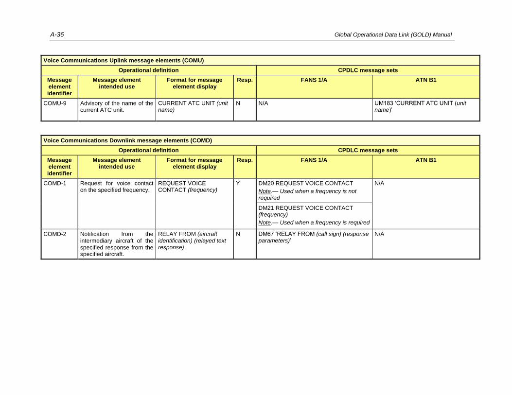
A-36 Global Operational Data Link (GOLD) Manual
Voice Communications Uplink message elements (COMU)
Operational definition CPDLC message sets
Message element identifier
Message element intended use
Format for message element display
Resp. FANS 1/A ATN B1
COMU-9 Advisory of the name of the current ATC unit.
CURRENT ATC UNIT (unit name)
N N/A UM183 ‘CURRENT ATC UNIT (unit name)’
Voice Communications Downlink message elements (COMD)
Operational definition CPDLC message sets
Message element identifier
Message element intended use
Format for message element display
Resp. FANS 1/A ATN B1
COMD-1 Request for voice contact on the specified frequency.
REQUEST VOICE CONTACT (frequency)
Y DM20 REQUEST VOICE CONTACT
Note.— Used when a frequency is not required
N/A
DM21 REQUEST VOICE CONTACT (frequency)
Note.— Used when a frequency is required
COMD-2 Notification from the intermediary aircraft of the specified response from the specified aircraft.
RELAY FROM (aircraft identification) (relayed text response)
N DM67 ‘RELAY FROM (call sign) (response parameters)’
N/A

Appendix A A-37
A.4.8 Spacing Message Elements
Spacing Uplink message elements (SPCU)
Operational definition CPDLC message sets
Message element identifier
Message element intended use
Format for message element display
Resp. FANS 1/A ATN B1
SPCU-1 ATS acknowledgement for the pilot use of the in-trail procedure when the ITP aircraft is behind the reference aircraft. This message element is always concatenated with a vertical clearance.
ITP BEHIND (aircraft identification)
N UM169 ‘ITP BEHIND (aircraft identification)’
Note.— R response attribute.
N/A
SPCU-2 ATS acknowledgement for the pilot use of the in-trail procedure when the ITP aircraft is ahead of the reference aircraft. This message element is always concatenated with a vertical clearance.
ITP AHEAD OF (aircraft identification)
N UM169 ‘ITP AHEAD OF (aircraft identification)’
Note.— R response attribute.
N/A
SPCU-3 ATS acknowledgement for the pilot use of the in-trail procedure when the ITP aircraft is behind both reference aircraft. This message element is always concatenated with a vertical clearance.
ITP BEHIND (aircraft identification) AND BEHIND (aircraft identification)
N UM169 ‘ITP BEHIND (aircraft identification) AND BEHIND (aircraft identification)’
Note.— R response attribute.
N/A
SPCU-4 ATS acknowledgement for the pilot use of the in-trail procedure when the ITP aircraft is ahead of both reference aircraft. This message element is always concatenated with a vertical clearance.
ITP AHEAD OF (aircraft identification) AND AHEAD OF (aircraft identification)
N UM169 ‘ITP AHEAD OF (aircraft identification) AND AHEAD OF (aircraft identification)’
Note.— R response attribute.
N/A

A-38 Global Operational Data Link (GOLD) Manual
Spacing Uplink message elements (SPCU)
Operational definition CPDLC message sets
Message element identifier
Message element intended use
Format for message element display
Resp. FANS 1/A ATN B1
SPCU-5 ATS acknowledgement for the pilot use of the in-trail procedure when the ITP aircraft is behind one reference aircraft and ahead of one reference aircraft. This message element is always concatenated with a vertical clearance.
ITP BEHIND (aircraft identification) AND AHEAD OF (aircraft identification)
N UM169 ‘ITP BEHIND (aircraft identification) AND AHEAD OF (aircraft identification)’
Note.— R response attribute.
N/A
Spacing Downlink message elements (SPCD)
Operational definition CPDLC message sets
Message element identifier
Message element intended use
Format for message element display
Resp. FANS 1/A ATN B1
SPCD-1 Advisory indicating that the pilot has the ITP equipment, and provides the specified distance to the reference aircraft, including aircraft identification. This message element is always concatenated with a vertical request.
ITP (specified distance) BEHIND (aircraft identification)
N DM67 ‘ITP (distance) BEHIND (aircraft identification)’
N/A
SPCD-2 Advisory indicating that the pilot has the ITP equipment, and provides the specified distance from the reference aircraft, including aircraft identification. This message element is always concatenated with a vertical request.
ITP (specified distance) AHEAD OF (aircraft identification)
N DM67 ‘ITP (distance) AHEAD OF (aircraft identification)’
N/A
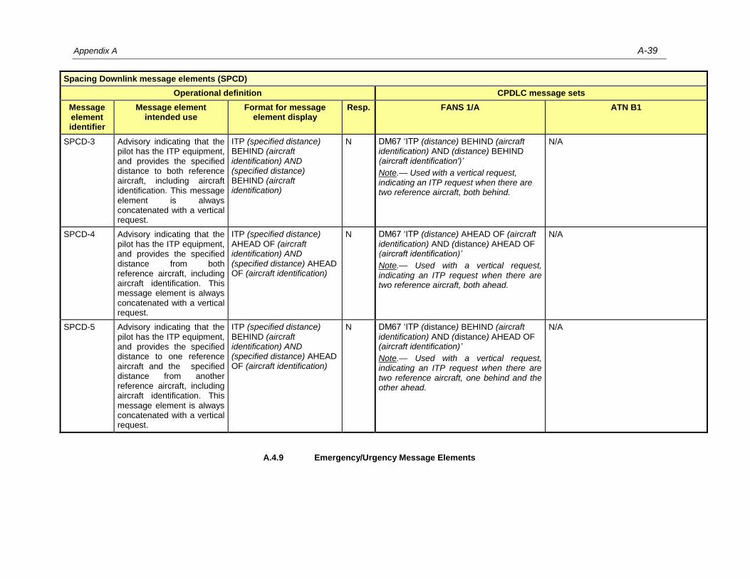
Appendix A A-39
Spacing Downlink message elements (SPCD)
Operational definition CPDLC message sets
Message element identifier
Message element intended use
Format for message element display
Resp. FANS 1/A ATN B1
SPCD-3 Advisory indicating that the pilot has the ITP equipment, and provides the specified distance to both reference aircraft, including aircraft identification. This message element is always concatenated with a vertical request.
ITP (specified distance) BEHIND (aircraft identification) AND (specified distance) BEHIND (aircraft identification)
N DM67 ‘ITP (distance) BEHIND (aircraft identification) AND (distance) BEHIND (aircraft identification')’
Note.— Used with a vertical request, indicating an ITP request when there are two reference aircraft, both behind.
N/A
SPCD-4 Advisory indicating that the pilot has the ITP equipment, and provides the specified distance from both reference aircraft, including aircraft identification. This message element is always concatenated with a vertical request.
ITP (specified distance) AHEAD OF (aircraft identification) AND (specified distance) AHEAD OF (aircraft identification)
N DM67 ‘ITP (distance) AHEAD OF (aircraft identification) AND (distance) AHEAD OF (aircraft identification)’
Note.— Used with a vertical request, indicating an ITP request when there are two reference aircraft, both ahead.
N/A
SPCD-5 Advisory indicating that the pilot has the ITP equipment, and provides the specified distance to one reference aircraft and the specified distance from another reference aircraft, including aircraft identification. This message element is always concatenated with a vertical request.
ITP (specified distance) BEHIND (aircraft identification) AND (specified distance) AHEAD OF (aircraft identification)
N DM67 ‘ITP (distance) BEHIND (aircraft identification) AND (distance) AHEAD OF (aircraft identification)’
Note.— Used with a vertical request, indicating an ITP request when there are two reference aircraft, one behind and the other ahead.
N/A
A.4.9 Emergency/Urgency Message Elements

A-40 Global Operational Data Link (GOLD) Manual
Emergency/Urgency Uplink message elements (EMGU)
Operational definition CPDLC message sets
Message element identifier
Message element intended use
Format for message element display
Resp. FANS 1/A ATN B1
EMGU-1 Request to provide the fuel remaining (time) and the number of persons on board.
REPORT ENDURANCE AND PERSONS ON BOARD
Y UM131 REPORT REMAINING FUEL AND SOULS ON BOARD
Note.— NE response attribute.
N/A
EMGU-2 Instruction to immediately comply with the associated instruction to avoid imminent situation.
IMMEDIATELY N Used in combination with LVLU-6 and LVLU-9, which is implemented in FANS 1/A as:
UM38 IMMEDIATELY CLIMB TO (altitude)
UM39 IMMEDIATELY DESCEND TO (altitude)
N/A
EMGU-3 Request to confirm an ADS-C indicated emergency.
CONFIRM ADS-C EMERGENCY
A/N UM169 ‘CONFIRM ADS-C EMERGENCY’
Note.— R response attribute.
N/A
Emergency/Urgency Downlink message elements (EMGD)
Operational definition CPDLC message sets
Message element identifier
Message element intended use
Format for message element display
Resp. FANS 1/A ATN B1
EMGD-1 Indication of an urgent situation.
PAN PAN PAN Y DM55 PAN PAN PAN
Note.— N response attribute.
N/A
EMGD-2 Indication of an emergency situation.
MAYDAY MAYDAY MAYDAY
Y DM56 MAYDAY MAYDAY MAYDAY
Note.— N response attribute.
N/A
EMGD-3 Report indicating fuel remaining (time) and number of persons on board.
(remaining fuel)
ENDURANCE AND (persons on board) PERSONS ON BOARD
Y DM57 (remaining fuel) OF FUEL REMAINING AND (remaining souls) SOULS ON BOARD
Note.— N response attribute.
N/A
EMGD-4 Indication that the emergency situation is cancelled.
CANCEL EMERGENCY Y DM58 CANCEL EMERGENCY
Note.— N response attribute.
N/A

Appendix A A-41
A.4.10 Standard Response Message Elements
Standard Response Uplink message elements (RSPU)
Operational definition CPDLC message sets
Message element identifier
Message element intended use
Format for message element display
Resp. FANS 1/A ATN B1
RSPU-1 Indication that the message cannot be complied with.
UNABLE N UM0 UNABLE UM0 UNABLE
RSPU-2 Indication that the message will be responded to shortly.
STANDBY N UM1 STANDBY UM1 STANDBY
RSPU-3 Indication that a long term delay in response can be expected.
REQUEST DEFERRED N UM2 REQUEST DEFERRED N/A
RSPU-4 Indication that the message is received.
ROGER N UM3 ROGER
UM3 ROGER
UM169 ‘ROGER MAYDAY’
Note 1.— R response attribute.
Note 2.— Used to acknowledge emergency downlink reports.
UM169 ‘ROGER PAN’
Note 1.— R response attribute.
Note 2.— Used to acknowledge urgency downlink reports.
RSPU-5 Indication that ATC is responding positively to the message.
AFFIRM N UM4 AFFIRM UM4 AFFIRM
RSPU-6 Indication that ATC is responding negatively to the message.
NEGATIVE N UM5 NEGATIVE UM5 NEGATIVE
RSPU-7 Indication that the request has been forwarded to the next control unit.
REQUEST FORWARDED N UM169 ‘REQUEST FORWARDED’
Note.— R response attribute.
UM211 REQUEST FORWARDED

A-42 Global Operational Data Link (GOLD) Manual
Standard Response Uplink message elements (RSPU)
Operational definition CPDLC message sets
Message element identifier
Message element intended use
Format for message element display
Resp. FANS 1/A ATN B1
RSPU-8 Request to confirm the referenced request since the initial request was not understood. The request should be clarified and resubmitted.
CONFIRM REQUEST N UM143 CONFIRM REQUEST N/A
Standard Response Downlink message elements (RSPD)
Operational definition CPDLC message sets
Message element identifier
Message element intended use
Format for message element display
Resp. FANS 1/A ATN B1
RSPD-1 Indication that the instruction is understood and will be complied with.
WILCO N DM0 WILCO DM0 WILCO
RSPD-2 Indication that the instruction cannot be complied with.
UNABLE N DM1 UNABLE DM1 UNABLE
RSPD-3 Indication that the message will be responded to shortly.
STANDBY N DM2 STANDBY DM2 STANDBY
RSPD-4 Indication that the message is received.
ROGER N DM3 ROGER
Note.— ROGER is the only correct response to an uplink free text message.
DM3 ROGER
RSPD-5 Indication of a positive response to a message.
AFFIRM N DM4 AFFIRM DM4 AFFIRM
RSPD-6 Indication of a negative response to a message.
NEGATIVE N DM5 NEGATIVE DM5 NEGATIVE

Appendix A A-43
A.4.11 Supplemental Message Elements
Supplemental Uplink message elements (SUPU)
Operational definition CPDLC message sets
Message element identifier
Message element intended use
Format for message element display
Resp. FANS 1/A ATN B1
SUPU-1 Indication that the associated instruction is to be executed when the flight crew is ready.
WHEN READY N UM164 WHEN READY N/A
SUPU-2 Indication that the associated message is issued due to the specified reason.
DUE TO (specified reason uplink)
N UM166 DUE TO TRAFFIC
N/A
UM167 DUE TO AIRSPACE RESTRICTION
SUPU-3 Instruction to execute the associated instruction at the aircraft’s best performance rate.
EXPEDITE N Used in combination with LVLU-6, which is implemented in FANS 1/A as:
UM36 EXPEDITE CLIMB TO (altitude).
N/A
SUPU-4 Indication that the associated instruction is either a revision to a previously issued instruction or is different from the requested clearance.
REVISED (revision reason[O])
N UM170 ‘REVISED (revision reason[O])’
Note.— R response attribute.
N/A
SUPU-5 Indication that the associated instruction is to be executed at the earliest point when the flight crew is able.
WHEN ABLE N N/A
Note.— This message element is part of UM75.
N/A

A-44 Global Operational Data Link (GOLD) Manual
Supplemental Downlink message elements (SUPD)
Operational definition CPDLC message sets
Message element identifier
Message element intended use
Format for message element display
Resp. FANS 1/A ATN B1
SUPD-1 Indication that the associated message is issued due to specified reason.
DUE TO (specified reason downlink)
N DM65 DUE TO WEATHER
DM65 DUE TO WEATHER
DM66 DUE TO AIRCRAFT PERFORMANCE
DM66 DUE TO AIRCRAFT PERFORMANCE
A.4.12 Free Text Message Elements
Free Text Uplink message elements (TXTU)
Operational definition CPDLC message sets
Message element identifier
Message element intended use
Format for message element display
Resp. FANS 1/A ATN B1
TXTU-1 (free text)
Note.— M alert attribute.
R UM169 (free text) UM203 (free text)
TXTU-2 (free text)
Note.— M alert attribute.
N UM169 (free text)
Note.— R response attribute.
UM183 (free text)
TXTU-3 (free text)
Note.— N alert attribute.
N UM169 (free text)
Note.— R response attribute.
N/A
TXTU-4 (free text)
Note.— M alert attribute.
W/U UM169 (free text)
Note.— R response attribute.
UM196 (free text)
TXTU-5 (free text)
Note.— M alert attribute.
A/N UM169 (free text)
Note.— R response attribute.
UM205 (free text)
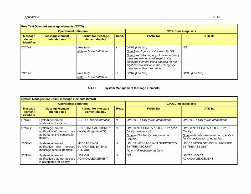
Appendix A A-45
Free Text Downlink message elements (TXTD)
Operational definition CPDLC message sets
Message element identifier
Message element intended use
Format for message element display
Resp. FANS 1/A ATN B1
TXTD-1 (free text)
Note.— M alert attribute..
Y DM68 (free text)
Note 1.— Urgency or Distress Alr (M)
Note 2.— Selecting any of the emergency message elements will result in this message element being enabled for the flight crew to include in the emergency message at their discretion.
N/A
TXTD-2 (free text)
Note.— M alert attribute..
N DM67 (free text) DM98 (free text)
A.4.13 System Management Message Elements
System Management Uplink message elements (SYSU)
Operational definition CPDLC message sets
Message element identifier
Message element intended use
Format for message element display
Resp. FANS 1/A ATN B1
SYSU-1 System-generated notification of an error.
ERROR (error information) N UM159 ERROR (error information) UM159 ERROR (error information)
SYSU-2 System-generated notification of the next data authority or the cancellation thereof.
NEXT DATA AUTHORITY (facility designation[O])
N UM160 NEXT DATA AUTHORITY (icao facility designation)
Note.— The facility designation is required.
UM160 NEXT DATA AUTHORITY (facility)
Note.— Facility parameter can specify a facility designation or no facility.
SYSU-3 System-generated notification that received message is not supported.
MESSAGE NOT SUPPORTED BY THIS ATC UNIT
N UM169 ‘MESSAGE NOT SUPPORTED BY THIS ATC UNIT’
Note.— R response attribute.
UM162 MESSAGE NOT SUPPORTED BY THIS ATS UNIT
SYSU-4 System-generated notification that the received is acceptable for display.
LOGICAL ACKNOWLEDGEMENT
N N/A UM227 LOGICAL ACKNOWLEDGEMENT

A-46 Global Operational Data Link (GOLD) Manual
System Management Uplink message elements (SYSU)
Operational definition CPDLC message sets
Message element identifier
Message element intended use
Format for message element display
Resp. FANS 1/A ATN B1
SYSU-5 System-generated message indicating that requests for logical acknowledgements are not permitted.
USE OF LOGICAL ACKNOWLEDGEMENT PROHIBITED
N N/A UM233 USE OF LOGICAL ACKNOWLEDGEMENT PROHIBITED
Note.— ATN B1 ground systems may not use UM (as par ETSI CS) since the use of LACK is required.
SYSU-6 Advisory providing the maximum one-way uplink message transmission delay.
LATENCY TIME VALUE (latency value)
N UM169 ‘SET MAX UPLINK DELAY VALUE TO (delayed message parameter) SECONDS’
Note 1.— R response attribute.
Note 2.— On FANS 1/A aircraft, this message requires specific action from the flight crew to manually set the latency value.
N/A
SYSU-7 Indication that the received message has a latency greater than the requirement.
MESSAGE RECEIVED TOO LATE, RESEND MESSAGE OR CONTACT BY VOICE
N N/A UM159 ERROR (error information) +
UM183 ‘DOWNLINK DELAYED USE – VOICE’
Note.— The error information is set to the value (2).
System Management Downlink message elements (SYSD)
Operational definition CPDLC message sets
Message element identifier
Message element intended use
Format for message element display
Resp. FANS 1/A ATN B1
SYSD-1 System-generated notification of an error.
ERROR (error information) N DM62 ERROR (error information) DM62 ERROR (error information)
SYSD-2 System-generated notification that the received message is acceptable for display.
LOGICAL ACKNOWLEDGEMENT
N N/A DM100 LOGICAL ACKNOWLEDGEMENT

Appendix A A-47
System Management Downlink message elements (SYSD)
Operational definition CPDLC message sets
Message element identifier
Message element intended use
Format for message element display
Resp. FANS 1/A ATN B1
SYSD-3 System-generated rejection of any CPDLC message sent from a ground facility that is not the current data authority.
NOT CURRENT DATA AUTHORITY
N DM63 NOT CURRENT DATA AUTHORITY
DM63 NOT CURRENT DATA AUTHORITY
SYSD-4 System-generated notification that the ground facility is now the current data authority.
CURRENT DATA AUTHORITY
N N/A DM99 CURRENT DATA AUTHORITY
SYSD-5 System-generated notification that the ground system is not designated as the next data authority (NDA), indicating the identity of the Current Data Authority. Identity of the Next Data Authority, if any, is also reported.
NOT AUTHORIZED NEXT DATA AUTHORITY (facility designation)( facility designation[O])
N DM64 (ICAO facility designation)
Note.— Use by FANS 1/A aircraft in B1 environments.
DM107 NOT AUTHORIZED NEXT DATA AUTHORITY
Note.— CDA and NDA cannot be provided.
SYSD-6 Indication that the received message has a latency greater than the requirement.
MESSAGE RECEIVED TOO LATE, RESEND MESSAGE OR CONTACT BY VOICE
N DM67 ‘MESSAGE RECEIVED TOO LATE, RESEND MESSAGE OR CONTACT BY VOICE’
Note.— Sent with DM62.
DM 98 ‘MESSAGE RECEIVED TOO LATE, RESEND MESSAGE OR CONTACT BY VOICE’
Note.— Sent with DM62.
SYSD-7 System-generated notification that the aircraft is in the inhibited state.
AIRCRAFT CPDLC INHIBITED
N N/A DM 98 ‘AIRCRAFT CPDLC INHIBITED’

A-48 Global Operational Data Link (GOLD) Manual
A.5 Message elements parameters
The following table provides descriptions for high-level variables used in the message elements and highlights main differences with variables used in FANS
1/A (+) and ATN B1 message sets. Range and resolution variations are not documented in this table but are defined in interoperability standards.
Variable description Messages sets variables
Variable Description FANS 1/A ATN B1
aircraft identification Provides the aircraft identification identical to, or the
code equivalent of, the aircraft call sign as provided in
the Item 7 of the flight plan.
aircraft identification aircraft identification
aircraft type Specifies the aircraft type when known. N/A N/A
altimeter setting Specifies an altimeter in inches of mercury or
hectopascals.
altimeter altimeter
arrival approach data Specifies at least one of the following: destination
airport, arrival runway, arrival procedure, or approach
procedure.
Provided as a component of the route clearance variable
Provided as a component of the route clearance variable
ATIS code Specifies the current ATIS code. atis code N/A
ATS route designator Specifies the 2-7 character name of the route. airway identifier ATS route designator
along track waypoint Specifies point in the route specified as relative
distance for another waypoint on the route. May
include speed and level constraints at this point.
ATW along track waypoint ATW along track waypoint
clearance limit Specifies the farthest cleared point as a position. N/A N/A
clearance name Specifies a 2-14 character name of a clearance, usually
specifying the name of an unpublished procedure or
route.
N/A N/A
clearance type Specifies the type of clearance as: approach,
departure, further, startup, pushback, taxi, or oceanic.
clearance type clearance type
degrees Specifies direction in terms of degrees as either
degrees from magnetic north or degrees from true
north.
degrees degrees

Appendix A A-49
Variable description Messages sets variables
Variable Description FANS 1/A ATN B1
departure clearance Specifies the required departure clearance information
as one or more of the following:
departure airport,
departure runway,
cleared to position,
departure route data specified as either
o the route is as filed, or
o a SID and optionally that the rest of the
route after the SID is as filed (i.e., then as
filed)
departure level, and any constraint on the level
(duration or until position)
expected level and any constraint on the level
(duration or until position)
departure speed and any constraint on the speed
(duration or until position)
departure heading in degrees,
indication when no delay is expected,
target start-up approval time,
arrival and/or approach procedures including any
special instructions,
SSR code,
ATIS code, and/or
departure frequency.
departure clearance N/A
departure data Specifies the departure data as at least one of the
following: departure airport (airport departure),
departure runway (runway departure), or departure
procedure (procedure departure).
Provided as a component of the route
clearance variable
Provided as a component of the route
clearance variable
deviation type Specifies the deviation type as a lateral position, level or speed.
N/A N/A
direction Specifies direction as:
Left, Right, Either Side
North, South, East, West,
Northeast, Northwest, Southeast, or Southwest
direction direction

A-50 Global Operational Data Link (GOLD) Manual
Variable description Messages sets variables
Variable Description FANS 1/A ATN B1
error information Specifies reason for error as: unrecognized message
reference number, insufficient resources, checksum
failure, or undefined.
error information error information
ETP time Specifies the estimated time (hours and minutes) of
passing opposite direction traffic.
N/A N/A
facility designation Specifies the ICAO location indicator for a facility. facility designation facility designation
facility function Specifies the function of the facility as: center,
approach, tower, final, ground control, clearance
delivery, departure, control, radio, apron, information,
ramp, flight watch, AOC/company, de-icing, or flight
service.
facility function Note.— the following functions cannot be indicated: radio, apron, information, ramp, flight watch, AOC/company, de-icing, or flight service
facility function Note.— the following functions cannot be indicated: apron, information, ramp, flight watch, AOC/company, de-icing, or flight service
free text Provides additional information in a non-structured
format.
free text free text
frequency Specifies the frequency as a HF, VHF, or UHF
frequency, or as a telephone number.
frequency frequency
hold at waypoint Specifies a hold instruction providing the position of the hold as position and additionally any or all of the following: hold speed low, waypoint level constraint, hold speed high, a left or right hold, degrees, time a further clearance is expected, and leg type.
hold at waypoint Note.— An along track waypoint cannot be provided.
hold at waypoint Note.— An along track waypoint cannot be provided.
latency value Provides the CPDLC message latency value in
seconds.
N/A N/A
lateral deviation Specifies the lateral deviation as the permitted distance
left, right, or either side from the cleared route in
nautical miles or kilometers.
distance offset direction N/A
latitude longitude Specifies the latitude and longitude in degrees, minutes,
tenths of minutes and direction (north, south, east or
west).
latitude longitude latitude longitude
leg type Specifies a holding leg as distance (tenths of nautical
miles or tenths of kilometers) or time (tenths of
minutes).
leg type leg type
level Specifies a level as a single or block level in feet,
meters, or flight levels.
level Note.— The level cannot be expressed in Level Meters or Level Flight Level Metric
level Note.— The level cannot be expressed in Level Meters or Level Flight Level Metric

Appendix A A-51
Variable description Messages sets variables
Variable Description FANS 1/A ATN B1
level single Specifies a single level in feet, meters, or flight levels. N/A
Note.— The level parameter is used.
N/A
Note.— The level parameter is used.
named instruction Specifies a named instruction as either a clearance
name or a procedure name.
N/A
Note.— The procedure name parameter is used.
procedure name Note.— The procedure name parameter is used.
number of degrees Provides the number of degrees. N/A N/A
Note.— The degrees parameter is used.
number of minutes Provides the number of minutes (time). N/A N/A
persons on board Provides the number of persons on board or indicates
that the number is unknown.
remainingsouls N/A
place bearing distance Specifies a place bearing and a distance in nautical
miles or kilometers.
place bearing distance place bearing distance
place bearing Specifies a published identifier and degrees. place bearing place bearing
position Specifies a position as a:
published identifier,
latitude longitude, or
place bearing distance
position
Note.— The latitude and longitude are
optional.
position
Note.— The latitude and longitude are
optional.
position report Provides information similar to a voice position report as
defined in ICAO Doc 4444, Paragraph 4.11.2.
N/A N/A
procedure name Specifies a procedure name by specifying a procedure
type (departure, arrival, or approach) and identifier (1-
20 characters), and when applicable:
the runway, and/or
any required procedure transition, and/or
any required additional information about the
procedure.
procedure name
Note.— The runway cannot be provided
procedure name
Note.— The runway cannot be provided
published identifier Specifies the published identifier name (1-5 characters)
and associated latitude and longitude (degrees,
minutes, seconds).
published identifier
Note.— Provision of Latitude Longitude
is optional.
published identifier
Note.— Provision of Latitude Longitude is
optional.
relay text Specifies the information to be relayed to the specified
aircraft as free text.
N/A N/A
relayed text response Specifies information relayed from the specified aircraft
as free text.
N/A N/A
remaining fuel Specifies remaining fuel as time in seconds. remaining fuel N/A

A-52 Global Operational Data Link (GOLD) Manual
Variable description Messages sets variables
Variable Description FANS 1/A ATN B1
revision reason Specifies the reason(s) for the clearance revision as
any or all of the following: level change, a speed
change, a route change at a specified position, a route
change at multiple waypoints, an entry point change, a
clearance limit change, a named instruction change,
and/or a ground location change.
N/A N/A
en-route data Specifies the cleared route of flight for up to 128
waypoints with positional information (route
information), including for each waypoint as required,
level constraint, speed constraint, required time of
arrival, hold instruction and flyby or fly over information
(route information additional). A clearance limit may
be included. A locally defined named instruction may
also be included.
Provided as a component of the route clearance variable .
Provided as a component of the route clearance variable
route information additional
Specifies any or all of the following:
1 to 8 along track waypoint,
1 to 8 hold at waypoint,
1 to 32 waypoint speed level,
1 to 32 required time arrival.
route information additional route information additional
route information Specifies route information as one of:
published identifier,
latitude longitude,
place bearing distance, or
ATS route designator.
route information route information
required time arrival For the specified position, provides the required time of
arrival (hours, minutes (seconds (optional)), optionally
any tolerance around the RTA, and indicates the RTA
as at, before, or after the specified time.
RTA required time arrival Note.— The seconds cannot be specified.
RTA required time arrival Note.— The seconds cannot be specified.
runway Specifies a runway by direction and configuration (left,
right, center, or none).
runway runway
runway Specifies a runway by direction and configuration (left,
right, centre, or none).
N/A N/A

Appendix A A-53
Variable description Messages sets variables
Variable Description FANS 1/A ATN B1
specified deviation Specifies the deviation from the route as a specified
distance or number of degrees.
distance offset
Note.— A number of degrees cannot be
provided.
N/A
specified distance Specifies distance in nautical miles or kilometers. distance offset or distance (ITP) specified distance
specified reason downlink
Specifies the reason for the associated message as
weather or aircraft performance.
N/A N/A
specified reason uplink Specifies the reason for the associated message as:
opposite direction traffic, same direction traffic,
converging traffic, crossing traffic, or diverging traffic,
airspace restriction, invalid oceanic entry point, no flight
plan held, oceanic clearance request received too late.
N/A N/A
SSR code Specifies the beacon code as 4 octal digits. beacon code code
speed Specifies speed in English or metric units as indicated,
true, ground, or Mach speed.
speed speed
speed types Specifies the speed as a minimum or maximum and 1
to 2 speed type(s), where the speed type indicates
speed as: indicated, true, ground, Mach, approach,
cruise, or present.
N/A N/A
time Specifies time in hours and minutes. time time
traffic description Specifies a description of traffic significant to a flight by
providing any or all of the following information: the
aircraft identification, the aircraft type, the current flight
level of the aircraft, the location relative to the given
aircraft as the distance (if known) above or below, and
indicates when known that the traffic is, opposite
direction, same direction, converging, crossing, or
diverging from the given aircraft.
N/A N/A
traffic location Specifies the location for opposite direction traffic indicating if the traffic is above or below the given aircraft, and when known, provides the vertical distance in feet or meters.
N/A N/A
traffic visibility Indicates the traffic visibility as: “sighted and passed”,
“sighted”, or “not sighted”.
N/A N/A
unit name Specifies the unit name by providing any or all of the
following: facility name, facility designation, or facility
function as appropriate.
unit name Note.— The facility designation and facility function are always provided.
unit name Note.— The facility designation and facility function are always provided.

A-54 Global Operational Data Link (GOLD) Manual
Variable description Messages sets variables
Variable Description FANS 1/A ATN B1
vertical rate Specifies the vertical rate as feet/minute or
meters/minute.
vertical rate vertical rate Note.— The vertical rate expressed in meters/minute cannot be provided.
waypoint speed level Specifies the speed and level constraints on the
specified position.
waypoint speed altitude
Note.— The speed qualifier cannot be
provided.
waypoint speed level
Note.— The speed qualifier cannot be
provided.
A.6 Message elements recommended not to use
A.6.1 FANS 1/A Uplink message elements
Message Element Justification
UM49 CROSS (position) AT AND MAINTAIN (altitude) Avoid use of this message due to inability of aircraft automation to maintain the altitude restriction.
UM62 AT (time) CROSS (position) AT AND MAINTAIN (altitude)
UM85 EXPECT (route clearance) Avoid use of this message element due to potential misinterpretation.
UM86 AT (position) EXPECT (route clearance)
UM87 EXPECT DIRECT TO (position)
UM88 AT (position) EXPECT DIRECT TO (position)
UM89 AT (time) EXPECT DIRECT TO (position)
UM90 AT (altitude) EXPECT DIRECT TO (position)
UM162 SERVICE UNAVAILABLE
UM6 EXPECT (altitude)
UM11 EXPECT CRUISE CLIMB AT (time)
UM12 EXPECT CRUISE CLIMB AT (position)
UM13 AT (time) EXPECT CLIMB TO (altitude)
UM14 AT (position) EXPECT CLIMB TO (altitude)
UM15 AT (time) EXPECT DESCENT TO (altitude)
UM16 AT (position) EXPECT DESCENT TO (altitude)
UM17 AT (time) EXPECT CRUISE CLIMB TO (altitude)

Appendix A A-55
Message Element Justification
UM18 AT (position) EXPECT CRUISE CLIMB TO (altitude)
UM33 CRUISE (altitude)
UM34 CRUISE CLIMB TO (altitude)
UM35 CRUISE CLIMB ABOVE (altitude)
UM40 IMMEDIATELY STOP CLIMB AT (altitude)
UM41 IMMEDIATELY STOP DESCENT AT (altitude)
UM175 REPORT REACHING (altitude)
UM42 EXPECT TO CROSS (position) AT (altitude)
UM43 EXPECT TO CROSS (position) AT OR ABOVE (altitude)
UM44 EXPECT TO CROSS (position) AT OR BELOW (altitude)
UM45 EXPECT TO CROSS (position) AT AND MAINTAIN (altitude)
UM103 AT (time) EXPECT (speed) TO (speed)
UM104 AT (position) EXPECT (speed) TO (speed)
UM105 AT (altitude) EXPECT (speed) TO (speed)
UM165 THEN
UM235 ROGER 7500
UM168 DISREGARD Not operationally required.
Note. – These messages have been excluded from future B2 implementation.
UM176 MAINTAIN OWN SEPARATION AND VMC
UM152 WHEN CAN YOU ACCEPT (specified distance) (direction) OFFSET
UM115 DO NOT EXCEED (speed)
UM182 CONFIRM ATIS CODE
UM169 ‘TRANSMIT ADS-B IDENT’ Use of SQUAWK IDENT is recommended.
UM169 ‘IDENTIFICATION TERMINATED’ Use of SURVEILLANCE SERVICE TERMINATED is recommended.
UM132 CONFIRM POSITION Use of ADS-C is recommended.
UM133 CONFIRM ALTITUDE
UM138 CONFIRM TIME OVER REPORTED WAYPOINT.
UM139 CONFIRM REPORTED WAYPOINT
UM140 CONFIRM NEXT WAYPOINT
UM141 CONFIRM NEXT WAYPOINT ETA.

A-56 Global Operational Data Link (GOLD) Manual
Message Element Justification
UM142 CONFIRM ENSUING WAYPOINT
UM146 REPORT GROUND TRACK
UM181 REPORT DISTANCE (to/from) (position)
UM145 CONFIRM HEADING
UM177 AT PILOTS DISCRETION Not globally accepted. See Appendix B, paragraph 3.2.1 for its use.
A.6.2 FANS 1/A Downlink message elements
Message Element Justification
DM69 REQUEST VMC DESCENT Avoid use of this message element due to potential misinterpretation.
DM75 AT PILOTS DISCRETION
DM 67 ‘WHEN CAN WE EXPECT DESCENT TO (altitude)’ Avoid use of this message due to potential misinterpretation of subsequent response. Use of LVLD-6 WHEN CAN WE EXPECT HIGHER LEVEL and LVLD-7 WHEN CAN WE LOWER HIGHER LEVEL is recommended.
DM67 ‘WHEN CAN WE EXPECT CLIMB TO (altitude)’
DM74 REQUEST TO MAINTAIN OWN SEPARATION AND VMC Not operationally required.
Note. – These messages have been excluded from future B2 implementation.
DM8 REQUEST CRUISE CLIMB TO (altitude)
DM54 WHEN CAN WE EXPECT CRUISE CLIMB TO (altitude)
DM72 REACHING (altitude)
DM79 ATIS (atis code)
DM67 ‘MONITORING (unit name) (frequency)’
DM16 AT (position) REQUEST OFFSET (specified distance) (direction) OF ROUTE
DM17 AT (time) REQUEST OFFSET (specified distance) (direction) OF ROUTE
DM26 REQUEST WEATHER DEVIATION TO (position) VIA (route clearance)
DM33 PRESENT POSITION (position) Use of ADS-C is recommended.
DM36 PRESENT GROUND TRACK (degrees)
DM42 NEXT WAYPOINT (position)
DM43 NEXT WAYPOINT ETA (time)
DM44 ENSUING WAYPOINT (position)

Appendix A A-57
DM45 REPORTED WAYPOINT (position)
DM46 REPORTED WAYPOINT (time)
DM78 AT (time) (distance) (tofrom) (position)
DM32 PRESENT ALTITUDE (altitude)
DM35 PRESENT HEADING (degrees)
DM19 REQUEST (speed) TO (speed) Use of SPDD-1 REQUEST (speed) is recommended.
DM50 WHEN CAN WE EXPECT (speed) TO (speed)
A.6.3 ATN B1 Uplink message element
Message Element Justification
UM165 THEN Avoid use of this message element due to potential misinterpretation.
A.6.4 ATN B1 Downlink message element
Message Element Justification
DM89 MONITORING (unit name) (frequency) Not operationally required.
Note. – This message has been excluded from future B2 implementation


APPENDIX B
REGIONAL/STATE-SPECIFIC INFORMATION
B.1 GENERAL
B.1.1 This Appendix provides Regional/State specific information grouped per ICAO Regions pertaining to the
data link operations.
B.1.2 For CPDLC and ADS-C columns provided in the regional data link service tables, O=operational, T=trial,
and N=not available.
B.2 EUROPEAN (EUR) REGION
B.2.1 ADMINISTRATIVE PROVISIONS RELATED TO DATA LINK OPERATIONS
B.2.1.1 ANSP service provision
B.2.1.1.1 Table B-EUR-1 lists the flight information regions (FIRs) and Upper flight information regions (UIRs),
where ATN B1 or FANS 1/A-ATN B1 data link service is provided and indicates Logon address, ATSU ACARS Address
(where applicable), the year of implementation (where available) and responsible regional coordinating group.
Note 1.— For foreseen implementation date and the CPDLC message set used by each State, refer to
the AIP/AIC concerned.
Note 2.— The ANSPs reflected in Table B-EUR-1 would need to equip in accordance with the published
amendment of the IR. 2015/315.
B.2.1.1.2 European regulations require ATN B1 data link services be provided above FL285, however individual
states are free to provide services below that level. Refer to the AIP of each state for details.
B.2.1.1.3 The use of CPDLC is conducted at the discretion of each responsible ACC and at the initiative of the flight
crew. CPDLC is used for routine exchanges during en-route operations in the upper airspace and is not for time-critical
situations. Communication exchanges by voice have priority over CPDLC exchanges at all times.

B-2 Global Operational Data Link (GOLD) Manual
Table B-EUR-1. Data link services by control area (CTA)
Control area (CTA)
CP
DL
C
AD
S-C
Logon address
ATSU ACARS Address
Coord Group
Remarks
Bucuresti FIR O N LRBB N/A TBD ATN B1
Budapest FIR O N LHCC N/A TBD ATN B1
Barcelona UIR O N LECB N/A TBD ATN B1
Bordeaux UAC
O N LFBB N/A TBD ATN B1
Brest UAC O N LFRR N/A TBD ATN B1
Brindisi FIR O N LIBB N/A TBD ATN B1
Canarias UIR O N GCCC N/A TBD ATN B1
Finland UIR O N EFIN N/A TBD ATN B1
only in the area south of 61°30’N
Geneva UIR O N LSAG N/A TBD ATN B1
Hellas UIR O N LGGG N/A TBD ATN B1
Kobenhavn FIR
O N EKDK N/A TBD ATN B1
Lisboa UIR O N LPPC LISACYA TBD ATN B1
FANS 1/A
Ljubljana FIR O N LJLA N/A TBD ATN B1
London UIR O O EGTT SOUCAYA TBD ATN B1
FANS 1/A.
Madrid UIR O N LECM N/A TBD ATN B1
Magadan (Russia)
O O GDXB TBD FANS 1/A
Malta UIR O N LMMM N/A TBD ATN B1
MUAC
Amsterdam FIR
Brussels FIR
Hannover FIR
O O EDYY MSTEC7X TBD ATN B1
FANS 1/A
Marseille UAC O N LFMM N/A TBD ATN B1
Milano ACC O N LIMM N/A TBD ATN B1
Nicosia FIR O N LCCC N/A TBD ATN B1
Oslo FIR O N ENOS N/A TBD ATN B1
FANS 1/A
Padova ACC O N LIPP N/A TBD ATN B1
Paris UAC O N LFFF N/A TBD ATN B1
Praha FIR O N LKAA N/A TBD ATN B1
Reims UAC O N LFEE N/A TBD ATN B1

Appendix B B-3
Control area (CTA)
CP
DL
C
AD
S-C
Logon address
ATSU ACARS Address
Coord Group
Remarks
Rhein UIR O N EDUU N/A TBD ATN B1
Riga UIR O N EVRR N/A TBD ATN B1
Roma FIR O N LIRR N/A TBD ATN B1
Scottish UIR O O EGPX PIKCAYA TBD ATN B1
FANS 1/A
Shannon UIR O O EISN TBD TBD ATN B1
FANS 1/A
Sofia FIR O N LBSR N/A TBD ATN B1
Sweden UIR O N ESAA N/A TBD ATN B1
Only in the area south of 61°30′N
Tallinn UIR O N EETT N/A TBD ATN B1
Vilnius UIR O N EYVC N/A TBD ATN B1
Warszaw FIR O N EPWW N/A TBD ATN B1
Wien FIR O N LOVV N/A TBD ATN B1
Zagreb FIR O N LDZO N/A TBD ATN B1
Zurich UIR O N LSAZ N/A TBD ATN B1
B.2.1.2 EUR - NSAP address registry
B.2.1.2.1 In order to allow the air crew to perform a first LOGON with any of the participating ATN B1 ACCs,
Context Management application addressing information of the ATS Units involved in the ATN/OSI based Air/Ground
Data Link Communications, is required in the ATN avionics system.
B.2.1.2.2 The ATN NSAP addresses for all EUR Air Traffic Control Centres (ACCs) are published in EUR Doc 028 -
EUR NSAP Address Registry.
B.2.1.2.3 The focal point for the EUR NSAP Address Registry is the EUR/NAT ICAO Regional Office. All requests,
modifications and proposals concerning this document should be forwarded to: [email protected].
Note 1.— The ICAO EUR/NAT Office ensures that the information is forwarded to the appropriate working
groups (e.g. AFSG Planning Group).
Note 2.— The EUR NSAP Address Registry is available at the ICAO website:
http://www.icao.int/EURNAT/Pages/EUR-and-NAT-Document.aspx.
B.2.1.3 Flight plan provisions
B.2.1.3.1 In the EUR airspace where ATN B1 CPDLC is available and aircraft are equipped and capable ATN B1
CPDLC, J1 shall be included in Item 10a of the flight plan:
a) Operators of FANS 1/A – ATN B1 (independent or integrated) equipped aircraft shall insert one or
more of the appropriate indicators among J1 –J7 in Item 10a.

B-4 Global Operational Data Link (GOLD) Manual
b) For flights conducted wholly or partly in the EUR airspace where ATN B1 CPDLC is available but
for which the aircraft has been granted an exemption, the letter Z shall be included in Item 10A
and the indicator DAT/CPDLCX shall be included in Item18 of the flight plan.
B.2.1.3.2 For a flight operating based on a repetitive flight plan (RPL), during which the pilot intends to use CPDLC,
a modification message (CHG) shall be submitted to indicate that the flight is capable of, and authorized for CPDLC, in
accordance with paragraph 2.3.
B.2.1.3.3 When there is a change to the CPDLC capability status for a flight planned to operate in the area
specified in Table B-EUR-, the operator should send a modification message (CHG) with the appropriate indications in
the relevant items of the ICAO flight plan form, including any change to the aircraft address. A modification message for
the day of operation should be sent not earlier than 20 hours before the estimated off-block time.
B.2.1.4 Logon criteria
B.2.1.4.1 In addition to the logon FPL correlation criteria, described in paragraph 2.3, the CPDLC aircraft equipment
capabilities in Item 10a are also used as criterion for a successful logon. Absence of item J1 and/or one or more of the
items J2 to J7 in Item 10a will lead to a logon rejection.
B.2.1.5 Lack Timer
B.2.1.5.1 Logical Acknowledgement (LACK) messages (downlink message element DM 100 and uplink message
element UM227) are used in ATN B1 based ACL and ACM message exchanges.
Note 1.— Ground systems do not request a LACK for the messages ERROR (UM159), Service
Unavailable (UM162) and LACK (UM227).
Note 2.— When a LACK is received after expiry of the LACK timer, the LACK may be discarded.
B.2.2 CONTROLLER PROCEDURES
B.2.2.1 Reverting from CPDLC to voice
B.2.2.1.1 The following circumstances describe potential situations where the controller should revert to voice to
instruct the pilot to ignore the CPDLC message:
a) when it is required to clarify the meaning or the intent of any unexpected, inappropriate or ambiguous
CPDLC message;
b) whenever it is deemed necessary to ensure the timely execution of a clearance or instruction
previously issued by CPDLC; and
c) whenever corrective actions are required with respect to unintended clearances, instructions or
information that has been sent using CPDLC.
B.2.2.1.2 Controllers should be aware that once a message is sent via CPDLC, no means exist to cancel or to
recall that message.

Appendix B B-5
B.2.2.1.3 In case of reversion to voice, controllers should be aware of the possibility that the CPDLC message they
want the addressee to ignore may not be yet displayed to the addressee.
B.2.2.1.4 In that respect, the following actions should be taken by the addressee:
a) If response to the referred CPDLC message was sent, cancel any action initiated on the basis of the
initial CPDLC message and comply with the voice message;
b) If the referred message is not responded to or not displayed, let the dialogue close on time-out. Since
it may be possible to be asked to ignore a message that was not yet displayed, the controller/pilot
should take all measures to ensure that the message is no longer valid.
c) In case the controller/pilot has already received an operational response to the initial CPDLC
message, he/she shall use appropriate voice phrases to stop/cancel the actions of the addressee.
d) Whenever a system generates a time-out or an error for a CPDLC message, the controller should be
contacted.
B.2.2.1.5 Use of Free Text. In support of the recommendation in ED-110B/DO-280B on ‘free text’, some ANSPs do
not allow the controller to enter free text on the human-machine interface (HMI).
B.2.2.2 Preconditions for the operational exchange of CPDLC messages
B.2.2.2.1 “When CPDLC is transferred, the transfer of voice communications and CPDLC shall commence
concurrently” (Annex 10, Volume II, 8.2.9.6.1; PANS-ATM, 14.3.3.1).
B.2.2.2.2 The minimum conditions required for an operationally functional 2-way communication connection, is that
the aircraft is under the responsibility of the CDA (i.e. it has an active connection and the ATS unit has assumed the
control of the flight after initial voice contact establishment and a CPDLC message, indicating the name and function of
the current ATC unit, is received by the flight crew).
Note.— Additional local conditions (boundary proximity, etc.), which will vary from ATS unit to ATS unit,
may apply.
B.2.2.2.3 If an aircraft sends a request to an ATS unit before the minimum conditions have been fulfilled, the
request is rejected by the ground system. An error message is displayed to the flight crew ‘CPDLC TRANSFER NOT
COMPLETED -- REPEAT REQUEST’.
B.2.2.3 Uplink messages
B.2.2.3.1 Operational use of LACK
B.2.2.3.1.1 Each time the controller semds an operational message, the ATN B1 aircraft system returns a DM 100
logical acknowledgement (LACK).
B.2.2.3.1.2 The LACK timer value should be set by the ground system at 40 seconds.
B.2.2.3.1.3 If the ground system does not receive a LACK within 40 seconds, the controller will be notified.

B-6 Global Operational Data Link (GOLD) Manual
Note 1.— The ground system does not request a LACK for messages UM 157 (CHECK STUCK
MICROPHONE), UM 159 (ERROR), UM 162 (SERVICE UNAVAILABLE), UM 227 (LACK).
Note 2.— Local implementers may decide whether the controller is notified on the receipt of each LACK
(positive feedback) or is only notified upon a LACK time out (negative feedback).
Note 3.— When a LACK is received after expiry of the LACK timer, the LACK may be discarded.
B.2.2.3.2 UM 120 MONITOR (unitname) (frequency)
B.2.2.3.2.1 The UM 120 MONITOR message is not used for inter-ATSU and intra-ATSU flight transfers. This is
because controllers want to have the assurance that voice communication is established at "initial call" to the next sector
or ATS unit. Moreover, the “initial call” is used to communicate cleared level and passing level, to reconfirm clearance
previously given and to verify the accuracy of Mode-C at the first sector of the receiving ATS unit.
B.2.2.3.2.2 In response to UM 120 MONITOR, sent by the transferring ATS unit, DM 89 MONITORING is sent to the
receiving ATS unit which provides a confirmation message to the controller that the flight crew has switched to the
instructed VHF frequency. It appears that in many aircraft, the uplinked frequency is not automatically loaded in the radio
management panel and that the frequency and the ATS unit’s Facility designator in the ‘DM 89 Monitoring’ message are
manually keyed in, making frequency switching more prone to errors.
B.2.2.3.2.3 As voice is the primary means of communications, controllers are not confident that silent transfers can
be used in this airspace.
B.2.2.3.3 ATC Microphone Check service (AMC)
B.2.2.3.3.1 The AMC service is achieved by the use of either of the following 2 uplink message elements:
a) UM157 CHECK STUCK MICROPHONE (frequency), or
b) Free text UM183 CHECK STUCK MICROPHONE
Note 1.— No flight crew acknowledgement of the instruction is required.
Note 2.— LACK is not used for AMC.
B.2.2.3.4 Uplink messages from a FANS 1/A – ATN B1 ATS unit
B.2.2.3.4.1 A FANS 1/A – ATN B1 ATS unit also provides CPDLC services to FANS 1/A aircraft. The following two
procedures exist as mitigation against misdelivered and excessively delayed uplink message:
a) Misdelivery. For some of the FANS 1/A – ATN B1ATS units, the local safety assessment requires
additional measures against the risk of misdelivery, when sending a CPDLC uplink message to a
FANS 1/A aircraft. These ATS units will automatically ‘prepend’ a free text message UM169,
containing the Flight Identification (FID), to each uplink message for verification by the flight crew.
Note.— The mitigation measure is an identical mimic, when transmitting the clearance or instruction,
using voice.
b) Delayed Uplink message, received by an aircraft. A FANS1/A –ATN B1 ATS unit does not uplink
message UM169 SET MAX UPLINK DELAY VALUE TO (delayed message parameter] SECONDS to
a FANS 1/A+ aircraft, instructing the flight crew to use the LTM function. Instead, the following

Appendix B B-7
procedure is used for FANS 1/A and FANS 1/A+ aircraft, when such aircraft receive an excessively
delayed message. Upon expiry of ground-timer tts:
1) the ATS unit should provide an indication to the controller;
2) the controller should return to voice and clarify the situation; and
3) optionally, the controller may instruct the flight crew to terminate the CPDLC connection and
logon to the next unit. The controller should use the following voice phraseology:
i) DISREGARD CPDLC (message type). DISCONNECT CPDLC CONTINUE ON VOICE
THEN LOGON TO (facility designation)
Note.— Upon tts timeout, some FANS 1/A- ATN ATS units may automatically initiate a User Abort
(commanded termination) message to the aircraft.
B.2.2.3.5 Concatenated uplink messages
B.2.2.3.5.1 ATS units should only uplink a concatenated message containing maximum 2 clearances, instructions or
report/information requests.
B.2.2.3.5.2 The use of concatenations of a message element with the ‘W/U’, A/N, R or Y response attribute and a
message element with the ‘Y’ response attribute should be avoided.
B.2.2.3.5.3 Based on these principles, the use of concatenated messages should be limited to the following
combinations:
a) Level instruction concatenated with Speed instruction;
b) Level instruction concatenated with corresponding Level Constraint (e.g. an instruction to climb to a
level may be sent with a corresponding constraint for the rate of climb but not a constraint for the rate of
descent);
c) Level instruction concatenated with Route modification instruction;
d) Level instruction concatenated with Heading instruction;
e) Route modification instruction concatenated with Speed instruction;
f) Heading instruction concatenated with Speed instruction.
Note.— Most of these instructions added as suffixes of uplinked concatenated messages are optional.
ANSPs will publish the set of messages actually implemented in the aeronautical information publication.
B.2.2.3.6 Multiple open dialogues of CPDLC messages of the same type
B.2.2.3.6.1 In European Continental airspace, the controller should perform the exchange of CPDLC messages with
only one open dialogue of the same type with the same aircraft at any given time.
Note.— Appropriate consideration should be given to system support procedures, so as to not allow the
initiation of clearance dialogues with the same recipient, already involved in the same type of clearance dialogue.

B-8 Global Operational Data Link (GOLD) Manual
Example 1: If a level instruction has been sent to an aircraft via CPDLC, a subsequent level instruction to the same aircraft can be initiated only if the CPDLC dialogue pertaining to the initial level instruction has been closed. If action is required before the dialogue is closed, the communications should be reverted to voice. Example 2: When the ground system receives a downlink request and there is an existing open uplink, containing the same type, the downlink request is discarded.
B.2.2.4 Operational timers used by ATS unit
B.2.2.4.1 Controller initiated dialogue
B.2.2.4.1.1 When the controller sends a CPDLC message, requiring an operational response, the ground system
starts the ground-timer (tts) which value is set at 120 seconds.
a) When this timer expires (i.e. non receipt of operational closure response within tts) the controller is
notified and reverts to voice to resolve the situation (refer to paragraph B.2.2.1 – Reverting from
CPDLC to voice).
Note 1.— ATN B1 aircraft systems also have implemented an aircraft-timer (ttr), which is set at 100s. In
normal circumstances, the aircraft-timer (ttr) expires before the ground-timer (tts) expires and consequently follows the
procedure in paragraph B.2.2.4.1.
Note 2.— FANS 1/A aircraft do not have ttr timer.
b) The dialogue is closed locally by the ground system, ensuring that the dialogue does not remain
open at the ground side.
B.2.2.4.1.2 If the flight crew responds to a clearance with a STANDBY, the aircraft and ground timers are re-started.
B.2.2.4.2 Flight crew initiated dialogue
B.2.2.4.2.1 When the ground system receives a request, then it starts the expiration timer-responder (ttr), which value
is set at 250 seconds.
a) The timer-responder (ttr) expires, if the controller fails to respond within 250 seconds. The controller
is notified and reverts to voice to complete the dialogue (Refer to paragraph B.2.2.1 – Reverting from
CPDLC to voice).
b) The ground system closes the dialogue and sends an error response ‘ATC TIME OUT – REPEAT
REQUEST’. The error response ensures that the dialogue will also be closed at the aircraft side.
Note.— Some ATN B1 aircraft systems also have implemented an aircraft-timer (tts), which is set at 270s.
In normal circumstances, the ground-timer (ttr) expires before the aircraft-timer (tts) expires.
B.2.2.4.2.2 If the controller responds to a request with a UM 1 STANDBY, the aircraft- and ground timer are re-
started.

Appendix B B-9
B.2.2.5 Transfer of data communications with open dialogues
B.2.2.5.1 Open ground-initiated dialogues
B.2.2.5.1.1 When a transfer of CPDLC results in a change of data authority and the transfer instruction has been
initiated, but not yet sent, the controller transferring the CPDLC is informed of the open ground-initiated dialogues. The
controller:
a) waits for the responses to the open ground-initiated dialogues and then continues with the transfer
instruction; or
b) resolves the open ground initiated dialogues (via voice instructions) and then continues with the
transfer instructions, or
c) ignores the open ground initiated dialogues and continues with the transfer instruction.
Note.— When open-ground initiated dialogues are ignored, the ground system closes all
outstanding dialogues.
B.2.2.5.1.2 When there are open ground-initiated dialogues, and the flight crew responds to the transfer instruction
with a WILCO, the airborne system cancels all open ground initiated dialogues. When responding with UNABLE or
STANDBY, the aircraft system maintains the open dialogues.
B.2.2.5.1.3 When a transfer of CPDLC does not result in a change of data authority and assuming that the T-sector is
not the same as the R-sector, local procedures will define system behaviour, allowing ground systems to cancel or
maintain all open ground-initiated dialogues. The airborne system maintains open ground-initiated dialogues.
B.2.2.6 Abnormal situations
B.2.2.6.1 Use of CPDLC in the event of voice radio communication failure
B.2.2.6.1.1 The existence of a CPDLC connection between the ATS unit and the aircraft should not pre-empt the pilot
and ATC from applying all the ICAO provisions in the event of radio communication failure.
B.2.2.6.1.2 When the pilot cannot comply with the requirement above, he/she will have to apply the provisions
stipulated for the event of radio communication failure.
B.2.2.6.2 Failure of logon forwarding procedure
B.2.2.6.2.1 The ground-ground forwarding (OLDI) procedure is used as default procedure for inter-ATSU flight
transfers. In case of failure of the ground-ground forwarding (OLDI) procedure, or when this is temporarily not available,
the transferring ATS unit should automatically initiate a DLIC-contact request.
B.2.2.6.3 Controller commanded CPDLC termination
B.2.2.6.3.1 When the controller initiates termination, the ground system sends a free text message element (UM183),
containing the text “CONTROLLER TERMINATED CPDLC”, followed by a CPDLC-User–abort request.
B.2.2.6.3.2 To reinstate CPDLC after a controller initiated commanded termination, the controller initiates CPDLC on

B-10 Global Operational Data Link (GOLD) Manual
the HMI, triggering the ground system for a CPDLC-start request to the aircraft.
B.2.2.6.4 Suspension of CPDLC operations within a sector
B.2.2.6.4.1 Ground systems capable to provide CPDLC may allow the controller CPDLC to be turned “ON” and “OFF”
on a sector basis as an additional protection to suspend CPDLC. When this is done on a sector basis, the CPDLC
connection is maintained.
Note.— Setting CPDLC “OFF/ON” is a local implementation issue.
B.2.2.6.4.2 When the controller sets for his sector CPDLC to “OFF”, the ground system should send a free text
message UM183 “NEXT SECTOR CPDLC NOT IN USE UNTIL NOTIFIED – USE VOICE”.
Note.— Setting CPDLC to “OFF” may be executed as an additional protection when the controller intends
to suspend the use of CPDLC.
B.2.2.6.4.3 When the controller sets for his a sector CPDLC to “ON”, the ground system should send a free text
message (UM183) “CPDLC NOW IN USE”. After the generation of this message, the ground system should generate a
free text message (UM183), containing the text “CURRENT ATC UNIT (unitname]”
Note.— Setting CPDLC to “ON” may be executed in addition when the controller intends to resume the
use of CPDLC.
B.2.2.7 Downlink error messages
B.2.2.7.1 ATN B1 systems use a set of error messages when the ATN B1 ground system does not behave
according to the ATN B1 requirements or local constraints prevent an operational response.
B.2.2.7.2 Table B-EUR-2 provides a list of operational error messages displayed to the controller.
B.2.2.7.3 When receiving an ‘ERROR’ (DM 62) + free text message (DM 98) in response to operational uplink
messages, the controller should revert to voice to clarify the situation with the flight crew.

Appendix B B-11
Table B-EUR-2. Operational error downlink messages
Free Text message Description Procedure
AIRCREW HAS INHIBITED
CPDLC
The aircraft is in CPDLC inhibited state and receives
a CPDLC-start request from the ground.
The aircraft reverts to the CPDLC inhibited state:
1) after the end of a flight, or
2) after a power cycle resulting in a cold start, or
3) when CPDLC is turned off by the pilot.
The controller should instruct
the flight crew to initiate a CM
logon request to leave the
inhibited state.
MESSAGE DOES NOT
CONTAIN THE POSITION
TO BE NAVIGATED TO
The aircraft rejects UM72 [RESUME OWN
NAVIGATION] because UM72 is not concatenated
with UM74 (PROCEED DIRECT TO (position)),
UM79 CLEARED TO (position) VIA
(routeClearance])or UM80 CLEARED
(routeClearance).
Note.— When uplinking UM72, ground systems are
required to concatenate UM72 with UM74, UM79 or
UM80, denoting the position to be navigated to.
The controller should resend
UM72, concatenated
withUM74,UM79 or UM80.
THIS CONCATENATION
NOT SUPPORTED BY
THIS AIRCRAFT
The aircraft receives a concatenated uplink
message that it does not support (invalid element
combination, or at least one message element is not
supported, or invalid element order).
Note.— Examples of obvious invalid combinations:
Climb To + Descend To.
The controller may resend the
messages in the form of single
messages, or use voice.
MESSAGE NOT
SUPPORTED BY THIS
AIRCRAFT
The aircraft receives an uplink message that it does
not support.
Note.— All ATN B1 aircraft implementations support
all uplink messages.
The controller should revert to
voice.
FREE TEXT MESSAGE
TOO LARGE
The aircraft receives an uplink free text message
element containing more than 80 characters, and
the aircraft system cannot support the number of
characters in a free text message element.
The controller should revert to
voice.
Note.— For use of free text,
see also paragraph 3.3.2.
UNACCEPTABLE DATA
COMBINATION IN ROUTE
CLEARANCE
The aircraft receives UM79 CLEARED TO (position)
VIA (route clearance) or UM80 CLEARED (route
clearance), for which the (ATS route designator)
parameter is not followed by a (published identifier)
parameter or an (ATS route designator) parameter.
The controller should resend
UM79 or UM80 with the
appropriate parameters.

B-12 Global Operational Data Link (GOLD) Manual
Free Text message Description Procedure
CPDLC TRANSFER NOT
COMPLETED – REPEAT
REQUEST
Until CPDLC is enabled, the ground system rejects
any downlink message; except (CURRENT DATA
AUTHORITY), DM 89 (MONITORING), (ERROR),
and DM62 concatenated with DM 98 (ERROR +
Free text).
The flight crew cannot use
data link now, but when
CPDLC is fully operational, a
CPDLC message is sent and
displayed to the flight crew,
indicating the name and
function of the current ATC
unit.
The flight crew should not
attempt to repeat the request
until the CPDLC transfer has
been completed and they are
under the control of the ACC,
being the CDA.
AIRSYSTEM TIME-OUT The flight crew receives an instruction/clearance,
but fails to respond within 100s at time of reception.
The aircraft-timer ttr expires and automatically
sends the error message.
The aircraft system closes the dialogue. Up on
receipt of the error message, the ground systems
closes the dialogue.
The controller should revert to
voice.
UPLINK DELAYED IN
NETWORK AND
REJECTED. RESEND OR
CONTACT BY VOICE
The aircraft rejects a message, because the
difference between the timestamp of sending by
ground and aircraft reception time is more than 40
seconds.
The controller should revert to
voice or may resend the
message by CPDLC.
DOWNLINK TIMESTAMP
INDICATES FUTURE TIME.
The aircraft receives a message timestamp that
indicates a future time greater than 2 seconds from
the current time.
The controller should revert to
voice.
B.2.3 FLIGHT CREW PROCEDURES
B.2.3.1 General
B.2.3.1.1 Reception of uplink messages received by FANS 1/A aircraft
B.2.3.1.1.1 Some of the FANS 1/A – ATN B1 ATS units ‘prepend’ a free text message UM169, containing the FID, to
each uplink message, sent to a FANS 1/A aircraft. (Refer to paragraph B.2.2.3.4 a) - Misdelivery)
B.2.3.1.1.2 Flight crew should verify that the ‘prepended’ FID matches with the aircraft’s FID as filed in the flight
plan, item 7a.
B.2.3.1.1.3 In case the FID does not match, the flight crew should reject the uplinked message, revert to voice
communications to notify the ATS unit of the misdelivered message.

Appendix B B-13
B.2.3.1.2 Reverting from CPDLC to voice
B.2.3.1.2.1 The following circumstances describe potential situations where the flight crew communications should
revert to voice:
a) when it is required to clarify the meaning or the intent of any unexpected, inappropriate or ambiguous
CPDLC message;
b) whenever corrective actions are required with respect to unintended or spurious request that have
been sent using CPDLC. The flight crew should be aware that once a message is sent via CPDLC,
no means exist to cancel or to recall that message. The following actions should be taken by the
flight crew after the controller has reverted to voice:
1) if response to the referred CPDLC message was sent, cancel any action initiated on the basis of
the initial CPDLC message and comply with the voice message;
2) if the referred message is not responded to or not displayed, let the dialogue close on time-out.
Since it may be possible to be asked to ignore a message that was not yet displayed, the flight
crew should take all measures to ensure that the message is no longer valid.
3) in case the flight crew has already received an operational response to the initial CPDLC
message, he/she shall use appropriate voice phrases to stop/cancel the actions of the addressee;
and
Note.— In case of reversion to voice, flight crew should be aware of the possibility that the CPDLC
message they want the addressee to ignore may not be yet displayed to the addressee.
c) whenever a system generates a time-out or an error for a CPDLC message.
B.2.3.1.3 Use of concatenated messages - air initiated
B.2.3.1.3.1 Aircraft and ground systems should allow for a downlink concatenated message containing a maximum of
two message elements.
B.2.3.1.3.2 The only downlink concatenated messages, which ground systems are required to support, are those that
result from a concatenation of one message element from the left column and one message element from the right
column.
First message element in message Second message element in message
DM 6 REQUEST (level) DM 65 DUE TO WEATHER
DM 9 REQUEST CLIMB TO (level) DM 66 DUE TO AIRCRAFT PERFORMANCE
DM 10 REQUEST DESCENT TO (level)
DM 22 REQUEST DIRECT TO (position)
B.2.3.1.4 Responding to concatenated message elements with response attribute other than Y
B.2.3.1.4.1 The permitted response will be messages containing one of the following message elements: DM 100
LOGICAL ACKNOWLEDGMENT (if required), DM 2 STANDBY, DM 0 WILCO, DM 1 UNABLE, DM 63 NOT CURRENT
DATA AUTHORITY, NOT AUTHORIZED NEXT DATA AUTHORITY or DM 62 ERROR message element.

B-14 Global Operational Data Link (GOLD) Manual
B.2.3.1.4.2 The closure response message will be a message containing one of the following message elements:
DM 0 WILCO, DM 1 UNABLE, DM 63 NOT CURRENT DATA AUTHORITY, DM 107 NOT AUTHORIZED NEXT DATA
AUTHORITY or DM 62 ERROR message element.
B.2.3.1.4.3 The DM 0 WILCO or DM 1 UNABLE response messages will operationally apply to the entire uplink
concatenated message – see paragraph 4.3.1.3 and paragraph 4.3.1.4.
B.2.3.1.4.4 As responses to a ground initiated dialogue, ground systems are required to also support the following
downlink concatenated messages:
First message element in message Second message element in message
DM 1 UNABLE DM 65 DUE TO WEATHER
DM 82 WE CANNOT ACCEPT (level] DM 66 DUE TO AIRCRAFT PERFORMANCE
B.2.3.2 Latency time monitor (LTM)
B.2.3.2.1 In accordance with safety requirement SR-ACL-13 of ED120/DO290, the message latency monitor
defined in ED100A/DO258A, paragraph 4.6.6.9, and ED110B/DO280B (ATN), paragraph 3.3.4, provides to the ANSP a
means to mitigate the effects of an excessively delayed CPDLC message. In Europe, this message latency monitor is
referred to as the Latency Time Monitor (LTM).
Note.— The LTM function is not used by FANS 1/A+ aircraft (Refer to paragraph B.2.2.3.4 b) – Delayed
uplink message, for alternative procedure).
B.2.3.2.2 An ATN B1 compliant aircraft has a Latency Time Monitor (LTM) function in the form of a hard-coded LTM
value in the avionics. The LTM value is set at 40 seconds.
B.2.3.2.3 Upon activation of LTM, the aircraft system will:
a) display the message to the flight crew with a delayed message indication. The flight crew should
contact the controller and advise him/her of the situation and/or request verification of ATC intent; or
b) discard the message without any indication to the flight crew and notify the controller with a message
consisting of DM 62 ERROR (error information] and DM 98 (UPLINK DELAYED IN NETWORK AND
REJECTED. RESEND OR CONTACT BY VOICE]. The controller should revert to voice to clarify the
situation.
Note.— Refer to Appendix C, paragraph C.11 for the specifications on the LTM function implemented in
different aircraft types.
B.2.3.3 Operational use of LACK
B.2.3.3.1 Each time the flight crew sends an operational message, the ATN B1 ground system returns a UM227
logical acknowledgement (LACK).
B.2.3.3.2 The LACK timer value should be set by the aircraft system at 40 seconds.
B.2.3.3.3 If the aircraft system does not receive a UM227 LACK within 40 seconds, the flight crew will be notified.

Appendix B B-15
Note 1.— The aircraft system does not request a UM227 LACK for messages DM 62 (ERROR), DM 63
(NOT CURRENT DATA AUTHORITY), DM 100 (LACK) and DM 107 (NOT AUTHORIZED NEXT DATA AUTHORITY).
Note 2.— Local implementers may decide whether the flight crew is notified on the receipt of each LACK
(positive feedback) or is only notified upon a LACK time out (negative feedback).
Note 3.— When a UM227 LACK is received after expiry of the LACK timer, the UM227 LACK may
be discarded.
B.2.3.4 Operational timers used by the aircraft
B.2.3.4.1 Controller initiated dialogue
B.2.3.4.1.1 When an ATN B1 aircraft system receives an uplink message, requiring a response, it starts the
termination timer receiver (ttr), which value for the response to be sent is set at 100 seconds.
a) the termination time receiver (ttr) expires if the flight crew fails to respond within 100 seconds. The
flight crew is notified and reverts to voice to complete the dialogue;
Note.— FANS 1/A aircraft do not have a ttr timer.
b) the ATN B1 aircraft system closes the dialogue and sends an error response ‘AIRSYSTEM TIME-
OUT’. The error response ensures that the dialogue will also be closed within the ATS unit.
Note.— In normal circumstances, the aircraft-timer (ttr) expires before the ground-timer (tts) expires.
B.2.3.4.1.2 If the flight crew responds to a clearance with a DM 2 STANDBY, the aircraft- and ground-timers are
re-started.
B.2.3.4.2 Flight crew initiated dialogue
B.2.3.4.2.1 When the flight crew sends a CPDLC request, requiring an operational response, and when implemented,
the ATN B1 aircraft system starts the termination timer sender (tts). If used, the timer value for the operational response
to be received is set at 270 seconds.
a) The termination timer sender (tts) expires, if no operational response has been received by the
aircraft system within 270 seconds. The flight crew is notified and reverts to voice to resolve the
situation.
b) The dialogue is closed locally by the aircraft system, ensuring that the dialogue does not remain open
at the aircraft side.
Note.— ATN B1 ground systems have implemented ground-timer. In normal circumstances, the
ground-timer (ttr) expires before the aircraft-timer (tts) expires. Refer to paragraph B.2.2.4.2.
B.2.3.4.2.2 If the controller responds to a request with a UM 1 STANDBY, the aircraft- and ground-timers are
re-started.

B-16 Global Operational Data Link (GOLD) Manual
B.2.3.5 Use of degrees in ACL messages
B.2.3.5.1 The Display of (degrees) parameter is used in the following three CPDLC messages:
a) UM94 TURN (direction) HEADING (degrees)
b) UM190 FLY HEADING (degrees)
c) UM215 TURN (direction) (degrees) DEGREES
Note.— It has been observed that the HMI of some avionics always display three digits for UM215 to turn
right or left by a specified number of degrees, rather than omitting the leading zeroes where appropriate. For example,
an instruction to TURN RIGHT 30 DEGREES results in a display of TURN RIGHT 030 DEGREES, which can cause the
flight crew to interpret this as a an instruction to turn right to heading 030. So unless additional system-supported
mitigations can be deployed it is recommended to inhibit use of UM215.
B.2.3.5.2 UM94 and UM190 represent an absolute change towards the instructed HEADING, while is a relative
change with reference to the current HEADING.
B.2.3.5.3 ICAO requires that the HEADING in UM94 and UM190 is expressed in 3 digits (e.g. ‘015°) and should be
displayed accordingly.
B.2.3.5.4 Flight crews should be aware that airframe and avionics manufacturers are adding a leading ‘0’ for
degrees less than 100° for UM94 and UM190.
B.2.3.5.5 However, UM215 is expressed in two digits (e.g. 15 degrees). To ensure that flight crews execute UM215
as a relative change, UM215 is displayed as TURN (direction) (degrees) DEGREES (e.g. TURN RIGHT 15 DEGREES).
B.2.3.6 Transfer of data communications with open dialogues
B.2.3.6.1 Open air-initiated dialogues
B.2.3.6.1.1 When there are open air-initiated dialogues, the ground system closes each of these dialogues with a
closure response before sending the transfer instruction. The closure uplink responses are one of the following:
a) UNABLE (UM0), or
b) REQUEST AGAIN WITH NEXT UNIT (UM237), or
c) Concatenated message ‘ERROR’ (UM159) + REQUEST AGAIN WITH NEXT UNIT (UM183 - free
text), or
d) REQUEST AGAIN WITH NEXT UNIT (UM183 - free text)
B.2.3.6.1.2 When there are open air-initiated dialogues, and the flight crew responds to the transfer instruction with a
DM 0 WILCO, the airborne system cancels all open air initiated dialogues. When responding with DM 1 UNABLE or
DM 2 STANDBY, the aircraft system maintains the open dialogues.

Appendix B B-17
B.2.3.7 Multiple open requests for a same type
B.2.3.7.1 To avoid ambiguity and request being discarded by the ATS unit, the flight crew should avoid sending
multiple requests for a same type of dialogue, dialogue type being one of the following: a) level; b) heading; c) speed;
d) route.
Note.— The flight crew should be aware that only one downlink request for a single type will be presented
to the controller and that this open dialogue must be closed before a second request of that type may be treated.
B.2.3.8 Abnormal situations
B.2.3.8.1 Inability to contact the assigned voice communication channel
B.2.3.8.1.1 When the flight crew is unable to contact the assigned voice communication channel when instructed to
do so by the transferring controller via CPDLC, the flight crew should revert to the voice communication channel of the
transferring ATC unit for instructions.
B.2.3.8.2 Use of CPDLC in the event of voice radio communication failure
B.2.3.8.2.1 The existence of a CPDLC connection between the ATS unit and the aircraft should not pre-empt the
flight crew and ACC from applying all the ICAO provisions in the event of radio communication failure.
B.2.3.8.2.2 When the flight crew cannot comply with the requirement above, he/she will have to apply the provisions
stipulated for the event of radio communication failure.
B.2.3.8.3 Flight crew commanded CPDLC termination
B.2.3.8.3.1 When flight crew initiates CPDLC termination, the ATN B1 airborne system sends a CPDLC-User-abort to
the ground system. The controller is notified of the abort.
Note.— Subject to local designs, ground systems may not provide facilities for CPDLC connect request to
be re-issued upon notification by the flight crew that they want to resume CPDLC with the ground.
B.2.3.8.3.2 To reinstate CPDLC after a flight crew initiated commanded termination, the flight crew initiates a
CM-logon request.
B.2.3.9 Uplink error messages
B.2.3.9.1 ATN B1 systems use a set of error messages when the ATN B1 ground system does not behave
according to the ATN B1 requirements or local constraints prevent an operational response.
B.2.3.9.2 Table B-EUR-3 provides a list of operational error messages displayed to the flight crew.
B.2.3.9.3 When receiving an ‘ERROR’ (UM159) + free text message (UM183) in response to operational downlink
messages, the flight crew should revert to voice to clarify the situation with the controller.

B-18 Global Operational Data Link (GOLD) Manual
Table B-EUR-3. Operational error uplink messages
Free Text message Description Procedure
DOWNLINK MESSAGE
REQUEST REJECTED -
SEND (number) ELEMENTS
The ground system receives a message that
contains more message elements than it can
support in a message.
Example: The flight crew sends a combined
message (DM 6 REQUEST (level], DM 70
REQUEST HEADING (degrees), DM 65 DUE
TO WEATHER) and the ground system accepts
only a maximum of two message elements.
Note.— It is a local choice of the ground system
to reject downlink messages containing more
than 1, 2 or 3 message elements or to accept up
to 5 message elements.
The flight crew may resend the
request in the form of separate
messages, or make the request/s
by voice.
(Dialogue type) NOT
AVAILABLE AT THIS TIME –
USE VOICE
Dialogue type is one of the
following: LEVEL, HEADING,
SPEED,
ROUTE REQUEST
The ground system receives a downlink
message that is discarded because the
associated dialogue type is disabled.
The flight crew should make the
request by voice.
ELEMENT COMBINATION
REJECTED – USE VOICE
The ground system receives a concatenated
downlink message that it does not support
(invalid element combination, or at least one
message element is not supported, or invalid
element order).
Note.— Whether a combination of message
elements is valid or not, is determined through
local choice of the ground system.
Examples of obvious invalid combinations:
Request Climb To + Request Descend To;
WILCO + UNABLE, etc.
The flight crew may resend the
message/request in the form of
separate messages, or make the
request/s by voice.
TOO MANY (dialogue type)
REQUESTS – EXPECT
ONLY ONE REPLY
Dialogue type is one of the
following: LEVEL, HEADING,
SPEED, ROUTE.
The ground system receives a downlink request,
and there is an existing open downlink request
containing the same type and it discards the
second request.
The flight crew should be aware
that only one downlink request
for a single type will be presented
to the controller, and that this
open dialogue must be closed
before a second request of that
type may be treated.

Appendix B B-19
Free Text message Description Procedure
REQUEST REJECTED –
REPLY TO (dialogue type)
UPLINK FIRST
Dialogue type is one of the
following: LEVEL, HEADING,
SPEED, ROUTE.
The ground system receives a downlink request,
and there is an existing open uplink containing
the same type. The downlink request is
discarded.
Note.— Ground systems only accept one data
link exchange of a given type at the same
moment.
The flight crew must respond to
the uplink before being able to
send a downlink request of this
type.
TOO MANY CPDLC
REQUESTS - USE VOICE
The ground system receives a downlink request,
and discards a message because the maximum
number of open operational dialogues with the
aircraft is exceeded and there is no pending
uplink message.
Note.— The total number of data link exchanges
with an aircraft may be limited by some ground
systems. This means that further requests will
be rejected.
The flight crew should make the
request/s by voice.
If there are only downlink
requests, the flight crew cannot
do anything about it.
If there is at least one uplink
expecting a response, the flight
crew can respond to that
clearance first to enable
reception of a downlink request.
CPDLC TRANSFER NOT
COMPLETED – REPEAT
REQUEST
Until CPDLC is enabled, the ground system rejects any downlink message; except DM 99 (CURRENT DATA AUTHORITY), DM 89 (MONITORING), DM 62 (ERROR), and DM 62 concatenated with DM 98 (ERROR + Free text).
The flight crew cannot use data
link now, but when CPDLC is
fully operational, a CPDLC
message is uplinked and
displayed to the flight crew,
indicating the name and function
of the current ATC unit.
The flight crew should not
attempt to repeat the request
until the CPDLC transfer has
been completed and they are
under the control of the ACC,
being the CDA.
ATC TIME OUT – REPEAT
REQUEST
If the controller fails to respond within 250
seconds the timer-responder (ttr) expires. The
ground system closes the dialogue and
automatically sends an error message in
response to the downlink message request.
The flight crew is notified that the
controller has not responded in
the due time.
The flight crew should repeat the
request/s by voice.
DOWNLINK DELAYED –
USE VOICE.
The ground system receives a message and
discards the message because it contains a
timestamp that is older than the allowed limit.
The flight crew should revert to
voice.

B-20 Global Operational Data Link (GOLD) Manual
Free Text message Description Procedure
DOWNLINK DELAYED-USE
VOICE’
Upon activation of the latency time monitor, the
ground system automatically sends an error
message.
Note.— The use of the LTM function for the
ATSU is a recommendation.
The flight crew should revert to
voice.
DOWNLINK TIMESTAMP
INDICATES FUTURE TIME.
The ground system receives a message
timestamp that indicates a future time greater
than 2 seconds from the current time.
The flight crew should revert to
voice.
MESSAGE NOT
SUPPORTED BY THIS ATS
UNIT
The ground system receives a downlink
message that it does not support, whether or not
the message contains a message reference
number, and discards the received message.
The flight crew should revert to
voice.
FREE TEXT MESSAGE
TOO LARGE - USE VOICE.
The ground system receives a downlink free text
message element containing more than 80
characters, and the system cannot support the
number of characters in a free text message
element, and discard the received message.
The flight crew should revert to
voice.
Note.— Ground systems may not
accept downlink free text
messages, or may not display
them to the controller.
CPDLC MESSAGE FAILED -
USE VOICE.
A CPDLC downlink message is received that
results in an error that is not already covered in
the ATN SARPs, and the ground system
discards the message.
The flight crew should revert to
voice.
INVALID USE OF FREE
TEXT MESSAGE -
CONTACT ATC
The ground system does not support a message
containing a free text message element because
the message does not also contain the DM 62
ERROR (error information) message element
and discards the message.
The flight crew should revert to
voice.
RADAR TRACKING
TERMINATED -
TERMINATING CPDLC.
The ground system decides to terminate a
CPDLC connection with an aircraft because it
has lost radar data.
The flight crew should revert to
voice.
CPDLC FOR (dialogue type)
FAILED - USE VOICE.
Dialogue type is one of the
following: LEVEL, HEADING,
SPEED, ROUTE
The ground system receives a downlink
message containing a dialogue type that it does
not support and discards the message.
The flight crew should revert to
voice.
MESSAGE DOES NOT
CONTAIN FACILITY NAME.
The ground system receives a downlink
message that contains the unitname data type,
but rejects the message because it does not
also contain the facilityname data type and
discards the message.
The flight crew should revert to
voice.

Appendix B B-21
B.2.4 ADVANCED DATA LINK OPERATIONS
NIL
B.2.5 STATE AIRCRAFT DATA LINK OPERATION
NIL
B.3 NORTH-AMERICA (NAM) REGION
B.3.1 ADMINISTRATIVE PROVISIONS RELATED TO DATA LINK OPERATIONS
B.3.1.1 ANSP service provision
Table B-NAM-1. Data link services by control area (CTA)
Control area (CTA)
CP
DL
C
AD
S-C
AFN address
ATSU ACARS Address
Coord Group
Remarks
Edmonton (Canada) O O CZEG YEGE2YA for CPDLC and YEGCDYA for ADS-C
NAT TIG
Gander domestic O N CDQX YQXD2YA NAT TIG
Montreal domestic O N CZUL YULE2YA NAT TIG ,
Vancouver Domestic O N CZVR YVRE2YA NAT TIG
Winnipeg Domestic O N CZWG YWGE2YA NAT TIG
Moncton Domestic O N CZQM YQME2YA NAT TIG
Albuquerque N N See paragraphs B.3.2.1 & B.3.3.1
for the use of UM177 AT PILOTS
DISCRETION.
Anchorage
and
Anchorage
Arctic
O N PAZA ANCXFXA IPACG FIT
CPDLC voice transfer: CONTACT PAZA CENTER (frequency]
Confirm CPDLC CDA: One CPDLC position report at FIR boundary.
See paragraphs B.3.2.1 & B.3.3.1
for the use of UM177 AT PILOTS
DISCRETION.
Anchorage continentalOceanic
(south of N63 and west of W165)
O O PAZN ANCATYA IPACG FIT
CPDLC voice transfer: CONTACT PAZA CENTER (frequency]
Confirm CPDLC CDA: One CPDLC position report at FIR boundary.
See paragraphs B.3.2.1 & B.3.3.1
for the use of UM177 AT PILOTS
DISCRETION.

B-22 Global Operational Data Link (GOLD) Manual
Control area (CTA)
CP
DL
C
AD
S-C
AFN address
ATSU ACARS Address
Coord Group
Remarks
Atlanta N N See paragraphs B.3.2.1 & B.3.3.1
for the use of UM177 AT PILOTS
DISCRETION.
Boston N N See paragraphs B.3.2.1 & B.3.3.1
for the use of UM177 AT PILOTS
DISCRETION.
Chicago N N See paragraphs B.3.2.1 & B.3.3.1
for the use of UM177 AT PILOTS
DISCRETION.
Cleveland N N See paragraphs B.3.2.1 & B.3.3.1
for the use of UM177 AT PILOTS
DISCRETION.
Denver N N See paragraphs B.3.2.1 & B.3.3.1
for the use of UM177 AT PILOTS
DISCRETION.
Ft. Worth N N See paragraphs B.3.2.1 & B.3.3.1
for the use of UM177 AT PILOTS
DISCRETION.
Houston N N See paragraphs B.3.2.1 & B.3.3.1
for the use of UM177 AT PILOTS
DISCRETION.
Indianapolis N N See paragraphs B.3.2.1 & B.3.3.1
for the use of UM177 AT PILOTS
DISCRETION.
Jacksonville N N See paragraphs B.3.2.1 & B.3.3.1
for the use of UM177 AT PILOTS
DISCRETION.
Kansas City N N See paragraphs B.3.2.1 & B.3.3.1
for the use of UM177 AT PILOTS
DISCRETION.
Los Angeles N N See paragraphs B.3.2.1 & B.3.3.1
for the use of UM177 AT PILOTS
DISCRETION.
Memphis N N See paragraphs B.3.2.1 & B.3.3.1
for the use of UM177 AT PILOTS
DISCRETION.
Miami N N See paragraphs B.3.2.1 & B.3.3.1
for the use of UM177 AT PILOTS
DISCRETION.
Minneapolis N N See paragraphs B.3.2.1 & B.3.3.1
for the use of UM177 AT PILOTS
DISCRETION.

Appendix B B-23
Control area (CTA)
CP
DL
C
AD
S-C
AFN address
ATSU ACARS Address
Coord Group
Remarks
New York O O KZWY NYCODYA NAT TIG DO NOT use CPDLC for position reporting. Use ADS-C or voice only.
SELCAL check via HF are required for all FANS connected aircraft prior to entering the CTA/FIR.
DO NOT send a CPDLC position report to confirm CDA prior to, or upon crossing the FIR.
See paragraphs B.3.2.1 & B.3.3.1
for the use of UM177 AT PILOTS
DISCRETION.
Oakland O O KZAK OAKODYA IPACG FIT
ISPACG FIT
CPDLC voice transfer: CONTACT KSFO CENTER (frequency]
KSFO (San Francisco Radio) will provide all primary and secondary HF frequencies, and HF transfer points along the route of flight.
Confirm CPDLC CDA: One CPDLC position report at FIR boundary.
See paragraphs B.3.2.1 & B.3.3.1
for the use of UM177 AT PILOTS
DISCRETION.
Salt Lake N N See paragraphs B.3.2.1 & B.3.3.1
for the use of UM177 AT PILOTS
DISCRETION.
Seattle N N See paragraphs B.3.2.1 & B.3.3.1
for the use of UM177 AT PILOTS
DISCRETION.
Washington N N See paragraphs B.3.2.1 & B.3.3.1
for the use of UM177 AT PILOTS
DISCRETION.
Note.— Also see the NAT part for additional information.
B.3.2 CONTROLLER AND RADIO OPERATOR PROCEDURES
B.3.2.1 Use of AT PILOTS DISCRETION
B.3.2.1.1 In airspace managed by the United States, when the controller issues UM177 AT PILOTS DISCRETION
in conjunction with altitude assignments, the associated instruction to climb or descend may be executed when
convenient and at any preferred rate. The aircraft may temporarily maintain intermediate levels but once the aircraft has
vacated a level it may not return to that level.

B-24 Global Operational Data Link (GOLD) Manual
B.3.3 FLIGHT CREW PROCEDURES
B.3.3.1 USE OF AT PILOTS DISCRETION
B.3.3.1.1 In airspace managed by the United States, when the flight crew receives UM177 AT PILOTS DISCRETION
in conjunction with altitude assignments, the associated instruction to climb or descend may be executed when
convenient and at any preferred rate. The aircraft may temporarily maintain intermediate levels but once the aircraft has
vacated a level it may not return to that level.
B.3.4 ADVANCED DATA LINK OPERATIONS
NIL
B.3.5 STATE AIRCRAFT DATA LINK OPERATION
NIL
B.4 NORTH ATLANTIC (NAT) REGION
B.4.1 ADMINISTRATIVE PROVISIONS RELATED TO DATA LINK OPERATIONS
B.4.1.1 ANSP service provision
B.4.1.1.1 Table B-NAT-1 lists the flight information regions (FIRs) and Upper flight information regions (UIRs),
where data link service is provided and indicates Logon address, ATS unit ACARS Address, coordinating group, CPDLC
Contact or Monitor message requirements and position reporting requirements.
Table B-NAT-1. Data link services by control area (CTA)
Control area (CTA)
CP
DL
C
AD
S-C
AFN address
ATSU ACARS Address
Coord Group
Remarks
Bodø N O ENOB NAT TIG
Edmonton (Canada)
O O CZEG YEGE2YA for CPDLC and YEGCDYA for ADS-C
NAT TIG
Gander Oceanic
O O CZQX YQXE2YA NAT TIG SELCAL check via HF is required for all FANS connected aircraft upon entering the Gander Oceanic Control Area.
Gander domestic
O N CDQX YQXD2YA NAT TIG
Montreal domestic
O N CZUL YULE2YA NAT TIG ,
Moncton Domestic
O N CZQM YQME2YA NAT TIG

Appendix B B-25
Control area (CTA)
CP
DL
C
AD
S-C
AFN address
ATSU ACARS Address
Coord Group
Remarks
New York O O KZWY NYCODYA NAT TIG DO NOT use CPDLC for position reporting. Use ADS-C or voice only.
SELCAL check via HF is required for all FANS connected aircraft prior to entering the New York CTA.
DO NOT send a CPDLC position report to confirm CDA prior to, or upon crossing the New York CTA.
Reykjavik O O BIRD REKCAYA NAT TIG Confirm CPDLC CDA: Free text uplink message.
Report revised ETA: Next waypoint ETA error 3 minutes or more, use free text
DM67 REVISED ETA (position) (time).
See paragraph B.4.1.4.
Santa Maria O O LPPO SMACAYA NAT TIG Confirm CPDLC CDA: CPDLC UM160
(NDA).
Report revised ETA: Next waypoint ETA error 3 minutes or more, use free text
DM67 REVISED ETA (position) (time)
See paragraph B.4.1.4.
Shanwick O O EGGX PIKCPYA NAT TIG Report revised ETA: Next waypoint ETA error 3 minutes or more, use free text
DM67 REVISED ETA (position) (time).
See paragraph B.4.1.4.
Respond with immediate STANDBY to acknowledge receipt of downlink message.
Vancouver Domestic
O N CZVR YVRE2YA NAT TIG
Winnipeg Domestic
O N CZWG YWGE2YA NAT TIG
B.4.1.2 Uplink message elements unsuited for NAT operations
B.4.1.2.1 The following uplink message elements are unsuited for NAT operations and NAT ANSPs should avoid
their use:
a) UM171 CLIMB AT (vertical rate) MINIMUM
b) UM172 CLIMB AT (vertical rate) MAXIMUM

B-26 Global Operational Data Link (GOLD) Manual
c) UM173 DESCEND AT (vertical rate) MINIMUM
d) UM174 DESCEND AT (vertical rate) MAXIMUM
e) UM 115 DO NOT EXCEED (speed)
f) UM116 RESUME NORMAL SPEED
g) UM146 REPORT GROUND TRACK
h) UM182 CONFIRM ATIS CODE
B.4.1.3 Unsupported CPDLC downlink message elements – NAT
B.4.1.3.1 This paragraph provides the CPDLC downlink message elements that are supported by a data link
system but are not supported within a specific region. If the appropriate ATS unit receives any of the message elements
listed in Table B-NAT-2, they will send UM169 MESSAGE NOT SUPPORTED BY THIS ATC UNIT.
Note.— See Appendix A for CPDLC message elements that are supported by a data link system but their
use should be avoided due to potential misinterpretation and should not be supported globally.
Table B-NAT-2. Unsupported CPDLC downlink message elements
Data link system Unsupported downlink message elements
FANS 1/A DM 49 WHEN CAN WE EXPECT (speed)
DM 50 WHEN CAN WE EXPECT (speed) TO (speed)
DM 51 WHEN CAN WE EXPECT BACK ON ROUTE
DM 52 WHEN CAN WE EXPECT LOWER ALTITUDE
DM 53 WHEN CAN WE EXPECT HIGHER ALTITUDE
DM 54 WHEN CAN WE EXPECT CRUISE CLIMB TO (altitude)
DM 67 WHEN CAN WE EXPECT CLIMB TO (altitude)
DM 67 WHEN CAN WE EXPECT DESCENT TO (altitude)
Note.— The downlink messages are not supported because of potential misinterpretation of appropriate uplink responses in the event of a total communication failure. In addition to highlighted messages in Appendix A, the following uplink messages are not used in the NAT:
UM70 EXPECT BACK ON ROUTE BY (position)
UM71 EXPECT BACK ON ROUTE BY (time)
UM 99 EXPECT (procedure name)
UM100 AT (time) EXPECT (speed)
UM101 AT (position) EXPECT (speed)
B.4.1.4 Reporting requirements in NAT airspace where ADS-C is available
B.4.1.4.1 In the NAT Region, if the estimated time for the next position last provided to air traffic control is found to

Appendix B B-27
be in error by three minutes or more, the flight crew should provide a revised estimated time.
B.4.1.4.2 The flight crew may assume that the estimate for the next waypoint, shown on the FMS at the time a
waypoint is crossed, is the estimate transmitted to ATC.
B.4.1.4.3 The flight crew should provide the revised estimate to the controlling ATS unit as soon as possible via
voice or CPDLC using free text DM 67 REVISED ETA (position) (time).
B.4.2 CONTROLLER AND RADIO OPERATOR PROCEDURES
B.4.2.1 Voice communication procedures
B.4.2.1.1 Aeronautical radio operator – response to initial contact
B.4.2.1.1.1 Prior to or upon entering each NAT oceanic CTA, the flight crew should contact the appropriate
aeronautical radio station.
B.4.2.1.1.2 The grounds system in all the Aeronautical Stations provide the aeronautical radio operators the flight’s
SELCAL code and FANS capabilities.
B.4.2.1.1.3 In response to the initial contact from the flight crew, the aeronautical radios operator should:
a) assign the primary and secondary frequencies and complete the SELCAL check (see paragraph
B.4.3.1.1.3 for examples of the initial contact procedures to be used by the flight crew); and
b) end the communication, if local procedures exist to deliver the communications instructions for the
next CTA at a later stage, prior to the flight existing the current CTA; or
c) issue the communications instructions and the frequency or frequencies to contact the next ATS unit
or the aeronautical radio serving the next CTA.
B.4.2.1.2 Aeronautical radio operator - delayed CPDLC messages
B.4.2.1.2.1 If the flight crew advises “DELAYED CPDLC MESSAGE RECEIVED”, they are explaining that a CPDLC
message was received late. Flight crew procedures require voice contact to verify the message status. Aeronautical
radio operators should include this notation when relaying the associated communication to ATC (see paragraph 4.2.1.9
and Appendix C, paragraph C.11 for flight crew procedures and paragraph 2.1.2.6 for further information regarding
delayed CPDLC uplink messages).
B.4.3 FLIGHT CREW PROCEDURES
B.4.3.1 Voice communication procedures
B.4.3.1.1 Flight crew – contact with aeronautical radio station
B.4.3.1.1.1 The integrity of the ATC service remains wholly dependent on establishing and maintaining HF or VHF
voice communications with each ATS unit along the route of flight. The procedures in this section are applicable only in
NAT airspace and pertain only to ATS data link operations.

B-28 Global Operational Data Link (GOLD) Manual
B.4.3.1.1.2 Prior to or upon entering each NAT oceanic CTA, the flight crew should contact the appropriate
aeronautical radio station.
B.4.3.1.1.3 If the flight enters an oceanic CTA followed by another oceanic CTA, the flight crew should, on initial
contact:
a) not include a position report;
b) after the radio operator responds, request a SELCAL check and state the next CTA;
c) The radio operator will assign primary and secondary frequencies, perform the SELCAL check and
designate the position and frequencies to contact the aeronautical radio station serving the next
oceanic CTA. If the communications instructions are not issued at this stage, the crew should
assume that the frequencies to use prior or upon entering the next CTA will be delivered at a later
time by CPDLC or voice.
Example (Initial contact from an eastbound flight entering GANDER Oceanic)
GANDER RADIO, AIRLINE 123, SELCAL CHECK, SHANWICK NEXT
AIRLINE 123, GANDER RADIO, HF PRIMARY 5616 SECONDARY 2899, AT 30 WEST CONTACT SHANWICK RADIO HF PRIMARY 8891 SECONDARY 4675, (SELCAL TRANSMITTED)
GANDER RADIO, AIRLINE 123, SELCAL OKAY, HF PRIMARY 5616 SECONDARY 2899. AT 30 WEST CONTACT SHANWICK RADIO, HF PRIMARY 8891 SECONDARY 4675
B.4.3.1.1.4 If the flight will exit an oceanic CTA into continental airspace or surveillance airspace, on initial contact
with the oceanic CTA, the flight crew should:
a) not include a position report;
b) after the radio operator responds, request a SELCAL check.
Example (Initial contact from an eastbound flight about to enter SHANWICK Oceanic) SHANWICK RADIO, AIRLINE 123, SELCAL CHECK AIRLINE 123, HF PRIMARY 2899 SECONDARY 5616 (SELCAL TRANSMITTED) SHANWICK RADIO, AIRLINE 123, SELCAL OKAY, HF PRIMARY 2899 SECONDARY 5616.
B.4.3.1.1.5 Depending on which data link services are offered in the oceanic CTA and the operational status of those
services, the aeronautical radio operator will provide appropriate information and instructions to the flight crew (see
paragraph B.4.2.1.1 for information regarding associated aeronautical radio operator procedures).
B.4.3.1.1.6 If a data link connection cannot be established, maintain normal voice communication procedures. In
the event of data link connection failure in a NAT CTA after a successful logon revert to voice and notify the appropriate
radio station. Inform AOC in accordance with established problem reporting procedures.
B.4.3.1.1.7 For ADS-C flights, the flight crew should not submit position reports via voice to reduce frequency
congestion, unless requested by aeronautical radio operator.
B.4.3.1.1.8 ADS-C flights are exempt from all routine voice meteorological reporting, however the flight crew should

Appendix B B-29
use voice to report unusual meteorological conditions such as severe turbulence to the aeronautical radio station.
B.4.3.1.1.9 For any enquiries regarding the status of ADS-C connections, flight crew should use CPDLC. Should
the ATS unit fail to receive an expected position report, the controller will follow guidelines in paragraph 3.5.1.7 for late
or missing ADS-C reports.
B.4.3.1.1.10 When leaving CPDLC/ADS-C or ADS-C-only airspace, the flight crew should comply with all
communication requirements applicable to the airspace being entered.
B.4.3.1.1.11 If the flight crew does not receive its domestic frequency assignment by 10 minutes prior to the flight’s
entry into the next oceanic CTA, the flight crew should contact the aeronautical radio station and request the frequency,
stating the current CTA exit fix or coordinates.
B.4.4 ADVANCED DATA LINK OPERATIONS
NIL
B.4.5 STATE AIRCRAFT DATA LINK OPERATION
NIL
B.5 PACIFIC (PAC) REGION
B.5.1 ADMINISTRATIVE PROVISIONS RELATED TO DATA LINK OPERATIONS
B.5.1.1 ANSP service provision
Table B-PAC-1. Data link services by control area (CTA)
Control area
(CTA)
CP
DL
C
AD
S-C
AFN
address
ATSU ACARS
Address
Coord
Group
Remarks
Anchorage
and
Anchorage
Arctic
(north of N63
and east of
W165)
O N PAZA ANCXFXA IPACG FIT CPDLC voice transfer: CONTACT
PAZA CENTER (frequency]
Confirm CPDLC CDA: One CPDLC
position report at FIR boundary.
See paragraphs B.3.2.1 & B.3.3.1 for the
use of UM177 AT PILOTS
DISCRETION.

B-30 Global Operational Data Link (GOLD) Manual
Control area
(CTA)
CP
DL
C
AD
S-C
AFN
address
ATSU ACARS
Address
Coord
Group
Remarks
Anchorage
Oceanic
(south of N63
and west of
W165)
O O PAZN ANCATYA IPACG FIT CPDLC voice transfer: CONTACT
PAZA CENTER (frequency]
Confirm CPDLC CDA: One CPDLC
position report at FIR boundary.
See paragraphs B.3.2.1 & B.3.3.1 for the
use of UM177 AT PILOTS
DISCRETION.
Auckland
Oceanic
O O NZZO AKLCDYA ISPACG
FIT
CPDLC voice transfer: MONITOR
NZZO CENTER (frequency]
SELCAL check by CPDLC equipped
aircraft is not required on entering NZZO
CTA. Aircraft filing a SELCAL code in
FPL Item18 will be assumed to have
serviceable SELCAL and be maintaining
a SELCAL watch on the HF frequency
advised in the monitor instruction passed
by the transferring CPDLC authority.
Confirm CPDLC CDA: One CPDLC
position report at boundary.
Bangkok O O VTBB BKKGWXA FIT BOB
FIT SEA
Confirm CPDLC CDA: CPDLC
UM160 (NDA).
Brisbane O O YBBB BNECAYA ISPACG
FIT
CPDLC voice transfer: MONITOR
BRISBANE CENTER (frequency]
Confirm CPDLC CDA: One CPDLC
position report at FIR boundary.
Chengdu
(China)
O O ZUUU CTUGWYA
Chennai
(India)
O O VOMF MAACAYA FIT BOB
Delhi (India)
N O VIDF
Fukuoka O O RJJJ FUKJJYA IPACG FIT CPDLC voice transfer: CONTACT
TOKYO CENTER (frequency]
Confirm CPDLC CDA: One CPDLC
position report at boundary.
Honiara O O YBBB BNECAYA

Appendix B B-31
Control area
(CTA)
CP
DL
C
AD
S-C
AFN
address
ATSU ACARS
Address
Coord
Group
Remarks
Kolkata (India) O O VECF
Kunming
(China)
O O ZPPP KMGGWYA
Lanzhou
(China)
O O ZLLL LHWGWYA
Mauritius O O FIMM Confirm CPDLC CDA: One CPDLC
position report at boundary.
Melbourne O O YMMM MELCAYA ISPACG
FIT
CPDLC voice transfer: MONITOR
MELBOURNE CENTER (frequency]
Confirm CPDLC CDA: One CPDLC
position report at boundary.
Mumbai
(India)
O O VABF BOMCAYA
Nadi O O NFFF NANCDYA ISPACG
FIT
CPDLC voice transfer: MONITOR
NFFF CENTER (frequency]
Confirm CPDLC CDA: One CPDLC
position report at boundary.
Nauru O O YBBB BNECAYA MONITOR BRISBANE CENTER
(frequency]
Oakland O O KZAK OAKODYA IPACG FIT
ISPACG
FIT
CPDLC voice transfer: CONTACT
KSFO CENTER (frequency]
Note.— KSFO (San Francisco Radio)
will provide all primary and secondary
HF frequencies, and HF transfer points
along the route of flight.
Confirm CPDLC CDA: One CPDLC
position report at boundary.
See paragraphs B.3.2.1 & B.3.3.1 for the
use of UM177 AT PILOTS
DISCRETION.
Seychelles O O FSSS
Singapore O O WSJC SINCXYA FIT ASIA Confirm CPDLC CDA: One CPDLC
position report at boundary.

B-32 Global Operational Data Link (GOLD) Manual
Control area
(CTA)
CP
DL
C
AD
S-C
AFN
address
ATSU ACARS
Address
Coord
Group
Remarks
Tahiti O O NTTT PPTCDYA ISPACG
FIT
CPDLC voice transfer: CONTACT
NTTT CENTER (frequency]
Note.— A SELCAL check is required.
Confirm CPDLC CDA: One CPDLC
position report at boundary.
Ujung
Pandang
(Makassar)
(Indonesia)
T T WAAF UPGCAYA Position reporting: CPDLC position
report at each waypoint.
Note.— Currently trialing ADS-C and
CPDLC.
Ulan Bator
(Mongolia)
O O ZMUA
Urumqi
(China)
O O ZWWW
Colombo T T VCCC Position reporting: CPDLC position
report at each waypoint.
Note.— Currently trialing ADS-C and
CPDLC. Primary communication via
voice. Full HF reporting still required.
Yangon
(Myanmar)
O O VYYF

Appendix B B-33
B.5.1.2 Exchange of turbulence information in Fukuoka FIR
B.5.1.2.1 In the Fukuoka FIR, the flight crew should report moderate or severe turbulence information. Turbulence
information is provided for aircraft which fly around location of observation within height difference of ±4,000 feet from
altitude of observation and will pass within two hours from time of observation.
B.5.1.2.2 The flight crew may use CPDLC for reporting and receiving moderate or severe turbulence information.
For aircraft which does not have a CPDLC connection, the exchange of turbulence information is implemented by voice.
The turbulence information provided to flight crews, whether by CPDLC or voice, will be the same.
B.5.1.2.3 Report of turbulence information by CPDLC
B.5.1.2.3.1 When reporting turbulence information via CPDLC, aircraft should downlink in the following form by free
text message.
j DM 67 (MOD or SEV) TURB (location of observation) (altitude of observation) (time of observation) Z
Note 1.— Aircraft should report location of observation in the following form. When observing turbulence
continuously, aircraft is able to report location of observation in the following form; "[beginning location of observation]
[end location of observation]".
a) FIX (e.g. "NIPPI")
b) distance and radial from FIX (e.g. "20 NM SW NIPPI")
c) latitude and longitude (e.g. "4020N14532E")
d) when observing turbulence continuously (e.g. "RIPKI GARRY")
Note 2.— When observing turbulence while cruising, aircraft is able to report by omitting altitude of
observation. When observing turbulence continuously while climbing or descending, aircraft should report altitude of
observation in the following form; "[lower limit altitude of observation] [upper limit altitude of observation]"
(e.g. "FL330 FL350").
Note 3.— When reporting turbulence information within 5 minutes after observing, aircraft is able to report
by omitting time of observation.
Examples of downlink messages: "SEV TURB 35N160E FL330 0924Z" "MOD TURB 20 NM N ASEDA 35 NM S ASEDA FL350 1152Z" "MOD TURB NIPPI 2114Z" "SEV TURB 3530N15451E FL370 FL390 0304Z" "SEV TURB POXED FL320" "MOD TURB CELIN"
B.5.1.2.4 Provision of turbulence information by CPDLC
B.5.1.2.4.1 When providing via CPDLC, turbulence information is uplinked in the following form by free text message:

B-34 Global Operational Data Link (GOLD) Manual
UM169 (MOD or SEV) TURB (location of observation] (altitude of observation] (time of observation)Z (type of aircraft)
B.5.1.2.4.2 The downlink response DM 3 ROGER should be used to acknowledge receipt of turbulence information
issued.
Examples of uplink messages: "MOD TURB NIPPI F360 0130Z B772" "SEV TURB FM 37N160E TO 37N158E F320 0418Z A332" "MOD TURB 20 NM N ASEDA F330F350 1152Z B744"
B.5.2 CONTROLLER AND RADIO OPERATOR PROCEDURES
NIL
B.5.3 FLIGHT CREW PROCEDURES
NIL
B.5.4 ADVANCED DATA LINK OPERATIONS
NIL
B.5.5 STATE AIRCRAFT DATA LINK OPERATION
NIL

Appendix C
OPERATOR/AIRCRAFT SPECIFIC INFORMATION
C.1 FANS 1/A and ATN B1 product availability
Remarks
FANS 1/A, FANS 1/A+ and ATN B1 packages are available on aircraft as listed below. The list is intended only to
indicate availability of products on aircraft models. It does not indicate, for example:
a) actual equipage and use;
b) capability to load route clearance information from CPDLC messages directly into an FMS; or
c) where FANS 1/A and ATN B1 are available on the same aircraft, that these aircraft support automatic
CPDLC transfers.
Airbus A320
FANS A+ (CSB4)
FANS A+ Data link Recording (CSB7)
FANS B+ (CSB6) as ATN B1
Airbus A330, A340
FANS A (CLR3)
FANS A+ (CLR4)
FANS A+ Data link Recording (CLR7)
Airbus A380
FANS A+ Data link Recording (CLA3)
FANS A+B (CLA4) as FANS 1/A-ATN B1
Airbus A350
FANS A+B (CLV1) as FANS 1/A-ATN B1
Boeing B747-400, 717, MD-90, MD-10, MD-11
FANS 1
Boeing B737, B757, B767
FANS 1+ (all)
ATN B1 (without FANS 1)
Boeing B777, B787
FANS 1+ (all)
FANS 2 (AIMS-2) as FANS 1+ and ATN B1
Boeing 747-8
FANS 2 as FANS 1+ and ATN B1

C-2 Global Operational Data Link (GOLD) Manual
Dassault F900/F7X/F2000 EASy
FANS 1/A+
ATN B1
FANS 1/A-ATN B1
Dassault F900 retrofit
FANS 1/A+
Gulfstream GIV/GV
FANS 1/A+
Gulfstream G450/G550
FANS 1/A+
FANS 1/A-ATN B1
Gulfstream G650
FANS 1/A-ATN B1
Embraer Legacy G650
FANS 1/A
Embraer 170/190
ATN B1
FANS 1/A-ATN B1
Bombardier GEX/G5000
FANS 1/A+
Bombardier GlobalExpress6000
FANS 1/A+
C.2 Verifying aircraft registration
Airbus A380
On the A380 aircraft, the flight crew cannot change the aircraft registration in the FN_CON message. The aircraft
registration is provided by the aircraft system.
Airbus A320, A330, A340
These aircraft do not have an essential data source for this datum, which means that the maintenance / flight crew
needs to verify that the aircraft registration used for data link comm. is correct.
Boeing B787
On the B787 aircraft, the flight crew cannot change the aircraft registration in the FN_CON message. The aircraft
registration is provided by the aircraft system.

Appendix C C-3
Boeing B737, B747-400, B747-8, B777, B757, B767, B717, MD90, MD10, MD11
These aircraft do not have an essential data source for this datum, which means that the flight crew needs to verify
that the aircraft registration is correct.
C.3 CPDLC connection management
Remarks
If the aircraft is establishing or in the process of establishing a connection with a previously designated next data
authority, and a message with a new SYSU-2 NEXT DATA AUTHORITY (icao facility designation) message
element is received, the aircraft sends CPDLC Connection Termination (aircraft initiated) for this connection with
the next data authority.
Airbus
If the facility designation in the new SYSU-2 NEXT DATA AUTHORITY is the same as the facility designation that
the aircraft already retains, the aircraft discards the new SYSU-2 NEXT DATA AUTHORITY and the connections
will not be affected.
Boeing
In the above case the connection will be terminated.
The only CPDLC connection request (CR1) message processed normally by FANS 1 is the first CPDLC connection
request following a logon request (FN-CON; i.e. FN-CON was initiated when no CPDLC connection exists).
C.4 Flight crew display – response and acknowledgement
Airbus A320, A330, A340, A380
On Airbus aircraft, the flight crew is offered a display prompt according to the following table.
UM Response
Attribute
Flight Crew Responses Flight Deck Display Prompt
W/U WILCO, UNABLE, STANDBY WILCO, UNABLE, STBY
A/N AFFIRMATIVE, NEGATIVE, STANDBY AFFIRM, NEGATV, STBY
R for FANS A/A+ ROGER, STANDBY ROGER, STBY
R for ATN B1 ROGER, UNABLE, STANDBY ROGER, UNABLE, STBY

C-4 Global Operational Data Link (GOLD) Manual
Boeing
On Boeing aircraft, the flight crew is offered a display prompt according to the following table.
UM Response
Attribute
Flight Crew Responses Flight Deck Display Prompt
W/U WILCO, UNABLE, STANDBY ACCEPT, REJECT, STANDBY
A/N AFFIRMATIVE, NEGATIVE, STANDBY ACCEPT, REJECT, STANDBY
R for FANS-1 ROGER, STANDBY ACCEPT, STANDBY
R for ATN B1 ROGER, UNABLE, STANDBY ACCEPT, REJECT, STANDBY
a) When the flight crew selects either the ACCEPT or the REJECT prompt, the avionics automatically transmits the
correct response (RSPD-1 WILCO, RSPD-4 ROGER, RSPD-5 AFFIRM, RSPD-2 UNABLE, or RSPD-6
NEGATIVE) for the corresponding message.
b) On FANS 1 equipped aircraft, the flight crew cannot add any other element to a positive response.
c) On some 747-400 airplanes with FANS-1, once the flight crew selects the ACCEPT or REJECT prompt, the
VERIFY page displays RSPD-1 WILCO, RSPD-4 ROGER, or RSPD-2 UNABLE.
C.5 FMS processing of waypoints in position reports
Airbus A320, A330, A340, A380
The FMS cannot distinguish between ATC mandatory waypoints and waypoints inserted by the flight crew. However, the flight crew can over-write any system-determined default data contained in reports and confirm messages.
Boeing B747-400
The FMCs on the B747-400 aircraft does not distinguish between ATC mandatory waypoints and FMC sequenced waypoints for position reports. Additionally, the FANS 1 of the B747-400 aircraft does not permit the flight crew to overwrite the FMC-determined default “reported waypoint” position in downlink TXTD-2- REPORTED WAYPOINT. However, the FANS 1 of the B747-400 aircraft does allow the flight crew to overwrite the FMC-determined default time (in particular, in response to uplink TXTU-1 -CONFIRM TIME OVER REPORTED WAYPOINT).
Non-use of uplink TXTU-1 for B747-400 aircraft
The uplink message TXTU-1 - Confirm reported waypoint should not be sent to B747-400 aircraft.
Boeing B737, B777, B757, B767, B717, MD90, MD10, MD11
The FMCs on these Boeing aircraft do not distinguish between ATC mandatory waypoints and FMC sequenced waypoints for position reports. However, the FANS 1 of these aircraft will allow the flight crew to overwrite the FMC-determined default “reported waypoint” position and time (Downlink element TXTD-2).
Boeing B787
The B787 FANS 1 can be selected to distinguish between ATC mandatory waypoints and non-mandatory
waypoints for reporting the NEXT and NEXT+1 waypoints. However, the reported waypoint in a position report will
always be the last sequenced waypoint, regardless of whether it is an ATC mandatory one. The FANS 1 will allow
the flight crew to overwrite the FMC-determined default “reported waypoint” position and time (Downlink element
TXTD-2).

Appendix C C-5
C.6 Multiple request messages
Airbus A380
There is no network acknowledgement timer on A380 aircraft for the establishment of a connection. Once CPDLC is
established, there is an ACK_DSP timer which is set as 3 min 30.
Airbus A320, A330, A340
There is no network acknowledgement timer on these Airbus aircraft for the establishment of a connection. Once
CPDLC is established, there is an ACK_DSP timer which is set as follows:
FANS A (CLR3) = 2 min
FANS A+ (CLR4) = 3 min 30s
FANS A+ DR (CLR7) = 6 min.
Boeing B747-400
If the network acknowledgement to a downlink message is not received by the B747-400 aircraft’s ACARS
Management Unit within a time period set in the Navigation Database or Operational Program Configuration (OPC)
file, the FANS 1 closes the message and an alert is triggered to the flight crew. This alert may prompt the flight crew
to re-send the message. Once back “IN COMM” the ACARS Management Unit will transmit any “queued”
messages. The timer value is set to 5 minutes. If a second message is identical to the first, but with a different
message identification number, and both messages have been received and responded to by the controller, the
aircraft system will only recognize the message identification number of the second message. The aircraft system
considers the first message to have been unsuccessful.
In reply to the controller’s response to the first message, the aircraft system will send an INVALID REFERENCE
NUMBER ERROR.
The controller’s response to the second message will be processed normally.
In this case, if the controller ignores the first message, the connections to both ATS systems will not be lost when
an End Service message is received on board the aircraft.
Boeing B737, B747-8, B757, B767, B717, MD90, MD10, MD11
When the network acknowledgement timer expires, it just “unlocks” the request pages, so that the flight crew will be
able to send another one. The time at which the network acknowledgement timer expires can be set in the
Operational Program Configuration (OPC) file in the FMS. Currently, the value is set to 5 minutes.
Boeing B777, B787
This network acknowledgement timer does not apply to these aircraft.
C.7 Waypoint sequencing
Airbus A320, A330, A340, A380
Waypoint sequencing will only occur when the aircraft is within 7 NM (13 km) of the aircraft active flight plan route (as modified by any parallel offset that may have been entered). Therefore ADS-C waypoint change event report and armed LATU-19 REPORT PASSING message will not be transmitted automatically when the aircraft is outside these limits.

C-6 Global Operational Data Link (GOLD) Manual
Boeing B737, B747-400, B747-8, B757, B767, B777, B787, MD90
Waypoint sequencing will only occur when the aircraft is within 21 NM (39 km) of the aircraft active flight plan route
(as modified by any parallel offset that may have been entered). Therefore ADS-C waypoint change event report
and armed LATU-19 REPORT PASSING message will not be transmitted automatically when the aircraft is outside
these limits.
Boeing B717, MD10, MD11
Waypoint sequencing will only occur when the aircraft is within 7 NM (13 km) of the aircraft active flight plan route
(as modified by any parallel offset that may have been entered). Therefore ADS-C waypoint change event report
and armed LATU-19 REPORT PASSING message will not be transmitted automatically when the aircraft is outside
these limits.
C.8 Open uplink messages at time of transfer of communications
Boeing
If there are OPEN uplink messages in the ATC LOG when the CDA initiates transfer of communication to the Next
Data Authority, the FMC will allow transfer to the Next Data Authority (i.e. the avionics will not disconnect the next
data authority). This allows a smooth transfer to the next Flight Information Region if there are open uplink
messages at the time of transfer.
Airbus A330, A340 FANS A
If there are OPEN uplink messages when the CDA initiates transfer of communication to the Next Data Authority,
the avionics will disconnect all CPDLC connection.
Airbus A320, A330, A340, A380 FANS A+
Airbus A320 FANS B+
Airbus A380 and A350 FANS A+B
If there are OPEN uplink messages when the CDA initiates transfer of communication to the Next Data Authority,
the avionics will allow transfer to the Next Data Authority (i.e. the avionics will not disconnect the next data
authority). This allows a smooth transfer to the next Flight Information Region if there are open uplink messages at
the time of transfer.
C.9 Variable constraints
Airbus A320, A330, A340 FANS A & FANS A+
These Airbus aircraft do not support a <space> within a (unit name) parameter.
Airbus A320, A330, A340 and A380 FANS A+ Data Link Recording
Airbus A320 FANS B+
Airbus A380 and A350 FANS A+B
These Airbus aircraft support a <space> within a (unit name) parameter.
Boeing
Boeing aircraft support a <space> within a (unit name) parameter.

Appendix C C-7
C.10 ADS-C emergency report interval default
Airbus
If a periodic contract is active, the emergency reports will be transmitted at the existing periodic interval.
Otherwise, the interval will default to 64 seconds.
Boeing
If a periodic contract is active, the emergency reports will be transmitted at the existing periodic interval.
Otherwise, the interval will default to 304 seconds.
C.11 Message latency monitor
Remarks
For ATN B1 and FANS 1/A-ATN B1 aircraft, when a new ATN B1 CPDLC connection becomes active, this function is hard-coded in the avionics and is activated with a fixed value of 40 seconds (as per applicable standards).
Airbus
For FANS A+ and FANS A+B aircraft, when a new FANS 1/A CPDLC connection becomes active, this function automatically sets the (delayed message parameter] to the default NONE value (i.e. there is no check of a delayed CPDLC message until the flight crew manually sets a new value).
a) It is possible the flight crew may activate the function by setting a value for the (delayed message parameter], even if not instructed to do so.
b) If an ATSU is not using the message latency monitor and receives the above downlink, the following free text message may be sent: SET MAX UPLINK DELAY VALUE TO 999 SEC. This will minimize the possibility of subsequent uplink messages being rejected.
For all Airbus aircraft, the flight crew will not see delayed messages when the function is activated. Such a message is rejected, the ATSU will receive the following downlink message: INVALID DATA UPLINK DELAYED IN NETWORK AND REJECTED RESEND OR CONTACT BY VOICE. This message will refer to the delayed CPDLC uplink message.
Boeing (all except B747-400)
For most Boeing aircraft with a FANS-1+ connection, when a new active CPDLC connection is established, this function is automatically set to OFF with the following exceptions:
a) Boeing aircraft, except B777 and B787, whose FANS 1/A+ CPDLC connection has been transferred will maintain the value of the (delayed message parameter], which was enabled during the previous CPDLC connection;
b) Boeing 777 and 787 aircraft will maintain the value of the (delayed message parameter], which was enabled during any previous CPDLC connection, until the aircraft has landed at which time the value will be set to an operator-specified value in the aircraft’s data base;
c) It is possible the flight crew may set a value for the (delayed message parameter], even if not instructed to do so; and
d) For aircraft with a FANS-1+ connection, the message is displayed to the flight crew with a delayed message indication.

C-8 Global Operational Data Link (GOLD) Manual
C.12 Terminating ADS-C connections
Airbus
For Airbus aircraft:
a) FANS A+ – the flight crew has the capability to turn off the ADS-C application, which will terminate all ADS-C connections, or terminate a specific ADS-C connection.
b) FANS A – the flight crew has the capability to turn off the ADS-C application, which will terminate all ADS-C connections.
Boeing B787
The flight crew has the capability to turn off the ADS-C application, which will terminate all ADS-C connections, or
terminate a specific ADS-C connection.
Boeing B737, B747-400, B747-8, B777, B757, B767, B717, MD90, MD10, MD11
For these Boeing aircraft, the flight crew has the capability to turn off the ADS-C application, which will terminate all
ADS-C connections.
C.13 SATCOM channel format
Airbus
The Frequencysatchannel parameter is defined as being a NumericString type having the values {space, 0, 1, 2, 3,
4, 5, 6, 7, 8, 9}.
Boeing
The Frequencysatchannel parameter is defined as being a NumericString type having the values {0, 1, 2, 3, 4, 5, 6,
7, 8, 9}.
C.14 Transfer of ATS unit
Airbus FANS-A
Whenever an FN_CAD is sent by an ATSU A which does not use CPDLC towards a new ATSU B which uses
CPDLC, FANS A Airbus a/c will reject any attempt from ATSU B to make a CPDLC connection (and will trigger a
DR1), until the flight crew performs a manual logon with ATSU B.
Airbus FANS-A+
This limitation does not apply to Airbus FANS A+ aircraft.
Boeing
This limitation does not apply to Boeing aircraft.

Appendix C C-9
C.15 Number of ADS-C connections
Airbus
Five ADS-C connections are available for ATS use.
Boeing B747-400
One of the ADS-C connections is reserved for operator use, and will only connect with the address specified in the
aircraft’s database. The other 4 connections may be used by ATSUs.
Boeing B737, B747-8, B777, B757, B767, B787, B717, MD90, MD10, MD11
Five connections are available for ATS use.
C.16 Lateral deviation events on offsets
Airbus
On all Airbus aircraft with FMS standards prior to Release 1A:
When an offset is entered (or modified), the path from which lateral deviation is computed is immediately offset by
the requisite distance. If a lateral deviation event contract is in place, and the deviation limit is less than the change
in the offset, then an LDE report will be sent as soon as the offset is entered and executed.
On all Airbus aircraft with FMS Release 1A:
When an offset is entered or modified, the FMS computes a path to fly to reach the new offset. Lateral deviation is
the distance the aircraft is from this path, so entry of an offset does not affect the aircraft’s lateral deviation, and no
LDE report will be issued as a result of an offset entry.
Boeing B747-400, B747-8, B777, B757, B767, B717, MD90, MD10, MD11
When an offset is entered (or modified), the path from which lateral deviation is computed is immediately offset by
the requisite distance. If a lateral deviation event contract is in place, and the deviation limit is less than the change
in the offset, then an LDE report will be sent as soon as the offset is entered and executed.
Boeing B737, B787
When an offset is entered or modified, the FMS computes a path to fly to reach the new offset. Lateral deviation is
the distance the aircraft is from this path, so entry of an offset does not affect the aircraft’s lateral deviation, and no
LDE report will be issued as a result of an offset entry.
C.17 Assigned block altitude
Airbus
Airbus aircraft can only respond to LVLU-27 CONFIRM ASSIGNED LEVEL with LVLD-11 ASSIGNED LEVEL
(level), and not ASSIGNED BLOCK (altitude) TO (altitude).
Assigned block levels will have to be reported with a free text message.

C-10 Global Operational Data Link (GOLD) Manual
Boeing B777 AIMS-1
B777 aircraft with the AIMS-1 avionics (and those with AIMS-2 prior to Blockpoint v14) can only respond to LVLU-
27 CONFIRM ASSIGNED LEVEL with LVLD-11 ASSIGNED LEVEL (level), and not ASSIGNED BLOCK (altitude)
TO (altitude).
Assigned block altitudes will have to be reported with a free text message.
Boeing B777 AIMS-2 and all other Boeing aircraft
Other Boeing aircraft (including B777 aircraft with AIMS-2 and Blockpoint v14 or later) can respond to LVLU-27
CONFIRM ASSIGNED LEVEL with LVLD-11 ASSIGNED LEVEL (level)
.
C.18 FANS 1/A-ATN B1 aircraft behaviour for automatic CPDLC transfers
Airbus, Boeing, Dassault F900/F7X/F2000 EASy, Gulfstream G650, Embraer 170/190
FANS 1/A-ATN B1 aircraft have FANS 1/A+ and ATN B1 capability and comply with ED154A/DO305A. These
aircraft benefit from automatic transfer between FANS 1/A and ATN B1 ATSUs. They do not require any particular
flight crew/controller procedures compared with ATN B1 and FANS 1/A aircraft.
Gulfstream G450/G550
Independent FANS 1/A-ATN B1 aircraft have FANS 1/A+ and ATN B1 capability but do not comply with
ED154A/DO305A. Only one FANS 1/A+ or ATN B1 is active at a time. The flight crew must manually select either
FANS 1/A+ or ATN B1 prior to logon. There is no automatic transfer between FANS 1/A and ATN B1 ATSUs.
Dassault F900/F7X/F2000 EASy
Independent FANS 1/A-ATN B1 aircraft have FANS 1/A+ and ATN B1 capability but do not comply with
ED154A/DO305A. Only one FANS 1/A+ or ATN B1 is active at a time. The flight crew must manually select either
FANS 1/A+ or ATN B1 prior to logon. There is no automatic transfer between FANS 1/A and ATN B1 ATSUs.
ADS-C is only available when FANS 1/A+ is selected.
C.19 CM contact procedure
Remarks
ED110B/DO280B requires ATN B1 aircraft to send a successful CM Contact Response to a T-ATSU as soon as a
Logon response was received from the R-ATSU, whatever the result (successful or not).
Airbus
FANS B+ and FANS A+B aircraft deviate from this requirement.
FANS B+ and FANS A+B aircraft will send a successful CM Contact Response to the T-ATSU only if the Logon
procedure with the R-ATSU succeeds.
FANS B+ and FANS A+B aircraft will send a unsuccessful CM Contact Response to the T-ATSU :
if the sending of the Logon Request to the R-ATSU fails, or
if the no Logon Response is received in due time, or
if the Logon response from the R-ATSU indicated failure.

Appendix C C-11
C.20 Duplicate CPDLC uplink message processing
Airbus FANS A (CLR3), FANS A+ (CSB4/CLR4 & CLA3)
If a message is received that contains strictly identical coded data to any other pending (open) message, then it will
be discarded as a duplicate, with no response to the ground, and no indication to the flight crew.
Airbus FANS A+ Data Link Recording (CSB7/CLR7), FANS A+B (CLA4 & CLV1)
If a message is received that contains strictly identical coded data to any other message, then it will be discarded as
a duplicate, with no response to the ground, and no indication to the flight crew.
Boeing B747-400 (before Load 15), B757/B767 (before Peg03), B777 (before BP01), B737 (before U10.5), MD-
90, B717, MD-10
If a duplicate message is received (e.g. the same message is received on both VHF and SATCOM), it will be
treated like any other new message. If the existing message with the same MIN is still open (has not been
responded/dispositioned by the flight crew) it will be rejected as a “duplicate MIN”.
Boeing B777 (from BP01), B787
If a message is received that has the identical MIN and CRC to any other message in the log, then it will be
discarded as a duplicate, with no response to the ground, and no indication to the flight crew.
Boeing B747-400 (from Load 15), B737 (from U10.5), B757/B767 (from Peg03) , B747-8, MD-11
If a message is received that has the identical MIN and CRC to any other pending (open) message, then it will be
discarded as a duplicate, with no response to the ground, and no indication to the flight crew.
C.21 Response to end-service and error uplink messages
Airbus
When the aircraft receives a FANS 1/A uplink message containing a concatenated END SERVICE and UM 159
ERROR message elements, the aircraft will abort any CPDLC connection with a (DR1 + DM 62 ERROR) downlink
message, as specified in ED100A/DO258A.
Boeing
When the aircraft receives a FANS 1/A uplink message containing a concatenated UM 161 END SERVICE and
UM 159 ERROR message elements, the aircraft disconnects from the CDA and NDA (if one exists) using the (DR1
+ DM 62 ERROR) downlink message, as specified in DO-258(A)/ED-100(A).
While the concatenated UM 161 END SERVICE and UM 159 ERROR message element construct is described in
RTCA DO-258(A)/EUROCAE ED-100(A), Section 4.6.2.2.2, it was not specified in RTCA DO-219, which is the
original basis of FANS 1/A designs. When Boeing 757/767 aircraft – which are designed to RTCA DO-219 –
receive this abnormal construct, they correctly disconnect from the CDA and NDA (if one exists) as described
above, but until power is cycled to the avionics they incorrectly disconnect from subsequent NDAs when
subsequent CDAs attempt to transfer authority to them normally by sending UM 161 END SERVICE without
UM 159 ERROR.

C-12 Global Operational Data Link (GOLD) Manual
C.22 CPDLC connection after logon
Airbus
FANS A
When no connection is already established (initial connection), aircraft will accept a CPDLC connection request
(CR1) from an ATC Center only when the last manual Logon was successfully conducted with this ATC Center.
FANS A+ CSB4/CLR4, CLR7/CSB7 and CLA3
When no connection is already established (initial connection), aircraft will accept a CPDLC connection request
(CR1) from an ATC Center only when a Logon (manual or automatic) was successfully conducted with this ATC
Center.
FANS B+
Once a CM logon has been initiated by the pilot, the airplane will accept any valid CPDLC start from any center.
FANS A+B
Once a CM or AFN logon has been initiated by the pilot, the airplane will accept any valid CPDLC connection
request or CPDLC start from any center.
Boeing B747-400, B757, B767, B717, MD90, MD10, MD11 and B777 or B787 without FANS-2
Once an AFN logon has been performed, the airplane will accept a CPDLC connection request (CR1) from any
ATC Center. It is not required to be the center with which the AFN logon was performed.
Boeing B747-8, B777 and B787 with FANS-2
Once a CM or AFN logon has been performed, the airplane will accept a CPDLC connection request or CPDLC
start from any center.
C.23 ARINC 424 oceanic waypoints
Remarks
The Flight Management System on some airplanes will contain oceanic waypoints at whole degrees of latitude and
longitude (and potentially at half degrees) with names assigned using the naming convention for such waypoints
contained in ARINC 424.
Airbus
If the route constructed by the flight crew or data linked from the airline contains such waypoints, then downlinked
routes, position reports and requests for clearances (such as climbs or offsets) to start at a waypoint on the route
will contain the ARINC 424 waypoint names.
Boeing B747-400, B747-8, B777, B757, B767, B717, MD90, MD10, MD11
If the route constructed by the flight crew or data linked from the airline contains such waypoints, then downlinked
routes, position reports and requests for clearances (such as climbs or offsets) to start at a waypoint on the route
will contain the ARINC 424 waypoint names.
Boeing B787
Whole-degree waypoints of this type in the route will be converted to the equivalent latitude/longitude for ATC
downlink messages.

Appendix C C-13
C.24 STANDBY response to pilot-initiated downlink request
Airbus A320 & A330/A340 FANS A/A+
A 5 minute timer is set by the aircraft upon transmission of a CPDLC pilot-initiated request message. If no response is received before this timer expires the aircraft will still accept a single message as part of the dialogue. If this is the operational response (clearance or UNABLE) then no adverse effect is caused.
If, however, that message is a STANDBY then the subsequently received response message will be rejected by the aircraft using the “Unrecognised message reference” error without being displayed to the flight crew. If a STANDBY uplink response message is received by the aircraft before the timer expires, the timer is reset to 5 minutes from the time of receipt of that message.
Airbus A380 FANS A+ Data link Recording and FANS A+B, Airbus A350 FANS A+B
Any valid uplink message responding to a CPDLC pilot-initiated request message is accepted as a response and displayed to the flight crew, whether a STANDBY was previously received or not.
Boeing
Any valid uplink message responding to a CPDLC pilot-initiated request message is accepted as a response and displayed to the flight crew, whether a STANDBY was previously received or not.
— END —


