GLAST Large Area Telescope Gamma-ray Large Area … · GLAST Large Area Telescope Trigger and Event...
20
GLAST LAT Project LAT Team Meeting 22-25 October 2002 S. Ritz 1 GLAST Large Area Telescope GLAST Large Area Telescope Trigger and Event Filtering (Brief) Introduction S. Ritz [email protected] 22 October 2002 Gamma-ray Large Gamma-ray Large Area Space Area Space Telescope Telescope
Transcript of GLAST Large Area Telescope Gamma-ray Large Area … · GLAST Large Area Telescope Trigger and Event...
GLAST LAT Project LAT Team Meeting 22-25 October 2002
S. Ritz 1
GLAST Large Area TelescopeGLAST Large Area Telescope
Trigger and Event Filtering(Brief) Introduction
S. [email protected] October 2002
Gamma-ray LargeGamma-ray LargeArea SpaceArea SpaceTelescopeTelescope
GLAST LAT Project LAT Team Meeting 22-25 October 2002
S. Ritz 2
OutlineOutline
q Review: what the trigger and onboard event filters must do
q Hardware triggers and throttles
q Trigger simulations: backgrounds; hardware trigger rates;margins
q Onboard filters: concepts
q Development approach & status
q What remains to be done; areas needing help
Contributions of many good ideas over the years by many peopleon the team!
GLAST LAT Project LAT Team Meeting 22-25 October 2002
S. Ritz 3
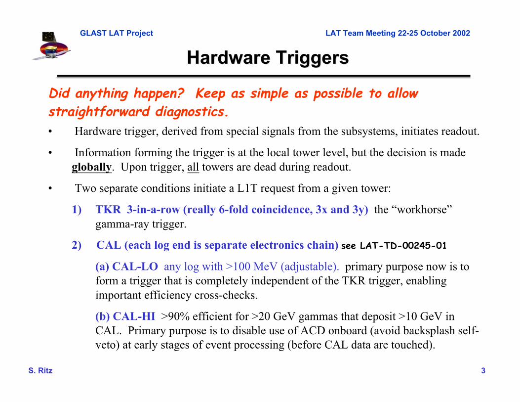
Did anything happen? Keep as simple as possible to allowstraightforward diagnostics.• Hardware trigger, derived from special signals from the subsystems, initiates readout.
• Information forming the trigger is at the local tower level, but the decision is madeglobally. Upon trigger, all towers are dead during readout.
• Two separate conditions initiate a L1T request from a given tower:
1) TKR 3-in-a-row (really 6-fold coincidence, 3x and 3y) the “workhorse”gamma-ray trigger.
2) CAL (each log end is separate electronics chain) see LAT-TD-00245-01
(a) CAL-LO any log with >100 MeV (adjustable). primary purpose now is toform a trigger that is completely independent of the TKR trigger, enablingimportant efficiency cross-checks.
(b) CAL-HI >90% efficient for >20 GeV gammas that deposit >10 GeV inCAL. Primary purpose is to disable use of ACD onboard (avoid backsplash self-veto) at early stages of event processing (before CAL data are touched).
Hardware TriggersHardware Triggers
GLAST LAT Project LAT Team Meeting 22-25 October 2002
S. Ritz 4
Importance of Optional ThrottlesImportance of Optional Throttles
• While there is no harm to the instrument to run at high rate (noconsumables, etc.), there is deadtime (20 ms per event, simplistically).Target maximum trigger rate: 10 kHz. Lower is better.
• The rate varies over the orbit. Periods of maximum trigger rate arerelatively short.
• The rates are uncertain, and have been the subject of muchdiscussion. Some flexibility for the trigger configuration is essential:need options to reduce the rate on orbit, based on what we find afterlaunch.
• If the CAL-Lo trigger runs hot, there is a simple knob to turn: thethreshold.
• There is no analog for the TKR trigger: adding more planes incoincidence is not effective. Conceptually, there are two options:– use the ACD information (see next slides)– use the CAL information (in principle possible. Hurts low-energy
effective area, but worth keeping in our back pocket, if not adesign driver. Would it really work in practice – timing complexity?Make progress on this at this meeting.)
GLAST LAT Project LAT Team Meeting 22-25 October 2002
S. Ritz 5
ACD Throttle at PDRACD Throttle at PDR
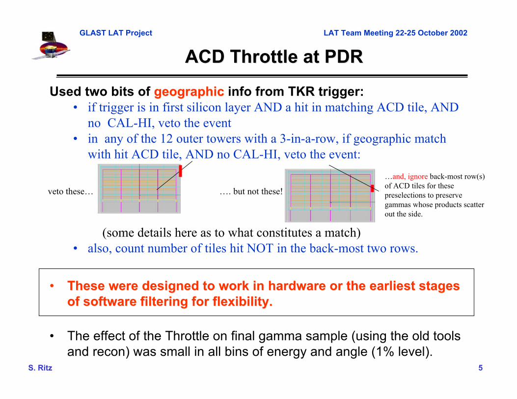
Used two bits of geographicgeographic info from TKR trigger:• if trigger is in first silicon layer AND a hit in matching ACD tile, AND
no CAL-HI, veto the event• in any of the 12 outer towers with a 3-in-a-row, if geographic match
with hit ACD tile, AND no CAL-HI, veto the event:
(some details here as to what constitutes a match)• also, count number of tiles hit NOT in the back-most two rows.
•• These were designed to work in hardware or the earliest stagesThese were designed to work in hardware or the earliest stagesof software filtering for flexibility.of software filtering for flexibility.
• The effect of the Throttle on final gamma sample (using the old toolsand recon) was small in all bins of energy and angle (1% level).
veto these… …. but not these!
…and, ignore back-most row(s)of ACD tiles for thesepreselections to preservegammas whose products scatterout the side.

GLAST LAT Project LAT Team Meeting 22-25 October 2002
S. Ritz 6
What gamma events donWhat gamma events don’’t pass throttle?t pass throttle?
because of this tile
not this one
conversionin tile

GLAST LAT Project LAT Team Meeting 22-25 October 2002
S. Ritz 7
What background sneaks through throttle?What background sneaks through throttle?
GLAST LAT Project LAT Team Meeting 22-25 October 2002
S. Ritz 8
Modification to ACD ThrottleModification to ACD Throttle
• Getting the geographic information out of the towers to theglobal trigger wasn’t as easy as initially thought: either needmore wires or implement signaling on the existing wire:judged risky.
fifi study the impact of using a non-geographic veto.study the impact of using a non-geographic veto.
Define fixed tiles “covering” each tower. The veto is then verysimple: one ACD primitive per tower. [Any othersuggestions?] It’s not pretty: if a TKR trigger occurs at theback of the stack, but an ACD tile at the top of that tower fires,the event would be vetoed. Note: corner towers have 12associated tiles.
Look at distributions of events that failed the non-geographicveto but passed the geographic veto (details, see June 2002IDT meeting).

GLAST LAT Project LAT Team Meeting 22-25 October 2002
S. Ritz 9
Fractional incremental loss of triggered areaFractional incremental loss of triggered area
cos(q)
• Losses are notterribly large, andoccur mainly far offaxis, as expected.
• After furtherselections, thefractional losses aresmaller (these arenot particularlygood gammas).
• See June 2002 IDTmeeting for details.
• Note also that the“splash veto”(counting # hit tiles)is also not veryeffective, and willlikely not be used asa throttle. 65°45°

GLAST LAT Project LAT Team Meeting 22-25 October 2002
S. Ritz 10
Implemented Orbit-max Background FluxesImplemented Orbit-max Background Fluxes
total
Integrates to ~10 kHz/m2
• LAT-TD-00250-01 Mizuno et al• Note by Allan Tylka 12 May 2000, and presentations by Eric Grove• AMS Alcaraz et al, Phys Lett B484(2000)p10 and Phys LettB472(2000)p215• Comparison with EGRET A-Dome rates provides a conservative ceilingon the total rate.
orbit-max fluxesused for triggerrate calculations

GLAST LAT Project LAT Team Meeting 22-25 October 2002
S. Ritz 11
EGRET A-dome Rates EGRET A-dome Rates (from D. (from D. BertschBertsch, EGRET team), EGRET team)
A-dome has anarea of ~6 m2,so orbit maxrate (outsideSAA and nosolar flares)corresponds to~16 kHz/m~16 kHz/m22
ThisThisrepresents arepresents aconservativeconservativeupper-limitupper-limitfor us, sincefor us, sincethe A-domethe A-domewas sensitivewas sensitivedown to 10down to 10’’ssof of keVkeV..
Note peakrate is at(24.7,260)
SAA

GLAST LAT Project LAT Team Meeting 22-25 October 2002
S. Ritz 12
Implemented Orbit-average FluxesImplemented Orbit-average Fluxes
Integrates to ~4.2 kHz/m2
orbit-avg fluxes usedfor downlink andfinal backgroundrejection calculations

GLAST LAT Project LAT Team Meeting 22-25 October 2002
S. Ritz 13
Instrument Triggering and Onboard Data FlowInstrument Triggering and Onboard Data Flow
Hardware trigger based on special signalsfrom each tower; initiates readout
Function: • “did anything happen?” • keep as simple as possible
• TKR 3 x•y pairplanes in a row workhorse workhorse gg triggertriggerx
xx
Instrument Total L1T Rate: <4 kHz>**
• subset of full backgroundrejection analysis, with loosecuts
• only use quantities thatÿare simple and robustÿdo not requireapplication of sensorcalibration constants
full instrument information available to processors.Function: reduce data to fit within downlinkHierarchical filter process: first make the simple selectionsthat require little CPU and data unpacking.
Total L3T Rate: <25-30 Hz>
• complete event information
• signal/bkgd tunable, depending on analysis cuts: g:cosmic-rays ~ 1:~few
Spacecraft
OR
(average event size: ~8-10 kbits)
**4 kHz orbit average without throttle (1.3 kHz**4 kHz orbit average without throttle (1.3 kHzwith throttle); peak L1T rate is approximatelywith throttle); peak L1T rate is approximately12 kHz without throttle and 3.8 kHz with throttle).12 kHz without throttle and 3.8 kHz with throttle).
Upon a L1T, all towers are read out within 20ms
Level 1 Trigger
• CAL: LO – independentcheck on TKR trigger. HI – indicates highenergy eventdisengage use of ACD.
On-board Processing
On-board science analysis:On-board science analysis: transient detection (AGN
flares, bursts)

GLAST LAT Project LAT Team Meeting 22-25 October 2002
S. Ritz 14
On-board Filters SummaryOn-board Filters Summary
• select quantities that are simple to calculate and that do not requireindividual sensor calibration constants. Filter scheme is flexible –current set suggestive for for flight development. See JJ’s talk.
• order of selections to be optimized. Grouped by category forpresentation purposes. Usual optimization procedure (gammas,background effects iteration).
– ACD info: match track to hit tile, count # hit tiles at low energy
Background 100 100 MeV MeV gg
outsidetileboundary
no tile hit
insidetile
boundary
Rate afterACDselectionsis ~180 Hzorbit-avg(~360 Hzorbit-max)[cm] [cm]

GLAST LAT Project LAT Team Meeting 22-25 October 2002
S. Ritz 15
On-board Filters Summary (II)On-board Filters Summary (II)
– CAL info: most of the residual rate at this point is due toalbedo events and other upward-going energy events.Require track-CAL energy centroid loose match, fractionalenergy deposit in front layer reasonably consistent withdownward EM energy flow. If no CAL energy, require trackpattern inconsistent with single-prong.
– TKR info: low-energy particles up the ACD-TKR gap easilydealt with:
project track to CAL face and
require XY position outside this
band; for low CAL energy,
require TKR hit pattern
inconsistent with single prong.
X (cm)
Y(c
m)
Rate after CAL selections is ~80Hz orbit-avg (130 Hz orbit-max)

GLAST LAT Project LAT Team Meeting 22-25 October 2002
S. Ritz 16
On-board Filter Concept ResultsOn-board Filter Concept Results
• After all selections, orbit-average background rate is 17 Hz.
chime albedo albedo CRe albedo p g e+e-
5 Hz line
2 Hz line
1 Hz line
composition:
Additional margin available: much of the residual rate is due to high-energy proton andelectron events with CAL E>5GeV -- if apply ACD selections onboard to higher energy,rate can be cut in half (to 8 Hz), with ~5% reduction in Aeff at 10 GeV.
16.5 Hz total rate

GLAST LAT Project LAT Team Meeting 22-25 October 2002
S. Ritz 17
Development ApproachDevelopment Approach
• Basic approach:
• However, until a few months ago, the main issue was data systemarchitecture and CPU requirements. In that context, the 2nd step wasjudged not to be particularly useful (or would be essentiallyindistinguishable from the 3rd) and it was largely skipped. Step (3)required reformatting simulated events to dataflow format, whichrequired that to be defined.
(1) proof of principle with full simulation tools
(2) prototype algorithms with more realism
(3) write flight software
(4) integrate flight software algorithms into full simulationto study and iterate

GLAST LAT Project LAT Team Meeting 22-25 October 2002
S. Ritz 18
Development StatusDevelopment Status
• Basic approach:
• (1) was done prior to PDR. (3) lots of progress after logjam brokenpost-PDR (see JJ’s talk next). (4) must now be done – interacts withour SAS development plans and schedule: see next slide.
(1) proof of principle with full simulation tools
(2) prototype algorithms with more realism
(3) write flight software
(4) integrate flight software algorithms into full simulationto study and iterate

GLAST LAT Project LAT Team Meeting 22-25 October 2002
S. Ritz 19
ToolsTools
• PDR studies and JJ’s filter studies were done using pdrApp(the GISMO-based simulation and reconstruction package lineused since the start of the project). Development has nowhalted on pdrApp.
• GLEAM, which is the new Geant4-based package line, is beingdebugged and brought up to speed. The architecture issufficiently different that recon and other analysis tools frompdrApp can not be plugged in. (But the new recon is muchbetter!)
• The last essential step for validation of the flight algorithmsrequires:– updating JJ’s event reformatting algorithm to be adapted
for GLEAM– packaging JJ’s algorithms for use in GLEAM. The FSW
objects (tracks, selection quantities) must be available inthe standard recon output
•• At this meetingAt this meeting: work out who (not just FSW group) and how(details) and when (soon).

GLAST LAT Project LAT Team Meeting 22-25 October 2002
S. Ritz 20
To DoTo Do
• Improve angular distributions of the background fluximplementations. Volunteer!Volunteer!
• Finish first flight software filter implementation. This requiresThis requiresa clear statement of priority.a clear statement of priority.
• Include the flight algorithms in reconstruction/analysispackages to study the effects in detail. Migrate JJ’s formatterto GLEAM. PLAN AT THIS MEETINGPLAN AT THIS MEETING. Check everything.