
GLASSFIBERBOLT (GFRP) SOM PERMANENT SIKRINGSBOLT
12
6-1 FJELLSPRENGNINGSTEKNIKK BERGMEKANIKK/GEOTEKNIKK 2018 GLASSFIBERBOLT (GFRP) SOM PERMANENT SIKRINGSBOLT Glass fibre reinforced plastic (GFRP) permanent rockbolts AlunThomas, Tunnel Director, Minova SAMMENDRAG Glass Fiber Reinforced Plastic ( GFRP) har blitt brukt i en årrekke i forskjellige elementer av tunneler, blant annet som sikringsbolt. Primært som midlertidig bolt, da den er gunstig når det skal bores videre på et sikret område, samt ikke like skadelig hvis massene skal til knusing. Glassfiber har flere andre fortrinn, som lav vekt, dette reduserer belastningen ved manuell håndtering. Den er også gunstig miljømessig. GFRP har også en god varighet/levetid, og har blitt brukt som permanent sikring under krevende forhold, som undersjøiske fjellhaller for oljelagring. Ett hinder for en mer utstrakt bruk av GFRP som permanent sikringsbolt, har vært en bekymring med tanke på skjær. Dette innlegger vil presentere data fra en fullskala skjærtest av sikringsbolter, og legge frem en ny design metode som vil redgjøre for fordelene ved at boltene motstår skjærkreftene i ustabile bergmasser. Det er anerkjent at under skjærkreftenes påvirkning, så deformes boltene ved bøying, og boltenes strekkfasthet styrer denne oppførselen. Denne nye metoden er for anvendelig for både stål og GFRP bolter. Et beregningseksempel med en numerisk modell vil presenteres, dette for å vise hvordan GFRP bolter kan erstatte stålbolter, dette i et klassisk nordisk tunneldesign, hvor boltene må motstå både strekk og skjærbelastning fra bergmassene. Dette vil muliggjøre en mer utstrakt bruk av GFRP bolter, en bolt som er overlegen med tanke på levetid, samt har en mindre miljøbelastning.
Transcript of GLASSFIBERBOLT (GFRP) SOM PERMANENT SIKRINGSBOLT

6-1
FJELLSPRENGNINGSTEKNIKK BERGMEKANIKK/GEOTEKNIKK 2018
GLASSFIBERBOLT (GFRP) SOM PERMANENT SIKRINGSBOLT Glass fibre reinforced plastic (GFRP) permanent rockbolts
AlunThomas, Tunnel Director, Minova
SAMMENDRAG
Glass Fiber Reinforced Plastic ( GFRP) har blitt brukt i en årrekke i forskjellige elementer av tunneler, blant annet som sikringsbolt. Primært som midlertidig bolt, da den er gunstig når det skal bores videre på et sikret område, samt ikke like skadelig hvis massene skal til knusing. Glassfiber har flere andre fortrinn, som lav vekt, dette reduserer belastningen ved manuell håndtering. Den er også gunstig miljømessig. GFRP har også en god varighet/levetid, og har blitt brukt som permanent sikring under krevende forhold, som undersjøiske fjellhaller for oljelagring. Ett hinder for en mer utstrakt bruk av GFRP som permanent sikringsbolt, har vært en bekymring med tanke på skjær. Dette innlegger vil presentere data fra en fullskala skjærtest av sikringsbolter, og legge frem en ny design metode som vil redgjøre for fordelene ved at boltene motstår skjærkreftene i ustabile bergmasser. Det er anerkjent at under skjærkreftenes påvirkning, så deformes boltene ved bøying, og boltenes strekkfasthet styrer denne oppførselen. Denne nye metoden er for anvendelig for både stål og GFRP bolter. Et beregningseksempel med en numerisk modell vil presenteres, dette for å vise hvordan GFRP bolter kan erstatte stålbolter, dette i et klassisk nordisk tunneldesign, hvor boltene må motstå både strekk og skjærbelastning fra bergmassene. Dette vil muliggjøre en mer utstrakt bruk av GFRP bolter, en bolt som er overlegen med tanke på levetid, samt har en mindre miljøbelastning.

6-2
INTRODUCTION
GFRP has been used in many applications in civil engineering and other fields for decades. However, it is used less often in tunnelling. At the same time this material offers many ad-vantages. In terms of its structural performance, it is particularly suitable for linear reinforcing elements such as bars in concrete or rock bolts. In the following sections, this paper will elab-orate on the properties of the material as well as its advantages. Design issues, notably shear, are discussed. The performance of GFRP rockbolts has been demonstrated on projects world-wide. GFRP – sometimes known as fibreglass – consists of glass fibres, either as long strands, mats or chopped fibres, encased in a resin. It was first developed in 1936 in USA and the first known structural use was the hull of a boat in 1937. Having gained popularity in the 1950s, GFRP is often see in applications which draw on its high strength, light weight and flexibility. Common examples include storage tanks, boats, building cladding panels and pipes but it is also used in high performance applications such as wind turbine blades, aircraft fuselages and pole-vaulting poles. Many different forms of GFRP exist and, depending on its components and manufacture, GFRP can be considerably stronger than steel and cheaper and more flexible than carbon fibre. As one might expect with a composite material, there can also be a considerable variation in quality, depending on the supplier. For the best quality, GFRP should be produced in a pultru-sion process in a temperature controlled environment, using high quality glass fibres, having a high fibre content of about 75%. Hence the product is of high quality. The glass fibres are embedded in either Polyester- or Vinylester- or Epoxy resin matrix. This gives the rod a high tensile strength, especially in the longitudinal direction. The resin matrix fixes and protects the glass fibres. The most durable GFRP uses a Vinylester resin matrix. The fib report (fib 2005) provides an excellent overview of GFRP in general. MECHANICAL BEHAVIOUR
Table 1 outlines the main properties of a GFRP rockbolt, alongside those of a standard 20 mm diameter steel bolt. The latter is a bolt size commonly used in tunnelling and it is the basis for rock support in the Q-system chart. As noted above, by the nature of the manufacturing process
SUMMARY
Glass Fibre Reinforced Plastic (GFRP) has been used for many years in tunnelling appli-cations, including rockbolting. This has been primarily for temporary applications due to the ease of cutting GFRP. GFRP has many other advantages such as its light weight which reduces manual handling impacts on workers in the tunnel and its lower environmental impact. GFRP also has excellent durability characteristics and permanent GFRP rock bolts have been used successfully in demanding situations such as subsea oil storage cav-erns.
One obstacle to the more widespread adoption of GFRP for permanent applications has
been a concern over its performance in shear. The paper will present data from full scale shear tests on rockbolts and describe a new design method to account for the benefit of the bolts in resisting shearing on discontinuity planes. It is well understood that during shearing the rockbolts actually deform under bending and the tensile strength of the bolt governs the behaviour. This new method is valid for both steel and GFRP bolts. An ex-ample calculation with a numerical model is presented to illustrate how this design method can be used to demonstrate that GFRP bolts function as well as steel bolts in a typical Nordic tunnel design situation in terms of resisting both tensile and shear loading from the rock mass. This opens the path for the wider use of GFRP rockbolts which offer superior durability and a lower environmental impact.

6-3
GFRP bolts or reinforcing bars are orthotropic and they have a higher strength in the longitu-dinal direction than in the transverse direction. In contrast steel is isotropic. This becomes rel-evant when the angle of loading is relevant – for example, in shear. In shear tests at 90°, GFRP typically has a strength which is 10% lower than steel. However, in rock applications, shearing occurs at lower angles where GFRP is stronger. Hence, the average values from tests at 50° have been stated in the table below – see also section 0.
Table 1: Key mechanical properties of GFRP (FIREP K60-25) and steel bolts
Parameter GFRP Steel Notes
K60-25 M20
Internal diameter of solid bar / mm
21 20
External diameter / mm 24 Including the thread
Cross sectional area of core / mm2
350 299 For structural purposes
Tensile strength / MN/m2 1000 600 Characteristic value
Material partial factor of safety, �m
1.9* 1.15 * GFRP as per fib (2005) section 3.5 for wet conditions & 100 year service life
Design tensile strength / MN/m2
525 522 GFRP as per fib (200)
Elastic modulus / MN/m2 50,000 200,000 Steel modulus assumed
Working load (Yield strength) / kN
183 137 Safe working load
Elongation / % 2 8 In a tensile test
Shear strength at 50° 347** 204 ** Average value. The winding of glass fibres to form a thread on FIREP’s K60-25 bolt enhances greatly its shear capac-
ity
Maximum load / kN
Density / kg/m3 2200 7800
Other advantages of GFRP include:
• Very durable (see section 0)
• Non-magnetic (no stray current corrosion)
• Easy to cut
• No electrical conductivity
• High thermal insulation
• Flexible (the elastic modulus is a quarter of steel) Various coatings can be added to GFRP such as an anti-static coating or UV protection (for outdoor applications to protect the components from the harmful effects of ultraviolet radia-tion). DESIGN
Several organizations and countries have published design standards for the use of GFRP, gen-erally in the context of reinforcement for concrete – fib (2005), CNR (2006) and ACI 440.1R-

6-4
03 (2003). In Table 1, the partial factor of safety for the material has been derived according to the fib code (fib 2005), based on Minova FIREP bolts and a 120 year design life.
Tensile behaviour
While GFRP is almost twice as strong as steel in the longitudinal direction, which is the primary load bearing direction for bolts and bars, when the relevant safety factors are applied, the ca-pacity as a working load for the bolts is basically the same for a GFRP and steel bolt of the same diameter. In other words, GFRP can replace steel in a rock support design without any significant changes to the design or construction.
In some locations, GFRP bolts are already being used as permanent rock support, e.g. Sydney, Australia. Salcher & Bertuzzi (2018) summarized the results of pull-out tests for permanent rockbolts on the Metro North West project in Sydney, concluding that GFRP bolts performed just as well as steel bolts in terms of pull-out stiffness and grout-bar bond strength.
Figure 1: Typical pull-out test results for GFRP and steel bolts
Shear behaviour
While rock bolts are designed to act primarily in tension, they can be loaded in shear too. This design case is rarely checked in typical rock tunnel design and in fact most numerical modelling software simulates rock bolts as tensile 1D elements – i.e. they cannot carry any shear load. Due to the high horizontal insitu stresses in the Hawkesbury sandstone, Sydney, Australia, is one of the very few places in the world where rockbolts are designed to carry shear. Conse-quently a number of authors have proposed design methods for this case. There is a consensus, supported by experimental evidence, that the mode of failure in this shear case is in fact local

6-5
bending of the bolt, causing crushing of the grout and rock adjacent to the shearing plane and an extension of the bolt until it fails in tension – as shown in Figure 1.
Figure 2: Conceptual model of bolt bending during shearing (Badelow et al. 2005)
Pells proposed a comprehensive analytical solution for this mode of failure in 2002. How-
ever, the original article is believed to have numerous typographical errors in the equations and Pells himself has questioned the theory’s ability to match test results (Pells et al 2018). Fur-thermore, in the author’s experience, the solution does not match the real test data well. The conceptual model above comprises a frictional enhancement and a resistance provided by the bolt in tension. The relative contributions vary with shear displacement and the angle of inci-dence.
Badelow et al (2005) set out a design method for determining the contribution of bolts to shear strength at joints, accounting for the bending and extension of the bolts. In the original paper, the radius of curvature of the bolt, R, is assumed to be constant. One might expect that in fact R is initially very large and then reduces as there is displacement along the joint and yielding of the grout permits more localized bending. There is also an assumption – which is largely valid for steel – that the bolts have yielded, unless the deflections are very small. Hence the enhancement of shear force on the joint is expressed as a multiple of the yield force in the bolt. This is not necessarily true for GFRP. The enhancement can be expressed more generally as:
SF = (F+Fp).(sin α.tan φj + cos α) (1)
where SF = total shear resistance, F = the force in the bolt due to extension, Fp = the preten-
sion force in the bolt, α = angle of the bolt to the plane of shearing and φj = joint friction angle In an improvement to the method by Badelow et al. (2005), a new expression is proposed to
determine the slope of the bolt, based on the theory of bending of piles under horizontal loads. This have been calibrated against full-scale shear tests on both steel and GFRP bolts at different angles to the plane of shearing. Considering one half of the bolt (i.e. P/2) – see Figure 3, the slope at the joint provides the angle, α, a key input for the estimation of the shear enhancement, can be found from:
tan�� − �� =�2
2����
(2)

6-6
where P is the total shearing force acting on the block, E is the stiffness of the bolt, I is the second moment of inertia of the bolt and β defined by
� = √4����
(3)
where k is the lateral coefficient of reaction, which can be obtained from back-analyzing full scale shear tests on bolts.
Figure 3: Conceptual model of a bolt in rock under shearing
Having determined the shear force that the bolt is capable to resisting, SF, this can be added
as an increased joint cohesion in the analytical or numerical model of a tunnel, thereby enabling the shear case to be checked. So long as the model shows that the joint does not yield and the joint displacement is less than the value corresponding to the assumed shear capacity, it can be concluded that the bolts will carry the shear loads from the rock.
Figure 4 shows the predicted values of the normalized shear force which can be carried by a fully grouted Minova Firep K60-25 bolt with a joint friction angle of 20° and zero pretension. The bolt ultimate tensile capacity, FY, is 350 kN. These predictions from this new method agree well with data from 25 full scale shear tests for GFRP and steel.

6-7
Figure 4: Normalized shear force enhancement vs displacement curves for various angles
of incidence, i = 50° & 90° (FY =350 kN).
Figure 5 shows the results from some full scale shear tests and the prediction using this
method.
Figure 5: Full scale shear test data (at 90°) & prediction
6-8
This method offers a simple way to demonstrate that the GFRP bolts can carry the expected shear loads. A more thorough description of this new design method is planned in a forthcom-ing paper.
Considering the context of hard rock tunnelling in Scandinavia, it is rare to encounter con-ditions where high shear stresses would be expected. In general the insitu stress state is quite stable with block movements dominating. Considering the sliding of a block, one could imag-ine that a single rock bolt might have to resist a shear load of about 30 to 50 kN, if one ignores the shear resistance on the joints. Figure 5 shows that, even in this extreme case, a GFRP bolt has a shear capacity that is 2.5 to 4 times higher than the load.
DURABILITY
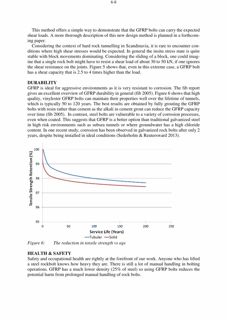
GFRP is ideal for aggressive environments as it is very resistant to corrosion. The fib report gives an excellent overview of GFRP durability in general (fib 2005). Figure 6 shows that high quality, vinylester GFRP bolts can maintain their properties well over the lifetime of tunnels, which is typically 50 to 120 years. The best results are obtained by fully grouting the GFRP bolts with resin rather than cement as the alkali in cement grout can reduce the GFRP capacity over time (fib 2005). In contrast, steel bolts are vulnerable to a variety of corrosion processes, even when coated. This suggests that GFRP is a better option than traditional galvanized steel in high risk environments such as subsea tunnels or where groundwater has a high chloride content. In one recent study, corrosion has been observed in galvanized rock bolts after only 2 years, despite being installed in ideal conditions (Sederholm & Reutersward 2013).
Figure 6: The reduction in tensile strength vs age
HEALTH & SAFETY
Safety and occupational health are rightly at the forefront of our work. Anyone who has lifted a steel rockbolt knows how heavy they are. There is still a lot of manual handling in bolting operations. GFRP has a much lower density (25% of steel) so using GFRP bolts reduces the potential harm from prolonged manual handling of rock bolts.

6-9
ENVIRONMENTAL IMPACT
As we become more aware of our negative impact on the environment, there is a growing need to reduce this impact. One of the ways to do this is to use products which have inherently less impact on the environment, such as GFRP. Kodymova et al. (2017) described a Life Cycle Assessment of GFRP and steel permanent rockbolts and concluded that GFRP bolts could have up to 40% less environmental impact than an equivalent twin coated steel bolt. These are the 2 main options for permanent rock bolts. In part this benefit arises from the lower weight of the GFRP bolts which weigh a quarter of the equivalent steel bolts. However, GFRP was better in all ten categories examined (see Figure 7) and not just in terms of embodied carbon (see Global Warming Potential category in the original paper).
Figure 7: The characterization of a rock bolt - shipped from China and Europe (midpoint
category, CML method) – Kodymova et al 2017
As an aside, another good way to reduce the impact of construction is to source materials lo-cally. The concept of “food miles” was first coined by Prof Tim Lang in the 1990s and it is now well-established in the public consciousness in terms of food shopping and our environ-mental impact. Of course, this only one element of the overall environmental impact but the attention on it as a major influence has helped to push positive trends towards more sustainable food production. Similarly, in the construction industry, we may need to start thinking about “materials miles” as an important aspect in enhancing the sustainability of our projects. The study above considered the use of the permanent bolts in a tunnel in Scandinavia with bolts sourced in Europe or from China. The negative impact of transporting products halfway around the world is clearly visible – see ratings for Global Warming Potential in Figure 7.
CASE STUDY – THE VEREINA TUNNEL
An excellent example of the use of permanent GFRP rockbolts in a demanding environment is the Vereina tunnel. Vereina is a narrow-gauge railway tunnel in eastern Switzerland. For the most part, it has a single track, while there are three double track areas where trains can pass. Vereina is an essential part of the railway network in the Canton of Graubünden and, at 19.1 km long, it is the longest narrow gauge railway tunnel in Switzerland. With an overburden ranging up to 1500 m and a highly heterogeneous geology, many challenges for the tunnel excavation had to be overcome. Dramatic rock burst as well as extensive water inflow and squeezing were encountered – see Figure 8. The construction began in 1991 and tunnel was opened in November 1999.

6-10
The Vereina tunnel is well-known within the tunnelling fraternity as one of the largest uses
of permanent sprayed concrete as a single shell tunnel lining in Switzerland. What is less well known is that it also featured GFRP bolts as the permanent rock support. The vinylester GFRP rock bolts from Minova via FIREP were chosen because of their excellent resistance to corro-sion and high durability. The bolts were anchored using Minova’s Lokset, fast-acting resin cartridges. In the very end of the bore hole, fast reactive resin cartridges were used, while fur-ther back a slower reactive resin was applied. After 10 minutes, the fast reacting resin had hardened and the bolt was manually prestressed to increase the effectiveness of the rock bolts at the face. Additional sprayed concrete and hollow GFRP rock bolts were added later to be able to cope with the requirements for the permanent support and guarantee long term stability. Altogether almost 100,000 GFRP rock bolts were installed. Over the course of the last 20 years, the rock support has been inspected regularly and the GFRP bolts are performing very well – see
Figure 9.
Figure 8: Squeezing ground supported by GFRP bolts and sprayed concrete

6-11
Figure 9: The Vereina tunnel in operation
CONCLUSIONS
GFRP rockbolts are a proven technology for permanent rock support, with excellent durability over a design life of more than 100 years. GFRP has also a significantly lower environmental impact than the normal steel options. A new analytical method has been developed to describe the behaviour rock bolts in shear, based on the concept by Badelow et al. (2005). This matches experimental data well. This method permits the shear enhancement provided by either steel or GFRP bolts to be incorporated in the joint properties of a standard numerical model for the design of a tunnel so that the capacity of the bolts in shear can be checked. As discussed, broadly speaking, steel bolts can be exchanged for GFRP bolts of the same diameter in rock support design. With the trend to use permanent rockbolts and an increasing emphasis on reducing our environmental impact, GFRP rock bolts offer an excellent solution. ACKNOWLEDGEMENTS
The author would like to acknowledge his colleagues in Minova, in particular Terje Seterdal, and FIREP for their support in the background studies for this paper. REFERENCES
ACI 440.1R-03 (2003) “Guide for the Design and Construction of Concrete Reinforced with
FRP Bars”, ACI - American Concrete Institute, Farmington Hills, MI, USA.
Badelow, F., Best, R., Bertuzzi, R. & Maconochie, D. (2005). Modelling of defect and rock bolt
behaviour in geotechnical numerical analysis for Lane Cove Tunnel”, AGS AUCTA Mini-Sym-
posium: Geotechnical Aspects of Tunnelling for Infrastructure Projects – October 2005
CNR (2006) Guide for the design and construction of concrete structures reinforced with fiber-
reinforced polymer bar”, CNR-DT 203/2006, Italian National Research Council, Rome, Italy.

6-12
fib (2005), FRP Reinforcement for reinforced concrete Structures”, Task Group 9.3 (Fiber
Reinforced Polymer) Reinforcement for Concrete Structures, INTERNATIONAL FEDERA-
TION FOR STRUCTURAL CONCRETE. Lausanne, Switzerland.
Kodymova, J., Thomas A.H. & Will, M. (2017). Life-cycle assessments of rock bolts”, TUN-
NELLING JOURNAL, June/July, p 47-49.
Pells, P.J., Pells, S.E. & Pan, L. (2018). On the resistance provided by grouted rock reinforce-
ment to shear along bedding planes and joints”, AUSTRALIAN GEOMECHANICS Vol 53 No.
2 June 2018
Salcher, M. & Bertuzzi, R. (2018). Results of pull tests of rock bolts and cable bolts in Sydney
sandstone and shale”, TUST - Tunnelling and Underground Space Technology 74 (2018): 60–
70.
Sederholm, B. & Reutersward, P. (2013) Corrosion testing of different types of rock bolt”,
BEFO Report 127, Rock Engineering Research Foundation, Stockholm.


![GFRP [Hand lay up]](https://static.fdocuments.net/doc/165x107/557cb1dcd8b42abf328b4c0e/gfrp-hand-lay-up.jpg)


