
GL-9 MANUAL 9,000 POUND TWO POST GOLF...
25
1 GL-9 MANUAL 9,000 POUND TWO POST GOLF LIFT 2003C GOLF LIFT P.O. BOX 150941 FORT WORTH TX 76108-0941 PHONE (800) 788-9789
Transcript of GL-9 MANUAL 9,000 POUND TWO POST GOLF...

1
GL-9
MANUAL
9,000 POUND
TWO POST GOLF LIFT 2003C
GOLF LIFT P.O. BOX 150941
FORT WORTH TX 76108-0941 PHONE (800) 788-9789

2
This lift is a 9000 lb. capacity, 2-Post Lift. The safety latch system is very similar to an extension ladder. The safety latch is in contact with the rack as the lift ascends and drops into place as the lift rises. Safety latch engages in rack in 3” increments at about 16” from the ground. The latch must be manually disengaged for the lift to descend. The latch is released by pulling the release cable raising the latch up off the latch rack. Once the raise button is pressed, the latch will automatically re-engage after approximately 3" of travel. Heavy bearings and heavy-duty leaf chains are used throughout the lift. The work is done with the heavy-duty chain connected to a 2-1/2" cylinder, driven by a hydraulic pump capable of providing 3,000 psi. Please read the Safety Procedures and operation instructions in this manual before operating the lift. Proper installation is very important. To minimize the chance of making an error in installation, please read this manual through carefully before beginning installation. Check with building owner and /or architect’s building plans when applicable. The lift should be located on a relatively level floor with 4” 3000 psi concrete sufficiently cured. Place the ramp pan side away from door. Turf equipment should be backed on – placing the rear wheels on the ramp pan and centered between posts. When approaching lift the forks should be rotated away to give maximum clearance. When loading large fairway mowers the outside half of the wheel fork slider may be removed. (Vehicles with extra wide tread widths can be loaded without removing the slider if equipped with the lob-wedge adapter set part # GL-LW.) When replacing the slider – be sure the wheel forks are tight against the tire and the pins are locked in the slider. If you wish to lift a truck or passenger car- remove the ramp and replace short arm and wheel forks with long arms and swivel pads and / or truck adapters. You may order a set for your lift. Order # GL-TA (GL-TA comes standard beginning with year 2003 model).
Warning: Do not lift flat or under inflated tire with wheel fork adapters.
Always lock the lift before going under the vehicle. Never allow anyone to go under the lift when raising or lowering. Read the safety procedures in the manual.
This is a vehicle lift installation / operation manual and no attempt is made or implied herein to instruct the user in lifting methods particular to an individual application. Rather, the contents of this manual are intended as a basis for operation and maintenance of the unit as it stands alone or as it is intended and anticipated to be used in conjunction with other equipment. Proper application of the equipment described herein is limited to the parameters detailed in the specifications and the uses set forth in the descriptive passages. Any other proposed application of this equipment should be documented and submitted in writing to the factory for examination. The user assumes full responsibility for any equipment damage, personal injury, or alteration of the equipment described in this manual or any subsequent damages.

3
IMPORTANT CONCRETE AND ANCHORING INFORMATION 1. Concrete shall have compression strength of at least 3,000 PSI and a minimum thickness of 4” in order to achieve a minimum anchor embedment of 3 ¼”. When using the standard supplied ¾” x 5 ½” long anchors, if the top of the anchor exceeds 2 ¼” above the floor grade, you DO NOT have enough embedment. 2. Before drilling ¾” dia. holes in concrete floor using holes in column base plate as a guide. Make sure the hole distance from the edge is not less than 6”. Hole to hole spacing should not be less than 6 ½” in any direction. Concrete thickness or hole depth should be a minimum of 4 ¼”. 3. CAUTION. DO NOT install on asphalt or other similar unstable surface. Columns are supported only by anchoring in floor. 4. Using the horseshoe shims provided, shim each column base until each column is plumb. If one column has to be elevated to match the plane of the other column, full size base shim plates should be used (Reference Shim Kit). Torque anchors to 150 ft-lbs. Shim thickness MUST NOT exceed ½” when using the 5 ½” long anchors provided with the lift. Adjust the column extensions plumb. 5. If anchors do not tighten to 150 ft-lbs. Installation torque, replace concrete under each column base with a 4’ x 4’ x 6” thick 3,000 PSI minimum concrete pad keyed under and flush with the top of existing floor. Let concrete cure before installing lifts and anchors. PREPARATION The installation of this lift is relatively simple and can be accomplished by 2 men in a few hours. The following tools and equipment are needed: Appropriate lifting equipment
AW 32, 46 or other good grade Non-Detergent Hydraulic Oil SAE-10 (12 quarts) Chalkline and 12' Tape Measure Rotary Hammer Drill with 3/8” and 3/4" Drill Bit. Core Drill ReBar Cutter recommended Transit and a 4' Level Sockets and Open Wrench set, 1/2" thru 1-1/2" (1-1/8" for 3/4" Anchors) Vise Grips, 8mm Allen wrench

4
GENERAL INFORMATION 1. Any freight damage must be noted on the freight bill before signing and
reported to the freight carrier with a freight claim established. Identify the components and check for shortages. If shortages are discovered, contact us immediately.
2. Lift location- check with building owner and /or architect’s building plans when applicable. The lift should be located on a relatively level floor with 4” 3000 psi concrete sufficiently cured with no cracks within 36” and no seams with in 6”of the base plate. Remember any structure is only as strong as the foundation on which it is located.
3. Check for ceiling clearance - lifting height (72”) plus vehicle height. Check for clearance in the front and rear of vehicle when on lift - with the garage door closed. Positioning columns can be best determined by parking your largest vehicle (long truck) in the bay where the lift is to be located. Leave the desired work area around the vehicle and create centerline of columns from near the vehicles front door jam or steering wheel for center of load. Every other vehicle will be shorter in length and you will have plenty of space.
STEP 1: After unloading the lift, place it near the intended installation location. STEP 2: Remove the shipping bands and packing materials from the lift. The power unit, rear ramp, floor cover and cylinders will be unpacked from the top. STEP 3: Open the wrapping from the upper column and carefully remove the parts from inside. Unbolt the column from the shipping brackets. The column top plate will come loose when unbolting, use bolts from hardware kit with lock washers provided to bolt top plate back on without shipping bracket. STEP 4: Once unpacked the upper column should be stood upright (Note the power unit column can be located on either side, look for the power unit mounting bracket and locate this column on the side where the power will be ran). Repeat process for the bottom column. STEP 5: Position the columns facing each other 138” outside base plates (see fig 1.) Square the columns by measuring diagonally from exact same points on base plates (within1/4”). STEP 6: Using a 3/4" concrete drill, drill the anchor holes in the main side column, installing anchors as you go. Use a block of wood or rubber mallet to drive anchor bolts in. Drill to a minimum depth of 4" to insure maximum holding power. Drilling thru concrete (recommended) will allow the anchor to be driven thru the bottom if the threads are damaged.

5
STEP 7: Using a level, check column for side-to-side plumb and front-to-back plumb. Use horseshoe shims provided by placing shims underneath the base plate and around the anchor bolt. This will prevent bending the column bottom plates (Shim thickness should not exceed ½ “). Tighten ¾” anchor bolts to 150 ft-lbs. of torque. STEP 8: Using a tape measure, measure from back corner of the base to the opposite back corner to insure legs are square. Using the dimensions, drill and install the anchors on the off side leg. STEP 9: Level the columns as described in step #7. STEP 10: Cylinder installation – Gently lower cylinder into carriage (steel hex head plug in bottom of cylinder should face back side of column) while holding chain up and out of the way. Make sure cylinder sets into notch hole at bottom of carriage and that the cable release is out of the way. It may be necessary to manually raise the carriage up slightly to loop the chain onto the cylinder pulley. Repeat process on opposite side. STEP 11: Manually raise each carriage up onto the latches – approximately 16” - danger watch out - chain could be kinked - double check the latches before working under the carriage. Be sure each carriage is at the same height by measuring from the top of the base to the bottom of the carriage. This dimension should be within 1/4". STEP 12: Mount the power unit on the main side leg with the power unit bracket using the four 5/16 bolts and nuts. Install the 90 degree fitting with o-ring on the power unit. Next install the two 45 degree hydraulic fittings into the bottom of each cylinder using Teflon pipe sealer. Install the 6” pipe into the backside of the main column cylinder (power unit side) by first removing the 8mm steel plug. Install the 90 degree hydraulic fitting on the other end of the 6” pipe. Start at the fitting at power unit, run the hose down the column to the fitting on the base of cylinder. Run long hose across to base of opposite column and connect to the fitting. STEP 13: Connect the cables as shown in the cable diagram – Fig. 3. Do not tighten at this stage of assembly. Note – The cable stud that connects to the front right corner of the carriage should be connected first by pulling the stud through the carriage hole and up where it is easy to be held by vise grips. Then pull it back into place after tightening at least ½” of thread showing past lock nut. Connect the other ends to the rear right corners of the carriage with at least ½” of thread showing past lock nut (cables run on inside of carriage). It may be necessary to manually raise both carriages above the cylinder to provide enough space to use vise grips. Make sure the carriage is setting in the LOCK position.

6
STEP 14: Adjust the carriage cables tension. This is accomplished by tightening the rear nut on top of each carriage. The rear carriage adjustment nut adjusts for opposite post carriage height. The left post carriage nut adjusts the right column carriage, and the right column carriage nut adjusts the left column carriage. Adjust each cable to approximately 1/2" side-to-side play. Check the latch releases to insure the carriage is still sitting on the appropriate latch. STEP 15: Locate and position the cable floor cover at the center of the lift in all directions. Drill four 3/8” holes through the tabs. Mount the cable floor cover with 3/8” anchor bolts. Tighten 3/8 anchor bolts to 25 ft-lbs. of torque. STEP 16: Install the half moon gear locks on each swing arm (USA side up). Position the swing arms on the carriages using the included 1 1/2" diameter pins (2 short front arms and 2 long rear arms). Check for proper engagement of the arm lock – the rack on the lock should fully engage the gear on the arm. Install tire-wedge fork assemblies on the 2 short arms with the slider side to the outside or away from column. Install the Lob-Wedge ramps onto each Tire-Wedge adapter. STEP 17: Remove the vent plug from the power unit and fill the reservoir. Use a Ten Weight (SAE-10) non-foaming, non-detergent hydraulic fluid (Texaco HD46 or equal). The unit will hold approximately twelve quarts of fluid. STEP 18: Make the Electrical hookup to the power unit. 220V Single Phase. It is recommended that a 220 Volt, 30 Amp twist lock plug be installed in the power line just ahead of the power unit. Size wire for 30-amp circuit. Warning - the wiring must comply with local code. Have a certified electrician make the electrical hook-up to the power unit. Protect each circuit with time delay fuse or circuit breaker 208v-230v single phase. 60 Hz 30 amp. Motor can not run on 50 Hz with out a physical change to motor. STEP 19: Do not place any vehicle on the lift at this time. Cycle the lift up and down several times to insure latches click together and all air is removed from the system. To lower the lift, both latch releases must be manually released. Latches will automatically reset once the lift ascends approximately 17”. If latches click out of sync, tighten the cable on the one that clicks first. Install the rear ramp pan over the 2 long arms (Notched stirrup side should face the columns). Screw T-handles on each side of ramp.

7
RAISE – LIFT I. Press button on power unit Lock - The latch mechanism will 'trip over' when the lift raises and drop into each latch stop. But, to lock the lift you must press the Lower lever to relieve the hydraulic pressure and let the latch set tight in a lock position. Note: It is normal for an empty lift to lower slowly - it may be necessary to add weight. LOWER LIFT 1. Raise the lift until the latch clears. 2. Pull both latch releases Warning Always Release Both Sides 3. Press the lever at the power unit to lower the lift. ALWAYS LOCK THE LIFT BEFORE GOING UNDER THE VEHICLE. NEVER ALLOW ANYONE TO GO UNDER THE LIFT WHEN RAISING OR LOWERING.

8
SAFETY PROCEDURES • Never allow unauthorized persons to operate lift. Thoroughly train new
employees in the use and care of lift. • Caution - the power unit operates at high pressure. • Remove passengers before raising vehicle. • Prohibit unauthorized persons from being in shop area while lift is in
use. • Total lift capacity is 9000-lbs. with 2250-lbs. per tire-wedge fork and
4500-lbs. total on rear ramp plate. The GL-TA truck option has a total 9000-lbs. capacity with 2250 per swivel pad. Do not exceed. Note models GL-9 and GL-7 sold before 11-99 has a 7000-lb. total capacity for turf arm system. 1750-lbs. for each tire-wedge fork and 3500-lbs. for rear ramp.
• Prior to lifting vehicle, walk around the lift and check for any objects
that might interfere with the operation of lift and safety latches; tools, air hoses, shop equipment.
• When approaching the lift with a vehicle, center the vehicle between the
columns so that the tires will clear the swing arms easily. Slowly drive the vehicle up between the posts. Have some one outside the vehicle guide the driver.
• Always lift vehicle using both tire-wedge forks and ramp plate or all four
pads when using GL-TA truck option. • Never use lift to raise one end or one side of vehicle. • Never lift flat or under inflated tire with tire-wedge fork adapters. • Raise vehicles about 3’ and check stability by rocking. • Prior to lowering vehicle, walk around the lift and check for any objects
that might interfere with the operation of lift and safety latches; tools, air hoses, shop equipment. Swing the arms and tire-wedge forks out and slowly drive the vehicle out. Have some one outside the vehicle guide the driver.

9
MAINTENANCE SCHEDULE The following periodic maintenance is the suggested minimum requirements and minimum intervals; accumulated hours or monthly period, which ever comes sooner. If you hear a noise or see any indication of impending failure - cease operation immediately - inspect, correct and/or replace parts as required. WARNING OSHA AND ANSI REQUIRE USERS TO INSPECT LIFTING EQUIPMENT AT THE START OF EVERY SHIFT. THESE AND OTHER PERIODIC INSPECTIONS ARE THE RESPONSIBILITY OF THE USER. DAILY PRE-OPERATION CHECK (8 HOURS) The user should perform daily check. ATTENTION! LOOK OUT! Daily check of safety latch system is very important - the discovery of device failure before needed could save you from expensive property damage, lost production time, serious personal injury and even death. • Check safety lock audibly and visually while in operation • Check safety latches for free movement and full engagement with rack. • Check hydraulic connections, and hoses for leakage. • Check chain connections - bends, cracks-and looseness. • Check cables connections- bends, cracks-and looseness. • Check for frayed cables in both raised and lowered position. • Check snap rings at all rollers and sheaves. • Check bolts, nuts, and screws and tighten. • Check wiring & switches for damage. • Keep base plate free of dirt, grease or any other corrosive substances. • Check floor for stress cracks near anchor bolts. • Check swing arm restraints.
10
WEEKLY MAINTENANCE (40 HOURS) • Check anchor bolts torque to 25 ft-lbs for the 3/8” anchor bolts and 150
ft-lbs for the ¾” anchor bolts. Do not use impact wrench. • Check floor for stress cracks near anchor bolts • Check hydraulic oil level. • Check and tighten bolts and nuts, and screws. • Check cylinder pulley assembly for free movement or excessive ware on
cylinder yoke or pulley pin. • Check cable pulley for free movement and excessive ware. YEARLY MAINTENANCE • Lubricate chain • Grease rub blocks and column surface contacting rub blocks • Change the hydraulic fluid - good maintenance procedure makes it
mandatory to keep hydraulic fluid clean. No hard fast rules can be established; - operating temperature, type of service, contamination levels, filtration, and chemical composition of fluid should be considered. If operating in dusty environment shorter interval may be required.
The following items should only be performed by a trained maintenance expert. • Replace hydraulic hoses. • Replace chains and rollers. • Replace cables and sheaves. • Replace or rebuild air and hydraulic cylinders as required. • Replace or rebuild pumps / motors as required. • Check hydraulic and air cylinder rod and rod end (threads) for deformation or
damage. • Check cylinder mount for looseness and damage. Relocating or changing components may cause problems. Each component in the system must be compatible; an undersized or restricted line will cause a drop in pressure. All valve, pump, and hose connections should be sealed and/or capped until just prior to use. Air hoses can be used to clean fittings and other components. However, the air supply must be filtered and dry to prevent contamination. Most important - cleanliness - contamination is the most frequent cause of malfunction or failure of hydraulic equipment.

11
TROUBLE SHOOTING 1. Motor does not run:
A. Breaker or fuse blown. B. Motor thermal overload tripped. Wait for overload
to cool. C. Faulty wiring connections call electrician. D. Defective up button call electrician for checking.
2. Motor runs but will not raise:
A. A piece of trash is under check valve. Push handle down and push the up button at the same time. Hold
for 10-15 seconds. This should flush the system. B. Check the clearance between the plunger valve of the
lowering handle. There should be 1/16". C. Remove the check valve cover and clean ball and seat. D. Oil level to low. Oil level should be just under the
vent cap port when the lift is d o w n!!! 3. Oil blows out breather of power unit:
A. Oil reservoir overfilled. B. Lift lowered too quickly while under a heavy load.
4. Motor hums and will not run:
A. Impeller fan cover is dented. Take off and straighten. B. Faulty wiring..…...call electrician C. Bad capacitor...…..call electrician D. Low voltage..........call electrician E. Lift overloaded...
5. Lift jerks going up and down: air in hydraulic system. Raise lift all the way. to top and return to floor. Repeat 4-6 times. do not let this overheat power unit. 6. Oil leaks
A. Power unit: if the power unit leaks hydraulic oil around the tank-mounting flange; check the oil level in the tank. The level should be two inches below the flange of the tank. Check with a screwdriver.
B. Rod end of the cylinder: the rod seal of the cylinder is out. Rebuild or replace the cylinder.
C. Breather end of the cylinder: the piston seal of the cylinder is out. Rebuild or replace the cylinder.
7. Lift makes excessive noise. A. Leg of the lift is dry and requires grease.
B. Cylinder pulley assembly or cable pulley assembly is not moving freely.
C. May have excessive ware on pins or cylinder yoke.

12
ANCHORING TIP SHEET
1. Anchors must be at least 6" from the edge of the slab or any
seam. 2. Use a concrete hammer drill with a carbide tip, solid drill bit the
same diameter as the anchor, 3/4". (.775 to .787 inches diameter). Do not use excessively worn bits or bits which have been incorrectly sharpened.
3. Keep the drill in a perpendicular line while drilling. 4. Let the drill do the work. Do not apply excessive pressure. Lift the
drill up and down occasionally to remove residue to reduce binding.
5. Drill the hole to depth equal to the length of anchor. 6. For better holding power blow dust from the hole. 7. Place a flat washer and hex nut over threaded end of anchor, leaving
approximately 1/2 inch of thread exposed carefully tap anchor. Do not damage threads. Tap anchor into the concrete until nut and flat washer are against base plate. Do not use an impact wrench to tighten. Tighten the nut, two or three turns on average concrete (28-day cure). If the concrete is very hard only one or two turns may be required.

13
OWNER / EMPLOYER RESPONSIBILTIES The Owner / Employer: Shall established procedures to periodically maintain, inspect and care for the lift in accordance with the manufactures recommended procedures to ensure its’ continued safe operations. Shall provide necessary lockout / tagouts of energy sources per ANSI Z244.1 – 1982 before beginning any lift repairs. Shall not modify the lift in any manner without prior written consent of the manufacturer. Shall display the operating instructions and “Lifting It Right” and “Safety Tips” supplied with the lift in a conspicuous location in the lift area convenient to the operator. Shall insure that lift operators are instructed in the proper and safe use and operation of the lift using the manufacturer’s instructions and “Lift It Right” and “Safety Tips” supplied with the lift.

14

15

16
17
18

19
20

21

22
GL-9 LIFT PARTS LIST
PART NUMBER DESCRIPTION QTY. 6801-LL-06-06 3/8 x 90 Deg. W/Oring Adapter 1 90126A036 ¾ SAE Flat Washer 4 90473A030 5/16-18UNC Hex Nut 4 90640A130 6/16-18UNC Nylon Lock Nut 4 91247A583 5/16-18UNC HHCS x 1” 4 91578A222 3/8-16UNC Wedge Anchor Set 4 91578A501 ¾-10UNC Wedge Anchor Set 12 95615A280 ¾-16UNF Nylon Lock Nut 4 AH-1002 Power Unit 1 GL-09-015 Slide Tube Pin Assy. 2 GL-09-083 Swivel Pad Assy. 2 90126A029 ¼ SAE Flat Washer 4 90473A029 ¼-20UNC Hex Nut 4 92670A744 ¼-20UNC Elevator Bolt 4 GL-09-013 Rubber Pad 2 GL-09-096 Tire Ramp Lock 2 GL-09-098 Floor Cover Assy. 1 GL-09-121 3/8 Dia. Cable x 340” 2 GL-09-123 3/8 MNPT Hose Assy. x 107” 1 GL-09-124 3/8 FJIC Hose Assy. x 59” 1 GL-09-131L LH Lob Wedge Assy. 1 GL-09-131R RH Lob Wedge Assy. 1 GL-09-134 Final Tire Ramp Assy. 1 GL-09-150L Offside Leg Assy. 1 AA2515021B 2 /78 Hyd. Cylinder Assy. 1 98410A128 ¾” Dia. External Retainer Ring 2 AA2515021 2 7/8 Hyd. Cylinder 1 GL-09-016 Cyl. Pulley Pin 1 GL-09-056 4” Chain Pulley 1 5503-06-06 3/8 MNPT x 3/8FNPT 45 Deg. Adapter 2 90126A033 ½” SAE Flat Washer 8 90126A038 1” SAE Flat Washer 3 91102A033 ½” Reg. Spring Washer 4 91247A720 ½-13UNC HHCS x 2” 2

23
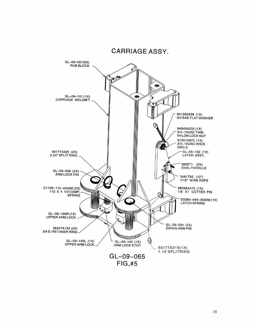
91247A722 ½-13UNC HHCS x 2 ½” 2 95462A033 ½-13UNC Hex Nut 4 98306A175 1/8” Cotter Pin x ¾” 2 98338A175 5/16 x 1 ½ Clevis Pin 2 98410A132 0.937 Dia. External Retainer Ring 3 GL-09-009 6” Cable Pulley 6 GL-09-065 Carriage Assy. 1 3896T1 Oval Ferrule 2 3461T82 1/16” Wire Rope x 12” 1 90126A036 ¾ SAE Flat Washer 1 90177A219 1.10” Split Ring 1 90177A225 2.24” Split Ring 2
91257A870 ¾-10UNC HHCS Grd. 8 1 94945A235 ¾-10UNC Thin Nylon Lock Nut 1 98338A475 1/8 Cotter Pin x 1” 1 98555A213-1.0 1” C-Retainer Ring 4 E0360-049-3500M 3/8” Latch Spring 1 ALIF-209-107 Upper Arm Lock 2 ALIF-209-158 0.112 x 5 ¼ Comp. Spring 2 ALIF-F209-099 Arm Lock Pin 2 GL-09-057 Nylon Rub Blocks 8 GL-09-094 Swing Arm Pin 2 GL-09-101 Carriage Weldm’t. 1 GL-09-102 Latch Assy. 1
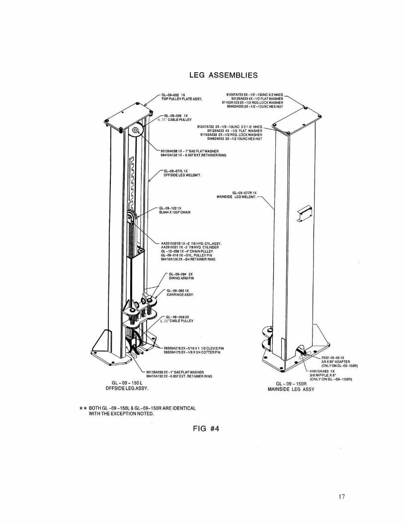
GL-09-077L Offside Leg Weldm’t. 1 GL-09-082 Top Pulley Plate Assy. 1 GL-09-122 BL644 x 125 Pitch Chain 1 GL-09-150R Mainside Leg Assy. 1 AA2515021B 2 /78 Hyd. Cylinder Assy. 1 98410A128 ¾” Dia. External Retainer Ring 2 AA2515021 2 7/8 Hyd. Cylinder 1 GL-09-016 Cyl. Pulley Pin 1 GL-09-056 4” Chain Pulley 1 2502-06-06 3/8 FNPT x 3/8MJIC 90 Deg Adapter 1 44615K483 3/8 Nipple x 6” 1 5503-06-06 3/8 MNPT x 3/8FNPT 45 Deg. Adapter 2 90126A033 ½” SAE Flat Washer 8 90126A038 1” SAE Flat Washer 3 91102A033 ½” Reg. Spring Washer 4 91247A720 ½-13UNC HHCS x 2” 2
24
91247A722 ½-13UNC HHCS x 2 ½” 2 95462A033 ½-13UNC Hex Nut 4 98306A175 1/8” Cotter Pin x ¾” 2 98338A175 5/16 x 1 ½ Clevis Pin 2 98410A132 0.937 Dia. External Retainer Ring 3 GL-09-009 6” Cable Pulley 6 GL-09-065 Carriage Assy. 1 3896T1 Oval Ferrule 2 3461T82 1/16” Wire Rope x 12” 1 90126A036 ¾ SAE Flat Washer 1 90177A219 1.10” Split Ring 1 90177A225 2.24” Split Ring 2
91257A870 ¾-10UNC HHCS Grd. 8 1 94945A235 ¾-10UNC Thin Nylon Lock Nut 1 98338A475 1/8 Cotter Pin x 1” 1 98555A213-1.0 1” C-Retainer Ring 4 E0360-049-3500M 3/8” Latch Spring 1 ALIF-209-107 Upper Arm Lock 2 ALIF-209-158 0.112 x 5 ¼ Comp. Spring 2 ALIF-F209-099 Arm Lock Pin 2 GL-09-057 Nylon Rub Blocks 8 GL-09-094 Swing Arm Pin 2 GL-09-101 Carriage Weldm’t. 1 GL-09-102 Latch Assy. 1
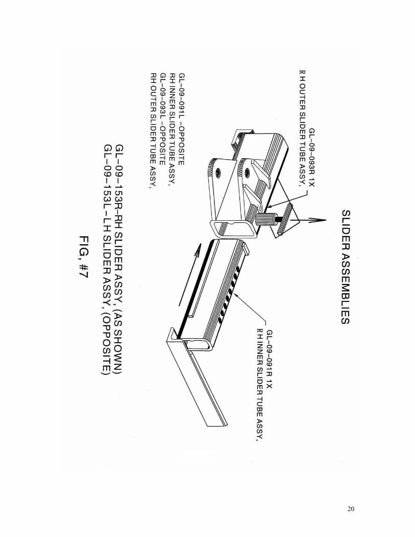
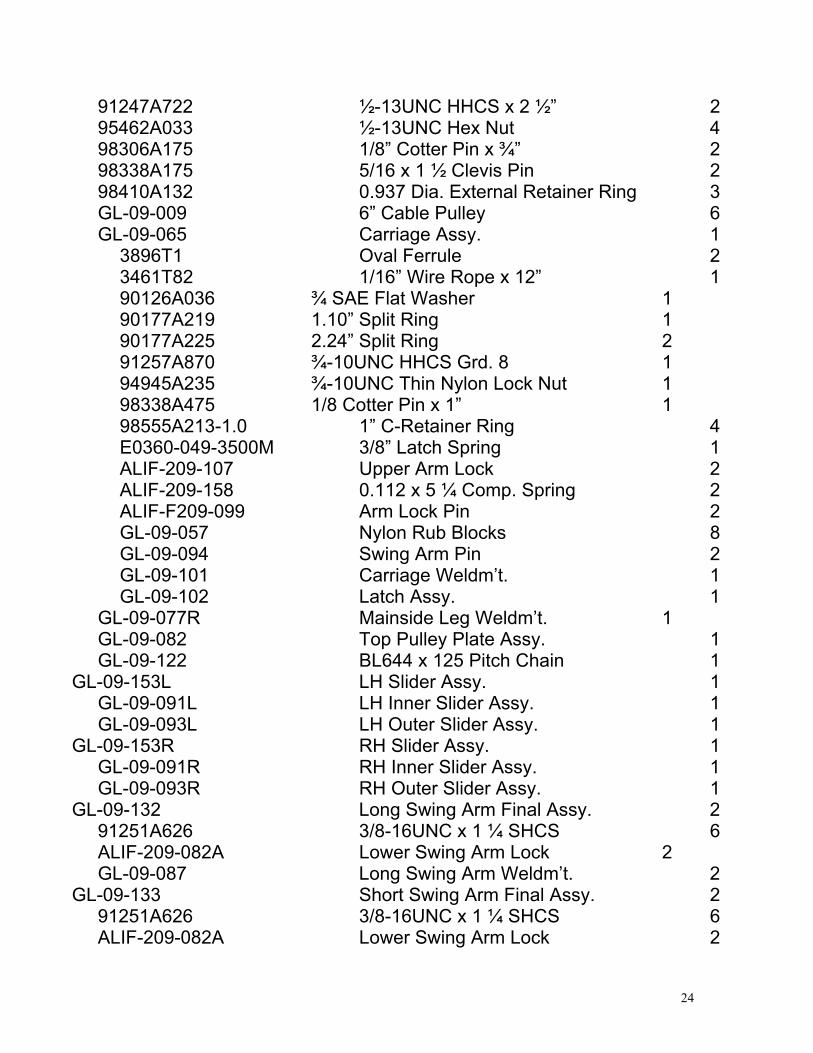
GL-09-077R Mainside Leg Weldm’t. 1 GL-09-082 Top Pulley Plate Assy. 1 GL-09-122 BL644 x 125 Pitch Chain 1 GL-09-153L LH Slider Assy. 1 GL-09-091L LH Inner Slider Assy. 1 GL-09-093L LH Outer Slider Assy. 1 GL-09-153R RH Slider Assy. 1 GL-09-091R RH Inner Slider Assy. 1 GL-09-093R RH Outer Slider Assy. 1 GL-09-132 Long Swing Arm Final Assy. 2 91251A626 3/8-16UNC x 1 ¼ SHCS 6 ALIF-209-082A Lower Swing Arm Lock 2 GL-09-087 Long Swing Arm Weldm’t. 2 GL-09-133 Short Swing Arm Final Assy. 2 91251A626 3/8-16UNC x 1 ¼ SHCS 6 ALIF-209-082A Lower Swing Arm Lock 2

25
GL-09-104 Short Swing Arm Weldm’t. 2
TRUCK OPTION GL-09-083 Swivel Pad Assy. 2 90126A029 ¼ SAE Flat Washer 4 90473A029 ¼-20UNC Hex Nut 4 92670A744 ¼-20UNC Elevator Bolt 4 GL-09-013 Rubber Pad 2 GL-09-132 Long Swing Arm Final Assy. 2 91251A626 3/8-16UNC x 1 ¼ SHCS 6 ALIF-209-082A Lower Swing Arm Lock 2 GL-09-087 Long Swing Arm Weldm’t. 2 GL-09-095 Truck Adapter Assy. 4 90126A029 ¼ SAE Flat Washer 8 90473A029 ¼-20UNC Hex Nut 8 92670A744 ¼-20UNC Elevator Bolt 8 GL-09-013 Rubber Pad 4 ***Note: All hardware unless specified is grade 2. All hardware is zinc coated unless specified.