GK 24-en 05-11.1 - Weger · 21 3 Range of products: - Complete Air Conditioning Equipment for...
24
en
Transcript of GK 24-en 05-11.1 - Weger · 21 3 Range of products: - Complete Air Conditioning Equipment for...

en

Werk in Ungarn
In 1977, the founder, owner and leader of the company, Mr. Walter Weger started with the production of Air Ducts and Air Distribution Components. As installation company in the local area for the catering trade the company WEGER was grown up and well known as a faithfull partner in all questions of air trading. The constantly growing internal demand of Air Handling Units caused finally thestart of a own production of the AHU’s. Many different detai-led solutions flowed into the development of the new device series of DIWER, which where then introduced in the year 1992. By the constantly growing customer require-ments as well as the guidance of an internal QM - System ISO 9001-2000, all our products are subject to a constant research and deve-lopment process.
Production plant in Kiens - South Tyrol
Production plant in Hungary

2
Our production techniques are state of the art – as is our fully automatic punching and laser centre. Progress and success are due significantly, however, to the commitment of our motivated employees

213
Range of products:
- Complete Air Conditioning Equipment for filtering, Heating, Cooling, Humidifying, and Air Drying
- Air Handling Units with Heat Recovery- Air Handling Units for behind sealing installation- Air Handling Units for Roof Top Mounting or Outside
Installation- Air Handling Units in Hygienic Execution for Hospitals
and Clean Rooms- Air Ducts and Distribution components- Planning Support and Engineer Consultation

44
Weger climate technologyfor the highest demands
All over the world where the right atmospheric environment is called for – for offi ce buildings, commer-cial buildings, public institutions, in catering and in industry. Even the custom air conditioning units for the meat and food stuffs processing industry and for ship building carry our name. Weger – air solutions.

35
2
Profil thermisch getrennt
Profil thermisch getrennt
EnergieefizienzklasseEnergieefizienzklasse
BBnach RLT-Richtlinie 01
Bau
must
re
geprü
ft
Produti
nk
o
überwa
hc t
RLT-Richtlinie 01
EnergieefizienzklasseEnergieefizienzklasse
AAnach RLT-Richtlinie 01
u
r
Bau
mst
erü
ft
gep
Pdu
ti
ro
kon
üe
h
brw
act
RLT-Richtlinie 01
EnergieefizienzklasseEnergieefizienzklasse
A+A+nach RLT-Richtlinie 01
r
Bau
must
erü
ft
gep
Pdu
t
ro
kion
üe
h
brw
act
RLT-Richtlinie 01
Double-walled Air Handling Units in modular construction for and airthight construction method allows for absolutely air conditioning for horizontal or vertical mounting, completely smooth walls inside the Air Handling Unit and easy dismante-detachable structure of housing without welding and rivet ling of the wall panels can be supplied if requested with a joints. plastic coated colour finish and inner panels can be made of Each module consists of a strong self supporting frame stainless steel or aluminium if required.construction and double walled, insulated panels which The service access doors are made in a similar construction makes each module suitable for horizontal or vertical as the panels and we fit strong locking handles and adjustab-mounting. The suo´pport frame is made from secialy extruded le, sturdy metal hinges to ensure an airthight door seal over and anadized aluminium profiles with grooves for mounting the whole life span of the Air Handling Unit.the rubber sealing gasket and optically pleasing rounded Panels which have to be complete removed for service corners on the outer edges. These frames are connected with access are held by strong screw lugs on the outside and are cast aluminium corner units and secured with the use of a fitted with grab handels on the outside. Doors on larger units single screw in each corner post, which makes for easy have handles for opening also on the inside.dismanteling at the point of installation if so required. The wall, Doors of the Air Handling Unit modules which are under floor, and roof panels are made of double wall construction pressure have an additional catch system to prevent with galvanized sheet metal on the inside and outside with 40 accidental opening while in operation.mm mineral wool insulation between. All Air Handling Units can be supplied with a galvanized steel The insulation is non flammable and conforms to the fire class sub-frame if requested.A1 and DIN 4102. If requested the panels can be insulated For larger Air Handling Units detatchable lifting eyes for easy with rigid Polyurethan foam to fire class B2 and standard DIN hanlding are supplied as standard.4102. The individual Air Handing Unit modules can be connected The panel edges have a 90 degree step to fit airthight into the with each other simply by using the supplied sealing strip, frame and are held in place by special snap aluminium jam connection bracket and screws.strips which slot into grooves in the support frame. No rivets or screws are necessary to hold the panels in place. Our special
Thermal breakProfile
Thermal breakProfile
StandardProfileStandardProfile
The WEGER Air Handling Untits are tested in accordance with the specifications EN 1886 and fit out with the certificate of hygienic and therefore suitable for the use in the healthcare system and food industry.

Ventilatorelement
Fan section
High performance DIDW centrifugal fan with either forward or bac-kward curved blades, The casing is made of galvanized sheet steel with aerodynamically formed inlet openings.
Depending on the fan size, the rotor is either made of galvanized steel or durable polyamide. The rotor is statically and dynamically balanced according to min. Q 6.3 as specified on VDI 2060.
We use special low noise bearings which have an operating life span of at least 20.000 hours. The fan and motor is mounted on a common base frame which is made from steel profiles. The base frame is fitted with vibration dampers (rubber or spring isolators) and these connected to the Air Handling Unit. Floor frame without transmittion of unwanted vibration.
The electro motor is mounted onto an adjustable belt tensioning base which has sliding rails and a central adjusting screw. The electro motors are of the totaly enclosed type and according to standard IP 54 and insulation class F.
We can supply single speed, two speed or stepless motors on re-quest. We fit antistatic belt drives with cast iron or aluminium taper lock pullies.
Heating coil section
Quality heat exchangers with copper tubes and aluminium fins are used in order to provide maximum thermal transmission. The hea-ting coils are made with frames of galvanized steel and are pressure tested to 30 bar.
The coil connection spigots are threaded and an air thight rubber seal is provided where they pass through the Air Handling Unit panel. The heat exchangers can easily be withdrawn for servicing from the Air Handling Unit via service panels and guide rails.
Options:
Coil type Cu/Cu, Cu/Al coated, Cu/Cu tinned, Fe/Al, galvanized steel, stainless steel
Cooling coil section
The coil construction and mounting features are the same as descri-bed in the heating coil section. In addition, this section features a conedsate drain pan made from stainless steel and a 1 inch drain spigot on the service side. If required droplet eliminators with plastic separator blades will be fitted and provision is made that the whole unit and the drain pan can be withdrawn from the Air Handling Unit via an access door and guide rails for cleaning.
Frost protection frame
A galvanized steel frame for mounting temperature sensors is instlled on rails between the heating and the cooling coil and can be withdrawn from the side of the Air Handling Unit.
6

7
Flat filter section
Filter medium according to EU 3 and DIN 24185 (B2) with a gravimetric efficiency of 87,5 % is mounted on flat or V-shaped carrier frames in order to provide an increased surface area for high dust storing and separation capacity for easy maintanance, the filter cells can be withdrawn on the service side of the Air Handling Unit by the means of a removable service panel or access door. gravimetrischer Abscheidegrad 87,5 %. Alternatively the filter cartriges are also available in variations in types e.g. with aluminium wire mesh as filter medium or even in higher filter grades (G4).
Bag filter section
The filter cells are equiped with high quality baga filters which have a temperature resistance of up to 90 °C, are self supporting and conform to DIN 24185 and EUROVENT norms. The bag filters are held in place by frames made of galvanized steel and are mounted air thight according to DIN 1946 with quick fastening spring clips.
The filter cells can either be withdrawn from the service side of the Air Handling Unit for filter changing or access is provided by a service compartment on the dust side of the filter
Sound attentuator
Splitter thickness 200 mm with high sound absorbtion properties and suitability properties and suitability for air speeds up to 20 m/sec are used as standard. The frames and the anti- resonance plates are made from galvanized sheet steel. The gap between the splitter is 105 mm.
Options:
Splitters for hygienic application
Air flow caps on the leading and trailing edges
Housing and frames made from stainless steel
Special applications like transparent accustic foil, wire guard
According VDI 6022
5
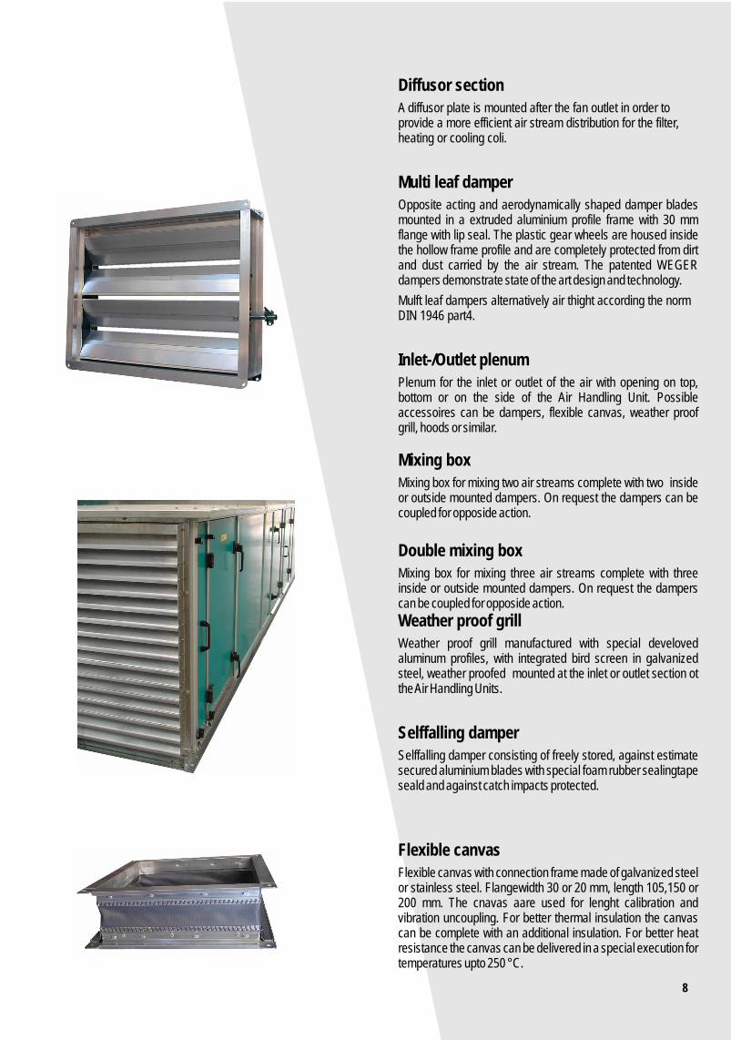
Diffusor section
A diffusor plate is mounted after the fan outlet in order to provide a more efficient air stream distribution for the filter, heating or cooling coli.
Multi leaf damper
Opposite acting and aerodynamically shaped damper blades mounted in a extruded aluminium profile frame with 30 mm flange with lip seal. The plastic gear wheels are housed inside the hollow frame profile and are completely protected from dirt and dust carried by the air stream. The patented WEGER dampers demonstrate state of the art design and technology.
Mulft leaf dampers alternatively air thight according the norm DIN 1946 part4.
Inlet-/Outlet plenum
Plenum for the inlet or outlet of the air with opening on top, bottom or on the side of the Air Handling Unit. Possible accessoires can be dampers, flexible canvas, weather proof grill, hoods or similar.
Mixing box
Mixing box for mixing two air streams complete with two inside or outside mounted dampers. On request the dampers can be coupled for opposide action.
Double mixing box
Mixing box for mixing three air streams complete with three inside or outside mounted dampers. On request the dampers can be coupled for opposide action.
Weather proof grill
Weather proof grill manufactured with special develoved aluminum profiles, with integrated bird screen in galvanized steel, weather proofed mounted at the inlet or outlet section ot the Air Handling Units.
Selffalling damper
Selffalling damper consisting of freely stored, against estimate secured aluminium blades with special foam rubber sealingtape seald and against catch impacts protected.
Flexible canvas
Flexible canvas with connection frame made of galvanized steel or stainless steel. Flangewidth 30 or 20 mm, length 105,150 or 200 mm. The cnavas aare used for lenght calibration and vibration uncoupling. For better thermal insulation the canvas can be complete with an additional insulation. For better heat resistance the canvas can be delivered in a special execution for temperatures upto 250 °C.
8

9
Range selection diagramm für DW 64 - 3125

10
Belt driven fan sectionl Fan outlet position
48
Dimensions
L
V
a
b
1 2
3 4
5 6
AHU type
64
66
96
126
99
129
1212
1512
1812
1515
1815
1818
2118
2518
2121
2521
2525
2825
3125
160
200
225
250
250
315
355
450
450
450
500
560
630
630
630
800
900
900
900
180
225
250
280
280
355
400
500
500
500
560
630
710
710
710
900
1000
1000
1000
215
250
280
315
315
400
450
560
560
560
630
710
800
800
800
1000
1120
1120
355
450
500
630
630
630
710
800
400
Fan sizesDW
160
180
215
200
225
250
280
315
355
400
450
500
560
630
710
800
900
1000
1120
1-6
1-6
1-6
1-6
1-6
1-6
1-6
1-6
1-6
1-6
1-6
1-2
3-6
1-2
3-6
1-2
3-6
1-2
3-6
1-2
3-6
1-2
3-6
1-2
3-6
1-2
3-6
762
915
915
915
915
915
915
915
1220
1220
1220
1220
1525
1525
1525
1525
1525
Fanoutletposition
Motor sizes
<112Fan-size
132
1220
1220
1220
1220
1220
1525
1525
1525
1525
1830
1525
1830
1830
1830
160-180
1525
1525
1525
1830
1525
1830
1525
1830
1830
2135
2135
2135
2135
2440
2135
2440
2440
2745
200
1525
1830
1830
1830
1830
1830
2135
2135
2135
2135
2135
2440
2440
2745
2440
2745
225
1830
1830
1830
2135
2135
2135
2135
2440
2135
2440
2440
2745
2440
2745
250
2440
2745
2440
2745
2745
3050
280
2440
2745
2440
2745
2745
3050
Fan casing length L
a x b
205
230
322
260
290
320
360
400
450
510
570
640
640
732
715
818
801
915
898
1024
1007
1147
1130
1284
1267
915
1421

11
3
1
2
7
4
6
5
hb
48
A48150 130 70 60
h1 b48
Duct connection Inlet section A Mixing section M
3
1
2
4
6
5
hb
48
A48
Double Mixing sectionl M2
3
4
6
5
hb
48
A2
3
hb
96
6
5
4
Plenum L
on request48
L48305457610762
With service door
Dimensions
Diffussor-section
P
P
Sound attentuator SD
610915
1220152518302135
Plan-filter sectionl
PF
152
Bag-filter section
TF
457610762
Absolute-filter sectionl
AF
305min 610 610 min 610
Active carbon-filter section
AKF
LB
R1W1J1S1
150 130 60
h b48
R2J2S2

12
Heating coilsection
EH Cooling coilsection
KH TA Steam Humidifyer DBDroplet-seperator
152
TA
FSAnti Frostframe
152
Removable
305
EEElectric-heater
TA
TA
91512201525
610
Honey Comb- Humidifyer
With anti frost frame
TA
AHU type
64
66
96
126
99
129
1212
1512
1812
1515
1815
1818
2118
2518
2121
2521
2525
2825
3125
h h1 b A A2 P
230
230
230
340
455
455
570
680
680
780
780
900
900
900
1015
1130
1240
1240
1240
474
667
667
667
972
972
1277
1277
1277
1582
1582
1887
1887
1887
2192
2192
2497
2497
2497
610
610
915
1220
915
1220
1220
1525
1830
1525
1830
1830
2135
2440
2135
2440
2440
2745
3050
230
230
230
340
455
455
570
680
680
780
780
900
900
900
1015
1130
1240
1240
1240
556
556
556
776
1006
1006
1236
1456
1456
1656
1656
1896
1896
1896
2126
2356
2576
2576
2576
457
610
610
610
610
762
762
915
915
915
915
1220
1220
1220
1220
1220
1220
1525
1525
AHU arrangement example AHU type DIWER 1818
1830 189648 48
152 305 457 183031 31 3131
48 48
Divided for transport
6786
305457
4-6RR
7-8RR
457610
4-6RR
7-8RR
152305
1-3RR
1-6RR
4-6RR
=< DW1212
<= DW1512
DIWER
305
see upside
Reserves of right for technical modificationsThe indicated dimensions are not binding. The flexible WEGER production permits device manufacturing after measure.

13
Energie recovery systems
extanst air
autside air
supply air
return air
Heat recovery systems
If possible, each Air Handling Unit shut be complete with a heat recovery system. There are different types of heat recovery systems. The base principe of function of heat recovery systems is to take energy form the exhaust air and to put this energy to the fresh air. We are able to offer all conventional heat recovery systems and can provide assistance and technical documentation to enable the customer to select the most suitable and efficient system for his application some of the systems we offer are:
Through the use of energy recovery systems you do not only save for cash, you protect also the environment.
Regenerative Energie recovery system
Coil Loop System
Function as described beforeAdvantages:- small space for installation needed- A.H.U. for return- and supply air can be mounted on differend positiones- Air streams can't be mixedDisadvantages:- low efficiency- electrical power is needed (for circulating Pump)
return air
fresh air
supply air
exhaust air
return air
fresh air
supply air
exhaust air

14
Plate heat exchanger
Function as described before Advantages:- No energy for action is needed- No smell transfer between the air streams- High efficiencyDisadvantages:- Rel. big space is needed- Exhaust- and supplyair must cross- No humidity exchange
Rekuperative Energie recovery system
Plate heat exchanger are available in different executions
1. Without bypass.2. With integrated bypass with damper:
It could occure that at deep temperatures in the supply airside, the condensate, which is formed in the exhaust air, freezes. Therefore we recommend the use of plate heat exchangers with bypass. So the cold supply air can pass through the bypass section, defrost with warm exhaust air and the normal heat recovery can be recreated faster.
Materials of plate heat exchangers:-Aluminium-Aluminium with epoxy resin coating-Stainless steel V2A-Stainless steel V4A
The plate heat exchangers in the executions aluminium coated and stainless steel are suitable for the use in air handling units for swimming pools.
Energie recovery systems
return air
fresh air
supply air
exhaust air
fresh air
exhaust air
return air
supply air
15
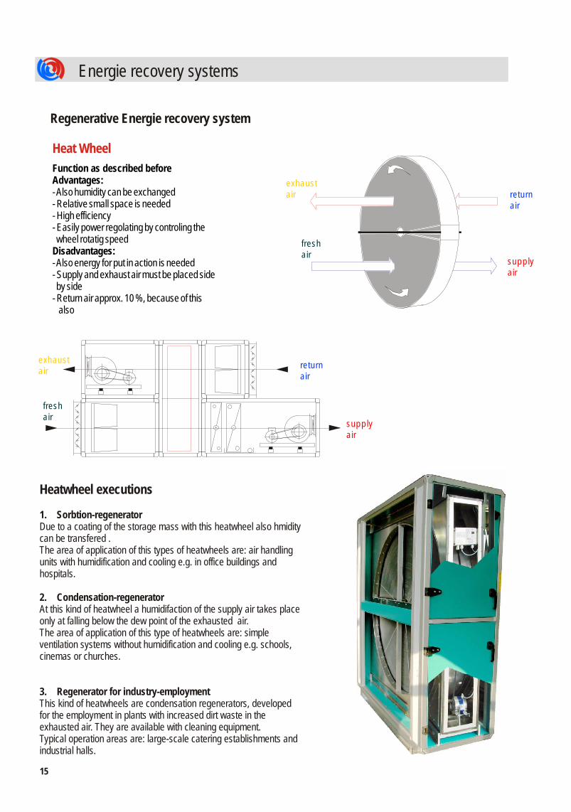
Heatwheel executions
1. Sorbtion-regeneratorDue to a coating of the storage mass with this heatwheel also hmidity can be transfered .The area of application of this types of heatwheels are: air handling units with humidification and cooling e.g. in office buildings and hospitals.
2. Condensation-regeneratorAt this kind of heatwheel a humidifaction of the supply air takes place only at falling below the dew point of the exhausted air.The area of application of this type of heatwheels are: simple ventilation systems without humidification and cooling e.g. schools, cinemas or churches.
3. Regenerator for industry-employmentThis kind of heatwheels are condensation regenerators, developed for the employment in plants with increased dirt waste in the exhausted air. They are available with cleaning equipment.Typical operation areas are: large-scale catering establishments and industrial halls.
Heat Wheel
Function as described beforeAdvantages:- Also humidity can be exchanged- Relative small space is needed- High efficiency- Easily power regolating by controling the wheel rotatig speedDisadvantages:- Also energy for put in action is needed- Supply and exhaust air must be placed side by side- Return air approx. 10 %, because of this also
Regenerative Energie recovery system
Energie recovery systems
return air
fresh air
supply air
exhaust air
return air
exhaust air
fresh air
supply air

16
Regenerative energy recovery system
Function:Accubloc is a regenerative heat exchanger with 2 or more static, not movable, heat packages made of highly warm-sensitive accumulator mass. By a before and after the heat package mounted damper system alternating the package will be loaded during simultaneous the other one will be unloaded. For this, the dampers are switched in regular intervals.
Depending upon assigned material a large part of humidity can be recovered also at the same time.
Accubloc
Phase1The warm room air (exhaust air) will be brought by means of the damper system over the accumulator 1 and heats this. At the same time cold fresh air (supply air) flows through the in Phase 2 heated accumulator 2 and warms up the air thereby nearly to ambient
Phase2By switching the damper cold fresh air (supply air) will be brought over the accumulator 1 heated in Phase 1. The warm exhaust air flows through the accumulator 2 and heats this.
1
2
2
1
Energie recovery systems
return air
supply air
fresh air
exhaust air

17
UML
UML
Energie recovery systems
Regenerative Energie recovery system
Heat Pipe
Function as described beforeAdvantages:- small space for installation needed- no energy for action is needed- no smell transfer between the air streansDisadvantages:- low efficiency- fresh and exhaust air must be aligned side by side and the warm air stream must be positioned lower than the cooler air stream
Heat Pipe
Calculation of heatpipes on demand
AHU one on the top of the other
AHU side by side
fresh air
supply air
return air
exhaust air
return air
fresh air
supply air
exhaust air
return air
fresh air
supply air
exhaust air
18
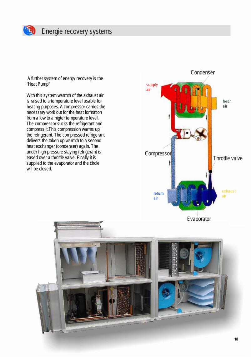
A further system of energy recovery is the “Heat Pump”
With this system warmth of the axhaust air is raised to a temperature level usable for heating purposes. A compressor carries the necessary work out for the heat formation from a low to a higter temperature level. The compressor sucks the refrigerant and compress it.This compression warms up the refrigerant. The compressed refrigerant delivers the taken up warmth to a second heat exchanger (condenser) again. The under high pressure staying refrigerant is eased over a throttle valve. Finally it is supplied to the evaporator and the circle will be closed.
Evaporator
Condenser
CompressorThrottle valve
Energie recovery systems
fresh air
supply air
return air
exhaust air

08
or m120 m
50
8
21
0b
i m
as
xm
50
0
m
60 X
60
183
Unit mounting frames
Standard unit mountng frame:
Optional deflektor skirting
Optional double skin insulated:
The different baseframes can aslo be combinated. For example baseframe insulated, 300 mm high,supporting panel 100 mm width with dropper nose (see example on the next page).
Connection of the modules at the base frame
Connect the several modules at the base frame either with the supplied screws M8 x 30 or M10 x 30.
Length andangle of
inclinationon request

b
c
Dachhaut (bauseits)
20
Abkittung
<= 3600 mm
<=. 3600 mm
> 3600 mm
1. Standard weatherproof roof
2. Single pitch insulated roof
3. Double pitch insulated roof
sealing ring
Roof membrane (Aluminium 1,5 mm)
Screw with
Connection of the roof-mounted units
The connection of roof-mountd units follows in3 steps:a) Sealing the unit flanges between the several modulesb) Connection with the srews (look the picture)c) Assembly of the sliding stripe (look the picture)
- To exactly position the unit on the base it can be manhandled over a cedntrally positioned bar using a lever action In this event the bar must only bear against the base frame.
sliding border
Roof designs
Unit does not work as roof replacement
baseframe insulated
Cut by a weatherproof unit with standard flat roof
mafund- orcork layer (supplied by others)
roo (supplied by others)f
Deflektor skirting
roof membrane(supplied by others)

2221213
some details

NetNetIIM
MA
EN TA SG YE S M E TN
Worldwide...Worldwide...EnergieefizienzklasseEnergieefizienzklasse
A+A+nach RLT-Richtlinie 01
Ba
uster
umgep
rüft
Produktion
überwacht
RLT-Richtlinie 01
GK 24-en_06-11.1
Automotive
Pharmaceutical industry
Banking/Services
Food industry
Retail market
Industry
ReferencesS Y S T E M C E R T I F I E D
ISO 9001:2008 OHSAS 18001:2007RT-05

WEGER WALTER Srl
I- 39030 CHIENES (BZ)
Tel. +39 0474 565253 Fax. +39 0474 565011
Mail: [email protected] Internet: www.weger.it
Zona Artigianale 5
ii
A company from