Gis
319
Introduction to Gas Insulated Switchgear and Substations Dr. M. Mohana Rao BHEL Corporate R&D Hyderabad E-mail: [email protected]
-
Upload
veeranna1981 -
Category
Documents
-
view
157 -
download
2
description
Gis
Transcript of Gis
Introduction to Gas Insulated
Switchgear and Substations
Dr. M. Mohana Rao
BHEL Corporate R&D
Hyderabad
E-mail: [email protected]

Cable Technology
• 1960s-1980s: Fluid filled systems for HV and EHV
• 1980s-1990s: Low loss PPL systems to match the
paper laminate’s performance for EHV
• 1970s-1990s: Parallel development of XLPE system from
MV up to EHV 275kV XLPE cables in service.
In Japan 500 kV XLPE cables installed.
• 1970s-1990s: Gas-filled (SF6) short lengths installed. Many
lab models for higher voltages, including
three phase designs in a single duct. Also,
SF6/N2 mixtures attempted.
• 1970s-1990s: Low temp. cryogenic/supercon. designs tried.
witnessed the phenomenal growth in HTS
technology.
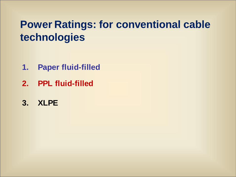
Power Ratings: for conventional cable
technologies
1. Paper fluid-filled
2. PPL fluid-filled
3. XLPE
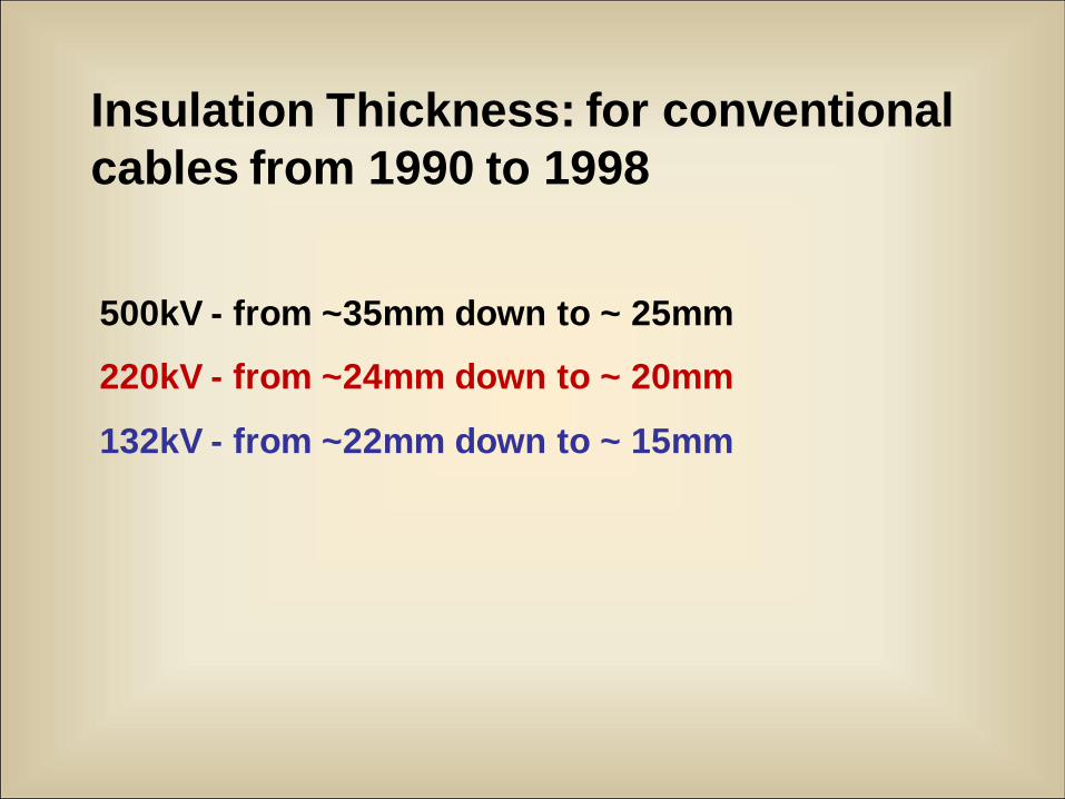
Insulation Thickness: for conventional
cables from 1990 to 1998
500kV - from ~35mm down to ~ 25mm
220kV - from ~24mm down to ~ 20mm
132kV - from ~22mm down to ~ 15mm
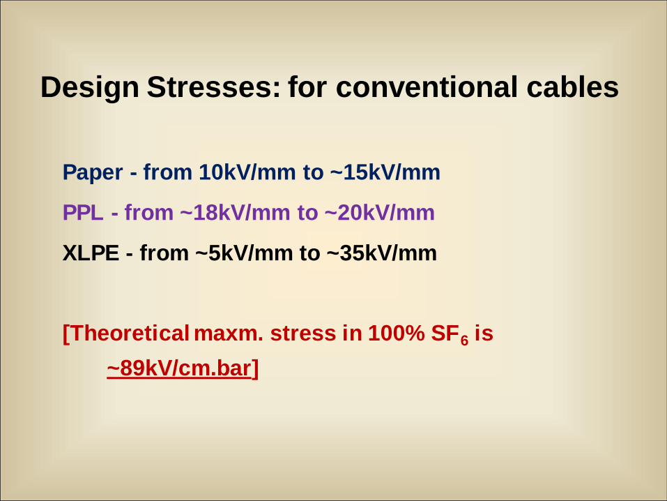
Design Stresses: for conventional cables
Paper - from 10kV/mm to ~15kV/mm
PPL - from ~18kV/mm to ~20kV/mm
XLPE - from ~5kV/mm to ~35kV/mm
[Theoretical maxm. stress in 100% SF6 is
~89kV/cm.bar]
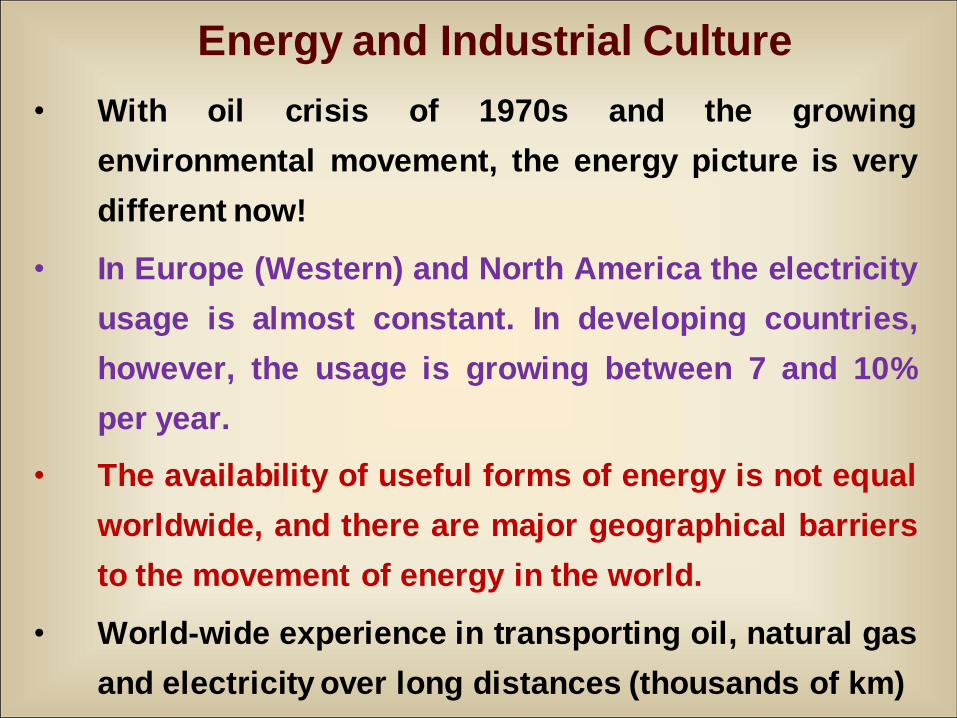
Energy and Industrial Culture
• With oil crisis of 1970s and the growing
environmental movement, the energy picture is very
different now!
• In Europe (Western) and North America the electricity
usage is almost constant. In developing countries,
however, the usage is growing between 7 and 10%
per year.
• The availability of useful forms of energy is not equal
worldwide, and there are major geographical barriers
to the movement of energy in the world.
• World-wide experience in transporting oil, natural gas
and electricity over long distances (thousands of km)
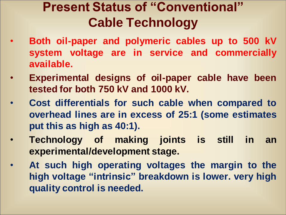
Present Status of “Conventional”
Cable Technology
• Both oil-paper and polymeric cables up to 500 kV
system voltage are in service and commercially
available.
• Experimental designs of oil-paper cable have been
tested for both 750 kV and 1000 kV.
• Cost differentials for such cable when compared to
overhead lines are in excess of 25:1 (some estimates
put this as high as 40:1).
• Technology of making joints is still in an
experimental/development stage.
• At such high operating voltages the margin to the
high voltage “intrinsic” breakdown is lower. very high
quality control is needed.
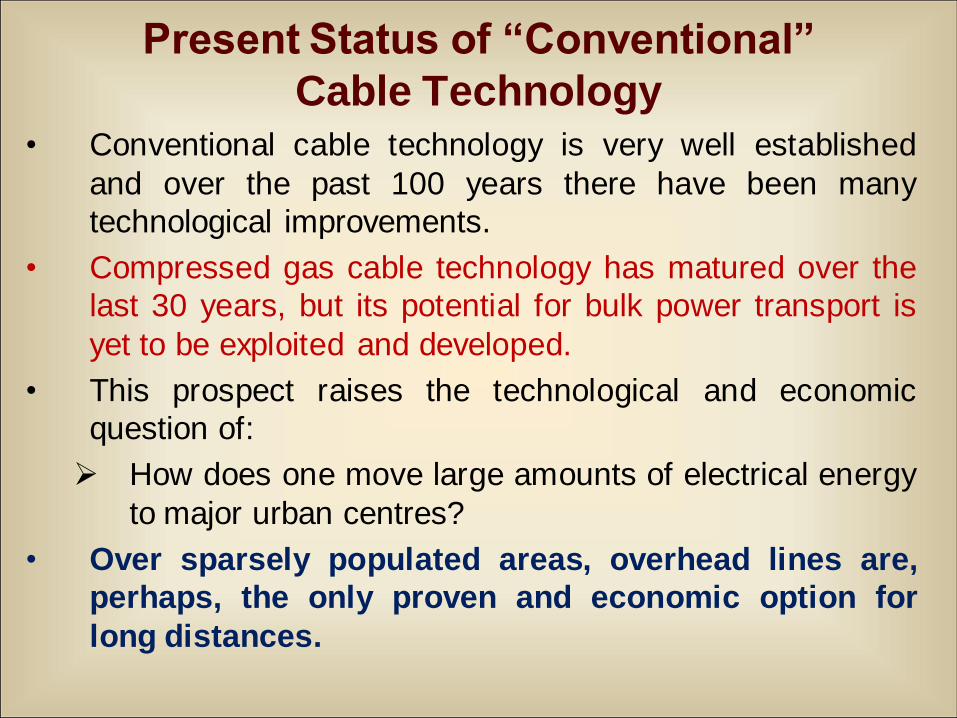
Present Status of “Conventional”
Cable Technology• Conventional cable technology is very well established
and over the past 100 years there have been many
technological improvements.
• Compressed gas cable technology has matured over the
last 30 years, but its potential for bulk power transport is
yet to be exploited and developed.
• This prospect raises the technological and economic
question of:
How does one move large amounts of electrical energy
to major urban centres?
• Over sparsely populated areas, overhead lines are,
perhaps, the only proven and economic option for
long distances.
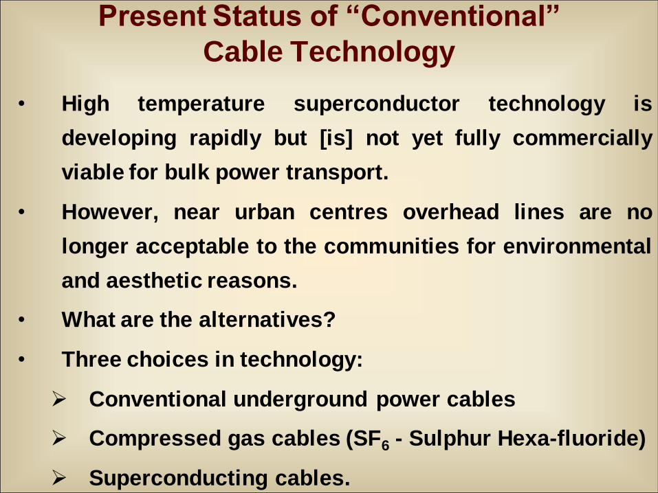
Present Status of “Conventional”
Cable Technology
• High temperature superconductor technology is
developing rapidly but [is] not yet fully commercially
viable for bulk power transport.
• However, near urban centres overhead lines are no
longer acceptable to the communities for environmental
and aesthetic reasons.
• What are the alternatives?
• Three choices in technology:
Conventional underground power cables
Compressed gas cables (SF6 - Sulphur Hexa-fluoride)
Superconducting cables.
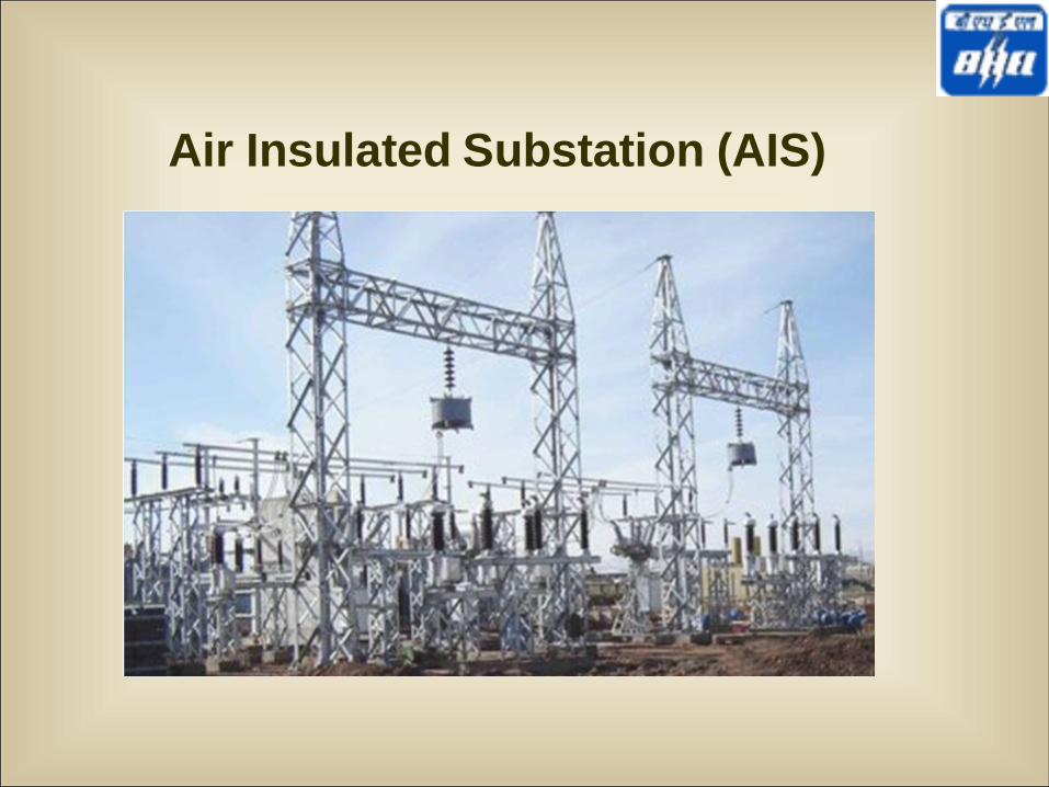
Air Insulated Substation (AIS)
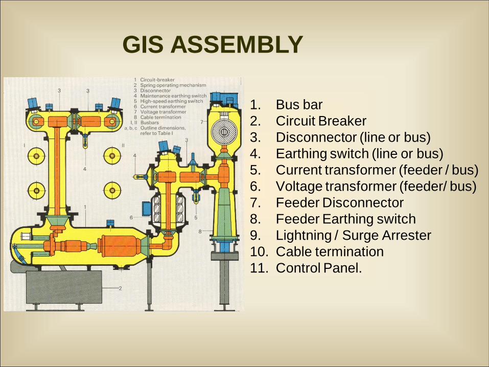
1. Bus bar
2. Circuit Breaker
3. Disconnector (line or bus)
4. Earthing switch (line or bus)
5. Current transformer (feeder / bus)
6. Voltage transformer (feeder/ bus)
7. Feeder Disconnector
8. Feeder Earthing switch
9. Lightning / Surge Arrester
10. Cable termination
11. Control Panel.
GIS ASSEMBLY

12/13/2010 12
Limitations of AIS
• Large dimensions due to statutory clearances and poor
dielectric strength of air
• Insulation deterioration with ambient conditions and
susceptibility to pollutants.
• Wastage of space above
• Life of steel structures
• Seismic instability
• Large planning & execution time
• Grounding-mat is essential for containing touch and
step potentials
• Hot line washing and regular maintenance of the
substation is essential, requires spares inventory and
man-power.
12/13/2010 13
The need for GIS
• Expansion / up-rating of existing s/s
• Non availability of sufficient space for s/s
• Difficult climatic and seismic conditions at site
• Urban site (high rise bldg.)
• High altitudes
• Limitations of AIS
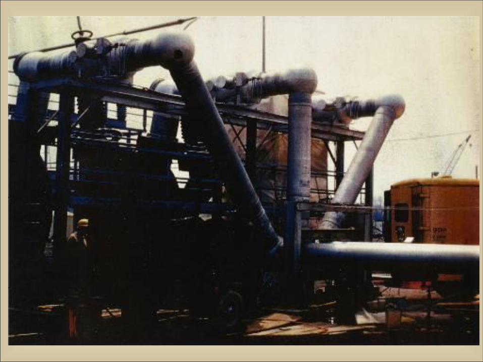
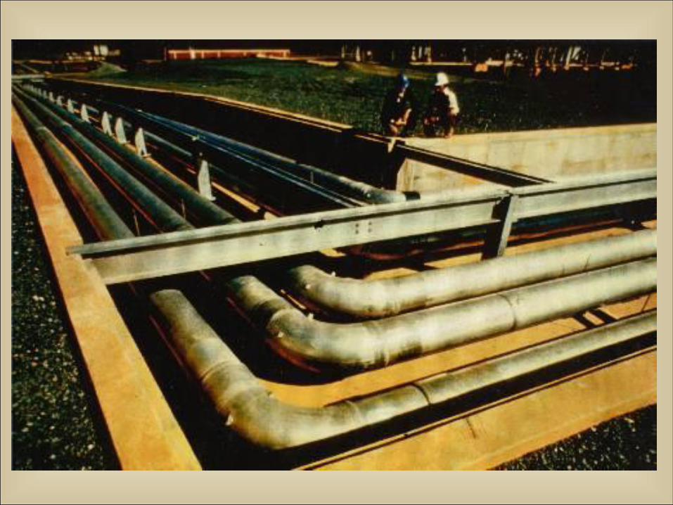
GITL
• In addition to the advantages listed above for GIS,
there is a need for non-aerial transmission lines near
urban areas.
• There are currently only two alternatives:
Underground cables–conventional or
superconducting, or
Gas Insulated Transmission Lines (GITL)
• GITL, compared to underground cables, have the
additional advantage of reduced ground surface
magnetic fields.
Clearances
Phase to ground clearance for 132 kV systems is
~1200 mm in air, compared to 80 mm in SF6 gas at
4.0 bar(g).
This gives a direct reduction in dimensions of the
high- voltage equipment- by 15
Consequently the size of SF6 insulated equipment
is around 6% that of air insulated equipment for this
voltage class (132kV)
Equipment size
To 30% for 33kV and below
To 15% for 66kV
To 6% for 132 kV to 170 kV and
To 4-5% for >245kV
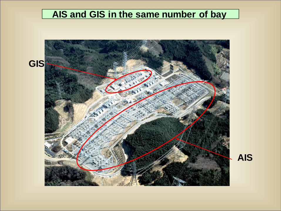
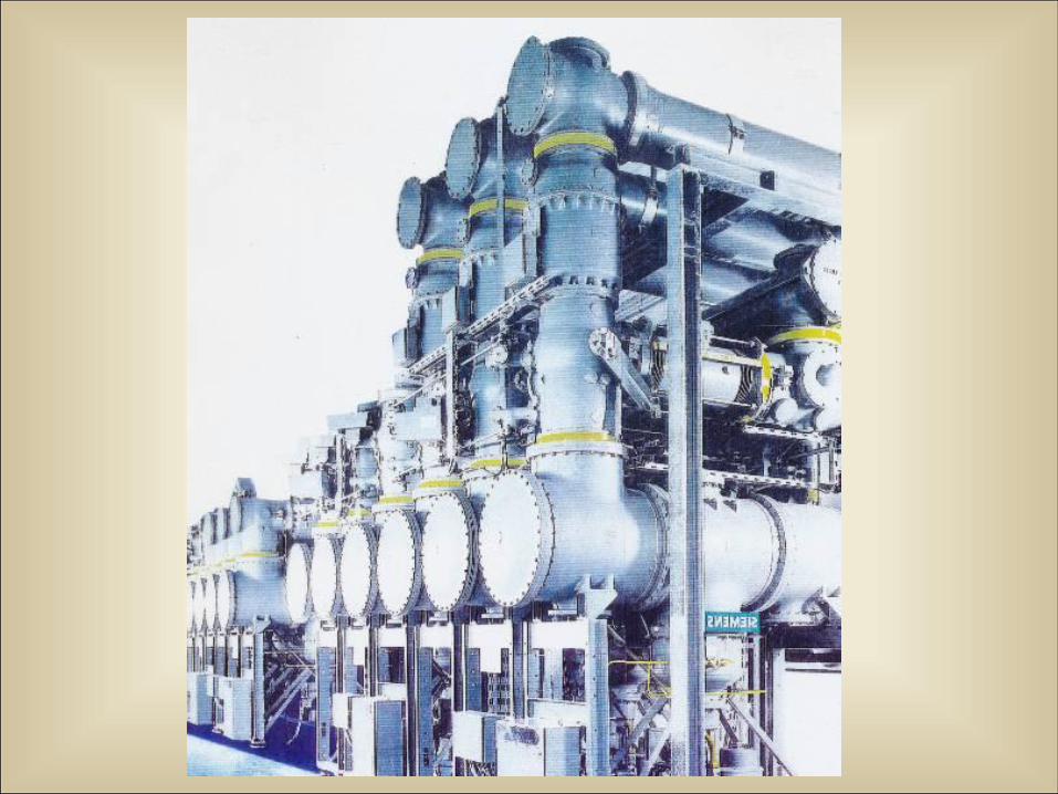
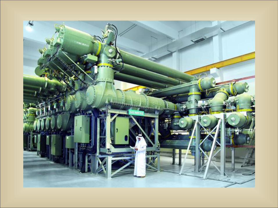
GIS
AIS
AIS and GIS in the same number of bay
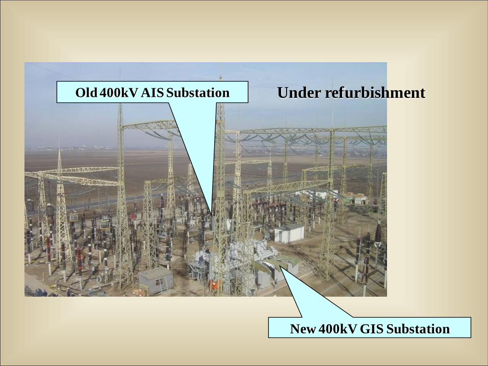
Old 400kV AIS Substation
New 400kV GIS Substation
Under refurbishment
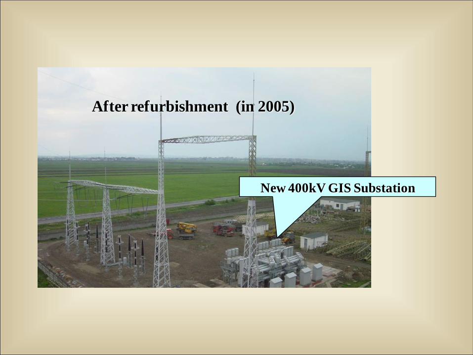
After refurbishment (in 2005)
New 400kV GIS Substation
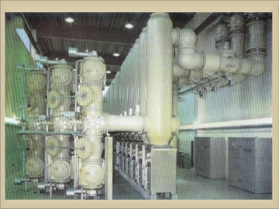
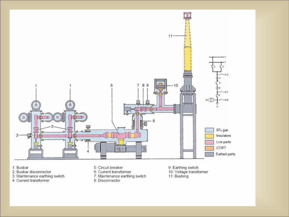
Design Features of GIS/GITL
• GIS/GITL installations have the usual components:
• Circuit breakers; disconnect, earthing/grounding
switches
• Current and voltage measuring devices
• Bus duct sections
• Variety of diagnostic/monitoring devices
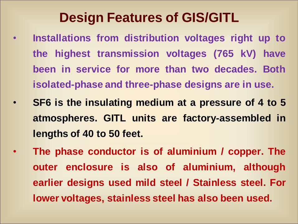
Design Features of GIS/GITL
• Installations from distribution voltages right up to
the highest transmission voltages (765 kV) have
been in service for more than two decades. Both
isolated-phase and three-phase designs are in use.
• SF6 is the insulating medium at a pressure of 4 to 5
atmospheres. GITL units are factory-assembled in
lengths of 40 to 50 feet.
• The phase conductor is of aluminium / copper. The
outer enclosure is also of aluminium, although
earlier designs used mild steel / Stainless steel. For
lower voltages, stainless steel has also been used.
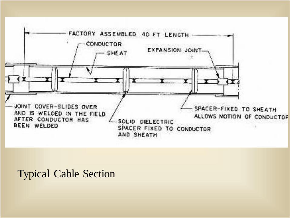
Typical Cable Section
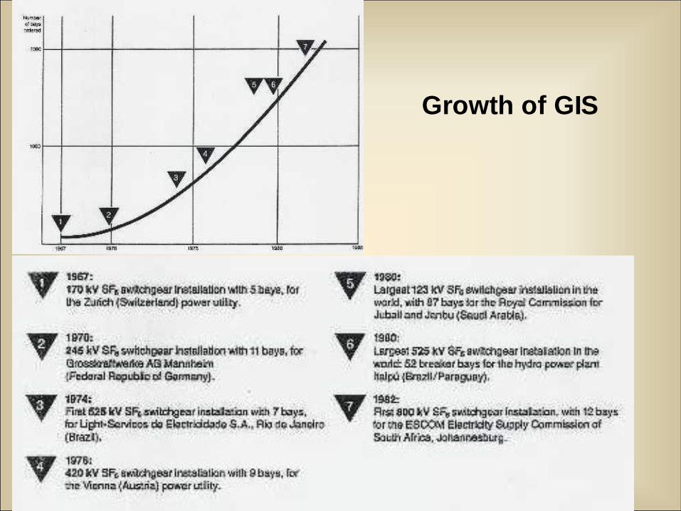
Growth of GIS
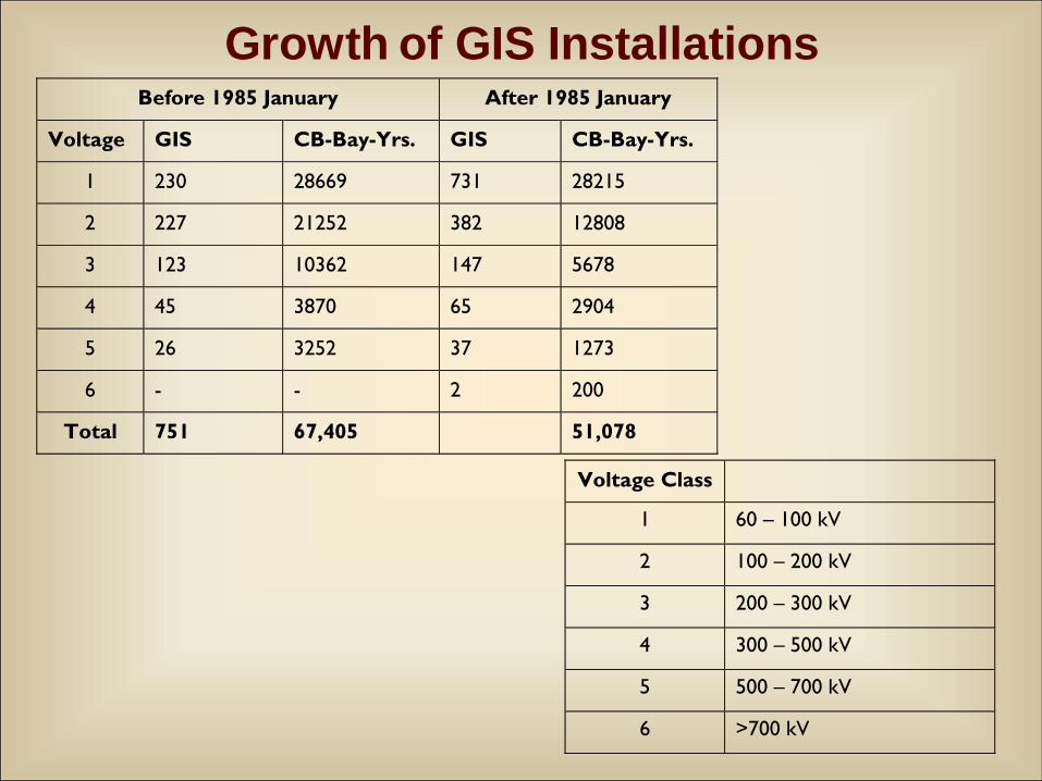
Growth of GIS InstallationsBefore 1985 January After 1985 January
Voltage GIS CB-Bay-Yrs. GIS CB-Bay-Yrs.
1 230 28669 731 28215
2 227 21252 382 12808
3 123 10362 147 5678
4 45 3870 65 2904
5 26 3252 37 1273
6 - - 2 200
Total 751 67,405 51,078
Voltage Class
1 60 – 100 kV
2 100 – 200 kV
3 200 – 300 kV
4 300 – 500 kV
5 500 – 700 kV
6 >700 kV

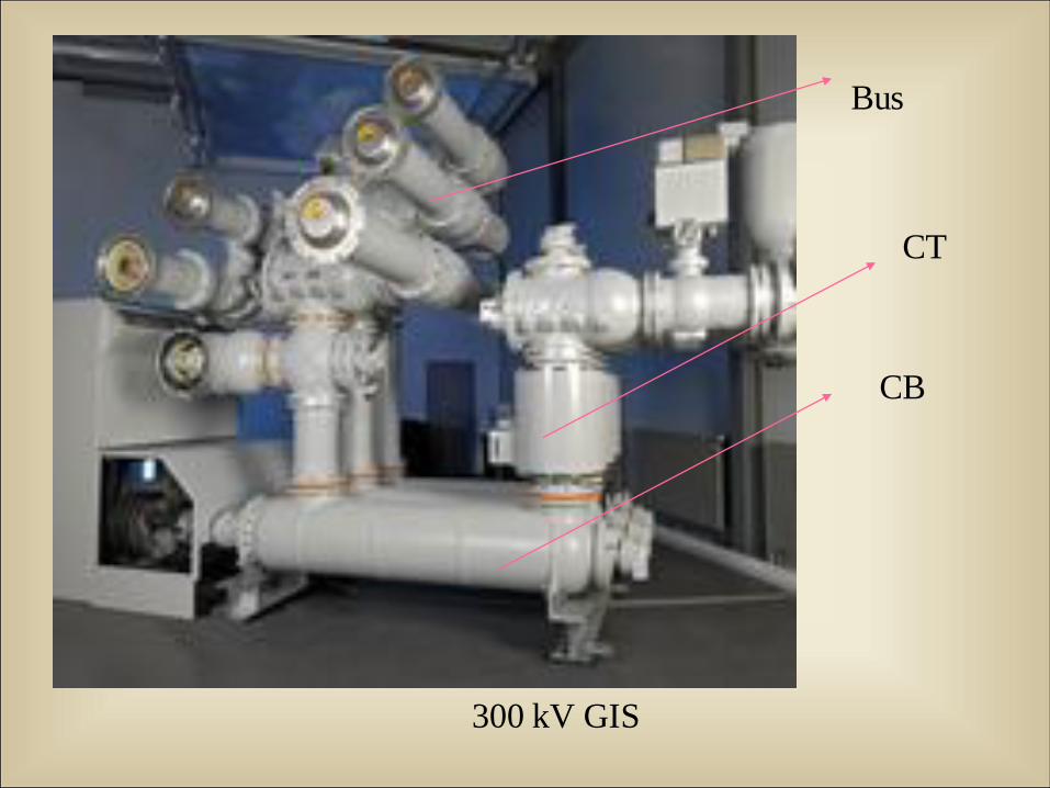
300 kV GIS
CB
CT
Bus
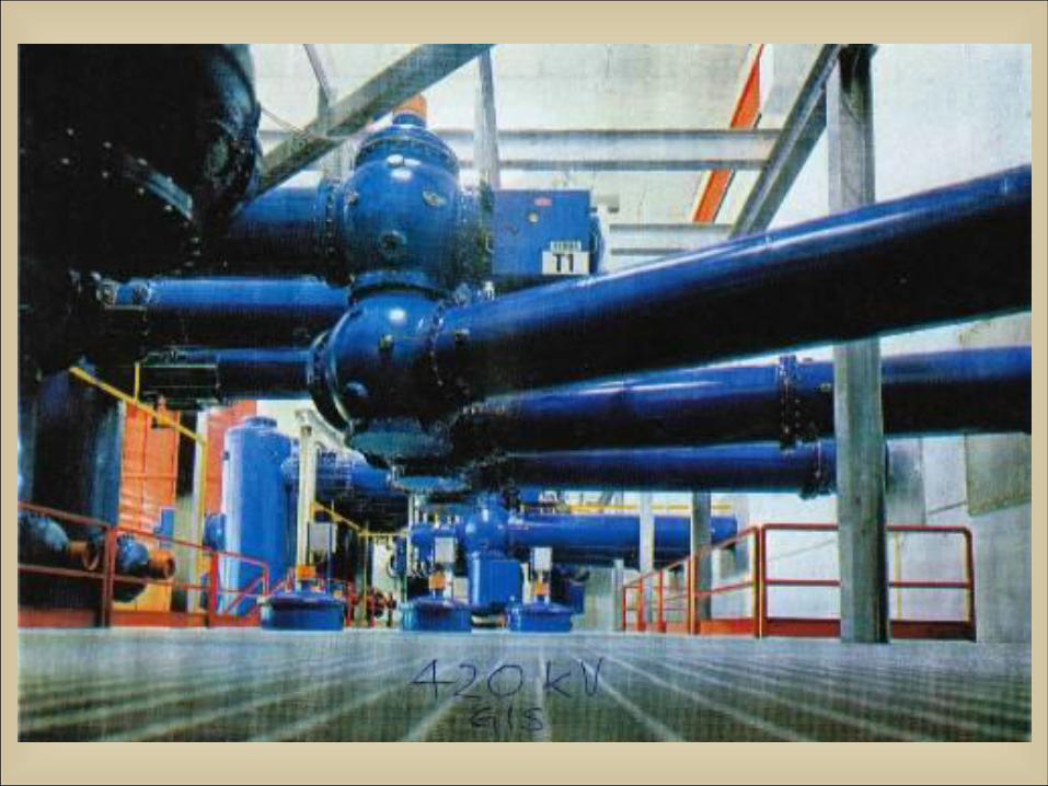
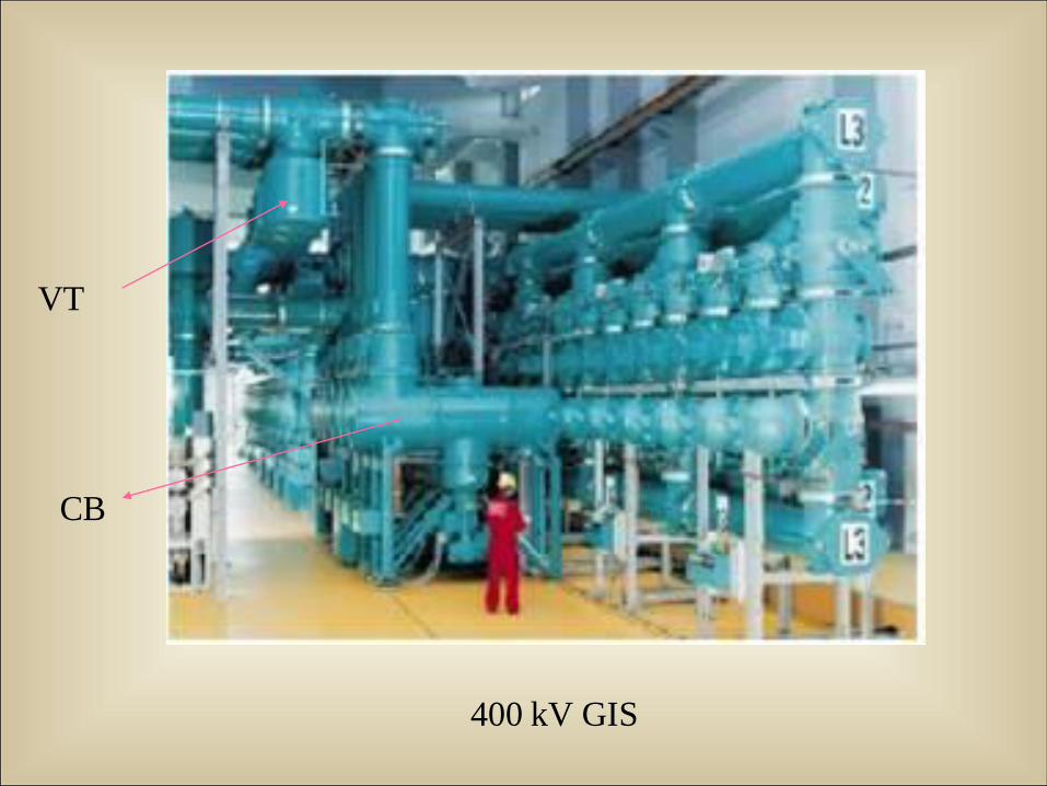
400 kV GIS
VT
CB
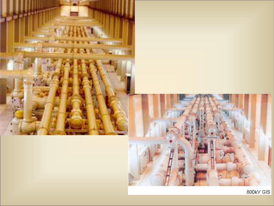
800 kV GIS

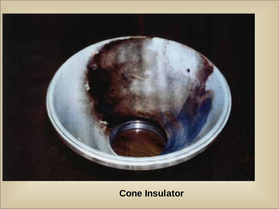
Cone Insulator
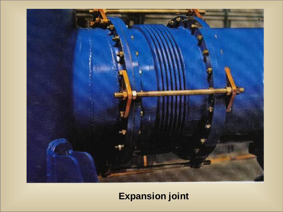
Expansion joint

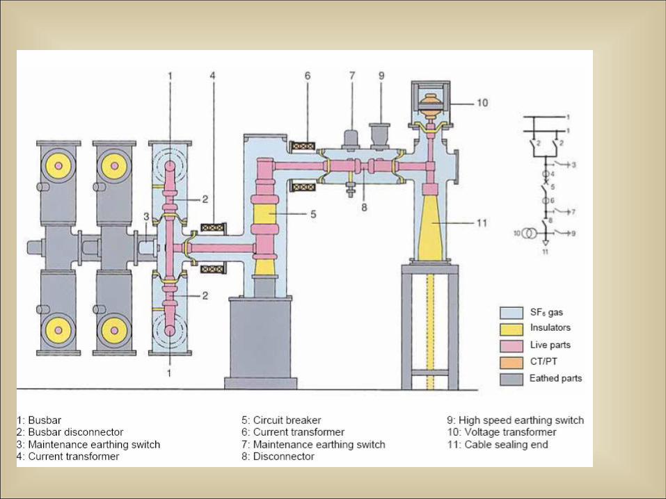
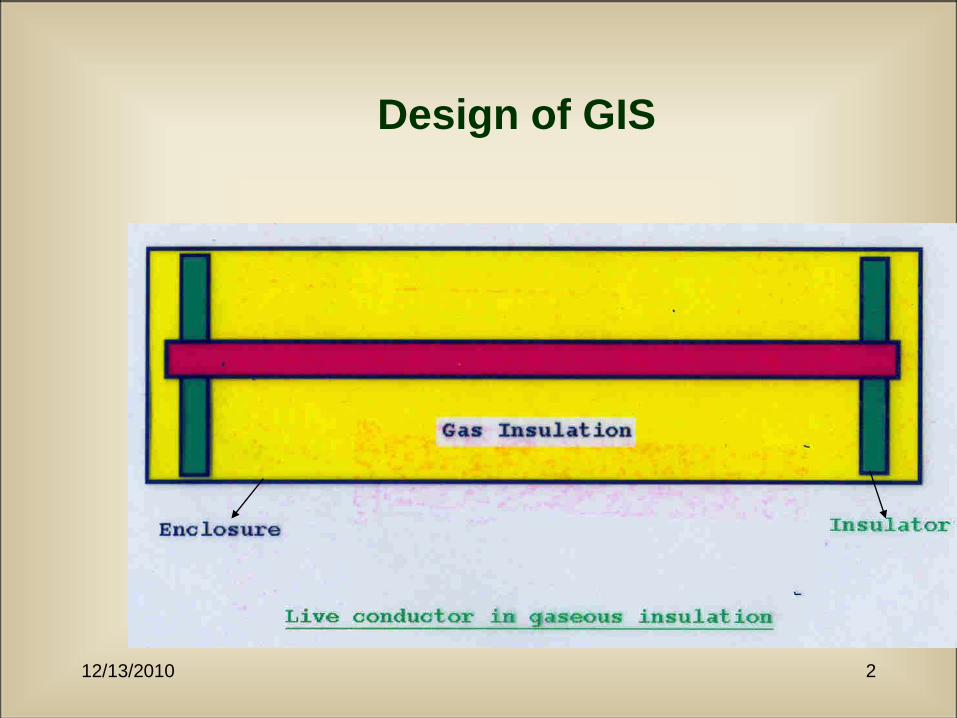
Concept of GIS
12/13/2010 2
Design of GIS
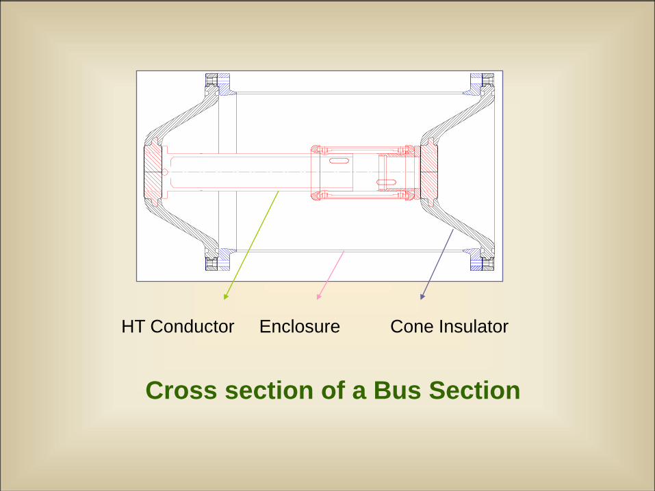
HT Conductor Enclosure Cone Insulator
Cross section of a Bus Section
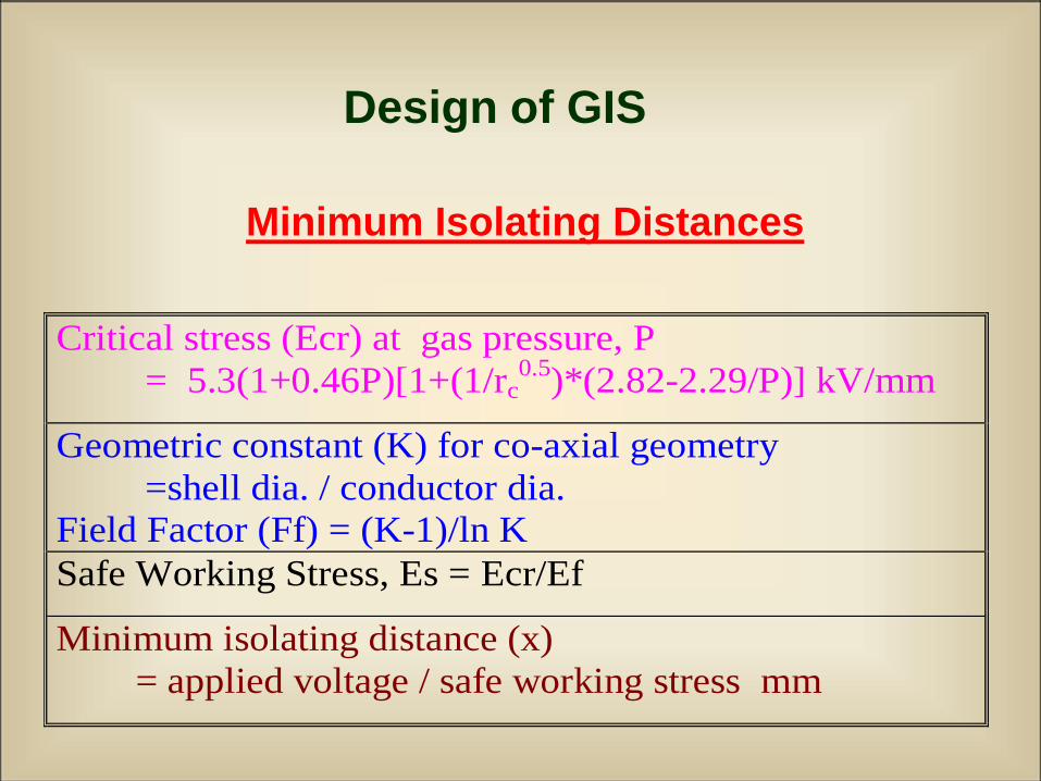
Design of GIS
Minimum Isolating Distances
Critical stress (Ecr) at gas pressure, P
= 5.3(1+0.46P)[1+(1/rc0.5
)*(2.82-2.29/P)] kV/mm
Geometric constant (K) for co-axial geometry
=shell dia. / conductor dia.
Field Factor (Ff) = (K-1)/ln K
Safe Working Stress, Es = Ecr/Ef
Minimum isolating distance (x)
= applied voltage / safe working stress mm
Design of GIS
The gas-insulated equipment works under two major
stresses:
1. Electrical stress
2. Mechanical stress
The electrical design results in basic clearances
between HT conductor and the enclosure. Controlling
of electrical stresses on high voltage electrodes is also
an objective of the electrical design.
The mechanical design comprising of equipment
dimensions, support structures and the operating
systems like drives for switching components.
12/13/2010 6
Design Philosophy
• Safety
• High reliability
12/13/2010 7
Safety
• Safety is introduced by optimising operating
electrical stresses to safe levels by better inter-
electrode spacing
• Safety is reinforced by increasing the gas
volume and the thermal inertia of the system to
enhance cooling and retain insulation strength
12/13/2010 8
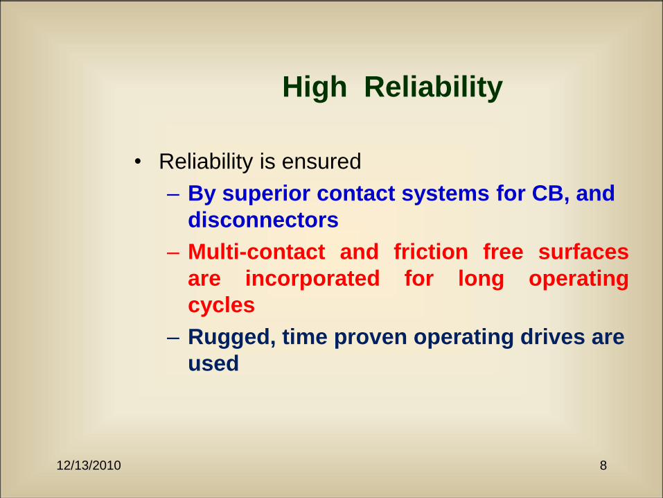
High Reliability
• Reliability is ensured
– By superior contact systems for CB, and
disconnectors
– Multi-contact and friction free surfaces
are incorporated for long operating
cycles
– Rugged, time proven operating drives are
used
12/13/2010 9
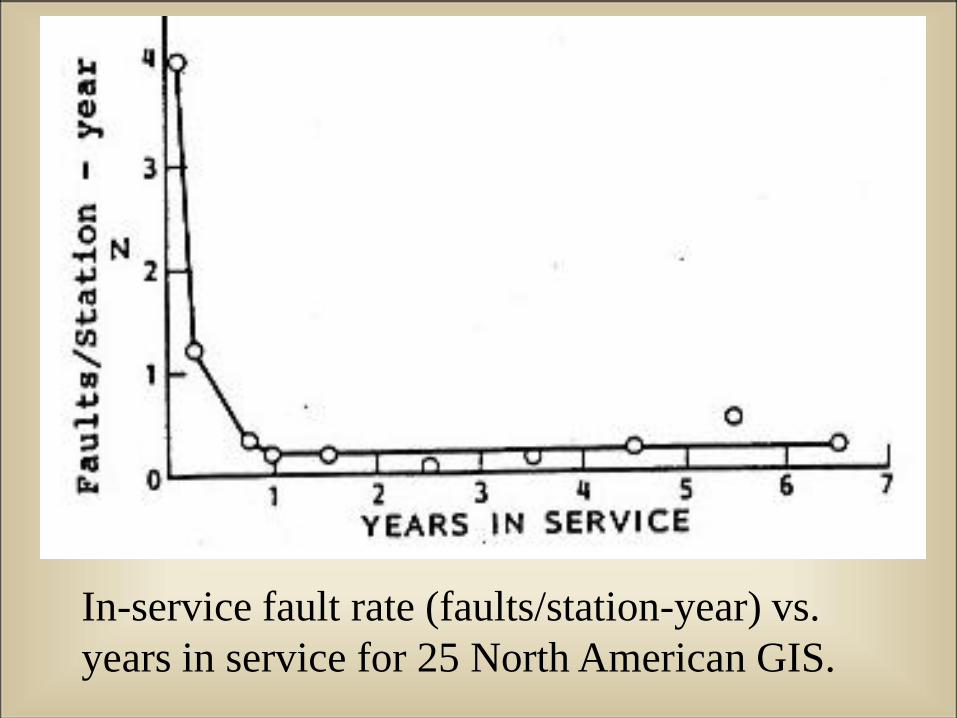
In-service fault rate (faults/station-year) vs.
years in service for 25 North American GIS.
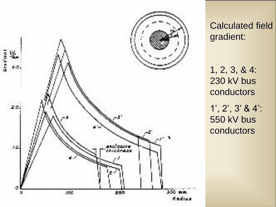
Calculated field
gradient:
1, 2, 3, & 4:
230 kV bus
conductors
1’, 2’, 3’ & 4’:
550 kV bus
conductors
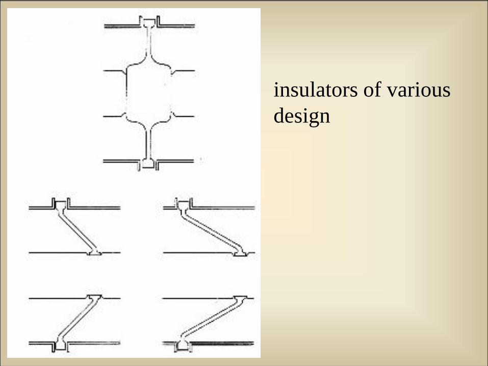
insulators of various
design
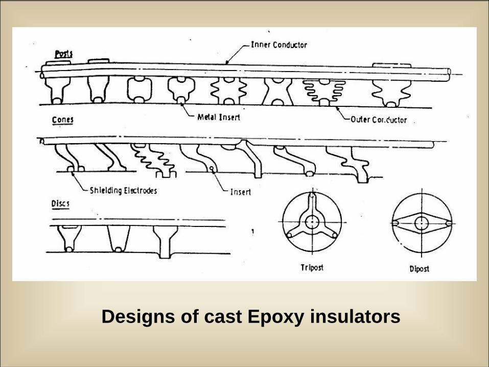
Designs of cast Epoxy insulators
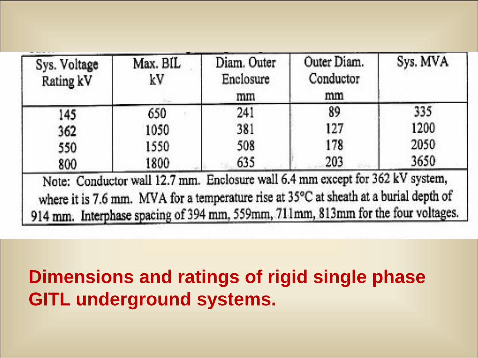
Dimensions and ratings of rigid single phase
GITL underground systems.
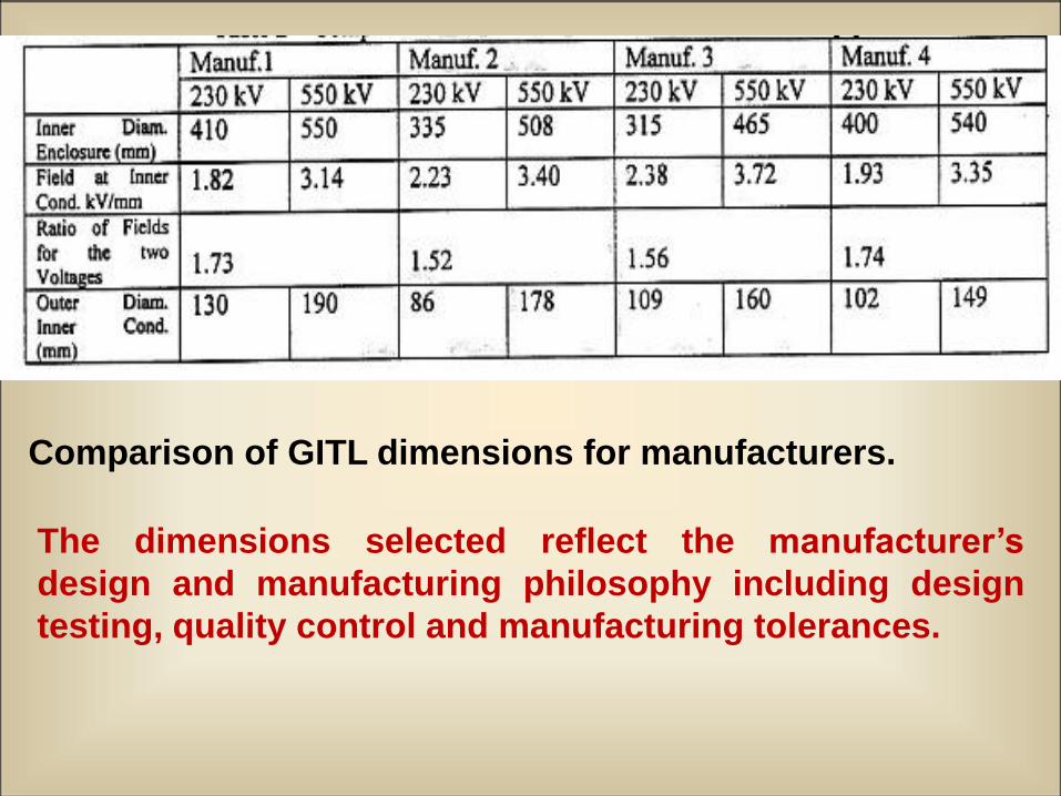
Comparison of GITL dimensions for manufacturers.
The dimensions selected reflect the manufacturer’s
design and manufacturing philosophy including design
testing, quality control and manufacturing tolerances.
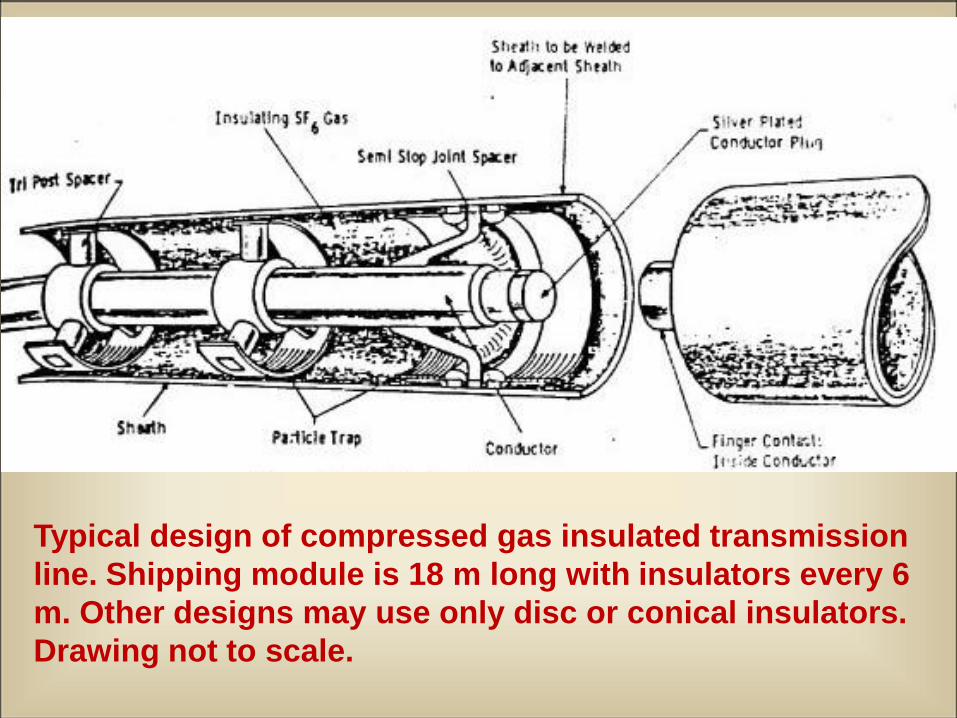
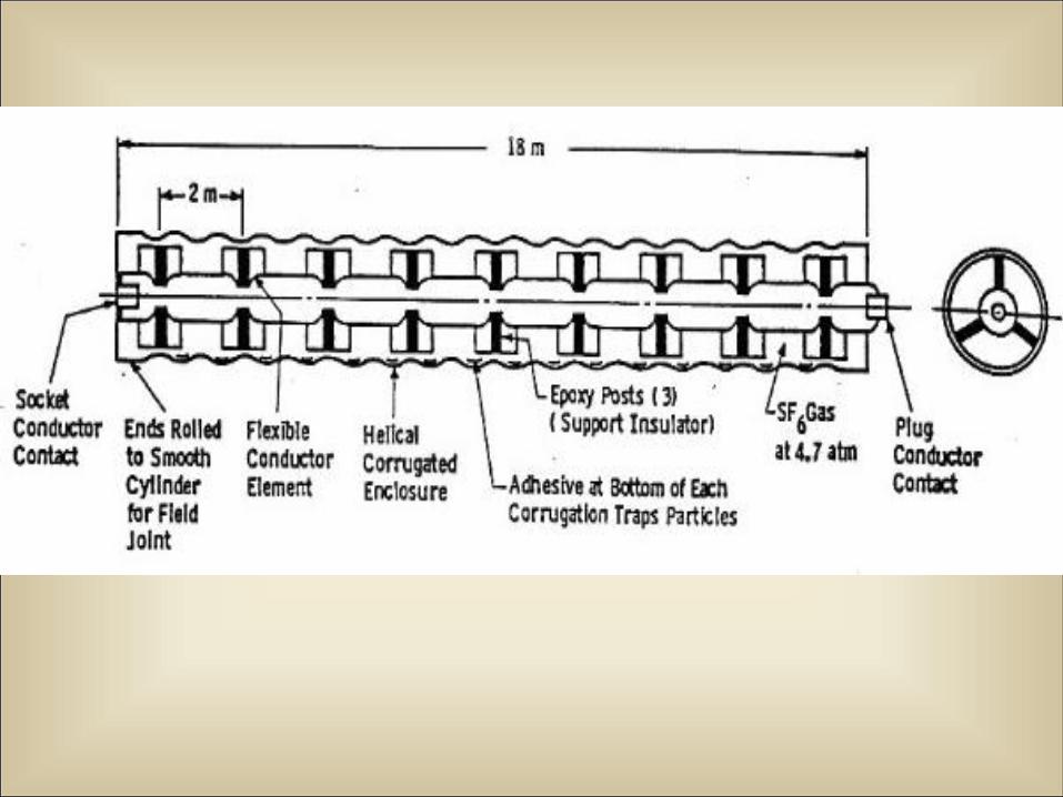
Typical design of compressed gas insulated transmission
line. Shipping module is 18 m long with insulators every 6
m. Other designs may use only disc or conical insulators.
Drawing not to scale.
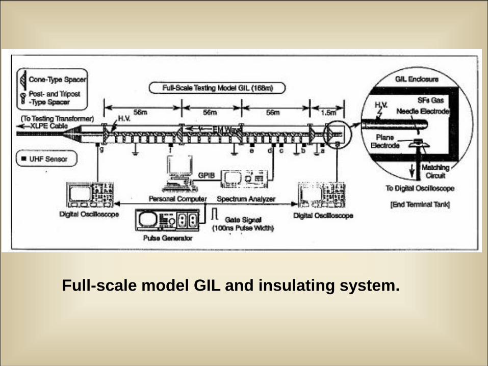
Full-scale model GIL and insulating system.
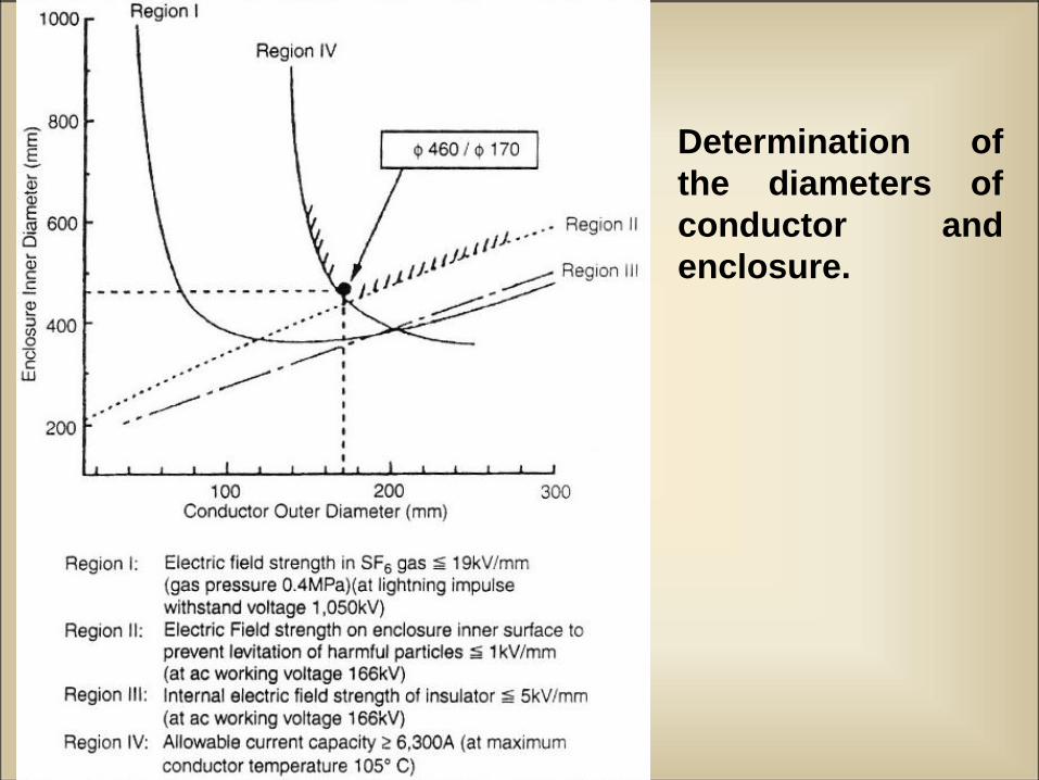
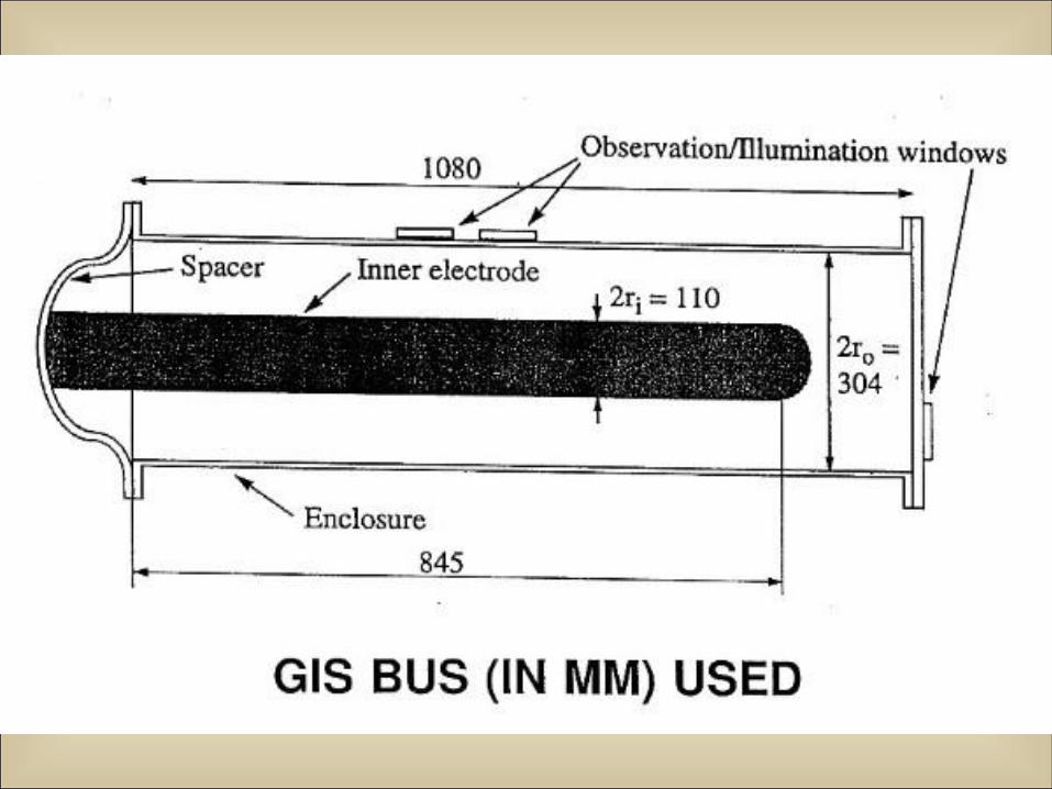
Determination of
the diameters of
conductor and
enclosure.
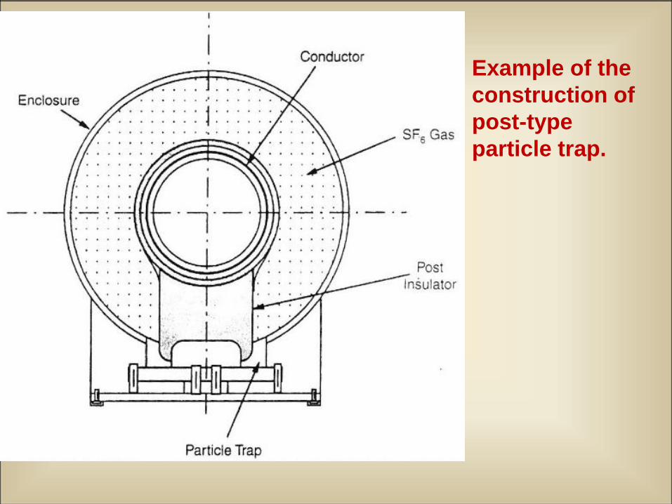
Example of the
construction of
post-type
particle trap.
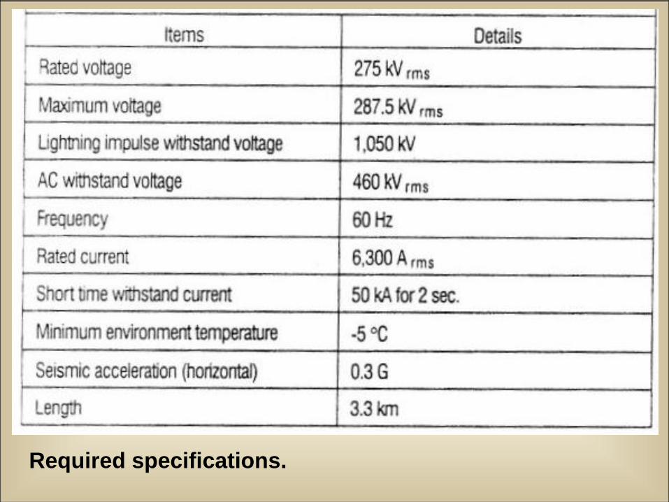
Required specifications.
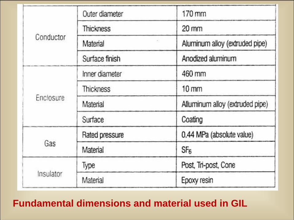
Fundamental dimensions and material used in GIL
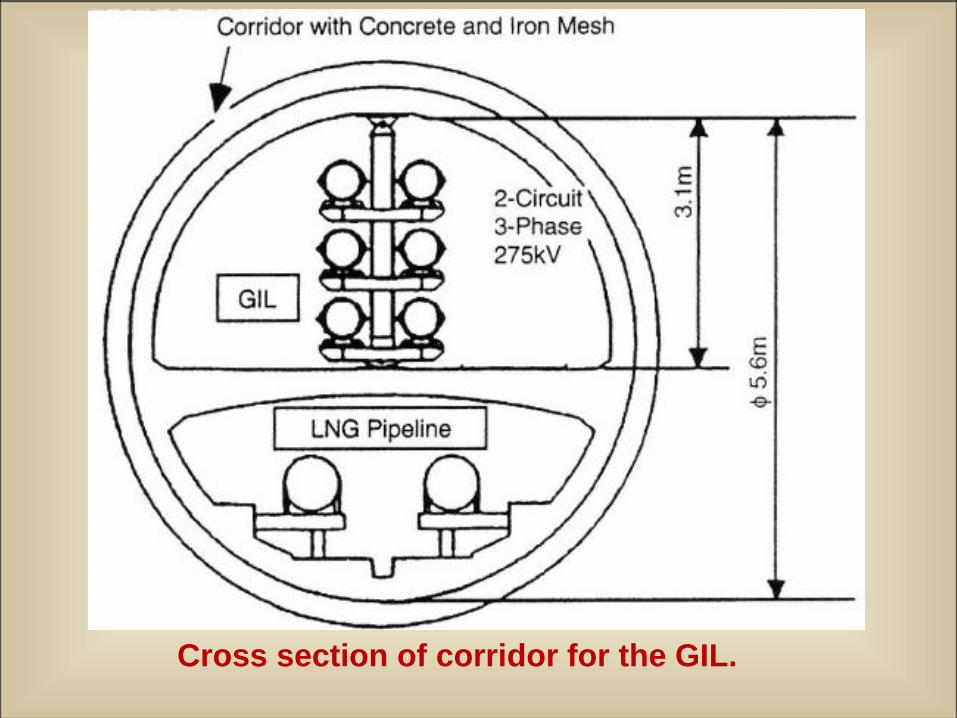
Cross section of corridor for the GIL.
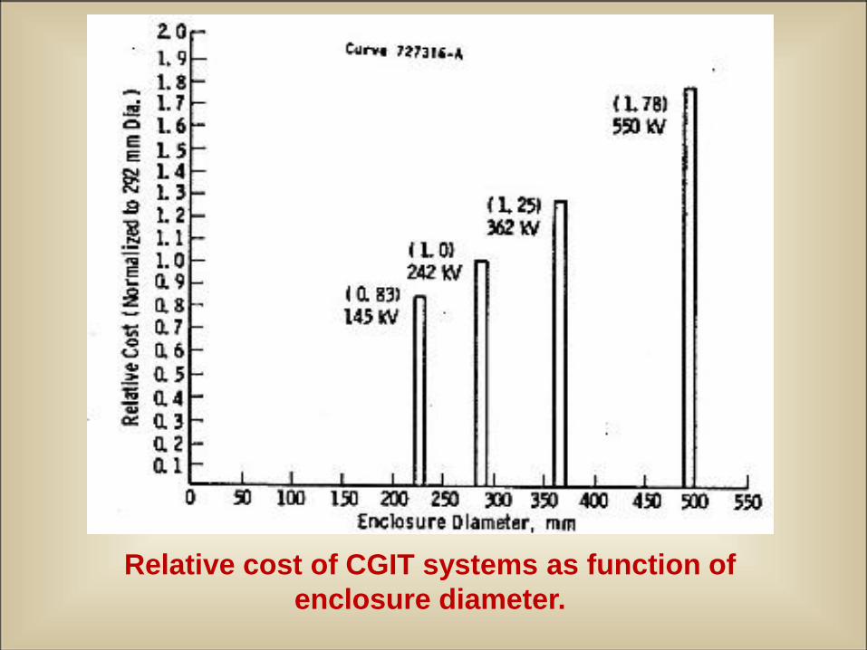
Relative cost of CGIT systems as function of
enclosure diameter.
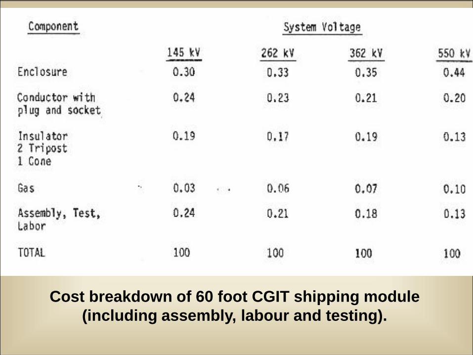
Cost breakdown of 60 foot CGIT shipping module
(including assembly, labour and testing).
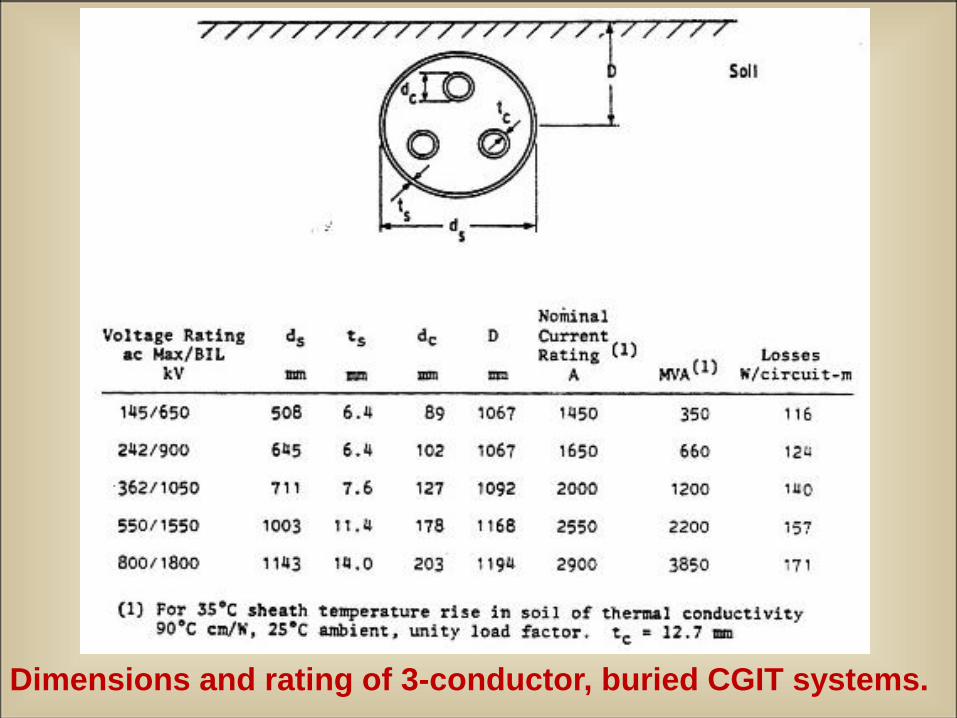
Dimensions and rating of 3-conductor, buried CGIT systems.
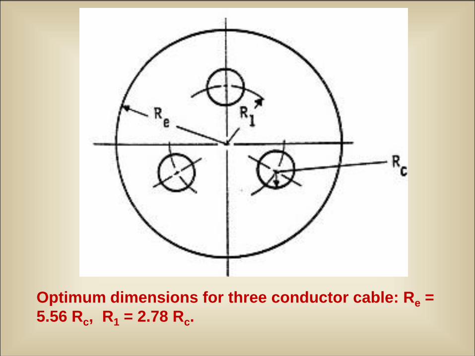
Optimum dimensions for three conductor cable: Re =
5.56 Rc, R1 = 2.78 Rc.
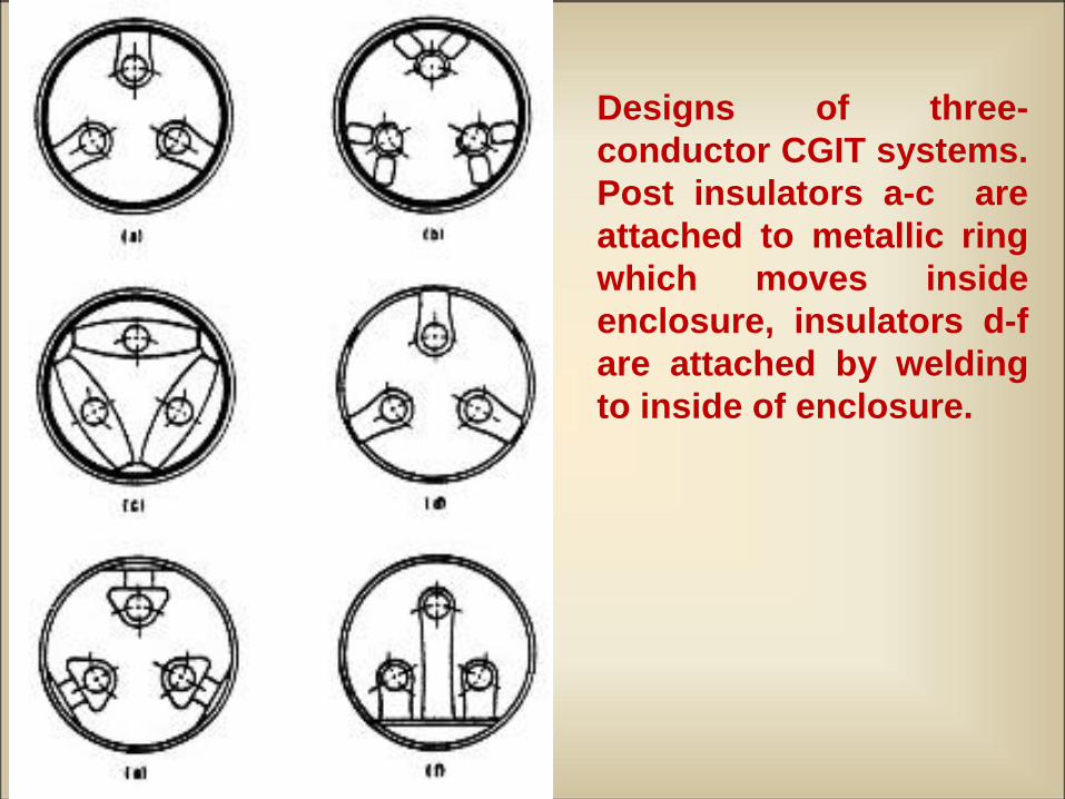
Designs of three-
conductor CGIT systems.
Post insulators a-c are
attached to metallic ring
which moves inside
enclosure, insulators d-f
are attached by welding
to inside of enclosure.
12/13/2010 29
Medium Voltage
Gas Insulated Substation Systems
12/13/2010 30
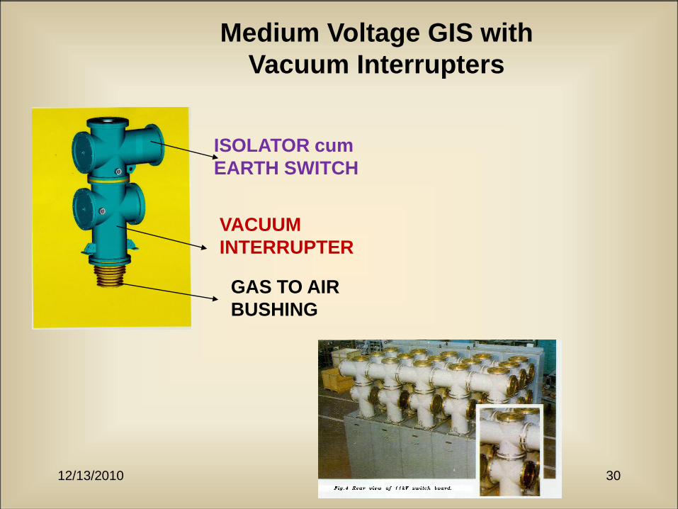
Medium Voltage GIS with
Vacuum Interrupters
ISOLATOR cum
EARTH SWITCH
VACUUM
INTERRUPTER
GAS TO AIR
BUSHING
12/13/2010 31
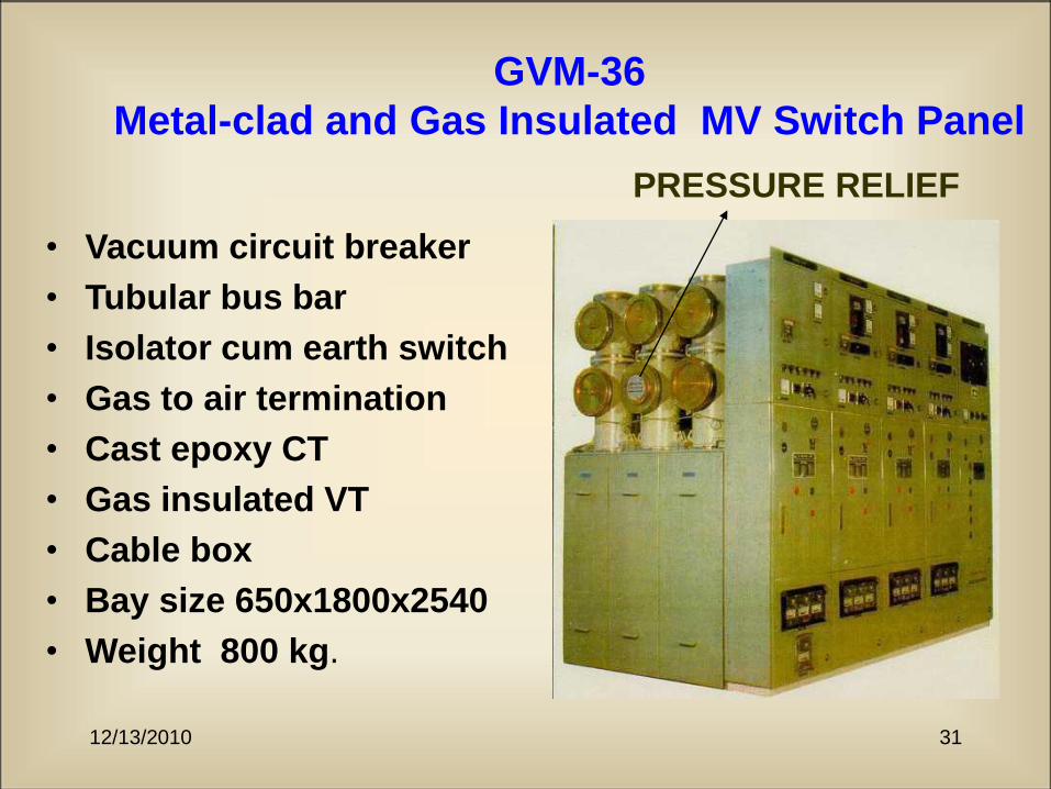
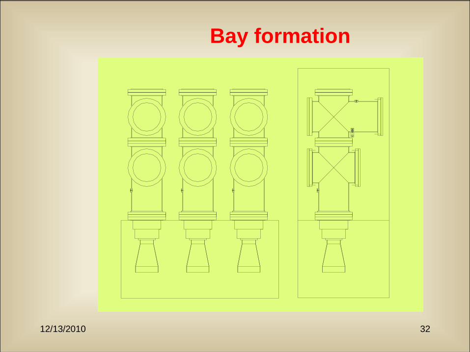
GVM-36
Metal-clad and Gas Insulated MV Switch Panel
• Vacuum circuit breaker
• Tubular bus bar
• Isolator cum earth switch
• Gas to air termination
• Cast epoxy CT
• Gas insulated VT
• Cable box
• Bay size 650x1800x2540
• Weight 800 kg.
PRESSURE RELIEF
12/13/2010 32
Bay formation
12/13/2010 33
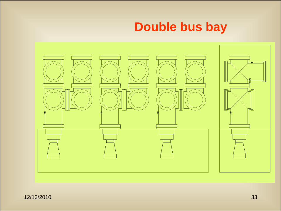
Double bus bay
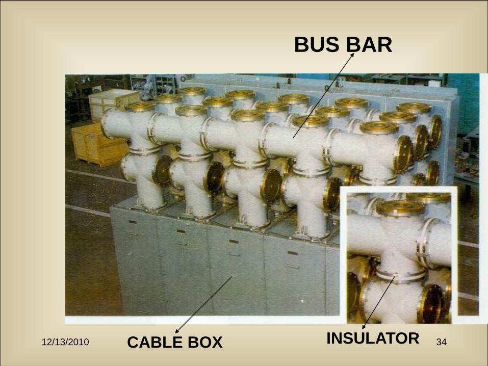
12/13/2010 34CABLE BOX
BUS BAR
INSULATOR
12/13/2010 35
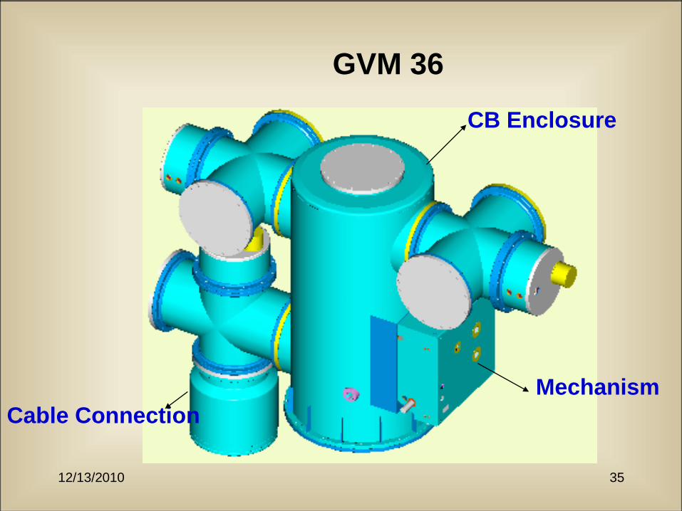
GVM 36
Mechanism
CB Enclosure
Cable Connection
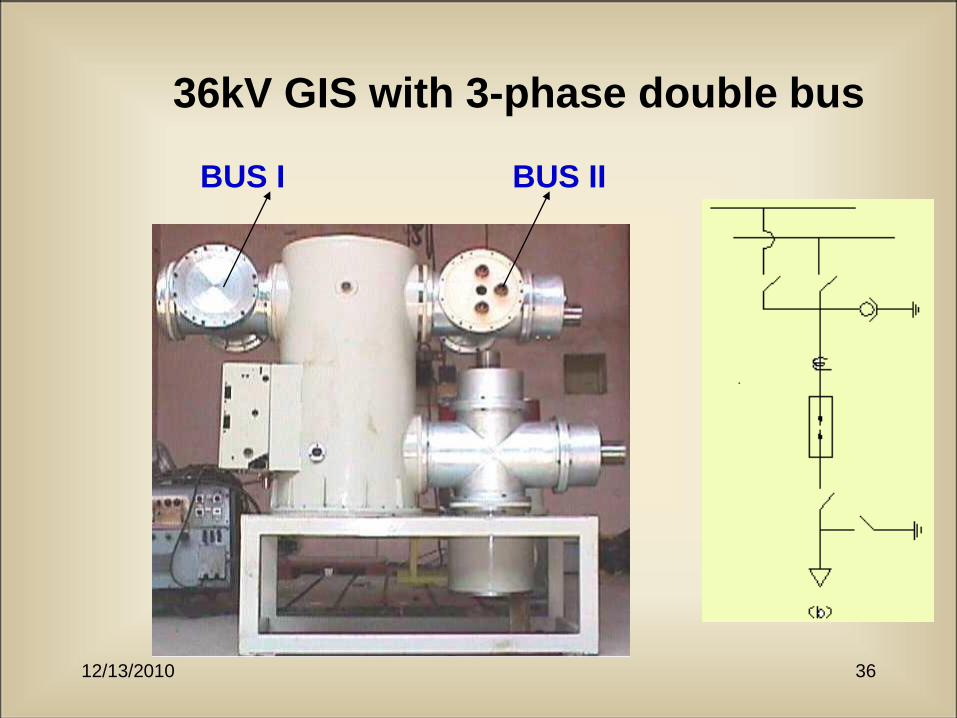
12/13/2010 36
36kV GIS with 3-phase double bus
BUS I BUS II
12/13/2010 37
High & Ultra High Voltage
Gas Insulated Equipment
and Systems

12/13/2010 38
GIS Bay
Single Line Diagram
12/13/2010 39
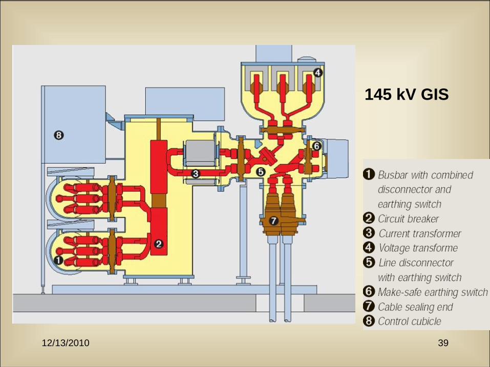
145 kV GIS
12/13/2010 40
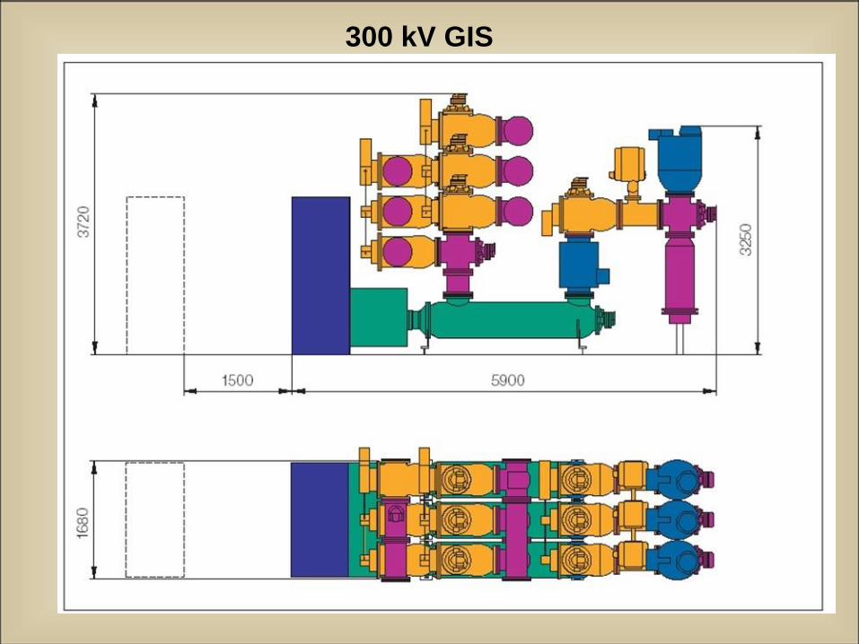
300 kV GIS
12/13/2010 41
12/13/2010 42
12/13/2010 43
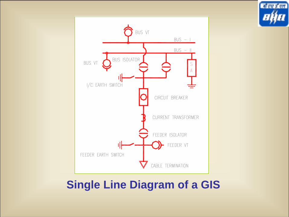
Single Line Diagram of a GIS
12/13/2010 45
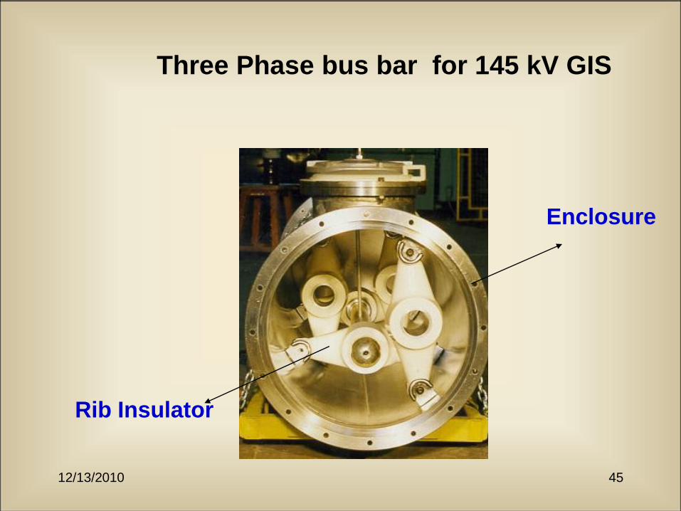
Three Phase bus bar for 145 kV GIS
Rib Insulator
Enclosure
12/13/2010 46

12/13/2010 47
Circuit Breaker under SC Test at CESI
Mechanism
Line side
Load side
Housing
12/13/2010 48
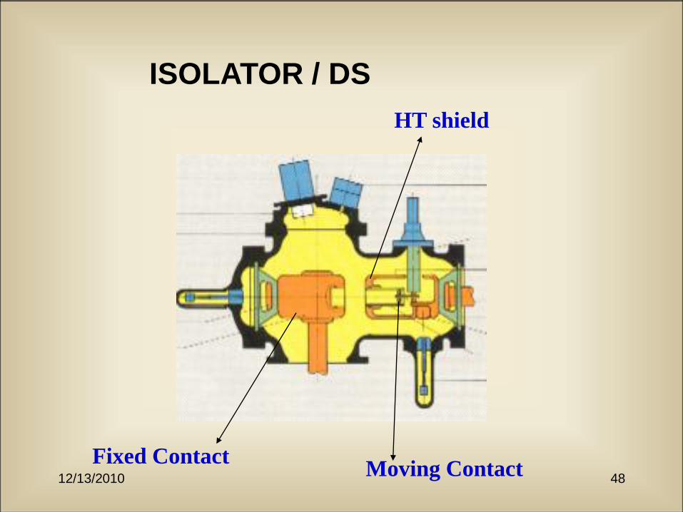
ISOLATOR / DS
Fixed ContactMoving Contact
HT shield

12/13/2010 49
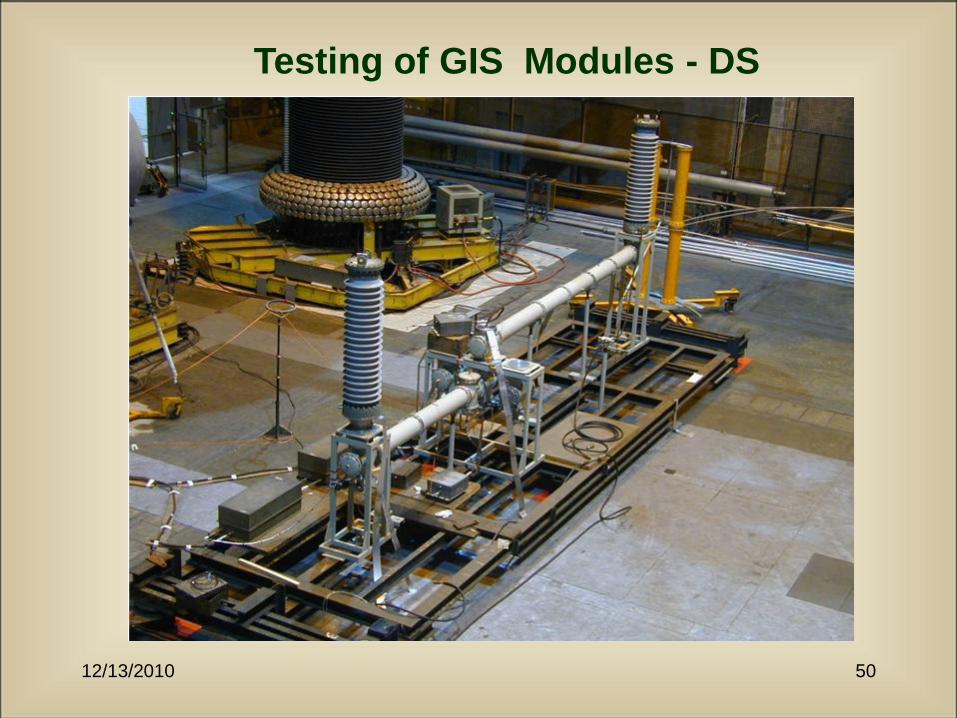
Testing of GIS Modules - DS
• Bus Charging current: The current in rms value which
breaker shall make or break when energising or de-
energizing parts of a bus bar system.
• TD1 : Switching of a very short portion of bus duct.
• AC Voltage: 1.1xVph DC Voltage: -1.1*1.414*Vph
• Bus Transfer Current : This is the current disconnector
shall make or breaks when the disconnector transfers
load from one bus system to another.
• The current is 80% of the current rating or maximum
limited to 1600 A.
12/13/2010 50
Testing of GIS Modules - DS
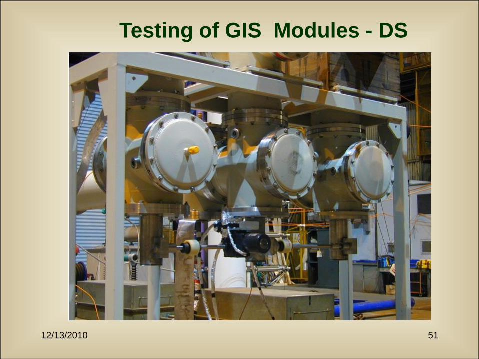
12/13/2010 51
Testing of GIS Modules - DS
12/13/2010 52
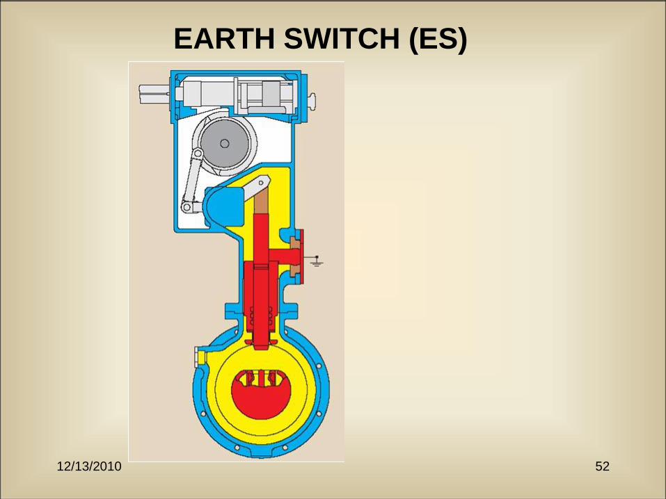
EARTH SWITCH (ES)
12/13/2010 53
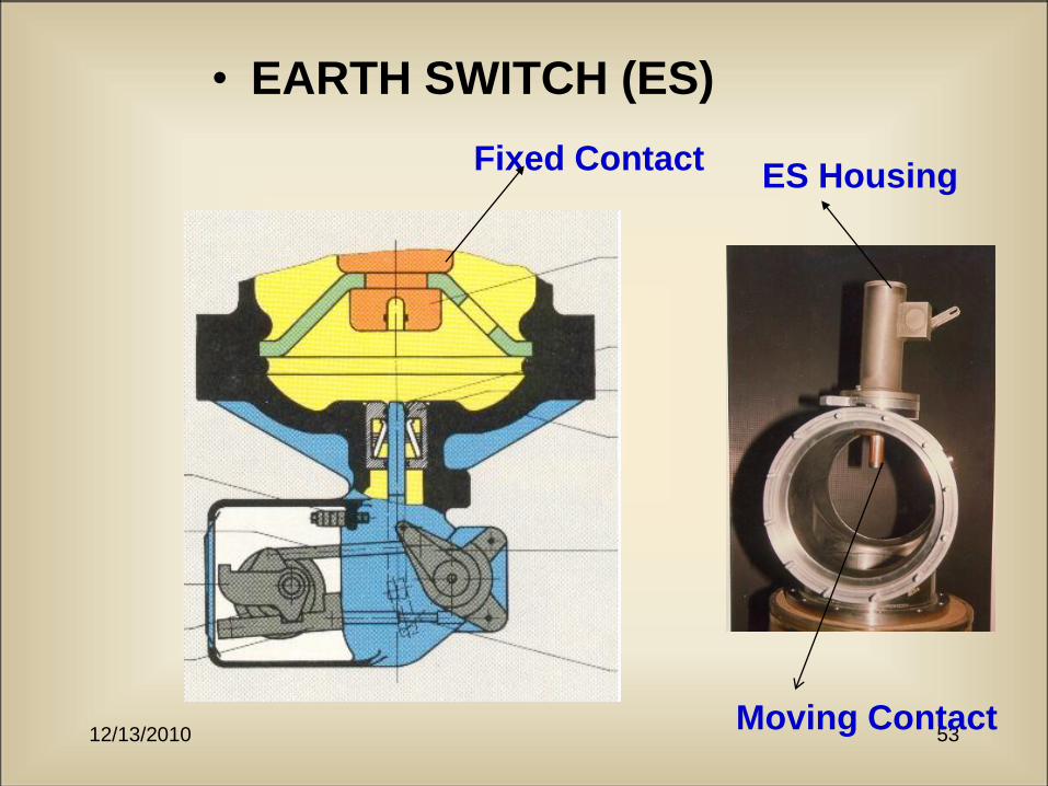
• EARTH SWITCH (ES)
Fixed Contact
Moving Contact
ES Housing

12/13/2010 54
Design and development of 145 kV,
40 kA Gas Insulated Earth Switch.
The earth switch developed in
the present contribution can
be used to discharge long
lines/cables basically for
removal of DC voltage /
trapped voltage on the line.
The switch can also be used
to discharge the HT line
before opted for maintenance
of the substation.

12/13/2010 55
Testing of GIS modules -
Earth Switch
• 2 No. of Making operations.
• Verification of per-arc characteristic with-
out s/c current.
• Electromagnetic current 50 A @ 1k V.
• Electrostatic Current 0.4 A @ 3 kV.
• 10 No. make/break operating cycles.

12/13/2010 56
12/13/201057
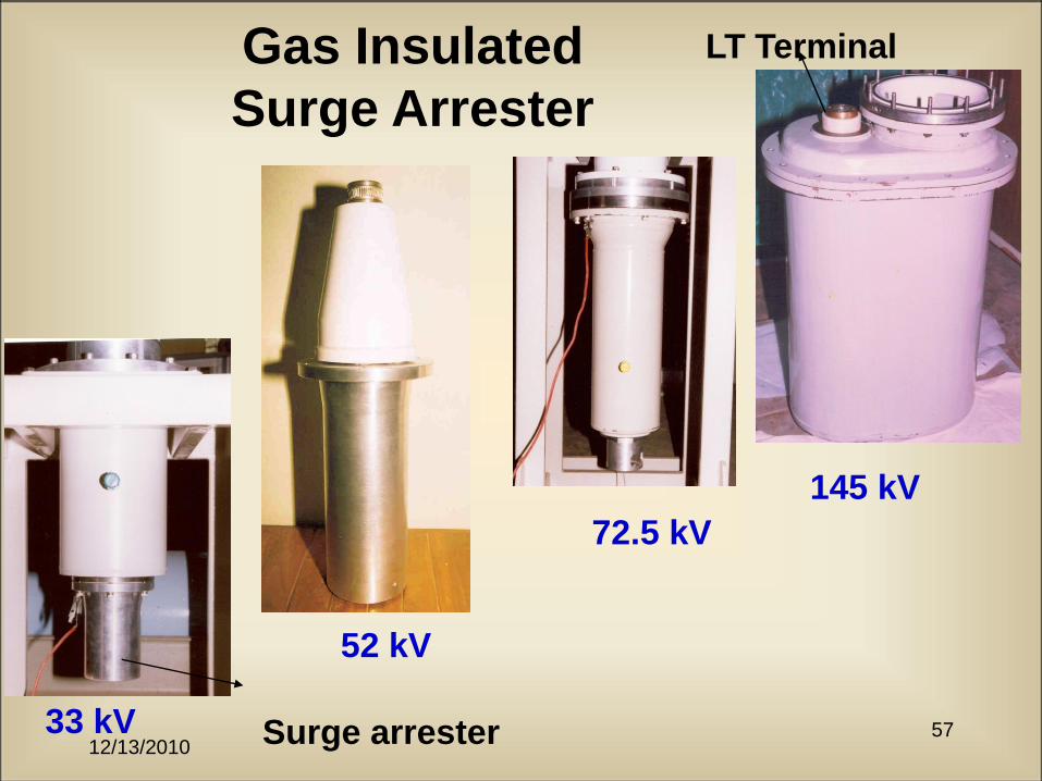
Gas Insulated
Surge Arrester
33 kV
72.5 kV
145 kV
LT Terminal
52 kV
Surge arrester
12/13/2010 58
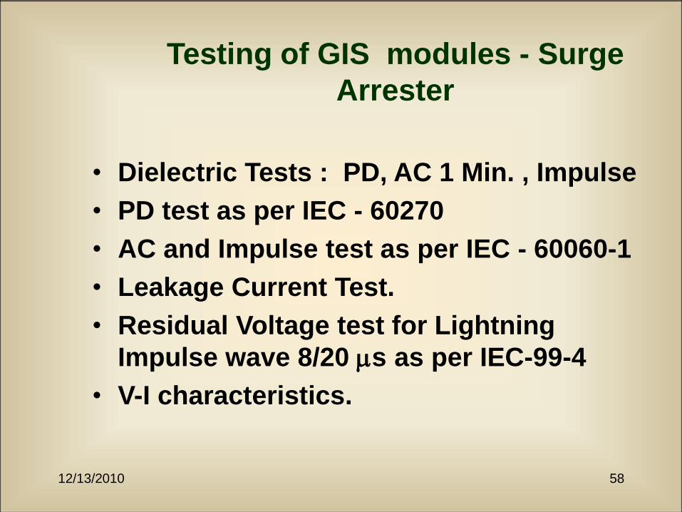
Testing of GIS modules - Surge
Arrester
• Dielectric Tests : PD, AC 1 Min. , Impulse
• PD test as per IEC - 60270
• AC and Impulse test as per IEC - 60060-1
• Leakage Current Test.
• Residual Voltage test for Lightning
Impulse wave 8/20 s as per IEC-99-4
• V-I characteristics.

12/13/2010 59
Testing of GIS modules - Surge
Arrester
12/13/2010 60
Technological Advancements
• Fast response surge arresters
– A break-through in SA technology
– Patented arrangement of MOV elements help
reducing the inductance of the system.
– Uniform voltage distribution on elements
(~3-6%)
12/13/2010 61
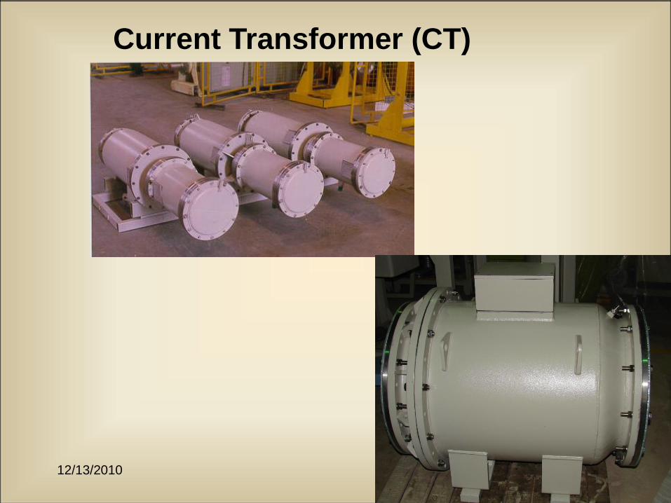
Current Transformer (CT)
12/13/2010 62
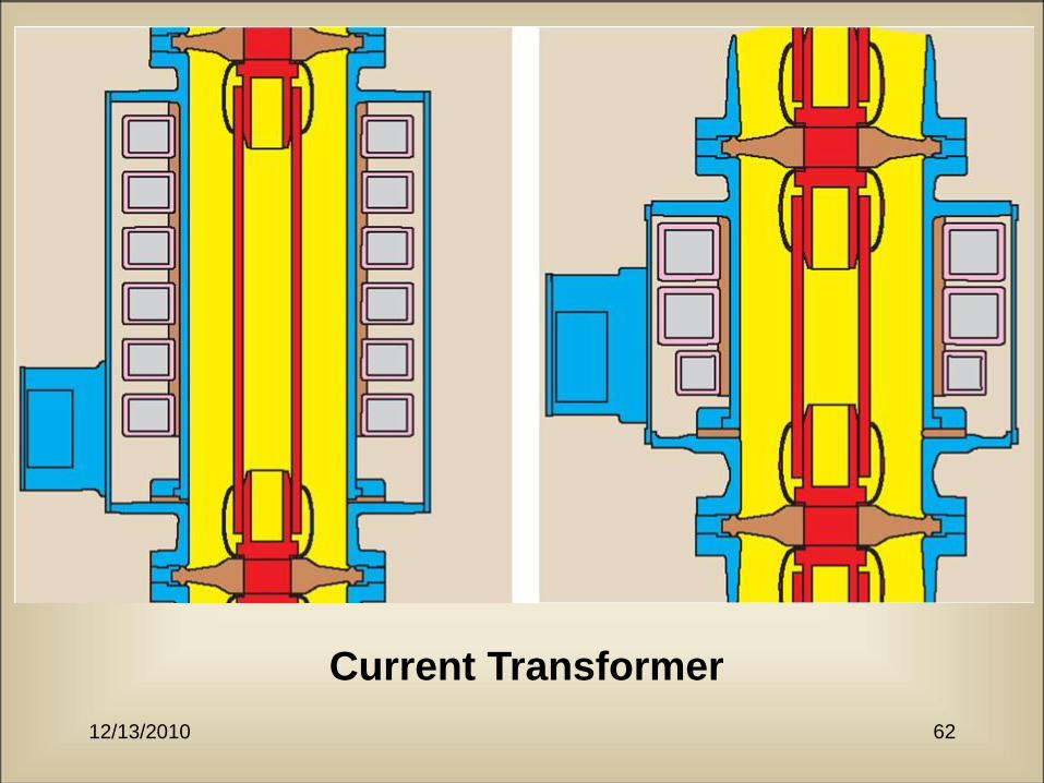
Current Transformer
12/13/2010 63
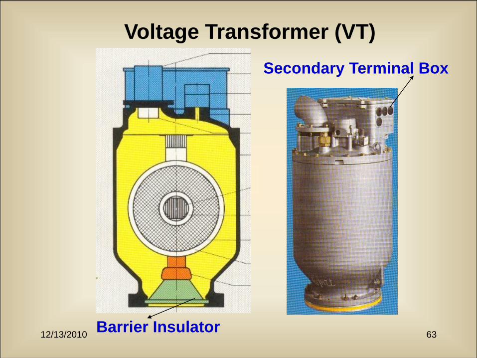
Voltage Transformer (VT)
Secondary Terminal Box
Barrier Insulator

12/13/2010 64
Cable-to-gas termination
Barrier Insulator
Silicon Rubber
BootXLPE
12/13/2010 65
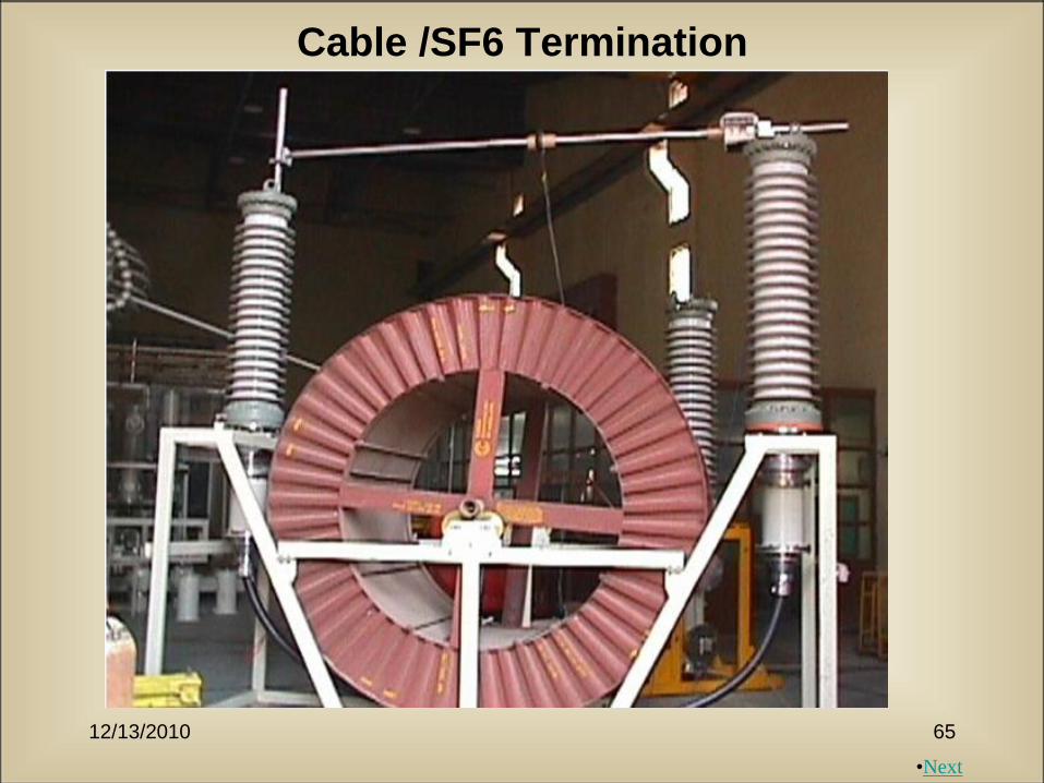
Cable /SF6 Termination
•Next

12/13/2010 66
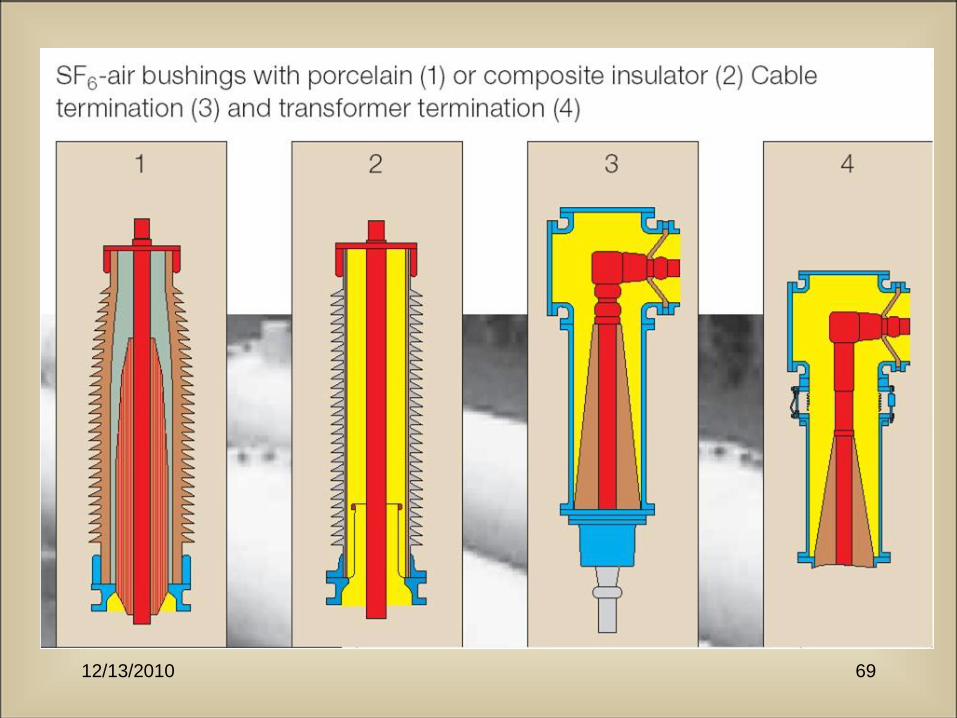
GAS-TO-AIR BUSHING

12/13/2010 67
Design and Development of Gas-to-Oil
Bushings 72.5 kV for GIS Application
The developed bushing
has been tested
successfully for an
insulation withstand
level suitable to 72.5
and 110 kV GIS. The
equipment has been
withstood at 40 kA for
the time duration of 1
sec with peak current
magnitude of 100 kA.
The development is first
of its kind in India.
12/13/2010 68
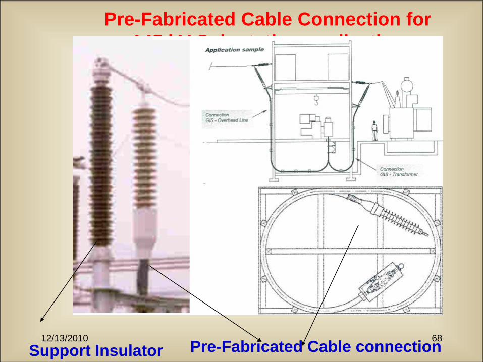
Pre-Fabricated Cable Connection for
145 kV Sub-station application
Support Insulator Pre-Fabricated Cable connection
12/13/2010 69
12/13/2010 70
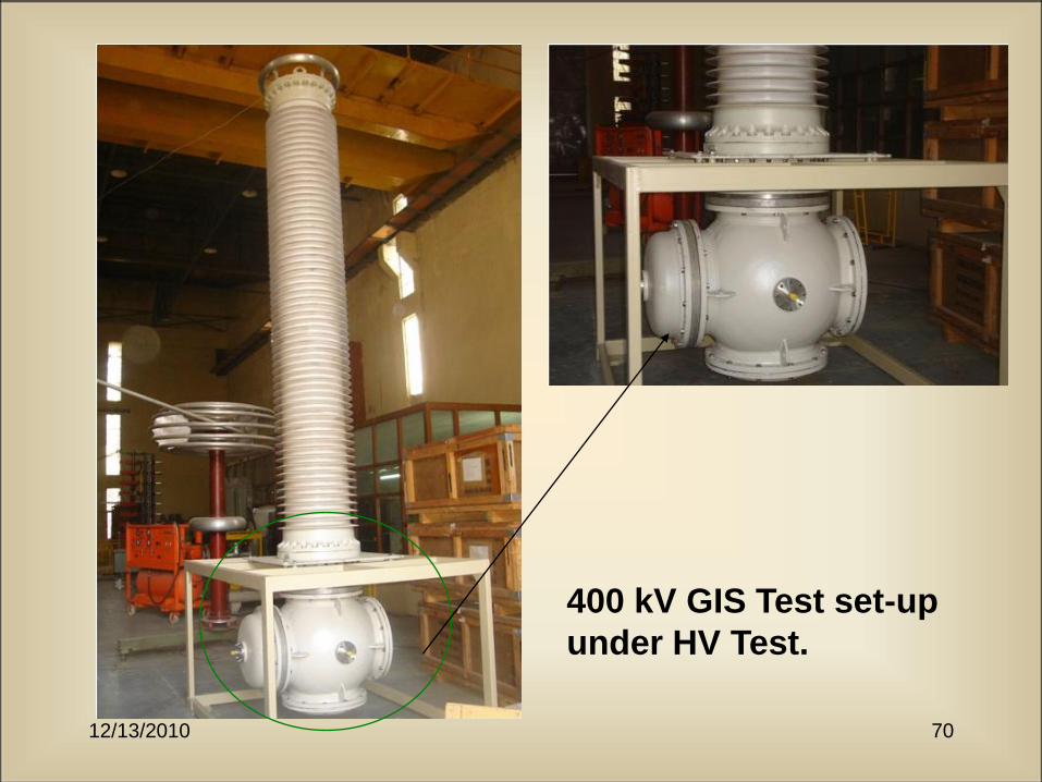
400 kV GIS Test set-up
under HV Test.
12/13/2010 71
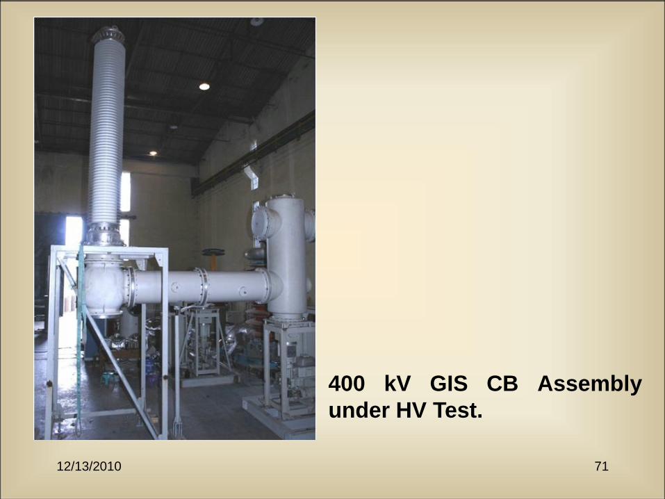
400 kV GIS CB Assembly
under HV Test.
12/13/2010 72
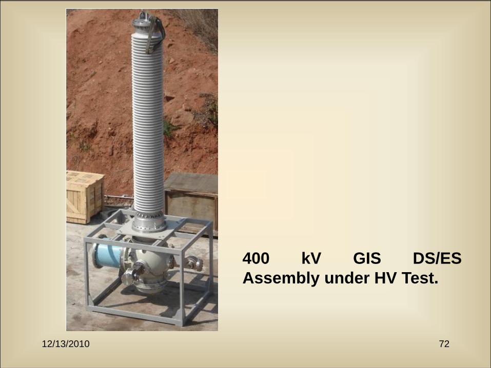
400 kV GIS DS/ES
Assembly under HV Test.
12/13/2010 73
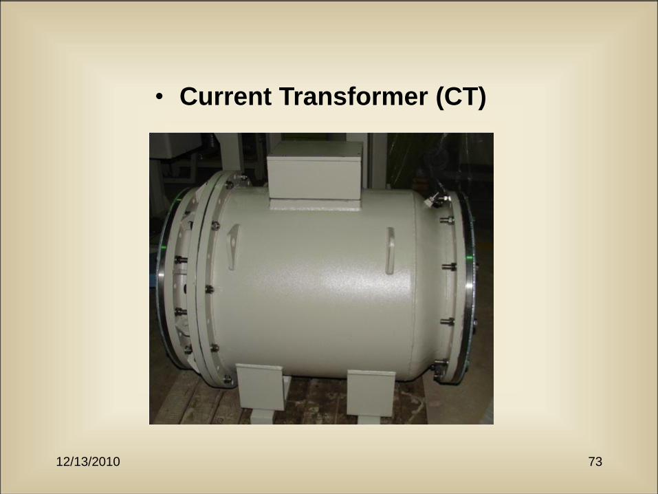
• Current Transformer (CT)
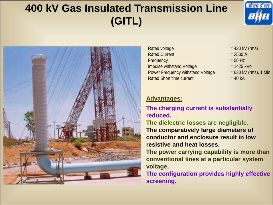
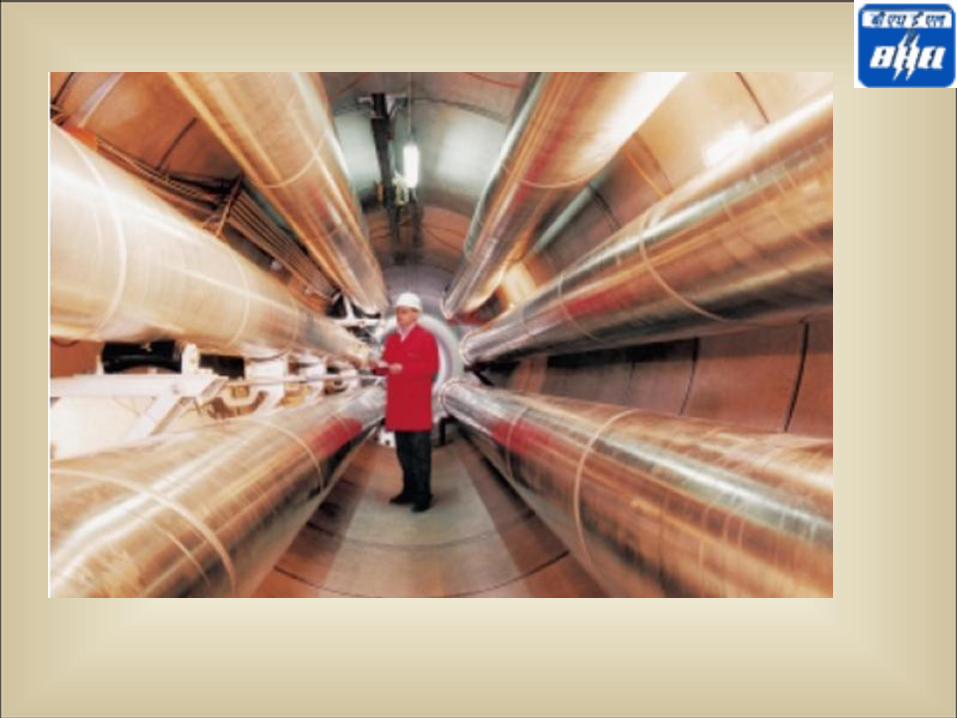
400 kV Gas Insulated Transmission Line
(GITL)
Rated voltage = 420 kV (rms)
Rated Current = 2500 A
Frequency = 50 Hz
Impulse withstand Voltage = 1425 kVp
Power Frequency withstand Voltage = 630 kV (rms), 1 Min.
Rated Short time current = 40 kA
Advantages:
The charging current is substantially
reduced.
The dielectric losses are negligible.
The comparatively large diameters of
conductor and enclosure result in low
resistive and heat losses.
The power carrying capability is more than
conventional lines at a particular system
voltage.
The configuration provides highly effective
screening.
12/13/2010 76
TEST FACILITIES
12/13/2010 77
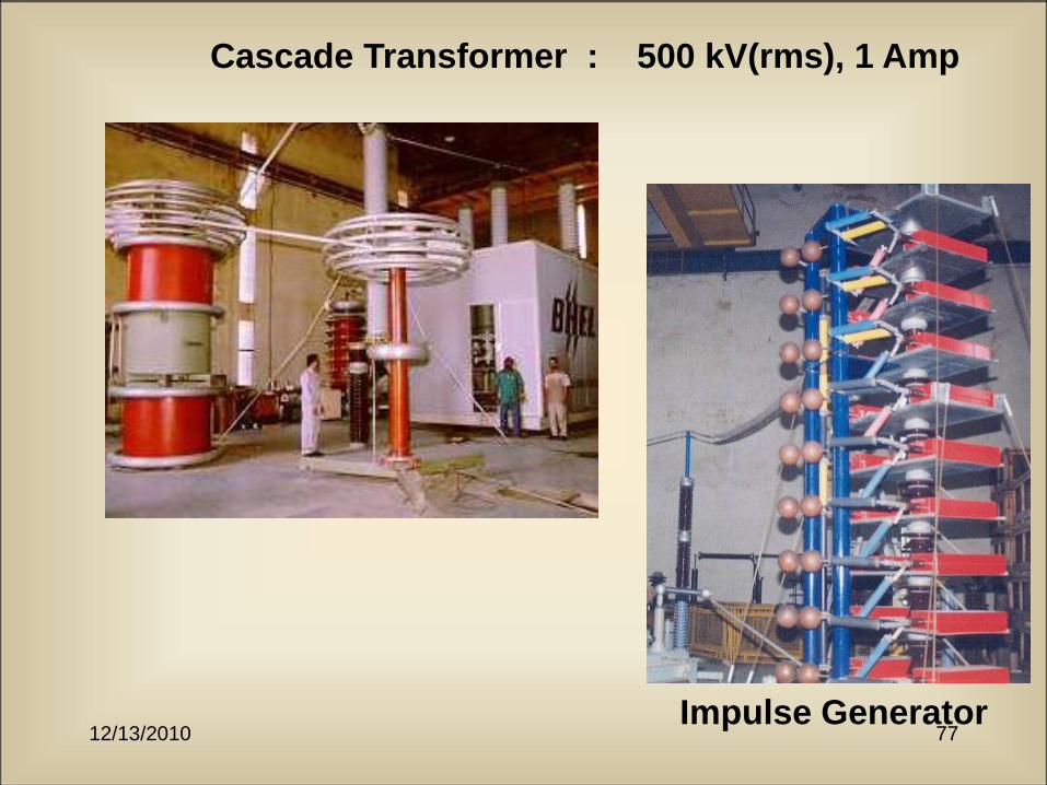
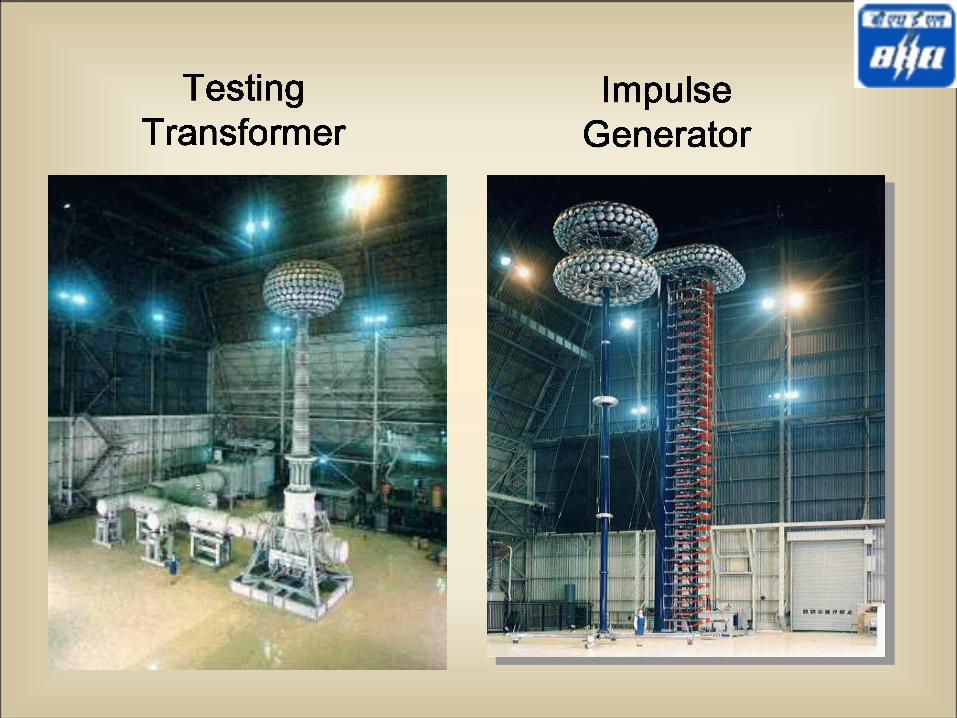
Cascade Transformer : 500 kV(rms), 1 Amp
Impulse Generator
12/13/2010 78
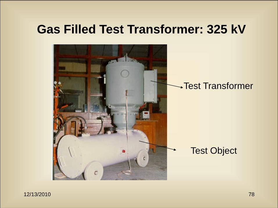
Gas Filled Test Transformer: 325 kV
Test Transformer
Test Object
12/13/2010 79
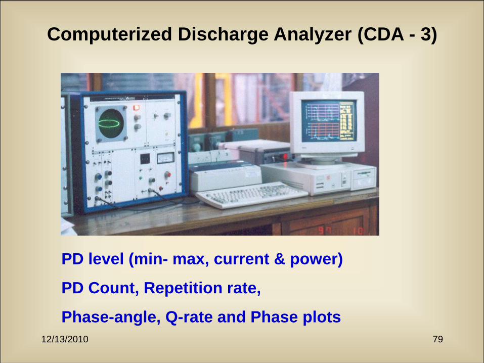
Computerized Discharge Analyzer (CDA - 3)
PD level (min- max, current & power)
PD Count, Repetition rate,
Phase-angle, Q-rate and Phase plots
12/13/2010 80
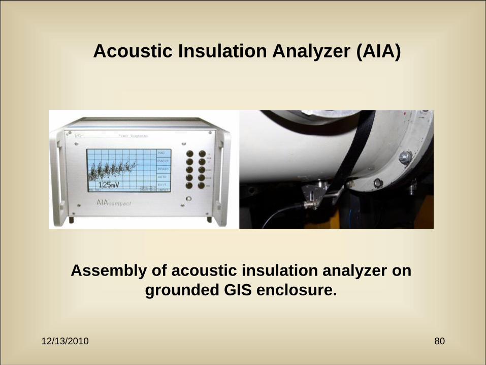
Acoustic Insulation Analyzer (AIA)
Assembly of acoustic insulation analyzer on
grounded GIS enclosure.
12/13/2010 82
Proof tests on GIS Enclosure
12/13/2010 83
Proof test on GIS Enclosure
• Gas insulated modules with welded steel
enclosures tested for 2.3 x normal pressure.
• Record of strain.
• No distortion in shape of enclosure.
12/13/2010 84
Arc Fault tests on GIS Enclosure
12/13/2010 85
Arc Fault test on GIS Enclosure
• Arc fault test at STC rating on GIS enclosure as per
IEC-62271-203.
• Arc fault test at 0.1 sec and 0.3 sec for 40 kA
and above.
• Arc fault test at 0.2 sec and 0.5 sec for 40 kA
below.
• Operation of pressure relief in first stage of
protection.
• No-fragmentation in second stage of protection.
12/13/2010 86
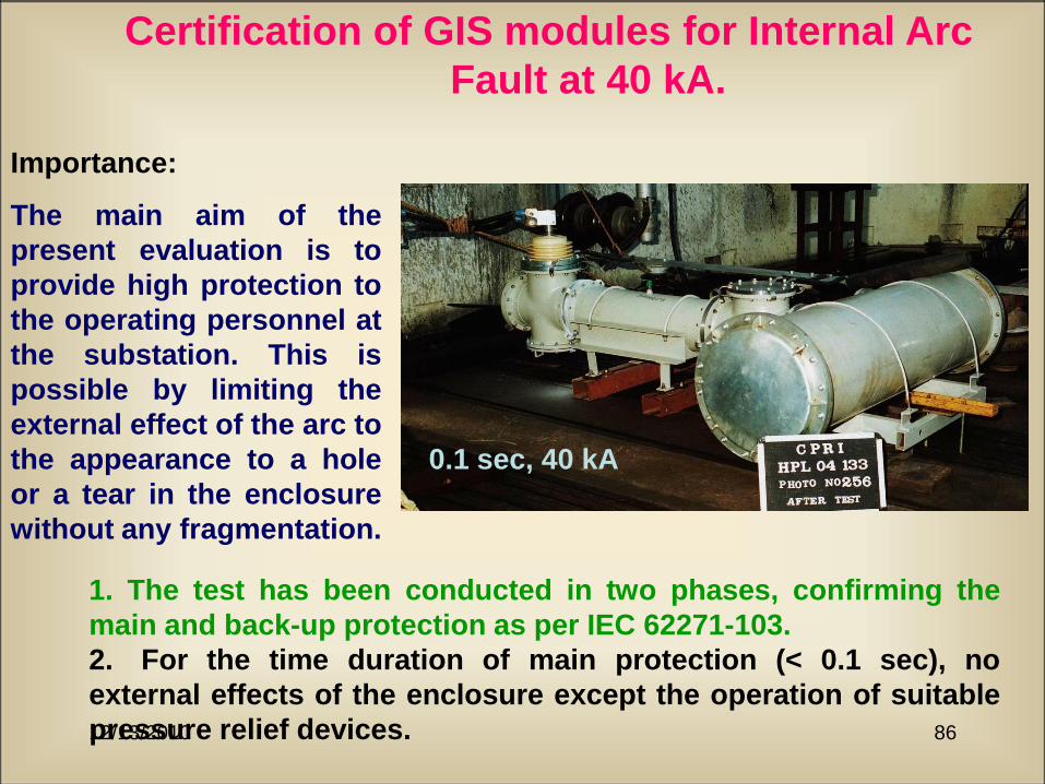
Certification of GIS modules for Internal Arc
Fault at 40 kA.
1. The test has been conducted in two phases, confirming the
main and back-up protection as per IEC 62271-103.
2. For the time duration of main protection (< 0.1 sec), no
external effects of the enclosure except the operation of suitable
pressure relief devices.
Importance:
The main aim of the
present evaluation is to
provide high protection to
the operating personnel at
the substation. This is
possible by limiting the
external effect of the arc to
the appearance to a hole
or a tear in the enclosure
without any fragmentation.
0.1 sec, 40 kA
12/13/2010 87
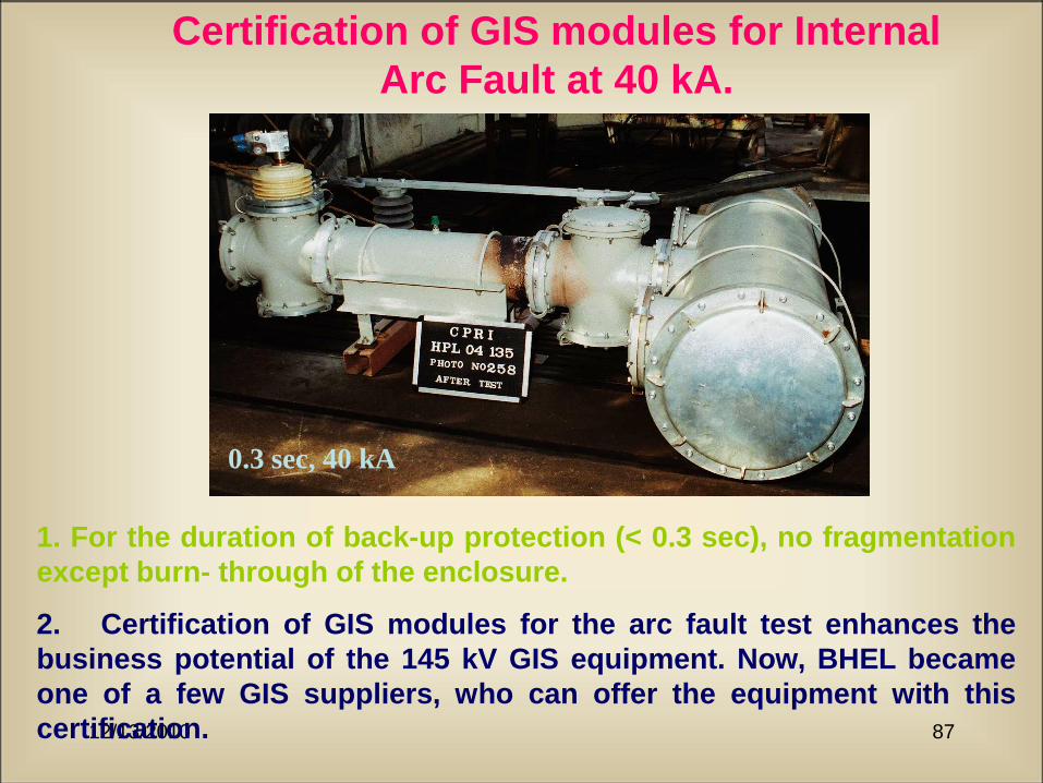
Certification of GIS modules for Internal
Arc Fault at 40 kA.
1. For the duration of back-up protection (< 0.3 sec), no fragmentation
except burn- through of the enclosure.
2. Certification of GIS modules for the arc fault test enhances the
business potential of the 145 kV GIS equipment. Now, BHEL became
one of a few GIS suppliers, who can offer the equipment with this
certification.
0.3 sec, 40 kA
12/13/2010 88
Site Testing of GIS
12/13/2010 89
Site Testing as per IEC-
60517
• Power Frequency test at 80 % of test voltage level for 1
min or impulse test at 80 % level.
• Power frequency test at 100 % of test voltage level for 1
min across isolator contacts or impulse test at 100 %
level.
• For 245 kV and above PD test as per standards IEC-
60270 : Conventional, VHF/UHF, Acoustic methods.
• AC and Impulse test as per IEC - 60060-1.
12/13/2010 90
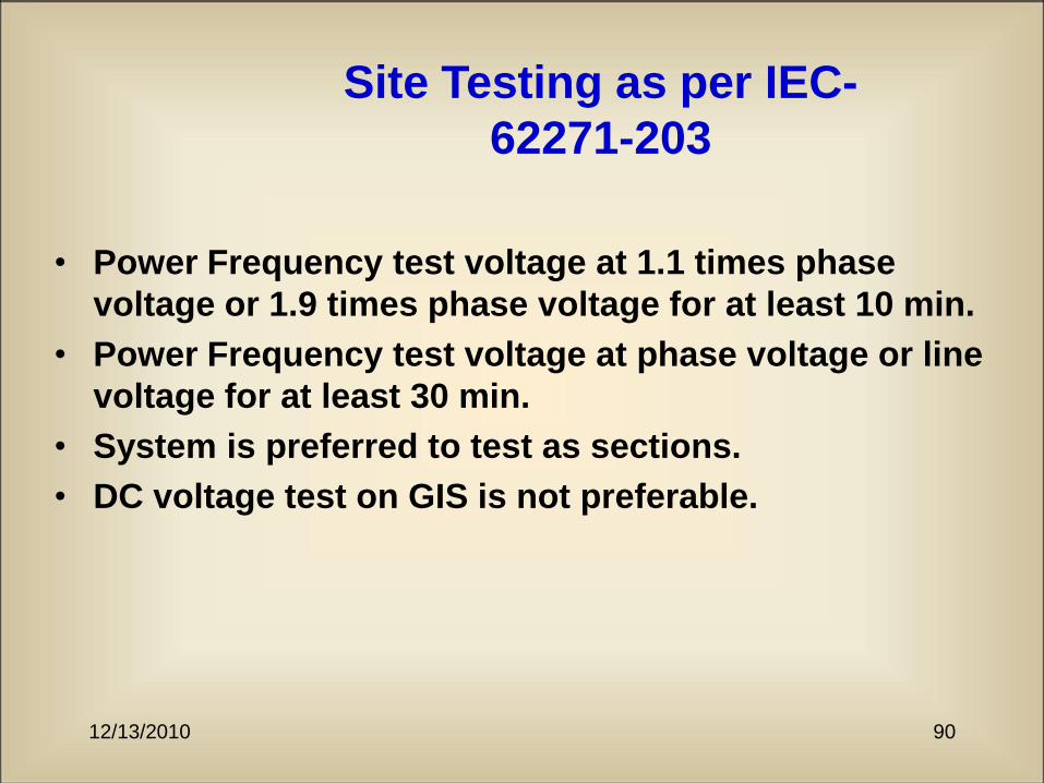
Site Testing as per IEC-
62271-203
• Power Frequency test voltage at 1.1 times phase
voltage or 1.9 times phase voltage for at least 10 min.
• Power Frequency test voltage at phase voltage or line
voltage for at least 30 min.
• System is preferred to test as sections.
• DC voltage test on GIS is not preferable.
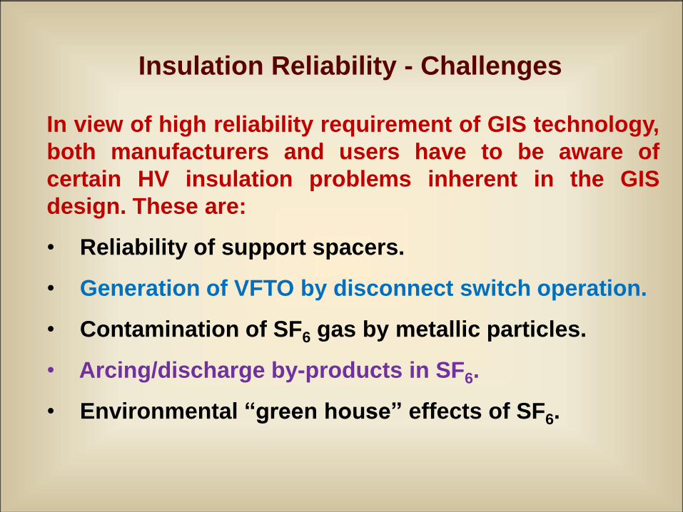
Insulation Reliability - Challenges
In view of high reliability requirement of GIS technology,
both manufacturers and users have to be aware of
certain HV insulation problems inherent in the GIS
design. These are:
• Reliability of support spacers.
• Generation of VFTO by disconnect switch operation.
• Contamination of SF6 gas by metallic particles.
• Arcing/discharge by-products in SF6.
• Environmental “green house” effects of SF6.
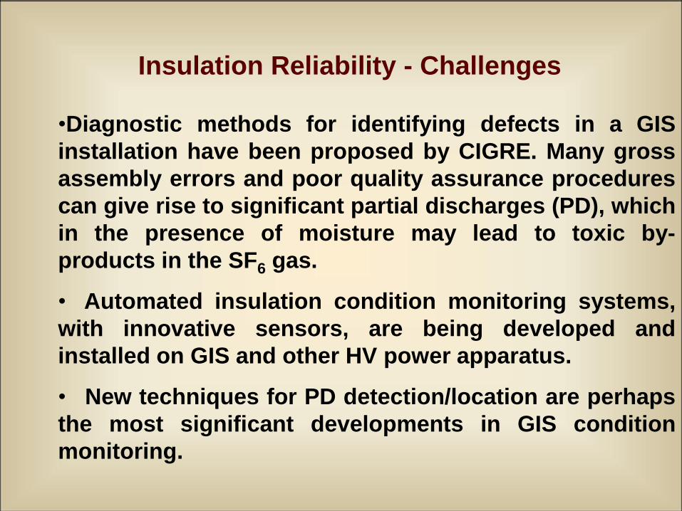
Insulation Reliability - Challenges
•Diagnostic methods for identifying defects in a GIS
installation have been proposed by CIGRE. Many gross
assembly errors and poor quality assurance procedures
can give rise to significant partial discharges (PD), which
in the presence of moisture may lead to toxic by-
products in the SF6 gas.
• Automated insulation condition monitoring systems,
with innovative sensors, are being developed and
installed on GIS and other HV power apparatus.
• New techniques for PD detection/location are perhaps
the most significant developments in GIS condition
monitoring.
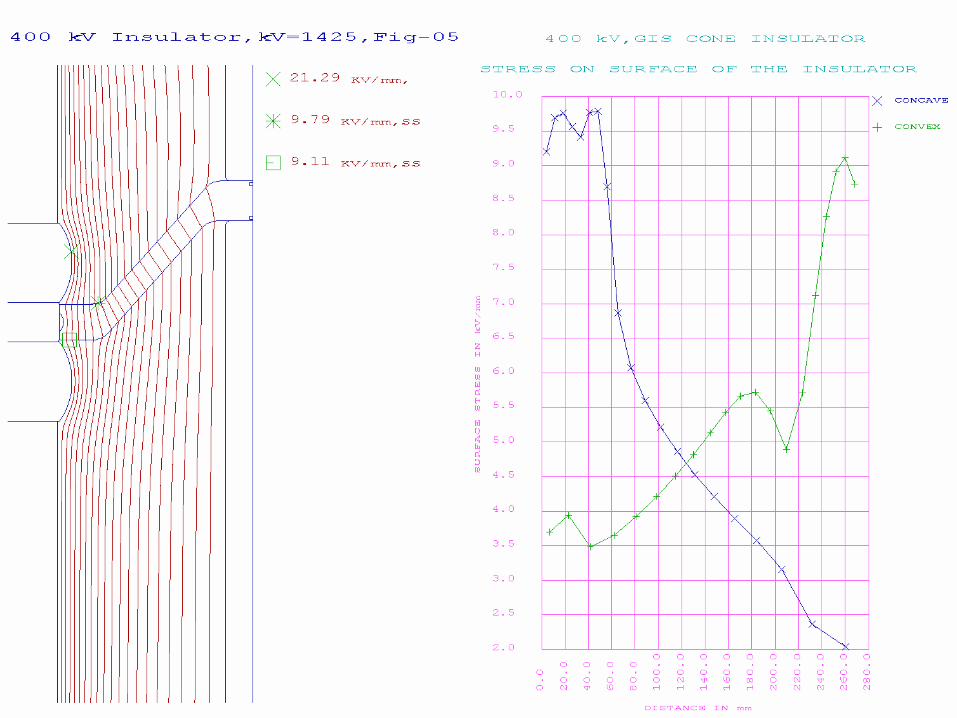
Design Principle
The electrostatic field with the insulator
should not exceed the field at the central
conductor surface without the insulator.
Very difficult to achieve!
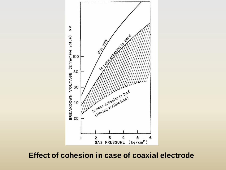
Effect of cohesion in case of coaxial electrode
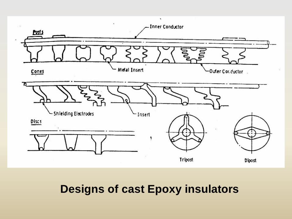
Designs of cast Epoxy insulators
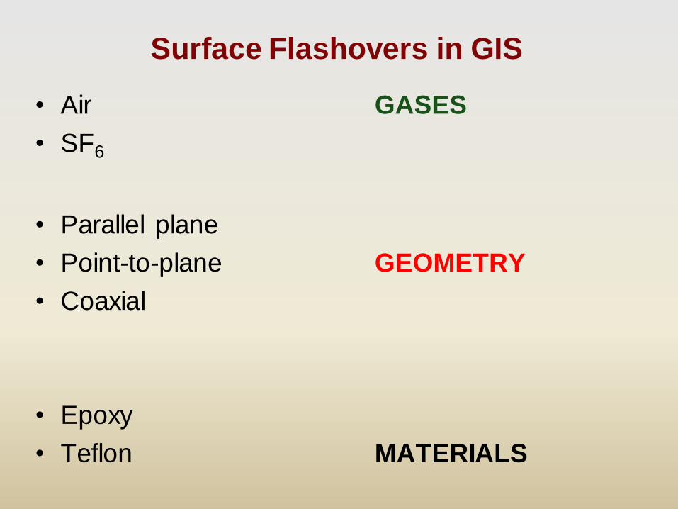
Surface Flashovers in GIS
• Air GASES
• SF6
• Parallel plane
• Point-to-plane GEOMETRY
• Coaxial
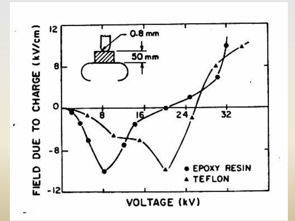
• Epoxy
• Teflon MATERIALS
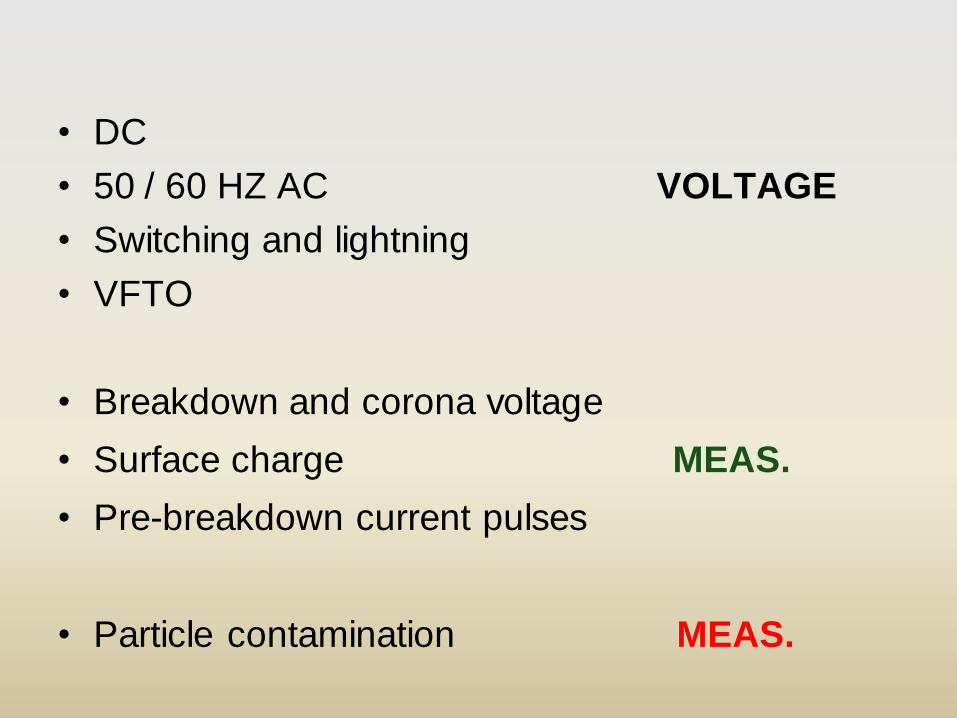
• DC
• 50 / 60 HZ AC VOLTAGE
• Switching and lightning
• VFTO
• Breakdown and corona voltage
• Surface charge MEAS.
• Pre-breakdown current pulses
• Particle contamination MEAS.
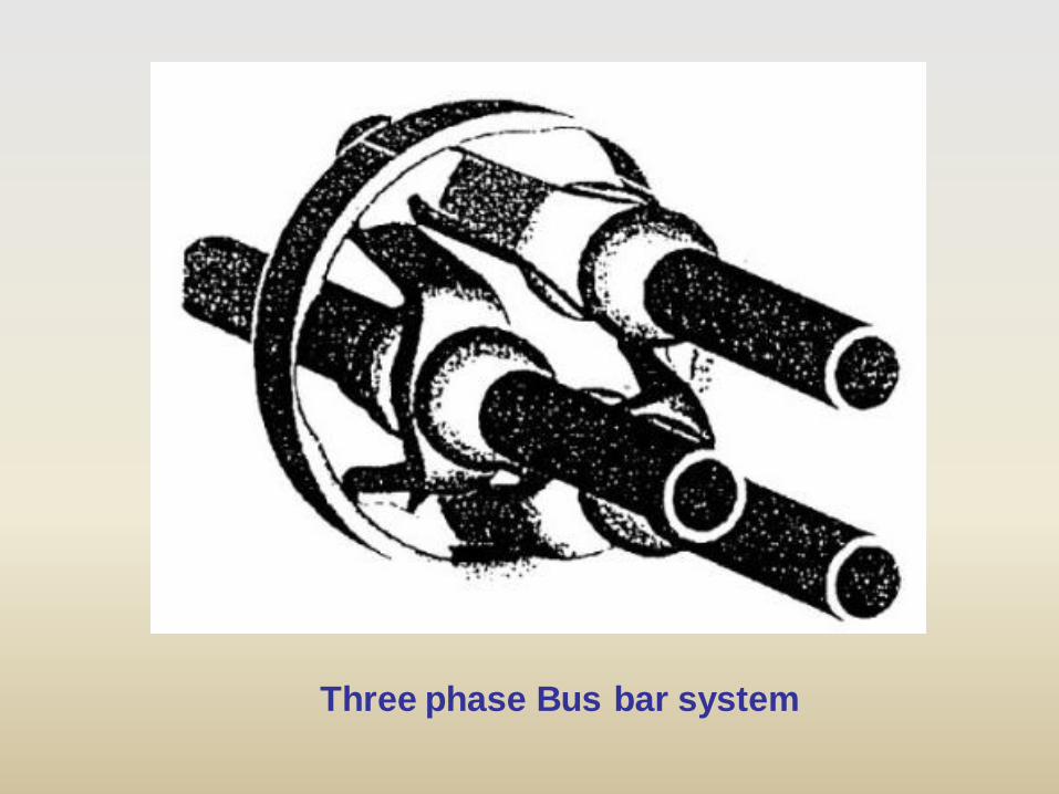
Three phase Bus bar system
12/13/2010 7
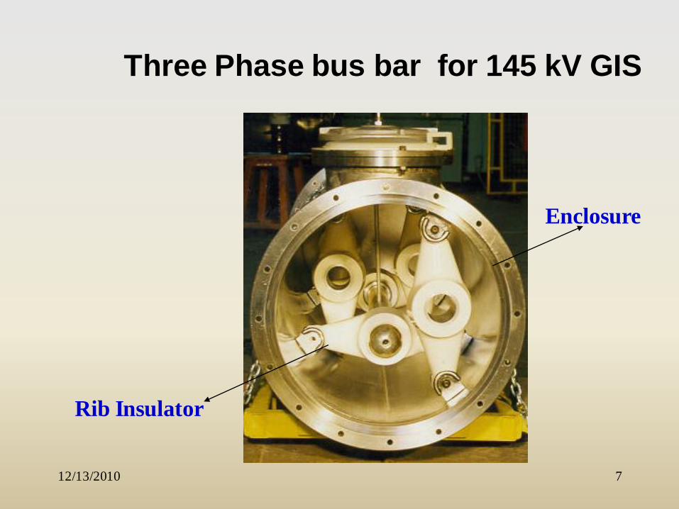
Three Phase bus bar for 145 kV GIS
Rib Insulator
Enclosure
12/13/2010 8
Technological Advancements
• Support Insulators specially designed to
avoid external pipe connection for gas
– Cone Insulators
• Non-communicating
• Communicating
– Rib Insulators
• For 3-phase systems
12/13/2010 9
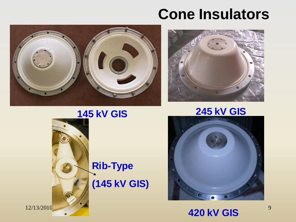
Cone Insulators
245 kV GIS
Rib-Type
(145 kV GIS)
420 kV GIS
145 kV GIS
Critical Problems
1. Triple-junction design
2. Tangenital vs. normal field at the insulator
3. Surface discharges from partial discharges
4. Presence of metallic particles on the insulator
surface
5. For D.C. applications - the problem of bulk
charging of insulator
6. Poor quality material - voids & other defects
Reliability of Support Spacers
• Bulk failure is rare - but voids, protrusions, conducting
contaminants may cause sustained discharges in the bulk
and lead to failure.
• Casting is a high temperature process and differential
cooling and contaminants in the filler (Al2O3) have to be
minimized by strict quality control.
• Very often the PD level generated by these defects is
below the detection sensitivity of 1pc.
• “Intrinsic breakdown of epoxy spacer is rare- but the
material does age.
• Economic pressure to reduce spacer dimension since this
will affect the enclosure diameter.
Reliability of Support Spacers
• Early designs operating AC stress was 10 kV/mm (rms) at
maximum locations. Many of these failed in service in
about 5 years.
• Typical stresses now range from 2 kV/mm (rms) at 145 kV
and 4.1 kV/mm (rms) at 800 kV. But some high voltage
designs still use 5-6 kV/mm (rms).
• Another factor is the reduced margin between BIL and
operating stress as the voltage class becomes higher.
• PD detection requires increasing detection sensitivity as
the spacer size increases with voltage level of GIS.
• For example, 550 / 800 kV spacer should perhaps be
tested with a detection sensitivity of about 0.5 pc. Such a
level is difficult to achieve in a factory.
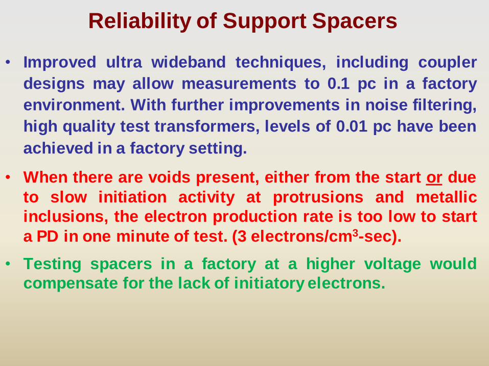
Reliability of Support Spacers
• Improved ultra wideband techniques, including coupler
designs may allow measurements to 0.1 pc in a factory
environment. With further improvements in noise filtering,
high quality test transformers, levels of 0.01 pc have been
achieved in a factory setting.
• When there are voids present, either from the start or due
to slow initiation activity at protrusions and metallic
inclusions, the electron production rate is too low to start
a PD in one minute of test. (3 electrons/cm3-sec).
• Testing spacers in a factory at a higher voltage would
compensate for the lack of initiatory electrons.
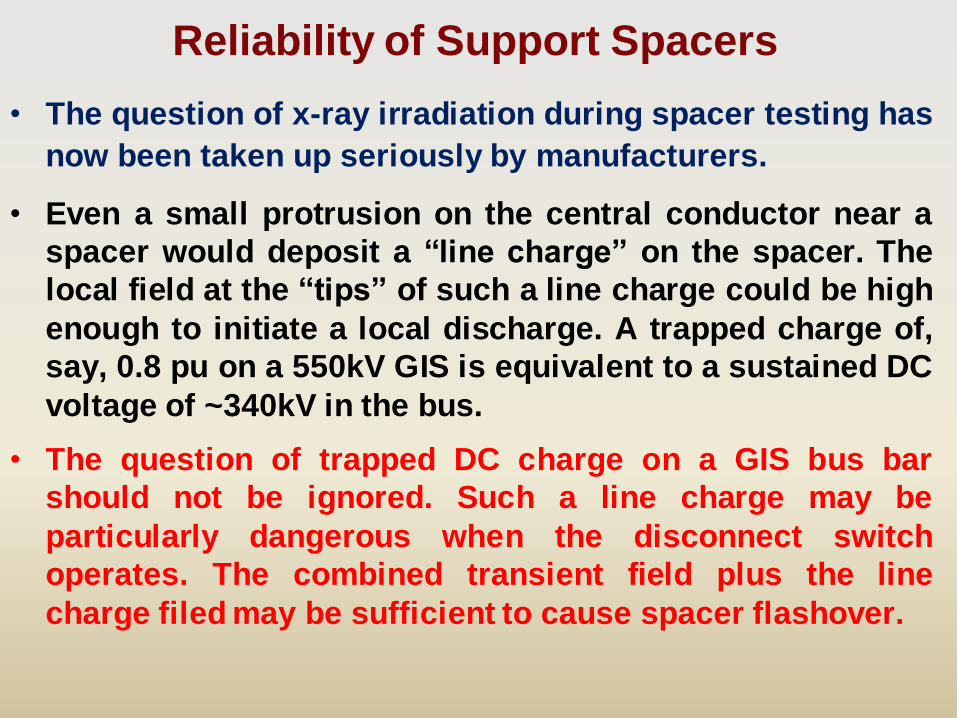
Reliability of Support Spacers
• The question of x-ray irradiation during spacer testing has
now been taken up seriously by manufacturers.
• Even a small protrusion on the central conductor near a
spacer would deposit a “line charge” on the spacer. The
local field at the “tips” of such a line charge could be high
enough to initiate a local discharge. A trapped charge of,
say, 0.8 pu on a 550kV GIS is equivalent to a sustained DC
voltage of ~340kV in the bus.
• The question of trapped DC charge on a GIS bus bar
should not be ignored. Such a line charge may be
particularly dangerous when the disconnect switch
operates. The combined transient field plus the line
charge filed may be sufficient to cause spacer flashover.
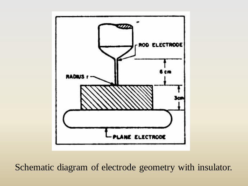
Schematic diagram of electrode geometry with insulator.
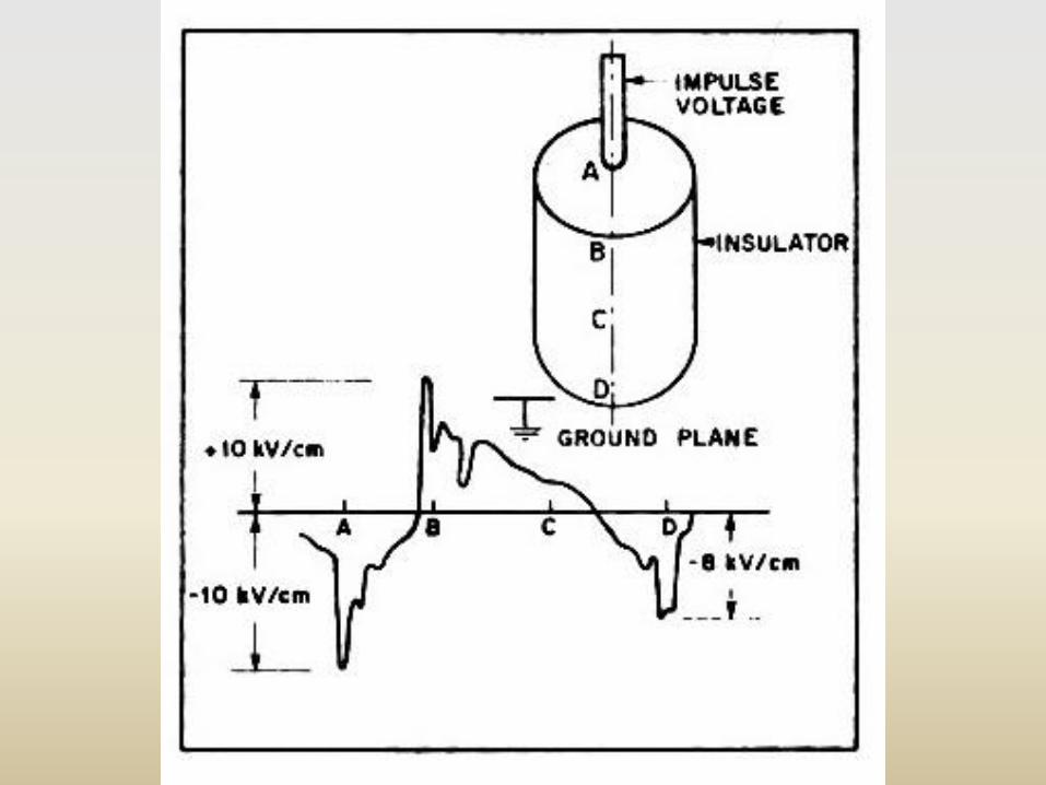
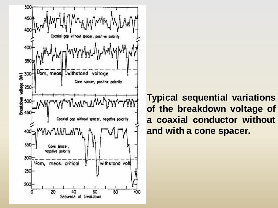
Typical sequential variations
of the breakdown voltage of
a coaxial conductor without
and with a cone spacer.
• Insulating spacers are widely used in high-voltage power
apparatus. From a withstand voltage of view spacers are
the weakest components and an improvement in the
understanding of surface flashover characteristics of
such solid insulators is beneficial for better designs of
power apparatus.
• In the bus bar of GIS there could be trapped charge
after disconnect switch operations. The electrical
stress created by these charges can lower the
withstand voltage.
Effect of Trapped charge
• From extensive research work, it was found the surface
charge accumulated on the spacer surface after applied
impulse voltage or DS operation.
• The application of DC pre-stressing will approximate
conditions resulting from disconnect operation or
lightning/switching surge. Work was undertaken to
determine the changes, if any, in the early stages of the
surface breakdown under lightning impulse voltage
when there is a prior direct stress.
Trapped charge – DC prestressing
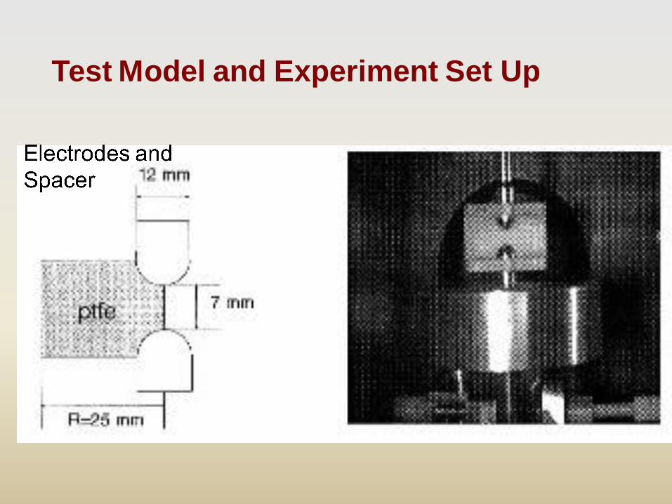
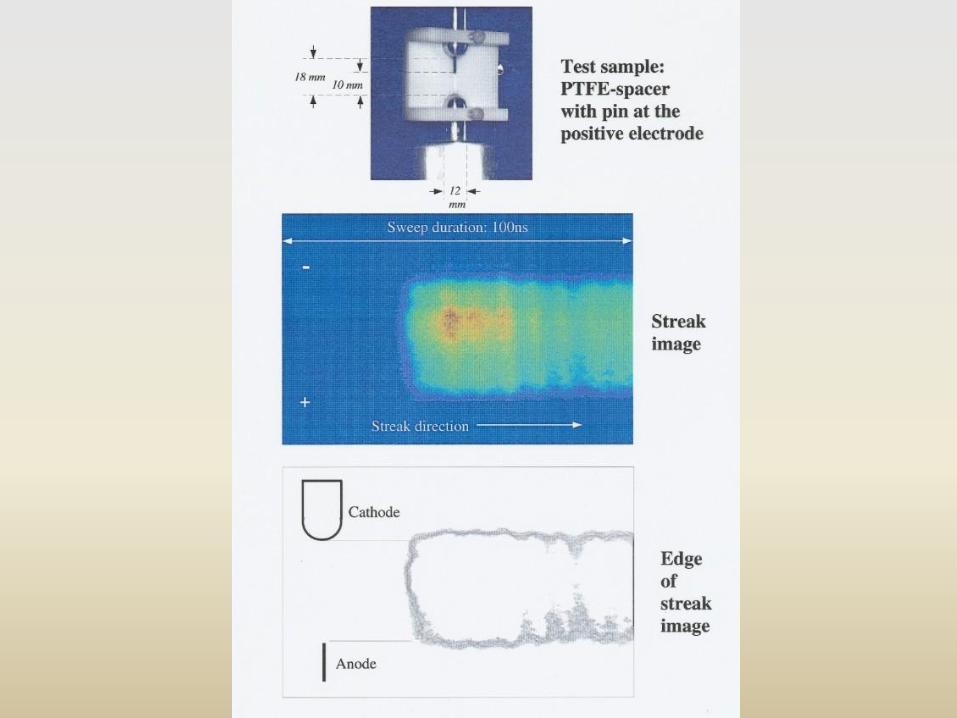
Test Model and Experiment Set Up
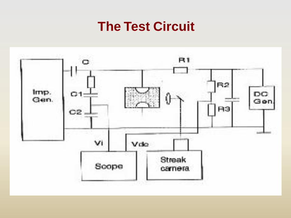
The Test Circuit
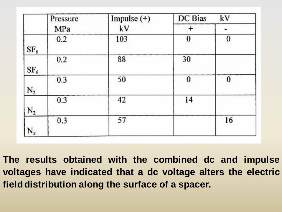
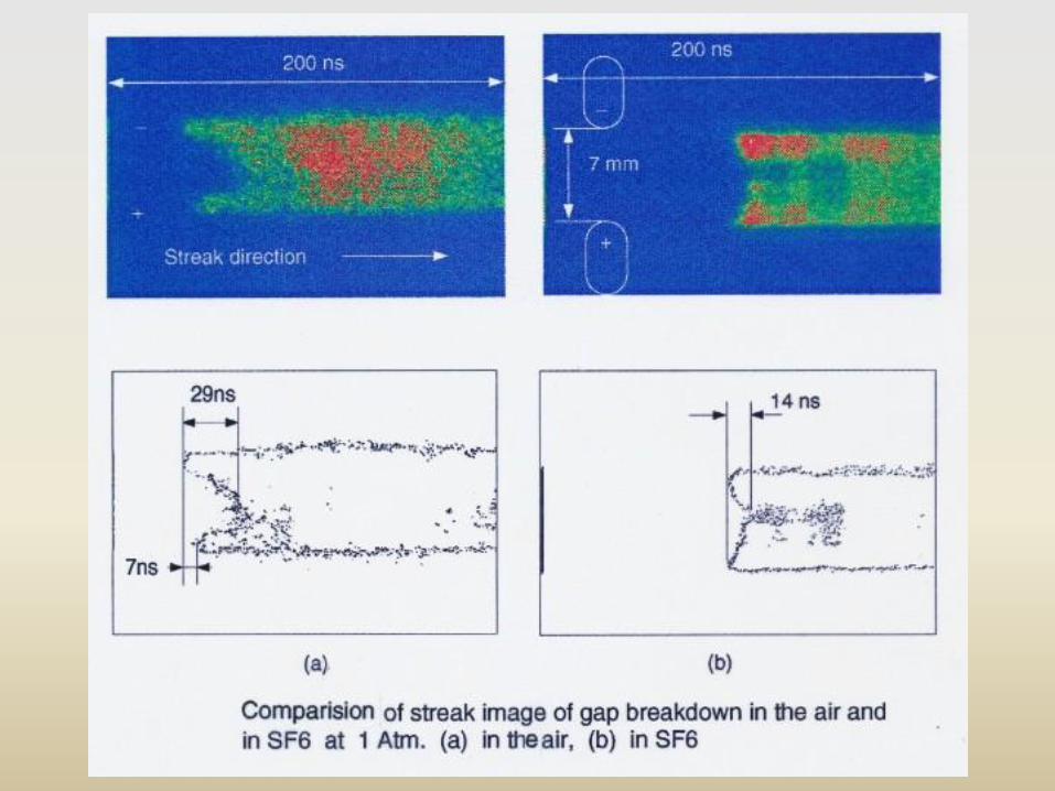
The results obtained with the combined dc and impulse
voltages have indicated that a dc voltage alters the electric
field distribution along the surface of a spacer.
• From the experiments, it is clear that the initiation glow
of flashover on insulator is at somewhere between two
electrodes. There would be local field enhancements at
several places. It is not justifiable to employ spacers
with perfect or near perfect surfaces. Hence,
improvements in the withstand voltage can only be
obtained by preventing field enhancements through
other means such as a weakly conductive coating.
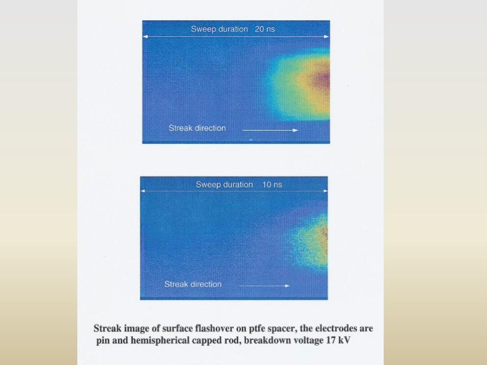
• The development of flashover when there is a dc initial
voltage is much more rapid than when there is no dc voltage.
The rapid flashover development can give rise to fast-fronted
transients in the substation.
Trapped charge : DC pre-stressing
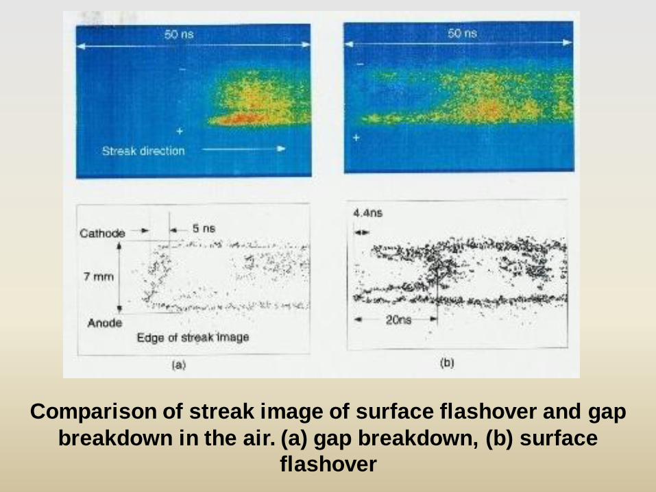
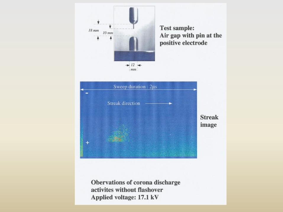
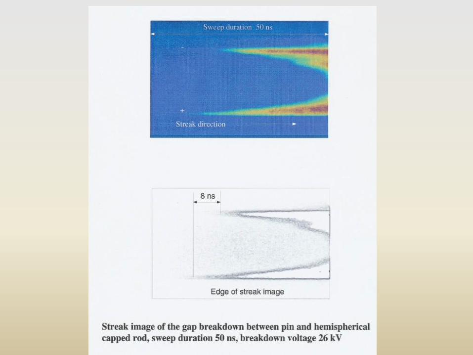
Comparison of streak image of surface flashover and gap
breakdown in the air. (a) gap breakdown, (b) surface
flashover
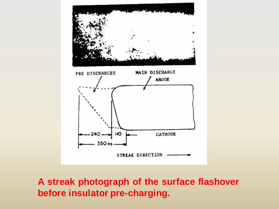
A streak photograph of the surface flashover
before insulator pre-charging.


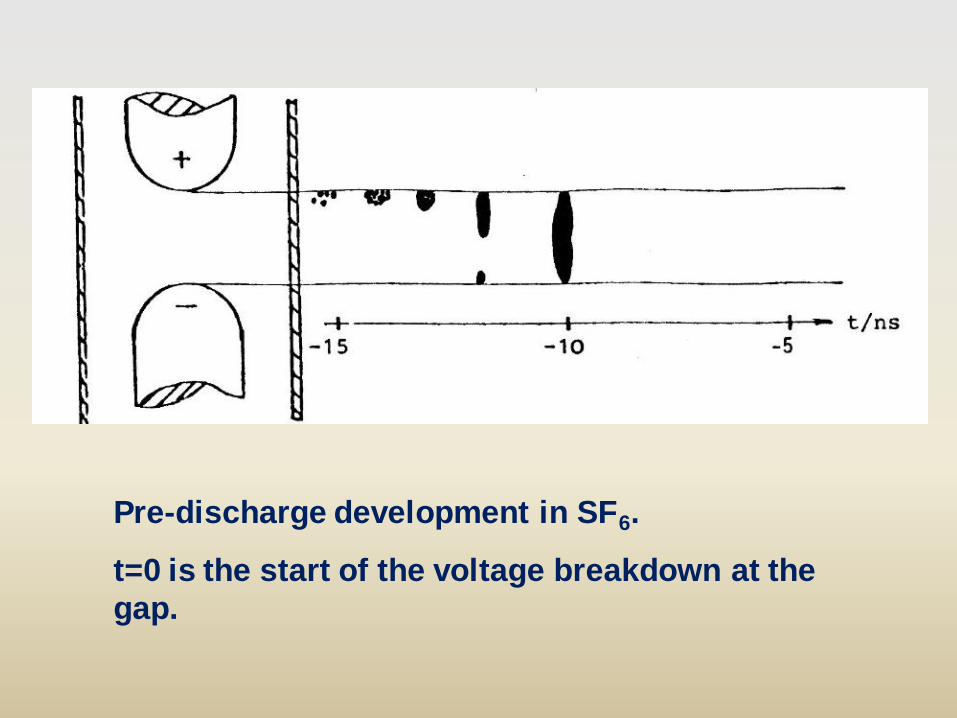
Pre-discharge development in SF6.
t=0 is the start of the voltage breakdown at the
gap.

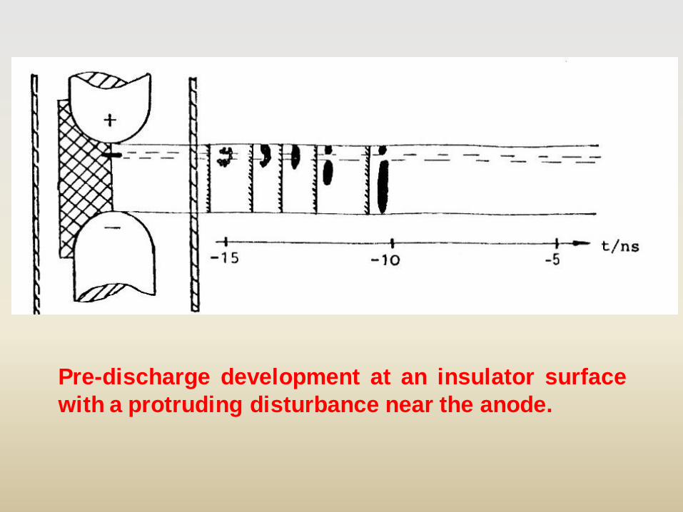
Pre-discharge development at an insulator surface
with a disturbance near the anode.
It is evident that the pre-discharge formation occurs in
the space between disturbance and cathode. As the
discharge proceeds in cathode direction the gap between
anode and the disturbance in this case is also bridged
simultaneously.
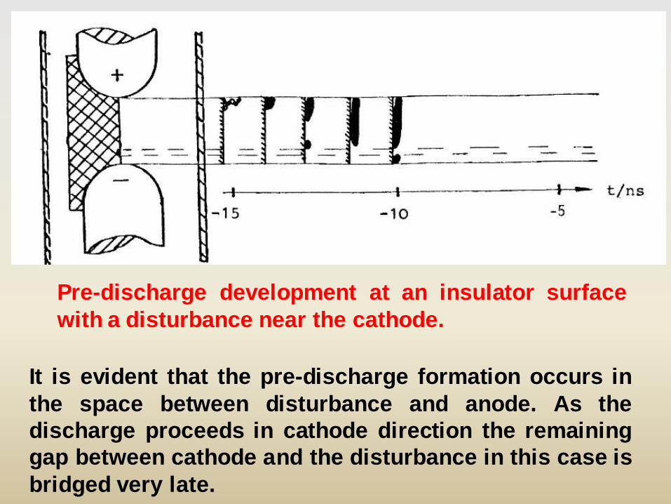
It is evident that the pre-discharge formation occurs in
the space between disturbance and anode. As the
discharge proceeds in cathode direction the remaining
gap between cathode and the disturbance in this case is
bridged very late.
Pre-discharge development at an insulator surface
with a disturbance near the cathode.
Pre-discharge development at an insulator surface
with a protruding disturbance near the anode.
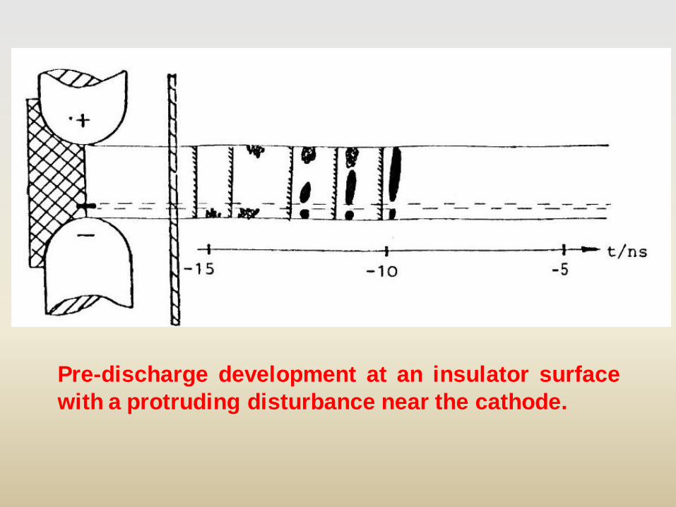
Pre-discharge development at an insulator surface
with a protruding disturbance near the cathode.
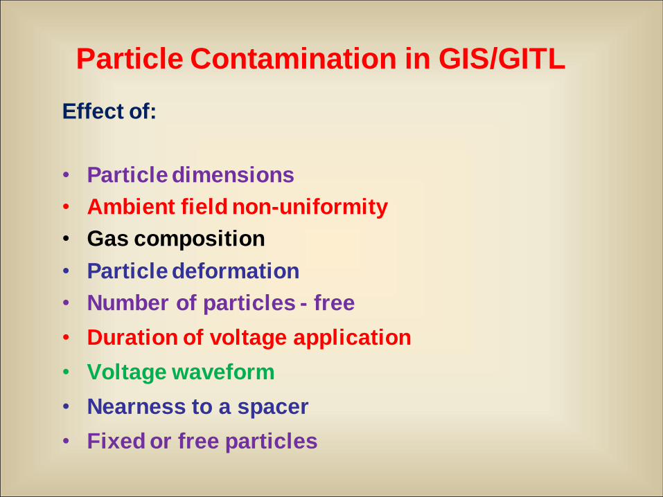
Particle Contamination in GIS/GITL
Effect of:
• Particle dimensions
• Ambient field non-uniformity
• Gas composition
• Particle deformation
• Number of particles - free
• Duration of voltage application
• Voltage waveform
• Nearness to a spacer
• Fixed or free particles
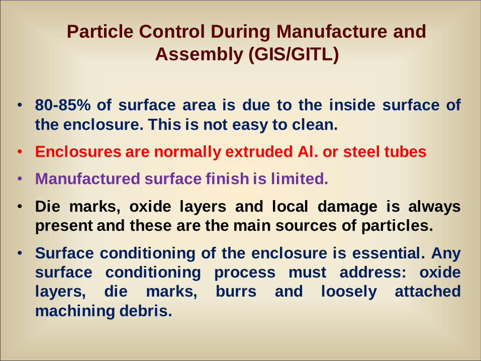
Particle Control During Manufacture and
Assembly (GIS/GITL)
• 80-85% of surface area is due to the inside surface of
the enclosure. This is not easy to clean.
• Enclosures are normally extruded Al. or steel tubes
• Manufactured surface finish is limited.
• Die marks, oxide layers and local damage is always
present and these are the main sources of particles.
• Surface conditioning of the enclosure is essential. Any
surface conditioning process must address: oxide
layers, die marks, burrs and loosely attached
machining debris.
Sources of Metal Particles in GIS
• Machining debris
• Expansion joints
• Poor mechanical assembly
• Other defects in metal parts
Possible particle locations
1. Fixed on phase conductor
2. Fixed on enclosure
3. Free to move in elec. field
4. Fixed on spacer
Free particle movement is different under DC, AC
and Impulse voltages.
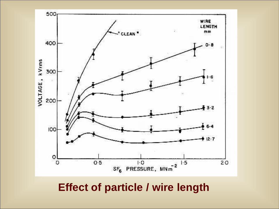
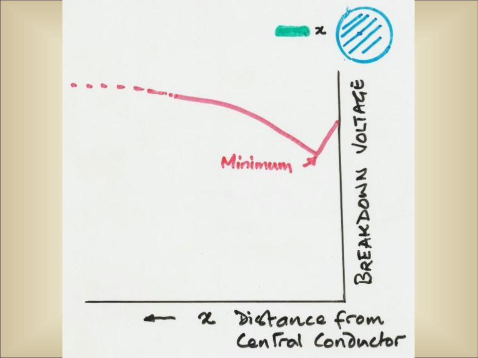
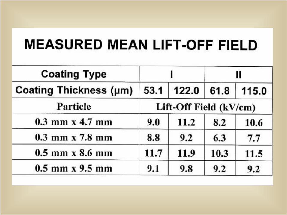
Effect of particle / wire length
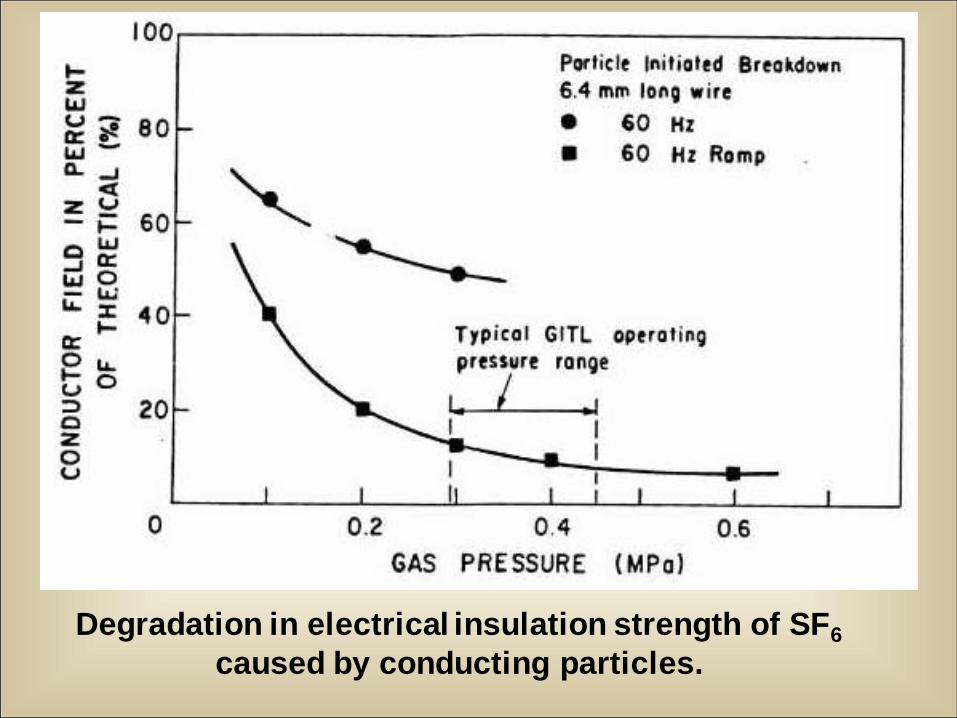
Degradation in electrical insulation strength of SF6
caused by conducting particles.
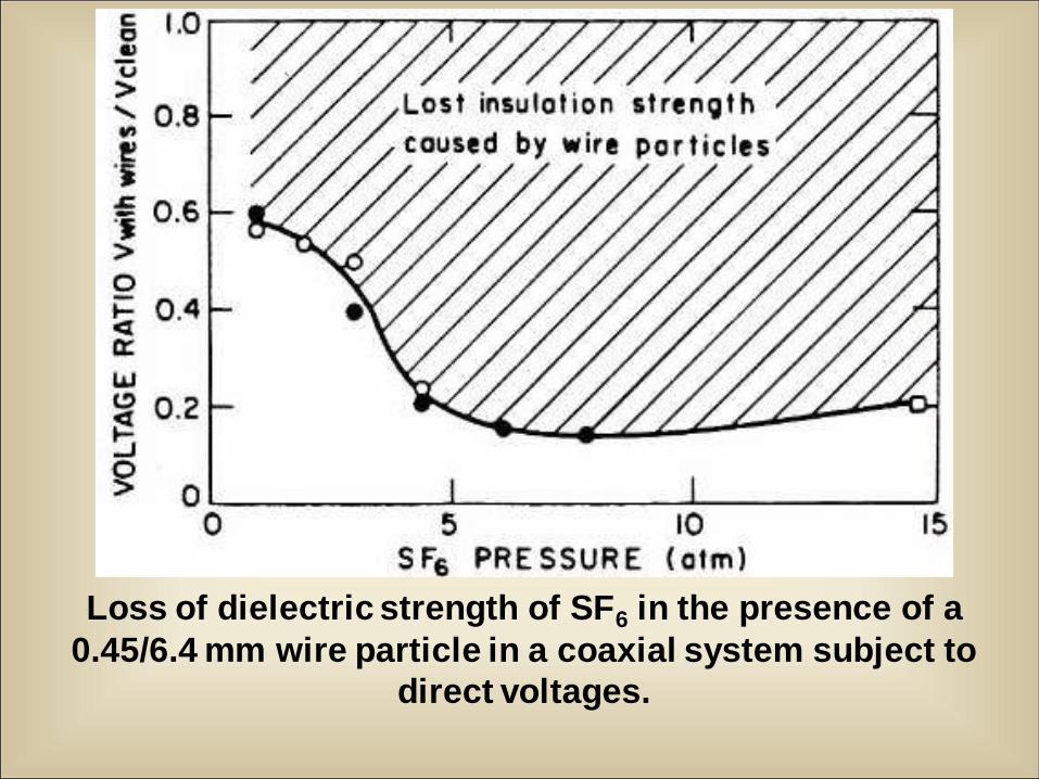
Loss of dielectric strength of SF6 in the presence of a
0.45/6.4 mm wire particle in a coaxial system subject to
direct voltages.
Hjk
L;l
L;l
L;l
H
L
L
L
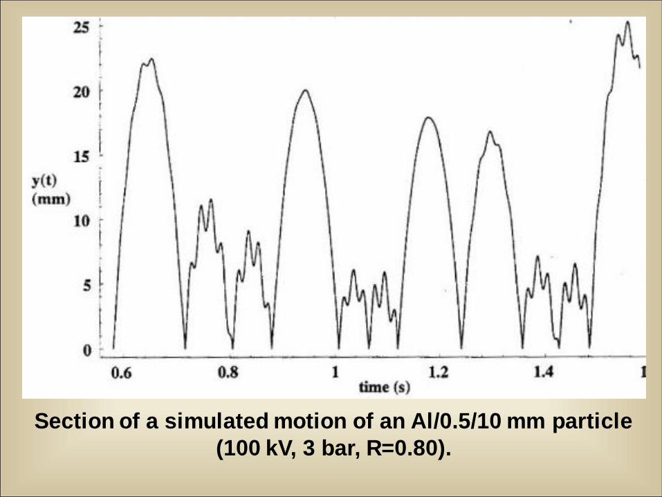
Section of a simulated motion of an Al/0.5/10 mm particle
(100 kV, 3 bar, R=0.80).
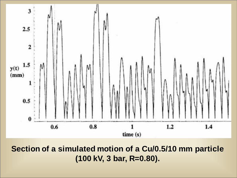
Section of a simulated motion of a Cu/0.5/10 mm particle
(100 kV, 3 bar, R=0.80).
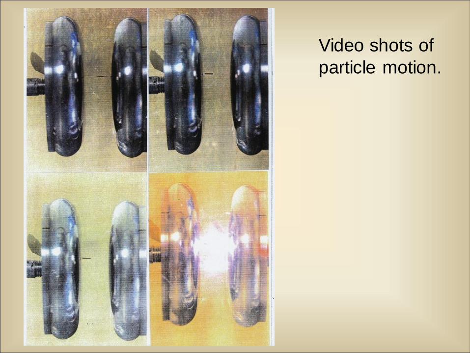
Video shots of
particle motion.
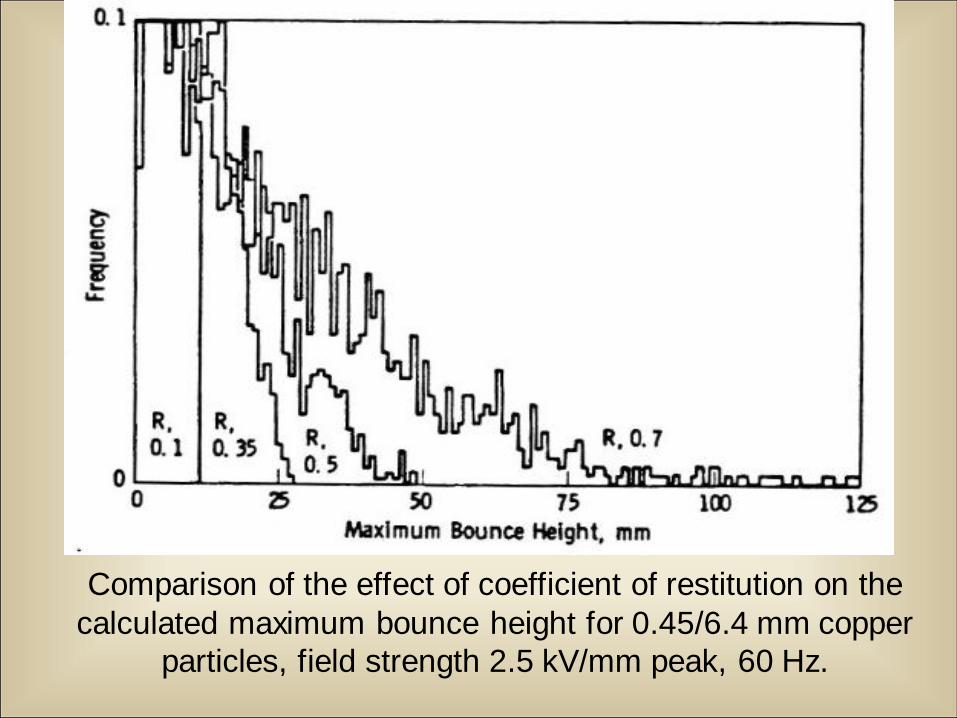
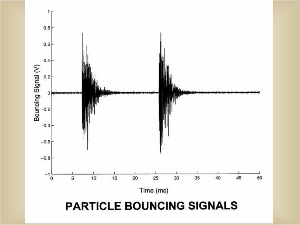
Comparison of the effect of coefficient of restitution on the
calculated maximum bounce height for 0.45/6.4 mm copper
particles, field strength 2.5 kV/mm peak, 60 Hz.
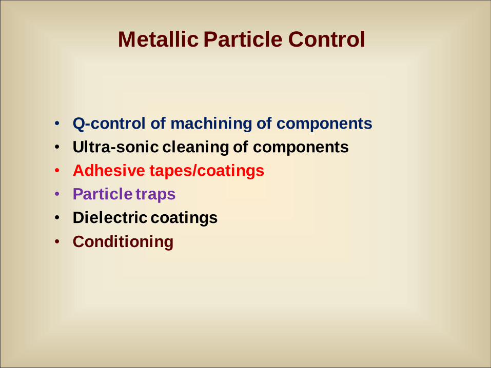
Metallic Particle Control
• Q-control of machining of components
• Ultra-sonic cleaning of components
• Adhesive tapes/coatings
• Particle traps
• Dielectric coatings
• Conditioning
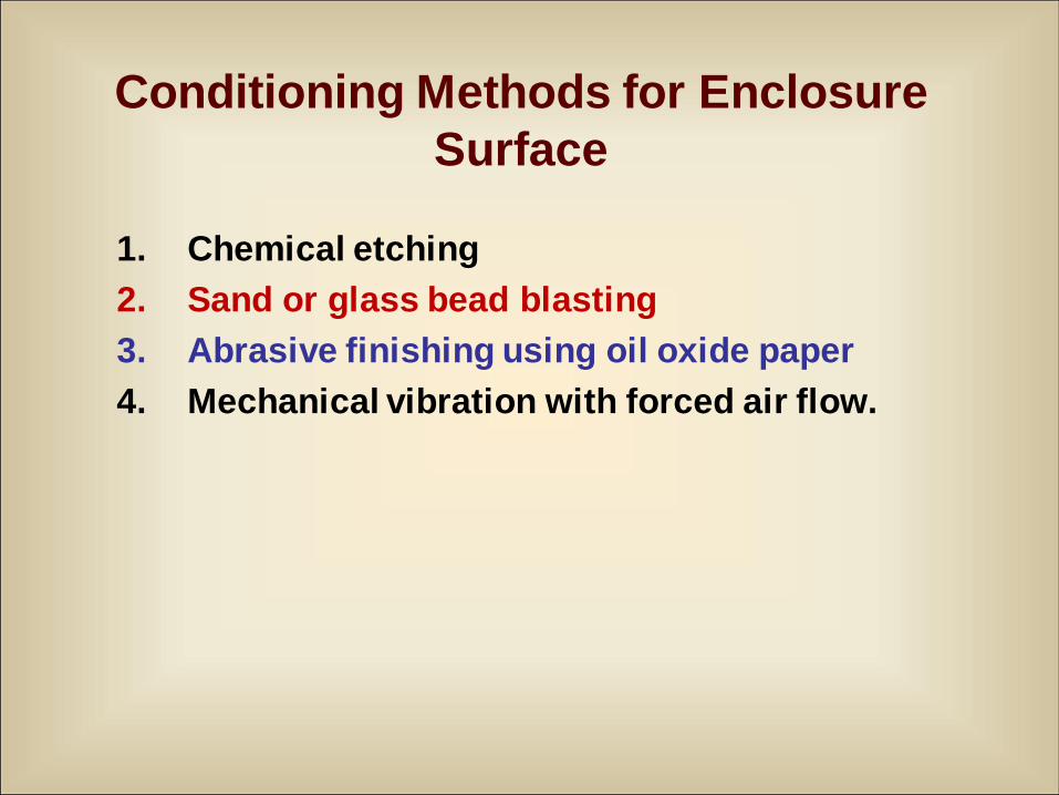
Conditioning Methods for Enclosure
Surface
1. Chemical etching
2. Sand or glass bead blasting
3. Abrasive finishing using oil oxide paper
4. Mechanical vibration with forced air flow.
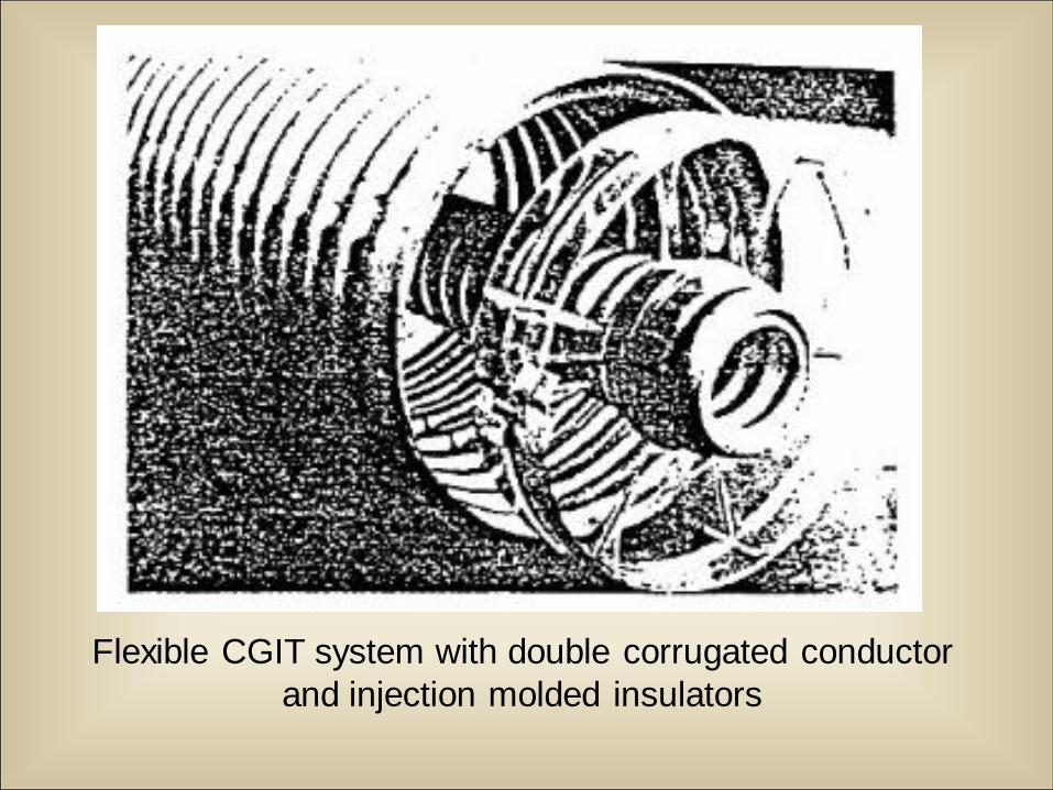
Flexible CGIT system with double corrugated conductor
and injection molded insulators
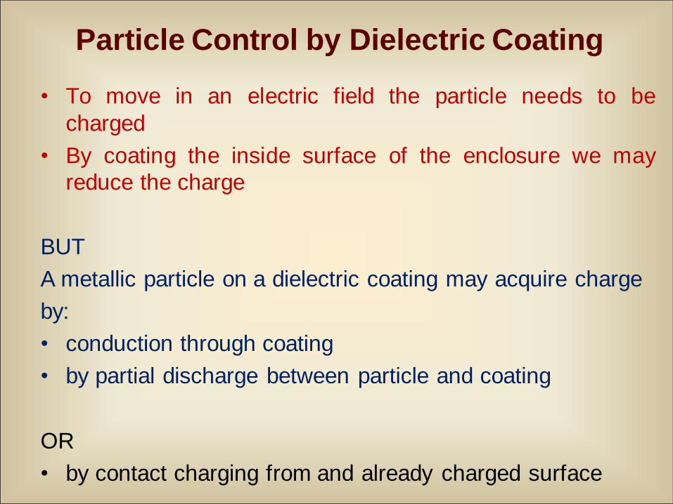
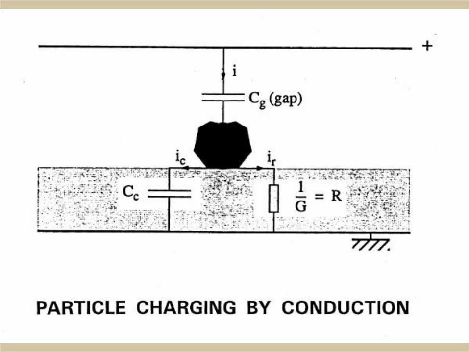
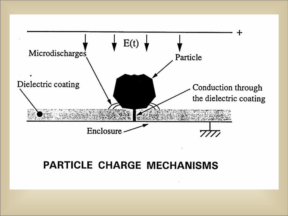
Particle Control by Dielectric Coating
• To move in an electric field the particle needs to be
charged
• By coating the inside surface of the enclosure we may
reduce the charge
BUT
A metallic particle on a dielectric coating may acquire charge
by:
• conduction through coating
• by partial discharge between particle and coating
OR
• by contact charging from and already charged surface
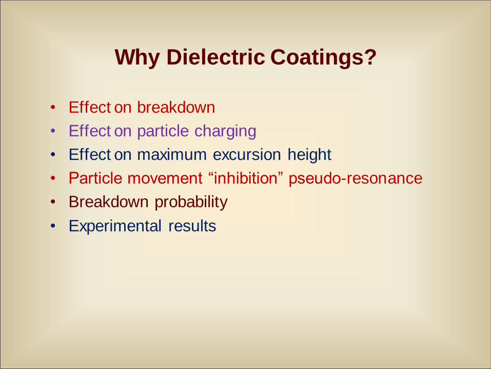
• Effect on breakdown
• Effect on particle charging
• Effect on maximum excursion height
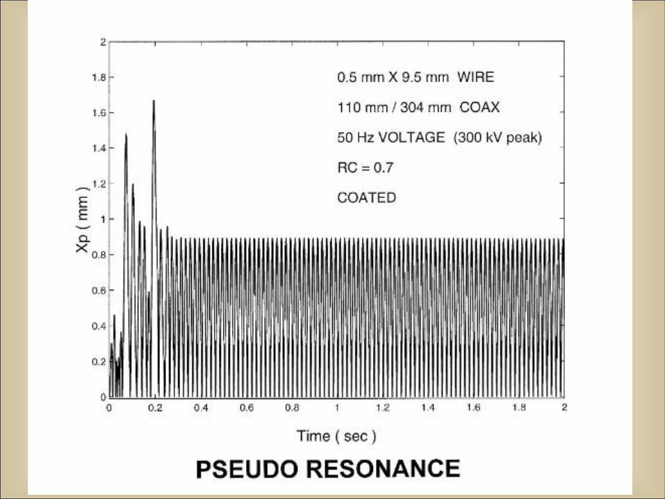
• Particle movement “inhibition” pseudo-resonance
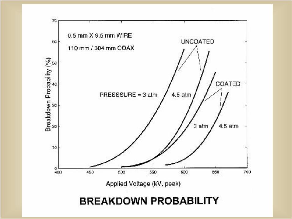
• Breakdown probability
• Experimental results
Why Dielectric Coatings?
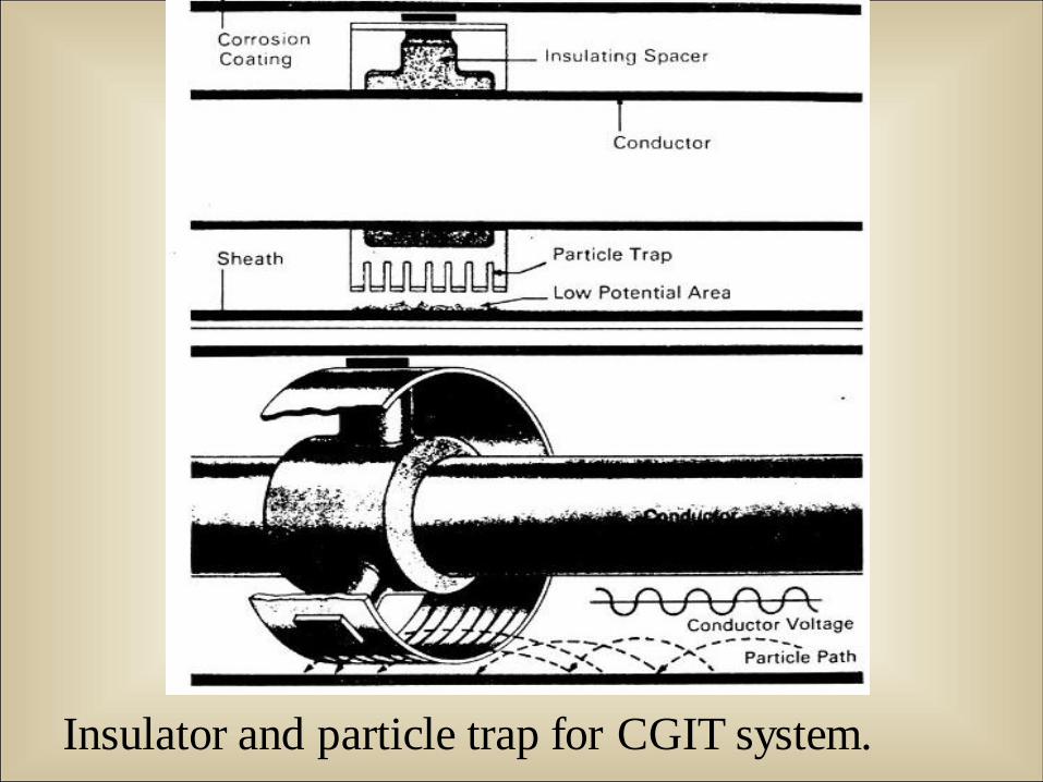
Insulator and particle trap for CGIT system.
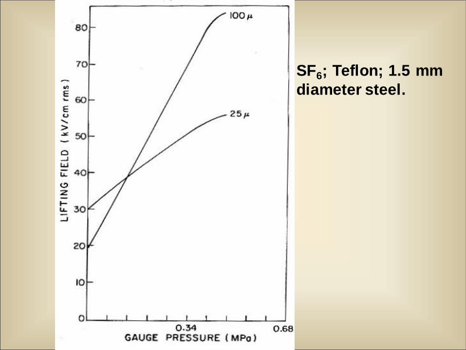
SF6; Teflon; 1.5 mm
diameter steel.
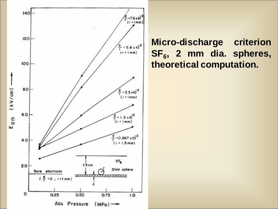
Micro-discharge criterion
SF6, 2 mm dia. spheres,
theoretical computation.
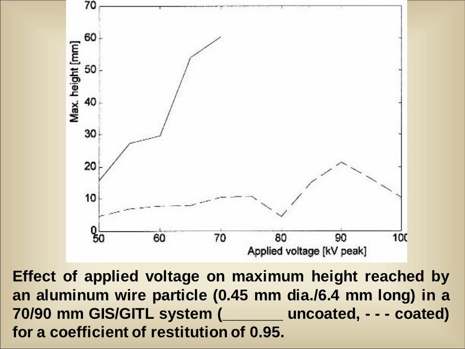
Effect of applied voltage on maximum height reached by
an aluminum wire particle (0.45 mm dia./6.4 mm long) in a
70/90 mm GIS/GITL system (_______ uncoated, - - - coated)
for a coefficient of restitution of 0.95.
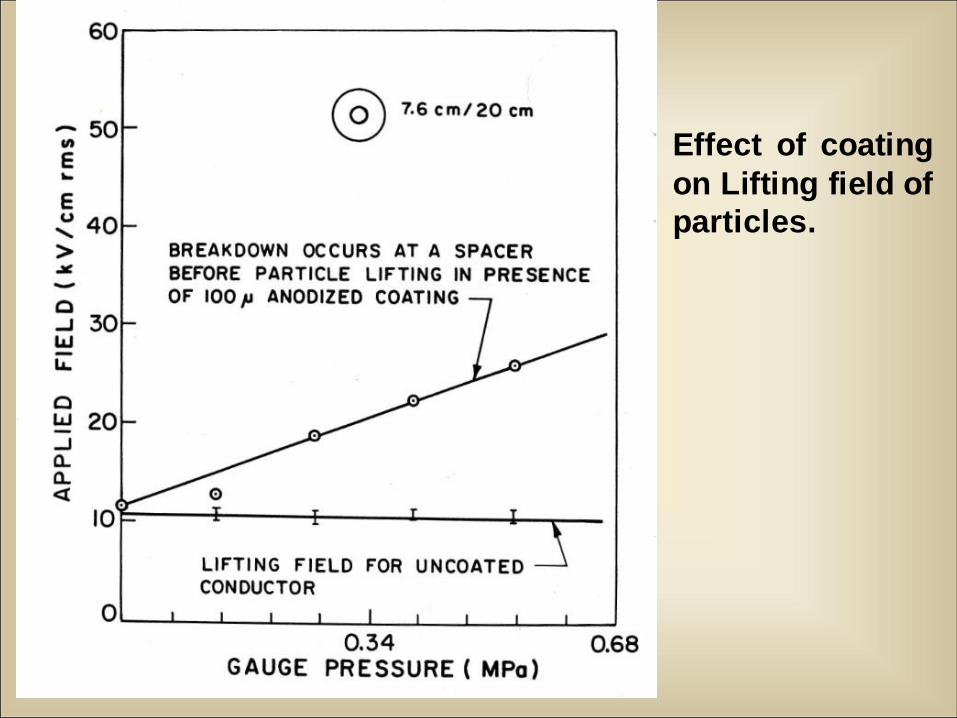
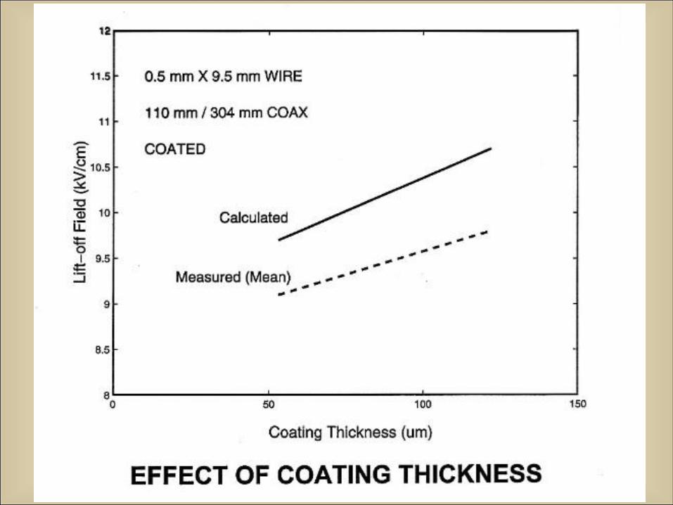
Effect of coating
on Lifting field of
particles.
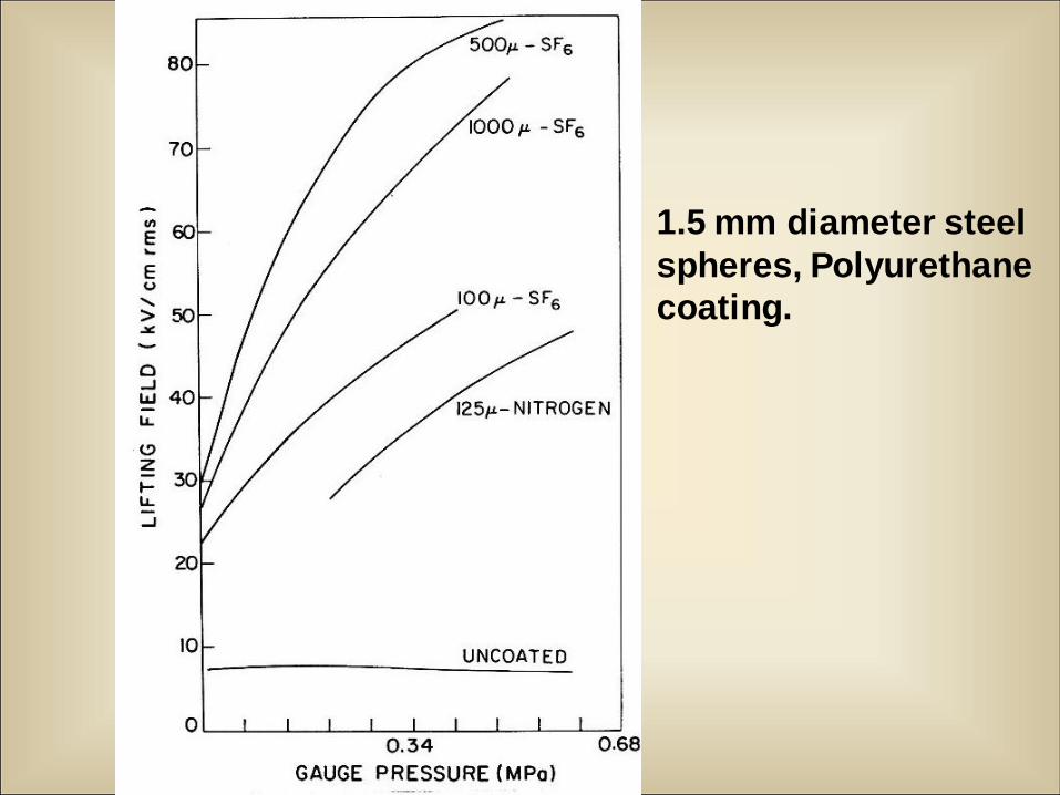
1.5 mm diameter steel
spheres, Polyurethane
coating.
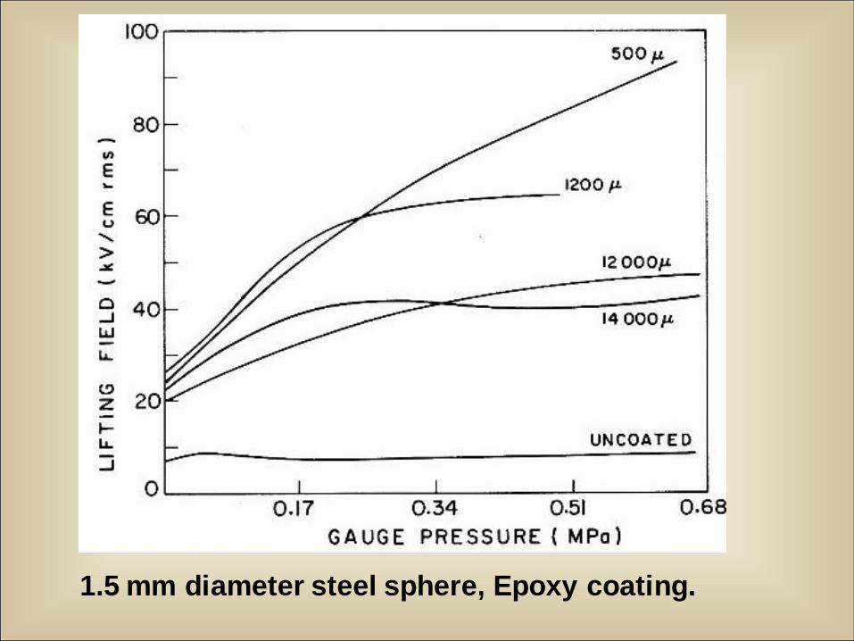
1.5 mm diameter steel sphere, Epoxy coating.
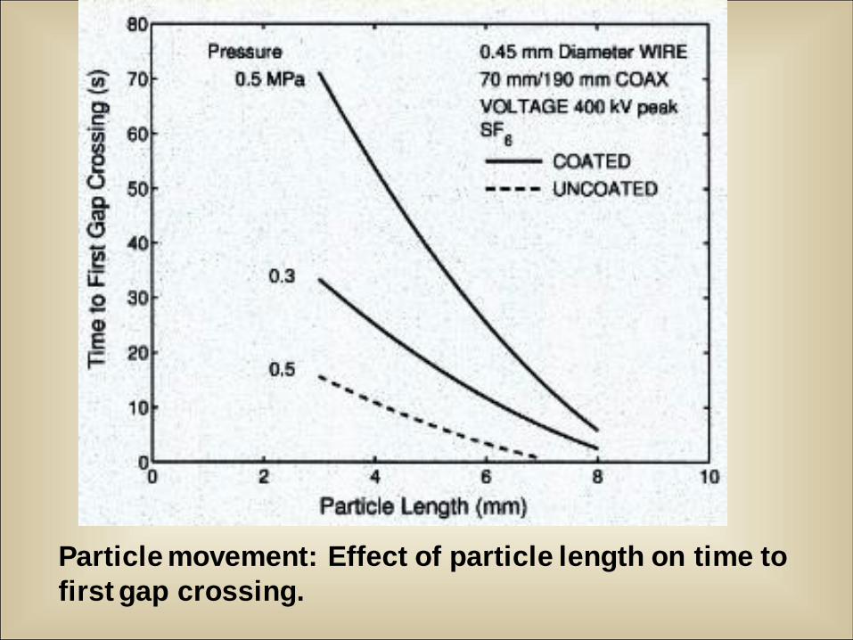
Particle movement: Effect of particle length on time to
first gap crossing.
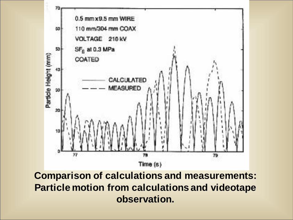
Comparison of calculations and measurements:
Particle motion from calculations and videotape
observation.
12/13/2010 33
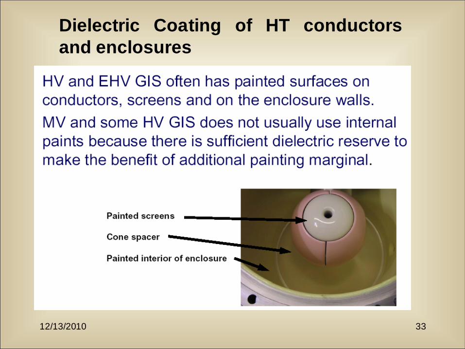
Dielectric Coating of HT conductors
and enclosures
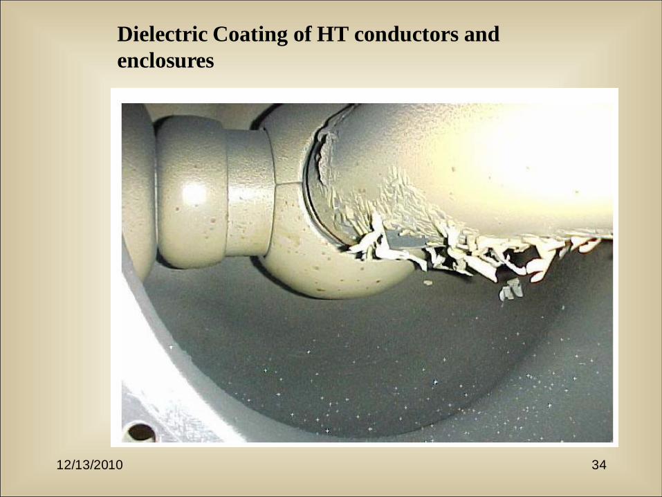
12/13/2010 34
Dielectric Coating of HT conductors and
enclosures
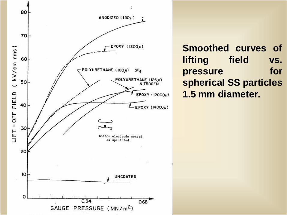
Smoothed curves of
lifting field vs.
pressure for
spherical SS particles
1.5 mm diameter.
h j
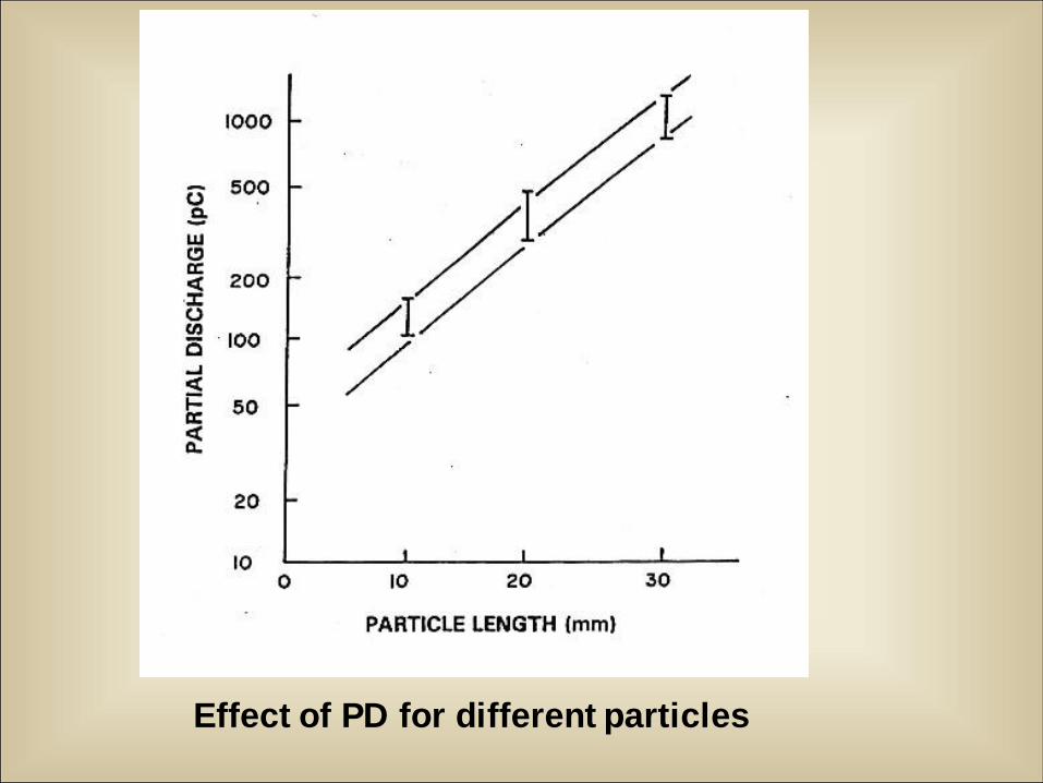
Effect of PD for different particles
Very Fast Transient Over voltages
(VFTO) and Transient Enclosure
Voltages (TEV) During GIS Operation
Dr. M. Mohana Rao
BHEL Corporate R&D
Hyderabad
E-mail: [email protected]
What is VFT?
In a GIS, Very Fast Transient Over voltages (VFTO) are generated
mainly due to switching operations.
The voltage collapse across switching contacts takes place in 3 to
20 ns depending on breakdown voltage, electric field non-
uniformity and operating gas pressure.
The short-rise time pulse (i.e., voltage collapse) starts at the
switching contacts that propagate along the gas insulated bus
sections/components and take reflections at different terminations.
Because of superposition of the original pulse with the reflected
pulse, VFTO are developed.
The waveform of these transients depends on the configuration of
the GIS. The VFTO levels are found to be on the higher side for the
following conditions of the switching configurations:
(1) Small length of bus sections on the load side of the switch.
(2). High surge capacitance components on source side of switch
(3.0 P.u.).
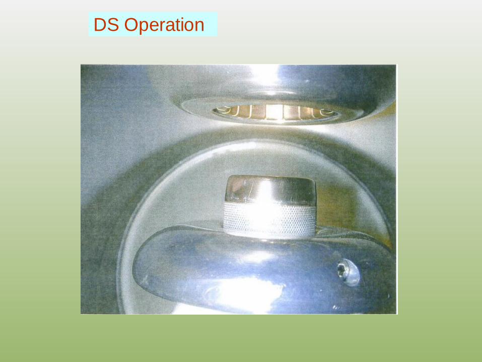
DS Operation
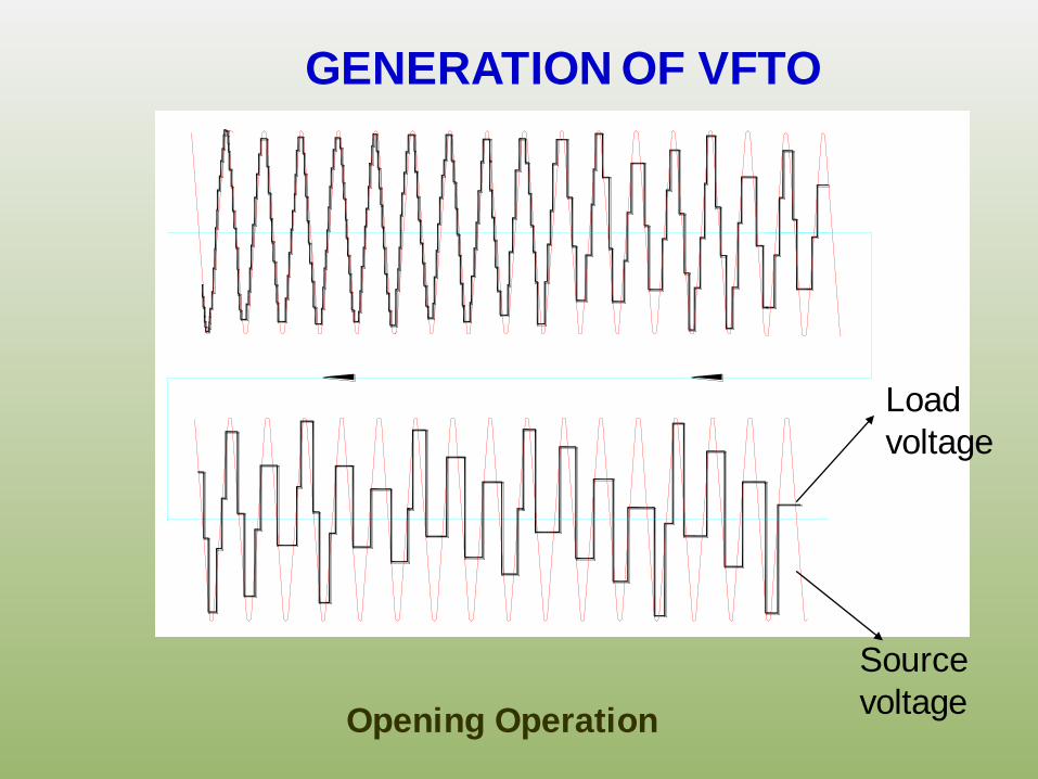
GENERATION OF VFTO
Opening Operation
Load
voltage
Source
voltage
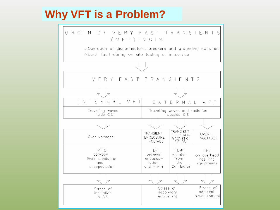
Why VFT is a Problem?
12/13/2010 6
Earthing of GIS
GIS Earthing is possible in Two ways:
1. Single Point Earthing
2. Multi-point Earthing.
In single point earthing each enclosure is isolated from
next one and grounded each enclosure at only one
point so that no loop currents.
In multiple point earthing enclosures are electrically
connected and grounded at many locations. In addition
the enclosures of the different phases are connected by
shunts.
12/13/2010 7
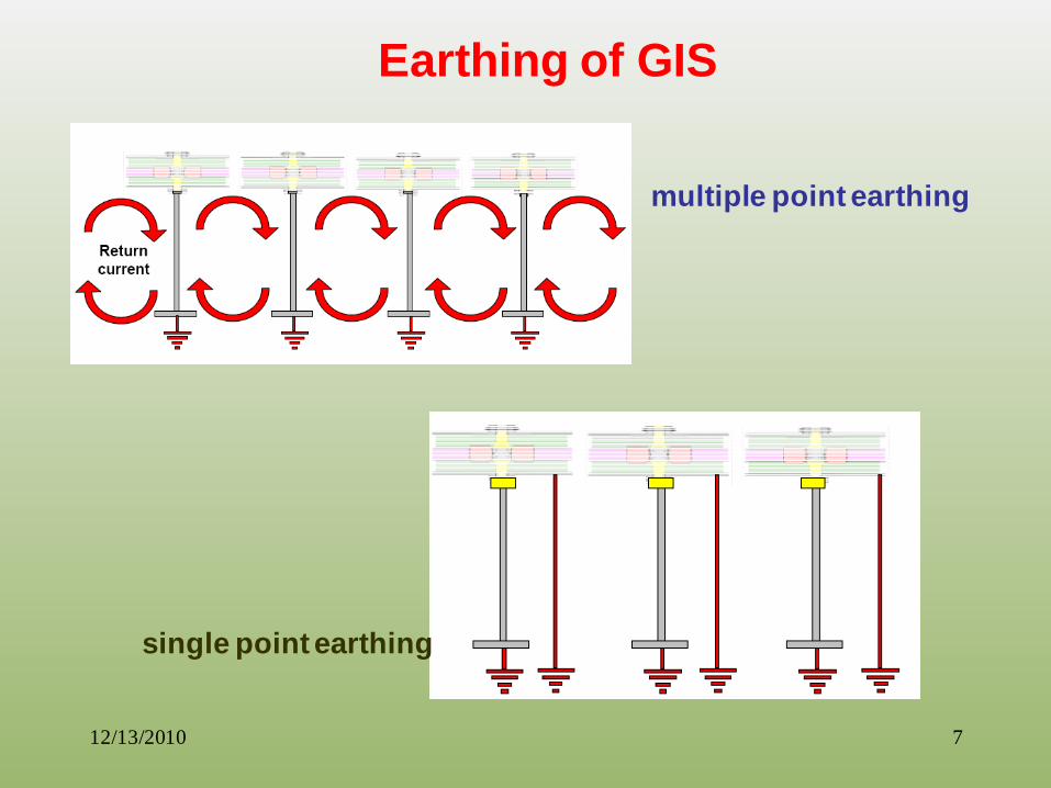
Earthing of GIS
single point earthing
multiple point earthing

12/13/2010 8
Earthing of GIS
1. Return
Conductors
2. Earthing
conductors
3. Return and
Earthing
Conductors
4. GIS earthing
mat.
12/13/2010 9
Earthing of GIS
Multipoint Earthing is advantageous than single point
earthing because of the following:
• Reliability of grounding
• Low magnetic field intensity outside the enclosure
• VFT related Flashovers Can be controlled.
12/13/2010 10
Earthing of GIS
In Multipoint Earthing the following aspects are Important:
1. Only small portion of the return current flow through the
earthing conductors.
2. The current induced in the enclosure could be up to 90 to
95 % of the rated current.
3.To avoid excessive currents in grounding grid (earthing
net) the enclosures are connected by inter-phase shunts.
4. Due to multiple eathing connections loops are formed
which carry very high induced currents due to strong
electromagnetic field coupling and low impedances.

VFTO LEVELS?
VFTO – SECONDARY BREAKDOWN
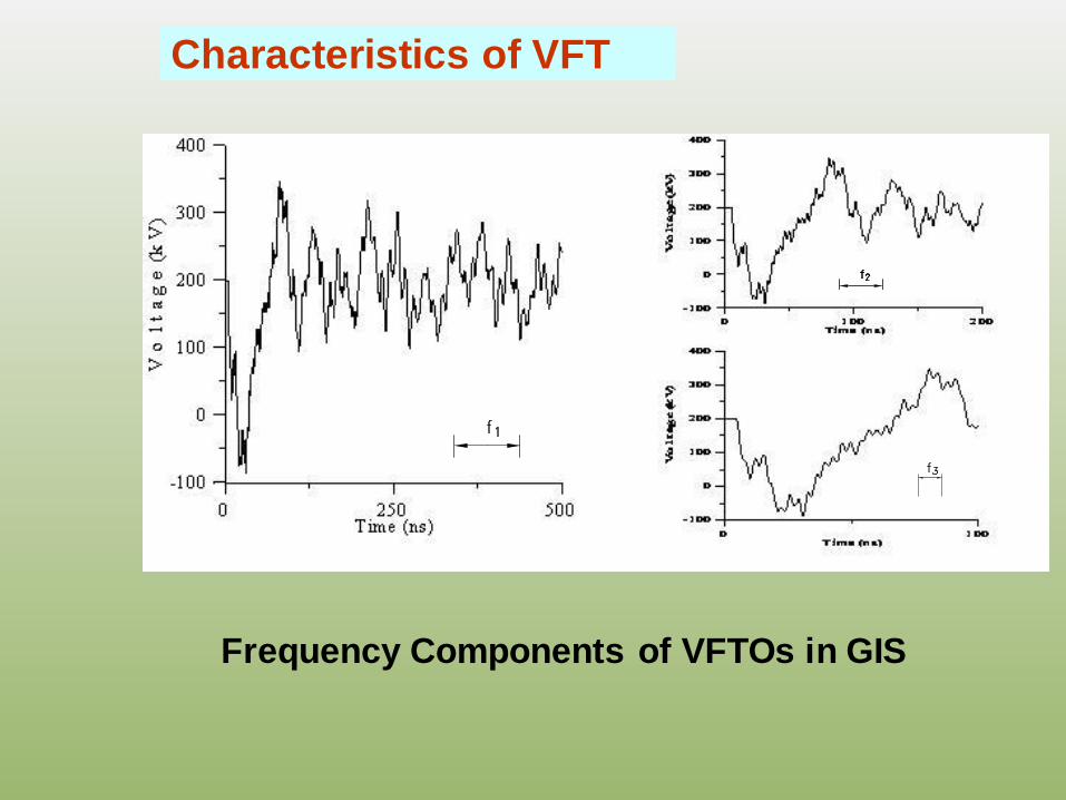
Characteristics of VFT
Frequency Components of VFTOs in GIS
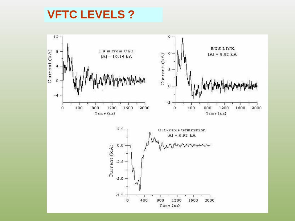
VFTC LEVELS ?
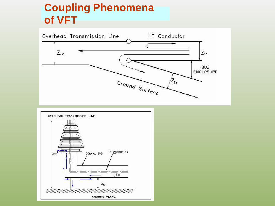
Coupling Phenomena of VFT
Why TEV IS A CONCERN?
Internal voltage collapse produces travelling waves,
in both directions, from the point of breakdown.
Such transients are often called VFTO (very fast
transient over voltages). At the points of
discontinuity (changes in surge impedance) these
VFTO waves get reflected and refracted. Such
transitions can be modeled as junctions of
transmission lines.
Being high freq. transients, the currents are confined
to the “skin depth” of the coaxial conductors.
Why TEV IS A CONCERN?
The very fast transient over voltages and the
associated transient currents generated in gas
insulated section propagates partly to the overhead
transmission line and partly to the exterior surface of
the bus section enclosure.
Typical impedance junctions are air/SF6 bushing,
GIS/cable connections, ground leads connecting the
enclosure to the earthing grid/mat/plate, or a ZnO
arrester. Out of these two, gas-to-air bushing is the
most significant one.
The transient voltages that appear on the exterior
surface of the enclosure during switching operations or
earth faults is known as Transient Enclosure voltages
(TEV) or Transient Ground Potential Rise (TGPR).
Why TEV IS A CONCERN?
TEV or TGPR can be a very serious EMC and personnel
safety problem. Voltage rise on grounded shields of
several kV at distances up to several km have been
observed in early days.
Such transient voltages on the “grounded” enclosure
arise from an internal collapse of voltage in the SF6 gas,
internal re-strikes across circuit breaker or disconnect
switch contacts, or flashover of external insulation
close to GIS, e.g., and air-SF6 bushing.
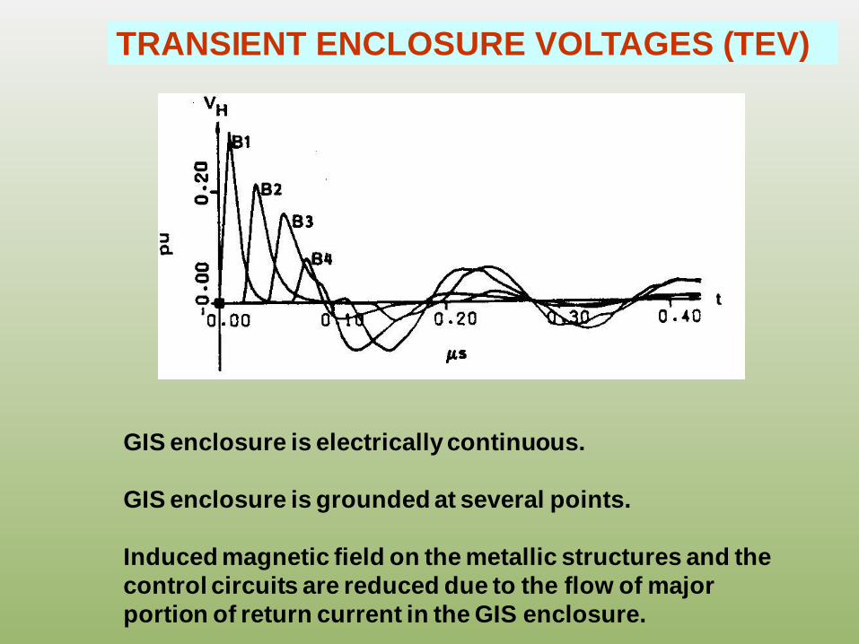
TRANSIENT ENCLOSURE VOLTAGES (TEV)
GIS enclosure is electrically continuous.
GIS enclosure is grounded at several points.
Induced magnetic field on the metallic structures and the
control circuits are reduced due to the flow of major
portion of return current in the GIS enclosure.
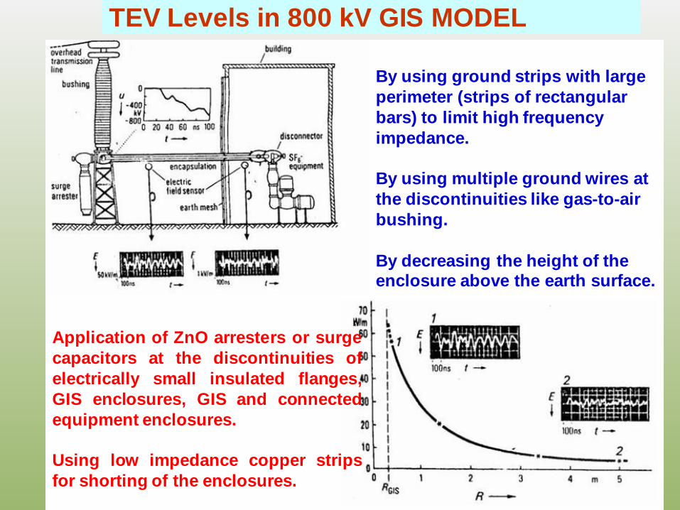
TEV Levels in 800 kV GIS MODEL
Application of ZnO arresters or surge
capacitors at the discontinuities of
electrically small insulated flanges,
GIS enclosures, GIS and connected
equipment enclosures.
Using low impedance copper strips
for shorting of the enclosures.
By using ground strips with large
perimeter (strips of rectangular
bars) to limit high frequency
impedance.
By using multiple ground wires at
the discontinuities like gas-to-air
bushing.
By decreasing the height of the enclosure above the earth surface.
• Support spacer flanges can also act as sites for reflections.
• Internal breakdown give a step voltage
rise-time, dependent on gas pressure of
SF6,
Tr(min) ≈ (1……1.5) ns
p
where, p is in mPa.
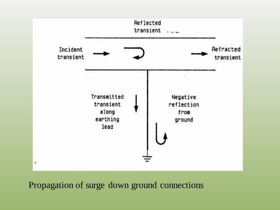
Propagation of surge down ground connections
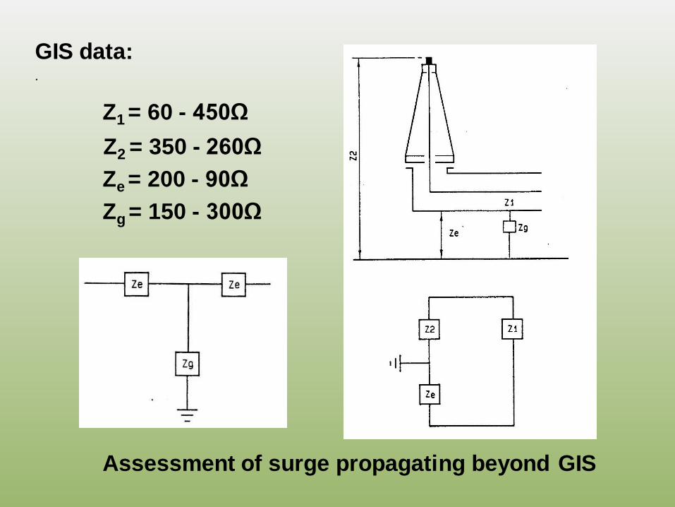
GIS data:.
Z1 = 60 - 450Ω
Z2 = 350 - 260Ω
Ze = 200 - 90Ω
Zg = 150 - 300Ω
Assessment of surge propagating beyond GIS
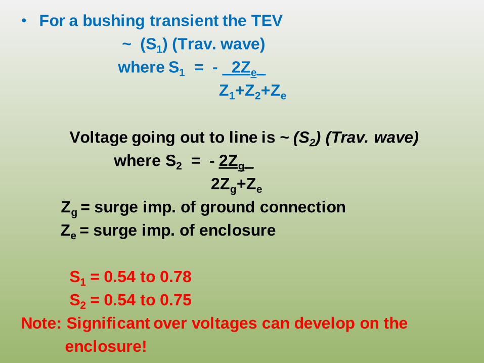
• For a bushing transient the TEV
~ (S1) (Trav. wave)
where S1 = - _2Ze_
Z1+Z2+Ze
Voltage going out to line is ~ (S2) (Trav. wave)
where S2 = - 2Zg_
2Zg+Ze
Zg = surge imp. of ground connection
Ze = surge imp. of enclosure
S1 = 0.54 to 0.78
S2 = 0.54 to 0.75
Note: Significant over voltages can develop on the
enclosure!
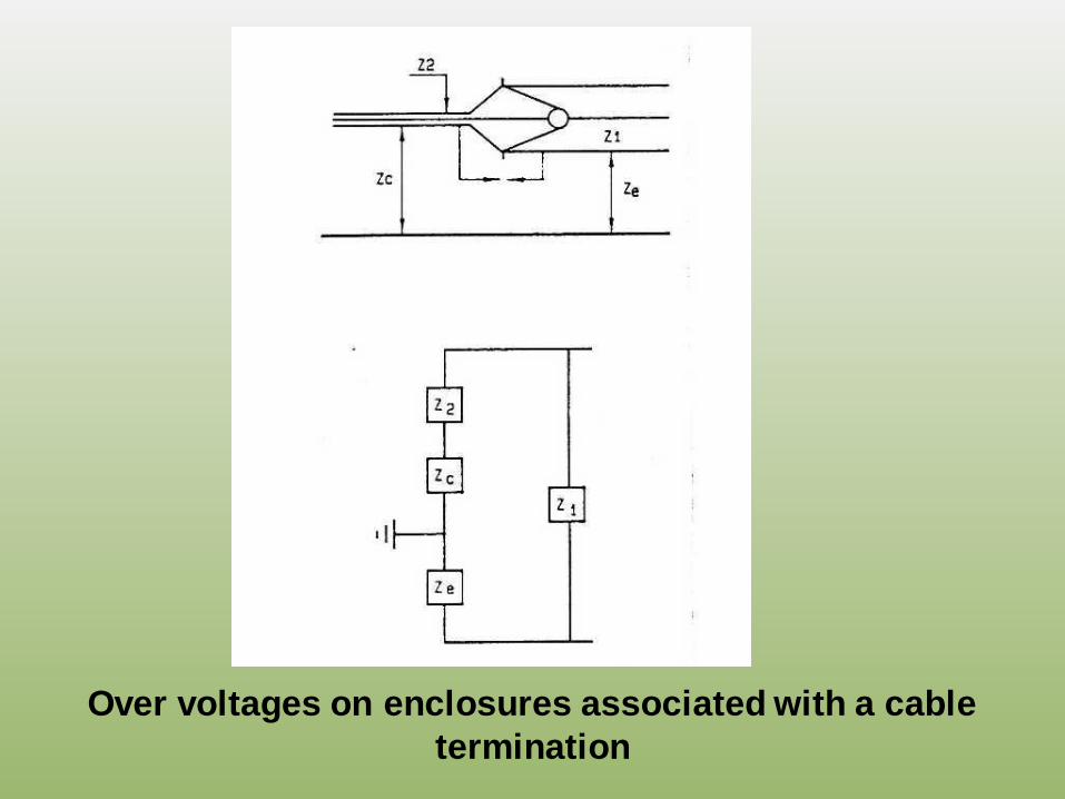
Over voltages on enclosures associated with a cable
termination
Transient Ground-Rises in GIS
(For earthing practices in GIS installation see: W G
21.03 Rep. in Electra, No. 151, Dec., 1993, PP. 31-
52)
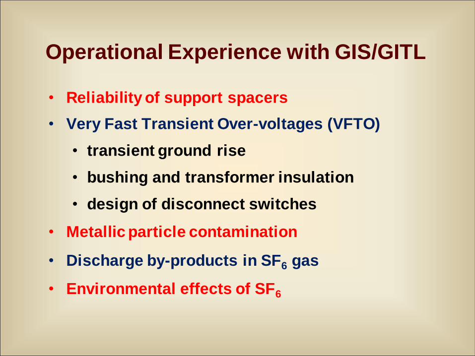
Operational Experience with GIS/GITL
• Reliability of support spacers
• Very Fast Transient Over-voltages (VFTO)
• transient ground rise
• bushing and transformer insulation
• design of disconnect switches
• Metallic particle contamination
• Discharge by-products in SF6 gas
• Environmental effects of SF6
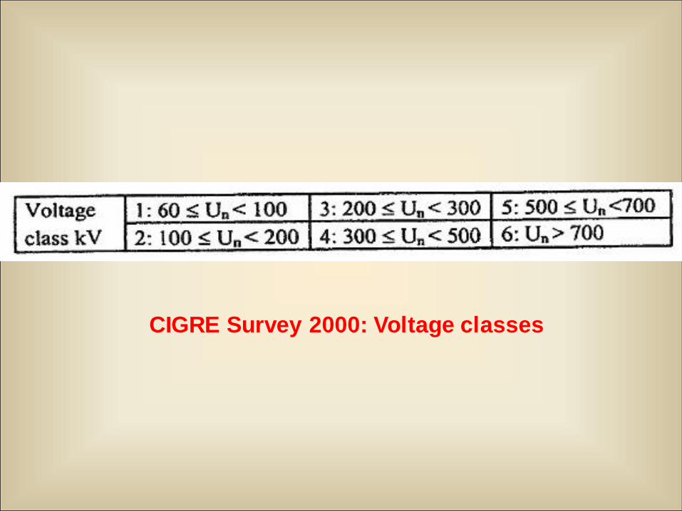
CIGRE Survey 2000: Voltage classes
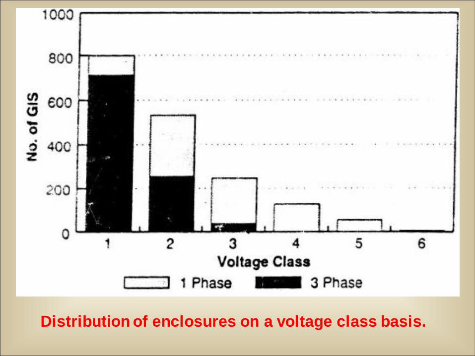
Distribution of enclosures on a voltage class basis.
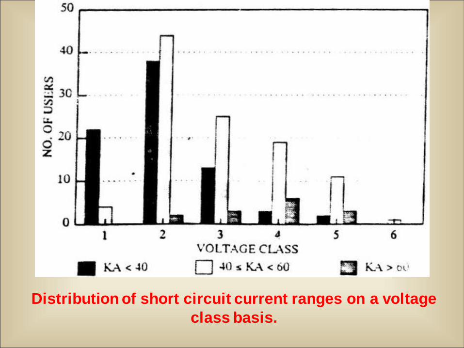
Distribution of short circuit current ranges on a voltage
class basis.
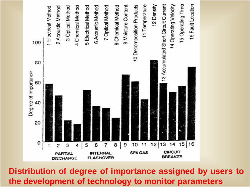
Distribution of degree of importance assigned by users to
the development of technology to monitor parameters

Users’ opinion on continuous vs. periodic
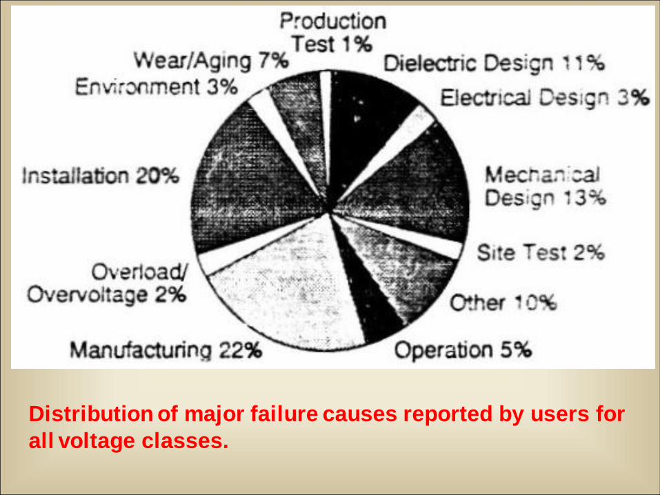
Distribution of major failure causes reported by users for
all voltage classes.
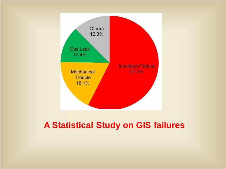
A Statistical Study on GIS failures
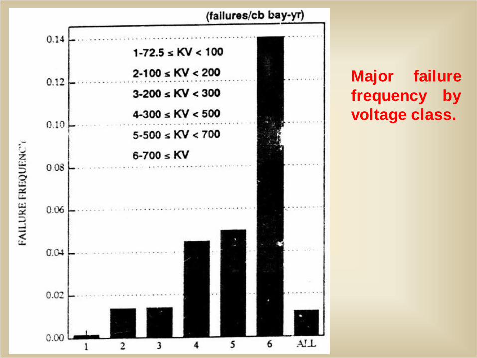
Major failure
frequency by
voltage class.
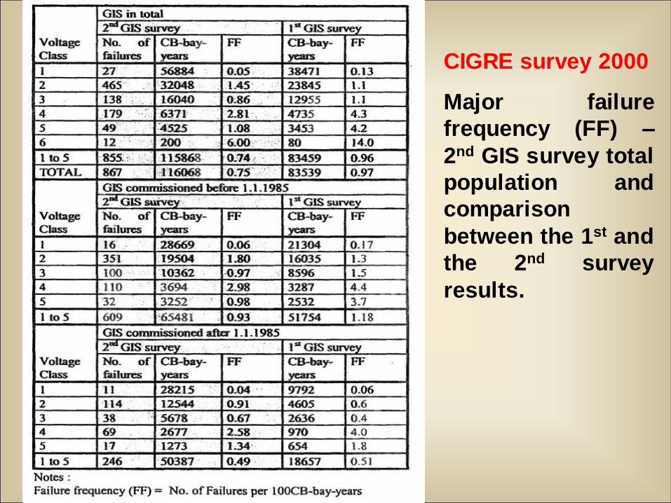
CIGRE survey 2000
Major failure
frequency (FF) –
2nd GIS survey total
population and
comparison
between the 1st and
the 2nd survey
results.
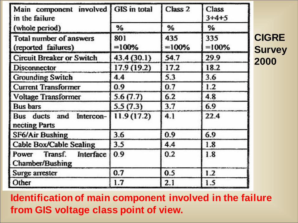
Identification of main component involved in the failure
from GIS voltage class point of view.
CIGRE
Survey
2000
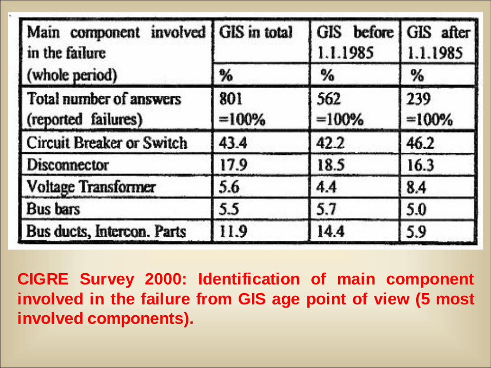
CIGRE Survey 2000: Identification of main component
involved in the failure from GIS age point of view (5 most
involved components).
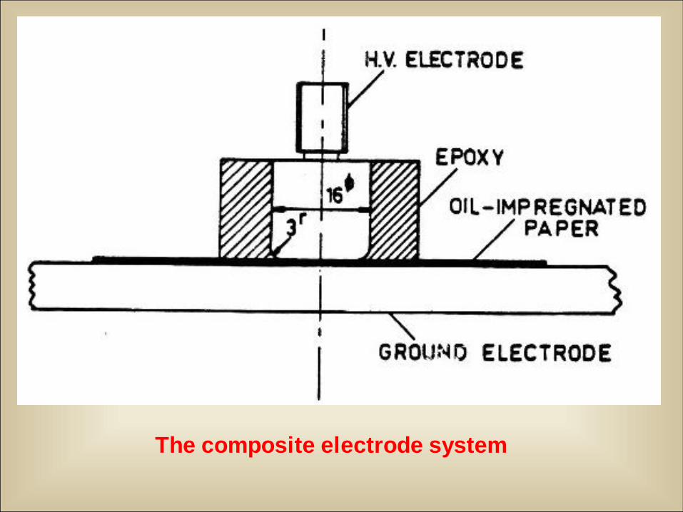
The composite electrode system
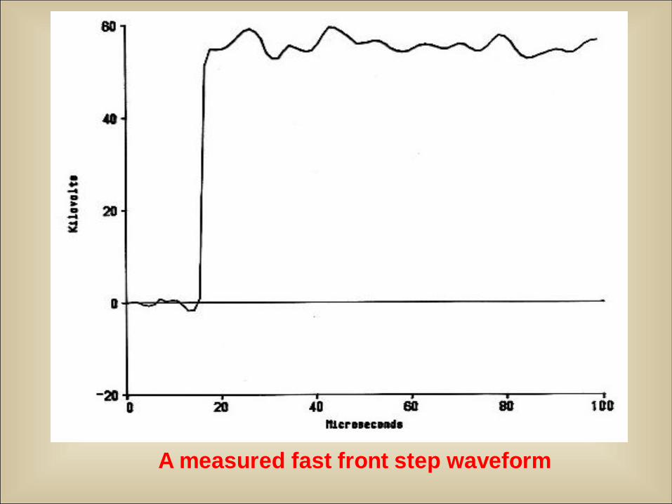
A measured fast front step waveform
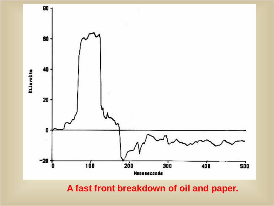
A fast front breakdown of oil and paper.
12/13/2010 17
Operation of 145 kV GIS at
APTRANSCo
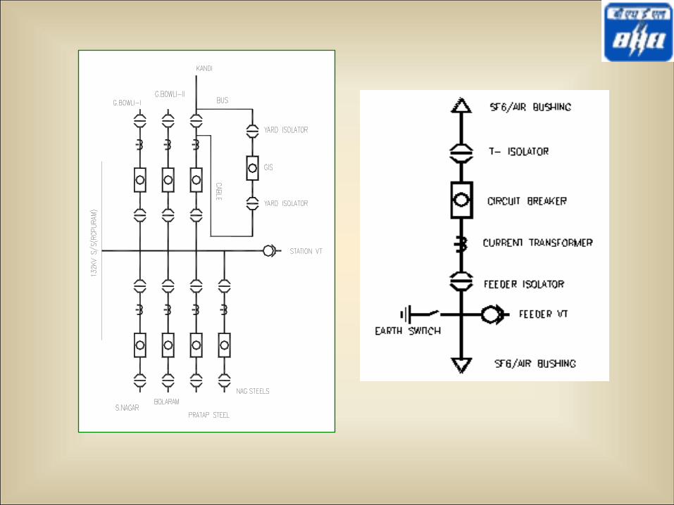
12/13/2010 19
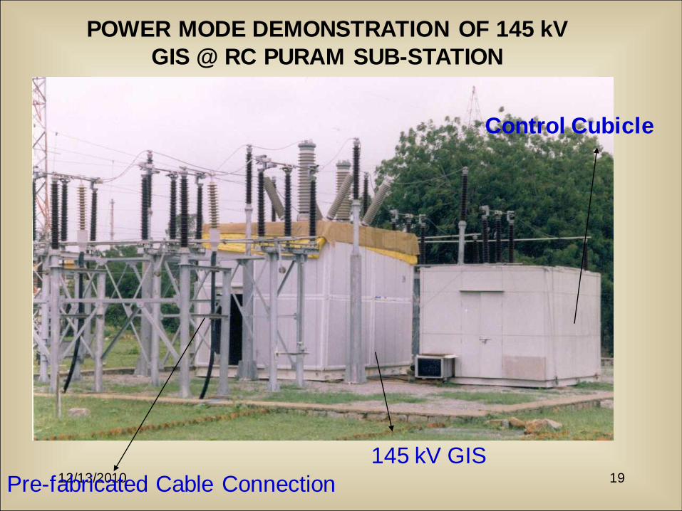
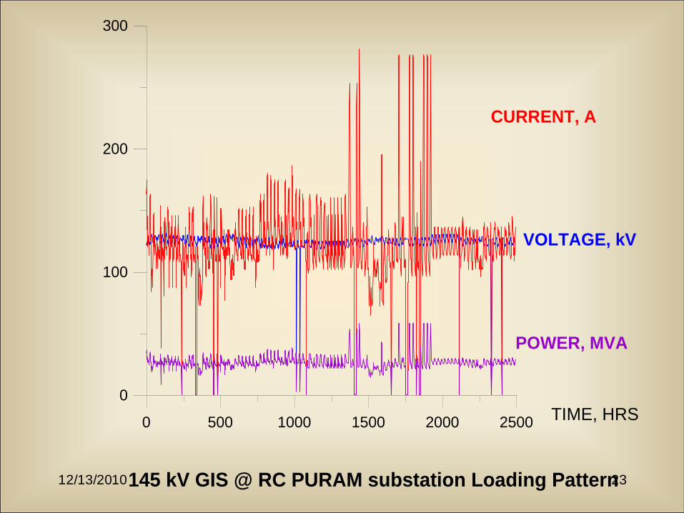
POWER MODE DEMONSTRATION OF 145 kV
GIS @ RC PURAM SUB-STATION
Pre-fabricated Cable Connection
145 kV GIS
Control Cubicle
12/13/2010 20
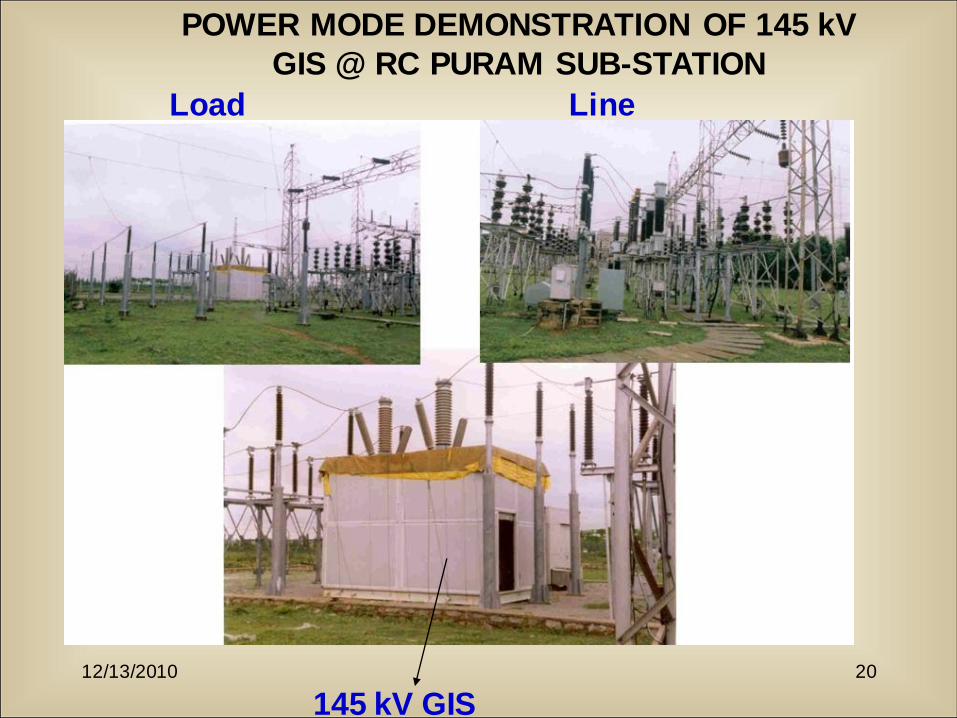
POWER MODE DEMONSTRATION OF 145 kV
GIS @ RC PURAM SUB-STATION
145 kV GIS
Load Line
12/13/2010 21
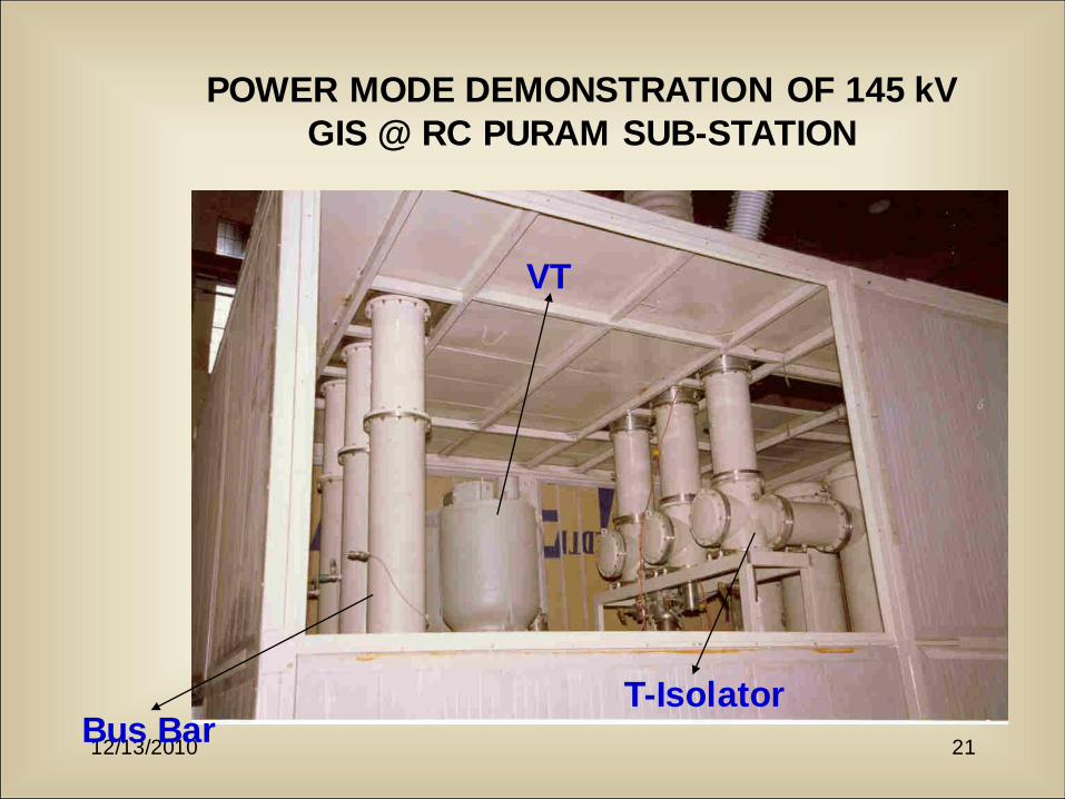
POWER MODE DEMONSTRATION OF 145 kV
GIS @ RC PURAM SUB-STATION
Bus BarT-Isolator
VT

12/13/2010 22
145 kV GIS
12/13/2010 23
0 500 1000 1500 2000 2500
0
100
200
300
TIME, HRS
CURRENT, A
VOLTAGE, kV
POWER, MVA
145 kV GIS @ RC PURAM substation Loading Pattern
Environmental Concerns with SF6
Usage and SF6-N2 Mixtures
Dr. M. Mohana Rao
BHEL Corporate R&D
Hyderabad
E-mail: [email protected]
Arcing and Discharges in GIS SF6
Insulation and Handling of By-
products
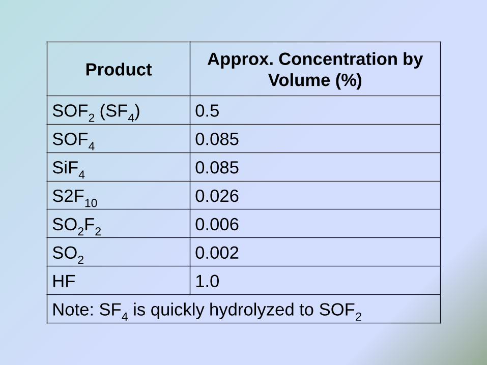
ProductApprox. Concentration by
Volume (%)
SOF2 (SF4) 0.5
SOF4 0.085
SiF4 0.085
S2F10 0.026
SO2F2 0.006
SO2 0.002
HF 1.0
Note: SF4 is quickly hydrolyzed to SOF2
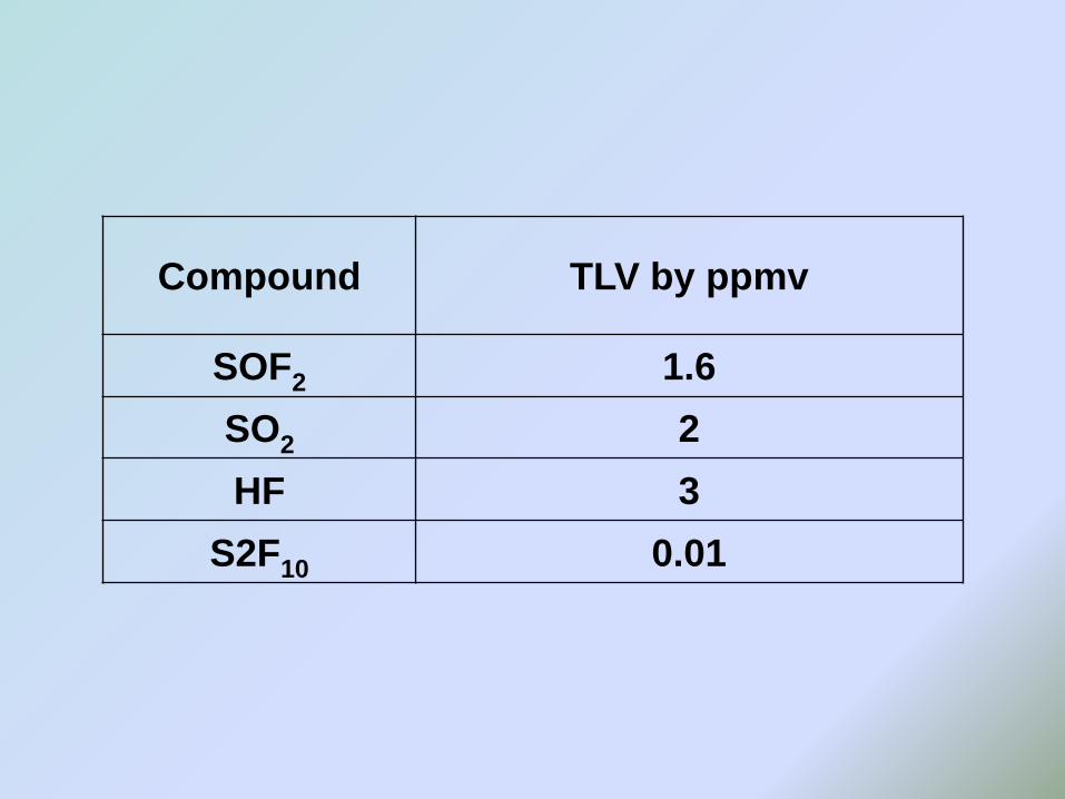
Compound TLV by ppmv
SOF2 1.6
SO2 2
HF 3
S2F10 0.01
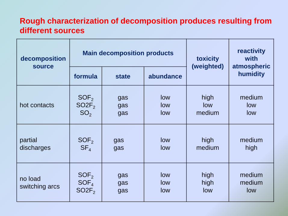
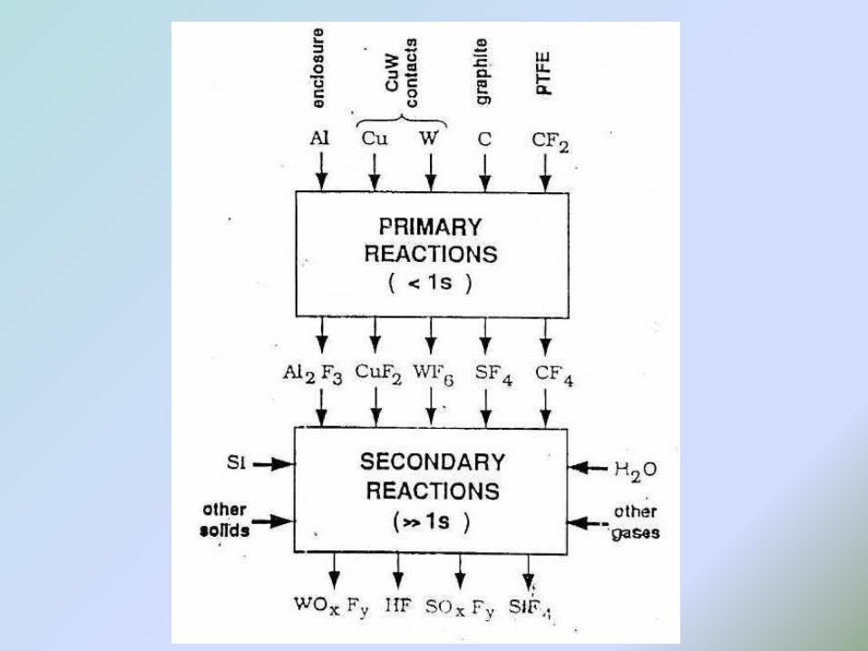
decomposition
source
Main decomposition productstoxicity
(weighted)
reactivity
with
atmospheric
humidityformula state abundance
hot contacts
SOF2
SO2F2
SO2
gas
gas
gas
low
low
low
high
low
medium
medium
low
low
partial
discharges
SOF2
SF4
gas
gas
low
low
high
medium
medium
high
no load
switching arcs
SOF2
SOF4
SO2F2
gas
gas
gas
low
low
low
high
high
low
medium
medium
low
Rough characterization of decomposition produces resulting from
different sources
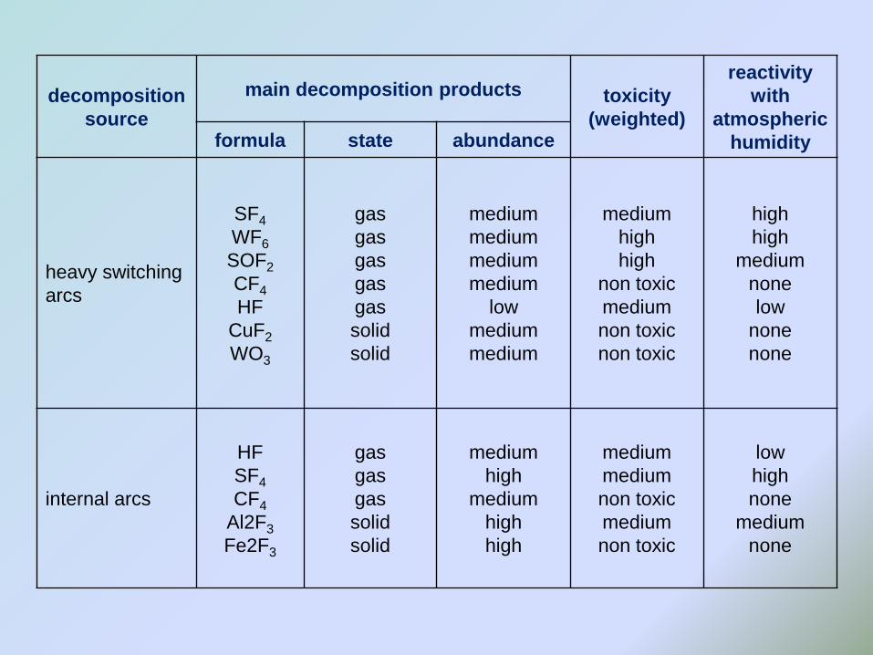
decomposition
source
main decomposition products toxicity
(weighted)
reactivity
with
atmospheric
humidityformula state abundance
heavy switching
arcs
SF4
WF6
SOF2
CF4
HF
CuF2
WO3
gas
gas
gas
gas
gas
solid
solid
medium
medium
medium
medium
low
medium
medium
medium
high
high
non toxic
medium
non toxic
non toxic
high
high
medium
none
low
none
none
internal arcs
HF
SF4
CF4
Al2F3
Fe2F3
gas
gas
gas
solid
solid
medium
high
medium
high
high
medium
medium
non toxic
medium
non toxic
low
high
none
medium
none
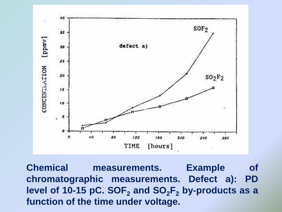
Chemical measurements. Example of
chromatographic measurements. Defect a): PD
level of 10-15 pC. SOF2 and SO2F2 by-products as a
function of the time under voltage.
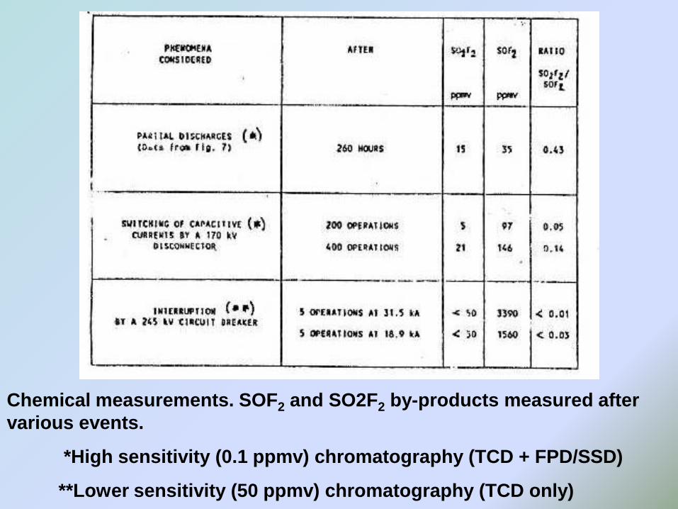
Chemical measurements. SOF2 and SO2F2 by-products measured after
various events.
*High sensitivity (0.1 ppmv) chromatography (TCD + FPD/SSD)
**Lower sensitivity (50 ppmv) chromatography (TCD only)
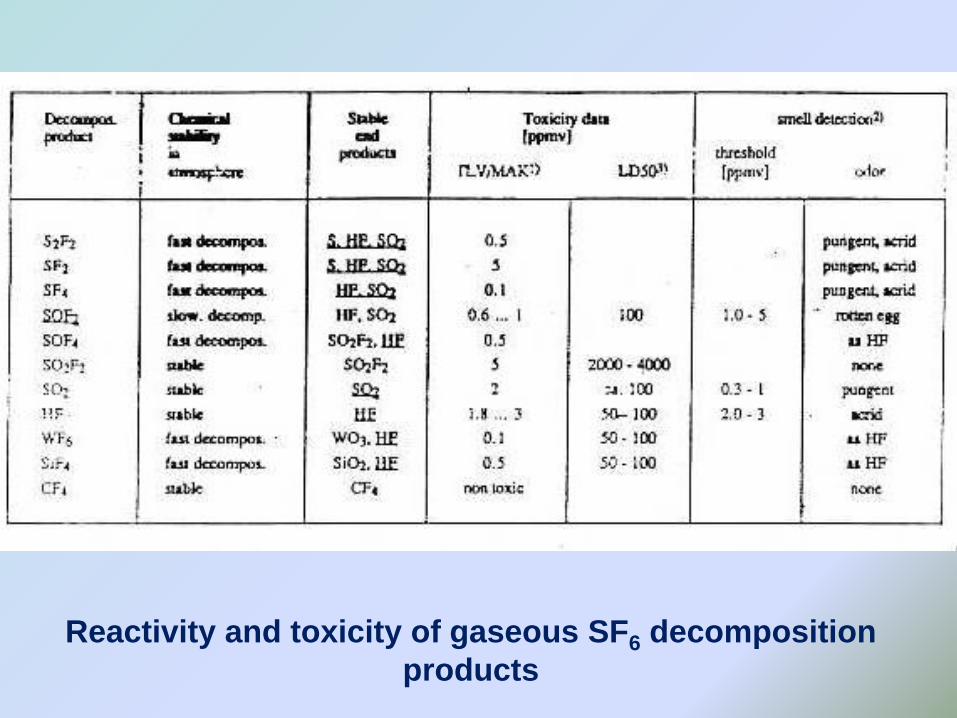
Reactivity and toxicity of gaseous SF6 decomposition
products
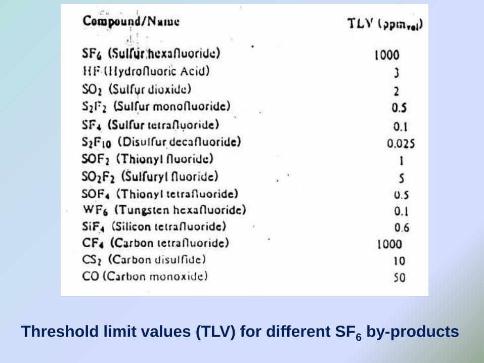
Threshold limit values (TLV) for different SF6 by-products
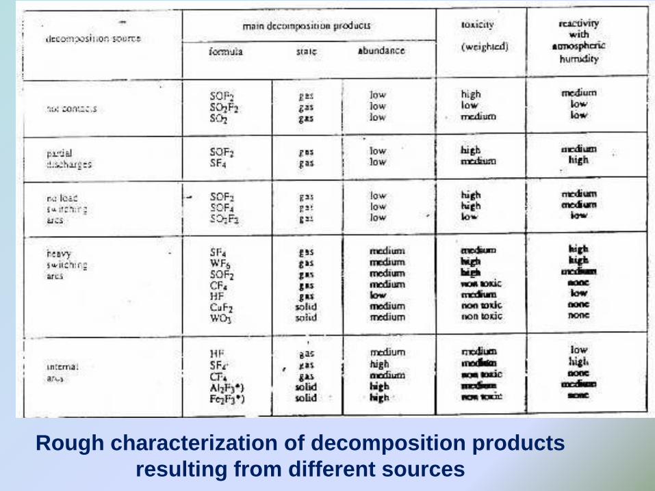
Rough characterization of decomposition products
resulting from different sources
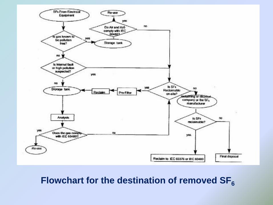
Flowchart for the destination of removed SF6
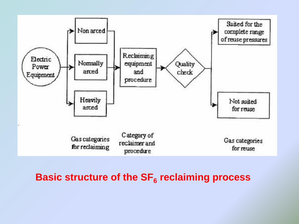
Basic structure of the SF6 reclaiming process
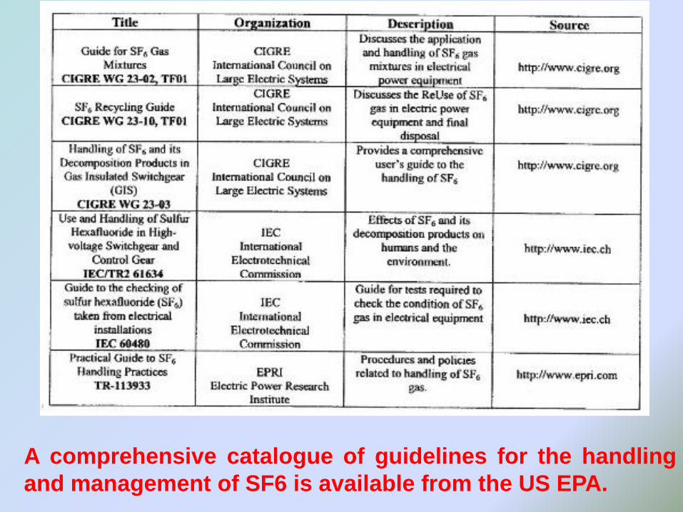
A comprehensive catalogue of guidelines for the handling
and management of SF6 is available from the US EPA.
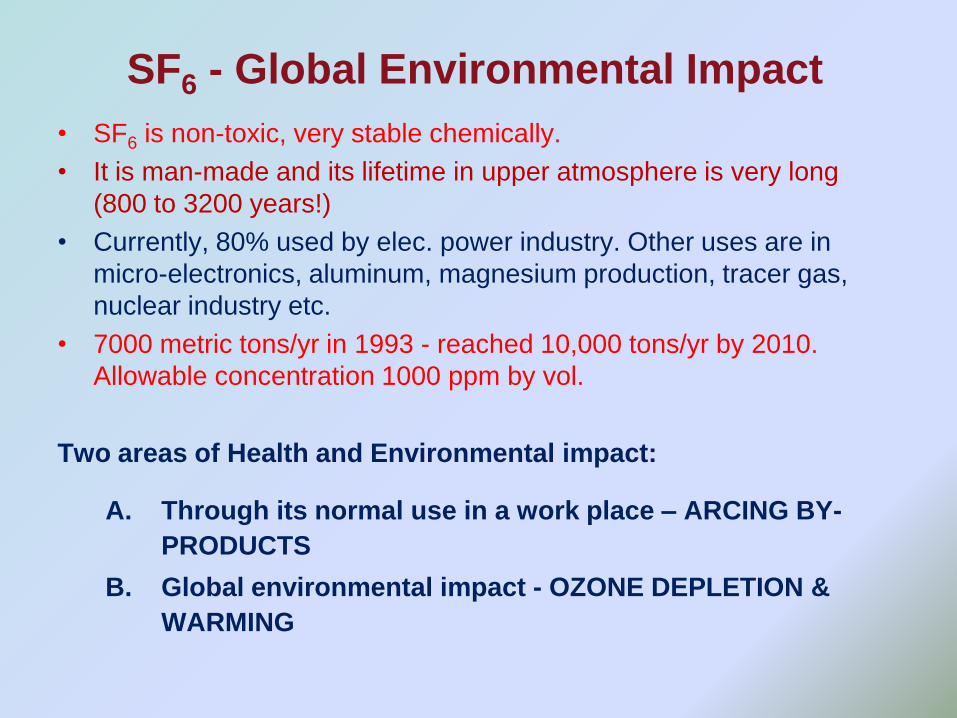
SF6 - Global Environmental Impact
• SF6 is non-toxic, very stable chemically.
• It is man-made and its lifetime in upper atmosphere is very long
(800 to 3200 years!)
• Currently, 80% used by elec. power industry. Other uses are in
micro-electronics, aluminum, magnesium production, tracer gas,
nuclear industry etc.
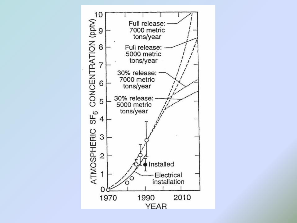
• 7000 metric tons/yr in 1993 - reached 10,000 tons/yr by 2010.
Allowable concentration 1000 ppm by vol.
Two areas of Health and Environmental impact:
A. Through its normal use in a work place – ARCING BY-
PRODUCTS
B. Global environmental impact - OZONE DEPLETION &
WARMING
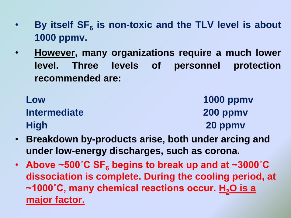
• By itself SF6 is non-toxic and the TLV level is about
1000 ppmv.
• However, many organizations require a much lower
level. Three levels of personnel protection
recommended are:
Low 1000 ppmv
Intermediate 200 ppmv
High 20 ppmv
• Breakdown by-products arise, both under arcing and
under low-energy discharges, such as corona.
• Above ~500˚C SF6 begins to break up and at ~3000˚C
dissociation is complete. During the cooling period, at
~1000˚C, many chemical reactions occur. H2O is a
major factor.
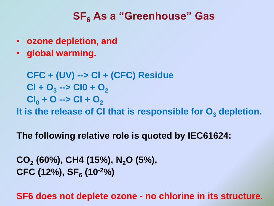
SF6 As a “Greenhouse” Gas
• ozone depletion, and
• global warming.
CFC + (UV) --> Cl + (CFC) Residue
Cl + O3 --> CI0 + O2
Cl0 + O --> Cl + O2
It is the release of Cl that is responsible for O3 depletion.
The following relative role is quoted by IEC61624:
CO2 (60%), CH4 (15%), N2O (5%),
CFC (12%), SF6 (10-2%)
SF6 does not deplete ozone - no chlorine in its structure.
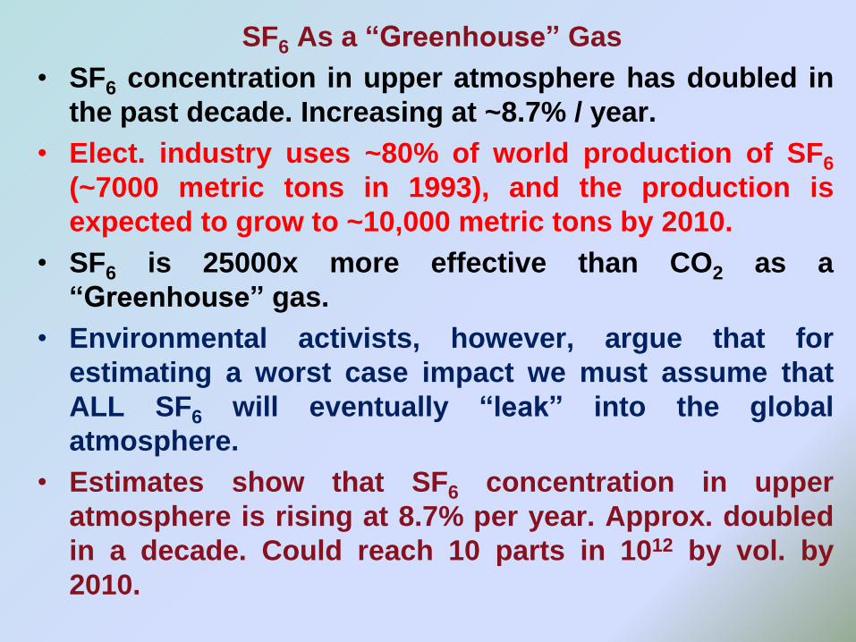
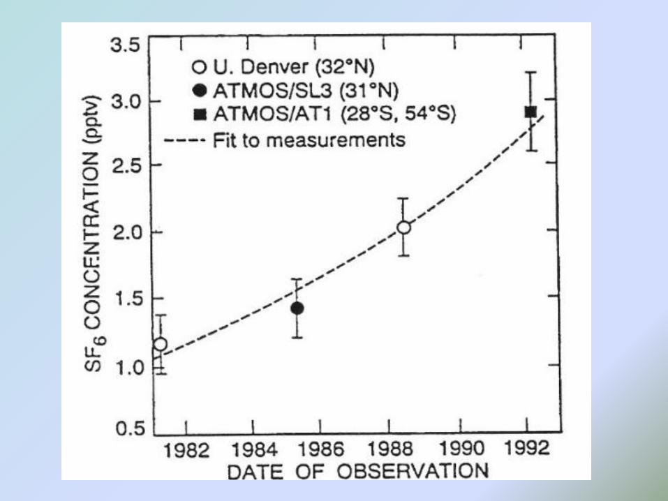
SF6 As a “Greenhouse” Gas
• SF6 concentration in upper atmosphere has doubled in
the past decade. Increasing at ~8.7% / year.
• Elect. industry uses ~80% of world production of SF6
(~7000 metric tons in 1993), and the production is
expected to grow to ~10,000 metric tons by 2010.
• SF6 is 25000x more effective than CO2 as a
“Greenhouse” gas.
• Environmental activists, however, argue that for
estimating a worst case impact we must assume that
ALL SF6 will eventually “leak” into the global
atmosphere.
• Estimates show that SF6 concentration in upper
atmosphere is rising at 8.7% per year. Approx. doubled
in a decade. Could reach 10 parts in 1012 by vol. by
2010.
SF6 As a “Greenhouse” Gas
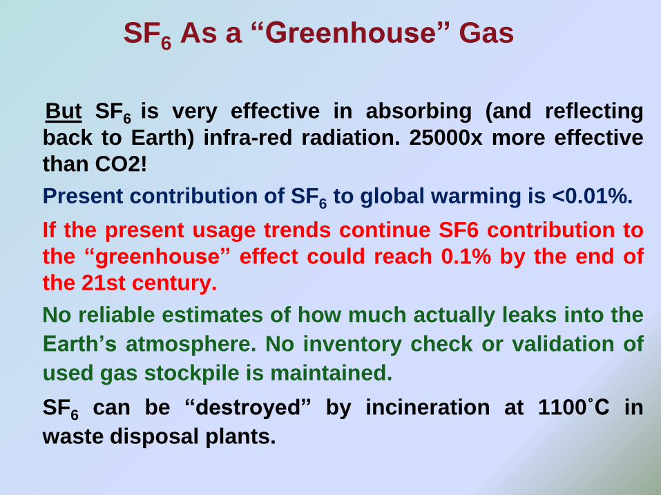
But SF6 is very effective in absorbing (and reflecting
back to Earth) infra-red radiation. 25000x more effective
than CO2!
Present contribution of SF6 to global warming is <0.01%.
If the present usage trends continue SF6 contribution to
the “greenhouse” effect could reach 0.1% by the end of
the 21st century.
No reliable estimates of how much actually leaks into the
Earth’s atmosphere. No inventory check or validation of
used gas stockpile is maintained.
SF6 can be “destroyed” by incineration at 1100˚C in
waste disposal plants.
SF6 As a “Greenhouse” Gas
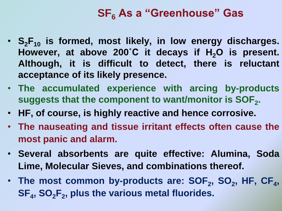
• S2F10 is formed, most likely, in low energy discharges.
However, at above 200˚C it decays if H2O is present.
Although, it is difficult to detect, there is reluctant
acceptance of its likely presence.
• The accumulated experience with arcing by-products
suggests that the component to want/monitor is SOF2.
• HF, of course, is highly reactive and hence corrosive.
• The nauseating and tissue irritant effects often cause the
most panic and alarm.
• Several absorbents are quite effective: Alumina, Soda
Lime, Molecular Sieves, and combinations thereof.
• The most common by-products are: SOF2, SO2, HF, CF4,
SF4, SO2F2, plus the various metal fluorides.
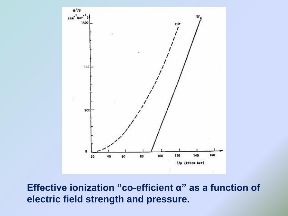
Effective ionization “co-efficient α” as a function of
electric field strength and pressure.
The table shows the values of relative electric strengths
measured at pressure indicated (mm Hg) relative to air at
the same pressure.
The measurements were made using two polished brass
spheres of diameter 1 inch contained in a glass cell which
could be evacuated. The spark gap was generally 0.015 to
0.020 inch. The apparatus was checked frequently by the
measurement of the relative electric strength of SF6. The
average value of this was 2.5.
Values of Relative Electric Strengths
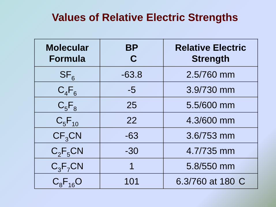
Molecular
Formula
BP
C
Relative Electric
Strength
SF6 -63.8 2.5/760 mm
C4F6 -5 3.9/730 mm
C5F8 25 5.5/600 mm
C5F10 22 4.3/600 mm
CF3CN -63 3.6/753 mm
C2F5CN -30 4.7/735 mm
C3F7CN 1 5.8/550 mm
C8F16O 101 6.3/760 at 180 C
Values of Relative Electric Strengths
Environmental Impact of SF6
• SF6 is a gas specifically mentioned in Kyoto
protocol. Search is on for a replacement gas or
gas mixture. 80% of SF6 manufactured is used by
the electrical industry. Leakage rates are <1% per
year. Equipment with 20% SF6 is on the market.
• So, there is concern in industry about the long-termprospects for its continued use in switchgear andGIS. Hence, the interest in mixtures.
• No other synthetic gas (fluoro-carbons) is better inits environmental impact.
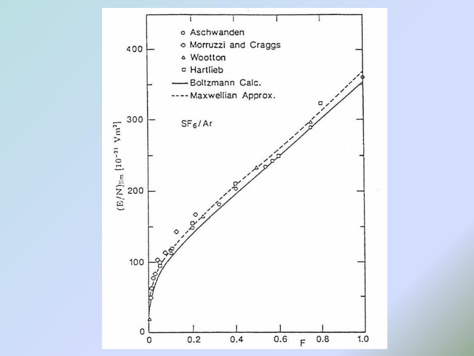
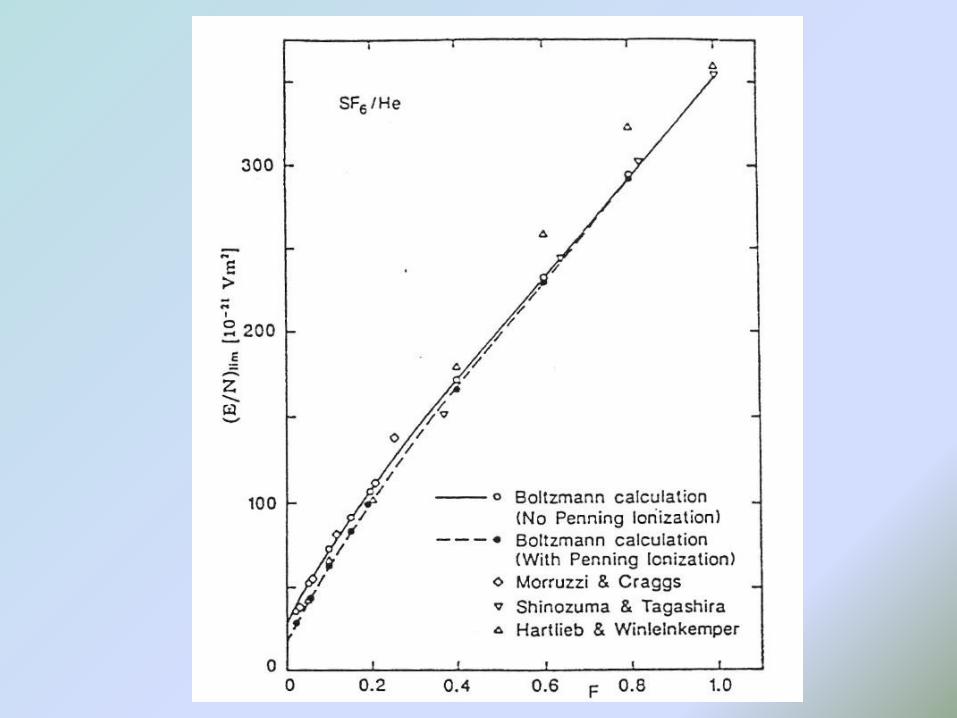
SF6/N2 Mixtures for GIS?
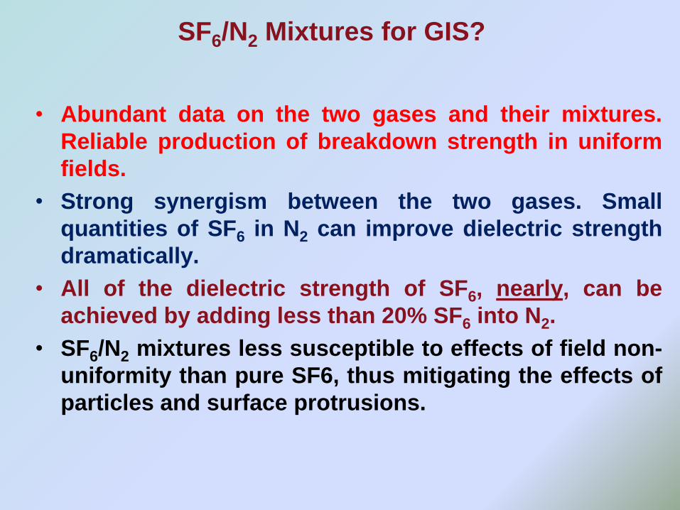
• Abundant data on the two gases and their mixtures.
Reliable production of breakdown strength in uniform
fields.
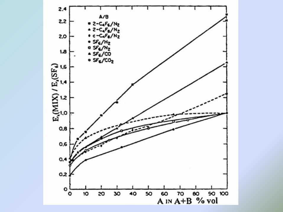
• Strong synergism between the two gases. Small
quantities of SF6 in N2 can improve dielectric strength
dramatically.
• All of the dielectric strength of SF6, nearly, can be
achieved by adding less than 20% SF6 into N2.
• SF6/N2 mixtures less susceptible to effects of field non-
uniformity than pure SF6, thus mitigating the effects of
particles and surface protrusions.
SF6/N2 Mixtures for GIS?
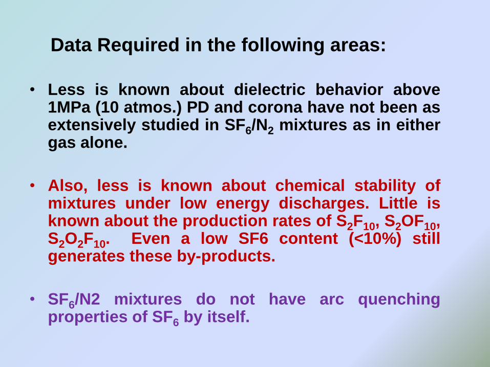
Data Required in the following areas:
• Less is known about dielectric behavior above1MPa (10 atmos.) PD and corona have not been asextensively studied in SF6/N2 mixtures as in eithergas alone.
• Also, less is known about chemical stability ofmixtures under low energy discharges. Little isknown about the production rates of S2F10, S2OF10,S2O2F10. Even a low SF6 content (<10%) stillgenerates these by-products.
• SF6/N2 mixtures do not have arc quenchingproperties of SF6 by itself.
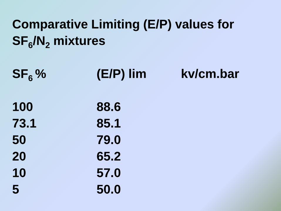
Comparative Limiting (E/P) values for
SF6/N2 mixtures
SF6 % (E/P) lim kv/cm.bar
100 88.6
73.1 85.1
50 79.0
20 65.2
10 57.0
5 50.0
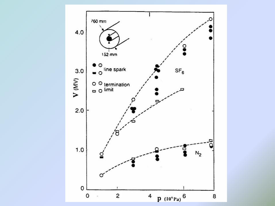
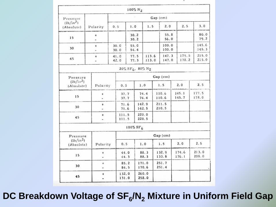
DC Breakdown Voltage of SF6/N2 Mixture in Uniform Field Gap
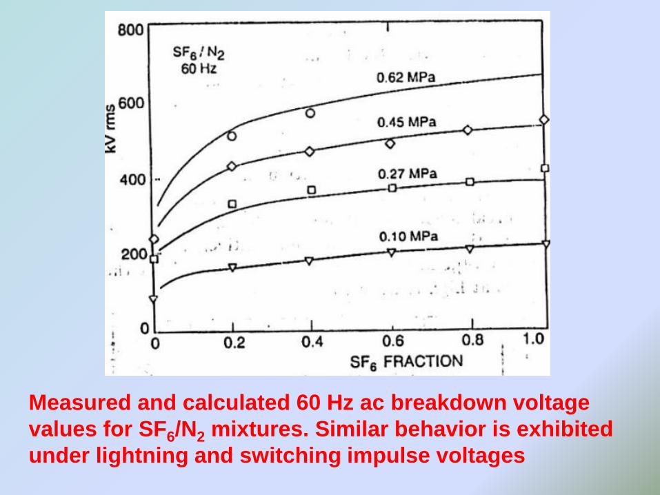
Measured and calculated 60 Hz ac breakdown voltage
values for SF6/N2 mixtures. Similar behavior is exhibited
under lightning and switching impulse voltages
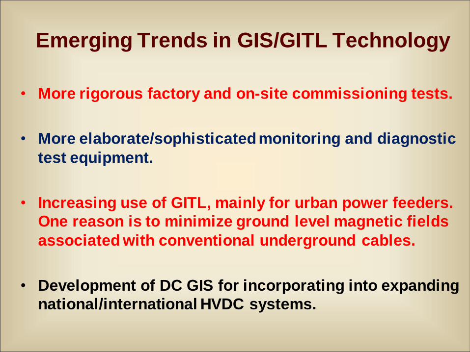
Emerging Trends in GIS/GITL Technology
• More rigorous factory and on-site commissioning tests.
• More elaborate/sophisticated monitoring and diagnostic
test equipment.
• Increasing use of GITL, mainly for urban power feeders.
One reason is to minimize ground level magnetic fields
associated with conventional underground cables.
• Development of DC GIS for incorporating into expanding
national/international HVDC systems.
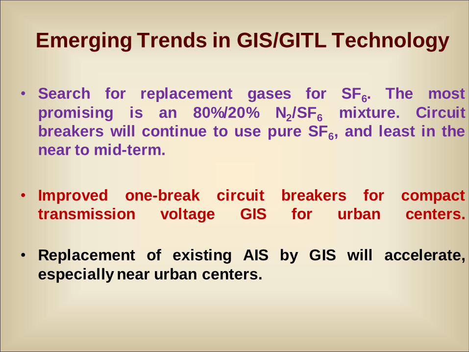
Emerging Trends in GIS/GITL Technology
• Search for replacement gases for SF6. The most
promising is an 80%/20% N2/SF6 mixture. Circuit
breakers will continue to use pure SF6, and least in the
near to mid-term.
• Improved one-break circuit breakers for compact
transmission voltage GIS for urban centers.
• Replacement of existing AIS by GIS will accelerate,
especially near urban centers.

New Developments
• UHF partial discharge detection
• HVDC GIS
• SF6/N2 mixtures
• Long GITL installations
• Compact substations
GIL/GIS Recent Development
• 70m long prototype for 400 kV system with SF6/N2 mixture
• Simulated 50 year life.
• Renewed interest in flexible lines. However, the biggest
challenge is the design of long 100 m sections. How to
mechanically support the conductor?
• Switching impulse tests for SF6/N2 mixture confirm
theoretical models.
• Recycling guidelines for SF6 and extracting SF6 from
SF6/N2 mixtures are now available.
• Three phase rectangular enclosures for 500 kV class have
been tested (~200 cm x 200 cm).
• Long-term field tests for GIL: minimum 1 year on a 100 m
section.
GIL/GIS Recent Development
• Comparison of aerial lines and GIL must take into account
the total life cycle costs, over 50 to 70 years.
• Combined voltage and current sensors.
• Highly integrated sub-station layout - a mixture of metal
clad and air-insulated technology.
• Very thick coatings on conductors.
• For DC GIS a conductive coating on spacers.
• Using an epoxy enclosure for GIL.
• Japanese ~3 km 275 kV GIL.
Recent Developments
• Leakage of SF6 <0.5% / yr
• Combined VT/CT
• Single-break CB for 550 kV
• 1100/1200 kV Prototype GIS
• Refurbishing of old GIS
• Replacement of AIS in urban areas
• Mechanical design to allow for SF6/N2 mixtures
• RE: Maintenance several categories may be defined and equipment classified, e.g.
• Routine inspection
• Preventive maintenance
• Repair maintenance
Corrective/special maintenance and component categories
may be:
Active or Passive Primary
Secondary equipment
• Most major utilities have codes of practice fordelivering maintenance services for GIS
• Life cycle costs have to be evaluated:
LCC = CI + CP + CR + CO + OC
CI: installation (equip. + land + comm. etc.)
CP: planned corrective
CR: repair
CO: operation
OC: outage
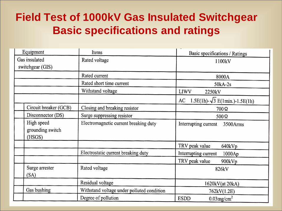
Field Test of 1000kV Gas Insulated Switchgear
Basic specifications and ratings
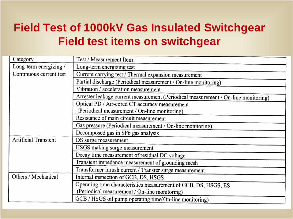
Field Test of 1000kV Gas Insulated Switchgear
Field test items on switchgear
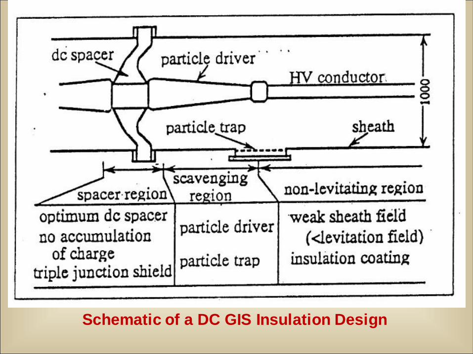
Schematic of a DC GIS Insulation Design
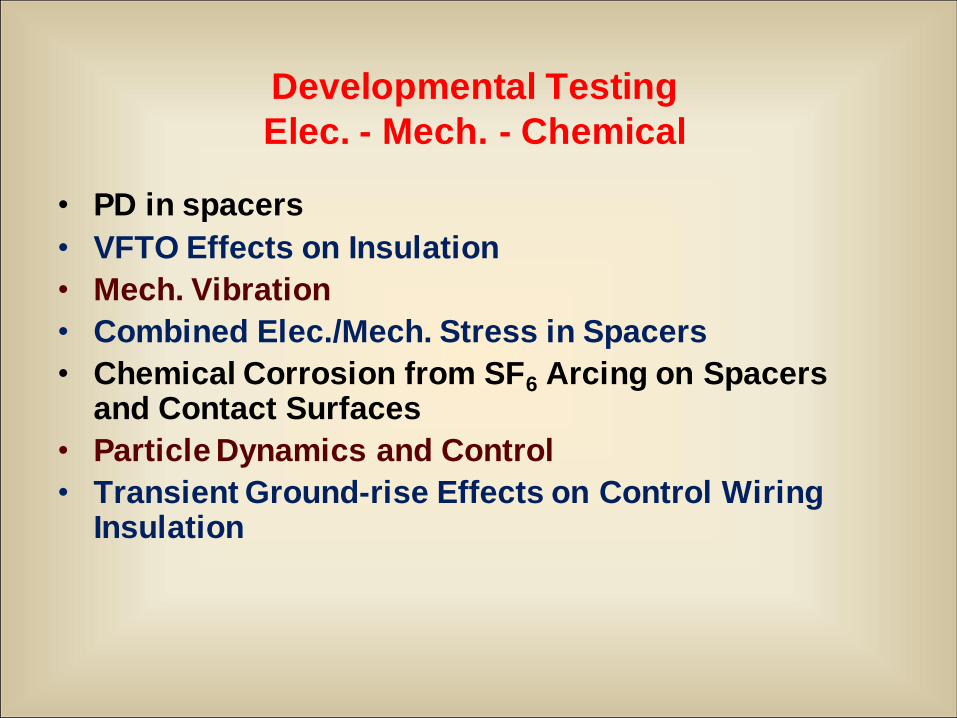
Developmental Testing
Elec. - Mech. - Chemical
• PD in spacers
• VFTO Effects on Insulation
• Mech. Vibration
• Combined Elec./Mech. Stress in Spacers
• Chemical Corrosion from SF6 Arcing on Spacers and Contact Surfaces
• Particle Dynamics and Control
• Transient Ground-rise Effects on Control Wiring Insulation
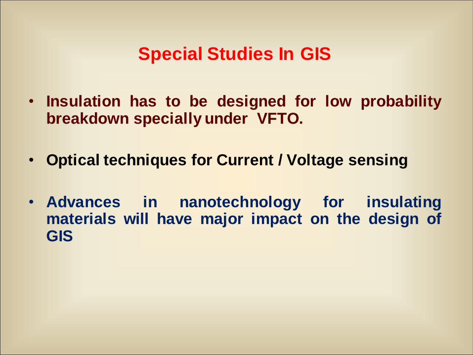
Special Studies In GIS
• Insulation has to be designed for low probabilitybreakdown specially under VFTO.
• Optical techniques for Current / Voltage sensing
• Advances in nanotechnology for insulatingmaterials will have major impact on the design ofGIS
12/13/2010 14
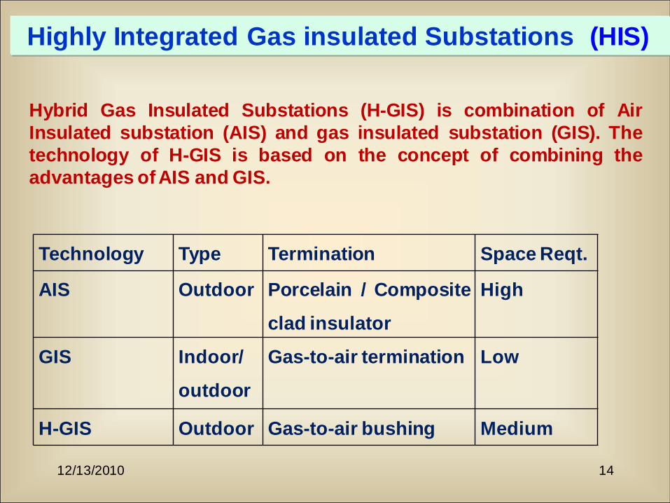
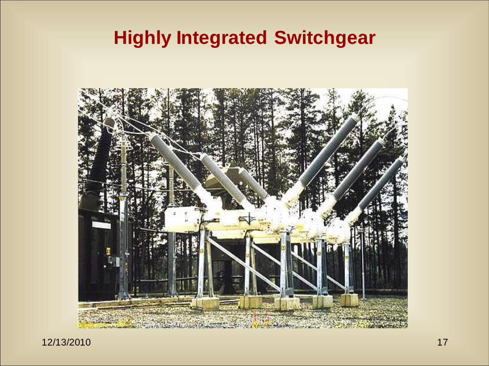
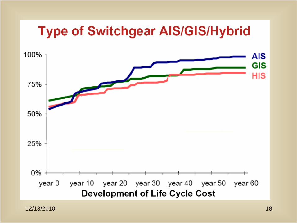
Highly Integrated Gas insulated Substations (HIS)
Hybrid Gas Insulated Substations (H-GIS) is combination of Air
Insulated substation (AIS) and gas insulated substation (GIS). The
technology of H-GIS is based on the concept of combining the
advantages of AIS and GIS.
Technology Type Termination Space Reqt.
AIS Outdoor Porcelain / Composite
clad insulator
High
GIS Indoor/
outdoor
Gas-to-air termination Low
H-GIS Outdoor Gas-to-air bushing Medium
12/13/2010 15
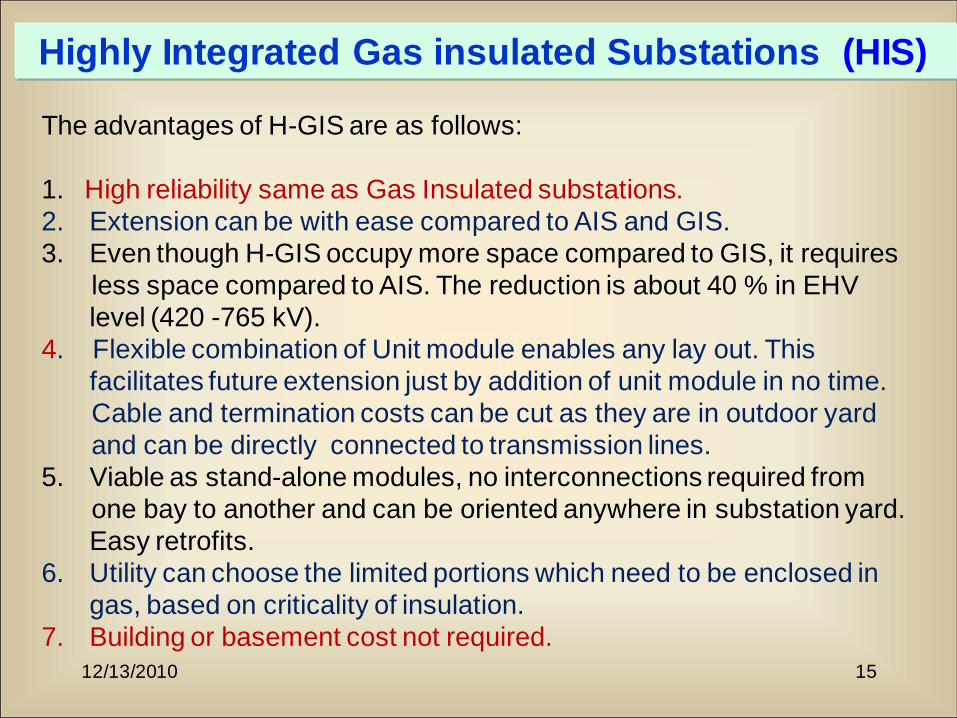
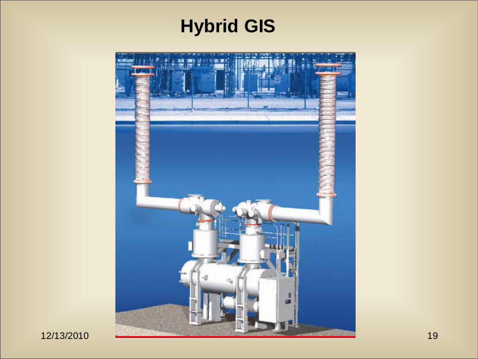
Highly Integrated Gas insulated Substations (HIS)
The advantages of H-GIS are as follows:
1. High reliability same as Gas Insulated substations.
2. Extension can be with ease compared to AIS and GIS.
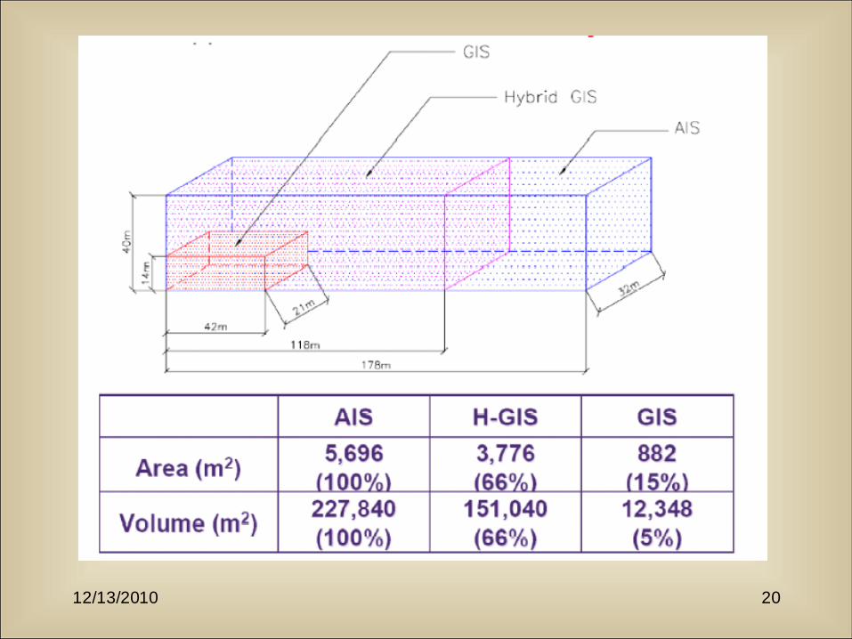
3. Even though H-GIS occupy more space compared to GIS, it requires
less space compared to AIS. The reduction is about 40 % in EHV
level (420 -765 kV).
4. Flexible combination of Unit module enables any lay out. This
facilitates future extension just by addition of unit module in no time.
Cable and termination costs can be cut as they are in outdoor yard
and can be directly connected to transmission lines.
5. Viable as stand-alone modules, no interconnections required from
one bay to another and can be oriented anywhere in substation yard.
Easy retrofits.
6. Utility can choose the limited portions which need to be enclosed in
gas, based on criticality of insulation.
7. Building or basement cost not required.

12/13/2010 16
Highly Integrated Gas insulated Substations (HIS)
12/13/2010 17
Highly Integrated Switchgear
12/13/2010 18
12/13/2010 19
Hybrid GIS
12/13/2010 20
12/13/2010 21
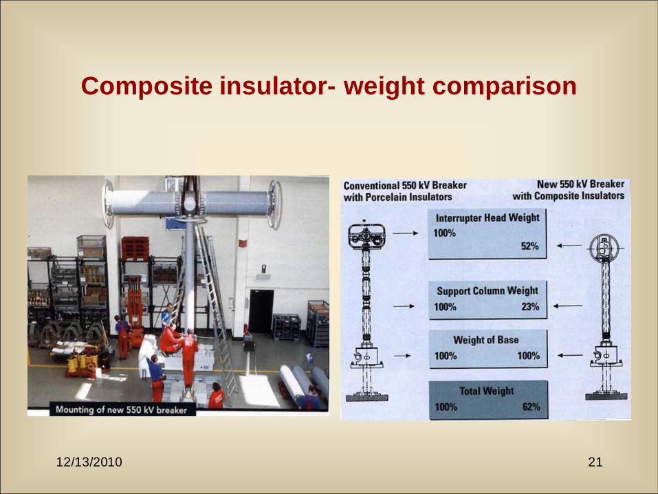
Composite insulator- weight comparison