Giovannini, D., Romero, J., Potoček, V., Ferenczi, G ...eprints.gla.ac.uk/102869/1/102869.pdf ·...
13
Giovannini, D., Romero, J., Potoček, V., Ferenczi, G., Speirits, F., Barnett, S. M., Faccio, D., and Padgett, M. J. (2015) Spatially structured photons that travel in free space slower than the speed of light. Science, 347(6224), pp. 857-860. Copyright © 2015 The Authors Version: Accepted http://eprints.gla.ac.uk/102869 Deposited on: 20 February 2015 Enlighten – Research publications by members of the University of Glasgow http://eprints.gla.ac.uk
Transcript of Giovannini, D., Romero, J., Potoček, V., Ferenczi, G ...eprints.gla.ac.uk/102869/1/102869.pdf ·...
Giovannini, D., Romero, J., Potoček, V., Ferenczi, G., Speirits, F., Barnett, S. M., Faccio, D., and Padgett, M. J. (2015) Spatially structured photons that travel in free space slower than the speed of light. Science, 347(6224), pp. 857-860.
Copyright © 2015 The Authors
Version: Accepted http://eprints.gla.ac.uk/102869 Deposited on: 20 February 2015
Enlighten – Research publications by members of the University of Glasgow http://eprints.gla.ac.uk
1
Spatially Structured Photons that Travel in Free Space Slower than the Speed of Light
Authors: Daniel Giovannini1†, Jacquiline Romero1†, Václav Poto•ek1, Gergely Ferenczi1, Fiona Speirits1, Stephen M. Barnett1, Daniele Faccio2, Miles J. Padgett1*
Affiliations:
1 School of Physics and Astronomy, SUPA, University of Glasgow, Glasgow G12 8QQ, UK
2 School of Engineering and Physical Sciences, SUPA, Heriot-Watt University, Edinburgh EH14 4AS, UK
† These authors contributed equally to this work.
* Correspondence to: [email protected]
Abstract: That the speed of light in free space is constant is a cornerstone of modern physics. However, light beams have finite transverse size, which leads to a modification of their wavevectors resulting in a change to their phase and group velocities. We study the group velocity of single photons by measuring a change in their arrival time that results from changing the beam’s transverse spatial structure. Using time-correlated photon pairs we show a reduction of the group velocity of photons in both a Bessel beam and photons in a focused Gaussian beam. In both cases, the delay is several micrometers over a propagation distance of the order of 1 m. Our work highlights that, even in free space, the invariance of the speed of light only applies to plane waves.
Main text
The speed of light is trivially given as 𝑐/𝑛, where 𝑐 is the speed of light in free space and 𝑛 is the refractive index of the medium. In free space, where 𝑛 = 1, the speed of light is simply 𝑐. We show that the introduction of transverse structure to the light beam reduces the group velocity by an amount depending upon the aperture of the optical system. The delay corresponding to this reduction in the group velocity can be greater than the optical wavelength and consequently should not be confused with the HÀ Gouy phase shift (1, 2). To emphasize that this effect is both a linear and intrinsic property of light, we measure the delay as a function of the transverse spatial structure of single photons.
The slowing down of light that we observe in free space should also not be confused with slow, or indeed fast, light associated with propagation in highly nonlinear or structured materials (3, 4). Even in the absence of a medium, the modification of the speed of light has previously been known. For example, within a hollow waveguide, the wavevector along the guide is reduced below the free-space value, leading to a phase velocity 𝑣𝜙 greater than 𝑐. Within the hollow waveguide, the product of the phase and group velocities is given as 𝑣𝜙𝑣𝑔,𝑧 = 𝑐2, thereby resulting in a group velocity 𝑣𝑔,𝑧 along the waveguide less than 𝑐 (5).
2
Although this relation for group and phase velocities is derived for the case of a hollow waveguide, the waveguide material properties are irrelevant. It is the transverse spatial confinement of the field that leads to a modification of the axial component of the wavevector, 𝑘𝑧. In general, for light of wavelength 𝜆, the magnitude of the wavevector, 𝑘0 = 2𝜋/𝜆, and its Cartesian components {𝑘𝑥,𝑘𝑦,𝑘𝑧} are related through (5)
𝑘𝑧2 + 𝑘𝑥2 + 𝑘𝑦2 = 𝑘02.
All optical modes of finite 𝑥,𝑦 spatial extent require non-zero 𝑘𝑥 and 𝑘𝑦, which implies 𝑘𝑧 < 𝑘0, giving a corresponding modification of both the phase and group velocities of the light. In this sense, light beams with non-zero kx and ky are naturally dispersive, even in free space.
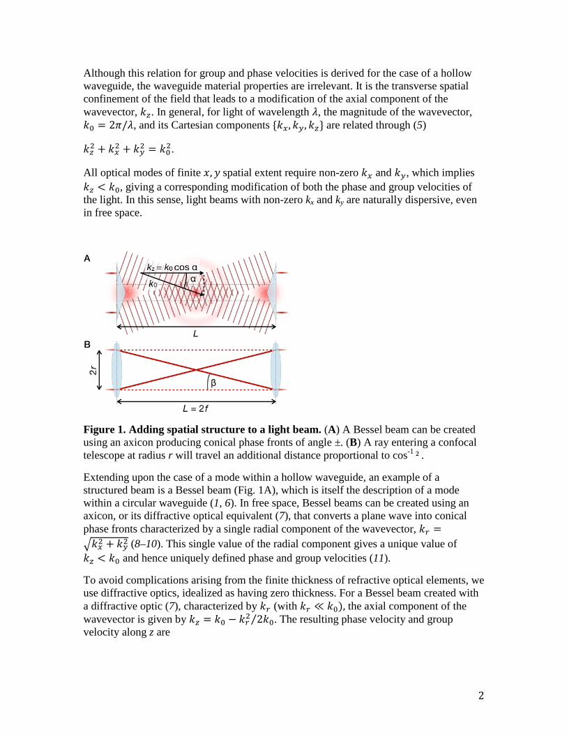
Figure 1. Adding spatial structure to a light beam. (A) A Bessel beam can be created using an axicon producing conical phase fronts of angle ±. (B) A ray entering a confocal telescope at radius r will travel an additional distance proportional to cos-1 ² .
Extending upon the case of a mode within a hollow waveguide, an example of a structured beam is a Bessel beam (Fig. 1A), which is itself the description of a mode within a circular waveguide (1, 6). In free space, Bessel beams can be created using an axicon, or its diffractive optical equivalent (7), that converts a plane wave into conical phase fronts characterized by a single radial component of the wavevector, 𝑘𝑟 =�𝑘𝑥2 + 𝑘𝑦2 (8–10). This single value of the radial component gives a unique value of 𝑘𝑧 < 𝑘0 and hence uniquely defined phase and group velocities (11).
To avoid complications arising from the finite thickness of refractive optical elements, we use diffractive optics, idealized as having zero thickness. For a Bessel beam created with a diffractive optic (7), characterized by 𝑘𝑟 (with 𝑘𝑟 ≪ 𝑘0), the axial component of the wavevector is given by 𝑘𝑧 = 𝑘0 − 𝑘𝑟2 2𝑘0⁄ . The resulting phase velocity and group velocity along z are

3
𝑣𝜙 = 𝑐 �1 − 𝑘𝑟2
2𝑘02�−1
and
𝑣𝑔,𝑧 = 𝑐 �1 − 𝑘𝑟2
2𝑘02�.
This modification of the phase and group velocities of Bessel beams has been examined in the classical, many-photon regime. Subtle changes in velocity have been previously studied using Bessel beams in the microwave (12) and optical regimes (13–15).
We demonstrate the intrinsic and linear nature of this reduction in group velocity, by measuring the delay in the arrival time of single photons. Over a propagation distance of 𝐿, the reduction in the group velocity compared to the plane-wave case gives a delay of
𝛿𝑧Bessel ≈ 𝐿 𝑘𝑟2
2𝑘02= 𝐿
2𝛼2. (1)
As an example, for an axicon designed to produce 𝛼 = 𝑘𝑟 𝑘0⁄ = 4.5 × 10⁻³ over a propagation distance of 1 m, we predict a delay of ~30 fs, corresponding to a spatial delay of 10 µm.
To measure the arrival time of single photons with femtosecond precision we adopt a method relying upon a quantum effect, namely, the Hong-Ou-Mandel (HOM) interference (16). A parametric down-conversion source is used to produce photon pairs that are strongly correlated in their wavelengths and their generation time. One photon can then act as a reference, against which the arrival of the other photon can be compared (Fig. 2). This second photon goes through a free-space propagation section, in which a first spatial light modulator (SLM) can be programmed to act as a diffractive optical element implementing axicons or lenses. A second SLM then reverses the structuring introduced by the first. When the arrival times of the two photons incident on a beam splitter are matched to a precision better than their coherence time, both photons emerge from the same output port. Under this matched condition, the coincidence rate for detection at the two output ports of the beam splitter falls to zero, which results in what is known as a HOM dip. The position of the dip is recorded as a function of the spatial shaping of the photon propagating in free space.

4
Figure 2. Experimental apparatus. Photon pairs from a parametric down-conversion source are separated by a knife-edge prism (KEP); a band-pass filter (BPF) sets the spectral profile of the down-converted light. Half-wave plates (HWP) are used to maximize the efficiency of the spatial light modulators (SLM), and match the polarization of the polarization-maintaining fibers (PMF). Signal and idler photons enter a fibre-coupled beam splitter (BS) (17), whose outputs are single-mode fibers (SMF) connected to avalanche photodiodes (SPAD). The SPADs feed a coincidence counter.
Figure 3. Experimental results for a Bessel beam. (A) Measured Hong-Ou-Mandel dips for two values of ± (±1 = 0.00225, red; ±2 = 0.00450, blue) and the ± = 0 case (black), with corresponding best fits (16). (B) Measured delays (hollow circles) and theoretical prediction from Eq. 1 (solid line), for different values of ±. The delays are expressed with respect to the ±= 0 case, corresponding to an unstructured collimated beam.
Taking the Bessel beam as our first example, the transverse structuring can be turned on and off for each value of path delay. The corresponding position of the HOM dip can then be directly compared between the two cases. Figure 3A shows the baseline-normalized coincidences for two different values of 𝛼 = 𝑘𝑟/𝑘0 (where we define the baseline as the coincidence count at path delay far from the dip position). In all cases the width of the HOM dips is the same, set by the 10 nm spectral bandwidth of the down-converted photons. The key result is that the HOM dip associated with the Bessel beam is delayed with respect to the dip obtained for a collimated beam. We measure a delay of 2.7±0.8 µm for the case of 𝛼1 = 0.00225 rad and 7.7±0.8 µm for 𝛼2 = 0.00450 rad. These measured values agree with theoretical predictions of 2.0 µm and 8.1 µm for 𝛼1 and 𝛼2, respectively.

5
The analytical form of this predicted delay (Eq. 1) suggests a simple geometrical model, where the delay arises from the additional length of the diagonal ray, propagating at an angle 𝛼 with respect to the optical axis. In Fig. 3B we compare the measured and predicted values for the delay, showing that Eq. 1 is valid over the range of angles that we tested for the Bessel beam.
Perhaps the most common form of spatial structuring of a light beam is focusing, which also leads to a modification of the axial component of the wavevector. We consider the propagation of light through a telescope comprising two identical lenses separated by twice their focal length, 𝑓 (i.e. a confocal telescope). Assuming a ray-optical model, a co-axial ray incident upon the first lens at radius 𝑟 emerges from the second lens co-axially at the same radius but inverted about the optical axis (Fig. 1B). Comparing the on-axis separation of the lenses to this diagonal distance gives an additional distance traveled of 𝛿𝑧 = 𝐿 cos 𝛽 − 𝐿 ≈ 𝑟2 𝑓⁄ ⁄ , where 𝛽 is the angle between ray and optical axis.
For a beam of Gaussian intensity distribution with 1/e2 radius 𝑤, the expectation value of 𝑟2 is ⟨𝑟2⟩ = 𝑤2 2⁄ . Therefore, the expected delay 𝛿𝑧Gauss for a Gaussian beam on transmission through a confocal telescope is
𝛿𝑧Gauss = 𝑤2 2⁄ 𝑓 = (𝑤 𝑓⁄ )2 × 𝑓 2⁄ , (2)
where w is the waist of the input beam. The delay is a quadratic function of the quantity 𝑤 𝑓⁄ , which can be considered as a measure of the beam divergence, defined by the numerical aperture of the system. The delay increases with increasing numerical aperture. This geometrical model and a rigorous theoretical calculation provide the same results for both the Bessel and confocal cases, within the same approximations (18, 19). The full theoretical model, however, applies to any arbitrary field. As the delay increases with the square of the numerical aperture, the delay becomes progressively harder to detect at longer distances.
The delay arising from focusing is shown in Fig. 4. Trace A shows the position of the HOM dip for the case of a collimated beam, and trace B shows its position for the case of 𝑓 = 0.40 m. We measure a delay of 7.7±0.4 µm for the focused case. This is comparable to the predicted delay based on Eq. 2 which, for our beam of 𝑤 = 2.32 ± 0.09 mm, is 6.7± 0.6 µm. The slight difference between our measurement and the predicted value is likely due to residual aberrations and imperfect collimation, leading to an ill-defined beam waist, upon which the delay is quadratically dependent.
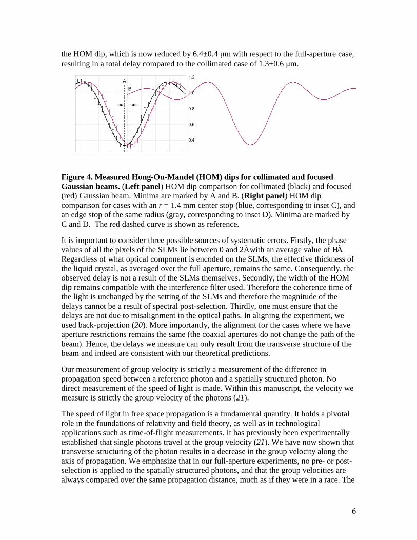
We further investigate the dependence of the delay upon the beam structure by introducing aperture restrictions to the beam, in the form of center and edge stops (insets of Fig. 4). Results are shown in traces C and D in Fig. 4, together with the full-aperture focused beam case (red line, trace B). A center stop increases the expectation value of 𝑟2, thereby increasing the delay compared to the full-aperture case. Trace C shows the dip with a center stop of radius 1.4 mm, as shown in inset C. We measure a dip position additionally delayed by 7.3±0.4 µm compared to the full-aperture focused beam, giving a total delay of 15.0±0.6 µm. Next, we introduce an edge stop of the same radius, as shown in inset D. By restricting the aperture, the expectation value of 𝑟2 is decreased, decreasing the delay with respect to the collimated case. Trace D shows the position of
6
the HOM dip, which is now reduced by 6.4±0.4 µm with respect to the full-aperture case, resulting in a total delay compared to the collimated case of 1.3±0.6 µm.
Figure 4. Measured Hong-Ou-Mandel (HOM) dips for collimated and focused Gaussian beams. (Left panel) HOM dip comparison for collimated (black) and focused (red) Gaussian beam. Minima are marked by A and B. (Right panel) HOM dip comparison for cases with an r = 1.4 mm center stop (blue, corresponding to inset C), and an edge stop of the same radius (gray, corresponding to inset D). Minima are marked by C and D. The red dashed curve is shown as reference.
It is important to consider three possible sources of systematic errors. Firstly, the phase values of all the pixels of the SLMs lie between 0 and 2À with an average value of HÀ. Regardless of what optical component is encoded on the SLMs, the effective thickness of the liquid crystal, as averaged over the full aperture, remains the same. Consequently, the observed delay is not a result of the SLMs themselves. Secondly, the width of the HOM dip remains compatible with the interference filter used. Therefore the coherence time of the light is unchanged by the setting of the SLMs and therefore the magnitude of the delays cannot be a result of spectral post-selection. Thirdly, one must ensure that the delays are not due to misalignment in the optical paths. In aligning the experiment, we used back-projection (20). More importantly, the alignment for the cases where we have aperture restrictions remains the same (the coaxial apertures do not change the path of the beam). Hence, the delays we measure can only result from the transverse structure of the beam and indeed are consistent with our theoretical predictions.
Our measurement of group velocity is strictly a measurement of the difference in propagation speed between a reference photon and a spatially structured photon. No direct measurement of the speed of light is made. Within this manuscript, the velocity we measure is strictly the group velocity of the photons (21).
The speed of light in free space propagation is a fundamental quantity. It holds a pivotal role in the foundations of relativity and field theory, as well as in technological applications such as time-of-flight measurements. It has previously been experimentally established that single photons travel at the group velocity (21). We have now shown that transverse structuring of the photon results in a decrease in the group velocity along the axis of propagation. We emphasize that in our full-aperture experiments, no pre- or post-selection is applied to the spatially structured photons, and that the group velocities are always compared over the same propagation distance, much as if they were in a race. The

7
effect can be derived from a simple geometric argument, which is also supported by a rigorous calculation of the harmonic average of the group velocity. Beyond light, the effect observed will have applications to any wave theory, including sound waves.
References
1. A. Yariv, “Quantum Electronics” (Wiley, 1988) [third edition]. 2. S. Feng, H.G. Winful, Opt. Lett. 26, 485–487 (2001). 3. R.W. Boyd, D.J. Gauthier, Science 326, 1074 (2009). 4. J.E. Vornehm, Jr., R.W. Boyd, in "Tutorials in Complex Photonic Media" (SPIE,
2009), chap. 19. 5. I.S. Grant, W.R. Phillips, Electromagnetism (Wiley, 1980) [second edition]. 6. E.R. Nagelberg, J. Shefer, Bell. Syst. Tech. J. 44, 1321 (1965). 7. S. Klewitz, S. Sogomonian, M. Woerner, S. Herminghaus, Opt. Commun. 154,
186 (1998). 8. R.M. Herman, T.A. Wiggins, J. Opt. Soc. Am. A 8, 932–942 (1991). 9. J.H. McLeod, J. Opt. Soc. Am. 44, 592 (1954). 10. A. Vasara, J. Turunen, A.T. Friberg, J. Opt. Soc. Am. A 6, 1748 (1989). 11. J.T. Lunardi, Phys. Lett. A 291, 66–72 (2001). 12. D. Mugnai, A. Ranfagni, R. Ruggeri, Phys. Rev. Lett. 84, 4830–4833 (2000). 13. K.B. Kuntz, B. Braverman, S.H. Youn, M. Lobino, A.E. Pessina et al., Phys. Rev.
A 79, 043802 (2009). 14. I. Alexeev, K.Y. Yim, H.M. Milchberg, Phys. Rev. Lett. 88, 073901 (2002). 15. P.W. Milonni, J. Phys. B 35, R31–R56 (2002). 16. C.K. Hong, Z.Y. Ou, L. Mandel, Phys. Rev. Lett. 59, 2044 (1987). 17. R. Kaltenbaek, B. Blauensteiner, M. {ukowski, M. Aspelmeyer, A. Zeilinger,
Phys. Rev. Lett. 96, 240502 (2006). 18. Z.L. Horvath, J. Vinko, Zs. Bor, D. von der Linde, Appl. Phys. B 63, 481–484
(1996). 19. Materials and methods are available as supporting material online. 20. M. McLaren, J. Romero, M.J. Padgett, F. Roux, A. Forbes, Phys. Rev. A 88,
033818 (2013). 21. A.M. Steinberg, P.G. Kwiat, R.Y. Chiao, Phys. Rev. Lett. 68, 2421–2424 (1992).
Acknowledgements
We thank Sonja Franke-Arnold for useful discussions. This work was supported by EPSRC through the COAM program, and by ERC through the TWISTS grant; D.F. acknowledges support from ERC through the MOLIGHT project. We thank Hamamatsu for their support. M.J.P. thanks the Royal Society.
M.J.P., D.F. and S.M.B. conceived the experiment and supervised the work; M.J.P., D.G. and J.R. designed the experiment; D.G. and J.R. constructed the experiment, acquired the data and carried out the data analysis; V.P., J.R., G.F., F.S. and S.M.B. further developed the theoretical model; J.R., D.G. and M.J.P. wrote the text with input from all co-authors.
8
Supplementary materials
The supplementary material includes details of the experimental materials and methods, and a theoretical treatment.

Supplementary Material for:
Photons that travel in free space slower than the speed of light
Daniel Giovannini1†, Jacquiline Romero1†, Vaclav Potocek1, Gergeley Ferenczi1, Fiona Speirits1, Stephen
M. Barnett1, Daniele Faccio2, Miles J. Padgett1∗
1 School of Physics and Astronomy, SUPA, University of Glasgow, Glasgow, UK2 School of Engineering and Physical Sciences, SUPA, Heriot-Watt University, Edinburgh, UK† These authors contributed equally to this work.
∗ Correspondence to: [email protected].
General case for free propagation
The delay that we observe in the experiment was estimated using a geometric, simple ray-optic model.
Here, we derive a rigorous theory that applies to any arbitrary field. It is experimentally established that
single photons travel at the group velocity, hence we will concern ourselves only with the group velocity.
The calculation of the photon travel time is based on the calculation of the group velocity of the photon,
which in general depends on the radial profile and position along the propagation axis. This is explicitly
shown for a Gaussian beam in (18), but we formulate it here for any arbitrary field. To take an effective
group velocity of the electromagnetic field over a volume in which the velocity is changing, one would need
to take a harmonic mean of the group velocity and also weight by the local intensity of the field. The group
velocity along the propagation of direction z of a beam with phase profile Φ and central frequency ω0 is
given by
v(z)g =
(∂2Φ∂z∂ω
)−1
ω0
.
The average velocity over an interval (z1, z2) becomes(1
z2 − z1
∫ z2
z1
(∂2Φ∂z∂ω
)ω0
dz
)−1
= (z2 − z1)
([(∂Φ∂ω
)ω0
]z2z1
)−1
which, when the integration is generalized to cover the whole volume between the z1 and z2 planes, using
the local intensity as a weighting function, simplifies to
(z2 − z1)/=
[∂
∂ω
(〈ψ(z, ω0)|ψ(z, ω)〉〈ψ(z, ω0)|ψ(z, ω0)〉
)ω0
]z2z1
.
Here the function ψ(x, y, z|ω), represented in the bra-ket notation as |ψ(z, ω)〉, denotes the transverse
profile of the spectral component of the beam at frequency ω in a scalar approximation. As is the convention,

2
we assume that the phase Φ is the complex argument of the functional value of ψ. This only gives positive
phase speed (in other words, it describes a wave travelling in the direction of the +z axis) if the notation is
chosen so that the kz term has a +i coefficient in the exponent.
If we use this group velocity to calculate the time it takes a wave packet to cover the distance z2 − z1,
we obtain
t = =
[∂
∂ω
(〈ψ(z, ω0)|ψ(z, ω)〉〈ψ(z, ω0)|ψ(z, ω0)〉
)ω0
]z2z1
=[∂
∂ω(arg〈ψ(z, ω0)|ψ(z, ω)〉)ω0
]z2z1
.
Thus, the delay of a nonplanar wavefront, compared to a plane wave that travels at speed c (which we
approximate with a collimated beam in the experiment) is
δz = ct− (z2 − z1) =[∂
∂k(arg〈ψ(z, k0)|ψ(z, k)〉)k0 − z
]z2z1
.
Our experiment is well within the paraxial approximation, in which case the above expression for δz can
be simplified even further. The wave function ψ(x, y, z|k) evolves from z1 to z2 according to the paraxial
wave equation,
∂ψ
∂z=
i
2k∆⊥ψ + ikψ,
where ∆⊥ = (∂/∂x)2 + (∂/∂y)2. Then,
|ψ(z2, k)〉 = exp(iL
2k∆⊥ + ikL
)|ψ(z1, k)〉,
where L = z2 − z1,
〈ψ(z2, k0)|ψ(z2, k)〉 = 〈ψ(z1, k0)| exp(iL
2k∆⊥ −
iL
2k0∆⊥ + i(k − k0)L
)|ψ(z1, k)〉,
and
δz = − L
2k20
<〈ψ(z1, k0)|∆⊥|ψ(z1, k0)〉〈ψ(z1, k0)|ψ(z1, k0)〉
.
Note that ∆⊥ can be written as −k2⊥, where
k⊥ = −i∇⊥
is the quantum mechanical operator corresponding to the transverse wave vector. This implies that ∆⊥ has
a negative real expectation value and the final expression for δz can be established as
δz =L
2k20
〈k2⊥〉|ψ(z1,k0)〉. (1)
Interestingly, as a side result we can see that the effective group velocity
vg =c
1 + 〈k2⊥〉
2k20
≈ c
(1−〈k2⊥〉
2k20
)
is invariant under the free propagation and always smaller than c.
3
Special cases: Bessel and Gaussian beams
We can now use Eq. 1 to calculate the delays for the cases of Bessel and Gaussian beams. The former
is simple in that there is a single value of |k⊥|, which is exactly the radial component of the wavevector,
denoted kr in the main text. Using this we find that in our case (Fig. 1A) the delay is
δzBessel = Lk2r
2k20
.
For a Gaussian beam of initial beam waist w0, focused by a lens of focal length f , the quantity 〈k2⊥〉 can
be calculated as
〈k2⊥〉 =
2w2f
,
where wf = 2f/(k0w0) is the waist of the focused beam. This leads to an expression for the delay in our
case (Fig. 1B)
δzGauss =w2
0
2f.
We underline that these equations are exactly the same as that obtained from a simple geometric model as
described in the main text.
For the cases where we put sharp aperture restrictions (the center and edge stops), a direct application
of Eq. 1 leads to an infinite slowing down because of the diffraction on the boundaries, which result in a
broad-tailed distribution of k⊥. However, we can still give an estimate of the delays by recognizing that
δzGauss =w2
0
2f=(w2
0
2
)1f
=〈r2〉f,
where 〈r2〉 is the expectation value of the square of the radius of the beam weighted by the Gaussian inten-
sity distribution. For the cases where we place center and edge stops of radius 1.4 mm, we can renormalize
the resulting obstructed and truncated Gaussian distributions and calculate 〈r2〉. Doing so leads to delay
estimates of 11.6 µm and 2.1 µm for the center and edge stops, respectively, compared to the collimated
case.
A more careful analysis of the detection part shows that the broad tail of the distribution of k⊥ is removed
by means of postselection on the principal maximum, naturally implemented in our case by the geometry
of the second SLM. Taking into account the shape of the aperture at the end of the free-space propagation,
it can be shown that the full prediction of δz can actually be expressed as the weak value
δz =L
2k20
<〈ψ′(z1, k0)|k2
⊥|ψ(z1, k0)〉〈ψ′(z1, k0)|ψ(z1, k0)〉
,
4
with |ψ′(z1, k0)〉 being the effective projection state at z2 back-evolved to the plane z1. This reduces to Eq. 1
in the case where |ψ′(z1, k0)〉 = |ψ(z1, k0)〉, corresponding to detection of the entire wavefront. Without
going into further detail, we conclude that this description presents a good quantitative agreement with our
experimental results and could possibly lead to other interesting cases.


![T.C.8 3.1.2 JENERATÖR HESABI Kanat uç hız oranı; 𝜆=7 seçilmiştir. 𝜆= 𝜔.𝑅 7= 𝜔.0,223 5 𝜔=156,95 [ 𝑎 ] 𝜔= . 30 =1498,76 [ 𝑣 𝑎𝑘] Winglet tablosundan;](https://static.fdocuments.net/doc/165x107/60b4727a0bda2724e1361ff3/tc-8-312-jeneratr-hesabi-kanat-u-hz-oran-oe7-seilmitir-oe.jpg)