
GIGGLEPIN MBS MOTOR BRAKE SYSTEM INSTRUCTIONS
19
1 GIGGLEPIN MBS MOTOR BRAKE SYSTEM INSTRUCTIONS
Transcript of GIGGLEPIN MBS MOTOR BRAKE SYSTEM INSTRUCTIONS

1
GIGGLEPIN MBS
MOTOR BRAKE SYSTEM
INSTRUCTIONS

2
What’s in the box. For a Twin MBS kit, you will have
2 x Brake units 6 x O-Ring Seals 4 x Motor Bolts - Bow 2 kit only 12 x M6 Washers 2 x MBS Gaskets 4 x M6 Nylocs 1 x Wiring Harness 4 x Mounting Studs 6m of 6mm Air Pipe 4 X Spacers 1 x On-Off Switch 1 x 6mm “T” Piece 1 x Switch Guard 1 x Airfit “Y” 6 x MBS Mounting Bolts 1 x ¼ BSP-6mm Air Fitting 2 x 3mm Drill Bits 6 x Drive Pegs 1 x Drill Jig 1 x M4 Cap Head Set Screw 2 x Motor Adapters – See Below for Bow motor and XP motor adapter types Items you will need to fit the MBS
A drill 10mm and 11mm sockets or spanners Cutters RTV silicon sealant – Black if possible Stud lock Copper slip – anti seize compound Basic tools to fit into existing wiring
The Bow Motor Adapter is on the Left of the image above, the XP Motor Adapter is on the Right – Please ensure that you have ordered the correct adapter for your motor fitment. These instructions are based on new motors being fitted with the Motor Brake System, if you are using your existing motors we would advise removing them from your winch a giving them a good clean up and check over before fitting the MBS.

3
Step 1
Remove the end cap from the motor, keep the 2 x Motor bolts, if fitting to an existing motor there are replacement Bow 2 motor bolts in the Bow 2 kits. Bow motor shown – the XP motor is the same principle, you will need to retain the XP bolts as there are none supplied with the kit.

4
Using a suitable puller, remove the bearing on the end of the motor shaft, Remove the armature from the motor casing.
Screw the M4 Cap Head Set Screw into the Drill Jig

5
Install the Drill Jig on to the end of the motor shaft with the recessed end next to the Copper Armature, tighten the retaining M4 Fixing and drill 3 x 3 mm holes through the Jig to a depth of 11mm in the shaft. Care must be taken when drilling, not to shatter the drill when passing through the hole in the end of the motor shaft
Once drill, remove the Jig and insert the 3 drive pins into the drilled holes.

6
Make sure the pins are fitted as per the above image Reassemble the armature into the motor casing and proceed to step 2
7
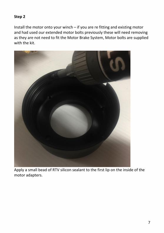
Step 2 Install the motor onto your winch – if you are re fitting and existing motor and had used our extended motor bolts previously these will need removing as they are not need to fit the Motor Brake System, Motor bolts are supplied with the kit.
Apply a small bead of RTV silicon sealant to the first lip on the inside of the motor adapters.

8
And install onto the rear of the motors with the standard motor bolts, apply a little copper slip to the threads, making sure to orientate the motor adapter as in the image above.
Repeat the steps on the second motor.

9
The process is the same for installing the Motor Brake system to an XP motor, the only difference being the XP Motor Adapters are different in form as can be seen above.
Install 1 x M6 flat washer and 1 x O-ring onto each of the M6 bolts Apply a little copper slip to the threads.

10
Using the M6 bolts to locate the gasket, line the key way in the brake assembly with the keys fitted to the motor shaft, and with the dowel uppermost, slide the brake assembly on the end of the motor shaft.
Tighten the 3 x M6 bolts, repeat with second brake assembly

11
Step 3 With both brake assemblies installed on each motor.
Insert the “T” piece as shown above, using air pipe cut off the 6m roll
Apply stud lock to the 4 x M6 studs

12
And install into the threaded holes on the rear of the brake assemblies.
Next install the spacers onto the M6 studs
13
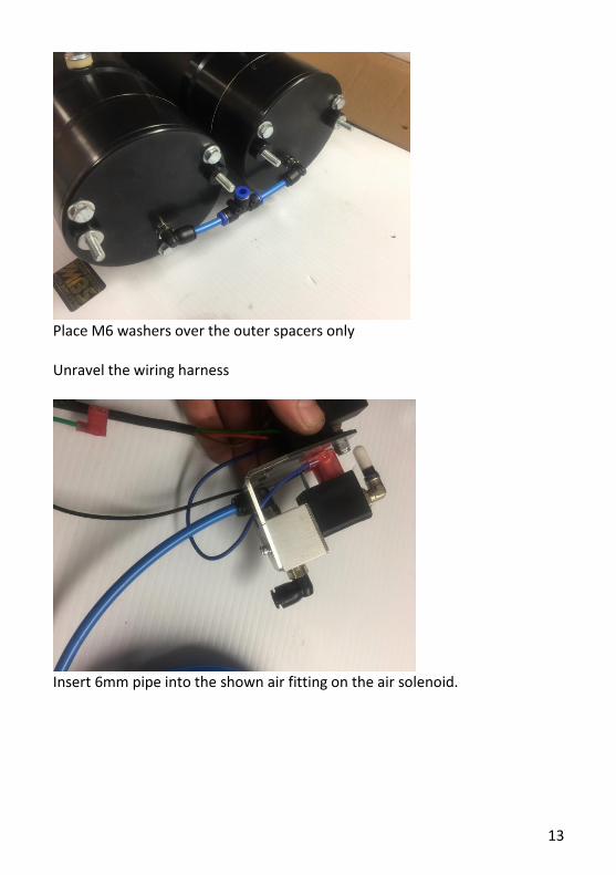
Place M6 washers over the outer spacers only Unravel the wiring harness
Insert 6mm pipe into the shown air fitting on the air solenoid.

14
Fit the solenoid mounting bracket over the 2 centre studs and cut the air pipe to fit as shown, and attach to the “T” piece.
Attach your Albrights to the studs using the 4 x M6 washers and M6 Nylocs

15
Fit the wiring to the solenoids as shown, and the earth connection to the rear motor earth point, keep the cabling neat with cable ties.
Install an air supply to the MBS – using the supplied 6mm Air Pipe, attached to the solenoid as shown above, included in the kit is a “Y” piece and ¼ BSP x 6mm adapter to fit directly onto an ARB type compressor.

16
MBS Wiring Diagram
Contained in the MBS kit is a fully built up wiring harness Should you need to modify it to fit your application please find below the essential wiring connections.
The ring terminal on the black wire is to be connected to the negative motor
connection – found on the underside of the motor (M8 Bolt usually)
The Brown wire in the harness requires a constant fused live feed via the
supplied switch (and switch guard), when supplied with a live feed the brakes
are autonomous in operation, as you release the winch in/out switch the
Motor Brakes will immediately operate, bring your winch to a near instant
halt, with this live feed disabled the Motor Brakes will NOT engage when the
winch control switch is released, your winch will revert to using its built-in
brake mechanism.
If your air supply fails – or is damaged in competition, the Motor Brakes will
no longer operate, but you will still be able to operate your winch – again
reverting to its built-in brake mechanism.
If you have any questions please do not hesitate to get in touch with us.

17

18
A separate Gigglepin Power Bar kit is available for both Bow 2 and Bow 2+ motors, in both single motor and twin motor versions, please contact your local Gigglepin Dealer if you require a set for your winch.
GIGGLEPIN MBS
MOTOR BRAKE SYSTEM
INSTRUCTIONS

19


![AC/DC Geared Motor and Gearhead - raveo.czkatalog]_DKM_A... · DKM Products Overview Induction Motor 2 Pole Motor Reversible Motor E.M. Brake Motor Clutch & Brake Motor Torque Motor](https://static.fdocuments.net/doc/165x107/5ca5afa988c9930a6e8c9362/acdc-geared-motor-and-gearhead-raveocz-katalogdkma-dkm-products-overview.jpg)

