GFK-0732 PDF GE Fanuc Manuals Series 9030 - PDF Supply
173
GE Fanuc Manual Series 90-30 1-800-360-6802 [email protected] GFK-0732 Buy GE Fanuc Series 90-30 NOW! ECLiPS English Control Language Programming Sys- tem Copyright 2013 PDFsupply.com All Rights Resevered
Transcript of GFK-0732 PDF GE Fanuc Manuals Series 9030 - PDF Supply

GE Fanuc Manual Series 90-30
GFK-0732
Buy GE Fanuc Series 90-30 NOW!
ECLiPS English Control Language Programming Sys-tem
Copyright 2013 PDFsupply.com All Rights Resevered

Î
GE Fanuc Automation
State Logic� Products
ECLiPS EnglishControl LanguageProgramming SystemFor Series 90�-30 PLC
User’s Guide
GFK-0732B March 1998
GFL–002
Warnings, Cautions, and Notesas Used in this Publication
Warning
Warning notices are used in this publication to emphasize that hazardous voltages,currents, temperatures, or other conditions that could cause personal injury exist in thisequipment or may be associated with its use.
In situations where inattention could cause either personal injury or damage toequipment, a Warning notice is used.
Caution
Caution notices are used where equipment might be damaged if care is not taken.
Note
Notes merely call attention to information that is especially significant to understandingand operating the equipment.
This document is based on information available at the time of its publication. Whileefforts have been made to be accurate, the information contained herein does notpurport to cover all details or variations in hardware or software, nor to provide forevery possible contingency in connection with installation, operation, or maintenance.Features may be described herein which are not present in all hardware and softwaresystems. GE Fanuc Automation assumes no obligation of notice to holders of thisdocument with respect to changes subsequently made.
GE Fanuc Automation makes no representation or warranty, expressed, implied, orstatutory with respect to, and assumes no responsibility for the accuracy, completeness,sufficiency, or usefulness of the information contained herein. No warranties ofmerchantability or fitness for purpose shall apply.
The following are trademarks of GE Fanuc Automation North America, Inc.
Alarm Master CIMSTAR Helpmate PROMACRO Series SixCIMPLICITY GEnet Logicmaster Series One Series 90CIMPLICITY 90–ADS Genius Modelmaster Series Three VuMasterCIMPLICITY PowerTRAC Genius PowerTRAC ProLoop Series Five Workmaster
Copyright 1992-1998 GE Fanuc Automation North America, Inc.All Rights Reserved
iii GFK-0732B
Preface
Content of this ManualChapter 1. Getting Started – This chapter has general foundational information aboutthe ECLiPS software product. There is a general overview of the product, instructionson using this manual, installation procedures, hardware requirements, and sources ofinformation about using ECLiPS.
Chapter 2. State Logic� Control Theory – This chapter has two main topics. The firstpart discusses State Logic Control Theory and how it differs from traditional controlmodels. The second part discusses the ECLiPS implementation of State Logic Control.
Chapter 3. Creating A Control Program – This chapter presents the fundamental con-cepts of how a control program can be built using ECLiPS. Every designer will develophis own style in using ECLiPS. ECLiPS is designed to support and even to encouragepersonal or corporate program development styles.
Chapter 4. Programming Tutorial – This chapter presents a step by step procedure forwriting a control program for a specific application. Follow along duplicating each key-board entry on your own computer. Watch for the text displayed in bold italics, theseare the lines that you should enter.
Chapter 5. Helpful Hints – The hints and suggestions found in this chapter have beendeveloped by ECLiPS and State Language programmers in an effort to make the user’sfirst programming experience as productive as possible. There are two parts to thischapter, one giving hints for programming and the other has suggestions for using thetools provided as part of ECLiPS.
Chapter 6. Online Tutorial – This chapter is a tutorial that explains the steps necessaryto get a control program running in the State Logic Processor. This chapter covers con-figuring the Series 90–70 CPU with Logicmaster 90 and how to load, execute, monitor,and interact with an ECLiPS control program.
Chapter 7. Creating Program Documentation – This chapter describes how to use theECLiPS program documentation features. The topics covered are printing program doc-umentation, including the English program, I/O map, Data Listing, Task and State listing,and Cross Reference Listing. Printing information for using the CCM protocol and docu-menting the ECLiPS program are also covered.
Chapter 8. Reference – This chapter is designed to provide information about the de-tails of the ECLiPS control language and how to use the ECLiPS software package. Thechapter starts with a description of the State Logic Language and Keywords then dis-cusses the setup of the Series 90–70 control system, then each of the menu options isexplained, and finally the ECLiPS specifications are displayed.
� State Logic is a registered trademark of Adatek, Inc.

Preface
iv ECLiPS English Control Language Programming System User’s Guide – March 1998 GFK-0732B
We Welcome Your Comments and Suggestions
At GE Fanuc automation, we strive to produce quality technical documentation. Afteryou have used this manual, please take a few moments to complete and return theReader ’s Comment Card located on the next page.
Contents
vii
GFK–0732B ECLiPS English Control Language Programming Systems User’s Guide – March 1998
Chapter 1 Getting Started 1-1 . . . . . . . . . . . . . . . . . . . . . . . . . . . . . . . . . . . . . . . . . . . .
Overview 1-1 . . . . . . . . . . . . . . . . . . . . . . . . . . . . . . . . . . . . . . . . . . . . . . . . . . . . . . .
How to Use this Manual 1-1 . . . . . . . . . . . . . . . . . . . . . . . . . . . . . . . . . . . . . . . . . . .
Notational Conventions: 1-2 . . . . . . . . . . . . . . . . . . . . . . . . . . . . . . . . . . . . . . . .
Brief Description of the Manual Chapters 1-2 . . . . . . . . . . . . . . . . . . . . . . . . .
Hardware Requirements 1-3 . . . . . . . . . . . . . . . . . . . . . . . . . . . . . . . . . . . . . . . .
Installation 1-3 . . . . . . . . . . . . . . . . . . . . . . . . . . . . . . . . . . . . . . . . . . . . . . . . . . . .
Register Your Product 1-3 . . . . . . . . . . . . . . . . . . . . . . . . . . . . . . . . . . . . . . . . . .
Getting Help 1-4 . . . . . . . . . . . . . . . . . . . . . . . . . . . . . . . . . . . . . . . . . . . . . . . . . .
Chapter 2 State Logic Control Theory 2-1 . . . . . . . . . . . . . . . . . . . . . . . . . . . . . . . . . .
State Logic Control Theory 2-1 . . . . . . . . . . . . . . . . . . . . . . . . . . . . . . . . . . . . . . . . .
The Concept of Finite States 2-2 . . . . . . . . . . . . . . . . . . . . . . . . . . . . . . . . . . . . .
What Makes State Control Logic Different 2-3 . . . . . . . . . . . . . . . . . . . . . . . . .
Developing State Logic Programs with ECLiPS 2-4 . . . . . . . . . . . . . . . . . . . . .
Scan Overview 2-9 . . . . . . . . . . . . . . . . . . . . . . . . . . . . . . . . . . . . . . . . . . . . . . . .
Interaction Between Tasks 2-9 . . . . . . . . . . . . . . . . . . . . . . . . . . . . . . . . . . . . . .
Chapter 3 Creating A Control Program 3-1 . . . . . . . . . . . . . . . . . . . . . . . . . . . . . . . . .
Outline the Application 3-2 . . . . . . . . . . . . . . . . . . . . . . . . . . . . . . . . . . . . . . . . . . . .
Identify the Tasks 3-2 . . . . . . . . . . . . . . . . . . . . . . . . . . . . . . . . . . . . . . . . . . . . . .
Identify The States 3-2 . . . . . . . . . . . . . . . . . . . . . . . . . . . . . . . . . . . . . . . . . . . . .
Identify the Statements 3-3 . . . . . . . . . . . . . . . . . . . . . . . . . . . . . . . . . . . . . . . . .
Writing The Program 3-3 . . . . . . . . . . . . . . . . . . . . . . . . . . . . . . . . . . . . . . . . . . . . . .
Using English Names in the ECLiPS Program 3-4 . . . . . . . . . . . . . . . . . . . . . .
Statement Structures 3-5 . . . . . . . . . . . . . . . . . . . . . . . . . . . . . . . . . . . . . . . . . . .
Constructing Statements 3-6 . . . . . . . . . . . . . . . . . . . . . . . . . . . . . . . . . . . . . . . .
Using Keywords, Synonyms and Filler Words 3-6 . . . . . . . . . . . . . . . . . . . . . .
Using Variables 3-7 . . . . . . . . . . . . . . . . . . . . . . . . . . . . . . . . . . . . . . . . . . . . . . . .
Program Scan 3-8 . . . . . . . . . . . . . . . . . . . . . . . . . . . . . . . . . . . . . . . . . . . . . . . . .
Contents
viii
GFK–0732B ECLiPS English Control Language Programming Systems User’s Guide – March 1998
Chapter 4 Programming Tutorial 4-1 . . . . . . . . . . . . . . . . . . . . . . . . . . . . . . . . . . . . . .
Tutorial Procedure 4-1 . . . . . . . . . . . . . . . . . . . . . . . . . . . . . . . . . . . . . . . . . . . . . . . .
The Control Application 4-2 . . . . . . . . . . . . . . . . . . . . . . . . . . . . . . . . . . . . . . . . . . .
Outline the Application 4-3 . . . . . . . . . . . . . . . . . . . . . . . . . . . . . . . . . . . . . . . . . . . .
Identify the Tasks 4-3 . . . . . . . . . . . . . . . . . . . . . . . . . . . . . . . . . . . . . . . . . . . . . .
Identify the States 4-3 . . . . . . . . . . . . . . . . . . . . . . . . . . . . . . . . . . . . . . . . . . . . .
Identify the Statements 4-6 . . . . . . . . . . . . . . . . . . . . . . . . . . . . . . . . . . . . . . . . .
Writing the Program 4-9 . . . . . . . . . . . . . . . . . . . . . . . . . . . . . . . . . . . . . . . . . . . . . .
Identify the I/O 4-9 . . . . . . . . . . . . . . . . . . . . . . . . . . . . . . . . . . . . . . . . . . . . . . . .
The Basics of ECLiPS 4-10 . . . . . . . . . . . . . . . . . . . . . . . . . . . . . . . . . . . . . . . . . . .
Program the Fill Station Task 4-12 . . . . . . . . . . . . . . . . . . . . . . . . . . . . . . . . . . . .
Define Undefined Words 4-15 . . . . . . . . . . . . . . . . . . . . . . . . . . . . . . . . . . . . . . .
Checking Your Work and Making Changes 4-18 . . . . . . . . . . . . . . . . . . . . . . . .
Program the Mix Station Task 4-19 . . . . . . . . . . . . . . . . . . . . . . . . . . . . . . . . . . . .
Conveyor 4-20 . . . . . . . . . . . . . . . . . . . . . . . . . . . . . . . . . . . . . . . . . . . . . . . . . . . . .
Advanced Programming Terms and Diagnostics 4-21 . . . . . . . . . . . . . . . . . . . .
Chapter 5 Helpful Hints 5-1 . . . . . . . . . . . . . . . . . . . . . . . . . . . . . . . . . . . . . . . . . . . . .
Programming Hints 5-1 . . . . . . . . . . . . . . . . . . . . . . . . . . . . . . . . . . . . . . . . . . . . . . .
Outputs are OFF by Default 5-1 . . . . . . . . . . . . . . . . . . . . . . . . . . . . . . . . . . . . .
Write Term Considerations 5-2 . . . . . . . . . . . . . . . . . . . . . . . . . . . . . . . . . . . . . .
Calculations and a Scanning Operating System 5-3 . . . . . . . . . . . . . . . . . . . .
Task Design 5-3 . . . . . . . . . . . . . . . . . . . . . . . . . . . . . . . . . . . . . . . . . . . . . . . . . . .
Read Term Considerations 5-4 . . . . . . . . . . . . . . . . . . . . . . . . . . . . . . . . . . . . . .
Timer Considerations 5-5 . . . . . . . . . . . . . . . . . . . . . . . . . . . . . . . . . . . . . . . . . . .
Documentation Hints 5-6 . . . . . . . . . . . . . . . . . . . . . . . . . . . . . . . . . . . . . . . . . .
Program Scan 5-7 . . . . . . . . . . . . . . . . . . . . . . . . . . . . . . . . . . . . . . . . . . . . . . . . .
Hints for Using ECLiPS Features 5-11 . . . . . . . . . . . . . . . . . . . . . . . . . . . . . . . . . . . .
How to Use the ECLiPS Menus 5-11 . . . . . . . . . . . . . . . . . . . . . . . . . . . . . . . . . .
Using ECLiPS Hot Keys 5-11 . . . . . . . . . . . . . . . . . . . . . . . . . . . . . . . . . . . . . . . . .
ECLiPS Word Processing Functions 5-11 . . . . . . . . . . . . . . . . . . . . . . . . . . . . . . .
How to Use ECLiPS Lists 5-12 . . . . . . . . . . . . . . . . . . . . . . . . . . . . . . . . . . . . . . .

Contents
ix
GFK–0732B ECLiPS English Control Language Programming Systems User’s Guide – March 1998
Chapter 6 Online Tutorial 6-1 . . . . . . . . . . . . . . . . . . . . . . . . . . . . . . . . . . . . . . . . . . . .
Setting Up the Series 90-30 State Logic Control System 6-2 . . . . . . . . . . . . . . . . .
Configuring the State Logic Processor 6-2 . . . . . . . . . . . . . . . . . . . . . . . . . . . .
Enter the Initialization Ladder Program 6-3 . . . . . . . . . . . . . . . . . . . . . . . . . . .
Enable Outputs and Start Program Running 6-3 . . . . . . . . . . . . . . . . . . . . . . .
DownLoad a Program 6-3 . . . . . . . . . . . . . . . . . . . . . . . . . . . . . . . . . . . . . . . . . . . . .
Debug Mode Screen 6-4 . . . . . . . . . . . . . . . . . . . . . . . . . . . . . . . . . . . . . . . . . . . .
Put SLP in Run Mode 6-5 . . . . . . . . . . . . . . . . . . . . . . . . . . . . . . . . . . . . . . . . . . . . .
Toggle Simulation Mode 6-5 . . . . . . . . . . . . . . . . . . . . . . . . . . . . . . . . . . . . . . . .
RUN or HALT Program 6-5 . . . . . . . . . . . . . . . . . . . . . . . . . . . . . . . . . . . . . . . . .
Controlling and Observing the Fill Station 6-5 . . . . . . . . . . . . . . . . . . . . . . . . . . . .
Monitor 6-5 . . . . . . . . . . . . . . . . . . . . . . . . . . . . . . . . . . . . . . . . . . . . . . . . . . . . . .
View 6-6 . . . . . . . . . . . . . . . . . . . . . . . . . . . . . . . . . . . . . . . . . . . . . . . . . . . . . . . . .
Controlling and Observing the Mix Station 6-6 . . . . . . . . . . . . . . . . . . . . . . . . . . .
Change 6-6 . . . . . . . . . . . . . . . . . . . . . . . . . . . . . . . . . . . . . . . . . . . . . . . . . . . . . . .
Display 6-6 . . . . . . . . . . . . . . . . . . . . . . . . . . . . . . . . . . . . . . . . . . . . . . . . . . . . . . .
Force 6-7 . . . . . . . . . . . . . . . . . . . . . . . . . . . . . . . . . . . . . . . . . . . . . . . . . . . . . . . . .
Trace 6-7 . . . . . . . . . . . . . . . . . . . . . . . . . . . . . . . . . . . . . . . . . . . . . . . . . . . . . . . . .
PLC I/O 6-7 . . . . . . . . . . . . . . . . . . . . . . . . . . . . . . . . . . . . . . . . . . . . . . . . . . . . . .
PID Loop Tuning Screen 6-7 . . . . . . . . . . . . . . . . . . . . . . . . . . . . . . . . . . . . . . . . . . .
Viewing and Clearing CPU Faults 6-7 . . . . . . . . . . . . . . . . . . . . . . . . . . . . . . . . . . .
Chapter 7 Creating Program Documentation 7-1 . . . . . . . . . . . . . . . . . . . . . . . . . . . .
Program Documentation Features 7-1 . . . . . . . . . . . . . . . . . . . . . . . . . . . . . . . . . . .
Header/Footer 7-1 . . . . . . . . . . . . . . . . . . . . . . . . . . . . . . . . . . . . . . . . . . . . . . . . .
Directing the Output 7-2 . . . . . . . . . . . . . . . . . . . . . . . . . . . . . . . . . . . . . . . . . . .
Documentation Options 7-2 . . . . . . . . . . . . . . . . . . . . . . . . . . . . . . . . . . . . . . . .
Commenting the ECLiPS Program 7-6 . . . . . . . . . . . . . . . . . . . . . . . . . . . . . . . . . .
Contents
x
GFK–0732B ECLiPS English Control Language Programming Systems User’s Guide – March 1998
Chapter 8 Reference 8-1 . . . . . . . . . . . . . . . . . . . . . . . . . . . . . . . . . . . . . . . . . . . . . . . . .
Language Description 8-1 . . . . . . . . . . . . . . . . . . . . . . . . . . . . . . . . . . . . . . . . . . . . .
Program Structure 8-1 . . . . . . . . . . . . . . . . . . . . . . . . . . . . . . . . . . . . . . . . . . . . .
Language Structure Notational Conventions 8-2 . . . . . . . . . . . . . . . . . . . . . .
Functional Expressions 8-3 . . . . . . . . . . . . . . . . . . . . . . . . . . . . . . . . . . . . . . . . .
Conditional Expressions 8-9 . . . . . . . . . . . . . . . . . . . . . . . . . . . . . . . . . . . . . . . .
Mathematical Calculations 8-13 . . . . . . . . . . . . . . . . . . . . . . . . . . . . . . . . . . . . . .
Variables 8-13 . . . . . . . . . . . . . . . . . . . . . . . . . . . . . . . . . . . . . . . . . . . . . . . . . . . . . .
Language Structure Summary 8-15 . . . . . . . . . . . . . . . . . . . . . . . . . . . . . . . . . . .
Grammatical Rules 8-18 . . . . . . . . . . . . . . . . . . . . . . . . . . . . . . . . . . . . . . . . . . . . .
Using the System Clock 8-18 . . . . . . . . . . . . . . . . . . . . . . . . . . . . . . . . . . . . . . . . .
Standard Predefined Keyword Set 8-19 . . . . . . . . . . . . . . . . . . . . . . . . . . . . . . .
Filler Words 8-24 . . . . . . . . . . . . . . . . . . . . . . . . . . . . . . . . . . . . . . . . . . . . . . . . . . .
PID Loops 8-24 . . . . . . . . . . . . . . . . . . . . . . . . . . . . . . . . . . . . . . . . . . . . . . . . . . . .
Perform Functions 8-32 . . . . . . . . . . . . . . . . . . . . . . . . . . . . . . . . . . . . . . . . . . . . .
Specialized Perform Functions 8-43 . . . . . . . . . . . . . . . . . . . . . . . . . . . . . . . . . . .
Keyboard Definitions 8-44 . . . . . . . . . . . . . . . . . . . . . . . . . . . . . . . . . . . . . . . . . . . . . .
Series 90-30 State Logic Control System 8-45 . . . . . . . . . . . . . . . . . . . . . . . . . . . . . .
SLP/CPU Interface 8-45 . . . . . . . . . . . . . . . . . . . . . . . . . . . . . . . . . . . . . . . . . . . . .
Serial Ports 8-49 . . . . . . . . . . . . . . . . . . . . . . . . . . . . . . . . . . . . . . . . . . . . . . . . . . . .
State Engine Scan Considerations 8-54 . . . . . . . . . . . . . . . . . . . . . . . . . . . . . . . .
Other State Engine Setup Options 8-59 . . . . . . . . . . . . . . . . . . . . . . . . . . . . . . .
Making a Permanent Copy of the Terminal Log 8-59 . . . . . . . . . . . . . . . . . . . .
Simulation Mode 8-59 . . . . . . . . . . . . . . . . . . . . . . . . . . . . . . . . . . . . . . . . . . . . . .
Setting the System Clock 8-60 . . . . . . . . . . . . . . . . . . . . . . . . . . . . . . . . . . . . . . . .
ECLiPS Menu System 8-60 . . . . . . . . . . . . . . . . . . . . . . . . . . . . . . . . . . . . . . . . . . . . .
Program Mode 8-60 . . . . . . . . . . . . . . . . . . . . . . . . . . . . . . . . . . . . . . . . . . . . . . . .
Debug Mode 8-71 . . . . . . . . . . . . . . . . . . . . . . . . . . . . . . . . . . . . . . . . . . . . . . . . . .
Online Modify 8-79 . . . . . . . . . . . . . . . . . . . . . . . . . . . . . . . . . . . . . . . . . . . . . . . .
Setup and ECLiPS Memory Usage 8-80 . . . . . . . . . . . . . . . . . . . . . . . . . . . . . . .
Quit 8-80 . . . . . . . . . . . . . . . . . . . . . . . . . . . . . . . . . . . . . . . . . . . . . . . . . . . . . . . . .
Specifications 8-81 . . . . . . . . . . . . . . . . . . . . . . . . . . . . . . . . . . . . . . . . . . . . . . . . . . . .
Content of this Manual iii . . . . . . . . . . . . . . . . . . . . . . . . . . . . . . . . . . . . . . . . . . . .
We Welcome Your Comments and Suggestions vi . . . . . . . . . . . . . . . . . . . . . . .

Contents
xi
GFK–0732B ECLiPS English Control Language Programming Systems User’s Guide – March 1998
Table 8-1. Discrete Memory Types 8-46 . . . . . . . . . . . . . . . . . . . . . . . . . . . . . . . . . . . . Table 8-2. Register Memory Types 8-46 . . . . . . . . . . . . . . . . . . . . . . . . . . . . . . . . . . . . Table 8-3. 90-30 SLP Discrete and Register 8-47 . . . . . . . . . . . . . . . . . . . . . . . . . . . . . Table 8-4. State Engine Data Types and CCM References 8-50 . . . . . . . . . . . . . . . . . Table 8-5. PID Parameter Table 8-53 . . . . . . . . . . . . . . . . . . . . . . . . . . . . . . . . . . . . . . .
Contents
xii
GFK–0732B ECLiPS English Control Language Programming Systems User’s Guide – March 1998
Figure 2-1. State Diagrams 2-2 . . . . . . . . . . . . . . . . . . . . . . . . . . . . . . . . . . . . . . . . . . Figure 3-1. Program Scan 3-9 . . . . . . . . . . . . . . . . . . . . . . . . . . . . . . . . . . . . . . . . . . . . Figure 3-2. Statement Scan 3-10 . . . . . . . . . . . . . . . . . . . . . . . . . . . . . . . . . . . . . . . . . . Figure 4-1. Tutorial Application Drawing 4-2 . . . . . . . . . . . . . . . . . . . . . . . . . . . . . . Figure 4-2. Main Menu 4-11 . . . . . . . . . . . . . . . . . . . . . . . . . . . . . . . . . . . . . . . . . . . . . . Figure 4-3. Project Menu 4-12 . . . . . . . . . . . . . . . . . . . . . . . . . . . . . . . . . . . . . . . . . . . . Figure 4-4. Conveyor Task 4-20 . . . . . . . . . . . . . . . . . . . . . . . . . . . . . . . . . . . . . . . . . . . Figure 5-1. Program Scan 5-8 . . . . . . . . . . . . . . . . . . . . . . . . . . . . . . . . . . . . . . . . . . . . Figure 5-2. Statement Scan 5-9 . . . . . . . . . . . . . . . . . . . . . . . . . . . . . . . . . . . . . . . . . . Figure 5-3. Program Scan with GO Terms 5-10 . . . . . . . . . . . . . . . . . . . . . . . . . . . . . . Figure 5-4. Statement Scan with GO Terms 5-10 . . . . . . . . . . . . . . . . . . . . . . . . . . . . Figure 6-1. Sample Logicmaster Configuration Screen 6-2 . . . . . . . . . . . . . . . . . . . Figure 6-2. Debug Mode Screen 6-4 . . . . . . . . . . . . . . . . . . . . . . . . . . . . . . . . . . . . . . Figure 8-1. PID Algorithms 8-25 . . . . . . . . . . . . . . . . . . . . . . . . . . . . . . . . . . . . . . . . . . Figure 8-2. Cascaded PID Loops 8-26 . . . . . . . . . . . . . . . . . . . . . . . . . . . . . . . . . . . . . . Figure 8-3. Program Scan 8-56 . . . . . . . . . . . . . . . . . . . . . . . . . . . . . . . . . . . . . . . . . . . . Figure 8-4. Statement Scan 8-57 . . . . . . . . . . . . . . . . . . . . . . . . . . . . . . . . . . . . . . . . . . Figure 8-5. Program Scan With GO Terms 8-58 . . . . . . . . . . . . . . . . . . . . . . . . . . . . . Figure 8-6. Statement Scan With GO Terms 8-58 . . . . . . . . . . . . . . . . . . . . . . . . . . . . Figure 8-7. LIST Menu 8-62 . . . . . . . . . . . . . . . . . . . . . . . . . . . . . . . . . . . . . . . . . . . . . . Figure 8-8. PID-Loop Tuning Screen 8-78 . . . . . . . . . . . . . . . . . . . . . . . . . . . . . . . . . .
GE Fanuc Automation North America, Inc. GFJ–317C
Software License Agreement
YOU SHOULD CAREFULLY READ THE FOLLOWING TERMS AND CONDITIONS BEFORE OPENING THIS PACKAGE. OPENING THIS PACKAGE SIGNI-FIES YOUR ACCEPTANCE OF THESE TERMS AND CONDITIONS. IF YOU DO NOT AGREE WITH THEM, YOU SHOULD PROMPTLY RETURN THE PACK-AGE UNOPENED ALONG WITH ANY OTHER ITEM THAT WAS INCLUDED IN THE SAME CATALOG NUMBER FOR FULL CREDIT.
You, as the Customer, agree as follows:1. DEFINITIONS
”Application Software” shall mean those portions of the Licensed Software, in object code form only,created by GE Fanuc.
”Designated Computer” shall mean the one (1) computer upon which Customer shall run the Li-censed Software.
”Licensed Software” shall mean the Application Software plus any other software, in object codeform only, supplied by GE Fanuc pursuant to this Agreement. The Licensed Software may includethird party software, including but not limited to operating systems, licensed to GE Fanuc. If no oper-ating system software is included in the software provided under this Agreement, you must makeprovision for any required operating system software licenses.2. LICENSE
2.1 Except as provided in section 2.2 below, you are granted only a personal, non–transfer-able, nonexclusive license to use the Licensed Software only on the Designated Computer. You maycopy the Licensed Software into machine readable form for backup purposes in support of your useof the Licensed Software on the Designated Computer, limited to one copy. No other copies shall bemade unless authorized in writing by GE Fanuc. You may not reverse compile or disassemble thesoftware. The Licensed Software, comprising proprietary trade secret information of GE Fanuc and/or its licensors, shall be held in confidence by Customer and protected from disclosure to third par-ties. No title to the intellectual property is transferred. You must reproduce and include all applicablecopyright notices on any copy.
2.2 If you are an authorized GE Fanuc distributor or an Original Equipment Manufacturer whoincorporates the Licensed Software into your equipment for sale to an end user, you may transfer theLicensed Software to an end user provided that the end user agrees to be bound by the provisions ofthis Agreement.
2.3 GE Fanuc’s licensors having a proprietary interest in the Licensed Software shall have theright to enforce such interests, including the right to terminate this Agreement in the event of a breachof its terms pertaining to such proprietary interests.
2.4 EXCEPT AS PROVIDED IN SECTION 2.2 ABOVE, IF YOU TRANSFER POSSESSION OF ANYCOPY OF THE LICENSED SOFTWARE TO ANOTHER PARTY WITHOUT WRITTEN CONSENT OF GEFANUC, YOUR LICENSE IS AUTOMATICALLY TERMINATED. Any attempt otherwise to sublicense,assign or transfer any of the right, duties or obligations hereunder is void.
2.5 If the Licensed Software is being acquired on behalf of the U.S. Government, Departmentof Defense, the Licensed Software is subject to ”Restricted Rights”, including the legend to be affixedto the software as set forth in DOD Supplement to the Federal Acquisition Regulations (DFAR’s) para-graph 252.227–7013(c)(1). If software is being acquired on behalf of any other U.S. Governmententity, unit or agency, the Government’s rights shall be as defined in paragraph 52.227–19(c)(2) ofthe Federal Acquisition Regulations (FAR’s).3. WARRANTY
3.1 GE Fanuc warrants that the Application Software will be in substantial conformance withthe specifications in the manual pertaining thereto as of the date of shipment by GE Fanuc. If, withinninety (90) days of date of shipment, it is shown that the Application Software does not meet thiswarranty, GE Fanuc will, at its option, either correct the defect or error in the Application Software, freeof charge, or make available to Customer satisfactory substitute software, or, as a last resort, return toCustomer all payments made as license fees and terminate the license with respect to the ApplicationSoftware affected. GE Fanuc does not warrant that operation of the Application Software will be unin-terrupted or error free or that it will meet Customer’s needs. All other portions of the Licensed Soft-ware are provided ”as is” without warranty of any kind.
3.2 WITH RESPECT TO THE SOFTWARE WHICH IS THE SUBJECT OF THIS AGREEMENT, THEFOREGOING WARRANTIES ARE EXCLUSIVE AND ARE IN LIEU OF ALL OTHER WARRANTIESWHETHER WRITTEN, ORAL, IMPLIED OR STATUTORY. NO IMPLIED OR STATUTORY WARRANTY OFMERCHANTABILITY OR FITNESS FOR A PARTICULAR PURPOSE SHALL APPLY.4. LIMITATION OF LIABILITY
4.1 IN NO EVENT, WHETHER AS A RESULT OF BREACH OF CONTRACT, BREACH OF WAR-RANTY, TORT (INCLUDING NEGLIGENCE) OR OTHERWISE SHALL GE FANUC OR ITS SUPPLIERS BELIABLE FOR ANY SPECIAL, CONSEQUENTIAL, INCIDENTAL OR PENAL DAMAGES INCLUDING, BUTNOT LIMITED TO, LOSS OF PROFIT OR REVENUES, LOSS OF USE OF THE LICENSED SOFTWARE ORANY PART THEREOF, OR ANY ASSOCIATED EQUIPMENT, DAMAGE TO ASSOCIATED EQUIPMENT,COST OF CAPITAL, COST OF SUBSTITUTE PRODUCTS, FACILITIES, SERVICES OR REPLACEMENTPOWER, DOWN TIME COSTS, OR CLAIMS OF CUSTOMER’S CUSTOMERS AND TRANSFEREES FORSUCH DAMAGES EVEN IF GE FANUC HAS BEEN ADVISED OF THE POSSIBILITY OF SUCH DAMAGES.
4.2 EXCEPT AS PROVIDED IN SECTION 5, INDEMNITY, IN NO EVENT, WHETHER AS A RESULTOF BREACH OF CONTRACT OR WARRANTY, TORT (INCLUDING NEGLIGENCE) OR OTHERWISE,SHALL GE FANUC’S LIABILITY TO CUSTOMER FOR ANY LOSS OR DAMAGE ARISING OUT OF, ORRESULTING FROM THIS AGREEMENT, OR FROM ITS PERFORMANCE OR BREACH, OR FROM THELICENSED SOFTWARE OR ANY PART THEREFORE, OR FROM ANY SERVICE FURNISHED HERE-UNDER, EXCEED THE QUOTED CHARGES FOR THE LICENSED SOFTWARE. ANY SUCH LIABILITYSHALL TERMINATE UPON THE TERMINATION OF THE WARRANTY PERIOD AS SET FORTH IN SEC-TION 4.
4.3 If GE Fanuc furnishes Customer with advice or other assistance which concerns LicensedSoftware or any portion thereof supplied hereunder or any system or equipment on which any suchsoftware may be installed and which is not required pursuant to this Agreement, the furnishing of suchadvice or assistance will not subject GE Fanuc to any liability, whether in contract, warranty, tort, (in-cluding negligence) or otherwise.
4.4 The products to be licensed or sold hereunder are not intended for use in any nuclear,chemical or weapons production facility or activity, or other activity where failure of the productscould lead directly to death, personal injury or severe physical or environmental damage. If so used,GE Fanuc disclaims all liability for any damages arising as a result of the hazardous nature of the busi-ness in question, including but not limited to nuclear, chemical or environmental damage, injury orcontamination, and Customer shall indemnify, hold harmless and defend GE Fanuc, its officers, direc-tors, employees and agents against all such liability, whether based on contract, warranty, tort (in-cluding negligence), or any other legal theory, regardless of whether GE Fanuc had knowledge of thepossibility of such damages.5. INDEMNITY
5.1 GE Fanuc warrants that the Application Software shall be delivered free of any rightfulclaim for infringement of any United States patent or copyright. If notified promptly in writing and givenauthority, information and assistance, GE Fanuc shall defend, or may settle, at its expense, any suit orproceeding against Customer so far as based on a claimed infringement which would result in abreach of this warranty and GE Fanuc shall pay all damages and costs awarded therein against Cus-tomer due to such breach. In case the Application Software is in such suit held to constitute such aninfringement and its use is enjoined, GE Fanuc shall, at its expense and option, either procure for Cus-tomer the right to continued use, or replace same with a non–infringing product or part, or modify theApplication Software so that it becomes non–infringing, or remove the software and refund the li-cense charge pertaining thereto (less reasonable depreciation for any period of use) and any trans-portation costs separately paid by Customer. The foregoing states the entire liability of GE Fanuc forpatent and copyright infringement by the Licensed Software or any part thereof.
5.2 The indemnity under the preceding paragraph shall not apply to any use of ApplicationSoftware in conjunction with any other product in a combination not furnished by GE Fanuc as a partof this transaction. As to any such use in such combination, GE Fanuc assumes no liability whatsoev-er for patent and copyright infringement and Customer will hold GE Fanuc harmless against any in-fringement claims arising therefrom.6. TERM AND TERMINATION
6.1 You may terminate the license granted hereunder at any time by destroying the LicensedSoftware together with all copies thereof and notifying GE Fanuc in writing that all use of the LicensedSoftware has ceased and that same has been destroyed.
6.2 GE Fanuc, upon thirty (30) days notice, may terminate this Agreement or any license here-under if Customer fails to perform any obligation or undertaking to be performed by it under thisAgreement or if Customer attempts to assign this Agreement without the prior written consent of GEFanuc. Within twenty (20) days after any such termination of this Agreement, Customer shall certifyin writing to GE Fanuc that all use of the Licensed Software has ceased, and that same has been re-turned or destroyed, in accordance with GE Fanuc’s instructions.
6.3 Sections 4, 6 and 7 of this Agreement shall survive any expiration or termination andremain in effect. Termination of this Agreement or any license hereunder shall not relieve Customer ofits obligation to pay any and all outstanding charges hereunder nor entitle Customer to any refund ofsuch charges previously paid.7. EXPORT
7.1 If you intend to export (or reexport), directly or indirectly, the software products or techni-cal information relating thereto supplied hereunder or any portion thereof, it is your responsibility toassure compliance with U.S. export control regulations and, if appropriate, to secure any requiredexport licenses in your own name.8. GENERAL
8.1 This Agreement shall be governed by the laws of the State of Virginia, without regard to itsconflict of law provisions. The provisions of the United Nations Convention on the International Sale ofGoods shall not apply to this Agreement.
Should you have any questions concerning this Agreement, you may contact GE Fanuc by writiing to:GE Fanuc, P.O. Box 8106, Charlottesville, VA 22906.
YOU ACKNOWLEDGE THAT YOU HAVE READ THIS AGREEMENT, UNDERSTAND IT AND AGREE TOBE BOUND BY ITS TERMS AND CONDITIONS. YOU FURTHER AGREE THAT IT IS THE COMPLETEAND EXCLUSIVE STATEMENT OF THE AGREEMENT BETWEEN US AND SUPERSEDES ANY PRO-POSAL OR PRIOR AGREEMENT, ORAL OR WRITTEN, AND ANY OTHER COMMUNICATIONS BE-TWEEN US RELATING TO THE SUBJECT MATTER OF THIS AGREEMENT. FURTHER, NO CHANGE ORAMENDMENT TO THIS AGREEMENT SHALL BE EFFECTIVE UNLESS AGREED TO BY WRITTENINSTRUMENT SIGNED BY A DULY AUTHORIZED REPRESENTATIVE OF GE FANUC.

1
restart lowapp ARestart oddapp: ARestarts for autonumbers that do not restart ineach chapter. figure bi level 1, reset table_big level 1, reset chap_big level 1, reset1Lowapp Alwbox restart evenap:A1app_big level 1, resetA figure_ap level 1, resettable_ap level 1, reset figure level 1, reset table level 1, reset these restartsoddbox reset: 1evenbox reset: 1must be in the header frame of chapter 1. a:ebx, l 1resetA a:obx:l 1, resetA a:bigbx level 1 resetA a:ftr level 1 resetA c:ebx, l 1 reset1c:obx:l 1, reset1 c:bigbx level 1 reset1 c:ftr level 1 reset1 Reminders forautonumbers that need to be restarted manually (first instance will always be 4)let_in level 1: A. B. C. letter level 1:A.B.C. num level 1: 1. 2. 3. num_in level 1: 1. 2.3. rom_in level 1: I. II. III. roman level 1: I. II. III. steps level 1: 1. 2. 3.
1-1GFK-0732B
Chapter 1 Getting Started
This chapter has general foundational information about the ECLiPS software product.There is a general overview of the product, instructions on using this manual, installa-tion procedures, hardware requirements, and sources of information about usingECLiPS.
Overview
ECLiPS stands for “English Control Language Programming System” . ECLiPS is a com-plete environment (programming tool and on-line debugger) for creating and monitor-ing State Logic type control programs using natural English terms, phrases and sen-tences.
The State Logic control programs created by ECLiPS are executed by one of the hard-ware platforms with the State Engine operating system. The platform for this version ofECLiPS is the State Logic Processor (SLP) installed in a GE Fanuc Series 90-30 PLC sys-tem. The SLP is a module that is installed into a Series 90-30 PLC rack along with theCentral Processing Unit (CPU).
The SLP accesses the CPU register and I/O tables through the Series 90 backplane andthe CPU controls the I/O through its normal program execution cycle. This is a multipro-cessor system, since the CPU may also execute a control program while the SLP isexecuting a control program.
How to Use this Manual
State Logic differs significantly from traditional approaches to control, therefore, it isvery important to read chapters 2 and 3, State Logic Theory and Creating an ECLiPSProgram.
After reading these chapters, install ECLiPS in the computer and follow along with theProgramming Tutorial in chapter 4. The Programming Tutorial is designed to be com-pleted without connecting to any State Engine controller.
There are also chapters on helpful hints and documenting the program, but the refer-ence chapter is the chapter most often used after the initial exposure to ECLiPS. The ref-erence chapter has details about the ECLiPS State Language, using ECLiPS functions,and interfacing to the State Engine.
1
1-2 ECLiPS English Control Lanugage Programming System User’s Guide – March 1998 GFK-0732
Notational Conventions:
All text that should be entered at the keyboard are printed in bold italics.
All references to individual keys are enclosed in angle brackets <>.
Sample program lines to show examples but not necessarily entered into your computerare displayed in a box.
Displays showing computer screens are all captures of actual ECLiPS displays withrounded corners on the surrounding box.
References to menu options appear between double quote marks.
“Make a New Project”
Brief Description of the Manual Chapters1. Getting Started
Getting Started is the chapter you are now reading. Getting Started tells you how toinstall ECLiPS on your DOS based computer and other particulars related to acces-sing information.
2. State Logic Control Theory
ECLiPS is an interface that allows you to tap into the substantial power and flexibil-ity of State Logic control. This chapter provides some basics about the underlyingconcepts and philosophy of State Logic Control. Regardless of what you may al-ready know about State Logic, it is extremely important that you read this chaptercarefully.
3. Creating an ECLiPS Control Program
This chapter explains how a control application is programmed using ECLiPS.
4. Programming Tutorial
This chapter walks you through the creation of a simple application programmed inState Logic with ECLiPS.
5. Helpful Hints
This chapter contains information to make your first programming efforts more effi-cient with hints on programming and ECLiPS features.
These are the most important user hints and suggestions that we have learned infeedback from ECLiPS users.
6. Online Tutorial
This chapter introduces you to the various on-line and process monitoring tools andtechniques available to help debug and troubleshoot the State Logic program.
7. Creating Program Documentation
This chapter explains what types of program documentation can be created.
8. Reference
The Reference Manual is a comprehensive explanation of the ECLiPS commandsand procedures. This chapter contains a glossary of terms.
1
1-3GFK-0732B Chapter 1 Getting Started
Hardware Requirements
1. IBM PC compatible or PS2
2. 640K RAM - Extended or expanded memory optional
3. DOS version 3.1 or higher
4. Hard Disk
5. 5.25 inch or 3.5 inch floppy disk drive
6. Serial Port
7. Any printer (Optional)
8. Color or monochrome monitor
Installation
To install ECLiPS, insert disk 1 into drive A or B and make this drive the current loggeddrive. Type INSTALL and hit <Enter>. Choose the “ INSTALL” option. Be ready tospecify the hard drive where ECLiPS is to be installed. Follow the instructions for insert-ing other disks. The installation program displays a message when the installation iscomplete.
ECLiPS is copy protected so that only one installation is allowed per set of distributiondisks. If an attempt is made to run ECLiPS without proper installation, a message is dis-played saying that this is an unauthorized version of ECLiPS. The installation programdoes not allow a second installation from the distribution disks.
If there is a need to move ECLiPS to another computer use the UNINSTALL option ofthe installation program. This option removes ECLiPS from the computer it is installedon. The distribution disks are modified to allow ECLiPS to be installed again on anothercomputer.
To run ECLiPS, make sure that \ECLIPS\S90-30 is the current directory by typingCD\ECLIPS\S90-30 and then press <Enter>. Now type ECLIPS to start the program.
Register Your Product
Be sure to fill out the product registration card located in the inside pocket of the frontcover of the manual. By registering your product, you are assured of gettinginformation on new upgrades and State Logic product updates.

1
1-4 ECLiPS English Control Lanugage Programming System User’s Guide – March 1998 GFK-0732
Getting Help
There are three ways to get help:
1. ECLiPS Help System. ECLiPS has a built in help system that can always be accessedby pressing the key on your keyboard marked <F1>. This help system is contextsensitive meaning that ECLiPS provides the helpful information you need based onthe location of the cursor on the screen or the highlighted menu option at the mo-ment you ask for help.
More information about using the ECLiPS help system can be found in the referencechapter of this manual.
2. ECLiPS Reference Manual. The reference chapter of this manual contains helpfulinformation organized by the command, function or procedure name. Use the mainindex at the back of this manual or the reference chapter index at the beginning ofthe reference chapter to locate information.
3. GE Fanuc has personnel specially trained throughout the country to provide cus-tomer support for ECLiPS and other Adatek products which work together with GEFanuc control products. Call GE Fanuc technical support line at 1-800-828-5747.
2 section level 1 1figure bi level 1 table_big level 1
2-1GFK-0732B
Chapter 2 State Logic Control Theory
This chapter has two main topics. The first part discusses State Logic Control Theoryand how it differs from traditional control models. The second part discusses the ECLiPSimplementation of State Logic Control.
State Logic Control Theory
State Logic Control has its roots in Finite State Machine Theory, developed by nine-teenth century mathematicians. Because its philosophy is a natural fit to real-time sys-tems, Finite State Machines have become the strategy of choice in disciplines, such aselectronics and compiler design. It has not been used until recently in industrial controldesign since few products offered easy access to the strategy. Adatek products provide ameans of applying this philosophy easily in all automation applications.
2
2-2 ECLiPS English Control Language Programming System User’s Guide – March 1998 GFK-0732B
The Concept of Finite States
The basic concept of State Logic is that a process can be defined as a sequence of States.Each State is defined by two components, actions that occur while that State is activeand the transitions to other States.
In the control world, actions are turning ON digital outputs, setting variable and analogoutput values, sending messages to an operator, etc.
“Turn ON Mixer_Motor.”
is an example of an ECLiPS program line describing the action of a State.
Transitions are a little more complicated since they are themselves defined by two com-ponents, the condition controlling the transition and the target State.
“ If Part_In_Place switch is ON, go to Start_Conveyor State.”
is an ECLiPS program line representing a transition of a State. In the control worldconditions controlling transitions are the status of the digital inputs, the values of vari-ables and analog inputs, elapsed time, etc. The target State is the one which becomesactive when the condition is true.
A sequence of states often forms a complete loop of activity. In pure Finite State Ma-chine science these sequences are each called State Machines. ECLiPS calls each suchsequence a TASK.
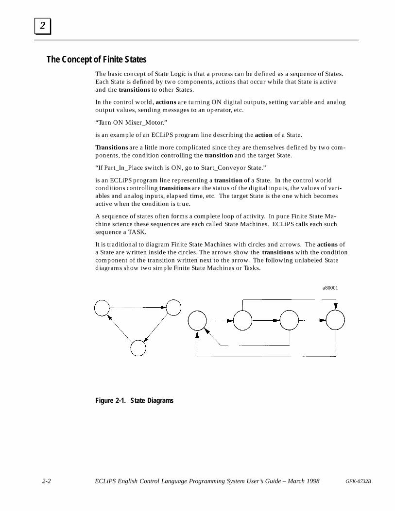
It is traditional to diagram Finite State Machines with circles and arrows. The actions ofa State are written inside the circles. The arrows show the transitions with the conditioncomponent of the transition written next to the arrow. The following unlabeled Statediagrams show two simple Finite State Machines or Tasks.
a80001
Figure 2-1. State Diagrams
2
2-3GFK-0732B Chapter 2 State Logic Control Theory
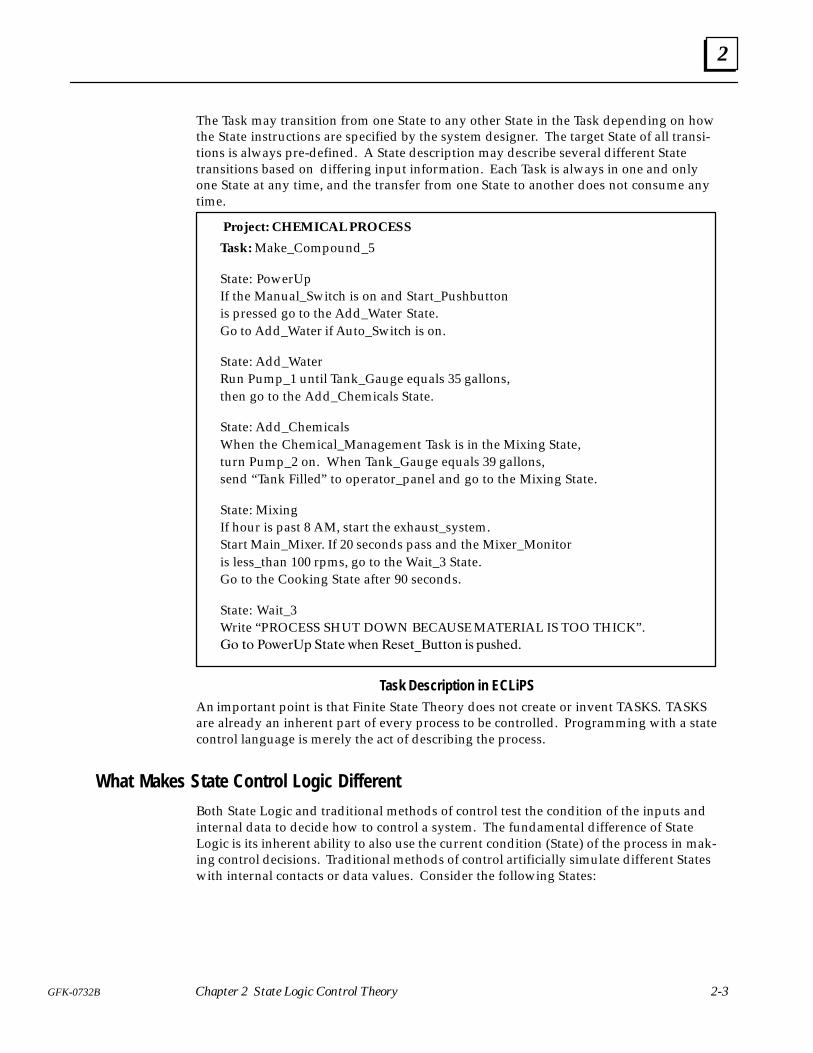
The Task may transition from one State to any other State in the Task depending on howthe State instructions are specified by the system designer. The target State of all transi-tions is always pre-defined. A State description may describe several different Statetransitions based on differing input information. Each Task is always in one and onlyone State at any time, and the transfer from one State to another does not consume anytime.
Project: CHEMICAL PROCESS
Task: Make_Compound_5
State: PowerUpIf the Manual_Switch is on and Start_Pushbuttonis pressed go to the Add_Water State.Go to Add_Water if Auto_Switch is on.
State: Add_WaterRun Pump_1 until Tank_Gauge equals 35 gallons,then go to the Add_Chemicals State.
State: Add_ChemicalsWhen the Chemical_Management Task is in the Mixing State,turn Pump_2 on. When Tank_Gauge equals 39 gallons,send “Tank Filled” to operator_panel and go to the Mixing State.
State: MixingIf hour is past 8 AM, start the exhaust_system.Start Main_Mixer. If 20 seconds pass and the Mixer_Monitoris less_than 100 rpms, go to the Wait_3 State.Go to the Cooking State after 90 seconds.
State: Wait_3Write “PROCESS SHUT DOWN BECAUSE MATERIAL IS TOO THICK” .�� �� ������� ���� � �� ����������� �� ��� ���
Task Description in ECLiPSAn important point is that Finite State Theory does not create or invent TASKS. TASKSare already an inherent part of every process to be controlled. Programming with a statecontrol language is merely the act of describing the process.
What Makes State Control Logic Different
Both State Logic and traditional methods of control test the condition of the inputs andinternal data to decide how to control a system. The fundamental difference of StateLogic is its inherent ability to also use the current condition (State) of the process in mak-ing control decisions. Traditional methods of control artificially simulate different Stateswith internal contacts or data values. Consider the following States:
2
2-4 ECLiPS English Control Language Programming System User’s Guide – March 1998 GFK-0732B
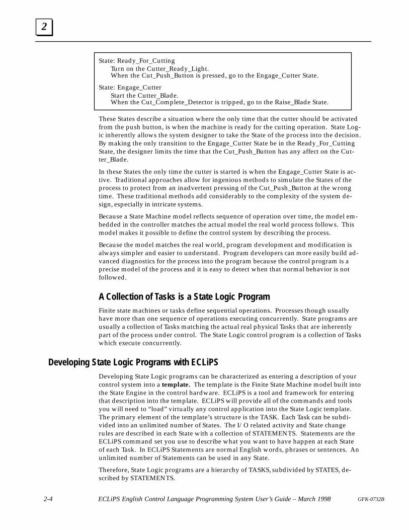
State: Ready_For_CuttingTurn on the Cutter_Ready_Light.When the Cut_Push_Button is pressed, go to the Engage_Cutter State.
State: Engage_CutterStart the Cutter_Blade.When the Cut_Complete_Detector is tripped, go to the Raise_Blade State.
These States describe a situation where the only time that the cutter should be activatedfrom the push button, is when the machine is ready for the cutting operation. State Log-ic inherently allows the system designer to take the State of the process into the decision.By making the only transition to the Engage_Cutter State be in the Ready_For_CuttingState, the designer limits the time that the Cut_Push_Button has any affect on the Cut-ter_Blade.
In these States the only time the cutter is started is when the Engage_Cutter State is ac-tive. Traditional approaches allow for ingenious methods to simulate the States of theprocess to protect from an inadvertent pressing of the Cut_Push_Button at the wrongtime. These traditional methods add considerably to the complexity of the system de-sign, especially in intricate systems.
Because a State Machine model reflects sequence of operation over time, the model em-bedded in the controller matches the actual model the real world process follows. Thismodel makes it possible to define the control system by describing the process.
Because the model matches the real world, program development and modification isalways simpler and easier to understand. Program developers can more easily build ad-vanced diagnostics for the process into the program because the control program is aprecise model of the process and it is easy to detect when that normal behavior is notfollowed.
A Collection of Tasks is a State Logic ProgramFinite state machines or tasks define sequential operations. Processes though usuallyhave more than one sequence of operations executing concurrently. State programs areusually a collection of Tasks matching the actual real physical Tasks that are inherentlypart of the process under control. The State Logic control program is a collection of Taskswhich execute concurrently.
Developing State Logic Programs with ECLiPSDeveloping State Logic programs can be characterized as entering a description of yourcontrol system into a template. The template is the Finite State Machine model built intothe State Engine in the control hardware. ECLiPS is a tool and framework for enteringthat description into the template. ECLiPS will provide all of the commands and toolsyou will need to “ load” virtually any control application into the State Logic template.The primary element of the template’s structure is the TASK. Each Task can be subdi-vided into an unlimited number of States. The I/O related activity and State changerules are described in each State with a collection of STATEMENTS. Statements are theECLiPS command set you use to describe what you want to have happen at each Stateof each Task. In ECLiPS Statements are normal English words, phrases or sentences. Anunlimited number of Statements can be used in any State.
Therefore, State Logic programs are a hierarchy of TASKS, subdivided by STATES, de-scribed by STATEMENTS.
2
2-5GFK-0732B Chapter 2 State Logic Control Theory
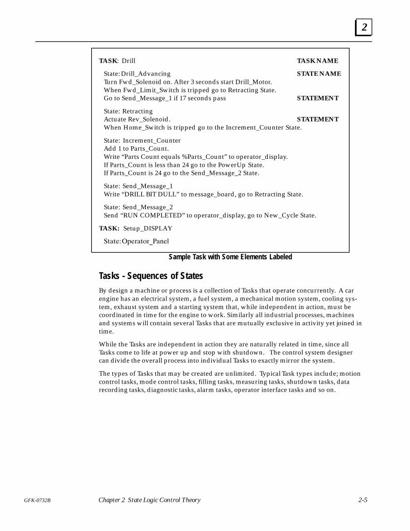
TASK: Drill TASK NAME
State: Drill_Advancing STATE NAME Turn Fwd_Solenoid on. After 3 seconds start Drill_Motor. When Fwd_Limit_Switch is tripped go to Retracting State. Go to Send_Message_1 if 17 seconds pass STATEMENT
State: RetractingActuate Rev_Solenoid. STATEMENTWhen Home_Switch is tripped go to the Increment_Counter State.
State: Increment_CounterAdd 1 to Parts_Count.Write “Parts Count equals %Parts_Count” to operator_display.If Parts_Count is less than 24 go to the PowerUp State.If Parts_Count is 24 go to the Send_Message_2 State.
State: Send_Message_1Write “DRILL BIT DULL” to message_board, go to Retracting State.
State: Send_Message_2Send “RUN COMPLETED” to operator_display, go to New_Cycle State.
TASK: Setup_DISPLAY
��������� ��� ����
Sample Task with Some Elements Labeled
Tasks - Sequences of StatesBy design a machine or process is a collection of Tasks that operate concurrently. A carengine has an electrical system, a fuel system, a mechanical motion system, cooling sys-tem, exhaust system and a starting system that, while independent in action, must becoordinated in time for the engine to work. Similarly all industrial processes, machinesand systems will contain several Tasks that are mutually exclusive in activity yet joined intime.
While the Tasks are independent in action they are naturally related in time, since allTasks come to life at power up and stop with shutdown. The control system designercan divide the overall process into individual Tasks to exactly mirror the system.
The types of Tasks that may be created are unlimited. Typical Task types include; motioncontrol tasks, mode control tasks, filling tasks, measuring tasks, shutdown tasks, datarecording tasks, diagnostic tasks, alarm tasks, operator interface tasks and so on.
2
2-6 ECLiPS English Control Language Programming System User’s Guide – March 1998 GFK-0732B
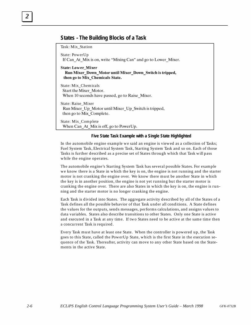
States - The Building Blocks of a TaskTask: Mix_Station
State: PowerUp �� ����� ��$ �� ��� #�� � “�$��� ���” ��� �� � �#����$���
State: Lower_Mixer������ ���������� �������� ����������� �� ����� ��
�� � �� �� ����� ����� ��� �
State: Mix_Chemicals �� ���$���� ���
���� �� ������� ��"� ������� �� � �������$���
State: Raise_Mixer �!� �$������� �� !� �� �$������ #� �� �� �������
��� �� � �$������� ��
State: Mix_Complete ���� ����� ��$ �� ���� �� � ��#�����
Five State Task Example with a Single State Highlighted
In the automobile engine example we said an engine is viewed as a collection of Tasks;Fuel System Task, Electrical System Task, Starting System Task and so on. Each of thoseTasks is further described as a precise set of States through which that Task will passwhile the engine operates.
The automobile engine’s Starting System Task has several possible States. For examplewe know there is a State in which the key is on, the engine is not running and the startermotor is not cranking the engine over. We know there must be another State in whichthe key is in another position, the engine is not yet running but the starter motor iscranking the engine over. There are also States in which the key is on, the engine is run-ning and the starter motor is no longer cranking the engine.
Each Task is divided into States. The aggregate activity described by all of the States of aTask defines all the possible behavior of that Task under all conditions. A State definesthe values for the outputs, sends messages, performs calculations, and assigns values todata variables. States also describe transitions to other States. Only one State is activeand executed in a Task at any time. If two States need to be active at the same time thena concurrent Task is required.
Every Task must have at least one State. When the controller is powered up, the Taskgoes to this State, called the PowerUp State, which is the first State in the execution se-quence of the Task. Thereafter, activity can move to any other State based on the State-ments in the active State.
2
2-7GFK-0732B Chapter 2 State Logic Control Theory
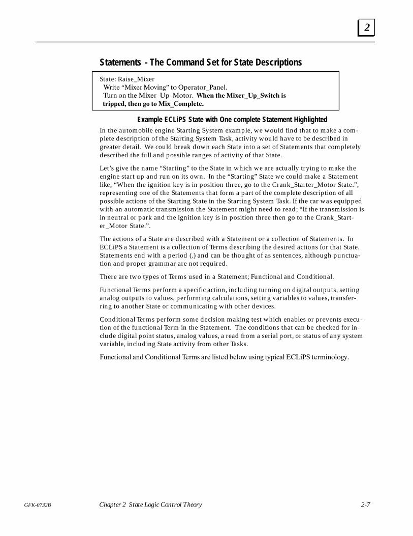
Statements - The Command Set for State Descriptions
State: Raise_Mixer ���� “��"���� ���” �� ��������������
���� �� ��� ��"������������ ���� ��������������� ��
�������� ���� � �� ������������
Example ECLiPS State with One complete Statement HighlightedIn the automobile engine Starting System example, we would find that to make a com-plete description of the Starting System Task, activity would have to be described ingreater detail. We could break down each State into a set of Statements that completelydescribed the full and possible ranges of activity of that State.
Let’s give the name “Starting” to the State in which we are actually trying to make theengine start up and run on its own. In the “Starting” State we could make a Statementlike; “When the ignition key is in position three, go to the Crank_Starter_Motor State.” ,representing one of the Statements that form a part of the complete description of allpossible actions of the Starting State in the Starting System Task. If the car was equippedwith an automatic transmission the Statement might need to read; “ If the transmission isin neutral or park and the ignition key is in position three then go to the Crank_Start-er_Motor State.” .
The actions of a State are described with a Statement or a collection of Statements. InECLiPS a Statement is a collection of Terms describing the desired actions for that State.Statements end with a period (.) and can be thought of as sentences, although punctua-tion and proper grammar are not required.
There are two types of Terms used in a Statement; Functional and Conditional.
Functional Terms perform a specific action, including turning on digital outputs, settinganalog outputs to values, performing calculations, setting variables to values, transfer-ring to another State or communicating with other devices.
Conditional Terms perform some decision making test which enables or prevents execu-tion of the functional Term in the Statement. The conditions that can be checked for in-clude digital point status, analog values, a read from a serial port, or status of any systemvariable, including State activity from other Tasks.
���������� ��� ����������� ����� ��� ������ ����! ����� �#����� ���� ����������#�
2
2-8 ECLiPS English Control Language Programming System User’s Guide – March 1998 GFK-0732B
����� �� ����� � ��� �� �����
�������� ������ ���� �� ��� !���
�� ���� ���
���� ��������� �� ���� ����
����� ���
����
����� ��� ���� ��
������� ����� ����� ����
������
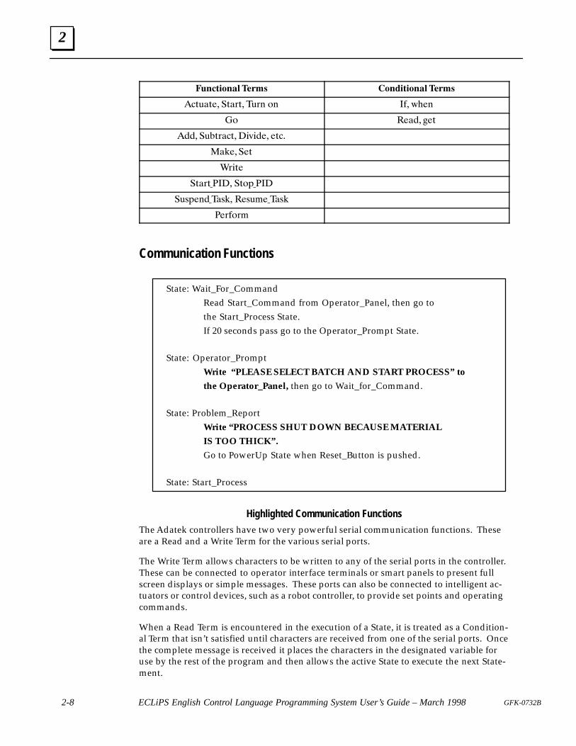
Communication Functions
State: Wait_For_CommandRead Start_Command from Operator_Panel, then go tothe Start_Process State.If 20 seconds pass go to the Operator_Prompt State.
State: Operator_PromptWrite “ PLEASE SELECT BATCH AND START PROCESS” to
the Operator_Panel, then go to Wait_for_Command.
State: Problem_ReportWrite “ PROCESS SHUT DOWN BECAUSE MATERIAL
IS TOO THICK” .
Go to PowerUp State when Reset_Button is pushed.
State: Start_Process
Highlighted Communication Functions
The Adatek controllers have two very powerful serial communication functions. Theseare a Read and a Write Term for the various serial ports.
The Write Term allows characters to be written to any of the serial ports in the controller.These can be connected to operator interface terminals or smart panels to present fullscreen displays or simple messages. These ports can also be connected to intelligent ac-tuators or control devices, such as a robot controller, to provide set points and operatingcommands.
When a Read Term is encountered in the execution of a State, it is treated as a Condition-al Term that isn’t satisfied until characters are received from one of the serial ports. Oncethe complete message is received it places the characters in the designated variable foruse by the rest of the program and then allows the active State to execute the next State-ment.
2
2-9GFK-0732B Chapter 2 State Logic Control Theory
The Read Term can be used to communicate to any serial input device. This would in-clude operator interface devices such as terminals, smart panels, and personal comput-ers. It would also include intelligent sensors such as weigh scales, and the various smartpressure and flow transmitters now sold by various manufactures.
Together the Read and Write Terms make communicating with the operator very power-ful yet simple. It also makes it easy to communicate with intelligent sensors, controllersand other machines that populate the plant or factory.
Any one of the serial ports may be set up for the CCM2 communications protocol. Usingthis protocol enables the State Engine controller to be a slave on a CCM2 network. Typi-cally the protocol is used to communicate with Graphical User Interface Software such asCIMPLICITY, Genesis, The FIX, INTOUCH, Factory Link, Screenware II, etc.
Scan OverviewThe State Engine which executes the control program continuously scans the inputs andthe control program. These scans occur hundreds of times each second. Before eachprogram scan, all of the inputs are scanned, so that each Statement of the programmakes decisions based on the same input information.
During the scan of the program, the active State of each Task is scanned. Each State-ment of a State is scanned in order from the first Statement to the last unless a GO Termis encountered. As soon as a Go is scanned, no more Terms in this State are scanned, andthe scan moves to the active State of the next Task. Another State is scanned during thenext scan sweep.
While scanning a Statement, the scan evaluates all conditional Terms before implement-ing the action described by the functional Terms. If any conditional Term is not satisfiedor false, the scan of this Statement is stopped, the functional Terms are not implemented,and the scan resumes at the next Statement of the State.
The State Engine keeps a table of all digital outputs and flags which are set ON duringthe program scan. Only the outputs set ON by one of the functional Terms in one of theactive States during the scan are set ON, all others are OFF. The real world outputs andflags are set ON at the end of the scan. Therefore, an output does not go OFF during thetransition from one active State to the next when that output is set ON in both States.
This scan discussion is a general overview of the program and I/O parts of the scan. Thereference chapter of this manual has a more detailed discussion of the State Engine scanprocedure.
Interaction Between TasksReturning to the automobile engine State Logic model, we can see that we could de-scribe the entire range of actions of an automobile engine as a collection of Tasks. Fur-ther, we can identify the different States through which each individual Task could passduring operation. Further, we should be able to see how we could use Statements todescribe all of the actions possible for each State and the input conditions that woulddictate which of the possibilities would actually happen.
But the engine wouldn’t work unless we synchronized the timing of Task’s executionwith one another. The Starting System can work perfectly but if the Fuel System Taskdoesn’t provide a squirt of gas into the cylinder during the time the Starting System Taskis in the Starting State the engine won’t run. The same is true of the Electrical SystemTask, which needs to provide voltage to the spark plug at the right time in relation to the
2
2-10 ECLiPS English Control Language Programming System User’s Guide – March 1998 GFK-0732B
Fuel System Task, Mechanical System Task and Starting System Task if the engine is tostart running.
All Tasks have two natural synchronization points, PowerUp and Shutdown. In betweenthe Tasks will execute based on their own instructions and without regard to the otherTasks unless the program developer instructs the Task to do otherwise.
Joining the Tasks in time at various points in the operation of the process under control isnot difficult. There are several techniques for accomplishing this coordination. A goodworking knowledge of how to implement Task interaction is important to the efficientdevelopment of State Logic control programs.
The following are a few examples of situations and techniques for controlling Task inter-action.
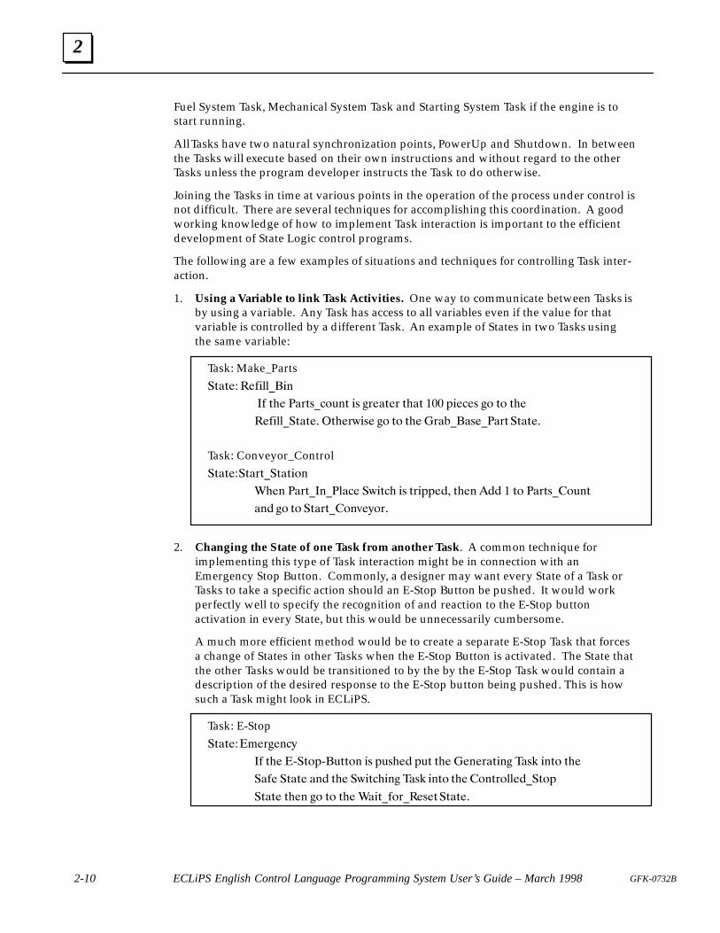
1. Using a Variable to link Task Activities. One way to communicate between Tasks isby using a variable. Any Task has access to all variables even if the value for thatvariable is controlled by a different Task. An example of States in two Tasks usingthe same variable:
Task: Make_Parts�%�%�� ���������
�� %�� ��#%$��!& % �$ �#��%�# %��% ��� "����$ �! %! %��
��������%�%�� %��#(�$� �! %! %�� �#�����$����#% �%�%��
Task: Conveyor_Control�%�%���%�#%��%�%�!
��� ��#%�� ������ �(�%�� �$ %#�""��� %�� ��� � %! ��#%$�!& %
� � �! %! �%�#%�! '�)!#�
2. Changing the State of one Task from another Task. A common technique forimplementing this type of Task interaction might be in connection with anEmergency Stop Button. Commonly, a designer may want every State of a Task orTasks to take a specific action should an E-Stop Button be pushed. It would workperfectly well to specify the recognition of and reaction to the E-Stop buttonactivation in every State, but this would be unnecessarily cumbersome.
A much more efficient method would be to create a separate E-Stop Task that forcesa change of States in other Tasks when the E-Stop Button is activated. The State thatthe other Tasks would be transitioned to by the by the E-Stop Task would contain adescription of the desired response to the E-Stop button being pushed. This is howsuch a Task might look in ECLiPS.
Task: E-Stop �%�%����#�� �)
�� %�� *�%!"*�&%%! �$ "&$��� "&% %�� �� �#�%� � ��$� � %! %��
���� �%�%� � � %�� �(�%��� � ��$� � %! %��! %#!������%!"
�%�%� %�� �! %! %�� ���%��!#���$�%�%�%��
2
2-11GFK-0732B Chapter 2 State Logic Control Theory
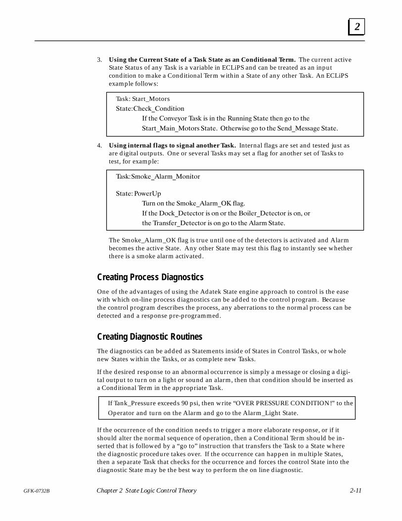
3. Using the Current State of a Task State as an Conditional Term. The current activeState Status of any Task is a variable in ECLiPS and can be treated as an inputcondition to make a Conditional Term within a State of any other Task. An ECLiPSexample follows:
Task: Start_Motors�#�#�������������#���
� #�� ���%�'�! ��"� �" �� #�� �$����� �#�#� #��� �� #� #��
�#�!#��������#�!" �#�#�� �#��!&�"� �� #� #�� �������""��� �#�#��
4. Using internal flags to signal another Task. Internal flags are set and tested just asare digital outputs. One or several Tasks may set a flag for another set of Tasks totest, for example:
��"�����������!������#�!
�#�#�� �&�!�
�$!� �� #�� ���������!��� �����
� #�� �������#��#�! �" �� �! #�� �����!���#��#�! �" ��� �!
#�� �!��"��!���#��#�! �" �� �� #� #�� ���!� �#�#��
The Smoke_Alarm_OK flag is true until one of the detectors is activated and Alarmbecomes the active State. Any other State may test this flag to instantly see whetherthere is a smoke alarm activated.
Creating Process DiagnosticsOne of the advantages of using the Adatek State engine approach to control is the easewith which on-line process diagnostics can be added to the control program. Becausethe control program describes the process, any aberrations to the normal process can bedetected and a response pre-programmed.
Creating Diagnostic RoutinesThe diagnostics can be added as Statements inside of States in Control Tasks, or wholenew States within the Tasks, or as complete new Tasks.
If the desired response to an abnormal occurrence is simply a message or closing a digi-tal output to turn on a light or sound an alarm, then that condition should be inserted asa Conditional Term in the appropriate Task.
If Tank_Pressure exceeds 90 psi, then write “OVER PRESSURE CONDITION!” to the Operator and turn on the Alarm and go to the Alarm_Light State.
If the occurrence of the condition needs to trigger a more elaborate response, or if itshould alter the normal sequence of operation, then a Conditional Term should be in-serted that is followed by a “go to” instruction that transfers the Task to a State wherethe diagnostic procedure takes over. If the occurrence can happen in multiple States,then a separate Task that checks for the occurrence and forces the control State into thediagnostic State may be the best way to perform the on line diagnostic.
2
2-12 ECLiPS English Control Language Programming System User’s Guide – March 1998 GFK-0732B
Because the control program written in ECLiPS is self descriptive, and each State de-scribes what should be happening and what should happen next, it is easy to insert diag-nostics after the control program is finished.
In addition to the ability to add diagnostic logic with Statements, States and diagnosticTasks, ECLiPS also contains several functions to help the user automate the process ofadding them.
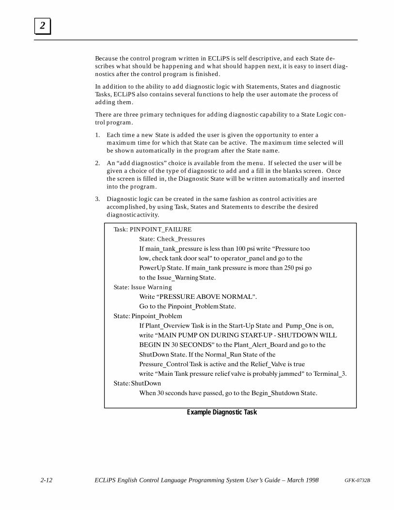
There are three primary techniques for adding diagnostic capability to a State Logic con-trol program.
1. Each time a new State is added the user is given the opportunity to enter amaximum time for which that State can be active. The maximum time selected willbe shown automatically in the program after the State name.
2. An “add diagnostics” choice is available from the menu. If selected the user will begiven a choice of the type of diagnostic to add and a fill in the blanks screen. Oncethe screen is filled in, the Diagnostic State will be written automatically and insertedinto the program.
3. Diagnostic logic can be created in the same fashion as control activities areaccomplished, by using Task, States and Statements to describe the desireddiagnostic activity.
Task: PINPOINT_FAILUREState: Check_Pressures �# *�&+�0�+(�-."//1." &/ )"// 0%�+ ��� -/& 3.&0" “�."//1." 0,,
),3� %" ( 0�+( !,,. /"�)” 0, ,-".�0,.�-�+") �+! $, 0, 0%"
�,3".�- �0�0"� �# *�&+�0�+( -."//1." &/ *,." 0%�+ ��� -/& $,
0, 0%" �//1"���.+&+$�0�0"�
State: Issue Warning�.&0" “������������ �����” �
�, 0, 0%" �&+-,&+0��.,�)"*�0�0"�
�0�0" �&+-,&+0��.,�)"*
�# �)�+0��2".2&"3 ��/( &/ &+ 0%" �0�.05�- �0�0" �+! �1*-��+" &/ ,+�
3.&0" “��� ���� �� ����� ����5�� 5 ���� ��� ����
����� �� �� ����� �” 0, 0%" �)�+0�)".0��,�.! �+! $, 0, 0%"
�%10 ,3+ �0�0"� �# 0%" �,.*�)��1+ �0�0" ,# 0%"
�."//1."��,+0.,) ��/( &/ � 0&2" �+! 0%" �")&"#���)2" &/ 0.1"
3.&0" “��&+ ��+( -."//1." .")&"# 2�)2" &/ -.,���)4 '�**"!” 0, �".*&+�)���
�0�0"�%10 ,3+
�%"+ �� /" ,+!/ %�2" -�//"!� $, 0, 0%" �"$&+��%10!,3+ �0�0"�
Example Diagnostic Task
3 section level 1 1figure bi level 1 table_big level 1
3-1GFK-0732B
Chapter 3 Creating A Control Program
This chapter presents the fundamental concepts of how a control program can be builtusing ECLiPS. Every designer will develop his own style in using ECLiPS. ECLiPS isdesigned to support and even to encourage personal or corporate program developmentstyles. Initially however, it is suggested that the following procedure be followed increating your first control system program with ECLiPS. This procedure is split into twosteps:
1. Outline the Application
2. Write the Program
3
3-2 ECLiPS English Control Language Programming System User’s Guide – March 1998 GFK-0732B
Outline the Application
In this step the control problem is analyzed using a top down design strategy where thecomponents of the main problem are identified at the top level and then each of thesecomponents is broken down into its separate parts. This decomposition of the problemcontinues until the application is completely described. The State Logic Control modelinvites top down design because of the hierarchy of its elements, Tasks, States, and State-ments as described in the previous chapter. There are several different formats to aid inthe top down design process including structure charts and structured flow charts, butwe use a simple outline approach.
Identify the TasksThe goal of this step is to identify the Tasks of the application. We start at the highestlevel, decomposing the problem into its general components. See the discussion onTasks in the State Logic Control Theory chapter of this manual.
Think of the independent operations which must be accomplished to achieve goals ofthe application. The natural separations of activity often become Tasks.
The goal is to decompose the problem into parts that can be defined as sequences of I/Ooperation. Any cycles which repeat even with some variations are prime candidates tobe Tasks. An important concept for identifying Tasks is that Tasks are a set of sequentialoperations. Events which occur in parallel or concurrently should be in separate Tasks.
These main sections of the outline should be general descriptive phrases such as:
Bore CylinderLoad BoilerFill VatRetrieve Part
At this stage the goal is to just describe the application not force some solution. Some ofthe independent Tasks are quite obvious, others which require interaction with otherTasks are more difficult to identify at first. This is usually a repetitive process where orig-inal efforts must be adjusted as the outline progresses. As with most activities, proficien-cy increases with the number of efforts.
If you are having trouble identifying the Tasks in your particular application pleasedon’t hesitate to call our customer support line at (800) 323-3343. You may call even ifyou don’t have a specific question but would simply like to discuss the concept of Taskarchitecture.
Identify The StatesOnce the Tasks are determined, then the States of each Task should be identified. TheStates describe the actual condition the outputs and responses to inputs at a certainpoint in the control process. The States form the control sequence and are really a pic-ture of how this piece of the process (Task) should behave. See the discussion of Statesin the State Logic Control Theory chapter of this manual.
At this point in the design stage the goal is to determine that the correct action can beaccomplished with the chosen Task architecture. Simply give each State a descriptive
3
3-3GFK-0732B Chapter 3 Creating A Control Program
name fitting the major attribute of the activity that takes place when that State becomesactive. Typical State names are:
Send MessageAdd WaterRaise DrillStart Motor
State names identify the general action of the State. The specific actions and the transi-tions are specified in the Statements.
Identify the StatementsThis level is the most specific level of the outline. Statements specify detailed actionswhich are to occur while this State is active, and the transitions to other States. See thediscussion of Statements in the State Logic Control chapter of this manual.
The actions specified by Statements include digital outputs that are to be ON, changes inanalog output values, changes in variable values, and messages to be sent. Examples ofactions as specified in Statements are:
Turn ON Pump 5.Start Mixer Motor.Write “Operation complete” to Operator.Add 1 to Parts Count.Turn ON Forward Solenoid.
Statements also specify the transitions of a State. Both the condition for transition andthe target State are identified. The status of digital inputs, values of analog inputs andvariables, and elapsed time are used to specify conditions for a transition. State namesspecify the target State that becomes active when the condition is true. Typical transi-tions as they would appear in an outline are:
If Forward Limit Switch is ON, go to the Drill State.If Vat Temperature is less than 45 degrees go to Raise Temperature State.When 10 Seconds have Passed, go to Raise Mixer State.If Part in Place Switch is ON and Manual Switch is OFF, go to Move State.
Statements are often complete English sentences, since very specific operations are spe-cified at this level of the outline. In fact, feel free to specify Statements in any comfort-able format. Some additional examples combine the State actions with the transitions:
Run Mixer Motor. When 5 seconds have elapsed, then go to Raise Mixer State.Write “Drill Bit is Dull” to operator, then go to Retract Drill State.Read Command from Operator, then go to Report State.
Writing The Program
With this outline in place, the ECLiPS program is almost completely written. The fin-ished program is very close to the outline.

3
3-4 ECLiPS English Control Language Programming System User’s Guide – March 1998 GFK-0732B
There may be some changes to the outline because of some naming conventions for howTask, State, and some other names are entered into the program. ECLiPS can not pro-vide for the full expressiveness of the English language so some of the sentenceconstructions may have to be changed, although many alternative structures and theability to make custom changes to ECLiPS are provided. Also, the outline is in a generalformat with no specific reference to the actual I/O of the system so that the wording ofthe outline usually becomes more specific in the program.
To write the program the Tasks, States, and Statements of the outline are entered into theproject using the ECLiPS editor which is active whenever ECLiPS is in Program Mode.Another part of creating the program is specifying I/O names and circuit configurations.Defining the I/O may be done before, after, or during the writing of the program.
Using English Names in the ECLiPS ProgramWhen you start a new program, ECLiPS asks for the name of the first Task. After thename is entered, ECLiPS starts the program for you by writing the Task keyword fol-lowed by a colon and the Task name. ECLiPS also writes the first State name, “PowerUp”into the program. Tasks, States, I/O points and variables can all be assigned Englishnames. Names can be as brief and code like or as descriptive as you wish.
Clever, descriptive names that fit well to the primary attribute of that State activity isstrongly encouraged. This will pay dividends in future program modifying, clear docu-mentation and easier troubleshooting.
Further, good descriptive names will enhance the quality of the automatic diagnosticsthat can be created by linking Task, State and I/O names together for automatic diagnos-tic output information.
Each name can have up to a twenty characters. These characters may be letters, num-bers, or the underscore character (_). Names must begin with a letter. The name mustbe a continuous string of characters, i.e., no spaces are allowed.
Because ECLiPS uses the space character as a way to tell where one word ends and thenext begins, as we normally do in written English, a name can not contain a space. Toconstruct a multiple word name for descriptive purposes the designer should use theunderscore character (_) to separate words or use uppercase to start every new word.
Table_MovementTableMovement
Naming TasksTask names are arbitrary. It is suggested that Task names be descriptive of the activitythey represent. This descriptive use of names means clearer documentation and theability to create automatic diagnostic output messages by combining Task, State and I/Onames to make complete messages.
A Task may be added to the program by using the “Add a New Task” option from theAdd Menu or just typing in the Task keyword followed by a colon and the Task name.Each Task is assigned a name as it is built and each Task must have a unique name. Thisname appears at the beginning of every Task. Every time the designer wants to refer tothe Task using ECLiPS such as in writing other Task sequences, during debugging or dur-ing diagnostics development, the English Task name should be used.

3
3-5GFK-0732B Chapter 3 Creating A Control Program
Naming StatesEach Task contains one or more States. Similar to Tasks, a name is assigned to everyState of the program either through the Add menu or directly into the program usingthe ECLiPS editor. Once assigned, these names are used when performing any func-tions associated with States while using ECLiPS.
Each Task always begins execution in the PowerUp State when the program starts. As areminder as to which State will begin the sequence when power is applied to the con-troller, the first State of every Task must be named PowerUp.
While every Task in a controller must have a unique name to differentiate it from theothers, States in different Tasks may have the same name. All States within one commonTask must have a unique name, but a State in one Task can be named the same as one ina different Task.
As with Tasks, names chosen for the States should be descriptive. By using combinationsof words that describe something unique to the State, such as the action performed orfunction of the State, the program becomes self documenting. Using descriptive namesmakes it possible for people other than the original designer to use and modify a se-quence at a later date with minimum learning time spent trying to understand the pro-gram.
Naming I/O Circuits, Variables, and Internal FlagsEach input and output from and to the field enters and leaves the controller throughsome particular hardware card. A name is given to each of these I/O points. All refer-ences to I/O circuits use the assigned name.
Names are also used for variables and internal flags. All names must be unique. A vari-able must not have the same name as a State or a flag must not use the name of a Task.The only exception to this rule is that States in different Tasks may use duplicate names.
The English name should be descriptive and can be made up of several words attachedby the underscore character. ECLiPS allows the user to define I/O points or other nameother elements of the program at any time during the programming process.
Statement Structures
The greatest difference between the outline and the ECLiPS program is in the expressionof the Statements. This section describes how to express the Statements in an ECLiPSprogram.
State: Drill_Advancing Turn Fwd_Solenoid on. After 3 seconds pass, start Drill_Motor. When Fwd_Limit_Switch is tripped go to the Retracting State. If 17 seconds pass, go to the Send_Message State.
Example ECLiPS State with Four StatementsMost States consist of several Statements that describe what action is to happen whilethe Task is in that State, what conditions will cause a transfer, and to what State the Tasktransfers to. With ECLiPS these Statements are written in descriptive English generallybut not necessarily consistent with the rules of English grammar. Statements are short
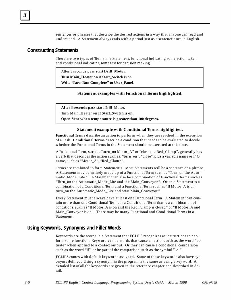
3
3-6 ECLiPS English Control Language Programming System User’s Guide – March 1998 GFK-0732B
sentences or phrases that describe the desired actions in a way that anyone can read andunderstand. A Statement always ends with a period just as a sentence does in English.
Constructing StatementsThere are two types of Terms in a Statement, functional indicating some action takenand conditional indicating some test for decision making.
After 3 seconds pass start Drill_Motor.
Turn Main_Heater on if Start_Switch is on.Write “ Parts Run Complete” to User_Panel.
Statement examples with Functional Terms highlighted.
After 3 seconds pass start Drill_Motor.Turn Main_Heater on if Start_Switch is on.
Open Vent when temperature is greater than 100 degrees.
Statement example with Conditional Terms highlighted.Functional Terms describe an action to perform when they are reached in the executionof a Task. Conditional Terms describe a condition that needs to be evaluated to decidewhether the Functional Terms in the Statement should be executed at this time.
A Functional Term, such as “ turn_on Motor_A” or “close the Red_Clamp” , generally hasa verb that describes the action such as, “ turn_on” , “close” , plus a variable name or I/Oname, such as “Motor_A” , “Red_Clamp” .
Terms are combined to form Statements. Most Statements will be a sentence or a phrase.A Statement may be entirely made up of a Functional Term such as “Turn_on the Auto-matic_Mode_Lite.” . A Statement can also be a combination of Functional Terms such as“Turn_on the Automatic_Mode_Lite and the Main_Conveyor.” . Often a Statement is acombination of a Conditional Term and a Functional Term such as “ If Motor_A is onturn_on the Automatic_Mode_Lite and start Main_Conveyor.” .
Every Statement must always have at least one Functional Term. A Statement can con-tain more than one Conditional Term, or a Conditional Term that is a combination ofconditions, such as “ If Motor_A is on and the Red_Clamp is closed” or “ If Motor_A andMain_Conveyor is on” . There may be many Functional and Conditional Terms in aStatement.
Using Keywords, Synonyms and Filler WordsKeywords are the words in a Statement that ECLiPS recognizes as instructions to per-form some function. Keyword can be words that cause an action, such as the word “ac-tuate” when applied to a contact output. Or they can cause a conditional comparisonsuch as the word “ if” , or be part of the comparison such as the symbol ” > “ .
ECLiPS comes with default keywords assigned. Some of these keywords also have syn-onyms defined. Using a synonym in the program is the same as using a keyword. Adetailed list of all the keywords are given in the reference chapter and described in de-tail.
3
3-7GFK-0732B Chapter 3 Creating A Control Program
ECLiPS also comes with several filler words such as “ the” or “a” defined. Filler wordshave no meaning to the control program. The sole purpose of filler words is to makeprogram Statements more readable and understandable. The user can place filler wordsanywhere in the Statement. Commas and other punctuation may also be used for claritywithout effecting program execution. The only punctuation which has meaning is theperiod (.) and the exclamation mark (!). The exclamation mark is used to document oradd comments to the control program.
Keywords are the vocabulary of ECLiPS and together with filler words make it possibleto easily write understandable descriptions that are the control program. This vocabu-lary may be changed to suit any desired convention. All of the keywords, synonyms,and filler words may be changed. ECLiPS can therefore be configured so that the pro-gram is written in a foreign language.
A menu based window function allows the user to make these assignments at any timeduring an ECLiPS programming session. In addition, another menu based windowfunction allows the user to see a list of all synonyms previously assigned and to selectone to enter into the program.
Use the flexibility to create a language that fits the terminology of the industry, or plant,etc. where ECLiPS is to be used. The written ECLiPS programs become even clearer toall involved with operating and maintaining the plant as they use the English names forthe process points and the local terminology for the actions and descriptions.
Using VariablesStatements manipulate variables in addition to controlling the I/O. At times the applica-tion requires responses to values other than those represented by real field sensors. Ex-amples of this might be the number of parts built during a shift, the flow through a pipecalculated based upon the pressure drop across the pipe, the style of part being built thisproduction run, etc.
Items stored in variables are the results of calculations, totals that are being accumulatedover time, something that must be remembered from one time period to the next, andconstants that may be changed or tuned. Each variable is assigned a name during pro-gram development.
Once created each variable is available to be shared between Tasks and States withinTasks. One State may assign a value to the variable and another State (or the same Stateat a later time period) uses the value of the variable in making a decision. Once a vari-able is assigned a value, that variable maintains that value until a program Statementassigns a new value to that variable. Variables may be configured to hold their valueover a halt or power cycle.
When using ECLiPS to write programs or monitor running controllers, or generate diag-nostics, the user needs to only refer to the variable by its English name. Remember thatchoosing descriptive names for variables helps to make the program self documenting.
The different variable types are listed below:
Integer Variables
This type of variable represents a whole number from +32767 to –32768. Integervariables have many uses including counts, menu choices, and item quantities.
Integer variables can also be used as logical variables, or variables that have onlytwo possible values, either 1 or 0. Variables used in this manner can be thought
3
3-8 ECLiPS English Control Language Programming System User’s Guide – March 1998 GFK-0732B
of as true or false, on or off, etc. Using integer variables in this manner differsfrom using flags, since flags are ON only when a State turning them On isactive. On the other hand a variable maintains its value independent of whichState is active.
Internal Flag
Internal flags are variables that act like digital outputs, but do not produce anyphysical output from the controller. An internal flag can be set true by a State in oneTask and then checked by a State in another Task. These flags can be used tocoordinate the actions of different independent Tasks.
An internal flag is like a digital output in that if an active State is not setting it truethe controller will automatically turn it OFF.
Floating Point Variable
This variable type is used to store numbers that are not whole numbers or numbersoutside the range of integer variables. When variables are needed with a mathfunction, generally it should be a real variable.
String Variable
This variable type stores a collection or “string” of characters. These characters canbe any alpha numeric or control character represented by an ASCII code. This typeof variable is a little more complicated and is used mainly in accepting inputs orcreating outputs to serial communication devices.
Character Variable
Character variables store one single ASCII character. This type of variable isespecially useful for operator interfaces when the operator must enter a singlecharacter.
Time Variables
The time variables are used to view or change the values of the Real Time Clock.The time variables are second, minute, hour, day, day of the week, and month. Usethese variables to set the clock or to check the current time.
Register Variables
Register Variables are stored in the CPU %R memory locations and may be eitherfloating point, integer, or character data type. Register variables are used when aCPU Ladder Logic Program or some other module in the Series 90 system needs toaccess the data used in the State Logic program.
Program ScanThe State Engine operating system is a scanning system. The scan cycle starts at the startof the program, scanning the active State of every Task. During program execution thereis always one and only one State active in each Task. The operating system completes ascan of the program hundreds of times every second.
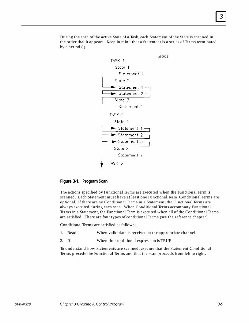
3
3-9GFK-0732B Chapter 3 Creating A Control Program
During the scan of the active State of a Task, each Statement of the State is scanned inthe order that it appears. Keep in mind that a Statement is a series of Terms terminatedby a period (.).
a80002
Figure 3-1. Program Scan
The actions specified by Functional Terms are executed when the Functional Term isscanned. Each Statement must have at least one Functional Term, Conditional Terms areoptional. If there are no Conditional Terms in a Statement, the Functional Terms arealways executed during each scan. When Conditional Terms accompany FunctionalTerms in a Statement, the Functional Term is executed when all of the Conditional Termsare satisfied. There are four types of conditional Terms (see the reference chapter).
Conditional Terms are satisfied as follows:
1. Read - When valid data is received at the appropriate channel.
2. If - When the conditional expression is TRUE.
To understand how Statements are scanned, assume that the Statement ConditionalTerms precede the Functional Terms and that the scan proceeds from left to right.

3
3-10 ECLiPS English Control Language Programming System User’s Guide – March 1998 GFK-0732B
a80003
Figure 3-2. Statement Scan
The Statements of a State are executed in the order that they are written into the pro-gram. Functional Terms of Statements with no Conditional Terms are always executed.Conditional Terms in Statements control whether or not the Functional Terms in thoseStatements are executed. If all of the Conditional Terms are satisfied, the FunctionalTerms are executed. If any of the Conditional Terms are not satisfied and ConditionalTerms, the Functional Terms are not executed. For simplicity this rule assumes that theConditional Terms are ANDed together. See the reference chapter about combiningConditional Terms using the AND and OR logical keywords.
The Statements are executed one at a time. In this manner every Statement of the activeState is evaluated.
There are two types of Functional Terms that can prevent the execution of the rest of theStatements in a State. One is the Halt command which stops program execution. Theother is the “go to ...” command, which immediately causes another State to become theactive State. No Terms in a State are scanned after a GO is scanned in that State.
If Start_Pushbutton is pushed, go to Start_Up State.Write “Press Start Push Button Now!!” .If 30 seconds have passed, go to the Restart_Buzzer State.
This series of Statements causes the Start_Up State to become the active State when theinput represented by Start_Pushbutton name is true. When GO Term is scanned, allTerms or Statements following this Term are not executed and at the next controllercycle, the scan of this Task starts at the first Statement of the Start_Up State.
During the program scan any changes to variables are made immediately. Therefore, avariable change in one Task is visible by the rest of the program during the same scan.On the other hand, digital I/O and Flag and analog values are made at the end of thescan. Therefore, if one Task makes a change to the condition of a digital output or Flag,the condition cannot be tested by another Task until the next scan through the program.
4 section level 1 1figure bi level 1 table_big level 1
4-1GFK-0732B
Chapter 4 Programming Tutorial
This chapter presents a step by step procedure for writing a control program for a specif-ic application. Follow along duplicating each keyboard entry on your own computer.Watch for the text displayed in bold italics, these are the lines that you should enter.
To best understand this tutorial, you should first read the chapters on State Logic Con-trol Theory and Creating a Control Program, chapters 2 and 3.
Tutorial Procedure
All that is required to follow along with this tutorial is a computer with ECLiPS installed.All of the examples in this chapter deal with programming and can be executed withoutconnecting ECLiPS to a State Logic Processor. On the other hand, the Online Tutorialchapter describing run-time debugging and monitoring functions, does require ECLiPSto be connected to an SLP.
The programming procedure described in the Creating an ECLiPS Control Program chapter, is used in this tutorial. The first step in creating a control program is to write ageneral outline of the application:
� Identify the Highest Level of the Outline - The Tasks
� Decompose each Task into its Sequence of States
� Write the Statements which Describe the Activity of Each State
The next step is to write the control program from this outline:
� Modify the outline to specify Names of Program Elements
� Define these Names and Configure the I/O Circuits
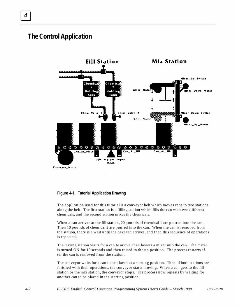
4
4-2 ELCiPS English Control Language Programming System User’s Guide – March 1998 GFK-0732B
The Control Application
Figure 4-1. Tutorial Application Drawing
The application used for this tutorial is a conveyor belt which moves cans to two stationsalong the belt. The first station is a filling station which fills the can with two differentchemicals, and the second station mixes the chemicals.
When a can arrives at the fill station, 20 pounds of chemical 1 are poured into the can.Then 10 pounds of chemical 2 are poured into the can. When the can is removed fromthe station, there is a wait until the next can arrives, and then this sequence of operationsis repeated.
The mixing station waits for a can to arrive, then lowers a mixer into the can. The mixeris turned ON for 10 seconds and then raised to the up position. The process restarts af-ter the can is removed from the station.
The conveyor waits for a can to be placed at a starting position. Then, if both stations arefinished with their operations, the conveyor starts moving. When a can gets to the fillstation or the mix station, the conveyor stops. The process now repeats by waiting foranother can to be placed in the starting position.
4
4-3GFK-0732B Chapter 4 Programming Tutorial
Outline the Application
The first step in creating an ECLiPS program as shown in chapter 3 is to outline the ap-plication using a top down approach. The control problem is first described in generalterms. These terms are successively broken down into more specific details. First Tasksare identified, then each Task is defined by a sequence of States, and each State is de-fined by a collection of Statements.
Identify the TasksA Task is a sequence of events or steps. (See the discussions about Tasks in the State Log-ic Control Theory and Creating a Control Program chapters). Several Tasks are used todescribe sequences which execute during the same time period yet are independentfrom each other. Tasks describe sequential activity which may occur in parallel with oth-er Task activities.
In choosing the Tasks for this problem, notice that the fill station and the mix station op-erate completely independently from each other. No occurrence at one station has anyeffect on the operation of the other station. The operation of each station can also bedescribed as a sequence of events. Therefore, the operation of each station is chosen tobe a separate Task.
The operation of the conveyor is chosen as the third Task, since its operation can be de-scribed as a sequence of events and some of the actions occur simultaneously to the ac-tions of both stations.
�� ��� ���� �
��� �� ���� �
���� � ��� �
Outline with Tasks OnlySince each Task operates concurrently with the other Tasks, the order of Tasks in the out-line has no meaning.
Identify the StatesNow each Task is decomposed into the States which define the Task. The Tasks are de-fined in the order that they appear in the outline. (See the chapters on State Logic Con-trol Theory and Creating a Control Program for more information about States).
Fill Station StatesLooking at the Fill Station Task sequence of events, we see that there are four distinctsteps, each defined by the status of the process at that point in time.
Step 1: On power up the fill station waits for a can to arrive at the station. When a canarrives, the status of the process changes.
Step 2: Chemical 1 starts to pour into the can. Chemical 1 continues to pour into the canuntil 20 pounds of chemical 1 are in the can.
Step 3: Now chemical 2 starts pouring into the can. The next State of the process startswhen 10 pounds of chemical 2 are in the can.

4
4-4 ELCiPS English Control Language Programming System User’s Guide – March 1998 GFK-0732B
Step 4: The last State is waiting for the can to be removed from the fill station. Whenthe can is removed the procedure repeats by starting again with step 1.
When the process starts, the fill station Task waits for a can to arrive at the station. Nor-mally this State might be called Wait for Can, but since this is the State that is active onstart up it is named Power Up. Every Task must have a State named Power Up which isactive when the program starts execution.
The other States are given brief descriptive names: Pour Chemical 1, Pour Chemical 2,and Wait for Can Removal. With the naming of the Fill Station States, the outline at thisstage is as follows:
� ��� �������
�� �� �� ��
�� ���� �������� �
�� ���� �������� �
�� ���� ��� ��� ������
� ��! �������
� �����"��
Outline with Tasks and Fill Station States
Mix Station StatesThe Mix Station has five distinct steps which describe the sequence of operations at thisstation.
Step 1: During this step the station is waiting for a can to arrive at the station. After acan arrives the next step starts.
Step 2: Now the mixer is lowered into the can. When the mixer is down, the processgoes to the next step.
Step 3: The action of this step is to mix the contents of the can. The process goes to thenext step after the contents have been mixed for 10 seconds.
Step 4: During this step the mixer is raised. After the mixer is all the way up the last stepbegins.
Step 5: The final State waits for the can to be removed. When a can is removed the pro-cedure repeats by going to step 1 again.
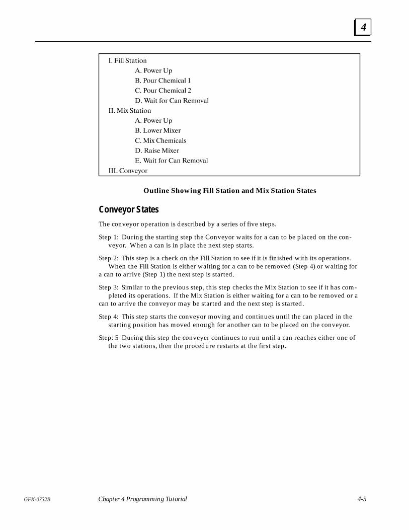
4
4-5GFK-0732B Chapter 4 Programming Tutorial
�� ��� � � ���
�� ��#�� ��
�� ��!� �������� �
�� ��!� �������� �
�� ��� ��� ��� ����"��
��� �$ � � ���
�� ��#�� ��
�� ��#�� �$��
�� �$ ���������
�� ����� �$��
� ��� ��� ��� ����"��
���� ���"�%��
Outline Showing Fill Station and Mix Station States
Conveyor StatesThe conveyor operation is described by a series of five steps.
Step 1: During the starting step the Conveyor waits for a can to be placed on the con-veyor. When a can is in place the next step starts.
Step 2: This step is a check on the Fill Station to see if it is finished with its operations.When the Fill Station is either waiting for a can to be removed (Step 4) or waiting for
a can to arrive (Step 1) the next step is started.
Step 3: Similar to the previous step, this step checks the Mix Station to see if it has com-pleted its operations. If the Mix Station is either waiting for a can to be removed or a
can to arrive the conveyor may be started and the next step is started.
Step 4: This step starts the conveyor moving and continues until the can placed in thestarting position has moved enough for another can to be placed on the conveyor.
Step: 5 During this step the conveyer continues to run until a can reaches either one ofthe two stations, then the procedure restarts at the first step.
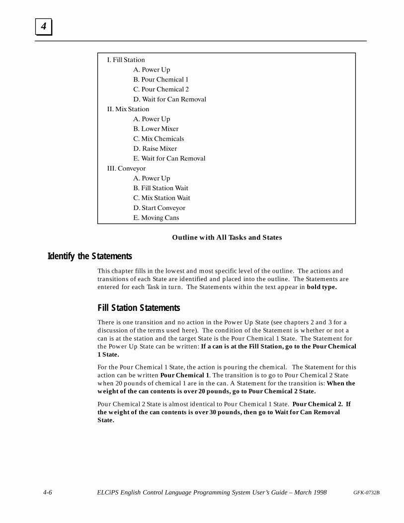
4
4-6 ELCiPS English Control Language Programming System User’s Guide – March 1998 GFK-0732B
�� ��� �!�!���
�� ��$�� ��
�� ��"� �������� �
�� ��"� �������� �
�� ���! ��� ��� ����#��
��� �% �!�!���
�� ��$�� ��
�� ��$�� �%��
�� �% ��������
�� ��� � �%��
� ���! ��� ��� ����#��
���� ���#�&��
�� ��$�� ��
�� ��� �!�!��� ���!
�� �% �!�!��� ���!
�� �!��! ���#�&��
� �#��� ���
Outline with All Tasks and States
Identify the Statements
This chapter fills in the lowest and most specific level of the outline. The actions andtransitions of each State are identified and placed into the outline. The Statements areentered for each Task in turn. The Statements within the text appear in bold type.
Fill Station StatementsThere is one transition and no action in the Power Up State (see chapters 2 and 3 for adiscussion of the terms used here). The condition of the Statement is whether or not acan is at the station and the target State is the Pour Chemical 1 State. The Statement forthe Power Up State can be written: If a can is at the Fill Station, go to the Pour Chemical1 State.
For the Pour Chemical 1 State, the action is pouring the chemical. The Statement for thisaction can be written Pour Chemical 1. The transition is to go to Pour Chemical 2 Statewhen 20 pounds of chemical 1 are in the can. A Statement for the transition is: When theweight of the can contents is over 20 pounds, go to Pour Chemical 2 State.
Pour Chemical 2 State is almost identical to Pour Chemical 1 State. Pour Chemical 2. Ifthe weight of the can contents is over 30 pounds, then go to Wait for Can RemovalState.
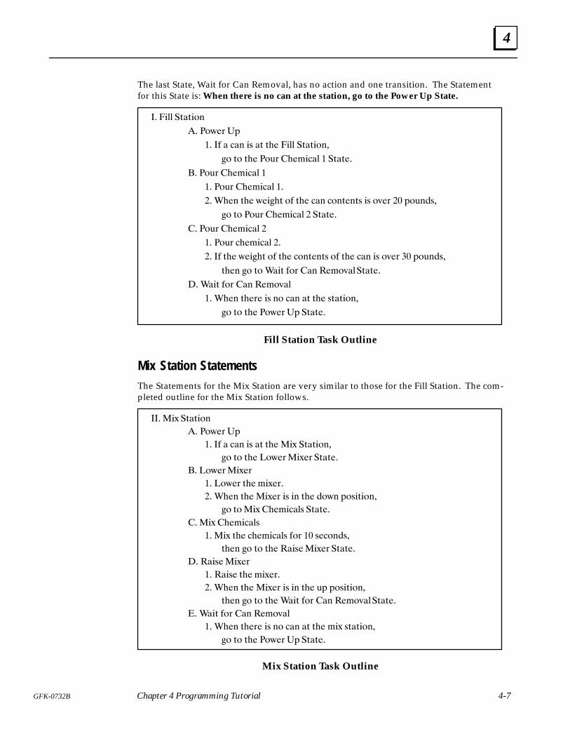
4
4-7GFK-0732B Chapter 4 Programming Tutorial
The last State, Wait for Can Removal, has no action and one transition. The Statementfor this State is: When there is no can at the station, go to the Power Up State.
�� ��� �%�%�!
�� �!(�# �"
�� �� � �� �$ �% %�� ��� �%�%�! �
�! %! %�� �!&# ������� � �%�%��
� �!&# ������� �
�� �!&# ������� ��
�� ��� %�� (����% !� %�� �� �! %� %$ �$ !'�# �� "!& �$�
�! %! �!&# ������� � �%�%��
� �!&# ������� �
�� �!&# �������� ��
�� �� %�� (����% !� %�� �! %� %$ !� %�� �� �$ !'�# �� "!& �$�
%�� �! %! ���% �!# � ���!'���%�%��
�� ���% �!# � ���!'��
�� ��� %��#� �$ ! �� �% %�� $%�%�! �
�! %! %�� �!(�#�" �%�%��
Fill Station Task Outline
Mix Station StatementsThe Statements for the Mix Station are very similar to those for the Fill Station. The com-pleted outline for the Mix Station follows.
��� ��) �%�%�!
�� �!(�# �"
�� �� � �� �$ �% %�� ��) �%�%�! �
�! %! %�� �!(�#��)�# �%�%��
� �!(�#��)�#
�� �!(�# %�� ��)�#�
�� ��� %�� ��)�# �$ � %�� �!( "!$�%�! �
�! %!��) �������$ �%�%��
���) �������$
�� ��) %�� ��������$ �!# �� $��! �$�
%�� �! %! %�� ���$���)�# �%�%��
�� ���$���)�#
�� ���$� %�� ��)�#�
�� ��� %�� ��)�# �$ � %�� &" "!$�%�! �
%�� �! %! %�� ���% �!# � ���!'���%�%��
�� ���% �!# � ���!'��
�� ��� %��#� �$ ! �� �% %�� ��) $%�%�! �
�! %! %�� �!(�#�" �%�%��
Mix Station Task Outline
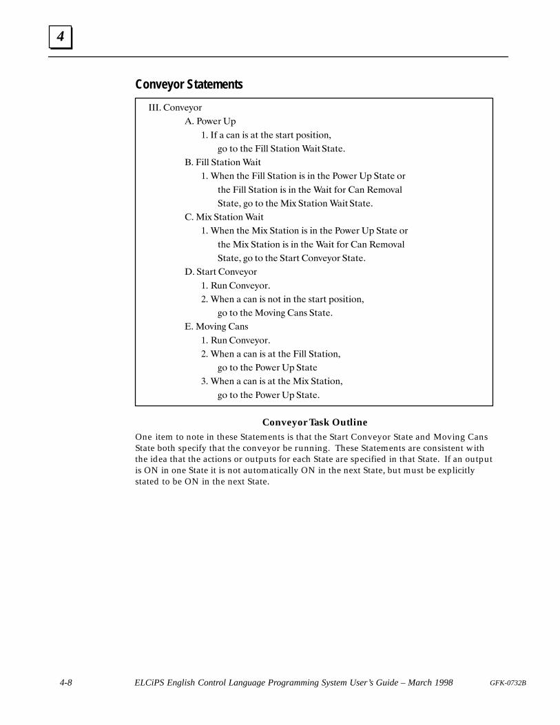
4
4-8 ELCiPS English Control Language Programming System User’s Guide – March 1998 GFK-0732B
Conveyor Statements
� ��$�'�
�� ��%� ��
�� � � ��� �! �" "�� !"� " ��!�"����
�� "� "�� ���� �"�"��� ���"�"�"��
�� ���� �"�"��� ���"
�� ���� "�� ���� �"�"��� �! �� "�� ��%� �� �"�"� �
"�� ���� �"�"��� �! �� "�� ���" �� �� ����$��
�"�"�� �� "� "�� ��& �"�"��� ���"�"�"��
� ��& �"�"��� ���"
�� ���� "�� ��& �"�"��� �! �� "�� ��%� �� �"�"� �
"�� ��& �"�"��� �! �� "�� ���" �� �� ����$��
�"�"�� �� "� "�� �"� " ��$�'� �"�"��
� �"� " ��$�'�
�� �#� ��$�'� �
�� ���� � ��� �! ��" �� "�� !"� " ��!�"����
�� "� "�� ��$��� ��! �"�"��
�� ��$��� ��!
�� �#� ��$�'� �
�� ���� � ��� �! �" "�� ���� �"�"����
�� "� "�� ��%� �� �"�"�
�� ���� � ��� �! �" "�� ��& �"�"����
�� "� "�� ��%� �� �"�"��
Conveyor Task OutlineOne item to note in these Statements is that the Start Conveyor State and Moving CansState both specify that the conveyor be running. These Statements are consistent withthe idea that the actions or outputs for each State are specified in that State. If an outputis ON in one State it is not automatically ON in the next State, but must be explicitlystated to be ON in the next State.

4
4-9GFK-0732B Chapter 4 Programming Tutorial
Writing the Program
This section demonstrates writing the ECLiPS control program from an outline of thecontrol application. First the I/O for the application are defined on paper, then the actualentry of the control process is described keystroke by keystroke.
Identify the I/O
The outline has been written in general terms describing the activities of the application.To write the actual program real world outputs and inputs must be specified. The actualassignment of names to input and output circuits may be done before, during, or afterthe program is written. In this section the actual I/O devices and their program namesare specified.
The table in this section identifies the actual I/O devices for this application and thenames to be used in the program. See the Effective Use of English Names part of theCreating a Control Program chapter of this manual.
Clever, descriptive names that fit well to the primary attribute of that circuit’s function isstrongly encouraged. This practice pays dividends in future program modifying, cleardocumentation and easier troubleshooting.
Further, good descriptive names will enhance the quality of the automatic diagnosticsthat can be created by linking Task, State and I/O names together for automatic diagnos-tic output information.
Each name can have up to a twenty characters. Names can contain letters, numbers andthe underscore character (_) but must begin with a letter. The name must be a continu-ous string of characters.
Because ECLiPS uses the space character as a way to tell where one word ends and thenext begins, as we normally do in written English, a name can not contain a space. Toconstruct a multiple word name for descriptive purposes the designer should use theunderscore character (_) to separate words or use uppercase to start every new word.
����������������
��������������
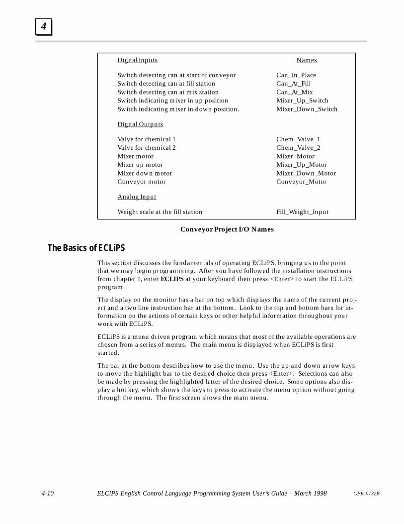
4
4-10 ELCiPS English Control Language Programming System User’s Guide – March 1998 GFK-0732B
Digital Inputs Names
Switch detecting can at start of conveyor Can_In_PlaceSwitch detecting can at fill station Can_At_FillSwitch detecting can at mix station Can_At_MixSwitch indicating mixer in up position Mixer_Up_SwitchSwitch indicating mixer in down position. Mixer_Down_Switch
Digital Outputs
Valve for chemical 1 Chem_Valve_1Valve for chemical 2 Chem_Valve_2Mixer motor Mixer_MotorMixer up motor Mixer_Up_MotorMixer down motor Mixer_Down_MotorConveyor motor Conveyor_Motor
Analog Input
Weight scale at the fill station Fill_Weight_Input
Conveyor Project I/O Names
The Basics of ECLiPS
This section discusses the fundamentals of operating ECLiPS, bringing us to the pointthat we may begin programming. After you have followed the installation instructionsfrom chapter 1, enter ECLIPS at your keyboard then press <Enter> to start the ECLiPSprogram.
The display on the monitor has a bar on top which displays the name of the current proj-ect and a two line instruction bar at the bottom. Look to the top and bottom bars for in-formation on the actions of certain keys or other helpful information throughout yourwork with ECLiPS.
ECLiPS is a menu driven program which means that most of the available operations arechosen from a series of menus. The main menu is displayed when ECLiPS is firststarted.
The bar at the bottom describes how to use the menu. Use the up and down arrow keysto move the highlight bar to the desired choice then press <Enter>. Selections can alsobe made by pressing the highlighted letter of the desired choice. Some options also dis-play a hot key, which shows the keys to press to activate the menu option without goingthrough the menu. The first screen shows the main menu.
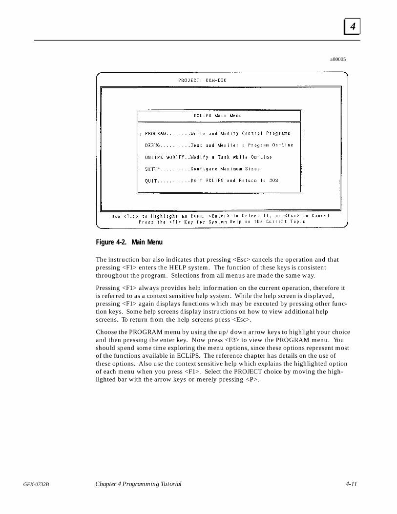
4
4-11GFK-0732B Chapter 4 Programming Tutorial
a80005
Figure 4-2. Main Menu
The instruction bar also indicates that pressing <Esc> cancels the operation and thatpressing <F1> enters the HELP system. The function of these keys is consistentthroughout the program. Selections from all menus are made the same way.
Pressing <F1> always provides help information on the current operation, therefore itis referred to as a context sensitive help system. While the help screen is displayed,pressing <F1> again displays functions which may be executed by pressing other func-tion keys. Some help screens display instructions on how to view additional helpscreens. To return from the help screens press <Esc>.
Choose the PROGRAM menu by using the up/down arrow keys to highlight your choiceand then pressing the enter key. Now press <F3> to view the PROGRAM menu. Youshould spend some time exploring the menu options, since these options represent mostof the functions available in ECLiPS. The reference chapter has details on the use ofthese options. Also use the context sensitive help which explains the highlighted optionof each menu when you press <F1>. Select the PROJECT choice by moving the high-lighted bar with the arrow keys or merely pressing <P>.
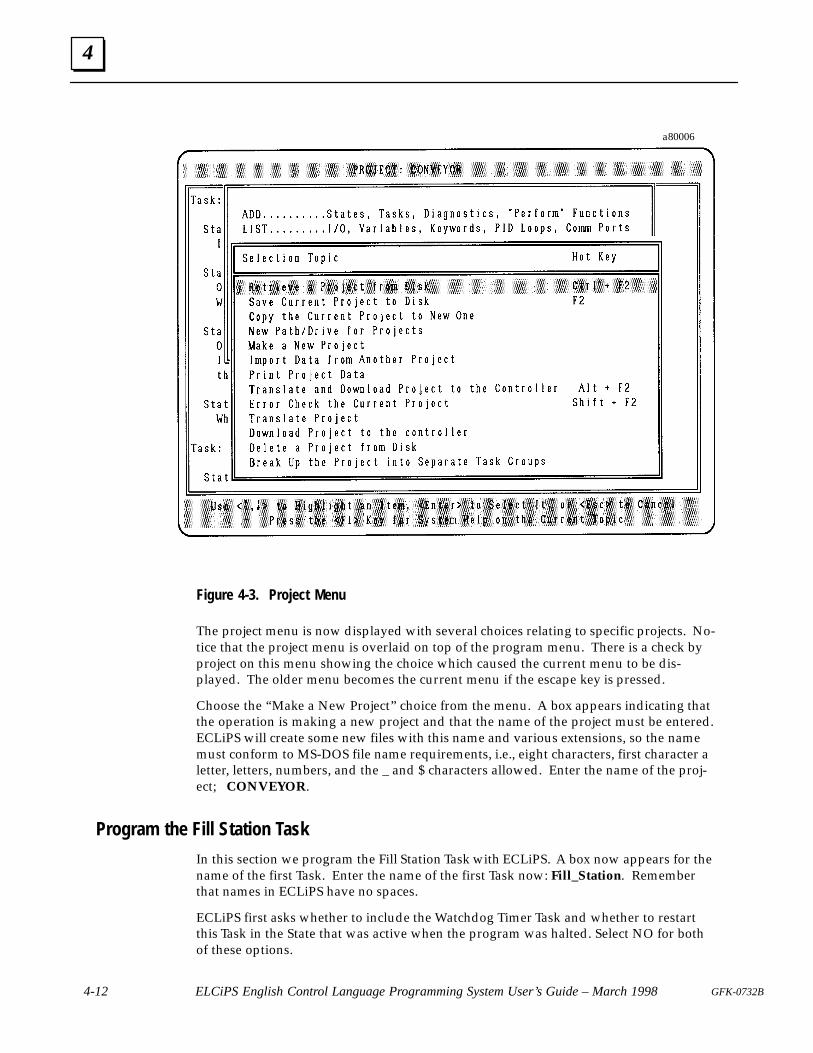
4
4-12 ELCiPS English Control Language Programming System User’s Guide – March 1998 GFK-0732B
a80006
Figure 4-3. Project Menu
The project menu is now displayed with several choices relating to specific projects. No-tice that the project menu is overlaid on top of the program menu. There is a check byproject on this menu showing the choice which caused the current menu to be dis-played. The older menu becomes the current menu if the escape key is pressed.
Choose the “Make a New Project” choice from the menu. A box appears indicating thatthe operation is making a new project and that the name of the project must be entered.ECLiPS will create some new files with this name and various extensions, so the namemust conform to MS-DOS file name requirements, i.e., eight characters, first character aletter, letters, numbers, and the _ and $ characters allowed. Enter the name of the proj-ect; CONVEYOR.
Program the Fill Station Task
In this section we program the Fill Station Task with ECLiPS. A box now appears for thename of the first Task. Enter the name of the first Task now: Fill_Station. Rememberthat names in ECLiPS have no spaces.
ECLiPS first asks whether to include the Watchdog Timer Task and whether to restartthis Task in the State that was active when the program was halted. Select NO for bothof these options.
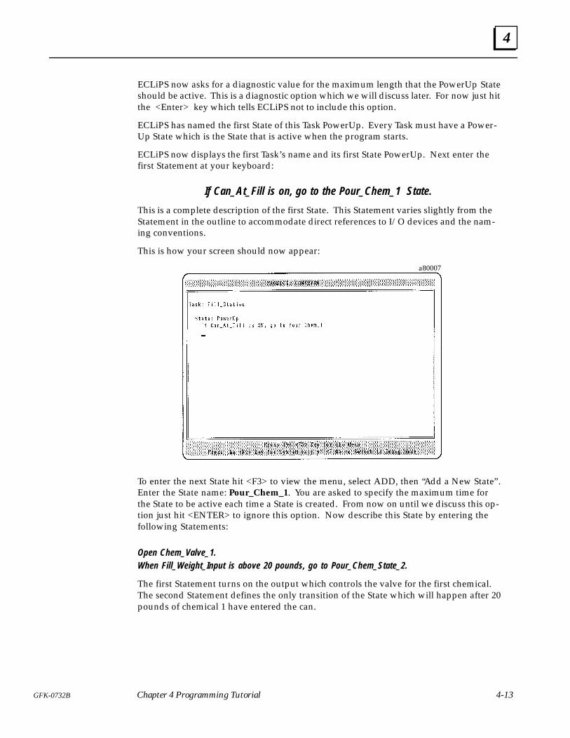
4
4-13GFK-0732B Chapter 4 Programming Tutorial
ECLiPS now asks for a diagnostic value for the maximum length that the PowerUp Stateshould be active. This is a diagnostic option which we will discuss later. For now just hitthe <Enter> key which tells ECLiPS not to include this option.
ECLiPS has named the first State of this Task PowerUp. Every Task must have a Power-Up State which is the State that is active when the program starts.
ECLiPS now displays the first Task’s name and its first State PowerUp. Next enter thefirst Statement at your keyboard:
If Can_At_Fill is on, go to the Pour_Chem_1 State.
This is a complete description of the first State. This Statement varies slightly from theStatement in the outline to accommodate direct references to I/O devices and the nam-ing conventions.
This is how your screen should now appear:
a80007
To enter the next State hit <F3> to view the menu, select ADD, then “Add a New State” .Enter the State name: Pour_Chem_1. You are asked to specify the maximum time forthe State to be active each time a State is created. From now on until we discuss this op-tion just hit <ENTER> to ignore this option. Now describe this State by entering thefollowing Statements:
Open Chem_Valve_1.When Fill_Weight_Input is above 20 pounds, go to Pour_Chem_State_2.
The first Statement turns on the output which controls the valve for the first chemical.The second Statement defines the only transition of the State which will happen after 20pounds of chemical 1 have entered the can.
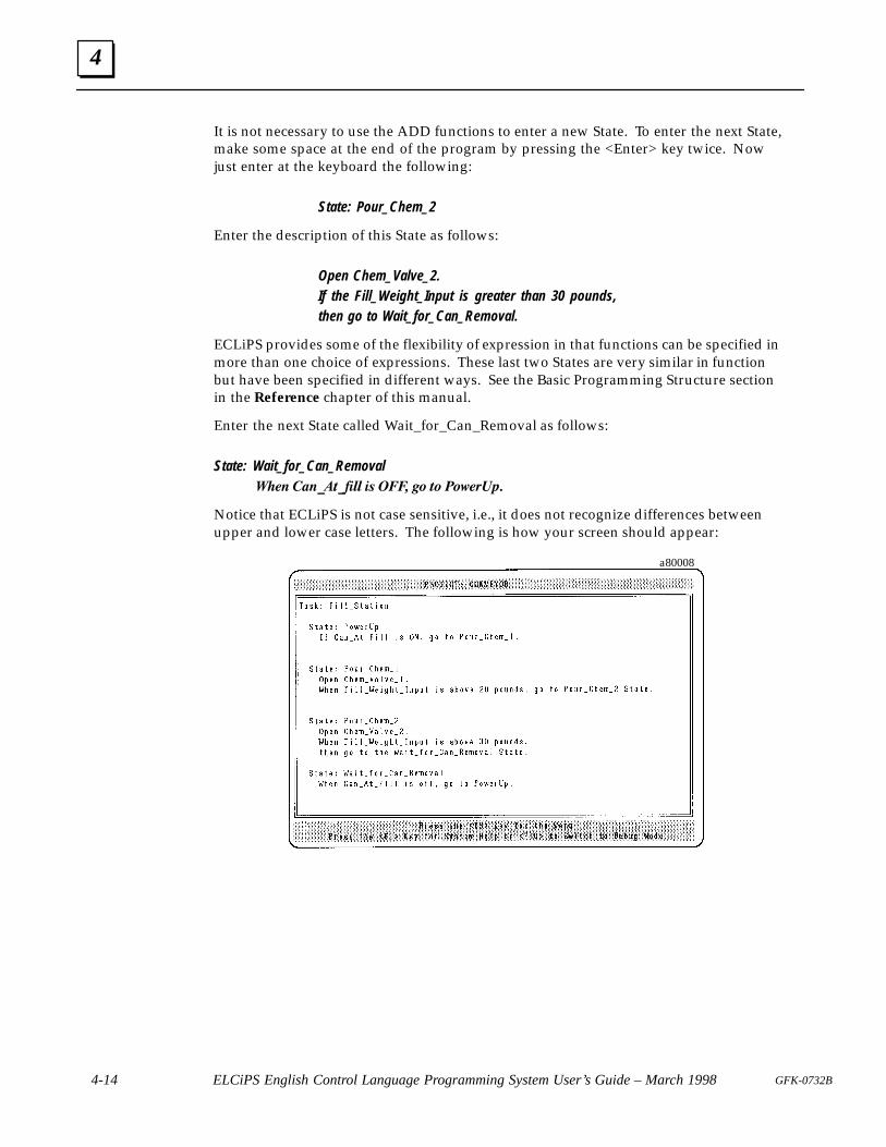
4
4-14 ELCiPS English Control Language Programming System User’s Guide – March 1998 GFK-0732B
It is not necessary to use the ADD functions to enter a new State. To enter the next State,make some space at the end of the program by pressing the <Enter> key twice. Nowjust enter at the keyboard the following:
State: Pour_Chem_2
Enter the description of this State as follows:
Open Chem_Valve_2.If the Fill_Weight_Input is greater than 30 pounds,then go to Wait_for_Can_Removal.
ECLiPS provides some of the flexibility of expression in that functions can be specified inmore than one choice of expressions. These last two States are very similar in functionbut have been specified in different ways. See the Basic Programming Structure sectionin the Reference chapter of this manual.
Enter the next State called Wait_for_Can_Removal as follows:
State: Wait_for_Can_Removal � � ����������� �� ���� �� �� ��� ���
Notice that ECLiPS is not case sensitive, i.e., it does not recognize differences betweenupper and lower case letters. The following is how your screen should appear:
a80008
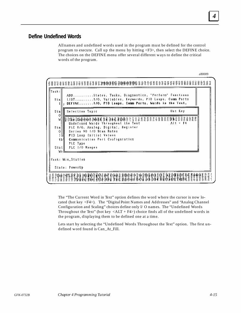
4
4-15GFK-0732B Chapter 4 Programming Tutorial
Define Undefined Words
All names and undefined words used in the program must be defined for the controlprogram to execute. Call up the menu by hitting <F3>, then select the DEFINE choice.The choices on the DEFINE menu offer several different ways to define the criticalwords of the program.
a80009
The “The Current Word in Text” option defines the word where the cursor is now lo-cated (hot key <F4>). The “Digital Point Names and Addresses” and “Analog ChannelConfiguration and Scaling” choices define only I/O names. The “Undefined WordsThroughout the Text” (hot key <ALT + F4>) choice finds all of the undefined words inthe program, displaying them to be defined one at a time.
Lets start by selecting the “Undefined Words Throughout the Text” option. The first un-defined word found is Can_At_Fill.
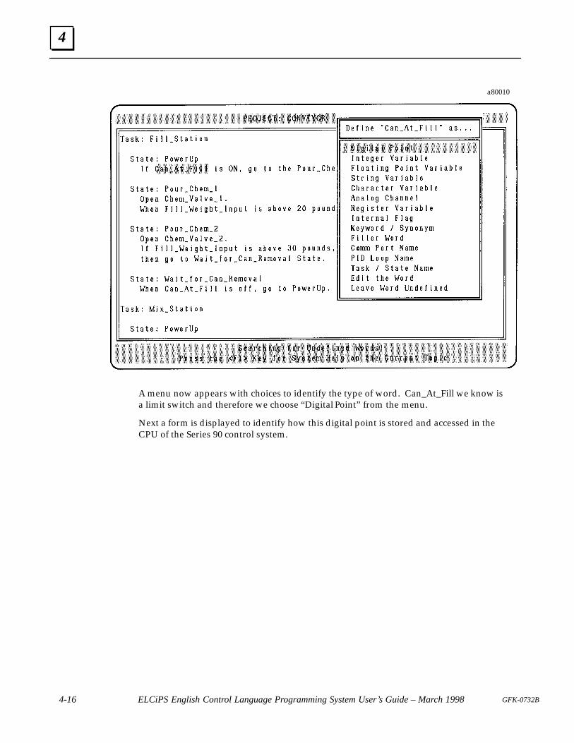
4
4-16 ELCiPS English Control Language Programming System User’s Guide – March 1998 GFK-0732B
a80010
A menu now appears with choices to identify the type of word. Can_At_Fill we know isa limit switch and therefore we choose “Digital Point” from the menu.
Next a form is displayed to identify how this digital point is stored and accessed in theCPU of the Series 90 control system.
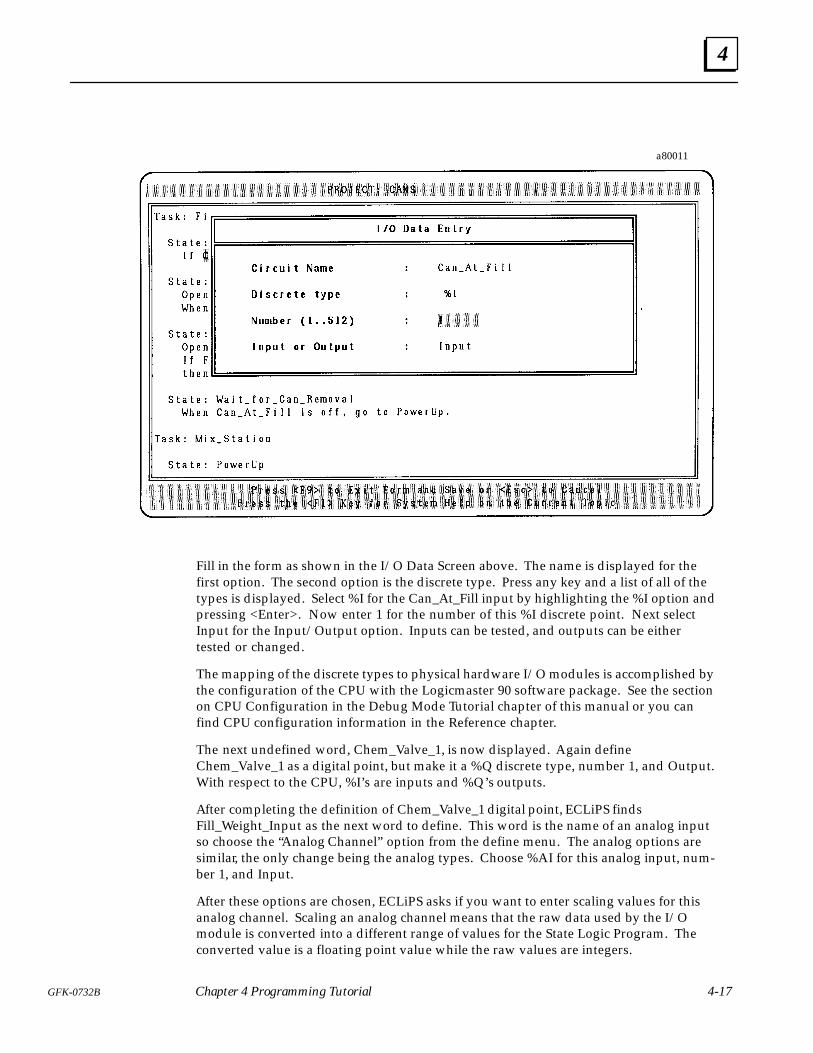
4
4-17GFK-0732B Chapter 4 Programming Tutorial
a80011
Fill in the form as shown in the I/O Data Screen above. The name is displayed for thefirst option. The second option is the discrete type. Press any key and a list of all of thetypes is displayed. Select %I for the Can_At_Fill input by highlighting the %I option andpressing <Enter>. Now enter 1 for the number of this %I discrete point. Next selectInput for the Input/Output option. Inputs can be tested, and outputs can be eithertested or changed.
The mapping of the discrete types to physical hardware I/O modules is accomplished bythe configuration of the CPU with the Logicmaster 90 software package. See the sectionon CPU Configuration in the Debug Mode Tutorial chapter of this manual or you canfind CPU configuration information in the Reference chapter.
The next undefined word, Chem_Valve_1, is now displayed. Again defineChem_Valve_1 as a digital point, but make it a %Q discrete type, number 1, and Output.With respect to the CPU, %I’s are inputs and %Q’s outputs.
After completing the definition of Chem_Valve_1 digital point, ECLiPS findsFill_Weight_Input as the next word to define. This word is the name of an analog inputso choose the “Analog Channel” option from the define menu. The analog options aresimilar, the only change being the analog types. Choose %AI for this analog input, num-ber 1, and Input.
After these options are chosen, ECLiPS asks if you want to enter scaling values for thisanalog channel. Scaling an analog channel means that the raw data used by the I/Omodule is converted into a different range of values for the State Logic Program. Theconverted value is a floating point value while the raw values are integers.
4
4-18 ELCiPS English Control Language Programming System User’s Guide – March 1998 GFK-0732B
Select the YES option to scale the Fill_Weight_Input analog channel. A form is displayedto specify how raw analog values (D/A or A/D) are converted to engineering units. Therange of raw values is selected during the configuration of the CPU using Logicmaster90.
Assuming that the analog channel configuration is 0 - 4095, fill in the A/D or D/A valuesin the form as 0 for the Low Point and 4095 for the high point. The Fill_Weight_Inputrepresents a scale which measures from 0 to 50 pounds. Enter 0 for the Low Point engi-neering units value and 50 for the High value. All references to this analog input in theprogram, return a floating point value from 0 to 50.
Chem_Valve_2 is the next undefined word, which must be defined as a digital output.The next word to define is pounds. The definition of this word demonstrates how engi-neering units are handled in ECLiPS. The analog circuit configuration is set up so thatthe value returned represents the units desired. The units specified in the ECLiPS pro-gram serves documentation purposes, but has no effect on the operation of the controlprogram. Define this word as a filler word by choosing the Filler Word option from thedefine menu.
This concludes the programming of a complete State Logic Task. Notice that this Task byitself could be a completely independent program, if the Fill Station were the only partof the application to control. Take some time to explore the menus which offer some ofthe ECLiPS convenience features. The next chapter describes how to check the programand make changes.
Checking Your Work and Making ChangesAt this point all words have been defined, but there may be errors in the program andmost often changes need to be made throughout the life of a program. This sections dis-cusses checking the program for errors and how to make program changes.
To check the project for errors choose PROJECT from the menu, and then the “ErrorCheck the Current Project” option from the next menu (hot key <Shift + F2>). ECLiPSmay ask if you want to check for undefined words. Answer NO to this option. IfECLiPS finds no errors, a form is displayed showing the statistics on the current project.If there is an error, an error message is displayed in the bottom bar of the screen. Todemonstrate how errors are displayed, delete the period following the last Statement ofthe program. Now check the project for errors. When the error message is displayed,press the <CTRL + F1> to view the help message for this error.
To view definitions of the words for the project or to view other system attributes choosethe LIST option from the menu. A list of topics to view appears. Choose from the list oftopics to view the specific word definitions. The bar at the bottom of the screen showsseveral functions available to manipulate or use these definitions. The functions avail-able are inserting a new definition, deleting a definition, and editing the definition. Inaddition the word defined may be entered into the program at the current cursor loca-tion. The LIST option is very useful with large applications, since it is difficult to remem-ber all of the words that have been defined.
To make changes in the text of the program, ECLiPS provides the basic functions of aword processor. To move through the text use the arrow keys, <HOME> and <END>keys, and <PAGE UP> and <PAGE DOWN> keys. Use the backspace and delete keysto erase text, the enter key to add new lines, <ALT + F1> to toggle between insert modeand overtype mode, and the tab key to indent. To perform more advanced text editingoperations, use the FIND and TEXT options from the menu. Press the <F1> key twice
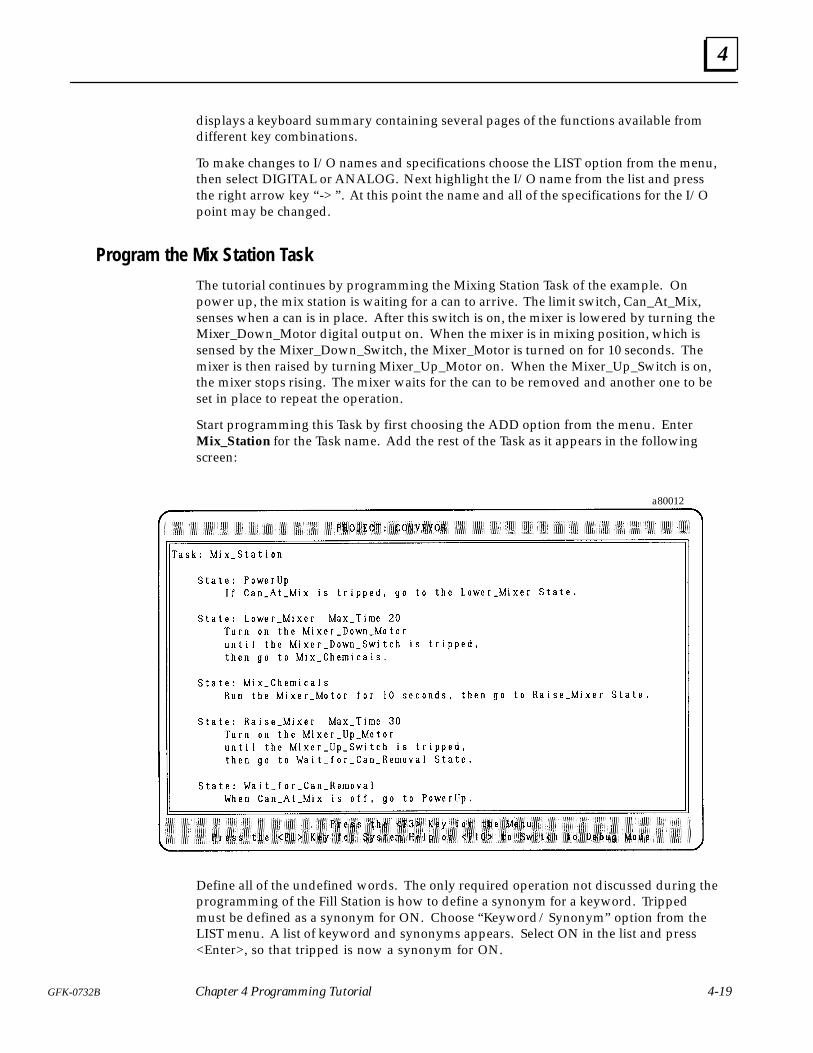
4
4-19GFK-0732B Chapter 4 Programming Tutorial
displays a keyboard summary containing several pages of the functions available fromdifferent key combinations.
To make changes to I/O names and specifications choose the LIST option from the menu,then select DIGITAL or ANALOG. Next highlight the I/O name from the list and pressthe right arrow key “ -> ” . At this point the name and all of the specifications for the I/Opoint may be changed.
Program the Mix Station Task
The tutorial continues by programming the Mixing Station Task of the example. Onpower up, the mix station is waiting for a can to arrive. The limit switch, Can_At_Mix,senses when a can is in place. After this switch is on, the mixer is lowered by turning theMixer_Down_Motor digital output on. When the mixer is in mixing position, which issensed by the Mixer_Down_Switch, the Mixer_Motor is turned on for 10 seconds. Themixer is then raised by turning Mixer_Up_Motor on. When the Mixer_Up_Switch is on,the mixer stops rising. The mixer waits for the can to be removed and another one to beset in place to repeat the operation.
Start programming this Task by first choosing the ADD option from the menu. EnterMix_Station for the Task name. Add the rest of the Task as it appears in the followingscreen:
a80012
Define all of the undefined words. The only required operation not discussed during theprogramming of the Fill Station is how to define a synonym for a keyword. Trippedmust be defined as a synonym for ON. Choose “Keyword / Synonym” option from theLIST menu. A list of keyword and synonyms appears. Select ON in the list and press<Enter>, so that tripped is now a synonym for ON.
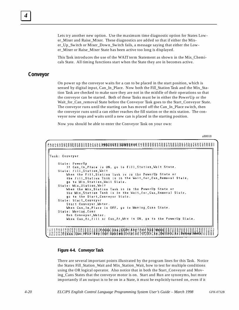
4
4-20 ELCiPS English Control Language Programming System User’s Guide – March 1998 GFK-0732B
Lets try another new option. Use the maximum time diagnostic option for States Low-er_Mixer and Raise_Mixer. These diagnostics are added so that if either the Mix-er_Up_Switch or Mixer_Down_Switch fails, a message saying that either the Low-er_Mixer or Raise_Mixer State has been active too long is displayed.
This Task introduces the use of the WAIT term Statement as shown in the Mix_Chemi-cals State. All timing functions start when the State they are in becomes active.
Conveyor
On power up the conveyor waits for a can to be placed in the start position, which issensed by digital input, Can_In_Place. Now both the Fill_Station Task and the Mix_Sta-tion Task are checked to make sure they are not in the middle of their operations so thatthe conveyor can be started. Both of these Tasks must be in either the PowerUp or theWait_for_Can_removal State before the Conveyor Task goes to the Start_Conveyor State.The conveyor runs until the starting can has moved off the Can_In_Place switch, thenthe conveyor runs until a can either reaches the fill station or the mix station. The con-veyor now stops and waits until a new can is placed in the starting position.
Now you should be able to enter the Conveyor Task on your own:
a80018
Figure 4-4. Conveyor Task
There are several important points illustrated by the program lines for this Task. Noticethe States Fill_Station_Wait and Mix_Station_Wait, how to test for multiple conditionsusing the OR logical operator. Also notice that in both the Start_Conveyor and Mov-ing_Cans States that the conveyor motor is on. Start and Run are synonyms, but moreimportantly if an output is to be on in a State, it must be explicitly turned on, even if it
4
4-21GFK-0732B Chapter 4 Programming Tutorial
were on in the previous State. The inputs Can_At_Fill and Can_At_Mix are used in theother Tasks and can also be used in this Task.
The State Engine scans the active States of each Task one Statement at a time. If a com-mand to transition to another State is scanned, the remaining Statements are notscanned. The final two Statements of Moving_Cans State demonstrate these scanningcharacteristics, since if the first conditional is true, the next Statement is not scanned.
Check the program again for errors. Correct any problems found. Now save the pro-gram by choosing PROJECT from the menu and then the “Save Current Project to Disk”option.
Congratulations! You have just programmed an application using State Logic.
Advanced Programming Terms and Diagnostics
The program developed so far demonstrates the basics of the State Logic Control theory.This program is now changed to demonstrate how to send messages to a terminal, readinformation from a keyboard, add some diagnostics, and program a counter.
Read and Write TermsAssume that after the program has been operating for awhile, a decision is made to usetwo different types of cans, types A and B. The operator enters the type of can after it isplaced onto the conveyor. A message is sent to the screen prompting the operator toenter the type of can placed on the conveyor.
�&�&�� �"(�$�#
�� &�� ��!��!�� ��� �% "!�
($�&� “ �!&�$ &)#� "� ��! � "$ �� &��! ��������” �!�
�" &" &�� �#�$�&"$��!#'& �&�&��
�&�&���#�$�&"$��!#'&
���� ��!��)#�� &��! �" &" &�� � ��&�&�"!����& �&�&��
Enter the program changes as shown above. First the PowerUp State of the ConveyorTask is changed so that a message is sent to the screen after the Can_In_Place switch istripped. A new State is added which reads the operator’s entry at the keyboard. ThisState is called Operator_Input and becomes active after the Can_In_Place switch is ON.As soon as this input is entered at the keyboard, the State transitions to theReady_To_Move State and the conveyor Task continues execution as before.
When adding States to a program, make sure the cursor is at the position where the newState is to appear before selecting the ADD option from the menu or merely type in theprogram changes as they appear above.
Define Can_Type to be a string variable. The write term is a functional term which mustappear after the conditional term in the Statement. The write term sends everythingthat appears inside the double quote marks to the terminal, therefore the period is sentto the terminal as part of the message transmitted and does not indicate the end of theStatement.
The read term is a conditional term which is not satisfied or true until the <Enter> keyis pressed signaling the end of the operator input. Therefore the read term must be used
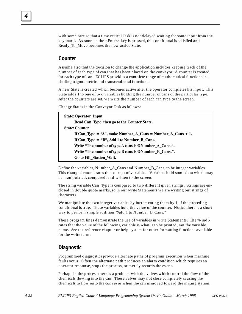
4
4-22 ELCiPS English Control Language Programming System User’s Guide – March 1998 GFK-0732B
with some care so that a time critical Task is not delayed waiting for some input from thekeyboard. As soon as the <Enter> key is pressed, the conditional is satisfied andReady_To_Move becomes the new active State.
CounterAssume also that the decision to change the application includes keeping track of thenumber of each type of can that has been placed on the conveyor. A counter is createdfor each type of can. ECLiPS provides a complete range of mathematical functions in-cluding trigonometric and transcendental functions.
A new State is created which becomes active after the operator completes his input. ThisState adds 1 to one of two variables holding the number of cans of the particular type.After the counters are set, we write the number of each can type to the screen.
Change States in the Conveyor Task as follows:
�'�'���$�%�'#%��"$('
���� ��"��)$�� '��" �# '# '�� �#("'�% �'�'��
�'�'�� �#("'�%
�� ��"��)$� � “” � !��� �(!��%����"& � �(!��%����"& � ��
�� ��"��)$� � “ ” � �� � '# �(!��%����"&�
�%�'� “ ��� "(!��% #� ')$� ��"& �& ��(!��%����"&�” �
�%�'� “ ��� "(!��% #� ')$� ��"& �& ��(!��%����"&�” �
# '# �� ��'�'�#"����'�
Define the variables, Number_A_Cans and Number_B_Cans, to be integer variables.This change demonstrates the concept of variables. Variables hold some data which maybe manipulated, compared, and written to the screen.
The string variable Can_Type is compared to two different given strings. Strings are en-closed in double quote marks, so in our write Statements we are writing out strings ofcharacters.
We manipulate the two integer variables by incrementing them by 1, if the precedingconditional is true. These variables hold the value of the counter. Notice there is a shortway to perform simple addition: “Add 1 to Number_B_Cans.”
These program lines demonstrate the use of variables in write Statements. The % indi-cates that the value of the following variable is what is to be printed, not the variablename. See the reference chapter or help system for other formatting functions availablefor the write term.
DiagnosticProgrammed diagnostics provide alternate paths of program execution when machinefaults occur. Often the alternate path produces an alarm condition which requires anoperator response, stops the process, or merely records the event.
Perhaps in the process there is a problem with the valves which control the flow of thechemicals flowing into the can. These valves may not close completely causing thechemicals to flow onto the conveyor when the can is moved toward the mixing station.
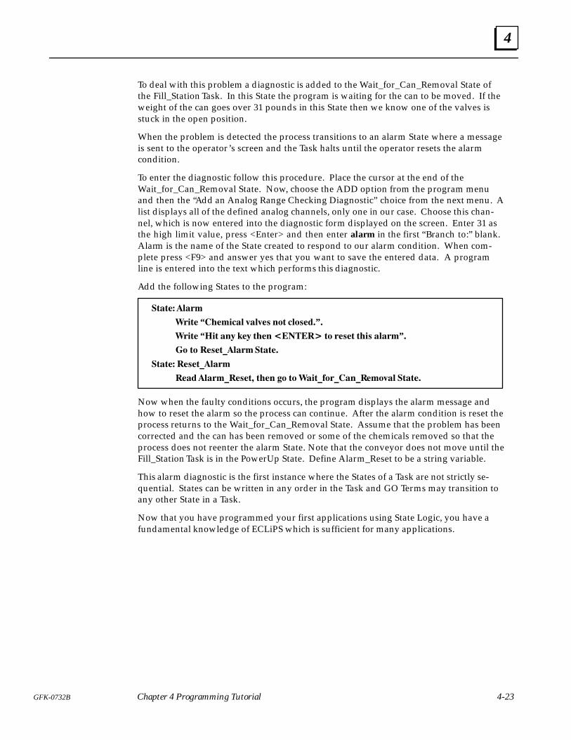
4
4-23GFK-0732B Chapter 4 Programming Tutorial
To deal with this problem a diagnostic is added to the Wait_for_Can_Removal State ofthe Fill_Station Task. In this State the program is waiting for the can to be moved. If theweight of the can goes over 31 pounds in this State then we know one of the valves isstuck in the open position.
When the problem is detected the process transitions to an alarm State where a messageis sent to the operator’s screen and the Task halts until the operator resets the alarmcondition.
To enter the diagnostic follow this procedure. Place the cursor at the end of theWait_for_Can_Removal State. Now, choose the ADD option from the program menuand then the “Add an Analog Range Checking Diagnostic” choice from the next menu. Alist displays all of the defined analog channels, only one in our case. Choose this chan-nel, which is now entered into the diagnostic form displayed on the screen. Enter 31 asthe high limit value, press <Enter> and then enter alarm in the first “Branch to:” blank.Alarm is the name of the State created to respond to our alarm condition. When com-plete press <F9> and answer yes that you want to save the entered data. A programline is entered into the text which performs this diagnostic.
Add the following States to the program:
�!�!�� �����
���!� “�������� "��"� ��! ��� ���” �
���!� “��! ��# ��# !��� ��� � !� �� �! !�� �����” �
� !� � �!�������!�!��
�!�!�� � �!������
��� ������ � �!� !��� �� !� ���!��������� ���"�� �!�!��
Now when the faulty conditions occurs, the program displays the alarm message andhow to reset the alarm so the process can continue. After the alarm condition is reset theprocess returns to the Wait_for_Can_Removal State. Assume that the problem has beencorrected and the can has been removed or some of the chemicals removed so that theprocess does not reenter the alarm State. Note that the conveyor does not move until theFill_Station Task is in the PowerUp State. Define Alarm_Reset to be a string variable.
This alarm diagnostic is the first instance where the States of a Task are not strictly se-quential. States can be written in any order in the Task and GO Terms may transition toany other State in a Task.
Now that you have programmed your first applications using State Logic, you have afundamental knowledge of ECLiPS which is sufficient for many applications.
5 section level 1 1figure bi level 1 table_big level 1
5-1GFK-0732B
Chapter 5 Helpful Hints
The hints and suggestions found in this chapter have been developed by ECLiPS andState Language programmers in an effort to make the user’s first programming experi-ence as productive as possible. There are two parts to this chapter, one giving hints forprogramming and the other has suggestions for using the tools provided as part ofECLiPS.
Programming Hints
Outputs are OFF by Default
One of the key features a of the State Logic model is that the discrete outputs are OFF bydefault (their normal condition). Outputs are only ON if they are being turned ON by aprogram Statement in an active State.
This arrangement enables the State Logic model to have a one-to-one correspondencebetween the control program and the real world. States in the program exactly reflectthe States of the machine being controlled. There are other direct benefits of the outputsbeing OFF by default.
While writing the State Logic program, the programmer need not be concerned withturning any outputs OFF. Having to be concerned with turning outputs OFF adds muchcomplexity not to mention a great deal of logic to a control program.
Another feature of this arrangement appears when troubleshooting or debugging anexecuting program. To see which outputs are ON at any point in time, one only needcheck the State definitions of the active States of each Task. Any outputs set ON in theseStates are ON and all others are OFF.
Outputs are turned on by using the keyword Start (or any of the synonyms such asTurn_On, Energize, Actuate, etc.). Outputs are turned off when another State that doesNOT turn on the output becomes active. An example is listed below:
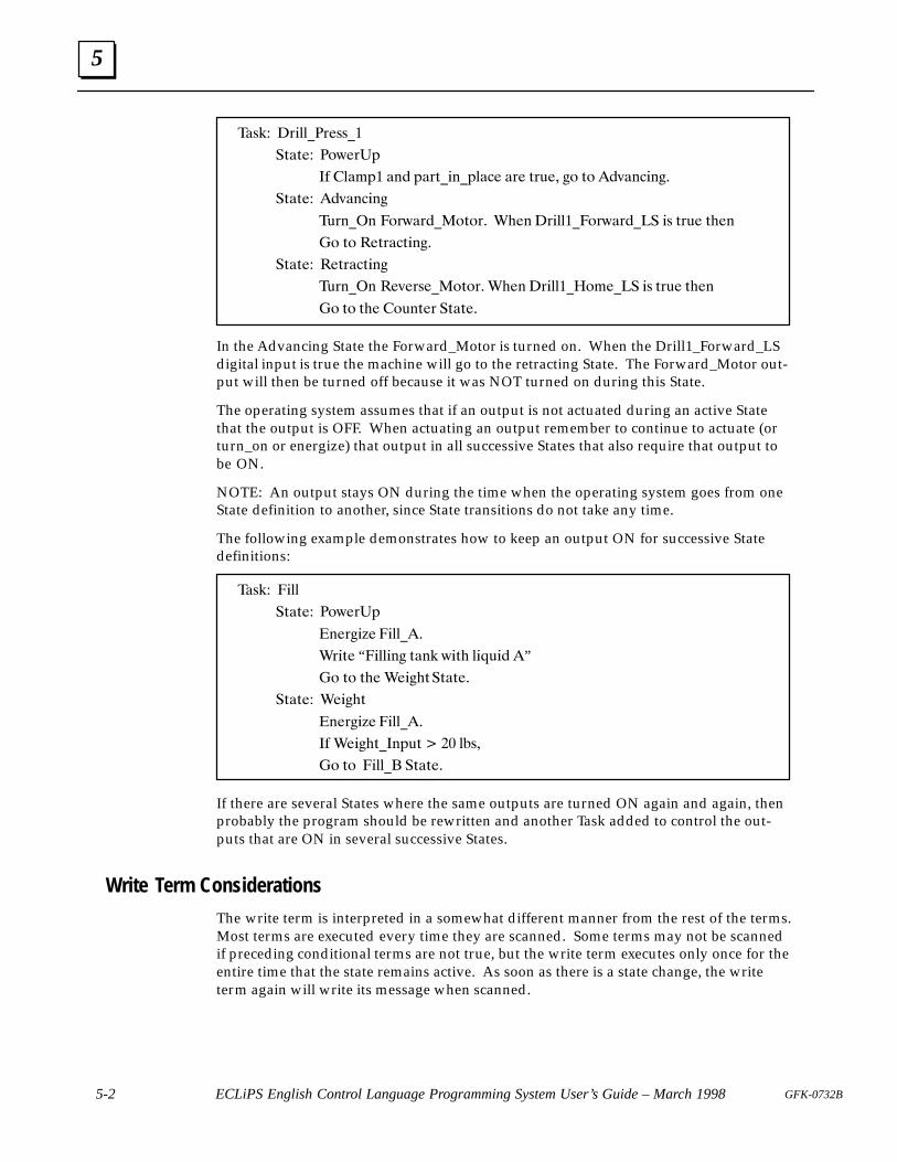
5
5-2 ECLiPS English Control Language Programming System User’s Guide – March 1998 GFK-0732B
��-%� �,$&&��, --��
�.�. � �)1 ,�*
�! �&�'*� �(� *�,.�$(�*&�� �, .,/ � ") .) �0�(�$("�
�.�. � �0�(�$("
�/,(��( �),1�,���).),� �# ( �,$&&���),1�,���� $- .,/ .# (
�) .) � .,��.$("�
�.�. � � .,��.$("
�/,(��( � 0 ,- ��).),� �# ( �,$&&���)' ��� $- .,/ .# (
�) .) .# �)/(. , �.�. �
In the Advancing State the Forward_Motor is turned on. When the Drill1_Forward_LSdigital input is true the machine will go to the retracting State. The Forward_Motor out-put will then be turned off because it was NOT turned on during this State.
The operating system assumes that if an output is not actuated during an active Statethat the output is OFF. When actuating an output remember to continue to actuate (orturn_on or energize) that output in all successive States that also require that output tobe ON.
NOTE: An output stays ON during the time when the operating system goes from oneState definition to another, since State transitions do not take any time.
The following example demonstrates how to keep an output ON for successive Statedefinitions:
��-%� �$&&
�.�. � �)1 ,�*
( ,"$2 �$&&��
�,$. “�$&&$(" .�(% 1$.# &$+/$� ”
�) .) .# � $"#.�.�. �
�.�. � � $"#.
( ,"$2 �$&&��
�! � $"#.��(*/. � �� &�-�
�) .) �$&&� �.�. �
If there are several States where the same outputs are turned ON again and again, thenprobably the program should be rewritten and another Task added to control the out-puts that are ON in several successive States.
Write Term Considerations
The write term is interpreted in a somewhat different manner from the rest of the terms.Most terms are executed every time they are scanned. Some terms may not be scannedif preceding conditional terms are not true, but the write term executes only once for theentire time that the state remains active. As soon as there is a state change, the writeterm again will write its message when scanned.
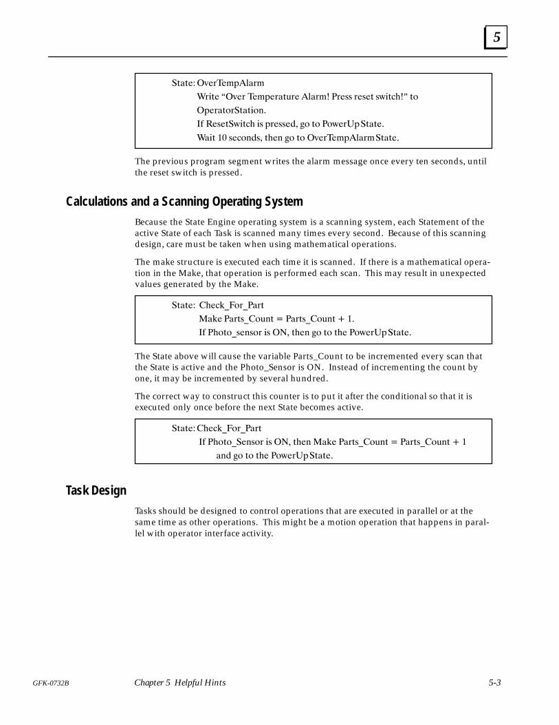
5
5-3GFK-0732B Chapter 5 Helpful Hints
�(�(���*�&��"%!�&"
�&�(� “�*�& ��"%�&�()&� !�&"� �&�'' &�'�( '+�(���” ($
�%�&�($&�(�(�$#�
� ��'�(�+�(�� �' %&�''��� �$ ($ �$+�&�%�(�(��
���( �� '��$#�'� (��# �$ ($ �*�&��"%!�&"�(�(��
The previous program segment writes the alarm message once every ten seconds, untilthe reset switch is pressed.
Calculations and a Scanning Operating System
Because the State Engine operating system is a scanning system, each Statement of theactive State of each Task is scanned many times every second. Because of this scanningdesign, care must be taken when using mathematical operations.
The make structure is executed each time it is scanned. If there is a mathematical opera-tion in the Make, that operation is performed each scan. This may result in unexpectedvalues generated by the Make.
�(�(�� ���� ��$&���&(
�� � ��&('��$)#( ��&('��$)#( � ��
� ��$($�'�#'$& �' ��� (��# �$ ($ (�� �$+�&�%�(�(��
The State above will cause the variable Parts_Count to be incremented every scan thatthe State is active and the Photo_Sensor is ON. Instead of incrementing the count byone, it may be incremented by several hundred.
The correct way to construct this counter is to put it after the conditional so that it isexecuted only once before the next State becomes active.
�(�(������ ��$&���&(
� ��$($���#'$& �' ��� (��# �� � ��&('��$)#( ��&('��$)#( � �
�#� �$ ($ (�� �$+�&�%�(�(��
Task Design
Tasks should be designed to control operations that are executed in parallel or at thesame time as other operations. This might be a motion operation that happens in paral-lel with operator interface activity.
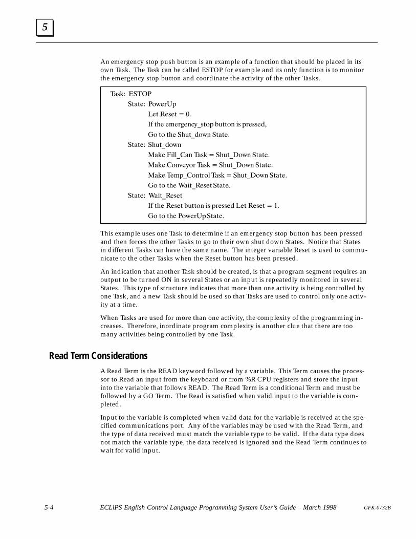
5
5-4 ECLiPS English Control Language Programming System User’s Guide – March 1998 GFK-0732B
An emergency stop push button is an example of a function that should be placed in itsown Task. The Task can be called ESTOP for example and its only function is to monitorthe emergency stop button and coordinate the activity of the other Tasks.
��(!� ����
�)�)�� �%,�'�&
��) ��(�) � ��
� )�� �#�'��$�-�()%& �*))%$ ( &'�((���
�% )% )�� ��*)��%,$ �)�)��
�)�)�� ��*)��%,$
��!� � ""���$ ��(! � ��*)�%,$ �)�)��
��!� �%$+�-%' ��(! � ��*)�%,$ �)�)��
��!� ��#&��%$)'%" ��(! � ��*)�%,$ �)�)��
�% )% )�� �� )���(�)�)�)��
�)�)�� �� )���(�)
� )�� ��(�) �*))%$ ( &'�((�� ��) ��(�) � ��
�% )% )�� �%,�'�&�)�)��
This example uses one Task to determine if an emergency stop button has been pressedand then forces the other Tasks to go to their own shut down States. Notice that Statesin different Tasks can have the same name. The integer variable Reset is used to commu-nicate to the other Tasks when the Reset button has been pressed.
An indication that another Task should be created, is that a program segment requires anoutput to be turned ON in several States or an input is repeatedly monitored in severalStates. This type of structure indicates that more than one activity is being controlled byone Task, and a new Task should be used so that Tasks are used to control only one activ-ity at a time.
When Tasks are used for more than one activity, the complexity of the programming in-creases. Therefore, inordinate program complexity is another clue that there are toomany activities being controlled by one Task.
Read Term Considerations
A Read Term is the READ keyword followed by a variable. This Term causes the proces-sor to Read an input from the keyboard or from %R CPU registers and store the inputinto the variable that follows READ. The Read Term is a conditional Term and must befollowed by a GO Term. The Read is satisfied when valid input to the variable is com-pleted.
Input to the variable is completed when valid data for the variable is received at the spe-cified communications port. Any of the variables may be used with the Read Term, andthe type of data received must match the variable type to be valid. If the data type doesnot match the variable type, the data received is ignored and the Read Term continues towait for valid input.
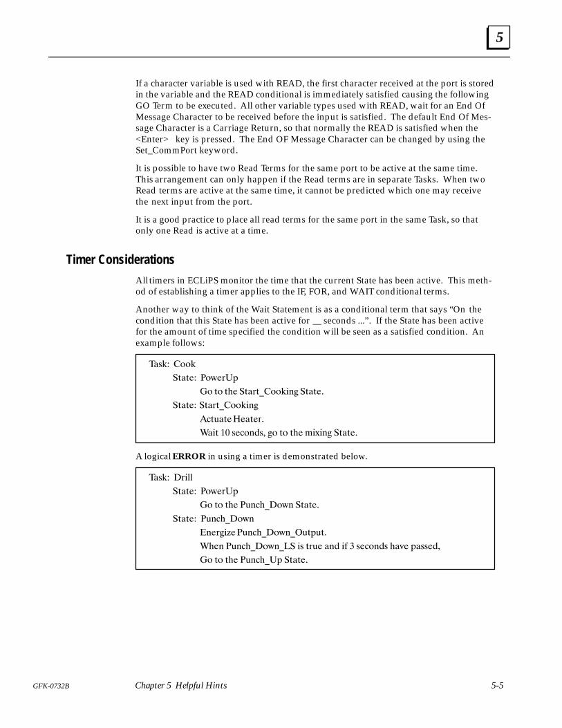
5
5-5GFK-0732B Chapter 5 Helpful Hints
If a character variable is used with READ, the first character received at the port is storedin the variable and the READ conditional is immediately satisfied causing the followingGO Term to be executed. All other variable types used with READ, wait for an End OfMessage Character to be received before the input is satisfied. The default End Of Mes-sage Character is a Carriage Return, so that normally the READ is satisfied when the<Enter> key is pressed. The End OF Message Character can be changed by using theSet_CommPort keyword.
It is possible to have two Read Terms for the same port to be active at the same time.This arrangement can only happen if the Read terms are in separate Tasks. When twoRead terms are active at the same time, it cannot be predicted which one may receivethe next input from the port.
It is a good practice to place all read terms for the same port in the same Task, so thatonly one Read is active at a time.
Timer Considerations
All timers in ECLiPS monitor the time that the current State has been active. This meth-od of establishing a timer applies to the IF, FOR, and WAIT conditional terms.
Another way to think of the Wait Statement is as a conditional term that says “On thecondition that this State has been active for seconds ...” . If the State has been activefor the amount of time specified the condition will be seen as a satisfied condition. Anexample follows:
��%�� ""�
�&�&�� �")�$�#
�" &" &�� �&�$&�""��!� �&�&��
�&�&�� �&�$&�""��!�
��&'�&� ��&�$�
���& �� %��"!�%� �" &" &�� �*�!� �&�&��
A logical ERROR in using a timer is demonstrated below.
��%�� $���
�&�&�� �")�$�#
�" &" &�� �'!���")! �&�&��
�&�&�� �'!���")!
�!�$��+��'!���")!��'&#'&�
���! �'!���")!��� �% &$'� �!� �� � %��"!�% ��(� #�%%���
�" &" &�� �'!����# �&�&��
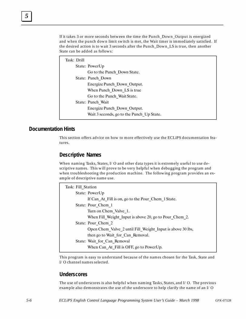
5
5-6 ECLiPS English Control Language Programming System User’s Guide – March 1998 GFK-0732B
If it takes 3 or more seconds between the time the Punch_Down_Output is energizedand when the punch down limit switch is met, the Wait timer is immediately satisfied. Ifthe desired action is to wait 3 seconds after the Punch_Down_LS is true, then anotherState can be added as follows:
��*#� �)"$$
�+�+�� �'.�)�(
�' +' +!� �,&�!��'.& �+�+��
�+�+�� �,&�!��'.&
�&�) "/��,&�!��'.&��,+(,+�
�!�& �,&�!��'.&��� "* +),�
�' +' +!� �,&�!���"+�+�+��
�+�+�� �,&�!���"+
�&�) "/��,&�!��'.&��,+(,+�
��"+ � *��'&�*� ' +' +!� �,&�!��( �+�+��
Documentation HintsThis section offers advice on how to more effectively use the ECLiPS documentation fea-tures.
Descriptive NamesWhen naming Tasks, States, I/O and other data types it is extremely useful to use de-scriptive names. This will prove to be very helpful when debugging the program andwhen troubleshooting the production machine. The following program provides an ex-ample of descriptive name use.
��*#� "$$��+�+"'&
�+�+�� �'.�)�(
�� �&�+� "$$ "* '&� ' +' +!� �',)�!�%���+�+��
�+�+�� �',)�!�%��
�,)& '& !�%���$-����
�!�& "$$���" !+��&(,+ "* ��'-� ��� ' +' �',)�!�%���
�+�+�� �',)�!�%��
�(�& !�%���$-��� ,&+"$ "$$���" !+��&(,+ "* ��'-� �� $�*�
+!�& ' +' ��"+��')��&���%'-�$�
�+�+�� ��"+��')��&���%'-�$
�!�& �&�+� "$$ "* � � ' +' �'.�)�(�
This program is easy to understand because of the names chosen for the Task, State andI/O channel names selected.
UnderscoresThe use of underscores is also helpful when naming Tasks, States, and I/O. The previousexample also demonstrates the use of the underscore to help clarify the name of an I/O
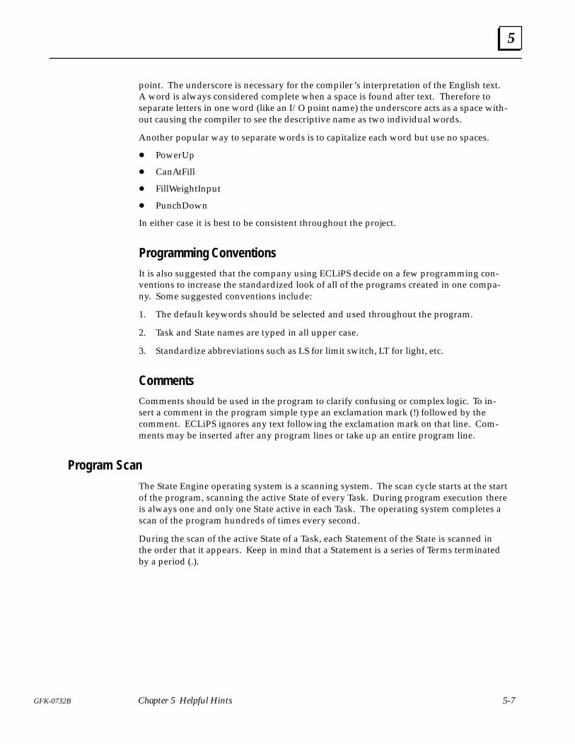
5
5-7GFK-0732B Chapter 5 Helpful Hints
point. The underscore is necessary for the compiler’s interpretation of the English text.A word is always considered complete when a space is found after text. Therefore toseparate letters in one word (like an I/O point name) the underscore acts as a space with-out causing the compiler to see the descriptive name as two individual words.
Another popular way to separate words is to capitalize each word but use no spaces.
� PowerUp
� CanAtFill
� FillWeightInput
� PunchDown
In either case it is best to be consistent throughout the project.
Programming ConventionsIt is also suggested that the company using ECLiPS decide on a few programming con-ventions to increase the standardized look of all of the programs created in one compa-ny. Some suggested conventions include:
1. The default keywords should be selected and used throughout the program.
2. Task and State names are typed in all upper case.
3. Standardize abbreviations such as LS for limit switch, LT for light, etc.
CommentsComments should be used in the program to clarify confusing or complex logic. To in-sert a comment in the program simple type an exclamation mark (!) followed by thecomment. ECLiPS ignores any text following the exclamation mark on that line. Com-ments may be inserted after any program lines or take up an entire program line.
Program Scan
The State Engine operating system is a scanning system. The scan cycle starts at the startof the program, scanning the active State of every Task. During program execution thereis always one and only one State active in each Task. The operating system completes ascan of the program hundreds of times every second.
During the scan of the active State of a Task, each Statement of the State is scanned inthe order that it appears. Keep in mind that a Statement is a series of Terms terminatedby a period (.).

5
5-8 ECLiPS English Control Language Programming System User’s Guide – March 1998 GFK-0732B
a80002
Figure 5-1. Program Scan
The actions specified by Functional Terms are executed when the Term is scanned. EachStatement must have at least one Functional Term, Conditional Terms are optional. Ifthere are no Conditional Terms in a Statement, the Functional Terms are always executedduring each scan. When Conditional Terms accompany Functional Terms in a Statement,the Functional Term is executed when all of the Conditional Terms are satisfied. Thereare four types of conditional Terms (see the reference chapter).
Conditional Terms are satisfied as follows:
1. Read - When valid data is received at the appropriate channel.
2. If - When the conditional expression is TRUE.
To understand how Statements are scanned, assume that the Statement ConditionalTerms precede the Functional Terms and that the scan proceeds from left to right.
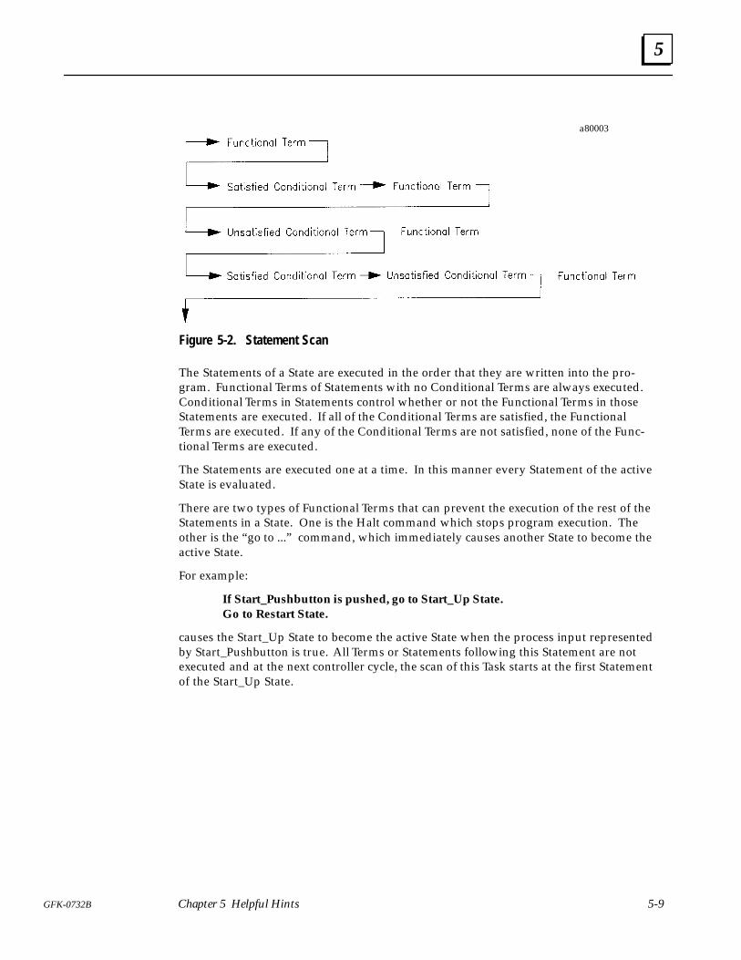
5
5-9GFK-0732B Chapter 5 Helpful Hints
a80003
Figure 5-2. Statement Scan
The Statements of a State are executed in the order that they are written into the pro-gram. Functional Terms of Statements with no Conditional Terms are always executed.Conditional Terms in Statements control whether or not the Functional Terms in thoseStatements are executed. If all of the Conditional Terms are satisfied, the FunctionalTerms are executed. If any of the Conditional Terms are not satisfied, none of the Func-tional Terms are executed.
The Statements are executed one at a time. In this manner every Statement of the activeState is evaluated.
There are two types of Functional Terms that can prevent the execution of the rest of theStatements in a State. One is the Halt command which stops program execution. Theother is the “go to ...” command, which immediately causes another State to become theactive State.
For example:
If Start_Pushbutton is pushed, go to Start_Up State.Go to Restart State.
causes the Start_Up State to become the active State when the process input representedby Start_Pushbutton is true. All Terms or Statements following this Statement are notexecuted and at the next controller cycle, the scan of this Task starts at the first Statementof the Start_Up State.

5
5-10 ECLiPS English Control Language Programming System User’s Guide – March 1998 GFK-0732B
Figure 5-3. Program Scan with GO Terms
Satisfied Conditional Term Unsatisfied Conditional Term Functional Term
Figure 5-4. Statement Scan with GO Terms
During the program scan any changes to variable and analog values are made immedi-ately. Therefore, a variable change in one Task is visible by the rest of the program dur-ing the same scan. On the other hand, digital I/O and Flag conditions are made at theend of the scan. Therefore, if one Task makes a change to the condition of a digital out-put or Flag, the condition cannot be tested by another Task until the next scan throughthe program.

5
5-11GFK-0732B Chapter 5 Helpful Hints
Hints for Using ECLiPS Features
How to Use the ECLiPS Menus
There is one starting menu for each mode of ECLiPS. Press <F3> to view the mainmenu when in Program Mode or Debug Mode.
Options are selected from all ECLiPS menus in the same manner. Use the up and downarrow keys to highlight the option and press the <Enter> key. A quicker method ofmaking a selection is to press the highlighted letter of the desired option. Each optionhas a letter (usually the first letter) that is displayed in a different color or highlighted(for monochrome monitors).
Using ECLiPS Hot Keys
The most popular menu options may be selected without using any menus by pressing aHot Key. Any Hot Keys are listed to the right of the option on the menu where the op-tion is displayed. A full listing of all key functions is available at any time by pressing thehelp key <F1> twice
The Reference chapter of this manual has a table of Hot Keys in the Keyboard Defini-tions chapter. Notice that the Hot Keys are assigned in a manner to make it easy to re-member their functions. All of the Hot Keys which refer to options from the ProjectMenu use the <F2> key. The <Ctrl> key plus letters refer to options from the ListMenu or for Debug Mode selections, for example <Ctrl + D> lists the Digital Points de-fined in the program. The <F4> key is used for Define Menu options; the <F5> key isused for the Find Menu options, <F6> for Add Menu options, and <F8> for the Textoptions.
ECLiPS Word Processing Functions
A program developed using ECLiPS is simply a document of ASCII text. The ECLiPSeditor is fundamentally a word processor with specialized functions for editing a StateLogic program.
The Text option offered on the Program Mode Menu is very useful for manipulatingblocks of program text. The Text functions are used to copy, move, and delete blocks.These functions are very useful for manipulating blocks of the program.
When any of the Text functions are used, the block defined is saved in memory. Thismemory location is called the Paste Buffer. The Paste Buffer always contains the lastblock highlighted for any of the Text operations. The contents of the Paste Buffer are’pasted’ into the program at the cursor location by pressing the <Ctrl + U> keys. ThePASTE function may be used to move or copy blocks of text. The PASTE function is alsouseful for copying blocks from one program to another.
Use the following steps to copy a block from one program to another program.
� Press <F8>, the Hot Key for the Text functions
� Highlight the desired block by using the cursor movement keys
� Press the <Enter> key and choose the COPY option from the menu

5
5-12 ECLiPS English Control Language Programming System User’s Guide – March 1998 GFK-0732B
� Press the <Esc> key to cancel the operation, the paste buffer now has a copy of theblock
� Load another program into ECLiPS
� Press <Ctrl + U> to enter a copy of the block at the cursor location
How to Use ECLiPS Lists
ECLiPS uses lists to display the elements of the control program including I/O points,keywords, filler words, and variable names. The arrow keys and the <Page Up> and<P age Down> keys are used to move through the list. Also use <Ctrl + End> and<Ctrl + Home> to move to the end or the start of the list.
The elements of the list are displayed in alphabetical order. One method to quickly findan element is to enter the letters of the element. When a letter key is pressed, the firstelement starting with that letter is highlighted. Pressing another letter key causes thefirst element starting with those two letters to be highlighted. It is possible to enter all ofthe letters of the element to highlight it, but usually a few letters brings the highlightclose to the target element.
Generally the <Ins> key is used to add, the <Del> key to delete, and the <Esc> key toexit the list. Lists displayed using the “List” option from the Program Mode main menu,also allow the highlighted element to be entered directly into the program at the currentcursor location when the <Enter> key is pressed.
6 section level 1 1figure bi level 1 table_big level 1
6-1GFK-0732B
Chapter 6 Online Tutorial
This chapter is a tutorial that explains the steps necessary to get a control program run-ning in the State Logic Processor. This chapter covers configuring the Series 90-70 CPUwith Logicmaster 90 and how to load, execute, monitor, and interact with an ECLiPScontrol program.
To demonstrate these features, this chapter uses the Conveyor program completed in theProgramming Tutorial chapter of this manual. The I/O definitions of this program mayhave to be changed to be consistent with available I/O hardware or the simulation modecan be used to run the program without being attached to any I/O hardware.
Most of the explanations of this chapter describe the use of ECLiPS Debug Mode. Toview in ECLiPS all of the topics of this chapter, ECLiPS must be connected to a Series90-70 State Logic Processor through the programming port. Not all of the Debug Modeoptions are discussed in this chapter. For a thorough explanation of all Debug Modemenu options see the Debug Mode part of the Reference chapter of this manual.
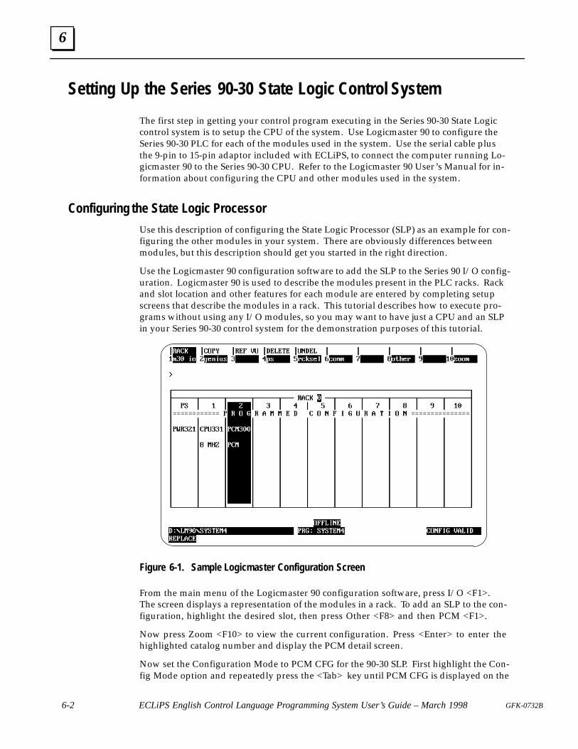
6
6-2 ECLiPS English Control Language Programming System User’s Guide – March 1998 GFK-0732B
Setting Up the Series 90-30 State Logic Control System
The first step in getting your control program executing in the Series 90-30 State Logiccontrol system is to setup the CPU of the system. Use Logicmaster 90 to configure theSeries 90-30 PLC for each of the modules used in the system. Use the serial cable plusthe 9-pin to 15-pin adaptor included with ECLiPS, to connect the computer running Lo-gicmaster 90 to the Series 90-30 CPU. Refer to the Logicmaster 90 User’s Manual for in-formation about configuring the CPU and other modules used in the system.
Configuring the State Logic Processor
Use this description of configuring the State Logic Processor (SLP) as an example for con-figuring the other modules in your system. There are obviously differences betweenmodules, but this description should get you started in the right direction.
Use the Logicmaster 90 configuration software to add the SLP to the Series 90 I/O config-uration. Logicmaster 90 is used to describe the modules present in the PLC racks. Rackand slot location and other features for each module are entered by completing setupscreens that describe the modules in a rack. This tutorial describes how to execute pro-grams without using any I/O modules, so you may want to have just a CPU and an SLPin your Series 90-30 control system for the demonstration purposes of this tutorial.
Figure 6-1. Sample Logicmaster Configuration Screen
From the main menu of the Logicmaster 90 configuration software, press I/O <F1>.The screen displays a representation of the modules in a rack. To add an SLP to the con-figuration, highlight the desired slot, then press Other <F8> and then PCM <F1>.
Now press Zoom <F10> to view the current configuration. Press <Enter> to enter thehighlighted catalog number and display the PCM detail screen.
Now set the Configuration Mode to PCM CFG for the 90-30 SLP. First highlight the Con-fig Mode option and repeatedly press the <Tab> key until PCM CFG is displayed on the

6
6-3GFK-0732B Chapter 6 Online Tutorial
screen. The serial ports are under program control and the parameters are initialized bythe State Logic Processor.
Now press the <Esc> key to save the configuration and return to the rack display. Thedisplay should now show a PCM in the correct slot. Send the configuration to the PLCCPU and the configuration is complete.
Enter the Initialization Ladder Program
Because many of the CPU memory types are retentive (hold their value over a poweroutage), there must be a Ladder Logic program in the CPU which clears memory loca-tions on power up, so that outputs that are ON when power is lost are not ON againwhen power returns. The program to clear the memory locations is included on theECLiPS distribution disks. Follow the instructions in the Reference chapter of this manu-al on Clearing Outputs on Power Up. This section is in the Series 90-30 State Logic Con-trol System part, check the Table of Contents for the Reference chapter.
Enable Outputs and Start Program Running
During program execution the CPU must be in run mode with the outputs enabled. UseLogicmaster 90 to set the status of the CPU before executing the State Logic program.
To start the Series 90-30 CPU running the outputs with output scanning enabled followthese steps from the Logicmaster 90 first screen.
1. Press <F2> for the configuration package.
2. Press <F3> for the PLC Control and Status Screen.
3. Press <F1> for the RUN/STOP PLC Screen.
4. Press <TAB> until RUN/OUT EN is displayed in the highlighted block.
DownLoad a Program
To download a completed program to the State Engine, the ECLiPS computer must beconnected with a serial cable to the SLP programming port, which is port 1 by default.Use the serial cable included with ECLiPS along with the appropriate adaptors for yoursystem.
To download the program, choose the PROJECT choice from the Program Mode menu,then the “Download Project to the Controller” option. ECLiPS now provides the optionof checking the program for undefined words. Choose either yes or no. If there are anyerrors in the program a message is displayed in the bottom bar of the screen. Use <Alt+ F> to access help information describing the error. Follow this procedure to down-load the Conveyor program discussed in the Programming Tutorial chapter of thismanual.
After a successful download a screen displaying the statistics of the project is displayed.Strike any key to go on line, i.e., enter Debug Mode. The usual way to change modes isusing the <F10> key. Try hitting the <F10> key now to change modes back to the Pro-gram Mode. Hit <F10> again to return to Debug Mode.
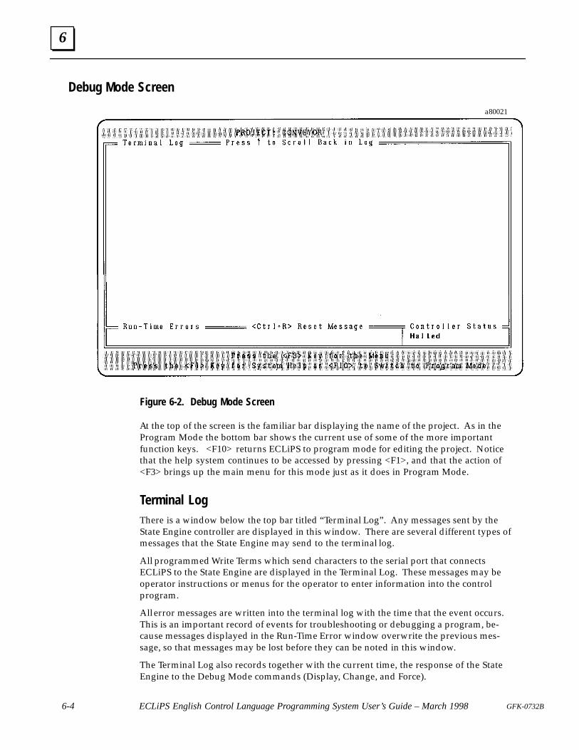
6
6-4 ECLiPS English Control Language Programming System User’s Guide – March 1998 GFK-0732B
Debug Mode Screen
a80021
Figure 6-2. Debug Mode Screen
At the top of the screen is the familiar bar displaying the name of the project. As in theProgram Mode the bottom bar shows the current use of some of the more importantfunction keys. <F10> returns ECLiPS to program mode for editing the project. Noticethat the help system continues to be accessed by pressing <F1>, and that the action of<F3> brings up the main menu for this mode just as it does in Program Mode.
Terminal LogThere is a window below the top bar titled “Terminal Log” . Any messages sent by theState Engine controller are displayed in this window. There are several different types ofmessages that the State Engine may send to the terminal log.
All programmed Write Terms which send characters to the serial port that connectsECLiPS to the State Engine are displayed in the Terminal Log. These messages may beoperator instructions or menus for the operator to enter information into the controlprogram.
All error messages are written into the terminal log with the time that the event occurs.This is an important record of events for troubleshooting or debugging a program, be-cause messages displayed in the Run-Time Error window overwrite the previous mes-sage, so that messages may be lost before they can be noted in this window.
The Terminal Log also records together with the current time, the response of the StateEngine to the Debug Mode commands (Display, Change, and Force).
6
6-5GFK-0732B Chapter 6 Online Tutorial
The first message is displayed at the top of this window with the next messages appear-ing below the previous ones. The oldest messages scroll out the top of the windowwhen the window fills. Messages scrolled off the screen can still be viewed by pressingthe up arrow key. After scrolling, you must press <End> to exit the scroll mode andagain have access to the Debug Mode menu.
Error and Status WindowsThere are two windows on the line below the Terminal Log window. The one on the leftdisplays any run time error messages such as a divide by zero message or an open circuitfault message. Notice that the error message is cleared by pressing <Ctrl + R>. Thesmaller window on the right displays the current status of the controller, i.e., running orhalted. The status window also indicates when a discrete or analog I/O point is forced.
Put SLP in Run Mode
Press <F3> to view the menu, then select the “Project” option. Use this menu to put theSLP in Simulation Mode and start the Conveyor program running. Use the SimulationMode to run the program without interacting with any I/O hardware.
Toggle Simulation Mode
Simulation Mode is used to disconnect the actual I/O from a running program. Thismode is useful to test a program before actually connecting to the real world and to trou-bleshoot an existing program by disconnecting the machine from the State Engine con-troller. If you are using simulation mode for this tutorial, select this option from thePROJECT menu now. The controller must be in Halt Mode to activate the SimulationMode.
RUN or HALT Program
Use these menu options on the PROJECT menu to start or stop program execution. Startthe program running now.
Controlling and Observing the Fill Station
This section describes the features available to control and examine program execution.These examples assume that the State Logic Processor is executing in Simulation Mode,although these exercises are more informative using real world I/O.
The program must be exercised to observe how it executes. First lets create a monitortable to watch the program change States.
Monitor
Bring up the menu with the <F3> key. Next press <M> to get the Monitor menu. Se-lect the “Add a New Monitor Table” option, and enter States for the name of the Monitortable. Select the “Current State of a Task” option from the list of categories to monitor.
6
6-6 ECLiPS English Control Language Programming System User’s Guide – March 1998 GFK-0732B
One at a time select each of the Task Names to monitor by highlighting the name in thelist and pressing <Enter>. Now continue to press <Esc> until a monitor table is dis-played at the bottom of the screen.
ViewNow we are ready to have the program go through its steps. First lets display the pro-gram. Select the “View” option from the menu, and then select the “View English Text inCurrent Task Group” option. Notice <Ctrl + V> is the hot key for this selection.
With the arrow key move the cursor to the word Can_At_Fill and press the <Alt + F>key as shown in the bottom bar for functions. Choose the “Look up the Current Wordand Display its Value” option. Notice the resulting window displays the word definitionplus its current value. This option is also invoked by pressing the hot key <F4>.
Press <C> to change the value. From the resulting window force Can_At_Fill ON. No-tice that the Fill Station Task is now in the Pour_Chem_1 State. Now move the cursor tothe word Chem_Valve_1 and press the hot key <F4>. Chem_Valve_1 is ON as it shouldbe when Pour_Chem_1 State of the Fill_Station Task is active.
Now move the cursor to the Fill_Weight_Input word and press <F4>, then change theanalog input to 20.1. The current State is now Pour_Chem_2. Check the condition ofChem_Valve_2 and Chem_Valve_1. Change Fill_Weight_Input to 30.1 to go to theWait_For_Can_Removal State. Put the cursor on Can_At_Fill again and clear the forcedcondition so that Fill_Station Task goes back to the PowerUp State. Remember to changethe Fill_Weight_Input back to zero before repeating this cycle.
Controlling and Observing the Mix StationIn this section we explore other ways to change elements of the program and watch theresults of those changes. First lets create a more detailed monitor table. Select the “Add aNew Monitor Table” option again and call it Mix Station.
Enter all of the digital points used in the Mix Station Task:
Can_At_Mix��� ���������
��� ����������
��� �����
��� ��������
��� ���������
ChangeNow select the “Change” option from the menu. This option allows changes to otherelements of the program. Select the “Current State of a Task” option. Now select theMix_Station from the list of Tasks , and then select Lower_Mixer from the list of States. Amessage is displayed in the Terminal Log, stating the action that was executed and thecurrent time. Notice that the Mixer_Down_Motor is now ON. Also note that if thisState stays active for more than 20 seconds the Max_Time message is displayed in theRun-Time Error window and in the Terminal Log.
DisplayNow select the “Display” option from the menu. Several types of program informationcan be displayed from this menu. Select the “Current State of a Task” option, and then
6
6-7GFK-0732B Chapter 6 Online Tutorial
the Mix_Station Task from the list of Tasks. The display in the Terminal Log shows thatthe Current State is Lower_Mixer and the time.
Force
Now select the “Force” option from the menu and then “Set or Modify Force List” . Awindow appears that shows all of the items forced and their current value. Press <Ins>to add an item to the list, and then select “Digital Points” . Select the Mix-er_Down_Switch and force it ON. The Mix_Station Task goes to the Mix_ChemicalsState, notice the Mixer_Motor goes ON for 10 seconds and then the Mixer_Up_Motorcomes ON. Force the Mixer_Up_Switch ON and the program goes to Wait_For_Can_Re-moval State and on the next scan to the PowerUp State, since the Can_At_Mix input isOFF.
Trace
To see a history of the execution of the program, select the “Trace” option from themenu. Select the “Upload Trace from Controller” option to see the Trace display.
The top line gives the time and date of the upload. Next a table of State changes is dis-played, showing the starting State and the resulting State and which Task, with the mostcurrent State change at the top of the list.
The Trace display is a valuable tool for debugging and troubleshooting a program. TheTasks for which State changes are displayed can be changed so that unwanted changesare not included.
PLC I/O
It is often desirable to see what I/O memory locations are assigned to the programnames. To inspect the names and definitions, select “PLC I/O” from the menu. Selectthe memory type and then the name from the list for the form that lists the I/O name,type, number, and input or output.
PID Loop Tuning Screen
This option only appears in the Debug Mode menu when the program loaded into theState Engine has a PID loop defined. After choosing this option, a list of defined PIDloops is displayed. Select the desired PID loop from the list to use the tuning screen.
The tuning screen displays the values of the PID parameters and the status of the loop.The values are continuously updated as they change. Use this screen to tune the loop bychanging parameter values.
Viewing and Clearing CPU Faults
Select the option for CPU faults to list the current fault table in the CPU. Both the PLCfaults and the I/O faults can be displayed. You may clear the fault tables from this dis-play. Note that the fault tables are not available when running in simulation mode.
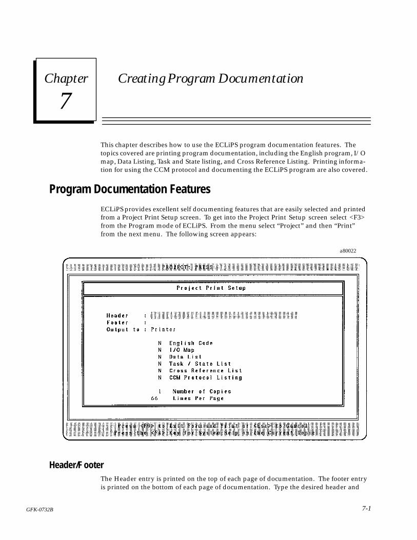
7 section level 1 1figure bi level 1 table_big level 1
7-1GFK-0732B
Chapter 7 Creating Program Documentation
This chapter describes how to use the ECLiPS program documentation features. Thetopics covered are printing program documentation, including the English program, I/Omap, Data Listing, Task and State listing, and Cross Reference Listing. Printing informa-tion for using the CCM protocol and documenting the ECLiPS program are also covered.
Program Documentation FeaturesECLiPS provides excellent self documenting features that are easily selected and printedfrom a Project Print Setup screen. To get into the Project Print Setup screen select <F3>from the Program mode of ECLiPS. From the menu select “Project” and then “Print”from the next menu. The following screen appears:
a80022
Header/F ooterThe Header entry is printed on the top of each page of documentation. The footer entryis printed on the bottom of each page of documentation. Type the desired header and

7
7-2 ECLiPS English Control Language Programming System User’s Guide – March 1998 GFK-0732B
footer information in the highlighted box. The Header and Footer will accept up to 40characters of information.
Directing the Output
The “Output To:” option specifies where the documentation is to be sent. If “Printer” isentered for this option, the documentation is sent to the printer connected to the parallelport. ECLiPS interprets any other name entered for this option to be a file name and theselected documentation options are sent to a disk to be stored in a file.
Documentation Options
This section describes each of the documentation options and shows a sample of thedocumentation produced when the option is selected. The Up and Down arrow keysare used to move the highlighted cursor to the options. To have a selection printed withthe documentation package type a <Y> next to the option to be printed or a <N> tosuppress a selection from being printed. Actually pressing any other key causes the formto toggle the display between Y and N for the highlighted option. For the “Number ofCopies” and lines per page options type in the appropriate number. Press <ENTER>after selecting the number of packages to print. Press <F9> to start printing the docu-mentation out the host computer’s parallel port.
English CodeThe ECLiPS program is printed when this option is selected. The name of the projectand the date and time that the program was last modified is printed at the top of thepage. A page number is printed at the bottom of the page. An example is listed below:
�/-(#!1� �������� ��01 �-"'$'#"� 5�5�� ��
��0)� �'**��1�1'-,
�1�1#� �-4#/�.
�$ ��,� 1��'** '0 -,� %- 1- �-2/��&#+���1�1#�
�1�1#� �-2/��&#+��
�.#, �&#+���*3#���
�$ �'**��#'%&1��,.21 '0 � -3# �� .-2,"0�
�&#, %- 1- ��'1�$-/���,��#+-3�*�
Ñ
Ñ
Ñ
�'3#/0'"# �*�,1 ��%# �
����� ����
I/O MapThe I/O Map is a list of all of the names of CPU memory types defined in the State Logicprogram. The types included are %I, %Q, %AI, %AQ, %T, %M, %G, %S, %SA, %SB,
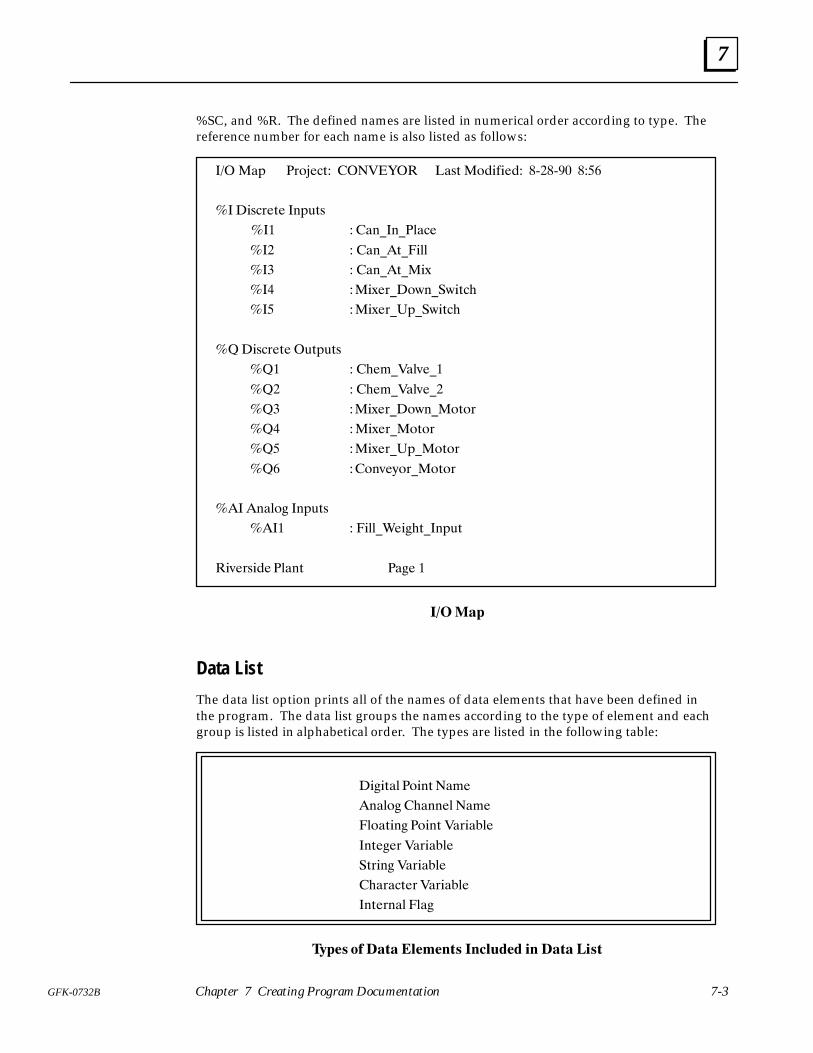
7
7-3GFK-0732B Chapter 7 Creating Program Documentation
%SC, and %R. The defined names are listed in numerical order according to type. Thereference number for each name is also listed as follows:
��� �!/ �0.*%#2 �������� �!12 �.$)&)%$ �8��8�� �
�� �)1#0%2% �-/321
��� �!- �- �+!#%
��� �!- �2 �)++
��� �!- �2 �)6
��� �)6%0 �.5- �5)2#(
�� �)6%0 �/ �5)2#(
���)1#0%2% �32/321
��� �(%, �!+4% �
��� �(%, �!+4% �
��� �)6%0 �.5- �.2.0
��� �)6%0 �.2.0
�� �)6%0 �/ �.2.0
�� �.-4%7.0 �.2.0
��� �-!+.' �-/321
���� �)++ �%)'(2 �-/32
�)4%01)$% �+!-2 �!'% �
�����
Data List
The data list option prints all of the names of data elements that have been defined inthe program. The data list groups the names according to the type of element and eachgroup is listed in alphabetical order. The types are listed in the following table:
�)')2!+ �.)-2 �!,%
�-!+.' �(!--%+ �!,%
�+.!2)-' �.)-2 �!0)!"+%
�-2%'%0 �!0)!"+%
�20)-' �!0)!"+%
�(!0!#2%0 �!0)!"+%
�-2%0-!+ �+!'
�� � �� �� �� � ��� ������ � �� �� ����
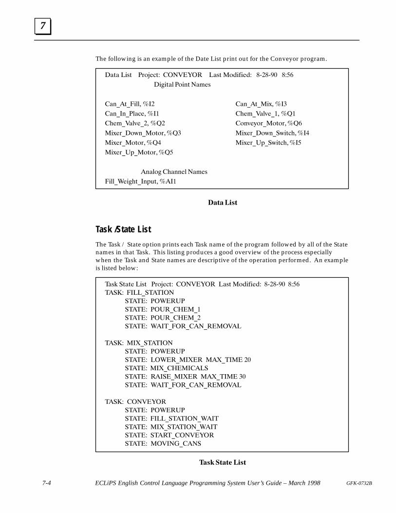
7
7-4 ECLiPS English Control Language Programming System User’s Guide – March 1998 GFK-0732B
The following is an example of the Date List print out for the Conveyor program.
�&7& �-67 �53.)'7 ���!�$�� �&67 �3(-*-)( �=��=�� �
�-+-7&0 �3-27 �&1)6
�&2%�7%�-00� ��� �&2%�7%�-;� ���
�&2%�2%�0&')� ��� �,)1%!&09)%�� ���
�,)1%!&09)%�� ��� �329)<35%�3735���
�-;)5%�3:2%�3735���� �-;)5%�3:2%�:-7',����
�-;)5%�3735���� �-;)5% 4%�:-7',���
�-;)5% 4%�3735���
�2&03+ �,&22)0 �&1)6
�-00%")-+,7%�2487�����
�������
Task /State List
The Task / State option prints each Task name of the program followed by all of the Statenames in that Task. This listing produces a good overview of the process especiallywhen the Task and State names are descriptive of the operation performed. An exampleis listed below:
�&6/ �7&7) �-67 �53.)'7 ���!�$�� �&67 �3(-*-)( �=��=�� �
���� ����%�������
����� ��"�� �
����� �� �%����%�
����� �� �%����%�
����� "���%���%���%����!��
���� ��#%�������
����� ��"�� �
����� ��"��%��#�� ��#%���� ��
����� ��#%���������
����� �����%��#�� ��#%���� ��
����� "���%���%���%����!��
���� ���!�$��
����� ��"�� �
����� ����%�������%"���
����� ��#%�������%"���
����� �����%���!�$��
����� ��!���%����
�� ����� ���
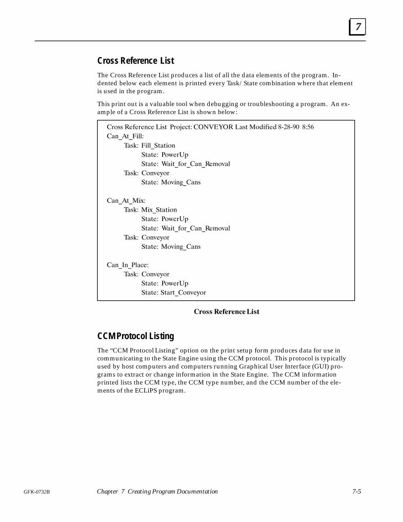
7
7-5GFK-0732B Chapter 7 Creating Program Documentation
Cross Reference ListThe Cross Reference List produces a list of all the data elements of the program. In-dented below each element is printed every Task/State combination where that elementis used in the program.
This print out is a valuable tool when debugging or troubleshooting a program. An ex-ample of a Cross Reference List is shown below:
)'** ����)�&�� �!*+ �)'"��+� ������� ��*+ �'�!�!�� �0��0�� ����
�&�+��!$$�
��*#� �!$$��+�+!'&
�+�+�� �'-�)�(
�+�+�� ��!+��')��&���%',�$
��*#� '&,�/')
�+�+�� �',!& ��&*
�&�+��!.�
��*#� �!.��+�+!'&
�+�+�� �'-�)�(
�+�+�� ��!+��')��&���%',�$
��*#� '&,�/')
�+�+�� �',!& ��&*
�&� &��$����
��*#� '&,�/')
�+�+�� �'-�)�(
�+�+�� �+�)+�'&,�/')
���� �����������
CCM Protocol ListingThe “CCM Protocol Listing” option on the print setup form produces data for use incommunicating to the State Engine using the CCM protocol. This protocol is typicallyused by host computers and computers running Graphical User Interface (GUI) pro-grams to extract or change information in the State Engine. The CCM informationprinted lists the CCM type, the CCM type number, and the CCM number of the ele-ments of the ECLiPS program.
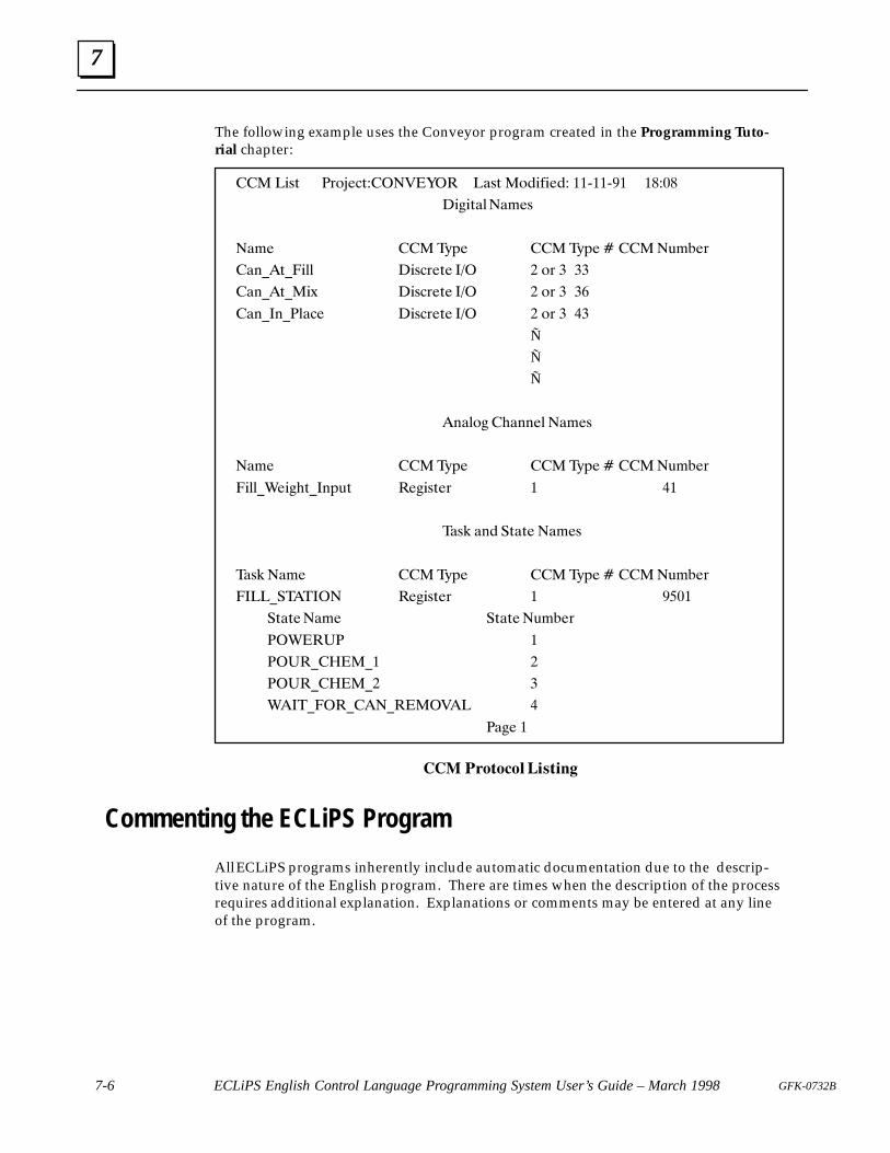
7
7-6 ECLiPS English Control Language Programming System User’s Guide – March 1998 GFK-0732B
The following example uses the Conveyor program created in the Programming Tuto-rial chapter:
��� �*34 �20+&$4 ����� �� �"34 �0%*'*&% ��8��8�� �� ��
�*(*4"-�".&3
�".& ����71& ����71& � ����5.#&2
�"/!�4!�*-- �*3$2&4& ��� � 02 � ��
�"/!�4!�*6 �*3$2&4& ��� � 02 � �
�"/!�/!�-"$& �*3$2&4& ��� � 02 � ��
Ñ
Ñ
Ñ
�/"-0( �)"//&- �".&3
�".& ����71& ����71& � ����5.#&2
�*--!�&*()4!�/154 �&(*34&2 � ��
�"3, "/% �4"4& �".&3
�"3, �".& ����71& ����71& � ����5.#&2
����!������� �&(*34&2 � ���
�4"4&�".& �4"4&�5.#&2
������� �
����!����!� �
����!����!� �
����!���!���!������� �
�"(& �
��� ������� �� ���
Commenting the ECLiPS Program
All ECLiPS programs inherently include automatic documentation due to the descrip-tive nature of the English program. There are times when the description of the processrequires additional explanation. Explanations or comments may be entered at any lineof the program.
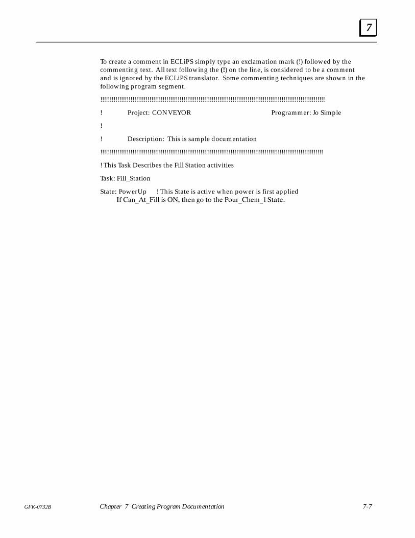
7
7-7GFK-0732B Chapter 7 Creating Program Documentation
To create a comment in ECLiPS simply type an exclamation mark (!) followed by thecommenting text. All text following the (!) on the line, is considered to be a commentand is ignored by the ECLiPS translator. Some commenting techniques are shown in thefollowing program segment.
!!!!!!!!!!!!!!!!!!!!!!!!!!!!!!!!!!!!!!!!!!!!!!!!!!!!!!!!!!!!!!!!!!!!!!!!!!!!!!!!!!!!!!!!!!!!!!!!!!!!!!!!!!!!!!!!!!!!!!!
! Project: CONVEYOR Programmer: Jo Simple
!
! Description: This is sample documentation
!!!!!!!!!!!!!!!!!!!!!!!!!!!!!!!!!!!!!!!!!!!!!!!!!!!!!!!!!!!!!!!!!!!!!!!!!!!!!!!!!!!!!!!!!!!!!!!!!!!!!!!!!!!!!!!!!!!!!!
! This Task Describes the Fill Station activities
Task: Fill_Station
State: PowerUp ! This State is active when power is first applied �� ��� �� ���� �� � ���� �� �� ��� ���� ���� �������

8 section level 1 1figure bi level 1 table_big level 1
8-1GFK-0732B
Chapter 8 Reference
This chapter is designed to provide information about the details of the ECLiPS controllanguage and how to use the ECLiPS software package. The chapter starts with a de-scription of the State Logic Language and Keywords then discusses the setup of the Se-ries 90-70 control system, then each of the menu options is explained, and finally theECLiPS specifications are displayed.
Language Description
This chapter describes the details of using English to create a control program. The de-tailed information describes how to structure the English program using keywords, fillerwords, names, references to I/O, programming PID Loops, grammatical rules, and spe-cial “perform” functions.
Program StructureThere is a hierarchy in the structure of an ECLiPS program. Each program is dividedinto one or more Tasks, each Task is divided into one or more States, etc. The figure be-low lists each element of the hierarchy in descending order of significance.
ProgramTaskStateStatementExpressionTerm Word
ECLiPS Program Hierarchy
This hierarchy of Tasks, States, and Statements are explained in chapters 2 and 3 of thismanual. A program is a collection of Tasks, and Tasks are a collection of States which de-scribe a sequence of actions. There may be many Tasks all executing simultaneously.Each State is described by one or more Statements and each Statement consists of Ex-pressions. Expressions are constructed from Terms which are composed of words.
In the program each Task begins with the keyword, Task, followed by a colon then aTask Name.
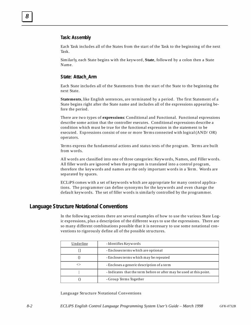
8
8-2 ECLiPS English Control Language Programming System User’s Guide – March 1998 GFK-0732B
Task: Assembly
Each Task includes all of the States from the start of the Task to the beginning of the nextTask.
Similarly, each State begins with the keyword, State, followed by a colon then a StateName.
State: Attach_Arm
Each State includes all of the Statements from the start of the State to the beginning thenext State.
Statements, like English sentences, are terminated by a period. The first Statement of aState begins right after the State name and includes all of the expressions appearing be-fore the period.
There are two types of expressions: Conditional and Functional. Functional expressionsdescribe some action that the controller executes. Conditional expressions describe acondition which must be true for the functional expression in the statement to beexecuted. Expressions consist of one or more Terms connected with logical (AND/OR)operators.
Terms express the fundamental actions and status tests of the program. Terms are builtfrom words.
All words are classified into one of three categories: Keywords, Names, and Filler words.All filler words are ignored when the program is translated into a control program,therefore the keywords and names are the only important words in a Term. Words areseparated by spaces.
ECLiPS comes with a set of keywords which are appropriate for many control applica-tions. The programmer can define synonyms for the keywords and even change thedefault keywords. The set of filler words is similarly controlled by the programmer.
Language Structure Notational Conventions
In the following sections there are several examples of how to use the various State Log-ic expressions, plus a description of the different ways to use the expressions. There areso many different combinations possible that it is necessary to use some notational con-ventions to rigorously define all of the possible structures.
Underline - Identifies Keywords
[] - Encloses terms which are optiona�
{} - Encloses terms which may be repeated
<> - Encloses a generic description of a term
| - Indicates that the term before or after may be used at this point.
() - Group Terms Together
Language Structure Notational Conventions
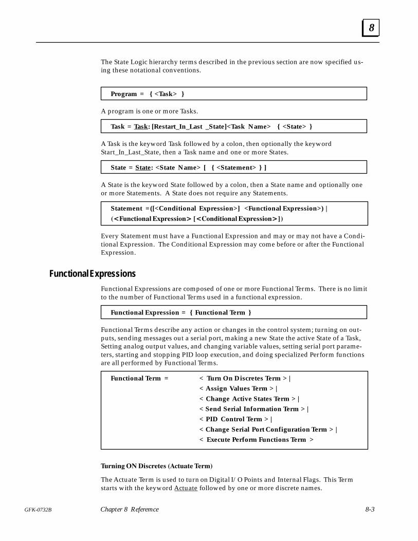
8
8-3GFK-0732B Chapter 8 Referemce
The State Logic hierarchy terms described in the previous section are now specified us-ing these notational conventions.
Program = { <Task> }
A program is one or more Tasks.
Task = Task: [Restart_In_Last _State]<Task Name> { <State> }
A Task is the keyword Task followed by a colon, then optionally the keywordStart_In_Last_State, then a Task name and one or more States.
State = State: <State Name> [ { <Statement> } ]
A State is the keyword State followed by a colon, then a State name and optionally oneor more Statements. A State does not require any Statements.
Statement =([<Conditional Expression>] <Functional Expression>) |
����������������������������������������������
Every Statement must have a Functional Expression and may or may not have a Condi-tional Expression. The Conditional Expression may come before or after the FunctionalExpression.
Functional ExpressionsFunctional Expressions are composed of one or more Functional Terms. There is no limitto the number of Functional Terms used in a functional expression.
Functional Expression = { Functional Term }
Functional Terms describe any action or changes in the control system; turning on out-puts, sending messages out a serial port, making a new State the active State of a Task,Setting analog output values, and changing variable values, setting serial port parame-ters, starting and stopping PID loop execution, and doing specialized Perform functionsare all performed by Functional Terms.
Functional Term = < Turn On Discretes Term > |
< Assign Values Term > |
< Change Active States Term > |
< Send Serial Information Term > |
< PID Control Term > |
< Change Serial Port Configuration Term > |
< Execute Perform Functions Term >
������ ����������� �������� ����
The Actuate Term is used to turn on Digital I/O Points and Internal Flags. This Termstarts with the keyword Actuate followed by one or more discrete names.
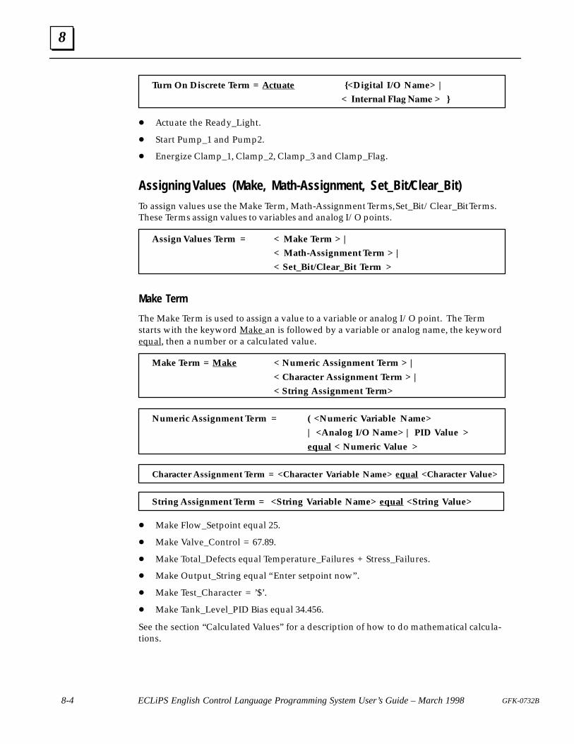
8
8-4 ECLiPS English Control Language Programming System User’s Guide – March 1998 GFK-0732B
Turn On Discrete Term = Actuate {<Digital I/O Name> |
< ������ ���� ��� > }
� Actuate the Ready_Light.
� Start Pump_1 and Pump2.
� Energize Clamp_1, Clamp_2, Clamp_3 and Clamp_Flag.
Assigning Values (Make, Math-Assignment, Set_Bit/Clear_Bit)To assign values use the Make Term, Math-Assignment Terms, Set_Bit/Clear_Bit Terms.These Terms assign values to variables and analog I/O points.
Assign Values Term = < Make Term > |
< Math-Assignment Term > |
< Set_Bit/Clear_Bit Term >
Make Term
The Make Term is used to assign a value to a variable or analog I/O point. The Termstarts with the keyword Make an is followed by a variable or analog name, the keywordequal, then a number or a calculated value.
Make Term = Make < Numeric Assignment Term > |
< Character Assignment Term > |
< String Assignment Term>
Numeric Assignment Term = ( <Numeric Variable Name>
| <Analog I/O Name> | PID Value >
equal < Numeric Value >
Character Assignment Term = <Character Variable Name> equal <Character Value>
String Assignment Term = <String Variable Name> equal <String Value>
� Make Flow_Setpoint equal 25.
� Make Valve_Control = 67.89.
� Make Total_Defects equal Temperature_Failures + Stress_Failures.
� Make Output_String equal “Enter setpoint now” .
� Make Test_Character = ’$’.
� Make Tank_Level_PID Bias equal 34.456.
See the section “Calculated Values” for a description of how to do mathematical calcula-tions.
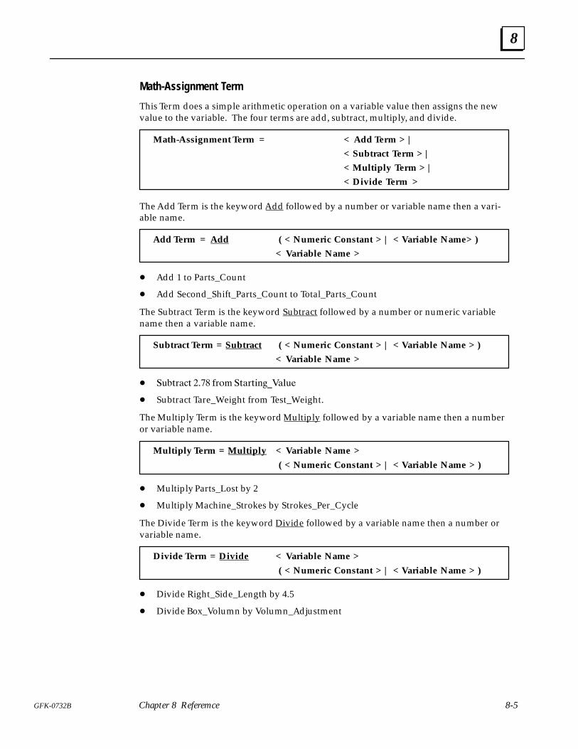
8
8-5GFK-0732B Chapter 8 Referemce
Math-Assignment Term
This Term does a simple arithmetic operation on a variable value then assigns the newvalue to the variable. The four terms are add, subtract, multiply, and divide.
Math-Assignment Term = < Add Term > |
< Subtract Term > |
< Multiply Term > |
< Divide Term >
The Add Term is the keyword Add followed by a number or variable name then a vari-able name.
Add Term = Add ( < Numeric Constant > | < Variable Name> )
< Variable Name >
� Add 1 to Parts_Count
� Add Second_Shift_Parts_Count to Total_Parts_Count
The Subtract Term is the keyword Subtract followed by a number or numeric variablename then a variable name.
Subtract Term = Subtract ( < Numeric Constant > | < Variable Name > )
< Variable Name >
� ������ ���� ��� ������������
� Subtract Tare_Weight from Test_Weight.
The Multiply Term is the keyword Multiply followed by a variable name then a numberor variable name.
Multiply Term = Multiply < Variable Name >
( < Numeric Constant > | < Variable Name > )
� Multiply Parts_Lost by 2
� Multiply Machine_Strokes by Strokes_Per_Cycle
The Divide Term is the keyword Divide followed by a variable name then a number orvariable name.
Divide Term = Divide < Variable Name >
( < Numeric Constant > | < Variable Name > )
� Divide Right_Side_Length by 4.5
� Divide Box_Volumn by Volumn_Adjustment
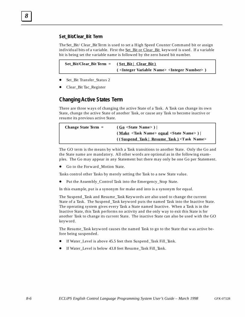
8
8-6 ECLiPS English Control Language Programming System User’s Guide – March 1998 GFK-0732B
Set_Bit/Clear_Bit Term
The Set_Bit/Clear_Bit Term is used to set a High Speed Counter Command bit or assignindividual bits of a variable. First the Set_Bit or Clear_Bit keyword is used. If a variablebit is being set the variable name is followed by the zero based bit number.
Set_Bit/Clear_Bit Term = ( Set_Bit | Clear_Bit )
( <Integer Variable Name> <Integer Number> )
� Set_Bit Transfer_Status 2
� Clear_Bit Tac_Register
Changing Active States TermThere are three ways of changing the active State of a Task. A Task can change its ownState, change the active State of another Task, or cause any Task to become inactive orresume its previous active State.
Change State Term = ( Go <State Name> ) |
( Make <Task Name> equal <State Name> ) |
( ( Suspend_Task | Resume_Task ) <Task Name>
The GO term is the means by which a Task transitions to another State. Only the Go andthe State name are mandatory. All other words are optional as in the following exam-ples. The Go may appear in any Statement but there may only be one Go per Statement.
� Go to the Forward_Motion State.
Tasks control other Tasks by merely setting the Task to a new State value.
� Put the Assembly_Control Task into the Emergency_Stop State.
In this example, put is a synonym for make and into is a synonym for equal.
The Suspend_Task and Resume_Task Keywords are also used to change the currentState of a Task. The Suspend_Task keyword puts the named Task into the Inactive State.The operating system gives every Task a State named Inactive. When a Task is in theInactive State, this Task performs no activity and the only way to exit this State is foranother Task to change its current State. The inactive State can also be used with the GOkeyword.
The Resume_Task keyword causes the named Task to go to the State that was active be-fore being suspended.
� If Water_Level is above 45.5 feet then Suspend_Task Fill_Tank.
� If Water_Level is below 43.8 feet Resume_Task Fill_Tank.
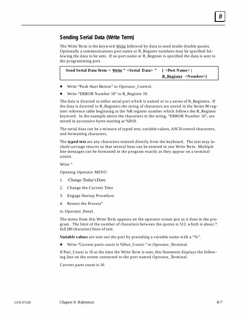
8
8-7GFK-0732B Chapter 8 Referemce
Sending Serial Data (Write Term)The Write Term is the keyword Write followed by data to send inside double quotes.Optionally a communications port name or R_Register numbers may be specified fol-lowing the data to be sent. If no port name or R_Register is specified the data is sent tothe programming port.
Send Serial Data Term = Write ” <Serial Data> ” [ <Port Name> |
R_Register <Number>]
� Write “Push Start Button” to Operator_Control.
� Write “ERROR Number 16” to R_Register 10.
The data is directed to either serial port which is named or to a series of R_Registers. Ifthe data is directed to R_Registers the string of characters are stored in the Series 90 reg-ister reference table beginning at the %R register number which follows the R_Registerkeyword. In the example above the characters in the string, “ERROR Number 16” , arestored in successive bytes starting at %R10.
The serial data can be a mixture of typed text, variable values, ASCII control characters,and formatting characters.
The typed text are any characters entered directly from the keyboard. The text may in-clude carriage returns so that several lines can be entered in one Write Term. Multipleline messages can be formatted in the program exactly as they appear on a terminalscreen.
Write ”
Opening Operator MENU
1. ���� ������ ����
2. Change the Current Time
3. Engage Startup Procedure
4. Restart the Process”
to Operator_Panel.
The menu from this Write Term appears on the operator screen just as it does in the pro-gram. The limit of the number of characters between the quotes is 512, which is about 7full (80 character) lines of text.
Variable values are sent out the port by preceding a variable name with a “%” .
� Write “Current parts count is %Part_Count.” to Operator_Terminal.
If Part_Count is 10 at the time the Write Term is sent, this Statement displays the follow-ing line on the screen connected to the port named Operator_Terminal.
Current parts count is 10.
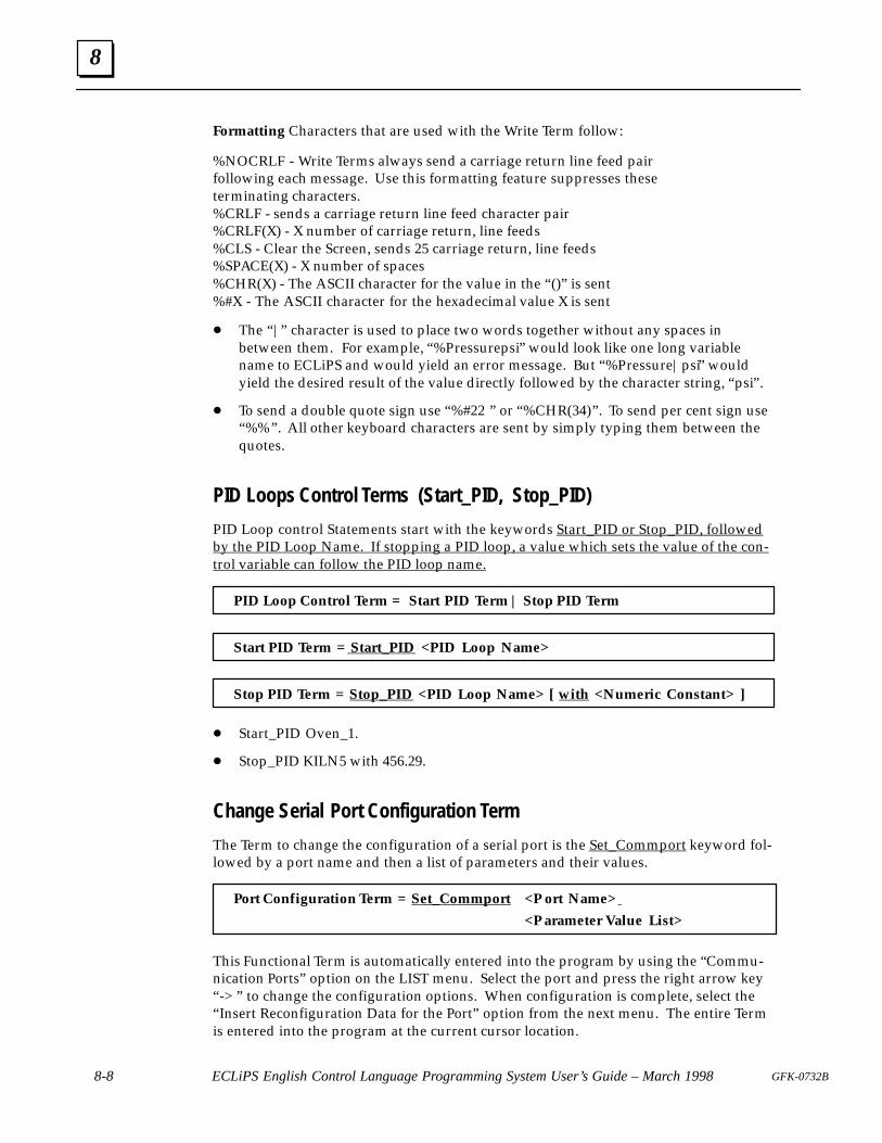
8
8-8 ECLiPS English Control Language Programming System User’s Guide – March 1998 GFK-0732B
Formatting Characters that are used with the Write Term follow:
%NOCRLF - Write Terms always send a carriage return line feed pairfollowing each message. Use this formatting feature suppresses theseterminating characters.%CRLF - sends a carriage return line feed character pair%CRLF(X) - X number of carriage return, line feeds%CLS - Clear the Screen, sends 25 carriage return, line feeds%SPACE(X) - X number of spaces%CHR(X) - The ASCII character for the value in the “ ()” is sent%#X - The ASCII character for the hexadecimal value X is sent
� The “|” character is used to place two words together without any spaces inbetween them. For example, “%Pressurepsi” would look like one long variablename to ECLiPS and would yield an error message. But “%Pressure|psi” wouldyield the desired result of the value directly followed by the character string, “psi” .
� To send a double quote sign use “%#22 ” or “%CHR(34)” . To send per cent sign use“%%” . All other keyboard characters are sent by simply typing them between thequotes.
PID Loops Control Terms (Start_PID, Stop_PID)
PID Loop control Statements start with the keywords Start_PID or Stop_PID, followedby the PID Loop Name. If stopping a PID loop, a value which sets the value of the con-trol variable can follow the PID loop name.
PID Loop Control Term = Start PID Term | Stop PID Term
Start PID Term = Start_PID <PID Loop Name>
Stop PID Term = Stop_PID <PID Loop Name> [ with <Numeric Constant> ]
� Start_PID Oven_1.
� Stop_PID KILN5 with 456.29.
Change Serial Port Configuration Term
The Term to change the configuration of a serial port is the Set_Commport keyword fol-lowed by a port name and then a list of parameters and their values.
Port Configuration Term = Set_Commport <P ort Name>
<P arameter Value List>
This Functional Term is automatically entered into the program by using the “Commu-nication Ports” option on the LIST menu. Select the port and press the right arrow key“ -> ” to change the configuration options. When configuration is complete, select the“ Insert Reconfiguration Data for the Port” option from the next menu. The entire Termis entered into the program at the current cursor location.
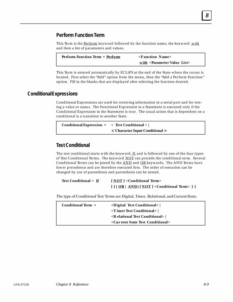
8
8-9GFK-0732B Chapter 8 Referemce
Perform Function TermThis Term is the Perform keyword followed by the function name, the keyword withand then a list of parameters and values.
Perform Function Term = Perform <F unction Name>
with <Parameter Value List>
This Term is entered automatically by ECLiPS at the end of the State where the cursor islocated. First select the “Add” option from the menu, then the “Add a Perform Function”option. Fill in the blanks that are displayed after selecting the function desired.
Conditional Expressions
Conditional Expressions are used for receiving information in a serial port and for test-ing a value or status. The Functional Expression in a Statement is executed only if theConditional Expression in the Statement is true. The usual action that is dependent on aconditional is a transition to another State.
Conditional Expression = < Test Conditional > |
�������� � ��� �� ����� �� �
Test ConditionalThe test conditional starts with the keyword, If, and is followed by one of the four typesof Test Conditional Terms. The keyword NOT can precede the conditional term. SeveralConditional Terms can be joined by the AND and OR keywords. The AND Terms havelower precedence and are therefore executed first. The order of execution can bechanged by use of parenthesis and parenthesis can be nested.
Test Conditional = If [ NOT ] <Conditional Term>
[ { ( OR | AND) [ NOT ] <Conditional Term> } ]
��� ���� �� ��������� ���� ����� �� �� ���� ������ ��������� �������� �����
Conditional Term = <Digital Test Conditional> |
<T imer Test Conditional> |
<R elational Test Conditional> |
<Cur rent State Test Conditional>
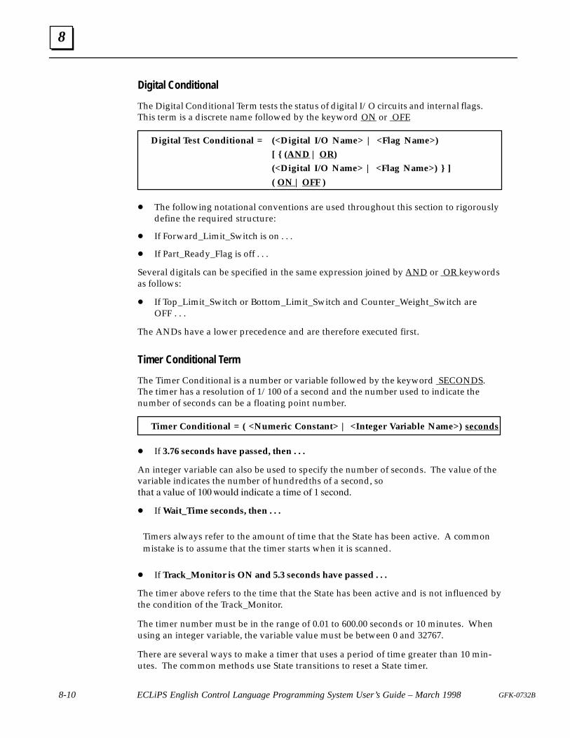
8
8-10 ECLiPS English Control Language Programming System User’s Guide – March 1998 GFK-0732B
Digital Conditional
The Digital Conditional Term tests the status of digital I/O circuits and internal flags.This term is a discrete name followed by the keyword ON or OFF.
Digital Test Conditional = (<Digital I/O Name> | <Flag Name>)
[ { (AND | OR)
(<Digital I/O Name> | <Flag Name>) } ]
( ON | OFF )
� The following notational conventions are used throughout this section to rigorouslydefine the required structure:
� If Forward_Limit_Switch is on . . .
� If Part_Ready_Flag is off . . .
Several digitals can be specified in the same expression joined by AND or OR keywordsas follows:
� If Top_Limit_Switch or Bottom_Limit_Switch and Counter_Weight_Switch areOFF . . .
The ANDs have a lower precedence and are therefore executed first.
Timer Conditional Term
The Timer Conditional is a number or variable followed by the keyword SECONDS.The timer has a resolution of 1/100 of a second and the number used to indicate thenumber of seconds can be a floating point number.
Timer Conditional = ( <Numeric Constant> | <Integer Variable Name>) seconds
� If 3.76 seconds have passed, then . . .
An integer variable can also be used to specify the number of seconds. The value of thevariable indicates the number of hundredths of a second, so ��� � ����� � ��� ����� �������� � �� � � � �������
� If Wait_Time seconds, then . . .
Timers always refer to the amount of time that the State has been active. A commonmistake is to assume that the timer starts when it is scanned.
� If Track_Monitor is ON and 5.3 seconds have passed . . .
The timer above refers to the time that the State has been active and is not influenced bythe condition of the Track_Monitor.
The timer number must be in the range of 0.01 to 600.00 seconds or 10 minutes. Whenusing an integer variable, the variable value must be between 0 and 32767.
There are several ways to make a timer that uses a period of time greater than 10 min-utes. The common methods use State transitions to reset a State timer.
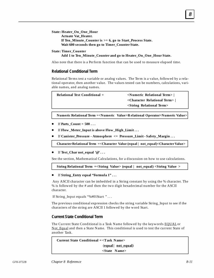
8
8-11GFK-0732B Chapter 8 Referemce
State: Heater_On_One_HourActuate Vat_Heater.If Ten_Minute_Counter is >= 6, go to Start_Process State.Wait 600 seconds then go to Timer_Counter State.
State: Timer_Counter Add 1 to Ten_Minute_Counter and go to Heater_On_One_Hour State.
Also note that there is a Perform function that can be used to measure elapsed time.
Relational Conditional Term
Relational Terms test a variable or analog values. The Term is a value, followed by a rela-tional operator, then another value. The values tested can be numbers, calculations, vari-able names, and analog names.
Relational Test Conditional = <Numeric Relational Term> |
<Character Relational Term> |
<String Relational Term>
Numeric Relational Term =<Numeric Value>R elational Operator>Numeric Value>
� If Parts_Count = 500 . . .
� If Flow_Meter_Input is above Flow_High_Limit . . .
� If Canister_Pressure - Atmosphere <= Pressure_Limit - Safety_Margin . . .
Character Relational Term =<Character Value (equal | not_equal)<Character Value>
� If Test_Char not_equal ’@’ . . .
See the section, Mathematical Calculations, for a discussion on how to use calculations.
String Relational Term =<String Value> (equal | not_equal) <String Value >
� If String_Entry equal “ Formula 1” . . .
Any ASCII character can be imbedded in a String constant by using the % character. The% is followed by the # and then the two digit hexadecimal number for the ASCIIcharacter.
If String_Input equals “%#01Start ” . . .
The previous conditional expression checks the string variable String_Input to see if thecharacters of the string are ASCII 1 followed by the word Start.
Current State Conditional Term
The Current State Conditional is a Task Name followed by the keywords EQUAL orNot_Equal and then a State Name. This conditional is used to test the current State ofanother Task.
Current State Conditional =<Task Name>
(equal | not_equal)
<State Name>
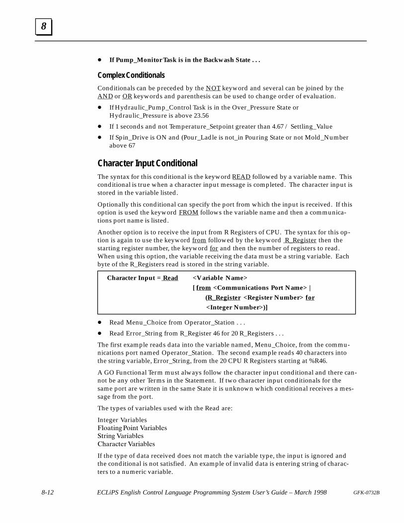
8
8-12 ECLiPS English Control Language Programming System User’s Guide – March 1998 GFK-0732B
� If Pump_Monitor Task is in the Backwash State . . .
Complex Conditionals
Conditionals can be preceded by the NOT keyword and several can be joined by theAND or OR keywords and parenthesis can be used to change order of evaluation.
� If Hydraulic_Pump_Control Task is in the Over_Pressure State orHydraulic_Pressure is above 23.56
� If 1 seconds and not Temperature_Setpoint greater than 4.67 / Settling_Value
� If Spin_Drive is ON and (Pour_Ladle is not_in Pouring State or not Mold_Numberabove 67
Character Input ConditionalThe syntax for this conditional is the keyword READ followed by a variable name. Thisconditional is true when a character input message is completed. The character input isstored in the variable listed.
Optionally this conditional can specify the port from which the input is received. If thisoption is used the keyword FROM follows the variable name and then a communica-tions port name is listed.
Another option is to receive the input from R Registers of CPU. The syntax for this op-tion is again to use the keyword from followed by the keyword R_Register then thestarting register number, the keyword for and then the number of registers to read.When using this option, the variable receiving the data must be a string variable. Eachbyte of the R_Registers read is stored in the string variable.
Character Input = Read <Variable Name>
[ from <Communications Port Name> |
(R_Register <Register Number> for
<Integer Number>)]
� Read Menu_Choice from Operator_Station . . .
� Read Error_String from R_Register 46 for 20 R_Registers . . .
The first example reads data into the variable named, Menu_Choice, from the commu-nications port named Operator_Station. The second example reads 40 characters intothe string variable, Error_String, from the 20 CPU R Registers starting at %R46.
A GO Functional Term must always follow the character input conditional and there can-not be any other Terms in the Statement. If two character input conditionals for thesame port are written in the same State it is unknown which conditional receives a mes-sage from the port.
The types of variables used with the Read are:
Integer Variables����� �� �� �� ��� ����
��� �� ��� ����
������� ��� ����
If the type of data received does not match the variable type, the input is ignored andthe conditional is not satisfied. An example of invalid data is entering string of charac-ters to a numeric variable.

8
8-13GFK-0732B Chapter 8 Referemce
The input is completed and the conditional is true, when an end of message character isreceived at the port. The default end of message character is the carriage return, so thatnormally the input is completed when the <Enter> key is pressed. The end of messagecharacter may be changed by the Set_Commport Functional Expression.
Input to a character variable is complete as soon as one character is received, so that acharacter is stored and the GO executed as soon as any character is received.
IMPORTANT: Character variables cannot be used to receive input through the pro-gramming port when connected to ECLiPS or OnTOP.
Mathematical CalculationsMathematical calculations are used in Functional Terms as in this assignment Term:
Make Pointer_Position = Last_Position * (Forward_Pressure + 345.8)
and in Conditional Terms as in this comparison term:
If Advanced_Magnitude < SIN(Current_Angle) / 45.6 go to Reposition State.
Numerical expressions may be much more complicated, using any of the operators inany order and nested in parenthesis to change order of evaluation or make the expres-sion more readable. Up to 18 levels of parenthesis may be used.
Operator PrecedenceOperators are executed according to the precedence listed in the operator keywordtable. The operators with the lowest precedence number are executed first. Operatorswith the same precedence are executed left to right. Use parenthesis to change the orderof execution.
VariablesVariables are used to store some information in memory. All variables are identified by aunique name that is assigned when the undefined words in the program are defined.Each variable can be configured to save the value over a power cycle or be initializedwhen the program is started. There are two main categories of variables, ASCII andnumeric. Calculations may refer to the value stored in any of the numeric variables.
ASCII VariablesThe ASCII variable types are Character, String and R Register. Character Variables storeone character and use one byte of memory. String Variables store up to 80 characters anduse 80 bytes of memory. String Variables store any ASCII characters. Control charactersare used in the string variable by using the % followed by the # and then two digits thatare the hexadecimal number for the ASCII character, for example:
Make Test_String equals “abc%#1 Bxyz” .
Is an assignment to a String Variable to store the characters abc the escape character andthen xyz.
The R Register Variables can also be used to store character information in the CPU %Rregisters. Use the Write term to send characters to the R Register variables and the Read
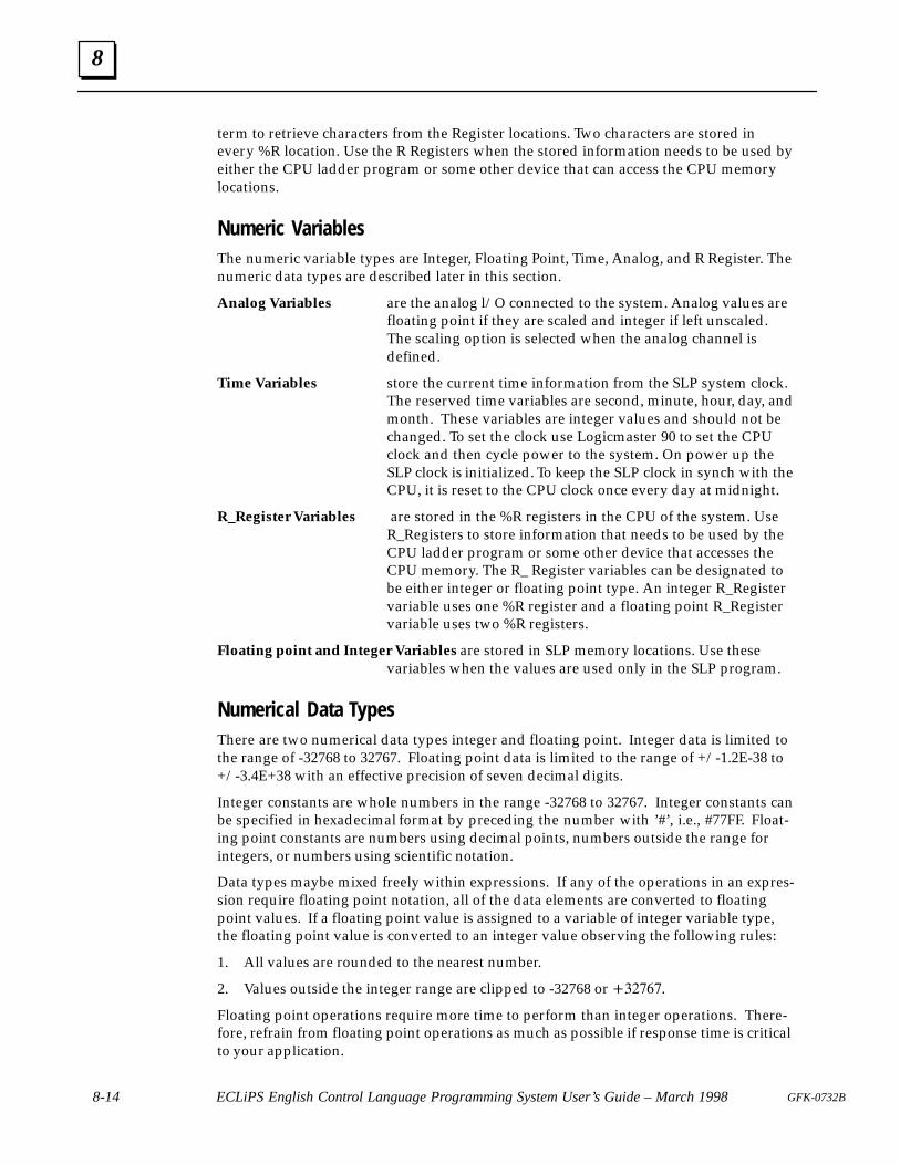
8
8-14 ECLiPS English Control Language Programming System User’s Guide – March 1998 GFK-0732B
term to retrieve characters from the Register locations. Two characters are stored inevery %R location. Use the R Registers when the stored information needs to be used byeither the CPU ladder program or some other device that can access the CPU memorylocations.
Numeric VariablesThe numeric variable types are Integer, Floating Point, Time, Analog, and R Register. Thenumeric data types are described later in this section.
Analog Variables are the analog l/O connected to the system. Analog values are floating point if they are scaled and integer if left unscaled.
The scaling option is selected when the analog channel isdefined.
Time Variables store the current time information from the SLP system clock. The reserved time variables are second, minute, hour, day, andmonth. These variables are integer values and should not bechanged. To set the clock use Logicmaster 90 to set the CPUclock and then cycle power to the system. On power up theSLP clock is initialized. To keep the SLP clock in synch with theCPU, it is reset to the CPU clock once every day at midnight.
R_Register Variables are stored in the %R registers in the CPU of the system. UseR_Registers to store information that needs to be used by theCPU ladder program or some other device that accesses theCPU memory. The R_ Register variables can be designated tobe either integer or floating point type. An integer R_Registervariable uses one %R register and a floating point R_Registervariable uses two %R registers.
Floating point and Integer Variables are stored in SLP memory locations. Use thesevariables when the values are used only in the SLP program.
Numerical Data TypesThere are two numerical data types integer and floating point. Integer data is limited tothe range of -32768 to 32767. Floating point data is limited to the range of +/-1.2E-38 to+/-3.4E+38 with an effective precision of seven decimal digits.
Integer constants are whole numbers in the range -32768 to 32767. Integer constants canbe specified in hexadecimal format by preceding the number with ’#’, i.e., #77FF. Float-ing point constants are numbers using decimal points, numbers outside the range forintegers, or numbers using scientific notation.
Data types maybe mixed freely within expressions. If any of the operations in an expres-sion require floating point notation, all of the data elements are converted to floatingpoint values. If a floating point value is assigned to a variable of integer variable type,the floating point value is converted to an integer value observing the following rules:
1. All values are rounded to the nearest number.
2. Values outside the integer range are clipped to -32768 or �������
Floating point operations require more time to perform than integer operations. There-fore, refrain from floating point operations as much as possible if response time is criticalto your application.
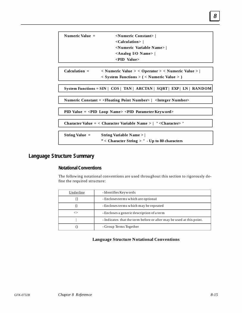
8
8-15GFK-0732B Chapter 8 Referemce
Numeric Value = <Numeric Constant> |
<Calculation> |
<Numeric Variable Name> |
<Analog I/O Name> |
<PID Value>
Calculation = < Numeric Value > < Operator > < Numeric Value > |
< System Functions > ( < Numeric Value > )
System Functions = SIN | COS | TAN | ARCTAN | SQRT | EXP | LN | RANDOM
Numeric Constant = <Floating Point Number> | <Integer Number>
PID Value = <PID Loop Name> <PID Parameter Keyword>
Character Value = < Character Variable Name > | ’ <Character> ’
String Value = String Variable Name > |
” < Character String > ” - Up to 80 characters
Language Structure Summary
Notational Conventions
The following notational conventions are used throughout this section to rigorously de-fine the required structure:
Underline - Identifies Keywords
[] - Encloses terms which are optiona�
{} - Encloses terms which may be repeated
<> - Encloses a generic description of a term
| - Indicates that the term before or after may be used at this point.
() - Group Terms Together
Language Structure Notational Conventions

8
8-16 ECLiPS English Control Language Programming System User’s Guide – March 1998 GFK-0732B
Program Hierarchy
Term Syntax
Program { <Task> }
Task Task: <Task Name> { <State> }
State State: <State Name> [ { <Statement> } ]
Statement ([<Conditional Expression>] <Functional Expression>) ( <Functional Expression> [<Conditional Expression>] )
Functional Structures
Term Syntax
Functional Expression { Functional Term }
Functional Term < Turn On Discretes Term > |<Assign Values Term > |< Change Active States Term > |< Send Serial Information Term > |< PID Control Term > | < Change Serial Port Configuration Term > |< Execute Perform Functions Term >
Turn On Discrete Term Actuate { <Digital I/O Name> |< Internal Flag Name > }
Assign Values Term < Make Term > | < Math-Assignment Term > |< Set_Bit/Clear_Bit Term >_
Make Term Make (< Numeric Assignment Term > |< Character Assignment Term > | <String Assignment Term>)
Numeric Assignment Term ( <Numeric Variable Name> | <Analog I/O Name> )equal < Numeric Value >
Character AssignmentTerm
<Character Variable Name> equal <Character Value>
String Assignment Term <String Variable Name> equal <String Value>
Math-AssignmentTerm < Add Term > |< Subtract Term > | < Multiply Term > | < Divide Term >
Add Term Add ( < Numeric Constant > | < Variable Name> )< Variable Name >
Subtract Term Subtract ( < Numeric Constant > | < Variable Name > ) < Variable Name >
Multiply Term Multiply< Variable Name > ( < Numeric Constant > | < Variable Name > )
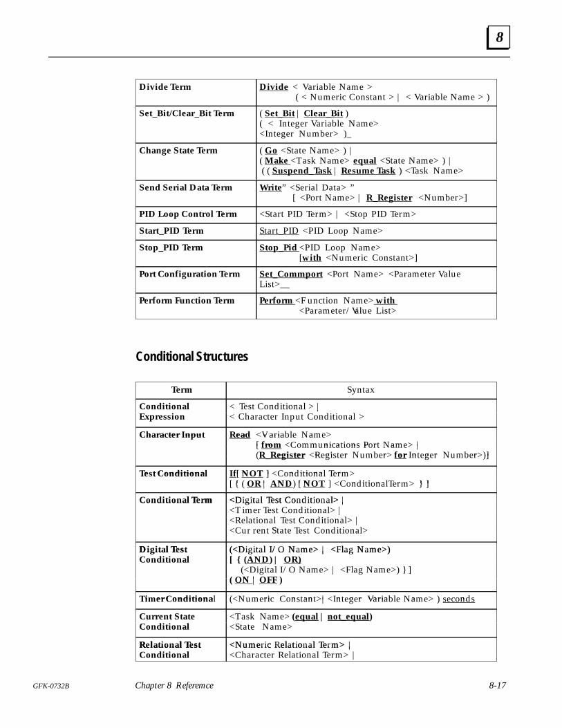
8
8-17GFK-0732B Chapter 8 Referemce
Divide Term Divide < Variable Name > ( < Numeric Constant > | < Variable Name > )
Set_Bit/Clear_Bit Term ( Set_Bit | Clear_Bit )( < Integer Variable Name><Integer Number> )_
Change State Term ( Go <State Name> ) |( Make <Task Name> equal <State Name> ) | ( ( Suspend_Task | Resume Task ) <Task Name>
Send Serial Data Term Write” <Serial Data> ”[ <Port Name> | R_Register <Number>]
PID Loop Control Term <Start PID Term> | <Stop PID Term>
Start_PID Term Start_PID <PID Loop Name>
Stop_PID Term Stop_Pid <PID Loop Name> [with <Numeric Constant>]
Port Configuration Term Set_Commport <Port Name> <Parameter ValueList>__
Perform Function Term Perform <F unction Name> with <Parameter/Value List>
Conditional Structures
Term Syntax
Conditional xpre ion
< Test Conditional > |ara r n n i i na
ConditionaExpression
n i i na |< Character Input Conditional >
Chara ter nput ead Varia aCharacter Input Read <Variable Name>[ ro ni a i n P r a |[ from <Communications Port Name> |
egi ter R gi r r or n g r r ](R_Register <Register Number> for Integer Number>)]
e t Conditiona [ N ] n i i na rTest Conditional If[ NOT ] <Conditional Term>[ { | N [ N ] n i i na r } ][ { ( OR | AND) [ NOT ] <ConditionalTerm> } ]
Conditional Term <Digital Test Conditional> |Conditional Term <Digital Test Conditional> |<T imer Test Conditional> |
R a i na n i i na |i r n i i na |
<Relational Test Conditional> |r r n S a n i i na<Cur rent State Test Conditional>
Digital Test (<Digital I/O Name> | <Flag Name>)Digital Test Conditional
(<Digital I/O Name> | <Flag Name>)[ { (AND) | OR)
igi a O a | F ag a } ]Conditiona N
(<Digital I/O Name> | <Flag Name>) } ]N |( ON | OFF )
i er Conditiona ri n an | n g r Varia a nTimer Conditional (<Numeric Constant>|<Integer Variable Name> ) seconds
Current StateConditiona
<Task Name> (equal | not_equal)S a a
Current tateConditional
a a e ua not e ua<State Name>
Relational Test <Numeric Relational Term> |Relational TestConditional
<Numeric Relational Term> |<Character Relational Term> |
S ring R a i na r
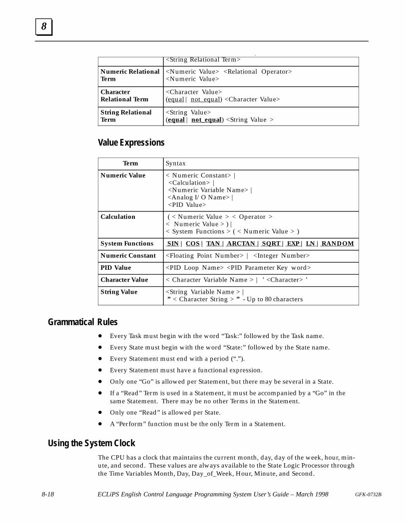
8
8-18 ECLiPS English Control Language Programming System User’s Guide – March 1998 GFK-0732B
Conditiona ara r R a i na r |<String Relational Term>
Numeric Relationaler
<Numeric Value> <Relational Operator>ri Va
Nu eri e ationaTerm
ri Va R a i na O ra r<Numeric Value>
Charactere ationa er
<Character Value>a | n a ara r Va
Chara terRelational Term
ara r Va(equal | not_equal) <Character Value>
String RelationalTerm
<String Value>(equal | not_equal) <String Value >
Value Expressions
Term Syntax
Numeric Value < Numeric Constant> | <Calculation> | <Numeric Variable Name> | <Analog I/O Name> | <PID Value>
Calculation ( < Numeric Value > < Operator >< Numeric Value > ) | < System Functions > ( < Numeric Value > )
System Functions SIN | COS | TAN | ARCTAN | SQRT | EXP | LN | RANDOM
Numeric Constant <Floating Point Number> | <Integer Number>
PID Value <PID Loop Name> <PID Parameter Key word>
Character Value < Character Variable Name > | ’ <Character> ’
String Value <String Variable Name > | ” < Character String > ” - Up to 80 characters
Grammatical Rules� Every Task must begin with the word “Task:” followed by the Task name.
� Every State must begin with the word “State:” followed by the State name.
� Every Statement must end with a period (“ .” ).
� Every Statement must have a functional expression.
� Only one “Go” is allowed per Statement, but there may be several in a State.
� If a “Read” Term is used in a Statement, it must be accompanied by a “Go” in thesame Statement. There may be no other Terms in the Statement.
� Only one “Read” is allowed per State.
� A “Perform” function must be the only Term in a Statement.
Using the System ClockThe CPU has a clock that maintains the current month, day, day of the week, hour, min-ute, and second. These values are always available to the State Logic Processor throughthe Time Variables Month, Day, Day_of_Week, Hour, Minute, and Second.
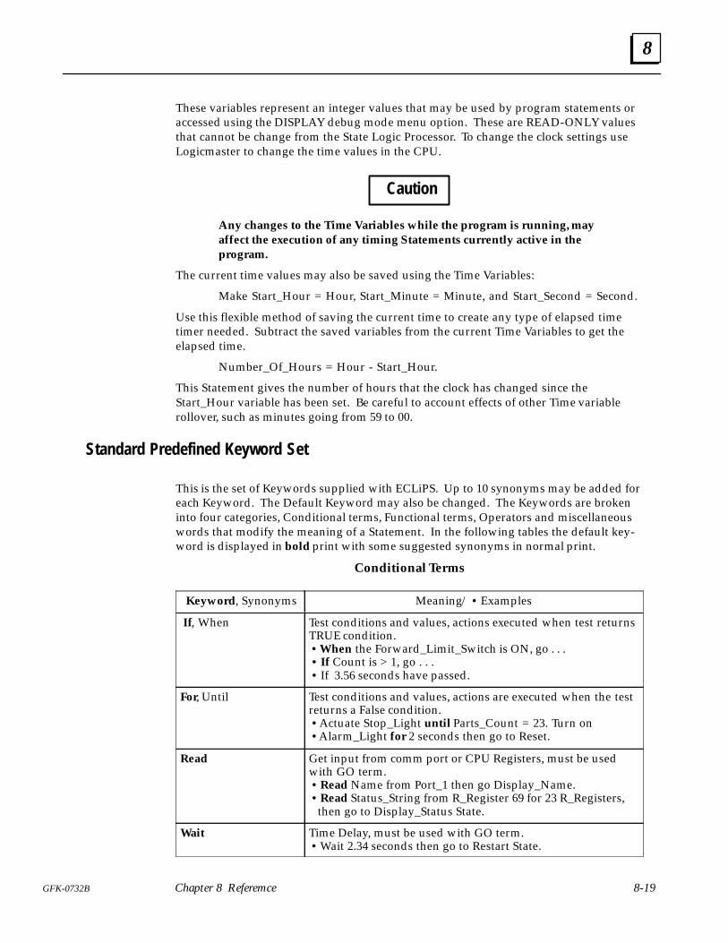
8
8-19GFK-0732B Chapter 8 Referemce
These variables represent an integer values that may be used by program statements oraccessed using the DISPLAY debug mode menu option. These are READ-ONLY valuesthat cannot be change from the State Logic Processor. To change the clock settings useLogicmaster to change the time values in the CPU.
Caution
Any changes to the Time Variables while the program is running, mayaffect the execution of any timing Statements currently active in theprogram.
The current time values may also be saved using the Time Variables:
Make Start_Hour = Hour, Start_Minute = Minute, and Start_Second = Second.
Use this flexible method of saving the current time to create any type of elapsed timetimer needed. Subtract the saved variables from the current Time Variables to get theelapsed time.
Number_Of_Hours = Hour - Start_Hour.
This Statement gives the number of hours that the clock has changed since theStart_Hour variable has been set. Be careful to account effects of other Time variablerollover, such as minutes going from 59 to 00.
Standard Predefined Keyword Set
This is the set of Keywords supplied with ECLiPS. Up to 10 synonyms may be added foreach Keyword. The Default Keyword may also be changed. The Keywords are brokeninto four categories, Conditional terms, Functional terms, Operators and miscellaneouswords that modify the meaning of a Statement. In the following tables the default key-word is displayed in bold print with some suggested synonyms in normal print.
Conditional Terms
Keyword, Synonyms Meaning / • Examples
If, When Test conditions and values, actions executed when test returnsTRUE condition. • When the Forward_Limit_Switch is ON, go . . . • If Count is > 1, go . . .• If 3.56 seconds have passed.
For, Until Test conditions and values, actions are executed when the testreturns a False condition. • Actuate Stop_Light until Parts_Count = 23. Turn on • Alarm_Light for 2 seconds then go to Reset.
Read Get input from comm port or CPU Registers, must be usedwith GO term.• Read Name from Port_1 then go Display_Name.• Read Status_String from R_Register 69 for 23 R_Registers,
then go to Display_Status State.
Wait Time Delay, must be used with GO term. • Wait 2.34 seconds then go to Restart State.
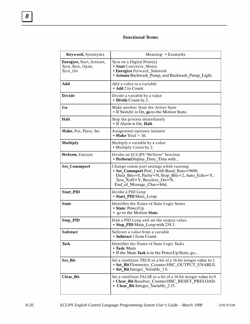
8
8-20 ECLiPS English Control Language Programming System User’s Guide – March 1998 GFK-0732B
Functional Terms
Keyword, Synonyms Meaning / • Examples
Energize, Start, Actuate,Turn, Run, Open,
rn On
Turn on a Digital Point(s)• Start Conveyor_Motor.
nergi e F r ar S n irn R n O n
Turn_Ontart n r r
• Energize Forward_Solenoid. • ��������$&-8$4+#�6/2� $0'�$&-8$4+#�6/2#�,*+5�
Add Add a value to a variable • ��� � 51 �1605�
Divide Divide a variable by a value• �������1605 %9 ��
Go Make another State the Active State• �) �8,5&+� ,4 �0� �� 51 5+(�15,10 �5$5(�
Halt Stop the process immediately• �) �.$3/ ,4 �0� �����
Make, Put, Place, Set Assignment operator initiator• Make Total = 56.
Multiply Multiply a variable by a value • Multiply Count by 2.
Perform, Execute Invoke an ECLiPS “Perform” function• ��������,42.$9#�$5(#�,/(8,5+���
Set_Commport Change comm port settings while running • ����������� �135#� 8,5+ �$6'#�$5(������$5$#�,54��� �$3,59��� �512#�,54����651#�&+1�"�!10#!1))�"� �(&(,7(3#�0����0'#1)#�(44$*(#�+$3�+�'�
Start_PID Invoke a PID Loop • ���������$,0#�112�
State Identifies the Name of State Logic States• ���� �18(3�2• *1 51 5+( �15,10 �����
Stop_PID Halt a PID Loop and set the output value.• ��������$,0#�112 8,5+ �����
Subtract Subtract a value from a variable• � ����� � )31/ �1605�
Task Identifies the Name of State Logic Tasks• ��� �$,0• �) 5+( �$,0 ��� ,4 ,0 5+( �18(3�2�5$5(� *1���
Set_Bit Set a condition TRUE or a bit of a 16 bit integer 7$.6( 51 �• �������.18/(5(3#�1605(3���#������#�������• ������ �05(*(3# $3,$%.(#� ��
Clear_Bit Set a condition FALSE or a bit of a 16 bit integer 7$.6( 51 �• ����������(41.7(3#�1605(3���#�����#��������• ��������� �05(*(3# $3,$%.(#� ��
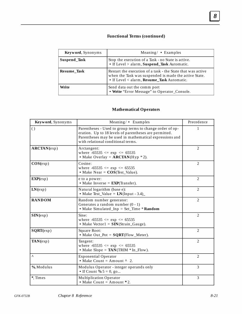
8
8-21GFK-0732B Chapter 8 Referemce
Functional Terms (continued)
Keyword, Synonyms Meaning / • Examples
Suspend_Task Stop the execution of a Task - no State is active.• If Level > alarm, Suspend_Task Automatic.
Resume_Task Restart the execution of a task - the State that was activewhen the Task was suspended is made the active State.• If Level < alarm, Resume_Task Automatic.
Write Send data out the comm port• Write “Error Message” to Operator_Console.
Mathematical Operators
Keyword, Synonyms Meaning / • Examples Precedence
( ) Parentheses - Used to group terms to change order of op-eration. Up to 18 levels of parentheses are permitted.Parentheses may be used in mathematical expressions andwith relational conditional terms.
1
ARCTAN(exp) Arctangent: where -65535 <= exp <= 65535• Make Overlay = ARCTAN(Hyp * 2).
2
COS(exp) Cosine: where -65535 <= exp <= 65535 • Make Near = COS(Test_Value).
2
EXP(exp) e to a power:• Make Inverse = EXP(Transfer).
2
LN(exp) Natural logarithm (base e):• Make Test_Value = LN(Input - 3.4)_
2
RANDOM Random number generator:Generates a random number (0 - 1)• Make Simulated_Inp = Set_Time * Random
2
SIN(exp) Sine:where -65535 <= exp <= 65535 • Make Vector1 = SIN(Strain_Gauge).
2
SQRT(exp) Square Root: • Make Out_Pot = SQRT(Flow_Meter).
2
TAN(exp) Tangent: where -65535 <= exp <= 65535• Make Slope = TAN(TRIM * In_Flow).
2
^ Exponential Operator • Make Count = Amount ^ 2.
2
%, Modulus Modulus Operator - integer operands only• If Count % 5 = 0, go...
3
*, Times Multiplication Operator• Make Count = Amount * 2.
3
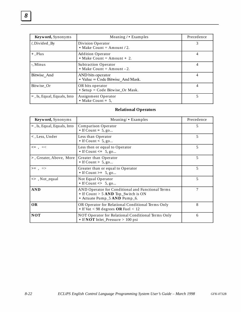
8
8-22 ECLiPS English Control Language Programming System User’s Guide – March 1998 GFK-0732B
Keyword, Synonyms Meaning / • Examples Precedence
/, Divided_By Division Operator• Make Count = Amount / 2.
3
+ , Plus Addition Operator• Make Count = Amount + 2.
4
-, Minus Subtraction Operator• Make Count = Amount - 2.
4
����������� �� ���� ���� ���• � �������� ����������� ���
�
Bitwise_Or OR bits operator • Setup = Code Bitwise_Or Mask.
4
= , Is, Equal, Equals, Into Assignment Operator• Make Count = 5,
5
Relational Operators
Keyword, Synonyms Meaning/ • Examples Precedence
= , Is, Equal, Equals, Into Comparison Operator • If Count = 5, go...
5
< , Less, Under Less than Operator • If Count < 5, go...
5
<= , =< Less then or equal to Operator• If Count <= 5, go...
5
> , Greater, Above, More Greater than Operator• If Count > 5, go...
5
>= , => Greater than or equal to Operator • If Count >= 5, go...
5
<> , Not_equal Not Equal Operator • If Count <> 5, go...
5
AND AND Operator for Conditional and Functional Terms• If Count > 5 AND Top_Switch is ON• Actuate Pump_5 AND Pump_6.
7
OR OR Operator for Relational Conditional Terms Only• If Vat < 98 degrees OR Fuel < 12
8
NOT NOT Operator for Relational Conditional Terms Only• If NOT Inlet_Pressure > 100 psi
6
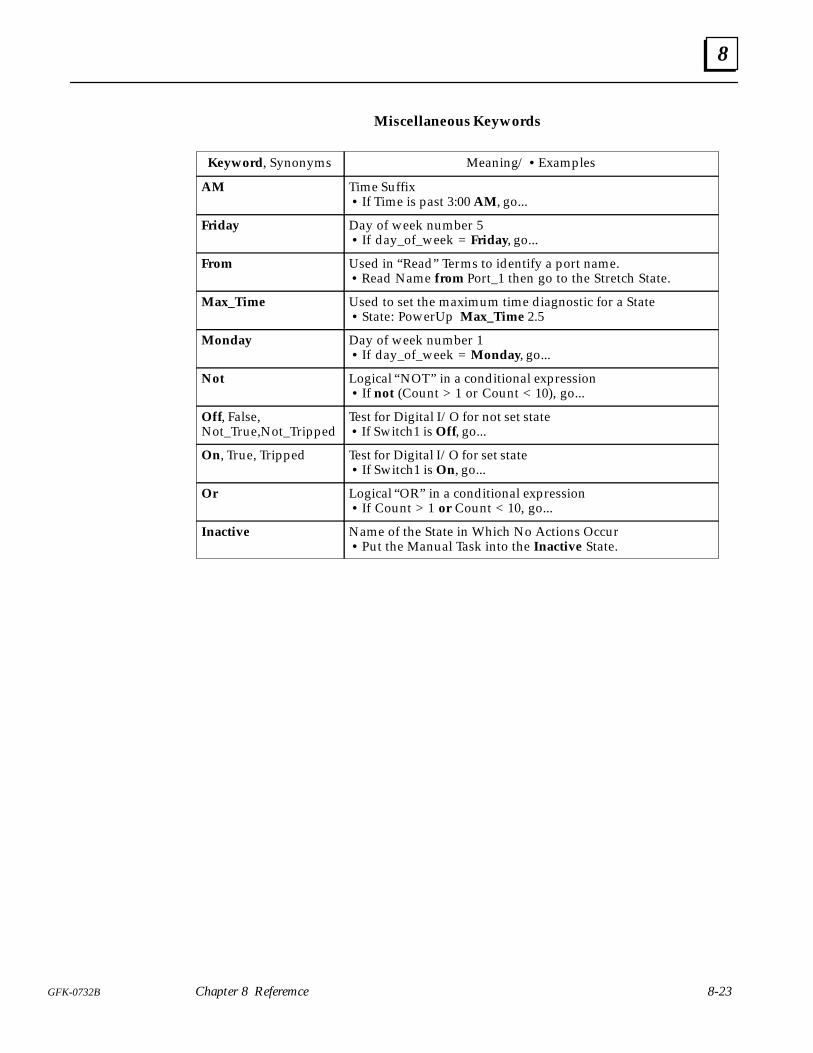
8
8-23GFK-0732B Chapter 8 Referemce
Miscellaneous Keywords
Keyword, Synonyms Meaning / • Examples
AM Time Suffix• If Time is past 3:00 AM, go...
Friday Day of week number 5• If day_of_week = Friday, go...
From Used in “Read” Terms to identify a port name. • Read Name from Port_1 then go to the Stretch State.
Max_Time Used to set the maximum time diagnostic for a State• State: PowerUp Max_Time 2.5
Monday Day of week number 1• If day_of_week = Monday, go...
Not Logical “NOT” in a conditional expression• If not (Count > 1 or Count < 10), go...
Off, False,Not_True,Not_Tripped
Test for Digital I/O for not set state • If Switch1 is Off, go...
On, True, Tripped Test for Digital I/O for set state• If Switch1 is On, go...
Or Logical “OR” in a conditional expression• If Count > 1 or Count < 10, go...
Inactive Name of the State in Which No Actions Occur • Put the Manual Task into the Inactive State.
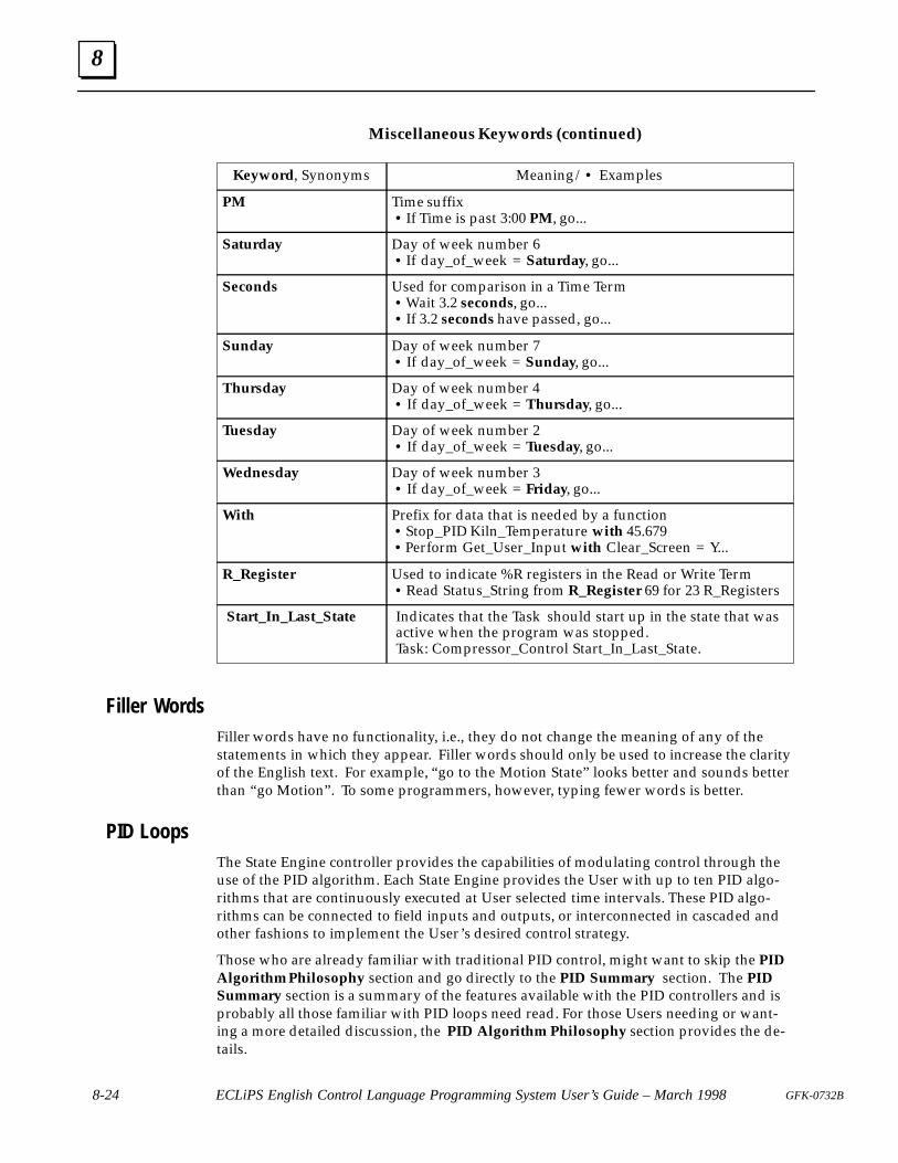
8
8-24 ECLiPS English Control Language Programming System User’s Guide – March 1998 GFK-0732B
Miscellaneous Keywords (continued)
Keyword, Synonyms Meaning / • Examples
PM Time suffix• If Time is past 3:00 PM, go...
Saturday Day of week number 6• If day_of_week = Saturday, go...
Seconds Used for comparison in a Time Term• Wait 3.2 seconds, go...• If 3.2 seconds have passed, go...
Sunday Day of week number 7 • If day_of_week = Sunday, go...
Thursday Day of week number 4 • If day_of_week = Thursday, go...
Tuesday Day of week number 2• If day_of_week = Tuesday, go...
Wednesday Day of week number 3• If day_of_week = Friday, go...
With Prefix for data that is needed by a function • Stop_PID Kiln_Temperature with 45.679 • Perform Get_User_Input with Clear_Screen = Y...
R_Register Used to indicate %R registers in the Read or Write Term• Read Status_String from R_Register 69 for 23 R_Registers
Start_In_Last_State Indicates that the Task should start up in the state that wasactive when the program was stopped.Task: Compressor_Control Start_In_Last_State.
Filler WordsFiller words have no functionality, i.e., they do not change the meaning of any of thestatements in which they appear. Filler words should only be used to increase the clarityof the English text. For example, “go to the Motion State” looks better and sounds betterthan “go Motion” . To some programmers, however, typing fewer words is better.
PID LoopsThe State Engine controller provides the capabilities of modulating control through theuse of the PID algorithm. Each State Engine provides the User with up to ten PID algo-rithms that are continuously executed at User selected time intervals. These PID algo-rithms can be connected to field inputs and outputs, or interconnected in cascaded andother fashions to implement the User’s desired control strategy.
Those who are already familiar with traditional PID control, might want to skip the PIDAlgorithm Philosophy section and go directly to the PID Summary section. The PIDSummary section is a summary of the features available with the PID controllers and isprobably all those familiar with PID loops need read. For those Users needing or want-ing a more detailed discussion, the PID Algorithm Philosophy section provides the de-tails.
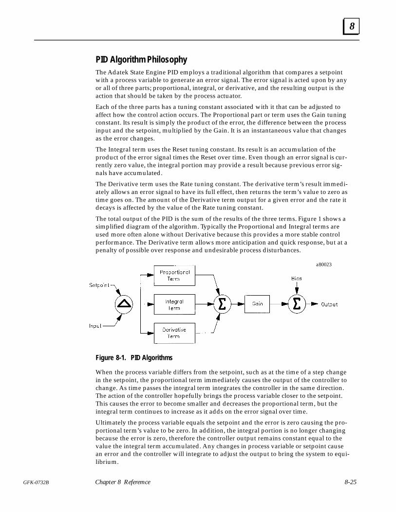
8
8-25GFK-0732B Chapter 8 Referemce
PID Algorithm PhilosophyThe Adatek State Engine PID employs a traditional algorithm that compares a setpointwith a process variable to generate an error signal. The error signal is acted upon by anyor all of three parts; proportional, integral, or derivative, and the resulting output is theaction that should be taken by the process actuator.
Each of the three parts has a tuning constant associated with it that can be adjusted toaffect how the control action occurs. The Proportional part or term uses the Gain tuningconstant. Its result is simply the product of the error, the difference between the processinput and the setpoint, multiplied by the Gain. It is an instantaneous value that changesas the error changes.
The Integral term uses the Reset tuning constant. Its result is an accumulation of theproduct of the error signal times the Reset over time. Even though an error signal is cur-rently zero value, the integral portion may provide a result because previous error sig-nals have accumulated.
The Derivative term uses the Rate tuning constant. The derivative term’s result immedi-ately allows an error signal to have its full effect, then returns the term’s value to zero astime goes on. The amount of the Derivative term output for a given error and the rate itdecays is affected by the value of the Rate tuning constant.
The total output of the PID is the sum of the results of the three terms. Figure 1 shows asimplified diagram of the algorithm. Typically the Proportional and Integral terms areused more often alone without Derivative because this provides a more stable controlperformance. The Derivative term allows more anticipation and quick response, but at apenalty of possible over response and undesirable process disturbances.
a80023
Figure 8-1. PID Algorithms
When the process variable differs from the setpoint, such as at the time of a step changein the setpoint, the proportional term immediately causes the output of the controller tochange. As time passes the integral term integrates the controller in the same direction.The action of the controller hopefully brings the process variable closer to the setpoint.This causes the error to become smaller and decreases the proportional term, but theintegral term continues to increase as it adds on the error signal over time.
Ultimately the process variable equals the setpoint and the error is zero causing the pro-portional term’s value to be zero. In addition, the integral portion is no longer changingbecause the error is zero, therefore the controller output remains constant equal to thevalue the integral term accumulated. Any changes in process variable or setpoint causean error and the controller will integrate to adjust the output to bring the system to equi-librium.
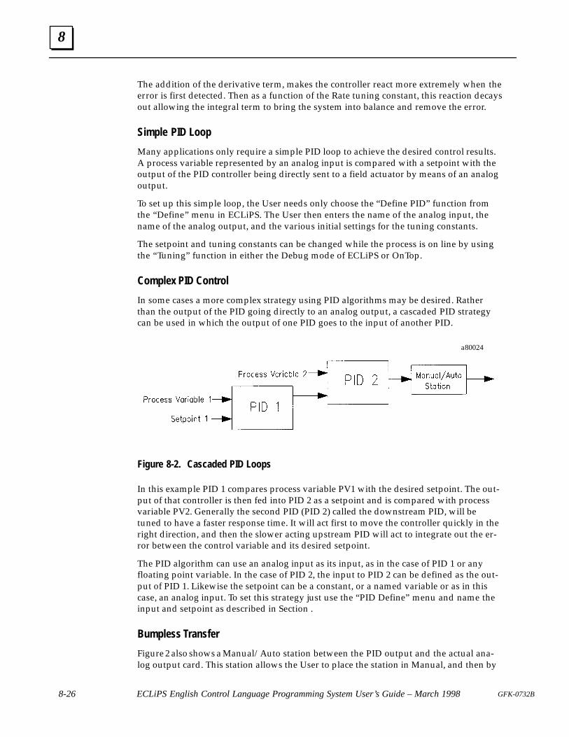
8
8-26 ECLiPS English Control Language Programming System User’s Guide – March 1998 GFK-0732B
The addition of the derivative term, makes the controller react more extremely when theerror is first detected. Then as a function of the Rate tuning constant, this reaction decaysout allowing the integral term to bring the system into balance and remove the error.
Simple PID Loop
Many applications only require a simple PID loop to achieve the desired control results.A process variable represented by an analog input is compared with a setpoint with theoutput of the PID controller being directly sent to a field actuator by means of an analogoutput.
To set up this simple loop, the User needs only choose the “Define PID” function fromthe “Define” menu in ECLiPS. The User then enters the name of the analog input, thename of the analog output, and the various initial settings for the tuning constants.
The setpoint and tuning constants can be changed while the process is on line by usingthe “Tuning” function in either the Debug mode of ECLiPS or OnTop.
Complex PID Control
In some cases a more complex strategy using PID algorithms may be desired. Ratherthan the output of the PID going directly to an analog output, a cascaded PID strategycan be used in which the output of one PID goes to the input of another PID.
a80024
Figure 8-2. Cascaded PID Loops
In this example PID 1 compares process variable PV1 with the desired setpoint. The out-put of that controller is then fed into PID 2 as a setpoint and is compared with processvariable PV2. Generally the second PID (PID 2) called the downstream PID, will betuned to have a faster response time. It will act first to move the controller quickly in theright direction, and then the slower acting upstream PID will act to integrate out the er-ror between the control variable and its desired setpoint.
The PID algorithm can use an analog input as its input, as in the case of PID 1 or anyfloating point variable. In the case of PID 2, the input to PID 2 can be defined as the out-put of PID 1. Likewise the setpoint can be a constant, or a named variable or as in thiscase, an analog input. To set this strategy just use the “PID Define” menu and name theinput and setpoint as described in Section .
Bumpless Transfer
Figure 2 also shows a Manual/Auto station between the PID output and the actual ana-log output card. This station allows the User to place the station in Manual, and then by

8
8-27GFK-0732B Chapter 8 Referemce
means of Raise and Lower pushbuttons, change the actual value of the Manual/Autooutput. In the Auto mode, the value of the Manual/Auto station is equal to the output ofthe PID.
When the M/A station is in Manual, the station value can and usually will be forced to avalue other than one that will make the setpoint equal the process variable input. If thePID followed its normal operation, the integral term would continue to integrate be-cause of the error signal between the process variable and setpoint. This would leave adifference between the PID output, which is the Auto input to the M/A station, and theactual M/A output. Then when Auto mode is selected, this difference would cause ajump or bump in the M/A output. This would upset the process and is desirable to avoid.
To prevent this bump from happening, the PID needs to have another mode of opera-tion besides its automatic mode. In this mode, called tracking, the PID output will bemaintained at what ever value it is set to, such as the M/A output in this example. ThePID will not perform its normal arithmetic, but will instead set itself so that when track-ing is removed, the PID output gradually goes to the proper value and avoids the bump.This is called bumpless transfer.
Each of the ten PID algorithms have logical signals associated with them that use thename Track_Mode and the actual PID name. As an example, if the User named the firstPID algorithm Tank_Level then the logical signal would be called Tank_LevelTrack_Mode. When Track_Mode is made true, then the PID automatically discontinuesits normal algorithm, and begins tracking its output and preparing for bumpless transfer.
The User can set the Track_Mode variable from any active State. Using this variable, theUser can create any tracking strategy he desires.
Anti-Reset Windup
Using a cascaded PID strategy can cause the User some subtle problems. In the exampleshown in Figure 2, if PID 2 has reached its maximum and PID 1 still has an error signalbecause the setpoint does not equal PV1, then PID 1 would continue to integrate. Theoutput of PID 1 would continue to increase, but it would have no affect on PID 2 since itis already at its maximum. However when the error signal of PID 1 reversed directionand caused PID 1 to begin integrating in the opposite direction, PID 1 would have to in-tegrate below the threshold value it was when PID 2 reached its maximum before itwould have any affect on PID 2. This excess amount of output PID 1 has accumulated iscommonly referred to as reset windup.
The upstream controller, PID 1, needs to be prevented from winding up. An input calledBlock_Up will transfer the PID algorithm into a mode such that it will not integrate inthe Up, towards 100%, direction. This is called anti-reset windup.
The PID will still be able to integrate down if the error signal reverses direction. That is,if the process variable is less than the setpoint the PID will not integrate up. If the pro-cess variable becomes greater than the setpoint the PID will integrate down. TheBlock_Down input works exactly opposite.
In the case of Figure 2, if the setpoint for PID 1 is greater than PV1, PID 1 output willcontinually increase. This is the setpoint for PID 2 and assume it is already greater thanPV2 and PID 2 has reached its high limit. There is no profit in PID 1 output getting largersince PID 2 can not respond to its demand, PID 2 is already at its limit. Therefore theUser should set the PID_1 Block_Up input true and stop the PID from winding up fur-ther.
8
8-28 ECLiPS English Control Language Programming System User’s Guide – March 1998 GFK-0732B
Then when either PV2 increases or the high limit on PID 2 is changed which will allowfurther action by PID 2, the PID_1 Block_Up input can be set false and PID 1 can resumeintegrating. Or if PV1 rises above the setpoint in response to the control action, PID 1will begin integrating the output of PID 1 in the lower direction which is permissible.When PID 1 output falls below the input PV2 into the downstream PID 2, PID 2 willintegrate down below its high limit and remove PID_1 Block_Up and return the com-plete loop to normal.
Using the Block_Up and Block_Down inputs any amount of cascading of PIDs can beaccomplished without reset windup occurring and with bumpless transfers from onemode to another.
Tuning and Scaling
The Gain, Reset, and Rate constants can be adjusted to obtain the desired PID perfor-mance, such as speed of response and over shoot. In addition, each PID has a high limitand low limit that can be set to limit the output to less than its full range when desired.These limits automatically employ anti-reset windup.
Within the PID algorithm, all signals are treated as being 0 to 100%. Each input and theoutput and the high low limits, have scaling constants associated with them. Values giv-en for this parameter are converted to a percentage of the range specified by the scalingconstants.
If these constants are left blank at programming time, that input is assumed to be al-ready 0 to 100%. Values given for this parameter are assumed to be a percentage whichhas already been scaled.
By using the scaling factors, the output can be scaled to have a live 0, that is go from-100% to +100%. This is a valuable tool at times when cascading PIDs and the upstreamPID needs the ability to overcome and move the downstream PID across its full range.
PID SummaryThe Adatek state engine provides up to ten PID algorithms. Each algorithm is identicaland can be executed at User selected time intervals with the minimum interval being 1second. The PID algorithms can each be independent or can be cascaded together withthe output of one PID becoming the input to another. Each PID features built in bump-less transfer and anti-reset windup features.
Each PID is initialized in the Program mode of ECLiPS using either the LIST or DEFINEoption from the program mode menu. PID Loops are tuned on-line in the Debug modeor using OnTOP. Each PID loop is given an alpha numeric name which can be up totwenty characters in length. All references to the PID loop use this name.
To start a PID Loop use the Start_PID keyword. For example the statement:
Start_PID Tank_Level.
starts the PID Loop name Tank_Level.
To stop a PID Loop use the Stop_PID keyword. For example the Statement:
Stop_PID Tank_Level with 10.
stops the PID Loop named Tank_Level and sets the output to 10.
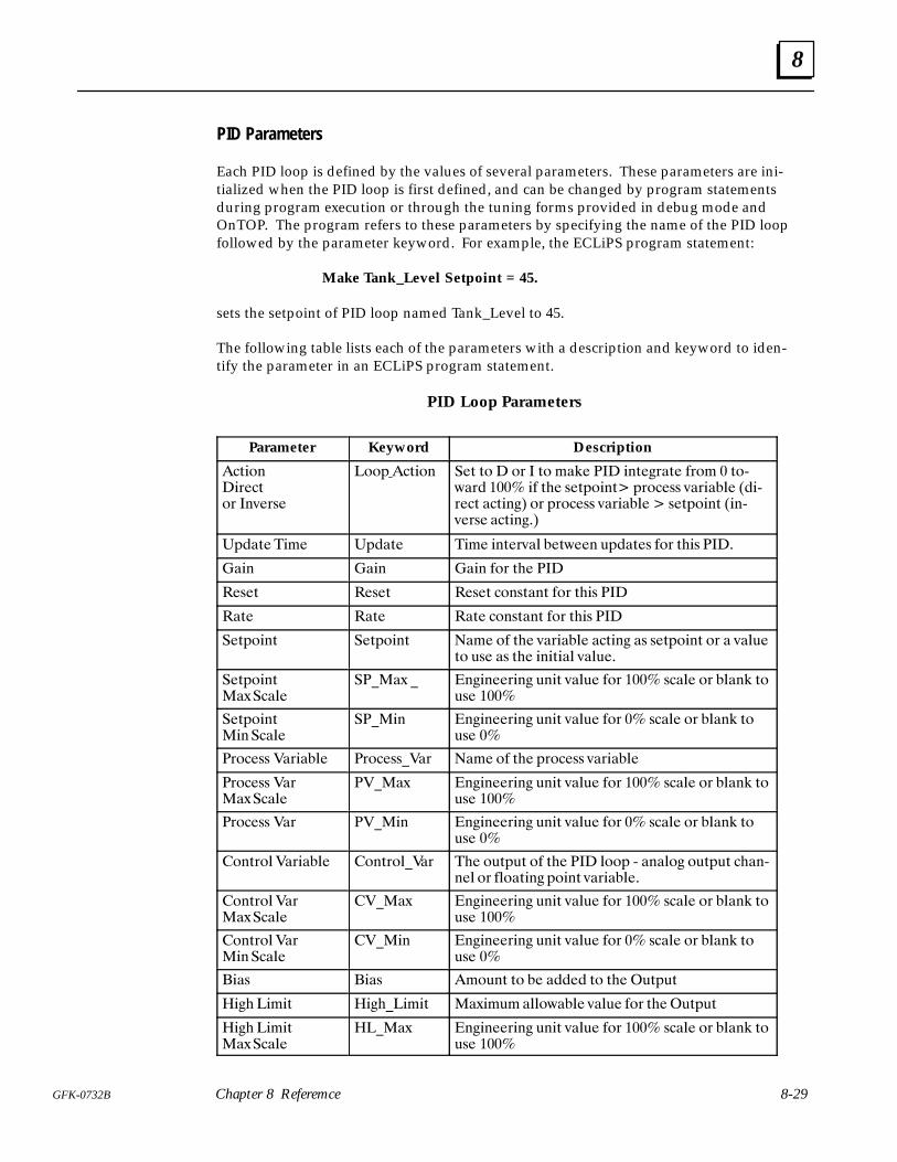
8
8-29GFK-0732B Chapter 8 Referemce
PID Parameters
Each PID loop is defined by the values of several parameters. These parameters are ini-tialized when the PID loop is first defined, and can be changed by program statementsduring program execution or through the tuning forms provided in debug mode andOnTOP. The program refers to these parameters by specifying the name of the PID loopfollowed by the parameter keyword. For example, the ECLiPS program statement:
Make Tank_Level Setpoint = 45.
sets the setpoint of PID loop named Tank_Level to 45.
The following table lists each of the parameters with a description and keyword to iden-tify the parameter in an ECLiPS program statement.
PID Loop Parameters
Parameter Keyword Description
�-$)(�$+ �-)+ �(/ +,
�))* �-$)( � - -) � )+ � -) '�% ��� $(- "+�- !+)' � -)20�+� ���� $! -# , -*)$(-� *+)� ,, /�+$��& ��$2+ �- ��-$("� )+ *+)� ,, /�+$��& � , -*)$(- �$(2/ +, ��-$("��
�*��- �$' �*��- �$' $(- +/�& � -0 ( .*��- , !)+ -#$, ����
��$( ��$( ��$( !)+ -# ���
� , - � , - � , - �)(,-�(- !)+ -#$, ���
��- ��- ��- �)(,-�(- !)+ -#$, ���
� -*)$(- � -*)$(- ��' )! -# /�+$��& ��-$(" �, , -*)$(- )+ � /�&. -) ., �, -# $($-$�& /�&. �
� -*)$(-��1���&
�����1 � ("$( +$(" .($- /�&. !)+ ���� ,��& )+ �&�(% -)., ����
� -*)$(-�$(���&
����$( ("$( +$(" .($- /�&. !)+ �� ,��& )+ �&�(% -)., ��
�+)� ,, ��+$��& �+)� ,,���+ ��' )! -# *+)� ,, /�+$��&
�+)� ,, ��+��1���&
�����1 ("$( +$(" .($- /�&. !)+ ���� ,��& )+ �&�(% -)., ����
�+)� ,, ��+ ����$( ("$( +$(" .($- /�&. !)+ �� ,��& )+ �&�(% -)., ��
�)(-+)&��+$��& �)(-+)&���+ �# ).-*.- )! -# ��� &))* 2 �(�&)" ).-*.- �#�(2( & )+ !&)�-$(" *)$(- /�+$��& �
�)(-+)&��+��1���&
�����1 ("$( +$(" .($- /�&. !)+ ���� ,��& )+ �&�(% -)., ����
�)(-+)&��+�$(���&
����$( ("$( +$(" .($- /�&. !)+ �� ,��& )+ �&�(% -)., ��
$�, $�, ').(- -) � ��� � -) -# �.-*.-
�$"# �$'$- �$"#��$'$- ��1$'.' �&&)0��& /�&. !)+ -# �.-*.-
�$"# �$'$-��1���&
�����1 ("$( +$(" .($- /�&. !)+ ���� ,��& )+ �&�(% -)., ����
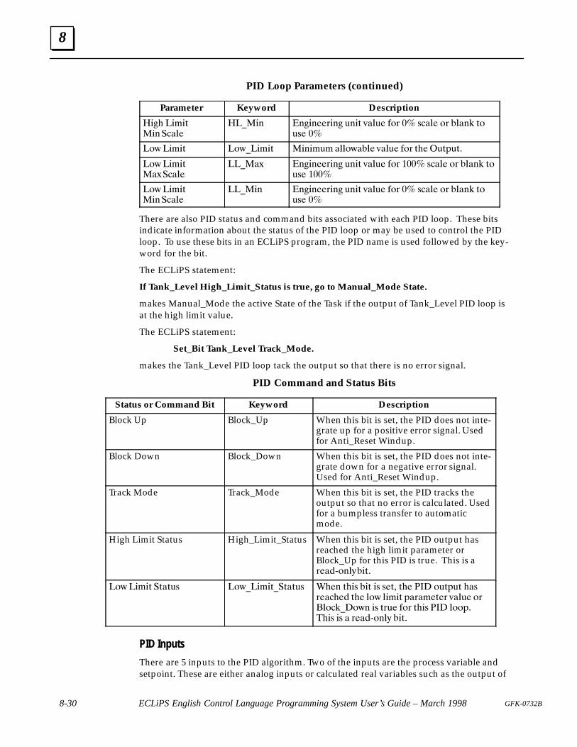
8
8-30 ECLiPS English Control Language Programming System User’s Guide – March 1998 GFK-0732B
PID Loop Parameters (continued)
Parameter Keyword Description
��� ����% � �����
�� � �� ��#� � & �% '��&� �!# �� $���� !# ��� � %!&$� ��
�!(����% �!(�����% � ��&� ���!(���� '��&� �!# %���&%"&%�
�!(����% �)�����
��� �) �� ��#� � & �% '��&� �!# ���� $���� !# ��� � %!&$� ����
�!(����% � �����
��� � �� ��#� � & �% '��&� �!# �� $���� !# ��� � %!&$� ��
There are also PID status and command bits associated with each PID loop. These bitsindicate information about the status of the PID loop or may be used to control the PIDloop. To use these bits in an ECLiPS program, the PID name is used followed by the key-word for the bit.
The ECLiPS statement:
If Tank_Level High_Limit_Status is true, go to Manual_Mode State.
makes Manual_Mode the active State of the Task if the output of Tank_Level PID loop isat the high limit value.
The ECLiPS statement:
Set_Bit Tank_Level Track_Mode.
makes the Tank_Level PID loop tack the output so that there is no error signal.
PID Command and Status Bits
Status or Command Bit Keyword Description
Block Up Block_Up When this bit is set, the PID does not inte-grate up for a positive error signal. Usedfor Anti_Reset Windup.
Block Down Block_Down When this bit is set, the PID does not inte-grate down for a negative error signal.Used for Anti_Reset Windup.
Track Mode Track_Mode When this bit is set, the PID tracks theoutput so that no error is calculated. Usedfor a bumpless transfer to automaticmode.
High Limit Status High_Limit_Status When this bit is set, the PID output hasreached the high limit parameter orBlock_Up for this PID is true. This is a#���+! �*��%�
�!( ����% �%�%&$ �!(�����%��%�%&$ ��� %��$ ��% �$ $�%� %�� ��� !&%"&% ��$#������ %�� �!( ����% "�#���%�# '��&� !#��!����!( �$ %#&� �!# %��$ ��� �!!"����$ �$ � #���+! �* ��%�
PID Inputs
There are 5 inputs to the PID algorithm. Two of the inputs are the process variable andsetpoint. These are either analog inputs or calculated real variables such as the output of

8
8-31GFK-0732B Chapter 8 Referemce
another PID. The setpoint can also be a constant which can be adjusted on line from thePID tuning menu available in OnTOP or the ECLiPS Debug Mode.
The two analog inputs, process variable and setpoint, are treated as 0 to 100% signalsinside the algorithm for mathematical purposes. Each input and output has a maximumand minimum scale parameter associated with it. When the User programs the PID, hesets the minimum engineering unit which will correspond to 0% and the maximum en-gineering unit that will correspond to 100% for that input. The PID algorithm will inter-nally scale the inputs, generating a percentage of the scaling range before they are used.If the minimum and maximum scale parameters are left blank, the algorithm assumesthat input is a percentage already scaled 0 to 100%.
The other three inputs are digital values and can be used to implement complex controlstrategies. They can be actuated by any active State of a Task. They have been assignednames based upon the PID Loop with which they are associated. These names areTrack_Mode, Block_Up and Block_Down. These inputs are controlled with the Set_Bitand Clear_Bit keywords.
If a PID Loop is named Tank_Level then the ECLiPS program statement:
Set_Bit Tank_Level Track_Mode.
puts PID loop Tank_Level into tracking mode.
The Track_Mode input when set, puts the PID loop into a track mode where the outputis not changed by the PID, and the algorithm is set up to perform a bumpless transferwhen the Track_Mode input goes back to being false. This signal would be used with aManual/Automatic station to obtain Manual/Auto bumpless transfer.
The other two inputs, PID_Block_Up and PID_Block_Down limit the PID loop to inte-grating in only one direction and tracking in the other direction. For example, whenBlock_Up is true, the PID is allowed to integrate down, towards zero, when the errorsignal, the difference between setpoint and process variable, is negative. If the error sig-nal is positive however, the output will not change and the integral portion will not beallowed to wind up. Block_Down works exactly opposite.
These two inputs can be used to provide Anti-Reset Windup when one PID is cascadedinto another PID. If during the course of operation the down stream PID reaches thepoint it can no longer integrate in response to the upstream PIDs output, as when itreaches full scale, then any further integrating of the upstream PID would be counterproductive. These inputs can stop that excess integration in the counter productive direc-tion while allowing immediate response in the opposite direction which is the directionthat will have an affect on the down stream PID.
Using the Track, Block_Up and Block_Down signals allow the User to build very sophis-ticated controls. If all that is needed is a simple single loop controller, these inputs can beignored. A more detailed discussion of these inputs and their use is in the PID Algo-rithm Philosophy Section.
PID Output
The PID outputs consist of a floating point value output that can either be assigned di-rectly to an analog output, or to a floating point variable for use such as the input toanother PID or in some calculation. Internal to the PID, the output’s range is 0 to 100%.Like the inputs, the output also has a scaling constant that allows the User to set themaximum and minimum scale. This allows the User to make the output be a -100% to

8
8-32 ECLiPS English Control Language Programming System User’s Guide – March 1998 GFK-0732B
+100% controller, or any other engineering units desired. If the maximum and mini-mum scale constants are left blank, the PID output is 0 to 100%.
The other three outputs are digital variables that indicate the status of the PID algorithm.They are Track_Mode, HL_Status and LL_Status. The two limit outputs are true wheneither the PID has reached its limit or the Block_Up or Block_Down inputs are true.
The outputs may be used in the ECLiPS program by specifying the PID name followedby the appropriate keyword. For example, the ECLiPS program statement:
If Tank_Level LL_Status is true, go to the Reset State.
makes Reset the active State of this task.
Tuning Constants
The PID algorithm also has several adjustable tuning constants. These include the Gain,Reset and Rate, the high limit and low limit, and a bias value. The bias is a value that isadded to the output at all times and can be used to insure a minimum output from thePID.
The high and low limits set maximum and minimum values, within the scale maximumand minimum, that the controller output will not exceed. When these limits are reached,the appropriate status output is set, and anti-reset windup techniques automatically gointo affect for that PID.
Every PID also can be selected to be either a direct acting or inverse acting controller.This is a parameter selected at programming time. A direct acting controller will inte-grate from 0 to 100% if the setpoint is greater than the process variable. A reverse actingcontroller will integrate from 0 to 100% when the process variable is greater than thesetpoint. All other features are exactly the same whether the PID is in the direct or in-verse mode.
The following is a summary of User selected values. These values are all entered in thePID Loop Configuration form displayed for initializing a PID loop. PID loops are initial-ized in program mode using the LIST and DEFINE options from the program modemenu.
Perform FunctionsThe Perform functions implement operations which are more complicated than the com-mon State Language Terms. ECLiPS presents a form which has a template of informa-tion that is entered by the programmer. When this form is completed ECLiPS enters theEnglish text for the proper execution of the function.
The State where a Perform function appears should usually be structured so that thePerform is executed for only one scan. A common error in using Performs, is that theprogram is structured such that the Perform is executed several times, i,e., each time theState is scanned.
Perform functions are Functional Terms and must be the only Terms in the Statement.
Perform Function FormsECLiPS presents a form to enter the parameters for the Perform functions. Except for thespecialized Perform functions described in the next section, most of the forms are tables

8
8-33GFK-0732B Chapter 8 Referemce
providing information about each of the parameters. The column headings of the tablefollow:
Parameter Name Type Use Required Actual
Parameter Name identifies the parameter describe in this row of the table.
Type specifies the parameter data type and may be integer, floating point,character, string, digital, or any type.
Use Specifies whether a variable, constant, or both may be used for thisparameter.
Required Specifies whether this parameter is required in the function call.The parameters that are not required are at the end of theparameter list. No parameters may be entered following one thathas not been used.
Actual This is where the variable or constant for the parameter is enteredfor this particular function call.
Table FunctionsThe set of table functions (individual descriptions to follow) allow the User to performseveral functions using data in a table or array type fashion.
Tables in General
All of these functions work on the same tables or arrays of data. A Table is a two dimen-sional array of values that can be either floating point numbers (float), integer numbers(integer), sequence of characters (string) or binary numbers (digital I/O status). Everyelement of that table must be of the same type and when the Table is defined the type ofvariable is established.
There can be a maximum number of 100 Tables, each assigned a unique number from 1to 100. These tables can be of any size determined by the number of rows and columnsassigned to them until the maximum amount of memory allocated for Table use is con-sumed. There is 20K bytes of memory reserved for use with table functions.
A Table must first be defined before it can be used. This is done using the four Table De-fine functions. The Swap_Table_Value functions named Swap_Table_Value_Int,Swap_Table_Value_Float, Swap_Table_Value_Dig, and Swap_Table_Str allow the User toeither write a value from a variable of the same type into a Table element, or read a valuefrom a Table element into a variable of the same type.
The Init_Table functions named Init_Table_Integer, Init_Table_Float, and Init_Table_Digi-tal allow the user to store multiple values into a Table at one time. There is no initializa-tion function for a string table. The Copy_Table_To_Table function allows the User tocopy one Table’s value into another Table.
All Table functions check to make certain that when a Table is selected for use, it fits thedefinition that has been previously creates. Thus a Swap_Value to a Table defined as in-teger must have an integer variable, or both Tables selected in a Copy_Table_To_Tablemust be of the same type, or a Swap_Value cannot refer to a row number for a table thatis greater than the total number of rows defined for that Table.
In the event of misuse of the functions being detected either ECLiPS will produce an er-ror at download time or (and this is most likely) an error message will be generated atrun time.
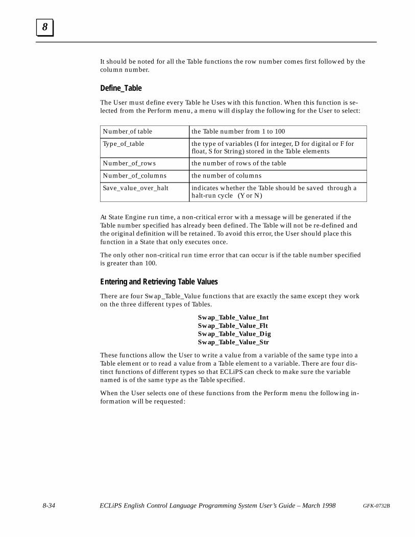
8
8-34 ECLiPS English Control Language Programming System User’s Guide – March 1998 GFK-0732B
It should be noted for all the Table functions the row number comes first followed by thecolumn number.
Define_Table
The User must define every Table he Uses with this function. When this function is se-lected from the Perform menu, a menu will display the following for the User to select:
Number of table the Table number from 1 to 100
Type_of_table the type of variables (I for integer, D for digital or F forfloat, S for String) stored in the Table elements
Number_of_rows the number of rows of the table
Number_of_columns the number of columns
Save_value_over_halt indicates whether the Table should be saved through ahalt-run cycle (Y or N)
At State Engine run time, a non-critical error with a message will be generated if theTable number specified has already been defined. The Table will not be re-defined andthe original definition will be retained. To avoid this error, the User should place thisfunction in a State that only executes once.
The only other non-critical run time error that can occur is if the table number specifiedis greater than 100.
Entering and Retrieving Table Values
There are four Swap_Table_Value functions that are exactly the same except they workon the three different types of Tables.
Swap_Table_Value_IntSwap_Table_Value_FltSwap_Table_Value_DigSwap_Table_Value_Str
These functions allow the User to write a value from a variable of the same type into aTable element or to read a value from a Table element to a variable. There are four dis-tinct functions of different types so that ECLiPS can check to make sure the variablenamed is of the same type as the Table specified.
When the User selects one of these functions from the Perform menu the following in-formation will be requested:
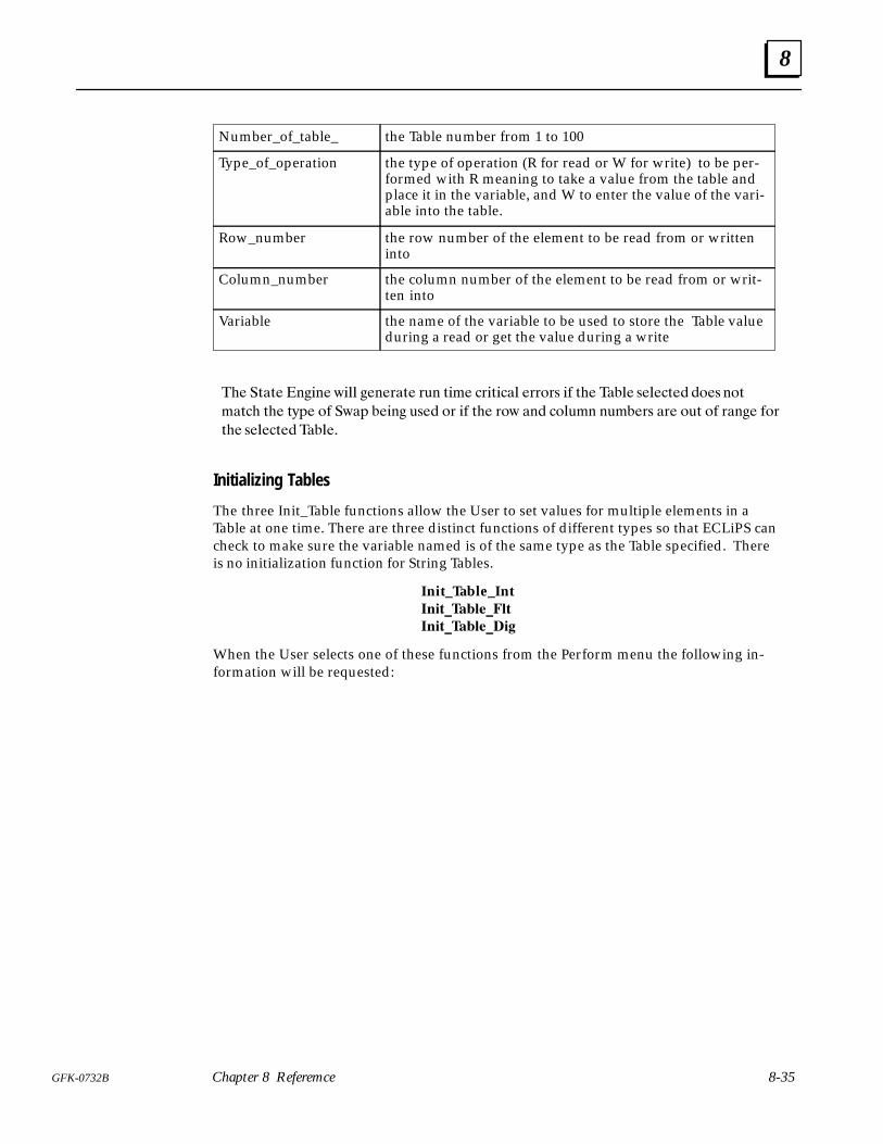
8
8-35GFK-0732B Chapter 8 Referemce
Number_of_table_ the Table number from 1 to 100
Type_of_operation the type of operation (R for read or W for write) to be per-formed with R meaning to take a value from the table andplace it in the variable, and W to enter the value of the vari-able into the table.
Row_number the row number of the element to be read from or writteninto
Column_number the column number of the element to be read from or writ-ten into
Variable the name of the variable to be used to store the Table valueduring a read or get the value during a write
� ���� ����� ���� ����� ��� ��� �������� ����� �� � ���� ���� �� ���
���� � ��� �� ���� ���� �� �� �� � ��� �� ������ ������ �� ��� �� ���� ���
� ���� �����
Initializing Tables
The three Init_Table functions allow the User to set values for multiple elements in aTable at one time. There are three distinct functions of different types so that ECLiPS cancheck to make sure the variable named is of the same type as the Table specified. Thereis no initialization function for String Tables.
Init_Table_Int�� ���������
�� ��������
When the User selects one of these functions from the Perform menu the following in-formation will be requested:
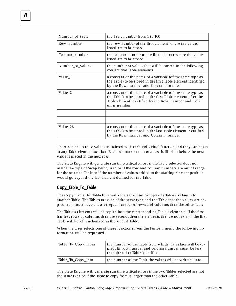
8
8-36 ECLiPS English Control Language Programming System User’s Guide – March 1998 GFK-0732B
Number_of_table the Table number from 1 to 100
Row_number the row number of the first element where the valueslisted are to be stored
Column_number the column number of the first element where the valueslisted are to be stored
Number_of_values the number of values that will be stored in the followingconsecutive Table elements
Value_1 a constant or the name of a variable (of the same type asthe Table) to be stored in the first Table element identifiedby the Row_number and Column_number
Value_2 a constant or the name of a variable (of the same type asthe Table) to be stored in the first Table element after theTable element identified by the Row_number and Col-umn_number
..
..
Value_28 a constant or the name of a variable (of the same type asthe Table) to be stored in the last Table element identifiedby the Row_number and Column_number
There can be up to 28 values initialized with each individual function and they can beginat any Table element location. Each column element of a row is filled in before the nextvalue is placed in the next row.
The State Engine will generate run time critical errors if the Table selected does notmatch the type of Swap being used or if the row and column numbers are out of rangefor the selected Table or if the number of values added to the starting element positionwould go beyond the last element defined for the Table.
Copy_Table_To_Table
The Copy_Table_To_Table function allows the User to copy one Table’s values intoanother Table. The Tables must be of the same type and the Table that the values are co-pied from must have a less or equal number of rows and columns than the other Table.
The Table’s elements will be copied into the corresponding Table’s elements. If the firsthas less rows or columns than the second, then the elements that do not exist in the firstTable will be left unchanged in the second Table.
When the User selects one of these functions from the Perform menu the following in-formation will be requested:
Table_To_Copy_From the number of the Table from which the values will be co-pied. Its row number and column number must be lessthan the other Table identified
Table_To_Copy_Into �he number of the Table the values will be written into.
The State Engine will generate run time critical errors if the two Tables selected are notthe same type or if the Table to copy from is larger than the other Table.
8
8-37GFK-0732B Chapter 8 Referemce
Table Uses
There are many uses for the Table functions. As an example, the Table functions are valu-able in applications where the set up of parameters varies depending on the productunder manufacture on the process line. Batch process recipes or flexible manufacturingassembly lines are examples.
The ECLiPS program can be written using English name variables for parametersthroughout with statements such as:
If Oven_temp_1 is greater than Melting_point ...
used throughout the program description of the process. Then in a State, lets call it theSelect_Product State, by using the Swap_Table_Value_Flt function, the variable Melt-ing_Point can be made equal to one of the elements of Table 1, where Table 1 containsthe parameters for this particular product run.
Using the Init_Table_Float, Tables containing parameters for each style of product thatcan be made on the line can be initialized. When the Operator selects a style of productin the Select_Product_Style State, the Copy_Table_To_Table function can be used tomove those parameters into Table 1, the Table in which Melting_Point finds its values forthis style and product run.
BCD I/O Representation
General
At times input and output devices are used for data entry or display that use BCD repre-sentation. Thumb wheel switches and LCD displays are possible examples.
The devices are connected either to digital inputs or digital outputs where 4 hardwareinputs or outputs represent 1 digit of the display. The display or switch then uses abinary code representation from 0 to 9. There are 16 total possibilities (4 outputs or in-puts represent 2 to the 4th or 16 possible combinations), and the remaining 6 are usedfor such things as minus sign, decimal point and null or space character on a display.
The two functions, BCD_In_Conversion and Output_BCD_Conversion allow the User todesignate a series of consecutive digital inputs or outputs to be treated as if they aregroups of 4 BCD digits. The functions then translate between the I/O and either StateEngine integer or float variables.
BCD_In_Convert
The BCD_In_Convert translates between a series of digital inputs and an integer or floatvariable. The User specifies the name of the first digital input in the series and the num-ber of BCD digits (4 inputs per digit) that represent the variable. The User also specifiesthe type of variable and the name of the variable to store the converted value.
The inputs will be taken in hardware consecutive order, and the number of digits can beon more than one block or card as long as the cards have consecutive addresses. TheUser only need define with an English name the first digital input and initialize theblocks or cards involved.
BCD uses the standard binary representation for the numerical digits 0 to 9. There is notrue standard for the minus sign or decimal point character. Therefore the function has

8
8-38 ECLiPS English Control Language Programming System User’s Guide – March 1998 GFK-0732B
the provision for the User to optionally specify the hexadecimal number, #A, #B, #C,#D, #E, or #F, (where # means hexadecimal number to ECLiPS), that is the pattern forthese two characters.
The function parameters are:
Starting_input the English name of the first digital input in the string ofconsecutive inputs that form the BCD digits
Number_of_BCD_digits the number of BCD digits. The number of digital inputs inthe string will be 4 times the number of digits.
Variable_name the name of the variable to store the translated value
Variable_type the type of variable either integer or float
Minus_sign_pattern a hexadecimal number from A to F that gives the patternfor a digit that should be recognized as the minus sign.
Decimal_point_pat a hexadecimal number from A to F that gives the patternfor a digit that should be recognized as the decimal point.Note the minus sign and decimal point are optional. Aminus sign can be specified without a decimal point, but ifa decimal point is specified the minus sign must also bespecified.
Output_BCD_Convert
The Output_BCD_Convert translates between a an integer or float variable and a seriesof digital outputs. The User specifies the name of the first digital output in the series andthe number of BCD digits (4 outputs per digit) that represent the variable. The User alsospecifies the type of variable and the name of the variable where the value to be con-verted is stored.
The outputs are in hardware consecutive order, and the number of digits can be on morethan one block or card as long as the cards have consecutive addresses. The User onlyneed define with an English name the first digital output and initialize the blocks orcards involved.
BCD uses the standard binary representation for the numerical digits 0 to 9. There is notrue standard for the minus sign or decimal point or null (space) character. Therefore thefunction has the provision for the User to optionally specify the hexadecimal number,#A, #B, #C, #D, #E, or #F, (where # means hexadecimal number to ECLiPS), that is thepattern for these three characters.
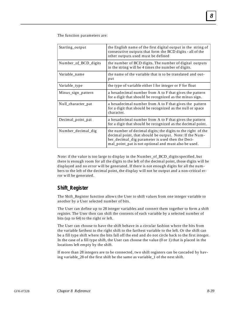
8
8-39GFK-0732B Chapter 8 Referemce
The function parameters are:
Starting_output the English name of the first digital output in the string ofconsecutive outputs that form the BCD digits - all of theother outputs used must be defined
Number_of_BCD_digits the number of BCD digits. The number of digital outputsin the string will be 4 times the number of digits.
Variable_name the name of the variable that is to be translated and out-put
Variable_type the type of variable either I for integer or F for float
Minus_sign_pattern a hexadecimal number from A to F that gives the patternfor a digit that should be recognized as the minus sign.
Null_character_pat a hexadecimal number from A to F that gives the patternfor a digit that should be recognized as the null or spacecharacter.
Decimal_point_pat a hexadecimal number from A to F that gives the patternfor a digit that should be recognized as the decimal point.
Number_decimal_dig the number of decimal digits; the digits to the right of thedecimal point, that should be output. Note: If the Num-ber_decimal_dig parameter is used then the Deci-mal_point_pat is not optional and must also be used.
Note: if the value is too large to display in the Number_of_BCD_digits specified, butthere is enough room for all the digits to the left of the decimal point, those digits will bedisplayed and no error will be generated. If there is not enough digits for all the num-bers to the left of the decimal point, the display will not be output and a non-critical er-ror will be generated.
Shift_RegisterThe Shift_Register function allows the User to shift values from one integer variable toanother by a User selected number of bits.
The User can define up to 28 integer variables and connect them together to form a shiftregister. The User then can shift the contents of each variable by a selected number ofbits (up to 64) to the right or left.
The User can choose to have the shift behave in a circular fashion where the bits fromthe variable farthest to the right shift to the farthest variable to the left. Or the shift canbe a fill type shift where the bits fall off the end and do not circle back to the first integer.In the case of a fill type shift, the User can choose the value (0 or 1) that is placed in thelocations left empty by the shift.
If more than 28 integers are to be connected, two shift registers can be cascaded by hav-ing variable_28 of the first shift be the same as variable_1 of the next shift.
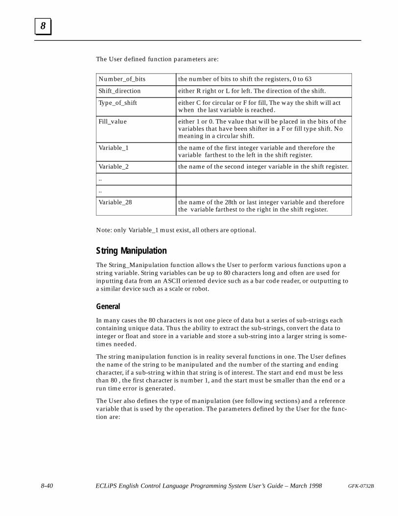
8
8-40 ECLiPS English Control Language Programming System User’s Guide – March 1998 GFK-0732B
The User defined function parameters are:
Number_of_bits the number of bits to shift the registers, 0 to 63
Shift_direction either R right or L for left. The direction of the shift.
Type_of_shift either C for circular or F for fill, The way the shift will actwhen the last variable is reached.
Fill_value either 1 or 0. The value that will be placed in the bits of thevariables that have been shifter in a F or fill type shift. Nomeaning in a circular shift.
Variable_1 the name of the first integer variable and therefore thevariable farthest to the left in the shift register.
Variable_2 the name of the second integer variable in the shift register.
..
..
Variable_28 the name of the 28th or last integer variable and thereforethe variable farthest to the right in the shift register.
Note: only Variable_1 must exist, all others are optional.
String ManipulationThe String_Manipulation function allows the User to perform various functions upon astring variable. String variables can be up to 80 characters long and often are used forinputting data from an ASCII oriented device such as a bar code reader, or outputting toa similar device such as a scale or robot.
General
In many cases the 80 characters is not one piece of data but a series of sub-strings eachcontaining unique data. Thus the ability to extract the sub-strings, convert the data tointeger or float and store in a variable and store a sub-string into a larger string is some-times needed.
The string manipulation function is in reality several functions in one. The User definesthe name of the string to be manipulated and the number of the starting and endingcharacter, if a sub-string within that string is of interest. The start and end must be lessthan 80 , the first character is number 1, and the start must be smaller than the end or arun time error is generated.
The User also defines the type of manipulation (see following sections) and a referencevariable that is used by the operation. The parameters defined by the User for the func-tion are:
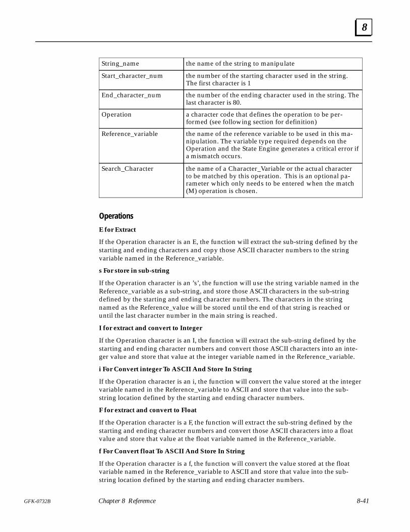
8
8-41GFK-0732B Chapter 8 Referemce
String_name the name of the string to manipulate
Start_character_num the number of the starting character used in the string.The first character is 1
End_character_num the number of the ending character used in the string. Thelast character is 80.
Operation a character code that defines the operation to be per-formed (see following section for definition)
Reference_variable the name of the reference variable to be used in this ma-nipulation. The variable type required depends on theOperation and the State Engine generates a critical error ifa mismatch occurs.
Search_Character the name of a Character_Variable or the actual characterto be matched by this operation. This is an optional pa-rameter which only needs to be entered when the match(M) operation is chosen.
Operations
E for Extract
If the Operation character is an E, the function will extract the sub-string defined by thestarting and ending characters and copy those ASCII character numbers to the stringvariable named in the Reference_variable.
s For store in sub-string
If the Operation character is an ’s’, the function will use the string variable named in theReference_variable as a sub-string, and store those ASCII characters in the sub-stringdefined by the starting and ending character numbers. The characters in the stringnamed as the Reference_value will be stored until the end of that string is reached oruntil the last character number in the main string is reached.
I for extract and convert to Integer
If the Operation character is an I, the function will extract the sub-string defined by thestarting and ending character numbers and convert those ASCII characters into an inte-ger value and store that value at the integer variable named in the Reference_variable.
i For Convert integer To ASCII And Store In String
If the Operation character is an i, the function will convert the value stored at the integervariable named in the Reference_variable to ASCII and store that value into the sub-string location defined by the starting and ending character numbers.
F for extract and convert to Float
If the Operation character is a F, the function will extract the sub-string defined by thestarting and ending character numbers and convert those ASCII characters into a floatvalue and store that value at the float variable named in the Reference_variable.
f For Convert float To ASCII And Store In String
If the Operation character is a f, the function will convert the value stored at the floatvariable named in the Reference_variable to ASCII and store that value into the sub-string location defined by the starting and ending character numbers.
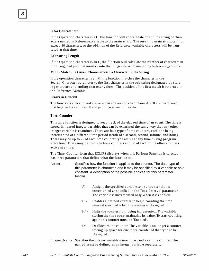
8
8-42 ECLiPS English Control Language Programming System User’s Guide – March 1998 GFK-0732B
C for Concatenate
If the Operation character is a C, the function will concatenate or add the string of char-acters named in Reference_variable to the main string. The resulting main string can notexceed 80 characters, so the addition of the Reference_variable characters will be trun-cated at that time.
L for string Length
If the Operation character is an L, the function will calculate the number of characters inthe string, and put that number into the integer variable named by Reference_variable.
M for Match the Given Character with a Character in the String
If the operation character is an M, the function matches the character in theSearch_Character parameter to the first character in the sub-string designated by start-ing character and ending character values. The position of the first match is returned inthe Reference_Variable.
Errors in General
The functions check to make sure when conversions to or from ASCII are performedthat legal values will result and produce errors if they do not.
Time Counter
This time function is designed to keep track of the elapsed time of an event. The time isstored in named integer variables that can be examined the same way that any otherinteger variable is examined. There are four type of time counters, each one beingincremented at a different time period (tenth of a second, second, minute, and hour).There may be up to 25 of each time counter type active at any time during programexecution. There may be 10 of the hour counters and 30 of each of the other countersactive at a time.
The Time_Counter form that ECLiPS displays when this Perform Function is selected,has three parameters that define what the function call:
Action Specifies how the function is applied to the counter. The data type ofthis parameter is character, and it may be specified by a variable or as aconstant. A description of the possible choices for this parameter follows:
’A’ - Assigns the specified variable to be a counter that isincremented as specified in the Time_Interval parameter.The variable is incremented only when it is enabled.
’E’ - Enables a defined counter to begin counting the timeinterval specified when the counter is ’Assigned’.
’H’ - Halts the counter from being incremented. The variablestoring the time count maintains its value. To start countingagain this counter must be ’Enabled’.
’D’ - Deallocates the counter. The variable is no longer a counter freeing up space for one more counter of that type to be
’Assigned’.
Integer_Name Specifies the integer variable name to be used as a time counter. Thenamed must be defined as an integer variable separately.

8
8-43GFK-0732B Chapter 8 Referemce
Time_Interval Specifies what time period must pass before incrementing the counter.The data type of this parameter is character and is specified by either avariable or a constant. This parameter is required only if the action
parameter is an ’A’(Assign). For other actions this parameter may be leftblank. A description of the possible choices for this parameter follows:
T - Specifies the counter to be incremented every tenth of a second.
’S’ - Specifies the counter to be incremented every second.
’M’ - Specifies the counter to be incremented every minute.
’H’ - Specifies the counter to be incremented every hour.
NoteEach of the time counters has a maximum value of 32,767. If you expectthe value is going to exceed the maximum, use the next larger countertype. For example, use a minute counter instead of a second counter.After reaching the maximum, the counter still continues to increment,becoming a negative number.
Specialized Perform FunctionsAll off the above functions have specific parameters which are passed to the function.These parameters are all chosen by filling in similar forms which specify parameter typeand whether or not it is required. The following performs have unique ways that theoperations are specified.
Display Date and TimeThis function displays the current date and time in the desired format. After choosingthis option a form is displayed to enter the Name of the State that is created, the formatof the display, the communications port to send the information and the State to branchto after the operation is completed.
Get User InputThis function enters program text used to retrieve information through a communica-tions port. A form is displayed for entering the following options:
Current State - Name of the State that is created.��� � ����� " ������ �� ��� ���� ��� ������ ������ ��� ������ �� ����� !���
��������� �� " ������ ������� ���� ��� �� ����� ���� ������ �����
����� � �� ��� " � �� ��� �� � ������ ��� �����
���� ���� " ����� ���� �� �����
�� ��� � � �� " � �� �� � ������� ����� ��� ���� ������� �� ����������
User MenuThis function will display a menu of up to 10 items and then wait for the user to enter aselection. If the selection is valid, it will branch to desired State for that selection. This isvery useful when creating a user interface for the control program.
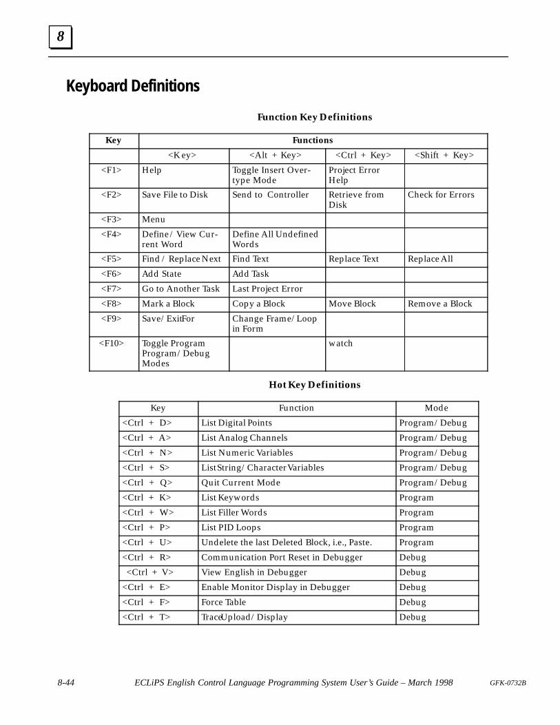
8
8-44 ECLiPS English Control Language Programming System User’s Guide – March 1998 GFK-0732B
Keyboard Definitions
Function Key Definitions
Key Functions
<K ey> <Alt + Key> <Ctrl + Key> <Shift + Key>
<F1> Help Toggle Insert Over-type Mode
Project ErrorHelp
<F2> Save File to Disk Send to Controller Retrieve fromDisk
Check for Errors
<F3> Menu
<F4> Define / View Cur-rent Word
Define All UndefinedWords
<F5> Find / Replace Next Find Text Replace Text Replace All
<F6> Add State Add Task
<F7> Go to Another Task Last Project Error
<F8> Mark a Block Copy a Block Move Block Remove a Block
<F9> Save/Exit For Change Frame/ Loopin Form
<F10> Toggle ProgramProgram/DebugModes
watch
Hot Key Definitions
Key Function Mode
<Ctrl + D> List Digital Points Program/Debug
<Ctrl + A> List Analog Channels Program/Debug
<Ctrl + N> List Numeric Variables Program/Debug
<Ctrl + S> List String/Character Variables Program/Debug
<Ctrl + Q> Quit Current Mode Program/Debug
<Ctrl + K> List Keywords Program
<Ctrl + W> List Filler Words Program
<Ctrl + P> List PID Loops Program
<Ctrl + U> Undelete the last Deleted Block, i.e., Paste. Program
<Ctrl + R> Communication Port Reset in Debugger Debug
<Ctrl + V> View English in Debugger Debug
<Ctrl + E> Enable Monitor Display in Debugger Debug
<Ctrl + F> Force Table Debug
<Ctrl + T> Trace Upload/Display Debug
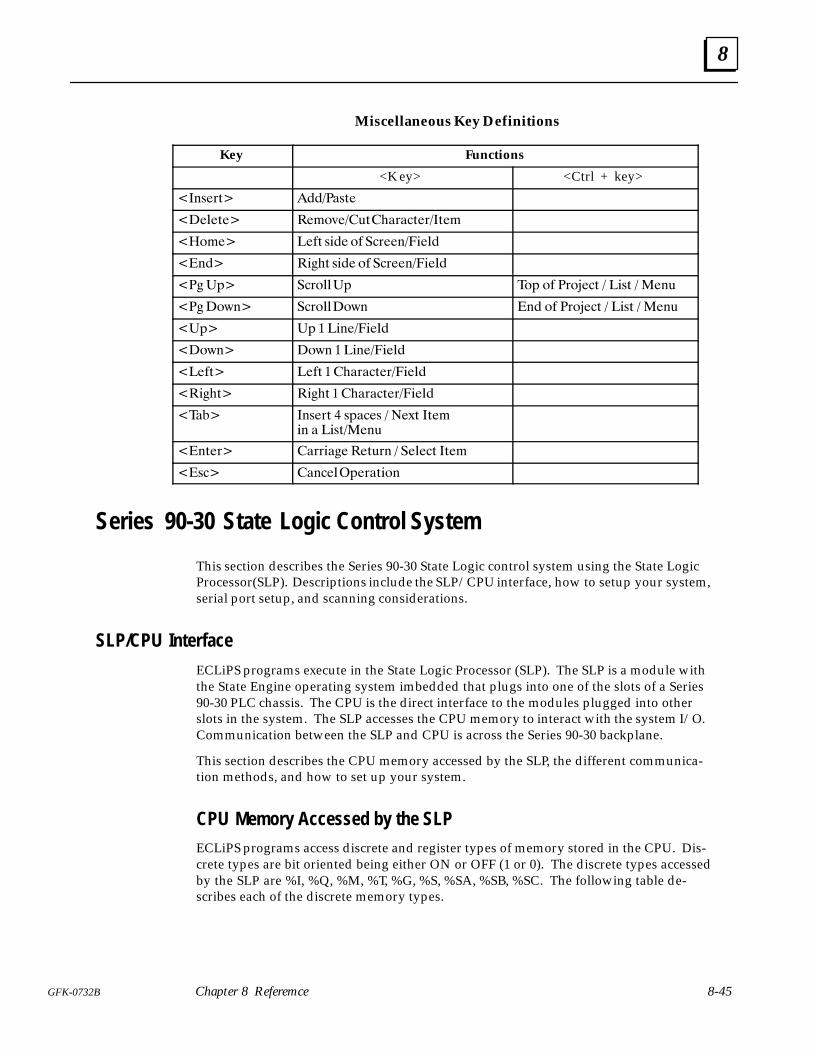
8
8-45GFK-0732B Chapter 8 Referemce
Miscellaneous Key Definitions
Key Functions
<K ey> <Ctrl + key>
� #'�&(� ������'(�
��!�(�� ��"$*���)(���&��(�&� (�"
��$"�� ���( '��� $� ��&��#����!�
�#�� ����( '��� $� ��&��#����!�
��� �%� ��&$!!�% �$% $� �&$ ��( � ��'( � ��#)
��� $+#� ��&$!!$+# #� $� �&$ ��( � ��'( � ��#)
��%� �% � ��#�����!�
�$+#� $+# � ��#�����!�
����(� ���( � ���&��(�&����!�
�����(� ����( � ���&��(�&����!�
����� #'�&( � '%���' � ��,( (�"�# � ��'(���#)
�#(�&� ��&&���� ��()&# � ��!��( (�"
�'�� ��#��!�%�&�(�$#
Series 90-30 State Logic Control System
This section describes the Series 90-30 State Logic control system using the State LogicProcessor(SLP). Descriptions include the SLP/CPU interface, how to setup your system,serial port setup, and scanning considerations.
SLP/CPU Interface
ECLiPS programs execute in the State Logic Processor (SLP). The SLP is a module withthe State Engine operating system imbedded that plugs into one of the slots of a Series90-30 PLC chassis. The CPU is the direct interface to the modules plugged into otherslots in the system. The SLP accesses the CPU memory to interact with the system I/O.Communication between the SLP and CPU is across the Series 90-30 backplane.
This section describes the CPU memory accessed by the SLP, the different communica-tion methods, and how to set up your system.
CPU Memory Accessed by the SLPECLiPS programs access discrete and register types of memory stored in the CPU. Dis-crete types are bit oriented being either ON or OFF (1 or 0). The discrete types accessedby the SLP are %I, %Q, %M, %T, %G, %S, %SA, %SB, %SC. The following table de-scribes each of the discrete memory types.
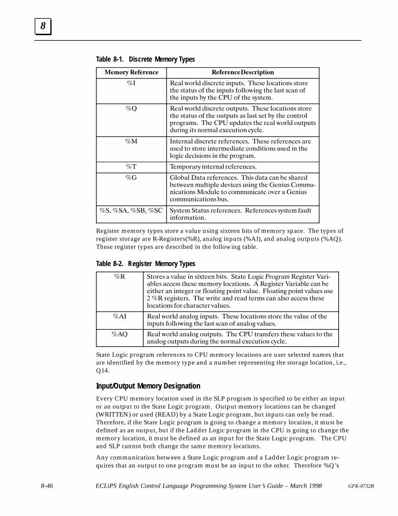
8
8-46 ECLiPS English Control Language Programming System User’s Guide – March 1998 GFK-0732B
Table 8-1. Discrete Memory Types
��� � ���� ��� ���� ������� �����
�� ���� )"$�� ��%�$�&� �!#'&%� ���%� �"��&�"!% %&"$�&�� %&�&'% "� &�� �!#'&% �"��")�!� &�� ��%& %��! "�&�� �!#'&% �+ &�� ��� "� &�� %+%&� �
�� ���� )"$�� ��%�$�&� "'&#'&%� ���%� �"��&�"!% %&"$�&�� %&�&'% "� &�� "'&#'&% �% ��%& %�& �+ &�� �"!&$"�#$"�$� %� ��� ��� '#��&�% &�� $��� )"$�� "'&#'&%�'$�!� �&% !"$ �� �*��'&�"! �+����
�� �!&�$!�� ��%�$�&� $���$�!��%� ���%� $���$�!��% �$�'%�� &" %&"$� �!&�$ ����&� �"!��&�"!% '%�� �! &���"��� ����%�"!% �! &�� #$"�$� �
�� �� #"$�$+ �!&�$!�� $���$�!��%�
�� ��"��� �&� $���$�!��%� ���% ��&� ��! �� %��$����&)��! '�&�#�� ��(���% '%�!� &�� ��!�'% �" ',!���&�"!%�"�'�� &" �" '!���&� "(�$ � ��!�'%�" '!���&�"!% �'%�
������� ���� ��� �+%&� �&�&'% $���$�!��%� ����$�!��% %+%&� ��'�&�!�"$ �&�"!�
Register memory types store a value using sixteen bits of memory space. The types ofregister storage are R-Registers(%R), analog inputs (%AI), and analog outputs (%AQ).These register types are described in the following table.
Table 8-2. Register Memory Types
�� �&"$�% � (��'� �! %�*&��! ��&%� �&�&� "��� �$"�$� ����%&�$ ��$�,����% ����%% &��%� � "$+ �"��&�"!%� � ����%&�$ ��$����� ��! ����&��$ �! �!&���$ "$ ��"�&�!� #"�!& (��'�� �"�&�!� #"�!& (��'�% '%�� �� $���%&�$%� ��� )$�&� �!� $��� &�$ % ��! ��%" ����%% &��%��"��&�"!% �"$ ���$��&�$ (��'�%�
��� ���� )"$�� �!��"� �!#'&%� ���%� �"��&�"!% %&"$� &�� (��'� "� &���!#'&% �"��")�!� &�� ��%& %��! "� �!��"� (��'�%�
��� ���� )"$�� �!��"� "'&#'&%� ��� ��� &$�!%��$% &��%� (��'�% &" &���!��"� "'&#'&% �'$�!� &�� !"$ �� �*��'&�"! �+����
State Logic program references to CPU memory locations are user selected names thatare identified by the memory type and a number representing the storage location, i.e.,Q14.
Input/Output Memory Designation
Every CPU memory location used in the SLP program is specified to be either an inputor an output to the State Logic program. Output memory locations can be changed(WRITTEN) or used (READ) by a State Logic program, but inputs can only be read.Therefore, if the State Logic program is going to change a memory location, it must bedefined as an output, but if the Ladder Logic program in the CPU is going to change thememory location, it must be defined as an input for the State Logic program. The CPUand SLP cannot both change the same memory locations.
Any communication between a State Logic program and a Ladder Logic program re-quires that an output to one program must be an input to the other. Therefore %Q’s
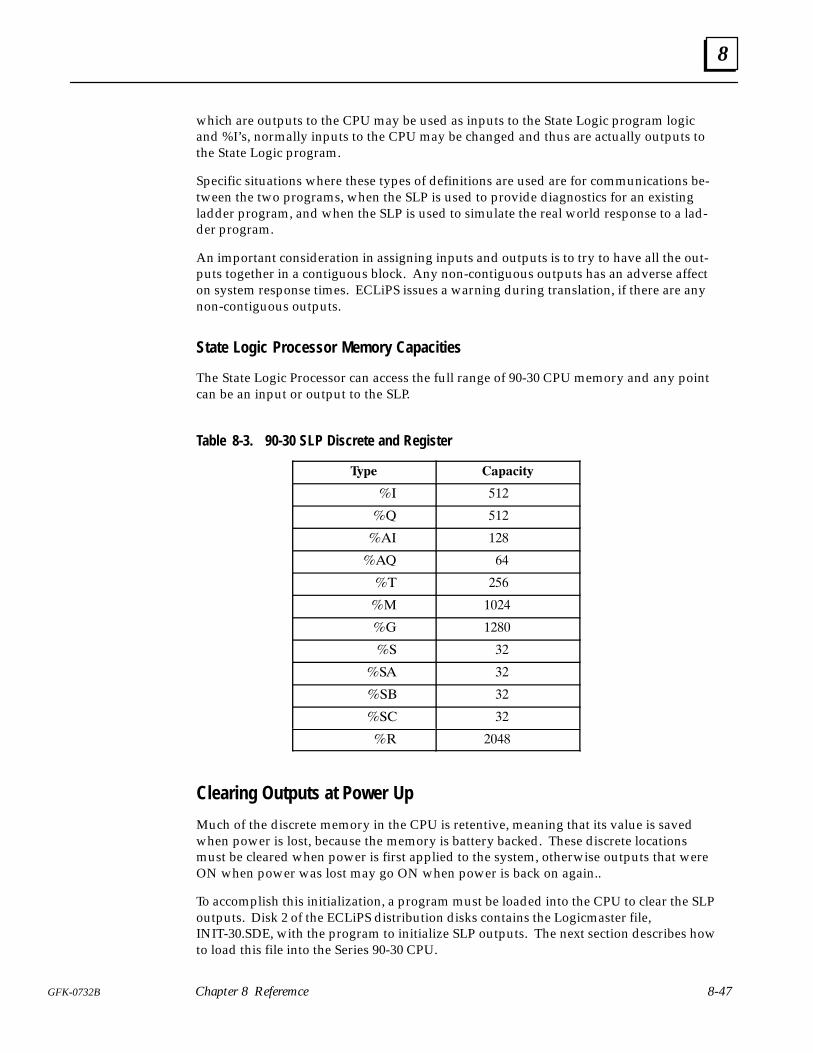
8
8-47GFK-0732B Chapter 8 Referemce
which are outputs to the CPU may be used as inputs to the State Logic program logicand %I’s, normally inputs to the CPU may be changed and thus are actually outputs tothe State Logic program.
Specific situations where these types of definitions are used are for communications be-tween the two programs, when the SLP is used to provide diagnostics for an existingladder program, and when the SLP is used to simulate the real world response to a lad-der program.
An important consideration in assigning inputs and outputs is to try to have all the out-puts together in a contiguous block. Any non-contiguous outputs has an adverse affecton system response times. ECLiPS issues a warning during translation, if there are anynon-contiguous outputs.
State Logic Processor Memory Capacities
The State Logic Processor can access the full range of 90-30 CPU memory and any pointcan be an input or output to the SLP.
Table 8-3. 90-30 SLP Discrete and Register
��� �������
�� ���
�� ���
�� ��
�� ��
�� ���
�� ����
� ���
�� ��
�� ��
��� ��
��� ��
�� ���
Clearing Outputs at Power Up
Much of the discrete memory in the CPU is retentive, meaning that its value is savedwhen power is lost, because the memory is battery backed. These discrete locationsmust be cleared when power is first applied to the system, otherwise outputs that wereON when power was lost may go ON when power is back on again..
To accomplish this initialization, a program must be loaded into the CPU to clear the SLPoutputs. Disk 2 of the ECLiPS distribution disks contains the Logicmaster file,INIT-30.SDE, with the program to initialize SLP outputs. The next section describes howto load this file into the Series 90-30 CPU.
8
8-48 ECLiPS English Control Language Programming System User’s Guide – March 1998 GFK-0732B
Watchdog TimerThe watchdog timer is designed to stop the control system if the SLP fails or stopscommunicating with the CPU. ECLiPS provides an option to include a watchdog Taskinto the State Logic program every time a new project is started. The watchdog Task canalso be added to the program at any time by importing the watchdog project that isstored in the same directory as ECLiPS.
This Task is designed to work in conjunction with rungs of logic executing in the CPUprogram. The rungs of ladder logic are included in the file called WATCHDOG.SDE ondisk 2 of the ECLiPS distribution disks. See the section on setting up the system CPU, foran explanation of how to incorporate this file with an existing ladder program. Thewatchdog rungs of ladder logic should not be used without the watchdog Task includedin the State Logic program.
If the watchdog timer does shut down the system, the fault, “PLC CPU Software Fault” ,appears in the fault table.
The default watchdog system provided is a generic system that does add some time tothe scan time of the system. To minimize the scan time impact, customize the watchdogTask and ladder logic by changing the Heartbeat and SLP Running outputs from %Gmemory type to %Q and assigning the %Qs to be contiguous with the %Qs in thesystem. Remember that this change must be made to the Ladder Logic program in theCPU as well as the State Logic program in the SLP.
Series 90-30 System Setup ProceduresThere are three tasks to accomplish in getting the Series 90-30 CPU ready for State LogicControl. These tasks are configuring the CPU for the modules that are plugged into eachone of the system slots, loading the file with the initialization program into the CPU pro-gram memory, and finally placing the CPU into RUN mode with the outputs enabled.
Use the Logicmaster 90 software package that comes with ECLiPS to accomplish thesetasks. The following steps describe how to use Logicmaster 90 to perform these func-tions.
1. After starting Logicmaster, select the configuration package, key <F2>.
2. Create a program folder for your application by entering a folder name.
3. Setup the configuration of each chassis slot to match the hardware used in thesystem, key <F1>. Configure the SLP module as a PCM and the ConfigurationMode as PCM CFG. Press <Esc> when completed.
4. The configuration is now complete so press <Esc> again to exit the configurationpackage.
5. Enter the Programmer Package by pressing <F1>. Then select the folder that youjust created in the Configuration Package.
6. Select Program Display/Edit <F1>
7. Select Region <F9>
8. Select Include <F4>
9. Now put ECLiPS disk 2 into drive A and enter the Ladder Logic program file nameselected from the table above as follows: A:\INIT-30. This operation loads the
8
8-49GFK-0732B Chapter 8 Referemce
Ladder Logic program from the file and incorporates it with any existing Ladderprogram.
10. Press <Enter> and the program file is incorporated into the program. The LadderLogic program for the watchdog timer is called WATCHDOG.SDE and is alsoprovided on disk number 2. Repeat this procedure to incorporate the watchdog filewith the other rungs in the CPU. The same watchdog file is used for all CPU andinterface types.
11. Press <Esc> to return to the Programmer Package starting screen. Then press<F3> for PLC Control and Status.
12. Press the <Tab> key until RUN/OUT EN is displayed in the block and press<Enter>.
The CPU is now set up for State Logic program execution. The chassis slot I/O hardwareis configured, the Ladder Logic program is loaded into the CPU, and the CPU is in RUNmode with outputs enabled.
Serial Ports
The State Logic Processor (SLP) has two serial ports. One of these ports can be desig-nated to be the Programming Port, the one which connects the SLP to ECLiPS or OnTOP.Port 1 is an RS-232port and port 2 is an RS-422/485 type port. See the sections on Writeand Read Terms in the Language Description section of this manual for a discussion ofhow to program communications through the serial ports.
Configuring Serial PortsThe attributes of each serial port may be changed by the State Logic Control program.The parameters are changed by the Set_Commport keyword. There is a discussion ofusing the Set_Commport keyword in the section that explains the LIST menu options.
Designating the Programming PortThe programming port is the State Processor serial port to which ECLiPS or OnTOP isconnected. If ECLiPS or OnTOP is not connected to the programming port, the SLP can-not communicate to these software packages.
Port one is the default programming port. To change the programming port select the“State Engine Configuration” option from the Debug Mode PROJECT menu.
CCM2 Protocol Serial PortCCM2 protocol is a standard open communications protocol defined by GE Fanuc. TheState Engine acts as a slave in a master-to-slave architecture. The remote master com-puter must poll to retrieve data from the State Engine. All communications are initiatedby the host.
The CCM2 protocol defines the message structure, framing, error checking and han-dling, and timing for all message types. At the lower physical level, the serial port of theState Engine is electrically RS-232 and can be configured for any Baud rate, parity, andstop bits desired via a command in the program executing in the State Engine. Use the
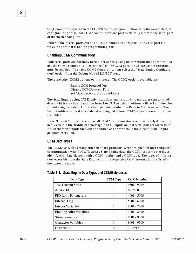
8
8-50 ECLiPS English Control Language Programming System User’s Guide – March 1998 GFK-0732B
Set_Commport keyword in the ECLiPS control program followed by the parameters, toconfigure the port so that CCM2 communications port electrically matches the serial portof the master computer.
Either of the 2 serial ports can be a CCM2 Communications port. The CCM port is al-ways the port that is not the programming port.
Enabling CCM2 Communication
Both serial ports are normally normal serial ports using no communications protocol. Touse the CCM2 communications protocol on the CCM port, the CCM2 Communicationsmust be enabled. To enable CCM2 Communications select the “State Engine Configura-tion” option from the Debug Mode PROJECT menu.
There are other CCM2 options on this menu. The CCM2 options available are:
Enable CCM Protocol Port��'��!� ��&$($�$!�$&(
��( � �&$($�$! �(�(�$#���&�''
The State Engine using CCM2 only recognizes and responds to messages sent to its ad-dress, which may be any number from 1 to 89. The default address will be 1 and the Usershould assign a Station Address to match the number the Remote Master expects. TheStation Address should be validated or assigned before CCM2 protocol communicationsis enabled.
If the “Disable” function is chosen, all CCM2 communications is immediately discontin-ued, even if in the middle of a message, and all inputs on that serial port are taken to beASCII character inputs that will be handled as appropriate to the current State Engineprogram execution.
CCM Data Types
The CCM2, as well as many other standard protocols, were designed for host computercommunication with PLCs. To access State Engine data, the CCM host computer mustidentify each data element with a CCM number and a CCM type. The types of informa-tion accessible from the State Engine plus the respective CCM information are listed inthe following table.
Table 8-4. State Engine Data Types and CCM References
�� � ��� ��� ��� �������
��' )&&�#( �(�(� � ���� * ����
�#�!$� ��� � � * ����
��� �$$% ��&�"�(�&' � ���� * ����
�#(�&#�!�!�� � ���� * ����
�#(���& ��&���!�' � ���� * ���
�!$�(�#� �$�#( ��&���!�' � ��� * ���
�(&�#� ��&���!�' � ��� * ����
��&��(�& ��&���!�' � ���� * ����
��'�&�(� ��� � � * ����
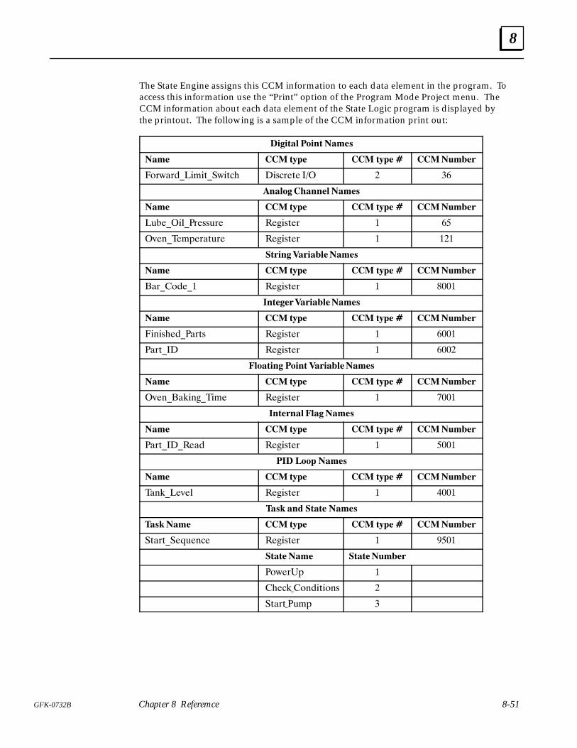
8
8-51GFK-0732B Chapter 8 Referemce
The State Engine assigns this CCM information to each data element in the program. Toaccess this information use the “Print” option of the Program Mode Project menu. TheCCM information about each data element of the State Logic program is displayed bythe printout. The following is a sample of the CCM information print out:
������� ����� ����
��� �� � �� �� � �� � �������
�&).�)���!$!+��.!+� �!*�)�+� ��� � �
������ ������� ����
��� �� � �� �� � �� � �������
�,����!#��)�**,)� ���!*+�) � �
�-�%���$'�)�+,)� ���!*+�) � ���
������ ������������
��� �� � �� �� � �� � �������
�)��&���� ���!*+�) � ����
�������������������
��� �� � �� �� � �� � �������
�!%!* �����)+* ���!*+�) � ���
��)+��� ���!*+�) � ���
�������� ����� ������������
��� �� � �� �� � �� � �������
�-�%� �"!%���!$� ���!*+�) � ���
�������� ��������
��� �� � �� �� � �� � �������
��)+�������� ���!*+�) � ����
��� ���� ����
��� �� � �� �� � �� � �������
��%"���-�# ���!*+�) � ����
��� ��� ����� ����
��� ��� �� � �� �� � �� � �������
�+�)+���(,�%�� ���!*+�) � ����
�������� ����������
�&.�)�' �
� ��" �&%�!+!&%* �
�+�)+ �,$' �
8
8-52 ECLiPS English Control Language Programming System User’s Guide – March 1998 GFK-0732B
Part of the CCM protocol is for the message from the Master to define the type, startingregister and total number of bytes to be read or written. The Master needs to specify thecorrect number of bytes depending upon the type of variable. The byte count and otherconsiderations for each of the data types follow:
Task Current State The value stored in the designated register represents thecurrent State of this Task. Current States can be changed andmonitored using the CCM protocol. This value uses 1 regis-ter or 2 bytes in a CCM message. The inactive State is repre-sented by a value of 0. Warning: If an invalid number iswritten to put a Task into a State that does not exist, the pro-gram continues to execute but that Task does nothing.
�������� �� ���� �� ( ��)� )-%� *(�( � '�� ()�' $' � �-)�( # � ��� "�((����
#- ��� ()�' ��' ��!�( )��) �'� #)���'( �'� # )� ( �!�((�
��� ���� ���� � �� ���� ���(� +�!*�( *(� � '�� ()�'( $' � �-)�( $� (%��� �#� �'� ()$'��
# � �$'"�)� �$ *(� )��(� +�!*�( )�� �$() �$"%*)�' "*()
�� ��!� )$ #)�'%'�) )�� � �-)�( �( �# � �!$�) #� %$ #)
#*"��'� #- ��� ()�' ��' ��!�( )��) �'� �!$�) #� %$ #) +�!*�(
�'� # )� ( �!�((�
����� � ������������� ���(� %$ #)( �'� '�%'�(�#)�� �- )�� ' ��) "$() � ) $� )��
)'�#(��''�� �-)�� � '�%'�(�#)( �� �#� � � '�%'�(�#)( ����
�$)� )��) ( #�� � � )�! %$ #)( �'� ��� �- ����*!)� �# $*)%*)
(�) �� , )� ��� , !! $#!- �� �� �$' $#� (��# �#� )��# �)�)�
#� #� $%�'�) #� (-()�" )*'#( ) ����
������ ��� �� Each flag is represented by a bit in the data transmitted. Thefirst bit refers to the flag specified and the other bits repre-sent other flags. At least one byte or 8 flags are representedin every transmission. Therefore, when writing to flags, atleast 8 flags ar set at a time. State Logic treats flags as dis-crete l/O in that they are OFF by default. Therefore a flag setthrough CCM is ON for one scan only. The State Logic oper-ating system turns OFF the flag in the next scan.
�� ��� ������������� #�!$� ��� �'� �!$�) #� %$ #) +�!*�( �#� )��'��$'� '�&* '� �
'�� ()�'( $' � �-)�(� ��� �$() "*() �� ��!� )$ #)�'%'�) )� (
+�!*� �( �# � �!$�) #� %$ #) #*"��'� #�!$� ���##�!(
��( �#�)�� � �� (%��� ���##�!( �'� #)���' #�$'"�) $# *( #�
$#!- � $� )�� � �-)�(�
������ � �� ���� �)' #� +�' ��!�( ��# �� *% )$ � �-)�( $' �� '�� ()�'( !$#��
�� � ����� �� ���� ���'��)�'( �'� � �-)��
�� ���� � ������ ���'� �'� �� %�'�"�)�'( �(($� �)�� , )� ���� ��� !$$%� ���
'�� ()�' #*"��' � (%!�-�� # )�� %' #)$*) '�%'�(�#)( )�� #*".
��' $� )�� � '() %�'�"�)�' �$' )�� !$$%� ��� !$$% ��� #*".
��'( , !! �� # "*!) %!�( $� �� ($ )��) � )�� � '() !$$% ( ����
)�� (��$#� ( ����� ��� $'��' $� )�� %�'�"�)�'( ( ! ()�� #
)���$!!$, #�)��!��
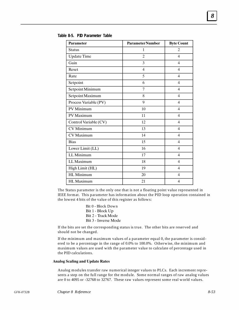
8
8-53GFK-0732B Chapter 8 Referemce
Table 8-5. PID Parameter Table
������� ������������� ���� �����
�+�+,* � �
�(��+��"%� � �
��"& � �
��*�+ � �
��+� �
��+('"&+ �
��+('"&+�"&"%,% � �
��+('"&+��/"%,% � �
�)'��** ��)"��$� ���� �
���"&"%,% �� �
����/"%,% �� �
�'&+)'$��)"��$� ���� �� �
���"&"%,% �� �
����/"%,% �� �
�"�* � �
�'.�) �"%"+ ���� � �
���"&"%,% �� �
����/"%,% �� �
�" ! �"%"+ ���� � �
���"&"%,% �� �
����/"%,% �� �
The Status parameter is the only one that is not a floating point value represented inIEEE format. This parameter has information about the PID loop operation contained inthe lowest 4 bits of the value of this register as follows:
Bit 0 - Block Down�"+ � 0 �$'�# �(
�"+ � 0 �)��#�'��
�"+ � 0 �&-�)*� �'��
If the bits are set the corresponding status is true. The other bits are reserved andshould not be changed.
If the minimum and maximum values of a parameter equal 0, the parameter is consid-ered to be a percentage in the range of 0.0% to 100.0%. Otherwise, the minimum andmaximum values are used with the parameter value to calculate of percentage used inthe PID calculations.
����� ������ � � �� ����
Analog modules transfer raw numerical integer values to PLCs. Each increment repre-sents a step on the full range for the module. Some normal ranges of raw analog valuesare 0 to 4095 or -32768 to 32767. These raw values represent some real world values.
8
8-54 ECLiPS English Control Language Programming System User’s Guide – March 1998 GFK-0732B
For example, a scale might have a range of 0 to 50 pounds actually sending an analogsignal of 0 - 5 volts to an analog module. The module converts the analog signal to aninteger value in the range of 0 to 4095. If the scale detects 25 pounds, it sends a 2.5 voltsignal to the analog module which converts the voltage to a number, 2047.
You can have ECLiPS do the conversions of raw analog values to real world engineeringunits for you. After each analog channel is defined, ECLiPS asks if you want to scale thischannel. If the answer is YES, a form is displayed which accepts four values which speci-fy how the scaling is done.
The D/A and A/D values are the raw values and the engineering units are the convertedvalues. Two scaling points where the conversion of A/D or D/A value to engineering val-ue is known are specified. In the example of the scale the low scaling point values are 0for the A/D or D/A and 0 for the engineering units. The high point is 4095 for the A/D orD/A and 50 for the engineering units. After these points are specified, the State Enginecan convert any other raw value to the correct real world value so that a raw value of2047 is converted to 25 for use in the State Logic program.
When analog channels are scaled, the State Engine converts the raw analog values tofloating point numbers. Since floating point operations use a lot of time, the analog val-ues and their conversion to floating point values are not updated every scan. Converse-ly, unscaled analog channels are always updated every scan.
The State Engine uses a default scheme of scanning the analog channels at 1/10 secondintervals. To inspect or change this scheme choose the “Series 90 Scan Rates” from theDEFINE menu.
Use this option to change ECLiPS’ default analog scanning scheme. A form is providedto show how the analog channels are scanned. There are 8 columns and 10 rows. Theentry in each one of the 80 locations represents a block of 8 analog channels.
Each 1/10 of a second a collection of analog channels are scanned. The entries in eachrow represent the blocks of channels that are scanned for that 1/10 second time interval.There are 8 columns each representing a block of 8 channels, so that up to 84 analogchannels can be scanned every 1/10 second. If a block is to be scanned every interval or10 times a second, then that block must appear once in every row of the form.
There are 4 data entry locations at the top of the form. To enter values into the form, fillin these data entry locations for the Time Entry(Row), Block Entry(Column), Type andNumber. Item is entered into the form when the Number value is entered.
State Engine Scan ConsiderationsThe State Engine operating system is a scanning system. There are several steps that areexecuted in sequence to complete a scan. These steps are continuously repeated whilethe State Engine is in operation. One of the steps executed when the State Engine isrunning a program is the scan of the program. The first section below discusses all of thesteps executed for each scan cycle and the next section discusses the program scan step.
Steps of the Scan CycleThese are the steps that the State Engine executes each scan cycle:
1. Character Input Service
The State Engine retrieves messages that have completely received from the serial portsand dispatches them. These messages may be inputs to READ terms or ECLiPS or On-TOP commands.
8
8-55GFK-0732B Chapter 8 Referemce
2. Real Time Clock
The State Engine updates the current time registers from the Real Time Clock.
3. Transfer Digital I/O
Inputs are written from the CPU to the State Engine Input Image Table. Outputs writtenfrom State Engine Output Image Table to PCIM and then the output image table iscleared.
4. Transfer Analog I/O:
Analog output values are sent to the CPU and input values are read from the CPU whenthe update time for a block of analog channels has elapsed. High speed analog channelsare updated every scan.
5. Program is Scanned
The active State of every Task is scanned. The State Engine looks to the Input ImageTable for tests of digital inputs. Digital outputs that are to be ON are set in the outputimage table, outputs test ON only when verification that the output is ON is receivedback from the block. Variable values are updated immediately and flags set ON are nottested as true until the next scan.
6. Service CCM Messages
If there is a completed message received from the CCM serial port, that command isexecuted.
7. PID Update
PID Loops are updated when the update time period for the loop is completed.
Program ScanThe program scan starts at the start of the program, scanning the active State of everyTask. During program execution there is always one and only one State active in eachTask. The operating system completes a scan of the program tens and maybe hundredsof times every second.
During the scan of the active State of a Task, each Statement of the State is scanned inthe order that it appears. Keep in mind that a Statement is a series of Terms terminatedby a period (.).
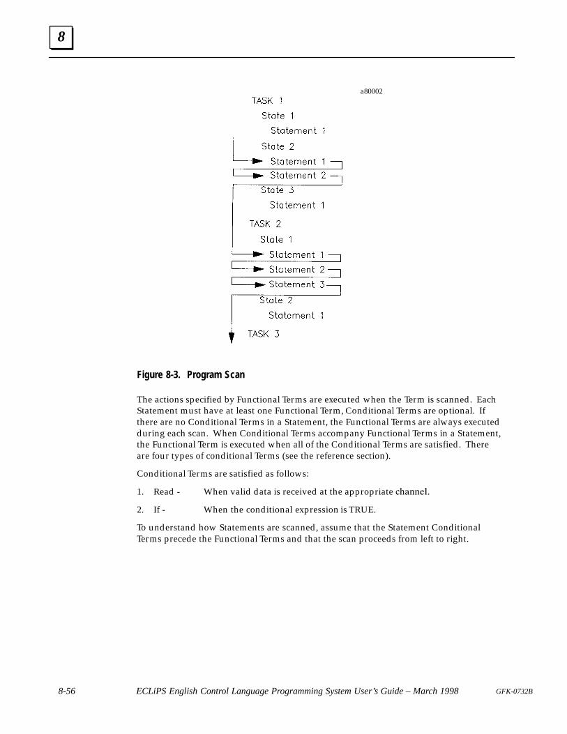
8
8-56 ECLiPS English Control Language Programming System User’s Guide – March 1998 GFK-0732B
a80002
Figure 8-3. Program Scan
The actions specified by Functional Terms are executed when the Term is scanned. EachStatement must have at least one Functional Term, Conditional Terms are optional. Ifthere are no Conditional Terms in a Statement, the Functional Terms are always executedduring each scan. When Conditional Terms accompany Functional Terms in a Statement,the Functional Term is executed when all of the Conditional Terms are satisfied. Thereare four types of conditional Terms (see the reference section).
Conditional Terms are satisfied as follows:
1. Read - When valid data is received at the appropriate ��������
2. If - When the conditional expression is TRUE.
To understand how Statements are scanned, assume that the Statement ConditionalTerms precede the Functional Terms and that the scan proceeds from left to right.

8
8-57GFK-0732B Chapter 8 Referemce
a80003
Figure 8-4. Statement Scan
The Statements of a State are executed in the order that they are written into the pro-gram. Functional Terms of Statements with no Conditional Terms are always executed.Conditional Terms in Statements control whether or not the Functional Terms in thoseStatements are executed. If all of the Conditional Terms are satisfied, the FunctionalTerms are executed. If any of the Conditional Terms are not satisfied, none of the Func-tional Terms are executed.
The Statements are executed one at a time. In this manner every Statement of the activeState is evaluated.
There are two types of Functional Terms that can prevent the execution of the rest of theStatements in a State. One is the Halt command which stops program execution. Theother is the “go to ...” command, which immediately causes another State to become theactive State.
For example:
If Start_Pushbutton is pushed, go to Start_Up State.Go to the Restart State.
causes the Start_Up State to become the active State when the process input representedby Start_Pushbutton is true. All Terms or Statements following this Statement are notexecuted and at the next controller cycle, the scan of this Task starts at the first Statementof the Start_Up State.

8
8-58 ECLiPS English Control Language Programming System User’s Guide – March 1998 GFK-0732B
Figure 8-5. Program Scan With GO Terms
Satisfied Conditional Term Unsatisfied Conditional Term Functional Term
Figure 8-6. Statement Scan With GO Terms
During the program scan any changes to variable and analog values are made immedi-ately. Therefore, a variable change in one Task is visible by the rest of the program dur-ing the same scan. On the other hand, digital I/O and Flag conditions are made at theend of the scan. Therefore, if one Task makes a change to the condition of a digital out-put or Flag, the condition cannot be tested by another Task until the next scan throughthe program.
8
8-59GFK-0732B Chapter 8 Referemce
Other State Engine Setup Options
Run-time Error SetupThe are several errors which may occur during execution of the State Logic programsuch as divide by zero or integer overflow or perform function errors. Run-time errorsare divided into critical and non-critical categories.
The default response of the State Engine is to halt the program when a critical error oc-curs and to continue program execution after a non-critical error. These responses maybe changed through options on the Debug Mode PROJECT menu.
Automatically Start Program ExecutionBy default the State Engine powers up in the Halted mode. The State Engine can be set-up to automatically start running the program when power comes on.
To set up the State Engine to automatically execute the program on power up, select the“State Engine Configuration” option from the Debug Mode PROJECT menu. When setto automatically run the program, the previous settings of other State Engine setup op-tions are also invoked on power up, including programming port, CCM Enables, CCMStation Number, Error Response Setup, and Simulation Mode Status.
Making a Permanent Copy of the Terminal LogThe Debug Mode main screen is called the Terminal Log. This log displays messagessent from the running control program, plus run-time error messages, and records of theuse of the FORCE, DISPLAY, and CHANGE functions. A time stamp accompanies all ofthese messages except for the information received from the running program.
The Terminal Log stores these messages so that even those messages that have scrolledoff the screen can be reviewed. To see information scrolled off the screen, press the uparrow key until to scroll the information back down into the screen. There is a limitedamount of space available, so that when there is no more storage space, the oldest in-formation is overwritten. When the Terminal Log storage space is full and the up arrowis continuously pressed, the information displayed eventually goes from the oldest backagain to the newest information.
To make a permanent record of the Terminal Log, select one of the Log options from theDebug Mode PROJECT menu. Using these options all of the information displayed inthe Terminal Log screen can be sent out the parallel printer port or entered into a diskfile. When either log is activated, an appropriate indication is displayed in the top bar ofthe screen.
Simulation ModeThe State Engine can be put in Simulation Mode through the option on the Debug ModePROJECT menu. When this mode is active the State Engine is completely disconnectedfrom the real world I/O; the State Engine does not change any outputs and does notlook at any of the inputs.
This mode is useful to debug a new program before connecting the I/O or for trouble-shooting a machine problem without interacting with I/O points. The State Engine set tothis mode executes the program.
8
8-60 ECLiPS English Control Language Programming System User’s Guide – March 1998 GFK-0732B
Make the program execute as desired by using the CHANGE option to change currentStates of the Tasks, variable values, and analog values. Use the FORCE option to changeI/O or flag status. Changes can also be made by using the VIEW option to display theEnglish program. Put the cursor on a name to display the current value then a new val-ue may be entered.
Setting the System ClockThe CPU has a clock that maintains the current month, day, day of the week, hour, min-ute, and second. These values are always available through the System Variables Month,Day, Day_of_Week, Hour, Minute, and Second.
The clock cannot be changed from the State Logic Processor. The time must be changedin the CPU using Logicmaster 90. After the time has been changed in the CPU and cyclepower to the system. The time is transferred from the CPU to the SLP on power up andat midnight.
ECLiPS Menu System
ECLiPS is a menu driven program with the Main Menu displayed when the program isstarted. The main menu offers five options:
Program ModeDebug ModeOnline ModifyingSetupQuit
Program ModeThe ECLiPS Program Mode is a highly specialized editor and compiler designed to createState Logic control programs for one of the Adatek State Engine controllers. This sectionexplains all of the menu selections available in the ECLiPS Program Mode.
The ECLiPS program includes the English text, the name definitions and system setupinformation. The English text is edited by the wordprocessing functions and other spe-cial functions are available to help enter some of the program text.
Another class functions define names used in the program to identify I/O points, vari-ables, Tasks, States, and elements of the control program. Still more functions are usedto specify system parameters such as security, scan control, and system setup options.
These functions are available through the Program Mode menu accessed by pressing<F3>. The following sections proceed through all of the menu options available in theProgram Mode, describing how to use each one.
AddAll of the ADD options are used to add program lines to the English text through the useof fill-in-the-blanks forms. The ADD options always enter text into the program. Thistext is no different from text entered from the keyboard and may be edited as other textis edited.
8
8-61GFK-0732B Chapter 8 Referemce
Add a New StateThis option prompts the user to enter a name for the new State followed by an optionalMax Time diagnostic value. The Max Time diagnostic displays a run-time message if theState is active longer than the specified time. If no the diagnostic is required for thisState, just hit <Enter> with no value specified in the Max Time entry window. The newState is inserted directly after the State where the cursor is located in the English text.
Add a New TaskThis option adds a new Task to the current program. ECLiPS asks if this Task shouldstart in the State that was active when the controller program was stopped. A prompt isdisplayed for the Max Time value for the PowerUp State of this Task. The new Taskname plus the PowerUp State name is inserted directly at the end of the Task where thecursor is located.
Add a State Time Out DiagnosticThis option adds the program text for a State Time Out Diagnostic. This option enters aStatement at the cursor location that transitions to another State in the event the Statehas been active for the specified amount of time. This time must be in the range of .01 to600.00 seconds.
Add an Analog Range Checking DiagnosticThis procedure works on any analog channel. Select an analog channel from the list andenter the high and low limits along with the State to branch to should the limit be ex-ceeded. When the form is completed, the ECLiPS enters the diagnostic instructions intothe program at the current cursor position. The English program instructions can beedited just as any other program Statements are edited.
Add a Variable Range Checking DiagnosticThe variable range checking diagnostic is identical to the analog range checking diagnos-tic except it checks variable values instead of analog values.
Add a “ Perform” FunctionThe Perform functions implement special purpose operations. ECLiPS automaticallyenters the English instructions for these functions from information entered in the pro-vided form. Perform functions are Functional Terms and must be the only Terms in theStatement. There may be an unlimited number of Perform functions in a State.
For a more detailed description of the perform functions see the Language Descriptionpart of the Reference Section of this manual.
ListThe List option is used to view and change lists of user defined names for I/O points,variables, PID Loops, Communication Ports, and Internal Flags. The predefined lists ofKeywords, Filler Words, Math Functions, PID Parameters and System Time Variables are
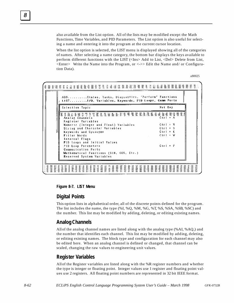
8
8-62 ECLiPS English Control Language Programming System User’s Guide – March 1998 GFK-0732B
also available from the List option. All of the lists may be modified except the MathFunctions, Time Variables, and PID Parameters. The List option is also useful for select-ing a name and entering it into the program at the current cursor location.
When the list option is selected, the LIST menu is displayed showing all of the categoriesof names. After selecting a name category, the bottom bar displays the keys available toperform different functions with the LIST (<Ins> Add to List, <Del> Delete from List,<Enter> Write the Name into the Program, or <->> Edit the Name and/or Configura-tion Data).
a80025
Figure 8-7. LIST Menu
Digital PointsThis option lists in alphabetical order, all of the discrete points defined for the program.The list includes the name, the type (%I, %Q, %M, %G, %T, %S, %SA, %SB, %SC) andthe number. This list may be modified by adding, deleting, or editing existing names.
Analog ChannelsAll of the analog channel names are listed along with the analog type (%AI, %AQ,) andthe number that identifies each channel. This list may be modified by adding, deleting,or editing existing names. The block type and configuration for each channel may alsobe edited here. When an analog channel is defined or changed, that channel can bescaled, changing the raw values to engineering unit values.
Register VariablesAll of the Register variables are listed along with the %R register numbers and whetherthe type is integer or floating point. Integer values use 1 register and floating point val-ues use 2 registers. All floating point numbers are represented in 32 bit IEEE format.
8
8-63GFK-0732B Chapter 8 Referemce
Numeric (Integer and Float) VariablesVariable names followed by the type are listed in alphabetical order. Integer variablesstore values in the range of -32,768 to +32,767. The range for floating point variables is+/- 1.175494E-38 to +/- 3.402823E+38.
String and Character VariablesString variables may be up to 100 characters in length and character variables store asingle character. The names are listed in alphabetical order along with the type. See thesection on the String Manipulation Perform Function for operations that can be per-formed on string variables.
Keywords and SynonymsAll of the words defined as keywords and their synonyms are listed with the defaultkeyword first followed by all of the synonyms of that keyword. From this display usethe following keys:
<Ins> - adds another synonym to the selected keyword���� � ��� � ���� �����
������ � ����� � ��� ���� � ������� �� � ������ ��������
���� � ��� � ���
���� � ���� � ���� ������� � �� ����� �����
Filler WordsA Filler word is one which is ignored by the ECLiPS translator. Filler words clarify themeaning of the control program. This list is managed by using the same keys that areused with the Keyword list.
Internal FlagsThe names of all of the flags are listed in alphabetical order. Flags are most often used tocommunicate between Tasks.
PID Loops and Initial ValuesThe names of all of the PID loops are listed in alphabetical order. Press <Enter> key toenter the PID name into the program. Other options also enter new PID loops or deletethe selected loop.
The most common use of this option is to enter the initial values of the PID parameters.When the right arrow key is pressed a form is provided to enter these values. See theLanguage Description section for a discussion of using PID loops.
PID Loop ParametersAll of the PID loop parameters are listed in alphabetical order. To use these parametersin a program, the parameter name follows the PID loop name. The programming line:
Make Tank_Temperature Gain equal to Second_Stage_Gain.
8
8-64 ECLiPS English Control Language Programming System User’s Guide – March 1998 GFK-0732B
assigns a new value to the gain parameter of the Tank_Temperature PID Loop.
Use this list to view the names of the PID Parameters or to enter the selected parameterinto the program ar the cursor location.
Communication PortsUse this option to change communication port names and parameters, to enter a Com-munications Port Name into the program at the current cursor location, or to enter aStatement into the program to change the serial port parameter settings.
The program Statement that changes the serial port parameters uses the Set_Commportkeyword. In order for the communications port parameters to be changed, the State-ment using the Set_Commport keyword must be executed by the program.
To enter the Statement to change the serial port parameters press the right arrow key toedit the parameters in a form. When finished press <Enter>, then select the “ Insert Re-configuration Data for Port” option. ECLiPS now enters the instructions into the pro-gram. Remember that just changing the parameter form does not change the port set-up, but the Set_Commport Statement must be executed in the program.
See the Control System Configuration part of the Reference Section for more informa-tion about the serial ports.
Mathematical FunctionsThe advanced mathematical functions are listed. Press <Enter> to write the functionname into the program at the cursor location. See the section on mathematical calcula-tions in the Reference section of this manual.
Reserved System Variable NamesThe time and date variables are listed. Use these time variables to access the systemclock. The clock can only be read using these variables in the program. To change theclock settings, use Logicmaster 90 to change the clock in the CPU, then cycle power inthe system.
DefineThese options are used the meaning of words used in the ECLiPS program and to speci-fy system configurations. Each of the options is described below.
The Current Word in the TextThis option displays the definition of the word at the cursor location. Use this choice isuseful when you are not sure what of a word’s definition. If the word is not defined,ECLiPS presents a list of possible definitions.
Undefined Words Throughout the TextThis option searches the entire program for undefined words. When one is found, theuser is given a list of possible types for the word. When a definition has been made, the
8
8-65GFK-0732B Chapter 8 Referemce
next undefined word is located and the process continues until the end of the text isreached.
PLC I/O, Analog, Digital, RegisterUse this option to define data elements, I/O points or Register Variables, that are storedin the CPU memory. Select the type to define and fill in the displayed form.
Series 90 Scan RatesThis option allows the programmer to customize the scanning of his analog channels.When analog channels are scaled, ECLiPS converts the raw analog values to floatingpoint numbers. Since floating point operations use a lot of time, the analog values andtheir conversion to floating point values are not updated every scan. Unscaled analogchannels are updated ever scan.
Use this option to change ECLiPS’ default analog scanning scheme. A form is providedto show how the analog channels are scanned. There are 8 columns and 10 rows. Theentry in each one of the 80 locations represents a block of 8 analog channels.
Each 1/10 of a second a collection of analog channels are scanned. The entries in eachrow represent the blocks of channels that are scanned for that 1/10 second time interval.There are 8 columns each representing a block of 8 channels, so that up to 84 analogchannels can be scanned every 1/10 second. If a block is to be scanned every interval or10 times a second, then that block must appear once in every row of the form.
There are 4 data entry locations at the top of the form. To enter values into the form, fillin these data entry locations for the Time Entry(Row), Block Entry(Column), Type andNumber. Item is entered into the form when the Number value is entered.
PID Loop Initial ValuesThe data entered in this form are the initial values given to the PID Loop when it isstarted under program control. See the section on PID Loops for more information onthese values.
Communication Port ConfigurationThe values entered in this form may be used to enter a communications port name orconfigure a communications port. See the Communications Port part of the System Con-figuration Section and the LIST option for more information about serial port configura-tion and use.
FindThese functions move the cursor around in the English text quickly and allow single andglobal replacements of text.
Find a Text StringThis function allows a user to enter any string of characters that may be present in theEnglish text. ECLiPS then begins searching forward through the English text from the
8
8-66 ECLiPS English Control Language Programming System User’s Guide – March 1998 GFK-0732B
current cursor location until the first occurrence is found. The cursor is then placed atthat position. If it is desired to search the entire file, the user may first press <Ctrl +Home> to go to the start of the program before using the FIND function.
Replace a Text String with Another
� �� �������� ������ � ��� �� ����� � ����� �������� �� � ���������� ������ ��� ���� �
�� � ������ �� � ����� �� ��� ������ � � � �������� ������ �� ���� �
������������ ��� �� ������ ���� � �������� ���� �����
Replace All Occurrences of a Text StringThis function replaces all occurrences of the entered string with the replacement stringwithout prompting the user for confirmation.
Perform the Next Find or ReplaceThis function uses the previously entered find and replacement strings. If no previousfind or replace has been initiated, this function executes as the Replace function de-scribed above.
Go to the Beginning of Another TaskThis function allows the user to enter the name of any Task. The cursor is then placed atthe start of that Task.
Go to the Last Project ErrorThis function places the cursor on the line where the last project error was found duringthe last Send or Check for Errors. After being placed at the occurrence of the error, theuser may move freely about the file. The error message is also displayed once again onthe bottom line of the screen.
ProjectThis menu contains project management functions needed to manipulate the files thatmake up a project. There are functions that act upon the entire project such as retrieveand save as well as functions to utilize portions of a project such as import.
Retrieve a Project from DiskThis function provides the user with a list of projects in the current working directoryfrom which to choose. After the selection, the cursor is placed in the editor at the begin-ning of the program.
Save Current Project to DiskThis function saves the project in the current working directory.

8
8-67GFK-0732B Chapter 8 Referemce
Copy the Current Project to a New OneThis function creates a copy of the current program including all name definitions andconfigurations. You give the new project a name and then there are two identical proj-ects with different names.
Note
To copy the current project be sure to use the copy option. Changingthe path and saving the project, copies only the current Task Group.
New Path/Drive for ProjectsThis function changes the current drive and or directory where. ECLiPS uses this driveand directory when saving and retrieving programs. Any valid drive and path may beentered.
ECLiPS creates several files when it processes the ECLiPS program. The filenames of thecreated files use the project name with several different extensions. These files arestored in the current directory. To move a project to another directory or another com-puter simply copy all of these files to the new location using DOS copying facilities.
Note
To copy the current project be sure to use the copy option. Changingthe path and saving the project, copies only the current Task Group.
Make a New ProjectThis function starts a new program. If there are unsaved changes from the current pro-gram, a prompt to save the program is displayed.
Import Data from Another ProjectThis function adds data from another project into the current one. Any of the followingcategories of data may be imported.
� All Project Sections - The entire project.
� Comm Port Configuration - This section contains Communication Port Configurationdata
� English Text - The program statements.
� PID Loop Configuration - This section contains the PID loop initial values andnames.
� Variable Names - This includes all variable names.
Print Project DataThis option allows the user to print any of the sets of information listed below.
� English text

8
8-68 ECLiPS English Control Language Programming System User’s Guide – March 1998 GFK-0732B
� I/O Map
� Data List
� Task/State List
� Cross Reference List
� CCM Protocol Listing
See the Creating Program Documentation section of this manual for more detailed in-formation on these categories.
The Header and Footer entered on this form will be stored on disk so they can be usedfor all print jobs. The “Output to : ” option directs the print data to the printer if theword printer is entered or to a file. To direct the output to a file just enter the file namefor this option.
Translate and Download Project to the ControllerUse this option to load the program into the State Engine through the programmingport. The program is saved to disk, checked for errors, translated and transmitted to theState Engine through the serial port.
To translate the program, ECLiPS creates a control program for the State Engine from theEnglish program. This translated program is saved in a file in the current directory andhas the project name with a .PSM extension. This option always causes the program tobe translated. If there have been no changes to the program since the last translation,use the Download only option to eliminate the translation step.
If the program has been changed since the last time it was saved, ECLiPS asks whetherto check for undefined words. Answer YES to have ECLiPS present all undefined wordsone at a time for definition. Answer NO to skip the undefined word search for a fasterdownload.
When a program is downloaded, it is automatically saved to disk and a backup of theprevious file with a .BK0 extension is created.
The download function always checks the program for errors. If an error is found, thecursor is placed at the line where the error occurred, and a message is provided with anexplanation of the error.
The program is sent out the current serial port. If ECLiPS cannot communicate to a StateEngine through the current serial port, an information panel is displayed presenting sev-eral options.
Select the “Try to Connect Again” option to attempt to connect to a State Engine again.Use this option to make another attempt to communicate with the State Engine, usuallyafter checking cable connections or powering up the State Engine.
Use the “Change Host Comm Port Settings” option, to change the current port to COM1or COM2 or to change the baud rate setting. After the change is saved, ECLiPS tries tocomplete the download operation.
Select the “Abandon Operation” option to stop the download operation and return tothe editor.
Error Check the Current ProjectThis function checks the project for errors, issuing a statistics report if there are no errors.If an error occurs, the cursor is placed at the line of the error and an error message is dis-

8
8-69GFK-0732B Chapter 8 Referemce
played. If no errors are found, a statistics report including data such as project size andnumber of Tasks and States will be displayed on the screen.
The Error Check causes the project to be saved and asks whether to check for undefinedwords. Also a translation is made and saved to disk. All the operations of a downloadare made except actually sending the translated program to the controller.
Translate ProjectThe translation is the changing of the English program to a format executable by theState Engine. This translated program is saved in a file in the current directory and hasthe project name with a .PSM extension. This options does all of the functions of the Er-ror Check but does not ask whether to check for undefined words.
Download Project to the ControllerThis option sends the current project to the State Engine without any new translations.Use this option when there have been no changes to the program since the last transla-tion. Eliminating the translation step saves time for the download. If there have beenchanges to the program since the last translation, an attempt to connect to the State En-gine after the download will result in an error message from the State Engine saying thatthe program on disk is more recent than the one in the controller. At this point the pro-gram must be translated first then downloaded again.
Delete the Project from DiskWhen this option is selected a list of all projects in the current directory except the cur-rent project are listed. Select the project to delete from the list and press <Enter>.
Make a New Task GroupUse this option to create a new Task Group. Initially the project is created all in one TaskGroup but for organizational reasons the project can be split into up to ten groups ofTasks.
Another reason to use more than one Task Group is that each Task Group is limited to64K characters including all spaces and comments. Therefore, if the English program isto take up more than 64K Bytes of memory space, more than one Task Group is required.
Enter the name of the new Task Group and first Task of the group when prompted to doso. When a project exists in more than one Task Group another option is displayed onthe Program Mode menu, “Task Group” , and this option no longer appears on the Proj-ect Menu.
TextThese are typical block manipulation functions found in most text editors. When thisoption is selected, the indicator word BLOCK is displayed in the top bar of the screen.ECLiPS is now ready for you to select a block of text for manipulation. Use the cursorkeys to highlight the block of text to be manipulated. The <Enter> key is used to com-plete the operation. The operation may also be terminated at any time by pressing<Esc>.

8
8-70 ECLiPS English Control Language Programming System User’s Guide – March 1998 GFK-0732B
Copy the Selected Block of TextThis function copies a selected block of text from one location to another point in thetext.
Move the Selected Block of TextThis function moves a selected block of text from one location to another point in thetext.
Remove the Selected Block of TextThis function removes a selected block of text permanently. It is possible, however toundo the last removal by pressing <Ctrl + U>.
Perform Multiple Copies of the Selected BlockThis function copies a selected block of text from one location any number of otherpoints in the text. Move the cursor to each location for another copy and press <Enter>.This operation is terminated by pressing <Esc>.
Task GroupThis menu option is displayed only when the project is split into more than one TaskGroup. The options offered on the Task Group Menu provide tools for managing thevarious Task Groups.
Make a New Task GroupThis option causes a new Task Group to be created. Enter the name of the new TaskGroup and the first Task name when instructed to do so.
Remove a Task GroupUse this option to delete a Task Group. Select the Task Group to delete from the list ofTask Groups displayed. When there is only one Task Group remaining, the ProgramMode menu no longer offers the Task Group option and the “Break Up the Project intoSeparate Task Groups” option is again displayed on the Project menu. The program textof the Task Group is erased but all of the definitions remain.
Give the Current Task Group a New NameThis option is used to change Task Group names. The name can be up to 20 characterslong.
Change the Order of the Task GroupsNormally the order of Tasks does not have any affect on the execution of the program.Digital outputs are not set until the end of the scan but variable values are changed im-
8
8-71GFK-0732B Chapter 8 Referemce
mediately, and changes to another Task’s current State are made immediately so that theorder that the Tasks are executed could make a difference to program results.
Use this option to change the order of execution of the Task Groups. Select the TaskGroup name from the list, and then enter the number to indicate the Task Group’s newposition in the list.
Join Two Task Groups TogetherUse this option to bring separate Task Groups together to form a single Task Group.When there is only one Task Group remaining, the Program Mode menu no longer of-fers the Task Group option and the “Break Up the Project into Separate Task Groups”option is again displayed on the Project menu.
Select the name of the Task Group from the list. The selected Task Group is then ap-pended to the end of the current Task Group.
Switch to Another Task GroupUse the option to change to another Task Group. Select the name of the Task Groupfrom the list displayed.
SecurityThis function allows the user to fill in a security table containing passwords for ECLiPSand the 4 access levels of OnTOP.
The password for ECLiPS covers access to the entire program, while each of the levelsfor OnTOP has a separate password. Level 4 provides unlimited access to all OnTOPfunctions. For each of the other levels of OnTOP security, select the functions they maybe accessed. The functions that may be selected are Force, Run, Halt, Change, Tune PIDLoops and Modify Monitor Tables.
Note: Each level of OnTOP security, must have a specified password. If ANY of thelevels does not have a password entered, then someone may gain access to OnTOP byjust pressing <ENTER> when asked for a password.
QuitLeave Program Mode and return to Main Menu.
Debug Mode
In debug mode ECLiPS communicates to the State Engine through the serial ports of thehost computer. All information sent to the controller is controlled and formatted byECLiPS and all data coming in from the controller is analyzed and manipulated prior tobeing displayed on the screen.
To enter the Debug Mode, the .PRJ and .TG0 files of the project loaded in the State En-gine must be in the current directory of the ECLiPS host computer. If these files have adifferent date/time stamp from the program in the State Engine, ECLiPS issues an errormessage and denies access to the Debug Mode.
8
8-72 ECLiPS English Control Language Programming System User’s Guide – March 1998 GFK-0732B
Before starting the Debug Mode, ECLiPS compares the date and time of the last changesthe program with the date and time of the program in the controller. If the program inthe controller is not the same version as the one in ECLiPS, an error message is dis-played. The version of the program used by ECLiPS must match the version of the onein the controller.
There is a menu system for interacting with the State Engine with the program runningor halted. The following sections describe each of the menu options.
ProjectThese functions are used to manage the State Logic Processor, manage program execu-tion (start or stop or simulation mode), manage serial ports and logs, change SLP config-uration, and download a new program.
Run Program in the Controller
�� ����� � ���� �� �� ������� �� �� �����
Halt Program in the Controller
This command halts the program in the controller immediately without any prompt.
Communication Port Reset
The communication port may become disabled by improper data transfer or noise on theserial cable so this function is available to reset the port and restore communicationswith the controller.
Start Printer Output
This function allows the user to send all of the data, that is displayed in the terminal log,out to a printer attached to the parallel port (LPT1). When the printer log is active, theword PRINT appears in the top bar of the screen. If there is a printer error, the printerlog is no longer active and an error message is displayed. To stop the printer log selectthat option from the menu.
Activate Log File Output
This function allows the data sent to the terminal log to also be sent to a disk file with auser given name of up to 8 characters. The log file name is given an extension of .LOG.The log file is limited in size to 100K bytes. When the file size reaches 100k the loggingof data is terminated.
State Engine Configuration
This option is used to setup the State Engine. Several setup options are displayed on thefollowing form. This form shows current conditions and provided a space to makechanges.
Toggle Simulation Mode
When the State Engine is in Simulation Mode, it does not communicate with the I/O.The State Engine does execute its program, but there is no transfer of inputs or outputs.
8
8-73GFK-0732B Chapter 8 Referemce
To test a program in Simulation Mode, digital I/O and flags may be forced and analogvariable values may be changed. The current State of a Task may also be changed.
To change to normal mode with the I/O System enabled, choose this option again. Thisoption may not be chosen when the State Engine is executing a program.
Enable/Disable CCM Protocol Port
The CCM port is the one not designated to be the programming port. When enabled,the CCM port responds to commands using the CCM protocol. The default state of theCCM port is disabled. See the Series 90-30 State Logic Control System section of thismanual for more information of the serial ports.
CCM Port Number
Selects which serial port to be the CCM port. This port cannot be the same as theprogramming port.
Set CCM Protocol Station Address
Setting the CCM station number for the State Engine, gives the State Engine a number inthe range 1 - 89. The State Engine then only responds to commands using the specifiedstation address.
Enable/Disable Automatic Program Execution on Power Up
The default SLP response to power up is to be in halt mode. If automatic execution isenabled, the program starts running automatically when power is applied to the system.The SLP configurations active when power was lost are still active when automaticexecution is enabled. These options include serial port setups, error handling configura-tion, CCM setup, and programming port designation.
Error Handling Setup
There are two classes of run-time errors generated by the State Engine; critical and non-critical. This option allows the State Engine to be configured to either halt the programor continue running when an error in either one of these two classes occurs.
When this option is chosen, the first the response to critical and next to non-critical er-rors is chosen. This setup may be changed at any time.
Change Programming Port
This option allows serial port chosen to be the programming port to be changed. Theprogramming port is the one that connects the State Engine to ECLiPS. The default pro-gramming port is port 1. The programming port cannot be the same port as the CCMPort.
Enter the number of the port that is the new programming port. If the programmingport is changed, the current connection between the State Engine and ECLiPS is no long-er valid. ECLiPS must now be connected to the new port.
Download Project to the Controller
Use this option to download a new program to the State Engine. First the option to se-lect a new directory is presented and then a list of projects from the current directory.
8
8-74 ECLiPS English Control Language Programming System User’s Guide – March 1998 GFK-0732B
Select the project top be downloaded to the controller. A new project cannot be down-loaded when the program is running. When the program is running, ECLiPS askswhether to stop the program or cancel the download.
Reset and Clear the State Engine
Use this option to clear the State Engine program memory and return all configurationparameters to the default condition. The State Engine setup options returned to theirdefault state are CCM port setup, error handling setup, programming port selection, andautomatic run setup.
MonitorMonitor is an on-going display of the current values of all the selected elements. Up to 6elements may be included in a monitor table at any time and up to 10 monitor tablesmay be defined. Monitor tables have user given names of up to 30 characters each.Spaces can be part of a Monitor Table name.
Enable Display
This function activates the display of the monitor tables. While a table is displayed, theuser may press <Tab> to switch to the next table. If there are no tables defined, the userwill be prompted to add a new one.
Disable Display
This function disables the monitor display but the tables are saved for the next time theyare needed.
Add a New Monitor Table
This function allows the user to add a new monitor table as long as there are currentlyless than 10. It acts the same way as Monitor Setup. If no name is given to the table, itwill default to “Number X” where X is a number between 1 and 10 corresponding withthe position in the list of tables.
Select a Monitor Table
This function will display a list of the available monitor tables and allow the user to selectone. The selected table will then become active in the monitor window.
Modify the Current Monitor Table
This allows a user to add and remove elements from the current monitor table. The listbelow shows the types of elements that may be monitored.
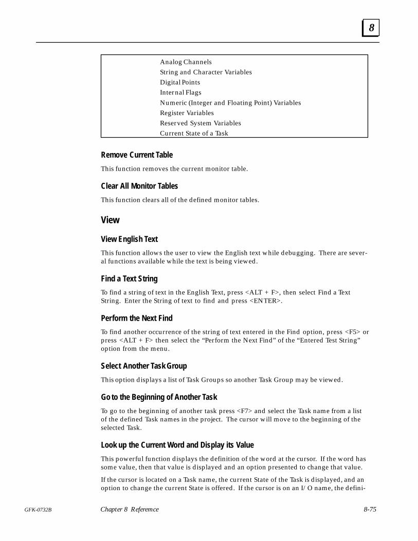
8
8-75GFK-0732B Chapter 8 Referemce
Analog Channels String and Character Variables Digital Points Internal Flags Numeric (Integer and Floating Point) Variables Register Variables Reserved System Variables Current State of a Task
Remove Current Table
This function removes the current monitor table.
Clear All Monitor Tables
This function clears all of the defined monitor tables.
View
View English Text
This function allows the user to view the English text while debugging. There are sever-al functions available while the text is being viewed.
Find a Text String
To find a string of text in the English Text, press <ALT + F>, then select Find a TextString. Enter the String of text to find and press <ENTER>.
Perform the Next Find
To find another occurrence of the string of text entered in the Find option, press <F5> orpress <ALT + F> then select the “Perform the Next Find” of the “Entered Test String”option from the menu.
Select Another Task Group
This option displays a list of Task Groups so another Task Group may be viewed.
Go to the Beginning of Another Task
To go to the beginning of another task press <F7> and select the Task name from a listof the defined Task names in the project. The cursor will move to the beginning of theselected Task.
Look up the Current Word and Display its Value
This powerful function displays the definition of the word at the cursor. If the word hassome value, then that value is displayed and an option presented to change that value.
If the cursor is located on a Task name, the current State of the Task is displayed, and anoption to change the current State is offered. If the cursor is on an I/O name, the defini-
8
8-76 ECLiPS English Control Language Programming System User’s Guide – March 1998 GFK-0732B
tion is displayed, and from the window the current value can be forced to another value.Similarly, variable definitions are displayed and options presented to change those val-ues.
Current State of Each Task
This function displays the active State of every Task. The display is updated twice persecond providing a realistic view of the current status of the process. Each Task name isdisplayed, followed by its current State.
View Event Queue
The Event Queue includes time stamped data about the Controller such as Run, Halt,Power Up, Power Down, Critical Run-Time Errors, etc. The user may view up to the last64 entries with 6 being the default number to view.
View System Status
This includes system date, time, memory usage and current scan rates in milliseconds.The scan rate information specifies the average scan rates for the last 1000 scans. Thescan is also split into the time for State Logic to be scanned and the time for the transferof I/O data between the SLP and CPU.
TraceThe Trace is a collection of the most recent program State transitions. This option allowsthe user to display the history of State transitions on the screen for all Tasks or selectedTasks.
Upload Trace from the Controller
This function will upload the Trace data from the controller and display it for the user tobrowse through. The Trace is also stored in a file on the logged disk and directory sothat it may be viewed at a later time. Each upload of the Trace information, overwritesthe previous upload saved to disk. The Trace is stored in a file with the project name anda .TRC extension, for example: CONVEYOR.TRC.
The display shows each State transition, listing the starting State, the resulting State andthe time of the transition. The most recent transition is at the top of the list.
There are string search functions available to help find a specific State transition. Press<ALT + F> to access these search functions. Also the up and down arrows and <PgUp> and <Pg Dn> keys are used to move through the listing.
Display the Previously Uploaded Trace
�� �� ��� ����� � � ������� �� ��� �� �� ������� ����� ������ �� � ������ �
����
Setup Trace List
This option allows the user to setup the Tasks that will be traced (stored in the Trace buff-er). Upon entering this function, a list of the currently traced Tasks will be displayed andthe user may add or delete Tasks.
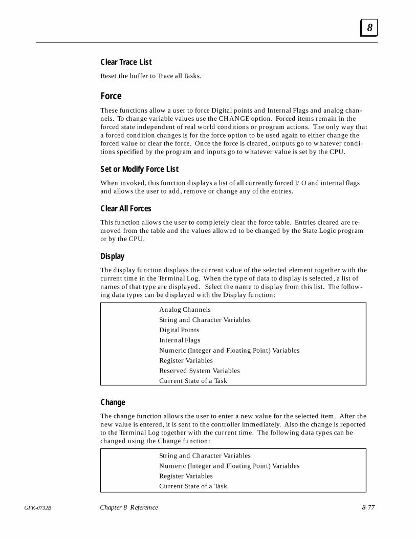
8
8-77GFK-0732B Chapter 8 Referemce
Clear Trace List
Reset the buffer to Trace all Tasks.
ForceThese functions allow a user to force Digital points and Internal Flags and analog chan-nels. To change variable values use the CHANGE option. Forced items remain in theforced state independent of real world conditions or program actions. The only way thata forced condition changes is for the force option to be used again to either change theforced value or clear the force. Once the force is cleared, outputs go to whatever condi-tions specified by the program and inputs go to whatever value is set by the CPU.
Set or Modify Force List
When invoked, this function displays a list of all currently forced I/O and internal flagsand allows the user to add, remove or change any of the entries.
Clear All Forces
This function allows the user to completely clear the force table. Entries cleared are re-moved from the table and the values allowed to be changed by the State Logic programor by the CPU.
Display
The display function displays the current value of the selected element together with thecurrent time in the Terminal Log. When the type of data to display is selected, a list ofnames of that type are displayed. Select the name to display from this list. The follow-ing data types can be displayed with the Display function:
Analog Channels String and Character Variables Digital Points Internal Flags Numeric (Integer and Floating Point) Variables Register Variables Reserved System Variables
Current State of a Task
Change
The change function allows the user to enter a new value for the selected item. After thenew value is entered, it is sent to the controller immediately. Also the change is reportedto the Terminal Log together with the current time. The following data types can bechanged using the Change function:
String and Character VariablesNumeric (Integer and Floating Point) Variables
Register Variables Current State of a Task
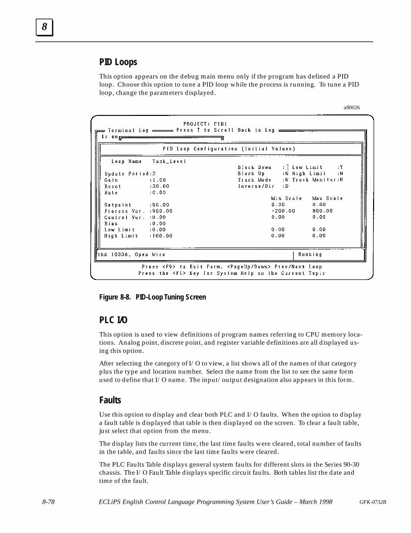
8
8-78 ECLiPS English Control Language Programming System User’s Guide – March 1998 GFK-0732B
PID LoopsThis option appears on the debug main menu only if the program has defined a PIDloop. Choose this option to tune a PID loop while the process is running. To tune a PIDloop, change the parameters displayed.
a80026
Figure 8-8. PID-Loop Tuning Screen
PLC I/OThis option is used to view definitions of program names referring to CPU memory loca-tions. Analog point, discrete point, and register variable definitions are all displayed us-ing this option.
After selecting the category of I/O to view, a list shows all of the names of that categoryplus the type and location number. Select the name from the list to see the same formused to define that I/O name. The input/output designation also appears in this form.
FaultsUse this option to display and clear both PLC and I/O faults. When the option to displaya fault table is displayed that table is then displayed on the screen. To clear a fault table,just select that option from the menu.
The display lists the current time, the last time faults were cleared, total number of faultsin the table, and faults since the last time faults were cleared.
The PLC Faults Table displays general system faults for different slots in the Series 90-30chassis. The I/O Fault Table displays specific circuit faults. Both tables list the date andtime of the fault.
8
8-79GFK-0732B Chapter 8 Referemce
QuitLeave Debug Mode and return to the Main Menu.
Online Modify
The Online Modify option is used to change the program without halting programexecution. One Task of the program is changed at a time. When the Task changes arecomplete, ECLiPS translates the entire project, checking for any programming errors.The State that is to be active when the changed Task starts executing is specified andthen the changed Task is downloaded. The changed Task replaces the old one at the startof the first scan after the Task is downloaded.
Modify Mode Menu OptionsThe programmer is can change the project while the program is running using most ofthe same menu options available in Program Mode. The dfferences in the menu optionsoffered in Modify Mode reflect the editing limitations for this mode.
• One Task is modified at a time.• No discrete, analog l/O, or Register Variables may be added or changed.• States may be added or deleted, but the number of States in the modified Task is
limited to 2 more than the number of States in the largest Task of the project.• Variables may be added but not made retentive, and existing variables may not be
changed or deleted.
Onllne Modify Restrictions
Online Modify Menu Differences from Program Mode
ADD - The changes in the ADD menu from Program Mode are that Taskscannot be added and the State Timeout Diagnostic is not available.
LIST - The LIST menu is the same for both Program and Modify Modes, butthere are some restrictions limiting changes and additions for l/O andvariables.
DEFINE - The Modify Mode DEFINE menu does not allow new l/O to be definedand the PLC l/O Scan Rate option which specifies how often analog l/Oare scanned is not available.
FIND - All of the options from the Program Mode FIND menu are offered in Modify Mode except the option to find the start of another Task.
PROJECT - The only 2 options on the Modify Mode PROJECT menu are Translateand Download and just Translate. The Translate Only option does anerror check an then transfers to the Debug Mode. The Task changesmade in Modify Mode are not loaded into the controller. These changesare not abandoned yet. When the QUIT option is selected from theDEBUG menu, ECLiPS asks whether to return to Online Editing orabandon the changes.
TEXT - The TEXT options are identical to the Program Mode options.

8
8-80 ECLiPS English Control Language Programming System User’s Guide – March 1998 GFK-0732B
SECURITY - There is no SECURITY option on the Modify Mode menu.
QUIT - The QUIT option returns to the Main Menu.
Setup and ECLiPS Memory Usage
The setup option is used to configure the ECLiPS system. The two options that can beselected are the maximum number of defined data elements (Discrete l/O, Flags, Analogl/O, and Variables) to be used in the project and the maximum number of States in theproject. The number of data elements is may be from 500 to 3000 in increments of 500.The number of States is 500 to 3000 in increments of 500.
The maximum limits cannot be selected for both the number of States and number ofNames for I/O and variables. The maximum total number for States plus names is 4500.If the ECLiPS computer does not have enough memory for the selected limits, ECLiPSdisplays an error message and allows the Setup limits to be reselected.
There are two reasons to select smaller than maximum size limits for the ECLiPS setupoptions. First ECLiPS requires less free conventional memory with lower defined limits.The second reason is that ECLiPS uses a page swapping system and therefore does someoperations faster when using the smaller limits.
If there is not enough conventional memory available to load ECLiPS, the Setup screen isdisplayed to reconfigure ECLiPS for a smaller number of States and/or variables. Afterthese quantities are changed, ECLiPS is restarted. Another way to deal with the problemof not enough memory to run ECLiPS, is to free up conventional memory in your PC byeliminating device drivers and Terminate and Stay Resident (TSR) programs bychanging your CONFIG.SYS and AUTOEXEC.BAT files. If you are using DOS 5.x,loading DOS HIGH also frees up additional conventional memory. To use the maximumsettings for the number of States and Variables, DOS must be loaded into high memoryarea.
ECLiPS also makes use of Expanded and Extended memory if they are available withappropriate memory managers installed. By using Expanded and/or Extended memory,ECLiPS can be configured for more States and Variables and also executes faster. TheExpanded memory and memory manager must be version LIM 3.2 or higher, and theExtended memory and memory manager must be version XMS 2.0 or higher.
EMM386.SYS can be used for Expanded memory and HIMEM.SYS can be used forExtended memory. One megabyte of added memory is enough to provide themaximum capacity and speed for ECLiPS operations.
Quit
Use this option to exit ECLiPS and return to DOS.
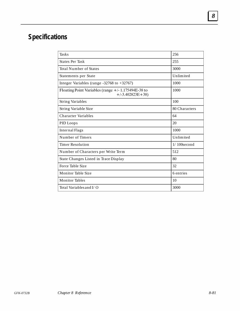
8
8-81GFK-0732B Chapter 8 Referemce
Specifications
Tasks 256
States Per Task 255
Total Number of States 3000
Statements per State Unlimited
Integer Variables (range -32768 to +32767) 1000
�������� ����� ��������� ������ ��� ��� ������� �������������
1000
String Variables 100
String Variable Size 80 Characters
Character Variables 64
PID Loops 20
Internal Flags 1000
Number of Timers Unlimited
Timer Resolution 1/100 second
Number of Characters per Write Term 512
State Changes Listed in Trace Display 80
Force Table Size 32
Monitor Table Size 6 entries
Monitor Tables 10
Total Variables and I/O 3000
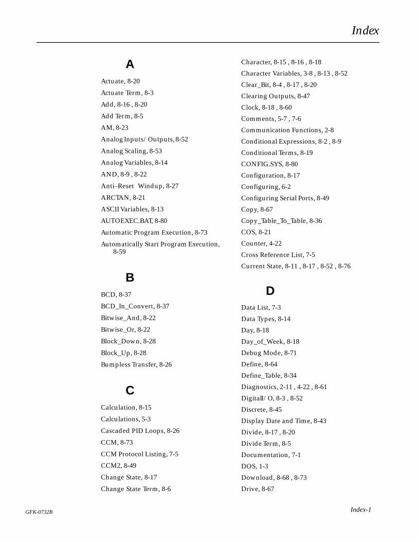
Index
Index-1GFK-0732B
AActuate, 8-20
Actuate Term, 8-3
Add, 8-16 , 8-20
Add Term, 8-5
AM, 8-23
Analog Inputs/Outputs, 8-52
Analog Scaling, 8-53
Analog Variables, 8-14
AND, 8-9 , 8-22
Anti–Reset Windup, 8-27
ARCTAN, 8-21
ASCII Variables, 8-13
AUTOEXEC.BAT, 8-80
Automatic Program Execution, 8-73
Automatically Start Program Execution,8-59
BBCD, 8-37
BCD_In_Convert, 8-37
Bitwise_And, 8-22
Bitwise_Or, 8-22
Block_Down, 8-28
Block_Up, 8-28
Bumpless Transfer, 8-26
CCalculation, 8-15
Calculations, 5-3
Cascaded PID Loops, 8-26
CCM, 8-73
CCM Protocol Listing, 7-5
CCM2, 8-49
Change State, 8-17
Change State Term, 8-6
Character, 8-15 , 8-16 , 8-18
Character Variables, 3-8 , 8-13 , 8-52
Clear_Bit, 8-4 , 8-17 , 8-20
Clearing Outputs, 8-47
Clock, 8-18 , 8-60
Comments, 5-7 , 7-6
Communication Functions, 2-8
Conditional Expressions, 8-2 , 8-9
Conditional Terms, 8-19
CONFIG.SYS, 8-80
Configuration, 8-17
Configuring, 6-2
Configuring Serial Ports, 8-49
Copy, 8-67
Copy_Table_To_Table, 8-36
COS, 8-21
Counter, 4-22
Cross Reference List, 7-5
Current State, 8-11 , 8-17 , 8-52 , 8-76
DData List, 7-3
Data Types, 8-14
Day, 8-18
Day_of_Week, 8-18
Debug Mode, 8-71
Define, 8-64
Define_Table, 8-34
Diagnostics, 2-11 , 4-22 , 8-61
Digital I/O, 8-3 , 8-52
Discrete, 8-45
Display Date and Time, 8-43
Divide, 8-17 , 8-20
Divide Term, 8-5
Documentation, 7-1
DOS, 1-3
Download, 8-68 , 8-73
Drive, 8-67
Index
Index-2 GFK-0732B
EECLiPS Memory, 8-80
Energize, 8-20
English Code, 7-2
Error, 6-5 , 8-73
Error Setup, 8-59
Event Queue, 8-76
EXP, 8-21
Expanded Memory, 1-3 , 8-80
Expressions, 8-2
FFaults, 6-7 , 8-78
File, 8-59
Filler Words, 3-6 , 8-24 , 8-63
Find, 8-65
Finite States, 2-2
Flag, 3-8
Flags, 8-3 , 8-52 , 8-63
Floating Point, 8-14
Floating Point Variables, 3-8 , 8-52
For, 8-19
Force, 6-7 , 8-77
Formatting, 8-8
Friday, 8-23
FROM, 8-12 , 8-23
Function Key Definitions, 8-44
Functional Expressions, 8-2 , 8-3 , 8-16
Functional Terms, 8-20
GGet User Input, 8-43
GO, 8-12 , 8-18 , 8-20
GO Term, 8-6
HHALT, 6-5 , 8-20
Hardware Requirements, 1-3
Hot Keys, 5-11 , 8-44
Hour, 8-18
II/O Map, 7-2
If, 8-9 , 8-19
Import, 8-67
Inactive, 8-23
Inactive State, 8-6
INIT–30.SDE, 8-47
Initialization, 6-3
Initializing Tables, 8-35
Input, 8-46
Installation, 1-3
Integer, 8-14
Integer Variables, 3-7 , 8-14 , 8-52
KKeyboard Definitions, 8-44
Keywords, 3-6 , 8-1 , 8-19 , 8-63
LLanguage Structure, 8-2
Lists, 5-12 , 8-61
LN, 8-21
Log, 6-4 , 8-59
Log File, 8-72
Logicmaster 90, 8-48
MMake, 8-20
Make Term, 8-4 , 8-16
Mathematical Calculations, 8-13
Index
Index-3GFK-0732B
Mathematical Operators, 8-21
Max_Time, 8-23
Memory Capacities, 8-47
Menus, 5-11
Minute, 8-18
Modulus, 8-21
Monday, 8-23
Monitor, 6-5 , 8-74
Month, 8-18
Multiply, 8-16 , 8-20
Multiply Term, 8-5
NNames, 3-4 , 5-6
NOT, 8-9 , 8-22 , 8-23
Numeric Variables, 8-14
OOff, 8-23
On, 8-23
Online Modify, 8-79
OR, 8-9 , 8-22 , 8-23
Output, 8-46
Output_BCD_Convert, 8-38
PPath, 8-67
Perform, 8-18 , 8-20
Perform Functions, 8-9 , 8-17 , 8-32 , 8-61
PID Command and Status Bits, 8-30
PID Inputs, 8-30
PID Loop Parameters, 8-52
PID Loops, 6-7 , 8-8 , 8-17 , 8-24 , 8-63 ,8-78
PID Output, 8-31
PID Parameters, 8-29
PID Value, 8-15 , 8-18
PM, 8-24
Power Up, 8-47
Precedence, 8-13
Print, 7-1 , 8-67
Printer, 8-72
Program Mode, 8-60
Programming Port, 8-49 , 8-73
RR_Register, 8-7 , 8-24
R_Register Variables, 8-14
RANDOM, 8-21
READ, 4-21 , 5-4 , 8-12 , 8-18 , 8-19
Register, 8-45
Register Variables, 3-8 , 8-62
Relational Operators, 8-22
Relational Terms, 8-11
Replace, 8-66
Restart_In_Last_State, 8-3 , 8-24
Resume_Task, 8-6 , 8-21
Retrieve, 8-66
RS–232, 8-49
RUN, 6-5
SSaturday, 8-24
Save, 8-66
Scan, 2-9 , 3-8 , 5-7 , 8-54
Second, 8-18
Seconds, 8-24
Security, 8-71
Serial Data, 8-17
Serial Ports, 8-7 , 8-49
Series 90 Scan Rates, 8-65
Set_Bit, 8-4 , 8-17 , 8-20
Set_Commport, 8-8 , 8-13 , 8-17 , 8-20
Setup, 8-48 , 8-80
Shift_Register, 8-39
Index
Index-4 GFK-0732B
Simulation Mode, 6-5 , 8-59 , 8-72
SIN, 8-21
SLP/CPU Interface, 8-45
Specifications, 8-81
SQRT, 8-21
Start_PID, 8-17 , 8-20
State Engine Configuration, 8-59 , 8-72
State Logic Control Theory, 2-1
STATEMENTS, 2-4 , 2-7 , 3-3 , 3-5 , 8-1 , 8-2, 8-3
STATES, 2-2 , 2-4 , 2-6 , 3-2 , 4-3 , 8-1 , 8-3 ,8-6 , 8-11 , 8-18 , 8-20 , 8-61
Stop_PID, 8-17 , 8-20
String, 8-15 , 8-16 , 8-18
String Manipulation, 8-40
String Variable, 8-13
String Variables, 3-8 , 8-52
Subtract, 8-16 , 8-20
Subtract Term, 8-5
Sunday, 8-24
Suspend_Task, 8-6 , 8-21
Swap_Table_Value, 8-34
Synonyms, 3-6
System Clock, 8-18 , 8-60
TTable, 8-33
TAN, 8-21
Task Group, 8-69 , 8-70
Task/State List, 7-4
TASKS, 2-3 , 2-4 , 2-5 , 2-9 , 3-2 , 4-3 , 5-3 ,8-1 , 8-3 , 8-6 , 8-11 , 8-18 , 8-20 , 8-61
Tasks, 2-4
Technical Support, 1-4
Terminal Log, 8-59
Text String, 8-65 , 8-75
Thursday, 8-24
Time Counter, 8-42
Time Variables, 3-8 , 8-14 , 8-18
Timer, 5-5 , 8-10 , 8-17
Trace, 6-7 , 8-76
Track_Mode, 8-27
Translate, 8-68
Tuesday, 8-24
Tuning, 8-28
UUnderscores, 5-6
UNINSTALL, 1-3
User Menu, 8-43
VVariables, 3-7 , 8-63
View, 6-6 , 8-75
WWait, 8-19
Wednesday, 8-24
With, 8-24
Write, 4-21 , 8-21
Write Term, 5-2 , 8-7