
GEYSAIRADDENDum owNER’ S mANu Al - · PDF fileremote mounting 20 tHe ... Horizontal...
24
GEYSAIR TM ADDENDUM to the OWNER’S MANUAL IMPORTANT INFORMATION FOR THE INSTALLER AND THE OWNER INCLUDED: THERMOMASSEUR ® WITH GEYSAIR TM INSTALLATION IMPORTANT: TO BE KEPT FOR THE OWNER
Transcript of GEYSAIRADDENDum owNER’ S mANu Al - · PDF fileremote mounting 20 tHe ... Horizontal...
GEYSAIRTM ADDENDum to the owNER’S mANuAlIMporTanT InforMaTIon for The InsTaller and The owner
INcluDED: TherMoMasseur® wITh GeysaIrTM InsTallaTIon
Imp
oR
tAN
t: t
o b
E k
Ep
t f
oR
th
E o
wN
ER

geysairtm addendum to the owner’s manual
3 www.bainultra.com
Printed in Canada. Copyright © september 2012 Bainultra inc. all rights reserved. 45100169some products, specifications, and services mentioned in this manual are described in pending patent applications or are protected by patents.
table of contents
safety instructions 4
tHerMoMasseur®
ayoura® freestanding 5
amma® freestanding 6
Balneo® - naos & sanos - installation 7 - 8
Balneo® - Cella - installation 9
origami freestanding installation 10 - 11
essenCia oval 7236 - Parts and tools - installation 12 - 13
essenCia reCtangular 6838 - Parts and tools - installation 14 - 15
turBine
teChniCal sPeCifiCations 16
eleCtriCal installation & PlumBing 17 - 19
remote mounting 20
tHe Mia® series controls
miaPlus - user guide 21 - 22
trouBlesHooting 23
warranty 24
956, chemin oliviersaint-nicolas (Québec)g7a 2n1
t 418.831.7701 1.800.463.2187
f 418.831.6623 1.800.382.8587 [email protected]
4 supercede page 4 of owner’s Manual
geysairtm addendum to the owner’s manual | SAFETY INSTRUCTIONS
InstRUctIons PeRtaInInG to a RIsK of fIRe, electRocUtIon, oR PeRsonal InJURY
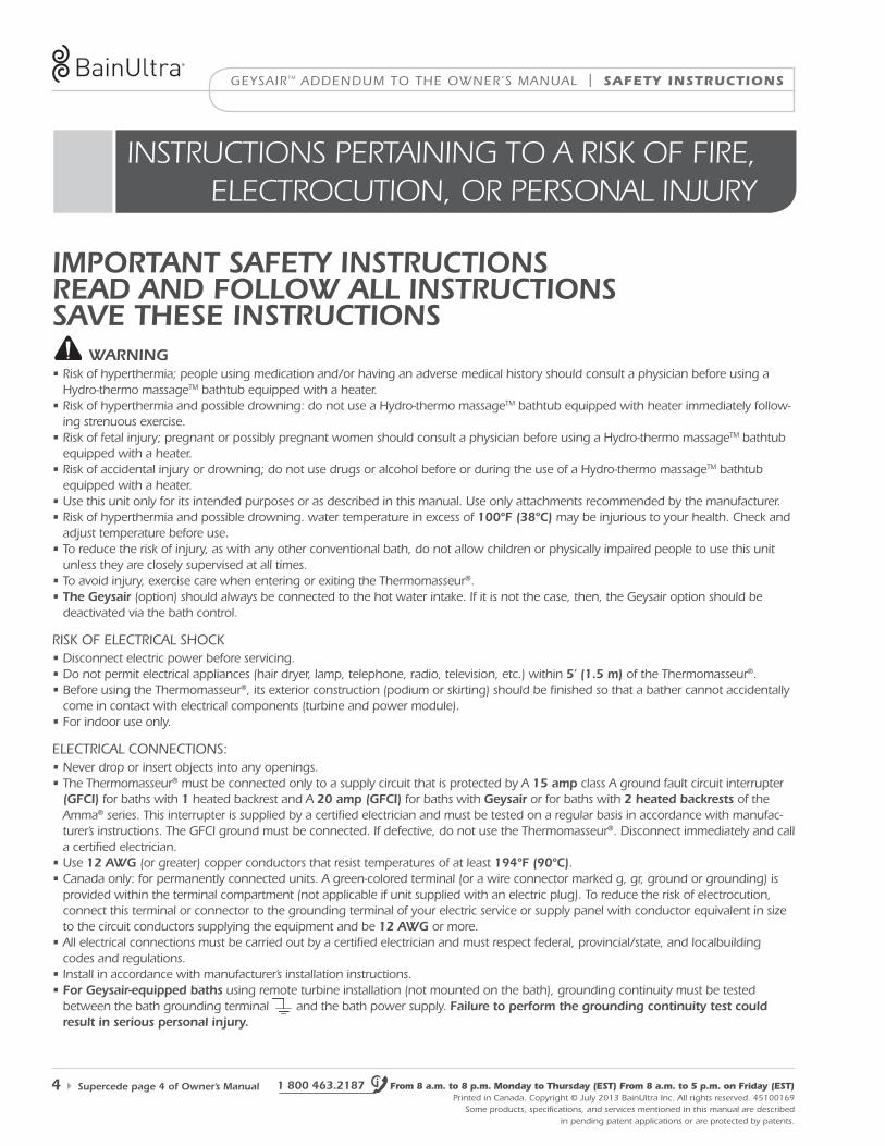
iMportant safety instructionsreaD anD follow all instructionssaVe tHese instructions
• risk of hyperthermia; people using medication and/or having an adverse medical history should consult a physician before using a hydro-thermo massagetm bathtub equipped with a heater.
• risk of hyperthermia and possible drowning: do not use a hydro-thermo massagetm bathtub equipped with heater immediately follow-ing strenuous exercise.
• risk of fetal injury; pregnant or possibly pregnant women should consult a physician before using a hydro-thermo massagetm bathtub equipped with a heater.
• risk of accidental injury or drowning; do not use drugs or alcohol before or during the use of a hydro-thermo massagetm bathtub equipped with a heater.
• use this unit only for its intended purposes or as described in this manual. use only attachments recommended by the manufacturer.• risk of hyperthermia and possible drowning. water temperature in excess of 100ºf (38ºc) may be injurious to your health. Check and
adjust temperature before use.• to reduce the risk of injury, as with any other conventional bath, do not allow children or physically impaired people to use this unit
unless they are closely supervised at all times. • to avoid injury, exercise care when entering or exiting the thermomasseur®.• the geysair (option) should always be connected to the hot water intake. if it is not the case, then, the geysair option should be
deactivated via the bath control.
risK of eleCtriCal shoCK• disconnect electric power before servicing.• do not permit electrical appliances (hair dryer, lamp, telephone, radio, television, etc.) within 5’ (1.5 m) of the thermomasseur®.• Before using the thermomasseur®, its exterior construction (podium or skirting) should be finished so that a bather cannot accidentally
come in contact with electrical components (turbine and power module).• for indoor use only.
eleCtriCal ConneCtions:• never drop or insert objects into any openings.• the thermomasseur® must be connected only to a supply circuit that is protected by a 15 amp class a ground fault circuit interrupter
(gfci) for baths with 1 heated backrest and a 20 amp (gfci) for baths with geysair or for baths with 2 heated backrests of the amma® series. this interrupter is supplied by a certified electrician and must be tested on a regular basis in accordance with manufac-turer’s instructions. the gfCi ground must be connected. if defective, do not use the thermomasseur®. disconnect immediately and call a certified electrician.
• use 12 awg (or greater) copper conductors that resist temperatures of at least 194ºf (90ºc).• Canada only: for permanently connected units. a green-colored terminal (or a wire connector marked g, gr, ground or grounding) is
provided within the terminal compartment (not applicable if unit supplied with an electric plug). to reduce the risk of electrocution, connect this terminal or connector to the grounding terminal of your electric service or supply panel with conductor equivalent in size to the circuit conductors supplying the equipment and be 12 awg or more.
• all electrical connections must be carried out by a certified electrician and must respect federal, provincial/state, and localbuilding codes and regulations.
• install in accordance with manufacturer’s installation instructions.• for geysair-equipped baths using remote turbine installation (not mounted on the bath), grounding continuity must be tested
between the bath grounding terminal and the bath power supply. failure to perform the grounding continuity test could result in serious personal injury.
warning
1 800 463.2187 From 8 a.m. to 8 p.m. Monday to Thursday (EST) From 8 a.m. to 5 p.m. on Friday (EST) Printed in Canada. Copyright © July 2013 Bainultra inc. all rights reserved. 45100169
some products, specifications, and services mentioned in this manual are described in pending patent applications or are protected by patents.
tHERMOMASSEUR® | geysairtm addendum to the owner’s manual
www.bainultra.com Printed in Canada. Copyright © July 2013 Bainultra inc. all rights reserved. 45100169some products, specifications, and services mentioned in this manual are described in pending patent applications or are protected by patents.
tH
ER
MO
MA
SSE
UR
®
supersedes page 20 of owner’s Manual 5
aYoURa® fReestandInGinstallation
1. Bath site
2. installation
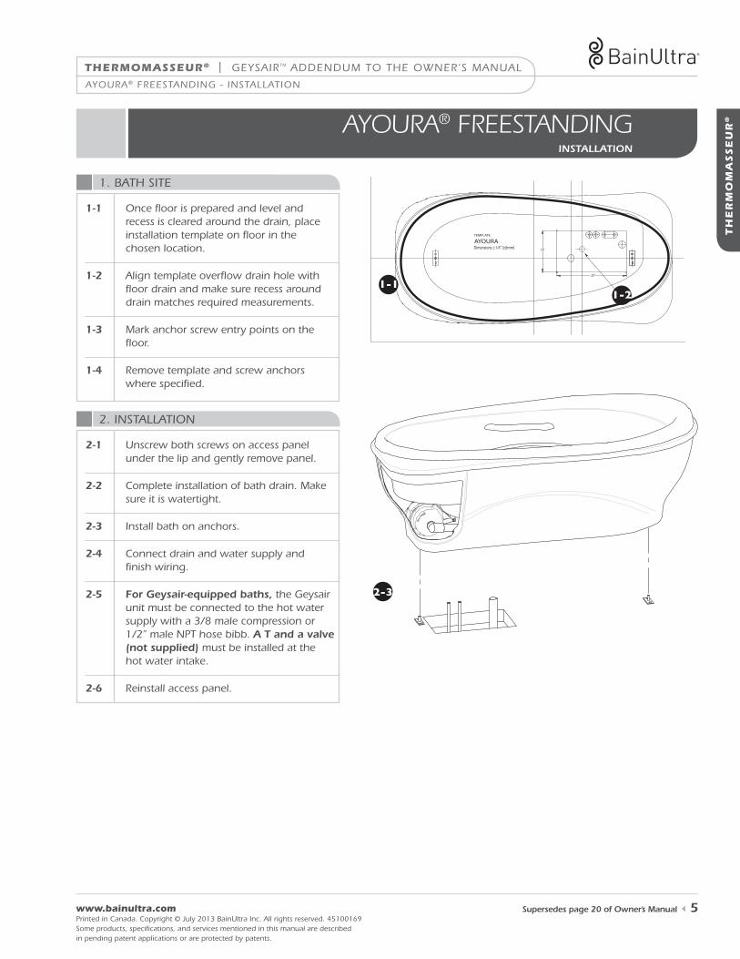
1-1 once floor is prepared and level and recess is cleared around the drain, place installation template on floor in the chosen location.
1-2 align template overflow drain hole with floor drain and make sure recess around drain matches required measurements.
1-3 mark anchor screw entry points on the floor.
1-4 remove template and screw anchors where specified.
TEMPLATE:
AYOURADimensions: ±1/4" [±6mm]
12"
20"
1-11-2
2-3
ayoura® freestanding - installation
2-1 unscrew both screws on access panel under the lip and gently remove panel.
2-2 Complete installation of bath drain. make sure it is watertight.
2-3 install bath on anchors.
2-4 Connect drain and water supply and finish wiring.
2-5 for geysair-equipped baths, the geysair unit must be connected to the hot water supply with a 3/8 male compression or 1/2” male nPt hose bibb. a t and a valve (not supplied) must be installed at the hot water intake.
2-6 reinstall access panel.
geysairtm addendum to the owner’s manual | tHERMOMASSEUR®
1 800 463.2187 From 8 a.m. to 8 p.m. Monday to Thursday (EST) From 8 a.m. to 5 p.m. on Friday (EST) Printed in Canada. Copyright © July 2013 Bainultra inc. all rights reserved. 45100169
some products, specifications, and services mentioned in this manual are described in pending patent applications or are protected by patents.
6 supersedes page 21 of owner’s Manual
amma® freestanding - installation
amma® fReestandInGinstallation
1. Bath site
2. installation
2-5
1-1
1-2
2-6
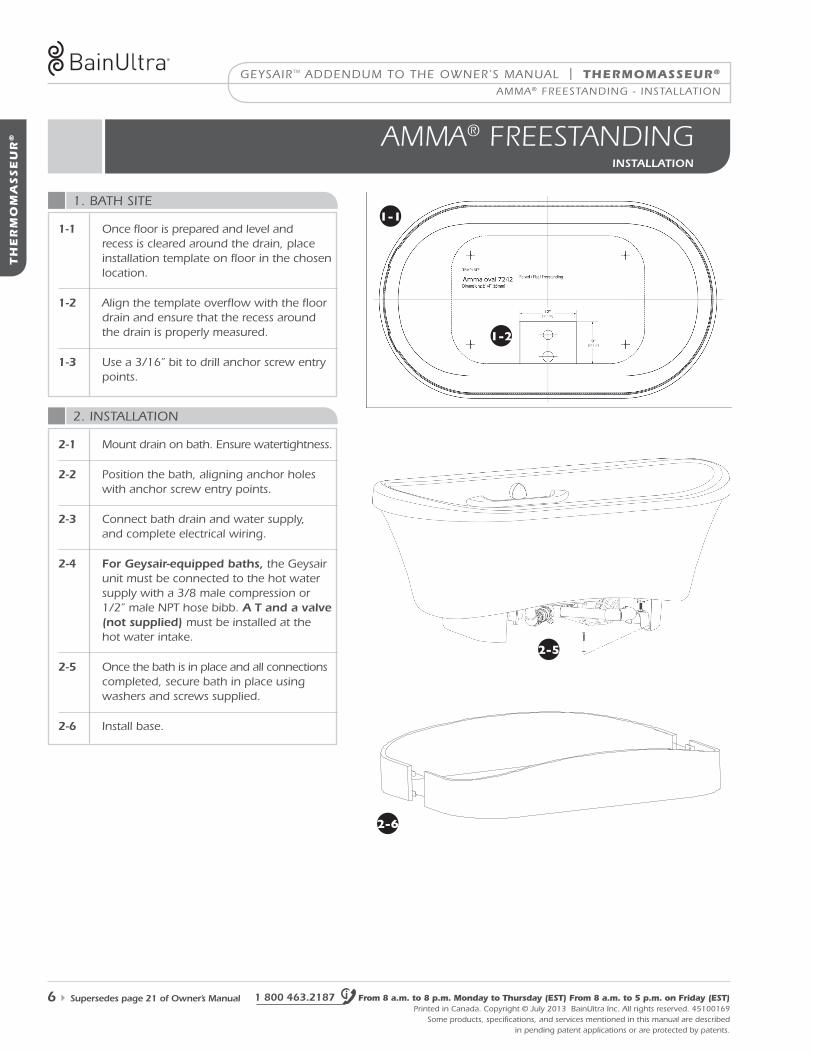
1-1 once floor is prepared and level and recess is cleared around the drain, place installation template on floor in the chosen location.
1-2 align the template overflow with the floor drain and ensure that the recess around the drain is properly measured.
1-3 use a 3/16” bit to drill anchor screw entry points.
2-1 mount drain on bath. ensure watertightness.
2-2 Position the bath, aligning anchor holes with anchor screw entry points.
2-3 Connect bath drain and water supply, and complete electrical wiring.
2-4 for geysair-equipped baths, the geysair unit must be connected to the hot water supply with a 3/8 male compression or 1/2” male nPt hose bibb. a t and a valve (not supplied) must be installed at the hot water intake.
2-5 once the bath is in place and all connections completed, secure bath in place using washers and screws supplied.
2-6 install base.
TH
ER
MO
MA
SSE
UR
®
tHERMOMASSEUR® | geysairtm addendum to the owner’s manual
tH
ER
MO
MA
SSE
UR
®
www.bainultra.com Printed in Canada. Copyright © July 2013 Bainultra inc. all rights reserved. 45100169some products, specifications, and services mentioned in this manual are described in pending patent applications or are protected by patents.
supersedes page 22 of owner’s Manual 7
2. installation
balneo® - naos & sanos installation
1. Bath site
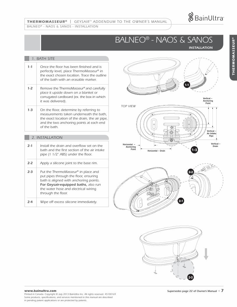
1-1 once the floor has been finished and is perfectly level, place thermomasseur® in the exact chosen location. trace the outline of the bath with an erasable marker.
1-2 remove the thermomasseur® and carefully place it upside down on a blanket or corrugated cardboard (ex. the box in which it was delivered).
1-3 on the floor, determine by referring to measurements taken underneath the bath, the exact location of the drain, the air pipe, and the two anchoring points at each end of the bath.
Balneo® - naos & sanos - installation
2-1
2-2
2-3
1-1
Horizontal – Drain
Horizontal – Anchoring
Point
Vertical – Drain
Vertical – Anchoring
Point
Vertical –Air Intake
Pipe
1- 3
toP view
2-1 install the drain and overflow set on the bath and the first section of the air intake pipe (1 1/2’’ aBs) under the floor.
2-2 apply a silicone joint to the base rim.
2-3 Put the thermomasseur® in place and put pipes through the floor, ensuring bath is aligned with anchoring points. for geysair-equipped baths, also run the water hose and electrical wiring through the floor.
2-4 wipe off excess silicone immediately.

geysairtm addendum to the owner’s manual | tHERMOMASSEUR®
1 800 463.2187 From 8 a.m. to 8 p.m. Monday to Thursday (EST) From 8 a.m. to 5 p.m. on Friday (EST) Printed in Canada. Copyright © July 2013 Bainultra inc. all rights reserved. 45100169
some products, specifications, and services mentioned in this manual are described in pending patent applications or are protected by patents.
TH
ER
MO
MA
SSE
UR
®
8 supersedes page 22 of owner’s Manual
2. installation (cont’d)
once plumbing is fully installed and before beginning any other work, fill the thermomasseur® to overflow and wait 30 minutes. Check all plumbing hook-ups and bath for leaks. Bainultra® is not responsible for any water damage caused by improper installation (see warranty section).
install turbine and inmix power module connections according to specifications outlined in the MiaMulti® electrical installation - turBine section.
leaK test
eleCtriCity
balneo® - naos & sanos installation
notes • since these models sit directly on the floor, the overflow drain pipe opening is factory-drilled.
• to installation of the naos or sanos on a concrete slab with no access below for air entry to the bath: a hole of 1 5/8 inch (4.1 cm) in diameter must be drilled into the bath skirt to allow air supply to the bath. important: do not drill above height of existing hole in the skirt intended to connect drain to overflow.
Balneo® - naos & sanos - installation
2-5 for geysair-equipped baths, connect the geysair electrical wire supplied (orange label) to the turbine wire (also marked with an orange label) in the junction box. test for grounding continuity between the bath grounding terminal and the bath power supply. failure to perform the grounding continuity test could result in serious personal injury.
2-6 for geysair-equipped baths, the geysair unit must be connected to the hot water supply with a 3/8 male compression or 1/2“ male nPt hose bibb. a t and a valve (not supplied) must be installed at the hot water intake.
tHERMOMASSEUR® | geysairtm addendum to the owner’s manual
www.bainultra.com Printed in Canada. Copyright © July 2013 Bainultra inc. all rights reserved. 45100169some products, specifications, and services mentioned in this manual are described in pending patent applications or are protected by patents.
tH
ER
MO
MA
SSE
UR
®
supersedes page 23 of owner’s Manual 9
balneo® - cellainstallation
1. Bath site
2. installation
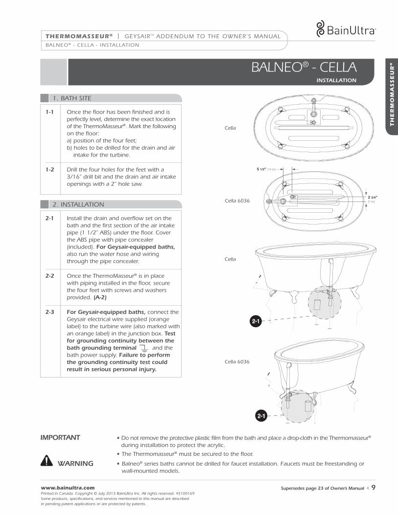
iMportant • do not remove the protective plastic film from the bath and place a drop-cloth in the thermomasseur® during installation to protect the acrylic.
• the thermomasseur® must be secured to the floor.
2 3/4" [7 cm]
5 1/2" [14 cm]
2-1
2-1
Cella
Cella 6036
Cella
Cella 6036
1-1 once the floor has been finished and is perfectly level, determine the exact location of the thermomasseur®. mark the following on the floor: a) position of the four feet; b) holes to be drilled for the drain and air intake for the turbine.
1-2 drill the four holes for the feet with a 3/16’’ drill bit and the drain and air intake openings with a 2’’ hole saw.
Balneo® - Cella - installation
• Balneo® series baths cannot be drilled for faucet installation. faucets must be freestanding or wall-mounted models.
warning
2-1 install the drain and overflow set on the bath and the first section of the air intake pipe (1 1/2’’ aBs) under the floor. Cover the aBs pipe with pipe concealer (included). for geysair-equipped baths,
also run the water hose and wiring through the pipe concealer.
2-2 once the thermomasseur® is in place with piping installed in the floor, secure the four feet with screws and washers provided. (a-2)
2-3 for geysair-equipped baths, connect the geysair electrical wire supplied (orange label) to the turbine wire (also marked with an orange label) in the junction box. test for grounding continuity between the bath grounding terminal and the bath power supply. failure to perform the grounding continuity test could result in serious personal injury.
geysairtm addendum to the owner’s manual | THERMOMASSEUR®
1 800 463.2187 From 8 a.m. to 8 p.m. Monday to Thursday (EST) From 8 a.m. to 5 p.m. on Friday (EST) Printed in Canada. Copyright © July 2013 Bainultra inc. all rights reserved. 45100169
some products, specifi cations, and services mentioned in this manual are describedin pending patent applications or are protected by patents.
TH
ER
MO
MA
SSE
UR
®
10 supersedes page 25 of owner’s Manual
origami freestanding design series - installation
2. installation
1. loCation
oRIGamI fReestandInG desIGn seRIesinstallation
1-1 2-1 2-3 2-62-2
1-1 2-1 2-3 2-62-2
1-1 2-1 2-3 2-62-2
1-1 2-1 2-3 2-62-2
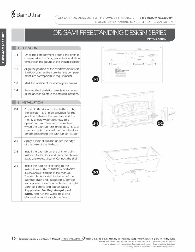
2-1 assemble the drain on the bathtub. usethe fl exible 1 1/2” pipe provided for thejunction between the overfl ow and thet-joint. ensure watertightness. thisoperation is much easier to complete when the bathtub rests on its side. Place a cover or protective cardboard on the fl oor before positioning the bathtub on its side.
2-2 apply a joint of silicone under the edgeof the base of the bathtub.
2-3 install the bathtub on the anchor points fastened to the fl oor and immediately wipe away any excess silicone. Connect the drain.
2-4 install the turbine according to theinstructions in the turBine – distanCeinstallation section of the manual.the air inlet is located to the left of thebathtub drain and, ifapplicable, controland option connection cables to the right. Connect control and option cablesif applicable. for geysair-equipped baths, also run the water hose and electrical wiring through the fl oor.
1-1 once the compartment around the drain is completed in the fl oor, place the installation template on the ground at the chosen location.
1-2 align the position of the overfl ow drain with the fl oor drain and ensure that the compart-ment size corresponds to requirements.
1-3 mark the location of the anchor point screws.
1-4 remove the installation template and screw in the anchor points in the marked locations.
THERMOMASSEUR® | geysairtm addendum to the owner’s manual
www.bainultra.com Printed in Canada. Copyright © July 2013 Bainultra inc. all rights reserved. 45100169some products, specifi cations, and services mentioned in this manual are described in pending patent applications or are protected by patents.
TH
ER
MO
MA
SSE
UR
®
supersedes page 25 of owner’s Manual 11
origami freestanding design series - installation
2. installation (cont’d)
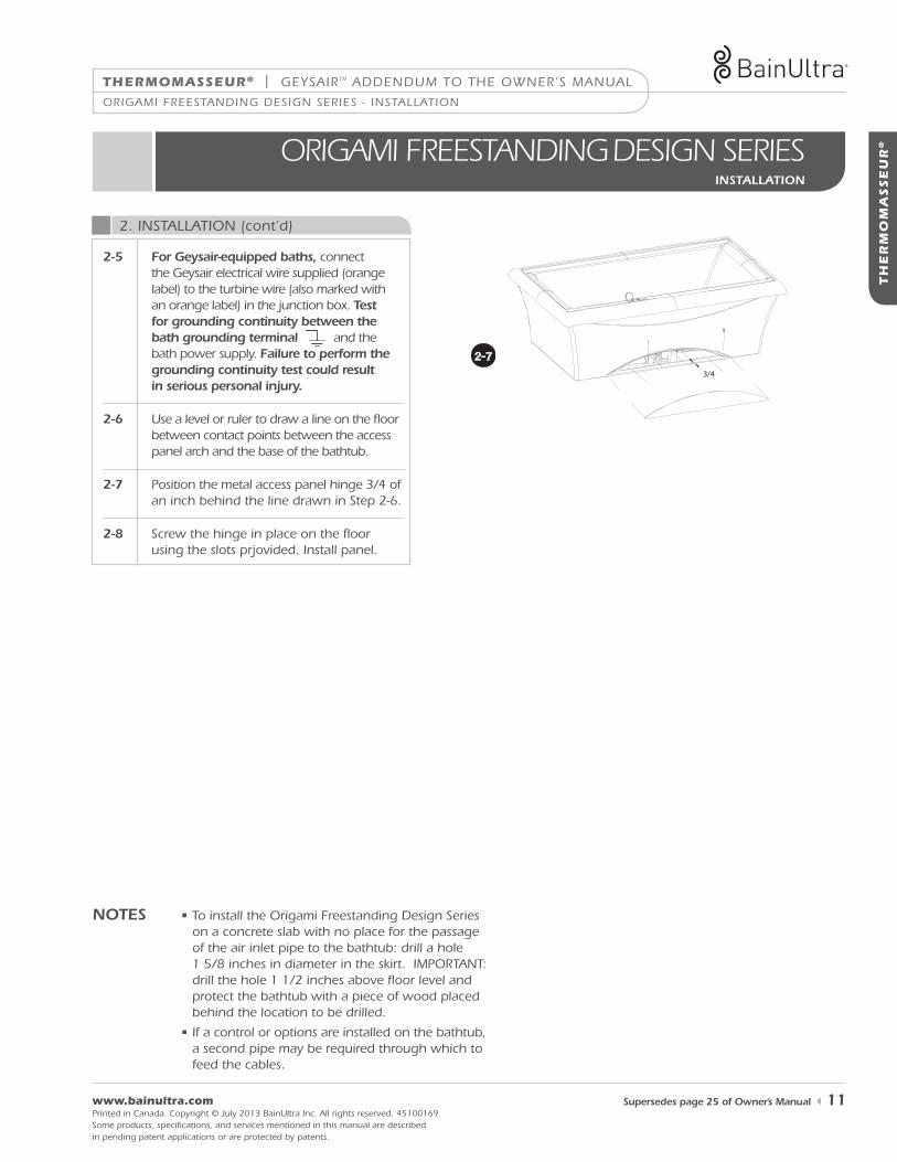
notes • to install the origami freestanding design series on a concrete slab with no place for the passage of the air inlet pipe to the bathtub: drill a hole 1 5/8 inches in diameter in the skirt. imPortant: drill the hole 1 1/2 inches above fl oor level and protect the bathtub with a piece of wood placed behind the location to be drilled.
• if a control or options are installed on the bathtub, a second pipe may be required through which to feed the cables.
oRIGamI fReestandInG desIGn seRIesinstallation
3/4
1-1 2-1 2-3 2-6 2-72-2
2-5 for geysair-equipped baths, connect the geysair electrical wire supplied (orange label) to the turbine wire (also marked with an orange label) in the junction box. test for grounding continuity between the bath grounding terminal and the bath power supply. failure to perform the grounding continuity test could result in serious personal injury.
2-6 use a level or ruler to draw a line on the fl oor between contact points between the access panel arch and the base of the bathtub.
2-7 Position the metal access panel hinge 3/4 ofan inch behind the line drawn in step 2-6.
2-8 screw the hinge in place on the fl oor using the slots prjovided. install panel.
1 800 463.2187 From 8 a.m. to 8 p.m. Monday to Thursday (EST) From 8 a.m. to 5 p.m. on Friday (EST) Printed in Canada. Copyright © July 2013 Bainultra inc. all rights reserved. 45100169
some products, specifications, and services mentioned in this manual are described in pending patent applications or are protected by patents.
TH
ER
MO
MA
SSE
UR
®
12
geysairtm addendum to the owner’s manual | THERMOMASSEUR®
TH
ER
MO
MA
SSE
UR
®
essenCia oval 7236 - Parts and tools - installation
essencIa oval 7236parts anD tools
essencIa oval 7236installation
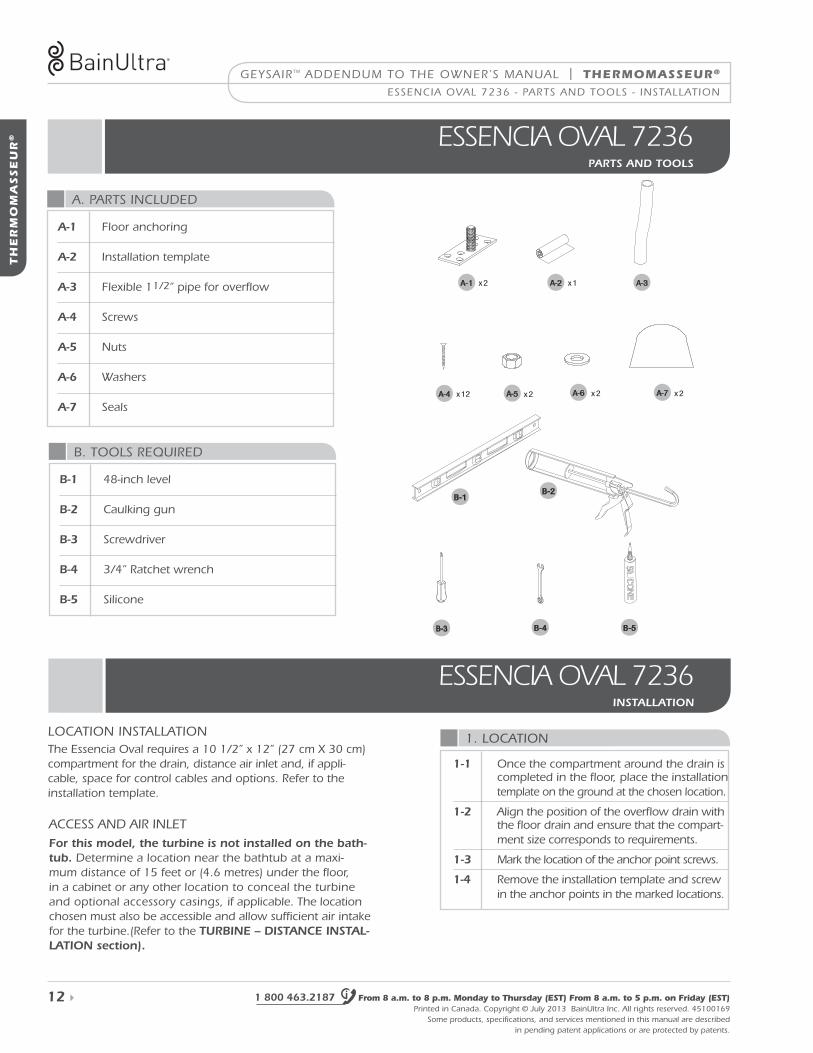
B. tools reQuired
loCation installationthe essencia oval requires a 10 1/2” x 12” (27 cm X 30 cm)compartment for the drain, distance air inlet and, if appli-cable, space for control cables and options. refer to the installation template.
aCCess and air inletfor this model, the turbine is not installed on the bath-tub. determine a location near the bathtub at a maxi-mum distance of 15 feet or (4.6 metres) under the floor, in a cabinet or any other location to conceal the turbine and optional accessory casings, if applicable. the location chosen must also be accessible and allow sufficient air intake for the turbine.(refer to the turBine – Distance instal-lation section).
B-1 48-inch level
B-2 Caulking gun
B-3 screwdriver
B-4 3/4” ratchet wrench
B-5 silicone
a. Parts inCluded
a-1 floor anchoring
a-2 installation template
a-3 flexible 11/2” pipe for overflow
a-4 screws
a-5 nuts
a-6 washers
a-7 seals
B-2B-1
B-4 B-5B-3
A-1 x2
x2 x2
x1
x12
A-3
A-4 A-5 A-6 x2A-7
A-2
1. loCation
1-1 once the compartment around the drain is completed in the floor, place the installation template on the ground at the chosen location.
1-2 align the position of the overflow drain with the floor drain and ensure that the compart-ment size corresponds to requirements.
1-3 mark the location of the anchor point screws.
1-4 remove the installation template and screw in the anchor points in the marked locations.
THERMOMASSEUR® | geysairtm addendum to the owner’s manual
www.bainultra.com Printed in Canada. Copyright © July 2013 Bainultra inc. all rights reserved. 45100169some products, specifi cations, and services mentioned in this manual are described in pending patent applications or are protected by patents.
TH
ER
MO
MA
SSE
UR
®
13
essenCia oval 7236 - installation
2. installation
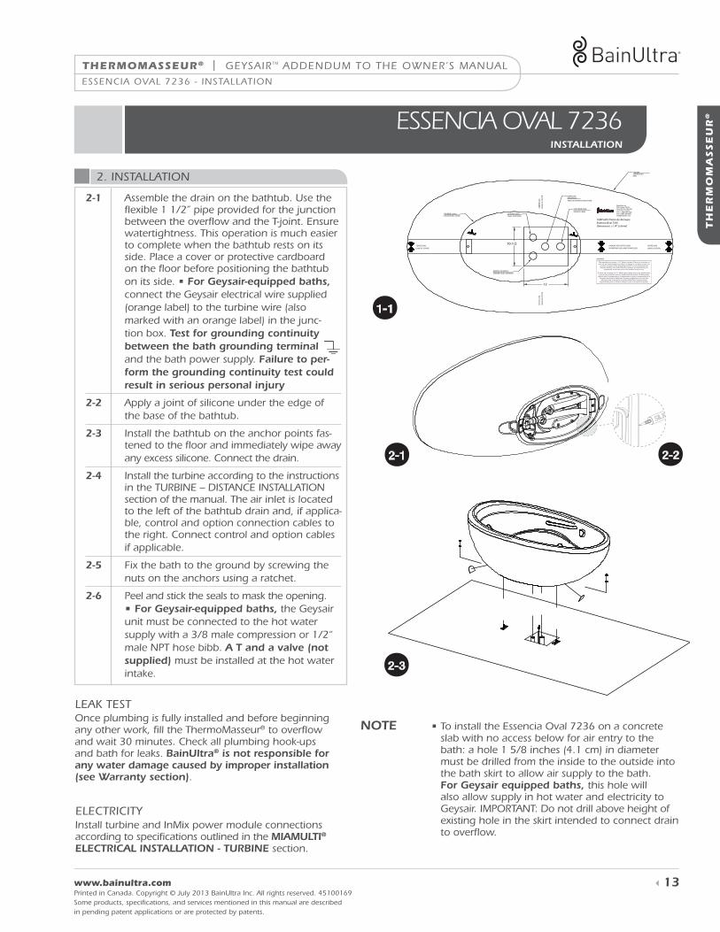
note • to install the essencia oval 7236 on a concrete slab with no access below for air entry to the bath: a hole 1 5/8 inches (4.1 cm) in diameter must be drilled from the inside to the outside into the bath skirt to allow air supply to the bath. for geysair equipped baths, this hole will also allow supply in hot water and electricity to geysair. imPortant: do not drill above height of existing hole in the skirt intended to connect drain to overfl ow.
essencIa oval 7236installation
10-1/2
12
90000056
CENTER LINE OVERLAP THE DOTTED LINESSUPERPOSER LES LIGNES POINTILLÉES
TUB BASE outlineCONTOUR DE LA BASE
CEN
TER
LIN
E
LIG
NE
DE
CEN
TRE
CEN
TER
LIN
E
LIG
NE
DE
CEN
TRE
LIGNE DE CENTRECENTER LINELIGNE DE CENTRE
TUB RIMCONTOUR DU BAIN
TUB DRAIN HOLE
DRAIN DU BAIN
OVERFLOWDRAIN HOLETROU DU DRAIN DU TROP PLEIN
OPTIONS CABLECABLE D'OPTIONS
REMOTE AIR SUPPLY ARRIVÉE D'AIR À DISTANCE
TEMPLATE Patron de découpeEssencia Oval 7236Dimensions + _ 1/4” [+ _ 6mm]
1-1 2-1 2-3 2-62-2
1-1 2-1 2-3 2-62-2
1-1 2-1 2-3 2-62-2
1-1 2-1 2-3 2-62-2
2-1 assemble the drain on the bathtub. use the fl exible 1 1/2” pipe provided for the junction between the overfl ow and the t-joint. ensure watertightness. this operation is much easier to complete when the bathtub rests on its side. Place a cover or protective cardboard on the fl oor before positioning the bathtub on its side. • for geysair-equipped baths, connect the geysair electrical wire supplied (orange label) to the turbine wire (also marked with an orange label) in the junc-tion box. test for grounding continuity between the bath grounding terminal and the bath power supply. failure to per-form the grounding continuity test could result in serious personal injury
2-2 apply a joint of silicone under the edge of the base of the bathtub.
2-3 install the bathtub on the anchor points fas-tened to the fl oor and immediately wipe away any excess silicone. Connect the drain.
2-4 install the turbine according to the instructions in the turBine – distanCe installation section of the manual. the air inlet is located to the left of the bathtub drain and, if applica-ble, control and option connection cables to the right. Connect control and option cablesif applicable.
2-5 fix the bath to the ground by screwing the nuts on the anchors using a ratchet.
2-6 Peel and stick the seals to mask the opening. • for geysair-equipped baths, the geysair unit must be connected to the hot water supply with a 3/8 male compression or 1/2“ male nPt hose bibb. a t and a valve (not supplied) must be installed at the hot water intake.
once plumbing is fully installed and before beginning any other work, fi ll the thermomasseur® to overfl ow and wait 30 minutes. Check all plumbing hook-ups and bath for leaks. Bainultra® is not responsible for any water damage caused by improper installation (see warranty section).
leaK test
install turbine and inmix power module connections according to specifi cations outlined in the MiaMulti® electrical installation - turBine section.
eleCtriCity
geysairtm addendum to the owner’s manual | tHERMOMASSEUR®
1 800 463.2187 From 8 a.m. to 8 p.m. Monday to Thursday (EST) From 8 a.m. to 5 p.m. on Friday (EST) Printed in Canada. Copyright © July 2013 Bainultra inc. all rights reserved. 45100169
some products, specifications, and services mentioned in this manual are described in pending patent applications or are protected by patents.
TH
ER
MO
MA
SSE
UR
®
14
TH
ER
MO
MA
SSE
UR
® essencIa RectanGUlaR 6838 fReestandInGparts anD tools
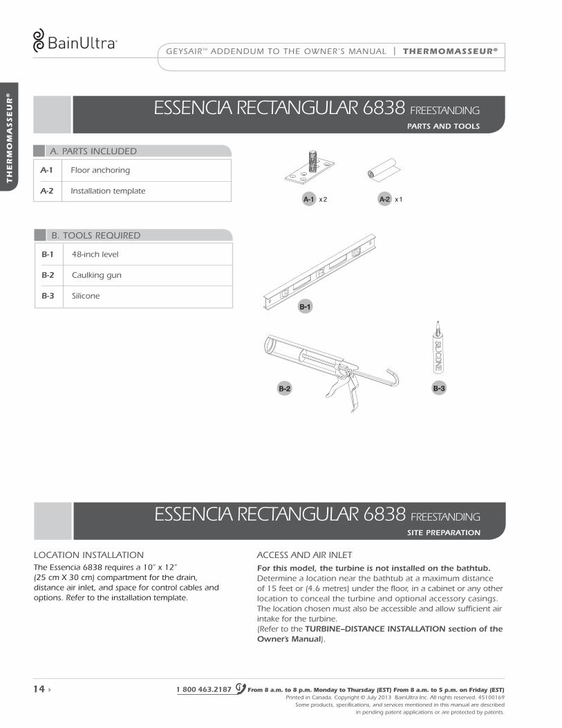
B. tools reQuired
B-1 48-inch level
B-2 Caulking gun
B-3 silicone
a. Parts inCluded
a-1 floor anchoring
a-2 installation template
B-2
B-1
B-3
A-1 x2 x1A-2
essencIa RectanGUlaR 6838 fReestandInGsite preparation
loCation installationthe essencia 6838 requires a 10” x 12” (25 cm X 30 cm) compartment for the drain, distance air inlet, and space for control cables and options. refer to the installation template.
aCCess and air inletfor this model, the turbine is not installed on the bathtub. determine a location near the bathtub at a maximum distance of 15 feet or (4.6 metres) under the floor, in a cabinet or any other location to conceal the turbine and optional accessory casings. the location chosen must also be accessible and allow sufficient air intake for the turbine. (refer to the turBine–Distance installation section of the owner’s Manual).
THERMOMASSEUR® | geysairtm addendum to the owner’s manual
www.bainultra.com Printed in Canada. Copyright © July 2013 Bainultra inc. all rights reserved. 45100169some products, specifi cations, and services mentioned in this manual are described in pending patent applications or are protected by patents.
TH
ER
MO
MA
SSE
UR
®
15
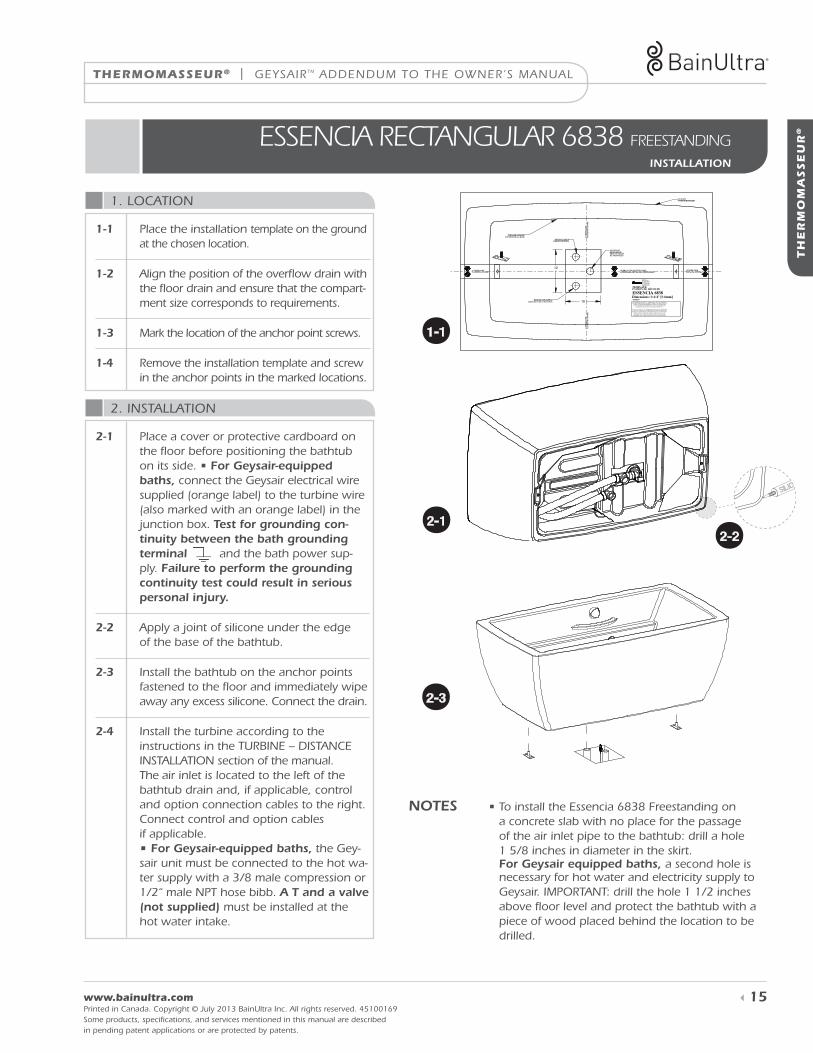
2. installation
1. loCation
notes • to install the essencia 6838 freestanding on a concrete slab with no place for the passage of the air inlet pipe to the bathtub: drill a hole 1 5/8 inches in diameter in the skirt. for geysair equipped baths, a second hole is necessary for hot water and electricity supply to geysair. imPortant: drill the hole 1 1/2 inches above fl oor level and protect the bathtub with a piece of wood placed behind the location to be drilled.
essencIa RectanGUlaR 6838 fReestandInGinstallation
12
10
BainUltra inc.956 chemin OlivierSaint-Nicolas (Quebec)G7A 2N1, CanadaTel.: 1 (800) 463-2187Fax: 1(800) [email protected]
TEMPLATE:PATRON DE DÉCOUPE
ESSENCIA 6838Dimensions: 1/4" [ 6mm]90000057
CENTER LINELIGNE DE CENTRE
CENTER LINELIGNE DE CENTRE
OVERLAP THE DOTTED LINESSUPERPOSER LES LIGNES POINTILLÉES
TUB BASE OUTLINECONTOUR DE LA BASE
CE
NT
ER
LIN
EL
IGN
E D
E C
EN
TR
EC
EN
TE
R L
INE
LIG
NE
DE
CE
NT
RE
TUB RIMCONTOUR DU BAIN
OVERFLOWDRAIN HOLETROU DU DRAINDU TROP-PLEIN
OPTIONS CABLECABLE D'OPTIONS
REMOTE AIR SUPPLYARRIVÉE D'AIR À DISTANCE The manufacturer accepts a 1/4" [6mm] variance.There are variations on
each tub and specifications are subject to change as we improve upon ourproducts as required.The dimensions needed for site preparation andstructure building will differ.BainUltra assumes no responsibility for
preparatory work done prior to the product being on site.
Il existe une variation de 1/4" [6mm] pour chaque bain et les spécificationspeuvent être modifiées suite à l'amélioration du produit.Les dimensions
requises pour la préparation de l'emplacement et pour la construction de lastructure peuvent être différentes.Aucune construction ne devrait êtreeffectuée avant la réception du produit.BainUltra n'assume aucune
responsabilité pour les travaux entrepris avant la réception du produit.
1-1 2-1 2-3 2-62-2
1-1 2-1 2-3 2-62-2
1-1 2-1 2-3 2-62-2
1-1 2-1 2-3 2-62-2
2-1 Place a cover or protective cardboard on the fl oor before positioning the bathtub on its side. • for geysair-equipped baths, connect the geysair electrical wire supplied (orange label) to the turbine wire (also marked with an orange label) in the junction box. test for grounding con-tinuity between the bath grounding terminal and the bath power sup-ply. failure to perform the grounding continuity test could result in serious personal injury.
2-2 apply a joint of silicone under the edgeof the base of the bathtub.
2-3 install the bathtub on the anchor points fastened to the fl oor and immediately wipe away any excess silicone. Connect the drain.
2-4 install the turbine according to theinstructions in the turBine – distanCeinstallation section of the manual.the air inlet is located to the left of thebathtub drain and, if applicable, controland option connection cables to the right. Connect control and option cablesif applicable.• for geysair-equipped baths, the gey-sair unit must be connected to the hot wa-ter supply with a 3/8 male compression or 1/2“ male nPt hose bibb. a t and a valve (not supplied) must be installed at the hot water intake.
1-1 Place the installation template on the ground at the chosen location.
1-2 align the position of the overfl ow drain with the fl oor drain and ensure that the compart-ment size corresponds to requirements.
1-3 mark the location of the anchor point screws.
1-4 remove the installation template and screw in the anchor points in the marked locations.
TU
RB
INE
geysairtm addendum to the owner’s manual | TURBINE
1 800 463.2187 From 8 a.m. to 8 p.m. Monday to Thursday (EST) From 8 a.m. to 5 p.m. on Friday (EST) Printed in Canada. Copyright © July 2013 Bainultra inc. all rights reserved. 45100169
some products, specifications, and services mentioned in this manual are described in pending patent applications or are protected by patents.
16 supersedes page 26 of owner’s Manual
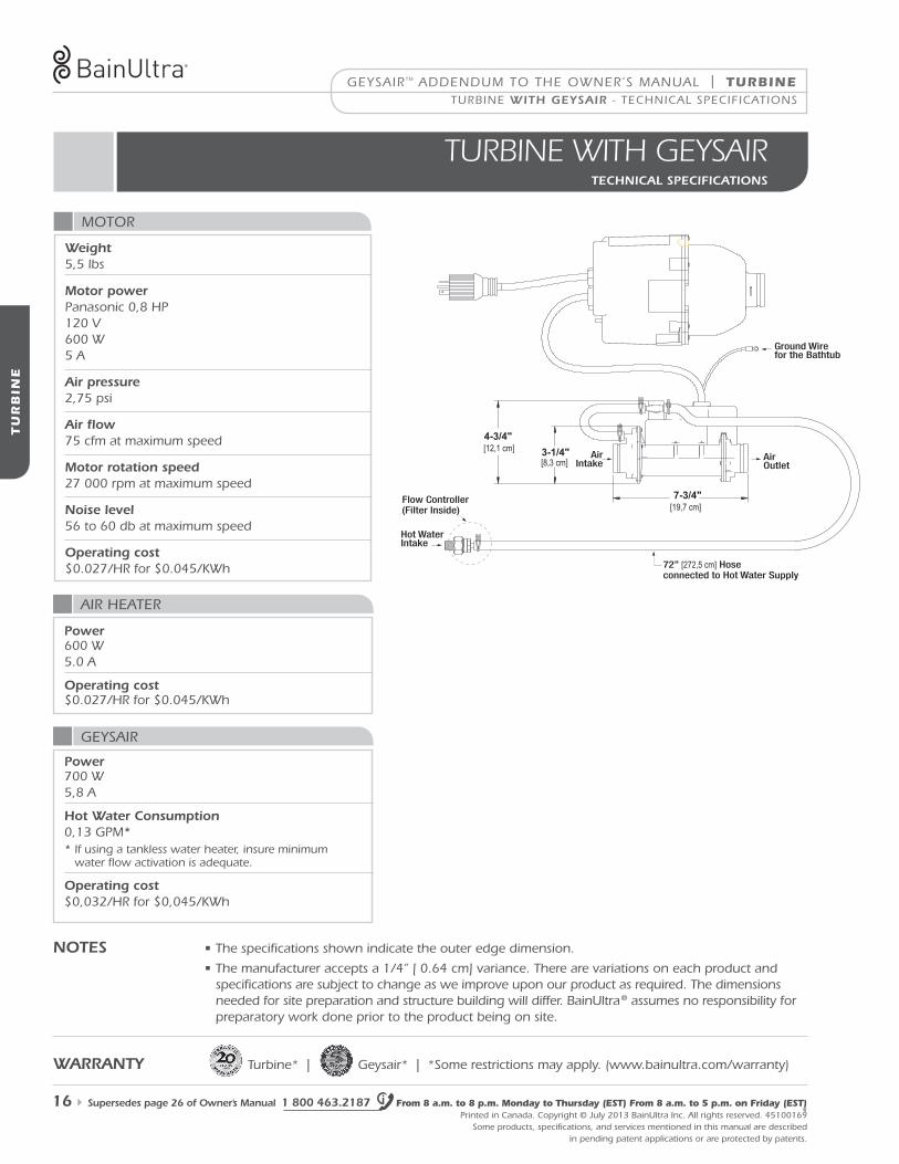
tURbIne wIth GeYsaIRtecHnical specifications
notes • the specifications shown indicate the outer edge dimension.
• the manufacturer accepts a 1/4” [ 0.64 cm] variance. there are variations on each product and specifications are subject to change as we improve upon our product as required. the dimensions needed for site preparation and structure building will differ. Bainultra ® assumes no responsibility for preparatory work done prior to the product being on site.
warranty turbine* | geysair* | *some restrictions may apply. (www.bainultra.com/warranty)
AirIntake
Air Outlet
Ground Wire for the Bathtub
Hot WaterIntake
4-3/4"[12,1 cm]
[8,3 cm]
[19,7 cm]7-3/4"
3-1/4"
Flow Controller(Filter Inside)
72” [272,5 cm] Hose connected to Hot Water Supply
motor
air heater
power 600 w 5.0 a
operating cost $0.027/hr for $0.045/Kwh
weight 5,5 lbs
Motor power Panasonic 0,8 hP 120 v 600 w 5 a
air pressure 2,75 psi
air flow 75 cfm at maximum speed
Motor rotation speed 27 000 rpm at maximum speed
noise level 56 to 60 db at maximum speed
operating cost $0.027/hr for $0.045/Kwh
turBine witH geysair - teChniCal sPeCifiCations
geysair
power 700 w 5,8 a
Hot water consumption 0,13 gPm* * if using a tankless water heater, insure minimum
water flow activation is adequate.
operating cost $0,032/hr for $0,045/Kwh
TU
RB
INE
TURBINE | geysairtm addendum to the owner’s manual
www.bainultra.com Printed in Canada. Copyright © July 2013 Bainultra inc. all rights reserved. 45100169some products, specifications, and services mentioned in this manual are described in pending patent applications or are protected by patents.
supersedes page 27 of owner’s Manual 17
turBine witH geysair - eleCtriCal installation & PlumBing
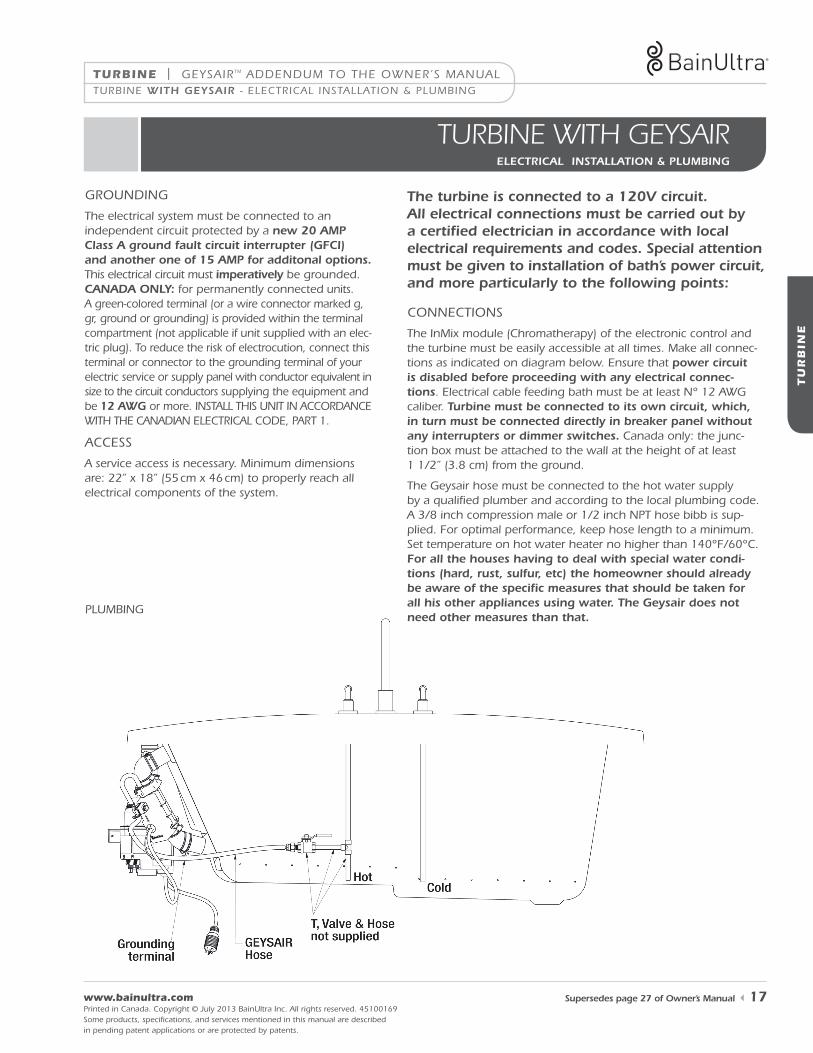
tURbIne wIth GeYsaIR electrical installation & pluMBing
the turbine is connected to a 120V circuit. all electrical connections must be carried out by a certified electrician in accordance with local electrical requirements and codes. special attention must be given to installation of bath’s power circuit, and more particularly to the following points:
the electrical system must be connected to an independent circuit protected by a new 20 aMp class a ground fault circuit interrupter (gfci) and another one of 15 aMp for additonal options. this electrical circuit must imperatively be grounded. canaDa only: for permanently connected units. a green-colored terminal (or a wire connector marked g, gr, ground or grounding) is provided within the terminal compartment (not applicable if unit supplied with an elec-tric plug). to reduce the risk of electrocution, connect this terminal or connector to the grounding terminal of your electric service or supply panel with conductor equivalent in size to the circuit conductors supplying the equipment and be 12 awg or more. install this unit in aCCordanCe with the Canadian eleCtriCal Code, Part 1.
a service access is necessary. minimum dimensions are: 22” x 18” (55 cm x 46 cm) to properly reach all electrical components of the system.
grounding
aCCess
ConneCtions
PlumBing
the inmix module (Chromatherapy) of the electronic control and the turbine must be easily accessible at all times. make all connec-tions as indicated on diagram below. ensure that power circuit is disabled before proceeding with any electrical connec-tions. electrical cable feeding bath must be at least n° 12 awg caliber. turbine must be connected to its own circuit, which, in turn must be connected directly in breaker panel without any interrupters or dimmer switches. Canada only: the junc-tion box must be attached to the wall at the height of at least 1 1/2” (3.8 cm) from the ground.
the geysair hose must be connected to the hot water supply by a qualified plumber and according to the local plumbing code. a 3/8 inch compression male or 1/2 inch nPt hose bibb is sup-plied. for optimal performance, keep hose length to a minimum. set temperature on hot water heater no higher than 140°f/60°C. for all the houses having to deal with special water condi-tions (hard, rust, sulfur, etc) the homeowner should already be aware of the specific measures that should be taken for all his other appliances using water. the geysair does not need other measures than that.
TU
RB
INE
geysairtm addendum to the owner’s manual | TURBINE
1 800 463.2187 From 8 a.m. to 8 p.m. Monday to Thursday (EST) From 8 a.m. to 5 p.m. on Friday (EST) Printed in Canada. Copyright © July 2013 Bainultra inc. all rights reserved. 45100169
some products, specifications, and services mentioned in this manual are described in pending patent applications or are protected by patents.
18 supersedes page 28 of owner’s Manual
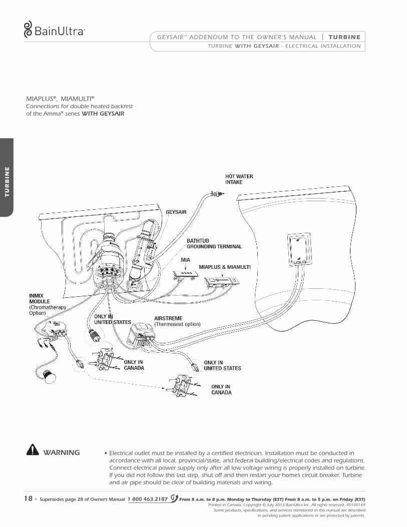
miaPlus®, miamulti®
Connections for double heated backrest of the amma® series witH geysair
• electrical outlet must be installed by a certified electrician. installation must be conducted in accordance with all local, provincial/state, and federal building/electrical codes and regulations. Connect electrical power supply only after all low voltage wiring is properly installed on turbine. if you did not follow this last step, shut off and then restart your home’s circuit breaker. turbine and air pipe should be clear of building materials and wiring.
warning
turBine witH geysair - eleCtriCal installation
TU
RB
INE
TURBINE | geysairtm addendum to the owner’s manual
www.bainultra.com Printed in Canada. Copyright © July 2013 Bainultra inc. all rights reserved. 45100169some products, specifications, and services mentioned in this manual are described in pending patent applications or are protected by patents.
supersedes page 29 of owner’s Manual 19
turBine witH geysair - eleCtriCal installation
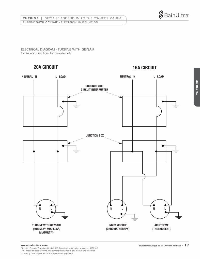
eleCtriCal diagram - turBine with geysairelectrical connections for Canada only
15A CIRCUIT 20A CIRCUIT
AIRSTREME(THERMOSEAT)
N L N LN L
NEUTRAL N L LOAD NEUTRAL N L LOAD
GROUND FAULTCIRCUIT INTERRUPTER
JUNCTION BOX
TURBINE WITH GEYSAIR(FOR MIA®, MIAPLUS®,
MIAMULTI®)
INMIX MODULE(CHROMATHERAPY)
TU
RB
INE
geysairtm addendum to the owner’s manual | TURBINE
1 800 463.2187 From 8 a.m. to 8 p.m. Monday to Thursday (EST) From 8 a.m. to 5 p.m. on Friday (EST) Printed in Canada. Copyright © July 2013 Bainultra inc. all rights reserved. 45100169
some products, specifications, and services mentioned in this manual are described in pending patent applications or are protected by patents.
20 supersedes page 31 of owner’s Manual
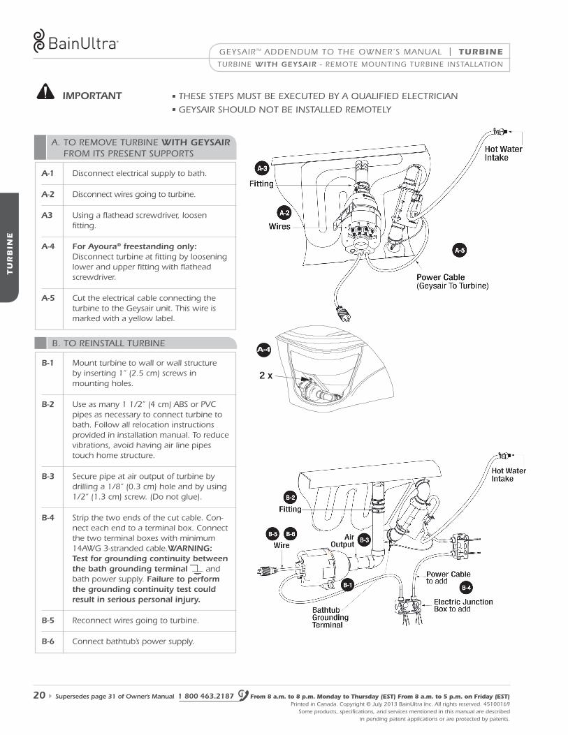
a. to remove turBine witH geysair from its Present suPPorts
B. to reinstall turBine
turBine witH geysair - remote mounting turBine installation
2 x
A-4
a-1 disconnect electrical supply to bath.
a-2 disconnect wires going to turbine.
a3 using a flathead screwdriver, loosen fitting.
a-4 for ayoura® freestanding only: disconnect turbine at fitting by loosening lower and upper fitting with flathead screwdriver.
a-5 Cut the electrical cable connecting the turbine to the geysair unit. this wire is marked with a yellow label.
B-1 mount turbine to wall or wall structure by inserting 1” (2.5 cm) screws in mounting holes.
B-2 use as many 1 1/2” (4 cm) aBs or PvC pipes as necessary to connect turbine to bath. follow all relocation instructions provided in installation manual. to reduce vibrations, avoid having air line pipes touch home structure.
B-3 secure pipe at air output of turbine by drilling a 1/8” (0.3 cm) hole and by using 1/2” (1.3 cm) screw. (do not glue).
B-4 strip the two ends of the cut cable. Con-nect each end to a terminal box. Connect the two terminal boxes with minimum 14awg 3-stranded cable.warning: test for grounding continuity between the bath grounding terminal and bath power supply. failure to perform the grounding continuity test could result in serious personal injury.
B-5 reconnect wires going to turbine.
B-6 Connect bathtub’s power supply.
iMportant • these stePs must Be eXeCuted By a Qualified eleCtriCian
• geysair should not Be installed remotely
TH
E M
IA® S
ER
IES C
ON
TR
OL
S
THE MIA® SERIES CONTROLS | geysairtm addendum to the owner’s manual
www.bainultra.com Printed in Canada. Copyright © July 2013 Bainultra inc. all rights reserved. 45100169some products, specifications, and services mentioned in this manual are described in pending patent applications or are protected by patents.
supersedes page 56 of owner’s Manual 21
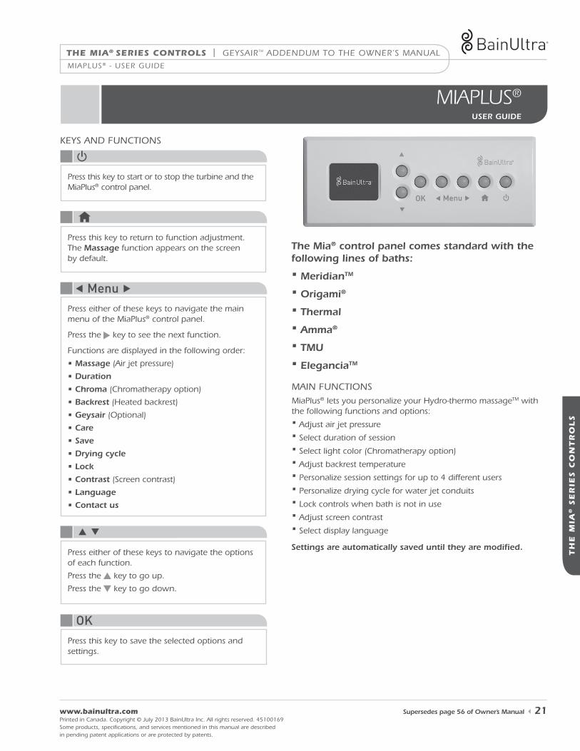
mIaPlUs®
user guiDe
the Mia® control panel comes standard with the following lines of baths:
• MeridiantM
• origami®
• thermal
• amma®
• tMu
• eleganciatM
settings are automatically saved until they are modified.
miaPlus® lets you personalize your hydro-thermo massagetm with the following functions and options:• adjust air jet pressure• select duration of session• select light color (Chromatherapy option)• adjust backrest temperature• Personalize session settings for up to 4 different users• Personalize drying cycle for water jet conduits• lock controls when bath is not in use• adjust screen contrast• select display language
main funCtions
Keys and funCtions
Press this key to start or to stop the turbine and the miaPlus® control panel.
Press this key to return to function adjustment. the Massage function appears on the screen by default.
Press either of these keys to navigate the main menu of the miaPlus® control panel.
Press the key to see the next function.
functions are displayed in the following order:
• Massage (air jet pressure)
• Duration
• chroma (Chromatherapy option)
• Backrest (heated backrest)
• geysair (optional)
• care
• save
• Drying cycle
• lock
• contrast (screen contrast)
• language
• contact us
Press either of these keys to navigate the options of each function.
Press the key to go up.
Press the key to go down.
Press this key to save the selected options and settings.
miaPlus® - user guide
geysairtm addendum to the owner’s manual | THE MIA® SERIES CONTROLS
TH
E M
IA® S
ER
IES C
ON
TR
OL
S
1 800 463.2187 From 8 a.m. to 8 p.m. Monday to Thursday (EST) From 8 a.m. to 5 p.m. on Friday (EST) Printed in Canada. Copyright © July 2013 Bainultra inc. all rights reserved. 45100169
some products, specifications, and services mentioned in this manual are described in pending patent applications or are protected by patents.
22 supersedes page 59 of owner’s Manual
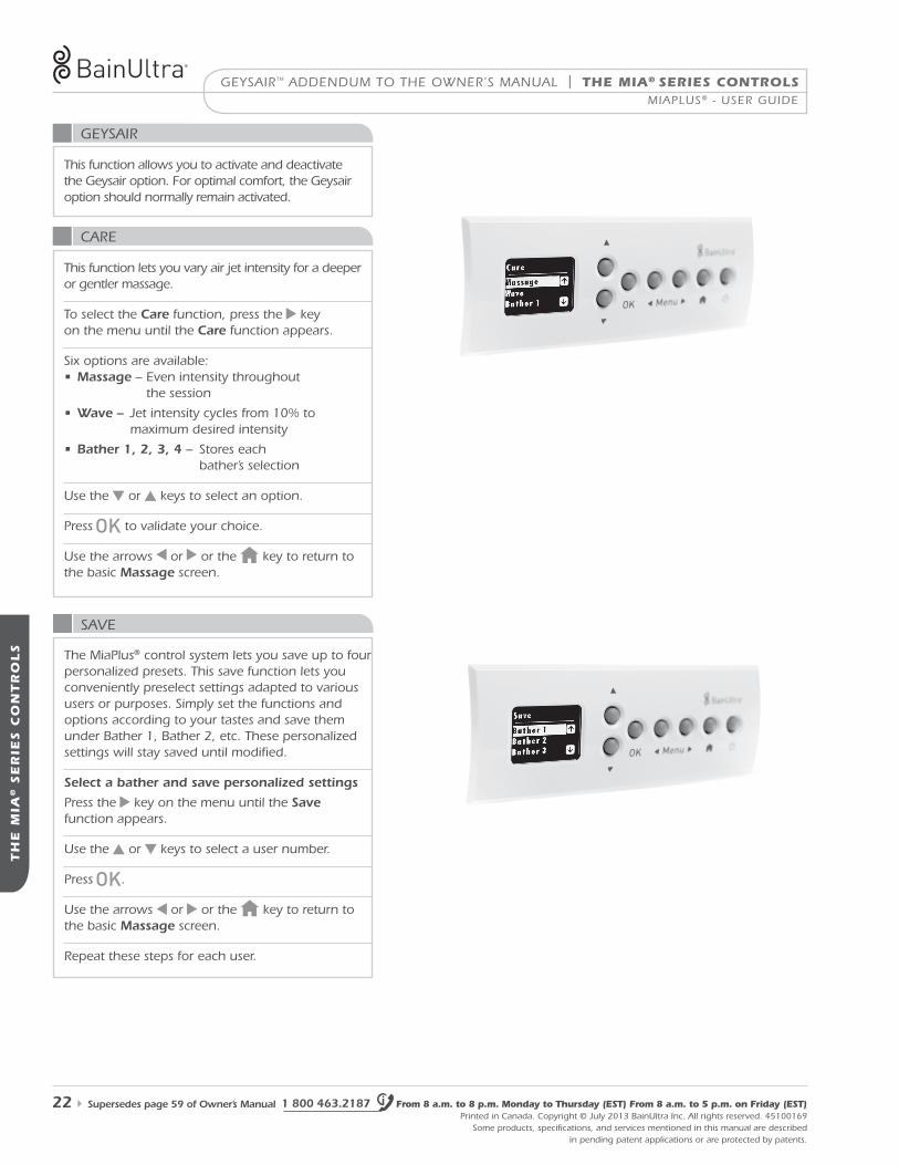
Care
save
this function lets you vary air jet intensity for a deeper or gentler massage.
to select the care function, press the key on the menu until the care function appears.
six options are available: • Massage – even intensity throughout the session
• wave – Jet intensity cycles from 10% to maximum desired intensity
• Bather 1, 2, 3, 4 – stores each bather’s selection
use the or keys to select an option.
Press to validate your choice.
use the arrows or or the key to return to the basic Massage screen.
the miaPlus® control system lets you save up to four personalized presets. this save function lets you conveniently preselect settings adapted to various users or purposes. simply set the functions and options according to your tastes and save them under Bather 1, Bather 2, etc. these personalized settings will stay saved until modified.
select a bather and save personalized settings
Press the key on the menu until the save function appears.
use the or keys to select a user number.
Press .
use the arrows or or the key to return to the basic Massage screen.
repeat these steps for each user.
miaPlus® - user guide
geysair
this function allows you to activate and deactivate the geysair option. for optimal comfort, the geysair option should normally remain activated.
TR
OU
BL
ESH
OO
TIN
G
TROUBLESHOOTING | geysairtm addendum to the owner’s manual
www.bainultra.com Printed in Canada. Copyright © July 2013 Bainultra inc. all rights reserved. 45100169some products, specifications, and services mentioned in this manual are described in pending patent applications or are protected by patents.
supersedes page 70 of owner’s Manual 23
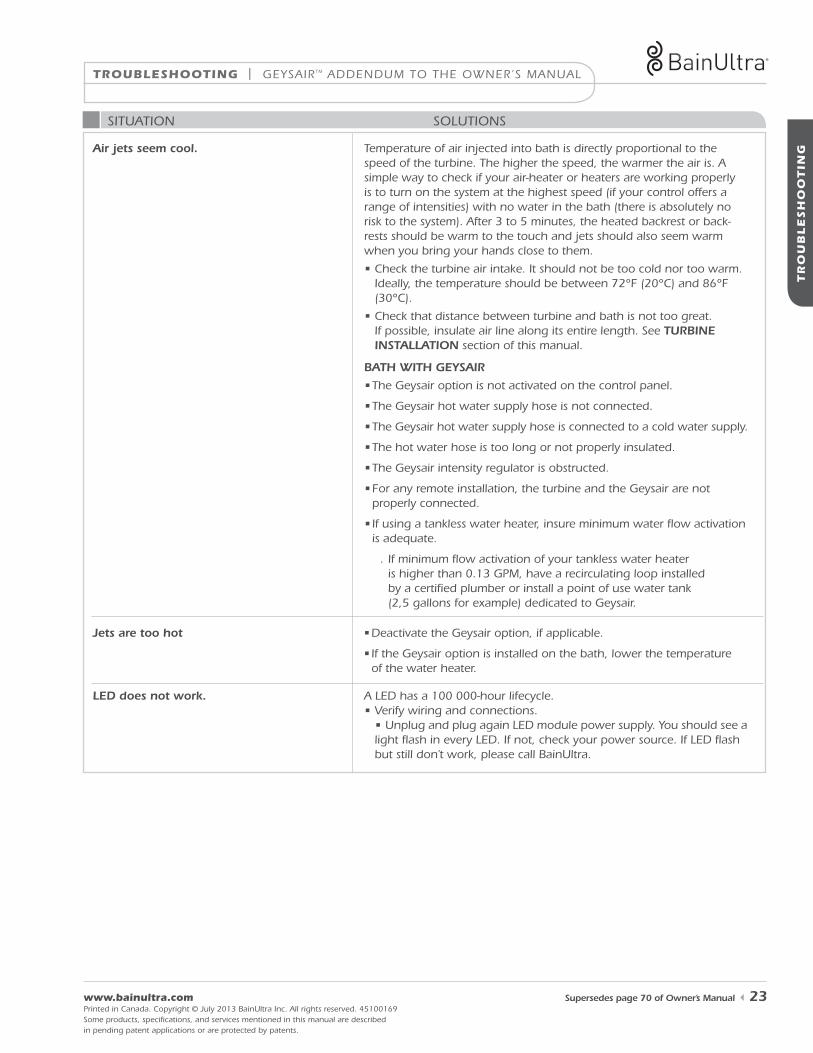
situation solutions
air jets seem cool.
a led has a 100 000-hour lifecycle. • verify wiring and connections.
• unplug and plug again led module power supply. you should see a light flash in every led. if not, check your power source. if led flash but still don’t work, please call Bainultra.
Jets are too hot • deactivate the geysair option, if applicable.
• if the geysair option is installed on the bath, lower the temperature of the water heater.
leD does not work.
temperature of air injected into bath is directly proportional to the speed of the turbine. the higher the speed, the warmer the air is. a simple way to check if your air-heater or heaters are working properly is to turn on the system at the highest speed (if your control offers a range of intensities) with no water in the bath (there is absolutely no risk to the system). after 3 to 5 minutes, the heated backrest or back-rests should be warm to the touch and jets should also seem warm when you bring your hands close to them.
• Check the turbine air intake. it should not be too cold nor too warm. ideally, the temperature should be between 72°f (20°C) and 86°f (30°C).
• Check that distance between turbine and bath is not too great. if possible, insulate air line along its entire length. see turBine installation section of this manual.
BatH witH geysair
• the geysair option is not activated on the control panel.
• the geysair hot water supply hose is not connected.
• the geysair hot water supply hose is connected to a cold water supply.
• the hot water hose is too long or not properly insulated.
• the geysair intensity regulator is obstructed.
• for any remote installation, the turbine and the geysair are not properly connected.
• if using a tankless water heater, insure minimum water flow activation is adequate.
. if minimum flow activation of your tankless water heater is higher than 0.13 gPm, have a recirculating loop installed by a certified plumber or install a point of use water tank (2,5 gallons for example) dedicated to geysair.

geysairtm addendum to the owner’s manual | Warranty
Wa
rr
an
ty
1 800 463.2187 From 8 a.m. to 8 p.m. Monday to Thursday (EST) From 8 a.m. to 5 p.m. on Friday (EST) Printed in Canada. Copyright © July 2013 Bainultra inc. all rights reserved. 45100169
some products, specifications, and services mentioned in this manual are described in pending patent applications or are protected by patents.
24 supersedes page 71 of owner’s Manual
the baInUltRa® lImIted waRRantY
liMiteD warranty
this limited warranty is extended only to the original purchaser of the unit under warranty and is valid only when bought through and registered by an authorized Bainultra® retailer. Bainultra® products are designed for residential use only. Bainultra® products used for commercial or display applications will be limited to a two-(2) year warranty against defaults in materials and workmanship regardless of the various defective components of the products. Bainultra® products sold outside of north america will be limited to a parts-only warranty through the dealer of the sale. our service department will help diagnose the problem and will provide parts only for repairs or replacements covered by the warranty. all parts will be shipped to the dealer in north america. Bainultra® will not be responsible for cost of shipping or servicing outside of north america.
your Bainultra® thermomasseur® or soaking bath is covered by the best warranty in the industry. Bainultra inc. guarantees the acrylic and motor turbine of your bath for a twenty-(20) year period from the original purchase date against defects in materials and workmanship. in the case of the electronic components of the thermomasseur®, the vedana® or the temazkal® and the massage table for the ayoura®, as well as the geysairtM, Bainultra inc. guarantees against defects in materials and workman-ship for a five-(5) year period from the original purchase date.
for wooden parts of certain models and for myBodyresttm kit, Bainultra inc. guarantees that in their original manufacturing form, these parts are free of any manufacturing, dimensional or strongly apparent natural defects for a one-(1) year period from the original purchase date.
eXclusions
the above-stated limited warranty applies as long as damage is not caused by an accident, abuse, misuse, fire, insects, use of abrasive products, force majeure or an act of god. transport, handling or installation damages are also excluded. any part that must be changed during the warranty period will be covered by the original warranty or for a two-(2) year period following replacement, according to the first contingency.
Because of their organic nature, wood components will expand and contract with seasonal changes and normal heating variations. with time, normal exposure to sunlight will slightly alter the wood tint. these changes are not covered by the warranty. the vinyl surface and the sheet of ayoura®’s optional massage table are not covered by this warranty.
moreover, this warranty is void if your Bainultra® thermomasseur® bath, your vedana® or your temazkal®, or any other Bainultra® product is installed by anyone but a licensed contractor.
this warranty is also void if your Bainultra® bath, your vedana®, your temazkal®, or any other Bainultra® product or part thereof has been modified or if any repairs have been attempted by anyone other than Bainultra inc., an authorized dealer or representative of Bainultra inc. any and all components that are not provided by Bainultra inc., as well as any items attached or installed on your Bainultra® thermomasseur®, your vedana® or your temazkal®, or on any other Bainultra® product after the date of manufacture are expressly excluded from this limited warranty.
the warranty is void if the unit is installed outdoors, or has not been installed in accordance with the manufacturer’s instructions and/or in compliance with local codes and ordinances.


![ZS880 Stainless Steel Linear Shower Drain · Shower Drain. Complete with vertically adjustable anchoring support legs, anti-ponding V-shaped channel with 2 [51] No-Hub center outlet,](https://static.fdocuments.net/doc/165x107/600d19af3af153578f20e115/zs880-stainless-steel-linear-shower-drain-shower-drain-complete-with-vertically.jpg)
