Getting Started with Kinetis SDK (KSDK) - User's...
56
Freescale Semiconductor, Inc. Document Number: KSDKGSUG User’s Guide Rev. 0, 12/2014 ___________________________________________________________________ Getting Started with Kinetis SDK (KSDK) 1 Overview Kinetis SDK (KSDK) is a Software Development Kit that provides comprehensive software support for Freescale Kinetis devices. The KSDK includes a Hardware Abstraction Layer (HAL) for each peripheral and peripheral drivers built on top of the HAL. Example applications are provided to demonstrate driver and HAL usage and to highlight the main features of supported SoCs. Also, the KSDK contains the latest available RTOS kernels, a USB stack and other middleware to support rapid development on supported Kinetis devices. The image below highlights the layers and features of the KSDK. For supported toolchain versions, please reference the Kinetis SDK Release Notes (document KSDK110RN). Contents 1 Overview .................................................................... 1 2 KSDK demo applications ........................................... 2 3 Run a demo using IAR ............................................... 6 4 Run a demo using Keil MDK/μVision ....................... 13 5 Run a demo using Kinetis Design Studio IDE .......... 21 6 Run a demo using Atollic ® TrueSTUDIO ® ................. 32 7 Run a demo using ARM ® GCC................................. 40 Appendix A – How to determine COM port ..................... 51 Appendix B – Default debug interfaces .......................... 52 Appendix C – Updating OpenSDA firmware .................. 53 8 Revision history........................................................ 55
-
Upload
truongcong -
Category
Documents
-
view
254 -
download
3
Transcript of Getting Started with Kinetis SDK (KSDK) - User's...

Freescale Semiconductor, Inc. Document Number: KSDKGSUG
User’s Guide Rev. 0, 12/2014
___________________________________________________________________
Getting Started with Kinetis SDK (KSDK)
1 Overview
Kinetis SDK (KSDK) is a Software
Development Kit that provides comprehensive
software support for Freescale Kinetis devices.
The KSDK includes a Hardware Abstraction
Layer (HAL) for each peripheral and peripheral
drivers built on top of the HAL. Example
applications are provided to demonstrate driver
and HAL usage and to highlight the main
features of supported SoCs. Also, the KSDK
contains the latest available RTOS kernels, a
USB stack and other middleware to support
rapid development on supported Kinetis
devices. The image below highlights the layers
and features of the KSDK.
For supported toolchain versions, please
reference the Kinetis SDK Release Notes
(document KSDK110RN).
Contents
1 Overview .................................................................... 1
2 KSDK demo applications ........................................... 2
3 Run a demo using IAR ............................................... 6
4 Run a demo using Keil MDK/μVision ....................... 13
5 Run a demo using Kinetis Design Studio IDE .......... 21
6 Run a demo using Atollic® TrueSTUDIO
® ................. 32
7 Run a demo using ARM® GCC ................................. 40
Appendix A – How to determine COM port ..................... 51
Appendix B – Default debug interfaces .......................... 52
Appendix C – Updating OpenSDA firmware .................. 53
8 Revision history ........................................................ 55

Getting Started with the Kinetis Software Development Kit (KSDK) User’s Guide, Rev. 0, 12/2014
2 Freescale Semiconductor, Inc.
Figure 1: KSDK layers
2 KSDK demo applications
This section describes how the demo applications interact with other components of the KSDK. To get a
comprehensive understanding of all KSDK components and folder structure, see the Kinetis SDK API
Reference Manual (Document KSDK11APIRM).
Demo applications reside in the top-level demos folder (<install_dir>/demos) of the KSDK tree. Within
the demos folder is a list of all demo applications provided as part of the KSDK. Each demo supports
multiple target platforms and shares demo application source code.

Getting Started with the Kinetis Software Development Kit (KSDK) User’s Guide, Rev. 0, 12/2014
Freescale Semiconductor, Inc. 3
When opening a demo folder (the hello_world demo is used as an example), this structure is observed:
Figure 2: Demo folder structure
The toolchain folders contain directories for each supported hardware platform. Each hardware platform
folder contains the necessary project and/or makefiles to build the demo using the corresponding
toolchain. The src folder contains the source code for the demo application only and does not include
startup, pin mux, or KSDK HAL/driver source code.
2.1 Locating demo source files
When opening a demo application in any of the supported IDEs, there are a variety of source files
referenced. It is important to understand the location of these source files in the KSDK tree so that, if
needed, they can be copied or modified to help develop applications for custom hardware later on.
Additionally, many files are shared and, if modified, impact other demos. As a result, the user should
have a full grasp of the KSDK structure to fully understand the effect of manipulating the source files.
There are four main areas of the KSDK tree used to provide the full source code for each demo
application:
<install_dir>/demos/<demo_name>/src: Contains demo-specific source files.
<install_dir>/boards: Contains board-specific pin mux configuration, GPIO pin definitions
for KSDK drivers, and a reference configuration file for Freescale’s Processor Expert tool.
<install_dir>/platform: Contains shared, SoC-specific linker files, startup code and source
for KSDK HAL, peripheral drivers, and system services.
<install_dir>/lib: Contains the compiled library files of the KSDK platform components
such as HAL, peripheral drivers, startup code, and system services.
Getting Started with the Kinetis Software Development Kit (KSDK) User’s Guide, Rev. 0, 12/2014
4 Freescale Semiconductor, Inc.
2.2 KSDK boards folder
The KSDK includes board support files for each supported hardware platform. These files are located in
<install_dir>/boards. The directory structure is as follows:
Figure 3: Boards folder
The common folder contains drivers for external peripheral devices that may be present on the KSDK-
supported hardware platforms. Examples of such devices include audio codecs, accelerometers, etc.
Within each board/platform folder there is a common set of files used by the demos. All of these files
can be generated automatically using Freescale’s Processor Expert tool or modified by hand. These files
can be modified to do things such as change pin mux configuration. All board support files provided as
part of the KSDK are generated using Processor Expert and the reference *.peb file. These files are:
board.h: Contains platform-specific configuration macros for thing such as debug terminal
configuration, push buttons, LEDs and other board-specific items.
Processor Expert PEB file: Reference file for Freescale’s Processor Expert tool for the
specific hardware platform.
gpio_pins.c/h: Definitions used by the KSDK GPIO driver for the platform’s GPIO pins.
These include push buttons and LEDs, but can include other items such as interrupt pins for
external sensors, for example.

Getting Started with the Kinetis Software Development Kit (KSDK) User’s Guide, Rev. 0, 12/2014
Freescale Semiconductor, Inc. 5
hardware_init.c: Contains the hardware_init() function called by the main() loop of the
demo application. Calls pin configuration functions defined in the pin_mux.c file.
pin_mux.c/h: Contains peripheral-specific pin mux configurations. These functions can be
called by the hardware_init() function or individually by the demo application.
2.3 KSDK platform folder
The platform folder is the most important folder in the KSDK. It contains the “foundation” of the
KSDK, and stores the source code for the primary components including CMSIS header files, peripheral
drivers, HAL, OS abstraction, startup, system services and linker files. Building a demo application
successfully requires a majority of these components.
When building a demo application that utilizes the KSDK platform components, two methods are
possible: including individual source files for each required piece (startup file, driver, etc.), or link in a
library that contains all or relevant components of the platform folder. All demo applications in the
KSDK utilize the latter approach, choosing to provide a library that contains all source code in the
platform folder. This simplifies application development because it only requires the include paths to be
set correctly in the project files, as opposed to the user manually adding each file needed by the
application.
2.4 KSDK lib folder
Previous sections describe how the KSDK demo applications reference a library containing all
components of the platform folder. This library file resides in the KSDK top-level lib folder in the
ksdk_platform_lib directory.
Figure 4: Lib folder

Getting Started with the Kinetis Software Development Kit (KSDK) User’s Guide, Rev. 0, 12/2014
6 Freescale Semiconductor, Inc.
As with the demo applications, each library configuration in the lib folder contains a folder for each
supported toolchain. Each toolchain contains a folder for a specific SoC. The ksdk_platform_lib must be
built for the specific SoC being used in the demo. This is discussed in detail in the subsequent toolchain-
specific sections.
3 Run a demo using IAR
This section describes the steps required to build, run, and debug demo applications provided in the
Kinetis SDK. This section also shows how to build the necessary library that the demos use. The
hello_world demo application targeted for the FRDM-K64F Freedom hardware platform is used as an
example.
3.1 Build the platform library
These steps show how to open the demo workspace in IAR Embedded Workbench, how to build the
platform library required by the demo, and how to build the demo application.
1. Open the demo workspace in:
<install_dir>/demos/<demo_name>/iar/<hardware_platform>
The workspace file is named <demo_name>.eww, so for this specific example, the actual path is:
<install_dir>/demos/hello_world/iar/frdmk64f/hello_world.eww
After the workspace is open, two projects are shown: one for the KSDK platform library and one
for the demo. Also, the platform library project is bold, indicating that it is the active project. The
active project can be changed at any time by right clicking on the desired project and selecting
“Set as Active” or via the build target drop-down at the top of the workspace browser.
Figure 5: Workspace view
2. There are two project configurations (build targets) supported for each KSDK project:

Getting Started with the Kinetis Software Development Kit (KSDK) User’s Guide, Rev. 0, 12/2014
Freescale Semiconductor, Inc. 7
Debug – Compiler optimization is set to low, and debug information is generated for the
executable. This target should be selected for development and debug.
Release – Compiler optimization is set to high, and debug information is not generated.
This target should be selected for final application deployment.
The tool allows you to select either the Debug or Release configuration on a per-project basis,
but since the demo has a dependency on the platform library, whichever configuration is selected
for the demo must also be selected for the platform library. Selecting a configuration in the drop-
down also makes whichever project and configuration that is selected the active project.
For this example, select the “ksdk_platform_lib – Debug” target.
Figure 6: Platform library build target selection
3. Click the “Make” button, highlighted in red below.
Figure 7: Build the platform library
4. When the build is complete, the library (libksdk_platform.a) is generated in one of the following
directories, according to the chosen build target:

Getting Started with the Kinetis Software Development Kit (KSDK) User’s Guide, Rev. 0, 12/2014
8 Freescale Semiconductor, Inc.
<install_dir>/lib/ksdk_platform_lib/iar/<device_name>/debug
<install_dir>/lib/ksdk_platform_lib/iar/<device_name>/release
3.2 Build a demo application
The KSDK demo applications are built upon the software building blocks provided in the Kinetis SDK
platform library, built in the previous section. If the platform library is not present, the linker displays an
error indicating that it cannot find the library. An easy way to check whether the library is present is to
expand the Output folder in the ksdk_platform_lib project. If the platform library binary is not built and
present, follow the steps in Section 3.1 to build it. Otherwise, continue with the following steps to build
the desired demo application.
1. If not already done, open the desired demo application workspace. Demo application workspace
files can be located using the following path:
<install_dir>/demos/<demo_name>/iar/<board_name>
Using the FRDM-K64F Freedom board as an example, the hello_world workspace is located
in this folder:
<install_dir>/demos/hello_world/iar/frdmk64f/hello_world.eww
2. Select the desired build target from the drop-down. For this example, select the “hello_world –
Debug” target.
Figure 8: Demo build target selection
3. To build the demo application, click the “Make” button, highlighted in red below.

Getting Started with the Kinetis Software Development Kit (KSDK) User’s Guide, Rev. 0, 12/2014
Freescale Semiconductor, Inc. 9
Figure 9: Build the demo application
Getting Started with the Kinetis Software Development Kit (KSDK) User’s Guide, Rev. 0, 12/2014
10 Freescale Semiconductor, Inc.
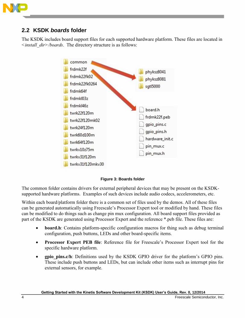
4. When the build is complete, IAR shows this information in the Build window:
Figure 10: Demo built successfully
3.3 Run a demo application
To download and run the application, perform these steps:
1. Reference the table in Appendix B to determine the debug interface that comes loaded on your
specific hardware platform.
For boards with CMSIS-DAP/mbed interfaces, visit
www.developer.mbed.org/handbook/Windows-serial-configuration and follow the
instructions to install the Windows® operating system serial driver.
For boards with P&E Micro interfaces, visit www.pemicro.com/support/downloads_find.cfm
and download the P&E Hardware Interface Drivers package.
2. Connect the development platform to your PC via USB cable between the OpenSDA USB
connector (may be named OSJTAG for some boards) and the PC USB connector.

Getting Started with the Kinetis Software Development Kit (KSDK) User’s Guide, Rev. 0, 12/2014
Freescale Semiconductor, Inc. 11
3. Open the terminal application on the PC, such as PuTTY or TeraTerm, and connect to the debug
COM port (to determine the COM port number, refer to Appendix A). Configure the terminal
with these settings:
a. 115200 baud rate
b. No parity
c. 8 data bits
d. 1 stop bit
Figure 11: Terminal (PuTTy) configuration
4. Click the “Download and Debug” button to download the application to the target.
Figure 12: Download and Debug button

Getting Started with the Kinetis Software Development Kit (KSDK) User’s Guide, Rev. 0, 12/2014
12 Freescale Semiconductor, Inc.
5. The application is then downloaded to the target and automatically runs to the main() function:
Figure 13: Stop at main() when running debugging
6. Run the code by clicking the “Go” button to start the application.
Figure 14: Go button
7. The hello_world application is now be running and a banner is displayed on the terminal. If this
is not the case, check your terminal settings and connections.
Figure 15: Text display of the hello_world demo
Getting Started with the Kinetis Software Development Kit (KSDK) User’s Guide, Rev. 0, 12/2014
Freescale Semiconductor, Inc. 13
4 Run a demo using Keil® MDK/μVision®
This section describes the steps required to build, run, and debug demo applications provided in the
Kinetis SDK. This section also shows how to build the necessary library that the demos use. The
hello_world demo application targeted for the FRDM-K64F Freedom hardware platform is used as an
example.
4.1 Install CMSIS device pack
After the MDK tools are installed, Cortex Microcontroller Software Interface Standard (CMSIS) device
packs must be installed to fully support the device from a debug perspective. These packs include things
such as memory map information, register definitions and flash programming algorithms. Follow these
steps to install the appropriate CMSIS pack.
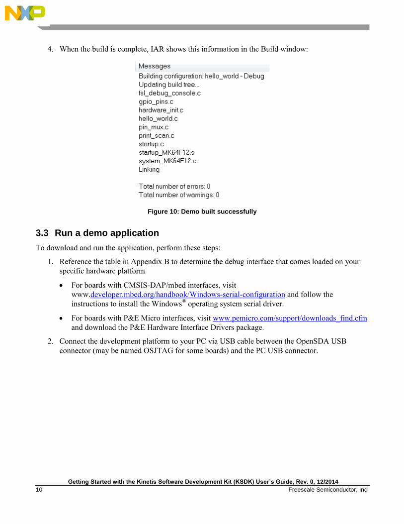
1. Open the MDK IDE, which is called μVision. In the IDE, select the “Pack Installer” icon.
Figure 16: Launch the Pack Installer
2. In the Pack Installer window, navigate to the section with the Kinetis packs (they are in
alphabetical order). The Kinetis packs start with “Keil::Kinetis” and are followed by the MCU
family name, for example “Keil::Kinetis_K60_DFP”. Because this example uses the FRDM-
K64F platform, the K60 family pack is selected. Click on the “Install” button next to the pack.
This process requires an internet connection to successfully complete.
Figure 17: Install Kinetis pack
3. After the installation finishes, close the Pack Installer window and return to the μVision IDE.

Getting Started with the Kinetis Software Development Kit (KSDK) User’s Guide, Rev. 0, 12/2014
14 Freescale Semiconductor, Inc.
4.2 Build the platform library
These steps show how to open the demo workspace in μVision, how to build the platform library
required by the demo, and how to build the demo application.
1. Demo workspace files can be found using this path:
<install_dir>/demos/<demo_name>/<toolchain>/<hardware_platform>
The workspace file is named <demo_name>.uvmpw. For this specific example, the actual path
is:
<install_dir>/demos/hello_world/mdk/frdmk64f/hello_world.uvmpw
After the workspace is open, two projects show up: one for the KSDK platform library, and one
for the demo. By default, the demo project is selected as the active project.
Figure 18: Workspace view
Getting Started with the Kinetis Software Development Kit (KSDK) User’s Guide, Rev. 0, 12/2014
Freescale Semiconductor, Inc. 15
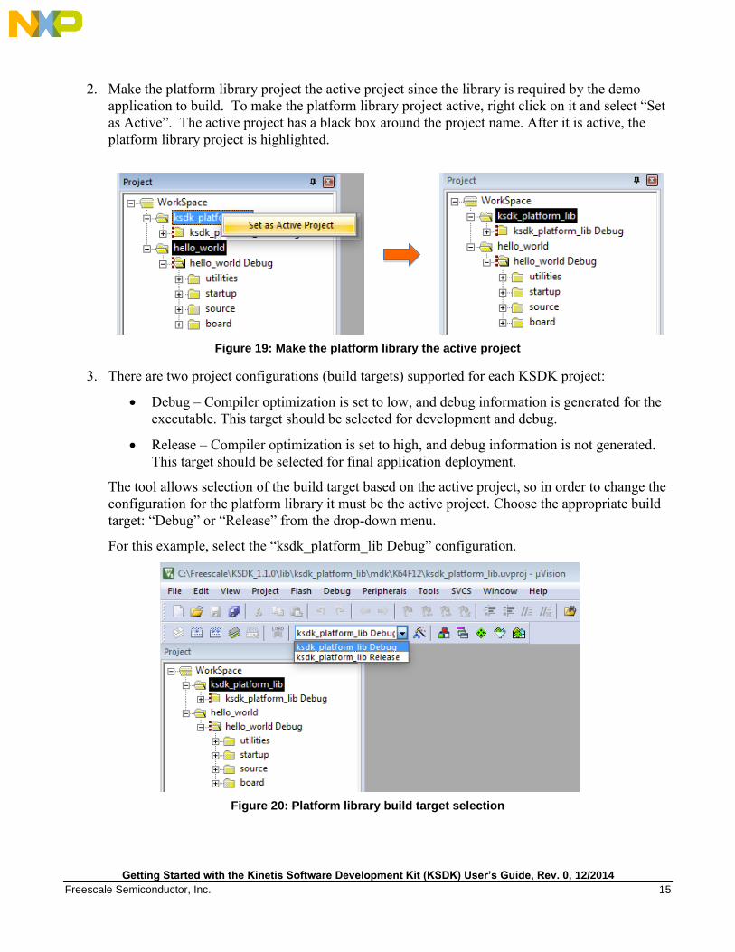
2. Make the platform library project the active project since the library is required by the demo
application to build. To make the platform library project active, right click on it and select “Set
as Active”. The active project has a black box around the project name. After it is active, the
platform library project is highlighted.
Figure 19: Make the platform library the active project
3. There are two project configurations (build targets) supported for each KSDK project:
Debug – Compiler optimization is set to low, and debug information is generated for the
executable. This target should be selected for development and debug.
Release – Compiler optimization is set to high, and debug information is not generated.
This target should be selected for final application deployment.
The tool allows selection of the build target based on the active project, so in order to change the
configuration for the platform library it must be the active project. Choose the appropriate build
target: “Debug” or “Release” from the drop-down menu.
For this example, select the “ksdk_platform_lib Debug” configuration.
Figure 20: Platform library build target selection

Getting Started with the Kinetis Software Development Kit (KSDK) User’s Guide, Rev. 0, 12/2014
16 Freescale Semiconductor, Inc.
4. Rebuild the project files by left-clicking the “Rebuild” button, highlighted in red.
Figure 21: Build the platform library
5. When the build is complete, the library (libksdk_platform.lib) is generated in this directory
according to the build target:
<install_dir>/lib/ksdk_platform_lib/mdk/<device_name>/debug
<install_dir>/lib/ksdk_platform_lib/mdk/<device_name>/release
4.3 Build a demo application
The KSDK demo applications are built upon the software building blocks provided in the Kinetis SDK
platform library, built in the previous section. If the platform library is not present, the linker displays an
error indicating that it cannot find the library. If the platform library binary is not built and present,
follow the steps in Section 4.2 to build it. Otherwise, continue with the following steps to build the
desired demo application.
1. If not already done, open the desired demo application workspace in:
<install_dir>/demos/<demo_name>/mdk/<hardware_platform>
The workspace file is named <demo_name>.uvmpw, so for this specific example, the actual path
is:
<install_dir>/demos/hello_world/iar/frdmk64f/hello_world.uvmpw

Getting Started with the Kinetis Software Development Kit (KSDK) User’s Guide, Rev. 0, 12/2014
Freescale Semiconductor, Inc. 17
2. Make the demo the active project.
Figure 22: Make the demo project the active project
3. To build the demo project, select the “Rebuild” button, highlighted in red.
Figure 23: Build the demo
4. When the build is complete, this information is shown in the Build Output window:
Figure 24: Demo built successfully
4.4 Run a demo application
To download and run the application, perform these steps:
1. Reference the table in Appendix B to determine the debug interface that comes loaded on your
specific hardware platform.
For boards with the CMSIS-DAP/mbed interface, visit
developer.mbed.org/handbook/Windows-serial-configuration and follow the instructions
to install the Windows operating system serial driver.
For boards with a P&E Micro interface, visit
www.pemicro.com/support/downloads_find.cfm and download and install the P&E
Hardware Interface Drivers package.

Getting Started with the Kinetis Software Development Kit (KSDK) User’s Guide, Rev. 0, 12/2014
18 Freescale Semiconductor, Inc.
2. Connect the development platform to your PC via USB cable between the OpenSDA USB
connector (may be named OSJTAG on some boards) and the PC USB connector.
3. Open the terminal application on the PC, such as PuTTY or TeraTerm, and connect to the debug
serial port number (to determine the COM port number, refer to Appendix A). Configure the
terminal with these settings:
a. 115200 baud rate
b. No parity
c. 8 data bits
d. 1 stop bit
Figure 25: Terminal (PuTTY) configurations

Getting Started with the Kinetis Software Development Kit (KSDK) User’s Guide, Rev. 0, 12/2014
Freescale Semiconductor, Inc. 19
4. After the application is properly build, click the “Download” button to download the application
to the target.
Figure 26: Download button
5. After clicking the “Download” button, the application downloads to the target and should be
running. To debug the application, click the “Start/Stop Debug Session” button, highlighted in
red.
Figure 327: Stop at main() when run debugging

Getting Started with the Kinetis Software Development Kit (KSDK) User’s Guide, Rev. 0, 12/2014
20 Freescale Semiconductor, Inc.
6. Run the code by clicking the “Run” button to start the application.
Figure 28: Go button
The hello_world application is now running and a banner is displayed on the terminal. If this is
not the case, check your terminal settings and connections.
Figure 29: Text display of the hello_world demo

Getting Started with the Kinetis Software Development Kit (KSDK) User’s Guide, Rev. 0, 12/2014
Freescale Semiconductor, Inc. 21
5 Run a demo using Kinetis Design Studio IDE
This section describes the steps required to configure Kinetis Design Studio (KDS) IDE to build, run,
and debug demo applications and the necessary libraries provided in the KSDK. The hello_world demo
application targeted for the FRDM-K64F Freedom hardware platform is used as an example.
5.1 Select the workspace location
The first time that KDS IDE launches, it prompts the user to select a workspace location. KDS IDE is
built on top of Eclipse, which uses workspace to store information about its current configuration, and in
some cases, source files for the projects in the workspace. The location of the workspace can be
anywhere, but it is recommended that the workspace be outside of the KSDK tree.
5.2 Install Eclipse update
Before using KDS IDE with KSDK, the KSDK Eclipse Update must be applied. Without this update,
Eclipse cannot generate KSDK-compatible projects.
5.2.1 Windows operating system instructions
To install the update, follow these instructions:
1. Select “Help -> Install New Software”.
Figure 30: Install new software

Getting Started with the Kinetis Software Development Kit (KSDK) User’s Guide, Rev. 0, 12/2014
22 Freescale Semiconductor, Inc.
2. In the Install New Software dialog box, click the “Add” button in the upper right corner. Then, in
the Add Repository dialog, select the “Archive” button.
Figure 31: Add repository for new software
3. In the Repository archive dialog box, browse the KSDK install directory.
4. Enter the <install_dir>/tools/eclipse_update folder and select the
KSDK_<version>_Eclipse_Update.zip file.
5. Click “Open”, and the “OK” button in the Add Repository dialog box.
6. The KSDK update shows up in the list of the original Install dialogs.
Figure 32: Select the Eclipse update
7. Check the box to the left of the KSDK Eclipse update and click the “Next” button in the lower
right corner.
8. Follow the remaining instructions to finish the installation of the update.
After the update is applied, restart the KDS IDE for the changes to take effect.

Getting Started with the Kinetis Software Development Kit (KSDK) User’s Guide, Rev. 0, 12/2014
Freescale Semiconductor, Inc. 23
5.2.2 Linux® OS instructions
The following instructions were performed using Ubuntu 14.04. These steps may be slightly different
for other Linux distributions.
To install the update, follow these instructions:
1. Launch KDS IDE from the command line as the root user. On the command line, use this
command, assuming the default KDS IDE install path:
user@ubuntu:~$ sudo /opt/Freescale/KDS_x.x.x/eclipse/kinetis-design-studio
The KDS IDE version (shown above as x.x.x) should reflect the version installed on your
machine, for example, 1.1.0 or 2.0.0.
2. You are prompted to enter the root password.
3. Select “Help -> Install New Software”.
Figure 33: Install new software

Getting Started with the Kinetis Software Development Kit (KSDK) User’s Guide, Rev. 0, 12/2014
24 Freescale Semiconductor, Inc.
4. In the “Install New Software” dialog box, click the “Add” button in the upper right corner. Then,
in the “Add Repository” dialog, select “Archive”.
Figure 34: Add repository for new software
5. In the Repository archive dialog box, browse the KSDK install directory.
6. Enter the <install_dir>/tools/eclipse_update folder and select the
KSDK_<version>_Eclipse_Update.zip file.
7. Click “Open”, and “OK” in the “Add Repository” dialog box.
8. The KSDK update shows up in the list of the original Install dialogs.
Figure 35: Select the Eclipse update
9. Check the box to the left of the KSDK Eclipse update and click the “Next” button in the lower
right corner.
10. Follow the remaining instructions to finish the installation of the update.

Getting Started with the Kinetis Software Development Kit (KSDK) User’s Guide, Rev. 0, 12/2014
Freescale Semiconductor, Inc. 25
11. After the update is applied, restart the KDS IDE for the changes to take effect.
12. After KDS IDE restarts, shut down the IDE and restart by launching KDS IDE as the non-root
user. To do this, follow the command in step 1, only without the “sudo” command.
5.3 Build the platform library
These steps show how to open and build the platform library project in KDS IDE. The platform library
is required by the demo and does not build without it.
NOTE
The steps required for the Linux operating system are identical to those for
the Windows operating system. The only difference is that the IDE looks
slightly different.
1. Select “File->Import” from the KDS IDE menu. In the window that appears, expand the
“General” folder and select “Existing Projects into Workspace”. Then, click the “Next” button.
Figure 36: Selection of the correct import type in KDS IDE
Getting Started with the Kinetis Software Development Kit (KSDK) User’s Guide, Rev. 0, 12/2014
26 Freescale Semiconductor, Inc.
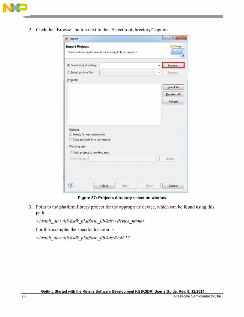
2. Click the “Browse” button next to the “Select root directory:” option.
Figure 37: Projects directory selection window
3. Point to the platform library project for the appropriate device, which can be found using this
path:
<install_dir>/lib/ksdk_platform_lib/kds/<device_name>
For this example, the specific location is:
<install_dir>/lib/ksdk_platform_lib/kds/K64F12

Getting Started with the Kinetis Software Development Kit (KSDK) User’s Guide, Rev. 0, 12/2014
Freescale Semiconductor, Inc. 27
4. After pointing to the correct directory, your “Import Projects” window should look like the
figure below. Click the “Finish” button.
Figure 38: Select K64F12 platform library project
5. There are two project configurations (build targets) supported for each KSDK project:
Debug – Compiler optimization is set to low, and debug information is generated for the
executable. This target should be selected for development and debug.
Release – Compiler optimization is set to high, and debug information is not generated. This
target should be selected for final application deployment.

Getting Started with the Kinetis Software Development Kit (KSDK) User’s Guide, Rev. 0, 12/2014
28 Freescale Semiconductor, Inc.
6. Choose the appropriate build target, “Debug” or “Release”, by clicking the downward facing
arrow next to the hammer icon, as shown below. For this example, select the “Debug” target.
Figure 39: Selection of the build target in KDS IDE
The library starts building after the build target is selected. To rebuild the library in the future,
click the hammer icon (assuming the same build target is chosen).
5.4 Build a demo application
To build a demo application, repeat the steps listed in Section 5.3, using a demo application project
instead of the platform library project. Demo application projects are located in this folder:
<install_dir>/demos/<demo name>/kds/<hardware_platform>
For this example, the path is:
<install_dir>/demos/hello_world/kds/frdmk64f
5.5 Run a demo application
NOTE
The steps required for the Linux operating system are identical to those for
the Windows operating system. The only difference is that the IDE looks
slightly different. Any platform-specific steps are listed accordingly.
To download and run the application, perform these steps:
1. Reference the table in Appendix B to determine the debug interface that comes loaded on your
specific hardware platform.
For boards with the CMSIS-DAP/mbed interface, visit
developer.mbed.org/handbook/Windows-serial-configuration and follow the instructions
to install the Windows operating system serial driver. If running on Linux OS, this step is
not required.
For boards with a P&E Micro interface, visit
www.pemicro.com/support/downloads_find.cfm and download and install the P&E
Hardware Interface Drivers package.

Getting Started with the Kinetis Software Development Kit (KSDK) User’s Guide, Rev. 0, 12/2014
Freescale Semiconductor, Inc. 29
If J-Link is used, either a standalone debug pod or OpenSDA, visit
www.segger.com/jlink-software.html.
2. Connect the development platform to your PC via USB cable between the OpenSDA USB
connector (may be named OSJTAG for some boards) and the PC USB connector.
3. In the Windows operating system environment, open the terminal application on the PC, such as
PuTTY or TeraTerm, and connect to the debug serial port number (to determine the COM port
number, refer to Appendix A). For Linux OS, open your terminal application and connect to the
appropriate device.
Configure the terminal with these settings:
a. 115200 baud
b. No parity
c. 8 data bits
d. 1 stop bit
Figure 40: Terminal (PuTTY) configurations
4. For Linux OS users only, run the following commands in your terminal. These install libudev
onto your system, which is required by KDS IDE to launch the debugger.
user@ubuntu:~$ sudo apt-get install libudev-dev libudev1

Getting Started with the Kinetis Software Development Kit (KSDK) User’s Guide, Rev. 0, 12/2014
30 Freescale Semiconductor, Inc.
user@ubuntu:~$ sudo ln –s /usr/lib/x86_64-linux-gnu/libudev.so
/usr/lib/x86_64-linux-gnu/libudev.so.0
5. Ensure that the debugger configuration is correct for the target you’re attempting to connect to.
Consult Appendix B for more information about the default debugger application on the various
hardware platforms supported by the KSDK.
a. To check the available debugger configurations, click the small downward arrow next to
the green “Debug” button and select “Debug Configurations”.
Figure 41: Debug Configurations dialog button
b. In the Debug Configurations dialog box, select debug configuration that corresponds to
the hardware platform you’re using. In this example, since the FRDM-K64F is used, the
interface to select is the CMSIS-DAP option under OpenOCD. To determine the interface
to use for other hardware platforms, refer to Appendix B.
After selecting the debugger interface, click the “Debug” button to launch the debugger.
Figure 42: Selection of the debug configuration and debugger launch

Getting Started with the Kinetis Software Development Kit (KSDK) User’s Guide, Rev. 0, 12/2014
Freescale Semiconductor, Inc. 31
6. The application is downloaded to the target and automatically run to main():
Figure 43: Stop at main() when run debugging
7. Start the application by clicking the “Resume” button:
Figure 44: Resume button
The hello_world application is now running and a banner is displayed on the terminal. If this is
not the case, check your terminal settings and connections.
Figure 45: Text display of the hello_world demo

Getting Started with the Kinetis Software Development Kit (KSDK) User’s Guide, Rev. 0, 12/2014
32 Freescale Semiconductor, Inc.
6 Run a demo using Atollic® TrueSTUDIO
®
This section describes the steps to configure Atollic TrueSTUDIO to build, run, and debug demo
applications and necessary driver libraries provided in the KSDK. The hello_world demo application
targeted for the FRDM-K64F Freedom hardware platform is used as an example.
NOTE
The Eclipse update required for the KDS IDE toolchain is not required for
Atollic.
6.1 Select the workspace location
The first time that TrueSTUDIO launches, it prompts the user to select a workspace location.
TrueSTUDIO uses Eclipse, which uses workspace to store information about its current configuration,
and in some cases, source files for the projects in the workspace. The location of the workspace can be
anywhere, but it is recommended that the workspace be outside of the KSDK tree.
6.2 Build the platform library
These steps guide you through the process of opening and building the platform library project in
TrueSTUDIO. The platform library is required by the demo and does not build without it.
1. Select “File -> Import” from the TrueSTUDIO menu. Expand the “General” folder and select
“Existing Projects into Workspace”. Then, click the “Next” button.
Figure 46: Selection of the correct import type in TrueSTUDIO

Getting Started with the Kinetis Software Development Kit (KSDK) User’s Guide, Rev. 0, 12/2014
Freescale Semiconductor, Inc. 33
2. Click the “Browse” button next to the “Select root directory:” option.
Figure 47: Projects directory selection window
3. Point to the platform library project for the appropriate device, which can be found using this
path:
<install_dir>/lib/ksdk_platform_lib/atl/<device_name>
For this example, the specific location is:
<install_dir>/lib/ksdk_platform_lib/atl/K64F12

Getting Started with the Kinetis Software Development Kit (KSDK) User’s Guide, Rev. 0, 12/2014
34 Freescale Semiconductor, Inc.
4. After pointing to the correct directory, your “Import Projects” window should look like this
figure. Click the “Finish” button.
Figure 48: Select the K64F12 platform library project
5. There are two project configurations (build targets) supported for each KSDK project:
Debug – Compiler optimization is set to low, and debug information is generated for the
executable. This target should be selected for development and debug.
Release – Compiler optimization is set to high, and debug information is not generated. This
target should be selected for final application deployment.

Getting Started with the Kinetis Software Development Kit (KSDK) User’s Guide, Rev. 0, 12/2014
Freescale Semiconductor, Inc. 35
6. Choose the appropriate build target, “Debug” or “Release”, by clicking the “Manage build
configurations” icon, as shown below. For this example, select the “Debug” target and click “Set
Active”. Since the default configuration is to use the Debugf target, there should not be a change
required.
Figure 49: Selection of build target in TrueSTUDIO
7. Click the “Build” icon to build the library.
Figure 50: Build the library
6.3 Build a demo application
To build a demo application, repeat the steps listed in section 6.2, using a demo application project
instead of the platform library project. Demo application projects are located in this folder:
<install_dir>/demos/<demo name>/atl/<hardware_platform>
For this example, the path is:
<install_dir>/demos/hello_world/atl/frdmk64f
6.4 Run a demo application
The Atollic tools require either a J-Link or P&E Micro debug interface. As a result, some hardware
platforms require an update to the OpenSDA debug firmware found on the board. To determine the
default debug interface of your board, see Appendix B. If the default interface is not J-Link or P&E
Micro, see Appendix C for instructions on how to install one of these debug interfaces.
This section describes steps to run a demo application using a J-Link debugger, although the P&E Micro
interface is also supported.
In order to perform this exercise with the J-Link interface, two things must be done:
Getting Started with the Kinetis Software Development Kit (KSDK) User’s Guide, Rev. 0, 12/2014
36 Freescale Semiconductor, Inc.
Install the J-Link software (drivers and utilities), which can be downloaded from
segger.com/downloads.html.
Make sure that either:
o The OpenSDA interface on your board is programmed with the J-Link OpenSDA
firmware. To determine if your board supports OpenSDA, refer to Appendix B. For
instructions on reprogramming the OpenSDA interface, refer to Appendix C. If your
board does not support OpenSDA, then a standalone J-Link pod is required.
o A standalone J-Link pod is connected to the debug interface of your board. Note that
some hardware platforms require hardware modification in order to function correctly
with an external debug interface.
The P&E Micro interface can also be used. To use this interface:
Install the P&E Micro Hardware Interface Drivers, which can be downloaded from
www.pemicro.com/support/downloads_find.cfm.
If your board does not come loaded with a P&E Micro interface, if supported, reprogram the
OpenSDA interface with P&E Micro OpenSDA firmware. To determine if your board supports
OpenSDA, refer to Appendix B. For instructions on reprogramming the OpenSDA interface,
refer to Appendix C.
After the debug interface is configured and ready to use, to download and run the application, perform
these steps:
1. Connect the development platform to your PC via USB cable between the OpenSDA USB
connector (may be named OSJTAG for some boards) and the PC USB connector.

Getting Started with the Kinetis Software Development Kit (KSDK) User’s Guide, Rev. 0, 12/2014
Freescale Semiconductor, Inc. 37
2. Open the terminal application on the PC, such as PuTTY or TeraTerm, and connect to the debug
serial port number (to determine the COM port number, refer to Appendix A). Configure the
terminal with these settings:
a. 115200 baud rate
b. No parity
c. 8 data bits
d. 1 stop bit
Figure 51: Terminal (PuTTY) configurations
3. Ensure that the debugger configuration is correct for the target you’re attempting to connect to.
a. To check the debugger configurations, click the “Configure Debug” icon.
Figure 52: Debug configurations dialog button

Getting Started with the Kinetis Software Development Kit (KSDK) User’s Guide, Rev. 0, 12/2014
38 Freescale Semiconductor, Inc.
b. In the Debug Configurations window, select debug configuration that corresponds to the
hardware platform you’re using. The Atollic tools require either a J-Link or P&E Micro
debug interface, so some hardware platforms require an update to the OpenSDA debug
firmware. To determine the default debug interface of your board, refer to Appendix B. If
the default interface is not J-Link or P&E Micro, refer to Appendix C for instructions on
how to install one of these debug interfaces.
Important: This example assumes the J-Link interface has been installed on the FRDM-
K64F Freescale Freedom development board platform.
c. Select the J-Link “Debug” interface and click the “Debug” button.
Figure 53: Selection of debug configuration in Debug Configuration dialog box

Getting Started with the Kinetis Software Development Kit (KSDK) User’s Guide, Rev. 0, 12/2014
Freescale Semiconductor, Inc. 39
4. The application is downloaded to the target and automatically runs to main():
Figure 54: Stop at main() when run debugging
5. Run the code by clicking the “Resume” button to start the application.
Figure 55: Resume button
The hello_world application is now running and a banner is displayed on the terminal. If this is
not the case, check your terminal settings and connections.
Figure 56: Text display of the hello_world demo

Getting Started with the Kinetis Software Development Kit (KSDK) User’s Guide, Rev. 0, 12/2014
40 Freescale Semiconductor, Inc.
7 Run a demo using ARM® GCC
This section describes the steps to configure the command line ARM GCC tools to build, run, and debug
demo applications and necessary driver libraries provided in the KSDK. The hello_world demo
application targeted for the FRDM-K64F Freedom hardware platform is used as an example.
7.1 Set up toolchain
This section contains the steps to install the necessary components required to build and run a KSDK
demo application with the ARM GCC toolchain, as supported by the KSDK. There are many ways to
use ARM GCC tools, but this example focuses on a Windows operating system environment. Though
not discussed here, ARM GCC tools can also be used with both Linux OS and Mac OSX.
7.1.1 Install GCC ARM Embedded tool chain
Download and run the installer from launchpad.net/gcc-arm-embedded. This is the actual toolset (i.e.
compiler, linker, etc.).
7.1.2 Install MinGW
The Minimalist GNU for Windows (MinGW) development tools provide a set of tools that are not
dependent on third party C-Runtime DLLs (such as Cygwin). The build environment used by the KSDK
does not utilize the MinGW build tools, but does leverage the base install of both MinGW and MSYS.
MSYS provides a basic shell with a Unix-like interface and tools.
1. Download the latest MinGW mingw-get-setup installer from
sourceforge.net/projects/mingw/files/Installer/.
2. Run the installer. The recommended installation path is C:\MinGW, however, you may install to
any location.
NOTE
The installation path cannot contain any spaces.
3. Ensure that the “mingw32-base” and “msys-base” are selected under Basic Setup.
Figure 57: Setup MinGW and MSYS

Getting Started with the Kinetis Software Development Kit (KSDK) User’s Guide, Rev. 0, 12/2014
Freescale Semiconductor, Inc. 41
4. Click “Apply Changes” in the “Installation” menu and follow the remaining instructions to
complete the installation.
Figure 58: Complete MinGW and MSYS installation
5. Add the appropriate item to the Windows operating system Path environment variable. It can be
found under Control Panel -> System and Security -> System -> Advanced System Settings in
the "Environment Variables..." section. The path is:
<mingw_install_dir>\bin
Assuming the default installation path, C:\MinGW, an example is shown below. If the path is not
set correctly, the toolchain does not work.
Note
If you have "C:\MinGW\msys\x.x\bin" in your PATH variable (as
required by KSDK 1.0.0), remove it to ensure that the new GCC build
system works correctly.

Getting Started with the Kinetis Software Development Kit (KSDK) User’s Guide, Rev. 0, 12/2014
42 Freescale Semiconductor, Inc.
Figure 59: Add Path to systems environment

Getting Started with the Kinetis Software Development Kit (KSDK) User’s Guide, Rev. 0, 12/2014
Freescale Semiconductor, Inc. 43
7.1.3 Add a new system environment variable for ARMGCC_DIR
Create a new system environment variable and name it ARMGCC_DIR. The value of this variable should point to
the ARM GCC Embedded tool chain installation path, which, for this example, is:
C:\Program Files (x86)\GNU Tools ARM Embedded\4.8 2014q3
Reference the installation folder of the GNU ARM GCC Embedded tools for the exact path name of your
installation.
Figure 60: Add ARMGCC_DIR system variable
7.1.4 Install CMake
1. Download CMake 3.0.x from www.cmake.org/cmake/resources/software.html.

Getting Started with the Kinetis Software Development Kit (KSDK) User’s Guide, Rev. 0, 12/2014
44 Freescale Semiconductor, Inc.
2. Install CMake, ensuring that the option "Add CMake to system PATH" is selected when
installing. It’s up to the user to select whether it’s installed into the PATH for all users or just the
current user. In this example, the assumption is that it’s installed for all users.
Figure 61: Install CMake
3. Follow the remaining instructions of the installer.
4. You may need to reboot your system for the PATH changes to take effect.
7.2 Build the platform library
To build the platform library, follow these instructions:
1. Open a GCC ARM Embedded tool chain command window. To launch the window, from the
Windows operating system Start menu, go to “Programs -> GNU Tools ARM Embedded
<version>” and select “GCC Command Prompt”.
Figure 62: Launch command prompt
2. Change the directory of the command window to the platform library directory in the KSDK:
<install_dir>/lib/ksdk_platform_lib/armgcc/<device_name>/

Getting Started with the Kinetis Software Development Kit (KSDK) User’s Guide, Rev. 0, 12/2014
Freescale Semiconductor, Inc. 45
3. There are two project configurations (build targets) supported for each KSDK project:
Debug – Compiler optimization is set to low, and debug information is generated for the
executable. This target should be selected for development and debug.
Release – Compiler optimization is set to high, and debug information is not generated. This
target should be selected for final application deployment.
There are batch files provided to build both configurations. For this example, the “Debug” target
is built and “build_debug.bat” is typed on the command line. If the “Release” target is desired,
type the “build_release.bat” instead.
Alternatively, if using the command line is not desired, you can double click on the batch files
from Windows operating system Explorer.
Figure 63: Build debug version of platform library
4. When the build finishes, the output looks like the image below.
Figure 64: KSDK platform library build successful
5. The library (libksdk_platform.a) is generated in one of these directories, according to the build
target:
<install_dir>/lib/ksdk_platform_lib/armgcc/<device_name>/debug
<install_dir>/lib/ksdk_platform_lib/armgcc/<device_name>/release

Getting Started with the Kinetis Software Development Kit (KSDK) User’s Guide, Rev. 0, 12/2014
46 Freescale Semiconductor, Inc.
7.3 Build a demo application
KSDK demo applications require that the platform library for the same build target (Debug or Release)
is present. Please ensure that you follow the steps in section 7.2 prior to attempting to build a demo
application.
To build a demo application, follow these steps.
1. If not already running, open a GCC ARM Embedded tool chain command window. To launch
the window, from the Windows operating system Start menu, go to “Programs -> GNU Tools
ARM Embedded <version>” and select “GCC Command Prompt”.
Figure 65: Launch command prompt
2. Change the directory to the demo application project directory, which has a path like this:
<install_dir>/demos/<demo_name>/armgcc/<hardware_platform>
For this example, the exact path is:
<install_dir>/demos/hello_world/armgcc/frdmk64f
3. Type “build_debug.bat” on the command line or double click on the "build_debug.bat" file in
Windows operating system Explorer to perform the build. The output is shown in this figure:
Figure 66: hello_world demo build successful
7.4 Run a demo application
This section describes steps to run a demo application using the J-Link GDB Server application. To
perform this exercise, two things must be done:
Install the J-Link software (drivers and utilities), which can be downloaded from
www.segger.com/downloads.html.
Make sure that either:
o The OpenSDA interface on your board is programmed with the J-Link OpenSDA
firmware. To determine if your board supports OpenSDA, refer to Appendix B. For

Getting Started with the Kinetis Software Development Kit (KSDK) User’s Guide, Rev. 0, 12/2014
Freescale Semiconductor, Inc. 47
instructions on reprogramming the OpenSDA interface, refer to Appendix C. If your
board does not support OpenSDA, then a standalone J-Link pod is required.
o You have a standalone J-Link pod that is connected to the debug interface of your board.
Note that some hardware platforms require hardware modification in order to function
correctly with an external debug interface.
After the J-Link interface is configured and connected, follow these steps to download and run the demo
application:
1. Connect the development platform to your PC via USB cable between the OpenSDA USB
connector (may be named OSJTAG for some boards) and the PC USB connector. If using a
standalone J-Link debug pod, also connect it to the SWD/JTAG connector of the board.
2. Open the terminal application on the PC, such as PuTTY or TeraTerm, and connect to the debug
serial port number (to determine the COM port number, refer to Appendix A). Configure the
terminal with these settings:
e. 115200 baud rate
f. No parity
g. 8 data bits
h. 1 stop bit
Figure 67: Terminal (PuTTY) configurations

Getting Started with the Kinetis Software Development Kit (KSDK) User’s Guide, Rev. 0, 12/2014
48 Freescale Semiconductor, Inc.
3. Open the J-Link GDB Server application. Assuming the J-Link software is installed, the
application can be launched by going to the Windows operating system Start menu and selecting
“Programs -> SEGGER -> J-Link <version> J-Link GDB Server”.
4. Modify the settings as shown below. The target device selection chosen for this example is the
“MK64FN1M0xxx12”.
Figure 68: Segger J-Link GDB Server configuration

Getting Started with the Kinetis Software Development Kit (KSDK) User’s Guide, Rev. 0, 12/2014
Freescale Semiconductor, Inc. 49
5. After it is connected, the screen should resemble this figure:
Figure 69: Segger J-Link GDB Server screen after successful connection
6. If not already running, open a GCC ARM Embedded tool chain command window. To launch
the window, from the Windows operating system Start menu, go to “Programs -> GNU Tools
ARM Embedded <version>” and select “GCC Command Prompt”.
Figure 70: Launch command prompt
7. Change to the directory that contains the demo application output. The output can be found in
using one of these paths, depending on the build target selected:
<install_dir/demos/<demo_name>/armgcc/<hardware_platform>/debug
<install_dir/demos/<demo_name>/armgcc/<hardware_platform>/release
For this example, the path is:
<install_dir>/demos/hello_world/armgcc/frdmk64f/debug

Getting Started with the Kinetis Software Development Kit (KSDK) User’s Guide, Rev. 0, 12/2014
50 Freescale Semiconductor, Inc.
8. Run the command “arm-none-eabi-gdb.exe <demo_name>.elf”. For this example, it is “arm-
none-eabi-gdb.exe hello_world.elf”.
Figure 71: Run arm-none-eabi-gdb
9. Run these commands:
a. “target remote localhost:2331”
b. “monitor reset”
c. “monitor halt”
d. “load”
e. “monitor reset”
10. The application is now downloaded and halted at the reset vector. Execute the “monitor go”
command to start the demo application.
The hello_world application is now running and a banner is displayed on the terminal. If this is
not the case, check your terminal settings and connections.
Figure 72: Text display of the hello_world demo
Getting Started with the Kinetis Software Development Kit (KSDK) User’s Guide, Rev. 0, 12/2014
Freescale Semiconductor, Inc. 51
Appendix A – How to determine COM port
This section describes the steps necessary to determine the debug COM port number of your Freescale
hardware development platform. All Freescale boards ship with a factory programmed, on-board debug
interface, whether it’s based on OpenSDA or the legacy P&E Micro OSJTAG interface. To determine
what your specific board ships with, reference Appendix B.
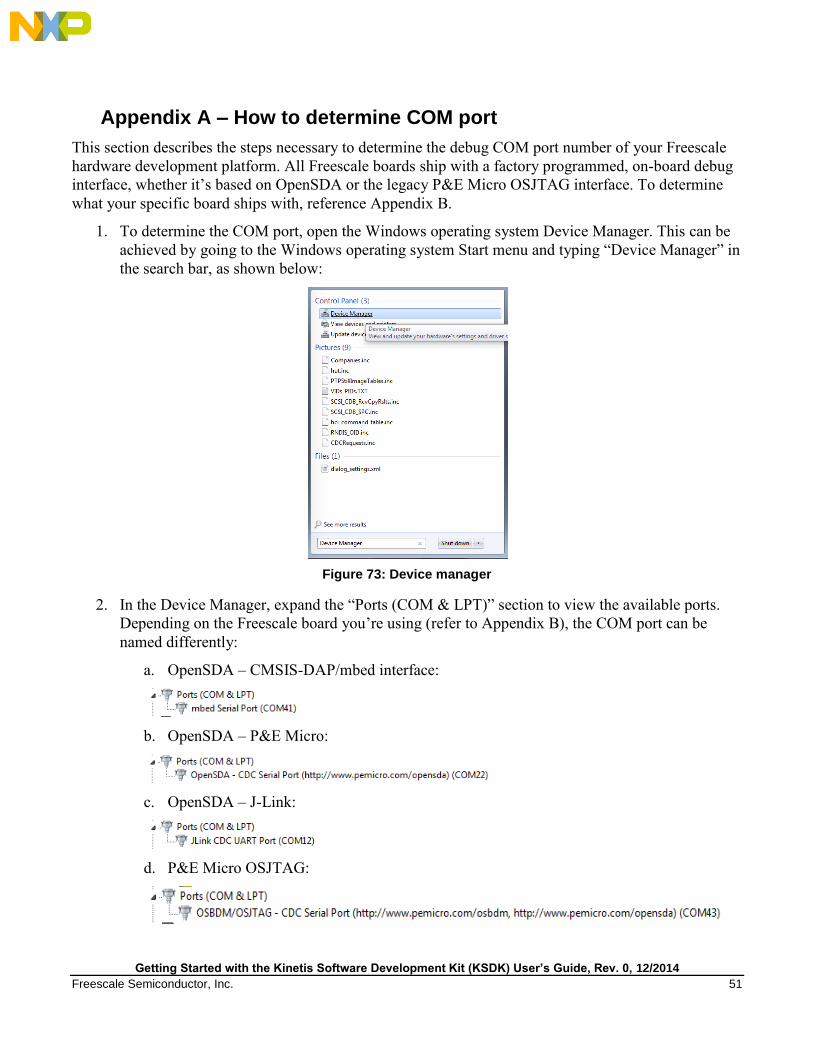
1. To determine the COM port, open the Windows operating system Device Manager. This can be
achieved by going to the Windows operating system Start menu and typing “Device Manager” in
the search bar, as shown below:
Figure 73: Device manager
2. In the Device Manager, expand the “Ports (COM & LPT)” section to view the available ports.
Depending on the Freescale board you’re using (refer to Appendix B), the COM port can be
named differently:
a. OpenSDA – CMSIS-DAP/mbed interface:
b. OpenSDA – P&E Micro:
c. OpenSDA – J-Link:
d. P&E Micro OSJTAG:

Getting Started with the Kinetis Software Development Kit (KSDK) User’s Guide, Rev. 0, 12/2014
52 Freescale Semiconductor, Inc.
Appendix B – Default debug interfaces
The Kinetis SDK supports various Kinetis hardware platforms that come loaded with a variety of factory
programmed debug interface configurations. The following table lists the hardware platforms supported
by the KSDK, their default debug interface, and any version information that helps differentiate a
specific interface configuration.
All recent and future Freescale hardware platforms support the configurable OpenSDA standard.
Table 1 Hardware platforms supported by KSDK
Hardware Platform Default Interface OpenSDA Details
FRDM-K22F CMSIS-DAP\mbed OpenSDA OpenSDA v2.1
FRDM-K64F CMSIS-DAP\mbed OpenSDA OpenSDA v2.0
FRDM-KL03Z P&E Micro OpenSDA OpenSDA v1.0
FRDM-KL46Z P&E Micro OpenSDA OpenSDA v1.0
TWR-K22F120M P&E Micro OpenSDA OpenSDA v1.0
TWR-K24F120M P&E Micro OpenSDA OpenSDA v1.0
TWR-K60D100M P&E Micro OSJTAG N/A
TWR-K64F120M P&E Micro OpenSDA OpenSDA v1.0
TWR-KV10Z32 P&E Micro OpenSDA OpenSDA v1.0
TWR-KV31F120M P&E Micro OpenSDA OpenSDA v1.0

Getting Started with the Kinetis Software Development Kit (KSDK) User’s Guide, Rev. 0, 12/2014
Freescale Semiconductor, Inc. 53
Appendix C – Updating OpenSDA firmware
Any Freescale hardware platform that comes with an OpenSDA-compatible debug interface has the
ability to update the OpenSDA firmware. This typically means switching from the default application
(either CMSIS-DAP/mbed or P&E Micro) to a Segger J-Link. This section contains the steps to switch
the OpenSDA firmware to a J-Link interface. However, the steps can be applied to also restoring the
original image.
For reference, OpenSDA firmware files can be found at the links below:
J-Link: Download appropriate image from www.segger.com/opensda.html. Chose the
appropriate J-Link binary based on the table in Appendix B. Any OpenSDA v1.0 interface
should use the standard OpenSDA download (i.e. the one with no version). For OpenSDA 2.0 or
2.1, select the corresponding binary.
CMSIS-DAP/mbed: This interface is provided to support the ARM mbed initiative. Navigate to
developer.mbed.org/platforms and select your hardware platform. On the specific platform/board
page, there is a link to the firmware image and instructions on how to load it, though the
instructions are the same as below.
P&E Micro: Downloading P&E Micro OpenSDA firmware images requires registration with
P&E Micro (www.pemicro.com).
These steps show how to update the OpenSDA firmware on your board.
1. Unplug the board’s USB cable.
2. Press the board’s “Reset” button. While still holding the button, plug the board back in to the
USB cable.
3. When the board re-enumerates, it shows up as a disk drive called “BOOTLOADER”.
Figure 74: BOOTLOADER drive

Getting Started with the Kinetis Software Development Kit (KSDK) User’s Guide, Rev. 0, 12/2014
54 Freescale Semiconductor, Inc.
4. Drag the new firmware image onto the BOOTLOADER drive in Windows operating system
Explorer, similar to how you would drag and drop a file onto a normal USB flash drive.
5. Power cycle the board and it re-enumerates as the new debug interface type.
NOTE
If for any reason the firmware update fails, the board can always re-enter
bootloader mode by holding down the “Reset” button and power cycling.

Getting Started with the Kinetis Software Development Kit (KSDK) User’s Guide, Rev. 0, 12/2014
Freescale Semiconductor, Inc. 55
8 Revision history
This table summarizes the revisions made to this document.
Table 2 Revision History
Revision number Date Substantive changes
0 12/2014 Initial release

Document Number: KSDKGSUG
Rev. 0
12/2014
How to Reach Us:
Home Page:
freescale.com
Web Support:
freescale.com/support
Information in this document is provided solely to enable system and software implementers to use Freescale products. There are no express or implied copyright licenses granted hereunder to design or fabricate any integrated circuits based on the information in this document.
Freescale reserves the right to make changes without further notice to any products herein. Freescale makes no warranty, representation, or guarantee regarding the suitability of its products for any particular purpose, nor does Freescale assume any liability arising out of the application or use of any product or circuit, and specifically disclaims any and all liability, including without limitation consequential or incidental damages. “Typical” parameters that may be provided in Freescale data sheets and/or specifications can and do vary in different applications, and actual performance may vary over time. All operating parameters, including “typicals,” must be validated for each customer application by customer’s technical experts. Freescale does not convey any license under its patent rights nor the rights of others. Freescale sells products pursuant to standard terms and conditions of sale, which can be found at the following address: freescale.com/SalesTermsandConditions.
Freescale, the Freescale logo, and Kinetis are trademarks of Freescale Semiconductor, Inc., Reg. U.S. Pat. & Tm. Off. All other product or service names are the property of their respective owners. ARM, ARM powered logo, Keil, μVision, and Cortex are registered trademarks of ARM Limited (or its subsidiaries) in the EU and/or elsewhere. mbed is a trademark of ARM Limited (or its subsidiaries) in the EU and/or elsewhere. All rights reserved.
© 2014 Freescale Semiconductor, Inc.