Getting Started With HawkEye 1600T e
81
Getting Started With SIMATIC HawkEye™ 1600T EM-40265-1V37 v3.7, Nov 2007
description
Siemens
Transcript of Getting Started With HawkEye 1600T e

Getting Started With SIMATIC HawkEye™ 1600T
EM-40265-1V37
v3.7, Nov 2007

Safety GuidelinesThis manual contains notices you have to observe in order to ensure your personal safety, as well as to prevent damage to property. The notices referring to your personal safety are highlighted in the manual by a safety alert symbol, notices referring to property damage only have no safety alert symbol. The notices shown below are graded according to the degree of danger.
If more than one degree of danger is present, the warning notice representing the highest degree of danger will be used. A notice warning of injury to persons with a safety alert symbol may also include a warning relating to property damage.
Dangerindicates that death or severe personal injury will result if proper precautions are not taken.
Warningindicates that death or severe personal injury may result if proper precautions are not taken.
Cautionwith a safety alert symbol indicates that minor personal injury can result if proper precautions are not taken.
Cautionwithout a safety alert symbol indicates that property damage can result if proper precautions are not taken.
Noticeindicates that an unintended result or situation can occur if the corresponding notice is not taken into account.

Qualified PersonnelThe device/system may only be set up and used in conjunction with this documentation. Commissioning and operation of a device/system may only be performed by qualified personnel. Within the context of the safety notices in this documentation qualified persons are defined as persons who are authorized to commission, ground and label devices, systems and circuits in accordance with established safety practices and standards.
Prescribed UsageNote the following:
TrademarksAll names identified by ® are registered trademarks of the Siemens AG.
The remaining trademarks in this publication may be trademarks whose use by third parties for their own purposes could violate the rights of the owner.
Disclaimer of LiabilityWe have reviewed the contents of this publication to ensure consistency with the hardware and software described. Since variance cannot be precluded entirely, we cannot guarantee full consistency. However, the information in this publication is reviewed regularly and any necessary corrections are included in subsequent editions.
Siemens AGAutomation and DrivesPostfach 484890437 NÜRNBERGGERMANY
12/2006
Copyright © Siemens AG 2006 Technical data subject to change
WarningThis device and its components may only be used for the applications described in the catalog or the technical description, and only in connection with devices or components from other manufacturers which have been approved or recommended by Siemens. Correct, reliable operation of the product requires proper transport, storage, positioning and assembly as well as careful operation and maintenance.


Contents
Safety Guidelines iiQualified Personnel iiiPrescribed Usage iiiTrademarks iiiDisclaimer of Liability iii
PREFACE Welcome! vii
Purpose of This Manual viiFurther Support viiTraining Center viii
SITRAIN™ Siemens Training viii
Technical Support viiiService & Support on the Internet viiiManual Conventions ix
CHAPTER 1 Using HawkEye 1600T for the First Time 1-1
Establishing a Network Connection & Making a FrontRunner™ Device Button for Your Camera 1-1Creating a New Job to Acquire Images 1-5
v3.7, Nov 2007 Getting Started With SIMATIC HawkEye™ 1600T v

Contents
CHAPTER 2 The 1600T in Action - Simple Examples 2-1
Icons 2-2Simple Blob Tool 2-3Simple Flaw Tool 2-12Simple Fast Edge Tool 2-18Simple Data Matrix Tool 2-34
Training Tools 2-39
Where To Now? 2-40
CHAPTER 3 The 1600T in Action - Advanced Example 3-1
Advanced Example Using Multiple Tools 3-2Input Datums 3-2Procedure 3-2
Where To Now? 3-21
Index Index-1
vi Getting Started With SIMATIC HawkEye™ 1600T v3.7, Nov 2007

Preface
PREFACE Welcome!
Purpose of This ManualThis manual is designed to get you up and running with your SIMATIC HawkEye™ 1600T Smart Camera quickly and confidently.
Please don’t be intimidated by the size of this Getting Started manual. It contains a large number of images that will help you as you create new Jobs using the tutorials.
Further SupportIf you have any questions concerning the use of products which are not answered in this manual, please contact your local Siemens partner at your Siemens office.
You can find your local partner at:
http://www.siemens.com/automation/partner
You can find a guide to the technical documentation on offer for the individual SIMATIC products and systems at:
http://www.siemens.de/simatic-tech-doku-portal
You can find the catalog and online ordering systems at:
http://mall.automation.siemens.com/
v3.7, Nov 2007 Getting Started With SIMATIC HawkEye™ 1600T vii

Preface
Training Center
SITRAIN™ Siemens TrainingSiemens Training (SITRAIN) offers a range of courses on Machine Vision and Symbology Reading. Training classes are conducted in Norcross, Georgia and at locations across the USA. SITRAIN also offers courses on PLC, Drives, Controls, HMI, NET, Process Control, Analyzers and Instrumentation, Electrical and Power, Safety and more. Details of current SITRAIN course offerings can be viewed at http://www.automation.usa.siemens.com/sitrain/
For training in Germany, see: http://www.sitrain.siemens.com/html_76/f_11_sensors.html
To view Machine Vision and Symbology course offerings, please click on the “Automation” link in the middle of the page and then the “Vision and Sensors” link from the list that is presented. Alternatively, please contact the Siemens Training Registrar at (800) 241-4453.
Technical SupportHow to reach technical support for all A&D products
• With the Support Request form on the Web:http://www.siemens.de/automation/support-request
• Telephone: + 49 180 5050 222
• Telephone: 800 333-7421 (USA)
• Fax: + 49 180 5050 223
Further information about our technical support is available in the Internet at http://www.siemens.com/automation/service
Service & Support on the InternetThe Siemens Service & Support team provides you with comprehensive additional information on SIMATIC products in its online Internet services.
http://www.siemens.com/automation/service&support
viii Getting Started With SIMATIC HawkEye™ 1600T v3.7, Nov 2007

There you can find:
• Current product information and downloads which you may find useful for your product.
• The documents you require, using our Service & Support search engine.
• A forum where users and experts from all over the world exchange ideas.
• Your local partner for Automation & Drives.
• Information about onsite services, repairs, spare parts. Lots more is available to you on our “Service“ pages.
Manual ConventionsThe following typographical conventions are used throughout this manual.
• Items emphasizing important information are bolded.
• Menu selections, menu items and entries in screen images are indicated as: Run (triggered), Modify..., etc.
v3.7, Nov 2007 Getting Started With SIMATIC HawkEye™ 1600T ix

Preface
x Getting Started With SIMATIC HawkEye™ 1600T v3.7, Nov 2007

1
Usi
ng
Haw
kEye
160
0T
for
the
Fir
st T
ime
1
CHAPTER 1 Using HawkEye 1600T for the First Time
Before proceeding with this chapter, you should have:
• Completed installation of the SIMATIC Visionscape® software (see Chapter 3 of Getting Started With SIMATIC Visionscape® Framegrabber Boards)
• Suitably mounted and wired the SIMATIC HawkEye™ 1600T Smart Camera (see Chapter 2 of SIMATIC HawkEye™ 1600T Smart Camera Guide)
Establishing a Network Connection & Making a FrontRunner™ Device Button for Your Camera
This section assumes familiarity with basic wired networking concepts such as IP addresses and DHCP servers. If these terms are not familiar, please talk to your IT department and see “Setting Up Network Communications” in the SIMATIC HawkEye™ 1600T Smart Camera Guide.
A network connection is required to communicate with the SIMATIC HawkEye™ 1600T. In order that the SIMATIC HawkEye™ 1600T be recognized, it must have a valid IP address. As shipped, the SIMATIC HawkEye™ 1600T will try to obtain an IP address from a DHCP server so, if your network is configured for DHCP, you will be able to connect to your camera without changing any settings. However, if your network requires a static IP
v3.7, Nov 2007 Getting Started With SIMATIC HawkEye™ 1600T 1-1

Chapter 1 Using HawkEye 1600T for the First Time
address to be assigned, or if you would like to use a cross-link cable, please see “Setting Up Network Communications” in the SIMATIC HawkEye™ 1600T Smart Camera Guide.
Note: When using SIMATIC HawkEye™ 1600T in a production environment, the HE1600T Smart Camera MUST be programmed to use a static IP address instead of DHCP. This is to prevent loss of communications due to IP lease renewal by the DHCP server.
Follow these steps when connecting the SIMATIC HawkEye™ 1600T for the first time:
1. Connect the SIMATIC HawkEye™ 1600T to the same network as the PC that will be running the FrontRunner™ software.
2. Apply power to the SIMATIC HawkEye™ 1600T; be sure to do this AFTER making the physical connection to the network.
3. Start the FrontRunner™ application by selecting Start > SIMATIC > SIMATIC Visionscape > Visionscape FrontRunner. The main FrontRunner™ screen is displayed, as shown in Figure 1–1.
FIGURE 1–1. FrontRunner™ Main Screen
4. Select View > Network Overview to display the Network Overview window, as shown in Figure 1–2.
Device ButtonsDevice BarToolbar
1-2 Getting Started With SIMATIC HawkEye™ 1600T v3.7, Nov 2007

Establishing a Network Connection & Making a FrontRunner™
Usi
ng
Haw
kEye
160
0T
for
the
Fir
st T
ime
1
FIGURE 1–2. Network Overview Screen — No Camera Selected
Your camera should appear in the network overview list. The camera name will be of the form HawkeyeXXXXXX, where the X’s represent the last part of the camera’s MAC address.
5. Click on the row that lists your camera. The network information area should update and display the Change Network Settings … button, as shown in Figure 1–3.
FIGURE 1–3. Network Overview Screen — Camera Selected
6. If the info area displays a red background identifying a camera communication problem, it means that the camera and the PC, even though connected to the same network, are not using the same logical IP addressing. See “Setting Up Network Communications” in the SIMATIC HawkEye™ 1600T Smart Camera Guide to correct the communication problem.
7. Click the Change Network Settings button, which displays the login screen. Enter the default user name (hawkeye) and password (“vision”) and click OK. You will see the Change HawkEye Network Settings dialog box (Figure 1–4), which allows you to change the name of your camera.
v3.7, Nov 2007 Getting Started With SIMATIC HawkEye™ 1600T 1-3
Chapter 1 Using HawkEye 1600T for the First Time
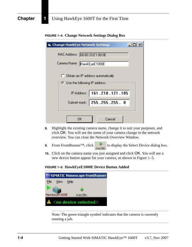
FIGURE 1–4. Change Network Settings Dialog Box
8. Highlight the existing camera name, change it to suit your purposes, and click OK. You will see the name of your camera change in the network overview. You can close the Network Overview Window.
9. From FrontRunner™, click to display the Select Device dialog box.
10. Click on the camera name you just assigned and click OK. You will see a new device button appear for your camera, as shown in Figure 1–5.
FIGURE 1–5. HawkEyeE1000E Device Button Added
Note: The green triangle symbol indicates that the camera is currently running a job.
1-4 Getting Started With SIMATIC HawkEye™ 1600T v3.7, Nov 2007

Creating a New Job to Acquire Images
Usi
ng
Haw
kEye
160
0T
for
the
Fir
st T
ime
1
11. From this point on, you can simply click on the device button for your camera to establish a connection.
Creating a New Job to Acquire ImagesThe instructions that the SIMATIC HawkEye™ 1600T camera performs in a particular application are called “Steps”, and the complete collection of steps is called a “Job”. To do anything, even to take a picture, the SIMATIC HawkEye™ 1600T requires a Job. Use the following procedure to create a new Job:
1. Click the device button for your camera.
2. Take control of the camera by clicking .
This will display the Login to Device dialog box, where you should enter the username (hawkeye) and password (“vision”) and then click OK.
3. To begin creating a new Job, select File > New Job (or click ).
FrontRunner™ displays the screen shown in Figure 1–6.
FIGURE 1–6. FrontRunner Main Screen After Clicking New Job
Acquire New Image
Live Video
v3.7, Nov 2007 Getting Started With SIMATIC HawkEye™ 1600T 1-5

Chapter 1 Using HawkEye 1600T for the First Time
4. To acquire a new image, click You should see an image appear in the display area.
5. To display a “live” image, click (Click it again to exit live video.)
6. To bring up the step editing environment, click
You will see a hierarchy of steps on the left hand side of the editor, as shown in Figure 1–7.
FIGURE 1–7. Hierarchy of Steps
1-6 Getting Started With SIMATIC HawkEye™ 1600T v3.7, Nov 2007

Creating a New Job to Acquire Images
Usi
ng
Haw
kEye
160
0T
for
the
Fir
st T
ime
1
7. Select the step named “Acquire”. After you select the Acquire step, the right hand side of the editor will display the various parameters and settings that can be modified. Of immediate interest is Exposure Time. You can click on the spreadsheet cell with the current Exposure Time value to change it. Reducing the exposure time will darken the image, while increasing it will make the image brighter.
So far, the Job you are manipulating exists only on the PC. You are using the Job in “Setup Mode”, which allows you to create, edit, and debug Jobs on the PC.
8. To transfer the Job to the camera, click
If you want the Job to be non-volatile (still be loaded on the camera when it is rebooted), then click
9. Now that there is a Job loaded onto the camera, start it by clicking
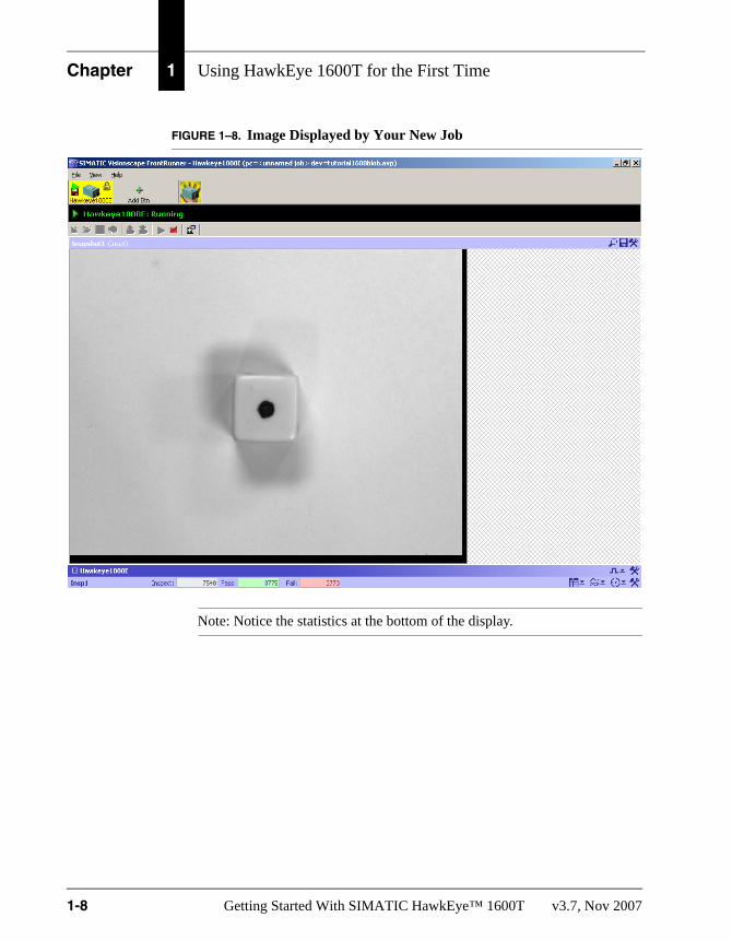
This will switch FrontRunner™ to a runtime display which, in the case of this example, will simply display the image, as shown in Figure 1–8.
v3.7, Nov 2007 Getting Started With SIMATIC HawkEye™ 1600T 1-7
Chapter 1 Using HawkEye 1600T for the First Time
FIGURE 1–8. Image Displayed by Your New Job
Note: Notice the statistics at the bottom of the display.
1-8 Getting Started With SIMATIC HawkEye™ 1600T v3.7, Nov 2007

2
Th
e 16
00T
in A
ctio
n -
S
imp
le E
xam
ple
s
2
CHAPTER 2 The 1600T in Action - Simple Examples
This chapter contains simple tutorial examples to help you become familiar with various FrontRunner™ tools:
• “Simple Blob Tool” on page 2-3
• “Simple Flaw Tool” on page 2-12
• “Simple Fast Edge Tool” on page 2-18
• “Simple Data Matrix Tool” on page 2-34
Notice that each sections lists the complete Job (xxxxx.AVP) that corresponds to the Job you will create.
v3.7, Nov 2007 Getting Started With SIMATIC HawkEye™ 1600T 2-1

Chapter 2 The 1600T in Action - Simple Examples
IconsTable 2–1 describes the icon used in this chapter:
TABLE 2–1. Icons and What They Mean
Icon What It Means
This is step #1 of a procedure.
Click the left mouse button.
This is step #2 of a procedure.
Click the left mouse button.
1
2
2-2 Getting Started With SIMATIC HawkEye™ 1600T v3.7, Nov 2007

Simple Blob Tool
Th
e 16
00T
in A
ctio
n -
S
imp
le E
xam
ple
s
2
Simple Blob ToolFrontRunner™ Job:Start > SIMATIC > SIMATIC Visionscape > Visionscape Tutorials & Samples > Tutorials > HawkEye 1600T > Simple Blob Tool > tutorial_blob.avp
The Blob Tool performs connectivity analysis on an image, finding groups of connected pixels with gray levels above or below a threshold. Each group is called a blob. The Blob Tool records all the detected blobs into a blob tree. For each blob, the tool calculates many geometric features including the length, width, area, etc. In addition, the number of blobs and number of parts in the region of interest (ROI) are calculated. A part is a blob that has the opposite color of the background. A hole is a blob with the same color as the background.
This example counts the number of pips on a die.
1. Start FrontRunner™ by selecting Start > SIMATIC > SIMATIC Visionscape > Visionscape FrontRunner. FrontRunner™ displays its main window.
2. Do either of the following:
a. For a camera already added to FrontRunner™, simply click the camera button.
b. For a camera that has not been added to FrontRunner™, click
FrontRunner™ displays the Select Device dialog box. Select a camera and click OK.
3. Take control of the camera by clicking . FrontRunner™ displays the Login to Device dialog box.
Note: You will not see this screen if no login parameters are set.
4. Enter your username (defaults is “hawkeye”) and password (default is “vision”), and click OK.
5. Stop the camera by clicking . FrontRunner™ displays the Device State Changed dialog box. Because we’re creating a new Job, click No.
6. Start creating a new Job by clicking Create New Program, and then Editor, as shown in Figure 2–1.
v3.7, Nov 2007 Getting Started With SIMATIC HawkEye™ 1600T 2-3

Chapter 2 The 1600T in Action - Simple Examples
FIGURE 2–1. Start Creating New Job
The camera will change to Edit Mode (indicated by the pencil next to the camera icon).
Note: Maximize or minimize the Editor as needed.
7. In the left pane, highlight Acquire in the Step Tree.
Note: You may have to click the Acquire tab in the properties window.
FrontRunner™ displays the Acquire properties page.
8. Adjust the following Acquire properties:
– Picture Mode — Set to Load Images from File.
– File List — Click <empty>, and then Add... to display the Open dialog box. Browse for the file Die 1 Pip.tif from Windows. It’s located at:
C:\Vscape\Tutorials & Samples\Tutorials\HawkEye 1600T\Simple Blob Tool
Select Die 1 Pip.tif and click Open.
Note: These files were installed from the installation CD onto your hard drive when you installed SIMATIC Visionscape®. If you installed SIMATIC Visionscape® to a location other than C:\vscape, replace it with the appropriate drive and directory designation.
9. Highlight Snapshot in the Step Tree. Right click Snapshot and click Insert Into. FrontRunner™ displays the Insert Step window. Double click on Blob Tool to insert it into the Snapshot.
1
2
2-4 Getting Started With SIMATIC HawkEye™ 1600T v3.7, Nov 2007

Simple Blob Tool
Th
e 16
00T
in A
ctio
n -
S
imp
le E
xam
ple
s
2
10. In the left pane, highlight Blob Filter in the Step Tree. Right click BlobFilter and click Delete. FrontRunner™ displays the Are you sure you want to delete this step? screen. Click Yes.
Note: Normally, you wouldn’t delete Blob Filter from your Job. But, since we’re simply counting pips on a die, you can delete it in this Job.
11. Click Blob Tool in the Step Tree to display the Blob Tool properties page.
12. Adjust the following Blob Tool properties:
– Use Autothreshold — Uncheck it.
– High Threshold — Set to 64.
– Maximum Blob size — Set to 10000.
– Min Number of Blobs — Set to 1.
– Max Number of Blobs — Set to 6.
13. To display Die 1 Pip.tif, click .
FrontRunner™ displays the image and a box (the Blob Tool ROI), as shown in Figure 2–2.
v3.7, Nov 2007 Getting Started With SIMATIC HawkEye™ 1600T 2-5

Chapter 2 The 1600T in Action - Simple Examples
FIGURE 2–2. Die 1 Pip.tif & Blob Tool ROI
14. Click on the box. Move and size the box so that it surrounds the die, as shown in Figure 2–3.
2-6 Getting Started With SIMATIC HawkEye™ 1600T v3.7, Nov 2007

Simple Blob Tool
Th
e 16
00T
in A
ctio
n -
S
imp
le E
xam
ple
s
2
FIGURE 2–3. Blob Tool ROI Moved & Sized15. To run the job once and then stop, click .
The Job passes.
16. In the left pane of the Editor, highlight Acquire.
FrontRunner™ displays the Acquire properties page.
17. Adjust the following Acquire properties:
– File List — Click to the right of File List, and then click Add.... Browse for the files Die 2 Pip.tif, Die 3 Pip.tif, Die 4 Pip.tif, Die 5 Pip.tif, and Die 6 Pip.tif from Windows. They are located at:
C:\Vscape\Tutorials & Samples\Tutorials\HawkEye 1600T\Simple Blob Tool
18. Select Die 2 Pip.tif through Die 6 Pip.tif and click Open.
19. Minimize the Editor.
20. To run the job once and then stop, click .
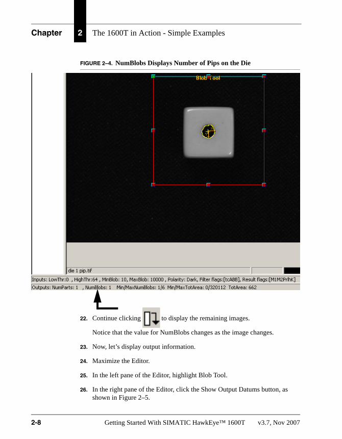
21. Notice that NumBlobs matches the number of pips on the die, as shown in Figure 2–4.
v3.7, Nov 2007 Getting Started With SIMATIC HawkEye™ 1600T 2-7
Chapter 2 The 1600T in Action - Simple Examples
FIGURE 2–4. NumBlobs Displays Number of Pips on the Die
22. Continue clicking to display the remaining images.
Notice that the value for NumBlobs changes as the image changes.
23. Now, let’s display output information.
24. Maximize the Editor.
25. In the left pane of the Editor, highlight Blob Tool.
26. In the right pane of the Editor, click the Show Output Datums button, as shown in Figure 2–5.
2-8 Getting Started With SIMATIC HawkEye™ 1600T v3.7, Nov 2007

Simple Blob Tool
Th
e 16
00T
in A
ctio
n -
S
imp
le E
xam
ple
s
2
FIGURE 2–5. Show Output Datums Button27. Click to the left of all the output datums (5 of the 6 output datums have already been selected in Figure 2–5).
28. Close or minimize the Editor.
29. Click the Download Program from PC to Device (Figure 2–6) to download your Job to the Smart Camera.
FIGURE 2–6. Download Program from PC to Device Button
30. Click the Start Program on Device (Figure 2–7) to start your Job on the Smart Camera.
FIGURE 2–7. Start Program on Device Button
v3.7, Nov 2007 Getting Started With SIMATIC HawkEye™ 1600T 2-9

Chapter 2 The 1600T in Action - Simple Examples
31. To display the output datums you specified earlier, click the button shown in Figure 2–8.
FIGURE 2–8. Show Output Datums Button
You will see output similar to that shown in Figure 2–9:
2-10 Getting Started With SIMATIC HawkEye™ 1600T v3.7, Nov 2007

Simple Blob Tool
Th
e 16
00T
in A
ctio
n -
S
imp
le E
xam
ple
s
2
FIGURE 2–9. Output From Your JobCongratulations! You’ve just created a SIMATIC Visionscape® Job that counts the pips on a die and displays output information.
v3.7, Nov 2007 Getting Started With SIMATIC HawkEye™ 1600T 2-11
Chapter 2 The 1600T in Action - Simple Examples
Simple Flaw ToolFrontRunner™ Job:Start > SIMATIC > SIMATIC Visionscape > Visionscape Tutorials & Samples > Tutorials > HawkEye 1600T > Simple Flaw Tool > tutorial_flaw.avp
The Flaw Tool detects the presence or absence of a feature. For example, it can determine whether a package has any defects in appearance, such as cracks or scratches. The input to the Flaw Tool is an image buffer on which to process. The output of the step at runtime is the pass/fail status of the inspection. An output containing the resulting sum or count is also available.
This example determines the presence or absence of a paper clip.
1. Start FrontRunner™ by selecting Start > SIMATIC > SIMATIC Visionscape > Visionscape FrontRunner. FrontRunner™ displays its main window.
2. Do either of the following:
a. For a camera already added to FrontRunner™, simply click the camera button.
b. For a camera that has not been added to FrontRunner™, click
FrontRunner™ displays the Select Device dialog box. Select a camera and click OK.
3. Take control by clicking . FrontRunner™ displays the Login to Device dialog box.
Note: You will not see this screen if no login parameters are set.
4. Enter your username and password (the defaults are “hawkeye” and “vision”).
5. Click OK.
6. Stop the camera by clicking .
FrontRunner™ displays the Device State Changed dialog box.
7. Because we’re creating a new Job, click No.
2-12 Getting Started With SIMATIC HawkEye™ 1600T v3.7, Nov 2007

Simple Flaw Tool
Th
e 16
00T
in A
ctio
n -
S
imp
le E
xam
ple
s
2
8. Start creating a new Job by clicking .The camera will change to Edit Mode (indicated by the pencil next to the camera icon).
9. To display the Step Tree and Editor, click .
This allows you to view your Job as you create it.
Note: Maximize or minimize the Editor as needed to accomplish the steps in this procedure.
10. Highlight Acquire in the Step Tree (left pane).
Note: You may have to click the Acquire tab in the properties window.
FrontRunner™ displays the Acquire properties page.
11. Adjust the following Acquire properties:
– Picture Mode — Set to Load Images from File.
– File List — Click <empty>, and then Add... to display the Open dialog box. Browse for the files Paperclip01.tif, Paperclip02.tif and Paperclip03.tif from Windows. They are located at:
C:\Vscape\Tutorials & Samples\Tutorials\HawkEye 1600T\Simple Flaw Tool
Select Paperclip01.tif, Paperclip02.tif, and Paperclip03.tif. Click Open.
Note: These files were installed from the installation CD onto your hard drive when you installed SIMATIC Visionscape®. If you installed SIMATIC Visionscape® to a location other than C:\vscape, replace it with the appropriate drive and directory designation.
12. Highlight Snapshot in the Step Tree (left pane). Right click Snapshot and click Insert Into. FrontRunner™ displays the Insert Step window. Click on the Analysis Tools tab. Double click on Flaw Tool to insert it into the Snapshot.
v3.7, Nov 2007 Getting Started With SIMATIC HawkEye™ 1600T 2-13

Chapter 2 The 1600T in Action - Simple Examples
13. Highlight Flaw Tool in the Step Tree (left pane) to display the Flaw Tool properties page.
14. Adjust the following Flaw Tool properties:
– Tool Method — Count Edge Pixels
– Min Allowed Edge Count — 100
– Max Allowed Edge Count — 5000
– Graphics Level — Show Details
15. In the Setup window, to view Paperclip01.tif, click .
FrontRunner™ displays the image Paperclip01.tif and a box, as shown in Figure 2–10.
FIGURE 2–10. Paperclip01.tif and Flaw Tool Displayed
16. Click on the box; re-size it so that it is just slightly smaller than the entire display area (see Figure 2–11).
17. To run the Job once and then stop, click .
FrontRunner™ displays Paperclip02 and the information that the Flaw Tool passed, as shown in Figure 2–11.
2-14 Getting Started With SIMATIC HawkEye™ 1600T v3.7, Nov 2007

Simple Flaw Tool
Th
e 16
00T
in A
ctio
n -
S
imp
le E
xam
ple
s
2
FIGURE 2–11. Paperclip 02 Passes InspectionNotice the following properties and their values:
– Edge Count — 1672
– Min Allowed — 100
– Max Allowed — 5000
The inspection passed because the Edge Count was between the minimum and maximum allowed.
18. Click again.
FrontRunner™ displays the empty window and the information that the Flaw Tool failed, as shown in Figure 2–12.
v3.7, Nov 2007 Getting Started With SIMATIC HawkEye™ 1600T 2-15

Chapter 2 The 1600T in Action - Simple Examples
FIGURE 2–12. Paperclip 03 Fails Inspection
Notice the following properties and their values:
– Edge Count — 7
– Min Allowed — 100
– Max Allowed — 5000
The inspection failed because the Edge Count was not within the minimum and maximum allowed.
19. Click again.
2-16 Getting Started With SIMATIC HawkEye™ 1600T v3.7, Nov 2007

Simple Flaw Tool
Th
e 16
00T
in A
ctio
n -
S
imp
le E
xam
ple
s
2
FrontRunner™ displays Paperclip01 and the information that the Flaw Tool passed, as shown in Figure 2–13.FIGURE 2–13. Paperclip 01 Passes Inspection
Notice the following properties and their values:
– Edge Count — 2262
– Min Allowed — 100
– Max Allowed — 5000
The inspection passed because the Edge Count was between the minimum and maximum allowed.
v3.7, Nov 2007 Getting Started With SIMATIC HawkEye™ 1600T 2-17

Chapter 2 The 1600T in Action - Simple Examples
Simple Fast Edge ToolFrontRunner™ Job:Start > SIMATIC > SIMATIC Visionscape > Visionscape Tutorials & Samples > Tutorials > HawkEye 1600T > Simple Fast Edge Tool > tutorial_fastedge.avp
The Fast Edge Tool finds straight edges or line segments in the ROI. The step calculates a line equation, a midpoint of the line and angle, as well as statistics for the edges found as they relate to the line that is fit.
The Fast Edge Tool searches the ROI for places where gray level changes occur and uses these places to compute a line based on one of three types of line fit algorithms. These transitions are found using a threshold or gradient analysis.
This example finds the four edges and two top corners of one image.
1. Start FrontRunner™ by selecting Start > SIMATIC > SIMATIC Visionscape > Visionscape FrontRunner. FrontRunner™ displays its main window.
2. Do either of the following:
a. For a camera already added to FrontRunner™, simply click the camera button.
b. For a camera that has not been added to FrontRunner™, click .
FrontRunner™ displays the Select Device dialog box. Select a camera and click OK.
3. Take control by clicking . FrontRunner™ displays the Login to Device dialog box.
Note: You will not see this screen if no login parameters are set.
4. Enter your username and password (the defaults are “hawkeye” and “vision”).
5. Click OK.
6. Stop the camera by clicking .
FrontRunner™ displays the Device State Changed dialog box.
2-18 Getting Started With SIMATIC HawkEye™ 1600T v3.7, Nov 2007

Simple Fast Edge Tool
Th
e 16
00T
in A
ctio
n -
S
imp
le E
xam
ple
s
2
7. Because we’re creating a new Job, click No.8. Start creating a new Job by clicking .
The camera will change to Edit Mode (indicated by the pencil next to the camera icon).
9. To display the Step Tree, click .
This allows you to view your Job as you create it.
Note: Maximize or minimize the Editor as needed to accomplish the steps in this procedure.
10. Highlight Acquire in the Step Tree (left pane). FrontRunner™ displays the Acquire properties page.
Note: You may have to click the Acquire tab in the properties window.
11. Adjust the following Acquire properties:
– Picture Mode — Set to Load Images from File.
– File List — Click <empty>, and then Add... to display the Open dialog box. Browse for the file Chip01.tif from Windows. It is located at:
C:\Vscape\Tutorials & Samples\Tutorials\HawkEye 1600T\Simple Fast Edge Tool
Select Chip01.tif. Click Open.
Note: This file was installed from the installation CD onto your hard drive when you installed SIMATIC Visionscape®. If you installed SIMATIC Visionscape® to a location other than C:\vscape, replace it with the appropriate drive and directory designation.
12. Highlight Snapshot in the Step Tree (left pane). Right click Snapshot and click Insert Into. FrontRunner™ displays the Insert Step window. Click on the Analysis Tools tab. Double click on Fast Edge Tool to insert it into the Snapshot.
v3.7, Nov 2007 Getting Started With SIMATIC HawkEye™ 1600T 2-19

Chapter 2 The 1600T in Action - Simple Examples
13. Highlight Fast Edge in the Step Tree (left pane), right click, and then click Rename. Rename it to Top Fast Edge.
14. In the Setup window, to view Chip01.tif, click . FrontRunner™ displays Chip01.tif, as shown in Figure 2–14.
FIGURE 2–14. Chip01.tif with One Fast Edge Tool Inserted
15. Adjust the ROI for Top Fast Edge so that it looks like the image in Figure 2–15.
2-20 Getting Started With SIMATIC HawkEye™ 1600T v3.7, Nov 2007

Simple Fast Edge Tool
Th
e 16
00T
in A
ctio
n -
S
imp
le E
xam
ple
s
2
FIGURE 2–15. Chip01.tif with One Fast Edge Tool Adjusted16. Highlight Top Fast Edge in the Step Tree (left pane).
17. Adjust the following Top Fast Edge properties:
– Scan Direction — Set to Top to Bottom
– Transition color — Set to Light to Dark
– Gradient Threshold — Set to 50
18. Highlight Snapshot in the Step Tree (left pane). Right click Snapshot and click Insert Into. FrontRunner™ displays the Insert Step window. Double click on Fast Edge Tool to insert a second one into the Snapshot.
19. Highlight the second Fast Edge in the Step Tree (left pane), right click, and then click Rename. Rename it to Left Fast Edge.
20. Adjust the ROI for Left Fast Edge so that it looks like the image in Figure 2–16.
v3.7, Nov 2007 Getting Started With SIMATIC HawkEye™ 1600T 2-21
Chapter 2 The 1600T in Action - Simple Examples
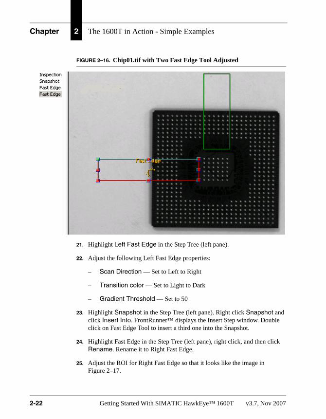
FIGURE 2–16. Chip01.tif with Two Fast Edge Tool Adjusted
21. Highlight Left Fast Edge in the Step Tree (left pane).
22. Adjust the following Left Fast Edge properties:
– Scan Direction — Set to Left to Right
– Transition color — Set to Light to Dark
– Gradient Threshold — Set to 50
23. Highlight Snapshot in the Step Tree (left pane). Right click Snapshot and click Insert Into. FrontRunner™ displays the Insert Step window. Double click on Fast Edge Tool to insert a third one into the Snapshot.
24. Highlight Fast Edge in the Step Tree (left pane), right click, and then click Rename. Rename it to Right Fast Edge.
25. Adjust the ROI for Right Fast Edge so that it looks like the image in Figure 2–17.
2-22 Getting Started With SIMATIC HawkEye™ 1600T v3.7, Nov 2007

Simple Fast Edge Tool
Th
e 16
00T
in A
ctio
n -
S
imp
le E
xam
ple
s
2
FIGURE 2–17. Chip01.tif with Three Fast Edge Tool Adjusted26. Highlight Right Fast Edge in the Step Tree (left pane).
27. Adjust the following Right Fast Edge properties:
– Scan Direction — Set to Right to Left
– Transition color — Set to Light to Dark
– Gradient Threshold — Set to 50
28. Highlight Snapshot in the Step Tree (left pane). Right click Snapshot and click Insert Into. FrontRunner™ displays the Insert Step window. Double click on Fast Edge Tool to insert a fourth one into the Snapshot.
29. Highlight Fast Edge in the Step Tree (left pane), right click, and then click Rename. Rename it to Bottom Fast Edge.
30. Adjust the ROI for Bottom Fast Edge so that it looks like the image in Figure 2–18.
v3.7, Nov 2007 Getting Started With SIMATIC HawkEye™ 1600T 2-23

Chapter 2 The 1600T in Action - Simple Examples
FIGURE 2–18. Chip01.tif with Four Fast Edge Tool Adjusted
31. Highlight Bottom Fast Edge in the Step Tree (left pane).
32. Adjust the following Bottom Fast Edge properties:
– Scan Direction — Set to Bottom to Top
– Transition color — Set to Light to Dark
– Gradient Threshold — Set to 50
33. Highlight Snapshot in the Step Tree (left pane). Right click Snapshot and click Insert Into. FrontRunner™ displays the Insert Step window. Click the Measurements tab. Double click on IntersectLines Meas to insert it into the Snapshot.
34. Repeat the previous step one more time to add another IntersectLines Meas to the Job.
35. Rename the two IntersectLines Meas tools:
2-24 Getting Started With SIMATIC HawkEye™ 1600T v3.7, Nov 2007

Simple Fast Edge Tool
Th
e 16
00T
in A
ctio
n -
S
imp
le E
xam
ple
s
2
a. Highlight the first IntersectLines Meas, right click, and then clickRename. Rename the first IntersectLines Meas to Left Top IntersectLines Meas.
b. Highlight the second IntersectLines Meas, right click, and then click Rename. Rename the second IntersectLines Meas to Right Top IntersectLines Meas.
36. Highlight Snapshot in the Step Tree (left pane). Right click Snapshot and click Insert Into. FrontRunner™ displays the Insert Step window. Click the Analysis Tools tab. Double click on TwoPt Locator to insert it into the Snapshot.
When you are finished, the Job should look like the Job in Figure 2–19.
FIGURE 2–19. Step Tree
37. Highlight Left Top IntersectLines Meas in the Step Tree (left pane).
38. To select the reference for First Line, click in the area to the right of the blue arrow (Figure 2–20), and click on the three dots, which displays the Select Reference window, as shown in Figure 2–21.
v3.7, Nov 2007 Getting Started With SIMATIC HawkEye™ 1600T 2-25

Chapter 2 The 1600T in Action - Simple Examples
FIGURE 2–20. Selecting Reference for First Line
FIGURE 2–21. Select Reference Window
39. Select Edge Line:EdgeLine from Left Fast Edge.
40. Click OK.
41. To select the reference for Second Line, click in the area to the right of the blue arrow (Figure 2–22), and click on the three dots, which displays the Select Reference window, as shown in Figure 2–23.
Click Here
2-26 Getting Started With SIMATIC HawkEye™ 1600T v3.7, Nov 2007

Simple Fast Edge Tool
Th
e 16
00T
in A
ctio
n -
S
imp
le E
xam
ple
s
2
FIGURE 2–22. Selecting Reference for Second LineFIGURE 2–23. Select Reference Window
42. Select Edge Line:EdgeLine from Top Fast Edge.
43. Click OK.
44. Highlight Right Top IntersectLines Meas in the Step Tree (left pane).
45. To select the reference for First Line, click in the area to the right of the blue arrow (Figure 2–24), and click on the three dots, which displays the Select Reference window, as shown in Figure 2–25.
Click Here
v3.7, Nov 2007 Getting Started With SIMATIC HawkEye™ 1600T 2-27

Chapter 2 The 1600T in Action - Simple Examples
FIGURE 2–24. Selecting Reference for First Line
FIGURE 2–25. Select Reference Window
46. Select Edge Line:EdgeLine from Right Fast Edge.
47. Click OK.
48. To select the reference for Second Line, click in the area to the right of the blue arrow (Figure 2–26), and click on the three dots, which displays the Select Reference window, as shown in Figure 2–27.
Click Here
2-28 Getting Started With SIMATIC HawkEye™ 1600T v3.7, Nov 2007

Simple Fast Edge Tool
Th
e 16
00T
in A
ctio
n -
S
imp
le E
xam
ple
s
2
FIGURE 2–26. Selecting Reference for Second LineFIGURE 2–27. Select Reference Window
49. Select Edge Line:EdgeLine from Top Fast Edge.
50. Click OK.
51. Highlight TwoPt Locator in the Step Tree (left pane).
52. To select the reference for Pin 1 Point, click in the area to the right of the blue arrow (Figure 2–28), and click on the three dots, which displays the Select Reference window, as shown in Figure 2–29.
Click Here
v3.7, Nov 2007 Getting Started With SIMATIC HawkEye™ 1600T 2-29

Chapter 2 The 1600T in Action - Simple Examples
FIGURE 2–28. Selecting Reference for Pin 1 Point
FIGURE 2–29. Select Reference Window
53. Select Point:Pt from Left Top IntersectLines Meas.
54. Click OK.
55. To select the reference for Pin 2 Point, click in the area to the right of the blue arrow (Figure 2–30), and click on the three dots, which displays the Select Reference window, as shown in Figure 2–31.
Click Here
2-30 Getting Started With SIMATIC HawkEye™ 1600T v3.7, Nov 2007

Simple Fast Edge Tool
Th
e 16
00T
in A
ctio
n -
S
imp
le E
xam
ple
s
2
FIGURE 2–30. Selecting Reference for Pin 2 PointFIGURE 2–31. Select Reference Window
56. Select Point:Pt from Right Top IntersectLines Meas.
57. Click OK.
58. Your setup for TwoPt Locator should appear as shown in Figure 2–32.
Click Here
v3.7, Nov 2007 Getting Started With SIMATIC HawkEye™ 1600T 2-31
Chapter 2 The 1600T in Action - Simple Examples
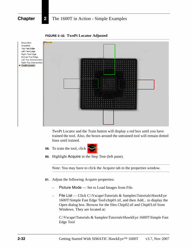
FIGURE 2–32. TwoPt Locator Adjusted
TwoPt Locator and the Train button will display a red box until you have trained the tool. Also, the boxes around the untrained tool will remain dotted lines until trained.
59. To train the tool, click .
60. Highlight Acquire in the Step Tree (left pane).
Note: You may have to click the Acquire tab in the properties window.
61. Adjust the following Acquire properties:
– Picture Mode — Set to Load Images from File.
– File List — Click C:\Vscape\Tutorials & Samples\Tutorials\HawkEye 1600T\Simple Fast Edge Tool\chip01.tif, and then Add... to display the Open dialog box. Browse for the files Chip02.tif and Chip03.tif from Windows. They are located at:
C:\Vscape\Tutorials & Samples\Tutorials\HawkEye 1600T\Simple Fast Edge Tool
2-32 Getting Started With SIMATIC HawkEye™ 1600T v3.7, Nov 2007

Simple Fast Edge Tool
Th
e 16
00T
in A
ctio
n -
S
imp
le E
xam
ple
s
2
Select Chip02.tif and Chip03.tif. Click Open.Note: This file was installed from the installation CD onto your hard drive when you installed SIMATIC Visionscape®. If you installed SIMATIC Visionscape® to a location other than C:\vscape, replace it with the appropriate drive and directory designation.
62. To run the Job once and then stop, click .
Notice that the Job runs successfully, as shown in Figure 2–33.
FIGURE 2–33. Job Runs Successfully
Note: Any tool inserted into the 2PtLocator adjusts as the symbol moves.
v3.7, Nov 2007 Getting Started With SIMATIC HawkEye™ 1600T 2-33

Chapter 2 The 1600T in Action - Simple Examples
Simple Data Matrix ToolFrontRunner™ Job:Start > SIMATIC > SIMATIC Visionscape > Visionscape Tutorials & Samples > Tutorials > HawkEye 1600T > Simple Data Matrix Tool > tutorial_datamatrix.avp
The Data Matrix Tool reads a Data Matrix symbol and converts the data to a string that can be compared to a known string, or exported. The input to DataMatrixTool consists of a matrix description, and search criteria. The output of DataMatrixTool will be the decoded string and status indicating a match with the known string.
This example reads six Data Matrices using the DataMatrix Tool.
1. Start FrontRunner™ by selecting Start > SIMATIC > SIMATIC Visionscape > Visionscape FrontRunner. FrontRunner™ displays its main window.
2. Do either of the following:
a. For a camera already added to FrontRunner™, simply click the camera button.
b. For a camera that has not been added to FrontRunner™, click .
FrontRunner™ displays the Select Device dialog box. Select a camera and click OK.
3. Take control by clicking . FrontRunner™ displays the Login to Device dialog box.
Note: You will not see this screen if no login parameters are set.
4. Enter your username and password (the defaults are “hawkeye” and “vision”).
5. Click OK.
6. Stop the camera by clicking .
FrontRunner™ displays the Device State Changed dialog box.
7. Because we’re creating a new Job, click No.
2-34 Getting Started With SIMATIC HawkEye™ 1600T v3.7, Nov 2007

Simple Data Matrix Tool
Th
e 16
00T
in A
ctio
n -
S
imp
le E
xam
ple
s
2
8. Start creating a new Job by clicking .The camera will change to Edit Mode (indicated by the pencil next to the camera icon).
9. To display the Step Tree and Editor, click .
This allows you to view your Job as you create it.
Note: Maximize or minimize the Editor as needed to accomplish the steps in this procedure.
10. Highlight Acquire in the Step Tree (left pane). FrontRunner™ displays the Acquire properties page.
Note: You may have to click the Acquire tab in the properties window.
11. Adjust the following Acquire properties:
– Picture Mode — Set to Load Images from File.
– File List — Click <empty>, and then Add... to display the Open dialog box. Browse for the file DMs.tif from Windows. It is located at:
C:\Vscape\Tutorials & Samples\Tutorials\HawkEye 1600T\Simple Data Matrix Tool
Select DMs.tif. Click Open.
Note: This file was installed from the installation CD onto your hard drive when you installed SIMATIC Visionscape®. If you installed SIMATIC Visionscape® to a location other than C:\vscape, replace it with the appropriate drive and directory designation.
12. In the Setup window, to view DMs.tif, click . FrontRunner™ displays DMs.tif, as shown in Figure 2–34.
v3.7, Nov 2007 Getting Started With SIMATIC HawkEye™ 1600T 2-35

Chapter 2 The 1600T in Action - Simple Examples
FIGURE 2–34. DMs.tif
13. Highlight Snapshot in the Step Tree (left pane). Right click Snapshot and click Insert Into. FrontRunner™ displays the Insert Step window. Click on the Analysis Tools tab. Double click on DataMatrix Tool to insert it into the Snapshot.
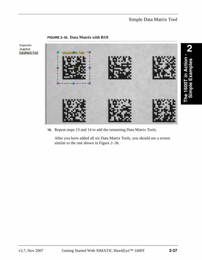
14. Adjust the ROI so that there is a generous amount of space around the Data Matrix, as shown in Figure 2–35.
2-36 Getting Started With SIMATIC HawkEye™ 1600T v3.7, Nov 2007
Simple Data Matrix Tool
Th
e 16
00T
in A
ctio
n -
S
imp
le E
xam
ple
s
2
FIGURE 2–35. Data Matrix with ROI15. Repeat steps 13 and 14 to add the remaining Data Matrix Tools.
After you have added all six Data Matrix Tools, you should see a screen similar to the one shown in Figure 2–36.
v3.7, Nov 2007 Getting Started With SIMATIC HawkEye™ 1600T 2-37

Chapter 2 The 1600T in Action - Simple Examples
FIGURE 2–36. All Six Data Matrices Trained
16. To run the Job once and then stop, click .
You should see a screen similar to the one shown in Figure 2–37.
2-38 Getting Started With SIMATIC HawkEye™ 1600T v3.7, Nov 2007

Simple Data Matrix Tool
Th
e 16
00T
in A
ctio
n -
S
imp
le E
xam
ple
s
2
FIGURE 2–37. All Trained and Inspection Run OnceTraining ToolsSome FrontRunner™ tools, such as the Data Matrix tool, can be trained, that is, told what to expect when reading. For example, if you train a Data Matrix tool to read a Data Matrix with 8 rows and 32 columns, the Data Matrix tool will fail when it tries to read something other than a Data Matrix with 8 rows and 32 columns. So, a trained tool is more restricted in what it can read; an untrained tool is less restricted in what it can read.
For this tutorial, you saw a red Train button and red boxes in front of each Data Matrix tool. Even though we didn’t train the six Data Matrix tools, they each read their respective Data Matrices without problems.
v3.7, Nov 2007 Getting Started With SIMATIC HawkEye™ 1600T 2-39

Chapter 2 The 1600T in Action - Simple Examples
Where To Now?Chapter 3 of this Getting Started contains a tutorial example that is more advanced than the ones you just finished.
2-40 Getting Started With SIMATIC HawkEye™ 1600T v3.7, Nov 2007

3
Th
e 16
00T
in A
ctio
n -
A
dvan
ced
Exa
mp
le
3
CHAPTER 3 The 1600T in Action - Advanced ExampleThis chapter contains an advanced tutorial example to help you become familiar with the use of various FrontRunner™ tools in one Job.
Notice that we list the complete Job (xxxxx.AVP) that corresponds to the Job you will create.
v3.7, Nov 2007 Getting Started With SIMATIC HawkEye™ 1600T 3-1

Chapter 3 The 1600T in Action - Advanced Example
Advanced Example Using Multiple ToolsFrontRunner™ Job:Start > SIMATIC > SIMATIC Visionscape > Visionscape Tutorials & Samples > Tutorials > HawkEye 1600T > Advanced Example Using Multiple Tools > tutorial_opto.avp
This example finds the sides of an optical isolator module, locates the switch on top of the optical isolator module, and determines the switch’s position.
Input DatumsInput datums get their values from another datum from another step. Whenever you see the icon shown in Figure 3–1, you will use the Select Reference editor to select another step in your Job that will supply the datum value for this datum.
FIGURE 3–1. Input Datum Icon
ProcedureUse the following procedure to find the sides of an opto, locate the switch on top of the opto, and determine the switch’s position:
1. Start FrontRunner™ by selecting Start > SIMATIC > SIMATIC Visionscape > Visionscape FrontRunner. FrontRunner™ displays its main window.
2. Do either of the following:
a. For a camera already added to FrontRunner™, simply click the camera button.
b. For a camera that has not been added to FrontRunner™, click .
FrontRunner™ displays the Select Device dialog box. Select a camera and click OK.
3. Take control by clicking . FrontRunner™ displays the Login to Device dialog box.
3-2 Getting Started With SIMATIC HawkEye™ 1600T v3.7, Nov 2007
Advanced Example Using Multiple Tools
Th
e 16
00T
in A
ctio
n -
A
dvan
ced
Exa
mp
le
3
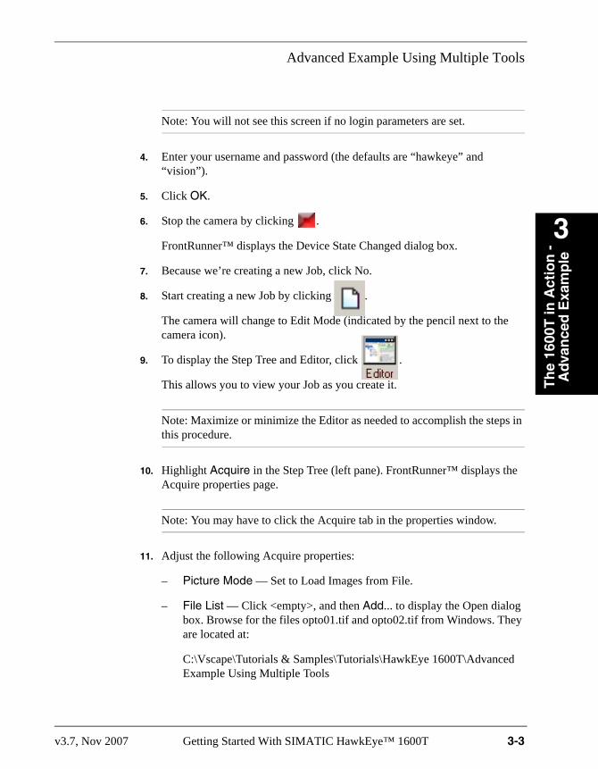
Note: You will not see this screen if no login parameters are set.
4. Enter your username and password (the defaults are “hawkeye” and “vision”).
5. Click OK.
6. Stop the camera by clicking .
FrontRunner™ displays the Device State Changed dialog box.
7. Because we’re creating a new Job, click No.
8. Start creating a new Job by clicking .
The camera will change to Edit Mode (indicated by the pencil next to the camera icon).
9. To display the Step Tree and Editor, click .
This allows you to view your Job as you create it.
Note: Maximize or minimize the Editor as needed to accomplish the steps in this procedure.
10. Highlight Acquire in the Step Tree (left pane). FrontRunner™ displays the Acquire properties page.
Note: You may have to click the Acquire tab in the properties window.
11. Adjust the following Acquire properties:
– Picture Mode — Set to Load Images from File.
– File List — Click <empty>, and then Add... to display the Open dialog box. Browse for the files opto01.tif and opto02.tif from Windows. They are located at:
C:\Vscape\Tutorials & Samples\Tutorials\HawkEye 1600T\Advanced Example Using Multiple Tools
v3.7, Nov 2007 Getting Started With SIMATIC HawkEye™ 1600T 3-3

Chapter 3 The 1600T in Action - Advanced Example
Select opto01.tif and opto02.tif. Click Open.
Note: These files were installed from the installation CD onto your hard drive when you installed SIMATIC Visionscape®. If you installed SIMATIC Visionscape® to a location other than C:\vscape, replace it with the appropriate drive and directory designation.
12. Highlight Snapshot in the Step Tree (left pane). Right click Snapshot and click Insert Into. FrontRunner™ displays the Insert Step window. Click on the Analysis Tools tab. Double click on Fast Edge to insert it into the Snapshot.
13. In the Setup window, to view opto01.tif, click .
14. FrontRunner™ displays Opto01.tif, as shown in Figure 3–2.
FIGURE 3–2. Opto01.tif
3-4 Getting Started With SIMATIC HawkEye™ 1600T v3.7, Nov 2007

Advanced Example Using Multiple Tools
Th
e 16
00T
in A
ctio
n -
A
dvan
ced
Exa
mp
le
3
15. Highlight Snapshot in the Step Tree (left pane). Right click Snapshot and click Insert Into. FrontRunner™ displays the Insert Step window. Double click on Fast Edge to insert a second Fast Edge into the Snapshot.
16. Highlight Snapshot in the Step Tree (left pane). Right click Snapshot and click Insert Into. FrontRunner™ displays the Insert Step window. Double click on Fast Edge to insert a third Fast Edge into the Snapshot.
17. Rename the three Fast Edge tools:
a. Highlight the first Fast Edge in the Step Tree (left pane), right click, and then click Rename. Rename the first Fast Edge to Left Fast Edge.
b. Highlight the second Fast Edge in the Step Tree (left pane), right click, and then click Rename. Rename the second Fast Edge to Top Fast Edge.
c. Highlight the third Fast Edge in the Step Tree (left pane), right click, and then click Rename. Rename the third Fast Edge to Right Fast Edge.
18. Adjust the three Fast Edge tools so that they look like the image in Figure 3–3.
v3.7, Nov 2007 Getting Started With SIMATIC HawkEye™ 1600T 3-5

Chapter 3 The 1600T in Action - Advanced Example
FIGURE 3–3. Opto with Three Fast Edges Adjusted
19. Highlight Left Fast Edge in the Step Tree (left pane).
20. Adjust the following Left Fast Edge properties:
– Scan Direction — Set to Left to Right
– Transition color — Set to Dark to Light
– Sharpness — Set to Sharp
21. Highlight Top Fast Edge in the Step Tree (left pane). Adjust the following Top Fast Edge properties:
– Scan Direction — Set to Top to Bottom
– Transition color — Set to Dark to Light
– Sharpness — Set to Sharp
3-6 Getting Started With SIMATIC HawkEye™ 1600T v3.7, Nov 2007

Advanced Example Using Multiple Tools
Th
e 16
00T
in A
ctio
n -
A
dvan
ced
Exa
mp
le
3
22. Highlight Right Fast Edge in the Step Tree (left pane). Adjust the following Right Fast Edge properties:
– Scan Direction — Set to Right to Left
– Transition color — Set to Dark to Light
– Sharpness — Set to Sharp
23. Highlight Snapshot in the Step Tree (left pane). Right click Snapshot and click Insert Into. FrontRunner™ displays the Insert Step window. Click the Measurements tab. Double click on IntersectLines Meas to insert it into the Snapshot.
24. Highlight Snapshot in the Step Tree (left pane). Right click Snapshot and click Insert Into. FrontRunner™ displays the Insert Step window. Double click on IntersectLines Meas to insert a second one into the Snapshot.
25. Rename the two IntersectLines Meas tools:
a. Highlight the first IntersectLines Meas, right click, and then click Rename. Rename the first IntersectLines Meas to Left Top IntersectLines Meas.
b. Highlight the second IntersectLines Meas, right click, and then click Rename. Rename the second IntersectLines Meas to Right Top IntersectLines Meas.
26. Highlight Snapshot in the Step Tree (left pane). Right click Snapshot and click Insert Into. FrontRunner™ displays the Insert Step window. Click the Analysis Tools tab. Double click on TwoPt Locator to insert it into the Snapshot.
27. Highlight TwoPt Locator in the Step Tree (left pane). Right click TwoPt Locator and click Insert Into. FrontRunner™ displays the Insert Step window. Double click on Blob Tool to insert it into the TwoPt Locator.
28. Right click on the Blob Filter and select Delete. Click yes to confirm the deletion of the Blob Filter.
When you are finished, the Job should look like the Job in Figure 3–4.
v3.7, Nov 2007 Getting Started With SIMATIC HawkEye™ 1600T 3-7

Chapter 3 The 1600T in Action - Advanced Example
FIGURE 3–4. Step Tree
29. Highlight Left Top IntersectLines Meas in the Step Tree (left pane).
30. To select the reference for First Line, click in the area to the right of the blue arrow (Figure 3–5), and click on the three dots, which displays the Select Reference window, as shown in Figure 3–6.
FIGURE 3–5. Selecting Reference for First Line
Click Here
3-8 Getting Started With SIMATIC HawkEye™ 1600T v3.7, Nov 2007

Advanced Example Using Multiple Tools
Th
e 16
00T
in A
ctio
n -
A
dvan
ced
Exa
mp
le
3
FIGURE 3–6. Select Reference Window
31. Select Edge Line:EdgeLine from Left Fast Edge.
32. Click OK.
33. To select the reference for Second Line, click in the area to the right of the blue arrow (Figure 3–7), and click on the three dots, which displays the Select Reference window, as shown in Figure 3–8.
FIGURE 3–7. Selecting Reference for Second Line
Click Here
v3.7, Nov 2007 Getting Started With SIMATIC HawkEye™ 1600T 3-9

Chapter 3 The 1600T in Action - Advanced Example
FIGURE 3–8. Select Reference Window
34. Select Edge Line:EdgeLine from Top Fast Edge.
35. Click OK.
36. Highlight Right Top IntersectLines Meas in the Step Tree (left pane).
37. To select the reference for First Line, click in the area to the right of the blue arrow (Figure 3–9), and click on the three dots, which displays the Select Reference window, as shown in Figure 3–10.
FIGURE 3–9. Selecting Reference for First Line
Click Here
3-10 Getting Started With SIMATIC HawkEye™ 1600T v3.7, Nov 2007

Advanced Example Using Multiple Tools
Th
e 16
00T
in A
ctio
n -
A
dvan
ced
Exa
mp
le
3
FIGURE 3–10. Select Reference Window
38. Select Edge Line:EdgeLine from Right Fast Edge.
39. Click OK.
40. To select the reference for Second Line, click in the area to the right of the blue arrow (Figure 3–11), and click on the three dots, which displays the Select Reference window, as shown in Figure 3–12.
FIGURE 3–11. Selecting Reference for Second Line
Click Here
v3.7, Nov 2007 Getting Started With SIMATIC HawkEye™ 1600T 3-11

Chapter 3 The 1600T in Action - Advanced Example
FIGURE 3–12. Select Reference Window
41. Select Edge Line:EdgeLine from Top Fast Edge.
42. Click OK.
43. Highlight TwoPt Locator in the Step Tree (left pane).
44. To select the reference for Pin 1 Point, click in the area to the right of the blue arrow (Figure 3–13), and click on the three dots, which displays the Select Reference window, as shown in Figure 3–14.
FIGURE 3–13. Selecting Reference for First Line
Click Here
3-12 Getting Started With SIMATIC HawkEye™ 1600T v3.7, Nov 2007
Advanced Example Using Multiple Tools
Th
e 16
00T
in A
ctio
n -
A
dvan
ced
Exa
mp
le
3
FIGURE 3–14. Select Reference Window
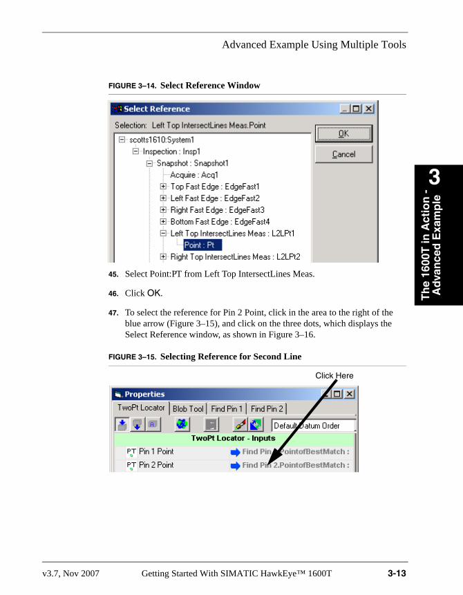
45. Select Point:PT from Left Top IntersectLines Meas.
46. Click OK.
47. To select the reference for Pin 2 Point, click in the area to the right of the blue arrow (Figure 3–15), and click on the three dots, which displays the Select Reference window, as shown in Figure 3–16.
FIGURE 3–15. Selecting Reference for Second Line
Click Here
v3.7, Nov 2007 Getting Started With SIMATIC HawkEye™ 1600T 3-13

Chapter 3 The 1600T in Action - Advanced Example
FIGURE 3–16. Select Reference Window
48. Select Point:Pt from Right Top IntersectLines Meas.
49. Click OK.
In the FrontRunner™ Edit window, TwoPt Locator and the Train button will display a red box until you train the tool. Also, the boxes around the untrained tool will remain dotted lines until trained.
50. To train the Two Pt Locator tool, highlight it and then click .
Your setup should appear as shown in Figure 3–17.
3-14 Getting Started With SIMATIC HawkEye™ 1600T v3.7, Nov 2007

Advanced Example Using Multiple Tools
Th
e 16
00T
in A
ctio
n -
A
dvan
ced
Exa
mp
le
3
FIGURE 3–17. TwoPt Locator Adjusted
51. Highlight Blob Tool (left pane).
52. Adjust the following Blob Tool properties:
– Use Autothreshold — Deselect it
– Low Threshold — Set to 128
– High Threshold — Set to 255
– Blob Polarity — Set to Light Parts
53. In the Editor window, adjust the ROI so that it encloses the switch, as shown in Figure 3–18.
v3.7, Nov 2007 Getting Started With SIMATIC HawkEye™ 1600T 3-15

Chapter 3 The 1600T in Action - Advanced Example
FIGURE 3–18. Blob Enclosing Opto Switch
54. To run the Job once and then stop, click .
When the Opto switch is on the right, the Job passes.
55. Highlight Acquire in the Step Tree (left pane).
Note: You may have to click the Acquire tab in the properties window.
56. Adjust the following Acquire properties:
– File List — Click C:\Vscape\Tutorials & Samples\Tutorials\HawkEye 1600T\Advanced Example Using Multiple Tools\chip01.tif, and then Add... to display the Open dialog box. Browse for the files opto02.tif, opto03.tif, opto04.tif, opto05.tif and opto06.tif from Windows. They are located at:
Blob
3-16 Getting Started With SIMATIC HawkEye™ 1600T v3.7, Nov 2007

Advanced Example Using Multiple Tools
Th
e 16
00T
in A
ctio
n -
A
dvan
ced
Exa
mp
le
3
C:\Vscape\Tutorials & Samples\Tutorials\HawkEye 1600T\Advanced Example Using Multiple Tools
Select opto02.tif, opto03.tif, opto04.tif, opto05.tif and opto06.tif. Click Open.
57. Click again.
When the Opto switch is on the left, as is the case with Opto02.tif, the Job fails, as shown in Figure 3–19.
FIGURE 3–19. Job Fails
58. Click again.
Because we used a TwoPt Locator in this Job, FrontRunner™ can find the switch even when the opto is rotated.
v3.7, Nov 2007 Getting Started With SIMATIC HawkEye™ 1600T 3-17

Chapter 3 The 1600T in Action - Advanced Example
In Figure 3–20, even though the opto is rotated to the left a couple of degrees, the Job finds the switch. The Job passes, because the switch is in the correct position for a pass.
FIGURE 3–20. Opto Rotated Left - Job Passes
59. Click again.
In Figure 3–21, the Job fails, because the switch is in the incorrect position for a pass.
3-18 Getting Started With SIMATIC HawkEye™ 1600T v3.7, Nov 2007

Advanced Example Using Multiple Tools
Th
e 16
00T
in A
ctio
n -
A
dvan
ced
Exa
mp
le
3
FIGURE 3–21. Opto Rotated Left - Job Fails
Figure 3–22 and Figure 3–23 show the same pass and fail results with the opto rotated to the right a couple of degrees.
v3.7, Nov 2007 Getting Started With SIMATIC HawkEye™ 1600T 3-19

Chapter 3 The 1600T in Action - Advanced Example
FIGURE 3–22. Opto Rotated Right - Job Passes
3-20 Getting Started With SIMATIC HawkEye™ 1600T v3.7, Nov 2007

Where To Now?
Th
e 16
00T
in A
ctio
n -
A
dvan
ced
Exa
mp
le
3
FIGURE 3–23. Opto Rotated Right - Job Fails
Where To Now?See the following manuals that make up the rest of the documentation set:
• Getting Started With SIMATIC Visionscape® Framegrabber Boards — Contains information about installing hardware and software; it also contains tutorials to help you familiarize yourself with SIMATIC Visionscape®.
• SIMATIC HawkEye™ 1600T Smart Camera Guide — Contains reference information about the SIMATIC HawkEye™ 1600T Smart Camera; specifically, system components, optics and lighting, connector pinouts, cable specifications, dimensions, and how to update the firmware on the Smart Camera.
• Perl Script Custom Tool Programmers Manual — Contains an explanation of what Perl is, how to use variables, arrays, conditional and loop statements,
v3.7, Nov 2007 Getting Started With SIMATIC HawkEye™ 1600T 3-21

Chapter 3 The 1600T in Action - Advanced Example
explains the Perl script, and provides examples of SIMATIC Visionscape® tools using Perl script language to define their operation and results.
• SIMATIC Visionscape® AppRunner User Manual — Contains information about using AppRunner.
• SIMATIC Visionscape® 0300 Framegrabber Board Guide — Framegrabber board for analog camera applications.
• SIMATIC Visionscape® 0740 Framegrabber Board Guide — Framegrabber board for high speed/high resolution camera applications.
• SIMATIC Visionscape® 0800 Framegrabber Board Guide — Framegrabber board for Camera Link camera applications.
• SIMATIC Visionscape® FrontRunner User Manual — Contains information about using FrontRunner.
• SIMATIC Visionscape® Programmers Kit (VSKit) Manual — Contains information about using VSKIT, which is a collection of libraries that aid in the development of user interface applications for SIMATIC Visionscape® products.
• SIMATIC Visionscape® Tools Reference — Contains information about all the tools in SIMATIC Visionscape® including builtin Perl script based tools.
• SIMATIC Visionscape® Readme — Contain latest details of this software revision that did not make it into the listed manuals.
• SIMATIC Visionscape® I/O Card — Refer to:
– Camera I/O 300 Card User Manual — For analog camera applications.
– Camera I/O 740 Card User Manual — For high speed high resolution camera applications.
3-22 Getting Started With SIMATIC HawkEye™ 1600T v3.7, Nov 2007

v3.7, Nov 2007 Getting Started With SIMATIC HawkEye™ 1600T Index-1
Index
BBlob
polarity 3-15tool example 2-3tree 2-3
DData Matrix Tool 2-34
example 2-34
EEdge Count 2-15, 2-16, 2-17Examples
advanced 3-2blob tool 2-3data matrix tool 2-34fast edge tool 2-18flaw tool 2-12
FFast Edge Tool Example 2-18File List 2-4, 2-7, 2-13, 2-19, 2-32, 2-35, 3-3, 3-16Flaw Tool Example 2-12
GGradient Threshold 2-21, 2-22, 2-23, 2-24
HHigh Threshold 2-5, 3-15Hole 2-3
IIcons 2-2
LLow Threshold 3-15
MMax
allowed 2-15, 2-16, 2-17edge count 2-14
number of blobs 2-5Min
allowed 2-15, 2-16, 2-17edge count 2-14
number of blobs 2-5
PPart 2-3Picture Mode 2-4, 2-13, 2-19, 2-32, 2-35, 3-3
SScan Direction 2-21, 2-22, 2-23, 2-24, 3-6, 3-7Sharpness 3-6, 3-7Step
train selected 2-39
TTool
method 2-14Train Selected Step 2-39Transition color 2-21, 2-22, 2-23, 2-24, 3-6, 3-7
UUse Autothreshold 2-5, 3-15