Get Up-to-Speed Quickly with Autodesk Land DesktopGet Up-to-Speed Quickly with Autodesk® Land...
21
December 2-5, 2003 ◊ MGM Grand Hotel Las Vegas Get Up-to-Speed Quickly with Autodesk ® Land Desktop Felicia Provencal CV11-1 This class will cover the fundamentals of Autodesk® Land Desktop. You'll learn how to use the tools for project management, point management, terrain modeling, parcel definition and output, horizontal alignment design, and COGO labeling. If you want to get up to speed quickly on this dynamic software, this class is for you. About the Speaker: Felicia is an Independent Consultant based in Hawaii with more than 17 years of experience working with AutoCAD®, AutoCAD Map™, Autodesk® Land Desktop, Autodesk® Civil Design, Autodesk® Survey, Autodesk® Field Survey, and Autodesk® Raster Design software. She writes the monthly tutorial on civil software products for Point A Toplines . A popular Autodesk University® instructor, Felicia conducts workshops and seminars and provides consulting and training services throughout the United States and the Pacific Basin. [email protected]
Transcript of Get Up-to-Speed Quickly with Autodesk Land DesktopGet Up-to-Speed Quickly with Autodesk® Land...

December 2-5, 2003 ◊ MGM Grand Hotel Las Vegas
Get Up-to-Speed Quickly with
Autodesk® Land Desktop
Felicia Provencal
CV11-1 This class will cover the fundamentals of Autodesk® Land Desktop. You'll learn how to use the tools for project management, point management, terrain modeling, parcel definition and output, horizontal alignment design, and COGO labeling. If you want to get up to speed quickly on this dynamic software, this class is for you.
About the Speaker: Felicia is an Independent Consultant based in Hawaii with more than 17 years of experience working with AutoCAD®, AutoCAD Map™, Autodesk® Land Desktop, Autodesk® Civil Design, Autodesk® Survey, Autodesk® Field Survey, and Autodesk® Raster Design software. She writes the monthly tutorial on civil software products for Point A Toplines. A popular Autodesk University® instructor, Felicia conducts workshops and seminars and provides consulting and training services throughout the United States and the Pacific Basin.
Get Up-to-Speed Quickly with Autodesk® Land Desktop
2
Autodesk® Land Desktop is a software suite containing programs used to manage point information, draw basic coordinate geometry (such as lines, curves, and spirals), annotate geometry, create terrain models, size and annotate parcels, create basic alignments, and several useful drafting and design utilities. Land Desktop operates on top of AutoCAD MAP Release to give you a full range of design and drafting tools. This course is an overview to performing the most common tasks with these software products. This class focuses on working with projects, point objects and labels, COGO linework and labels, horizontal alignment design, and terrain models.
Project Setup
When working with the Land Desktop, it is important to realize that you are working in a true networked project environment. This means that many people have access to design information at all times. The system is set up such that only one person can change design information, but many people can view and work with it. This project data is stored either on a local hard drive, or on a network drive for ease of access. This is by default stored in a directory called Land Projects on the drive where you install the Land Desktop, although it can reside anywhere. Be careful when choosing a project directory, it is easy to confuse the project directory with a drawing directory.
In the project directory are directories for each project on the system. There are an unlimited number of projects on the system. Each of these will have a name. It is best to use a project job number or other unique identifier for each project. In each project directory, you can store the drawings, raw data, adjusted data, and any other support files needed. When it comes time to back up or archive the project, everything is in one location for convenience.
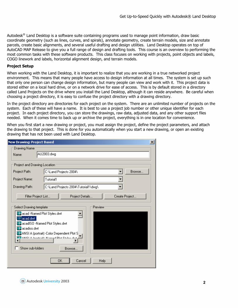
When you first start a new drawing or project, you must assign the project, define the project parameters, and attach the drawing to that project. This is done for you automatically when you start a new drawing, or open an existing drawing that has not been used with Land Desktop.

Get Up-to-Speed Quickly with Autodesk® Land Desktop
3
In this class, we will start a new drawing. It will ask for the drawing name and the project association. Use the Create Project button to create a new project called TRAINING. This project will be used to store the training drawings and data. You can choose the location of the files using the options in the dialog box.
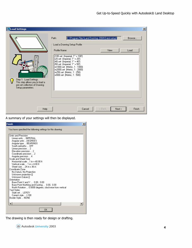
Once the project has been attached, the program will also ask for settings for the point database. The defaults are fine for now. Once this has been done, it will ask for drawing set up information including units, precision, scales, coordinate location, orientation, text styles, and border information. These settings can be saved to a file for ease in loading subsequent times.
Get Up-to-Speed Quickly with Autodesk® Land Desktop
4
A summary of your settings will then be displayed.
The drawing is then ready for design or drafting.

Get Up-to-Speed Quickly with Autodesk® Land Desktop
5
Point Objects and Labels
In the Land Desktop, there are two methods for displaying points: using point objects (typically for design purposes) and using point labels (typically for final drafting purposes). We will discuss both methods in this class. Points can be inserted manually (as for design purposes), imported from ASCII files (as we will see in this class), or brought in from a survey instrument with the Survey add-on. All point information is held in the point database.
The point database is an external, ODBC compliant database holding all of the point information. This database can be changed using any database program such as Microsoft Access or Corel Paradox. All point database and point object options are stored in the Point Settings. To change these, go to the Points pull-down menu and choose Point Settings.
The way points are displayed are controlled by the current point labeling style or marker style. A point marker is a somewhat temporary method of displaying point information. This can be thought of as a working mode. It shows the point information as you need to use it for design and interpretation. For drafting and final plot purposes, point labels can be used to display only the needed information (generally elevations). All of these settings are available from the Marker and Text tabs in this dialog.
These should be set before you insert your points. You should also make the appropriate layer current before inserting points. All points are placed on the current layer. The point style settings can also be changed for individual points by highlighting the points in the drawing, right-clicking, and picking the Display Properties command.
Two of the challenges faced when reducing survey field data is to separate different types of points to different layers (horizontal control shots vs. ground topo shots) and to add in the symbols (such as traverse stations and trees). Using description keys, sometimes known as field codes, you automate this process as points are brought into a drawing.
Description keys, or field codes, are generally short descriptions used by survey crews out in the field to identify what type of object was found. For example, the code “FL” may be used to identify a point shot on a fence line. Description keys can be any alphanumeric string, but must be unique within the project. For example, you should not use “FL” to mean either a point shot on a fence line or a flow line.

Get Up-to-Speed Quickly with Autodesk® Land Desktop
6
Before you can start bringing in point information, you have to set up a description key file and a point label style. We will discuss the point label style setup in a later section of this tutorial. The description key file stores information about what field codes are used, and what should be done with the points that match these codes. To create a new description key file or add codes to an existing description key file, from the main menu bar, go to the Points drop-down menu, then choose Point Management, then Description Key Manager.
When you use description keys for the first time, there is only one file called DEFAULT. Click the Create DescKey File toolbar button to create a new file. You can have as many different description key files as you need. Typically you will have different files for different survey field crews or surveying subcontractors when each crew or subcontractor uses a different set of standards. Choose the description key file you want to modify from the list on the left, then click the Create DescKey toolbar button to create a new description key.

Get Up-to-Speed Quickly with Autodesk® Land Desktop
7
The first thing that must be entered is the actual field code. This is referred to as the DescKey Code, short for description key code, in this dialog. In the example mentioned in the introduction, this was “FL” for fence line. Description key codes are case-sensitive.
You may use wildcards, such as the asterisk (*) or question mark (?), as part of the key code. For example, if your field crew enters “UP” to indicate a utility pole followed by the number found on the pole (such as UP #1436), you would use UP* for the description key code to find all utility poles regardless of the pole number.
The next thing you must enter is a description format. The description format can be used to override the description as it is entered in the field. If you field crew uses a description key code of “GS” for ground shots, you may want to override this with “GROUND SHOT” for the actual point description used in the project. Although there are many advanced techniques for parsing a description format, the most important one is $*, a dollar sign following by an asterisk. This will use the field code exactly as it is entered by the field crew for the point description. For more information on the other parsing options for description formats, please refer to the on-line Land Desktop User’s Guide provided with software.
The next step is to enter a layer name for the point objects. This way as points are brought into the current drawing, they are sent to the correct layers automatically. If the layer name entered in the description key manager does not exist in the current drawing, it will be created. Only the point objects are placed on these layers by the description keys.
The next two steps are optional. These are used to assign an AutoCAD block to different description keys. If a description key code is used to identify trees, a tree symbol can be placed in the drawing automatically. Not all description keys require symbols. For example, an open ground shot is typically just used to create contours, no symbols are placed at those locations.
The two steps are to choose a block name and the layer for these blocks. The symbol block name is a pop-up list showing all of the symbols found in the Symbol Block Drawing File path. This is set in the Point Settings dialog which will be shown later in this tutorial. If the symbol block name is sert to “none”, no block will be used for that description key. Like the point layers, the symbol layers will be created if they do not exist.
Any points found that do not match settings in the description key manager will be placed on the current layer, using its original description, and no symbols will be added.

Get Up-to-Speed Quickly with Autodesk® Land Desktop
8
Once a description key file has been created, it can be used by any drawing within the same project. If you want to use the same description key files in other projects, they can be saved to or loaded from a project prototype. Use the commands from the Manager drop-down menu in the Description Key Manager to do these tasks.
Once the description keys have been set up, you will need to set a point label style that ties the description keys to the point objects. To do this, from the main menu bar, go to the Labels drop-down menu and choose the Edit Label Styles command. From this dialog, choose the Point Label Styles tab.
In the Name edit field, type in a name for the new point label style. Then, in the lower right corner of this dialog, make sure all of the options for Description Keys are toggled on. Use the DescKey File pop-up list to choose the description key file. Once these settings are made, click the Save button to save the point label style, and OK to exit the dialog.
Once the style has been created, it must be set as the current point label style. To do this, from the main menu bar, go to the Labels drop-down menu and choose the Settings command. This will access the Labels Settings dialog. From here, choose the Point Labels tab.

Get Up-to-Speed Quickly with Autodesk® Land Desktop
9
Use the Current Label Style pop-up list to choose the correct point label style. Once this has been done, you can bring your point information into the current drawing. If you are using several different description key files in one project, it is recommended to set several different point label styles and switch between these as necessary.
When bringing in the point information using Description Keys, make sure the current point label style will be applied to the point objects. To do this, from the main menu bar, go to the Points drop-down menu and choose Point Settings. In the Point Settings dialog, choose the Insert tab.

Get Up-to-Speed Quickly with Autodesk® Land Desktop
10
Make sure the Use Current Point Label Style When Inserting Points option is toggled on. You can also set the folder where your symbol blocks are stored using the Browse button in the Search Path for Symbol Block Drawing Files section. This controls which blocks are shown in the pop-up list when creating the description key as discussed earlier. This can be any location on the system, including network drives. If you use the default symbol files provided by Land Desktop, you can modify or add your own blocks to these locations.
Points can be brought into the drawing using any method available to Land Desktop and they will be recognized if they match the description key file. They can be created on the fly using the commands from the Points drop-down menu. They can be imported from an external file using the Import/Export Points commands. They can be brought in from field book information or a data collector using tools from the Autodesk® Survey plug-in for Land Desktop. If points already exist in the current project, they can be added to the drawing using the Insert Points to Drawing command from the Points drop-down menu. All of these techniques recognize description key codes.
If you have downloaded and adjusted survey point information in another software program or if you are receiving information from another contractor or consulting firm, you can import it from an ASCII file into your project. An ASCII file is a plain text file describing each point on a separate line of the file. Typically the point number, northing, easting, elevation, and description are listed in this file.
From the Points pull-down menu, pick the Import/Export Points sub-menu, then the Format Manager. This shows you how the point information should be organized, or allows you to create your own custom format.
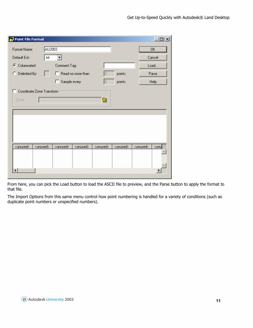
You can also preview point files to make sure they are compatible with the format selected. Highlight the format name and pick the View button from the Format Manager to load the Point File Format screen.
Get Up-to-Speed Quickly with Autodesk® Land Desktop
11
From here, you can pick the Load button to load the ASCII file to preview, and the Parse button to apply the format to that file.
The Import Options from this same menu control how point numbering is handled for a variety of conditions (such as duplicate point numbers or unspecified numbers).

Get Up-to-Speed Quickly with Autodesk® Land Desktop
12
Once the format and options have been set, you can import the points using the Import Points command from this same menu. Here you will specify the format to use and the name of the file to import. All points imported can be added to a group as well.
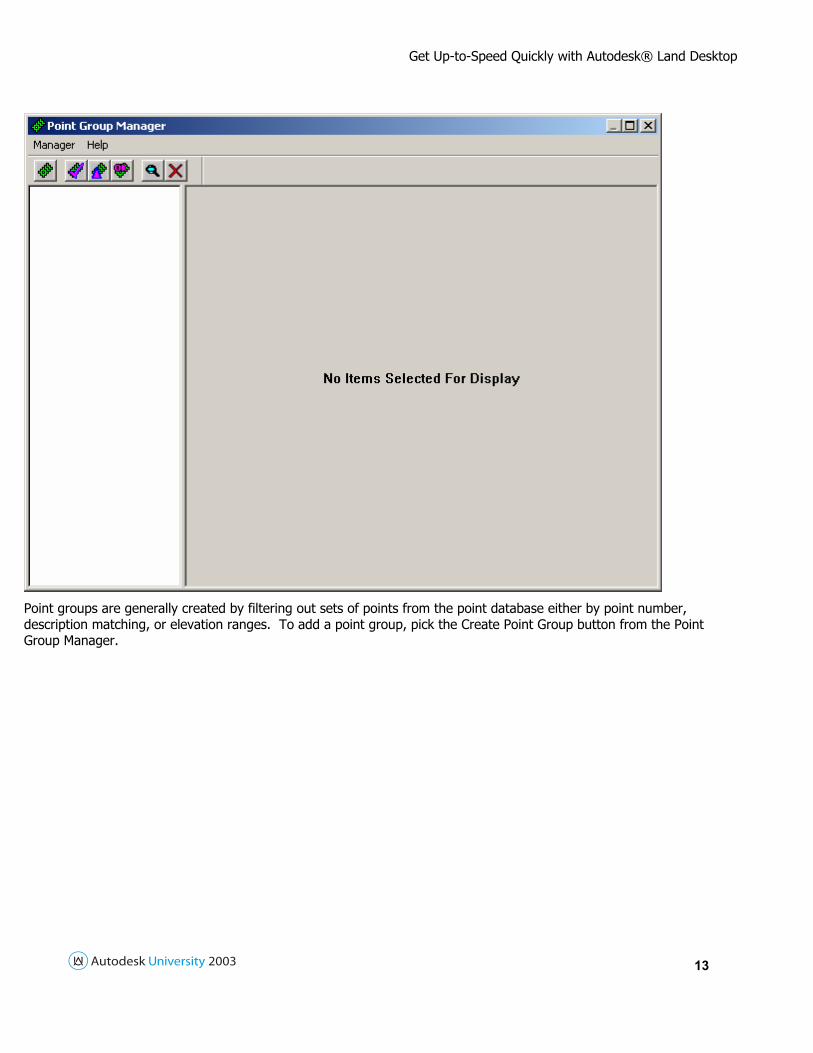
Points can be collected into groups for ease in management and re-use of the point information further down the design stream. To set up and manage point groups, go to the Points pull-down menu, pick the Point Management sub-menu, then the Point Group Manager command.
Get Up-to-Speed Quickly with Autodesk® Land Desktop
13
Point groups are generally created by filtering out sets of points from the point database either by point number, description matching, or elevation ranges. To add a point group, pick the Create Point Group button from the Point Group Manager.

Get Up-to-Speed Quickly with Autodesk® Land Desktop
14
You will need to enter a name for the group. Point groups can be created by filtering in points from the database using the Include tab, filtering out unwanted points using the Exclude tab, or by using Description Key settings as we set up previously.
You can use the Summary tab to view information about the group including the total number of points in the group. Once a point group has been built, it can be linked to the point database and update itself automatically as point information is added, removed, or edited.
COGO Linework and Labels
The Land Desktop has a wide variety of ways to create linework. All of these are found in the Lines/Curves pull-down menu. When any of these commands are selected, there are three toggles that can be used at any prompt asking for point selection. These are .P, .G, and .N. The .P toggle prompts for point numbers, rather than selected points. The .G toggle allows you to select any part of a point marker. This makes it easier to select exact points in congested areas of a drawing, or to select by description rather than number. The .N toggle allows you to specify points by entering Northings and Eastings. Type the toggle in response to any point selection prompt. Type in the toggle a second time to turn it off.
If you are entering metes and bounds (or legal descriptions), use the By Direction command from the Lines/Curves pull-down menu. This will allow you to type in true azimuths or bearings and distances. All Land Desktop commands use the DDD.MMSS format for azimuth entry. You do not need to type in d or ' or " for azimuth entries. Another commonly

Get Up-to-Speed Quickly with Autodesk® Land Desktop
15
used command is the By Point # Range. This is the most efficient method for entering ranges of point numbers using the hyphen.
The curve drawing commands can be used when specific criteria (such as curve length or delta) need to be specified. There is also the Special Lines command for drawing brush line, fences, or rock walls. You can also draw spirals for roadway and interchange design. Speed tables that conform to AASHTO standards are provided.
Once the linework has been drawn, it can be labeled in a variety of ways. As with point and contours, you can set up COGO label styles for lines, curves, and spirals. Go to the Labels pull-down menu and pick the Settings command to select a label style and determine how labels are to be applied.
Use the Edit Label Styles command from the same menu to modify or verify the labeling options. Use the Edit Tag Styles if line and curve tags and tables are to be used. This is most useful in congested drawings.
You can edit the existing label styles, or create your own. The path for the label style files is shown in the Settings dialog box described earlier.

Get Up-to-Speed Quickly with Autodesk® Land Desktop
16
Once the styles have been set, you can label linework. You can either use the Add Dynamic Labels or Add Static Labels commands from the Labels pull-down menu, or you can select all the linework to be labeled, right-click, and pick the Add Dynamic Label or Add Static Label command from the pop-up menu. Use dynamic labels if you want your labels to update automatically and static labels if you want to avoid adjusting labels my mistake. If you will be creating line or curve tables, you can use the Add Tag Label command. If you are going to be labeling a large amount of linework at one time, you may want to bring up the Style Properties dialog bar. Go to the Labels drop-down menu and choose Show Dialog Bar. This allows you to change the label type and style on the fly.
If linework needs to be modified after creation, you can use any AutoCAD command or any command from the Lines/Curves pull-down menu. If you have the option to update labels when entities change turned on, the corresponding labels will update automatically even if they are on a frozen layer. Be careful of this option. If you normally create property corner marks and trim the property lines back to them, the labels will update.
Get Up-to-Speed Quickly with Autodesk® Land Desktop
17
As noted previously, labels can be set to update when the linework changes. Alternatively, you can use the Update Labels command to update the labels when the style or entity changes. There is also an option to flip the label. This is useful if a line needs to be reversed 180 degrees. You can remove a label using the Delete Labels command. If you use the AutoCAD ERASE command, the label will re-appear when the style or entity is modified. With the Land Desktop, labels are intelligent and a tag is placed on each line or curve labeled. The tag is invisible and cannot be removed with the AutoCAD ERASE command. If you want to remove only the tag linking the label to the linework, use the Dis-Associate Labels command. This will leave the text, but remove the tag. Labels can then be erased and edited using AutoCAD commands.
Terrain Models
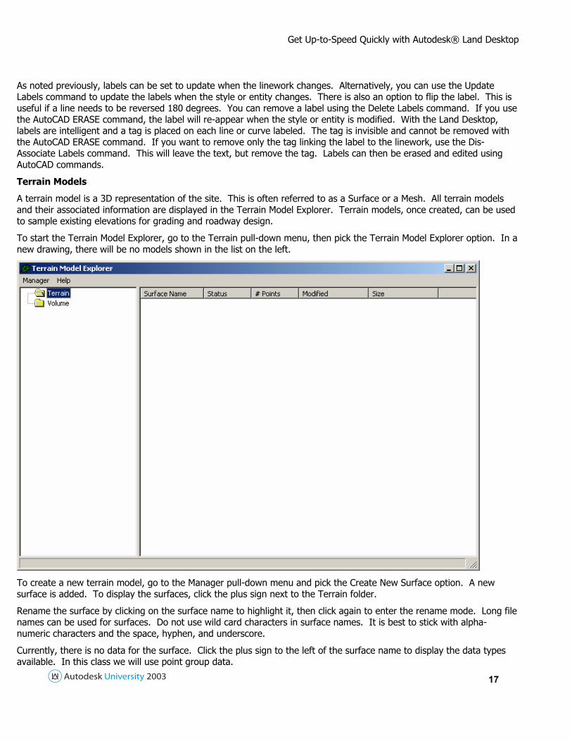
A terrain model is a 3D representation of the site. This is often referred to as a Surface or a Mesh. All terrain models and their associated information are displayed in the Terrain Model Explorer. Terrain models, once created, can be used to sample existing elevations for grading and roadway design.
To start the Terrain Model Explorer, go to the Terrain pull-down menu, then pick the Terrain Model Explorer option. In a new drawing, there will be no models shown in the list on the left.
To create a new terrain model, go to the Manager pull-down menu and pick the Create New Surface option. A new surface is added. To display the surfaces, click the plus sign next to the Terrain folder.
Rename the surface by clicking on the surface name to highlight it, then click again to enter the rename mode. Long file names can be used for surfaces. Do not use wild card characters in surface names. It is best to stick with alpha-numeric characters and the space, hyphen, and underscore.
Currently, there is no data for the surface. Click the plus sign to the left of the surface name to display the data types available. In this class we will use point group data.

Get Up-to-Speed Quickly with Autodesk® Land Desktop
18
It is recommended to use point groups when defining surfaces rather than point files to avoid control points, invert shots, etc. Point files may be used if you are sure that all of the point information in the file is valid. Points may have negative or zero elevations. You may filter out negative values when it is time to build the surface.
To specify a point group to use, right-click on the point group option and pick the Add Point Group option. To use a point file, right-click on the Point Files option and pick the Add Point File command. You can also use this option to create surfaces from AutoCAD objects such as blocks, 3D Lines, 3D faces, and Polyface meshes. This is very useful when importing data from another program such as Terramodel.
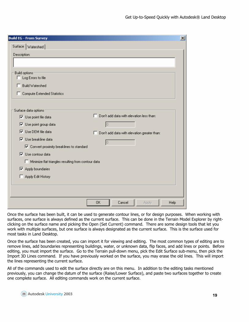
Once all of the data has been specified, you can create the surface by right-clicking on the surface name, then picking the Build option. This command will prompt for the type of information to use in creating the surface, and how that information should be used.
Get Up-to-Speed Quickly with Autodesk® Land Desktop
19
Once the surface has been built, it can be used to generate contour lines, or for design purposes. When working with surfaces, one surface is always defined as the current surface. This can be done in the Terrain Model Explorer by right-clicking on the surface name and picking the Open (Set Current) command. There are some design tools that let you work with multiple surfaces, but one surface is always designated as the current surface. This is the surface used for most tasks in Land Desktop.
Once the surface has been created, you can import it for viewing and editing. The most common types of editing are to remove lines, add boundaries representing buildings, water, or unknown data, flip faces, and add lines or points. Before editing, you must import the surface. Go to the Terrain pull-down menu, pick the Edit Surface sub-menu, then pick the Import 3D Lines command. If you have previously worked on the surface, you may erase the old lines. This will import the lines representing the current surface.
All of the commands used to edit the surface directly are on this menu. In addition to the editing tasks mentioned previously, you can change the datum of the surface (Raise/Lower Surface), and paste two surfaces together to create one complete surface. All editing commands work on the current surface.

Get Up-to-Speed Quickly with Autodesk® Land Desktop
20
Horizontal Alignments
Horizontal alignments are used to control the plan view of any type of baseline. These typically represent centerline of road. Horizontal alignments can be made of lines, arcs, poylines, or polyline representations of spiral segments. The linework can be drawn using any AutoCAD command or the commands from the Lines/Curves pull-down menu.
Once the linework has been created, it must be defined as an alignment. Depending on what types of entities are being used, use the appropriate command from the Alignments pull-down menu. The definition process will add alignment information to an external database where it can be accessed from any drawing in the project.
Note that the starting station does not have to be the beginning of the alignment, nor does stationing have to start at zero. Once the alignment has been defined, it can be edited using a spreadsheet type interface. Go to the Alignments pull-down menu and choose Edit.
You can also use this command to create alignment reports. Alignments can also be stationed in the current drawing. Before creating the station labels, go to the Alignments pull-down menu and choose Station Label Setttings.

Get Up-to-Speed Quickly with Autodesk® Land Desktop
21
Once these settings have been made, go to the Alignments pull-down menu and choose Create Station Labels to place the labels along the alignment. Alignments can also be staked out, offset, and used as the baseline to locate points or linework for any information within the project.